Embed Size (px)
Citation preview

INDIANA DEPARTMENT OF TRANSPORTATION—2013 DESIGN MANUAL
CHAPTER 55
Geometric Design of Existing Non-Freeway (3R)
Design
Memorandum Revision
Date Sections Affected
13-09 April 2013 Ch. 55 13-11 May 2013 55-5.04(02) 14-10 July 2014 55-3.0, 55-4.01(03), Figures 55-3A through 55-3H
NOTE: This chapter is currently being re-written and its content will be included in Chapter 302 in the future.

Page 2 2013 Indiana Design Manual, Ch. 55
TABLE OF CONTENTS
TABLE OF CONTENTS ................................................................................................................ 2
LIST OF FIGURES ........................................................................................................................ 4
55-1.0 INTRODUCTION .............................................................................................................. 5
55-2.0 GENERAL REQUIREMENTS .......................................................................................... 6 55-2.01 Applicability ................................................................................................................. 6
55-2.01(01) 3R Scope-of-Work Definition ............................................................................ 6 55-2.01(02) National Highway System (NHS) Project .......................................................... 8 55-2.01(03) Non-NHS Project ............................................................................................... 9 55-2.01(04) Procedures ........................................................................................................ 11
55-2.02 Background ................................................................................................................. 11 55-2.03 Geometric-Design Approach ...................................................................................... 12 55-2.04 3R Project Evaluation ................................................................................................. 13
55-3.0 GEOMETRIC DESIGN CRITERIA [REV. JUL 2014] .................................................. 17
55-4.0 GEOMETRIC DESIGN ................................................................................................... 20 55-4.01 Design Controls .......................................................................................................... 20
55-4.01(01) Traffic-Volume Analysis ................................................................................. 20 55-4.01(02) Design Speed ................................................................................................... 20 55-4.01(03) Adherence to Design Criteria [Rev. Jul. 2014] ................................................ 21
55-4.02 Sight Distance ............................................................................................................. 21 55-4.03 Horizontal Alignment ................................................................................................. 22
55-4.03(01) Minimum Horizontal-Curve Radius ................................................................ 22 55-4.03(02) Superelevation .................................................................................................. 23 55-4.03(03) Reverse Curves ................................................................................................ 23 55-4.03(04) Broken-Back Curves ........................................................................................ 24 55-4.03(05) Curves in Series ............................................................................................... 24 55-4.03(06) Shoulder Treatment .......................................................................................... 24 55-4.03(07) Horizontal Sight Distance ................................................................................ 25 55-4.03(08) Traffic-Control Devices ................................................................................... 25
55-4.04 Vertical Alignment ..................................................................................................... 25 55-4.04(01) Grades .............................................................................................................. 25 55-4.04(02) Climbing Lane ................................................................................................. 26 55-4.04(03) Crest Vertical Curve ........................................................................................ 26 55-4.04(04) Sag Vertical Curve ........................................................................................... 27 55-4.04(05) Curves in Series ............................................................................................... 27 55-4.04(06) Angle Point ...................................................................................................... 28

2013 Indiana Design Manual, Ch. 55 Page 3
55-4.05 Cross-Section Elements .............................................................................................. 28 55-4.05(01) Travel-Lane Width ........................................................................................... 28 55-4.05(02) Shoulder Width ................................................................................................ 29 55-4.05(03) Paved-Roadway Width .................................................................................... 29 55-4.05(04) Lane and Shoulder Cross Slopes ...................................................................... 29 55-4.05(05) Parking Lanes ................................................................................................... 29 55-4.05(06) Curbs ................................................................................................................ 30 55-4.05(07) Sidewalks ......................................................................................................... 30 55-4.05(08) Median Width .................................................................................................. 31 55-4.05(09) Fill or Cut Slopes ............................................................................................. 31 55-4.05(10) Right of Way .................................................................................................... 32
55-4.06 Intersection At-Grade ................................................................................................. 33 55-4.06(01) General Design Controls .................................................................................. 33 55-4.06(02) Turning Radius ................................................................................................. 33 55-4.06(03) Turn Lane ......................................................................................................... 34 55-4.06(04) Intersection Sight Distance .............................................................................. 35
55-5.0 ROADSIDE SAFETY ...................................................................................................... 35 55-5.01 Analysis of Accident Data .......................................................................................... 35 55-5.02 Obstruction-Free Zone ............................................................................................... 36 55-5.03 Treatment of Obstruction ........................................................................................... 38
55-5.03(01) Application ....................................................................................................... 38 55-5.03(02) Drainage Structure ........................................................................................... 41
55-5.04 Roadside Barrier ......................................................................................................... 42 55-5.04(01) Existing Guardrail ............................................................................................ 42 55-5.04(02) New Guardrail Installation [Rev. May 2013] .................................................. 43
55-6.0 BRIDGE ........................................................................................................................... 44 55-6.01 General Requirements ................................................................................................ 44 55-6.02 Bridge To Remain In Place ........................................................................................ 45 55-6.03 Bridge Requiring Replacement or Major Reconstruction .......................................... 46
55-7.0 MISCELLANEOUS DESIGN ELEMENTS ................................................................... 47 55-7.01 Traffic-Control Devices.............................................................................................. 47 55-7.02 Railroad Crossing Warning Devices and Surface ...................................................... 47 55-7.03 Trimming of Trees and Brush .................................................................................... 47 55-7.04 Encroachment ............................................................................................................. 48
55-8.0 ACCIDENT DATA ANALYSIS ..................................................................................... 48 55-8.01 Accident-Analysis Procedures ................................................................................... 48
55-8.01(01) Responsibilities ................................................................................................ 48 55-8.01(02) Accident Summaries ........................................................................................ 48
55-8.02 Probable Causes and Safety Enhancements ............................................................... 50

Page 4 2013 Indiana Design Manual, Ch. 55
FIGURES ...................................................................................................................................... 51 LIST OF FIGURES Figure Title 55-2A 3R/4R Systems 55-3A Geometric Design Criteria for Rural Arterial, 3R Project [Rev. Jul 2014] 55-3B Geometric Design Criteria for Rural Collector, State Route,3R Project [Rev. Jul 2014] 55-3C Geometric Design Criteria for Rural Collector, Local-Agency Route,3R Project [Rev.
Jul 2014] 55-3D Geometric Design Criteria for Rural Local Road, 3R Project [Rev. Jul 2014] 55-3E Geometric Design Criteria for Urban Arterial, Four or More Lanes, 3R Project [Rev.
Jul 2014] 55-3F Geometric Design Criteria for Urban Arterial, Two Lanes, 3R Project [Rev. Jul 2014] 55-3G Geometric Design Criteria for Urban Collector, 3R Project [Rev. Jul 2014] 55-3H Geometric Design Criteria for Urban Local Street, 3R Project [Rev. Jul 2014] 55-4A K-Value For Sag Vertical Curve (Comfort Criteria, 3R Project) 55-5A Appurtenance-Free Zone 55-5A(1) Clear Zone / Guardrail at Culvert 55-5B Runout Length, LR (ft) for Restrictive Condition 55-8A Editable Accident Analysis Form
55-8B Accident Analysis Form Codes 55-8C Collision Diagram Codes 55-8D Contributing Circumstances 55-8E Accident Analysis

2013 Indiana Design Manual, Ch. 55 Page 5
CHAPTER 55
GEOMETRIC DESIGN OF EXISTING NON-FREEWAY (3R)
55-1.0 INTRODUCTION
Section 40-6.0 identifies project scopes of work as follows:
1. new construction;
2. complete reconstruction, freeway;
3. partial reconstruction, freeway (4R);
4. reconstruction, non-freeway (4R);
5. 3R project, non-freeway;
6. 3R project ,freeway;
7. partial 3R project, non-freeway;
8. high-accident location improvement, non-freeway; and
9. traffic-control-devices project.
Chapter 53 provides tables of geometric design criteria which apply to a new construction or
reconstruction project. Chapters 40 through 52 provide design concepts and criteria which are
directly applicable to new construction or reconstruction. For this type of project, the designer
has the liberty of designing the highway to satisfy the most desirable and stringent criteria
practical.
The geometric design of a project on an existing highway is viewed from a different perspective.
This type of project is often initiated for reasons other than geometric design deficiencies (e.g.,
pavement deterioration, bridge replacement), and it often must be designed within restrictive
right of way, and financial or environmental constraints. Therefore, the design criteria for new
construction are often not attainable without major and, frequently, unacceptable adverse
impacts. At the same time, however, the Department must use the opportunity to make cost-
effective, practical improvements to the geometric design of an existing highway or street.
For these reasons, INDOT has adopted different limits for geometric design criteria for a project
on an existing highway which are often lower than the values for new construction. The criteria
for an existing highway are based on a sound, engineering assessment of the underlying

Page 6 2013 Indiana Design Manual, Ch. 55
principles behind geometric design and on how the criteria for new construction can be modified
to apply to an existing highway.
This chapter provides the Department’s criteria for a 3R non-freeway project. These criteria
balance the many competing and often conflicting objectives. The objectives include improving
an existing highway, minimizing the adverse impacts of highway construction on an existing
highway, and improving the greatest longitudinal distance within the available funds for capital
improvements. Where the 3R project scope of work is selected, costly work (e.g., bridge
reconstruction or replacement, alignment improvements), which has a long service life and can
be incorporated into a future 4R project, should desirably be constructed to satisfy 4R design
criteria as part of the 3R project.
55-2.0 GENERAL REQUIREMENTS
55-2.01 Applicability
55-2.01(01) 3R Scope-of-Work Definition
A 3R project (rehabilitation, restoration, and resurfacing) on an existing non-freeway is intended
to extend the service life of the existing facility and to enhance highway safety. A 3R project
should make cost-effective improvements to the existing geometrics, where practical. This type
of work on the mainline or at an intersection is on the existing alignment. Minimal right-of-way
acquisition is required. Improvements for a 3R non-freeway project can include a combination
of the following:
1. pavement resurfacing or rehabilitation or a limited amount of pavement reconstruction
(30% or less of the traveled-way area);
2. bridge rehabilitation or replacement;
3. lane or shoulder widening;
4. upgrading the structural strength of shoulders;
5. flattening an occasional horizontal or vertical curve;
6. adjustments to the roadside clear zone;
7. flattening side slopes;

2013 Indiana Design Manual, Ch. 55 Page 7
8. converting an existing median to a 2-way left-turn lane (TWLTL);
9. adding a climbing lane;
10. converting an uncurbed urban street into a curbed street;
11. revising the location, spacing, or design of existing drives along the mainline;
12. adding or removing a parking lane;
13. bridge widening and associated substructure work to accommodate the widening;
14. bridge-railing upgrading or replacement;
15. bridge-deck overlay;
16. work to preserve the bridge substructure;
17. adding a sidewalk;
18. relocating utility poles;
19. upgrading guardrail or other safety appurtenances to satisfy certain criteria;
20. other geometric or safety improvements to an existing bridge within the project limits;
21. drainage improvements;
22. increasing vertical clearance at an underpass;
23. intersection improvement (e.g., adding turn lanes, flattening turning radii, channelization,
sight-distance improvements, etc.);
24. adding a new or upgrading an existing traffic signal; or
25. other spot improvements.
Specifically related to the level of pavement improvement, the following definitions apply.

Page 8 2013 Indiana Design Manual, Ch. 55
1. Resurfacing. Resurfacing consists of the placement of additional surface material over
the existing restored or rehabilitated roadway or structure to improve serviceability or to
provide additional strength.
2. Restoration or Rehabilitation. Restoration or rehabilitation is defined as work required to
return the existing pavement to a condition of adequate structural support or to a
condition adequate for the placement of an additional stage of construction. This may
include milling the existing pavement.
55-2.01(02) National Highway System (NHS) Project
For long-range transportation planning purposes, INDOT has evaluated the State highway system
to determine which routes warrant reconstruction, or 4R work, and which routes warrant a 3R-
type improvement. Figure 55-2A shows a map of the State highway system which indicates 3R
and 4R routes. The following will apply to the use of Figure 55-2A for such routes on the NHS.
1. General. The factors which will determine if a project should be classified as 3R or 4R
are as follows:
a. If 70% or more of the existing pavement area of the traveled way can be retained
and resurfaced, the project may be classified as 3R. If not, the project is classified
as a 4R project.
b. An assessment of the level of service (LOS) for the 10-year traffic volume
projection, which is based upon the expected service life of the pavement, can be
used to determine if the project is 3R or 4R.
Other factors should also be considered when making the project scope of work
determination (e.g., accident rates).
2. 4R Non-Freeway Route. The Production Management Division’s Office of
Environmental Services, or the local jurisdictional agency will determine the LOS for the
10-year traffic volume projection based on the discussion in Section 40-2.0. If this is
LOS of D or better, it will be acceptable to design the project using the 3R geometric
design criteria described in this chapter. If the projected LOS will not satisfy LOS of D,
the facility will be designed according to the criteria for new construction or
reconstruction. Each bridge replacement, bridge deck replacement, or bridge-widening
should be designed to satisfy new construction, or 4R, criteria.

2013 Indiana Design Manual, Ch. 55 Page 9
3. 3R Non-Freeway Route. The project will be designed according to the 3R geometric
design criteria described in this chapter. However, consideration could be given to using the 4R criteria.
4. Combination Project. Where a project will include both 3R and 4R work, the overall
project scope-of-work classification should be based on the predominant type of work. For example, a 6-mi resurfacing project which includes the replacement of one of the mainline bridges to 4R criteria will be classified as a 3R project, unless the bridge is considered to be a major structure and its replacement cost is equal to or greater than that of the 3R roadway work. 55-2.01(03) Non-NHS Project The project scope-of-work definitions in Section 40-6.01 and Figure 55-2A, 3R/4R Systems, are intended only as general guidance for a non-NHS project. The decision on classifying a project that is not on the NHS should be made based on the future plans of the jurisdictional highway agency for the entire road between logical termini for the foreseeable future (20 years). All future plans for a road must consider current and projected traffic volumes, anticipated land use, and accident experience. The following provides examples of applying this concept to a non-NHS project. 1. Example 1. Approximately 60% of the pavement on a 6-mi section of a county road will
be replaced. The remainder of the pavement is in reasonably good condition and only requires milling and resurfacing. The 6-mi section is part of a 30-mi county road which is the main highway between two small towns. The existing road has a LOS of A, and it is anticipated to provide a LOS of B based on 20-year projected traffic volume. There is no adverse accident experience for the past three years. Based on this information, a highway agency could decide to designate the 3R classification and construct the road to 3R design criteria. This is acceptable even though more than 30% of the pavement is being completely replaced.
2. Example 2. Approximately 40% of the pavement on a 6-mi section of county road will
be replaced. The remainder of the segment will be resurfaced. This segment of road is part of a 25-mi county road which connects two small towns. This county road is located approximately 20 mi from a major metropolitan area. It is anticipated that, within the next 20 years, there will be considerable residential and commercial development adjacent to this stretch of county road because of its proximity to the rapidly expanding metropolitan area. The current LOS is B, but projected traffic volume indicates that the

Page 10 2013 Indiana Design Manual, Ch. 55
LOS will drop to D in 10 years and to F in 20 years. For this situation, the highway agency has two options. It can design the project to 3R criteria for the present and, then, undertake a 4R project in 10 years when the pavement will likely be in need of major work. Its second option is to construct the project to 4R criteria now to satisfy future traffic demands.
3. Example 3. A 6-mi section of highway, which is located on INDOT’s 3R highway
system, requires complete pavement replacement because of poor drainage. The Central Office has rechecked the status of this highway with the district office and verified that there are no plans for work on the remainder of this route in the future (20 years) except for 3R-type work. The current LOS is B, and it is anticipated to remain at B for the next 20 years. There is no adverse accident experience and no anticipated major land development along the route. INDOT can decide to only construct the project to 3R design criteria, though all of the pavement is being replaced.
4. Example 4. A 200-ft-long bridge on the State’s 3R system requires complete
replacement. There are sharp horizontal curves on each end of the bridge where numerous accidents have occurred during the last three years. It has been decided to correct the poor alignment on the bridge approaches and to construct the approaches and bridge on a new location. The total length of the project is 1.5 mi. The Central Office has discussed the status of this road with the district office and both agreed that it should remain on the 3R system. The current LOS is B, and it is estimated that the LOS will be C in 20 years. There are no plans except to perform 3R-type work to the remainder of the road for the future (20 years). For this situation, INDOT can decide to construct the entire project to 3R design criteria.
5. Example 5. A 6-mi segment of a route on INDOT’s 3R system requires replacing 20% of
the pavement and resurfacing the remaining 80%. The current LOS is D and will deteriorate to E in 5 years. There is rapid residential, commercial, and industrial development in the area. Both the Central and district offices agree that the entire route was properly classified as a 3R route. However, this one 6-mi segment is an exception because rapid growth adjacent to this segment is expected to occur. The appropriate solution in this situation is to upgrade the facility to accommodate anticipated traffic demand for the next 20 years and to design the project to 4R design criteria.

2013 Indiana Design Manual, Ch. 55 Page 11
55-2.01(04) Procedures
For an INDOT project, the project scope of work is selected based on the following procedure.
1. The district office initially identifies the project scope.
2. The project is programmed based on the project scope determined by the district.
3. The Production Management Division’s Office of Environmental Services will make the
final decision on the scope of work. However, for an Interstate-system project which has
an estimated construction cost exceeding $1 million, FHWA will meet with
representatives of the Office of Environmental Services to cooperatively agree on the
project classification. This will occur as early in the project-scoping process as possible
so that FHWA may have input on each project which is classified as 4R. The meeting
will be held as soon as an initial concept for the project design has been developed.
4. The Production Management Division, during project design, may re-evaluate the project
scope and request the Office of Environmental Services to modify the scope of work.
For a Federal-aid project not on the State highway system, the project scope of work
determination will be based on the future plans of the local agency for improvements to its local
road or street system. The philosophy described in Section 55-2.01(02) Item 2 for a 4R non-
freeway State route should also be applied to a local project. The local agency must submit a
letter to the Planning Division to document the local agency's plans on that facility in the
foreseeable future. If the project is on the Interstate system and the estimated construction costs
exceed $1 million, the Planning Division will schedule a meeting with the local agency and the
FHWA to determine the project’s classification (3R or 4R). This meeting should occur early in
the scoping process so that the FHWA may have input on each project that is classified as 4R.
55-2.02 Background
The 1976 Federal-aid Highway Act made it possible for the Department and local agencies to use
Federal funds to extend the service life for the maximum number of centerline miles possible for
the total highway system. On June 10, 1982, the FHWA issued its Final Rule entitled Design
Standards for Highways; Resurfacing, Restoration and Rehabilitation of Streets and Highways
Other Than Freeways. This rule modified 23CFR Part 625.4 to adopt a flexible approach to the
geometric design of a 3R non-freeway project. Part 625.4 was modified again on March 31,
1983, to explicitly state that one objective of a 3R project is to enhance highway safety. In the
rule, FHWA determined that it was not practical to adopt 3R design criteria for nationwide

Page 12 2013 Indiana Design Manual, Ch. 55
application. Instead, each State was permitted to develop its own criteria or procedures for the
design of a 3R project. This approach is in contrast to the application of criteria for new
construction and reconstruction, for which the AASHTO A Policy on Geometric Design of
Highways and Streets provides nationwide criteria for application. The flexible approach for 3R
work permits Indiana to tailor its design criteria for its 3R program consistent with the conditions
which prevail within the State. A highway for which geometrics were established some time ago
is still capable of providing useful transportation service. Minor improvements will most often
make such a highway serviceable for many more years.
In 1987, the Transportation Research Board (TRB) published Special Report 214, SR214
Designing Safer Roads; Practices for Resurfacing, Restoration and Rehabilitation. The
objective of the TRB study was to examine the safety cost-effectiveness of highway geometric
design criteria and to recommend minimum design criteria for a 3R project on a non-freeway.
See SR214 for more discussion.
INDOT has developed its own criteria for the geometric design of a 3R non-freeway project. Its
objectives in developing these criteria may be summarized as follows:
1. extend the service life of the existing facility and to return its features to a condition of
structural or functional adequacy;
2. incorporate highway safety enhancements, where judged to be cost effective; and
3. incorporate cost-effective, practical improvements to the geometric design of the existing
facility.
55-2.03 Geometric-Design Approach
The Department’s approach to the geometric design of a 3R non-freeway project is to adopt,
where justifiable, a revised set of numerical criteria. The design criteria throughout the other
Manual chapters provide the frame of reference for the 3R criteria. The following summarizes
the approach which has been used.
1. Design Speed. As discussed in Section 55-4.01, the design speed will be based on the
existing posted or legal speed limit. The selected 3R design speed will then be used to
evaluate all geometric design features of the existing highway which are based on speed
(e.g., horizontal and vertical curvature).

2013 Indiana Design Manual, Ch. 55 Page 13
2. Cross-Section Width. The criteria shown in Chapter 53 for new construction or
reconstruction have been evaluated relative to the constraints of a 3R project. Where
justifiable, the cross-section width criteria have been reduced. Where a range of values is
provided in the Chapter 53 figures, the upper values have been incorporated into the 3R
criteria to provide a desirable objective. This provides an expanded range of acceptable
values for application on a 3R project. See Section 55-4.05 for additional discussion on
cross-section width.
3. Other Design Criteria. Part V includes other proper geometric design techniques. These
criteria are obviously applicable to new construction or reconstruction. For a 3R project,
these criteria have been evaluated and a judgment has been made on their proper
application to a 3R project. Unless stated otherwise in this chapter, the criteria in other
chapters applicable to a 3R project should be incorporated if practical.
4. Evaluation. Available data, e.g., accident experience, should be evaluated when
determining the geometric design of a 3R project. The following section discusses 3R
project evaluation in more detail.
55-2.04 3R Project Evaluation
Sections 55-3.0 to 55-7.0 provide the specific geometric-design and roadside-safety criteria
which will be used to determine the design of a 3R project. In addition, other factors must be
considered in a 3R project design. Applicable evaluations should be conducted as may be
deemed necessary. These evaluations are discussed below.
1. Accident Experience. The historical accident data within the project limits will be
evaluated. This is the most critical element of 3R project evaluation to determine the
appropriate level of geometric and safety improvement. Accident data is available from
the Planning Division’s Office of Safety and Mobility. Section 55-8.0 further describes
the Department's accident-analysis procedures.
2. Existing Geometrics. The designer will review the as-built plans and combine this review
with the field review and field survey to determine the existing geometrics within the
project limits. This includes lane and shoulder widths, horizontal and vertical alignment,
intersection geometrics, and roadside-safety design.
3. Speed Studies. The designer will make the initial determination if a speed study is
required for project design. The speed study should be conducted before the field review.

Page 14 2013 Indiana Design Manual, Ch. 55
The speed study will be conducted by the district for an INDOT project, or by the local
public agency or its consultant for a local-agency project.
4. Physical Constraints. The physical constraints within the limits of the 3R project will
often determine what geometric improvements are practical and cost-effective. These
include topography, adjacent development, available right-of-way, utilities, and
environmental constraints (e.g., wetlands).
5. Field Review. The designer will conduct a thorough field review of the proposed 3R
project. Other personnel should attend the field review as appropriate, including
personnel from traffic, maintenance, construction, local agencies, etc. The objective of
the field review should be to identify potential safety hazards and potential safety
improvements to the facility.
6. Pavement Condition. A 3R project is sometimes programmed because of a significant
deterioration of the existing pavement structure, including subbase, base, and surface
courses. The extent of deterioration will determine the necessary level of pavement
improvements. This decision will also influence the extent of practical geometric
improvements. For a road to be eligible for resurfacing, the pavement should exhibit one
or more of the following conditions such that a timely resurfacing is needed to prevent
more serious deterioration.
a. alligator cracking.
b. bleeding.
c. block (cracking).
d. bumps (upheaval).
e. corrugation.
f. depression and rutting.
g. edge cracking.
h. longitudinal and transverse cracking.
i. patching or utility cut.
j. polished aggregate;
k. potholes.
l. slippage cracking; or
m. weathering and raveling.
The proposed pavement improvement will be based on the design-year traffic volume.
The design year is 10 years after construction for a resurface project, or 20 years after
construction for a pavement-replacement project. The pavement surface will be designed
to incorporate skid resistance.

2013 Indiana Design Manual, Ch. 55 Page 15
7. Structures. A 3R project may include bridges and culverts within the project limits or a
3R project may be a bridge improvement. Each bridge or culvert should be evaluated for
possible structural improvements which may include the following:
a. increasing the structural loading capacity;
b. improving the roadside safety (e.g., upgrading the bridge railings);
c. improving the horizontal and vertical alignments;
d. widening the structure; or
e. increasing the facility’s hydraulic capacity.
8. Geometric Design of Adjacent Highway Sections. The designer should examine the
geometric features and operating speeds of highway sections adjacent to the 3R project.
This will include investigating whether or not highway improvements are in the planning
stages. The 3R project should provide design continuity with the adjacent sections. This
involves a consideration of factors such as driver expectancy, geometric design
consistency, and proper transitions between sections of different geometric designs.
9. Early Coordination for Right-of-Way Acquisition or Utility Accommodation. Field
reviews and accident or speed studies may indicate the need for selective safety
improvements which will require right-of-way purchases. Right-of-way acquisition
should be initiated as early as feasible.
Utility relocation and accommodation is frequently encountered. Therefore, early
coordination with utility companies is essential.
10. Traffic Operations. The designer should evaluate existing traffic operations to determine
where improvements can be reasonably implemented (e.g., adding turn lane, removing a
signal, adding additional lane through an intersection). The designer should also review
the effect construction will have on traffic operations. This may require reprogramming
signals, implementing a phased construction plan, etc. Part VIII provides additional
information on traffic management through a construction zone.
11. Maintenance and Protection of Traffic. A 3R project can only occur on an existing
highway. Therefore, maintenance and protection of traffic during construction will be an
important consideration in 3R project development. See Part VIII for criteria on the
design of the work zone for traffic accommodation.
12. Traffic-Control Devices. All signing and pavement markings should be in accordance
with Part VII and the Manual on Uniform Traffic Control Devices (MUTCD). The

Page 16 2013 Indiana Design Manual, Ch. 55
district traffic office or the local agency is responsible for selecting and locating the traffic-control devices. However, the designer should work with the proper authority to identify possible geometric and safety deficiencies which will remain in place (i.e., no improvement will be made). These may include the following:
a. narrow bridge; b. horizontal or vertical curve which does not satisfy the 3R criteria; or c. roadside hazard within the obstruction-free zone.
The proper authority will then determine if additional signing, traffic-control devices, or delineation treatments are warranted.
13. Documentation of Design Process. The designer should prepare an Engineer’s Report for
an INDOT-route project or a Safety and Design Report for a local-agency project. The report should include the following:
a. existing geometric and roadside features, traffic volume and speed, and accident
history;
b. applicable minimum design criteria;
c. specific safety problems or concerns raised by a review of accident data by a field inspection or by the public;
d. design options for correcting safety problems and the cost, safety, or other
relevant impacts of these options;
e. proposed exceptions to applicable design criteria and the rationale to support the exceptions; and
f. the recommended design proposal.
The designer must also prepare a list of potential design exceptions, which must be fully documented in accordance with Section 40-8.0.

2013 Indiana Design Manual, Ch. 55 Page 17
55-3.0 GEOMETRIC DESIGN CRITERIA [REV. JUL 2014] Figures 55-3A through 55-3H provide the Department’s criteria for the design of a 3R non-freeway project, either in a rural or urban area. See Section 55-4.01(03) for information regarding adherence to design criteria. The criteria are assigned the figure numbers and are titled as follows: 55-3A Geometric Design Criteria for Rural Arterial, 3R Project 55-3B Geometric Design Criteria for Rural Collector, State Route, 3R Project 55-3C Geometric Design Criteria for Rural Collector, Local-Agency Route, 3R Project 55-3D Geometric Design Criteria for Rural Local Road, 3R Project 55-3E Geometric Design Criteria for Urban Arterial, Four or More Lanes, 3R Project 55-3F Geometric Design Criteria for Urban Arterial, Two Lanes, 3R Project 55-3G Geometric Design Criteria for Urban Collector, 3R Project 55-3H Geometric Design Criteria for Urban Local Street, 3R Project The designer should consider the following in the use of the figures. 1. Project Scope of Work. The Department has adopted separate criteria for the geometric
design of a new construction or reconstruction project. See Chapter 53. Chapter 40 provides definitions for a non-freeway project scope of work, which will determine which set of criteria to use for project design.
2. Functional Classification. The selection of design values depends on the functional
classification of the highway facility. This is discussed in Section 40-1.01. Functional classification maps for all public roads in the State are available from the Planning Division.
3. Urban Design Subcategories. Within an urbanized or urban area, the selection of design
values depends on the design subcategory of the facility. Separate criteria are provided for suburban, intermediate, and built-up subcategories. These classifications are defined as follows.
a. Suburban. This type of area is located at the fringe of an urbanized or small urban
area. The predominant character of the surrounding environment is residential, but it may include a considerable number of commercial establishments, especially strip development along a suburban arterial. There may also be a few industrial parks. On a suburban road or street, motorists have a significant degree of freedom but, nonetheless, they must also devote some of their attention to

Page 18 2013 Indiana Design Manual, Ch. 55
entering and exiting vehicles. Roadside development is characterized by low to moderate density. Pedestrian activity may or may not be a significant design factor. Right of way is often available for roadway improvements.
A local or collector street is located in a residential area, but may also serve a commercial area. The posted speed limit ranges between 30 and 50 mph. The majority of intersections will have stop or yield control, but there will be an occasional traffic signal. A suburban arterial will have strip commercial development and perhaps a few residential properties. The posted speed limit ranges between 35 and 55 mph. There will usually be a few signalized intersections along the arterial.
b. Intermediate. As the name implies, an intermediate area is between a suburban
and a built-up area. The surrounding environment may be either residential, commercial, or industrial or a combination of these. The extent of roadside development will have a significant impact on the selected speeds of motorists. The increasing frequency of intersections is also a major control on average speeds. Pedestrian activity has now become a significant design consideration, and sidewalks and crosswalks at intersections are common. The available right of way will restrict the practical extent of roadway improvements.
A local or collector street has posted speed-limit ranging between 30 and 45 mph. The frequency of signalized intersections has increased substantially if compared to a suburban area. An arterial will have intensive commercial development along its roadside. The posted speed limit ranges between 35 and 50 mph. Such an arterial has several signalized intersections per mile.
c. Built-up. This type of area refers to the central business district within an
urbanized or small urban area. The roadside development has a high density and is often commercial. However, a substantial number of roads and streets pass through a high-density environment (e.g. apartment complexes, row houses). Access to property is the primary function of the road network. Pedestrian considerations may be as important as vehicular considerations, especially at intersections. Right of way for roadway improvements is usually not available.
Because of the high density of development, the distinction between the functional classifications (local, collector, or arterial) becomes less important in considering signalization and speeds. The primary distinction among the three functional classifications is the relative traffic volumes and, therefore, the number

2013 Indiana Design Manual, Ch. 55 Page 19
of lanes. As many as half the intersections may be signalized. The posted speed limits ranges between 25 and 35 mph.
See Section 40-1.01 for definitions of the functional classifications.
4. Rural-Area Figures. These do not provide design criteria for sub-categories. However,
there are many rural facilities which pass through relatively built-up, but unincorporated, areas. It may be inappropriate to use the rural-area design criteria. The designer may, as an option, use the suburban criteria for a functional classification (e.g., arterial) in a relatively built-up rural area. Therefore, if the area is urban in character (e.g., a densely populated area with a grid-like street system), it may be appropriate to use the urban-area design criteria, though the facility is rural. This decision will be documented in the Engineer’s Report (see Chapter 7).
5. Cross-Section Elements. Some of the cross-section elements included in a figure (e.g.,
sidewalk width) are not automatically warranted in the project design. The value will apply only after the decision has been made to include the element in the highway cross section.
A 3R project should not be designed with a narrower roadway width than the existing facility. See Section 55-4.05.
6. Indiana Design Manual Section References. The figures are intended to provide a
concise listing of design values for easy use. However, the designer should review the Manual section references for greater insight into the design elements.
7. Footnotes. The figures include many footnotes, which are identified by a number in
parentheses, e.g., (6). The information in the footnotes is critical to the proper use of the figure.
8. Controlling Design Criteria. An asterisk indicates each controlling design criterion
which, if not satisfied, requires a Level One design exception. The discussion in Section 40-8.0 on design exceptions applies equally to the geometric design of a 3R project. However, the designer will evaluate the proposed design against the criteria described in this chapter.

Page 20 2013 Indiana Design Manual, Ch. 55
55-4.0 GEOMETRIC DESIGN
55-4.01 Design Controls
55-4.01(01) Traffic-Volume Analysis
The following traffic-volume controls will apply.
1. Design Year. Pavement resurfacing should be designed using a 10-year design life.
Pavement replacement and all other elements of the facility should have a design life of 20
years beyond the expected construction date.
2. Level of Service (LOS). The appropriate figure in the 55-3 series provides the desirable and
minimum LOS criteria.
3. Traffic Data. The designer should obtain, from the Production Management Division’s
Office of Environmental Services, the traffic data necessary to determine the level of
improvement. At a minimum, this will include current and future (10 and 20 years) AADT,
DHV, percent of trucks and buses, turning movements at intersections, accident data for the
most recent 3-year period, and known future traffic impact.
4. Capacity Analysis. The analytical techniques described in the Highway Capacity Manual
should be used to conduct the capacity analysis.
55-4.01(02) Design Speed
The existing posted or legal speed limit will most often be selected as the design speed. More
specifically, the design speed should be the highest posted speed limit or legal speed limit existing
on logical sections of the roadway consistent with the expectations for that section of roadway and
future improvement plans. Logical sections will be based on land use and topography. If a road is
not posted, it is desirable to perform an engineering study to determine an appropriate posted speed
limit.
If the facility is posted, it may be appropriate to perform an engineering study if there is sufficient
reason to believe that the existing posted speed limit may change after project completion. The
designer may request, and the district traffic office or local jurisdiction may determine, that a
speed study within the project limits is necessary to establish a 3R design speed.

2013 Indiana Design Manual, Ch. 55 Page 21
Section 40-3.02 discusses the relationship between the project design speed and the legal speed limit. The Section also provides the legal speed limits from the State statutes which apply to all public roads. In summary, the selection of a 3R project design speed will be one of the following: 1. the existing posted speed limit; 2. the legal speed limit on a non-posted facility; 3. a revised posted speed limit or the anticipated posted speed limit on a currently non-posted
facility; based on the results of a speed study; or 4. a design speed which is higher than the posted or regulatory speed limit, where deemed to
be appropriate. 55-4.01(03) Adherence to Design Criteria [Rev. Jul. 2014] The discussion in Section 40-8.0 regarding design exceptions applies equally to the geometric design of a 3R project. The values shown in AASHTO’s A Policy on Geometric Design of Highways and Streets (the Green Book) may be used as minimum values if they are lower than similar values shown herein except as follows. 1. The Green Book minimum values may not be used to supersede State or Federal code
requirements, e.g. National Truck Network, American with Disabilities Act (ADA).
2. Vertical clearance requirements for new and replaced bridges, sign trusses, and pedestrian structures must include an additional 6” for consideration of future resurfacing.
3. The minimum bridge clear roadway width requirements in this chapter apply. When the Green Book minimum values or exceptions as noted above for Level One controlling criteria are not met, a design exception is required. See Section 40-8.04(01). 55-4.02 Sight Distance The criteria described in Chapter 42 regarding sight distance apply equally to a 3R project. However, the application of the sight-distance criteria to each individual highway element (e.g.,

Page 22 2013 Indiana Design Manual, Ch. 55
vertical curve) on a 3R project will differ from that applied to a new construction or reconstruction project. These are discussed at the applicable locations elsewhere in this chapter. 55-4.03 Horizontal Alignment Engineering judgment or a cost-effectiveness evaluation will ultimately reveal the need for improvements to the horizontal alignment. Improvements to the horizontal alignment should be considered if a specific problem is identified. Examples include the following: 1. a disproportionate run-off-the-road accident rate at a curve site; 2. a disproportionate number of multi-vehicle accidents at a curve site; or 3. the presence of an adverse accident history at an intersection within a curve. The evaluation of potential improvements will include a consideration of traffic volume, truck volume, right-of-way and utility impacts, environmental impacts, driver expectancy, construction costs, etc. 55-4.03(01) Minimum Horizontal-Curve Radius The designer should determine the Computed Existing Design Speed (CEDS) of the each curve radius within the 3R project limits. To determine the CEDS, the designer should determine the applicable maximum superelevation rate for the project location. For a rural highway or an urban facility where V ≥ 50 mph, an emax of 8% should be used (see Figure 43-3A). For an urban facility where V ≤ 45 mph, an emax up to 6% may be used (see Figure 43-3C). An existing horizontal curve may be retained if the conditions exist as follows: 1. the accident data does not indicate a problem at the curve site; 2. the CEDS is not more than 15 mph below the 3R design speed; and 3. the AADT is not greater than 750 vehicles per day. The existing radius will be retained on a curve where the above conditions are satisfied (i.e., the curve need not be evaluated). However, proper signs and markings may be necessary to inform the motorist of non-conforming criteria. If the above conditions are not satisfied on an existing horizontal curve, a safety benefit/cost study (B/C) should be conducted to determine if the proposed

2013 Indiana Design Manual, Ch. 55 Page 23
correction will be cost effective. Chapter 50 describes the Department’s procedures for conducting a benefit/cost analysis. If the B/C ratio is less than 1.0, the existing horizontal curve may be retained. Where the B/C ratio is greater than or equal to 1.0 and it is decided to reconstruct the curve to satisfy the minimum-radius criteria, the curve should desirably be reconstructed to satisfy all horizontal-alignment requirements for new construction or reconstruction (e.g., superelevation rate, superelevation transition length, distribution of superelevation between tangent and curve). See Chapter 43. If reconstruction is shown to be cost effective and it is decided not to undertake the work, it will be necessary to request a Level One design exception. 55-4.03(02) Superelevation On a horizontal curve where the existing radius will be retained, it may be warranted to make improvements to the superelevation. The following will apply. 1. General. The most desirable objective is to improve the horizontal curve to satisfy all
superelevation criteria shown in Section 43-3.0. 2. Rate. Where the CEDS is less than the design speed, the superelevation rate should be
increased to provide the design speed, up to a maximum of 8% (rural) or 6% (urban). In an urban area, it may be appropriate to remove or reduce the existing superelevation if the
design speed of the revised curve will equal or exceed the project design speed (see Section 43-3.02). This may be advantageous to better satisfy the roadside development or drainage conditions, or to provide better operations at an at-grade intersection.
3. Transition-Length Distribution. The superelevation transition length will be distributed by
placing 60% to 70% on the tangent and the remainder on the horizontal curve. However, where this is not practical, a reduction to a 50% to 50% distribution is acceptable.
4. Shoulder Superelevation. The travelway-to-shoulder rollover break is placed at the edge of
travelway on the outside of a horizontal curve. However, where a paved shoulder of 4 ft or narrower is used, the break should occur at the outside edge of the paved shoulder.
55-4.03(03) Reverse Curves It may be acceptable to leave reverse curves in place if the PT and PC are coincident. To determine if improvements are warranted, existing combined reverse curves should be evaluated using the criteria in Section 43-3.07, and for each individual curve, Sections 55-4.03(01) and 55-4.03(02). An

Page 24 2013 Indiana Design Manual, Ch. 55
evaluation of the accident history should be made for existing reverse curves (e.g., multi-vehicle accidents). 55-4.03(04) Broken-Back Curves For existing broken-back curves, the designer should, if practical, eliminate the curves and combine them into a single, continuous horizontal curve, especially where an evaluation of the accident history indicates a problem. 55-4.03(05) Curves in Series The alignment of a segment of a roadway often consists of a series of reverse curves or curves connected by short tangents. A succession of curves may be analyzed as a unit rather than as individual curves, applying the criteria described in Section 55-4.03(01). 1. The first substandard curve in a series should be analyzed individually as this change in
alignment prepares the driver for the remaining curves in the series. 2. An intermediate curve in a series of substandard curves that is significantly worse than the
others in the series should also be analyzed individually. 2. These controlling curves can be used to determine the safety or other mitigation measures to
apply throughout the series. 3. Where improvements are considered to curves in a series, the effect on the series of curves
as a whole should be evaluated. 55-4.03(06) Shoulder Treatment On a facility with relatively sharp horizontal curves and truck volume greater than 500 per day, a full-structural strength shoulder should be provided on both sides of a sharp horizontal curve in place of pavement widening. The following will apply. 1. Strengthened Length. The strengthened shoulder should be available from the beginning of
the superelevation transition before the curve to the end of the transition beyond the curve.

2013 Indiana Design Manual, Ch. 55 Page 25
2. Asphalt Traveled Way. The pavement structure of the strengthened shoulder should match that of the traveled way.
3. Concrete Traveled Way with Asphalt Shoulder. The Office of Pavement Engineering will
determine the pavement structure of the strengthened shoulder. 4. Concrete Traveled Way with Concrete Shoulder. The concrete-shoulder thickness should
match that of the traveled way. 55-4.03(07) Horizontal Sight Distance Section 43-4.0 provides criteria for determining if the applicable sight distance is available at a horizontal curve. If an existing longitudinal barrier interferes with the line of sight at a horizontal curve, the designer should review practical alternatives to alleviate the problem, such as eliminating the hazard that requires the barrier or offset the barrier further from the travel lane. If it is determined to leave the barrier in its existing location, it will be necessary to seek a design exception for the stopping sight distance. 55-4.03(08) Traffic-Control Devices For an existing horizontal curve to remain as such, traffic-control devices that may be considered to improve motorist safety and comfort include the following: 1. signing (e.g., advance warning, chevron); 2. raised pavement markers; or 3. reflective marker posts or delineators. Part VII and the MUTCD discuss the selection and installation of traffic-control devices in more detail. 55-4.04 Vertical Alignment 55-4.04(01) Grades The appropriate figure in the 55-3 series provides the Department’s criteria for maximum and minimum grades. The maximum grade is 1% steeper than that for new construction or reconstruction on a rural arterial, or 2% steeper for another type of facility. Improvements to an

Page 26 2013 Indiana Design Manual, Ch. 55
existing grade should be considered if a specific problem is identified (e.g., head-on accidents due to improper passing maneuvers, significant speed reduction for trucks). 55-4.04(02) Climbing Lane The warrants for a climbing lane shown in Section 44-2.0 are also applicable to a 3R project. The following will apply to the design of a climbing lane. 1. New. The criteria shown in Section 44-2.0 should be used. 2. Existing. Desirably, the criteria shown in Section 44-2.0 should be used. However, existing
lane and shoulder widths may be retained if there is no adverse accident history that can be related to the narrower width.
55-4.04(03) Crest Vertical Curve Existing crest vertical curves will most often be incorporated into a 3R project. An existing crest vertical curve may be retained if the conditions exist as follows: 1. there is no history of accidents related to the vertical curve (e.g., rear-end accidents); 2. the crest does not hide major hazards from view such as an intersection, sharp horizontal
curve, or a narrow bridge; 3. the CEDS of the existing crest (based on minimum sight distance for a passenger car) is not
more than 20 mph below the 3R-project design speed using a 2-ft object height; and 4. the design-year AADT is not greater than 1500. If an existing crest vertical curve does not satisfy all of the criteria listed in Items 1 through 4 above, such that reconstruction may be warranted, a benefit/cost (B/C) study should be conducted to determine if the proposed correction will be cost effective. Chapter 50 provides the Department’s procedures for conducting a benefit/cost analysis. If the B/C ratio is less than 1.0, then the existing vertical curve can be retained. Where the B/C ratio is greater than or equal to 1.0 and it is decided to reconstruct the vertical curve, it should be designed using the criteria for new construction/reconstruction (see Section 44-3.0). If reconstruction is shown to be cost-effective and it is decided not to undertake the work, it will be necessary to request a Level One design exception.

2013 Indiana Design Manual, Ch. 55 Page 27
55-4.04(04) Sag Vertical Curve Section 44-3.0 provides the Department’s criteria for the design of a sag vertical curve for new construction or reconstruction. These criteria are based on designing the sag to allow the vehicular headlights to illuminate the pavement for a distance equal to the stopping sight distance for a passenger car. An existing sag vertical curve may be evaluated using the comfort criteria shown in Figure 55-4A, K Value for Sag Vertical Curve (Comfort Criteria - 3R Project). The following options for evaluating a sag vertical curve are shown below in order from the most desirable to the least desirable. 1. Improve the sag vertical curve to the new construction or reconstruction criteria shown in
Section 44-3.0 if it is cost effective to do so. 2. Improve the sag vertical curve to be in accordance with the K value for comfort criteria
shown in Figure 55-4A. An existing sag vertical curve that can be improved by wedge and level up to 18 in. depth to be in accordance with the comfort criteria shown in Figure 55-4A, may be retained.
3. Reconstruct the sag vertical curve to an improved level, but not in full accordance with the
comfort criteria. 4. Retain the existing sag vertical curve though it is not in accordance with the comfort criteria. If an existing sag vertical curve does not satisfy the comfort criteria shown in Figure 55-4A, or there is a history of accidents related to the curve such that reconstruction may be warranted, a benefit/cost study should be conducted to determine if the proposed correction will be cost effective. Chapter 50 provides the Department’s procedures for conducting a benefit/cost analysis. If improvement in accordance with Section 44-3.0 is shown to be cost-effective and it is decided not to undertake the work, it will be necessary to request a Level One design exception. 55-4.04(05) Curves in Series The vertical alignment of a segment of a roadway can consist of a series of sag and crest vertical curves or vertical curves connected by short grades. A succession of vertical curves may be analyzed as a unit rather than as individual curves, applying the criteria in Sections 55-4.04(03) and 55-4.04(04). Analysis procedures similar to Section 55-4.03(05) Items 1 through 4 should be followed.

Page 28 2013 Indiana Design Manual, Ch. 55
55-4.04(06) Angle Point It is acceptable to retain an existing angle point, with no vertical curve, of 0.5% algebraic difference for a crest situation, or 1.0% algebraic difference for a sag situation. 55-4.05 Cross-Section Elements Chapters 45 and 53 provide the Department’s criteria for cross-section elements for a new construction or reconstruction project. The figures in Section 55-3.0 provide the cross-section criteria for a 3R project. The criteria were established as follows: 1. Upper Limit. The upper limit, or desirable, value in the range has been established as equal
to the upper level for new-construction criteria. This still provides a desirable objective for the design of the cross-section elements.
2. Lower Limit. The lower limit, or minimum, value in the range has been established by
considering the minimum acceptable width for the element from an operational and safety perspective. Consider what will be available for a practical improvement by also considering that it is better to improve a greater length of roadway to a lower level than to improve a shorter length of roadway to a higher level. All of these considerations are consistent with the overall objectives of the Department’s 3R program.
The width or steepness of the existing cross section should be evaluated against the criteria shown in the appropriate 55-3 series figure. If the existing width or steepness does not satisfy the minimum 3R criteria, the designer should consider widening or flattening the element. If the decision is made to widen or flatten the cross-section element, the designer should provide a design which at least satisfies the minimum 3R criteria. This will ordinarily be sufficient. However, if practical, it may be appropriate to widen or flatten the highway elements to satisfy the desirable 3R criteria. The following summarizes the Department’s 3R criteria for cross-section elements. 55-4.05(01) Travel-Lane Width A 3R project should include practical improvements to the existing lane widths, if needed. The designer should consider the following regarding trucks.

2013 Indiana Design Manual, Ch. 55 Page 29
1. Rural Arterial. Each rural arterial is on the National Truck Network and should have 12-ft travel lanes. Section 40-1.05 provides additional information on the National Truck Network.
2. Urban Arterial. For each urban arterial on the National Truck Network, the right lane in
each direction should be 12 ft. For an arterial of four or more lanes, the centerline of roadway should not be shifted to accommodate the 12-ft right lane. The additional pavement width should be obtained by widening on the outside only.
3. Other Route. For another type of route, a minimum of width of 11 ft should be provided, if
there are more than 200 trucks per day in the design year. 55-4.05(02) Shoulder Width A 3R project should include widening of the existing shoulders, if needed. 55-4.05(03) Paved-Roadway Width The paved-roadway width should not be less than that of the existing facility. 55-4.05(04) Lane and Shoulder Cross Slopes Shoulder cross slopes on a horizontal curve should be in accordance with Section 43-3.06. The low-side shoulder should desirably be sloped as described in Section 43-3.06(02). At a minimum, the same cross slope on the shoulder should be kept in a tangent section. Restoring or improving the pavement cross slope is often cost effective, resulting in improved ride, safety, and drainage, and maintenance of roadway pavements. 55-4.05(05) Parking Lanes For an urban-area project, the designer must evaluate the demand for, or the elimination of, on-street parking. Section 45-1.04 provides the Department’s policy for the removal or addition of on-street parking.
Page 30 2013 Indiana Design Manual, Ch. 55
55-4.05(06) Curbs The following will apply to the installation or retention of curbs. 1. Types. Where the work will disturb an existing curb, the curb is replaced in-kind. 2. Height. Pavement work may be included which does not affect the lateral location of
existing curbs but will affect their finished height. The curb height, or the pavement section, should be considered for adjustment as follows:
a. an analysis of the stormwater flow in the gutter indicates overtopping the curb for the
design parameters (e.g., design-year frequency, ponding on roadway); b. the existing curb is deteriorated; or c. the curb height after construction will be less than 3 in. 3. Safety Considerations. On a facility with design speed of 50 mph or higher, existing curbs
should be removed for safety considerations, if they are not needed for drainage. 55-4.05(07) Sidewalks Where the work will disturb an existing sidewalk, the sidewalk is reconstructed or replaced in-kind, including curb ramps. Where a sidewalk does not currently exist, the need for a sidewalk will be determined as discussed in Section 45-1.06. Sidewalk construction and maintenance funding are dependent upon the project location. The following will apply. 1. Town or Rural Area. A new sidewalk constructed outside the town limits may be funded
with State and Federal funds. 2. City Limit. For a sidewalk constructed within the corporate city limits with Federal funds,
INDOT may elect to participate in the cost of constructing the sidewalk. For a non-Federally funded project, the city will be responsible for the costs of constructing the sidewalk. A reimbursement agreement will be required between the Department and the city prior to the project letting. The State will be responsible for the cost of right-of-way and grading required specifically for the sidewalk.
3. Bridge. Regardless of location, the total cost for sidewalks on a bridge may be funded with
State and Federal funds.

2013 Indiana Design Manual, Ch. 55 Page 31
Curb ramps should be provided at all pedestrian crosswalks within the project limits. See Section 51-1.0 and the INDOT Standard Drawings for additional information on accessibility requirements. 55-4.05(08) Median Width The following will apply to median width. 1. Existing Median. An existing divided non-freeway may be improved as a 3R project. If so,
the existing median width will be retained. 2. Flush Median. If the median width is 16 ft or less, the designer should consider using a
continuous raised corrugated median. The INDOT Standard Drawings provide additional details for a corrugated median. For additional information on a flush median, see Section 45-2.02.
3. Raised Median. For additional information, see Section 45-2.02. 55-4.05(09) Fill or Cut Slopes The following will apply to fill or cut slopes. 1. No Roadway Widening. Existing fill or cut slopes of 2:1 or flatter will be retained. 2. Roadway Widening. If the lanes or shoulders are widened, this will produce a steeper fill
slope or ditch foreslope, assuming the toe of fill slope or toe of backslope remains in the same location. The roadside design should desirably be modified to provide a configuration which is the same as or flatter than the roadside cross section before the 3R project limits. At a minimum, the following will apply:
a. Embankment slope. The use of a 3:1 slope should be considered. However, an
effort should be made to construct up to a 6:1 slope at least within the obstruction-free zone where a 6:1 or flatter slope already exists, or where the length of the improvement is greater than 0.5 mi. See Section 55-5.0 for obstruction-free zone dimensions. If a steeper slope is required, a 2.5:1 slope should be considered before implementing a 2:1 slope. The slope behind the guardrail at a bridge corner should not be routinely steepened to 2:1 even though the slope may be completely protected by the guardrail. Locations or situations that may warrant a 2:1 slope are as follows:

Page 32 2013 Indiana Design Manual, Ch. 55
(1) roadway widening that encroaches into a wetland;
(2) an area with restrictive or very costly right of way; or (3) a slope at the end of a large culvert, bridge spillslope, or other location where
it is desirable to protect the slope with riprap.
Where a 2:1 slope is specified, it should be protected with erosion control blankets. Capping soils suitable for growing vegetation should be provided. The use of a 2:1 slope in a local-agency project will be at the discretion of the local agency. Each location must be analyzed individually, and judgment should be used in selecting the slope rate.
b. Ditch. If right of way is available, the existing ditch line should be moved and the
slopes flattened as much as practical. A drainage ditch in the obstruction-free zone should be regraded as much as practical to make it traversable for an errant vehicle. See Section 49-3.02 for information on traversable ditch.
c. Guardrail. Consideration should be given to obtaining a 3:1 slope in a fill to
minimize the need for guardrail. An embankment should desirably be widened where guardrail will be installed as required by Section 55-5.0.
d. Embankment Stability. Sod or other stabilizing materials or methods should be
provided wherever erosion may be considered to be a problem. 3. Roadside Safety. Upgrading the roadside safety is often a major objective. The designer
should consider the safety benefits of flattening each fill or cut slope to eliminate guardrail and, at a minimum, to satisfy the criteria described in Item 2 above. An evaluation of run-off-the-road accidents will assist in the assessment (see Chapter 50). See Section 55-5.0 for more information regarding roadside-safety criteria.

2013 Indiana Design Manual, Ch. 55 Page 33
55-4.05(10) Right of Way Only minimal right-of-way acquisition should be required (e.g., lane and shoulder widening). More-extensive right-of-way involvement may be appropriate if, for example, a horizontal curve is flattened. Where practical, additional right-of-way should be secured to allow cost-effective geometric and roadside-safety improvements. 55-4.06 Intersection At-Grade Chapter 46 provides criteria for the detailed design of an intersection at-grade for new construction or reconstruction. Where practical, these criteria apply to a 3R project and should be implemented. The following indicates where modifications to the intersection design criteria may be made. 55-4.06(01) General Design Controls The criteria provided in Section 46-1.0 for intersection alignment, profile, design vehicle selection, etc., also apply to a 3R project, except as follows: 1. Intersection Alignment. Preferably, the angle of intersection should be within 20 deg of
perpendicular. An existing angle of intersection of up to 30 deg may be retained if there are no operational problems or adverse accident history.
2. Y Intersection. Each existing Y intersection should be converted to a T intersection. 3. Design-Vehicle Selection. An existing intersection should be checked to determine if the
suggested design-vehicle criteria shown in Figure 46-1E can be accommodated using the criteria shown in Section 55-4.06(02) for turning radius. An intersection which cannot accommodate the minimum design vehicle should be considered for reconstruction.
55-4.06(02) Turning Radius Unless alerted by district personnel or where there is physical evidence of problems at an intersection such as tire tracks over curbs, broken curbs, or scraped utility poles, it should not be necessary to reconstruct the intersection to improve the turning radii design as part of the 3R project. However, once it has been determined to upgrade the intersection, the design should desirably be in accordance with Section 46-2.0. In an urban area, however, space limitations and existing curb radii

Page 34 2013 Indiana Design Manual, Ch. 55
have a significant impact on selecting a practical design for a right-turning vehicle. The designer should consider the following when determining the appropriate right-turn treatment for an urban intersection. 1. Inside Clearance. The minimum inside clearance of the selected design vehicle may be zero;
i.e., the inside tire track may touch the curb line or pavement edge. 2. Encroachment. Once the decision has been made to improve an intersection, the selected
design vehicle’s path should be in accordance with the encroachment criteria discussed in Section 46-2.0. Under restricted conditions, an additional 1-ft encroachment is permitted for each functional classification.
3. Sweep-Path. The designer should review the existing or redesigned intersection with the
turning templates to ensure that there are no obstacles in the sweep-path of the turning design vehicle.
4. Minor Intersection. At an intersection with at least one leg considered a minor road, a school
bus, garbage truck, or fire truck should physically be able to make the turn onto the minor road.
The requirements regarding acceptable existing turning radius are as follows. 1. Passenger Car. A radius of 15 to 25 ft is adequate. This may be retained on an existing cross
street as follows: a. intersection with a minor road where few trucks will be turning; b. intersection where the encroachment of a single-unit truck or a tractor-and-
semitrailer combination onto adjacent lanes is tolerable; or c. intersection where a parking lane is present, it is restricted for a sufficient distance
from the intersection, and it is used as a parking lane for a specified period each day. 2. Single-Unit Truck. An existing radius of at least 30 ft or a radius with taper offsets for this
vehicle may be retained. 3. Tractor-and-Semitrailer Combination or Bus. At an intersection where these vehicles turn
frequently, an existing radius of at least 40 ft or a radius with taper offsets may be retained.

2013 Indiana Design Manual, Ch. 55 Page 35
55-4.06(03) Turn Lane Section 46-4.0 provides warrants for a right- or left-turn lane and design requirements for an auxiliary turn lane. These should be satisfied if practical. However, the criteria for new construction or reconstruction may be impractical due to restricted site conditions. Specific examples of acceptable design criteria for an auxiliary turn lane are as follows. 1. Shoulder. An existing paved shoulder of sufficient width and pavement strength may be
striped to indicate a separate right-turn lane at an intersection. If so, it may be necessary to rebuild or redesign the curb return to accommodate the selected design vehicle.
2. Reduced Travel-Lane Width. In an urban area, the width of the approaching travel lane may
be reduced at a signalized intersection to provide a reasonable width for a turn lane. However, travel lanes should be at least 10 ft wide at the intersection and may be warranted to be wider if truck traffic turns must be accommodated.
3. Width. This may be narrower than that for new construction or reconstruction work. 4. Length. The length should desirably include the components for taper, deceleration, and
storage as described in Section 46-4.02. These criteria may be impractical, particularly the length for the vehicular-deceleration component. However, the minimum length shown in Section 46-4.02 applies.
55-4.06(04) Intersection Sight Distance Intersection sight distance should be in accordance with Section 46-10.0. The location of the eye should be 14.5 ft from the edge of the travel lane with respect to a stop-controlled intersection. 55-5.0 ROADSIDE SAFETY Many of the improvements will have a positive effect on highway safety. In addition, a 3R project affords an opportunity to further enhance highway safety by accomplishing needed safety improvements at high-hazard locations and cost-effective adjustments or modifications to high-hazard features. Section 49-10.0 provides information on how to use ROADSIDE, a computer program which may be used to determine if roadside-safety improvements are cost effective. The following discussion offers roadside-safety criteria which apply specifically to a 3R project.

Page 36 2013 Indiana Design Manual, Ch. 55
55-5.01 Analysis of Accident Data The designer should obtain the accident history for the three-year period immediately prior to the year in which project design is initiated. The data may be summarized on the form included in Section 55-8.0 or in another convenient format. The data should be analyzed to determine if there are any correctable accident patterns at a particular spot location of 1000 ft minimum length, intersection, or section of the highway. If a pattern exists, probable causes should be identified and appropriate safety enhancements included in the work. Each intersection or highway section which has an average of four or more accidents per year for the three-year period should be analyzed in accordance with the guidelines described in Section 55-8.0. This will require obtaining copies of the accident reports for these locations and possibly the preparation of collision diagrams. A short discussion of the probable causes and corrective action to be incorporated into the project for each intersection or highway section should be included in the Engineer’s Report for an INDOT project, or in the Safety and Design Report for a local public agency project. An intersection or highway section may be experiencing the types of accidents that are correctable by highway improvements. The analysis may reveal that there is no apparent safety enhancement that can be included in the project. If this situation exists, a short discussion should be included in the Report to document that each such intersection or highway section was reviewed. A list of high-accident locations has been developed by the INDOT Safety Improvement Program. This list is available from the Planning Division. Each 3R project should be coordinated with proposed safety projects, since the implementation of projects in one area may influence priorities in another. A safety project and a 3R project should be accomplished at the same time as practical. 55-5.02 Obstruction-Free Zone The obstruction-free zone is defined as the roadside area next to the travelway which should be free from hazards or obstructions. This is not the same as the clear zone, so these two terms are not interchangeable. Each obstacle within the obstruction-free-zone limits should be removed, made breakaway, or shielded with guardrail. The obstruction-free-zone widths shown below are minimums and should be extended where accident experience indicates that a wider zone would further enhance safety. The clear-zone width described in Section 49-2.0 should be provided, if practical. The designer should review Section 49-2.0 for additional information on clear zone. The following obstruction-free-zone requirements apply. 1. Arterial with Shoulders. Where the design speed is 50 mph or higher and the design-year
AADT is greater than 1500, the minimum obstruction-free-zone width is 20 ft from the edge of the travelway, or from the edge of the travelway to the right-of-way line, whichever is

2013 Indiana Design Manual, Ch. 55 Page 37
less. For all other situations, the minimum obstruction-free-zone width is 10 ft plus the minimum paved-shoulder width shown in Figure 55-3A, 55-3E, or 55-3F from the edge of the travelway, or from the edge of the travelway to the right-of-way line, whichever is less.
2. Collector with Shoulders. Where the design speed is 50 mph or higher and the design-year
AADT is greater than 1500, the minimum obstruction-free-zone width is 10 ft plus the minimum paved-shoulder width shown in Figure 55-3B, 55-3C, or 55-3G from the edge of the travelway, or from the edge of the travelway to the right-of-way line, whichever is less. For all other situations, the minimum obstruction-free-zone width is 6 ft plus the minimum paved-shoulder width shown in Figure 55-3B, 55-3C, or 55-3G from the edge of the travelway, or from the edge of the travelway to the right-of-way line, whichever is less.
3. Local Road or Street with Shoulders. The minimum obstruction-free-zone width is 6 ft plus
the usable-shoulder width shown in Figure 55-3D or 55-3H from the edge of the travelway, or from the edge of the travelway to the right-of-way line, whichever is less.
4. Curbed Roadway. Where the design speed is 45 mph or lower, and curbs are at least 6 in. in
height, the minimum obstruction-free-zone width from the face of the curb should be 1.5 ft. However, where traffic-signal supports are present, the minimum obstruction-free-zone width should be 2.5 ft. Where the design speed is 50 mph or higher regardless of curb height, or curbs are less than 6 in. in height regardless of design speed, the minimum obstruction-free-zone width should be as defined in Item 1, 2, or 3 above.
5. Appurtenance-Free Zone. There should be a 1.5-ft appurtenance-free area from the front
face of curb or from the edge of the travel lane if there is no curb. Where traffic-signal supports are present, a 2.5-ft clear width should be provided. The appurtenance-free zone is defined as an area in which nothing, including breakaway safety appurtenances, should protrude above the paved or earth surface (see Figure 55-5A, Appurtenance-Free Zone). The objective is to provide a clear area adjacent to the roadway in which nothing will interfere with extended side-mirrors on trucks, the opening of vehicular doors, etc.
6. On-Street Parking. a. Continuous 24-Hour Parking. No obstruction-free zone is required where there is
continuous 24-h parking. However, the appurtenance-free zone shown in Figure 55-5A should be provided from the front face of the curb or the edge of the parking lane if there is no curb.

Page 38 2013 Indiana Design Manual, Ch. 55
b. Parking Lane Used as a Travel Lane. The obstruction-free zone should be determined assuming the edge of the parking lane as the right edge of the farthest-right travel lane.
55-5.03 Treatment of Obstruction An obstruction or non-traversable hazard within the obstruction-free zone should be, in order of preference, as follows: 1. removed or redesigned so that it can be safely traversed; 2. relocated outside of the obstruction-free zone to a point where it is less likely to be hit; 3. made breakaway to reduce impact severity; 4. shielded with a traffic barrier or impact attenuator; or 5. delineated if the above treatments are not practical. 55-5.03(01) Application The following hazards should be eliminated or modified, according to the treatment hierarchy described above, if they are within the obstruction-free zone: 1. Tree. A tree maturing to a diameter of 4 in. or greater should be removed from the
obstruction-free zone, unless shielded by a protective device required for other purposes. A tree on a backslope may remain if it is unlikely to be impacted by an errant vehicle.
2. Obstruction. An obstruction such as a rough rock cut, boulder, headwall, foundation, etc.,
with projections that extend more than 4 in. above the ground line should be removed, relocated, made breakaway, or shielded with guardrail as appropriate. A rough rock cut is one that presents a potential vehicular snagging problem.
3. Sign or Light Support. Each signpost or light pole to remain within the obstruction-free
zone should be made breakaway. In an urban area where pedestrian traffic is prevalent, a breakaway light support should not be used. However, such a support should, as a minimum, be offset beyond the obstruction-free-zone width as described in Section 55-5.02, desirably behind the sidewalk. In a rural area where pedestrian traffic is prevalent,

2013 Indiana Design Manual, Ch. 55 Page 39
the use of a breakaway support will be considered by the field-review team. Section 49-3.06 provides additional information on the treatment of a sign or light support within the obstruction-free zone.
4. Traffic Signal. A traffic-signal support should be placed to provide the obstruction-free zone
through the area where the traffic-signal supports are located. However, the following exceptions will apply.
a. Channelized Island. Installation of a signal support in a channelizing island should
be avoided, if practical. However, if a signal support must be located in a channelizing island, a minimum clearance of 30 ft should be provided in a rural area from all travel lanes, including turn lanes, or in an urban where the design speed is 50 mph or higher. In an urban area where the island is bordered by a vertical curb and the design speed is 45 mph or lower, a minimum clearance of 10 ft should be provided from all travel lanes, including turn lanes.
b. Non-Curbed Facility, Design Speed ≥ 50 mph or AADT > 1500. Where conflicts
exist such that the placement of traffic-signal supports outside the obstruction-free zone is impractical (e.g., conflicts with buried or utility cables), the signal supports should be located at least 10 ft beyond the outside edge of the shoulder.
c. Non-Curbed Facility, Design Speed ≤ 45 mph or AADT ≤ 1500). Where conflicts
exist such that the placement of traffic-signal supports outside the obstruction-free zone is impractical (e.g., conflicts with buried or utility cables), the signal supports should be located at least 6 ft beyond the outside edge of the shoulder.
5. Culvert. A culvert end is considered to be within the obstruction-free zone if the point at
which the top of the culvert protrudes from the slope is within the obstruction-free zone. Section 55-5.03(02) provides additional information for the treatment of a drainage structure.
6. Transverse Slopes of Public Road Approach or Drive. Steep transverse slopes should be
considered for flattening, if practical. Such slopes should desirably be 6:1 or flatter, not steeper than 4:1. Transverse slopes on a median crossover should be 10:1 or flatter.
7. Curbs. Curbs should be removed from a rural highway where the design speed is 50 mph or
higher. The proper placement of traffic control devices must be considered in reviewing the removal of corner island curbs where such devices are located. This is not intended to address divisional, or channelizing, islands separating two-way traffic or a curb placed at the edge of a shoulder for drainage. For these situations, sloping curbs should be used.

Page 40 2013 Indiana Design Manual, Ch. 55
Curbs of at least 4 in. in height should not be used in conjunction with guardrail. The front face of a curb used in conjunction with guardrail should desirably be behind the face of the rail. If this cannot be achieved, the front face of the curb may be located flush with the face of the rail.
8 Utility Pole. A utility pole within the obstruction-free zone which is not owned by INDOT
or a local agency can constitute a significant hazard and should be removed or relocated. The utility company should be requested to relocate poles that are located in a high-vulnerability area such as a channelizing island, or where the accident history indicates there has been a utility-pole-accident problem. The field-review team, based on its judgment, will determine where such work is warranted.
9. Mailbox Support. Each new mailbox installation should be placed in accordance with the
INDOT Standard Drawings, INDOT Standard Specifications, and Section 51-11.0. 10. Non-Traversable Hazard. A fill slopes steeper than 1:1 with a height greater than 2 ft within
the obstruction-free zone should be flattened to the extent practical. If part of a drainage ditch appears within the obstruction-free zone, its cross section should be in accordance with the criteria described in Section 49-3.02.
11. Drainage Ditch. A ditch is considered inside the obstruction-free zone if the near side of the
ditch bottom is within the obstruction-free zone.
If a ditch is located inside the obstruction-free zone, the ditch should be traversable. See Section 49-3.02. If the ditch it is not traversable, a Level Two design exception is required. If a traversable ditch is not provided, a 4-ft width bottom should be provided for the ditch with the backslope as flat as practicable.
If a ditch is located outside the obstruction-free zone, it can be made traversable. However, it is not mandatory to provide a traversable-ditch section. This can be accomplished but should only be pursued where the gentler section does not significantly affect the right-of-way needs. This should be determined during the field review, and can be accomplished as follows:
a. a 4-ft flat-bottom ditch should be provided;
b. a flat-bottom ditch of less than 4 ft width should be provided; or
c. a V ditch should be provided.

2013 Indiana Design Manual, Ch. 55 Page 41
The backslope should be designed to be as flat as practicable. 12. Other Hazard. The designer should review Section 49-3.0 to determine the appropriate
treatment for other hazards not discussed above, such as a bridge pier or bridge-railing end. 55-5.03(02) Drainage Structure A mainline cross culvert of 60 in. diameter or less, or a pipe-arch 83 in. x 57 in. or smaller, should not be extended to locate the inlet and outlet ends outside the obstruction-free zone. This practice can introduce undesirable embankment slope discontinuities. A structure which is terminated within the obstruction free zone should be treated as follows: 1. Standard metal culvert-end sections should be used within the obstruction-free zone with a
circular culvert of 30 in. diameter or less, or with a pipe-arch culvert of 36 in. x 24 in. or less, either of which is skewed 10 deg or less from the perpendicular, towards the direction of approaching traffic.
2. Grated-box end sections should be used with a circular culvert of diameter of greater than 36
in. through 60 in., or with a pipe-arch culvert of 45 in. x 27 in. through 83 in. x 57 in. 3. Grated-box end sections should be used with a culvert which is skewed more than 10 deg
from the perpendicular, towards the direction of approaching traffic. 4. If the end of a culvert of 66 in. diameter or larger is within the obstruction-free zone,
guardrail should be provided. If the culvert end is outside the obstruction-free zone, the designer should use engineering judgment to determine if it is desirable to protect an errant motorist from the culvert end with guardrail. If there is inadequate height of cover to drive the guardrail posts, the treatment shown for guardrail over a low-fill culvert in Section 49-5.03 and the INDOT Standard Drawings should be used.
5. If the point at which the top of a box culvert or three-sided structure protrudes from the
slope is within the obstruction-free zone, guardrail should be provided. Otherwise, Figure 55-5A(1), Clear Zone / Guardrail at Culvert, should be used to determine the appropriate treatment.
Each culvert of 12 in. or 15 in. diameter that is parallel to the mainline and inside the obstruction-free zone, or is within a median of 60 ft width or less, requires standard metal or concrete end sections. Each culvert of greater than 15 in. diameter that is parallel to the mainline and inside the obstruction-free zone, or is within a median of 60 ft width or less, requires grated-box end sections.

Page 42 2013 Indiana Design Manual, Ch. 55
55-5.04 Roadside Barrier
Each existing safety appurtenance should be examined to determine if it is in accordance with the
current safety performance and design criteria. This includes guardrail, median barrier, impact
attenuator, sign support, luminaire support, or bridge railing. Substandard safety appurtenances
should be upgraded to be in accordance with the current safety performance and design criteria.
Chapter 49 and the INDOT Standard Drawings provide the Department’s criteria for the layout and
design of safety appurtenances.
55-5.04(01) Existing Guardrail
An existing guardrail installation should be removed where such installation is not in accordance
with the location warrants described in Section 49-4.0 or where the obstacle or hazard can be
removed at a cost of less than guardrail upgrading plus estimated guardrail maintenance costs over
the life of the installation. If existing guardrail is still warranted, it should be upgraded as follows:
1. Guardrail Components. Each guardrail and end treatment which is not in accordance with
Section 49-4.0 and the INDOT Standard Drawings should be replaced or upgraded to the
current criteria. However, existing W-beam guardrail with U-channel rubrail may be
retained. An existing buried-end section may remain on a two-lane local-agency route if the
design-year AADT is less than 1000.
2. Transition. Each substandard guardrail transition to a bridge pier or other obstruction
should be upgraded or replaced to be in accordance with Section 49-4.0 and the INDOT
Standard Drawings.
3. Height. Guardrail of less than 2’-3” height at the top of the rail element should be raised
using adjustable blockouts, or reset or replaced as appropriate.
4. Lateral Clearance. Reduced post spacing should be provided where the distance between
guardrail and an obstruction is less than the required deflection distance shown in Section
49-5.0.
5. Gap. Each gap of 200 ft or less between guardrail runs should be closed, if practical.
6. Length of Need. Each guardrail run’s length of need should be in accordance with Section
49-5.0. The obstruction-free-zone width shown in Section 55-5.02 should not be used as
the clear-zone width in determining the length-of-need requirement. The clear-zone width
for computing the length of need is shown in Section 49-2.01. The length of need may be

2013 Indiana Design Manual, Ch. 55 Page 43
modified if deemed appropriate by the field-review team. See Figure 55-5B, Runout Length, LR, (ft) for Restrictive Condition.
55-5.04(02) New Guardrail Installation [Rev. May 2013] New guardrail should be installed as follows: 1. where it is not practical to eliminate an obstacle from the obstruction-free zone as defined in
Section 55-5.03; 2. where the guardrail is judged to be less hazardous than the obstacle; 3. at each approach to a bridge railing; and 4. where in the opinion of the field-review team, there is an extreme hazard which obviously
warrants guardrail. Each new installation of guardrail should be in accordance with Chapter 49 and the INDOT Standard Drawings, except as follows. 1. Length of Need. The length of need may be modified by the field-review team if deemed
absolutely necessary. 2. Guardrail Offset. The desirable guardrail offset is 2 ft from the effective usable-shoulder
width, or the shy-line offset distance, whichever is larger. See Figure 49-5F for shy-line offset. In a restrictive situation, depending on functional classification, this distance may be 0 ft. The minimum guardrail offset distance is 4 ft from the edge of travelway.
3. Post Embedment and Earth Backup. The desirable distance from the face of guardrail to
the shoulder break point is 3'-5" ft. This provides a 2-ft offset from the back of the guardrail post. In a restrictive situation, the offset from the back of the guardrail post may be 0 ft.
4. End Treatment. The type I end treatment may not be used on an INDOT route, or other
facility which has a design year-traffic volume of 1000 AADT or greater. Section 49-5.04 provides additional information on end treatments which may be used on a high-volume, high-speed road.

Page 44 2013 Indiana Design Manual, Ch. 55
5. Length of Need for Restrictive Condition. Where a restrictive condition warrants, Figure
55-5B, Runout Length, LR (ft), for Restrictive Condition, should be used
One example of a restrictive condition is the proximity of a drive to the end of a bridge, which
cannot be relocated farther from the bridge.
If it is decided at the field check to shorten a guardrail run’s length of need, the field check
minutes must document the decision.
55-6.0 BRIDGE
55-6.01 General Requirements
An existing bridge may remain in place if it satisfies, or is upgraded to satisfy, the structural and
geometric requirements shown in the appropriate figure in the 55-3 series, and in Section 55-6.02.
Upgrading a bridge to satisfy the criteria should only be undertaken if an engineering and economic
analysis shows that the upgrading is cost effective. Some of the considerations for such an analysis
include the following:
1. remaining service life;
2. sufficiency rating;
3. traffic volume;
4. clear-roadway width;
5. snow storage;
6. farm equipment clearances;
7. design speed; and
8. accident records.
If it is decided that a bridge should be replaced or have major reconstruction (e.g., replace
superstructure, widen superstructure, or widen substructure), the design should be done in
accordance with the appropriate AASHTO criteria and load-carrying capacity (see Chapter 60).
The only exception is that the bridge-width criteria shown in Section 55-6.03 may be used if the
most likely level of future (20 to 30 years) highway improvement on the approaches and adjacent
road sections will be to 3R criteria (i.e., the road will not be reconstructed in the foreseeable future).
Reasons for determining the use of the width shown in Section 55-6.03 must be documented in the
Preliminary Engineering Study for an INDOT-route project, or in the Safety and Design Report for
a local-agency-route project. The width shown in Section 55-6.03 may also be used for a bridge
which is part of a 3R project, an isolated bridge on existing alignment, or an isolated bridge where

2013 Indiana Design Manual, Ch. 55 Page 45
the alignment has been changed. In the latter situation, the minor-roadway realignment may be
constructed to 3R criteria as described in this chapter.
55-6.02 Bridge To Remain In Place
If an existing bridge is structurally sound and if is in accordance with the appropriate AASHTO
design loading for structural capacity, it is unlikely to be economical to improve the geometrics of
the bridge. If an existing bridge is not in accordance with the following, it should be evaluated for
upgrading or replacing (see Section 55-6.01). The following will apply to an existing bridge.
1. Width. The width should be evaluated against the criteria shown in the appropriate figure in
the 55-3 series.
2. Structural Capacity. The structural capacity should be evaluated against the criteria shown
in the appropriate figure in the 55-3 series.
3. Vertical Clearance. An existing structure should provide at least a 14.0-ft vertical clearance.
If this vertical clearance is not available, consideration should be given to increasing the
vertical clearance either as part of the 3R project or as a separate project. Modifications
should desirably provide for a clearance of 14.5 ft. If it is necessary to retain a vertical
clearance of less than 14.0 ft, a design exception request must be processed in accordance
with Section 40-8.0. Low-clearance signage is required for a vertical clearance of less than
14.5 ft.
4. Bridge Railing. Only existing bridge railing that has been proven to be acceptable through
crash testing or that satisfies the structural and geometric requirements of the AASHTO
LRFD Bridge Design Specifications may be retained. Each new bridge-railing installation
must be in accordance with Section 61-6.01. Consideration should be given to widening the
bridge at the same time the railing is replaced to achieve the full approach travelway and
shoulder width.
A design exception to this criterion will only be considered if all of the conditions are
satisfied as follows:
a. the project is a rehabilitation project on a non-NHS route;
b. the existing bridge railing and approach guardrail are considered to be satisfactory;
c. the accident history does not indicate that there may be a problem;

Page 46 2013 Indiana Design Manual, Ch. 55
d. the design year AADT is less than 400; and e. the design speed is 30 mph or lower. 5. Narrow Bridge. Each bridge which is narrower than the approach roadway width, and is not
to be widened, should be signed and pavement-marked as shown on the INDOT Standard Drawings. NCHRP 203 Safety at Narrow Bridge Sites provides criteria specifically for a narrow bridge, e.g., pavement markings.
55-6.03 Bridge Requiring Replacement or Major Reconstruction The bridge clear-roadway width shown in the appropriate figure in the 55-3 series is intended to be applied only to a bridge where it has been determined that the 3R criteria is the most probable level of future (20 to 30 years) highway improvement on the approaches and adjacent roadway sections. If the expected improvement will be reconstruction, the width shown in the appropriate figure in the 55-3 series should be used. The 3R bridge work may include rehabilitation using structurally-sound elements of an existing bridge, complete bridge replacement on existing alignment, or a replacement bridge on a short relocation. This width is a minimum, and a greater width should be used if deemed appropriate. The minimum clear-roadway width is the sum of the lane widths and useable shoulder widths (or curb-offset widths) shown in the appropriate figure in the 55-3 series, plus the bridge railing offset distance from Figure 402-6H. The intent is to carry the roadway cross section across the bridge. The minimum clear-roadway width should be 30 ft on a rural INDOT route. The width must be at least 30 ft if bridge-deck rehabilitation is to be done on one-half the width at a time. This can eliminate the need for a detour or runaround, or the use of a local road to re-route traffic. If it is determined that it is practical to close the bridge and detour traffic, the 30-ft minimum may not be necessary. The use of the road by agricultural equipment may necessitate the use of a clear-roadway width greater than the minimum prescribed herein. The need for a greater width to accommodate such equipment will be determined for each project. Approach guardrail should be offset to the same position as the bridge railing from the edge of the traveled way, if a clear-roadway width greater than that of the approach roadway (traveled way plus shoulders) is used. Each bridge must be designed to comply with the AASHTO load-carrying capacity requirement shown in the appropriate figure in the 55-3 series. Each new bridge-railing installation must be in accordance with Section 404-4.0. The waterway opening will be determined in accordance with the applicable environmental-permit requirements.

2013 Indiana Design Manual, Ch. 55 Page 47
55-7.0 MISCELLANEOUS DESIGN ELEMENTS 55-7.01 Traffic-Control Devices All signs, traffic signals, and pavement markings on the mainline and intersections, and related traffic-control devices on public road approaches must be in accordance with Part VII and the MUTCD. Center-line and edge-line pavement markings, no-passing zone warning signs, and regulatory signs are required. It may be necessary to extend pavement markings and place related signs beyond the project limits to end them at a logical terminus (e.g., major intersection, end of a no-passing zone). Center lines and edge lines need not be installed where they are not warranted, based on the opinion of the field-review team. For example, pavement markings would not be warranted on a bridge-replacement project on a road that does not have pavement markings. 55-7.02 Railroad Crossing Warning Devices and Surface The adequacy of existing warning devices and crossing surface should be investigated if the 3R project includes an at-grade railroad crossing within the project limits. A railroad grade-crossing surface should provide for a reasonably smooth ride and should have a width equal to at least the approach traveled way plus shoulders plus 1 ft on each side. A railroad crossing which does not satisfy the above surface requirements should be upgraded concurrent with the 3R work. If an active warning-device installation or upgrading is determined to be necessary, it should also be done concurrent with the 3R project. For more information on upgrading an at-grade railroad crossing, see Chapters 11 and 47. 55-7.03 Trimming of Trees and Brush Trees and brush should be trimmed, as necessary, to obtain the required stopping, intersection, or railroad-crossing sight distance and signage visibility. 55-7.04 Encroachment Each encroachment within the right of way should be treated in accordance with Section 86-2.0.

Page 48 2013 Indiana Design Manual, Ch. 55
55-8.0 ACCIDENT DATA ANALYSIS A primary measure of the safety of an existing highway is its accident history. Once a highway location has been proposed, accident data should be collected and analyzed to determine the relative safety of the facility and to identify and describe the accident characteristics or patterns that have occurred. Safety enhancements to alleviate safety deficiencies can be more-readily identified from this analysis, and the extent of minimum safety enhancement can be determined. 55-8.01 Accident-Analysis Procedures 55-8.01(01) Responsibilities In conducting an accident analysis, the duties to be performed are as follows: 1. be prepared to spend sufficient time conducting the accident study; 2. study individual accident reports; 3. check project termini, often at some logical point such as an intersection, to ensure that
accident information is considered just beyond the project termini; 4. relate accident data to field conditions, preferably if there are only a limited number of
accidents reported. Review the data in the field or on the videolog; and 5. discuss the project with maintenance personnel. Many single-vehicle or non-injurious
accidents are unreported and yet are strong indicators of potentially hazardous situations. 55-8.01(02) Accident Summaries Accident analysis study procedures involve determining the significance of the accident history and the development of summaries of the accident characteristics within the 3R project termini. The project’s accident summaries are used to detect abnormal accident trends or patterns and to distinguish between correctable and non-correctable accident experience. Analysis of these summaries is needed to identify probable safety deficiencies of the existing facility. In conducting the accident analysis, the following should be considered.

2013 Indiana Design Manual, Ch. 55 Page 49
1. Time Period. The required time period for the collection of the accident history is three
years. In selecting the period, the accident data should represent reasonably current information, as related factors such as traffic volume, pavement condition, or other site-related data can vary with time. Likewise, the past changes in the character of the facility (e.g., physical changes, roadside development) should be accounted for when evaluating the accident activity.
2. Vehicle Directions. The accident data should be examined to determine the directions the
vehicles were traveling. 3. Location. Accident data should be examined with respect to location. Accidents occurring
within an intersection area should be separated from those occurring outside the area of influence of the intersection. Similar accident types occurring in differing situations should be separated. For example, left-turn accidents into a drive should not be included with left-turn accidents at an intersection.
4. Accident Rate. The accident data should be examined to determine the number of accidents
and the accident rates within the project termini. Limited accident data is likely on a rural 2-lane highway with a low to moderate traffic volume. The limited amount of such data can make traditional methods of analysis difficult. Accident rates generated from a small sample can be misleading as they can be significantly influenced by small variances.
5. Summary Form. The accident data should be summarized by type and severity. Figure 55-
8A, Accident Analysis Form, provides a typical accident summary form that may be used to analyze accidents. An editable version of this form may also be found on the Department’s website at www.in.gov/dot/div/contracts/design/dmforms/. Figure 55- 8B, Accident Analysis Form Codes, and Figure 55-8C, Collision Diagram Codes, provide the codes which are used in conjunction with Figure 55-8A.
6. Accident Analysis. Once the accident data has been compiled, the data should be reviewed
to identify accident patterns and determine possible causes for the accident patterns. The severity patterns should be examined to determine if a particular roadway or roadside feature may have contributed to the overall severity of the accidents that have occurred. Section 55-8.02 provides additional information on probable accident causes and possible safety enhancements.
7. Contributing Factors. The Contributing Circumstances portion of the accident report should
be summarized. This identifies possible accident causes noted by the investigating police officer at the scene of the accident. Contributing circumstances are categorized by human

Page 50 2013 Indiana Design Manual, Ch. 55
(driver), environmental, or vehicle-related factors. The contributing-circumstances information is used to verify, add, or delete possible causes developed by the accident-summary-by-type procedure. The contributing-circumstances information can be used to separate correctable and non-correctable accidents. In separating the accidents by these classifications, consideration should be made to ensure that the accidents are indeed non-correctable. Figure 55-8D lists the contributing circumstances found on most accident reports, and if they are correctable or non-correctable through highway improvements.
8. Environmental Factors. Accidents should be summarized by environmental conditions.
This procedure identifies possible causes of safety deficiencies related to the existing condition of the roadway environment at the time of the accident. Typical classifications used in the analysis include lighting conditions and roadway surface condition. The summary is compared to average or expected values for similar locations or areas to determine whether the occurrence of a specific environmental characteristic is greater or less than the expected value at the location. For example, a higher-than-expected number of wet-surface accidents may be an indication of slippery pavement.
55-8.02 Probable Causes and Safety Enhancements Probable accident causes should be defined once the accident patterns are identified. Field conditions, as determined by an on-site or videolog review, or from information on the police accident report or computerized accident form, should be used to refine the list of possible causes to the most probable. The identified probable causes can then be used as a basis for selecting appropriate safety enhancements to alleviate the safety deficiency. Figure 55-8E, Accident Analysis, provides a list of probable accident causes and possible safety enhancements. This list is not all-inclusive. However, it does provide a general list of possible accident causes as a function of accident patterns and appropriate safety enhancements.

2013

Design Element Manual Section
2-Lane Multi-Lane
Des
ign
Con
trol
s
Design-Year AADT 40-2.01 < 400 400 ≤ AADT
< 3000 3000 ≤ AADT
< 5000 ≥ 5000 Undivided Divided
Design Forecast Period 55-4.01 20 Years (1) 20 Years (1)
*Design Speed, mph (2) 55-4.01 Posted Speed Limit Posted Speed Limit
Access Control 40-5.0 Partial Control / None Partial Control / None
Level of Service 40-2.0 Desirable: B; Minimum: D Desirable: B; Minimum: D
Cro
ss-S
ectio
n E
lem
ents
Travel Lane *Width 55-4.05 12 ft 12 ft 12 ft 12 ft 12 ft.
Typical Surface Type (3) Ch. 304 Asphalt / Concrete Asphalt / Concrete
Shoulder (4)
*Width Usable 55-4.05 D: 6 ft M: 2 ft
D: 8 ft M: 3 ft
D: 8 ft M: 6 ft
D: 11 ft M: 8 ft
Desirable: 11 ft Minimum: 8 ft
Rt: D: 11 ft; M: 9 ft Lt: D: 4 ft; M: 4 ft
*Width Paved 55-4.05 D: 4 ft M: 0 ft
D: 6 ft M: 2 ft
D: 6 ft M: 2 ft
D: 10 ft M: 2 ft
Desirable: 10 ft Minimum: 8 ft
Rt: D: 10 ft; M: 8 ft Lt: D: 4 ft; M: 3 ft
Typical Surface Type (3) Ch. 304 Asphalt / Concrete / Sealed Aggregate Asphalt / Concrete / Sealed Aggregate
Cross Slopes *Travel Lane (5) 55-4.05 2% 2%
Shoulder (6) 55-4.05
Paved Width ≤ 4 ft 2%; Paved Width > 4 ft 4% Asphalt / Concrete; 6% Sealed Aggregate
Paved Width ≤ 4 ft 2%; Paved Width > 4 ft 4% Asphalt / Concrete; 6% Sealed Aggregate
Auxiliary Lane Lane Width
55-4.05 Desirable: 12 ft; Minimum: 11 ft Desirable: 12 ft; Minimum: 11 ft
Shoulder Width Des: Same as Next to Travel Lane; Min: 2 ft Des: Same as Next to Travel Lane; Min: 2 ft
Median Width 55-4.05 N/A 0.0 ft. Existing
Obstruction-Free-Zone Width 55-5.02 See Section 55-5.02 See Section 55-5.02
Side Slopes Cut
Foreslope
55-4.05
2:1 or Flatter (7) 2:1 or Flatter (7)
Ditch Width (7) (7)
Backslope 2:1 or Flatter (7) 2:1 or Flatter (7)
Fill 2:1 or Flatter (7) 2:1 or Flatter (7)
Median Slopes 55-4.05 N/A Desirable: 8:1; Maximum: 4:1
Brid
ges
New or Reconstructed Bridge
*Structural Capacity Ch. 403 HL-93 (8)
*Clear-Roadway Width (9) 55-6.03 Full Paved Approach Width
Existing Bridge to Remain in Place
*Structural Capacity Ch. 72 HS-20
*Clear-Roadway Width 55-6.02 Travelway Plus 2 ft on Each Side
*Vertical Clearance, Arterial Under (10)
New or Replaced Overpassing Bridge
55-6.0
16.5 ft
Existing Overpassing Bridge (11)
14.0 ft
Sign Truss / Pedestrian Bridges
New: 17.5 ft; Existing: 17.0 ft
Vertical Clearance, Arterial Over Railroad (12) 402-6.01 23.0 ft
D or Des: Desirable; M or Min: Minimum
* Level One controlling criterion, see page 2 of 4.
GEOMETRIC DESIGN CRITERIA FOR RURAL ARTERIAL, 3R PROJECT Figure 55-3A (Page 1 of 4)

Design Element Manual Section
Alig
nmen
t Ele
men
ts
Design Speed --- 50 mph 55 mph 60 mph
*Stopping Sight Distance, Desirable 55-4.02 425 ft 495 ft 570 ft
Decision Sight Distance
Speed / Path / Direction Change 42-2.0
750 ft 865 ft 990 ft
Stop Maneuver 465 ft 535 ft 610 ft
Passing Sight Distance 42-3.0 Existing Existing Existing
Intersection Sight Distance, -3% to +3% (14) 55-4.06 P: 630 ft; SUT: 780 ft P: 730 ft; SUT: 890 ft P: 840 ft; SU: 1020 ft
*Minimum Radius 55-4.03 See Section 55-4.03
*Superelevation Rate 55-4.03 See Section 55-4.03
*Horizontal Sight Distance 55-4.03 See Section 55-4.03
*Vertical Curvature, K-value
Crest 55-4.04
See Section 55-4.04
Sag See Section 55-4.04
*Maximum Grade (13)
Level 55-4.04
5% 4.5% 4%
Rolling 6% 5.5% 5%
Minimum Grade 44-1.03 Desirable: 0.5%; Minimum 0.0%
* Level One controlling criterion. Except as noted in this chapter, the values shown in AASHTO’s A Policy on Geometric Design of Highways and Streets (the Green Book) may be used as minimum values if they are lower than similar values shown herein. A controlling criterion that does not meet the minimum value is a design exception and is subject to approval. A streamlined design exception may be used for 3R projects. See Section 40-8.0.
GEOMETRIC DESIGN CRITERIA FOR RURAL ARTERIAL, 3R PROJECT Figure 55-3A (Page 2 of 4)

(1) Design Forecast Period. For a partial 3R project, the pavement should be designed for at least a 10 year design life. (2) Design Speed. The minimum design speed should equal the anticipated posted speed limit after construction or the legal speed
limit, 60 mph, on a non-posted multilane divided highway, or 55 mph on a non-posted two-lane highway. (3) Surface Type. The pavement-type selection will be determined by the Pavement Engineering Division or by the local
jurisdiction. (4) Shoulder. The following will apply:
a. On an INDOT facility, the shoulder should be paved to the front face of guardrail. The desirable guardrail offset is 2 ft from the usable shoulder width. In a restrictive situation, the guardrail offset may be 0 ft from the usable shoulder width. See Section 49-4.0 for more information.
b. If guardrail is present, the minimum offset from E.T.L. to the front face of guardrail should desirably be equal to the shy-line distance, but should not be less than 4 ft. See Section 49-4.0 for shy-line offsets.
c. Usable shoulder width is defined as the distance from the edge of the travel lane to the shoulder break point. (5) Cross Slope, Travel Lane. Cross slopes of 1.5% are acceptable on an existing bridge to remain in place. (6) Cross Slope, Shoulder. Value is for a tangent section. See Figure 45-1A(1) or Figure 45-1A(2) for more-specific information.
See Figure 43-3M or Figure 43-3N for shoulder cross slope on a horizontal curve. (7) Side Slopes. Section 55-4.05 provides additional information for side-slope criteria. (8) Structural Capacity, New or Reconstructed Bridge. The following will apply:
a. Each State-highway bridge within 15 mi of a Toll-Road gate must be designed for Toll-Road loading. b. Each bridge on an Extra-Heavy-Duty Highway must be designed for the Michigan Train truck loading configuration.
GEOMETRIC DESIGN CRITERIA FOR RURAL ARTERIAL, 3R PROJECT Figure 55-3A (Page 3 of 4)

(9) Width, New or Reconstructed Bridge. See Section 402-6.02(01) for more information. On a State highway, the minimum clear-roadway
width should be 30 ft. Otherwise, the bridge clear-roadway width is the algebraic sum of the following: a. the approach traveled-way width; b. the approach usable shoulder width without guardrail; and c. a bridge-railing offset (see Figure 402-6H). (10) Vertical Clearance, Arterial Under. Value includes an additional 6 in. allowance for a future pavement overlay. Vertical
clearance applies from usable edge to usable edge of shoulders. (11) Vertical Clearance, Existing Bridge. See Section 55-6.02 for additional information on minimum allowable vertical clearance. (12) Vertical Clearance, Arterial Over Railroad. See Section 402-6.01(03) for additional information on railroad clearance under a
highway. (13) Maximum Grade. A downgrade that is 1% steeper may be used for a one-way roadway. (14) Intersection Sight Distance. For left turn onto a 2-lane road. P = Passenger car; SUT = single unit truck. See Figure 46-10G
for value for a combination truck.
GEOMETRIC DESIGN CRITERIA FOR RURAL ARTERIAL, 3R PROJECT Figure 55-3A (Page 4 of 4)

Design Element Manual Section
2-Lane
Des
ign
Con
trol
s
Design-Year AADT 40-2.01 < 400 400 ≤ AADT
< 1000 1000 ≤ AADT
< 3000 3000 ≤ AADT
< 5000 ≥ 5000
Design Forecast Period 55-4.01 20 Years (1)
*Design Speed (mph) (2) 55-4.01 Posted Speed Limit
Access Control 40-5.0 None
Level of Service 40-2.0 Desirable: B; Minimum: D
Cro
ss-S
ectio
n E
lem
nts
Travel Lane *Width 55-4.05
Des: 12 ft Min: 10 ft
Des: 12 ft Min: 11 ft
Des: 12 ft Min: 11 ft
12 ft (3) 12 ft. (3)
Typical Surface Type (4) Ch. 304 Asphalt / Concrete
Shoulder (5)
*Width Usable 55-4.05 Des: 4 ft Min: 2 ft
Des: 6 ft Min: 2 ft
Des: 8 ft Min: 3 ft
Des: 8 ft Min: 6 ft
Des: 10 ft Min: 6 ft
*Width Paved 55-4.05 Des: 2 ft Min: 0 ft
Des: 4 ft Min: 0 ft
Des: 4 ft Min: 2 ft
Des: 6 ft Min: 2 ft
Des: 8 ft Min: 2 ft
Typical Surface Type (4) Ch. 304 Asphalt / Concrete / Sealed Aggregate
Cross Slope *Travel Lane (6) 55-4.05 2% Typical; 3% Maximum
Shoulder (7) 55-4.05 Paved Width ≤ 4 ft: 2% - 3%;
Paved Width > 4 ft: 4%-6% Asphalt / Concrete; 6% Sealed Aggregate
Auxiliary Lane Lane Width
55-4.05 Des: Same as Travel Lane
Min: 10 ft Des: Same as Travel Lane
Min: 11 ft
Shoulder Width Des: Same as That Next to Travel Lane; Min: 2 ft
Obstruction-Free-Zone Width 55-5.02 See Section 55-5.02
Side Slopes Cut
Foreslope
55-4.05
2:1 or Flatter (8)
Ditch Width (8)
Backslope 2:1 or Flatter (8)
Fill 55-4.05 2:1 or Flatter (8)
Brid
ges
New or Reconstructed Bridge
*Structural Capacity (9) Ch. 403 HL-93
*Clear-Roadway Width (10) 55-6.03 Full Paved Approach Width
Existing Bridge to Remain in Place
*Structural Capacity Ch. 72 HS-15
*Clear-Roadway Width (11) 55-6.02 22 ft 22 ft 24 ft 28 ft 28 ft
*Vertical Clearance, Collector Under
New or Replaced Overpassing Bridge (12)
55-6.0 14.5 ft
Existing Overpassing Bridge (13)
14.0 ft
Vertical Clearance, Collector Over Railroad (14) Ch. 402-6.01 23.0 ft
Des: Desirable; Min: Minimum. * Level One controlling criterion, see page 2 of 4.
GEOMETRIC DESIGN CRITERIA FOR RURAL COLLECTOR, STATE ROUTE, 3R PROJECT Figure 55-3B (Page 1 of 4)

Design Element Manual Section
2-Lane
Alig
nmen
t Ele
men
ts
Design Speed --- 35 mph 45 mph 50 mph 55 mph 60 mph
*Stopping Sight Distance, Desirable 55-4.02 250 ft 360 ft 425 ft 495 ft 570 ft
Decision Sight Distance Speed / Path / Direction Change
42-2.0 525 ft 675 ft 750ft 865 ft 990 ft
Stop Maneuver 275 ft 395 ft 465 ft 535 ft 610 ft
Passing Sight Distance 42-3.0 Existing Existing Existing Existing Existing
Intersection Sight Distance, -3% to +3% (16) 55-4.06 P: 390 ft
SUT:490 ft
P: 500 ft
SUT: 630 ft
P: 630 ft
SUT:780 ft
P: 730 ft
SUT: 890 ft
P: 840 ft
SU: 1020 ft
*Minimum Radius 55-4.03 See Section 55-4.03
*Superelevation Rate 55-4.03 See Section 55-4.03
*Horizontal Sight Distance 55-4.03 See Section 55-4.03
*Vertical Curvature, K-value
Crest 55-4.04
See Section 55-4.04
Sag See Section 55-4.04
*Maximum Grade (15) Level
55-4.04 9% 8% 8% 7.5% 7%
Rolling 10% 9% 9% 8.5% 8%
Minimum Grade 44-1.03 Desirable: 0.5%; Minimum: 0.0%
* Level One controlling criterion. Except as noted in this chapter, the values shown in AASHTO’s A Policy on Geometric Design of Highways and Streets (the Green Book) may be used as minimum values if they are lower than similar values shown herein. A controlling criterion that does not meet the minimum value is a design exception and is subject to approval. A streamlined design exception may be used for 3R projects. See Section 40-8.0.
These criteria apply to each project regardless of funding source.
GEOMETRIC DESIGN CRITERIA FOR RURAL COLLECTOR, STATE ROUTE, 3R PROJECT Figure 55-3B (Page 2 of 4)

(1) Design Forecast Period. For a partial 3R project, the pavement should be designed for at least a 10 year design life. (2) Design Speed. The minimum design speed should equal the anticipated posted speed limit after construction or the legal speed
limit, 55 mph, on a non-posted highway. (3) Travel Lane, Width. A minimum 11 ft travel lane may be used where truck volume is less than 200 trucks per day. (4) Surface Type. The pavement type selection will be determined by the Office of Pavement Engineering. (5) Shoulder. The following will apply:
a. The shoulder should be paved to the front face of guardrail. The desirable guardrail offset is 2 ft from the usable shoulder width. In a restrictive situation, the guardrail offset may be 1 ft from the usable shoulder width. See Section 49-4.0 for more information.
b. If guardrail is present, the minimum offset from E.T.L. to the front face of guardrail should desirably be equal to the shy-line distance, but not less than 4 ft. See Section 49-4.0 for shy-line offsets.
c. Usable shoulder width is defined as the distance from the edge of the travel lane to the shoulder break point. (6) Cross Slope, Travel Lane. Cross slopes of 1.5% are acceptable on an existing bridge to remain in place. (7) Cross Slope, Shoulder. Value is for a tangent section. See Figure 45-1A(1) or Figure 45-1A(2) for more-specific information.
See Figure 43-3M or Figure 43-3N for shoulder cross slope on a horizontal curve. (8) Side Slopes. Section 55-4.05 provides additional information for side-slope criteria. (9) Structural Capacity, New or Reconstructed Bridge. The following will apply:
a. Each State-highway bridge within 15 mi of a Toll-Road gate must be designed for Toll-Road Loading. b. Each bridge on an Extra-Heavy-Duty Highway must be designed for the Michigan Train truck loading configuration.
GEOMETRIC DESIGN CRITERIA FOR RURAL COLLECTOR, STATE ROUTE, 3R PROJECT Figure 55-3B (Page 3 of 4)

(10) Width, New or Reconstructed Bridge. See Section 402-6.02(01) for more information. On a State highway, the minimum clear-roadway
width should be 30 ft. Otherwise, the bridge clear-roadway width is the algebraic sum of the following: a. the approach traveled way width; b. the approach usable shoulder width without guardrail; and c. a bridge-railing offset (see Figure 402-6H). (11) Width, Existing Bridge to Remain in Place. Clear width will be at least equal to the approach traveled way width or the value,
whichever is greater. (12) Vertical Clearance, Collector Under. Value includes an additional 6 in. allowance for a future pavement overlay. Vertical
clearance applies from usable edge to usable edge of shoulders. (13) Vertical Clearance, Existing Bridge. See Section 55-6.02 for additional information on minimum allowable vertical clearance. (14) Vertical Clearance, Collector Over Railroad. See Chapter 402-6.01(03) for additional information on railroad clearance under
a highway. (15) Maximum Grade. For a grade less than 500 ft in length (PVT to PVC), the maximum grade may be up to 2% steeper than the
value. For a road with AADT < 400, the maximum grade may also be 2% steeper. (16) Intersection Sight Distance. For left turn onto a 2-lane road, P = Passenger car; SUT = single unit truck. See Figure 46-10G
for value for combination truck.
GEOMETRIC DESIGN CRITERIA FOR RURAL COLLECTOR, STATE ROUTE, 3R PROJECT Figure 55-3B (Page 4 of 4)

Design Element ManualSection 2-Lane
Des
ign
Con
trol
s
Design Year AADT 40-2.01 < 400 400 ≤ AADT
< 1000 1000 ≤ AADT
< 3000 3000 ≤ AADT
< 5000 ≥ 5000
Design Forecast Period 55-4.01 20 Years (2)
*Design Speed (mph) 55-4.01 See Section 55-4.01 (3)
Access Control 40-5.0 None
Level of Service 40-2.0 Desirable: B; Minimum: D
Cro
ss-S
ectio
n E
lem
ents
Travel Lane *Width (4) 55-4.05
Des: 10ftMin: 9 ft (4a)
Des: 11 ftMin: 10 ft (4b)
Des: 11 ftMin: 10 ft (4b)
Des: 12 ftMin: 11 ft
Des: 12 ftMin: 11 ft.(4c)
Typical Surface Type Ch. 304 Asphalt / Concrete
Shoulder (5)
*Width Usable 55-4.05 Des: 4 ftMin: 2 ft
Des: 6 ftMin: 2 ft
Des: 6 ftMin: 3 ft
Des: 8 ftMin: 6 ft
Des: 10 ftMin: 8 ft
*Width Paved 55-4.05 Des: 2 ftMin: 0 ft
Des: 2 ftMin: 0 ft
Des: 4 ftMin: 2 ft
Des: 6 ftMin: 2 ft
Des: 8 ftMin: 2 ft
Typical Surface Type Ch. 304 Asphalt / Aggregate / Earth
Cross Slope *Travel Lane (6) 55-4.05 2%-3%
Shoulder (7) 55-4.05 Paved Width ≤ 4 ft 2% - 3%;
Paved Width > 4 ft: 4%-6% Asphalt; 6%-8% Aggregate; 8% Earth
Auxiliary Lane
Lane Width 55-4.06
Des: 10 ft; Min: 9 ft Des: 11 ft; Min: 10 ft Des: 12 ftMin: 10 ft
Shoulder Width Des: Same as Next to Travel Lane; Min: 2 ft
Obstruction-Free-Zone Width 55-5.02 See Section 55-5.02
Side Slopes Cut
Foreslope
55-4.05
2:1 or Flatter (8)
Ditch Width (8)
Backslope 2:1 or Flatter (8)
Fill 55-4.05 2:1 or Flatter (8)
Brid
ges
New or Reconstructed Bridge
*Structural Capacity Ch. 403 HL-93
*Clear-Roadway Width (9) 55-6.03 Travelway
+4 ft Travelway
+6 ft Travelway
+6 ft Travelway
+8 ft Full PavedAppr. Width
Existing Bridge to Remain in Place
*Structural Capacity (10) Ch. 72 HS-15
*Clear-Roadway Width (11) 55-6.02 22 ft 22 ft 24 ft 28 ft 28 ft
*Vertical Clearance, Collector Under
New or Replaced Overpassing Bridge (12) 55-6.0
14.5 ft
Existing Overpassing Bridge 14.0 ft
Vertical Clearance, Collector Over Railroad (13) Ch. 402-6.01 23.0 ft
Des: Desirable; Min: Minimum. * Level One controlling criterion, see page 2 of 4
GEOMETRIC DESIGN CRITERIA FOR RURAL COLLECTOR, LOCAL-AGENCY ROUTE, 3R PROJECT Figure 55-3C (Page 1 of 4)

Design Element ManualSection 2-Lane
Alig
nmen
t Ele
men
ts
Design Speed --- 30 mph 35 mph 45 mph 50 mph 55 mph
*Stopping Sight Distance, Desirable 55-4.02 200 ft 250 ft 360 ft 425 ft 495 ft
Decision Sight Distance Speed / Path / Direction Change
42-2.0 450 ft 525 ft 675 ft 750 ft 865 ft
Stop Maneuver 220 ft 275 ft 395ft 460ft 535 ft
Passing Sight Distance 42-3.0 Existing Existing Existing Existing Existing
Intersection Sight Distance, -3% to +3% (15) 55-4.06 P: 330 ft
SUT: 420 ft
P: 390 ft
SUT: 490 ft
P: 500 ft
SUT: 630 ft
P: 630 ft
SUT: 780 ft
P: 730 ft
SUT:890 ft
*Minimum Radius 55-4.03 See Section 55-4.03
*Superelevation Rate 55-4.03 See Section 55-4.03
*Horizontal Sight Distance 55-4.03 See Section 55-4.03
*Vertical Curvature, K-value
Crest55-4.04
See Section 55-4.04
Sag See Section 55-4.04
*Maximum Grade (14) Level
55-4.04 9% 9% 8% 8% 7%
Rolling 11% 10% 9% 9% 8%
Minimum Grade 44-1.03 Desirable: 0.5%; Minimum: 0.0%
* Level One controlling criterion. Except as noted in this chapter, the values shown in AASHTO’s A Policy on Geometric Design of Highways and Streets (the Green Book) may be used as minimum values if they are lower than similar values shown herein. A controlling criterion that does not meet the minimum value is a design exception and is subject to approval. See Section 40-8.0.
GEOMETRIC DESIGN CRITERIA FOR RURAL COLLECTOR, LOCAL-AGENCY ROUTE, 3R PROJECT Figure 55-3C (Page 2 of 4)

(1) Applicability. This figure is applicable only to a federal-aid funded project. (2) Design Forecast Period. For a partial 3R project, the pavement should be designed for at least a 10 year design life. (3) Design Speed. The minimum design speed should equal the anticipated posted speed limit after construction or the
legal speed limit, 55 mph, on a non-posted highway. (4) Travel Lane, Width. An 11 ft travel lane width should be used where truck volume exceeds 200 trucks per day. In
addition, the following will apply:
a. Where V ≥ 50 mph, the minimum width is 10 ft. b. Where V ≥ 50 mph, the minimum width is 11 ft. c. Where V ≥ 50 mph, the minimum width is 12 ft.
(5) Shoulder Width. The following will apply:
a. The desirable guardrail offset is 2 ft from the effective usable-shoulder width. See Section 49-4.0 for more information.
b. If guardrail is present, the minimum offset from the E.T.L. to face of guardrail should desirably be equal to the shy-line offset distance, but not less than 4 ft (see Section 49-4.0 for shy-line offsets).
c. Usable-shoulder width is defined as the distance from the edge of the travel lane to the shoulder break point. (6) Cross Slope, Travel Lane. Cross slopes of 1.5% are acceptable on an existing bridge to remain in place. (7) Cross Slope, Shoulder. Value is for a tangent section. See Figure 45-1A(1) or Figure 45-1A(2) for more-specific
information. See Figure 43-3M or Figure 43-3N for shoulder cross slope on a horizontal curve. (8) Side Slopes. Section 55-4.05 provides additional information for side-slope criteria.
GEOMETRIC DESIGN CRITERIA FOR RURAL COLLECTOR, LOCAL-AGENCY ROUTE, 3R PROJECT Figure 55-3C (Page 3 of 4)

(9) Width, New or Reconstructed Bridge. See Section 402-6.02(01) for more information. The clear-roadway width is the algebraic sum of
the following: a. the approach traveled way width; b. the approach usable shoulder width without guardrail; and c. a bridge-railing offset (see Figure 402-6H). (10) Structural Capacity, Existing Bridge to Remain in Place. If the AADT ≤ 50, an HS-10 loading is acceptable. (11) Width, Existing Bridge to Remain in Place. Clear-roadway width should be at least equal to the approach traveled way width
or the value, whichever is greater. For a bridge of more than 100 ft in length, the value does not apply. The acceptability of such a bridge will be assessed individually.
(12) Vertical Clearance, Collector Under. Value includes an additional 6 in. allowance for a future pavement overlay. Vertical
clearance applies from usable edge to usable edge of shoulders. (13) Vertical Clearance, Collector Over Railroad. See Chapter 402-6.01(3) for additional information on railroad clearance under a
highway. (14) Maximum Grade. For a grade of less than 500 ft in length (PVT to PVC), the maximum grade may be 2% steeper than the
value. For a road with AADT < 400, the maximum grade may also be 2% steeper. (15) Intersection Sight Distance. For left turn onto a 2-lane road, P = Passenger car; SUT = single unit truck. See Figure 46-10G
for value for a combination truck.
GEOMETRIC DESIGN CRITERIA FOR RURAL COLLECTOR, LOCAL-AGENCY ROUTE, 3R PROJECT Figure 55-3C (Page 4 of 4)

Design Element Manual Section
2-Lane
Des
ign
C
ontr
ols
Design-Year AADT 40-2.01 < 400 400 ≤ AADT
< 1000
1000 ≤ AADT
< 3000
3000 ≤ AADT
< 5000 ≥ 5000
Design Forecast Period 55-4.01 20 Years (2)
*Design Speed (mph) 55-4.01 See Section 55-4.01 (3)
Access Control 40-5.0 None
Level of Service 40-2.0 Desirable: B; Minimum: D
Cro
ss-S
ectio
n E
lem
ents
Travel Lane *Width (4) 55-4.05 Des: 10 ft; Min: 9 ft (4a)
Des: 11 ft
Min: 10 ft (4b)
Des: 12 ft
Min: 11 ft (4c)
Des: 12 ft
Min: 11 ft (4c)
Typical Surface Type Ch. 304 Asphalt / Concrete / Aggregate
Shoulder (5) *Width Usable 55-4.05 Min: 2 ft
Des: 4 ft
Min: 2 ft
Des: 6 ft
Min: 3 ft
Des: 6 ft
Min: 4 ft
Des: 8 ft
Min: 6 ft
Typical Surface Type Ch. 304 Asphalt / Aggregate / Earth
Cross Slope
*Travel Lane (6) 55-4.05 2%-3% Asphalt / Concrete; 6%-8% Aggregate
Shoulder (7) 55-4.05 Paved Width ≤ 4 ft: 2% - 3%;
Paved Width > 4 ft: 4%-6% Asphalt; 6%-8% Aggregate; 8% Earth
Auxiliary
Lane
Lane Width 55-4.06
Des: Same As Travel Lane
Min: 9 ft
Des: Same as Travel Lane
Min: 10 ft
Shoulder Width Des: 4 ft; Min: 2 ft
Obstruction-Free-Zone Width 55-5.02 See Section 55-5.02
Side Slopes Cut
Foreslope
55-4.05
2:1 or Flatter (8)
Ditch Width (8)
Backslope 2:1 or Flatter (8)
Fill 55-4.05 2:1 or Flatter (8)
Brid
ges
New or
Reconstructed
Bridge
*Structural Capacity Ch. 403 HL-93
*Clear-Roadway Width (9) 55-6.03 Travelway
+4 ft Travelway +6 ft
Full Paved
Appr. Width
Existing Bridge
to Remain in Place
*Structural Capacity (10) Ch. 72 HS-15
*Clear-Roadway Width (11) 55-6.02 20 ft 22 ft 24 ft 28.ft 28 ft
*Vertical Clearance,
Collector Under
New or Replaced
Overpassing Bridge (12) 55-6.0
14.5 ft
Existing
Overpassing Bridge 14.0 ft
Vertical Clearance, Collector Over Railroad (13) Ch. 402-6.01 23.0 ft
Des: Desirable; Min: Minimum. * Level One controlling criterion, see page 2 of 4
GEOMETRIC DESIGN CRITERIA FOR RURAL LOCAL ROAD, 3R Project Figure 55-3D (Page 1 of 4)

Design Element ManualSection 2-Lane
Alig
nmen
t Ele
men
ts
Design Speed --- 30 mph 35 mph 45 mph 50 mph 55 mph
*Stopping Sight Distance, Desirable 55-4.02 200 ft 250 ft 360 ft 425 ft 495 ft
Decision Sight Distance
Speed / Path / Direction Change42-2.0
450 ft 525 ft 675 ft 750 ft 865 ftStop Maneuver 220 ft 275 ft 395 ft 465 ft 535 ft
Passing Sight Distance 42-3.0 Existing Existing Existing Existing Existing
Intersection Sight Distance , -3% to +3% (14) 55-4.06 P: 330 ft
SUT: 420 ft
P: 390 ft
SUT: 490 ft
P: 500 ft
SUT: 630 ft
P: 550 ft
SUT: 780 ft
P: 610 ft
SUT: 890 ft
*Minimum Radius 55-4.03 See Section 55-4.03*Superelevation Rate 55-4.03 See Section 55-4.03*Horizontal Sight Distance 55-4.03 See Section 55-4.03*Vertical Curvature, K-value
Crest 55-4.04
See Section 55-4.04
Sag See Section 55-4.04
*Maximum Grade Level
55-4.04 10% 9% 8.5% 8% 7%
Rolling 12% 11% 10.5% 10% 9% Minimum Grade 44-1.03 Desirable: 0.5%; Minimum: 0.0%
* Level One controlling criterion. Except as noted in this chapter, the values shown in AASHTO’s A Policy on Geometric Design of Highways and Streets (the Green Book) may be used as minimum values if they are lower than similar values shown herein. A controlling criterion that does not meet the minimum value is a design exception and is subject to approval. A streamlined design exception may be used for 3R projects. See Section 40-8.0.
GEOMETRIC DESIGN CRITERIA FOR RURAL LOCAL ROAD, 3R PROJECT Figure 55-3D (Page 2 of 4)

(1) Applicability. This figure is applicable only to a federal-aid funded project. (2) Design Forecast Period. For a partial 3R project, the pavement should be designed for at least a 10 year design life. (3) Design Speed. The minimum design speed should equal the anticipated posted speed limit after construction or the legal
speed limit, 55 mph, on a non-posted highway. (4) Travel Lane, Width. An 11 ft travel lane should be used where truck volume exceeds 200 trucks per day. In addition, the
following will apply: a. Where V ≥ 50 mph, the minimum width is 10 ft. b. Where V ≥ 50 mph, the minimum width is 11 ft. c. Where V ≥ 50 mph, the minimum width is 12 ft.
(5) Shoulder Width. The following will apply:
a. The desirable guardrail offset is 2 ft from the usable-shoulder width. In a restrictive situation, the guardrail offset may be 1 ft from the usable-shoulder width. See Section 49-5.0 for more information.
b. If guardrail is present, the minimum offset from E.T.L. to face of guardrail should desirably be equal to the shy-line offset distance, but not less than 4 ft (see Section 49-5.0 for shy-line offsets).
c. Usable shoulder width is defined as the distance from the edge of the travel lane to the shoulder break point. (6) Cross Slope, Travel Lane. Cross slopes of 1.5% are acceptable on an existing bridge to remain in place. (7) Cross Slope, Shoulder. Value is for a tangent section. See Figure 45-1A(1) or Figure 45-1A(2) for more-specific
information. See Figure 43-3M or Figure 43-3N for shoulder cross slope on a horizontal curve. (8) Side Slopes. Section 55-4.05 provides additional information for side-slope criteria.
GEOMETRIC DESIGN CRITERIA FOR RURAL LOCAL ROAD, 3R PROJECT Figure 55-3D (Page 3 of 4)

(9) Width, New or Reconstructed Bridge. See Section 402-6.02(01) for more information. Where shoulders are paved, it is desirable to provide the full roadway width across the bridge. Otherwise, the clear-roadway width is the algebraic sum of the following:
a. the approach traveled way width; b. the approach usable shoulder width without guardrail; and c. a bridge-railing offset (see Figure 402-6H). (10) Structural Capacity, Existing Bridge to Remain in Place. If the AADT ≤ 50, an HS-10 loading is acceptable. (11) Width, Existing Bridge to Remain in Place. A minimum clear-roadway width that is 2 ft narrower than that shown may be used on
a road with few trucks. The clear-roadway width should be at least the same width as the approach travelway. For a one-lane bridge, the width may be 18 ft. For a bridge of more than 100 ft in length, the value does not apply. The acceptability of such a bridge will be assessed individually.
(12) Vertical Clearance, Local Under. Value includes an additional 6 in. allowance for a future pavement overlay. Vertical clearance
applies from usable edge to usable edge of shoulders. (13) Vertical Clearance, Local Over Railroad. See Chapter 402-6.01(03) for additional information on railroad clearance under a
highway. (14) Intersection Sight Distance. For left turn onto a 2 lane road, P = Passenger car; SUT = single unit truck. See Figure 46-10G
for value for a combination truck.
GEOMETRIC DESIGN CRITERIA FOR RURAL LOCAL ROAD, 3R PROJECT Figure 55-3D (Page 4 of 4)

Design Element Manual Section
Design Values (By Type of Area) Suburban Intermediate Built-Up
Des
ign
Con
trol
s
Design Forecast Period 55-4.01 20 Years (1) 20 Years (1) 20 Years (1) *Design Speed, mph)(2) 55-4.01 Posted Speed Limit Posted Speed Limit Posted Speed Limit Access Control 40-5.0 Partial Control / None None None Level of Service 40-2.0 Des: B; Min: D Des: C; Min: D Des: C; Min: D On-Street Parking 45-1.0 None Optional (3) Optional (3)
Cro
ss-S
ectio
n E
lem
ents
Travel Lane *Width (4) 55-4.05
Curbed: Des: 12 ft; Min: 11 ft Uncurbed: Des: 12 ft; Min: 11 ft
Curbed: Des: 12 ft; Min: 11 ft Uncurbed: Des: 12 ft; Min: 11 ft
Curbed: Des: 12 ft; Min: 10 ft
Typical Surface Type (5) Ch. 52 Asphalt / Concrete Asphalt / Concrete Asphalt / Concrete *Curb Offset (6) 55-4.05 Des: 2 ft; Min: 1 ft Des: 2 ft; Min: 1 ft Des: 2 ft; Min: 1 ft
Shoulder *Paved Width (7) 55-4.05
Curbed, Rt. Des: 10 ft; Min 1 ft Curbed, Lt. Des: 4 ft; Min 1 ft Uncurbed, Rt.: 10 ft; Lt.: 4 ft
Curbed, Rt. Des: 8 ft; Min 1 ft Curbed, Lt. Des: 3 ft; Min 2 ft Uncurbed, Rt.: 8 ft; Lt.: 3 ft
Right: 6 ft; Left: 3 ft
Typical Surface Type (5) Ch. 304 Asphalt / Concrete Asphalt / Concrete Asphalt / Concrete
Cross Slope *Travel Lane (8) 55-4.05 2% - 3% 2% - 3% 2% - 3%
Shoulder (9) 55-4.05
Rt.: 4% - 6%; Lt.: 2% - 3% Paved Width ≤ 4 ft: 2%-3%; Paved Width > 4 ft: 4%-6%
Paved Width ≤ 4 ft: 2%-3%; Paved Width > 4 ft: 4%-6%
Auxiliary Lane
Lane Width 55-4.05
Des: 12 ft; Min: 11 ft Des: 12 ft; Min: 10 ft Des: 12 ft; Min: 10 ft Curb Offset Des: 1 ft; Min: 0 ft Des: 1 ft; Min: 0 ft Des: 1 ft; Min: 0 ft Shoulder Width Des: 10 ft; Min: 2 ft Des: 8 ft; Min: 2 ft Des: 6 ft; Min: 2 ft Typical Surface Type (5) Ch. 304 Asphalt / Concrete Asphalt / Concrete Asphalt / Concrete
TWLTL Width 46-5.0 Des: 16 ft; Min. 14 ft Des: 16 ft; Min: 12 ft Des: 14 ft; Min: 11 ft Parking-Lane Width 45-1.04 N/A Des: 10 ft; Min: 8 ft (10) Des: 10 ft; Min: 8 ft (10)
Median Width
Depressed 55-4.05
Existing Existing N/A Raised Island Des: 16 ft.; Min: 2 ft Des: 16 ft; Min: 2 ft Des: 16 ft; Min: 2 ft Flush / Corrugated Des: 16 ft.; Min: 2 ft Des: 16 ft; Min: 2 ft Des: 16 ft; Min: 2 ft
Sidewalk Width (11) 55-4.05 4 ft with 5 ft Buffer (Des) Des: 6 ft. Min: 4 ft Des: 6 ft; Min: 4 ft
Bicycle-Lane Width (12) 51-7.0 Curbed: 5 ft
Uncurbed: Shld. Width +4 ft Curbed: 5 ft
Uncurbed: Shld. Width +4 ft Curbed: 5 ft
Obstruction-Free-Zone Width 55-5.02 See Section 55-5.02 See Section 55-5.02 See Section 55-5.02 Typical Curbing Type, where used (13) 55-4.05 Vertical / Sloping Vertical / Sloping Vertical / Sloping
Side Slopes, Uncurbed
Cut Foreslope
55-4.05
2:1 or Flatter 2:1 or Flatter (14) N/A Ditch Width (14) (14) N/A Backslope 2:1 or Flatter (14) 2:1 or Flatter (14) N/A
Fill 2:1 or Flatter (14) 2:1 or Flatter (14) N/A Side Slopes, Curbed
Cut, Backslope 55-4.05
(15) (15) (15) Fill 2:1 or Flatter (14) 2:1 or Flatter (14) 2:1 or Flatter (14)
Median Slopes, Depressed 55-4.05 Desirable: 8:1; Maximum: 4:1 Desirable: 8:1; Maximum: 4:1 Desirable: 8:1; Maximum: 4:1
Des: Desirable; Min: Minimum * Level One controlling criterion, see page 2 of 4.
GEOMETRIC DESIGN CRITERIA FOR URBAN ARTERIAL, FOUR OR MORE LANES, 3R PROJECT Figure 55-3E (Page 1 of 4)

Design Element Manual Section
Design Values (By Type of Area)
Suburban Intermediate Built-Up
Brid
ges
New or Reconstructed Bridge
*Structural Capacity (16) Ch. 403 HL-93
*Clear Roadway Width(17)
55-6.03 Curbed: Full Approach Curb-to-Curb Width
Uncurbed: Full Approach Width
Existing Bridge to Remain in Place
*Structural Capacity Ch. 72 HS-20
*Clear-Roadway Width 55-6.02 Curbed: Full Approach Curb-to-Curb Width; Uncurbed: Travelway Plus 2 ft. on Each Side
*Vertical Clearance, Arterial Under
New or Replaced Overpassing Bridge (18a & 18c)
55-6.0
16.5 ft 16.5 ft (18b) 16.5 ft (18b)
Existing Overpassing Bridge (19)
14.0 ft 14.0 ft 14.0 ft
Sign Truss / Pedestrian Bridge (18a & 18c)
New: 17.5 ft; Existing: 17.0 ft New: 17.5 ft; Existing: 17.0 ft New: 17.5 ft; Existing: 17.0 ft
Vertical Clearance, Arterial over Railroad (20) Ch. 402-6.01 23.0 ft.
Alig
nmen
t Ele
men
ts
Design Speed 30 mph 35 mph 45 mph 50 mph 55 mph
*Stopping Sight Distance, Desirable 55-4.02 200 ft 250 ft 360 ft 425 ft 495 ft
Decision Sight Distance
Speed / Path / Direction Change 42-2.0
U: 620 ft SU: 535 ft
U: 720 ft SU: 625 ft
U: 930 ft SU: 800 ft
U: 1030 ft SU: 890 ft
U: 1135 ft SU: 980 ft
Stop Maneuver 490 ft 590 ft 800 ft 910 ft 1030 ft
Intersection Sight Distance, -3% to +3% (21) 55-4.06 P: 355 ft
SUT: 450 ft
P: 415 ft
SUT: 525 ft
P: 530 ft
SUT: 675 ft
P: 665 ft
SUT: 825 ft
P: 770 ft
SUT: 950 ft
*Minimum Radius 55-4.03 See Section 55-4.03
*Superelevation Rate 55-4.03 See Section 55-4.03
*Horizontal Sight Distance 55-4.03 See Section 55-4.03
*Vertical Curvature, K-value
Crest 55-4.04
See Section 55-4.04
Sag See Section 55-4.04
*Maximum Grade
Level 55-4.04
10% 9% 8.5% 8% 7%
Rolling 11% 10% 9.5% 9% 8%
Minimum Grade 44-1.03 Curbed Des: 0.5%; Curbed Min: 0.3% Uncurbed: 0.0%
SU: Suburban. U: Urban.
* Level One controlling criterion. Except as noted in this chapter, the values shown in AASHTO’s A Policy on Geometric Design of Highways and Streets (the Green Book) may be used as minimum values if they are lower than similar values shown herein. A controlling criterion that does not meet the minimum value is a design exception and is subject to approval. A streamlined design exception may be used for 3R projects. See Section 40-8.0.
GEOMETRIC DESIGN CRITERIA FOR URBAN ARTERIAL, FOUR OR MORE LANES, 3R PROJECT Figure 55-3E (Page 2 of 4)

(1) Design Forecast Period. For a partial 3R project, the pavement should be designed for at least a 10-year design life. (2) Design Speed. The minimum design speed should equal the anticipated posted speed limit after construction or the legal speed limit on a non-posted highway.
This is 30 mph, but with an engineering study it may be raised to a maximum of 55 mph. (3) On-Street Parking. In general, on-street parking is discouraged. (4) Travel Lane, Width. For an arterial on the National Truck Network, the right lane must be 12 ft in width. For a non-National-Truck-Network route, a
minimum 11 ft travel lane should be used where truck volume exceeds 200 trucks per day. See Section 55-4.05. (5) Surface Type. The pavement type selection will be determined by the Office of Pavement Engineering or by the local jurisdiction. (6) Curb Offset. Vertical curbs which are either continuous or introduced intermittently may be offset 1 ft. (7) Shoulder Width. The value applies to paved-shoulder width. The following will also apply: a. For an uncurbed section, the shoulder is paved to the face of guardrail. The desirable guardrail offset is 2 ft from the usable-shoulder width. See
Section 49-4.0 for more information. b. For an uncurbed section, a desirable additional 1 ft of compacted aggregate will be provided. c. If guardrail is present, the minimum offset from E.T.L. to face of guardrail should desirably be equal to the shy-line offset distance, but not less than
4 ft (see Section 49-4.0 for shy-line offsets). In a restrictive situation, the guardrail offset may be 0 ft from the usable-shoulder width. d. For a curbed section, the curb offset is included in the paved-shoulder width. (8) Cross Slope, Travel Lane. Cross slopes of 1.5% are acceptable on an existing bridge to remain in place. (9) Cross Slope, Shoulder. Value is for a tangent section. See Figure 45-1A(1) or Figure 45-1A(2) for more-specific information. See Figure 43-3M or Figure
43-3N for shoulder cross slope on a horizontal curve. (10) Parking Lane Width. The following will apply:
a. Where the parking lane will be used as a travel lane during peak hours or may be converted to a travel lane in the future, the width should be equal to the travel lane width plus the curb offset width (if present).
b. A parking lane for residential usage may be 7 ft narrower. c. The cross slope for a parking lane is typically 1% steeper than that of the adjacent travel lane.
(11) Sidewalk Width. Value is for the installation of a new sidewalk. An existing sidewalk width of 3 ft or greater (with or without a buffer) may be retained. A
buffer strip of 4 ft or more is desirable. (12) Bicycle-Lane Width. The value is in addition to the width of a parking lane, if present. See Section 51-7.0 for additional details.
GEOMETRIC DESIGN CRITERIA FOR URBAN ARTERIAL, FOUR OR MORE LANES, 3R PROJECT Figure 55-3E (Page 3 of 4)

(13) Curbing Type. Vertical curbs may only be used with design speed lower than 50 mph. (14) Side Slopes. Section 55-4.05 provides additional information for side slope criteria. (15) Side Slope, Curbed, Cut. A shelf or sidewalk will be present immediately behind the curb before the toe of the backslope. The minimum width of a shelf
desirably should be 6 ft. Where a sidewalk is present, the toe of the backslope will be 1 ft beyond the edge of sidewalk. See Section 45-3.0 for more information.
(16) Structural Capacity, New or Reconstructed Bridge. The following will apply:
a. Each State-highway bridge within 15 mi of a Toll-Road gate must be designed for Toll-Road loading. b. Each bridge on an Extra-Heavy-Duty Highway must be designed for the Michigan Train truck loading configuration.
(17) Width, New or Reconstructed Bridge. See Section 402-6.02(01) for more information. The clear-roadway width is the algebraic sum of the following: a. the approach traveled way width; b. the approach usable shoulder width without guardrail; and c. a bridge-railing offset (see Figure 402-6H). (18) Vertical Clearance, Arterial Under Railroad. The following will apply:
a. Value includes an additional 6 in. allowance for a future pavement overlay. b. In a highly-urbanized area, a minimum clearance of 14.0 ft may be provided if there is at least one route with a 16.0-ft clearance. c. Vertical clearance applies from usable edge to usable edge of shoulder.
(19) Vertical Clearance, Existing Bridge. See Section 55-6.02 for additional information on minimum allowable vertical clearance. (20) Vertical Clearance, Arterial Over Railroad. See Section 402-6.01(03) for additional information on railroad clearance under a highway. (21) Intersection Sight Distance. For left turn onto a two-way, 4-lane undivided roadway. P = Passenger car; SUT = single unit truck. See Figure 46-10G for
value for a combination truck.
GEOMETRIC DESIGN CRITERIA FOR URBAN ARTERIAL, FOUR OR MORE LANES, 3R PROJECT Figure 55-3E (Page 4 of 4)

Design Element Manual Section
Design Values (By Type of Area)
Suburban Intermediate Built-up
Des
ign
Con
trol
s
Design Forecast Period 55-4.01 20 Years (1) 20 Years (1) 20 Years (1)
*Design Speed, mph (2) 55-4.01 Posted Speed Limit Posted Speed Limit Posted Speed Limit
Access Control 40-5.01 Partial Control / None None None
Level of Service 40-2.0 Des: B; Min: D Des: C; Min: D Des: C; Min: D
On-Street Parking 45-1.0 None Optional (3) Optional (3)
Cro
ss S
ectio
n E
lem
ents
Travel Lane *Width (4) 55-4.05 Curbed: Des: 12 ft; Min: 11 ft
Uncurbed: Des: 12 ft; Min: 11 ft Curbed: Des: 12 ft; Min: 11 ft
Uncurbed: Des: 12 ft; Min: 11 ft Curbed Des: 12 ft Curbed Min: 10 ft
Typical Surface Type (5) Ch. 304 Asphalt / Concrete Asphalt / Concrete Asphalt / Concrete
*Curb Offset (6) 55-4.05 Des: 2 ft; Min: 1 ft Des: 2 ft; Min: 1 ft Des: 2 ft. Min: 1 ft
Shoulder *Paved Width (7) 55-4.05
Curbed Des: 10 ft; Min. 1 ft Uncurbed: Des: 10 ft; Min. 6 ft
Curbed: Des: 8 ft; Min: 1 ft Uncurbed: Des: 8 ft; Min. 4 ft
Des: 6 ft; Min: 2 ft
Typical Surface Type (5) Ch. 304 Asphalt / Concrete Asphalt / Concrete Asphalt / Concrete
Cross Slope *Travel Lane (8) 55-4.05 2%-3% 2%-3% 2%-3%
Shoulder (9) 55-4.05 4%-6% Paved Width ≤ 4 ft: 2%-3%; Paved Width > 4 ft: 4%-6%
Paved Width ≤ 4 ft: 2%-3%; Paved Width > 4 ft: 4%-6%
Auxiliary Lane
Lane Width
55-4.05
Des: 12 ft; Min: 11 ft Des: 12 ft; Min: 11 ft Des: 12 ft; Min: 10 ft
Curb Offset Des: 1 ft; Min: 0 ft Des: 1 ft; Min: 0 ft Des: 1 ft; Min: 0 ft
Shoulder Width Des: 10 ft; Min: 2 ft Des: 8 ft; Min: 2 ft Des: 6 ft; Min: 2 ft
Typical Surface Type (5) Ch. 304 Asphalt / Concrete Asphalt / Concrete Asphalt / Concrete
TWLTL Width 46-5.0 Des: 16 ft; Min. 14 ft Des: 16 ft; Min: 12 ft Des: 16 ft; Min: 11 ft
Parking-Lane Width 45-1.04 N/A Des: 10 ft; Min: 8 ft (10) Des: 10 ft; Min: 8 ft (10)
Sidewalk Width (11) 45-1.06 4 ft with 5 ft Buffer (Des) Des: 6 ft; Min: 4 ft Des: 6 ft; Min: 4 ft
Bicycle-Lane Width (12) 51-7.0 Curbed: 5 ft
Uncurbed: Shld. Width +4 ft Curbed: 5 ft
Uncurbed: Shld. Width +4 ft Curbed: 5 ft
Obstruction-Free Zone 55-5.02 See Section 55-5.02 See Section 55-5.02 See Section 55-5.02
Typical Curbing Type, where used (13) 55-5.0 Vertical / Sloping Vertical / Sloping Vertical / Sloping
Side Slopes, Uncurbed
Cut
Foreslope
55-5.0
2:1 or Flatter (14) 2:1 or Flatter (14) N/A
Ditch Width (14) (14) N/A
Backslope 2:1 or Flatter (14) 2:1 or Flatter (14) N/A
Fill 2:1 or Flatter (14) 2:1 or Flatter (14) N/A
Side Slopes, Curbed
Cut, Backslope 55-4.05
(15) (15) (15)
Fill 2:1 or Flatter (14) 2:1 or Flatter (14) 2:1 or Flatter (14)
Des: Desirable; Min: Minimum. * Level One controlling criterion, see page 2 of 4
GEOMETRIC DESIGN CRITERIA FOR URBAN ARTERIAL, TWO LANES, 3R PROJECT Figure 55-3F ( Page 1 of 4)

U: Urban; SU: Suburban. Des: Desirable; Min: Minimum.
* Level One controlling criterion. Except as noted in this chapter, the values shown in AASHTO’s A Policy on Geometric Design of Highways and Streets (the Green Book) may be used as minimum values if they are lower than similar values shown herein. A controlling criterion that does not meet the minimum value is a design exception and is subject to approval. A streamlined design exception may be used for 3R projects. See Section 40-8.0.
GEOMETRIC DESIGN CRITERIA FOR URBAN ARTERIAL, TWO LANES, 3R PROJECT Figure 55-3F (Page 2 of 4)
Design Element Manual Section
Design Values (By Type of Area)
Suburban Intermediate Built-up
Brid
ges
New or Reconstructed Bridge
*Structural Capacity (16) Ch. 403 HL-93
*Clear-Roadway Width(17) 55-6.03 Curbed: Full Approach Curb-to-Curb Width
Uncurbed: Full Approach Width
Existing Bridge to Re- main in Place
*Structural Capacity Ch. 72 HS-20
*Clear-Roadway Width 55-6.02 Curbed: Full Approach Curb-to-Curb Width; Uncurbed: Travelway Plus 2 ft. on Each Side
*Vertical Clearance, Arterial Under
New or Replaced Overpassing Bridge (18a & 18c)
44-4.0
16.5 ft 16.5 ft (18b) 16.5 ft (18b)
Existing Overpassing Bridge (19)
14 ft 14 ft 14 ft
Sign Truss / Pedestrian Bridge (18a & 18c)
New: 17.5 ft; Existing: 17.0 ft New: 17.5 ft; Existing: 17.0 ft New: 17.5 ft; Existing: 17.0 ft
Vertical Clearance, Arterial over Railroad (20)
Ch. 402-6.01 23.0 ft
Alig
nmen
t Ele
men
ts
Design Speed --- 25 mph 30 mph 35 mph 45 mph 50 mph 55 mph
*Stopping Sight Distance, Desirable 55-4.02 155 ft 200 ft 250 ft 360 ft 425 ft 495 ft
Decision Sight Distance
Speed / Path / Direction Change 42-2.0
U: 515 ft SU: 445 ft
U: 620 ft SU: 535 ft
U: 720 ft SU: 625 ft
U: 930 ft SU: 800 ft
U: 1030 ft SU: 890 ft
U: 1135 ft SU: 980 ft
Stop Maneuver 425 ft 500 ft 650 ft 825 ft 875 ft 1075 ft
Intersection Sight Distance (21) 55-4.06 P: 280 ft
SUT: 350 ft P: 330 ft
SUT: 420 ft P:390 ft
SUT:490 ft P: 500 ft
SUT: 630 ft P: 630 ft
SUT: 780 ft P: 730 ft
SUT: 890 ft *Minimum Radius 55-4.03 See Section 55-4.03
*Superelevation Rate 55-4.03 See Section 55-4.03
*Horizontal Sight Distance 55-4.03 See Section 55-4.03
*Vertical Curvature, K-value
Crest 55-4.04
See Section 55-4.04
Sag See Section 55-4.04
*Maximum Grade
Level 55-4.04
11% 10% 9% 8.5% 8% 7%
Rolling 12% 11% 10% 9.5% 9% 8%
Minimum Grade 44-1.03 Curbed Des: 0.5%; Curbed Min: 0.3% Uncurbed: 0.0%

(1) Design Forecast Period. For a partial 3R project, the pavement should be designed for at least a 10 year design life. (2) Design Speed. The minimum design speed should equal the anticipated posted speed limit after construction or the legal speed limit on a non-posted highway.
This is 30 mph, but with an engineering study it may be raised to a maximum of 55 mph. (3) On-Street Parking. In general, on-street parking is discouraged. (4) Travel Lane, Width. For an arterial on the National Truck Network, the right lane must be 12 ft in width. For a non-National-Truck-Network route, a
minimum 11 ft travel lane should be used where truck volume exceeds 200 trucks per day. See Section 55-4.05. (5) Surface Type. The pavement-type selection will be determined by the Office of Pavement Engineering or by the local jurisdiction. (6) Curb Offset. The curb offset should be 2 ft. Vertical curbs which are either continuous or introduced intermittently may be offset 1 ft. (7) Shoulder Width. The value applies to paved-shoulder width. The following will also apply: a. For an uncurbed section, the shoulder is paved to the face of guardrail. The desirable guardrail offset is 2 ft from the usable shoulder width. See
Section 49-4.0 for more information. b. For an uncurbed section, a desirable additional 1 ft of compacted aggregate will be provided. c. If guardrail is present, the minimum offset from E.T.L. to face of guardrail should desirably be equal to the shy-line offset distance, but not less than
4 ft (see Section 49-4.0 for shy-line offsets). In a restrictive situation, the guardrail offset may be 0 ft from the usable shoulder width. d. For a curbed section, the curb offset is included in the paved shoulder width. (8) Cross Slope, Travel Lane. Cross slopes of 1.5% are acceptable on an existing bridge to remain in place. (9) Cross Slope, Shoulder. Value is for a tangent section. See Figure 45-1A(1) or Figure 45-1A(2) for more-specific information. See Figure 43-3M or Figure
43-3N for shoulder cross slope on a horizontal curve.
(10) Parking-Lane Width. The following will apply: a. Where the parking lane will be used as a travel lane during peak hours or may be converted to a travel lane in the future, the width should be equal to
the travel lane width plus the curb offset width (if present). b. A parking lane for residential usage may be 7 ft narrower. c. The cross slope for a parking lane is typically 1% steeper than that for the adjacent travel lane. A buffer strip of 4 ft or wider is desirable.
(11) Sidewalk Width. Value is for the installation of a new sidewalk. An existing sidewalk width of 3 ft or greater (with or without a buffer) may be retained. A
buffer strip of 4 ft or wider is desirable. (12) Bicycle-Lane Width. The width is in addition to the width of parking lane, if present. See Section 51-7.0 for additional details.
GEOMETRIC DESIGN CRITERIA FOR URBAN ARTERIAL, TWO LANES, 3R PROJECT Figure 55-3F (Page 3 of 4)

(13) Side Slopes. Section 55-4.05 provides additional information for side-slope criteria. (14) Side Slopes, Curbed, Cut. A shelf or sidewalk will be present immediately behind the curb before the toe of the backslope. The minimum width of a shelf
desirably should be 6 ft. Where a sidewalk is present, the toe of the backslope will be 1 ft beyond the edge of sidewalk. See Section 45-3.0 for more information.
(16) Structural Capacity, New or Reconstructed Bridge. The following will apply:
a. Each State-highway bridge within 15 mi of a Toll-Road gate must be designed for Toll-Road loading. b. Each bridge on an Extra-Heavy-Duty Highway must be designed for the Michigan Train truck loading configuration.
(17) Width, New or Reconstructed Bridge. See Section 402-6.02(01) for more information. On a State highway, the minimum clear-roadway width should be 30
ft. Otherwise, the clear-roadway width is the algebraic sum of the following: a. the approach traveled way width; b. the approach usable shoulder width without guardrail; and c. a bridge-railing offset (see Figure 402-6H). (18) Vertical Clearance, Arterial Under Railroad. The following will apply:
a. Value includes an additional 6 in. allowance for a future pavement overlay. b. In a highly-urbanized area, a minimum clearance of 14.0 ft may be provided if there is at least one route with a 16.0 ft clearance. c. Vertical clearance applies from usable edge to usable edge of shoulder.
(19) Vertical Clearance, Existing Bridge. See 55-6.02 for additional information on minimum allowable vertical clearance. (20) Vertical Clearance, Arterial Over Railroad. See Section 402-6.01(03) for additional information on railroad clearance under a highway. (21) Intersection Sight Distance. For left turn onto a 2-lane road, P = Passenger car; SUT = single unit truck. See Figure 46-10G for value for a combination
truck
Figure 55-3F GEOMETRIC DESIGN CRITERIA FOR URBAN ARTERIAL, TWO LANES, 3R PROJECT Figure 55-3F (Page 4 of 4)

Design Element Manual Section
Design Values (By Type of Area)
Suburban Intermediate Built-Up D
esig
n C
ontr
ols
Design Forecast Period 55-4.01 20 Years (1) 20 Years (1) 20 Years (1)
*Design Speed, mph (2) 55-4.01 Posted Speed Limit Posted Speed Limit Posted Speed Limit
Access Control 40-5.0 None None None
Level of Service 40-2.0 Desirable: C; Minimum: D Desirable: C; Minimum: D Desirable: C; Minimum: D
On-Street Parking 45-1.0 Optional (3) Optional (3) Optional (3)
Cro
ss S
ectio
n E
lem
ents
Travel Lane *Width (4) 55-4.05
Curbed: Des: 12 ft; Min: 10 ft Uncurbed: Des: 12 ft; Min: 10 ft
Curbed: Des: 12 ft; Min: 10 ft Uncurbed: Des: 12 ft; Min: 10 ft
Curbed Des: 12 ft Curbed Min: 10 ft
Typical Surface Type (5) Ch. 52 Asphalt / Concrete Asphalt / Concrete Asphalt / Concrete
*Curb Offset (6) 55-4.05 Des: 2 ft; Min: 1 ft Des: 2 ft; Min: 1 ft Des: 2 ft; Min: 1 ft
Shoulder *Paved Width (7) 55-4.05
Curbed Des: 8 ft; Min. 1 ft Uncurbed: Des: 8 ft; Min. 4 ft
Curbed Des: 6 ft; Min. 1 ft Uncurbed: Des: 6 ft; Min. 3 ft
Des: 4 ft. Min: 2 ft
Typical Surface Type (5) Ch. 304 Asphalt / Concrete Asphalt / Concrete Asphalt / Concrete
Cross Slope *Travel Lane (8) 55-4.05 2%-3% 2%-3% 2%-3%
Shoulder (9) 55-4.05 Paved Width ≤ 4 ft 2%-3%; Paved Width > 4 ft 4%-6%
Paved Width ≤ 4 ft: 2%-3%; Paved Width > 4 ft: 4%-6%
Paved Width ≤ 4 ft: 2%-3%; Paved Width > 4 ft: 4%-6%
Auxiliary Lane
Lane Width
55-4.05
Des: 12 ft; Min: 10 ft Des: 12 ft; Min: 10 ft Des: 12 ft; Min: 9ft
Curb Offset Des: 1 ft; Min: 0 ft Des: 1 ft; Min: 0 ft Des: 1 ft; Min: 0 ft
Shoulder Width Des: 8 ft; Min: 2 ft Des: 6 ft; Min: 2 ft Des: 4 ft; Min: 2 ft
Typical Surface Type (5) Ch. 304 Asphalt / Concrete Asphalt / Concrete Asphalt / Concrete
TWLTL Width 46-5.0 Des: 16 ft; Min: 12 ft Des: 14 ft; Min: 11 ft Des: 14 ft; Min: 10 ft
Parking-Lane Width 45-1.04 Des: 10 ft; Min: 8 ft Des: 10 ft; Min: 8 ft (10) Des: 10 ft; Min: 8 ft (10)
Median Width Raised Island
55-4.05 Des: 16 ft; Min: 2 ft Des: 16 ft; Min: 2 ft Des: 16 ft; Min: 2 ft
Flush / Corrugated Des: 16 ft; Min: 2 ft Des: 16 ft; Min: 2 ft Des: 16 ft; Min: 2 ft
Sidewalk Width (11) 55-4.05 4 ft with 5 ft Buffer (Des) Des: 6 ft; Min: 4 ft Des: 6 ft; Min: 4 ft
Bicycle-Lane Width (12) 51-7.0 Curbed: 5 ft
Uncurbed: Shld. Width +4 ft Curbed: 5 ft
Uncurbed: Shld. Width +4 ft Curbed: 5 ft
Obstruction-Free-Zone Width 55-5.02 See Section 55-5.02 See Section 55-5.02 See Section 55-5.02
Typical Curbing Type, where used (13) 55-4.05 Vertical / Sloping Vertical / Sloping Vertical / Sloping
Side Slopes, Uncurbed
Cut
Foreslope
55-4.05
2:1 or Flatter (14) 2:1 or Flatter (14) N/A
Ditch Width (14) (14) N/A
Backslope 2:1 or Flatter (14) 2:1 or Flatter (14) N/A
Fill 2:1 or Flatter (14) 2:1 or Flatter (14) N/A
Side Slopes, Curbed
Cut, Backslope 55-4.05
(15) (15) (15)
Fill 2:1 or Flatter (14) 2:1 or Flatter (14) 2:1 or Flatter (14)
Des: Desirable; Min: Minimum. * Level One controlling criterion, see page 2 of 4
GEOMETRIC DESIGN CRITERIA FOR URBAN COLLECTOR, 3R PROJECT Figure 55-3G (Page 1 of 4)

Design Element
Manual Section
Design Values (By Type of Area) Suburban Intermediate Built-Up
Brid
ges
New or Reconstructed Bridge
*Structural Capacity (16) Ch. 403 HL-93 HL-93 HL-93
*Clear-Roadway Width(17) 55-6.03 Curbed: Full Approach Curb-to-Curb Width
Uncurbed: Full Approach Paved Width
Existing Bridge to Re- main in Place
*Structural Capacity Ch. 72 HS-15 HS-15 HS-15
*Clear-Roadway Width 55-6.02 Curbed: Full Approach Curb-to-Curb Width
Uncurbed: Travelway Plus 2 ft on Each Side
Curbed: Full Approach Curb- to-Curb Width
Uncurbed: Travelway + 1 ft on Each Side
*Vertical Clearance, Collector under
New or Replaced Overpassing Bridge (18)
55-6.0 14.5 ft 14.5 ft 14.5 ft
Existing Overpassing Bridge (19)
14.0 ft 14.0 ft 14.0 ft
Vertical Clearance, Collector over Railroad (20)
Ch.402-6.01 23.0 ft
Alig
nmen
t Ele
men
ts
Design Speed 25 mph 30 mph 35 mph 45 mph 50 mph 55 mph
*Stopping Sight Distance, Desirable 55-4.02 155 ft 200 ft 250 ft 360 ft 425 ft 495 ft
Decision Sight Distance
Speed / Path / Direction Change 42-2.0
U: 515 ft SU: 445 ft
U: 620 ft SU: 535 ft
U: 720 ft SU: 625 ft
U: 930 ft SU: 800 ft
U: 1030 ft SU: 890 ft
U: 1135 ft SU: 980 ft
Stop Maneuver 430 ft 490 ft 590 ft 800 ft 910 ft 1030 ft
Intersection Sight Distance, -3% to +3% (22) 55-4.06 P: 280 ft SUT: 350
ft P: 330 ft
SUT: 420 ft P: 390 ft
SUT: 490 ft P: 500 ft
SUT: 630 ft P: 630 ft
SUT: 780 ft P: 730 ft
SUT:890 ft
*Minimum Radius 55-4.03 See Section 55-4.05
*Superelevation Rate 55-4.03 See Section 55-4.05
*Horizontal Sight Distance 55-4.03 See Section 55-4.05
*Vertical Curvature, K-value
Crest 55-4.04
See Section 55-4.04
Sag See Section 55-4.04
*Maximum Grade (21)
Level 55-4.04
11% 11% 11% 10% 9% 8%
Rolling 14% 13% 12% 11% 10% 9%
Minimum Grade 44-1.03 Curbed Des: 0.5%; Curbed Min: 0.3%
Uncurbed: 0.0%
SU: Suburban; U: Urban. Des: Desirable; Min: Minimum.
* Level One controlling criterion. Except as noted in this chapter, the values shown in AASHTO’s A Policy on Geometric Design of Highways and Streets (the Green Book) may be used as minimum values if they are lower than similar values shown herein. A controlling criterion that does not meet the minimum value is a design exception and is subject to approval. A streamlined design exception may be used for 3R projects. See Section 40-8.0.
.
GEOMETRIC DESIGN CRITERIA FOR URBAN COLLECTOR, 3R PROJECT
Figure 55-3G (Page 2 of 4)

(1) Design Forecast Period. For a partial 3R project, the pavement should be designed for at least a 10 year design life. (2) Design Speed. The minimum design speed should equal the anticipated posted speed limit after construction or the legal speed limit on a non-
posted highway. This is 30 mph, but with an engineering study it may be raised to a maximum of 55 mph. (3) On-Street Parking. In general, on-street parking is discouraged. (4) Travel Lane, Width. A minimum 11 ft travel lane should be used where truck volume exceeds 200 trucks per day. See Section 55-4.05. (5) Surface Type. The pavement-type selection will be determined by the Office of Pavement Engineering or by the local jurisdiction. (6) Curb Offset. The curb offset should be 2 ft. Vertical curbs which are either continuous or introduced intermittently should be offset 1 ft. (7) Shoulder Width. The value applies to paved-shoulder width. The following will also apply: a. For an uncurbed section, the shoulder is paved to the face of guardrail. The desirable guardrail offset is 2 ft from the usable shoulder
width. See Section 49-4.0 for more information. b. For an uncurbed section, a desirable additional 1 ft of compacted aggregate will be provided. c. If guardrail is present, the minimum offset from the E.T.L. to face of guardrail should desirably be equal to the shy-line offset distance,
but not less than 4 ft (see Section 49-4.0 for shy-line offsets). In a restrictive situation, the guardrail offset may be 0 ft from the usable shoulder width.
d. For a curbed section, the curb offset is included in the paved shoulder width. (8) Cross Slope, Travel Lane. Cross slopes of 1.5% are acceptable on an existing bridge to remain in place. (9) Cross Slope, Shoulder. Value is for a tangent section. See Figure 45-1A(1) or Figure 45-1A(2) for more-specific information. See Figure 43-
3M or Figure 43-3N for shoulder cross slope on a horizontal curve. (10) Parking-Lane Width. A parking lane for residential usage may be 7 ft or less. The cross slope for a parking lane is typically 1% steeper than
that for the adjacent travel lane. In a residential area, a parallel parking lane from 7 to 8 ft in width should be provided on one or both sides of the street. In a commercial or industrial area, the parking-lane width should range from 8 to 11 ft, and should usually be provided on both sides of the street. Where curb-and-gutter sections are used, the gutter-pan width may be considered as part of the parking-lane width. Where practical, the parking-lane width should be in addition to the gutter-pan width.
(11) Sidewalk Width. Value is for the installation of a new sidewalk. An existing sidewalk width of 3 ft or greater (with or without a buffer) may be
retained. A buffer strip of 4 ft or wider is more desirable.
GEOMETRIC DESIGN CRITERIA FOR URBAN COLLECTOR, 3R PROJECT Figure 55-3G (Page 3 of 4)

(12) Bicycle-Lane Width. The width is in addition to the width of parking lane, if present. See Section 51-7.0 for additional details. (13) Curbing Type. Vertical curbs may only be used with design speed lower than 50 mph. (14) Side Slopes. Section 55-4.05 provides additional information for side-slope criteria. (15) Side Slope, Curbed, Cut. A shelf or sidewalk will be present immediately behind the curb before the toe of the backslope. The minimum width
of a shelf desirably should be 6 ft. Where a sidewalk is present, the toe of the backslope will be 1 ft beyond the edge of sidewalk. See Section 45-3.0 for more information. (16) Structural Capacity, New or Reconstructed Bridge. The following will apply:
a. Each State-highway bridge within 15 mi of a Toll-Road gate must be designed for Toll-Road loading. b. Each bridge on an Extra-Heavy-Duty Highway must be designed for the Michigan Train truck loading configuration.
(17) Width, New or Reconstructed Bridge. See Section 402-6.02(01) for more information. On a State highway, the minimum clear-roadway width
should be 30 ft. Otherwise, the clear roadway width is the algebraic sum of the following: a. the approach traveled way width; b. the approach usable shoulder width without guardrail; and c. a bridge-railing offset (see Figure 402-6H). (18) Vertical Clearance, Collector Under Railroad. Value includes an additional 6 in. allowance for a future pavement overlay. Vertical clearance
applies from usable edge to usable edge of shoulder. (19) Vertical Clearance, Existing Bridge. See Section 55-6.02 for additional information on minimum allowable vertical clearance. (20) Vertical Clearance, Arterial Over Railroad. See Chapter 402-6.01(03) for additional information on railroad clearance under a highway. (21) Maximum Grades. For a grade of less than 500 ft in length (PVT to PVC), a one-way downgrade, or a street with AADT < 400, the maximum
grade may be 2% steeper than the value. Where adjacent sidewalks are present, the maximum desirable grade is 5%. (22) Intersection Sight Distance. For left turn onto a 2-lane road, P = Passenger car; SUT = single unit truck. See Figure 46-10G for value for a
combination truck.
GEOMETRIC DESIGN CRITERIA FOR URBAN COLLECTOR, 3R Figure 55-3G (Page 4 of 4)

Design Element Manual Section
Design Values (By Type of Area) Suburban Intermediate Built-Up
Des
ign
Con
trols
Design Forecast Period 55-4.01 20 Years (1) 20 Years (1) 20 Years (1)
*Design Speed, mph (2) 55-4.01 See Section 55-4.01 See Section 55-4.01 See Section 55-4.01 Access Control 40-5.0 None None None Level of Service 40-2.0 Desirable: C; Minimum: D Desirable: C; Minimum: D Desirable: C; Minimum: D On-Street Parking 45-1.0 Optional (3) Optional Optional
Cro
ss-S
ectio
n E
lem
ents
Travel Lane *Width (4) 55-4.05 Curbed: Des: 11 ft; Min: 10 ft
Uncurbed: Des: 11 ft; Min: 10 ft Curbed: Des: 10 ft; Min: 9 ft
Uncurbed: Des: 11 ft; Min: 10 ft Curbed Des: 10 ft
Curbed Min: 9 ft Typical Surface Type Ch. 304 Asphalt / Concrete Asphalt / Concrete Asphalt / Concrete
*Curb Offset (5) 55-4.05 Des: 2 ft; Min: 1 ft Des: 2 ft; Min: 1 ft Des: 2 ft; Min: 1 ft
Shoulder *Usable Width 55-4.05 Curbed Des: 4 ft; Min. 1 ft
Uncurbed: Des: 4 ft; Min. 2 ft Curbed Des: 4 ft; Min. 1 ft
Uncurbed: Des: 4 ft; Min. 2 ft Des: 4 ft; Min: 2 ft
Typical Surface Type Ch. 304 Asphalt / Concrete / Aggregate / Earth
Asphalt / Concrete / Aggregate / Earth
Asphalt / Concrete / Aggregate / Earth
Cross Slope *Travel Lane (6) 55-4.05 2%-3% 2%-3% 2%-3%
Shoulder (7) 55-4.05 2%-3% Asphalt / Concrete; 6%-8% Aggregate; 8% Earth
2%-3% Asphalt / Concrete; 6%-8% Aggregate; 8% Earth
2%-3% asphalt / Concrete; 6%-8% Aggregate; 8% Earth
Auxiliary Lane
Lane Width 55-4.05
Des: 11 ft; Min: 10 ft Des: 11 ft; Min: 9 ft Des: 10 ft; Min: 9 ft Curb Offset Des: 1 ft; Min: 0 ft Des: 1 ft; Min: 0 ft Des: 1 ft; Min: 0 ft Shoulder Width Des: 4 ft; Min: 1 ft Des: 4 ft; Min: 1 ft Des: 4 ft; Min: 1 ft
Typical Surface Type Ch. 52 Asphalt / Concrete / Aggregate / Earth
Asphalt / Concrete / Aggregate / Earth
Asphalt / Concrete / Aggregate / Earth
Parking-Lane Width (3) 45-1.04 Des: 9 ft; Min: 7 ft Des: 9 ft; Min: 7 ft Des: 9 ft; Min: 7ft Sidewalk Width (8) 55-4.05 4 ft with 5 ft Buffer (Des) Des: 6 ft; Min: 4 ft Des: 6 ft; Min: 4 ft
Bicycle-Lane Width (9) 51-7.0 Curbed: 5 ft Uncurbed: Shld. Width +4 ft
Curbed: 5 ft Uncurbed: Shld. Width +4 ft Curbed: 5 ft
Obstruction-Free-Zone Width 55-5.02 See Section 55-5.02 See Section 55-5.02 See Section 55-5.02 Typical Curbing Type, where used (5) 55-4.05 Vertical / Sloping Vertical / Sloping Vertical / Sloping
Side Slopes, Uncurbed
Cut Foreslope
55-4.05
2:1 or Flatter (10) 2:1 or Flatter (10) N/A Ditch Width (10) (10) N/A Backslope 2:1 or Flatter (10) 2:1 or Flatter (10) N/A
Fill 2:1 or Flatter (10) 2:1 or Flatter (10) N/A Side Slopes, Curbed
Cut, Backslope 55-4.05 (11) (11) (11)
Fill 2:1 or Flatter (10) 2:1 of Flatter (10) 2:1 or Flatter (10)
Des: Desirable; Min: Minimum. * Level One controlling criterion, see page 2 of 4
GEOMETRIC DESIGN CRITERIA FOR URBAN LOCAL STREET, 3R PROJECT Figure 55-3H (Page 1 of 4)

Design Element Manual Section
Design Values (By Type of Area) Suburban Intermediate Built-Up
Brid
ges
New or Reconstructed Bridge
*Structural Capacity Ch. 403 HL-93 HL-93 HL-93
*Clear-Roadway Width 55-6.03 Curbed: Full Approach Curb-to-Curb Width Uncurbed: (12)
Existing Bridge to Re- main in Place
*Structural Capacity (13) Ch. 72 HS-15 HS-15 HS-15
*Clear-Roadway Width 55-6.02 Existing Width (14)
*Vertical Clearance, Local Under
New or Replaced Overpassing Bridge (15)
44-4.0 14.5 ft 14.5 ft 14.5 ft
Existing Overpassing Bridge (16) 14.0 ft 14.0 ft 14.0 ft
Vertical Clearance, Local over Railroad (17) Ch. 402-6.01 23.0 ft
Alig
nmen
t Ele
men
ts
Design Speed 25 mph 30 mph 35 mph 45 mph 50 mph 55 mph *Stopping Sight Distance, Desirable 55-4.02 155 ft 200 ft 250 ft 360 ft 425 ft 495 ft
Decision Sight Distance
Speed / Path / Direction Change 42-2.0
U: 515 ft SU: 445 ft
U: 620 ft SU: 535 ft
U: 720 ft SU: 625 ft
U: 930 ft SU: 800 ft
U: 1030 ft SU: 890 ft
U: 1135 ft SU: 980 ft
Stop Maneuver 430 ft 490 ft 590 ft 800 ft 910 ft 1030 ft
Intersection Sight Distance, -3% to +3% (18) 55-4.06 P: 280 ft SUT: 350 ft
P: 330 ft SUT: 420 ft
P: 390 ft SUT: 490 ft
P: 500 ft SUT: 630 ft
P: 550 ft SUT: 780 ft
P: 610 ft SUT: 890 ft
*Minimum Radius 55-4.03 See Section 55-4.03 *Superelevation Rate 55-4.03 See Section 55-4.03 *Horizontal Sight Distance 55-4.03 See Section 55-4.03 *Vertical Curvature, K-value
Crest 55-4.04
See Section 55-4.04
Sag See Section 55-4.04
*Maximum Grade
Level 55-4.04 In a residential area, the maximum grade should not exceed 15%.
In an industrial or a commercial area, the maximum grade should not exceed 8%. Rolling Minimum Grade 55-4.04 Curbed Des: 0.5%; Curbed Min: 0.3% Uncurbed: 0.0%
U: Urban; SU: Suburban. Des: Desirable; Min: Minimum. * Level One controlling criterion. Except as noted in this chapter, the values shown in AASHTO’s A Policy on Geometric Design of Highways and Streets
(the Green Book) may be used as minimum values if they are lower than similar values shown herein. A controlling criterion that does not meet the minimum value is a design exception and is subject to approval. A streamlined design exception may be used for 3R projects. See Section 40-8.0.
This figure applies only to a federal-aid funded project.
GEOMETRIC DESIGN CRITERIA FOR URBAN LOCAL STREET, 3R PROJECT Figure 55-3H (Page 2 of 4)
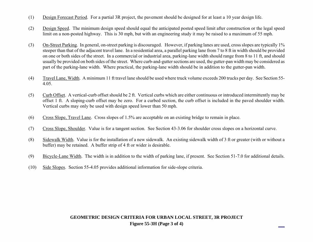
(1) Design Forecast Period. For a partial 3R project, the pavement should be designed for at least a 10 year design life. (2) Design Speed. The minimum design speed should equal the anticipated posted speed limit after construction or the legal speed
limit on a non-posted highway. This is 30 mph, but with an engineering study it may be raised to a maximum of 55 mph. (3) On-Street Parking. In general, on-street parking is discouraged. However, if parking lanes are used, cross slopes are typically 1%
steeper than that of the adjacent travel lane. In a residential area, a parallel parking lane from 7 to 8 ft in width should be provided on one or both sides of the street. In a commercial or industrial area, parking-lane width should range from 8 to 11 ft, and should usually be provided on both sides of the street. Where curb-and-gutter sections are used, the gutter-pan width may be considered as part of the parking-lane width. Where practical, the parking-lane width should be in addition to the gutter-pan width.
(4) Travel Lane, Width. A minimum 11 ft travel lane should be used where truck volume exceeds 200 trucks per day. See Section 55-
4.05. (5) Curb Offset. A vertical-curb offset should be 2 ft. Vertical curbs which are either continuous or introduced intermittently may be
offset 1 ft. A sloping-curb offset may be zero. For a curbed section, the curb offset is included in the paved shoulder width. Vertical curbs may only be used with design speed lower than 50 mph.
(6) Cross Slope, Travel Lane. Cross slopes of 1.5% are acceptable on an existing bridge to remain in place. (7) Cross Slope, Shoulder. Value is for a tangent section. See Section 43-3.06 for shoulder cross slopes on a horizontal curve. (8) Sidewalk Width. Value is for the installation of a new sidewalk. An existing sidewalk width of 3 ft or greater (with or without a
buffer) may be retained. A buffer strip of 4 ft or wider is desirable. (9) Bicycle-Lane Width. The width is in addition to the width of parking lane, if present. See Section 51-7.0 for additional details. (10) Side Slopes. Section 55-4.05 provides additional information for side-slope criteria.
GEOMETRIC DESIGN CRITERIA FOR URBAN LOCAL STREET, 3R PROJECT Figure 55-3H (Page 3 of 4)

(11) Side Slope, Curbed, Cut. A shelf or sidewalk will be present immediately behind the curb before the toe of the backslope. The
minimum width of a shelf desirably should be 6 ft. Where a sidewalk is present, the toe of the backslope will be 1 ft beyond the edge of sidewalk. See Section 45-3.0 for more information.
(12) Width, New or Reconstructed Bridge. See Section 402-6.2(01) for more information. The clear roadway width is the algebraic
sum of the following: a. the approach traveled way width; b. the approach usable shoulder width without guardrail; and c. a bridge-railing offset (see Figure 402-6H). (13) Structural Capacity, Existing Bridge to Remain in Place. For a street with AADT ≤ 50, an HS-10 loading is acceptable. (14) Width, Existing Bridge to Remain in Place. If the width of the existing bridge is less than the approach travelway width, the bridge
should be widened to at least the travelway width. (15) Vertical Clearance, Local Under. Value includes an additional 6 in. allowance for a future pavement overlay. Vertical clearance
applies from usable edge to usable edge of shoulder. (16) Vertical Clearance, Existing Bridge. See Section 55-6.02 for additional information on minimum allowable vertical clearance. (17) Vertical Clearance, Local Over Railroad. See Chapter 402-6.01(03) for additional information on railroad clearance under a
highway. (18) Intersection Sight Distance. For left turn onto a 2 lane road, P = Passenger car; SUT = single unit truck. See Figure 46-10G
for value for a combination truck.
GEOMETRIC DESIGN CRITERIA FOR URBAN LOCAL STREET, 3R PROJECT Figure 55-3H (Page 4 of 4)

Design Speed (mph)
Calculated K Value
(K = V2/46.5)
K Value Rounded For
Design 20 8.6 9 25 13.4 14 30 19.4 20 35 26.3 27 45 43.5 44 50 53.8 54 55 65.1 66 60 77.4 78 70 105.4 106 75 121.0 122
KAAVL ==5.46
2
Where: L = Length of vertical curve, ft. A = Algebraic difference between grades, % K = Horizontal distance required to effect a 1% change in gradient V = Design speed, mph
K VALUE FOR SAG VERTICAL CURVE (Comfort Criteria — 3R Project
Figure 55-4A
2013

2013

Span Rise Treatment ≤ 10 ft All B preferred; A acceptable > 10 ft < 5.5 ft B preferred; A acceptable > 10 ft ≥ 5.5 ft B
A Provide a clear zone with 6:1 slopes or flatter at least a distance LR in advance
of, and 100 ft beyond, the structure. Taper 10:1 on both sides of the structure to tie back in.
B Guardrail should be placed. Use treatment A if guardrail is impractical due to
the close proximity of a public road approach or drive. The drive grade should be designed to be compatible with the clear-zone slope. The drive sideslope should be 10:1.
CLEAR ZONE / GUARDRAIL AT CULVERT
Figure 55-5A(1)
2013

Design Speed, mph
AADT < 1,000
1,000 ≤ AADT < 5,000
5,000 ≤ AADT < 10,000
AADT ≥ 10,000
70 220 260 299 361 60 171 181 210 260 55 151 164 190 237 50 131 151 171 210 45 115 131 151 184 40 99 112 131 161 30 69 79 89 112
RUNOUT LENGTH, LR (ft) FOR RESTRICTIVE CONDITION
Figure 55-5B
2013

Spot, Section, or
Intersection
No. Accidentsin Year No. No.
V No.
I No. F
Accident Codes from IDM Figure 55-8B
ReferenceRoute No. 1 2 3 A B C D E F G
V = Vehicles; I = Injured; F = Fatalities
ACCIDENT ANALYSIS FORM
Figure 55-8A

(A) WEATHER (D) COLLISION INVOLVED:
(E) LOCATION OF FIRST DAMAGE
1 Clear 2 Cloudy 3 Rain 4 Snow 5 Hail or Wintry Mix
1 Animal 2 Animal-Drawn Vehicle 3 Bicycle 4 Bridge Support 5 Building Wall 6 Culvert / Headwall / Drainage Structure 7 Curbing 8 Deer (include quantity) 9 Earth Embankment 10 Fence 11 Fire Hydrant 12 Guardrail or Median Barrier 13 Impact Attenuator 14 Light / Utility Pole 15 Mailbox 16 Other Fixed Object 17 Other Nonfixed Object 18 Other Motor Vehicle 19 Pedestrian 20 Railroad Train 21 Signpost 22 Snow Embankment 23 Traffic Signal 24 Tree
1 Driveway Access 2 Interchange Area 3 Intersection 4 Median 5 Off Roadway 6 Roadway 7 Shoulder
(B) SURFACE CONDITION Required Codes 1 Dry 2 Wet 3 Muddy 4 Slush 5 Snow or Ice
(F) ROAD CHARACTERISTICS 1 Straight and Level 2 Straight and On Grade 3 Straight at Hill Crest 4 Curved and Level 5 Curved and On Grade 6 Curved at Hill Crest
(B) SURFACE CONDITION Optional Codes
6 Sand or Gravel 7 Organic Material 8 Chemicals or Solvents 9 Grain 10 Trash or Debris
(G) COLLISION DIAGRAM 1 Head-On 2 Rear-End 3 Same-Direction Sideswipe 4 Opposite-Direction Sideswipe 5 Off-Road 6 see Figure 55-8C
(C) LIGHT CONDITIONS 1 Daylight 2 Dawn or Dusk 3 Dark, Streetlights On 4 Dark, Streetlights Off 5 Dark, No Streetlights
ACCIDENT-ANALYIS FORM CODES
Figure 55-8B
2013

2013

DRIVER-RELATED Correctable By Safety Enhancement
Not Correctable By Safety
Enhancement Unsafe Speed Sick Failed to Yield R/W Fell Asleep Following Too Close Lost Consciousness Improper Passing Driver Inattention Disregard Traffic Controls Distraction Turning Improperly Physical Disability Alcohol Involvement Drug Involvement
X -- X X X -- X X X X X -- X X
X X X X X X -- X X X X X X X
VEHICLE-RELATED
Brakes Defective Tow Hitch Defective Headlights Defective Over or Improper Load Other Lighting Defects Oversized Load on Vehicle Steering Failure Tire Failure/Inadequate
X -- X -- X -- -- X
X X X X X X X X
ENVIRONMENT-RELATED
Animal on Roadway Holes/Deep Ruts/Bumps Glare Road Under Const. / Maint. View Obstructed/Limited Debris in Roadway Improperly Parked Vehicle(s) Improper/Non-Working Traffic Ctrls. Fixed Object(s) Slippery Surface Shoulders Defective Water Ponding Roadside Hazards
X X X -- X -- X X X X X X X
-- -- X -- X X X X X -- -- -- --
CONTRIBUTING CIRCUMSTANCES
Figure 55-8D
2013

Accident Pattern
Probable Cause
Safety Enhancement
Run-off-roadway
Slippery Pavement Improve skid resistance; provide adequate drainage; groove existing pavement
Roadway Design Inadequate for Traffic Conditions
Widen lanes/shoulders; relocate islands; provide proper super-elevation; install/improve traffic barriers; improve alignment/grade; flatten slopes/ditches; provide escape ramp
Poor Delineation Improve/install pavement markings; install roadside delineators; install advance warning lights
Poor Visibility Improve roadway lighting; increase sign size
Inadequate Shoulder Upgrade roadway shoulders
Improper Channelization Improve channelization
Overturn
Roadside Features
Flatten slopes and ditches; relocate drainage facilities; extend culverts; provide traversable culvert end treatments; install/improve traffic barriers
Inadequate shoulder Widen lane/shoulder; upgrade shoulder surface; remove curbing obstructions; revise cross slope
Pavement Feature Eliminate edge dropoff; improve superelevation/crown
ACCIDENT ANALYSIS
Figure 55-8E
2013

Accident Pattern Probable Cause
Safety Enhancement
Bridges
Alignment Realign bridge/roadway; install advance warning signs; improve delineation/markings
Narrow Roadway Widen structure; improve delineation/markings; install signing/ Signals
Visibility Remove obstruction; install advance warning signs; improve delineation and markings
Vertical Clearance
Rebuild structure/adjust roadway grade; install advance warning signs; improve delineation and markings; provide height restrictor/warning device
Slippery Surface (Wet/Icy) Resurface deck; improve skid resistance; provide adequate drainage; provide special signing
Rough Surface Resurface deck; rehabilitate joints; regrade approaches
Inadequate Barrier
Upgrade bridge rail system; upgrade approach rail/terminals; upgrade bridge - approach rail connections; remove hazardous curb; improve delineation and marking
Parked Vehicles Inadequate Road Design Widen lanes/shoulders
ACCIDENT ANALYSIS
Figure 55-8E (Continued)
2013

3
Accident Pattern
Probable Cause
Safety Enhancement
Fixed Object
Obstructions In or Too Close to Roadway
Remove/relocate obstacles; install breakaway features to light poles, signposts, etc.; protect objects with guardrail; install crash cushions; delineation/reflectorize safety hardware
Inadequate Lighting Improve roadway lighting
Inadequate Pavement Install reflectorized pavement marking lines/raised markers
Inadequate Signs, Delineators and Guardrail
Install reflectorized paint and/or reflectors on the obstruction; add special signing; upgrade barrier system
Inadequate Road Design Improve alignment/grade; provide proper superelevation; install warning signs/delineators; provide wider lanes
Slippery Surface Improve skid resistance; provide adequate drainage; groove existing pavement
Sideswipe or Head-On
Inadequate Road Design
Provide wider lanes; improve alignment/grade; provide passing lanes; provide roadside delineators; sign and mark unsafe passing areas
Inadequate Shoulder Improve shoulders
Excessive Vehicle Speed Install median devices
Inadequate Pavement Markings
Install/improve centerlines, lane lines and edgelines; install reflectorized markers
Inadequate Channelization Install acceleration and deceleration lanes; improve/install channelization; provide turning bays
Inadequate signing Provide advance direction and warning signs; add illuminated name signs
ACCIDENT ANALYSIS
Figure 55-8E (Continued)
2013

Accident Pattern
Probable Cause
Safety Enhancement
Intersection (Signalized/ Unsignalized) Left-Turn, Head-On, Right Angle, Rear End
Large Volume of Left/ Right Turns
Widen road; channelize intersection; install stop signs; provide signal; increase curb radii
Restricted Sight Distance
Remove sight obstructions; provide adequate channelization; provide left/ right turn lanes; install warning signs; install stop signs; install signal; install advance markings to supplement signs; install stop bars
Slippery Surface Improve skid resistance; provide adequate drainage; groove pavement
Large Numbers of Turning Vehicles
Create left- or right-turn lanes; curb radii; install signal
Inadequate Lighting Improve roadway lighting
Lack of Adequate Gaps Provide signal; provide stop signs
Crossing Pedestrians Install/improve signing or marking of pedestrian crosswalks; install signal
Large Total Intersection Volume Install signal; add traffic lane
Excessive Speed on Approaches
Install rumble strips; improve warning devices
Inadequate Advance Warning Signs Install advance warning signs
Inadequate Traffic Control Devices Upgrade traffic control devices
Poor Visibility of Signals
Install/improve advance warning devices; install overhead signals; install 305-mm signal lenses; install visors/back plates; relocate signals; remove sight obstructions; add illuminated/reflectorized name signs
Unwarranted Signals Remove signals
Inadequate Signal Timing Upgrade signal system timing/phasing
ACCIDENT ANALYSIS
Figure 55-8E (Continued)
2013

Accident Pattern
Probable Cause
Safety Enhancement
Access Related
Left-Turning Vehicles Install median devices; install two-way left-turn lanes
Improperly Located Driveway
Move driveway to side street; install curbing to define driveway location; consolidate adjacent driveways
Right-Turning Vehicles Provide right-turn lanes; increase the width of driveways; widen through lanes; increase curb radii
Large Volume of Through Traffic
Move driveway to side street; construct a local service road
Large Volume of Driveway Traffic
Signalize driveway; provide acceleration and deceleration lanes; channelize driveway
Restricted Sight Remove obstructions
Inadequate Lighting Improve street lighting
Nighttime
Poor Visibility or Lighting Install/improve streetlighting; install/improve delineation/markings; install/improve warning signs
Poor Sign Quality Upgrade signing; provide illuminated reflectorized signs
Inadequate Channelization or Delineation
Install pavement markings; improve channelization/delineation
ACCIDENT ANALYSIS
Figure 55-8E (Continued)
2013

Accident Pattern
Probable Cause
Safety Enhancement
Pedestrian/ Bicycle
Limited Sight Distance Remove sight obstructions; install/ improve pedestrian crossing signs and markings
Inadequate Protection Add pedestrian refuge islands
Inadequate Signals/Signs Install/upgrade signals/signs
Mid-block Crossings Install warning signs/markings
Inadequate Pavement Markings
Supplement markings with signing; upgrade pavement markings
Lack of Crossing Opportunity
Install traffic/pedestrian signals; install pedestrian crosswalk and signs
Inadequate Lighting Improve lighting
Excessive Vehicle Speed Install proper warning signs
Pedestrian/Bicycles on Roadway
Install sidewalks; install bike lanes/path; eliminate roadside obstructions; install curb ramps
Long Distance to Nearest Crosswalk
Install pedestrian crosswalk; install pedestrian actuated signals
Wet Pavement
Slippery Pavement Improve skid resistance; groove existing pavement
Inadequate Drainage Provide adequate drainage
Inadequate Pavement Markings
Install raised/reflectorized pavement markings
ACCIDENT ANALYSIS
Figure 55-8E (Continued)
2013

Accident Pattern
Probable Cause
Safety Enhancement
Railroad Crossings
Restricted Sight Distance Remove sight obstructions; reduce grade; install active warning devices; install advance warning signs
Poor Visibility Improve roadway lighting; increase size of signs
Inadequate Pavement Markings
Install advance markings to supplement signs; install stop bars; install/improve pavement markings
Rough Crossing Surface Improve crossing surface
Sharp Crossing Angle Rebuild crossing with proper angle
ACCIDENT ANALYSIS
Figure 55-8E (Continued)
2013