Embed Size (px)
Citation preview

HAL Id: hal-03047844https://hal-normandie-univ.archives-ouvertes.fr/hal-03047844
Submitted on 14 Dec 2020
HAL is a multi-disciplinary open accessarchive for the deposit and dissemination of sci-entific research documents, whether they are pub-lished or not. The documents may come fromteaching and research institutions in France orabroad, or from public or private research centers.
L’archive ouverte pluridisciplinaire HAL, estdestinée au dépôt et à la diffusion de documentsscientifiques de niveau recherche, publiés ou non,émanant des établissements d’enseignement et derecherche français ou étrangers, des laboratoirespublics ou privés.
GeodesicSlicer: a Slicer Toolbox for Targeting BrainStimulation
F. Briend, E. Leroux, C. Nathou, N. Delcroix, S. Dollfus, Olivier Etard
To cite this version:F. Briend, E. Leroux, C. Nathou, N. Delcroix, S. Dollfus, et al.. GeodesicSlicer: a Slicer Toolbox forTargeting Brain Stimulation. Neuroinformatics, Springer, 2020, 18 (4), pp.509-516. �10.1007/s12021-020-09457-9�. �hal-03047844�

1
Title Page
GeodesicSlicer: A Slicer toolbox for targeting brain stimulation
Briend F.a*, Leroux E. a, Nathou C. a, b, Delcroix N. c, Dollfus S. a, b, Etard O. a d.
a Normandie Univ, UNICAEN, ISTS, EA 7466, GIP Cyceron, 14000 Caen, France
b CHU de Caen, Service de Psychiatrie adulte, Centre Esquirol, 14000 Caen, France
c Normandie Univ, UNICAEN, CNRS, CHU de Caen, UMS 3408, GIP Cyceron, 14000 Caen,
France
d CHU de Caen, Service d’Explorations Fonctionnelles du Système Nerveux, 14000 Caen,
France
* Corresponding author : Frédéric Briend, Centre Hospitalier Universitaire, Centre Esquirol,
Caen, F-14000, France. Tel.: +33 231065018; fax: +33 231064987.
E-mail : [email protected]. http://www.ists.cyceron.fr/
Abstract: 196 words
Text: 3596 words
Number of figures: 2 figures
Number of tables: 0 table

2
ABSTRACT
NonInvasive Brain Stimulation (NIBS) is a potential therapeutic tool with growing interest, but
neuronavigation-guided software and tools available for the target determination are mostly
either expensive or closed proprietary applications. To address these limitations, we propose
GeodesicSlicer, a customizable, free, and open-source NIBS therapy research toolkit.
GeodesicSlicer is implemented as an extension for the widely used 3D Slicer medical image
visualization and analysis application platform. GeodesicSlicer uses cortical stimulation target
from either functional or anatomical images to provide functionality specifically designed for
NIBS therapy research. The provided algorithms are tested and they are accessible through a
convenient graphical user interface. Modules have been created for NIBS target determination
according to the position of the electrodes in the 10-20 system electroencephalogram and
calculating correction factors to adjust the repetitive Transcranial Magnetic Stimulation (rTMS)
dose for the treatment. Two illustrative examples are processing with the module. This new
open-source software has been developed for NIBS therapy: GeodesicSlicer is an alternative
for laboratories that do not have access to neuronavigation system. The triangulation-based
MRI-guided method presented here provides a reproducible and inexpensive way to position
the TMS coil that may be used without the use of a neuronavigation system.
Keywords
NIBS, rTMS, 3D Slicer, EEG, target determination, correction factor.

3
Introduction
A key issue in the field of NonInvasive Brain Stimulation (NIBS) is to determine an
accurate localization on the scalp to correctly target cortical areas knowing the great anatomical
variability of the brain. Since personalized medicine for the treatment of psychosis allows for
the consideration of substantial inter-individual variability, recent findings claim that brain
stimulation can be guided in a personalized manner (Briend et al. Under Review; Kraus and
Gharabaghi 2015; Lahti 2016; I. E. Sommer et al. 2018).
Most clinical applications of the NIBS are based on probabilistic targeting methods
which do not account for individual anatomical variability (e.g. for major depressive episodes
the so called “5-cm rule” (U. Herwig et al. 2001) or the International 10–20
electroencephalogram (EEG) (De Witte et al. 2018; Uwe Herwig et al. 2003) or derivative
system (Beam et al. 2009)). This may lead to suboptimal clinical responses when compared to
individualized targeting techniques based on structural brain scanning. Research and clinical
studies require accuracy and precision not offered by these probabilistic targeting methods
(Herbsman and Nahas 2011). For example, a common and easy method for the positioning of
the coil in psychiatric therapies uses the standardized T3P3 site according to the International
10–20 system of EEG electrode positioning (Jasper 1958). However, this method is known to
be an inaccurate estimation, especially given its variable projections on the individual brain
(Briend et al. Under Review; Uwe Herwig et al. 2003). It is why, there is a need for personalized
target method that uses the participant’s own anatomical or functional images to guide target
placement.
As a personalized target method, the combination of brain imaging and a
neuronavigation system in the field of NIBS may improve the efficacy of stimulation treatment
(U. Herwig et al. 2001; I. E. Sommer et al. 2018; I. E. C. Sommer et al. 2007), however, there
are some disadvantages. These include the high cost of these systems, which can exceed

4
$50,000, the complexity to use, the space consumed by the device and the difficulty in using
these systems for the study of posterior brain areas located in the blind spot of the
neuronavigation system (Vaghefi et al. 2015).
In order to propose an alternative that can combine the accuracy and the simplicity of
the two previous methods, we developed an open-source tool “GeodesicSlicer”, which
facilitates the stimulation site determination, allowing users to manually posit the target of
repetitive Transcranial Magnetic Stimulation (rTMS) coil over a cortical target derived from
functional or anatomical images. This module creates a 3D mesh morphed to the structural MRI
head data of the participant then projected an individualized 10-20 system EEG and the cortical
stimulation target on it. Then, the module calculates the geodesic distances between the
projected stimulation target and the position of the 3 nearest electrodes in the individualized
10-20 system EEG in order to guide the stimulation. Our technique takes triangulation-based
MRI-guided method as Andoh et al. (Andoh et al. 2009) that devised a method of targeting
NIBS using an anatomical scan only. Moreover, it was proposed that rTMS inter-individual
variability in its efficacy for treating patient could be attributed to variations in the cortical
anatomy in Schizophrenia (Ralph E. Hoffman et al. 2013) or in major depression disorders
(MDD) (Trojak et al. 2012). It is why, we implemented in this module, correction factors,
according to scalp-to-cortex distance (Summers and Hanlon 2017), to adjust the rTMS dose for
the treatment.
We propose GeodesicSlicer as a common easy-to-use software for NIBS site
determination, thanks to its implementation in 3D Slicer, a powerful tools for neuroimaging
(Pieper et al. 2006).
Methods and materials
Implementation of GeodesicSlicer

5
Platform
Geodesic Slicer was implemented in 3D Slicer (Pieper et al. 2006), a software which is
freely downloadable from the website http://www.slicer.org. 3D Slicer provides an immense
amount of functionality to visualize and analyze a wide range of datasets, such as
anatomical/functional images, image segmentation results and surface models. Also, it supports
import and export data from a wide range of standard data formats. In addition, the 3D Slicer
has a widespread use in project research and is more and more downloaded (Pinter et al. 2012).
Implementation
The GeodesicSlicer module is written in Python. Python is a very popular and easily
interpreted language, which allows multiple programming paradigms, including object-
oriented, imperative and functional programming styles. Inheriting from 3D Slicer,
GeodesicSlicer is available for Windows, Linux, and Mac OS X platforms.
Our implementation of the algorithm in 3D Slicer consists of a graphical user interface
front-end to enable interactions of the user with the image and several algorithms back-end. It
allows the generations of head surface mesh reconstruction and individualized 10-20 system
EEG. Moreover, it can compute the geodesic distances between the target and electrodes
landmarks and compute 2 correction factors to adjust rTMS dose for the treatment.
The geodesic distances (i.e. the shortest path between two points in a curved space) to
draw the individualized 10-20 system EEG or compute the distances between the target and
electrodes landmarks are calculated on a 3D mesh morphed to the structural MRI head data of
the participant thanks to the implemented Dijkstra's algorithm (Dijkstra 1959), which calculates
the shortest path between the vertex of triangle mesh.
Two correction factors to adjust rTMS dose for the treatment for individual subjects are
given by the software. First, Stokes et al. (Stokes et al. 2007), proposed increasing the

6
stimulation intensity by about 3% for each additional millimeter between the coil and the scalp
surface. Second, Hoffman et al. (Ralph E. Hoffman et al. 2013) also take into account of the
skin-surface-to-cortical-surface, but their adjustment also reflected the fact that magnetic field
strength falls off exponentially relative to distance to the center of the coil (supplementary
material of their article). These corrections factors are, for Stokes et al. (Stokes et al. 2007),
where [AdjMT% = 2,7*(SCDx - SCDm) + rMT] and according to Hoffman et colleagues
(Ralph E. Hoffman et al. 2013), where [AdjMT% = 0.90*rMT*e0.036*(SCDx-SCDm)], where
AdjMT is the adjusted motor threshold in percent (%), rMT is the unadjusted resting motor
threshold in % of stimulator output, SCDx is the scalp-to-cortex distance between the scalp and
the cortical stimulation site and SCDm is the scalp-to-cortex distance between the scalp and the
primary motor cortex (M1).
Licensing and distribution
GeodesicSlicer (WikiPage) is distributed under a CeCill license. The software may be
used not only for research purposes but also in clinical and commercial projects. Note, however,
that validation for a particular clinical purpose is an onus of the user. The brain stimulation
guidelines and safety procedures are dependent on each neurostimulation therapy used [for
example in TMS: (Rossi et al. 2009)], but not directly to the use of this software.
GeodesicSlicer modules can be downloaded as an extension for 3D Slicer 4.10.0 or
higher. All the presented software is open-source and the source code is available on GitHub,
which contains detailed guides for user’s installation and usage. The authors declare that they
have no conflict of interest.
GeodesicSlicer, a MRI-guided method
First, GeodesicSlicer provides realistic and accurate 3D representations of the head
scalp. The, the MRI-guided method uses participant’s individual MRI to determine the TMS
coil position onto the head surface. We describe in the following section the workflow of
7
GeodesicSlicer to position the TMS coil over the participant’s head surface from her/his T1-
weighted anatomical/functional images.
Procedure of GeodesicSlicer
1) Loading of the T1-weighted image into 3D Slicer.
2) 3D representation of the head (the head surface mesh or more accurately, triangle
meshes) was individually reconstructed in native space from the T1-weighted whole-
brain anatomical image using 3D Slicer software (“editor toolbox” version 4.8).
3) Manual identification of four anatomical landmarks for the essential positioning of the
electrodes on the head surface mesh: the nasion, the inion, the left and right tragi (in this
order). The Dijkstra's algorithm automatically reconstructed the 10-20 system EEG with
T3P3 in the middle of the segment delimited by T3 and P3. For that, the shortest paths
between the nasion and inion and the left and right tragi that passed through the center
point of the head (electrode Cz). Then, always with the shortest path algorithm, all
electrodes are located according to their standardized that represent proportions of the
measured distance from the nasion to the inion and from the left to the right tragi (Klem
et al. 1999).
4) Manual placement of the cortical stimulation target on the T1-weighted image, the
projection of it onto the head surface mesh was made by using a classical 3D Euclidean
distance, i.e. √ (x2−x1)² + (y2−y1)² + (z2−z1)².
5) The fifth step was the computation of the geodesic distances between this projected
target on the surface and the electrodes of the 10-20 system EEG corresponding of the
participant’s head. These three distances (in cm) were then used to triangulate and to
position the TMS coil manually over the participant’s head.
6) The last step is needed to adjust the rTMS dose for treatment. After placing cortical
landmark in M1 according to the Yousry’s method (Yousry et al. 1997), the brain area

8
to determine the motor threshold in rTMS, and giving rMT of stimulator output, the
software gives two AdjMT of stimulator output.
The duration of this workflow lasted about 10 minutes per participant.
Illustrative Examples Using GeodesicSlicer
Use cases are presented to demonstrate the capabilities of GeodesicSlicer extension for
addressing clinically relevant rTMS site determination. We chose brain imaging data of two
patients from previous study of our team (Dollfus et al. 2018), but the rTMS stimulation
proposed here is just theoretical. The subjects have previously written informed consent and
these studies were approved by a local ethical committee. All coordinates are given in the MRI
native space.
Accuracy of the measure
Eight controls (35.77 ± 5.29 years; 2 women) were included to assess the validity of the
GeodesicSlicer method. The placement of the nasion, inion, and the two tragi determines the
position of the electrodes in the 10-20 system EEG. We measured the distances from the nasion
to the inion and from the left tragus and the right tragus in the controls with a measuring tape
and compared them to the same distances calculated by GeodesicSlicer. Bland–Altman plots
assess retest reliability of two measures and were used to test the stability across these distances
(Bland and Altman 1999).

9
Results
Illustrative Examples Using GeodesicSlicer
Case 1: Determination of the projected stimulation target in one patient with
schizophrenia with auditory verbal hallucinations
The rTMS can be used as treatment for auditory verbal hallucinations (AVHs), notably,
in the case of refractory to treatments (R. E. Hoffman et al. 1999). In the case described below,
we will consider that patient receive a treatment by rTMS applied over a precise anatomical site
in the left temporal region, that significant effects in AVH reduction.
The patient is a 35-year-old man, diagnosed with schizophrenia (based on the DSM-V,
Diagnostic and Statistical Manual of Mental Disorder 5th edition) and who suffers of constant
AVHs. He was recruited from the University Hospital (Caen, France).
rTMS site determination
The patient underwent a structural MRI on a 3T scanner (Intera Achieva 3T, Philips
Medical System, the Netherlands) with a three-dimensional (3D), high-resolution T1-weighted
structural volume (T1 TFE sequence, 256 x 256 matrix size with 180 contiguous slices, field of
view (FOV) = 256 mm, 1 mm isotropic resolution, antero-posterior slice orientation, repetition
time = 6.914 ms, echo time = 3.16 ms, flip angle = 6, inversion time = 940 ms).
Using this system, the cortical stimulation target was localized at the crossing between
the projection of the ascending branch of the left lateral sulcus and the left superior temporal
sulcus. To do that, using a sagittal section of the structural MRI to visualize the upper sylvian
and temporal sulcus, we propose to consider the intersection between the orthogonal projection
of the verticalization of the Sylvius fissure and the upper left temporal sulcus (see
Supplementary Data Video 1 in (Dollfus et al. 2018)).
GeodesicSlicer results

10
After the different steps from GeodesicSlicer described above , the results are described
below (see Fig. 1). The 10-20 system EEG electrodes were generated after determining the
nasion (x = -0.87, y = 111.20, z =-22.57), the inion (x = 8.30, y = -101.80, z =-37.17), the left
pre-auricular (x = -76.31, y = 7.92, z =-42.99) and the right pre-auricular (x = 4.30, y = 22.20,
z =-47.49) on the head surface mesh. After placing the cortical stimulation target on the
patient’s T1- weighted anatomical image (x = -40.66, y = -23.26, z = 3.57, corresponding to the
superior temporal sulcus), the stimulation target was projected on his head surface mesh. We
then obtained the following 3 nearest electrodes around projected stimulation target and their
geodesic distance (in cm) with the projected stimulation target: Electrode 1: T3 at 3.65,
electrode 2: T5 at 4.47 and electrode 3: C3 at 8.39. These three distances were then used to
triangulate and to position the TMS coil manually over the patient’s head.
After placing M1 on the patient’s T1 anatomical image (x = -30.92, y = -11.77, z =52.58)
and choosing the stimulation intensity of the resting motor threshold (rMT) by default (100%),
we found the SCDx = 3.34 cm, and SCDm = 3.09 cm and the following two AdjMT (in %
stimulator): according to Strokes (Stokes et al. 2007): 107.22 and according to Hoffman (Ralph
E. Hoffman et al. 2013): 98.75.
Case 2: Determination of the projected stimulation target in one patient with major
depressive disorder
The rTMS can also be used as treatment for MDD that represent one of the most
common psychiatric diseases with a prevalence in the general population general of 10-15%. A
large number of depressed patients are resistant to drug treatment and, actually, the rTMS is
proving to be the greatest therapeutic efficacy (McGirr et al. 2015). In the case described below,
we will consider that patient could, for example, receive a treatment by rTMS in stimulating a
key region involved in the MDD: the left dorsolateral prefrontal (DLPFC) (McGirr et al. 2015).

11
The patient is a 63-year-old woman, diagnosed with MDD (based on the DSM-V,
Diagnostic and Statistical Manual of Mental Disorder 5th edition). She was recruited from the
University Hospital (Caen, France) and realized cerebral MRI on a 3T scanner in the same way
that in the Case 1.
rTMS site determination
Using the structural MRI, after determining the position of the upper frontal sulcus and
the lower frontal sulcus, the target can be defined as being equidistant from the upper and
lower frontal sulcus in the coronal plane which crosses the anterior extremity of the temporal
pole.
GeodesicSlicer results
The results from GeodesicSlicer are described below (see Fig. 2). The 10-20 system
EEG electrodes were generated after determining the nasion (x = -3.65, y = 97.45, z = -5.77),
the inion (x = -3.14, y = -89.86, z = -16.90), the left pre-auricular (x = -78.02, y = 2.93, z = -
14.58) and the right pre-auricular (x = 71.20, y = 2.88, z = -14.87) on the head surface of mesh.
After placing the cortical stimulation target on the patient’s T1-weighted anatomical image (x
= -37.62, y = 40.13, z = 55.85, corresponding to the patient’s DLPFC), the stimulation target
was projected on his head surface (x = -54.22, y = 49.50, z = 66.96). Then, we obtained the
following 3 nearest electrodes around projected stimulation target and their geodesic distance
(in cm) with the projected stimulation target: Electrode 1: F3 at 2.30, electrode 2: F7 at 3.73
and electrode 3: C3 at 4.03. With this these three distances, after triangulation, it could be
possible to position the TMS coil manually over the patient’s head.
After placing M1 area on the patient’s T1 anatomical image (x = -32.49, y = -3.51, z =
71.66) and have choose the stimulation intensity of the rMT by default (100%), we found SCDx
= 22.06 cm, and SCDm = 25.37 cm and the following two AdjMT% (in % stimulator):

12
according to Strokes (Stokes et al. 2007): 90.73 and according to Hoffman (Ralph E. Hoffman
et al. 2013): 79.88.
Accuracy of the measure
The limits of agreement of Bland–Altman plots of the nasion-inion distances were from
−0.82 to 1.96 cm, with a mean difference of 0.57 ± 0.70 cm (range, −0.64 to 1.59 cm), and from
−0.52 to 1.82 cm for the tragus-tragus with a mean difference of 0.65 ± 0.59 cm (range, −0.16
to 1.53 cm), showing that the reliability between the geodesic distances was consistent between
those calculated by GeodesicSlicer and the manual measures.

13
Discussion
Personalized and guided stimulation (Fox et al. 2013; I. E. Sommer et al. 2018) seems
to be an efficient way to improve the discrepant efficacy results previously reported in NIBS
studies (Briend et al. Under Review). In this context, we developed GeodesicSlicer, a novel
MRI-guided method using individual brain imagery to position the TMS coil reliably on the
participant’s head. GeodesicSlicer aims to become a complete and easy-to-use toolkit for
stimulation researchers by providing accurate target according to 10-20 system EEG electrode
positioning and a correction factor to adjust the rTMS dose for the treatment.
In comparison with neuronavigation system, the current method may have some
advantages because it is relatively inexpensive and does not require any additional experimental
setting. In addition, the MRI-guided method could be particularly useful for therapeutic
protocols, because the result of the software allows easy targeting of the same stimulation site
across multiple sessions and in multicenter trials, as the three distances can be used offline to
position the TMS coil (Andoh et al. 2009). Moreover, it only needs 3D Slicer, a software freely
available online and is relatively user-friendly.
Previous studies have calculated geodesic distances between scalp landmarks using
surface mesh representations of the head in order to guide NIBS (Andoh et al. 2009). Others
have worked on the head surface mesh with vectors linking key anatomical landmarks drawn
on the mesh and used it to calculate the precise distances on the scalp corresponding to these
vectors (Vaghefi et al. 2015). Just one study has used a semi-automatic approach to generate
the 10–20 system EEG correlates external skull locations (Xiao et al. 2017), but no study has
combined triangulation system based on individualized 10-20 system EEG that morphed to the
head surface mesh reconstruction of participant.
Others teams have developed a feasible low-cost solution to track coil positions during
rTMS procedures, but the setup and run of the clinical experiment are time-consuming

14
processes (Dayan et al. 2016; Rodseth et al. 2017; Washabaugh and Krishnan 2016). Although,
our method that adjusts the 10–20 system EEG for the participant's skull size, conversely to
other (Beam et al. 2009), have the benefit of taking into account differences in cortical anatomy
or skull sizes between each individual in a quick and low-cost way. This triangulation-based
MRI-guided method is an alternative to more complicated and costly stereotaxic targeting
paradigms. In addition, this software package could be useful for laboratories that do not have
access to neuronavigation system.
Limitations and Future Works
Our module has some limitations caused by the method itself. First, unlike probabilistic
targeting techniques, Geodesic Slicer requires brain imaging. Indeed, MRI scanning is
expensive and not always available in many institutes (Xiao et al. 2017), but this personalized
method using MRI with the participant’s own anatomical or functional images to guide is very
accurate (Briend et al. Under Review; Kraus and Gharabaghi 2015; Lahti 2016; I. E. Sommer
et al. 2018).
Second this method faces problems in time cost, mainly due to the manual positioning
of the international 10–20 system EEG and the measurement procedure (Xiao et al. 2017).
However by its facilitating approaches for rTMS target localization, the International 10–20
system of EEG represents the gold standard in clinical uses (Uwe Herwig et al. 2003).
Third, as Andoh and colleagues already mentioned (Andoh et al. 2009), the current
MRI-guided method is not a neuronavigation system and therefore cannot provide online
monitoring such as a real-time control of the coil angle. However, it is noteworthy that the
influence of the coil angle remains debated (Niyazov et al. 2005).
Despite these limitations, there are several areas for future work. In particular, some
steps of the MRI-guided method workflow under 3D Slicer can be automated as the landmarks

15
placement including the nasion, the inion and the left and the right tragi. Moreover, the path
precision calculated by the Dijkstra's algorithm produces “jagged” lines depends on the length
of the triangle edges determined during the mesh creation. Further development of
GeodesicSlicer should include these issues to resolve this possible variability, by adding a
smoothing procedure that fitted the Dijkstra's algorithm path (Vaghefi et al. 2015).
Moreover, we did not assess the effectiveness of this costless method against neuronavigation
on the one hand and on the other hand about the effectiveness of correction factors to adjust
rTMS dose. The goal of this paper was to test the measurement accuracy of this software, but
further studies with larger samples will be necessary to determine the clinical benefit of this
method. Although, one paper that use triangulation-based MRI-guided method (Andoh et al.
2009) has already show the accuracy of it.
Conclusions
In summary, Geodesic Slicer is an alternative to the time-consuming process of
neuronavigation system. The triangulation-based MRI-guided method presented herein
provides a reproducible and inexpensive way to position the TMS coil that may be used in case
of unavailability of online neuronavigation, for instance, in a clinical setting. This MRI-guided
method can use cortical landmarks from all MRI scans.

16
Figure with captions
Fig. 1. Results of GeodesicSlicer in a patient with schizophrenia with auditory verbal
hallucinations. 1. Representation of patient’s head surface mesh generate by Geodesic Slicer
with the nasion, inion and the left pre-auricular in turquoise, placed to generate the 10-20
system EEG in red. The stimulation target is then projected onto the head surface mesh (in
blue) and localized near these three nearest electrodes with their geodesic distances: Here, the
electrodes T3, T5 and C3. These three distances were then potentially used to triangulate and
to position the TMS manually over the subject’s head. 2. Views sagittal, coronal and axial of
the cortical (in red) and projected (in blue) stimulation target. 3. Views sagittal, coronal and
axial of the M1 area (in green).

17
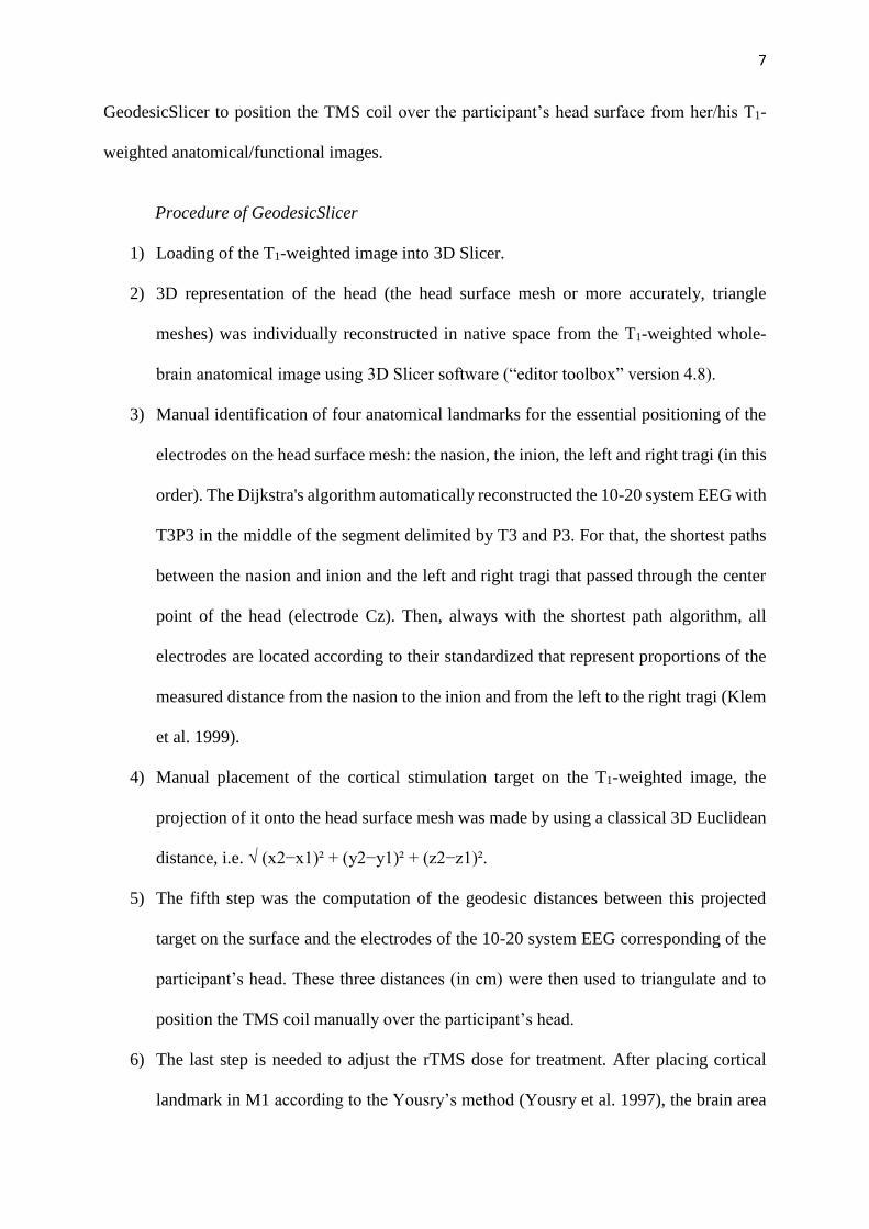
Fig. 2. Results of GeodesicSlicer in a patient with major depressive disorder. 1. Representation of patient’s head surface mesh generate by GeodesicSlicer with the nasion and
the left pre-auricular in turquoise, notably placed to generate the 10-20 system EEG in red.
The stimulation target is then projected onto the head surface mesh (in blue) and localized near
these three nearest electrodes with their geodesic distances: Here, the electrodes F3, F7 and
C3. In brain stimulation session, these three distances could be used to triangulate and to
position the TMS manually over the patient’s head. 2. Views sagittal, coronal and axial of the
cortical stimulation target (in red). 3. Views sagittal, coronal and axial of the M1 area (in
green).

18
Information Sharing Statement: GeodesicSlicer has been put into a toolbox and can be
download as an extension of 3D Slicer or directly from Github.
The available implementation was uncoupled from the ethics protected image data used in the
case studies. One brain imaging data example can be downloaded here. However, clinical data
might be obtained upon request by contacting the corresponding author.
Acknowledgement: The authors would like to thank Drs A. Lasso and K. Yoshimi as well as
A. Nourry for their valuable help in 3D Slicer and VTK library, and William P. Armstrong for
the English rereading.
Conflict of interest: The authors have no conflict of interest to declare.
Funding source: This work was supported by the French Health Ministry (Programme
Hospitalier de Recherche Clinique), the Fondation Fondamentale, the Association Perceneige,
the Region Normandie and the University Caen Normandie.

19
References
Andoh, J., Riviere, D., Mangin, J. F., Artiges, E., Cointepas, Y., Grevent, D., et al. (2009). A
triangulation-based magnetic resonance image-guided method for transcranial
magnetic stimulation coil positioning. Brain Stimul, 2(3), 123–31.
https://doi.org/10.1016/j.brs.2008.10.002
Beam, W., Borckardt, J. J., Reeves, S. T., & George, M. S. (2009). An efficient and accurate
new method for locating the F3 position for prefrontal TMS applications. Brain
stimulation, 2(1), 50–54. https://doi.org/10.1016/j.brs.2008.09.006
Bland, J. M., & Altman, D. G. (1999). Measuring agreement in method comparison studies.
Statistical Methods in Medical Research, 8(2), 135–160.
Briend, F., Nathou, C., Delcroix, N., Dollfus, S., & Etard, O. (Under Review). A new toolbox
to compare target localizations for non-invasive brain stimulation: An application of
rTMS treatment for auditory hallucinations in schizophrenia. Schizophrenia Research.
Dayan, E., Thompson, R. M., Buch, E. R., & Cohen, L. G. (2016). 3D-printed head models
for navigated non-invasive brain stimulation. Clinical Neurophysiology: Official
Journal of the International Federation of Clinical Neurophysiology, 127(10), 3341–
3342. https://doi.org/10.1016/j.clinph.2016.08.011
De Witte, S., Klooster, D., Dedoncker, J., Duprat, R., Remue, J., & Baeken, C. (2018). Left
prefrontal neuronavigated electrode localization in tDCS: 10–20 EEG system versus
MRI-guided neuronavigation. Psychiatry Research: Neuroimaging, 274, 1–6.
https://doi.org/10.1016/j.pscychresns.2018.02.001
Dijkstra, E. W. (1959). A note on two problems in connexion with graphs. Numerische
Mathematik, 1(1), 269–271. https://doi.org/10.1007/BF01386390
Dollfus, S., Jaafari, N., Guillin, O., Trojak, B., Plaze, M., Saba, G., et al. (2018). High-
Frequency Neuronavigated rTMS in Auditory Verbal Hallucinations: A Pilot Double-

20
Blind Controlled Study in Patients With Schizophrenia. Schizophrenia Bulletin, 44(3),
505–514. https://doi.org/10.1093/schbul/sbx127
Fox, M. D., Liu, H., & Pascual-Leone, A. (2013). Identification of reproducible
individualized targets for treatment of depression with TMS based on intrinsic
connectivity. NeuroImage, 66, 151–160.
https://doi.org/10.1016/j.neuroimage.2012.10.082
Herbsman, T., & Nahas, Z. (2011). Anatomically based targeting of prefrontal cortex for
rTMS. Brain Stimulation, 4(4), 300–302. https://doi.org/10.1016/j.brs.2011.01.004
Herwig, U., Padberg, F., Unger, J., Spitzer, M., & Schönfeldt-Lecuona, C. (2001).
Transcranial magnetic stimulation in therapy studies: examination of the reliability of
“standard” coil positioning by neuronavigation. Biological Psychiatry, 50(1), 58–61.
Herwig, Uwe, Satrapi, P., & Schönfeldt-Lecuona, C. (2003). Using the international 10-20
EEG system for positioning of transcranial magnetic stimulation. Brain Topography,
16(2), 95–99.
Hoffman, R. E., Boutros, N. N., Berman, R. M., Roessler, E., Belger, A., Krystal, J. H., &
Charney, D. S. (1999). Transcranial magnetic stimulation of left temporoparietal
cortex in three patients reporting hallucinated “voices.” Biological Psychiatry, 46(1),
130–132.
Hoffman, Ralph E., Wu, K., Pittman, B., Cahill, J. D., Hawkins, K. A., Fernandez, T., &
Hannestad, J. (2013). Transcranial magnetic stimulation of Wernicke’s and right
homologous sites to curtail “voices:” a randomized trial. Biological psychiatry, 73(10),
1008–1014. https://doi.org/10.1016/j.biopsych.2013.01.016
Jasper, H. (1958). The ten twenty electrode system of the international federation.
Electroencephalography and Clinical Neurophysiology, 10, 371–375.

21
Klem, G. H., Lüders, H. O., Jasper, H. H., & Elger, C. (1999). The ten-twenty electrode
system of the International Federation. The International Federation of Clinical
Neurophysiology. Electroencephalography and Clinical Neurophysiology.
Supplement, 52, 3–6.
Kraus, D., & Gharabaghi, A. (2015). Projecting Navigated TMS Sites on the Gyral Anatomy
Decreases Inter-subject Variability of Cortical Motor Maps. Brain Stimulation, 8(4),
831–837. https://doi.org/10.1016/j.brs.2015.03.006
Lahti, A. C. (2016). Making Progress Toward Individualized Medicine in the Treatment of
Psychosis. The American Journal of Psychiatry, 173(1), 5–7.
https://doi.org/10.1176/appi.ajp.2016.15101320
McGirr, A., Van den Eynde, F., Tovar-Perdomo, S., Fleck, M. P. A., & Berlim, M. T. (2015).
Effectiveness and acceptability of accelerated repetitive transcranial magnetic
stimulation (rTMS) for treatment-resistant major depressive disorder: an open label
trial. Journal of Affective Disorders, 173, 216–220.
https://doi.org/10.1016/j.jad.2014.10.068
Niyazov, D. M., Butler, A. J., Kadah, Y. M., Epstein, C. M., & Hu, X. P. (2005). Functional
magnetic resonance imaging and transcranial magnetic stimulation: Effects of motor
imagery, movement and coil orientation. Clinical Neurophysiology, 116(7), 1601–
1610. https://doi.org/10.1016/j.clinph.2005.02.028
Pieper, S., Lorensen, B., Schroeder, W., & Kikinis, R. (2006). The NA-MIC Kit: ITK, VTK,
pipelines, grids and 3D slicer as an open platform for the medical image computing
community. In 3rd IEEE International Symposium on Biomedical Imaging: Nano to
Macro, 2006. (pp. 698–701). Presented at the 3rd IEEE International Symposium on
Biomedical Imaging: Nano to Macro, 2006.
https://doi.org/10.1109/ISBI.2006.1625012

22
Pinter, C., Lasso, A., Wang, A., Jaffray, D., & Fichtinger, G. (2012). SlicerRT: radiation
therapy research toolkit for 3D Slicer. Medical Physics, 39(10), 6332–6338.
https://doi.org/10.1118/1.4754659
Rodseth, J., WashaBaugh, E. P., & Krishnan, C. (2017). A Novel Low-Cost Approach for
Navigated Transcranial Magnetic Stimulation. Restorative neurology and
neuroscience, 35(6), 601–609. https://doi.org/10.3233/RNN-170751
Rossi, S., Hallett, M., Rossini, P. M., Pascual-Leone, A., & Safety of TMS Consensus Group.
(2009). Safety, ethical considerations, and application guidelines for the use of
transcranial magnetic stimulation in clinical practice and research. Clinical
Neurophysiology: Official Journal of the International Federation of Clinical
Neurophysiology, 120(12), 2008–2039. https://doi.org/10.1016/j.clinph.2009.08.016
Sommer, I. E. C., de Weijer, A. D., Daalman, K., Neggers, S. F., Somers, M., Kahn, R. S., et
al. (2007). Can fMRI-guidance improve the efficacy of rTMS treatment for auditory
verbal hallucinations? Schizophrenia Research, 93(1–3), 406–408.
https://doi.org/10.1016/j.schres.2007.03.020
Sommer, I. E., Kleijer, H., & Hugdahl, K. (2018). Toward personalized treatment of
hallucinations. Current Opinion in Psychiatry, 31(3), 237–245.
https://doi.org/10.1097/YCO.0000000000000416
Stokes, M. G., Chambers, C. D., Gould, I. C., English, T., McNaught, E., McDonald, O., &
Mattingley, J. B. (2007). Distance-adjusted motor threshold for transcranial magnetic
stimulation. Clinical Neurophysiology, 118(7), 1617–1625.
https://doi.org/10.1016/j.clinph.2007.04.004
Summers, P. M., & Hanlon, C. A. (2017). BrainRuler-a free, open-access tool for calculating
scalp to cortex distance. Brain stimulation, 10(5), 1009–1010.
https://doi.org/10.1016/j.brs.2017.03.003

23
Trojak, B., Meille, V., Chauvet-Gelinier, J.-C., & Bonin, B. (2012). Does the intensity of
transcranial magnetic stimulation need to be adjusted to scalp-cortex distance? The
Journal of Neuropsychiatry and Clinical Neurosciences, 24(2), E13.
https://doi.org/10.1176/appi.neuropsych.11050114
Vaghefi, E., Cai, P., Fang, F., Byblow, W. D., Stinear, C. M., & Thompson, B. (2015). MRI
Guided Brain Stimulation without the Use of a Neuronavigation System. BioMed
Research International, 2015, 647510. https://doi.org/10.1155/2015/647510
Washabaugh, E. P., & Krishnan, C. (2016). A low-cost system for coil tracking during
transcranial magnetic stimulation. Restorative Neurology and Neuroscience, 34(2),
337–346. https://doi.org/10.3233/RNN-150609
Xiao, X., Zhu, H., Liu, W.-J., Yu, X.-T., Duan, L., Li, Z., & Zhu, C.-Z. (2017). Semi-
automatic 10/20 Identification Method for MRI-Free Probe Placement in Transcranial
Brain Mapping Techniques. Frontiers in Neuroscience, 11, 4.
https://doi.org/10.3389/fnins.2017.00004
Yousry, T. A., Schmid, U. D., Alkadhi, H., Schmidt, D., Peraud, A., Buettner, A., & Winkler,
P. (1997). Localization of the motor hand area to a knob on the precentral gyrus. A
new landmark. Brain: A Journal of Neurology, 120 ( Pt 1), 141–157.