Embed Size (px)
Citation preview

MAZDA MOTOR CORPORATION Hiroshima Head Office 3-1 Shinchi, Fuchu-cho, Aki-gun, Hiroshima 730-8670
97107604
GENUINE WIRELESS CHARGER
INSTALLATION AND USER’S INSTRUCTIONS
Thank you for purchasing a Genuine Mazda Accessory. Before removal and installation, Please thoroughly read these instructions. For your safety, please read the contents of this booklet to properly install and use the wireless charger. Keep these instructions with your vehicle records for future reference.
There are several and sections in this booklet concerning safety when installing or removing the wireless charger. Always read and follow the instructions in order to prevent injuries, accidents, and possible damage to the vehicle.
: Indicates a situation in which serious injury or death could result if the warning is ignored.
: Indicates a situation in which bodily injury or damage to the vehicle could result if the caution is ignored.
For areas indicating the tightening torque in this instruction manual, tighten to the specified torque by using a torque wrench. For areas in which the tightening torque is indicated inside parentheses ( ), the tightening torque is indicated as a reference value, however tightening using a torque wrench is not necessary.
Do not modify the wireless charger. Do not install the wireless charger in any way other than described in the following instructions. If in doubt, please contact your Mazda dealer to install the accessory in order to prevent errors in installation. If you have any questions about the use of the accessory, ask your Mazda dealer for proper advice before using it. Mazda and its suppliers are not responsible for injuries, accidents, and damage to persons and property that arise
from the failure of the dealer or installer to follow these instructions. To ensure safety and reliability of the work, installation, removal and disposal work must be carried out by an
Authorized Mazda Dealership. Be careful not to lose removed parts, and be sure that they are kept free of dirt, scratches, or damage.
PART NAME: WIRELESS CHARGER PART NUMBER: DFR5 V7 440 (2WD)
DFR9 V7 440 (4WD)
VEHICLE: MAZDA CX-30
To the dealer Please turn over these instructions to the customer after installation. To the customer Keep these instructions after installation. The instructions may be necessary for installing
other optional parts or removal of this accessory. Should the vehicle or this accessory be resold, Always transfer these instructions to the
next owner.
For North America
NOTE

2
Wireless Charger DFR5 V7 440 (2WD) Part Part name Qty Part Part name Qty
Wireless charger unit 1
Wireless charger tray 1
Harness 1
Electro tap 2
Urethane tape (100×30mm)
7
Tie wrap (L=150mm) 5
Installation instructions 1
Installation inspection sheet
1
Owner's manual 1
Wireless Charger DFR9 V7 440 (4WD) Part Part name Qty Part Part name Qty
Wireless charger unit 1
Wireless charger tray 1
Harness 1
Electro tap 2
Urethane tape (100×30mm)
7
Tie wrap (L=150mm) 5
Installation instructions 1
Installation inspection sheet
1
Owner's manual 1
1. PARTS
Verify that the kit includes all the following parts and that the parts are not dirty, scratched, or damaged. NOTE

3
2. INSTALLATION VIEW
Electro tap
Harness
Fuse
Wireless charger unit
Electro tap

4
REQUIRED TOOLS ☆Phillips screwdriver ☆Torque wrench ☆Socket wrench ☆Ratchet ☆Wrench or Glasses wrench ☆Fastener remover ☆Tape-wrapped flathead screwdriver ☆Remover tool ☆Plier ☆Nipper ☆Tape-wrapped L shape tools (2mm) ☆Flat file ☆Ultrasonic cutter ☆Cutter ☆Tape-wrapped wire (2mm) ☆Scissors ☆Scale
OTHER PREPARATIONS ☆Metal plate or wooden board ☆Soft clean cloth ☆Mat ☆Protective tape ☆Soapy water ☆Protective glove ☆IPA (Isopropyl alcohol)
To perform the installation work safely and maintain functionality and quality, thoroughly read these instructions before
performing the procedures and always heed the warnings and precautions. In the work procedures, there are descriptions which are only indicated in the illustrations. Make sure to follow these procedures
as well.
WARNING When the negative battery is connected during operation, may cause electric shock or other personal injuries. Disconnect the negative cable before /installation.
Before performing any work, park the vehicle on level ground, apply the parking brake securely, and then block the wheels.
Be careful when handling drills and other sharp objects. If not handled properly, it could result in serious injury.
When connecting/dis- connecting connectors, grasp the connectors, not the wires. Otherwise a short, and an accident from poor contact or fire may occur.
Make sure the connector is securely pressed in until a click sound is heard. Otherwise, a fire or other accident may occur due to an open circuit or poor contact.
Secure the harness with the band (part included) so it doesn’t dangle. If not, it may cause a short, accident, or fire.
Do not pull the harness with excessive force. Doing so can cause a breakage or a short-related accident, as well as an electrical short or fire.
CAUTION
Using improper tools may cause damage and/or broken parts. Use the correct tool for the job.
Wrap protective tape around screwdrivers and fastener remover tools to prevent scratching the vehicle.
Excessive length of tie wrap may interfere with other parts and cause damage.
Put the removed parts and the parts in the kit on the protective sheet to prevent scratches.
If there is dust, dirt or grease on the adhesion surface, the adhesive strength of the double-sided adhesive tape will splotch and adhesive power of the tape will be reduced. Wash and degrease the surface of the adhesion area before applying the double-sided adhesive tape. Be sure to wash interior and exterior parts using IPA (isopropyl alcohol).
If tape or a mount base is re-adhered, the adhesive strength will be weakened. Before adhering, accurately determine the adhesion position.
To assure sufficient adhesiveness of the double-sided adhesive tape, press the adhesive surface of the tape to the adhesion surface evenly. In particular, press sufficiently at the ends of the double-sided adhesive tape where the adhesion surface is curved.
After drilling holes, file away any rough edges and burrs until the edges are smooth.
ADVICE
Refer to the Workshop Manual for removal and installation of vehicle parts.
3. BEFORE INSTALLATION

5
■ Branch connection procedure using electro tap 1. Insert the vehicle wiring harness into the electro tap.
2. Fold the electro tap as shown in the figure and lock it.
3. Insert the harness to the end of the electro tap.
4. Firmly press the electro tap terminal using pliers.
5. Fold the electro tap in the direction of the arrow shown in the figure and lock it.
4. CONNECTION DIAGRAM
Firmly engage the lock part until a click sound is heard.
CAUTION
Vehicle wiring harness
Electro tap
Vehicle wiring harness
Lock
Vehicle wiring harness Lock
Firmly press using pliers
Harness Terminal
KIT ACCESSORY
ELECTRO TAP
・Figure shows connectors viewed from harness side. ・Wire colors in connector figure are harness colors for wireless charger.

6
Negative battery terminal disconnection 1. Set the selector lever to the P position.
(ATX vehicles only)
2. Disconnect the negative battery terminal and wrap
tape around the battery terminal to insulate it.
Tightening torque : 4.0-6.0 N・m {41-61 kgf・cm, 36-53 in・lbf}
Driver-side front scuff plate removal 1. Hold area A shown in the figure, open the front scuff
plate in the direction of arrow (1), move it in the direction of arrow (2), and detach tab A and guide of the front scuff plate from front side trim.
2. Move the front scuff plate in the direction of arrow (3), and detach tab B of the front scuff plate from the
front side trim.
5. VEHICLE PART REMOVAL
When removing/installing the parts, park the vehicle on level ground and apply the parking brake securely. Be sure to turn the ignition switch off, otherwise the vehicle can move, causing personal injury or vehicle damage.
WARNING
If the negative battery terminal is connected while performing the work, it may cause electrocution or other personal injuries. Disconnect the negative battery terminal before removal/installation.
WARNING
Be careful not to damage or lose any parts removed from the vehicle since they will be reused. The diagram shows a 2WD vehicle. Carry out the same removal operations for 4WD vehicles.
CAUTION
Negative battery terminal
Vehicle front
Front scuff plate
Front scuff plate Front side trim
Tab A
(2)
(1) Area A
(3)
Front side trim
Tab A Tab B
Front side trim Tab B
Vehicle front
Guide

7
3. Move the front scuff plate in the direction of the arrow in the order of (1), (2) and remove it while
detaching clips from the inner panel, and pull out the
pins.
4. Hold area A shown in the figure, open the front scuff
plate in the direction of arrow (1), move it in the direction of arrow (2), and detach tab A and guide of the front scuff plate from B-pillar lower trim.
5. Move the front scuff plate in the direction of arrow (3), and detach tab B of the front scuff plate from the
B-pillar lower trim.
Driver-side front side trim removal 1. Partially peel back the seaming welt.
Vehicle front
Seaming welt
Front scuff plate
(1)
(2)
Pin
Pin
Vehicle front : Clip
Tab B B-pillar lower trim
Front scuff plate B-pillar lower trim
Tab A (3)
Front scuff plate Tab B
Vehicle front B-pillar lower trim
Tab A Area A
(2)
(1)
Guide

8
2. Affix protective tape to the position shown in the figure.
3. Remove the fastener.
4. Move the front side trim in the direction of the arrow shown in the figure and detach the clip from the
body panel.
Information panel removal 1. Affix protective tape to the position shown in the
figure.
2. Move the information panel in the direction of the arrow shown in the figure and detach the clips from
the dashboard and driver-side lower panel.
Decoration panel removal 1. Affix protective tape to the position shown in the
figure.
If work using protective tape is performed in an area where the temperature can increase drastically or the protective tape is left adhered for a long period of time, tape adhesive could remain on the area where the protective tape was applied when it is peeled off. When applying protective tape, avoid areas where the temperature of the tape can increase drastically and peel off the protective tape soon after the work is completed.
CAUTION
Protective tape
Front side trim
Fastener
: Clip
Protective tape
Vehicle front
Vehicle front
Protective tape
Protective tape
Vehicle front
Decoration panel
Decoration panel
Cover the column cover, steering wheel and light switch with cloth and more, because there is a possibility of damaging them when detaching.
CAUTION
Protective tape
Information panel
Dashboard
: Clip Driver-side lower panel
Steering wheel
Light switch
Column covers
Vehicle front

9
2. Move the decoration panel in the order of arrows (1), (2), (3), and (4) shown in the figure, and detach the
clips from the dashboard, heater control unit and
passenger-side lower panel.
Hood release lever removal 1. Affix protective tape to the position shown in the
figure.
2. While pulling the hood release lever, insert a remover tool into the position shown in the figure.
3. Insert a tape-wrapped flathead screwdriver into the position shown in the figure and rotate it in the
direction of arrow (1) to detach the hood release
lever from the driver-side lower panel.
Be careful not to damage the hood release lever with the flathead screwdriver.
CAUTION
Protective tape
Remover tool Tab
Hood release lever
Driver-side lower panel
Flathead screwdriver (1)
Flathead screwdriver
Driver-side lower panel
Vehicle front
Driver-side lower panel
Remover tool
Tab
Cover the column cover, steering wheel and wiper and washer switch with cloth and more, because there is a possibility of damaging them when detaching.
CAUTION
Decoration panel
Heater control unit
Dashboard
(4)
(3)
(2)
(1)
Passenger-side lower panel : Clip Vehicle front
Steering wheel
Column cover Wiper and washer switch

10
Driver-side lower panel removal 1. Partially peel back the seaming welt.
2. Affix protective tape to the position shown in the
figure.
3. Remove the bolt.
4. Move the driver-side lower panel in the order of
arrows (1), (2), (3), (4), and (5) shown in the figure,
and detach the clips, tab, hook, and guide from the
dashboard, driver-side side panel, knee airbag and
center lower panel.
Vehicle front
Seaming welt
Vehicle front
Protective tape
Protective tape Protective tape
Bolt : 2.0-6.0 N・m {21-61 kgf・cm, 18-53 in・lbf}
Hook
(3)
(1)
(4)
Guide
Driver-side lower panel
Driver-side side panel
Center lower panel
Knee airbag
: Tab : Clip
Driver-side lower panel
Vehicle front
(5)
(2)

11
5. Remove the vehicle wiring harness clip and disconnect the cluster switch connectors.
6. Remove the driver-side lower panel.
7. The figure shows the disconnection of the tabs on the right. Follow the same procedure for the left side.
8. Disconnect the Data link connector-2, and then
remove the driver-side lower panel.
Shift lever knob (MTX) removal 1. Remove the shift lever knob.
: Clip
Vehicle wiring harness
Cluster switch connectors
Driver-side lower panel
Vehicle front
Shift lever knob
Vehicle front
The figure shows the disconnection of the tabs on the right. Follow the same procedure for the left side.
NOTE
Flathead screwdriver
Vehicle front
Data link connector-2
Driver-side lower panel
: Tab

12
Selector lever knob (ATX) removal 1. Affix protective tape to the position shown in the
figure.
2. Remove the shift-lock override cover using a tape-wrapped flathead screwdriver.
3. Insert a screwdriver and push it down.
4. Press the lock-release button and then shift the selector lever to N range.
5. Insert the tool which is wrapped with protective tape (width: 2mm or less, thickness: 1mm or less).
6. Lower the tab of the selector lever knob, and then remove the lock release button cover.
7. Remove the spring.
8. Remove the selector lever knob.
Vehicle front
Spring
Selector lever knob
Selector lever knob
Vehicle front
Protective tape
Shift-lock override cover
Vehicle front
: Tab Lock-release button
Selector lever knob Tool
Lock release button cover
Vehicle front
Tab

13
Upper panel removal 1. Release the lock lever, and then slide the console lid
toward the rear of the vehicle.
2. Release the lock lever, and then lift up the console lid.
3. Affix protective tape to the position shown in the figure.
4. Insert the tool which is wrapped with protective tape (width: 20 mm or less, thickness 2 mm or less) in the direction of the arrow (1) shown in the figure.
5. Move the tool which is wrapped with protective tape (width: 20 mm or less, thickness 2 mm or less) in the direction of the arrow (2) shown in the figure to lift up the upper panel from the rear console and hole cover.
6. Move the upper panel in the order of arrows (3) shown in the figure, and detach the clips and tabs
from the rear console and hole cover.
Lock lever
Console lid
Vehicle front
Console lid Lock lever
Vehicle front
Protective tape Upper panel
Rear console
Vehicle front : Tab
Protective tape
: Clip
(1)
(2)
(3)
(1)
(2)
Protective tape
Tool
Hole cover
Hole cover
Vehicle front

14
Driver-side/passenger-side hole cover removal 1. Affix protective tape to the position shown in the
figure.
2. Move the hole cover in the direction of the arrow shown in the figure and detach the clips from the rear
console.
Shift panel assembly removal 1. Affix protective tape to the position shown in the
figure.
2. Move the shift panel assembly in the order of arrows (1) shown in the figure, and detach the clip from the
rear console.
3. Disconnect the connectors.
4. Move the shift panel assembly in the order of arrows (2) shown in the figure, and detach the guides from
the rear console and center lower panel.
The diagram shows an ATX vehicle. Carry out the same removal operations for MTX vehicles.
Protective tape Center lower panel
Shift panel assembly
Vehicle front
Guide
Guide (1)
(2)
: Clip
NOTE
Rear console
Vehicle front : Clip
Vehicle front : Clip
Rear console
Rear console
Protective tape
Protective tape
Protective tape
Protective tape
Hole cover
Hole cover
(Driver-side)
(Passenger-side)

15
Console up removal 1. Affix protective tape to the position shown in the
figure.
2. Move the console up in the direction of the arrow shown in the figure and detach the tabs and guides
from the rear console.
3. Disconnect the connectors.
Front console box removal 1. Affix protective tape to the position shown in the
figure. 2. Insert the tape-wrapped flathead screwdriver in the
direction of the arrow (1) shown in the figure. 3. Move the tape-wrapped flathead screwdriver in the
direction of the arrow (2) shown in the figure to lift up the front console box from the audio panel and center lower panel.
4. Move the front console box in the order of arrows (3), (4) shown in the figure, and detach the tabs, clips
and guides from the audio panel, center lower panel
and rear console.
Cup holder compartment removal 1. Affix protective tape to the position shown in the
figure.
2. Remove the cup holder compartment in the order of arrows (1), (2) shown in the figure while detaching
clips and hooks.
Protective tape
Center lower panel
Vehicle front
Protective tape
Guide
Audio panel
Guide
Rear console
Protective tape Console up
Rear console
Guide
: Tab
Vehicle front
(3)
(1)
Hook
(1) Rear console
Protective tape
Protective tape
(2) Vehicle front
: Clip Cup holder compartment
: Clip : Tab
(4)
(2)
Center lower panel
Audio panel
(1)
(2)
Front console box
Flathead screwdriver
16
Partition and console mat removal
1. Remove the partition and console mat.
The removed partition and console mat are not reused with this accessory.
NOTE
Console mat Partition
Rear console
Vehicle front
17
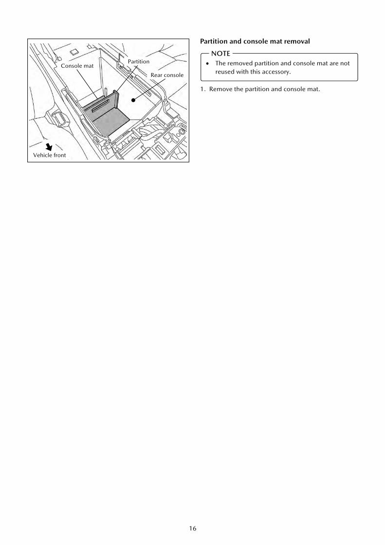
■ Rear console processing
1. Remove the bolts.
2. Make a marking to indicate the hole position in the place shown in the diagram at left.
3. Use the ultrasonic cutter to make a hole in the rear console.
6. PREPARATION FOR INSTALLATION
Place a metal plate or wooden board underneath the rear console to protect the vehicle.
Depending on the vehicle specifications, there may be a rear vent duct underneath the rear console box. Be careful not to damage it.
After drilling the hole, file away any rough edges and burrs until the edges are smooth. After this, remove the metal plate or wooden board which was set in place to protect the vehicle and clean away any shavings, etc.
CAUTION
The diagram shows a 2WD vehicle. Carry out the same removal operations for 4WD vehicles.
35mm 50mm
Set the metal plate or wooden board in place.
Rear console
Vehicle front
20mm
Reference
Rear console
Hole drilling position
Vehicle front
Rear console
Bolts
The removed bolts are reused with this accessory.
Vehicle front
The drilled hole will be used as a service hole when removing the wireless charger. Drill the hole according to the specified width.
NOTE
NOTE
NOTE

18
■ Cutting the Urethane tape (100×30mm) 1. Cut the urethane tapes in half.
■ Wind the cut urethane tape (1/2) (8 pieces) around the harness (red).
Urethane tape (100×30mm)
1/2
1/2
1/2
1/2
1/2
1/2
1/2
1/2
(For winding around harness (red))
(For winding around electro-tap)
800mm 50mm
Urethane tape (1/2) (8 pieces)
Fuse
Harness (Red)
No cut
1/2
1/2
(For securing harness)
(For securing harness (red))
1/2
(For winding around electro-tap)
1/2

19
1. Peel off the backing paper from the double-sided adhesive tape, and attach the tape to the rear
console.
2. Use the bolts (reuse) to secure the wireless charger tray.
7. WIRELESS CHARGER TRAY AND WIRELESS CHARGER UNIT INSTALLATION
The diagram shows a 2WD vehicle. Carry out the same removal operations for 4WD vehicles.
Backside of Wireless charger tray
Double-sided adhesive tape
View A
Place the backside of the wireless charger tray against the front of the vehicle.
Rear console
*
Vehicle front
* The gaps at left and right should be equal. Vehicle front
Bolts (Reuse) : 8.8-12.7 N・m {90-129 kgf・cm, 78-112 in・lbf}
Rear console
Wireless charger tray
Vehicle front
Diagram of view A
NOTE
*

20
3. Connect the harness to the wireless charger unit.
4. Route the harness while passing them through the hooks.
The hooks can easily become damaged, so handle them carefully when passing the harness through.
It will be easier to pass the harness through the hooks if the harness are slackened by one.
When reassembling, be sure to route the harness over the projection to prevent them from becoming clamped.
CAUTION
Harness 6-pin connector (Black)
Backside of wireless charger unit
Harness (Black)
Hook
Hook
Harness (Red)
(2)
(1)
Slide the harness so that they do not have any slackness.
Be sure to route the harness over the projection.
(1)
* The hook at (2) faces in the opposite direction, so pass the harness (red) through first.

21
5. Pass the harness through the working hole in the rear console, and install the wireless charger unit to the
wireless charger tray.
Check that the harness are not clamped, and then finish the installation.
Install so that the harness pass through the notch in the wireless charger tray.
CAUTION
Vehicle front
Wireless charger unit
Harness
Rear console
Wireless charger tray
Working hole
Notch
Push the parts of the wireless charger unit inside the dotted lines in order to engage the tabs of the wireless charger tray.
Gently push the release windows and check that you can feel with your fingertips that it touches something solid.

22
8. INSTALLATION OF THE HARNESS
Connect the wire of the harness (Black) using an electro-tap. After connecting to the vehicle wiring harness using the electro-tap, bind
with urethane tape.
(1)
Electro-tap (Wrap each with urethane tape) 3-pin connector [Gray/Blue]
(View from harness side)
(B)
Approx. 60 mm
Make a cut in the vehicle harness tube.
Vehicle front Harness (Black)
Power outlet connector
Vehicle wiring harness
To (2)

23
Secure the harness to the backside of the console box with the urethane tape (1/2). Secure the fuse to the vehicle wiring harness case with a tie wrap. Fold back the harness (Black) and secure them to the vehicle wiring harness with a tie wrap.
(2)
▲ Tie wraps 2P
Urethane tape (1/2)
Vehicle wiring harness case
Fuse
Fold back the harness (Black)
Urethane tape (1/2)
To (3)
To (3)
2WD
4WD
Fold back the harness (Red)
Fold back the harness (Black)
Fold back the harness (Black)
Fold back the harness (Black)
Vehicle front
Vehicle front
Vehicle wiring harness
Vehicle wiring harness
Vehicle front Vehicle wiring harness case
Fuse
▲ Tie wraps 2P
From (1)
From (1)
Fold back the harness (Red)
Vehicle front

24
(3) Secure the harness (Red) to the vehicle wiring harness using a tie wrap.
Vehicle wiring harness
▲ Tie wrap 1P
Vehicle wiring harness case
Rear console
To (4)
Vehicle wiring harness case
Vehicle front
From (2)
Harness (Red) (Pass through the gap between the rear console and the vehicle wiring harness case.)

25
Vehicle front
Backside of knee airbag
Bracket
Urethane tape (1/2)
Harness (Red)
▲ Tie wrap 1P
Vehicle front
Knee airbag
(4) Secure the harness (Red) to the bracket using tie wrap. Wrap the harness (Red) around the backside of the knee air bag, and secure
it with the cut urethane tape (1/2) (2 pieces).
To (5)
From (3)

26
Vehicle front
BCM control unit
Secure the harness (Red) to the vehicle wiring harness using a tie wrap. Connect the wire of the harness (Red) using an electro-tap. After connecting to the vehicle wiring harness using the electro-tap, bind with
urethane tape (1/2).
(5)
From (4)
Electro-tap (Wrap each with urethane tape (1/2))
32-pin connector J2 [White] (View from harness side)
(R)
Harness (Red)
▲ Tie wrap 1P
Vehicle wiring harness

27
1. Reinstall parts in the reverse order of the installation procedure in【5.VEHICLE PART REMOVAL】. 2. Refer to “Required servicing after disconnecting/connecting negative battery cable” in the vehicle workshop
manual or the owner’s manual to restore the vehicle functions. 3. Perform reinstallation and inspection of the vehicle parts.
■ When removing the wireless charger unit, follow the procedure given below. 1. Use a cloth or brush to apply soapy water.
2. Apply soapy water to the area where wireless
charging unit’s rubber lip and rear console mated.
3. Use your fingers or a rod to push the release windows
in order to disengage the wireless charger unit and
the wireless charger tray.
9. CAUTIONS WHEN RE-INSTALLING
10. WIRELESS CHARGER UNIT REMOVAL
Vehicle front
Vehicle front
Soapy water application area (all the way around)
Rear console
Wireless charger unit
Release windows
Wireless charger unit
Do not use an object with a sharp tip. It may make holes.
CAUTION
28
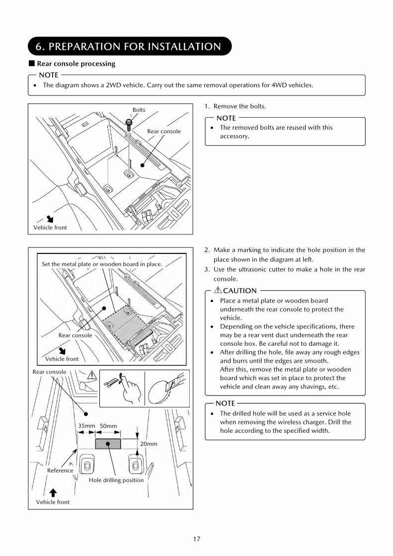
4. Insert tape-wrapped L shape tools (2mm) or a tape-
wrapped wire (2mm) in between the rear console
and the wireless charger unit.
5. Turn the tape-wrapped L shape tools (2mm) or tape-
wrapped wire (2mm) 90° toward the front of the
vehicle.
6. Lift up the tape-wrapped L shape tools (2mm) or
tape-wrapped wire (2mm) to remove the wireless
charger unit.
Vehicle front
17mm
2mm
Tape-wrapped L shape tools (2mm) or tape-wrapped wire (2mm)
Wireless charger unit
Release windows
Rear console
Rubber
Wireless charger unit
Vehicle front
Vehicle front Wireless charger unit
When inserting the tape-wrapped L shape tools (2mm) or tape-wrapped wire (2mm), insert between the rubber surfaces of the release windows.
NOTE * The value given is the
maximum.