Embed Size (px)
Citation preview
Genre Analysis of 2 Research Reports; 3rd
Year
Undergraduate Research Report and a Research Article
and Materials Design
Matthew Ketteringham

Table of Contents
1. Introduction ...................................................................................................................................... 1
1.1 Genre Analysis ........................................................................................................................... 1
1.2 Criteria for Selecting the Articles ............................................................................................... 1
2. Move Analysis of the Discussion Section ........................................................................................ 2
2.1 The Model .................................................................................................................................. 3
2.2 Analysis of the Individual Moves .............................................................................................. 3
2.3 Analysis of the Move Cycle Series ............................................................................................ 5
4. References: ....................................................................................................................................... 7
5. Appendices ..................................................................................................................................... 10
Appendix 1 ..................................................................................................................................... 10
Appendix 2 ..................................................................................................................................... 11
Appendix 3 ..................................................................................................................................... 20
Appendix 4 ..................................................................................................................................... 21
Appendix 5 ..................................................................................................................................... 25
Appendix 6 ..................................................................................................................................... 25
Materials Design ................................................................................................................................ 29
1. Introduction .................................................................................................................................... 29
2. Lesson Plan .................................................................................................................................... 29
3.1 Writing a Research Report: .......................................................................................................... 30
3.2 Lesson 5: Genre Analysis of the Discussion section of a Research Report ................................. 31
4. Rationale ........................................................................................................................................ 33
5. Conclusion ..................................................................................................................................... 34
6. References ...................................................................................................................................... 35
7. Appendices ..................................................................................................................................... 37
Appendix 1 - (Handout 1) The Purpose and Moves Available for the Discussion Section of a
Research Report ............................................................................................................................. 37
Appendix 2 - (Handout 2) Match the Highlighted Moves to the Model ........................................ 38
Appendix 3 – (Handout 3) Highlight the Moves in the Extract ..................................................... 41
Appendix 4 – (Handout 4) Three-part Framework and Move Cycles ........................................... 42
Appendix 5 – (Handout 5) Homework .......................................................................................... 43
1
1. Introduction
1.1 Genre Analysis
Genre analysis has developed from earlier approaches to text analysis since the 1980s to influence
EAP/ESP pedagogies based on the understanding that particular genres have particular
communicative functions. The Research Article (RA) as a genre has been studied extensively as an
example that students are aiming to replicate and become accepted into their chosen Discourse
Community (Martin, 2003). Genre analysis has helped identify a range of different genres across all
disciplines and also highlight differences within the same genre in different disciplines (Dudley-
Evans, 2000; Gardner & Nesi, 2012). However, this trend is not reflected in recent EAP textbooks
due to the discipline 'specific' nature of genre analysis and there is also some criticism that students
should be exposed to more authentic texts that they are more likely to produce in their studies
(Paltridge, 2004). Therefore, the objective of this study is to analyse the discussion section of two
research reports focussing on the move structures to discuss findings and to develop classroom
material to enhance students’ understanding of the moves available in the discussion section.
1.2 Criteria for Selecting the Articles
The two articles chosen to analyse were selected using six criteria; Genre, Discipline, Length,
Quality, Level, and Native Writer (NW). First, the Research Report Genre was selected as the
published research article is the main medium for advancing scientific knowledge (Holmes, 1997).
Next, the Discussion section was chosen as the communicative moves of the Abstract (see
Anderson & Maclean, 1997; Martin, 2003), Introduction (see Swales, 1981 cited in Holmes, 1997;
Swales, 1990; Samraj, 2002) and Results (see Brett, 1994; Williams 1999) sections have previously
received considerable attention. Also, the Discussion section is claimed to be the most difficult for
students to write because it requires students to explain, evaluate and make generalisations, moving
away from description, about what they have seen (Dudley-Evans, 1994; Martin, 2003; Peacock,
2
2002). Engineering was chosen as the discipline area because it is the most relevant to my current
teaching situation. I teach EAP to Foundation Level Maths and Physics students, preparing them to
enter the School of Engineering. The article lengths were selected between 3000-7000 words to
represent the average length of articles submitted for publication. The student work on both the
British Academic Written English (BAWE) Corpus and the Michigan Corpus of Upper Level
Student Papers (MICUSP) were selected due to their proficiency in their chosen field scoring a
'Distinction' or 'A' grade and the chosen RA has an Impact Factor Score of 5.106. An Undergraduate
Research Report (URR) and a published RA were chosen to help students identify the required
moves appropriate to present findings in the Engineering discipline and to highlight differences
between students tentatively making claims as apprentices vying for acceptance, against researchers
already accepted within their academic community (Widdowson, 1998). Finally, a criterion for both
papers was Native Speaker (NS) writer. The URR is by a NS writer; however, after initial research
for the RA it became evident that it would be difficult to distinguish this through names and
institutions alone and also there seemed to be a lack of published material by NS writers in the same
sphere as the chosen URR (Vehicle Exhaust Heat Recover with Thermoelectric Generators).
Although this criterion was not entirely met, it should not significantly impact the analysis as all
other criteria were met.
2. Move Analysis of the Discussion Section The first step in analysing the two texts will look at the 'rhetorical movement' described by Swales
(1990:140) as 'moves' and defined by Holmes (1997:325) as a 'segment of text that is shaped and
constrained by a particular communicative function'. The communicative purpose of the discussion
section is to present findings and arguments based on the author's research (Parkinson, 2011). The
Discussion section of the Introduction, Methods, Results, Discussion (IMRD) research report model
is perhaps the most difficult to analyse due to its inconsistency in length and also the possible
convergence of both the Results, and the Discussion section (Swales, 1990).
3
2.1 The Model
The model used to analyse the two discussion sections is Peacock's (2002) 8 move cycle series
which is a revised version based on Dudley-Evans's (1994) model that takes into consideration
disciplinary differences and Native/Non-Native Writer differences (See Appendix 1:10).
2.2 Analysis of the Individual Moves
Peacock (2002) suggests that researchers classify the moves working from sentence level analysis
and by assigning all sentences to a move.
Text 1: The Undergraduate Research Report (URR)
Thermoelectric Waste Heat Recovery for a Toyota Prius (MICUSP, 2009; full text see Appendix 2:
11)
Table 1 (See Appendix 3:20) shows the move used in each sentence. All eight moves are evident in
the URR. The frequency of the moves will be discussed below.
Text 2: The Research Article
Experiments and simulations on low-temperature waste heat harvesting system by thermoelectric
power generators. (Hsu et al., 2011; full text see Appendix 4:21)
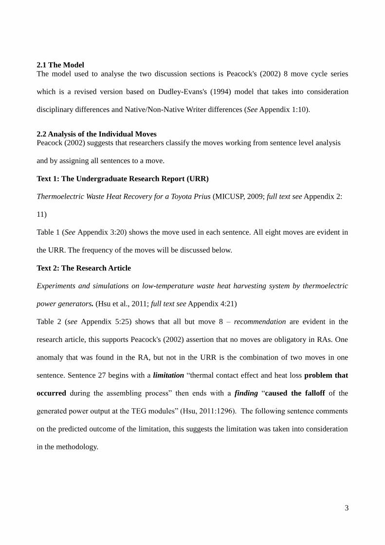
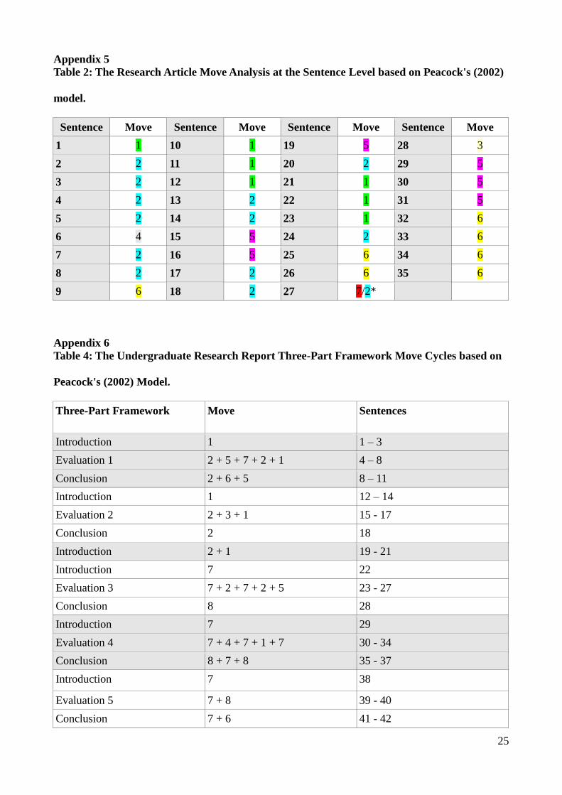
Table 2 (see Appendix 5:25) shows that all but move 8 – recommendation are evident in the
research article, this supports Peacock's (2002) assertion that no moves are obligatory in RAs. One
anomaly that was found in the RA, but not in the URR is the combination of two moves in one
sentence. Sentence 27 begins with a limitation “thermal contact effect and heat loss problem that
occurred during the assembling process” then ends with a finding “caused the falloff of the
generated power output at the TEG modules” (Hsu, 2011:1296). The following sentence comments
on the predicted outcome of the limitation, this suggests the limitation was taken into consideration
in the methodology.
4
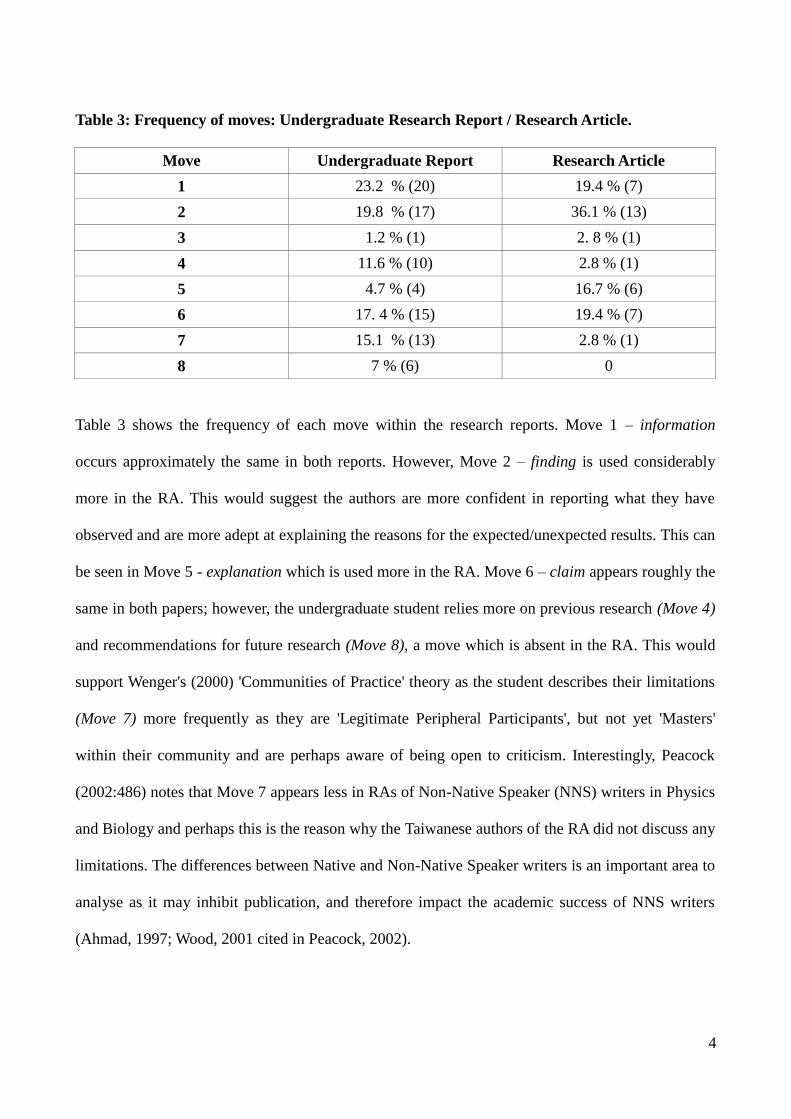
Table 3: Frequency of moves: Undergraduate Research Report / Research Article.
Move Undergraduate Report Research Article
1 23.2 % (20) 19.4 % (7)
2 19.8 % (17) 36.1 % (13)
3 1.2 % (1) 2. 8 % (1)
4 11.6 % (10) 2.8 % (1)
5 4.7 % (4) 16.7 % (6)
6 17. 4 % (15) 19.4 % (7)
7 15.1 % (13) 2.8 % (1)
8 7 % (6) 0
Table 3 shows the frequency of each move within the research reports. Move 1 – information
occurs approximately the same in both reports. However, Move 2 – finding is used considerably
more in the RA. This would suggest the authors are more confident in reporting what they have
observed and are more adept at explaining the reasons for the expected/unexpected results. This can
be seen in Move 5 - explanation which is used more in the RA. Move 6 – claim appears roughly the
same in both papers; however, the undergraduate student relies more on previous research (Move 4)
and recommendations for future research (Move 8), a move which is absent in the RA. This would
support Wenger's (2000) 'Communities of Practice' theory as the student describes their limitations
(Move 7) more frequently as they are 'Legitimate Peripheral Participants', but not yet 'Masters'
within their community and are perhaps aware of being open to criticism. Interestingly, Peacock
(2002:486) notes that Move 7 appears less in RAs of Non-Native Speaker (NNS) writers in Physics
and Biology and perhaps this is the reason why the Taiwanese authors of the RA did not discuss any
limitations. The differences between Native and Non-Native Speaker writers is an important area to
analyse as it may inhibit publication, and therefore impact the academic success of NNS writers
(Ahmad, 1997; Wood, 2001 cited in Peacock, 2002).

5
2.3 Analysis of the Move Cycle Series
The moves outlined above are combined with two or more moves to create a three-part framework
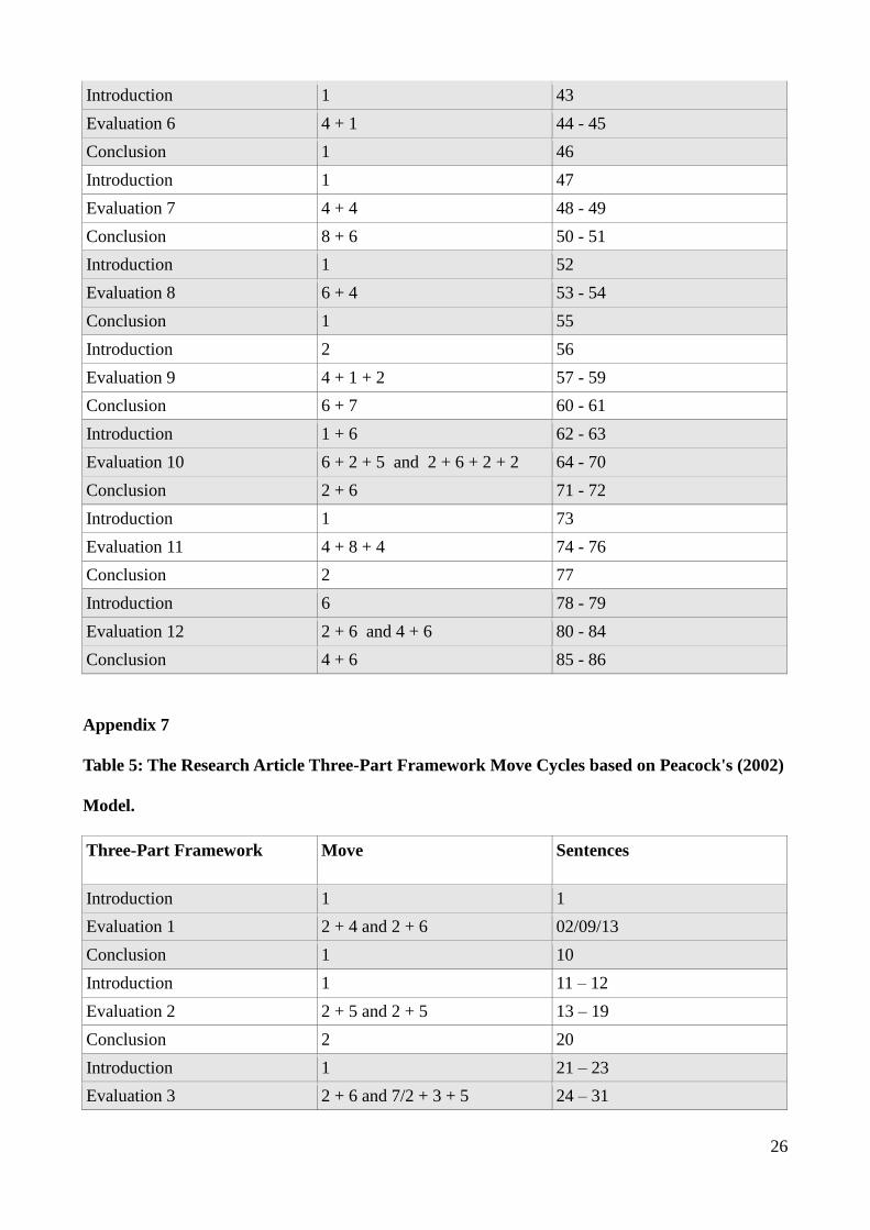
(Introduction-Evaluation-Conclusion) and run in cycles (Dudley-Evans, 1994). Table 4 & 5 (see
Appendix 6 & 7:25/26) show the RA went through 3 distinct move cycles compared to the URR
which went through 12 cycles in total. Peacock's (2002) analysis suggested the average move cycle
per RA was 2.2. The student report is longer than the RA discussion section which could be a factor
in the large number of cycles. In all cases, bar Evaluation 3 & 4 in the URR, all the Introductions
followed the three-part framework beginning with move 1, 2 or 6. The Evaluation of the URR uses
moves 2 + 6, 6 +4 and 4 +6 (21%), but mostly it does not follow the most common cycles from the
model and consists of a variety of move combinations, often with 2 or more. The RA Evaluation
mostly follows the model and uses moves 2 + 4, 2 + 6, and 3 + 4 (50%). Finally, the model is
accurate three times (25%) in the URR Conclusions (2 + 6, 8 +6 and 7 +6), but it is not represented
in the RA. A single move for the Conclusion is used 53 % of the time across both reports instead of
the two moves suggested in the model. As previously mentioned no moves are obligatory; however,
move 1 – information, move 2- findings, and move 6- claim were found in 87 %, 73 %, and 60 % of
move cycles. Move 1- information begins a move cycles 67 % of the time and could be considered
what Hopkins and Dudley-Evans (1988:117) call a “posthead” move. A posthead move is used to
present background information before a finding (Move 2). Overall, the RA follows the model
closer than the URR; however, the URR uses all the moves and some common cycle combinations
which indicate the use of the model could be an important tool in discipline specific EAP/ESP
materials design.
3. Conclusion
Genre analysis is a useful pedagogical tool to help prepare students for the academic contexts they
plan to enter. The analysis above demonstrates that genre analysis can identify the moves available

6
to students for a particular genre, or section of a genre, and can help students understand
disciplinary differences. Models can be used to show the rhetorical patterns used in academic
discourse, but as evidenced above, a model is a comprehensive guide not a prescriptive tool that
must be followed. By offering students all the available patterns they are given the opportunity to
make their own choices and create their own meaning. One possible criticism of move analysis is
the subjectivity involved in move classification and the lack of uniform agreement. However, based
on the analysis above EAP practitioners have access to reliable models to create useful pedagogical
tools.
7
4. References: Anderson, K. & Mclean, J. (1997) A genre analysis study of 80 medical abstracts. Edinburgh
Working Papers in Applied Linguistics, 8, 1-23.
Brett, P. (1994) A genre analysis of the results section of sociology articles. English for Specific
Purposes, 13, 47-59.
Dudley-Evans, T. (1994) Genre analysis an approach to text analysis for ESP. In: Coulthard, M.
(Ed.), Advances in Written Text Analysis. Routledge: London, 219 – 228.
Dudley-Evans, T. (2000) Genre analysis: a key to a theory of ESP? Ibérica: Revista de la
Asociación Europea de Lenguas para Fines Específicos (AELFE), 2, 3-11.
Gardner, S. & Nesi, H. (2012) A Classification of Genre Families in University Student Writing.
Applied Linguistics, 34 (1), 1-29.
Holmes, R. (1997) Genre Analysis, and the Social Sciences: An Investigation of the Structure of
Research Article Discussion Sections in Three Disciplines. English for Specific Purposes, 16 (4),
321-337.
Hopkins, A. & Dudley-Evans, T. (1988) A Genre-based Investigation of the Discussion Sections in
Articles and Dissertations. English for Specific Purposes, 7, 113 – 121.
Hsu, Cheng-Ting., Huang, Gia-Yeh., Chu, Hsu-Chen., Yu, Ben., & Yao, Da-Jeng. (2011)
Experiments and simulations on low-temperature waste heat harvesting system by thermoelectric
power generators. Applied Energy, 88, 1291-1297.
Martin, Pedro. Martin. (2003) A genre analysis of English and Spanish research paper abstracts in

8
experimental social sciences. English for Specific Purposes, 22 (1), 25-43.
Michigan Corpus of Upper-level Student Papers. (2009). Ann Arbor, MI: The Regents of the
University of Michigan. Thermoelectric Waste Heat Recovery for a Toyota Prius, accessed April
15th
2013, <http://search-micusp.elicorpora.info/search/view/?pid=MEC.G0.04.1>.
Paltridge, B. (2004) Academic Writing. Language Teaching, 37, 87-105.
Parkinson, J. (2011) The discussion section as argument: The language used to present knowledge
claims. English for Specific Purposes, 30, 164 – 175.
Peacock, Matthew. (2002) Communicative moves in the discussion section of research articles.
System, 30, 479-497.
Samraj, B. (2002) Introductions in research articles: variations across disciplines. English for
Specific Purposes, 21, 1-17.
Swales, John, M. (1990) Genre Analysis: English in academic and research settings. 13th
Printing
2008. Cambridge: Cambridge University Press.
Widdowson, H.G. (1998) Communication and Community: The pragmatics of ESP. English for
Specific Purposes, 17 (1), 3-14.
Williams, I.A. ( 1999) Results section of medical research articles: analysis of rhetorical categories
for pedagogical purposes. English for Specific Purposes, 18 (4), 347-366.

9
Wenger, E. (2000) Communities of Practice and Social Learning Systems. Organization, 7(2),225-
246.

10
5. Appendices
Appendix 1
Discussion sections have a three-part framework involving a series of move cycles
combining two or more of these eight moves:
1. information move (background about theory/research aims/methodology)
2. finding (with or without a reference to a graph or table)
3. expected or unexpected outcome (comment on whether the result is expected or
not)
4. reference to previous research
5. explanation (reasons for expected or unexpected results)
6. claim [contribution to research (sometimes with recommendations for action)]
7. limitation
8. recommendation (suggestions for future research)
The three-part framework and move cycle series are:
I. Introduction (Moves 1, or 2, or 6)
II. Evaluation (the key move cycles are 2 + 4, 2 + 6, 3 + 4, and 3 + 5. Other less
common cycles are 6 + 4 and 4 + 6)
III. Conclusion (moves 2 + 6, or 8, or 8 + 6, or 7 + 6).
(Peacock, 2002: 492)

11
Appendix 2
Discussion
Sentence 1 In order to draw conclusions about our data, we needed to assess the validity
Paragraph 1 and implications of our results.
2 We then also further investigated the characteristics of the Toyota Prius, and current
and future TEG technologies.
Paragraph 2 CHOICE OF OPTIMUM HEAT SINK We chose to base the extrapolation of our
laboratory data to driving conditions using the best heat sink tested in the
laboratory.
4 We attempted to use an ANOVA to determine this heat sink, but the
analysis only found one significant factor (pin length) using a 90% confidence
interval.
5 This may have been due to inaccurate laboratory tests (see below).
6 In addition, the ANOVA did not take into account important design considerations
such as cost, size, and weight.
7 In the initial laboratory tests, the S153020W heat sink produced the highest power
output per cost, and was one of the smallest and lightest heat sinks available (see
Table 5, p.11 and Table A.1, Appendix A).
8 Thus, we chose to extrapolate assuming the use of S153020W heat sinks.
Paragraph 3 While a small fan mounted on top of the heat sink may have increased the
convective heat transfer from the heat sink, we chose not to propose the use of a fan
for several reasons.
10 The fans would take power from the system, add weight to the car, and add a degree
of complexity to the system due to moving parts.

12
11 Since the fans were only able to generate a maximum of about 3 m/s (6.7mph)
while using about 1 watt of power, the increased convection due to the fan would
not outweigh the energy cost of using the fan.
Paragraph 4 DETERMINATION OF LUMPED THERMAL CONDUCTIVITY To
determine the lumped thermal conductivity (K) of the TEG, we performed a
laboratory test with no heat sink.
13 In this test, the fan was blowing over the TEG.
14 In the tests using heat sinks, we used the heat sink to shield the thermocouple from
the airflow so that convection from the thermocouple tip did not alter our
temperature measurements.
15 However, when there was no heat sink, there was nothing to protect the
thermocouple tip from the fan, and the temperature reading was lower than the
actual temperature.
16 Using the K value determined from this test predicted that the heat sink surface was
hotter than the cold side of the TEG, which cannot be true, since heat always flows
from high to low temperatures.
17 Thus, we were given consent to use one set of data from another ME495 group (see
Acknowledgements Section) in which the hot and cold side temperatures were
measured without a heat sink and with no airflow over the TEG.
18 The new K value determined from this data yields more realistic predictions of
TEG temperatures.
19 DETERMINATION OF CONVECTION HEAT TRANSFER COEFFICIENT
Paragraph 5 Figure 8, p.12 shows that there is a linear relationship between convection heat
transfer coefficient (hA) of the S153020W heat sink and fan speed over the range of

13
air speeds tested.
20 For the purposes of extrapolation, we assumed that this trend continues for higher
air velocities, even though our air velocity range is limited.
21 In addition, we assumed that hA is independent of temperature.
22 PROBLEMS WITH EXPERIMENTAL SETUP There were many problems with
Paragraph 6 the small scale laboratory set up used to determine the optimal heat sink for this
application and extrapolate data to driving conditions.
23 First, the hotplate had a very uneven temperature distribution.
Paragraph 7 If the thermocouple used to measure the hotplate temperature was moved even
slightly, the temperature reading would change by up to 20°C.
25 In addition, the set point of the hotplate was not consistent.
26 Setting the hotplate to 260°C resulted in hotplate temperatures of
between 150°C and 210°C, varying from test to test.
27 While we attempted to compensate for these problems by changing the set point to
achieve a consistent temperature, and trying to place the thermocouple in a
consistent spot, the temporal and spatial fluctuations made the hotplate temperature
extremely difficult to measure accurately.
28 A more precise heating element would have greatly improved our temperature
reading accuracy, and thus improve our performance predictions.
Paragraph 8 Second, the contact resistance of the set-up did not seem to be consistent.
30 While we tried to use a consistent amount of thermal grease at each contact, other
factors may have affected this resistance.
31 For example, contact resistance decreases with increasing contact pressure

14
(SOURCE).
32 However, we used heat sinks of different weights, so the contact pressure was never
consistent.
33 Additionally, to measure the heat sink surface temperature, we had to put some
pressure on the heat sink with the thermocouple.
34 While we attempted to keep this pressure consistent, we had to hold
the thermocouple by hand, and the pressure may have changed from test to test.
35 Our results would be more accurate if the contact pressure could be kept constant
by using a clamp to hold down the heat sink and take temperature measurements. 36
Additionally, the thermal grease seemed to clump over time and create air pockets
that would increase the contact resistance.
37 This could be remedied by using a different kind of thermal grease or by reapplying
thermal grease between each test.
Paragraph 9 Finally, the resistor used to simulate a load across the TEG was attached very close
to the TEG, so the resistor heated up during the tests.
39 This temperature change may have changed the resistance, which would affect our
voltage measurements.
40 If the resistor had been placed in parallel with the TEG with longer wires, the
resistor could have been kept closer to the ambient temperature, and thus
maintained a more consistent resistance.
Paragraph 10 These laboratory testing problems probably affected our results for our ANOVA
analysis and our extrapolation to real world driving conditions.
42 However, since the results of our system analysis show that the necessary TEG

15
technology is an order of magnitude higher than that which is available today, our
recommendations are not highly affected by our laboratory problems.
Paragraph 11 CHARACTERISTICS OF THE TOYOTA PRIUS The Prius produces less
exhaust than traditional cars because of its hybrid engine.
44 Figure 10, p.16 shows that the Prius’ engine will only produce exhaust gas when the
car is cruising, since this is the only time that the engine is running on gasoline
(SOURCE).
45 Thus, the frequent engine shutoffs during starting and stopping cause the Prius’
exhaust temperature during city driving is lower than that of a traditional small car.
46 This has been incorporated in our estimate of the exhaust temperature.
FIGURE HERE:
Figure 10: Diagram of the Prius' energy use profile over time. (SOURCE)
47 The Prius also uses fuel saving technology other than the hybrid engine.
48 The Prius’ fuel efficiency is increased by the car’s aerodynamic shape, which is due
in part to its flat underside designed at for smoother air flow beneath the car (see
Fig. 11, below).
49 The Prius also uses a weight saving design, using lightweight components
as much as possible (SOURCE).
50 Any proposed changes to the Prius design should be made with these factors in
mind.
51 In our aircooled system the TEGs and heat sinks would add both weight and drag
beneath the car.
FIGURE HERE:
Figure 11: The underside of the Prius is flat to make the under body air flow smoother and reduce
drag. (SOURCE)

16
Paragraph 13 CURRENT TEG TECHNOLOGIES Research was done on the previously
completed work related to thermoelectric generators in an automotive application.
53 It was found that two current TEG types were most appropriate for the Toyota Prius
exhaust temperatures and are compared in the Table 8, p.17.
54 Other TEG materials and their respective ZT values at various temperatures are
shown in Fig. 4, p.8.
55 These materials have lower ZT values than the materials listed in Table 8, so they
were not considered for this application.
TABLE HERE:
Table 8: Comparison of characteristics for recommended TEG Materials.
Paragraph 14 EXTRAPOLATED PERFORMANCE PREDICTIONS ANALYSIS Table 7, p.
shows that while the system discussed in the Results Section can produce a
significant amount of power, the net savings of the system makes its
implementation completely impractical.
57 The goal of several US Department of Energy programs investigating waste heat
recovery is a fuel economy increase of 10% (SOURCE).
58 In the Prius, this corresponds to a fuel economy increase of 4.6 mpg.
59 Neglecting the TEG system weight, Eq. 8, p.8 implies that this could be achieved
with a TEG power generation of 1150 W.
60 In order for this to be possible with the system proposed in the Results Section
above, our models show that TEGs with a ZT near 3 would need to be developed. 61
However, the cost of the system would still be a major hurdle before
implementation could be realistic.
62 In order to estimate the requirements for a TEG system to be feasible on the Toyota
Paragraph 15 Prius, an economic evaluation was performed to determine the point at which a
17
TEG system could pay for itself over the lifetime of the car (the break-even point).
63 One way to reduce cost would be to reduce the number of TEGs needed.
64 By only mounting TEGs on the three highest temperature elements (the exhaust
manifold, exhaust pipe, and catalyst), the number of TEGs could be reduced to 155.
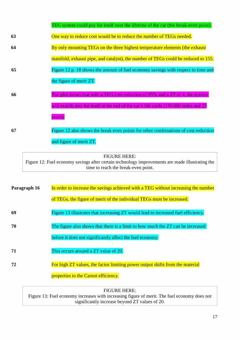
65 Figure 12 p. 18 shows the amount of fuel economy savings with respect to time and
the figure of merit ZT.
66 The plot shows that with a TEG cost reduction of 85% and a ZT of 4, the system
will exactly pay for itself at the end of the car’s life cycle (150,000 miles and 25
years).
67 Figure 12 also shows the break even points for other combinations of cost reduction
and figure of merit ZT.
FIGURE HERE:
Figure 12: Fuel economy savings after certain technology improvements are made illustrating the
time to reach the break-even point.
Paragraph 16 In order to increase the savings achieved with a TEG without increasing the number
of TEGs, the figure of merit of the individual TEGs must be increased.
69 Figure 13 illustrates that increasing ZT would lead to increased fuel efficiency.
70 The figure also shows that there is a limit to how much the ZT can be increased
before it does not significantly affect the fuel economy.
71 This occurs around a ZT value of 20.
72 For high ZT values, the factor limiting power output shifts from the material
properties to the Carnot efficiency.
FIGURE HERE:
Figure 13: Fuel economy increases with increasing figure of merit. The fuel economy does not
significantly increase beyond ZT values of 20.

18
73 FUTURE TEG TECHNOLOGIES New TEG materials being developed will
have significantly higher efficiencies and lower costs than current materials.
74 Quantum well TEGs currently being developed are especially lucrative, since they
have raw material costs more than 10 times less than that of the Bi2Te3 TEGs.
75 Development of technology for automated fabrication should further decrease the
cost of quantum well TEGs.
76 In addition, quantum well TEGs are predicted to have very high efficiencies
compared to the TEGs available today and can also be utilized in higher
temperature ranges (SOURCE).
77 Figure 14 shows the relationship between efficiency and cost of future TEG
modules with respect to temperature.
FIGURE HERE:
Figure 14: New Quantum Well TEG technologies predict a substantial future increase in efficiency
and a decrease in price per watt (SOURCE)
Paragraph 18 OTHER WAYS TO ACHIEVE A PERFORMANCE IMPROVEMENT There
are other ways to improve the power output of a TEG waste heat recovery system
besides advancement of TEG materials.
79 Use of these techniques could make a practical TEG waste heat recovery system
more achievable.
Paragraph 19 The temperature of the gas that flows through the exhaust system is higher than the
temperature on the outer shell of the exhaust system.
81 Since the TEG is mounted on this outer shell, maximizing this temperature would
increase the TEG power output.

19
82 To achieve this, the exhaust system could be constructed with a less thermally
resistive material, or the exhaust gas could be forced to have turbulent flow with the
help of spiralled fins inside the exhaust system (SOURCE).
Paragraph 20 In addition, a reduction in thermal resistance of the insulating wafer that is placed
between the exhaust system and the TEG and also between the TEG and heat sink
could also improve the performance (SOURCE).
84 Similarly, an increased thermal conductivity of the thermal paste would increase
heat flux through the TEG system and thus improve performance.
Paragraph 21 Many studies of waste heat recovery systems in automobiles have used coolant
from the car’s engine to cool the cold side of the TEG instead of flowing ambient
air (SOURCE X 4).
86 Use of such a coolant system would increase the temperature difference across the
TEG and thus increase our power output.

20
Appendix 3
Table 1: The Undergraduate Research Report Move Analysis at the Sentence Level based on
Peacock's (2002) model.
Sentence Move Sentence Move Sentence Move Sentence Move
1 1 22 7 43 1 64 6
2 1 23 7 44 4 65 2
3 1 24 2 45 1 66 5
4 2 25 7 46 1 67 2
5 5 26 2 47 1 68 6
6 7 27 5 48 4 69 2
7 2 28 8 49 4 70 2
8 1 29 7 50 8 71 2
9 2 30 7 51 6 72 6
10 6 31 4 52 1 73 1
11 5 32 7 53 6 74 4
12 1 33 1 54 4 75 8
13 1 34 7 55 1 76 4
14 1 35 8 56 2 77 2
15 2 36 7 57 4 78 6
16 3 37 8 58 1 79 6
17 1 38 7 59 2 80 2
18 2 39 7 60 6 81 6
19 2 40 8 61 7 82 4
20 1 41 7 62 1 83 6
21 1 42 6 63 6 84 6
85 4
86 6
21
Appendix 4
4.4 Discussion
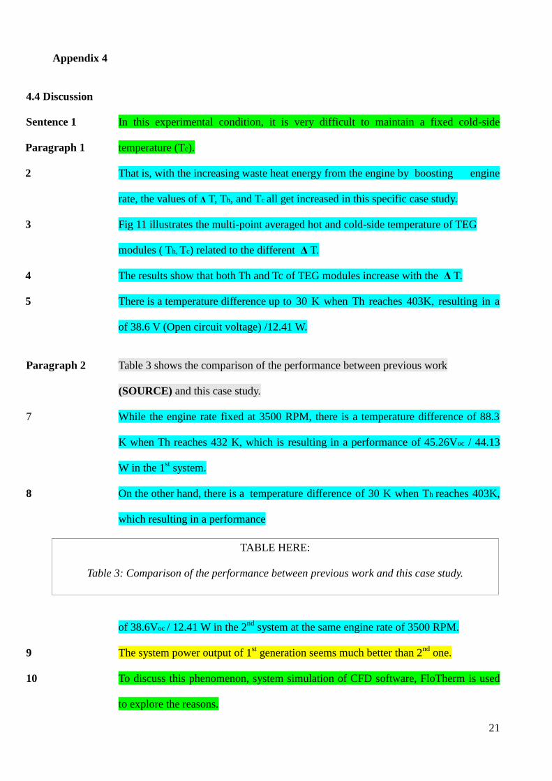
Sentence 1 In this experimental condition, it is very difficult to maintain a fixed cold-side
Paragraph 1 temperature (Tc).
2 That is, with the increasing waste heat energy from the engine by boosting engine
rate, the values of Δ T, Th, and Tc all get increased in this specific case study.
3 Fig 11 illustrates the multi-point averaged hot and cold-side temperature of TEG
modules ( Th, Tc) related to the different Δ T.
4 The results show that both Th and Tc of TEG modules increase with the Δ T.
5 There is a temperature difference up to 30 K when Th reaches 403K, resulting in a
of 38.6 V (Open circuit voltage) /12.41 W.
Paragraph 2 Table 3 shows the comparison of the performance between previous work
(SOURCE) and this case study.
7 While the engine rate fixed at 3500 RPM, there is a temperature difference of 88.3
K when Th reaches 432 K, which is resulting in a performance of 45.26Voc / 44.13
W in the 1st system.
8 On the other hand, there is a temperature difference of 30 K when Th reaches 403K,
which resulting in a performance
TABLE HERE:
Table 3: Comparison of the performance between previous work and this case study.
of 38.6Voc / 12.41 W in the 2nd
system at the same engine rate of 3500 RPM.
9 The system power output of 1st generation seems much better than 2
nd one.
10 To discuss this phenomenon, system simulation of CFD software, FloTherm is used
to explore the reasons.
22
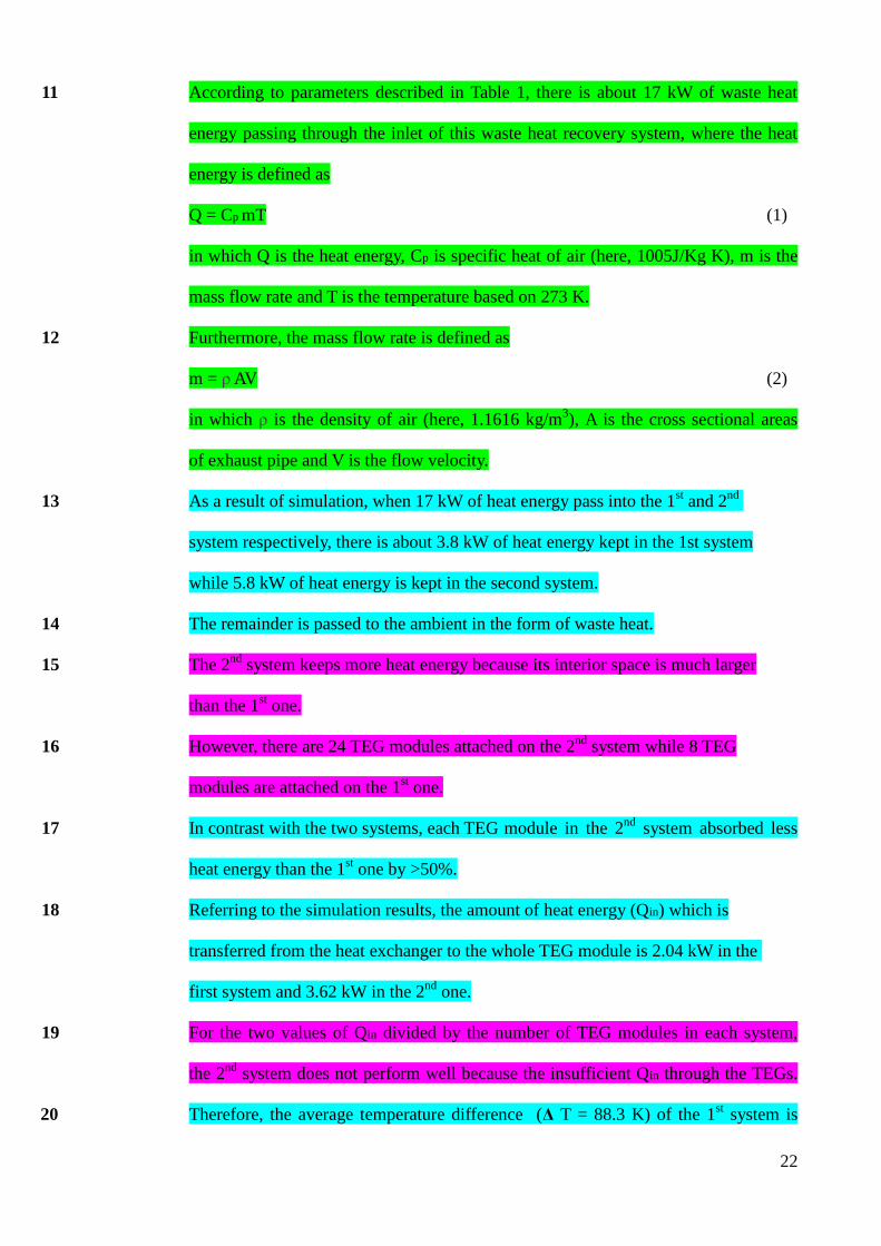
11 According to parameters described in Table 1, there is about 17 kW of waste heat
energy passing through the inlet of this waste heat recovery system, where the heat
energy is defined as
Q = Cp mT (1)
in which Q is the heat energy, Cp is specific heat of air (here, 1005J/Kg K), m is the
mass flow rate and T is the temperature based on 273 K.
12 Furthermore, the mass flow rate is defined as
m = ρ AV (2)
in which ρ is the density of air (here, 1.1616 kg/m3), A is the cross sectional areas
of exhaust pipe and V is the flow velocity.
13 As a result of simulation, when 17 kW of heat energy pass into the 1st and 2
nd
system respectively, there is about 3.8 kW of heat energy kept in the 1st system
while 5.8 kW of heat energy is kept in the second system.
14 The remainder is passed to the ambient in the form of waste heat.
15 The 2nd
system keeps more heat energy because its interior space is much larger
than the 1st one.
16 However, there are 24 TEG modules attached on the 2nd
system while 8 TEG
modules are attached on the 1st one.
17 In contrast with the two systems, each TEG module in the 2nd
system absorbed less
heat energy than the 1st one by >50%.
18 Referring to the simulation results, the amount of heat energy (Qin) which is
transferred from the heat exchanger to the whole TEG module is 2.04 kW in the
first system and 3.62 kW in the 2nd
one.
19 For the two values of Qin divided by the number of TEG modules in each system,
the 2nd
system does not perform well because the insufficient Qin through the TEGs.
20 Therefore, the average temperature difference (Δ T = 88.3 K) of the 1st system is

23
much larger than that of the 2nd
one ( Δ T = 30 K) when the same input heat energy
(~ 17 kW) is applied.
Paragraph 3 Referring to Fig.9, the generated open circuit voltgae (Voc), with 24 TEG modules
as a linear function of the temperature difference between their hot and cold side
( Δ T), can be fitted by
Voc = 1.21451 Δ T (3)
and the generated maximum power (Pmax) with 24 TEG modules as a second-
ordered function of Δ T can be fitted by
Pmax = 0.00934 Δ T2 + 0.13377 Δ T (4)
Paragraph 4 In order to modify this system, the fitting lines of Eqs. (3) and (4) are investigated
in Figs. 9 and 10 respectively.
23 R-square represents the explanation ability of a regression model.
24 The values of R square in Figs. 9 and 10 are 0.99692 and 0.99625 respectively
which imply the accuracy of the fitting lines that explain our measurement results
are more than 99%.
25 On the basis of the above discussion, increasing waste heat temperature is
advantageous to promote system performance.
26 A notably analysis result can be obtained that there would be 131.45 Voc/ 106.77 W
with an appropriate heat source which can boost the Δ T up to 100 K according to
Eqs. (3) and (4).
Paragraph 5 Moreover, thermal contact effect and heat loss problem that occurred during the
assembling process caused the falloff of the generated power output at the TEG
modules.

24
28 The values of the falloff are about 20.5 % between the predicted curve and
measured result at Δ T = 30 K, as shown in Fig. 10.
29 At low temperatures, there is relatively good agreement between the predicted
performance and the measurements.
30 However, the deviation of the prediction extends largely with increasing Δ T as Δ T
> 25 K (or Th > 388 K).
31 In addition to thermal contact effect and heat loss problem, this specific deviation
as Δ T > 25 K (or Th >388 K might) be caused by uneven thermal field distribution
as described in Fig. 3.
32 When waste heat temperature increased by boosting engine rate, the phenomenon of
uneven thermal field distribution dominates which leads to uneven Δ T between
TEG modules.
33 One TEG module out of the system with unexpectedly smaller Δ T will influence
the overall performance of the entire TEG network since these TEG modules are all
connected in series electrically.
34 Thence the uneven thermal field distribution that causes the deviation between the
predictions and measurements extends largely with increasing Δ T (or Th) is
assumed in this case.
35 Supplement with the predicted curves in Figs. 9 and 10 they are proportional to
expand 24 times of the results in Fig. 5A and b.
25
Appendix 5
Table 2: The Research Article Move Analysis at the Sentence Level based on Peacock's (2002)
model.
Sentence Move Sentence Move Sentence Move Sentence Move
1 1 10 1 19 5 28 3
2 2 11 1 20 2 29 5
3 2 12 1 21 1 30 5
4 2 13 2 22 1 31 5
5 2 14 2 23 1 32 6
6 4 15 5 24 2 33 6
7 2 16 5 25 6 34 6
8 2 17 2 26 6 35 6
9 6 18 2 27 7/2*
Appendix 6
Table 4: The Undergraduate Research Report Three-Part Framework Move Cycles based on
Peacock's (2002) Model.
Three-Part Framework Move Sentences
Introduction 1 1 – 3
Evaluation 1 2 + 5 + 7 + 2 + 1 4 – 8
Conclusion 2 + 6 + 5 8 – 11
Introduction 1 12 – 14
Evaluation 2 2 + 3 + 1 15 - 17
Conclusion 2 18
Introduction 2 + 1 19 - 21
Introduction 7 22
Evaluation 3 7 + 2 + 7 + 2 + 5 23 - 27
Conclusion 8 28
Introduction 7 29
Evaluation 4 7 + 4 + 7 + 1 + 7 30 - 34
Conclusion 8 + 7 + 8 35 - 37
Introduction 7 38
Evaluation 5 7 + 8 39 - 40
Conclusion 7 + 6 41 - 42
26
Introduction 1 43
Evaluation 6 4 + 1 44 - 45
Conclusion 1 46
Introduction 1 47
Evaluation 7 4 + 4 48 - 49
Conclusion 8 + 6 50 - 51
Introduction 1 52
Evaluation 8 6 + 4 53 - 54
Conclusion 1 55
Introduction 2 56
Evaluation 9 4 + 1 + 2 57 - 59
Conclusion 6 + 7 60 - 61
Introduction 1 + 6 62 - 63
Evaluation 10 6 + 2 + 5 and 2 + 6 + 2 + 2 64 - 70
Conclusion 2 + 6 71 - 72
Introduction 1 73
Evaluation 11 4 + 8 + 4 74 - 76
Conclusion 2 77
Introduction 6 78 - 79
Evaluation 12 2 + 6 and 4 + 6 80 - 84
Conclusion 4 + 6 85 - 86
Appendix 7
Table 5: The Research Article Three-Part Framework Move Cycles based on Peacock's (2002)
Model.
Three-Part Framework Move Sentences
Introduction 1 1
Evaluation 1 2 + 4 and 2 + 6 02/09/13
Conclusion 1 10
Introduction 1 11 – 12
Evaluation 2 2 + 5 and 2 + 5 13 – 19
Conclusion 2 20
Introduction 1 21 – 23
Evaluation 3 2 + 6 and 7/2 + 3 + 5 24 – 31

27
Conclusion 6 32 - 35

28
Materials Design: Writing the Discussion Section of a
Research Report
29
Materials Design
1. Introduction
The teaching of L2 writing has traditionally followed the process approach of Pre-writng – Writing
– Post Writing activities, where students learn from feedback and drafting. Rhetorical structures and
analysed examples of target texts are generally not used to familiarise students with different genres.
The aim of genre pedagogies is to move away from the inductive approach, as the writer as an
individual, and into the social process of how literacies are created in different communities. Genre
pedagogy is based on a Vygostky inspired approach of 'assisted learning' by scaffolding student
learning into a social activity where meaning is created in contexts applicable to each student’s
environment (Hyland, 2003; 2007; Lantolf & Thorne, 2006).
2. Lesson Plan The aim of the lessons are to introduce students to the Research Report as a genre and to expose
them to the moves, organisational structure and language that is appropriate in their discipline.
Swales (1984 cited in Marshall, 1991) reported that his students claimed they became more critical
readers of both published research articles and their own work, after the use of his analysis of
introductions. The outcome of the lessons would not only equip students with the knowledge of
how to write research reports, but also enable them to transfer the analysis to different genres and
give them an understanding of how their scientific community thinks (Marshall, 1991). The lessons
could be used in either a pre-service Foundation or in-service Undergraduate Level course with
students studying in a Science discipline, preferably Physics or Engineering. The proficiency level
is aimed at IELTS 6.0 – 7.0. Ideally, the classes would be run consecutively with a subject class to
provide the platform for the students to demonstrate what they have learnt and write their own
research reports working in small groups.
30
3.1 Writing a Research Report: Lesson 1
• Introduction to the Research Report as a Genre (Purpose, Intended Audience & Structure)
• Broad topic for discussion based on the text analysis: [This theme would run throughout]
Global Warming & Reducing CO2 Emissions (General)
New Technology in the Automotive Industry
Hybrid Vehicles & Heat Recovery (Related to the texts)
• Genre Analysis of the Abstract
Lesson 2
• Genre Analysis of the Introduction
Lesson 3
• Genre Analysis of the Methodology section
Lesson 4
• Genre Analysis of the Results section
Lesson 5
• Genre Analysis of the Discussion (Lesson Materials below)
Lesson 6
• Genre Analysis of the Conclusion
Lesson 7
• Editing, Peer Review, Referencing
Lesson 8
• Feedback (based on explicit criteria and preferably content feedback by a subject specialist
and feedback on the language and structure taught above by an EAP Practitioner)
One possible alteration to the above sequence could be based on the apparent difficulty of each
section rather than the sequence. Swales and Luebs (2002 cited in Hyland, 2007:158) propose a
methods, abstract, results, introductions, and discussion sequence.

31
3.2 Lesson 5: Genre Analysis of the Discussion section of a Research Report Lesson Aims:
a) To discuss the purpose of the discussion section of a Research Report.
b) To look at an example of the discussion section and identify available moves. [The
definition of a move has already been discussed]
c) To look at an example of the discussion section and identify the organisational structure
of the moves.
Activity 1: The Purpose and Moves in the Discussion Section [Handout 1 – See Appendix 1:9]
In previous lessons we have discussed the purpose of each section of a research report up to the
Results section.
a) Discuss with your partner the purpose of the Discussion section.
________________________________________________________________________________
________________________________________________________________________________
________________________________________________________________________________
b) What do you think should be included in the Discussion? What moves do you think it
should include? Try to think of 8 examples.
1) ________________________________ 2) _______________________________
3) ________________________________ 4) _______________________________
5) ________________________________ 6) _______________________________
7) ________________________________ 8) _______________________________
Activity 2: Match the Highlighted Moves to the Model [Handout 2 – See Appendix 2:10]
Over the past 4 classes we have analysed the Abstract, Introduction, Methods and Results section of
the following 3rd year undergraduate Research Report:
Text 1: Thermoelectric Waste Heat Recovery for a Toyota Prius (MICUSP, 2009).
Read the first 8 paragraphs of the report and try to use the model to match the moves used in each
sentence. The sentences have been colour coded to represent a move. All eight moves have been
used at least once.

32
Activity 3: Highlight the Moves in the Extract [Handout 3 – See Appendix 3:14]
Read the next extract that follows on from Activity 2. Can you identify the different moves
highlighted? [Moves 1, 5, 6, 7 & 8 are used]
Move Structure
The moves are often structured in a three-part framework of Introduction, Evaluation and
Conclusion. Common move cycles include (Peacock, 2002:492):
Introduction – Moves: 1, or 2, or 6
Evaluation – Moves: 2 + 5, 2 + 6, 3 + 5, and 3 + 4 and other less frequent cycles 6 + 5, 5 + 6
Conclusion – Moves: 2 + 6/8, or 8 + 6, or 7 +6
Activity 4: Three-part Framework and Move Cycles [Handout 4 – See Appendix 4:15]
Read the highlighted extract of two cycles from the student Research Report and fill in the table
below with the Sentence and/or Move:
Three-part Framework Sentence Move
Introduction 47 [1 Move]
Evaluation 48 - 49 [2 Moves]
Conclusion 50 - 51 [2 Moves]
Introduction [1 Move]
Evaluation [2 Moves]
Conclusion 55 1
Homework [To be used with Handout 5 – See Appendix 5:16]
Read the discussion section of:
Text 2: Experiments and simulations on low-temperature waste heat harvesting system by
thermoelectric power generators (Hsu et al., 2011).
a) Identify the highlighted moves using the model.
b) Identify the move cycles in Text 2. There are 3 move cycles (Introduction-Evaluation-
Conclusion x 3)
c) Are there any differences in the moves used and the structure of the moves between the research
article and the undergraduate research report?
d) How do these cycles relate to other sections of the research report?

33
4. Rationale
The eight lessons may be presented in a logical genre series that mimic the tasks students have to
undertake in their studies. For example, the Research Report lessons may follow on from a similar
analysis of the Laboratory Report genre. This supports the approach that learning to write is “needs
orientated” and where possible it should be situated in the students' target environment (Hyland,
2007:152). The broad topic for discussion, which would continue throughout the course, would be
'Global Warming and Reducing CO2
Emissions' with the focus being on 'New Technologies in the
Automotive Sector including Heat Recover Systems'. This would create a topic for discussion and
also provide what Hyland (2006:94) called “Stimulus”. Flowerdew (2000:374) reported that
“talking around” the topic motivated students and created 'stimulus' for spoken interaction. The
topic can also be used to provide further examples of research articles or possibly other genres for
discussion. This supports Grabe's (2003) assertion that speaking, reading and writing should be
taught together to improve learning.
The lessons would be taught over a two hour period. The first hour would focus on the moves and
organisational structure of each section. The second hour would focus on the language used within
each move and where possible the students would construct their own section of the genre. Due to
the word count limitation the lesson presented above would only focus on the moves and
organisational structure.
The lesson tasks are created around Peacock's (2002) teaching suggestions based on his revised
model and also Feez's (1998 cited in Hyland, 2007:159) “teaching-learning cycle”. Peacock's (2002)
model was altered slightly reversing moves 4 – Reference to Previous Research and moves 5 –
Explanation, to follow a more logical step when presenting findings (finding - expected or
unexpected outcome - explanation see Appendix 1:9). As previously mentioned genre-based writing
instruction follows a social approach to language learning. The students work together to complete

34
tasks based on the notions of “shared and borrowed consciousness” with the students developing a
deeper understanding of the genre by working together, and with a “knowledgeable other”. The
EAP practitioner becomes a more “knowledgeable” teacher through the analysis of texts and the
understanding of their students' needs (Hyland, 2007:158). Scaffolding and modelling are used in
each activity. The models are used to show common moves and organisational structure in the target
genre. These models can be used to scaffold their own writing, in this case the construction of a
discussion section based on research they are doing in their subject class. Throughout “Reference”
materials are used (see Appendix 1:9) referring to research that supports the theoretical knowledge
of genre and language production in different genres, sections and disciplines (Hyland, 2006:95).
The Homework Activity should help raise students’ awareness that the moves and organisational
structure are not prescribed and once students are aware of the rhetorical patterns available to them
they are in a position to manipulate and critically analyse dominant discourse (Hyland, 2007).
Finally, the last question should highlight the importance of linking to other sections in the report,
and that each section should not stand alone (Flowerdew, 2000).
5. Conclusion The overall outcome of the lesson(s) is to familiarise students to the Research Report Genre. The
model used should show students what moves are available and how to organise the moves in their
own writing. Lesson 5 would be a challenging lesson for students; however, this is five classes into
a total of eight, so students will be familiar with the process of how to analyse texts and they will
already have a good understanding of these particular texts after analysing the previous sections.
35
6. References
Flowerdew, L. (2000) Using a genre-based framework to teach organizational structure in academic
writing. ELT Journal, 54(4), 369 – 378.
Grabe, W. (2003) 1 Q Reading and writing relations: Second language perspectives on research and
practice. In: B. Krol, Ed. Exploring the dynamics of second language writing, New York:
Cambridge University Press. Chp 10.
Hsu, Cheng-Ting., Huang, Gia-Yeh., Chu, Hsu-Chen., Yu, Ben., & Yao, Da-Jeng. (2011)
Experiments and simulations on low-temperature waste heat harvesting system by thermoelectric
power generators. Applied Energy, 88, 1291-1297.
Hyland, K. (2003) Genre-based pedagogies: Asocial response to process. Journal of Second
Language Writing, 12, 17-29.
Hyland, K. (2006) English for Academic Purposes: an advanced resource book. Abingdon:
Routledge.
Hyland, K. (2007) Genre pedagogy: Language, literacy and L2 writing instruction. Journal of
Second Language Writing, 16, 148 – 164.
Lantolf, James. P., & Thorne, Steven. L. (2006) Sociocultural Theory and the Genesis of Second
Language Development. Oxford: Oxford University Press.
Marshall, S. (1991) A Genre-Based Approach to the Teaching of Report Writing. English for

36
Specific Purposes, 10, 3-13.
Michigan Corpus of Upper-level Student Papers. (2009). Ann Arbor, MI: The Regents of the
University of Michigan. Thermoelectric Waste Heat Recovery for a Toyota Prius, accessed April
15th
2013, <http://search-micusp.elicorpora.info/search/view/?pid=MEC.G0.04.1>.
Peacock, Matthew. (2002) Communicative moves in the discussion section of research articles.
System, 30, 479-497.

37
7. Appendices
Appendix 1 - (Handout 1) The Purpose and Moves Available for the Discussion Section of a
Research Report
The purpose of the discussion section is to evaluate your results and interpret your findings with
explanations of expected or unexpected outcomes. You may refer to previous research to support
your claims and you may discuss problems or limitations with your research. Finally you may
recommend ways you could improve your results and areas for further research.
The Moves in the Discussion Section
Here is a list of the eight possible moves you can include in your discussion section. The moves are
adapted from research by Peacock (2002).
1) Information move – This move provides the reader with background theory your research
is based on OR the methodology used in the research OR restate the research aims.
2) Finding move – Here you discuss your findings in relation to your aims. You may refer to
graphs, figures or tables to support your findings.
3) Expected or Unexpected Outcome move – Here you can explain if your findings were
expected or not and you may refer back to your introduction/hypothesis.
4) Explanation move – Here you can explain your interpretations of the finding and why the
results were expected or not.
5) Reference to Previous Research move – Here you can relate your research with previous
research. You may comment if your findings agree or disagree with other research.
6) Claim move – If your research disagreed with previous research you may explain how you
have found out something new and contributed to research. Or if your findings agreed with previous
research you may explain how you have added to existing knowledge.
7) Limitation move – Here you may discuss problems with your methodology or research
design.
8) Recommendation move – Here you can recommend action for further research or how you
could improve your results.

38
Appendix 2 - (Handout 2) Match the Highlighted Moves to the Model
Discussion
Sentence 1 In order to draw conclusions about our data, we needed to assess the validity
Paragraph 1 and implications of our results.
2 We then also further investigated the characteristics of the Toyota Prius, and current
and future TEG technologies.
Paragraph 2 CHOICE OF OPTIMUM HEAT SINK We chose to base the extrapolation of our
laboratory data to driving conditions using the best heat sink tested in the
laboratory.
4 We attempted to use an ANOVA to determine this heat sink, but the
analysis only found one significant factor (pin length) using a 90% confidence
interval.
5 This may have been due to inaccurate laboratory tests (see below).
6 In addition, the ANOVA did not take into account important design considerations
such as cost, size, and weight.
7 In the initial laboratory tests, the S153020W heat sink produced the highest power
output per cost, and was one of the smallest and lightest heat sinks available (see
Table 5, p.11 and Table A.1, Appendix A).
8 Thus, we chose to extrapolate assuming the use of S153020W heat sinks.
Paragraph 3 While a small fan mounted on top of the heat sink may have increased the
convective heat transfer from the heat sink, we chose not to propose the use of a fan
for several reasons.
39
10 The fans would take power from the system, add weight to the car, and add a degree
of complexity to the system due to moving parts.
11 Since the fans were only able to generate a maximum of about 3 m/s (6.7mph)
while using about 1 watt of power, the increased convection due to the fan would
not outweigh the energy cost of using the fan.
Paragraph 4 DETERMINATION OF LUMPED THERMAL CONDUCTIVITY To
determine the lumped thermal conductivity (K) of the TEG, we performed a
laboratory test with no heat sink.
13 In this test, the fan was blowing over the TEG.
14 In the tests using heat sinks, we used the heat sink to shield the thermocouple from
the airflow so that convection from the thermocouple tip did not alter our
temperature measurements.
15 However, when there was no heat sink, there was nothing to protect the
thermocouple tip from the fan, and the temperature reading was lower than the
actual temperature.
16 Using the K value determined from this test predicted that the heat sink surface was
hotter than the cold side of the TEG, which cannot be true, since heat always flows
from high to low temperatures.
17 Thus, we were given consent to use one set of data from another ME495 group (see
Acknowledgements Section) in which the hot and cold side temperatures were
measured without a heat sink and with no airflow over the TEG.
18 The new K value determined from this data yields more realistic predictions of
TEG temperatures.
19 DETERMINATION OF CONVECTION HEAT TRANSFER COEFFICIENT
Paragraph 5 Figure 8, p.12 shows that there is a linear relationship between convection heat

40
transfer coefficient (hA) of the S153020W heat sink and fan speed over the range of
air speeds tested.
20 For the purposes of extrapolation, we assumed that this trend continues for higher
air velocities, even though our air velocity range is limited.
21 In addition, we assumed that hA is independent of temperature.
22 PROBLEMS WITH EXPERIMENTAL SETUP There were many problems with
Paragraph 6 the small scale laboratory set up used to determine the optimal heat sink for this
application and extrapolate data to driving conditions.
23 First, the hotplate had a very uneven temperature distribution.
Paragraph 7 If the thermocouple used to measure the hotplate temperature was moved even
slightly, the temperature reading would change by up to 20°C.
25 In addition, the set point of the hotplate was not consistent.
26 Setting the hotplate to 260°C resulted in hotplate temperatures of
between 150°C and 210°C, varying from test to test.
27 While we attempted to compensate for these problems by changing the set point to
achieve a consistent temperature, and trying to place the thermocouple in a
consistent spot, the temporal and spatial fluctuations made the hotplate temperature
extremely difficult to measure accurately.
28 A more precise heating element would have greatly improved our temperature
reading accuracy, and thus improve our performance predictions.
Paragraph 8 Second, the contact resistance of the set-up did not seem to be consistent.
30 While we tried to use a consistent amount of thermal grease at each contact, other
factors may have affected this resistance.

41
31 For example, contact resistance decreases with increasing contact pressure
(SOURCE).
Appendix 3 – (Handout 3) Highlight the Moves in the Extract
However, we used heat sinks of different weights, so the contact pressure was never consistent.
Additionally, to measure the heat sink surface temperature, we had to put some pressure on the heat
sink with the thermocouple. While we attempted to keep this pressure consistent, we had to hold the
thermocouple by hand, and the pressure may have changed from test to test. Our results would be
more accurate if the contact pressure could be kept constant by using a clamp to hold down the heat
sink and take temperature measurements. Additionally, the thermal grease seemed to clump over
time and create air pockets that would increase the contact resistance. This could be remedied by
using a different kind of thermal grease or by reapplying thermal grease between each test.
Finally, the resistor used to simulate a load across the TEG was attached very close to the TEG, so
the resistor heated up during the tests. This temperature change may have changed the resistance,
which would affect our voltage measurements. If the resistor had been placed in parallel with the
TEG with longer wires, the resistor could have been kept closer to the ambient temperature, and
thus maintained a more consistent resistance.
These laboratory testing problems probably affected our results for our ANOVA analysis and our
extrapolation to real world driving conditions. However, since the results of our system analysis
show that the necessary TEG technology is an order of magnitude higher than that which is
available today; our recommendations are not highly affected by our laboratory problems.
CHARACTERISTICS OF THE TOYOTA PRIUS The Prius produces less exhaust than
traditional cars because of its hybrid engine. Figure 10, p.16 shows that the Prius’ engine will only
produce exhaust gas when the car is cruising, since this is the only time that the engine is running
on gasoline (SOURCE). Thus, the frequent engine shutoffs during starting and stopping cause the

42
Prius’ exhaust temperature during city driving is lower than that of a traditional small car. This has
been incorporated in our estimate of the exhaust temperature.
Appendix 4 – (Handout 4) Three-part Framework and Move Cycles
47 The Prius also uses fuel saving technology other than the hybrid engine.
48 The Prius’ fuel efficiency is increased by the car’s aerodynamic shape, which is due
in part to its flat underside designed at for smoother air flow beneath the car (see
Fig. 11, below).
49 The Prius also uses a weight saving design, using lightweight components
as much as possible (SOURCE).
50 Any proposed changes to the Prius design should be made with these factors in
mind.
51 In our aircooled system the TEGs and heat sinks would add both weight and drag
beneath the car.
FIGURE HERE:
Figure 11: The underside of the Prius is flat to make the under body air flow smoother and reduce
drag. (SOURCE)
Paragraph 13 CURRENT TEG TECHNOLOGIES Research was done on the previously
completed work related to thermoelectric generators in an automotive application.
53 It was found that two current TEG types were most appropriate for the Toyota Prius
exhaust temperatures and are compared in the Table 8, p.17.
54 Other TEG materials and their respective ZT values at various temperatures are
shown in Fig. 4, p.8.
55 These materials have lower ZT values than the materials listed in Table 8, so
they were not considered for this application.

43
Appendix 5 – (Handout 5) Homework
4.4 Discussion
Sentence 1 In this experimental condition, it is very difficult to maintain a fixed cold-side
Paragraph 1 temperature (Tc).
2 That is, with the increasing waste heat energy from the engine by boosting engine
rate, the values of Δ T, Th, and Tc all get increased in this specific case study.
3 Fig 11 illustrates the multi-point averaged hot and cold-side temperature of TEG
modules ( Th, Tc) related to the different Δ T.
4 The results show that both Th and Tc of TEG modules increase with the Δ T.
5 There is a temperature difference up to 30 K when Th reaches 403K, resulting in a
of 38.6 V (Open circuit voltage) /12.41 W.
Paragraph 2 Table 3 shows the comparison of the performance between previous work
(SOURCE) and this case study.
7 While the engine rate fixed at 3500 RPM, there is a temperature difference of 88.3
K when Th reaches 432 K, which is resulting in a performance of 45.26Voc / 44.13
W in the 1st system.
8 On the other hand, there is a temperature difference of 30 K when Th reaches 403K,
which resulting in a performance
TABLE HERE:
Table 3: Comparison of the performance between previous work and this case study.
of 38.6Voc / 12.41 W in the 2nd
system at the same engine rate of 3500 RPM.
9 The system power output of 1st generation seems much better than 2
nd one.

44
10 To discuss this phenomenon, system simulation of CFD software, FloTherm is used
to explore the reasons.
11 According to parameters described in Table 1, there is about 17 kW of waste heat
energy passing through the inlet of this waste heat recovery system, where the heat
energy is defined as
Q = Cp mT (1)
in which Q is the heat energy, Cp is specific heat of air (here, 1005J/Kg K), m is the
mass flow rate and T is the temperature based on 273 K.
12 Furthermore, the mass flow rate is defined as
m = ρ AV (2)
in which ρ is the density of air (here, 1.1616 kg/m3), A is the cross sectional areas
of exhaust pipe and V is the flow velocity.
13 As a result of simulation, when 17 kW of heat energy pass into the 1st and 2
nd
system respectively, there is about 3.8 kW of heat energy kept in the 1st system
while 5.8 kW of heat energy is kept in the second system.
14 The remainder is passed to the ambient in the form of waste heat.
15 The 2nd
system keeps more heat energy because its interior space is much larger
than the 1st one.
16 However, there are 24 TEG modules attached on the 2nd
system while 8 TEG
modules are attached on the 1st one.
17 In contrast with the two systems, each TEG module in the 2nd
system absorbed less
heat energy than the 1st one by >50%.
18 Referring to the simulation results, the amount of heat energy (Qin) which is
transferred from the heat exchanger to the whole TEG module is 2.04 kW in the
first system and 3.62 kW in the 2nd
one.
19 For the two values of Qin divided by the number of TEG modules in each system,

45
the 2nd
system does not perform well because the insufficient Qin through the TEGs.
20 Therefore, the average temperature difference (Δ T = 88.3 K) of the 1st system is
much larger than that of the 2nd
one ( Δ T = 30 K) when the same input heat energy
(~ 17 kW) is applied.
Paragraph 3 Referring to Fig.9, the generated open circuit voltgae (Voc), with 24 TEG modules
as a linear function of the temperature difference between their hot and cold side
( Δ T), can be fitted by
Voc = 1.21451 Δ T (3)
and the generated maximum power (Pmax) with 24 TEG modules as a second-
ordered function of Δ T can be fitted by
Pmax = 0.00934 Δ T2 + 0.13377 Δ T (4)
Paragraph 4 In order to modify this system, the fitting lines of Eqs. (3) and (4) are investigated
in Figs. 9 and 10 respectively.
23 R-square represents the explanation ability of a regression model.
24 The values of R square in Figs. 9 and 10 are 0.99692 and 0.99625 respectively
which imply the accuracy of the fitting lines that explain our measurement results
are more than 99%.
25 On the basis of the above discussion, increasing waste heat temperature is
advantageous to promote system performance.
26 A notably analysis result can be obtained that there would be 131.45 Voc/ 106.77 W
with an appropriate heat source which can boost the Δ T up to 100 K according to
Eqs. (3) and (4).
Paragraph 5 Moreover, thermal contact effect and heat loss problem that occurred during the

46
assembling process caused the falloff of the generated power output at the TEG
modules.
28 The values of the falloff are about 20.5 % between the predicted curve and
measured result at Δ T = 30 K, as shown in Fig. 10.
29 At low temperatures, there is relatively good agreement between the predicted
performance and the measurements.
30 However, the deviation of the prediction extends largely with increasing Δ T as Δ T
> 25 K (or Th > 388 K).
31 In addition to thermal contact effect and heat loss problem, this specific deviation
as Δ T > 25 K (or Th >388 K might) be caused by uneven thermal field distribution
as described in Fig. 3.
32 When waste heat temperature increased by boosting engine rate, the phenomenon of
uneven thermal field distribution dominates which leads to uneven Δ T between
TEG modules.
33 One TEG module out of the system with unexpectedly smaller Δ T will influence
the overall performance of the entire TEG network since these TEG modules are all
connected in series electrically.
34 Thence the uneven thermal field distribution that causes the deviation between the
predictions and measurements extends largely with increasing Δ T (or Th) is
assumed in this case.
35 Supplement with the predicted curves in Figs. 9 and 10 they are proportional to
expand 24 times of the results in Fig. 5A and b.