Embed Size (px)
Citation preview

Genium 3B1-3/3B1-3=STInstructions for use (qualified personnel) ................................................................. 9
Quick Reference GuideThis "Quick Reference Guide" does not replace the instructions for use
61 2 3
4 5
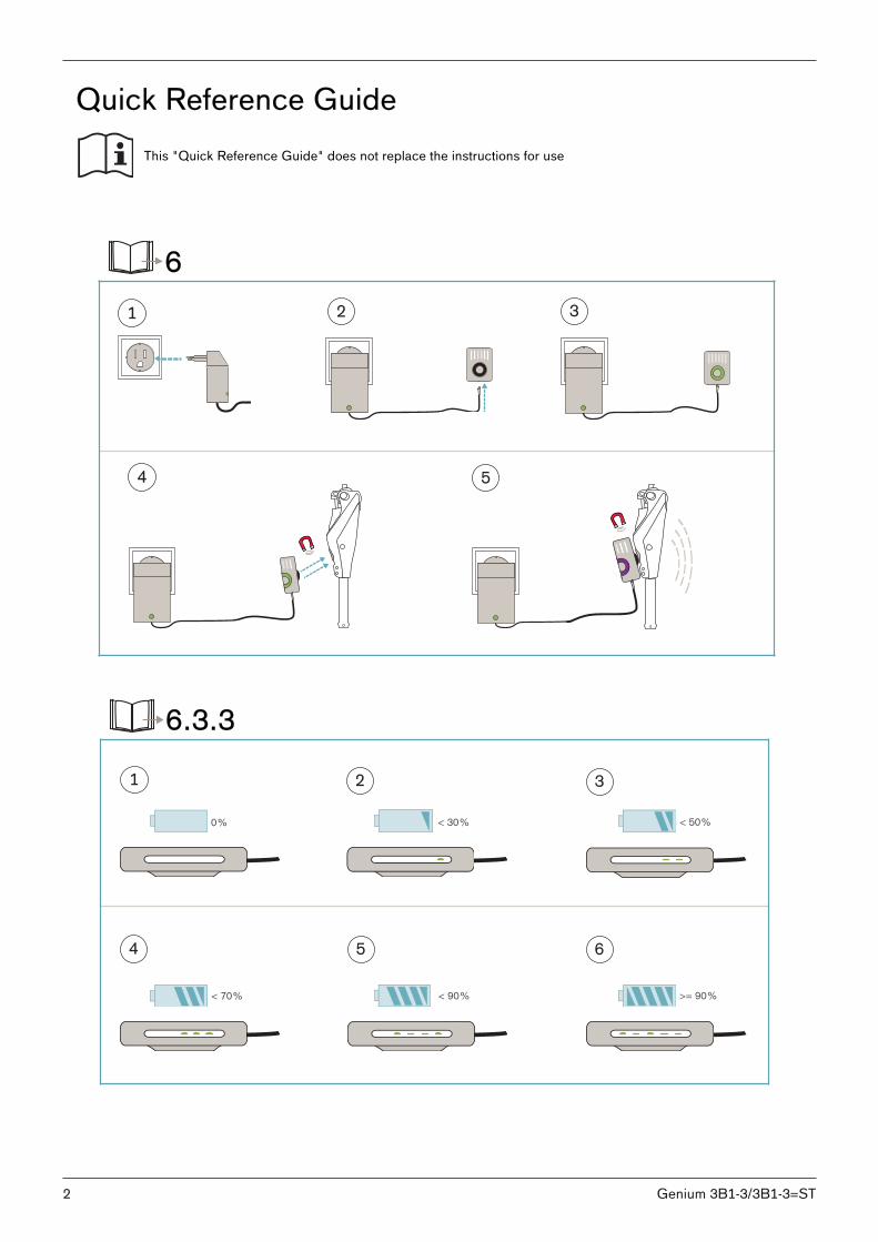
6.3.3
0% < 30% < 50%
< 70% < 90% >= 90%
1 2 3
4 5 6
2 Genium 3B1-3/3B1-3=ST
1 2 3 4
719R3 715H1=2
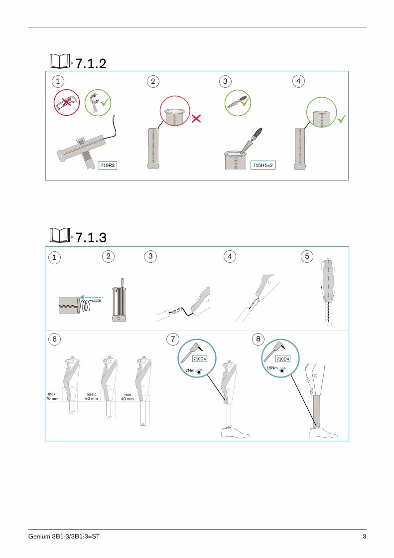
7.1.2
7Nm
710D415Nm
710D4
max70 mm
basic60 mm
min40 mm
1 2 3 4 5
6 7 8
7.1.3
3Genium 3B1-3/3B1-3=ST
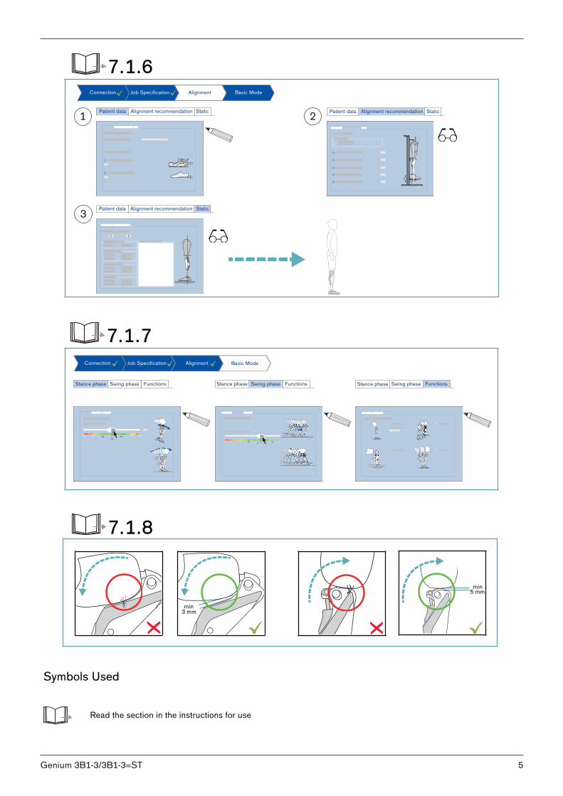
min3 mm
min 5 mm
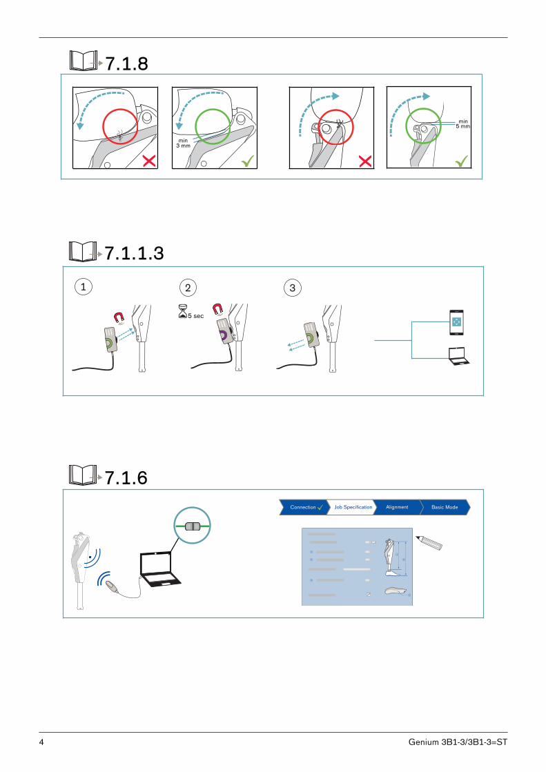
7.1.8
5 sec
1 2 3
7.1.1.3
Connection Job Specification Alignment Basic Mode
7.1.6
4 Genium 3B1-3/3B1-3=ST
Connection Job Specification Alignment Basic Mode
Patient data Alignment recommendation Static Patient data Alignment recommendation Static
Patient data Alignment recommendation Static
2
1
1
4
5
2
- +
3
0
7.1.6
3
21
Connection Job Specification Alignment Basic Mode
Stance phase Swing phase Functions Stance phase Swing phase Functions Stance phase Swing phase Functions
120 130140
150
160170 180
65
55 62 68 7060
7.1.7
min3 mm
min 5 mm
7.1.8
Symbols Used
Read the section in the instructions for use
5Genium 3B1-3/3B1-3=ST
Magnetic components
Tightening torque in the direction of rotation and screw geometryx-Nm
Use a torque wrench
Wrong
Right
Duration
Cockpit App
Use the adjustment software
A successful connection between the product and the adjustment software is established
Fill in the fields in the adjustment software
Check the values
6 Genium 3B1-3/3B1-3=ST
DE | INFORMATIONZusätzlich zu der gedruckten Gebrauchsanweisung, sind auch weitere Sprachen auf CD beigelegt (siehe rückseitigen Umschlag). Auf Anfrage können Sie eine gedruckte Gebrauchsanweisung kostenlos in der jeweiligen Landessprache unter der untenangegebenen Anschrift bestellen.
EN | INFORMATIONIn addition to the printed Instructions for Use, additional language versions are also included on CD (see back cover). You canorder a printed version of the Instructions for Use at no charge in the respective national language at the address below.
FR | INFORMATIONLe mode d‘emploi est disponible en d‘autres langues sur CD en supplément de la version imprimée (voir au dos de la couverture). Vous pouvez commander gratuitement une version imprimée du mode d‘emploi dans la langue de votre choix en envoyantvotre demande à l‘adresse indiquée ci-dessous.
ES | INFORMAĆIONAparte de las instrucciones de uso impresas, se incluye un CD con dichas instrucciones en otros idiomas (véase la solapa deldorso). Puede solicitar de forma gratuita unas instrucciones de uso impresas en el idioma de su país a la dirección que seindica más abajo.
IT | INFORMAZIONEIn aggiunta alle istruzioni per l‘uso in formato cartaceo, il CD contiene le istruzioni anche in altre lingue (vedere il retro dellacopertina). Su richiesta, potete ordinare gratuitamente le istruzioni per l‘uso in formato cartaceo nella relativa lingua del vostroPaese all‘indirizzo di seguito riportato.
PT | INFORMAÇÃOAdicionalmente ao manual de utilização impresso encontra-se incluído um CD com mais idiomas (consultar a contracapa). Apedido é possível encomendar gratuitamente um exemplar impresso do manual de utilização no respectivo idioma junto doendereço especificado.
NL | INFORMATIEDe gebruiksaanwijzing is behalve in gedrukte vorm ook in diverse andere talen bijgevoegd op cd (zie de achterzijde van deomslag). Een gedrukte gebruiksaanwijzing in de gewenste taal kunt u kosteloos bestellen op het hieronder vermelde adres.
SE | INFORMATIONSom komplement till den tryckta bruksanvisningen har dessutom ytterligare språk bifogats på CD (se baksidan av omslaget).Vid efterfrågan kan du utan kostnad beställa en tryckt bruksanvisning i det respektive språket under den angivna adressen.
DA | INFORMATIONSupplerende til brugsanvisningen på papir er der også vedlagt yderligere sprog på cd (se bagsiden af omslaget). På denoplyste adresse nedenfor kan du bestille en gratis brugsanvisning på papir på det pågældende sprog.
NO | INFORMASJOUI tillegg til den trykte bruksanvisningen er flere språk vedlagt på CD (se på baksiden omslaget). Ved forespørsel kan du bestilleen gratis trykt bruksanvisning i det gjeldende språket via adressen nedenfor.
FI | TIEDOTPainetun käyttöohjeen lisäksi tarjoaa oheinen CD-levy käyttöön myös lisää kieliä (katso kansilehden takapuoli). Painettukäyttöohje kunkin maan omalla kielellä on pyynnöstä tilattavissa maksutta alla ilmoitetusta osoitteesta.
CZ | INFORMACEKromě této vytištěné verze návodu k použití jsou na přiloženém CD k dispozici také další jazykové verze překladu (viz zadnístrana obalu). V případě požadavku si můžete na níže uvedené adrese zdarma objednat vytištěný návod k použití v příslušnémjazyce.
PL | INFORMACJADodatkowo do wydrukowanej instrukcji użytkowania dołączono na CD wersję w innych językach (patrz tył okładki). Na żądanieistnieje możliwość zamówienia bezpłatnie pod podanym poniżej adresem wydrukowanej instrukcji użytkowania w języku danegokraju.
SK | INFORMÁCIADodatočne ku vytlačenému návodu na používanie sú na CD uložené aj ďalšie jazyky (pozri zadnú obálku). Na požiadanie simôžete bezplatne objednať vytlačený návod na používanie v príslušnom jazyku krajiny na dole uvedenej adrese.
HU | INFORMATIONA kinyomtatott használati utasítást kiegészíti a további nyelveket tartalmazó, mellékelt CD (ld. a hátlapon lévő borítékot). Azalábbi címen, kérésre költségmentesen megrendelhet az adott ország nyelvén kinyomtatott használati utasítást.
HR | INFORMACIJADodatno uz tiskane upute za uporabu priloženi su i drugi jezici na CD-u (vidi poleđinu). Na upit možete na dolje navedenojadresi besplatno naručiti tiskane upute za uporabu na dotičnom jeziku.
7Genium 3B1-3/3B1-3=ST
TR | INFORMATIONBasılmış olan kullanım kılavuzuna ilave olarak CD'de daha fazla alternatif diller bulunmaktadır (bakınız zarfın arka yüzü). İsteküzerine ilgili dilde basılmış kullanım kılavuzunu aşağıda belirtilmiş olan adresten temin edebilirsiniz.
Ottobock Healthcare Products GmbHBrehmstraße 16 | 1110 Wien | Austria
[email protected] | Fax (+43-1) 526 79 85
8 Genium 3B1-3/3B1-3=ST
Foreword1 12............................................................................................................................................................Product description2 12..........................................................................................................................................Design2.1 12...............................................................................................................................................Function2.2 12............................................................................................................................................Combination possibilities2.3 13.....................................................................................................................Combination with an osseointegrated implant system2.3.1 13..............................................................................
Application3 14.........................................................................................................................................................Indications for use3.1 14...............................................................................................................................Conditions of use3.2 14................................................................................................................................Indications3.3 14.........................................................................................................................................Qualification3.4 14.......................................................................................................................................
Safety4 15..................................................................................................................................................................Explanation of warning symbols4.1 15............................................................................................................Structure of the safety instructions4.2 15........................................................................................................General safety instructions4.3 15...................................................................................................................Information on the Power Supply/Battery Charging4.4 17.................................................................................Battery charger information4.5 17..................................................................................................................Information on Alignment/Adjustment4.6 18....................................................................................................Information on Proximity to Certain Areas4.7 20...............................................................................................Information on Use4.8 20..............................................................................................................................Notes on the safety modes4.9 22...................................................................................................................Instructions for use with an osseointegrated implant system4.10 22.....................................................................Information on the use of a mobile device with the cockpit app4.11 22.................................................................
Scope of Delivery and Accessories5 23................................................................................................................Charging the battery6 24.........................................................................................................................................Connecting the power supply and battery charger6.1 24..................................................................................Charging the prosthesis battery6.2 24............................................................................................................Display of the current charge level6.3 25.........................................................................................................Display of battery charge level without additional devices6.3.1 25.........................................................................Display of the current charge level using the Cockpit app6.3.2 25........................................................................Display of the current charge level during the charging process6.3.3 25................................................................
Preparation for use7 26...........................................................................................................................................Alignment7.1 26...........................................................................................................................................Settings with the "X-Soft" adjustment software7.1.1 26.......................................................................................Introduction7.1.1.1 26........................................................................................................................................Data transfer between the product and the PC7.1.1.2 26.......................................................................................Preparing the product to connect to the adjustment software7.1.1.3 26....................................................................Shortening the Tube Adapter7.1.2 27................................................................................................................Installing the Tube Adapter7.1.3 27...................................................................................................................Adjusting the torsion moment on the 2R21 AXON tube adapter7.1.4 28.................................................................Bench alignment in alignment apparatus7.1.5 28................................................................................................Static alignment optimisation7.1.6 28................................................................................................................Dynamic alignment optimisation7.1.7 28............................................................................................................Checking the socket after bench alignment7.1.8 28............................................................................................Flexion stop7.1.9 29........................................................................................................................................Optional: Installing the foam cover7.2 29........................................................................................................
Cockpit app8 30........................................................................................................................................................System Requirements8.1 31..........................................................................................................................Initial connection between cockpit app and prosthesis8.2 31.............................................................................Starting the cockpit app for the first time8.2.1 31................................................................................................Control elements for cockpit app8.3 32..........................................................................................................Cockpit app navigation menu8.3.1 32...............................................................................................................
Table of contents
9Genium 3B1-3/3B1-3=ST
Table of contents
Managing components8.4 32........................................................................................................................Adding component8.4.1 33..............................................................................................................................Deleting a component8.4.2 33..........................................................................................................................Connecting component with multiple devices8.4.3 33.........................................................................................
Use9 34......................................................................................................................................................................Movement patterns in basic mode (mode 1)9.1 34...........................................................................................Standing9.1.1 34............................................................................................................................................Stance function9.1.1.1 34...................................................................................................................................Walking9.1.2 34.............................................................................................................................................Running short distances ("walk-to-run" function)9.1.3 35.....................................................................................Sitting down9.1.4 35.......................................................................................................................................Sitting9.1.5 35................................................................................................................................................Sitting function9.1.5.1 35...................................................................................................................................Standing up9.1.6 35.......................................................................................................................................Walking up stairs step-over-step9.1.7 36...........................................................................................................Overcoming obstacles9.1.8 36.........................................................................................................................Walking down stairs9.1.9 37............................................................................................................................Walking down a ramp9.1.10 37..........................................................................................................................Configuration for walking down stairs/ramp using the adjustment software9.1.11 37................................................Changing prosthesis settings9.2 37...............................................................................................................Changing the prosthesis setting using the cockpit app9.2.1 38............................................................................Overview of adjustment parameters in basic mode9.2.2 38..................................................................................Overview of adjustment parameters in MyModes9.2.3 39.....................................................................................Turning Bluetooth on the prosthesis on/off9.3 40.............................................................................................Switching Bluetooth off/on using the cockpit app9.3.1 40....................................................................................Querying the prosthesis status9.4 40..............................................................................................................Query status through cockpit app9.4.1 40.........................................................................................................Status display in the cockpit app9.4.2 40...........................................................................................................Mute mode (silent mode)9.5 40.....................................................................................................................Turning mute mode on/off using the Cockpit app9.5.1 40....................................................................................Deep sleep mode9.6 41................................................................................................................................Turning deep sleep mode on/off using the Cockpit app9.6.1 41...........................................................................OPG function (Optimised Physiological Gait)9.7 41.........................................................................................
MyModes10 42............................................................................................................................................................Switching MyModes with the cockpit app10.1 42..............................................................................................Switching MyModes using motion patterns10.2 43............................................................................................Switching from a MyMode back to basic mode10.3 44.......................................................................................
Additional operating states (modes)11 44..............................................................................................................Empty battery mode11.1 44.............................................................................................................................Mode for charging the prosthesis11.2 44..........................................................................................................Safety mode11.3 45.......................................................................................................................................Overheating mode11.4 45...............................................................................................................................
Storage and bleeding12 45.......................................................................................................................................Cleaning13 45.............................................................................................................................................................Maintenance14 46......................................................................................................................................................Identification of the product by the Service Center14.1 46..................................................................................
Legal information15 46..............................................................................................................................................Liability15.1 46..............................................................................................................................................Trademarks15.2 46........................................................................................................................................CE conformity15.3 46.....................................................................................................................................Local Legal Information15.4 47.......................................................................................................................
Technical data16 48...................................................................................................................................................Appendices17 50........................................................................................................................................................Symbols Used17.1 50....................................................................................................................................
10 Genium 3B1-3/3B1-3=ST
Table of contents
Operating states/error signals17.2 51..............................................................................................................Signals for operating states17.2.1 51..................................................................................................................Warnings/error signals17.2.2 52........................................................................................................................Error messages while establishing a connection with the cockpit app17.2.3 53........................................................Status signals17.2.4 54.....................................................................................................................................Directives and manufacturer’s declaration17.3 55..............................................................................................Electromagnetic environment17.3.1 55................................................................................................................
11Genium 3B1-3/3B1-3=ST
Table of contents
1 ForewordINFORMATION
Date of last update: 2018-03-23► Please read this document carefully before using the product.► Instruct the user in the proper and safe use of the product.► Please contact the manufacturer if you have questions about the product (e.g. regarding the start-up, use,
maintenance, unexpected operating behaviour or circumstances). Contact information can be found on theback page.
► Please keep this document in a safe place.
The product "Genium" is called the product/prosthesis/knee joint/component in the following.These instructions for use provide you with important information on the use, adaptation and handling of theproduct.Only put the product into use in accordance with the information contained in the accompanying documents supplied.
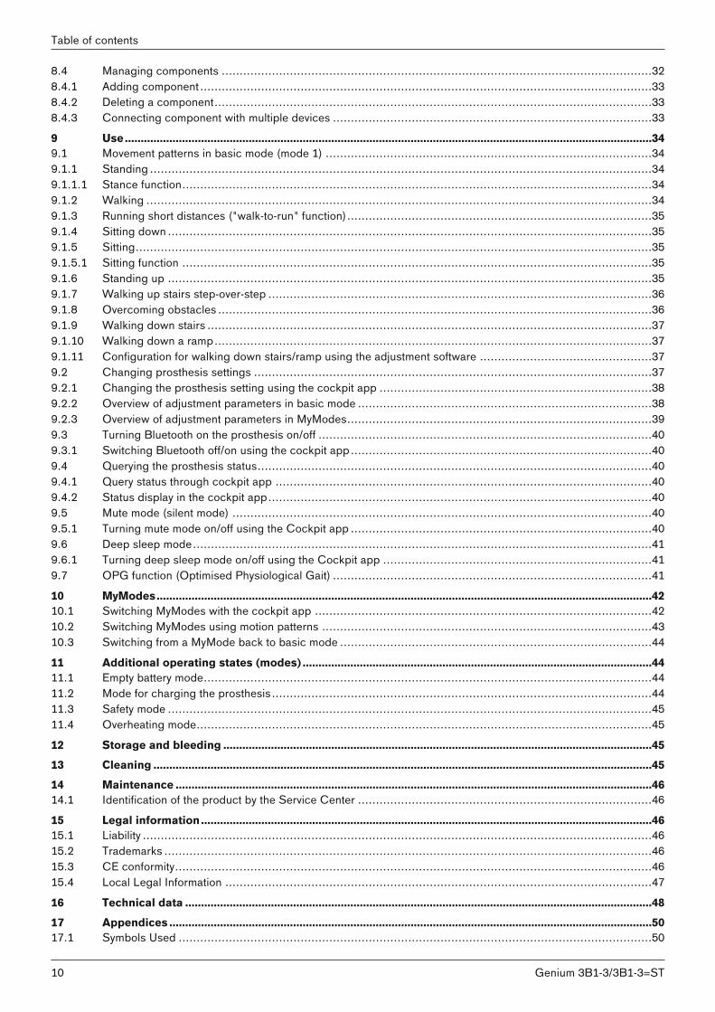
2 Product description2.1 DesignThe product consists of the following components:
87
6
5
4
3
2
11. Proximal pyramid adapter2. Optional flexion stops3. Battery4. Hydraulic unit5. LED (blue) as indicator for the Bluetooth connec
tion6. Receiver of the inductive charging unit7. Distal tube clamp screws8. Connecting cable for tube adapter
2.2 FunctionThis product features microprocessor control of the stance and swing phase.The microprocessor uses the measurements of an integrated sensor system as a basis to control a hydraulic unitthat influences the damping behaviour of the product.These sensor data are updated and evaluated 100 times per second. As a result, the behaviour of the product isadapted to the current motion situation (gait phase) dynamically and in real time.Thanks to the microprocessor-controlled stance and swing phase, the product can be individually adapted to theneeds of the patient.For this purpose, the product is configured with the X-Soft adjustment software.The product features MyModes for special motion types (e.g. cycling ...). These are pre-configured using theadjustment software and can be activated with special movement patterns and the Cockpit app (see Page 42).In case of a product malfunction, safety mode makes restricted operation possible. Resistance parameters that arepredefined by the product are configured for this purpose (see Page 45).Empty battery mode permits safe walking when the battery is drained. Resistance parameters that are predefinedby the product are configured for this purpose (see Page 44).
12 Genium 3B1-3/3B1-3=ST
Foreword

The microprocessor-controlled hydraulic unit offers the following advantages• Approximation of the physiological gait pattern• Stability while standing and walking• Adaptation of product characteristics to various surfaces, inclines, gait situations and walking speeds
2.3 Combination possibilitiesThis product can be combined with the following Ottobock components:
Adapters• 4R104=60 double adapter, sliding• 4R104=75 double adapter, sliding• Rotation adapter: 4R57, 4R57=*• 4R41 lamination anchor with pyramid receiver• 4R43 lamination anchor with threaded connector• 4R89 lamination anchor with pyramid adapter• 4R111=N lamination anchor with threaded connect
or
• 4R111 lamination anchor with pyramid receiver• 4R116 lamination anchor with pyramid adapter• Lamination anchor with pyramid receiver and
angled arm: 4R119• 4R40 torsion adapter• 4R118 adapter plate• Quickchange: 4R10
Tube adapter• AXON tube adapter: 2R20• AXON tube adapter with torsion unit: 2R21
Cosmetic cover/protector• Foam cover: 3S26• 4X880=* Genium Protective Cover
Prosthetic feetThe maximum allowable patient weight depends on the foot size.• 1M10 Adjust• 1A30 Greissinger plus• 1C30 Trias • 1D35 Dynamic Motion • 1C40 C-Walk • 1C60 Triton • 1C61 Triton Vertical Shock • 1C62 Triton Harmony • 1C63 Triton Low Profile
• 1C64 Triton Heavy Duty • 1E56 Axtion • 1E57 Lo Rider • Challenger: 1E95 • 1B1 Meridium • Meridium: 1B1-2• 1C66 Triton smart ankle • 1C10 Terion • Empower: 1A1-1
Depending on the patient's weight, this knee joint may be combined with the 1C63 Triton Low Profile prosthetic foot and the 1A1-1 Empower prosthetic foot in the following foot sizes only (see following table).Please contact Ottobock customer service if you would like a combination outside the approved ranges.
Body weight Foot sizes 1C63 [cm] Foot sizes 1A1-1 [cm]up to 116 kg (up to 256 lbs) 21 to 30 25 to 30
117 kg to 125 kg (257 lbs to 275 lbs) 21 to 30 25 to 27126 kg to 130 kg (276 lbs to 286 lbs) 21 to 28 25 to 27131 kg to 150 kg (287 lbs to 330 lbs) 21 to 28 –
2.3.1 Combination with an osseointegrated implant systemThis product can be connected to a socket or to an osseointegrated, percutaneous implant system. In case of connection to an implant system, verify that the manufacturer of the implant system and the manufacturers of the corresponding exoprosthetic components/adapters also permit this combination. It must be ensured thatall indications/contraindications, the field of application, the conditions of use and all safety instructions are complied with for the implant system, corresponding exoprosthetic components, corresponding adapters and for theknee joint.Among other things, this relates to the body weight, mobility grade, type of activity, load capacity of the implant andbone anchoring, freedom from pain under functional load and compliance with the permissible ambient conditions(see Page 48).
13Genium 3B1-3/3B1-3=ST
Product description
Please ensure that the qualified personnel applying the product is not only authorised for fitting this knee joint, butalso for the connection to the osseointegrated implant system.
3 Application3.1 Indications for useThe product is to be used solely for lower limb exoprosthetic fittings.
3.2 Conditions of useThe product was developed for everyday use and must not be used for unusual activities. These unusual activitiesinclude, for example, extreme sports (free climbing, parachuting, paragliding, etc.).Permissible ambient conditions are described in the technical data (see Page 48).The product is intended exclusively for use on one patient. Use of the product by another person is not approvedby the manufacturer.Our components perform optimally when paired with appropriate components based upon weight and mobilitygrades identifiable by our MOBIS classification information and which have appropriate modular connectors.
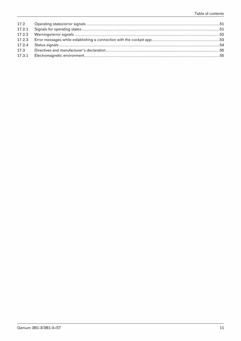
Knee joint with attached 2R20 AXON tube adapter
m°
kg
The product is recommended for mobility grade 2 (restricted outdoor walker), mobility grade 3(unrestricted outdoor walker) and mobility grade 4 (unrestricted outdoor walker with particularlyhigh demands). Approved for a body weight of up to 150 kg (330 lbs).
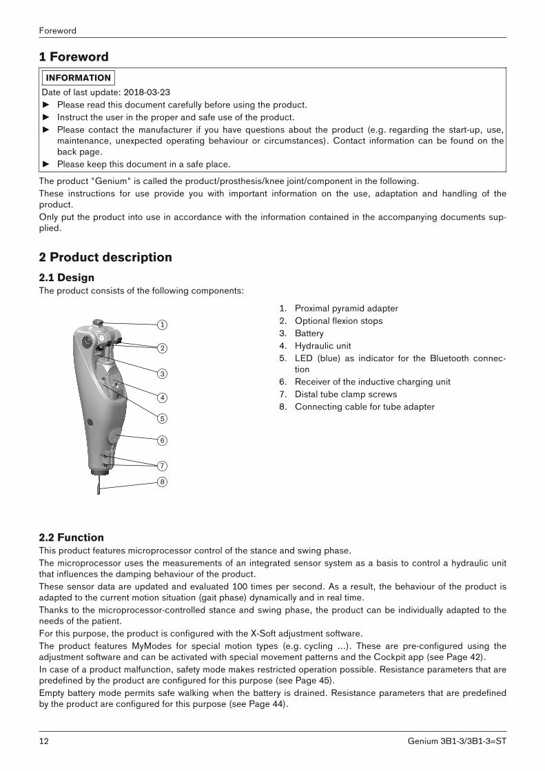
Knee joint with attached 2R21 AXON tube adapter with torsion
m°
kg
The product is recommended for mobility grade 2 (restricted outdoor walker), mobility grade 3(unrestricted outdoor walker) and mobility grade 4 (unrestricted outdoor walker with particularlyhigh demands). Approved for a body weight of up to 125 kg (275 lbs).
3.3 Indications• For patients with knee disarticulation, transfemoral amputation and hip disarticulation (patients with hip disar
ticulation or hemipelvectomy must be fitted with the 7E10=* Helix3D hip joint).• For unilateral or bilateral amputation• Dysmelia patients with residual limb characteristics corresponding to knee disarticulation, transfemoral ampu
tation or hip disarticulation• The patient must fulfil the physical and mental requirements for perceiving visual/acoustic signals and/or mech
anical vibrations.
3.4 QualificationThe product may be fitted only by qualified personnel authorised by Ottobock after completing the correspondingtraining.If the product is to be connected to an osseointegrated implant system, the qualified personnel must also beauthorised for the connection to the osseointegrated implant system.
14
Application
Genium 3B1-3/3B1-3=ST
4 Safety4.1 Explanation of warning symbols
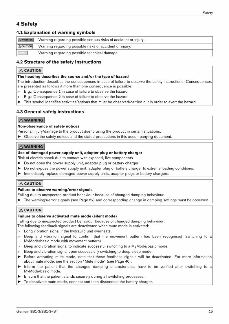
WARNING Warning regarding possible serious risks of accident or injury.CAUTION Warning regarding possible risks of accident or injury.
NOTICE Warning regarding possible technical damage.
4.2 Structure of the safety instructions
CAUTIONThe heading describes the source and/or the type of hazardThe introduction describes the consequences in case of failure to observe the safety instructions. Consequencesare presented as follows if more than one consequence is possible:> E.g.: Consequence 1 in case of failure to observe the hazard> E.g.: Consequence 2 in case of failure to observe the hazard► This symbol identifies activities/actions that must be observed/carried out in order to avert the hazard.
4.3 General safety instructions
WARNINGNon-observance of safety noticesPersonal injury/damage to the product due to using the product in certain situations.► Observe the safety notices and the stated precautions in this accompanying document.
WARNINGUse of damaged power supply unit, adapter plug or battery chargerRisk of electric shock due to contact with exposed, live components.► Do not open the power supply unit, adapter plug or battery charger.► Do not expose the power supply unit, adapter plug or battery charger to extreme loading conditions.► Immediately replace damaged power supply units, adapter plugs or battery chargers.
CAUTIONFailure to observe warning/error signalsFalling due to unexpected product behaviour because of changed damping behaviour.► The warnings/error signals (see Page 52) and corresponding change in damping settings must be observed.
CAUTIONFailure to observe activated mute mode (silent mode)Falling due to unexpected product behaviour because of changed damping behaviour.The following feedback signals are deactivated when mute mode is activated:> Long vibration signal if the hydraulic unit overheats.> Beep and vibration signal to confirm that the movement pattern has been recognised (switching to a
MyMode/basic mode with movement pattern).> Beep and vibration signal to indicate successful switching to a MyMode/basic mode.> Beep and vibration signal upon successfully switching to deep sleep mode.► Before activating mute mode, note that these feedback signals will be deactivated. For more information
about mute mode, see the section "Mute mode" (see Page 40). ► Inform the patient that the changed damping characteristics have to be verified after switching to a
MyMode/basic mode.► Ensure that the patient stands securely during all switching processes.► To deactivate mute mode, connect and then disconnect the battery charger.
15Genium 3B1-3/3B1-3=ST
Safety
CAUTIONIndependent user manipulation of system componentsFalling due to breakage of load-bearing components or malfunction of the product.► Manipulations to the product other than the tasks described in these instructions for use are not permitted.► The battery may only be handled by Ottobock authorised, qualified personnel (no replacement by the user).► The product and any damaged components may only be opened and repaired by authorised, qualified
Ottobock personnel.
CAUTIONMechanical stress on the product> Falling due to unexpected product behaviour as the result of a malfunction.> Falling due to breakage of load-bearing components.> Skin irritation due to defects on the hydraulic unit with leakage of liquid.► Do not subject the product to mechanical vibrations or impacts.► Check the product for visible damage before each use.
CAUTIONUse of the product when battery charge level is too lowFalling due to unexpected behaviour of the prosthesis because of changed damping behaviour.► Check the current charge level before use and charge the prosthesis if required.► Note that the operating time of the product may be reduced at low ambient temperatures or due to ageing of
the battery.
CAUTIONRisk of pinching in the joint flexion areaInjuries due to pinching of body parts.► Ensure that fingers/body parts or soft tissue of the residual limb are not in this area when bending the joint.
CAUTIONPenetration of dirt and humidity into the product> Falling due to unexpected product behaviour as the result of a malfunction.> Falling due to breakage of load-bearing components.► Ensure that no solid particles or foreign objects can penetrate into the product.► The knee joint is weather-proof but not resistant to corrosion. Therefore, the knee joint should not come into
contact with salt water, chlorinated water or other solutions (such as soap or shower gel, and body and/orwound fluids). Do not use the knee joint under extreme conditions like diving or jumping into water. The kneejoint is not designed for prolonged underwater use or prolonged submersion.
► After contact with water, remove the Protective Cover (if installed) and hold the prosthesis with the sole of thefoot facing up until the water has drained from the knee joint and tube adapter. Dry the knee joint and components with a lint-free cloth and allow the components to fully air dry.
► Should the knee joint or tube adapter come into contact with salt water, chlorinated water or other solutions (such as soap or shower gel, and body and/or wound fluids), promptly remove the Protective Cover (ifinstalled) and clean the knee joint. In order to do so, rinse knee joint, tube adapter and Protective Cover withfresh water and let them dry.
► In case of a malfunction after drying, the knee joint and tube adapter must be inspected by an authorisedOttobock Service Center.
► The knee joint is not resistant to penetration from water jets or steam.
CAUTIONMechanical stress during transport> Falling due to unexpected product behaviour as a result of a malfunction.> Falling due to breakage of load-bearing components.> Skin irritation due to defects on the hydraulic unit with leakage of liquid.► Only use the transport packaging for transportation.
16
Safety
Genium 3B1-3/3B1-3=ST
CAUTIONSigns of wear to the product componentsFalling due to damage or malfunction of the product.► In the interest of the patient's safety and in order to maintain operating reliability, the product must be ser
viced at regular intervals.
NOTICEImproper product careDamage to the product due to the use of incorrect cleaning agents.► Clean the product with a damp cloth only (fresh water).
INFORMATIONKnee joint movement noiseWhen using exoprosthetic knee joints, servomotor, hydraulic, pneumatic or brake load dependent control functions can cause movement noise. This kind of noise is normal and unavoidable. It generally does not indicate anyproblems. If movement noise increases noticeably during the lifecycle of the knee joint, the knee joint should beinspected by an authorised Ottobock Service Centre immediately.
4.4 Information on the Power Supply/Battery Charging
CAUTIONCharging the product without taking it offFalling due to unexpected product behaviour because of changed damping behaviour.► Instruct the patient that the product must be taken off before it is charged.
CAUTIONCharging the product with damaged power supply unit/charger/charger cableFalling due to unexpected behaviour of the product caused by insufficient charging.► Check the power supply unit, charger and charger cable for damage before use.► Replace any damaged power supply unit, charger or charger cable.
NOTICEUse of incorrect power supply unit/battery chargerDamage to product due to incorrect voltage, current or polarity.► Use only power supply units/battery chargers approved for this product by Ottobock (see instructions for use
and catalogues).
4.5 Battery charger informationNOTICE
Penetration of dirt and humidity into the productLack of proper charging functionality due to malfunction.► Ensure that neither solid particles nor liquids can penetrate into the product.
NOTICEMechanical stress on the power supply/battery chargerLack of proper charging functionality due to malfunction.► Do not subject the power supply/battery charger to mechanical vibrations or impacts.► Check the power supply/battery charger for visible damage before each use.
17Genium 3B1-3/3B1-3=ST
Safety
NOTICEOperating the power supply unit/charger outside of the permissible temperature rangeLack of proper charging functionality due to malfunction.► Only use the power supply unit/charger for charging within the allowable temperature range. The section
"Technical data" contains information on the allowable temperature range (see Page 48).
NOTICEIndependent changes or modifications carried out to the battery chargerLack of proper charging functionality due to malfunction.► Have any changes or modifications carried out only by Ottobock authorised, qualified personnel.
NOTICEContact of the battery charger with magnetic data storage devicesWiping of the data storage device.► Do not place the battery charger on credit cards, diskettes, audio or video cassettes.
4.6 Information on Alignment/Adjustment
CAUTIONUse of unsuitable prosthesis componentsFalling due to unexpected behaviour of the product or breakage of load-bearing components.► Use the product only in combination with components listed in the section "Combination possibilities" (see
Page 13).
CAUTIONImproper assembly of the screw connectionsFalling due to breakage or loosening of the screw connections.► Clean the threads before every installation.► Apply the specified tightening torque values for installation (see the section "Technical data").► Observe the instructions for securing the screw connections and the use of the correct length.
CAUTIONIncorrectly secured screwsFalling due to breakage of load-bearing components caused by screw connections coming loose.► After completing all settings, the set screws in the tube adapter must be secured before they are tightened to
the specified torque (see the section "Technical data" see Page 48).► The tube clamp screws must not be secured but only tightened to the specified torque.
CAUTIONIncorrect alignment or assemblyFalling due to damage to the prosthesis components.► Observe the alignment and assembly instructions.
18
Safety
Genium 3B1-3/3B1-3=ST
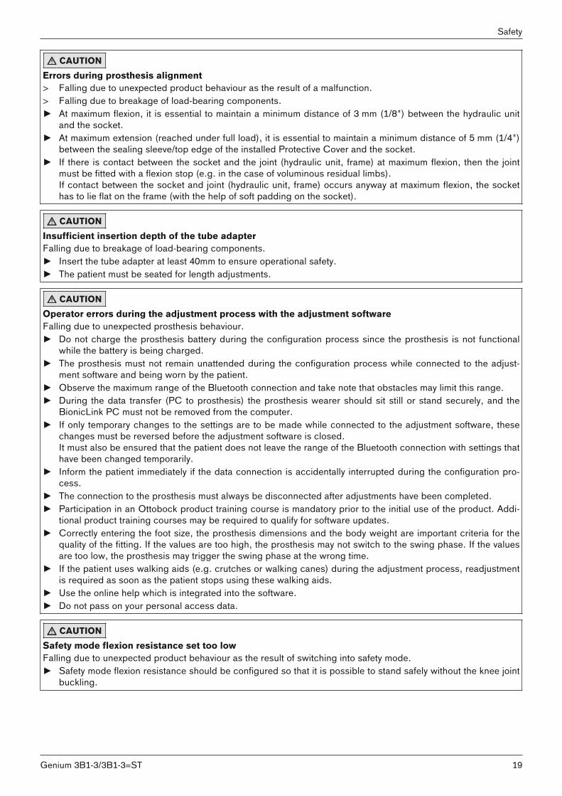
CAUTIONErrors during prosthesis alignment> Falling due to unexpected product behaviour as the result of a malfunction.> Falling due to breakage of load-bearing components.► At maximum flexion, it is essential to maintain a minimum distance of 3 mm (1/8") between the hydraulic unit
and the socket.► At maximum extension (reached under full load), it is essential to maintain a minimum distance of 5 mm (1/4")
between the sealing sleeve/top edge of the installed Protective Cover and the socket. ► If there is contact between the socket and the joint (hydraulic unit, frame) at maximum flexion, then the joint
must be fitted with a flexion stop (e.g. in the case of voluminous residual limbs).If contact between the socket and joint (hydraulic unit, frame) occurs anyway at maximum flexion, the sockethas to lie flat on the frame (with the help of soft padding on the socket).
CAUTIONInsufficient insertion depth of the tube adapterFalling due to breakage of load-bearing components.► Insert the tube adapter at least 40mm to ensure operational safety.► The patient must be seated for length adjustments.
CAUTIONOperator errors during the adjustment process with the adjustment softwareFalling due to unexpected prosthesis behaviour.► Do not charge the prosthesis battery during the configuration process since the prosthesis is not functional
while the battery is being charged.► The prosthesis must not remain unattended during the configuration process while connected to the adjust
ment software and being worn by the patient.► Observe the maximum range of the Bluetooth connection and take note that obstacles may limit this range.► During the data transfer (PC to prosthesis) the prosthesis wearer should sit still or stand securely, and the
BionicLink PC must not be removed from the computer.► If only temporary changes to the settings are to be made while connected to the adjustment software, these
changes must be reversed before the adjustment software is closed.It must also be ensured that the patient does not leave the range of the Bluetooth connection with settings thathave been changed temporarily.
► Inform the patient immediately if the data connection is accidentally interrupted during the configuration process.
► The connection to the prosthesis must always be disconnected after adjustments have been completed.► Participation in an Ottobock product training course is mandatory prior to the initial use of the product. Addi
tional product training courses may be required to qualify for software updates.► Correctly entering the foot size, the prosthesis dimensions and the body weight are important criteria for the
quality of the fitting. If the values are too high, the prosthesis may not switch to the swing phase. If the valuesare too low, the prosthesis may trigger the swing phase at the wrong time.
► If the patient uses walking aids (e.g. crutches or walking canes) during the adjustment process, readjustmentis required as soon as the patient stops using these walking aids.
► Use the online help which is integrated into the software.► Do not pass on your personal access data.
CAUTIONSafety mode flexion resistance set too lowFalling due to unexpected product behaviour as the result of switching into safety mode.► Safety mode flexion resistance should be configured so that it is possible to stand safely without the knee joint
buckling.
19Genium 3B1-3/3B1-3=ST
Safety
4.7 Information on Proximity to Certain Areas
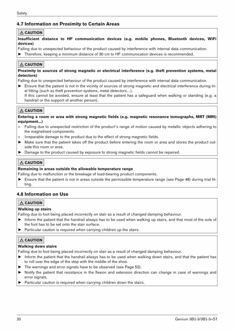
CAUTIONInsufficient distance to HF communication devices (e.g. mobile phones, Bluetooth devices, WiFidevices)Falling due to unexpected behaviour of the product caused by interference with internal data communication.► Therefore, keeping a minimum distance of 30 cm to HF communication devices is recommended.
CAUTIONProximity to sources of strong magnetic or electrical interference (e.g. theft prevention systems, metaldetectors)Falling due to unexpected behaviour of the product caused by interference with internal data communication.► Ensure that the patient is not in the vicinity of sources of strong magnetic and electrical interference during tri
al fitting (such as theft prevention systems, metal detectors...).If this cannot be avoided, ensure at least that the patient has a safeguard when walking or standing (e.g. ahandrail or the support of another person).
CAUTIONEntering a room or area with strong magnetic fields (e.g. magnetic resonance tomographs, MRT (MRI)equipment...) > Falling due to unexpected restriction of the product's range of motion caused by metallic objects adhering to
the magnetised components. > Irreparable damage to the product due to the effect of strong magnetic fields.► Make sure that the patient takes off the product before entering the room or area and stores the product out
side this room or area.► Damage to the product caused by exposure to strong magnetic fields cannot be repaired.
CAUTIONRemaining in areas outside the allowable temperature rangeFalling due to malfunction or the breakage of load-bearing product components.► Ensure that the patient is not in areas outside the permissible temperature range (see Page 48) during trial fit
ting.
4.8 Information on Use
CAUTIONWalking up stairsFalling due to foot being placed incorrectly on stair as a result of changed damping behaviour.► Inform the patient that the handrail always has to be used when walking up stairs, and that most of the sole of
the foot has to be set onto the stair surface.► Particular caution is required when carrying children up the stairs.
CAUTIONWalking down stairsFalling due to foot being placed incorrectly on stair as a result of changed damping behaviour.► Inform the patient that the handrail always has to be used when walking down stairs, and that the patient has
to roll over the edge of the step with the middle of the shoe.► The warnings and error signals have to be observed (see Page 52).► Notify the patient that resistance in the flexion and extension direction can change in case of warnings and
error signals.► Particular caution is required when carrying children down the stairs.
20
Safety
Genium 3B1-3/3B1-3=ST
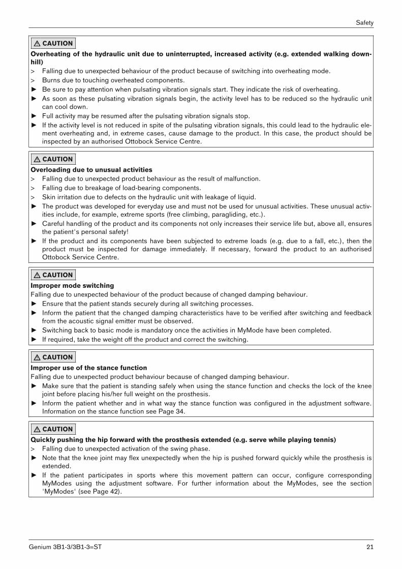
CAUTIONOverheating of the hydraulic unit due to uninterrupted, increased activity (e.g. extended walking downhill)> Falling due to unexpected behaviour of the product because of switching into overheating mode.> Burns due to touching overheated components.► Be sure to pay attention when pulsating vibration signals start. They indicate the risk of overheating.► As soon as these pulsating vibration signals begin, the activity level has to be reduced so the hydraulic unit
can cool down.► Full activity may be resumed after the pulsating vibration signals stop.► If the activity level is not reduced in spite of the pulsating vibration signals, this could lead to the hydraulic ele
ment overheating and, in extreme cases, cause damage to the product. In this case, the product should beinspected by an authorised Ottobock Service Centre.
CAUTIONOverloading due to unusual activities> Falling due to unexpected product behaviour as the result of malfunction.> Falling due to breakage of load-bearing components.> Skin irritation due to defects on the hydraulic unit with leakage of liquid.► The product was developed for everyday use and must not be used for unusual activities. These unusual activ
ities include, for example, extreme sports (free climbing, paragliding, etc.).► Careful handling of the product and its components not only increases their service life but, above all, ensures
the patient's personal safety!► If the product and its components have been subjected to extreme loads (e.g. due to a fall, etc.), then the
product must be inspected for damage immediately. If necessary, forward the product to an authorisedOttobock Service Centre.
CAUTIONImproper mode switchingFalling due to unexpected behaviour of the product because of changed damping behaviour.► Ensure that the patient stands securely during all switching processes.► Inform the patient that the changed damping characteristics have to be verified after switching and feedback
from the acoustic signal emitter must be observed.► Switching back to basic mode is mandatory once the activities in MyMode have been completed.► If required, take the weight off the product and correct the switching.
CAUTIONImproper use of the stance functionFalling due to unexpected product behaviour because of changed damping behaviour.► Make sure that the patient is standing safely when using the stance function and checks the lock of the knee
joint before placing his/her full weight on the prosthesis.► Inform the patient whether and in what way the stance function was configured in the adjustment software.
Information on the stance function see Page 34.
CAUTIONQuickly pushing the hip forward with the prosthesis extended (e.g. serve while playing tennis)> Falling due to unexpected activation of the swing phase.► Note that the knee joint may flex unexpectedly when the hip is pushed forward quickly while the prosthesis is
extended.► If the patient participates in sports where this movement pattern can occur, configure corresponding
MyModes using the adjustment software. For further information about the MyModes, see the section'MyModes' (see Page 42).
21Genium 3B1-3/3B1-3=ST
Safety

4.9 Notes on the safety modes
CAUTIONUsing the product in safety modeFalling due to unexpected product behaviour because of changed damping behaviour.► The warnings/error signals (see Page 52) have to be observed.► Particular caution is necessary when using a bicycle without a freewheel (with a fixed gear).
CAUTIONSafety mode cannot be activated due to malfunction caused by water penetration or mechanical damageFalling due to unexpected product behaviour because of changed damping behaviour.► Using the product when it is defective is prohibited.► The product must be inspected by an authorised Ottobock Service Centre.
CAUTIONSafety mode cannot be deactivatedFalling due to unexpected product behaviour because of changed damping behaviour.► If safety mode cannot be deactivated by recharging the battery, a permanent error has occurred.► Using the product when it is defective is prohibited.► The product must be inspected by an authorised Ottobock Service Centre.
CAUTIONSafety signal occurs (ongoing vibration)Falling due to unexpected product behaviour because of changed damping behaviour.► The warnings/error signals (see Page 52) have to be observed.► After the safety signal has been emitted, further use of the product is prohibited.► The product must be inspected by an authorised Ottobock Service Centre.
4.10 Instructions for use with an osseointegrated implant system
WARNINGHigh mechanical loads due to normal or unusual situations, such as falling> Overloading of the bone, which can lead to pain, loosening of the implant, necrosis or fracture among other
things.> Damage or breakage of the implant system or its components (safety components...).► Verify compliance with the fields of application, conditions of use and indications according to the information
of the manufacturers, both for the knee joint and for the implant system.► Note the instructions of the clinical personnel that indicated the use of the osseointegrated implant system.
4.11 Information on the use of a mobile device with the cockpit app
CAUTIONImproper use of the deviceFalling due to altered damping behaviour as a result of unexpected switching into MyMode.► Use the instructions for use (user) to instruct the patient on proper use of the device with the cockpit app.
CAUTIONImproper use of the setting parameters in the MyModesFalling due to unexpected product behaviour because of changed damping behaviour.► Instruct the patient regarding the functionality and adjustment options for all parameters of the MyModes.
22
Safety
Genium 3B1-3/3B1-3=ST
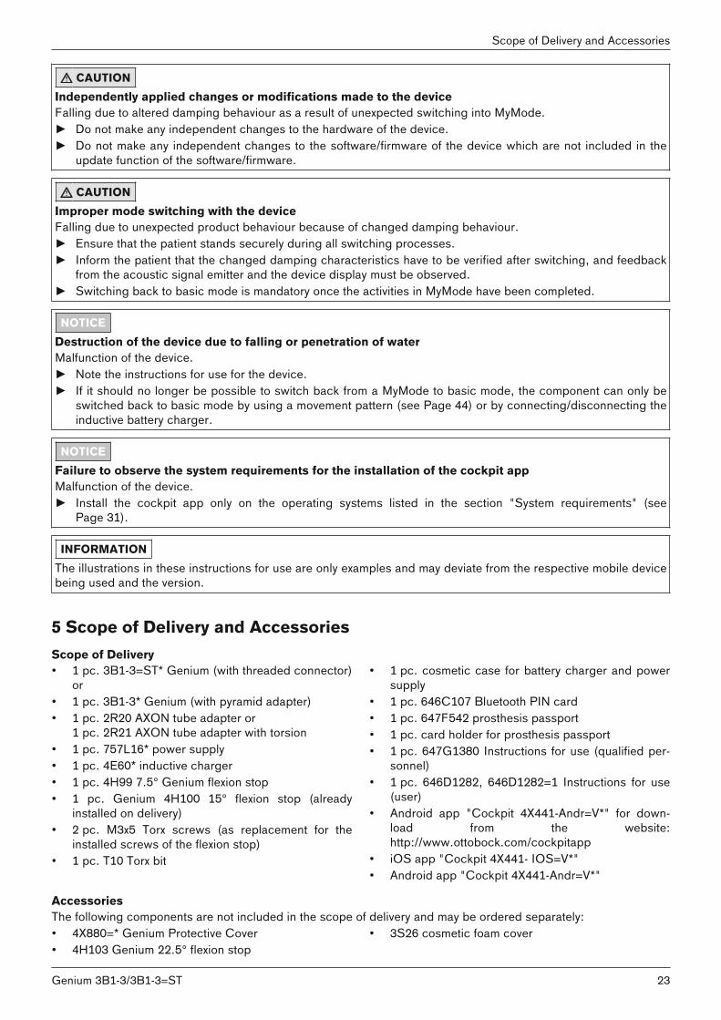
CAUTIONIndependently applied changes or modifications made to the deviceFalling due to altered damping behaviour as a result of unexpected switching into MyMode.► Do not make any independent changes to the hardware of the device.► Do not make any independent changes to the software/firmware of the device which are not included in the
update function of the software/firmware.
CAUTIONImproper mode switching with the deviceFalling due to unexpected product behaviour because of changed damping behaviour.► Ensure that the patient stands securely during all switching processes.► Inform the patient that the changed damping characteristics have to be verified after switching, and feedback
from the acoustic signal emitter and the device display must be observed.► Switching back to basic mode is mandatory once the activities in MyMode have been completed.
NOTICEDestruction of the device due to falling or penetration of waterMalfunction of the device.► Note the instructions for use for the device.► If it should no longer be possible to switch back from a MyMode to basic mode, the component can only be
switched back to basic mode by using a movement pattern (see Page 44) or by connecting/disconnecting theinductive battery charger.
NOTICEFailure to observe the system requirements for the installation of the cockpit appMalfunction of the device.► Install the cockpit app only on the operating systems listed in the section "System requirements" (see
Page 31).
INFORMATIONThe illustrations in these instructions for use are only examples and may deviate from the respective mobile devicebeing used and the version.
5 Scope of Delivery and AccessoriesScope of Delivery• 1 pc. 3B1-3=ST* Genium (with threaded connector)
or • 1 pc. 3B1-3* Genium (with pyramid adapter)• 1 pc. 2R20 AXON tube adapter or
1 pc. 2R21 AXON tube adapter with torsion• 1 pc. 757L16* power supply• 1 pc. 4E60* inductive charger• 1 pc. 4H99 7.5° Genium flexion stop• 1 pc. Genium 4H100 15° flexion stop (already
installed on delivery)• 2 pc. M3x5 Torx screws (as replacement for the
installed screws of the flexion stop)• 1 pc. T10 Torx bit
• 1 pc. cosmetic case for battery charger and powersupply
• 1 pc. 646C107 Bluetooth PIN card• 1 pc. 647F542 prosthesis passport• 1 pc. card holder for prosthesis passport• 1 pc. 647G1380 Instructions for use (qualified per
sonnel)• 1 pc. 646D1282, 646D1282=1 Instructions for use
(user)• Android app "Cockpit 4X441-Andr=V*" for down
load from the website:http://www.ottobock.com/cockpitapp
• iOS app "Cockpit 4X441- IOS=V*"• Android app "Cockpit 4X441-Andr=V*"
AccessoriesThe following components are not included in the scope of delivery and may be ordered separately:• 4X880=* Genium Protective Cover• 4H103 Genium 22.5° flexion stop
• 3S26 cosmetic foam cover
23Genium 3B1-3/3B1-3=ST
Scope of Delivery and Accessories

• 3F1=2• 4X258 installation tool for inductive charger• 4X259 installation ring for inductive charger
• "X-Soft 4X1=V1.8" or higher adjustment softwareUpdate from 4X1=V1.0, V1.2, V1.6 with Internetdownload
6 Charging the batteryThe following points must be observed when charging the battery:• With average use, the capacity of the fully charged battery is sufficient for about 5 days.• We recommend charging the product once a day when used by the patient on a daily basis.• When used daily, the complete charging unit (power supply – battery charger) may remain plugged into the
wall socket.• The battery should be charged for at least 3 hours prior to initial use.• Note the permissible temperature range for charging the battery (see Page 48).• Use the 757L16* power supply and 4E60* battery charger to charge the battery.• The distance between the battery charger and the receiver on the product must not exceed 2 mm. • The tube adapter must be connected before disconnecting the battery charger, otherwise an error message
will result (see Page 52).
6.1 Connecting the power supply and battery charger
1 2 3
1) Slide the country-specific plug adapter onto the power supply until it locks into place (see fig. 1).2) Connect the round, three-pin plug of the power supply to the receptacle on the battery charger (see fig. 2) so
that the plug locks into place.INFORMATION: Ensure correct polarity (guide lug). Do not use force when connecting the cable plugto the battery charger.
3) Plug the power supply unit into the outlet (see fig. 3).→ The green LED on the back of the power supply lights up.→ The LED ring (status indicator) on the rear of the charger lights up green to indicate the correct connection
to the power supply. → If the green LED on the power supply and the LED ring on the battery charger do not light up, there is an error
(see Page 52).
6.2 Charging the prosthesis batteryINFORMATION
When the Protective Cover is installed, the battery charger cable has to point to the upper closure. A correct kneejoint charging process is only ensured with this alignment.
24
Charging the battery
Genium 3B1-3/3B1-3=ST
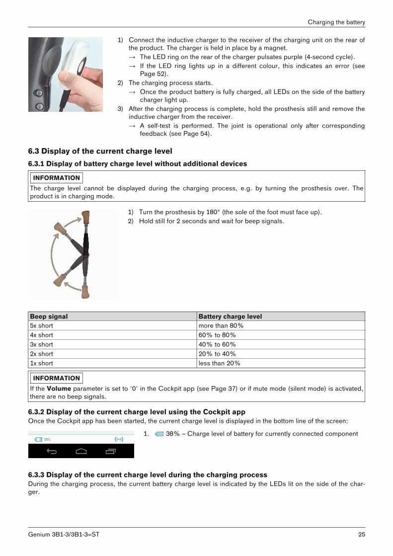
1) Connect the inductive charger to the receiver of the charging unit on the rear ofthe product. The charger is held in place by a magnet.→ The LED ring on the rear of the charger pulsates purple (4-second cycle).→ If the LED ring lights up in a different colour, this indicates an error (see
Page 52).2) The charging process starts.
→ Once the product battery is fully charged, all LEDs on the side of the batterycharger light up.
3) After the charging process is complete, hold the prosthesis still and remove theinductive charger from the receiver.→ A self-test is performed. The joint is operational only after corresponding
feedback (see Page 54).
6.3 Display of the current charge level6.3.1 Display of battery charge level without additional devices
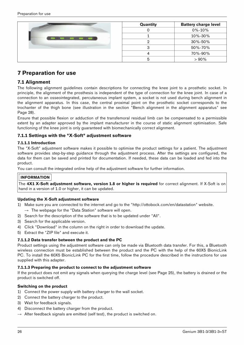
INFORMATIONThe charge level cannot be displayed during the charging process, e.g. by turning the prosthesis over. Theproduct is in charging mode.
1) Turn the prosthesis by 180° (the sole of the foot must face up).2) Hold still for 2 seconds and wait for beep signals.
Beep signal Battery charge level5x short more than 80%4x short 60% to 80%3x short 40% to 60%2x short 20% to 40%1x short less than 20%
INFORMATIONIf the Volume parameter is set to '0' in the Cockpit app (see Page 37) or if mute mode (silent mode) is activated,there are no beep signals.
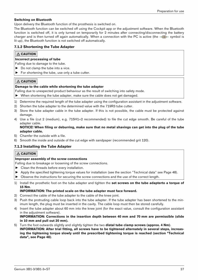
6.3.2 Display of the current charge level using the Cockpit appOnce the Cockpit app has been started, the current charge level is displayed in the bottom line of the screen:
1. 38% – Charge level of battery for currently connected component
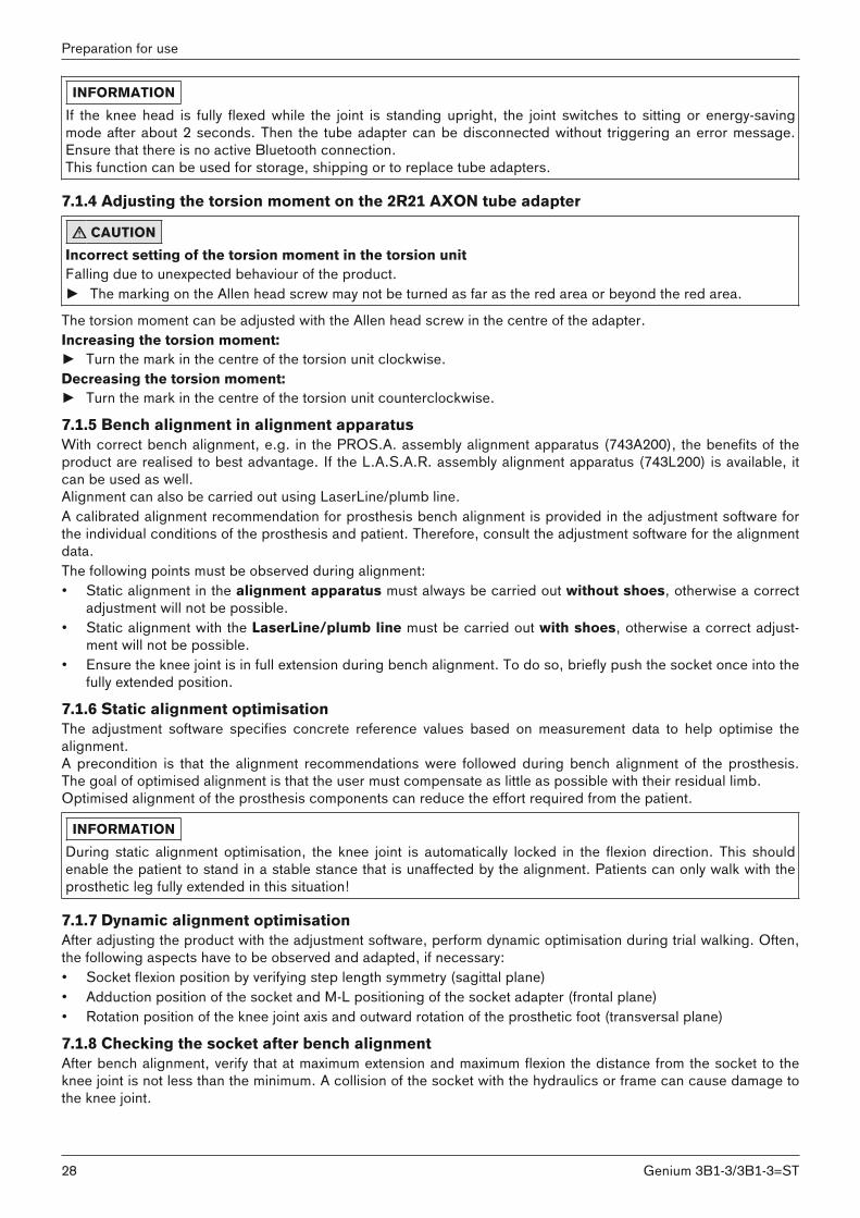
6.3.3 Display of the current charge level during the charging processDuring the charging process, the current battery charge level is indicated by the LEDs lit on the side of the charger.
25Genium 3B1-3/3B1-3=ST
Charging the battery
Quantity Battery charge level0 0%-10%1 10%-30%2 30%-50%3 50%-70%4 70%-90%5 > 90%
7 Preparation for use7.1 AlignmentThe following alignment guidelines contain descriptions for connecting the knee joint to a prosthetic socket. Inprinciple, the alignment of the prosthesis is independent of the type of connection for the knee joint. In case of aconnection to an osseointegrated, percutaneous implant system, a socket is not used during bench alignment inthe alignment apparatus. In this case, the central proximal point on the prosthetic socket corresponds to thetrochanter of the thigh bone (see illustration in the section "Bench alignment in the alignment apparatus" seePage 28). Ensure that possible flexion or adduction of the transfemoral residual limb can be compensated to a permissibleextent by an adapter approved by the implant manufacturer in the course of static alignment optimisation. Safefunctioning of the knee joint is only guaranteed with biomechanically correct alignment.
7.1.1 Settings with the "X-Soft" adjustment software7.1.1.1 IntroductionThe "X-Soft" adjustment software makes it possible to optimise the product settings for a patient. The adjustmentsoftware provides step-by-step guidance through the adjustment process. After the settings are configured, thedata for them can be saved and printed for documentation. If needed, these data can be loaded and fed into theproduct.You can consult the integrated online help of the adjustment software for further information.
INFORMATIONThe 4X1 X-Soft adjustment software, version 1.8 or higher is required for correct alignment. If X-Soft is onhand in a version of 1.0 or higher, it can be updated.
Updating the X-Soft adjustment software1) Make sure you are connected to the internet and go to the "http://ottobock.com/en/datastation" website.
→ The webpage for the "Data Station" software will open.2) Search for the description of the software that is to be updated under "All".3) Search for the applicable version.4) Click "Download" in the column on the right in order to download the update.5) Extract the "ZIP file" and execute it.
7.1.1.2 Data transfer between the product and the PCProduct settings using the adjustment software can only be made via Bluetooth data transfer. For this, a Bluetoothwireless connection must be established between the product and the PC with the help of the 60X5 BionicLinkPC. To install the 60X5 BionicLink PC for the first time, follow the procedure described in the instructions for usesupplied with this adapter.
7.1.1.3 Preparing the product to connect to the adjustment softwareIf the product does not emit any signals when querying the charge level (see Page 25), the battery is drained or theproduct is switched off.
Switching on the product1) Connect the power supply with battery charger to the wall socket.2) Connect the battery charger to the product.3) Wait for feedback signals.4) Disconnect the battery charger from the product.→ After feedback signals are emitted (self test), the product is switched on.
26
Preparation for use
Genium 3B1-3/3B1-3=ST
Switching on BluetoothUpon delivery the Bluetooth function of the prosthesis is switched on.The Bluetooth function can be switched off using the Cockpit app or the adjustment software. When the Bluetoothfunction is switched off, it is only turned on temporarily for 2 minutes after connecting/disconnecting the batterycharger and is then turned off again automatically. When a connection with the PC is active (the symbol islit up), the Bluetooth function is not switched off automatically.
7.1.2 Shortening the Tube Adapter
CAUTIONIncorrect processing of tubeFalling due to damage to the tube.► Do not clamp the tube into a vice.► For shortening the tube, use only a tube cutter.
CAUTIONDamage to the cable while shortening the tube adapterFalling due to unexpected product behaviour as the result of switching into safety mode.► When shortening the tube adapter, make sure the cable does not get damaged.
1) Determine the required length of the tube adapter using the configuration assistant in the adjustment software.2) Shorten the tube adapter to the determined value with the 719R3 tube cutter.3) Store the tube adapter cable in the tube adapter. If this is not possible, the cable must be protected against
damage.4) Use a file (cut 2 (medium), e.g. 715H1=2 recommended) to file the cut edge smooth. Be careful of the tube
adapter cable.NOTICE! When filing or deburring, make sure that no metal shavings can get into the plug of the tubeadapter cable.
5) Chamfer the outside with a file.6) Smooth the inside and outside of the cut edge with sandpaper (recommended grit 120).
7.1.3 Installing the Tube Adapter
CAUTIONImproper assembly of the screw connectionsFalling due to breakage or loosening of the screw connections.► Clean the threads before every installation.► Apply the specified tightening torque values for installation (see the section "Technical data" see Page 48).► Observe the instructions for securing the screw connections and the use of the correct length.
1) Install the prosthetic foot on the tube adapter and tighten the set screws on the tube adapterto a torque of15 Nm.INFORMATION: The printed scale on the tube adapter must face forward.
2) Connect the cable of the tube adapter to the cable of the knee joint.3) Push the protruding cable loop back into the tube adapter. If the tube adapter has been shortened to the min
imum length, the plug must be inserted in the cavity. The cable loop must then be stored carefully.4) Insert the tube adapter about 60 mm into the knee joint (for the exact value, consult the configuration assistant
in the adjustment software).INFORMATION: Corrections in the insertion depth between 40 mm and 70 mm are permissible (slidein 10 mm and pull out 20 mm).
5) Turn the foot outwards slightly and slightly tighten the two distal tube clamp screws (approx. 4 Nm).INFORMATION: After trial fitting, all screws have to be tightened alternately in several steps, increasing the tightening torque slowly until the prescribed tightening torque is reached (section "Technicaldata", see Page 48).
27Genium 3B1-3/3B1-3=ST
Preparation for use
INFORMATIONIf the knee head is fully flexed while the joint is standing upright, the joint switches to sitting or energy-savingmode after about 2 seconds. Then the tube adapter can be disconnected without triggering an error message.Ensure that there is no active Bluetooth connection.This function can be used for storage, shipping or to replace tube adapters.
7.1.4 Adjusting the torsion moment on the 2R21 AXON tube adapter
CAUTIONIncorrect setting of the torsion moment in the torsion unitFalling due to unexpected behaviour of the product.► The marking on the Allen head screw may not be turned as far as the red area or beyond the red area.
The torsion moment can be adjusted with the Allen head screw in the centre of the adapter.Increasing the torsion moment:► Turn the mark in the centre of the torsion unit clockwise.Decreasing the torsion moment:► Turn the mark in the centre of the torsion unit counterclockwise.
7.1.5 Bench alignment in alignment apparatusWith correct bench alignment, e.g. in the PROS.A. assembly alignment apparatus (743A200), the benefits of theproduct are realised to best advantage. If the L.A.S.A.R. assembly alignment apparatus (743L200) is available, itcan be used as well.Alignment can also be carried out using LaserLine/plumb line.A calibrated alignment recommendation for prosthesis bench alignment is provided in the adjustment software forthe individual conditions of the prosthesis and patient. Therefore, consult the adjustment software for the alignmentdata. The following points must be observed during alignment:• Static alignment in the alignment apparatus must always be carried out without shoes, otherwise a correct
adjustment will not be possible.• Static alignment with the LaserLine/plumb line must be carried out with shoes, otherwise a correct adjust
ment will not be possible.• Ensure the knee joint is in full extension during bench alignment. To do so, briefly push the socket once into the
fully extended position.
7.1.6 Static alignment optimisationThe adjustment software specifies concrete reference values based on measurement data to help optimise thealignment.A precondition is that the alignment recommendations were followed during bench alignment of the prosthesis.The goal of optimised alignment is that the user must compensate as little as possible with their residual limb.Optimised alignment of the prosthesis components can reduce the effort required from the patient.
INFORMATIONDuring static alignment optimisation, the knee joint is automatically locked in the flexion direction. This shouldenable the patient to stand in a stable stance that is unaffected by the alignment. Patients can only walk with theprosthetic leg fully extended in this situation!
7.1.7 Dynamic alignment optimisationAfter adjusting the product with the adjustment software, perform dynamic optimisation during trial walking. Often,the following aspects have to be observed and adapted, if necessary:• Socket flexion position by verifying step length symmetry (sagittal plane)• Adduction position of the socket and M-L positioning of the socket adapter (frontal plane)• Rotation position of the knee joint axis and outward rotation of the prosthetic foot (transversal plane)
7.1.8 Checking the socket after bench alignmentAfter bench alignment, verify that at maximum extension and maximum flexion the distance from the socket to theknee joint is not less than the minimum. A collision of the socket with the hydraulics or frame can cause damage tothe knee joint.
28
Preparation for use
Genium 3B1-3/3B1-3=ST

Verification at maximum flexion
If the distance between the socket and hydraulics is not sufficient, the hydraulicsmay be damaged. Check the distance as follows:1) Bring the knee joint with socket to maximum flexion.2) Check the available distance between the hydraulics and socket. It must be at
least 3 mm.INFORMATION: If the distance is less, a flexion stop has to be installed oran existing flexion stop replaced with a larger one. For information on theflexion stop, see the next section.
Verification at maximum extension
If the distance between the socket and sealing sleeve/top edge of the installed protective cover is not sufficient, the frame may be damaged. Check the distance as follows:1) Bring the knee joint with socket to maximum extension.2) Check the available distance between the sealing sleeve/top edge of the
installed protective cover and socket. It must be at least 5 mm.
7.1.9 Flexion stopThe knee joint comes fitted with a flexion stop upon delivery. This reduces the maximum flexion angle by 15°, thuspreventing the socket from coming into contact with the hydraulic unit.To limit the flexion angle, the knee joint can be equipped with the following flexion stops:• 4H99 flexion stop (in scope of delivery): Reduction of the maximum flexion angle by 7.5°• 4H100 flexion stop (already installed): reduction of the maximum flexion angle by 15°• 4H103 flexion stop (optional accessory): Reduction of the maximum flexion angle by 22.5°The flexion stop can be removed to increase the flexion angle. In this case, it must be ensured that the socket andthe hydraulic unit do not collide (see Page 28).
Removing the flexion stop1) Use an appropriate screwdriver to loosen the screws on the flexion stop (left and
right of the piston rod).2) Use the screwdriver to take the flexion stop out of the joint.
INFORMATION: Do not insert the screws without the flexion stop!
Inserting the flexion stop1) Insert the flexion stop.2) Secure the screws with 636K13 thread lock.3) Insert the screws.4) Tighten the screws to 0.6 Nm with the 710D17 torque wrench.
7.2 Optional: Installing the foam coverIf a cosmetic foam cover is installed on the knee joint, the inductive charging receiver has to be moved.
29Genium 3B1-3/3B1-3=ST
Preparation for use
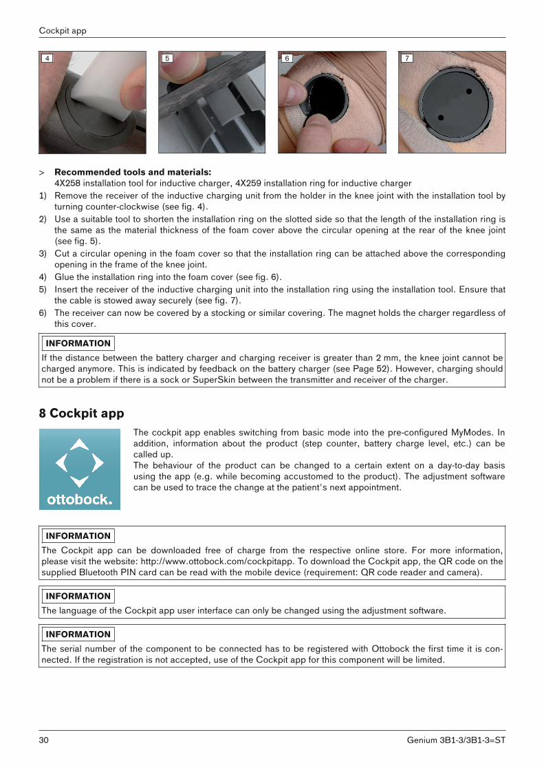
4 5 6 7
> Recommended tools and materials:4X258 installation tool for inductive charger, 4X259 installation ring for inductive charger
1) Remove the receiver of the inductive charging unit from the holder in the knee joint with the installation tool byturning counter-clockwise (see fig. 4).
2) Use a suitable tool to shorten the installation ring on the slotted side so that the length of the installation ring isthe same as the material thickness of the foam cover above the circular opening at the rear of the knee joint(see fig. 5).
3) Cut a circular opening in the foam cover so that the installation ring can be attached above the correspondingopening in the frame of the knee joint.
4) Glue the installation ring into the foam cover (see fig. 6).5) Insert the receiver of the inductive charging unit into the installation ring using the installation tool. Ensure that
the cable is stowed away securely (see fig. 7).6) The receiver can now be covered by a stocking or similar covering. The magnet holds the charger regardless of
this cover.
INFORMATIONIf the distance between the battery charger and charging receiver is greater than 2 mm, the knee joint cannot becharged anymore. This is indicated by feedback on the battery charger (see Page 52). However, charging shouldnot be a problem if there is a sock or SuperSkin between the transmitter and receiver of the charger.
8 Cockpit appThe cockpit app enables switching from basic mode into the pre-configured MyModes. Inaddition, information about the product (step counter, battery charge level, etc.) can becalled up.The behaviour of the product can be changed to a certain extent on a day-to-day basisusing the app (e.g. while becoming accustomed to the product). The adjustment softwarecan be used to trace the change at the patient's next appointment.
INFORMATIONThe Cockpit app can be downloaded free of charge from the respective online store. For more information,please visit the website: http://www.ottobock.com/cockpitapp. To download the Cockpit app, the QR code on thesupplied Bluetooth PIN card can be read with the mobile device (requirement: QR code reader and camera).
INFORMATIONThe language of the Cockpit app user interface can only be changed using the adjustment software.
INFORMATIONThe serial number of the component to be connected has to be registered with Ottobock the first time it is connected. If the registration is not accepted, use of the Cockpit app for this component will be limited.
30
Cockpit app
Genium 3B1-3/3B1-3=ST
INFORMATIONBluetooth on the prosthesis must be turned on in order to use the Cockpit app.If Bluetooth is switched off, it can be turned on by turning the prosthesis upside-down (sole of the foot must pointup) or by connecting/disconnecting the battery charger. Bluetooth is then turned on for approx. 2 minutes. Duringthis time, the app must be started and used to establish a connection. If required, Bluetooth on the prosthesis canbe switched on permanently afterwards (see Page 40).
8.1 System RequirementsThe functioning of the Cockpit app is assured on devices that support the following operating systems:• iOS (for iPhone, iPad, iPod): version 9.3 or higher. The mobile device has to support Bluetooth 4.0 (BT LE).• Android: version 4.0.3 or higher
8.2 Initial connection between cockpit app and prosthesisThe following points should be observed before the initial connection:• Bluetooth of the component must be switched on (see Page 40).• Bluetooth of the device must be switched on.• The device must not be in "flight mode" (offline mode), otherwise all wireless connections are turned off.• The device must be connected to the internet.• The serial number and Bluetooth PIN of the component being connected must be known. They are found on
the enclosed Bluetooth PIN card. The serial number begins with the letters "SN".
INFORMATIONIf the Bluetooth PIN card with the Bluetooth PIN and serial number of the component is lost, the Bluetooth PINcan be determined using the adjustment software.
8.2.1 Starting the cockpit app for the first time1) Tap the symbol of the Cockpit app ( ).
→ The end user license agreement (EULA) is displayed.2) Accept the end user license agreement (EULA) by tapping the Accept button. If the end user license agree
ment (EULA) is not accepted, the Cockpit app cannot be used.→ The welcome screen appears.
3) Hold the prosthesis with the sole of the foot facing up, or connect and then disconnect the battery charger, inorder to activate recognition (visibility) of the Bluetooth connection for 2 minutes.
4) Tap the Add component button.→ The Connection Wizard opens and guides you through the process of establishing a connection.
5) Follow the subsequent instructions on the screen.6) After the Bluetooth PIN is entered, a connection to the component is established.
→ While the connection is being established, 3 beep signals sound and the symbol appears.The symbol is displayed when the connection has been established.
→ Once the connection has been established, the data are read from the component. This process may take up toa minute.Then the main menu appears with the name of the connected component.
INFORMATIONAfter the initial connection to the component has been established successfully, the app will connect automaticallyeach time it is started. No further steps are required.
INFORMATIONAfter activating the "visibility" of the component (holding the component with the sole of the foot facing up, or connecting and then disconnecting the battery charger), the component can be recognised by another device(e.g. smartphone) within 2 minutes. If registration or establishing the connection takes too long, the process ofestablishing a connection is cancelled. In this case, hold the component with the sole of the foot facing up again,or connect and then disconnect the battery charger.
31Genium 3B1-3/3B1-3=ST
Cockpit app

8.3 Control elements for cockpit app
1
2 3
4
5
67
8
9
Product change
2. Golf
1. Basic Mode
1. Basic Mode
100%
1. Call up the navigation menu (see Page 32)2. Product
The component name can only be changed with the adjustment software.
3. If connections to more than one component have been saved, you canswitch between the saved components by tapping the entry change.
4. MyModes configured with the adjustment software.Switching the mode by tapping the corresponding symbol and confirming by tapping "OK".
5. Currently selected mode6. Charge level of the component.
Component battery fully charged Component battery emptyComponent battery is being charged
The current charge level is also displayed in %.7. Display and name of the currently selected mode (e.g. 1. Basic Mode)8. Mute mode is activated9. Connection to component has been established
Connection to component has been interrupted. The app is attempting to re-establish the connection automatically.
8.3.1 Cockpit app navigation menu
2. Golf
change
MyModes
Functions
Settings
Status
General
Manage components
Imprint/Info
Product
Tap the symbol in the menus to display the navigation menu. Additionalsettings for the connected component can be configured in this menu.ProductName of the connected componentMyModesReturn to the main menu to switch MyModesFunctionsCall up additional functions of the component (e.g. turn off Bluetooth) (seePage 40) SettingsChange settings of the currently selected mode (see Page 37)StatusQuery status of the connected component (see Page 40)Manage componentsAdd or delete components (see Page 32)Imprint/InfoDisplay information/legal notices for the cockpit app
8.4 Managing componentsConnections with up to four different components can be stored in the app. However, a component can only beconnected to one device at a time.
The following points need to be observed before establishing the connection:• Bluetooth of the component must be switched on (see Page 40).• Bluetooth of the device must be switched on.• The device must not be in "flight mode" (offline mode), otherwise all wireless connections are turned off.• The device must be connected to the internet.
32
Cockpit app
Genium 3B1-3/3B1-3=ST
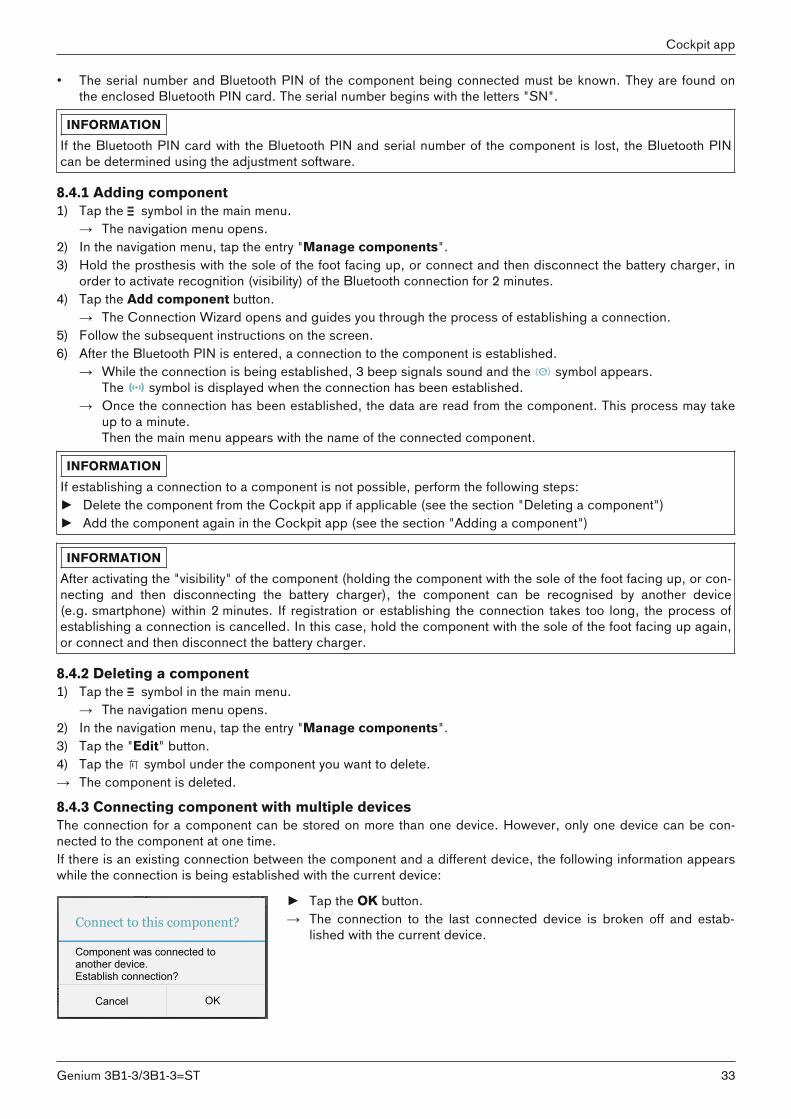
• The serial number and Bluetooth PIN of the component being connected must be known. They are found onthe enclosed Bluetooth PIN card. The serial number begins with the letters "SN".
INFORMATIONIf the Bluetooth PIN card with the Bluetooth PIN and serial number of the component is lost, the Bluetooth PINcan be determined using the adjustment software.
8.4.1 Adding component1) Tap the symbol in the main menu.
→ The navigation menu opens.2) In the navigation menu, tap the entry "Manage components".3) Hold the prosthesis with the sole of the foot facing up, or connect and then disconnect the battery charger, in
order to activate recognition (visibility) of the Bluetooth connection for 2 minutes. 4) Tap the Add component button.
→ The Connection Wizard opens and guides you through the process of establishing a connection. 5) Follow the subsequent instructions on the screen.6) After the Bluetooth PIN is entered, a connection to the component is established.
→ While the connection is being established, 3 beep signals sound and the symbol appears.The symbol is displayed when the connection has been established.
→ Once the connection has been established, the data are read from the component. This process may takeup to a minute.Then the main menu appears with the name of the connected component.
INFORMATIONIf establishing a connection to a component is not possible, perform the following steps:► Delete the component from the Cockpit app if applicable (see the section "Deleting a component")► Add the component again in the Cockpit app (see the section "Adding a component")
INFORMATIONAfter activating the "visibility" of the component (holding the component with the sole of the foot facing up, or connecting and then disconnecting the battery charger), the component can be recognised by another device(e.g. smartphone) within 2 minutes. If registration or establishing the connection takes too long, the process ofestablishing a connection is cancelled. In this case, hold the component with the sole of the foot facing up again,or connect and then disconnect the battery charger.
8.4.2 Deleting a component1) Tap the symbol in the main menu.
→ The navigation menu opens.2) In the navigation menu, tap the entry "Manage components".3) Tap the "Edit" button.4) Tap the symbol under the component you want to delete.→ The component is deleted.
8.4.3 Connecting component with multiple devicesThe connection for a component can be stored on more than one device. However, only one device can be connected to the component at one time. If there is an existing connection between the component and a different device, the following information appearswhile the connection is being established with the current device:
Connect to this component?
Cancel OK
Component was connected to another device. Establish connection?
► Tap the OK button.→ The connection to the last connected device is broken off and estab
lished with the current device.
33Genium 3B1-3/3B1-3=ST
Cockpit app

9 Use9.1 Movement patterns in basic mode (mode 1)9.1.1 Standing
Knee control through high hydraulic resistance and static alignment.A stance function can be enabled using the adjustment software. Please see the followingsection for further information on the stance function.
9.1.1.1 Stance function
INFORMATIONTo use this function, it needs to be enabled in the adjustment software. It also has to be activated using the Cockpit app (see Page 38).
The stance function (standing mode) is a functional supplement to the basic mode (mode 1). This function makes iteasier, for example, to stand on an inclined surface for a longer time. The joint is fixed in the flexion direction.This function must be enabled in the adjustment software. Once the function is enabled, you can also choosebetween an intuitive and a conscious lock.
Intuitive locking of the jointThe intuitive stance function recognises any situation that puts strain on the prosthesis in the flexion direction butwhere flexion is not permitted. Examples of this include standing on uneven or sloping surfaces. The knee joint isalways locked in the flexion direction when the prosthetic leg is not fully extended, under some amount of load andat rest. Upon forward or backward rollover or extension, the level of resistance is immediately reduced to stancephase resistance again.The knee joint is not locked when the above conditions are met and a sitting position is assumed (for example whiledriving).
Deliberate locking of the joint1) Assume the desired knee angle.2) Do not remove the entire load from the prosthesis.3) Do not change the knee angle for a brief period (1/8 second). This time period prevents unintentional activation
of the standing function. → The blocked joint can now be fully loaded in the flexion direction.
Deliberate unlocking of the joint► By deliberately extending or unloading the knee joint, is it unlocked again.
9.1.2 WalkingInitial attempts at walking with the prosthesis always require the instruction of trained, qualified personnel.The hydraulics stabilise the knee joint in the stance phase and release the knee joint in theswing phase so that the leg can swing forward freely.Switching to the swing phase requires that the prosthesis roll over to the front out of thestride position.
34
Use
Genium 3B1-3/3B1-3=ST
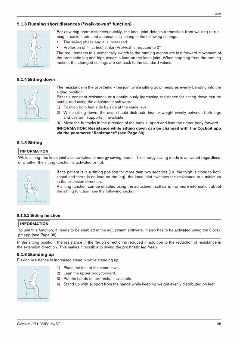
9.1.3 Running short distances ("walk-to-run" function)For covering short distances quickly, the knee joint detects a transition from walking to running in basic mode and automatically changes the following settings: • The swing phase angle is increased • Preflexion of 4° at heel strike (PreFlex) is reduced to 0°The requirements to automatically switch to the running motion are fast forward movement ofthe prosthetic leg and high dynamic load on the knee joint. When stopping from the runningmotion, the changed settings are set back to the standard values.
9.1.4 Sitting downThe resistance in the prosthetic knee joint while sitting down ensures evenly bending into thesitting position.Either a constant resistance or a continuously increasing resistance for sitting down can beconfigured using the adjustment software.1) Position both feet side by side at the same level.2) While sitting down, the user should distribute his/her weight evenly between both legs
and use arm supports, if available.3) Move the buttocks in the direction of the back support and lean the upper body forward.INFORMATION: Resistance while sitting down can be changed with the Cockpit appvia the parameter "Resistance" (see Page 38).
9.1.5 Sitting
INFORMATIONWhile sitting, the knee joint also switches to energy saving mode. This energy saving mode is activated regardlessof whether the sitting function is activated or not.
If the patient is in a sitting position for more than two seconds (i.e. the thigh is close to horizontal and there is no load on the leg), the knee joint switches the resistance to a minimumin the extension direction.A sitting function can be enabled using the adjustment software. For more information aboutthe sitting function, see the following section.
9.1.5.1 Sitting function
INFORMATIONTo use this function, it needs to be enabled in the adjustment software. It also has to be activated using the Cockpit app (see Page 38).
In the sitting position, the resistance in the flexion direction is reduced in addition to the reduction of resistance inthe extension direction. This makes it possible to swing the prosthetic leg freely.
9.1.6 Standing upFlexion resistance is increased steadily while standing up.
1) Place the feet at the same level.2) Lean the upper body forward.3) Put the hands on armrests, if available.4) Stand up with support from the hands while keeping weight evenly distributed on feet.
35Genium 3B1-3/3B1-3=ST
Use
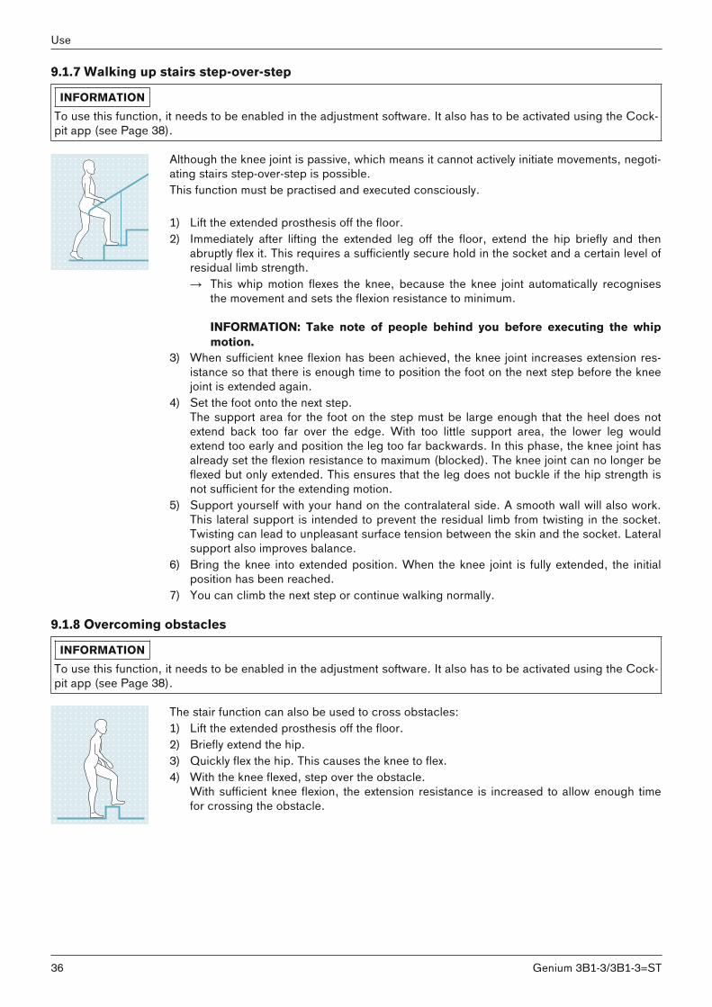
9.1.7 Walking up stairs step-over-step
INFORMATIONTo use this function, it needs to be enabled in the adjustment software. It also has to be activated using the Cockpit app (see Page 38).
Although the knee joint is passive, which means it cannot actively initiate movements, negotiating stairs step-over-step is possible.This function must be practised and executed consciously.
1) Lift the extended prosthesis off the floor. 2) Immediately after lifting the extended leg off the floor, extend the hip briefly and then
abruptly flex it. This requires a sufficiently secure hold in the socket and a certain level ofresidual limb strength. → This whip motion flexes the knee, because the knee joint automatically recognises
the movement and sets the flexion resistance to minimum.
INFORMATION: Take note of people behind you before executing the whipmotion.
3) When sufficient knee flexion has been achieved, the knee joint increases extension resistance so that there is enough time to position the foot on the next step before the kneejoint is extended again.
4) Set the foot onto the next step.The support area for the foot on the step must be large enough that the heel does notextend back too far over the edge. With too little support area, the lower leg wouldextend too early and position the leg too far backwards. In this phase, the knee joint hasalready set the flexion resistance to maximum (blocked). The knee joint can no longer beflexed but only extended. This ensures that the leg does not buckle if the hip strength isnot sufficient for the extending motion.
5) Support yourself with your hand on the contralateral side. A smooth wall will also work.This lateral support is intended to prevent the residual limb from twisting in the socket.Twisting can lead to unpleasant surface tension between the skin and the socket. Lateralsupport also improves balance.
6) Bring the knee into extended position. When the knee joint is fully extended, the initialposition has been reached.
7) You can climb the next step or continue walking normally.
9.1.8 Overcoming obstacles
INFORMATIONTo use this function, it needs to be enabled in the adjustment software. It also has to be activated using the Cockpit app (see Page 38).
The stair function can also be used to cross obstacles:1) Lift the extended prosthesis off the floor.2) Briefly extend the hip.3) Quickly flex the hip. This causes the knee to flex.4) With the knee flexed, step over the obstacle.
With sufficient knee flexion, the extension resistance is increased to allow enough timefor crossing the obstacle.
36
Use
Genium 3B1-3/3B1-3=ST
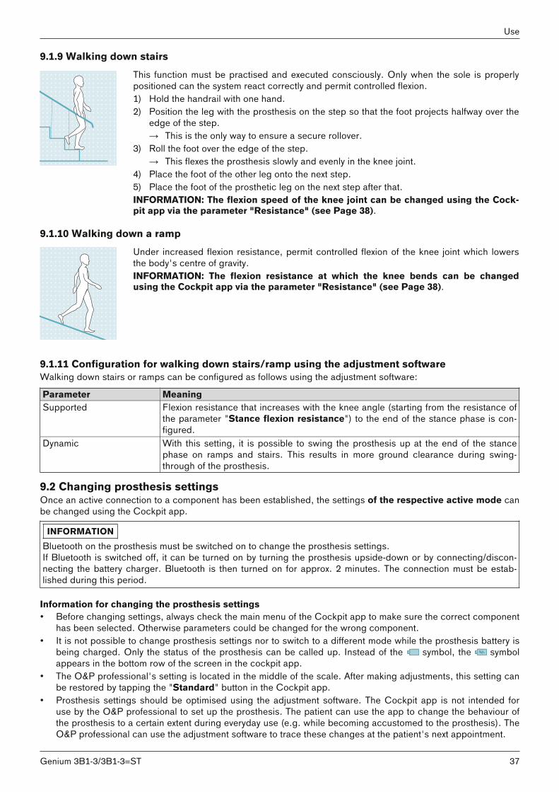
9.1.9 Walking down stairsThis function must be practised and executed consciously. Only when the sole is properlypositioned can the system react correctly and permit controlled flexion.1) Hold the handrail with one hand.2) Position the leg with the prosthesis on the step so that the foot projects halfway over the
edge of the step.→ This is the only way to ensure a secure rollover.
3) Roll the foot over the edge of the step.→ This flexes the prosthesis slowly and evenly in the knee joint.
4) Place the foot of the other leg onto the next step.5) Place the foot of the prosthetic leg on the next step after that.INFORMATION: The flexion speed of the knee joint can be changed using the Cockpit app via the parameter "Resistance" (see Page 38).
9.1.10 Walking down a rampUnder increased flexion resistance, permit controlled flexion of the knee joint which lowersthe body's centre of gravity.INFORMATION: The flexion resistance at which the knee bends can be changedusing the Cockpit app via the parameter "Resistance" (see Page 38).
9.1.11 Configuration for walking down stairs/ramp using the adjustment softwareWalking down stairs or ramps can be configured as follows using the adjustment software:
Parameter MeaningSupported Flexion resistance that increases with the knee angle (starting from the resistance of
the parameter "Stance flexion resistance") to the end of the stance phase is configured.
Dynamic With this setting, it is possible to swing the prosthesis up at the end of the stancephase on ramps and stairs. This results in more ground clearance during swing-through of the prosthesis.
9.2 Changing prosthesis settingsOnce an active connection to a component has been established, the settings of the respective active mode canbe changed using the Cockpit app.
INFORMATIONBluetooth on the prosthesis must be switched on to change the prosthesis settings.If Bluetooth is switched off, it can be turned on by turning the prosthesis upside-down or by connecting/disconnecting the battery charger. Bluetooth is then turned on for approx. 2 minutes. The connection must be established during this period.
Information for changing the prosthesis settings• Before changing settings, always check the main menu of the Cockpit app to make sure the correct component
has been selected. Otherwise parameters could be changed for the wrong component.• It is not possible to change prosthesis settings nor to switch to a different mode while the prosthesis battery is
being charged. Only the status of the prosthesis can be called up. Instead of the symbol, the symbolappears in the bottom row of the screen in the cockpit app.
• The O&P professional's setting is located in the middle of the scale. After making adjustments, this setting canbe restored by tapping the "Standard" button in the Cockpit app.
• Prosthesis settings should be optimised using the adjustment software. The Cockpit app is not intended foruse by the O&P professional to set up the prosthesis. The patient can use the app to change the behaviour ofthe prosthesis to a certain extent during everyday use (e.g. while becoming accustomed to the prosthesis). TheO&P professional can use the adjustment software to trace these changes at the patient's next appointment.
37Genium 3B1-3/3B1-3=ST
Use

• If the settings of a MyMode are to be modified, one must first switch to this MyMode.
9.2.1 Changing the prosthesis setting using the cockpit app
2. Golf
change
MyModes
Functions
Settings
Status
General
Manage components
Imprint/Info
Product
1) Once the component is connected and in the desired mode, tap the symbol in the main menu.
→ The navigation menu opens.2) Tap the menu entry "Settings".
→ A list appears with the parameters for the currently selected mode.3) Change the setting of the desired parameter by tapping the "<", ">"
symbols.INFORMATION: The prosthetist's setting is marked and, after thesetting has been changed, can be restored by tapping the "Standard" button.
9.2.2 Overview of adjustment parameters in basic mode
INFORMATIONWhen mute mode (silent mode) is activated, no beep and vibration signals are generated.
The parameters in basic mode describe the dynamic behaviour of the prosthesis in a normal gait cycle. These parameters act as basic settings for automatically adjusting the damping behaviour to the current motion situation (e.g.ramps, slow walking speed, etc.).The stance function, sitting function and/or stairs and obstacles function can also be activated/deactivated. Furtherinformation on the stance function (see Page 34), sitting function (see Page 35), stairs and obstacles function (seePage 36).
The following parameters can be modified:
Parameter Adjustment software range
Setting range,app
Meaning
Resistance 120 – 180 +/- 10 Resistance against flexion motion e.g. whenwalking down stairs or when sitting down
Angle 55° – 70° +/- 3° Maximum flexion angle in the swing phaseStance function Deactivated
Activated0 - deactivated1 - activated
Activation/deactivation of the stance function.For switching with the Cockpit app, this function has to be activated in the adjustmentsoftware. Further information (see Page 34).
Sitting function DeactivatedActivated
0 - deactivated1 - activated
Activation/deactivation of the sitting function.For switching with the Cockpit app, this function has to be activated in the adjustmentsoftware. Further information (see Page 35).
Stair Function DeactivatedActivated
0 - deactivated1 - activated
Activating/deactivating the stair and obstaclefunction. For switching with the Cockpit app,this function has to be activated in the adjustment software. Further information (seePage 36).
38
Use
Genium 3B1-3/3B1-3=ST
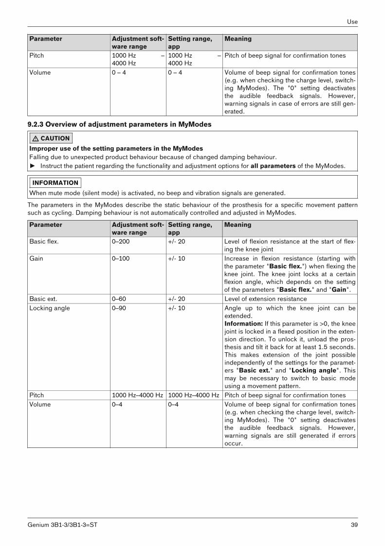
Parameter Adjustment software range
Setting range,app
Meaning
Pitch 1000 Hz –4000 Hz
1000 Hz –4000 Hz
Pitch of beep signal for confirmation tones
Volume 0 – 4 0 – 4 Volume of beep signal for confirmation tones(e.g. when checking the charge level, switching MyModes). The "0" setting deactivatesthe audible feedback signals. However,warning signals in case of errors are still generated.
9.2.3 Overview of adjustment parameters in MyModes
CAUTIONImproper use of the setting parameters in the MyModesFalling due to unexpected product behaviour because of changed damping behaviour.► Instruct the patient regarding the functionality and adjustment options for all parameters of the MyModes.
INFORMATIONWhen mute mode (silent mode) is activated, no beep and vibration signals are generated.
The parameters in the MyModes describe the static behaviour of the prosthesis for a specific movement patternsuch as cycling. Damping behaviour is not automatically controlled and adjusted in MyModes.
Parameter Adjustment software range
Setting range,app
Meaning
Basic flex. 0–200 +/- 20 Level of flexion resistance at the start of flexing the knee joint
Gain 0–100 +/- 10 Increase in flexion resistance (starting withthe parameter "Basic flex.") when flexing theknee joint. The knee joint locks at a certainflexion angle, which depends on the settingof the parameters "Basic flex." and "Gain".
Basic ext. 0–60 +/- 20 Level of extension resistanceLocking angle 0–90 +/- 10 Angle up to which the knee joint can be
extended.Information: If this parameter is >0, the kneejoint is locked in a flexed position in the extension direction. To unlock it, unload the prosthesis and tilt it back for at least 1.5 seconds.This makes extension of the joint possibleindependently of the settings for the parameters "Basic ext." and "Locking angle". Thismay be necessary to switch to basic modeusing a movement pattern.
Pitch 1000 Hz–4000 Hz 1000 Hz–4000 Hz Pitch of beep signal for confirmation tonesVolume 0–4 0–4 Volume of beep signal for confirmation tones
(e.g. when checking the charge level, switching MyModes). The "0" setting deactivatesthe audible feedback signals. However,warning signals are still generated if errorsoccur.
39Genium 3B1-3/3B1-3=ST
Use

9.3 Turning Bluetooth on the prosthesis on/offINFORMATION
Bluetooth on the prosthesis must be turned on in order to use the Cockpit app.If Bluetooth is switched off, it can be turned on by turning the prosthesis upside-down (function only available inbasic mode) or by connecting/disconnecting the battery charger. Bluetooth is then turned on for approx. 2minutes. During this time, the app must be started and used to establish a connection. If required, Bluetooth onthe prosthesis can be switched on permanently afterwards (see Page 40).
INFORMATIONBasic mode (mode 1) has to be active to turn off Bluetooth. If a MyMode is activated, one has to switch to basicmode to turn off Bluetooth.
9.3.1 Switching Bluetooth off/on using the cockpit app
Switching off Bluetooth1) When the component is connected, tap the symbol in the main menu.
→ The navigation menu opens.2) In the navigation menu, tap the entry "Functions".3) Tap the entry "Deactivate Bluetooth".4) Follow the on-screen instructions.
Switching on Bluetooth1) Turn the component over or connect/disconnect the battery charger.
→ Bluetooth is switched on for approx. 2 minutes. During this time, the app must be started in order to establish a connection to the component.
2) Follow the on-screen instructions.→ If Bluetooth is switched on, the symbol appears on the screen.
9.4 Querying the prosthesis status9.4.1 Query status through cockpit app1) When the component is connected, tap the symbol in the main menu.2) In the navigation menu, tap the entry "Status".
9.4.2 Status display in the cockpit appMenu option Description Possible actionsTrip Daily step counter (steps with the
prosthesis side)Reset the counter by tapping the"Reset" button.
Step Total step counter (steps with theprosthesis side)
For informational purposes only
Service Display of the next maintenance date For informational purposes onlyBatt. Current prosthesis charge level, as a
percentageFor informational purposes only
Stb/Act: 58/29 Estimated remaining operating timeof prosthesis in hours. Rest mode(Stb) e.g. 58 hours, active use (Act)e.g. 29 hours
For informational purposes only
9.5 Mute mode (silent mode)Activating mute mode (silent mode) turns off the audible feedback signals and the vibration signals. However,warnings in case of component errors are still generated (see Page 52).Mute mode can be activated/deactivated using the Cockpit app.
INFORMATIONConnecting the battery charger automatically deactivates mute mode again.
9.5.1 Turning mute mode on/off using the Cockpit app1) When the component is connected, tap the symbol in the main menu.
40
Use
Genium 3B1-3/3B1-3=ST
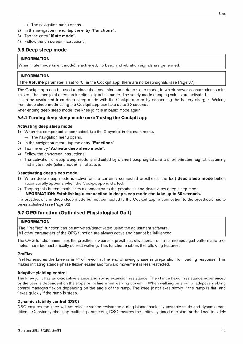
→ The navigation menu opens.2) In the navigation menu, tap the entry "Functions".3) Tap the entry "Mute mode".4) Follow the on-screen instructions.
9.6 Deep sleep modeINFORMATION
When mute mode (silent mode) is activated, no beep and vibration signals are generated.
INFORMATIONIf the Volume parameter is set to '0' in the Cockpit app, there are no beep signals (see Page 37).
The Cockpit app can be used to place the knee joint into a deep sleep mode, in which power consumption is minimised. The knee joint offers no functionality in this mode. The safety mode damping values are activated.It can be awakened from deep sleep mode with the Cockpit app or by connecting the battery charger. Wakingfrom deep sleep mode using the Cockpit app can take up to 30 seconds.After ending deep sleep mode, the knee joint is in basic mode again.
9.6.1 Turning deep sleep mode on/off using the Cockpit app
Activating deep sleep mode1) When the component is connected, tap the symbol in the main menu.
→ The navigation menu opens.2) In the navigation menu, tap the entry "Functions".3) Tap the entry "Activate deep sleep mode".4) Follow the on-screen instructions.→ The activation of deep sleep mode is indicated by a short beep signal and a short vibration signal, assuming
that mute mode (silent mode) is not active.
Deactivating deep sleep mode1) When deep sleep mode is active for the currently connected prosthesis, the Exit deep sleep mode button
automatically appears when the Cockpit app is started.2) Tapping this button establishes a connection to the prosthesis and deactivates deep sleep mode.
INFORMATION: Establishing a connection in deep sleep mode can take up to 30 seconds.If a prosthesis is in deep sleep mode but not connected to the Cockpit app, a connection to the prosthesis has tobe established (see Page 32).
9.7 OPG function (Optimised Physiological Gait)INFORMATION
The "PreFlex" function can be activated/deactivated using the adjustment software.All other parameters of the OPG function are always active and cannot be influenced.
The OPG function minimises the prosthesis wearer's prosthetic deviations from a harmonious gait pattern and promotes more biomechanically correct walking. This function enables the following features:
PreFlexPreFlex ensures the knee is in 4° of flexion at the end of swing phase in preparation for loading response. Thismakes initiating stance phase flexion easier and forward movement is less restricted.
Adaptive yielding controlThe knee joint has auto-adaptive stance and swing extension resistance. The stance flexion resistance experiencedby the user is dependent on the slope or incline when walking downhill. When walking on a ramp, adaptive yieldingcontrol manages flexion depending on the angle of the ramp. The knee joint flexes slowly if the ramp is flat, andflexes quickly if the ramp is steep.
Dynamic stability control (DSC)DSC ensures the knee will not release stance resistance during biomechanically unstable static and dynamic conditions. Constantly checking multiple parameters, DSC ensures the optimally timed decision for the knee to safely
41Genium 3B1-3/3B1-3=ST
Use
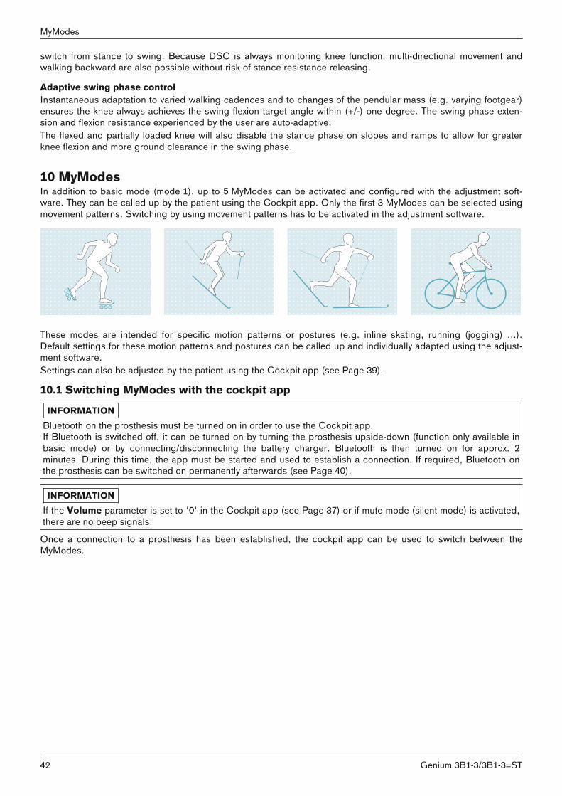
switch from stance to swing. Because DSC is always monitoring knee function, multi-directional movement andwalking backward are also possible without risk of stance resistance releasing.
Adaptive swing phase controlInstantaneous adaptation to varied walking cadences and to changes of the pendular mass (e.g. varying footgear)ensures the knee always achieves the swing flexion target angle within (+/-) one degree. The swing phase extension and flexion resistance experienced by the user are auto-adaptive.The flexed and partially loaded knee will also disable the stance phase on slopes and ramps to allow for greaterknee flexion and more ground clearance in the swing phase.
10 MyModesIn addition to basic mode (mode 1), up to 5 MyModes can be activated and configured with the adjustment software. They can be called up by the patient using the Cockpit app. Only the first 3 MyModes can be selected usingmovement patterns. Switching by using movement patterns has to be activated in the adjustment software.
These modes are intended for specific motion patterns or postures (e.g. inline skating, running (jogging) ...).Default settings for these motion patterns and postures can be called up and individually adapted using the adjustment software.Settings can also be adjusted by the patient using the Cockpit app (see Page 39).
10.1 Switching MyModes with the cockpit appINFORMATION
Bluetooth on the prosthesis must be turned on in order to use the Cockpit app.If Bluetooth is switched off, it can be turned on by turning the prosthesis upside-down (function only available inbasic mode) or by connecting/disconnecting the battery charger. Bluetooth is then turned on for approx. 2minutes. During this time, the app must be started and used to establish a connection. If required, Bluetooth onthe prosthesis can be switched on permanently afterwards (see Page 40).
INFORMATIONIf the Volume parameter is set to '0' in the Cockpit app (see Page 37) or if mute mode (silent mode) is activated,there are no beep signals.
Once a connection to a prosthesis has been established, the cockpit app can be used to switch between theMyModes.
42
MyModes
Genium 3B1-3/3B1-3=ST
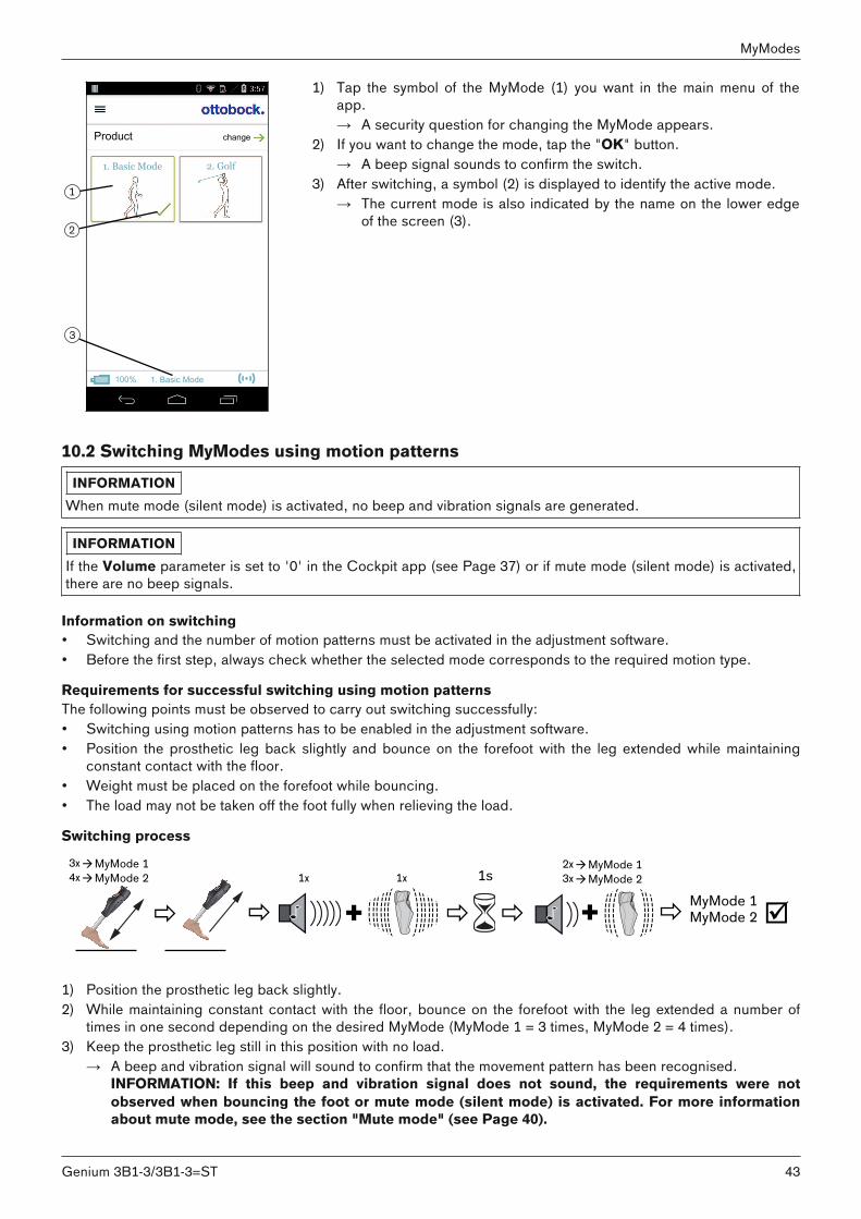
1
2
3
Product change
2. Golf
1. Basic Mode
1. Basic Mode
100%
1) Tap the symbol of the MyMode (1) you want in the main menu of theapp.→ A security question for changing the MyMode appears.
2) If you want to change the mode, tap the "OK" button.→ A beep signal sounds to confirm the switch.
3) After switching, a symbol (2) is displayed to identify the active mode.→ The current mode is also indicated by the name on the lower edge
of the screen (3).
10.2 Switching MyModes using motion patternsINFORMATION
When mute mode (silent mode) is activated, no beep and vibration signals are generated.
INFORMATIONIf the Volume parameter is set to '0' in the Cockpit app (see Page 37) or if mute mode (silent mode) is activated,there are no beep signals.
Information on switching• Switching and the number of motion patterns must be activated in the adjustment software.• Before the first step, always check whether the selected mode corresponds to the required motion type.
Requirements for successful switching using motion patternsThe following points must be observed to carry out switching successfully:• Switching using motion patterns has to be enabled in the adjustment software.• Position the prosthetic leg back slightly and bounce on the forefoot with the leg extended while maintaining
constant contact with the floor. • Weight must be placed on the forefoot while bouncing.• The load may not be taken off the foot fully when relieving the load.
Switching process
+ + MyMode 1 þðð ð ð ð MyMode 2
3x1sàMyMode 1
4xàMyMode 22xàMyMode 13xàMyMode 21x 1x
1) Position the prosthetic leg back slightly.2) While maintaining constant contact with the floor, bounce on the forefoot with the leg extended a number of
times in one second depending on the desired MyMode (MyMode 1 = 3 times, MyMode 2 = 4 times).3) Keep the prosthetic leg still in this position with no load.
→ A beep and vibration signal will sound to confirm that the movement pattern has been recognised.INFORMATION: If this beep and vibration signal does not sound, the requirements were notobserved when bouncing the foot or mute mode (silent mode) is activated. For more informationabout mute mode, see the section "Mute mode" (see Page 40).
43Genium 3B1-3/3B1-3=ST
MyModes

4) After the beep and vibration signal sounds, keep the prosthetic leg extended and still for 1 second. → A confirmation signal will sound to indicate that the prosthesis has successfully switched to the corresponding
MyMode (2 times = MyMode 1, 3 times = MyMode 2).INFORMATION: If this confirmation signal does not sound, the leg with the prosthesis was not correctly kept still or mute mode (silent mode) is activated. Repeat the process to correctly switch to therequired mode. For more information about mute mode, see the section "Mute mode" (see Page 40).
10.3 Switching from a MyMode back to basic modeInformation on switching• Regardless of the configuration of additional MyModes in the adjustment software, it is always possible to
switch back to basic mode (mode 1) with a motion pattern.• It is always possible to switch back to basic mode (mode 1) by connecting/disconnecting the battery charger.• Before the first step, always check whether the selected mode corresponds to the required motion type.
Requirements for successful switching using motion patternsThe following points must be observed to carry out switching successfully:• Position the prosthetic leg back slightly and bounce on the forefoot with the leg extended while maintaining
constant contact with the floor. • Weight must be placed on the forefoot while bouncing.• The load may not be taken off the foot fully when relieving the load.
Switching process
+ +ðð ð ð ð≥3x 1s 1x 1x1x 1x
þBasic mode
þ1) Position the prosthetic leg back slightly.2) While maintaining constant contact with the floor and with the leg extended, bounce on the forefoot at 3 times
or more.3) Keep the prosthetic leg still in this position with no load.
→ A beep and vibration signal will sound to confirm that the movement pattern has been recognised.INFORMATION: If this beep and vibration signal does not sound, the requirements were notobserved when bouncing the foot or mute mode (silent mode) is activated. For more informationabout mute mode, see the section "Mute mode" (see Page 40).
4) After the beep and vibration signal sounds, keep the prosthetic leg extended and still for 1 second. → A confirmation signal will sound to indicate that the prosthesis has successfully switched over to basic mode.
INFORMATION: If this confirmation signal does not sound, the leg with the prosthesis was not correctly kept still or mute mode (silent mode) is activated. Repeat the process to correctly switch to therequired mode. For more information about mute mode, see the section "Mute mode" (see Page 40).
11 Additional operating states (modes)11.1 Empty battery modeBeeps and vibration signals are emitted if the available battery charge level is 5% (see Page 52). During this time,damping settings are set to their safety mode values. This may be low or high depending on the setting in theadjustment software. The prosthesis is then switched off. You can switch back to basic mode (mode 1) from emptybattery mode by charging the product.
11.2 Mode for charging the prosthesisThe product is non-functional during charging.The product is set to safety mode damping. This may be low or high depending on the setting in the adjustmentsoftware.
44
Additional operating states (modes)
Genium 3B1-3/3B1-3=ST
11.3 Safety modeThe product automatically switches to safety mode if a critical system fault occurs (e.g. failure of a sensor signal).Safety mode remains in effect until the error has been rectified. The switch to safety mode is indicated by beeps and vibration signals immediately prior to switching (see Page 52).Safety mode can be disabled by connecting and disconnecting the battery charger. If the product switches intosafety mode again, this means a permanent error exists. The product must be inspected by an authorised OttobockService Centre.Depending on the type and severity of the error, different remaining functionality is offered in safety mode. Thismakes limited walking possible for the user depending on the type of error.
The following functionality is available:• Moderate error: Continuous stance phase flexion resistance is set, with the ability to initiate the swing phase.
The swing phase control and stance phase extension resistance may be available or not depending on the typeof error.
• Severe error: Safety mode flexion resistance is configured. This may be low or high depending on the settingin the adjustment software. Depending on the type of error, the product may also be blocked entirely in the flexion direction.
The following functions are deactivated in safety mode:• OPG function• Stairs and obstacles function• Stance function• Sitting function
11.4 Overheating modeINFORMATION
When mute mode (silent mode) is activated, no beep and vibration signals are generated.
When the hydraulic unit overheats due to uninterrupted, increased activity (e.g. extended walking downhill), damping is increased along with the rising temperature in order to counteract the overheating. When the hydraulic unitcools down, the product switches back to the damping settings that existed before the overheating mode.Overheating mode is not activated in the MyModes.Overheating mode is indicated by a long vibration every 5 seconds.
The following functions are deactivated in overheating mode:• Sitting function• Display of the battery charge level without additional equipment• Switching to a MyMode
12 Storage and bleedingAir may accumulate in the hydraulic unit if the product is stored for longer periods and not in an upright position.This is noticeable through sounds and irregular damping behaviour.The automatic bleeding mechanism ensures that all functions of the product are again intact after approximately 10- 20 steps.
Storage• When storing the knee joint, press the top of the knee to the flexion stop.• Avoid extended disuse of the product (use the product regularly).
13 Cleaning1) Clean the product with a damp cloth (fresh water) when needed. 2) Dry the product with a lint-free cloth and allow it to air dry fully.
45Genium 3B1-3/3B1-3=ST
Storage and bleeding

14 MaintenanceINFORMATION
This component was tested for three million load cycles in accordance with ISO 10328.Depending on the activity level, this corresponds to a service life of three to five years.The duration of use can be individually extended depending on the intensity of use by performing regular serviceinspections.
Regular service inspections (maintenance) are mandatory in the interest of the patient's safety and in order to maintain operating reliability and protect the warranty. These service inspections include an inspection of the sensorsand replacement of wear and tear parts.If maintenance is due, this is indicated after the service interval has expired by three brief beep and vibration signals after disconnecting the battery charger. Further information is available upon request by contacting the authorised Ottobock Service Center responsible for your country.To have a service inspection carried out, please send the product with mounted tube adapter as well as the batterycharger and power supply unit to an authorised Ottobock Service Centre.
INFORMATIONBefore shipping the knee joint, the top of the knee joint should be angled to avoid air getting into the hydraulicsystem during transportation.
14.1 Identification of the product by the Service CenterThe product may have been identified by an authorised Ottobock Service Center:
Factory settingThe patient-specific product settings have been reset to the state at delivery (factory setting).
User settingThe settings already configured using the adjustment software were not changed.
CAUTIONUse of the prosthesis with incorrect setting dataFalling due to unexpected prosthesis behaviour caused by triggering the swing phase at the wrong time.► The prosthesis settings (parameters) have to be checked using the corresponding adjustment software and
changed as needed.
15 Legal informationAll legal conditions are subject to the respective national laws of the country of use and may vary accordingly.
15.1 LiabilityThe manufacturer will only assume liability if the product is used in accordance with the descriptions and instructions provided in this document. The manufacturer will not assume liability for damage caused by disregarding theinformation in this document, particularly due to improper use or unauthorised modification of the product.
15.2 TrademarksAll product names mentioned in this document are subject without restriction to the respective applicable trademark laws and are the property of the respective owners.All brands, trade names or company names may be registered trademarks and are the property of the respectiveowners.Should trademarks used in this document fail to be explicitly identified as such, this does not justify the conclusionthat the denotation in question is free of third-party rights.
15.3 CE conformityThis product meets the requirements of the European Directive 93/42/EEC for medical devices. This product hasbeen classified as a class I device according to the classification criteria outlined in Annex IX of the directive. The
46
Maintenance
Genium 3B1-3/3B1-3=ST

declaration of conformity was therefore created by the manufacturer with sole responsibility according to Annex VIIof the directive.Hereby, Ottobock Healthcare Products GmbH declares that the product is in compliance with Directive2014/53/EU. The full text of the EU declaration of conformity is available at the following internet address:www.ottobock.com/conformityThe product meets the requirements under the RoHS Directive 2011/65/EU of the European Parliament and of theCouncil of 8 June 2011 on the restriction of the use of certain hazardous substances in electrical and electronicequipment.
15.4 Local Legal InformationLegal information that applies exclusively to specific countries is written in the official language of the respectivecountry of use in this chapter.
This device complies with part 15 of the FCC Rules. Operation is subject to the following two conditions:1) This device may not cause harmful interference, and2) This device must accept any interference received, including interference that may cause undesired operation.This equipment has been tested and found to comply with the limits for a Class B digital device, pursuant to part15 of the FCC Rules. These limits are designed to provide reasonable protection against harmful interference in aresidential installation. This equipment generates uses and can radiate radio frequency energy and, if not installedand used in accordance with the instructions, may cause harmful interference to radio communications. However,there is no guarantee that interference will not occur in a particular installation. If this equipment does cause harmful interference to radio or television reception, which can be determined by turning the equipment off and on, theuser is encouraged to try to correct the interference by one or more of the following measures:—Reorient or relocate the receiving antenna.—Increase the separation between the equipment and receiver.—Connect the equipment into an outlet on a circuit different from that to which the receiver is connected.—Consult the dealer or an experienced radio/ TV technician for help.Any changes or modifications not expressly approved by the party responsible for compliance could void the user’sauthority to operate the equipment.Caution: Exposure to Radio Frequency Radiation.This device must not be co-located or operating in conjunction with any other antenna or transmitter.Responsible party:Otto Bock Health Care, LP3820 West Great Lakes DriveSalt Lake City, Utah 84120-7205 USAPhone + 1-801-956-2400Fax + 1-801-956-2401
This device complies with RSS 210 of Industry Canada. Operation is subject to the following two conditions: (1) this device may not cause interference, and (2) this device must accept any interference, including interference that may cause undesired operation of thisdevice.
L’ utilisation de ce dispositif est autorisée seulement aux conditions suivantes: (1) il ne doit pas produire d’interference et (2) l’ utilisateur du dispositif doit étre prêt à accepter toute interference radioélectrique reçu, même si celle-ci estsusceptible de compromettre le fonctionnement du dispositif.Caution: Exposure to Radio Frequency Radiation.The installer of this radio equipment must ensure that the antenna is located or pointed such that it does not emitRF field in excess of Health Canada limits for the general population; consult Safety Code 6, obtainable fromHealth Canada’s websitehttp://www.hc-sc.gc.ca/rpb.
47Genium 3B1-3/3B1-3=ST
Legal information
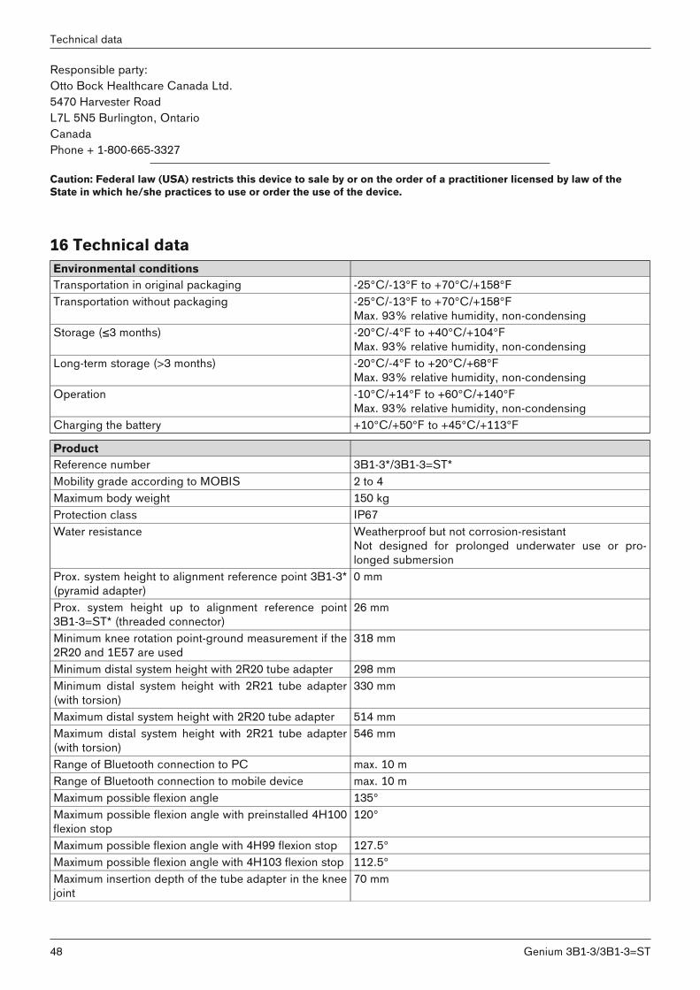
Responsible party:Otto Bock Healthcare Canada Ltd.5470 Harvester RoadL7L 5N5 Burlington, OntarioCanadaPhone + 1-800-665-3327
Caution: Federal law (USA) restricts this device to sale by or on the order of a practitioner licensed by law of theState in which he/she practices to use or order the use of the device.
16 Technical dataEnvironmental conditionsTransportation in original packaging -25°C/-13°F to +70°C/+158°FTransportation without packaging -25°C/-13°F to +70°C/+158°F
Max. 93% relative humidity, non-condensingStorage (≤3 months) -20°C/-4°F to +40°C/+104°F
Max. 93% relative humidity, non-condensingLong-term storage (>3 months) -20°C/-4°F to +20°C/+68°F
Max. 93% relative humidity, non-condensingOperation -10°C/+14°F to +60°C/+140°F
Max. 93% relative humidity, non-condensingCharging the battery +10°C/+50°F to +45°C/+113°F
ProductReference number 3B1-3*/3B1-3=ST*Mobility grade according to MOBIS 2 to 4Maximum body weight 150 kgProtection class IP67Water resistance Weatherproof but not corrosion-resistant
Not designed for prolonged underwater use or prolonged submersion
Prox. system height to alignment reference point 3B1-3*(pyramid adapter)
0 mm
Prox. system height up to alignment reference point3B1-3=ST* (threaded connector)
26 mm
Minimum knee rotation point-ground measurement if the2R20 and 1E57 are used
318 mm
Minimum distal system height with 2R20 tube adapter 298 mmMinimum distal system height with 2R21 tube adapter(with torsion)
330 mm
Maximum distal system height with 2R20 tube adapter 514 mmMaximum distal system height with 2R21 tube adapter(with torsion)
546 mm
Range of Bluetooth connection to PC max. 10 mRange of Bluetooth connection to mobile device max. 10 mMaximum possible flexion angle 135°Maximum possible flexion angle with preinstalled 4H100flexion stop
120°
Maximum possible flexion angle with 4H99 flexion stop 127.5°Maximum possible flexion angle with 4H103 flexion stop 112.5°Maximum insertion depth of the tube adapter in the kneejoint
70 mm
48
Technical data
Genium 3B1-3/3B1-3=ST
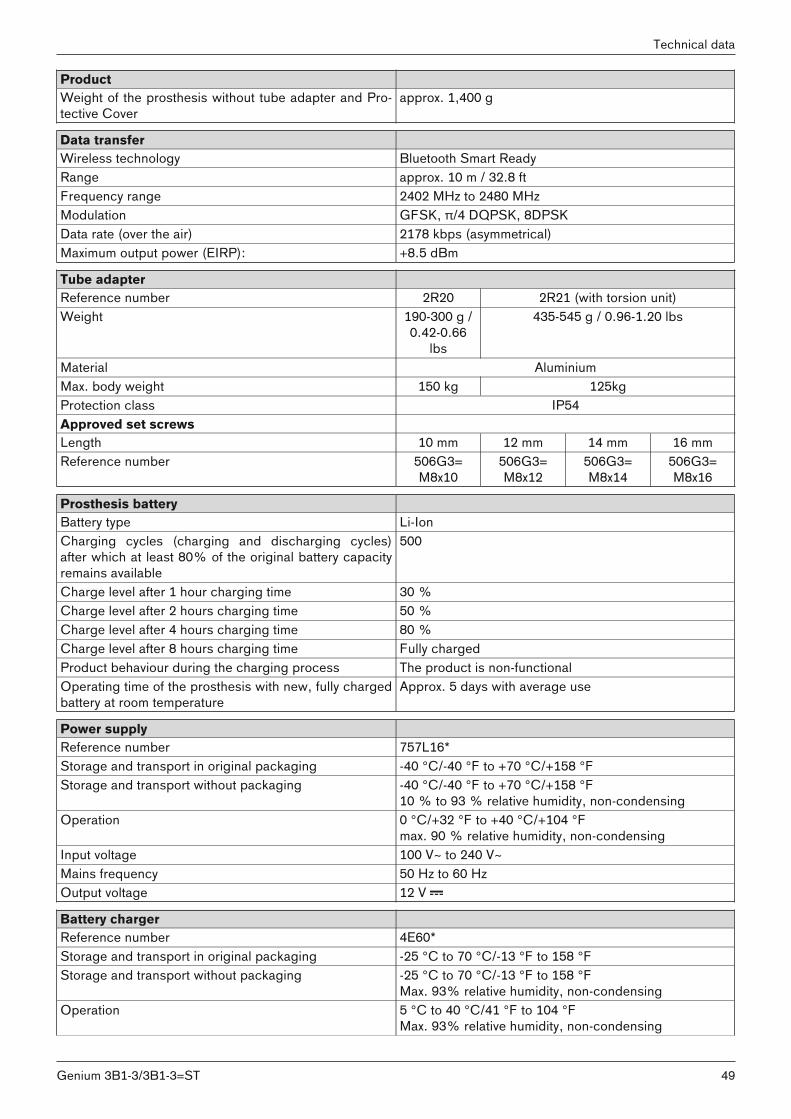
ProductWeight of the prosthesis without tube adapter and Protective Cover
approx. 1,400 g
Data transferWireless technology Bluetooth Smart ReadyRange approx. 10 m / 32.8 ftFrequency range 2402 MHz to 2480 MHzModulation GFSK, π/4 DQPSK, 8DPSKData rate (over the air) 2178 kbps (asymmetrical)Maximum output power (EIRP): +8.5 dBm
Tube adapterReference number 2R20 2R21 (with torsion unit)Weight 190-300 g /
0.42-0.66lbs
435-545 g / 0.96-1.20 lbs
Material AluminiumMax. body weight 150 kg 125kgProtection class IP54Approved set screwsLength 10 mm 12 mm 14 mm 16 mmReference number 506G3=
M8x10506G3=M8x12
506G3=M8x14
506G3=M8x16
Prosthesis batteryBattery type Li-IonCharging cycles (charging and discharging cycles)after which at least 80% of the original battery capacityremains available
500
Charge level after 1 hour charging time 30 %Charge level after 2 hours charging time 50 %Charge level after 4 hours charging time 80 %Charge level after 8 hours charging time Fully chargedProduct behaviour during the charging process The product is non-functionalOperating time of the prosthesis with new, fully chargedbattery at room temperature
Approx. 5 days with average use
Power supply Reference number 757L16*Storage and transport in original packaging -40 °C/-40 °F to +70 °C/+158 °FStorage and transport without packaging -40 °C/-40 °F to +70 °C/+158 °F
10 % to 93 % relative humidity, non-condensingOperation 0 °C/+32 °F to +40 °C/+104 °F
max. 90 % relative humidity, non-condensingInput voltage 100 V~ to 240 V~Mains frequency 50 Hz to 60 HzOutput voltage 12 V
Battery charger Reference number 4E60*Storage and transport in original packaging -25 °C to 70 °C/-13 °F to 158 °FStorage and transport without packaging -25 °C to 70 °C/-13 °F to 158 °F
Max. 93% relative humidity, non-condensingOperation 5 °C to 40 °C/41 °F to 104 °F
Max. 93% relative humidity, non-condensing
49Genium 3B1-3/3B1-3=ST
Technical data

Battery charger Protection rating IP40Input voltage 12 V
Cockpit app Reference number Cockpit 4X441-IOS=* / 4X441-Andr=V*Supported operating system iOS 9.3 / Android 4.0.3 or higherWebsite for download http://www.ottobock.com/cockpitapp
Torque values of the screw connectionsUsing a torque wrench, tighten the corresponding screws alternately in several cycles until the specified tighteningtorque is reached.
Screw connection Tightening torqueTube adapter on prosthetic foot 15 Nm / 133 lbf. In.Tube clamp of the knee joint 7 Nm / 62 lbf. In.Proximal prosthesis components with pyramid receiver 15 Nm / 133 lbf. In.Proximal prosthesis components with threaded connector
10 Nm / 89 lbf. In.
Flexion stop 0.6 Nm / 5 lbf. In.
17 Appendices17.1 Symbols Used
Legal manufacturer
Type BF applied part
Compliance with the requirements according to "FCC Part 15" (USA)
Compliance with the requirements under the "Radiocommunications Act" (AUS)
Non-ionising radiation
Protection against penetration of solid foreign objects with a diameter greater than 1 mm, no protection against water
Dustproof, protection against temporary submersion
In some jurisdictions it is not permissible to dispose of these products with unsorted householdwaste. Disposal that is not in accordance with the regulations of your country may have a detrimental impact on health and the environment. Please observe the instructions of your nationalauthority pertaining to return and collection.
The product's Bluetooth wireless module can establish a connection to devices with the following operating systems: iOS (iPhone, iPad, iPod,...) and Android
50
Appendices
Genium 3B1-3/3B1-3=ST
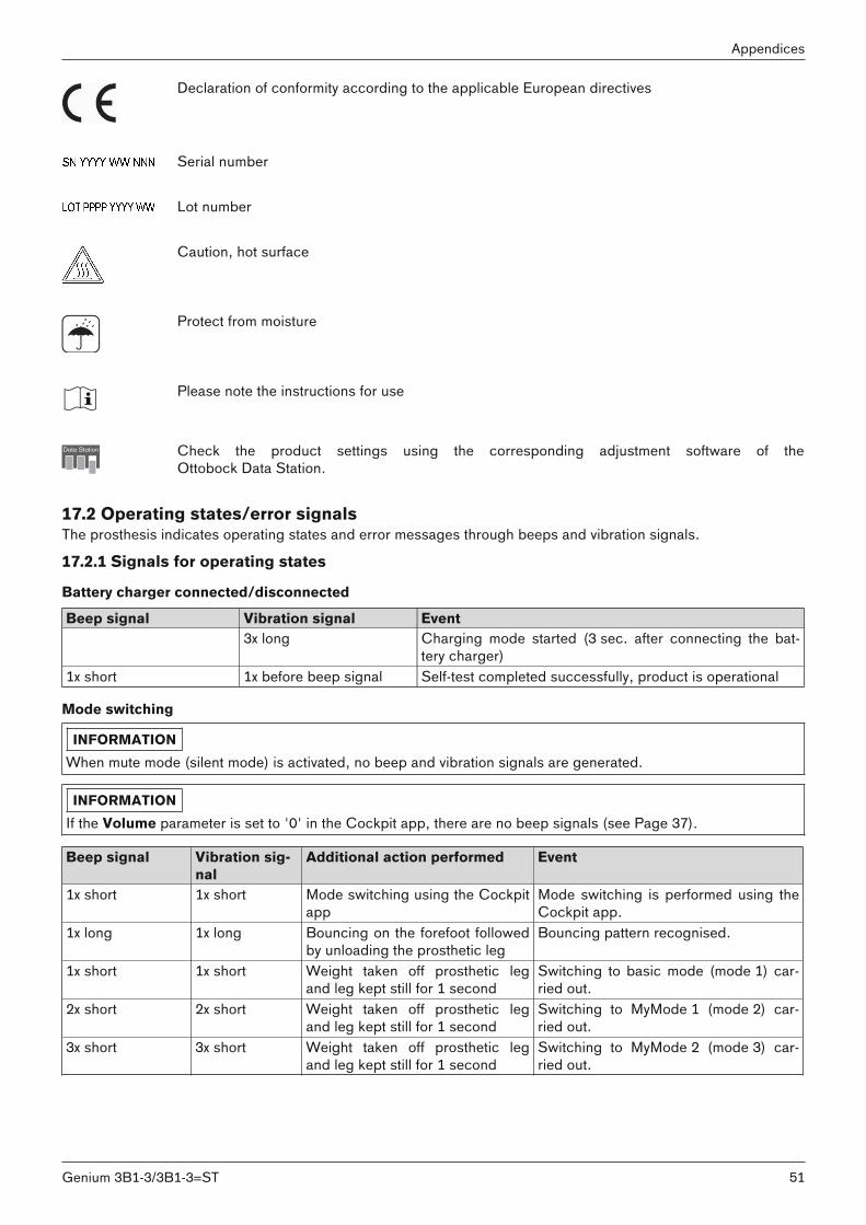
Declaration of conformity according to the applicable European directives
Serial number
Lot number
Caution, hot surface
Protect from moisture
Please note the instructions for use
Check the product settings using the corresponding adjustment software of theOttobock Data Station.
17.2 Operating states/error signalsThe prosthesis indicates operating states and error messages through beeps and vibration signals.
17.2.1 Signals for operating states
Battery charger connected/disconnected
Beep signal Vibration signal Event3x long Charging mode started (3 sec. after connecting the bat
tery charger)1x short 1x before beep signal Self-test completed successfully, product is operational
Mode switching
INFORMATIONWhen mute mode (silent mode) is activated, no beep and vibration signals are generated.
INFORMATIONIf the Volume parameter is set to '0' in the Cockpit app, there are no beep signals (see Page 37).
Beep signal Vibration signal
Additional action performed Event
1x short 1x short Mode switching using the Cockpitapp
Mode switching is performed using theCockpit app.
1x long 1x long Bouncing on the forefoot followedby unloading the prosthetic leg
Bouncing pattern recognised.
1x short 1x short Weight taken off prosthetic legand leg kept still for 1 second
Switching to basic mode (mode 1) carried out.
2x short 2x short Weight taken off prosthetic legand leg kept still for 1 second
Switching to MyMode 1 (mode 2) carried out.
3x short 3x short Weight taken off prosthetic legand leg kept still for 1 second
Switching to MyMode 2 (mode 3) carried out.
51Genium 3B1-3/3B1-3=ST
Appendices
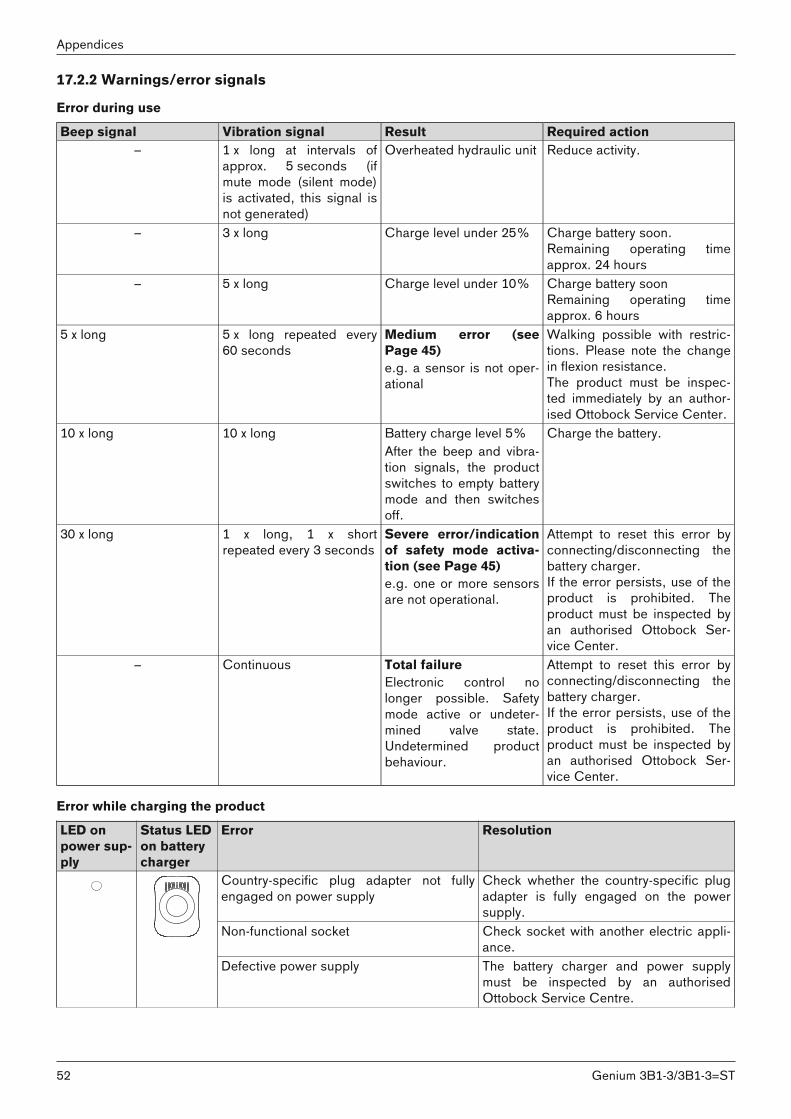
17.2.2 Warnings/error signals
Error during use
Beep signal Vibration signal Result Required action– 1 x long at intervals of
approx. 5 seconds (ifmute mode (silent mode)is activated, this signal isnot generated)
Overheated hydraulic unit Reduce activity.
– 3 x long Charge level under 25% Charge battery soon.Remaining operating timeapprox. 24 hours
– 5 x long Charge level under 10% Charge battery soonRemaining operating timeapprox. 6 hours
5 x long 5 x long repeated every60 seconds
Medium error (seePage 45)e.g. a sensor is not operational
Walking possible with restrictions. Please note the changein flexion resistance.The product must be inspected immediately by an authorised Ottobock Service Center.
10 x long 10 x long Battery charge level 5%After the beep and vibration signals, the productswitches to empty batterymode and then switchesoff.
Charge the battery.
30 x long 1 x long, 1 x shortrepeated every 3 seconds
Severe error/indicationof safety mode activation (see Page 45)e.g. one or more sensorsare not operational.
Attempt to reset this error byconnecting/disconnecting thebattery charger.If the error persists, use of theproduct is prohibited. Theproduct must be inspected byan authorised Ottobock Service Center.
– Continuous Total failureElectronic control nolonger possible. Safetymode active or undetermined valve state.Undetermined productbehaviour.
Attempt to reset this error byconnecting/disconnecting thebattery charger.If the error persists, use of theproduct is prohibited. Theproduct must be inspected byan authorised Ottobock Service Center.
Error while charging the product
LED onpower supply
Status LEDon batterycharger
Error Resolution
Country-specific plug adapter not fullyengaged on power supply
Check whether the country-specific plugadapter is fully engaged on the powersupply.
Non-functional socket Check socket with another electric appliance.
Defective power supply The battery charger and power supplymust be inspected by an authorisedOttobock Service Centre.
52
Appendices
Genium 3B1-3/3B1-3=ST

LED onpower supply
Status LEDon batterycharger
Error Resolution
No connection between battery chargerand power supply
Check whether the charging cable plug isfully engaged on the battery charger.
Defective battery charger The battery charger and power supplymust be inspected by an authorisedOttobock Service Centre.
Status LED Charging status indicator (5 LEDs)
Error Resolution
The LEDring is lit inweak purple
No LED is lit Distance between batterycharger and receiver of thecharging unit on the prosthesis too great. If the distance is more than 2 mm,the prosthesis cannot becharged.
Reduce distance betweenbattery charger and receiverof the charging unit.
LED 2 and 4 are lit up Charger excess temperature
LED 1, 3 and 5 are lit up Excessively high or lowtemperature of the prosthesis
Check whether the specified ambient conditions forcharging the battery are met(see Page 48).
The LEDring is lit upyellow
LED 3 is lit up The prosthesis is not beingchargedDistance between batterycharger and receiver of thecharging unit too great.
Connection may beimproved by reducing thedistance between the charger and receiver of the charging unit.
The LEDring is lit upgreen
The battery charger isfunctional but not connected to the receiver, or thedistance between the battery charger and receiverof the charging unit is toogreat.
Connect the battery chargeror reduce the distancebetween the charger andthe receiver of the chargingunit on the prosthesis.
The LEDring is flashing red
The prosthesis is not beingchargedDefective battery charger.
Reset the error by disconnecting and connecting thepower supply.If the error persists, the battery charger and power supply must be inspected by anauthorised Ottobock Service Center.
17.2.3 Error messages while establishing a connection with the cockpit appError message Cause CorrectionComponent was connected to another device.Establish connection?
The component was connected to another device
To disconnect the original connection, tap the "OK"button.If the original connection is not to be disconnected,tap the "Cancel" button.
Mode change failed An attempt was made toswitch to a different MyModewhile the component was inmotion (e. g. while walking)
For safety reasons, switching MyModes is only permitted when components are at rest, e. g. whilestanding or sitting.
53Genium 3B1-3/3B1-3=ST
Appendices
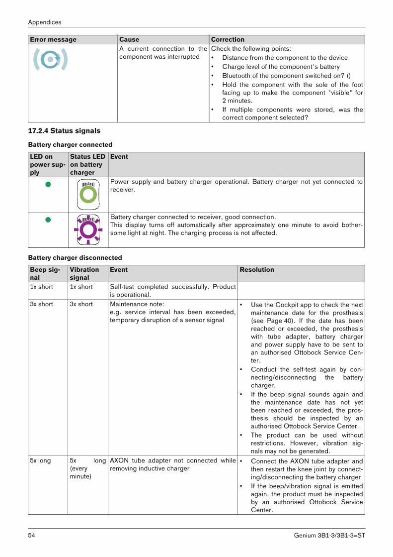
Error message Cause CorrectionA current connection to thecomponent was interrupted
Check the following points:• Distance from the component to the device• Charge level of the component's battery• Bluetooth of the component switched on? ()• Hold the component with the sole of the foot
facing up to make the component "visible" for2 minutes.
• If multiple components were stored, was thecorrect component selected?
17.2.4 Status signals
Battery charger connected
LED onpower supply
Status LEDon batterycharger
Event
Power supply and battery charger operational. Battery charger not yet connected toreceiver.
Battery charger connected to receiver, good connection.This display turns off automatically after approximately one minute to avoid bothersome light at night. The charging process is not affected.
Battery charger disconnected
Beep signal
Vibrationsignal
Event Resolution
1x short 1x short Self-test completed successfully. Productis operational.
3x short 3x short Maintenance note:e.g. service interval has been exceeded,temporary disruption of a sensor signal
• Use the Cockpit app to check the nextmaintenance date for the prosthesis(see Page 40). If the date has beenreached or exceeded, the prosthesiswith tube adapter, battery chargerand power supply have to be sent toan authorised Ottobock Service Center.
• Conduct the self-test again by connecting/disconnecting the batterycharger.
• If the beep signal sounds again andthe maintenance date has not yetbeen reached or exceeded, the prosthesis should be inspected by anauthorised Ottobock Service Center.
• The product can be used withoutrestrictions. However, vibration signals may not be generated.
5x long 5x long(everyminute)
AXON tube adapter not connected whileremoving inductive charger
• Connect the AXON tube adapter andthen restart the knee joint by connecting/disconnecting the battery charger
• If the beep/vibration signal is emittedagain, the product must be inspectedby an authorised Ottobock ServiceCenter.
54
Appendices
Genium 3B1-3/3B1-3=ST
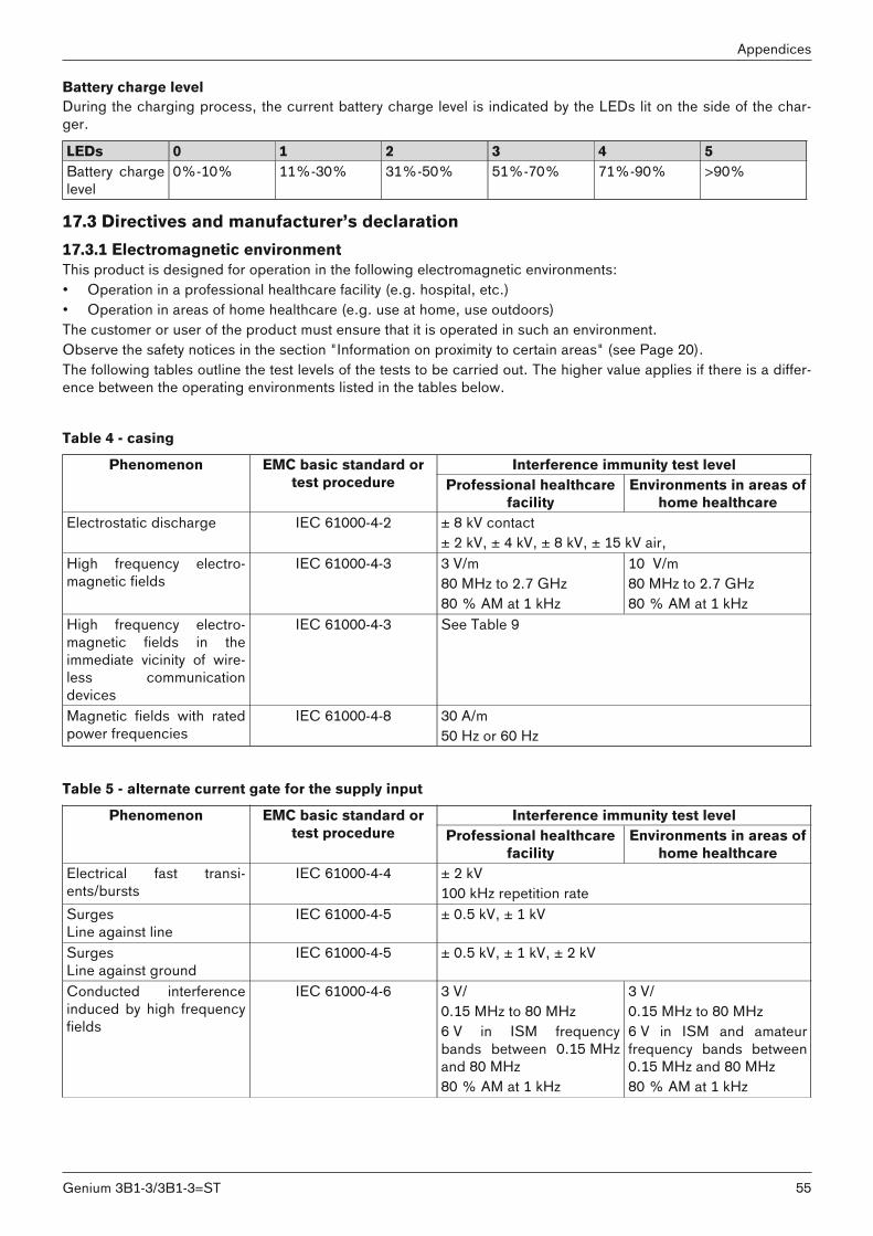
Battery charge levelDuring the charging process, the current battery charge level is indicated by the LEDs lit on the side of the charger.
LEDs 0 1 2 3 4 5Battery chargelevel
0%-10% 11%-30% 31%-50% 51%-70% 71%-90% >90%
17.3 Directives and manufacturer’s declaration17.3.1 Electromagnetic environmentThis product is designed for operation in the following electromagnetic environments:• Operation in a professional healthcare facility (e.g. hospital, etc.)• Operation in areas of home healthcare (e.g. use at home, use outdoors)The customer or user of the product must ensure that it is operated in such an environment. Observe the safety notices in the section "Information on proximity to certain areas" (see Page 20).The following tables outline the test levels of the tests to be carried out. The higher value applies if there is a difference between the operating environments listed in the tables below.
Table 4 - casing
Interference immunity test levelPhenomenon EMC basic standard ortest procedure Professional healthcare
facilityEnvironments in areas of
home healthcareElectrostatic discharge IEC 61000-4-2 ± 8 kV contact
± 2 kV, ± 4 kV, ± 8 kV, ± 15 kV air,High frequency electromagnetic fields
IEC 61000-4-3 3 V/m80 MHz to 2.7 GHz80 % AM at 1 kHz
10 V/m80 MHz to 2.7 GHz80 % AM at 1 kHz
High frequency electromagnetic fields in theimmediate vicinity of wireless communicationdevices
IEC 61000-4-3 See Table 9
Magnetic fields with ratedpower frequencies
IEC 61000-4-8 30 A/m50 Hz or 60 Hz
Table 5 - alternate current gate for the supply input
Interference immunity test levelPhenomenon EMC basic standard ortest procedure Professional healthcare
facilityEnvironments in areas of
home healthcareElectrical fast transients/bursts
IEC 61000-4-4 ± 2 kV100 kHz repetition rate
SurgesLine against line
IEC 61000-4-5 ± 0.5 kV, ± 1 kV
SurgesLine against ground
IEC 61000-4-5 ± 0.5 kV, ± 1 kV, ± 2 kV
Conducted interferenceinduced by high frequencyfields
IEC 61000-4-6 3 V/0.15 MHz to 80 MHz6 V in ISM frequencybands between 0.15 MHzand 80 MHz80 % AM at 1 kHz
3 V/0.15 MHz to 80 MHz6 V in ISM and amateurfrequency bands between0.15 MHz and 80 MHz80 % AM at 1 kHz
55Genium 3B1-3/3B1-3=ST
Appendices
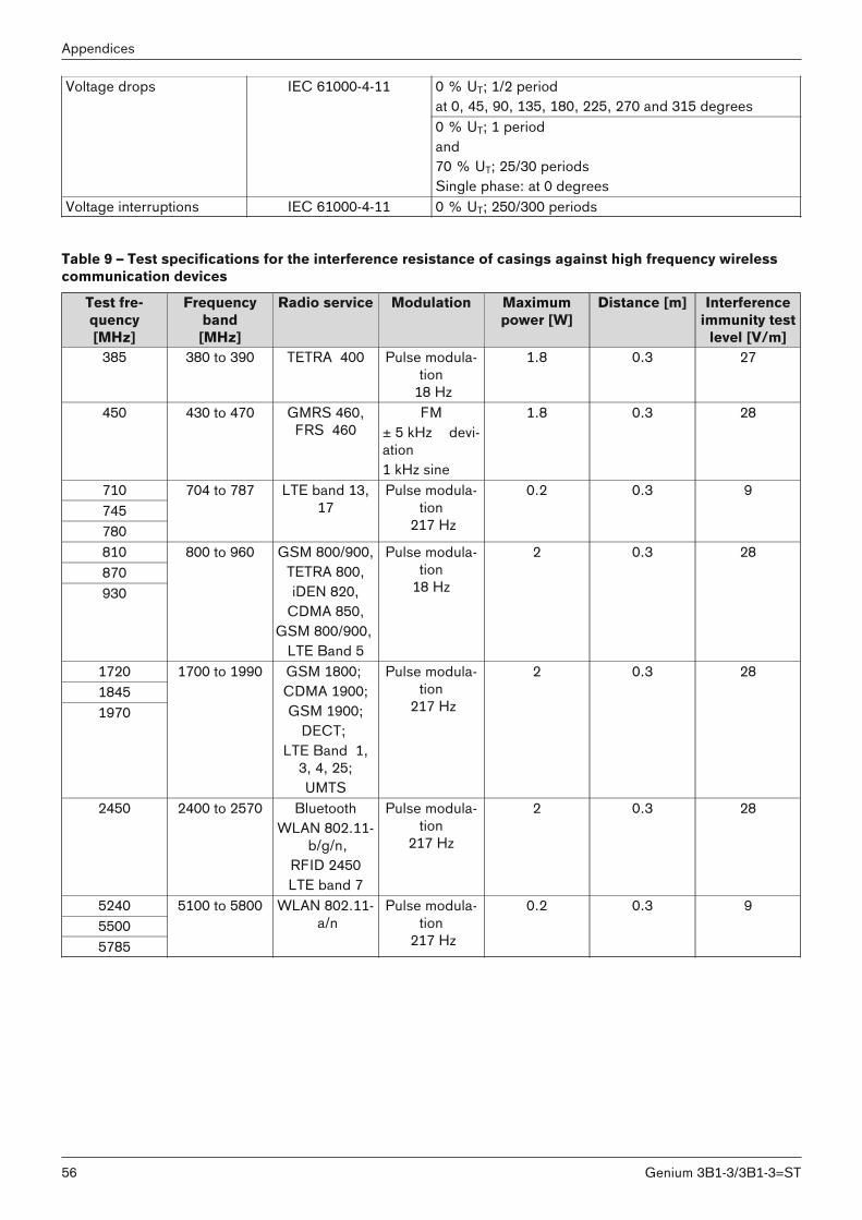
0 % UT; 1/2 periodat 0, 45, 90, 135, 180, 225, 270 and 315 degrees
Voltage drops IEC 61000-4-11
0 % UT; 1 periodand70 % UT; 25/30 periodsSingle phase: at 0 degrees
Voltage interruptions IEC 61000-4-11 0 % UT; 250/300 periods
Table 9 – Test specifications for the interference resistance of casings against high frequency wirelesscommunication devices
Test frequency[MHz]
Frequencyband[MHz]
Radio service Modulation Maximumpower [W]
Distance [m] Interferenceimmunity test
level [V/m]385 380 to 390 TETRA 400 Pulse modula
tion 18 Hz
1.8 0.3 27
450 430 to 470 GMRS 460,FRS 460
FM± 5 kHz deviation1 kHz sine
1.8 0.3 28
710745780
704 to 787 LTE band 13,17
Pulse modulation
217 Hz
0.2 0.3 9
810870930
800 to 960 GSM 800/900,TETRA 800,iDEN 820,
CDMA 850,GSM 800/900,
LTE Band 5
Pulse modulation
18 Hz
2 0.3 28
172018451970
1700 to 1990 GSM 1800; CDMA 1900;GSM 1900;
DECT; LTE Band 1,
3, 4, 25;UMTS
Pulse modulation
217 Hz
2 0.3 28
2450 2400 to 2570 BluetoothWLAN 802.11
b/g/n,RFID 2450LTE band 7
Pulse modulation
217 Hz
2 0.3 28
524055005785
5100 to 5800 WLAN 802.11 a/n
Pulse modulation
217 Hz
0.2 0.3 9
56
Appendices
Genium 3B1-3/3B1-3=ST
57Genium 3B1-3/3B1-3=ST
58 Genium 3B1-3/3B1-3=ST

59Genium 3B1-3/3B1-3=ST
Template-Version: SB_2016-10-21 · FM483 · SB_210x297
Otto Bock Healthcare Products GmbHBrehmstraße 16 · 1110 Wien · AustriaT +43-1 523 37 86 · F +43-1 523 22 [email protected] · www.ottobock.com
© O
ttobo
ck ·
647G
1380
=en-
02-1
804
The product 3B1-2/3B1-2=ST is covered by the following patents:Canada: CA 2 651 124; CA 2 714 469; CA 2 780 511; CA 2 704 792; CA 2 626 738;CA 2 780 192; CA 2 779 784China: CN 101 453 963; CN 101 909 553; CN 101 938 958; CN 102 711 672; CN 102 647 963; CN 101 346 110;
CN 102 740 804; CN 102 762 171; CN 102 724 936; CN 102 740 803; CN 104 856 787Finland: FI 110 159Germany: DE 10 2008 010 281: DE 10 2009 052 887Japan: JP 4 718 635; JP 5 619 910; JP 5 547 091; JP 5 394 579;JP 5 968 591; JP 5 678 079; JP 6 109 793; Russia: RU 2 404 730; RU 2 484 789; RU 2 533 967; RU 2 488 367; RU 2 508 078; RU2 572 741 Taiwan: R.O.C. Invention Patent No. I386194; I459936; I442912; I494095; I551277; I551278; 530278; I542335; I519292;
I517845USA: US 7 731 759; US 6 908 488; US 8 083 807, US 8 474 329; US 8 876 912; US 8 814 948; US 9 066 818;
US 9 278 013; US 9 248 031; US 9 572 690European Patent EP 1237513 in DE, FR, GB
EP 2015712 in DE, ES, FR, GB, IT, NL, SE, TREP 2240124 in DE, FR, GB, IT, NL, SE, TREP 2498724 in DE, FR, GB, IS, IT, NL, SE, TREP 2498725 in DE, FR, GBEP 2498726 in DE, FR, GB, IS, IT, NL, SE, TREP 2498727 in DE, FR, GB, IS, IT, NL, SE, TREP 2498729 in DE, FR, GBEP 2498730 in DE, FR, GBEP 2498728 in DE, FR, GBEP 2254525 in DE, FR, GB, IS, IT, NL, TREP 2222253 in DE, FR, GB, IS, IT, NL, SE, TREP 1940327 in DE, FR, GB, IS, IT, NL, SE, TREP 2772232 in DE, GB, FR, IT, NL, SE, TR, IS
Patents pending in Brazil, Germany and USA