Embed Size (px)
Citation preview

Defence R&D Canada – Atlantic
DEFENCE DÉFENSE&
Genetic Algorithm Optimisation of Multilayer
Jaumann Absorbers
Oblique Incidence
Paul Saville
Technical Memorandum
DRDC Atlantic TM 2005-283
December 2005
Copy No.________
Defence Research andDevelopment Canada
Recherche et développementpour la défense Canada

This page intentionally left blank.
Genetic Algorithm Optimisation of Multilayer Jaumann Absorbers Oblique Incidence
Paul Saville
December 2005 DRDC Atlantic TM 2005-283 Technical Memorandum
Defence R&D Canada - Atlantic

Abstract
Multilayers of spacers and resistive sheets can produce wide bandwidth microwave absorbers. Absorber bandwidth increases with the number of resistive sheets and the resistance profile through the absorber determines its performance. Absorber design requires an optimisation tool. In this paper absorber design is optimized using the Genetic Algorithm for oblique angles of incidence. The influence of incident angle on absorber bandwidth is studied for 1 to 7- layer absorbers, high permittivity spacers and protective layers. It was found that the bandwidth at normal incidence remains fairly constant to an angle of about 30 degrees. Absorber performance was maintained out to large incident angles if the absorber was designed at the large angle, though at a cost of a thicker absorber.
Résumé
De multiples couches de films résistifs et d’espaceurs peuvent être utilisées pour fabriquer des absorbants de micro-ondes large bande. La largeur de bande d’absorption augmente avec le nombre de films résistifs, et le profil de résistance à travers l’absorbant détermine le rendement de celui-ci. La conception d’absorbants requiert un outil d’optimisation. Dans le cadre des travaux décrits dans le présent rapport, l’algorithme génétique a été appliqué aux angles d’incidence obliques pour optimiser la conception d’absorbants. On a étudié l’effet de l’angle d’incidence sur la largeur de bande d’absorption pour les absorbants d’une à sept couches avec des espaceurs en matériaux à permittivité élevée et des couches de protection. On a déterminé que la largeur de bande, pour une incidence normale, reste relativement constante jusqu’à un angle d’environ 30 degrés. Le rendement de l’absorbant est conservé même pour les grands angles d’incidence lorsque l’absorbant est conçu expressément pour les grands angles. Un tel absorbant aura cependant une plus grande épaisseur.
DRDC Atlantic TM 2005-283 i

This page intentionally left blank.
ii DRDC Atlantic TM 2005-283

Executive summary
Introduction
The design of optimized multilayer microwave absorbers requires an optimization routine. The genetic algorithm has been found useful for optimising absorber designs. Here the genetic algorithm is used to optimize the sheet resistances of 1 to 7-layer absorbers for maximum bandwidth below a reflectivity of –20 dB centered at a frequency of 10 GHz over a range of oblique angles of incidence.
Results
Absorber performance is fairly constant up to an incident angle of 30 degrees after which it degrades. An absorber optimized at a high angle of incidence has overall poorer performance but still functions at the high angle. This cannot be said for an absorber optimized at normal incidence. The thickness of optimized absorbers is larger for absorbers designed at high incident angles.
Significance
The absorber designed at normal incidence is effective over a wide range of incidence angles and is the thinnest possible absorber. For surfaces where high angles of incidence are expected (ie corner reflectors) it would be advantageous to use an absorber designed for a higher angle of incidence, so that absorption is maintained.
Future plans
This modeling has been undertaken for the purposes of understanding the factors that influence absorber design, and in order that optimal absorber designs are available so that materials can be fabricated with these properties. From the modeling side, design tolerances, resistive-capacitive materials and the permittivity of real materials will be used to design absorbers. From the materials side the synthesis of stable materials with reproducible properties is being undertaken.
Saville, P.. 2005. Genetic Algorithm Optimisation of Multilayer Jaumann Absorbers: Oblique Incidence. DRDC Atlantic TM 2005-283. Defence R&D Canada – Atlantic.
DRDC Atlantic TM 2005-283 iii

Sommaire
Introduction
La conception d’absorbants de micro-ondes multicouches optimisés requiert une routine d’optimisation. On a déterminé que l’algorithme génétique était utile pour obtenir les meilleurs modèles d’absorbants. Dans le cadre des travaux décrits ici, l’algorithme génétique est utilisé afin d’optimiser la résistance des films d’absorbants d’une à sept couches pour obtenir la largeur de bande maximale avec une réflectivité inférieure à -20 dB, centrée à 10 GHz, pour une gamme d’angles d’incidence obliques.
Résultats
Le rendement des absorbants est relativement constant jusqu’à un angle d’incidence de 30 degrés, au-delà duquel le rendement diminue. Un absorbant qui est optimisé pour un grand angle d’incidence obtient un rendement global inférieur, mais fonctionne pour les grands angles. Tel n’est pas le cas d’un absorbant optimisé pour les angles d’incidence normaux. Notons cependant que les absorbants optimisés, conçus expressément pour les grands angles, ont une plus grande épaisseur.
Portée
L’absorbant conçu pour les angles d’incidence normaux fonctionne efficacement sur une plage étendue d’angles d’incidence et s’avère aussi être l’absorbant le plus mince possible. Dans le cas des surfaces qui risquent fort probablement de recevoir des ondes formant de grands angles d’incidence (p. ex. réflecteurs trièdres), il serait avantageux d’utiliser un absorbant conçu pour un plus grand angle d’incidence, de sorte que les propriétés d’absorption soient conservées.
Recherches futures
La modélisation en question a été commencée afin, d’une part, de comprendre les facteurs qui influent sur la conception d’absorbants et, d’autre part, afin de créer des modèles d’absorbants optimaux pour pouvoir fabriquer des matériaux avec les propriétés voulues. En modélisation, les tolérances de conception, les matériaux résistifs et capacitifs, ainsi que la permittivité de vrais matériaux, seront utilisés pour la conception d’absorbants. En ce qui concerne les matériaux, on a commencé à faire la synthèse de matériaux stables ayant des propriétés reproductibles.
Saville, P. 2005. Genetic Algorithm Optimization of Multilayer Jaumann Absorbers: Oblique Incidence (Optimisation des absorbants multicouches de type Jaumann grâce à l’algorithme génétique : Incidence oblique). RDDC Atlantique TM 2005-283. Recherche et développement pour la défense Canada – Atlantique.
iv DRDC Atlantic TM 2005-283

Table of contents
Abstract........................................................................................................................................ i
Executive summary ................................................................................................................... iii
Sommaire................................................................................................................................... iv
Table of contents ........................................................................................................................ v
List of figures ............................................................................................................................ vi
1. Genetic Algorithm Optimisation of Multilayer Jaumann Absorbers............................. 1
2. Theory for Calculating the Reflectivity from a Multilayer Absorber............................ 2 2.1 Absorber Design............................................................................................... 5
3. Experimental.................................................................................................................. 6
4. Results and Discussion .................................................................................................. 7 4.1 Resistive sheet thickness .................................................................................. 8 4.2 Absorber optimization for one angle of incidence ........................................... 8 4.3 Performance of absorbers at incident angles other than the optimization angle13 4.4 Absorber optimization at multiple incident angles......................................... 17 4.5 Higher spacer permittivity and protective covers........................................... 19
5. Conclusions ................................................................................................................. 21 5.1 Way ahead ...................................................................................................... 21
6. References ................................................................................................................... 22
List of symbols/abbreviations/acronyms/initialisms ................................................................ 23
Distribution list ......................................................................................................................... 24
DRDC Atlantic TM 2005-283 v
List of figures
Figure 1. Reflection/Transmission at an interface ...................................................................... 2
Figure 2. Reflectivity from a multilayer absorber. .................................................................... 4
Figure 3. The optical path difference between the two reflected waves is Λ=AB + BC – AD. When this is equal to 1/2 λ the waves are 180° out of phase and destructive interference results in a minimum. .......................................................................................................... 7
Figure 4. Optimized reflectivity profiles for TE (red) and TM (blue) polarized microwaves incident at 30 degrees on a 4-layer absorber with spacer thickness of 8.136 mm, spacer permittivity of 1.1 and resistive sheet thickness of 50x10-6 m. ........................................... 9
Figure 5. Average optimized sheet resistances as a function of incident angle for a four layer Jaumann absorber optimized for maximum bandwidth below –20 dB. Spacer thickness is adjusted at each incident angle according to Equation 19. Low resistance set correspond to sheet nearest the PEC and highest resistance set corresponds to sheet next to air. Uncertainty bars indicate resistance ranges that produced the same bandwidth. Spacer permittivity = 1.1............................................................................................................... 10
Figure 6. Optimized absorber bandwidths at oblique incidence for absorbers with 1 (black circles) to 7 (black dots) layers. Spacer permittivity = 1.1............................................... 11
Figure 7. Bandwidth of multilayer absorbers designed at normal and oblique incidence (circles, normal incidence, squares, 30 degrees, and triangles 60 degrees). ..................... 12
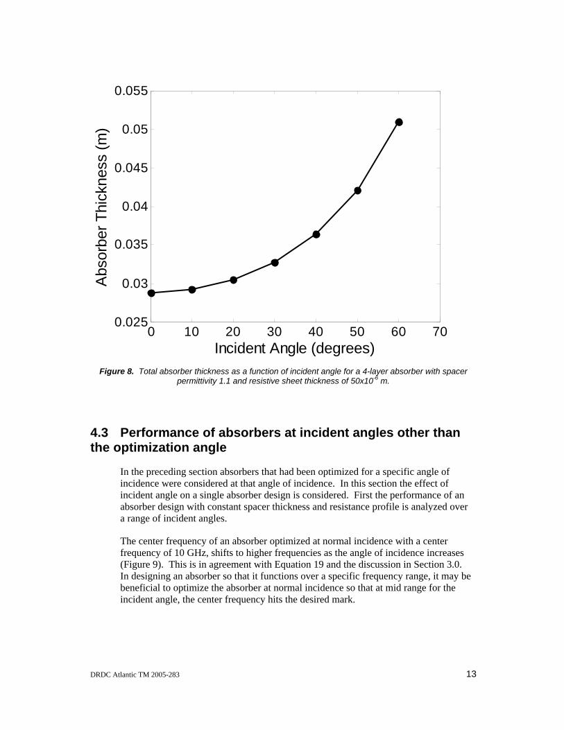
Figure 8. Total absorber thickness as a function of incident angle for a 4-layer absorber with spacer permittivity 1.1 and resistive sheet thickness of 50x10-6 m. .................................. 13
Figure 9. Shift of center frequency as a function of the incident angle of a 4-layer absorber. Initial absorber design optimized at normal incidence. Spacer thickness was 7.15 mm and the permittivity was 1.1for all angles. ........................................................................ 14
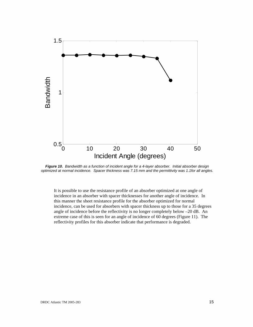
Figure 10. Bandwidth as a function of incident angle for a 4-layer absorber. Initial absorber design optimized at normal incidence. Spacer thickness was 7.15 mm and the permittivity was 1.1for all angles. ..................................................................................... 15
Figure 11. Reflectivity of a 4-layer Jaumann absorber optimized for normal incidence (solid line), with maximum bandwidth below –20 dB, spacer thickness of 7.15 mm. The same set of sheet resistances was used to calculate the absorber performance for an incidence angle of 60 degrees with spacer thickness of 13.28 mm. TM polarisation (dotted line) and TE polarisation (dashed line) at an angle of 60 degrees. Spacer permittivity = 1.1. . 16
Figure 12. Reflectivity of a 4-layer Jaumann absorber optimised for an incidence angle of 60 degrees, TM polarisation (dashed line) and TE polarisation (dotted line), with maximum
vi DRDC Atlantic TM 2005-283

bandwidth below –20 dB, spacer thickness of 13.28 mm. The same set of sheet resistances was used to calculate the absorber performance for normal incidence (solid line), spacer thickness 7.15 mm. Spacer permittivity = 1.1. ............................................ 17
Figure 13. Four layer absorber optimized for an incident angle range of 0-30 degrees. Black line indicates the maximum envelope of all TE and TM reflectivity curves at 0, 10, 20 and 30 degrees................................................................................................................... 18
Figure 14. Bandwidth as a function of incident angle for absorbers optimised from 0-30 degrees (black circles) and 0-50 degrees (blue squares) and 0 degrees (red triangles). Spacer thickness permitted to vary over the range governed by the incident angle and the spacer permittivity was 1.1................................................................................................ 19
Figure 15. Bandwidth of 2-layer absorbers optimized at different incident angles with protective layer (triangles) and no protective layer (circles). Spacer permittivity 2.0. .... 20
DRDC Atlantic TM 2005-283 vii

This page intentionally left blank.
viii DRDC Atlantic TM 2005-283

1. Genetic Algorithm Optimisation of Multilayer Jaumann Absorbers
Broadband absorbers are based on multilayer stacks of resistive sheets separated by low permittivity spacers and are known as Jaumann absorbers. Wider absorption bandwidths can be obtained by using more sheet-spacer pairs. The reflectivity from a multilayer absorber is nonlinear and cannot be analytically solved beyond one or two layers. Optimisation techniques have been used to optimize the reflectivity but are subject to becoming trapped in local minima.1
The genetic algorithm has been applied to this problem with good results.1-6 The Genetic Algorithm is a stochastic global optimisation routine loosely based on Darwin’s theory of evolution and genetics.7, 8 An evolutionary process arrives at the optimized solution over several iterations (generations), by selecting only the best (the fittest) solutions and allowing these to survive and form the basis for calculating the next round of solutions. In this manner the optimization routine evolves the initial solutions into the optimum.
In a previous paper absorber designs containing 1-7 resistive sheets were optimised at normal incidence using the Genetic Algorithm.9 These designs agreed with previously published designs,2, 10 where the resistance profile that produced optimised absorber structures, generally followed an exponential increase in the direction of the absorber-air interface. The reflectivity was also examined for absorber designs with higher permittivity spacers and a protective layer at the air/absorber interface. In that paper transmission line theory was used to model the absorber structure. In that model it was assumed that the resistive sheet thickness was negligible.
In this paper, the main focus is to study absorber performance as a function of the angle of incidence. Absorbers are optimized at oblique angles of incidence for different numbers of resistive sheets, spacer permittivity and with and without protective layers. A revised optical model of the absorber is used that includes a finite thickness for the resistive sheets.
DRDC Atlantic TM 2005-283 1

2. Theory for Calculating the Reflectivity from a Multilayer Absorber
For electromagnetic radiation incident on an interface (Figure 1), some of the radiation is reflected and some is transmitted. The angle of incidence is equal to the angle of reflection and Snell’s law of refraction relates the incident and transmitted angles in the two media with refractive indices n and n'.
ti nn θθ sinsin ′= 1
The fresnel reflection coefficient, ρ, depends on the polarisation of the electromagnetic radiation with respect to the interface, except at normal incidence. An electromagnetic wave interacting with an interface can be considered in terms of its transverse electric and transverse magnetic components.
TT
TTT nn
nn′+′−
=ρ 2
where
⎪⎩
⎪⎨⎧
=tionTEpolarisan
tionTMpolarisann
i
iT
,cos
,cos
θθ 3
Figure 1. Reflection/Transmission at an interface
n'
θi
ρ
n
θt
2 DRDC Atlantic TM 2005-283

The characteristic impedance of a medium, η, is related to the refractive index by
ηηon = 4
where ηo is the characteristic impedance of free space. Equation 4 can be used to express equations 2 and 3 in terms of the characteristic impedance.
TT
TTT ηη
ηηρ
+′−′
= 5
and
⎪⎩
⎪⎨⎧
=tionTMpolarisa
tionTEpolarisa
i
iT
,cos
,cos
θηθ
ηη 6
Equation 5 can be recast in terms of wavenumbers, k, where kkz /cos =θ and kkx /sin =θ . First use is made of the relationships ωμη =k and ωεη =/k to
rewrite the TE and TM impedances of equation 6,
zziTE kk
k ωμηθ
ηη ===cos
, ωε
ηθηη zz
iTMk
kk
=== cos 7
The fresnel reflectivity from an interface as a function of polarisation then becomes
zz
zz
TETE
TETETE kk
kk′+′′−′
=+′−′
=μμμμ
ηηηη
ρ , εεεε
ηηηη
ρ′+′′−′
=+′−′
=zz
zz
TMTM
TMTMTM kk
kk 8
If the incident radiation passes through more than a single interface, then the reflectivity coefficient, Γ, to the left of the first interface will include contributions from the reflectivity at every interface in the structure, Figure 2. Knowing the permittivity and permeability for each absorber layer, and the incident angle, the fresnel reflection coefficients can be calculated for each interface using Equation 8. This requires calculation of the wavenumber in the z-direction, kz, for each layer i
iiiiiiz kk θμεωθ coscos == 9
where fπω 2= , is the angular frequency and the angle refers to the incident angle in medium i. This angle can be calculated using the identity , and Snell’s law of reflection, Equation 9. Also using
θθ 22 cossin1 +=εμ=n , kzi becomes
DRDC Atlantic TM 2005-283 3

aaiiiiiiiz nnkk θωθμεωθ 222 sincoscos −===
for i = 1,2,…M,air 10
where the subscript a refers to the air medium. The total reflection coefficient, Γ, to the left of an interface is then given by the expression
1
1
21,
21,
1 −
−
−−
−−
Γ+
Γ+=Γ
i
i
jiTTi
jiTTi
Ti ee
δ
δ
ρρ
, for i = 2, 3, …, M+1 11
where the phase thickness of a layer i is izii dk=δ , and the actual layer thickness is di. To summarize, the reflectivity coefficient to the left of an absorber is calculated using Equation 11. First, the permittivity and permeability (or refractive indices) for each layer are obtained. The z-direction wavenumber is calculated using Equation 10, and the transverse electric and magnetic components of the fresnel reflectivity for each interface are calculated using Equation 8. The total reflectivity coefficient for each layer is calculated from Equation 11, starting at the left of the rightmost interface, where .111 −=Γ= TTρ For each successive layer Equation 11 is applied until the total reflectivity coefficient is obtained to the left of the air-absorber interface.
Figure 2. Reflectivity from a multilayer absorber.
Interface
Γ
θa θM
dM d3 d2 d1…air … Pec
θi θ1 θ2
… …
z
x
1 23ii+1… M+1 M …
ρ ρ ρ ρ ρT1 … …ρTM+1 ρTM Ti+1 Ti T3 T2
4 DRDC Atlantic TM 2005-283

The reflectivity of the absorber is calculated by
2TTR Γ= 12
and the reflectivity in decibels by
TT RdBR log10= 13
2.1 Absorber Design
The broadband absorber is of the Jaumann design using low permittivity-permeability spacers to separate resistive-capacitive sheets. Each layer of the absorber has a finite thickness. The permittivity of an RC sheet is calculated using
ii
i
oi
dCe
jj
⎟⎟⎠
⎞⎜⎜⎝
⎛−
−=Reω
εε 14
and the permeability,
oi μμ = 15
This approach makes the assumption that the real component of the permittivity is equal to the freespace permittivity.
Bandwidth is defined in terms of the frequency range over which the reflectivity is below the critical reflectivity (-10 or –20 dB), and is calculated by
⎟⎟⎠
⎞⎜⎜⎝
⎛+−
=lu
lu
ffff
BW 2 16
The bandwidth for perpendicular and parallel polarisations are used to define the objective function used to optimize the absorber structure. This objective function selects for absorber designs where the bandwidths of the two polarisations are equal at the critical reflectivity.3
( )1+−=
⊥
⊥
II
IIBW BWBW
BWBWOF 17
DRDC Atlantic TM 2005-283 5

3. Experimental
The absorbers studied in this work consisted of resistive sheets separated by dielectric spacers and a perfect electrical conductor, PEC, for backing. The basic design was evaluated with and without protective layers, where the protective layer was another sheet of the same thickness and material as a spacer. Symbolically the absorber designs are shown below, with SN/RN forming a spacer/resistive sheet pair. The subscript N refers to the Nth layer.
PEC/S1/R1/S2/R2…./SN/RN/air unprotected
PEC/S1/R1/S2/R2…./SN/RN/SN+1/air protected
Spacers had a relative permittivity of εr = 1.1, 2 and 4 and the thickness of the spacers were calculated so as to center the absorption resonance at 10 GHz. Resistive sheet thickness was 50 μm.
A bandwidth objective function given by Equation 17 was used to optimise absorber designs at oblique angles of incidence. It was found that the genetic algorithm was better able to converge on an optimized design if a reflectivity objective function was also used. The reflectivity objective function worked on an envelope of the maximum reflectivity from all polarisations and angles of incidence considered. The function was weighted for different frequency regions as
))(())(())((1
31
21
1Re ∑∑∑++=
+
+==
−+−+−=F
XNiic
XN
Niic
N
iicflectivity fRRwfRRwfRRwOF
where are weights between 1 and 2 for the different frequency bands, R(f321 ,, www i) is the reflectivity at frequency i and Rc is the critical reflectivity.
For the genetic algorithm typically a population of 200 absorbers were optimised for 50 generations with a tournament using 2 participants. The cut-off reflectivity was set at –20 dB and incident angles were run from 0-60 degrees.
6 DRDC Atlantic TM 2005-283
4. Results and Discussion
One of the first considerations is the effect of incident angle on absorber design. This is understood by considering the waves reflected and refracted by a film (Figure 3).
A
B
C
Dθi
θt
n1
n2
n3
d
Figure 3. The optical path difference between the two reflected waves is Λ=AB + BC – AD. When this is equal to 1/2 λ the waves are 180° out of phase and destructive interference results in a minimum.
The optical path difference, Λ, between a wave reflected from the first interface and a wave reflected from the second interface (Figure 3) is
tdn θcos2 2=Λ 18
When Λ is om λ2
(m=1, 2, 3 ⋅⋅⋅) the waves are out of phase by 180 degrees (the phase
difference is to dkk θδ cos2 2=Λ= or twice the phase shift in traversing the film once). This condition produces the destructive interference that results in the high absorption and bandwidth of the Jaumann absorbers.
The minimum spacer thickness required to produce destructive interference is
t
o
nd
θλcos4 2
= 19
For normal incidence 1cos =tθ , and Equation 19 reduces to 24n
d oλ= , where oλ is
the wavelength corresponding to the frequency at the centre of the absorption band. For normal incidence, a decrease in the spacer thickness can be realized by increasing the refractive index (permittivity) of the layer.
DRDC Atlantic TM 2005-283 7

For oblique incidence 1cos ⟨tθ , the spacer thickness must be greater than 24n
oλ to
produce destructive interference. Thus optimizing an absorber for oblique incidence will require thicker absorbers. Another consequence of this is that an absorber optimized for a specific central frequency at normal incidence, will see the absorption band shift to higher frequencies as the incident angle increases.
4.1 Resistive sheet thickness
First the absorber performance is considered as a function of the thickness of the resistive sheets. Qualitatively the centre frequency of the absorption band shifts to lower frequency due to the increased thickness of the absorber. This shift is negligible for a sheet thickness of 10 μm, 50 MHz for 50 μm and 600 MHz for 500 μm. The bandwidth does not change over this range. The shape of the resistance profile was similar between absorbers, though shifted in value.
4.2 Absorber optimization for one angle of incidence
It was mentioned in the theory section that electromagnetic waves will have polarisation dependent reflectivity profiles. This is observed in Figure 4, where TE and TM polarisations result in different reflectivity. The bandwidth objective function used to optimise this design (Equation 17) favours those designs that have identical bandwidths at the target reflectivity (here –20 dB).
8 DRDC Atlantic TM 2005-283

0 0.5 1 1.5 2x 10¹⁰
-40
-35
-30
-25
-20
-15
-10
-5
0
Frequency (Hz)
Ref
lect
ivity
(dB
)
Figure 4. Optimized reflectivity profiles for TE (dotted red) and TM (solid blue) polarized microwaves incident at 30 degrees on a 4-layer absorber with spacer thickness of 8.136 mm, spacer permittivity of
1.1 and resistive sheet thickness of 50x10-6 m.
Absorber optimisation at a single angle of incidence was achieved here through adjusting the values of the sheet resistance for each layer. The incident angle, sheet thickness, spacer thickness and spacer permittivity were all kept constant. Optimized absorber designs consisted of sheet resistance profiles increasing from low resistance sheets closest to the metal surface to high resistance sheets at the air/absorber interface. This is observed in Figure 5 where the average sheet resistances that produce a maximum in the objective function are plotted as a function of the incident angle.
The incident angle is seen to have little effect on the sheet resistances up to about 30 degrees. At higher angles of incidence, there is a large increase in the resistance of the outer layer and a slight decrease in the resistances of the inner layers. A similar trend is seen for other absorbers with a different number of layers. The error bars in the figure indicate the range of sheet resistances that resulted in the same optimized designs.
DRDC Atlantic TM 2005-283 9

Figure 5. Average optimized sheet resistances as a function of incident angle for a four layer Jaumann absorber optimized for maximum bandwidth below –20 dB. Spacer thickness is adjusted at each
incident angle according to Equation 19. Low resistance set correspond to sheet nearest the PEC and highest resistance set corresponds to sheet next to air. Uncertainty bars indicate resistance ranges that
produced the same bandwidth. Spacer permittivity = 1.1.
The bandwidth performance for absorber designs with an increasing number of resistive sheets and different angles of incidence is shown in Figure 6. The bandwidth is observed to decrease at an incident angle of about 30 degrees for all absorbers, with the decrease being more pronounced for absorbers with fewer layers. A single layer absorber (Salisbury screen) does not absorb below –20 dB for incident angles greater than 40 degrees.
10 DRDC Atlantic TM 2005-283

Figure 6. Optimized absorber bandwidths at oblique incidence for absorbers with 1 (black circles) to 7 (black dots) layers. Spacer permittivity = 1.1.
Some of the data from Figure 6 is replotted as bandwidth vs the number of layers in the absorber (Figure 7) for angle of incidence of 0, 30 and 60 degrees. The absorber bandwidth is seen to increase with increasing number of resistive sheets. Optimized absorbers for incident angles of 0 and 30 degrees have very similar bandwidths especially as the number of layers increases. This is not the case for an incident angle of 60 degrees where the absorber bandwidths are all considerably lower than those for normal incidence.
DRDC Atlantic TM 2005-283 11

Figure 7. Bandwidth of multilayer absorbers designed at normal and oblique incidence (circles, normal incidence, squares, 30 degrees, and triangles 60 degrees).
A penalty that is paid for using an absorber optimized for oblique angles of incidence is the increase in absorber thickness due to the increase in spacer thickness required to produce destructive interference (Equation 19). Figure 8 shows the absorber thickness as a function of the incident angle at which the absorber was optimized. The absorber thickness is seen to nearly double in going from the absorber designed to normal incidence to that at 60 degrees.
12 DRDC Atlantic TM 2005-283
0 10 20 30 40 50 60 700.025
0.03
0.035
0.04
0.045
0.05
0.055
Incident Angle (degrees)
Abs
orbe
r Thi
ckne
ss (m
)
Figure 8. Total absorber thickness as a function of incident angle for a 4-layer absorber with spacer permittivity 1.1 and resistive sheet thickness of 50x10-6 m.
4.3 Performance of absorbers at incident angles other than the optimization angle
In the preceding section absorbers that had been optimized for a specific angle of incidence were considered at that angle of incidence. In this section the effect of incident angle on a single absorber design is considered. First the performance of an absorber design with constant spacer thickness and resistance profile is analyzed over a range of incident angles.
The center frequency of an absorber optimized at normal incidence with a center frequency of 10 GHz, shifts to higher frequencies as the angle of incidence increases (Figure 9). This is in agreement with Equation 19 and the discussion in Section 3.0. In designing an absorber so that it functions over a specific frequency range, it may be beneficial to optimize the absorber at normal incidence so that at mid range for the incident angle, the center frequency hits the desired mark.
DRDC Atlantic TM 2005-283 13

0 10 20 30 408
8.5
9
9.5
10
10.5
11
11.5
12
Angle of Incidence (degrees)
Cen
ter F
requ
ency
(GH
z)
Figure 9. Shift of center frequency as a function of the incident angle of a 4-layer absorber. Initial absorber design optimized at normal incidence. Spacer thickness was 7.15 mm and the permittivity was
1.1for all angles.
As the incident angle was increased over the range 0-35 degrees, the bandwidth slowly decreased. At higher incident angles there was a rapidly degradation in bandwidth performance (Figure 10).
The benefit of this design strategy is that the total absorber thickness is constant and there is marginal degradation of absorber performance over an incident angle range of 0-35 degrees. The absorber thickness is also kept at the minimum limit for optimum absorber design.
14 DRDC Atlantic TM 2005-283
0 10 20 30 40 500.5
1
1.5
Incident Angle (degrees)
Ban
dwid
th
Figure 10. Bandwidth as a function of incident angle for a 4-layer absorber. Initial absorber design optimized at normal incidence. Spacer thickness was 7.15 mm and the permittivity was 1.1for all angles.
It is possible to use the resistance profile of an absorber optimized at one angle of incidence in an absorber with spacer thicknesses for another angle of incidence. In this manner the sheet resistance profile for the absorber optimized for normal incidence, can be used for absorbers with spacer thickness up to those for a 35 degrees angle of incidence before the reflectivity is no longer completely below –20 dB. An extreme case of this is seen for an angle of incidence of 60 degrees (Figure 11). The reflectivity profiles for this absorber indicate that performance is degraded.
DRDC Atlantic TM 2005-283 15

Figure 11. Reflectivity of a 4-layer Jaumann absorber optimized for normal incidence (solid line), with maximum bandwidth below –20 dB, spacer thickness of 7.15 mm. The same set of sheet resistances
was used to calculate the absorber performance for an incidence angle of 60 degrees with spacer thickness of 13.28 mm. TM polarisation (dotted line) and TE polarisation (dashed line) at an angle of 60
degrees. Spacer permittivity = 1.1.
In contrast, the sheet resistances from an absorber optimized for an angle of incidence of 60 degrees can be used in absorbers for smaller angles of incidence and still function with appreciable bandwidth (Figure 12). The reflectivity from these absorbers shows that the absorber performance improves as the incident angle decreases.
The bandwidth of the normal incidence absorber, obtained by optimizing the oblique design, is smaller than that obtained by optimizing the absorber design at normal incidence (ie compare the bandwidth of the solid lines in Figures 11 and 12).
16 DRDC Atlantic TM 2005-283

Figure 12. Reflectivity of a 4-layer Jaumann absorber optimised for an incidence angle of 60 degrees, TM polarisation (dashed line) and TE polarisation (dotted line), with maximum bandwidth below –20 dB, spacer thickness of 13.28 mm. The same set of sheet resistances was used to calculate the absorber
performance for normal incidence (solid line), spacer thickness 7.15 mm. Spacer permittivity = 1.1.
4.4 Absorber optimization at multiple incident angles
The results presented in the previous sections indicate that it should be possible to optimize an absorber for optimum performance over multiple angles of incidence. To optimise an absorber for a range of incident angles, the reflectivity for TE and TM polarisations was calculated at different angles over a range. For instance, Figure 13 shows the reflectivity profiles for incident angles of 0, 10, 20 and 30 degrees, and then the maximum reflectivity envelope found for all the curves. This envelope was used to optimise the bandwidth and the spacer thickness was allowed to vary between the optimum values for the minimum and maximum angles. An inherent problem with this method is that it does not center the absorption band at the central frequency.
DRDC Atlantic TM 2005-283 17

Figure 13. Four layer absorber optimized for an incident angle range of 0-30 degrees. Black line indicates the maximum envelope of all TE and TM reflectivity curves at 0, 10, 20 and 30 degrees.
The bandwidth performance as a function of incident angle of 3 absorber designs optimized for 0, 0-30 and 0-50 degrees is shown in Figure 14. The absorber optimized at normal incidence is observed to outperform the absorber optimized over the 0-30 degree range. The 0-50 degree optimized absorber performs to a higher angle of incidence though with a slightly lower bandwidth than the other absorbers.
18 DRDC Atlantic TM 2005-283
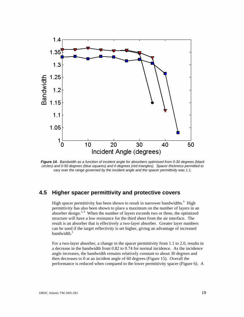
Figure 14. Bandwidth as a function of incident angle for absorbers optimised from 0-30 degrees (black circles) and 0-50 degrees (blue squares) and 0 degrees (red triangles). Spacer thickness permitted to
vary over the range governed by the incident angle and the spacer permittivity was 1.1.
4.5 Higher spacer permittivity and protective covers
High spacer permittivity has been shown to result in narrower bandwidths.9 High permittivity has also been shown to place a maximum on the number of layers in an absorber design.3, 9 When the number of layers exceeds two or three, the optimized structure will have a low resistance for the third sheet from the air interface. The result is an absorber that is effectively a two-layer absorber. Greater layer numbers can be used if the target reflectivity is set higher, giving an advantage of increased bandwidth.3
For a two-layer absorber, a change in the spacer permittivity from 1.1 to 2.0, results in a decrease in the bandwidth from 0.82 to 0.74 for normal incidence. As the incidence angle increases, the bandwidth remains relatively constant to about 30 degrees and then decreases to 0 at an incident angle of 60 degrees (Figure 15). Overall the performance is reduced when compared to the lower permittivity spacer (Figure 6). A
DRDC Atlantic TM 2005-283 19

benefit of a higher permittivity spacer is a thinner absorber (7.6 mm vs 14.4 mm for the lower permittivity absorber).
0 10 20 30 40 50 600
0.2
0.4
0.6
0.8
1
1.2
1.4
Incident Angle (degrees)
Ban
dwid
th
Figure 15. Bandwidth of 2-layer absorbers optimized at different incident angles with protective layer (triangles) and no protective layer (circles). Spacer permittivity 2.0.
Addition of a protective layer at the air-absorber interface has been shown to improve absorber performance at normal incidence. The protective layer results in an N-layer absorber behaving as an (N+1)-layer absorber with a wider bandwidth. This is seen in Figure 15 where there is a marked increase in the performance at normal incidence. The bandwidth remains larger than that produced by an unprotected absorber to an angle of incidence of about 40 degrees, after which the unprotected absorber appears to perform better.
20 DRDC Atlantic TM 2005-283

5. Conclusions
The revised model used for calculating the reflectivity from a layered absorber is consistent with the transmission line model used previously. Having a finite thickness for the resistive sheets resulted in the centre frequency of the absorption band shifting to lower frequency. The bandwidth remained constant over the thickness range studied, while the shape of the resistance profile remained constant, though shifted.
The bandwidth of an absorber is not greatly dependent on the incident angle from normal incidence to 30 degrees. At higher incident angles the bandwidth decreases.
Several strategies were investigated for optimizing absorbers at oblique angles of incidence. The normal incidence optimized absorber resulted in the absorber design with the highest bandwidth out to 30 degrees. Optimisation over a range of incident angles pushed the bandwidth performance out to larger incident angles at the cost of overall poorer bandwidth. The advantage to optimizing an absorber design at a high angle of incidence is that the absorber will perform with slightly increasing bandwidth to normal incidence, whereas the converse is not true: an absorber optimized at normal incidence has very poor bandwidth at high incident angles.
Optimised designs of an absorber at different angles of incidence maintained a fairly constant sheet resistance profile, except for the outer layer, which was found to increase with incident angle after about 30 degrees. The thickness of these absorbers increased with incident angle.
The bandwidth performance increases with the number of layers in the absorber design and decreased with increasing spacer permittivity. A protective layer at the air/absorber interface increased the absorber bandwidth at lower angles and decreased it at higher angles.
5.1 Way ahead
The model used in this work was developed so that resistive-capacitive materials capacitance could be included. The capacitive term should give an added degree of freedom to producing better absorber designs. This model can also be adapted to optimize absorbers based on the permittivity of existing materials. This model still has two shortcomings: the frequency dependency of the materials is not considered and the real component of the permittivity is set to unity for the resistive sheets. This can be accounted for by working with real materials.
The results obtained here are nonetheless valuable as a guide for material synthesis and subsequent fabrication of optimised radar absorbers. It may not be possible to reproducibly produce absorbing materials with the desired resistance characteristics, especially where the optimum absorber design has a fine tolerance in resistance or sheet thickness. To this end modeling should be used to find design tolerances.
DRDC Atlantic TM 2005-283 21

6. References
1. Michielssen, E.; Ranjithan, S.; Mittra, R., Optimal Multilayer Filter Design Using Real Coded Genetic Algorithms. Optoelectronics, IEE Proc.-J 1992, 139, (6), 413-420.
2. Chambers, B.; Tennant, A. In Application of Genetic Algorithms to the Optimisation of Wideband Jaumann Radar Absorbers for Normal and Oblique Incidence, Proceedings of the 16th Annual Meeting on Antenna Measurement Techniques Association, 1994; 1994; pp 94-99.
3. Chambers, B.; Tennant, A., Optimised design of Jaumann radar absorbing materials using a genetic algorithm. IEE Proceedings Radar, Sonar and Navigation 1996, 143, (1), 23-30.
4. Michielssen, E.; Sajer, J.-M.; Mittra, R., Pareto-optimal Design of Broadband Microwave Absorbers Using Genetic Algorithms. IEEE 1993, 1167-1170.
5. Michielssen, E.; Sajer, J.-M.; Ranjithan, S.; Mittra, R., Design of Lightweight, Broad-Band Microwave Absorbers Using Genetic Algorithms. IEEE Transactions on Microwave Theory and Techniques 1993, 41, (6/7), 1024-1031.
6. Weile, D. S.; Michielssen, E.; Goldberg, D. E., Genetic Algorithm Design of Pareto Optimal Broadband Microwave Absorbers. IEEE Transactions on Electromagnetic Compatibility 1996, 38, (3), 518 - 525.
7. Deb, K., Multi-Objective Optimization using Evolutionary Algorithms. John Wiley and Sons: Singapore, 2001.
8. Deb, K.; Pratap, A.; Agarwal, S.; Meyarivan, T. A Fast and Elitist Multi-Objective Genetic Algorithm: NSGA-II; KanGAL Report No. 200001; Kanpur Genetic Algorithms Laboratory: Kanpur, 2000; p 20.
9. Saville, P. Genetic Algorithm Optimisation of Jaumann Layers: Use of Resistive Sheets; DRDC Atlantic TM 2005 - 123; DRDC Atlantic: May 2005, 2005.
10. Nortier, J. R., Van der Neut, C.A., Baker, D.E., Tables for the Design of Jaumann Microwave Absorber. Microwave Journal 1987, (September), 219-222.
22 DRDC Atlantic TM 2005-283

List of symbols/abbreviations/acronyms/initialisms
DND Department of National Defence
dB Decibel
N The Number of Resistive Sheets in the Absorber
PEC Perfect Electrical Conductor
R Sheet Resistance in Ohms/sq (Ω/sq)
RAM Radar Absorbing Material
DRDC Atlantic TM 2005-283 23

Distribution list Note No.: DRDC ATLANTIC DLP/ LIST PART 1: CONTROLLED BY DRDC ATLANTIC LIBRARY 2 DRDC ATLANTIC LIBRARY FILE COPIES 3 DRDC ATLANTIC LIBRARY (SPARES) 1 DLP LIBRARY 1 DRDC Ottawa, Dr Satish Kashyap 1 DRDC Atlantic, Dr Dan Hut 1 AUTHOR 9 TOTAL LIST PART 1
------------------------------------------------------------------------------------------------------ LIST PART 2: DISTRIBUTED BY DRDKIM 3 1 NDHQ/ DRDKIM 3 (scanned and stored as black & white image, low resolution - laser reprints available on request )
1 NDHQ/DMSS
1 NDHQ/DMSS 2-5-4
1 NDHQ/DMPPD 4
1 NDHQ/DMRS 7 1 NDHQ/MRCC 6 TOTAL LIST PART 2 15 TOTAL COPIES REQUIRED ------------------------------------------------------------------------------------------------------ Original document held by DRDC ATLANTIC Drafting Office
Any requests by DRDC ATLANTIC staff for extra copies of this document should be directed to the DRDC ATLANTIC LIBRARY.
24 DRDC Atlantic TM 2005-283

UNCLASSIFIED
DOCUMENT CONTROL DATA(Security classification of the title, body of abstract and indexing annotation must be entered when the overall document is classified)
1. ORIGINATOR (The name and address of the organization preparing the document, Organizationsfor whom the document was prepared, e.g. Centre sponsoring a contractor's document, or taskingagency, are entered in section 8.)
Publishing: DRDC AtlanticPerforming: DRDC AtlanticMonitoring:Contracting:
2. SECURITY CLASSIFICATION(Overall security classification of the documentincluding special warning terms if applicable.)
UNCLASSIFIED
3. TITLE (The complete document title as indicated on the title page. Its classification is indicated by the appropriate abbreviation (S, C, R, or U) in parenthesis atthe end of the title)
Genetic Algorithm Optimization of Multilayer Jaumann Absorbers Oblique Incidence (U)
4. AUTHORS (First name, middle initial and last name. If military, show rank, e.g. Maj. John E. Doe.)
Paul Saville
5. DATE OF PUBLICATION(Month and year of publication of document.)
December 2005
6a NO. OF PAGES(Total containing information, includingAnnexes, Appendices, etc.)
40
6b. NO. OF REFS(Total cited in document.)
7. DESCRIPTIVE NOTES (The category of the document, e.g. technical document, technical note or memorandum. If appropriate, enter the type ofdocument, e.g. interim, progress, summary, annual or final. Give the inclusive dates when a specific reporting period is covered.)
Technical Memorandum
8. SPONSORING ACTIVITY (The names of the department project office or laboratory sponsoring the research and development − include address.)
Sponsoring:Tasking:
9a. PROJECT OR GRANT NO. (If appropriate, the applicableresearch and development project or grant under which the document waswritten. Please specify whether project or grant.)
11g
9b. CONTRACT NO. (If appropriate, the applicable number under whichthe document was written.)
10a. ORIGINATOR'S DOCUMENT NUMBER (The officialdocument number by which the document is identified by the originatingactivity. This number must be unique to this document)
DRDC Atlantic TM 2005−283
10b. OTHER DOCUMENT NO(s). (Any other numbers under whichmay be assigned this document either by the originator or by thesponsor.)
11. DOCUMENT AVAILABILITY (Any limitations on the dissemination of the document, other than those imposed by security classification.)
Unlimited distribution
12. DOCUMENT ANNOUNCEMENT (Any limitation to the bibliographic announcement of this document. This will normally correspond to the DocumentAvailability (11), However, when further distribution (beyond the audience specified in (11) is possible, a wider announcement audience may be selected.))
Unlimited announcement
UNCLASSIFIED

UNCLASSIFIED
DOCUMENT CONTROL DATA(Security classification of the title, body of abstract and indexing annotation must be entered when the overall document is classified)
13. ABSTRACT (A brief and factual summary of the document. It may also appear elsewhere in the body of the document itself. It is highly desirable that the abstract ofclassified documents be unclassified. Each paragraph of the abstract shall begin with an indication of the security classification of the information in the paragraph(unless the document itself is unclassified) represented as (S), (C), (R), or (U). It is not necessary to include here abstracts in both official languages unless the text isbilingual.)
(U) Multilayers of spacers and resistive sheets can produce wide bandwidth microwave absorbers. Absorberbandwidth increases with the number of resistive sheets and the resistance profile through the absorberdetermines its performance. Absorber design requires an optimisation tool. In this paper absorber design isoptimized using the Genetic Algorithm for oblique angles of incidence. The influence of incident angle onabsorber bandwidth is studied for 1 to 7− layer absorbers, high permittivity spacers and protective layers. It wasfound that the bandwidth at normal incidence remains fairly constant to an angle of about 30 degrees. Absorberperformance was maintained out to large incident angles if the absorber was designed at the large angle,though at a cost of a thicker absorber.
(U) De multiples couches de films résistifs et d’espaceurs peuvent être utilisées pour fabriquer des absorbants demicro−ondes large bande. La largeur de bande d’absorption augmente avec le nombre de films résistifs, et leprofil de résistance à travers l’absorbant détermine le rendement de celui−ci. La conception d’absorbantsrequiert un outil d’optimisation. Dans le cadre des travaux décrits dans le présent rapport, l’algorithmegénétique a été appliqué aux angles d’incidence obliques pour optimiser la conception d’absorbants. On aétudié l’effet de l’angle d’incidence sur la largeur de bande d’absorption pour les absorbants d’une à septcouches avec des espaceurs en matériaux à permittivité élevée et des couches de protection. On a déterminéque la largeur de bande, pour une incidence normale, reste relativement constante jusqu’à un angle d’environ30 degrés. Le rendement de l’absorbant est conservé même pour les grands angles d’incidence lorsquel’absorbant est conçu expressément pour les grands angles. Un tel absorbant aura cependant une plus grandeépaisseur.
14. KEYWORDS, DESCRIPTORS or IDENTIFIERS (Technically meaningful terms or short phrases that characterize a document and could be helpful in cataloguing thedocument. They should be selected so that no security classification is required. Identifiers, such as equipment model designation, trade name, military project codename, geographic location may also be included. If possible keywords should be selected from a published thesaurus, e.g. Thesaurus of Engineering and ScientificTerms (TEST) and that thesaurus identified. If it is not possible to select indexing terms which are Unclassified, the classification of each should be indicated as withthe title.)
(U) Radar Absorbing Material, Microwave, Absorber, Genetic Algorithm, Oblique, Angle of Incidence, Optimization
UNCLASSIFIED

This page intentionally left blank.


![Northumbria Research Linknrl.northumbria.ac.uk/23520/1/EPESJournal.pdf · 2019. 10. 12. · Genetic Algorithms (GA) proved to be popular in solving optimisation problems. Ould [6]](https://img.dokumen.tips/doc/110x75/5fdf468322c6fb41550b6553/northumbria-research-2019-10-12-genetic-algorithms-ga-proved-to-be-popular.jpg)