Embed Size (px)
Citation preview
IQ Switch®
ProxSense® Series
Copyright © Azoteq (Pty) Ltd 2015. Trackpad Module Datasheet V1.03 Page 1 of 20
All rights reserved. September 2015
48
mm
48
mm
60m
m
40
mm
48
mm
54m
m
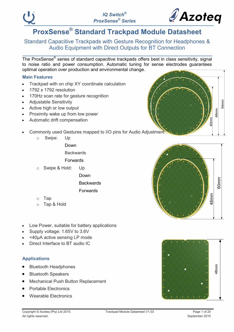
ProxSense® Standard Trackpad Module Datasheet
Standard Capacitive Trackpads with Gesture Recognition for Headphones & Audio Equipment with Direct Outputs for BT Connection
The ProxSense® series of standard capacitive trackpads offers best in class sensitivity, signal
to noise ratio and power consumption. Automatic tuning for sense electrodes guarantees optimal operation over production and environmental change.
Main Features
Trackpad with on chip XY coordinate calculation
1792 x 1792 resolution
170Hz scan rate for gesture recognition
Adjustable Sensitivity
Active high or low output
Proximity wake up from low power
Automatic drift compensation
Commonly used Gestures mapped to I/O pins for Audio Adjustment
o Swipe: Up
Down
Backwards
Forwards
o Swipe & Hold: Up
Down
Backwards
Forwards
o Tap
o Tap & Hold
Low Power, suitable for battery applications
Supply voltage: 1.65V to 3.6V
<40µA active sensing LP mode
Direct Interface to BT audio IC
Applications
Bluetooth Headphones
Bluetooth Speakers
Mechanical Push Button Replacement
Portable Electronics
Wearable Electronics
IQ Switch®
ProxSense® Series
Copyright © Azoteq (Pty) Ltd 2015. Trackpad Module Datasheet V1.03 Page 2 of 20
All rights reserved. September 2015
Contents
1 HARDWARE DESCRIPTION .................................................................................................................................. 3
2 TPR40 ................................................................................................................................................................. 7
3 TPR48 ................................................................................................................................................................. 8
4 TPR54 ................................................................................................................................................................. 9
5 TPE60 ................................................................................................................................................................ 10
6 TPE48 ................................................................................................................................................................ 11
7 TPS48 ................................................................................................................................................................ 12
8 GESTURE IMPLEMENTATION ............................................................................................................................. 13
9 SPECIFICATIONS ................................................................................................................................................ 17
10 ORDERING INFORMATION ................................................................................................................................ 19
APPENDIX A. CONTACT INFORMATION .................................................................................................................. 20
Datasheet Revision History
Version Description Date
1.00 Preliminary Draft May 2015
1.01 First Release June 2015
1.02 Updated ordering Information for Value Line August 2015
1.03 Update Illustrations Sept 2015

IQ Switch®
ProxSense® Series
Copyright © Azoteq (Pty) Ltd 2015. Trackpad Module Datasheet V1.03 Page 3 of 20
All rights reserved. September 2015
1 Hardware Description
All trackpad modules are available on RoHS2 and REACH compliant FR4 PCB material. The module PCBs are 1mm thick and have an OSP finish, with tinned pads for the user required solder points. The standard modules are not Halogen free. The trackpad sensing is done with IQS572, connected to an 8x8 diamond grid for 1792 pixel resolution in the X and Y directions. The modules are supplied with 3M double sided adhesive tape. The modules do not include any connector to BT IC.
Table 1.1 Summary of Trackpad Offerings
Module Name Shape Size
TPR40 Round Ø40mm
TPR48 Round Ø48mm
TPR54 Round Ø54mm
TPE60 Ellipse 60mm x 46mm
TPE48 Ellipse 48mm x 38mm
TPS48 Rectangle 48mm x 38mm
Two of the trackpad modules (TPR40 and TPR48) are also available in the Value Line series. A comparison between the Performance Line and Value Line can be found in Table 1.2.
Table 1.2 Performance Line vs. Value Line.
PCB Sensor IC Resolution RoHS REACH
Performance Line FR4 IQS572 1792 x1792 Yes Yes
Value Line CEM-1 IQS525 1024 x 1024 Yes No
PCB Specification 1.2
All 6 modules offered adhere to the following PCB specifications for the Performance Line:
- Material: 2-layer, FR4 PCB (non-HF material)
- Conductor: 35μm Copper (1oz. Cu)
- Finish: OSP (tinned)
- Size: Module Specific
- PCB Final Thickness = 1.0mm +/- 10%
- Outline: Precision DIE-CUT Profile
TPR40 and TPR48 are also offered in the Value Line:
- Material: 2-layer, CEM-1* PCB (non-HF material)
- Conductor: 35μm Copper (1oz. Cu)
- Finish: OSP (tinned)
- Size: Module Specific
- PCB Final Thickness = 1.0mm +/- 10%
- Outline: Precision DIE-CUT Profile
*Please note that the Value Line module does not come with REACH certification.
IQ Switch®
ProxSense® Series
Copyright © Azoteq (Pty) Ltd 2015. Trackpad Module Datasheet V1.03 Page 4 of 20
All rights reserved. September 2015
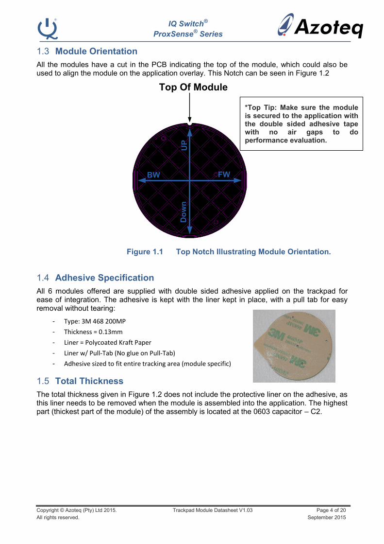
Module Orientation 1.3
All the modules have a cut in the PCB indicating the top of the module, which could also be used to align the module on the application overlay. This Notch can be seen in Figure 1.2
Top Of Module
UP
Do
wn
FWBW
Figure 1.1 Top Notch Illustrating Module Orientation.
Adhesive Specification 1.4
All 6 modules offered are supplied with double sided adhesive applied on the trackpad for ease of integration. The adhesive is kept with the liner kept in place, with a pull tab for easy removal without tearing:
- Type: 3M 468 200MP
- Thickness = 0.13mm
- Liner = Polycoated Kraft Paper
- Liner w/ Pull-Tab (No glue on Pull-Tab)
- Adhesive sized to fit entire tracking area (module specific)
Total Thickness 1.5
The total thickness given in Figure 1.2 does not include the protective liner on the adhesive, as this liner needs to be removed when the module is assembled into the application. The highest part (thickest part of the module) of the assembly is located at the 0603 capacitor – C2.
*Top Tip: Make sure the module is secured to the application with the double sided adhesive tape with no air gaps to do performance evaluation.
IQ Switch®
ProxSense® Series
Copyright © Azoteq (Pty) Ltd 2015. Trackpad Module Datasheet V1.03 Page 5 of 20
All rights reserved. September 2015
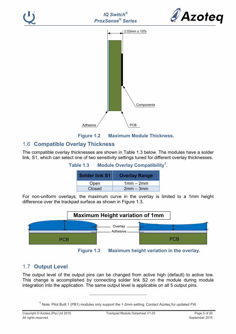
2.03mm ± 10%
Adhesive PCB
Components
Figure 1.2 Maximum Module Thickness.
Compatible Overlay Thickness 1.6
The compatible overlay thicknesses are shown in Table 1.3 below. The modules have a solder link, S1, which can select one of two sensitivity settings tuned for different overlay thicknesses.
Table 1.3 Module Overlay Compatibility1.
Solder link S1 Overlay Range
Open 1mm – 2mm
Closed 2mm – 3mm
For non-uniform overlays, the maximum curve in the overlay is limited to a 1mm height difference over the trackpad surface as shown in Figure 1.3.
Maximum Height variation of 1mm
PCB PCB
Adhesive
Overlay
Figure 1.3 Maximum height variation in the overlay.
Output Level 1.7
The output level of the output pins can be changed from active high (default) to active low. This change is accomplished by connecting solder link S2 on the module during module integration into the application. The same output level is applicable on all 5 output pins.
1 Note: Pilot Built 1 (PB1) modules only support the 1-2mm setting. Contact Azoteq for updated FW.

IQ Switch®
ProxSense® Series
Copyright © Azoteq (Pty) Ltd 2015. Trackpad Module Datasheet V1.03 Page 6 of 20
All rights reserved. September 2015
Table 1.4 Module Output Pin Level.
Solder link S2 Output Level
Open Active High
Closed Active Low
Finger Sizes 1.8
Because the modules are different physical sizes, but keep the same resolution, the trackpad pitch is different between the modules. Therefore a small variation in minimum finger size is expected. The smallest and largest finger sizes allowed for valid gestures on each module are shown in Table 1.5 below.
Table 1.5 Module Compatible Finger Sizes.
Module Min Finger Diameter
TPR40 6.7 mm
TPR48 8.0 mm
TPR54 9.0 mm
TPE60 9.0 mm
TPE48 7.2 mm
TPS48 7.2 mm

IQ Switch®
ProxSense® Series
Copyright © Azoteq (Pty) Ltd 2015. Trackpad Module Datasheet V1.03 Page 7 of 20
All rights reserved. September 2015
2 TPR40
The TPR40 is a ø40mm round trackpad. A representation of the module can be found in Figure 2.1.
Figure 2.1 TPR40 – Module Representation.
Figure 2.2 TPR40 PCB Dimensions.
IQ Switch®
ProxSense® Series
Copyright © Azoteq (Pty) Ltd 2015. Trackpad Module Datasheet V1.03 Page 8 of 20
All rights reserved. September 2015
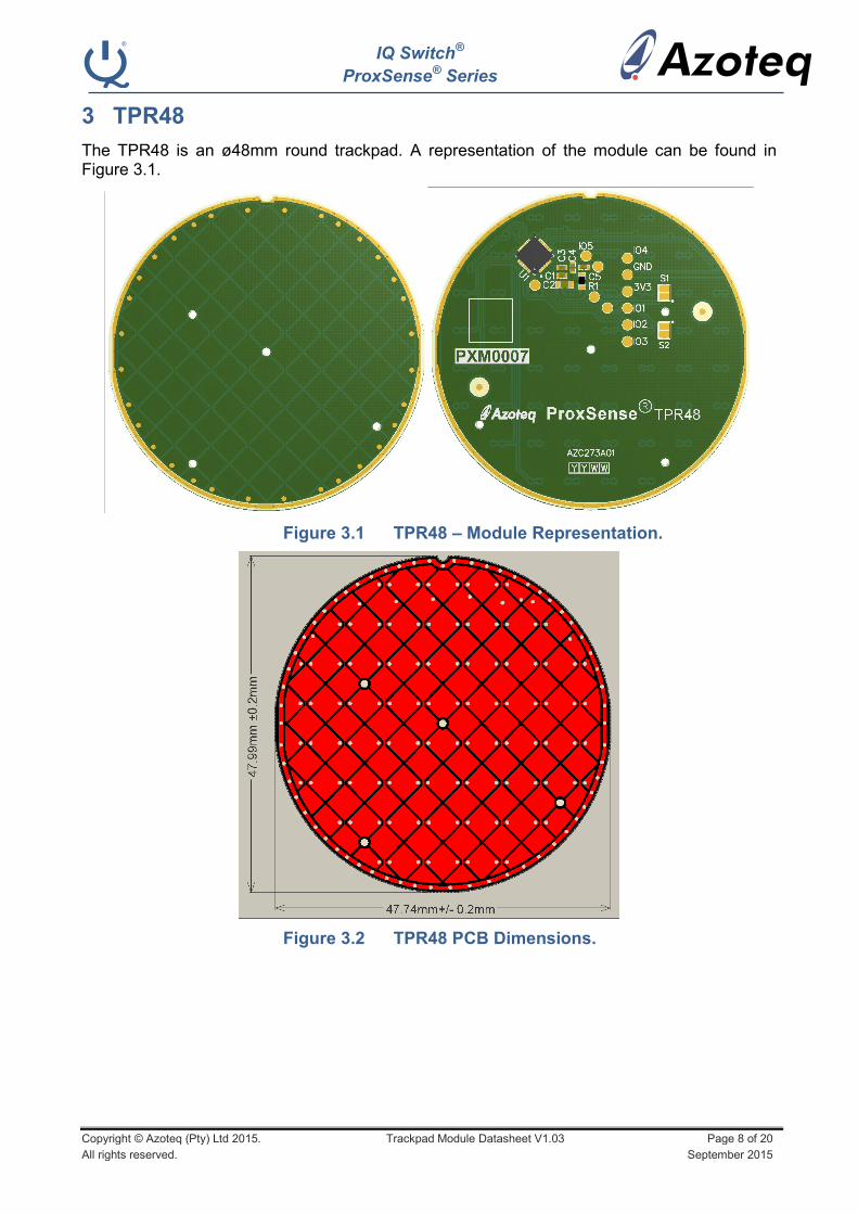
3 TPR48
The TPR48 is an ø48mm round trackpad. A representation of the module can be found in Figure 3.1.
Figure 3.1 TPR48 – Module Representation.
Figure 3.2 TPR48 PCB Dimensions.
IQ Switch®
ProxSense® Series
Copyright © Azoteq (Pty) Ltd 2015. Trackpad Module Datasheet V1.03 Page 9 of 20
All rights reserved. September 2015
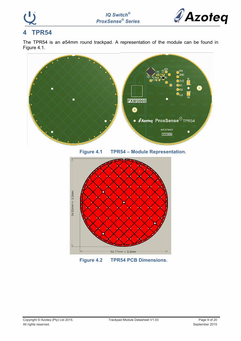
4 TPR54
The TPR54 is an ø54mm round trackpad. A representation of the module can be found in Figure 4.1.
Figure 4.1 TPR54 – Module Representation.
Figure 4.2 TPR54 PCB Dimensions.
IQ Switch®
ProxSense® Series
Copyright © Azoteq (Pty) Ltd 2015. Trackpad Module Datasheet V1.03 Page 10 of 20
All rights reserved. September 2015
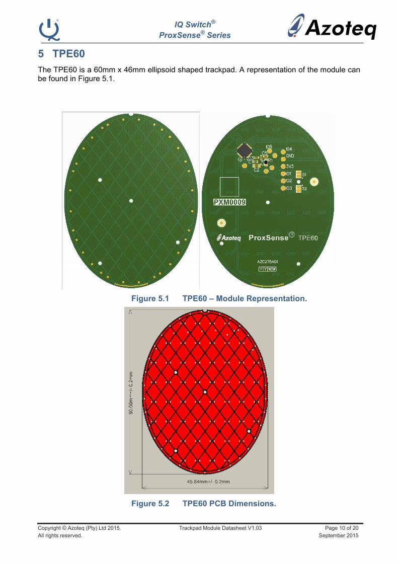
5 TPE60
The TPE60 is a 60mm x 46mm ellipsoid shaped trackpad. A representation of the module can be found in Figure 5.1.
Figure 5.1 TPE60 – Module Representation.
Figure 5.2 TPE60 PCB Dimensions.
IQ Switch®
ProxSense® Series
Copyright © Azoteq (Pty) Ltd 2015. Trackpad Module Datasheet V1.03 Page 11 of 20
All rights reserved. September 2015
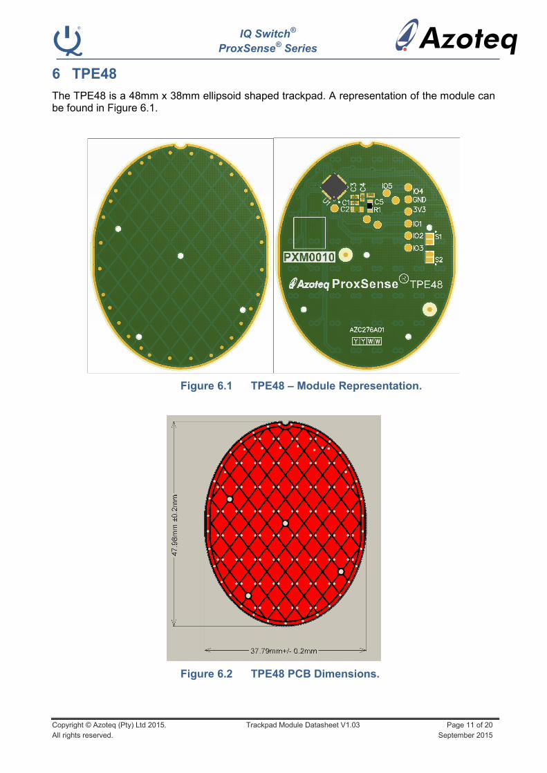
6 TPE48
The TPE48 is a 48mm x 38mm ellipsoid shaped trackpad. A representation of the module can be found in Figure 6.1.
Figure 6.1 TPE48 – Module Representation.
Figure 6.2 TPE48 PCB Dimensions.
IQ Switch®
ProxSense® Series
Copyright © Azoteq (Pty) Ltd 2015. Trackpad Module Datasheet V1.03 Page 12 of 20
All rights reserved. September 2015
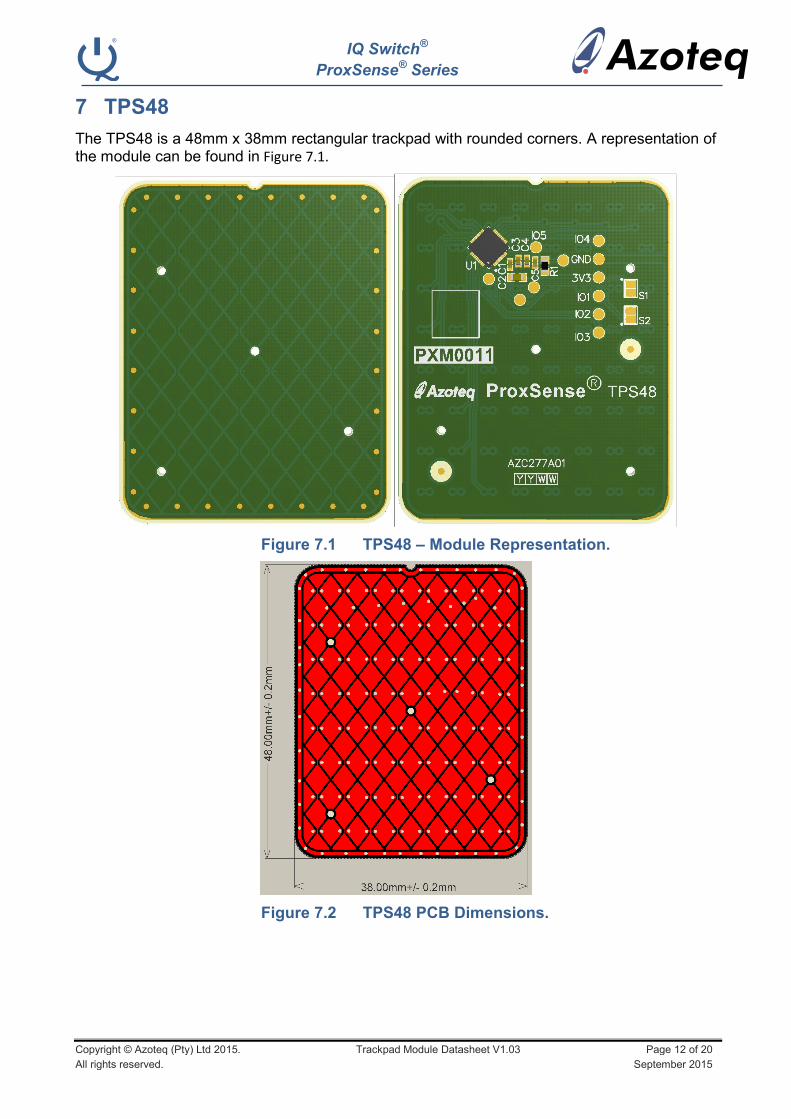
7 TPS48
The TPS48 is a 48mm x 38mm rectangular trackpad with rounded corners. A representation of the module can be found in Figure 7.1.
Figure 7.1 TPS48 – Module Representation.
Figure 7.2 TPS48 PCB Dimensions.

IQ Switch®
ProxSense® Series
Copyright © Azoteq (Pty) Ltd 2015. Trackpad Module Datasheet V1.03 Page 13 of 20
All rights reserved. September 2015
8 Gesture Implementation
Swipe Gestures 8.1
There are four swipe gestures that can be detected by the trackpad modules, as shown in Figure 8.1 below.
Figure 8.1 Illustrations off the 4 swipe gestures that can be detected by the trackpad modules.
Each time any of the swipe gestures are performed correctly (correct finger action within a 18ms to 1 second window), the corresponding I/O pin of the trackpad will output a single 200ms pulse to the Bluetooth IC. The user has the option to select a high (default) or low (by adding a solder link on the module) pulse. The high level as indicated on the figure below will correspond to the input voltage supplied to the trackpad module.
200ms
VDDHI
0V
200ms
I/O Output - High Pulse I/O Output - Low Pulse
0V
VDDHI
Figure 8.2 High output pulse shown on the left; Low output pulse shown on the right.
8.1.1 Swipe Upward (A)
A single finger action as shown in Figure 8.1 part A, place anywhere on the trackpad surface, and moved more than 14mm from the bottom to the top within 1s and then lifted off the trackpad will generate a 200ms pulse on I/O_1. The swipe gesture is limited to finger movement < +-45 degrees from the vertical, and dependent on the finger not lifting off the trackpad during the finger movement stage.
8.1.2 Swipe Downward (B)
A single finger action as shown in Figure 8.1 part B, place anywhere on the trackpad surface, and moved more than 14mm from the top to the bottom within 1s and then lifted off the trackpad will generate a 200ms pulse on I/O_3. The swipe gesture is limited to finger
IQ Switch®
ProxSense® Series
Copyright © Azoteq (Pty) Ltd 2015. Trackpad Module Datasheet V1.03 Page 14 of 20
All rights reserved. September 2015
movement < +-45 degrees from the vertical, and dependent on the finger not lifting off the trackpad during the finger movement stage.
8.1.3 Swipe Backward (C)
A single finger action as shown in Figure 8.1 part C, place anywhere on the trackpad surface, and moved more than 14mm from right to left within 1s and then lifted off the trackpad will generate a 200ms pulse on I/O_4. The swipe gesture is limited to finger movement < +-45 degrees from the horizontal, and dependent on the finger not lifting off the trackpad during the finger movement stage.
8.1.4 Swipe Forward (D)
A single finger action as shown in Figure 8.1 part D, placed anywhere on the trackpad surface, and moved more than 14mm from left to right within 1s and then lifted off the trackpad will generate a 200ms pulse on I/O_5. The swipe gesture is limited to finger movement < +-45 degrees from the horizontal, and dependent on the finger not lifting off the trackpad during the finger movement stage.
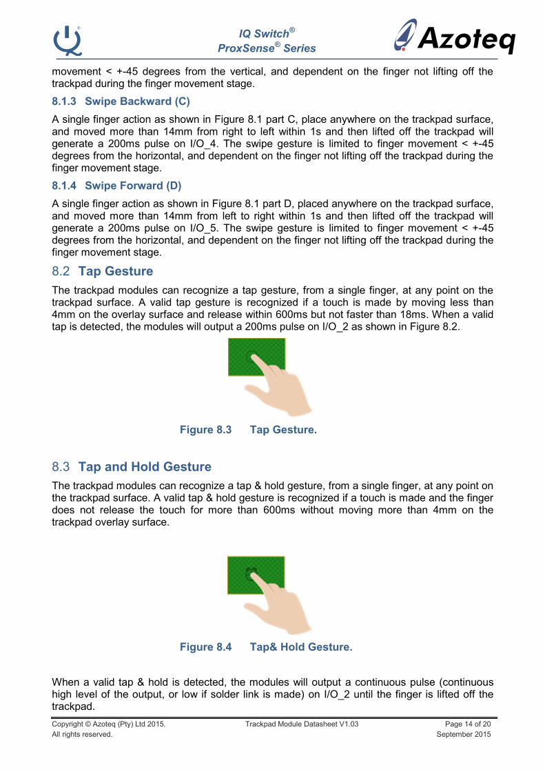
Tap Gesture 8.2
The trackpad modules can recognize a tap gesture, from a single finger, at any point on the trackpad surface. A valid tap gesture is recognized if a touch is made by moving less than 4mm on the overlay surface and release within 600ms but not faster than 18ms. When a valid tap is detected, the modules will output a 200ms pulse on I/O_2 as shown in Figure 8.2.
Figure 8.3 Tap Gesture.
Tap and Hold Gesture 8.3
The trackpad modules can recognize a tap & hold gesture, from a single finger, at any point on the trackpad surface. A valid tap & hold gesture is recognized if a touch is made and the finger does not release the touch for more than 600ms without moving more than 4mm on the trackpad overlay surface.
Figure 8.4 Tap& Hold Gesture.
When a valid tap & hold is detected, the modules will output a continuous pulse (continuous high level of the output, or low if solder link is made) on I/O_2 until the finger is lifted off the trackpad.

IQ Switch®
ProxSense® Series
Copyright © Azoteq (Pty) Ltd 2015. Trackpad Module Datasheet V1.03 Page 15 of 20
All rights reserved. September 2015
200ms 200ms
VDDHI
0V
Figure 8.5 Continuous output of 200ms pulses for swipe and hold gesture.
Swipe and Hold Gestures 8.4
There are four swipe & hold gestures that can be detected by the trackpad modules, as shown in Figure 8.6 below.
Figure 8.6 Illustrations off the 4 swipe & hold gestures that can be detected by the trackpad modules.
Each time any of the swipe & hold gestures are performed correctly, the corresponding I/O pin of the trackpad will continuously output 200ms pulses to the Bluetooth IC. The user has the option to select a high (default) or low (by adding a solder link on the module) pulse. The high level as indicated on the figure below will correspond to the input voltage supplied to the trackpad module.
8.4.2 Swipe Upward & Hold (A)
A single finger action as shown in Figure 8.6 part A, placed anywhere on the trackpad surface, and moved more than 14mm from the bottom to the top within 1s and then kept stationary on the trackpad for 600ms or more will generate continuous 200ms pulses on I/O_1. The swipe gesture is limited to < +-45 degrees from the vertical, and dependent on the finger not lifting off the trackpad during the finger movement stage. The output pulses will stop once the finger is lifted off the trackpad.

IQ Switch®
ProxSense® Series
Copyright © Azoteq (Pty) Ltd 2015. Trackpad Module Datasheet V1.03 Page 16 of 20
All rights reserved. September 2015
8.4.3 Swipe Downward & Hold (B)
A single finger action as shown in Figure 8.6 part B, placed anywhere on the trackpad surface, and moved more than 14mm from the top to the bottom within 1s and then kept stationary on the trackpad for 600ms or more will generate continuous 200ms pulses on I/O_3. The swipe gesture is limited to < +-45 degrees from the vertical, and dependent on the finger not lifting off the trackpad during the finger movement stage. The output pulses will stop once the finger is lifted off the trackpad.
8.4.4 Swipe Backward & Hold (C)
A single finger action as shown in Figure 8.6 part C, placed anywhere on the trackpad surface, and moved more than 14mm from right to left within and then kept stationary on the trackpad for 600ms or more will generate continuous 200ms pulses on I/O_4. The swipe gesture is limited to < +-45 degrees from the vertical, and dependent on the finger not lifting off the trackpad during the finger movement stage. The output pulses will stop once the finger is lifted off the trackpad.
8.4.5 Swipe Forward & Hold (D)
A single finger action as shown in Figure 8.6 part D, place anywhere on the trackpad surface, and moved more than 14mm from left to right within 1s and then kept stationary on the trackpad for 600ms or more will generate continuous 200ms pulses on I/O_5. The swipe gesture is limited to < +-45 degrees from the vertical, and dependent on the finger not lifting off the trackpad during the finger movement stage. The output pulses will stop once the finger is lifted off the trackpad.
Gesture I/O Mapping 8.5
The pin mapping for the modules for gesture output is shown in below.
Table 8.1 Module Gesture Output Pin Mapping.
Gesture Output Pin Output Type Typical Feature
Swipe Upward I/O_1 Single Pulse Volume Increase
Swipe Upward & Hold I/O_1 Multiple Pulses Continuous Volume Increase
Swipe Downward I/O_3 Single Pulse Volume Decrease
Swipe Downward & Hold I/O_3 Multiple Pulses Continuous Volume Decrease
Swipe Forward I/O_5 Single Pulse Skip / Next Track
Swipe Forward & Hold I/O_5 Multiple Pulses Fast Forward
Swipe Backward I/O_4 Single Pulse Skip / Previous Track
Swipe Backward & Hold I/O_4 Multiple Pulses Reverse/Rewind
Tap I/O_2 Single Pulse Play/Pause (Call Answer)
Tap & Hold I/O_2 Continuous Pulse Start/STOP
IQ Switch®
ProxSense® Series
Copyright © Azoteq (Pty) Ltd 2015. Trackpad Module Datasheet V1.03 Page 17 of 20
All rights reserved. September 2015
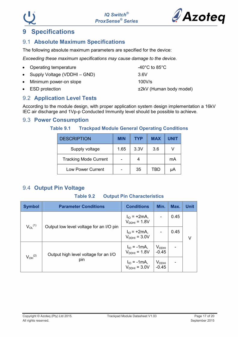
9 Specifications
Absolute Maximum Specifications 9.1
The following absolute maximum parameters are specified for the device:
Exceeding these maximum specifications may cause damage to the device.
Operating temperature -40°C to 85°C
Supply Voltage (VDDHI – GND) 3.6V
Minimum power-on slope 100V/s
ESD protection ±2kV (Human body model)
Application Level Tests 9.2
According to the module design, with proper application system design implementation a 16kV IEC air discharge and 1Vp-p Conducted Immunity level should be possible to achieve.
Power Consumption 9.3
Table 9.1 Trackpad Module General Operating Conditions
DESCRIPTION MIN TYP MAX UNIT
Supply voltage 1.65 3.3V 3.6 V
Tracking Mode Current - 4 mA
Low Power Current - 35 TBD μA
Output Pin Voltage 9.4
Table 9.2 Output Pin Characteristics
Symbol Parameter Conditions Conditions Min. Max. Unit
VOL(1) Output low level voltage for an I/O pin
IIO = +2mA, VDDHI = 1.8V
- 0.45
V
IIO = +2mA, VDDHI = 3.0V
- 0.45
VOH(2)
Output high level voltage for an I/O pin
IIO = -1mA, VDDHI = 1.8V
VDDHI -0.45
-
IIO = -1mA, VDDHI = 3.0V
VDDHI -0.45
-

IQ Switch®
ProxSense® Series
Copyright © Azoteq (Pty) Ltd 2015. Trackpad Module Datasheet V1.03 Page 18 of 20
All rights reserved. September 2015
Table 9.3 Start-up and shut-down slope Characteristics
DESCRIPTION Conditions PARAMETER MIN MAX UNIT
Power On Reset VDDHI Slope ≥ 100V/s
@25°C VPOR 1.44 1.65 V
Power Down Reset VDDHI Slope ≥ 100V/s
@25°C VPDR 1.30 1.60 V

IQ Switch®
ProxSense® Series
Copyright © Azoteq (Pty) Ltd 2015. Trackpad Module Datasheet V1.03 Page 19 of 20
All rights reserved. September 2015
10 Ordering Information
Order quantities will be subject to MOQ of 5k pcs. Contact the official distributor for sample
quantities. A list of the distributors can be found under the “Distributors” section of
www.azoteq.com.
Stand Alone Track Pads 10.1
TP x yy - vhss
Shape Indicator
Size IndicatorHW Revision
SW Revision
Price Range
Trackpad Module TP = Trackpad
Shape Indicator (x) R = Round E = Ellipsoid S = Square/Rectangular
Size Indicator (yy) 40 = 40mm
48 = 48mm
54 = 54mm
60 = 60mm
Price Range (v) V = Value Line (low cost) P = Performance Line (high performance)
Hardware Revision (h) 1 = Standard BT Headphone Module Software Revision (ss) 01 = Standard Gestures
Example: TPR40-P101 – is a round 40mm trackpad from the high performance line, 1st revision HW and SW
Note: For non-standard versions please contact Azoteq direct.

IQ Switch®
ProxSense® Series
Copyright © Azoteq (Pty) Ltd 2015. Trackpad Module Datasheet V1.03 Page 20 of 20
All rights reserved. September 2015
Appendix A. Contact Information
USA Asia South Africa
Physical
Address
6507 Jester Blvd Bldg 5, suite 510G Austin TX 78750 USA
Rm2125, Glittery City
Shennan Rd
Futian District
Shenzhen, 518033
China
109 Main Street
Paarl
7646
South Africa
Postal
Address
6507 Jester Blvd Bldg 5, suite 510G Austin TX 78750 USA
Rm2125, Glittery City
Shennan Rd
Futian District
Shenzhen, 518033
China
PO Box 3534
Paarl
7620
South Africa
Tel +1 512 538 1995 +86 755 8303 5294
ext 808
+27 21 863 0033
Fax +1 512 672 8442 +27 21 863 1512
Email [email protected] [email protected] [email protected]
Please visit www.azoteq.com for a list of distributors and worldwide representation.
The following patents relate to the device or usage of the device: US 6,249,089 B1; US 6,621,225 B2; US 6,650,066 B2;
US 6,952,084 B2; US 6,984,900 B1; US 7,084,526 B2; US 7,084,531 B2; US 7,265,494 B2; US 7,291,940 B2; US 7,329,970 B2;
US 7,336,037 B2; US 7,443,101 B2; US 7,466,040 B2 ; US 7,498,749 B2; US 7,528,508 B2; US 7,755,219 B2; US 7,772,781
B2; US 7,781,980 B2; US 7,915,765 B2; US 7,994,726 B2; US 8,035,623 B2; US RE43,606 E; US 8,288,952 B2; US 8,395,395
B2; US 8,531,120 B2; US 8,659,306 B2; US 8,823,273 B2 B2; EP 1 120 018 B2; EP 1 206 168 B1; EP 1 308 913 B1; EP 1 530
178 A1; EP 2 351 220 B1; EP 2 559 164 B1; CN 1330853; CN 1783573; AUS 761094; HK 104 1401
IQ Switch®, SwipeSwitch™, ProxSense
®, LightSense™, AirButton
TM and the logo are trademarks of Azoteq.
The information in this Datasheet is believed to be accurate at the time of publication. Azoteq uses reasonable effort to maintain the information up-to-date and accurate, but does not warrant the accuracy, completeness or reliability of the information contained herein. All content and information are provided on an “as is” basis only, without any representations or warranties, express
or implied, of any kind, including representations about the suitability of these products or information for any purpose. Azoteq disclaims all warranties and conditions with regard to these products and information, including but not limited to all implied warranties and conditions of merchantability, fitness for a particular purpose, title and non-infringement of any third party
intellectual property rights. Azoteq assumes no liability for any damages or injury arising from any use of the information or the product or caused by, without limitation, failure of performance, error, omission, interruption, defect, delay in operation or transmission, even if Azoteq has been advised of the possibility of such damages. The applications mentioned herein are used solely
for the purpose of illustration and Azoteq makes no warranty or representation that such applications will be suitable without further modification, nor recommends the use of its products for application that may present a risk to human life due to malfunction or otherwise. Azoteq products are not authorized for use as critical components in life support devices or systems. No licenses to patents are granted, implicitly, express or implied, by estoppel or otherwise, under any intellectual property rights. In the event that any of the abovementioned limitations or
exclusions does not apply, it is agreed that Azoteq’s total liability for all losses, damages and causes of action (in contract, tort (including without limitation, negligence) or otherwise) will not exceed the amount already paid by the customer for the products. Azoteq reserves the right to alter its products, to make corrections, deletions, modifications, enhancements, improvements
and other changes to the content and information, its products, programs and services at any time or to move or discontinue any contents, products, programs or services without prior notification. For the most up-to-date information and binding Terms and Conditions please refer to www.azoteq.com.
WWW.AZOTEQ.COM

Mouser Electronics
Authorized Distributor
Click to View Pricing, Inventory, Delivery & Lifecycle Information: Azoteq:
TPE60-P101 TPE48-P101 TPR54-P101 TPR40-P101 TPR48-P101 TPS48-P101