Embed Size (px)
Citation preview

IAEA-TECDOC-930
Generic componentreliability data
for research reactor PSA
INTERNATIONAL ATOMIC ENERGY AGENCY /A\

The IAEA does not normally maintain stocks of reports in this series.However, microfiche copies of these reports can be obtained from
INIS ClearinghouseInternational Atomic Energy AgencyWagramerstrasse 5P.O. Box 100A-1400 Vienna, Austria
Orders should be accompanied by prepayment of Austrian Schillings 100,in the form of a cheque or in the form of IAEA microfiche service couponswhich may be ordered separately from the INIS Clearinghouse.

The originating Section of this publication in the IAEA was:
Safety Assessment SectionInternational Atomic Energy Agency
Wagramerstrasse 5P.O. Box 100
A-1400 Vienna, Austria
GENERIC COMPONENT RELIABILITY DATAFOR RESEARCH REACTOR PSA
IAEA, VIENNA, 1997IAEA-TECDOC-930
ISSN 1011-4289
©IAEA, 1997
Printed by the IAEA in AustriaFebruary 1997

FOREWORD
Probabilistic safety assessments (PSAs) are increasingly used for safety evaluation of researchreactors. PSA methodology and approaches for research reactors are in general similar to those usedfor power reactors. However, there are some significant differences. The main differences arerelated to the set of data to be used for quantifying the models.
As component reliability data for research reactors was not available in 1988, the IAEA initiateda co-ordinated research programme on data acquisition for research reactors. The aim of theprogramme was to develop rules and procedures for data collection (published as IAEA-TECDOC-636) and to conduct a data collection exercise on thirteen reactor facilities in ten participatingcountries.
The programme lasted for four years. The data collection exercise resulted in a databasecontaining reliability parameters for more than one thousand research reactor components. All thedata is based on the operating experience of participating reactors. The database was compiled duringthe final research co-ordination meeting held in Chalk River, Canada, in 1993.
The report was written by contributors from Austria, Canada and Switzerland and theproduction was co-ordinated by B. Tomic of the Safety Assessment Section of the Division of NuclearSafety. It includes data supplied by all the participants in the co-ordinated research programme.

EDITORIAL NOTE
In preparing this publication for press, staff of the IAEA have made up the pages from theoriginal manuscript(s). The views expressed do not necessarily reflect those of the governments ofthe nominating Member States or of the nominating organizations.
Throughout the text names of Member States are retained as they were when the text wascompiled.
The use of particular designations of countries or territories does not imply any judgement bythe publisher, the IAEA, as to the legal status of such countries or territories, of their authorities andinstitutions or of the delimitation of their boundaries.
The mention of names of specific companies or products (whether or not indicated as registered)does not imply any intention to infringe proprietary rights, nor should it be construed as anendorsement or recommendation on the part of the IAEA.

CONTENTS
1. INTRODUCTION . . . . . . . . . . . . . . . . . . . . . . . . . . . . . . . . . . . . . . . . . . . . 7
1.1. Background . . . . . . . . . . . . . . . . . . . . . . . . . . . . . . . . . . . . . . . . . . . . . . 71.2. Purpose . . . . . . . . . . . . . . . . . . . . . . . . . . . . . . . . . . . . . . . . . . . . . . . . 8
2. REACTOR FACILITIES AND DATA COLLECTION METHOD . . . . . . . . . . . . . . . 8
3. INSIGHTS FROM THE DATA COLLECTION PROCESS . . . . . . . . . . . . . . . . . . . 9
4. USE OF THE DATABASE . . . . . . . . . . . . . . . . . . . . . . . . . . . . . . . . . . . . . . . 9
4.1. Location of component reliability data . . . . . . . . . . . . . . . . . . . . . . . . . . . . . 94.2. Accuracy of reliability data . . . . . . . . . . . . . . . . . . . . . . . . . . . . . . . . . . . . 10
4.2.1. Data collection and processing . . . . . . . . . . . . . . . . . . . . . . . . . . . . . 104.2.2. Component reliability . . . . . . . . . . . . . . . . . . . . . . . . . . . . . . . . . . . 114.2.3. Data selection . . . . . . . . . . . . . . . . . . . . . . . . . . . . . . . . . . . . . . . 12
4.3. Reliability data on common cause failure . . . . . . . . . . . . . . . . . . . . . . . . . . . . 134.4. Uncertainty bounds . . . . . . . . . . . . . . . . . . . . . . . . . . . . . . . . . . . . . . . . . 13
TABLES
Table I. Alphabetical list of component groups and associated codes . . . . . . . . . . . . . . 15Table II. Component type descriptions and associated codes . . . . . . . . . . . . . . . . . . . . 19Table III. Failure mode code definitions . . . . . . . . . . . . . . . . . . . . . . . . . . . . . . . . . 27Table IV. Features of the contributing research reactor facilities and data collection
process . . . . . . . . . . . . . . . . . . . . . . . . . . . . . . . . . . . . . . . . . . . . . . 29Table V. Overview of component types and populations documented for each facility . . . . 31Table VI. Specific information on component types for each facility . . . . . . . . . . . . . . . 41Table VII. Component reliability database . . . . . . . . . . . . . . . . . . . . . . . . . . . . . . . . 53
REFERENCES . . . . . . . . . . . . . . . . . . . . . . . . . . . . . . . . . . . . . . . . . . . . . . . . 69
CONTRIBUTORS TO DRAFTING AND REVIEW . . . . . . . . . . . . . . . . . . . . . . . . . . 71

1. INTRODUCTION
Information on reliability data for research reactor components was not readily available in theliterature in 1988. Similar information for power reactors is widely available for most power reactortypes, either on a commercial basis or from open literature sources [1-3]. Component reliability datasources for power reactors should provide the best alternative source of relevant data, in the absenceof either site-specific or generic research reactor data. The use of component reliability data forpower reactors, as an alternative to site-specific or generic research reactor data, does however havetwo basic disadvantages. Firstly, design and operational differences in many power reactorcomponents make comparisons difficult. The result is increased uncertainty in the application of ageneric reliability data source for power reactors to a specific research reactor application due todifferences in component type, size and application. Secondly, there are numerous research reactorcomponents that have no counterpart in power reactors.
To overcome the problem of data availability, the IAEA initiated a Co-ordinated ResearchProgramme (CRP) on Data Acquisition for Probabilistic Safety Analysis (PSA) Studies for ResearchReactors, aimed at providing the necessary generic component reliability database. The database,used by most CRP participants, was generated using the DES Data Entry System [4]. The CRPparticipant from ANSTO developed this system for use in conjunction with the data collectionprocess. DES was made available to other participants for data collection and is available from theIAEA for use as a reliability database. The report provides the user with the generic componentreliability database in a summarized spreadsheet format.
While this report focuses primarily on the needs of research reactor PSA, the genericcomponent database also provides a useful reference source of reliability data for other researchreactor applications. For example, typical applications would be the comparison of generic datasources for other research reactor types for the purposes of producing annual reactor operating reviewreports, or for updating reactor safety analysis reports. This type of comparison may assist inproviding useful information about both systems and component operation, in light of internationalexperience with similar research reactor types and equipment. For example, fuel failure rate data orregulating system failure rate comparisons could provide valuable input into research reactorupgrades/deterministic safety analysis programmes in order to supplement the decision making processfor potential design and/or operational changes.
Ideally, failure data used for safety and reliability analyses should be based on site-specific data.However, the production of accurate site-specific data requires the expenditure of considerableresources to develop and maintain an extensive database. The collection of database sourceinformation from the field — i.e. from reactor maintenance and/or operations reports — requires asystematic approach and an ongoing commitment, if the information is to be processed efficiently andif it is to be kept up to date. In addition to the need for operational and maintenance staff to provideraw data input, a software system and analytical personnel to process the raw data are also required.The data processing primarily produces component-reliability-parameter statistics and trend analysisdata. The reliability parameter data is often formatted so that information can interface directly withPSA studies. For example, component failure rate data may be linked to a PSA-specific basic eventlabelling format. The use of generic data by itself will not provide an adequate data source to aid intrend analysis of site-specific system equipment. Generic data can still, however, indicate whetherthere may be site-specific features or site-specific equipment problems that may be considerablydifferent from that which might be predicted from international generic sources of other researchreactors. The component reliability data in this report is applicable across a broad range of researchreactor types and sizes.
1.1. BACKGROUND
During 1986-1988 the IAEA undertook a Co-ordinated Research Programme (CRP) on PSAfor research reactors which helped to promote and foster an international exchange of information

between national institutes and universities on the subject [5, 6]. During this period, extensivesystematic PSA studies on research reactors were also being both contemplated for the first time andinitiated. The need for development of a research reactor component reliability database wasidentified from the research reactor PSA CRP work. This resulted in the setting up of the researchreactor data acquisition CRP. The application of PSA and the subsequent relevant databasedevelopment on research reactors followed similar developments for power reactors [1].
The current document was prepared using the framework of the data acquisition CRP. It isbased on the first meeting of the CRP held in Vienna in October 1989. A second meeting was heldin Beijing, China, in October 1990 and the final meeting was held in Chalk River, Canada in July1993. The report was completed in Vienna in December 1993. All members of the CRP contributedcomponent reliability data to the final database.
The CRP project officer was B. Tomic from the IAEA's Safety Assessment Section of theDivision of Nuclear Safety. Following the Beijing meeting, IAEA-TECDOC-636 was produced [7].This document provided the definition of terms to be used in the component data collection, derivedspecifically to cover research reactors. It also contains all the definitions necessary to classifyresearch reactor equipment, and to identify and group individual component boundary and componentfailure type definitions. Relevant reliability parameters are also defined and the method of calculationis shown in Ref. [7]. The various definitions are not repeated in the current report since Ref. [7] isintended to be a supporting document for the user of the database. An updated version of thecomponent group listing, the breakdown of component groups into component types, and theassociated coding is provided in Tables I and II. The failure mode code definitions of Ref. [7] arelisted in Table III.
1.2. PURPOSE
The purpose of this document is to supplement the information in Ref. [7] and to providereference generic component-reliability information for a variety of research reactor types. As notedin Section 2 and Table IV, component data accumulated over many years is in the database. It isexpected that the report should provide representative data which will remain valid for a number ofyears. The database provides component failure rates on a time and/or demand related basisaccording to the operational modes of the components.
No update of the database is presently planned. As a result of the implementation of datacollection systems in the research reactors represented in these studies, updating of data fromindividual facilities could be made available by the contributing research reactor facilities themselves.
As noted in Section 1.1, the report does not include a detailed discussion of informationregarding component classification and reliability parameter definitions, which is provided in Ref. [7].The report does provide some insights and discussions regarding the practicalities of the datacollection process and some guidelines for database usage.
2. REACTOR FACILITIES AND DATA COLLECTION METHOD
A total of 12 research reactors from 9 participating countries are represented within the CRP.Failure data on components have been submitted from each of these facilities. The data collectionperiod varied according to the facility, ranging from 2 to 28 years. Reactor-power ratings variedfrom 100 kW(th) to 135 MW(th). The number of components monitored varied from fewer than 20to about 10 000 per facility. Essentially all participants used component definitions from Ref. [7].The raw data sources were reactor log books, maintenance records and other documented operationalexperience. A compilation of the various general features of the reactor facility types and data issummarized in Table IV.

At the start of this programme no formal system for recording component reliability data wasin place in most facilities. After 1986 the initiation of PSA studies at most of these facilities providedan impetus for the development of a component reliability database. The database systems in thecontributing facilities are subsequently being maintained on a continuing basis for the purpose of long-term trend and equipment monitoring.
As noted in Section 1, the DES data entry system [4], was used by a number of participants toinput and record raw data. The component database for this report has been compiled from the DESoutput information provided by the participants. It is represented in an easy-to-use spreadsheet formatin Table VII. A description of the procedure for extracting reliability data from Table VII is providedin Section 4.
A wide variety of component types are referenced in the database coding system. Data isavailable on most component types. Coding for component types without data is maintained, forreference purposes, to allow for future additions to the database. In general, the data emphasizesmajor component types and failure rates which are dominated by top-event failure frequencies fromPSA studies. Most of these components are of the active type (i.e. they rotate or move), althoughpassive components (i.e. such as the reactor vessel and transformers) are also included.
The systems represented by the majority of the components are listed for each facility inTable IV. In general these are the most important safety systems, safety-related systems and keyprocess systems that are most commonly analyzed in PS As. The typical function and descriptions ofthese systems are provided in Ref. [8].
3. INSIGHTS FROM THE DATA COLLECTION PROCESS
The collection of component reliability data is invariably a tedious task unless a system is inplace to perform this on a continuous long-term basis. This was rarely the case until relativelyrecently for research reactor facilities. By contrast, many power reactors have had formalizedcollection systems for component reliability data for many years. The lack of staff resources atresearch reactor facilities is one of the main reasons for the absence of a formal system. Anotherfrequent difficulty is the lack of a computerized system for documenting maintenance and operatingrecords. This means that the collection of field data from a variety of hard copy recording systemsis time consuming. The quality of failure information also varies; it is primarily determined by theskill of maintenance and operations staff and how useful this type of information is regarded byreactor staff.
The features noted above are also not uncommon for non-nuclear process plants. Many of thecontributing facilities utilized students for data collection and analysis.
After the data collection and analysis process, very useful feedback was received on operationsand performance of equipment maintenance which led to improvements on equipment test andmaintenance procedures and in the failure record keeping process. Identification of potential incipientfailures and the trend of decreasing component reliability were other benefits obtained from theprocess. Generally, only when maintenance and operations staff can see direct usefulness of areliability data system will improvements be made in the quality of inputting field data.
4. USE OF THE DATABASE
4.1. LOCATION OF COMPONENT RELIABILITY DATA
This section describes the process for use of the reliability database. To locate a specificcomponent in the database, Table I should first be consulted. This list provides an alphabetic orderingby description/name of the different component groups. These component groups are defined ascomponents of a given general component category (Table II column 1) e.g. sensors, which have

different functions (e.g. flow sensors, level sensors). Having identified the two letter componentgroup coding from Table I column 1, Table II is then consulted to locate the description of the closestmatch for a desired component. Table II, column 6 provides a component type listing which givesthe highest level of description for a component. For example, different types of pressure sensorsmay be identified. The component type coding is a three letter code, given in Table II, column 5.Table II provides a complete listing of the component category, group and type descriptions, andcodes in alphabetical order of the component type code. Table II is utilized by first locating thedesired two letter component group code, provided in alphabetic ordering in column 3, and thenreviewing the associated list of component types in column 6 until the closest match of a desireddescription is found.
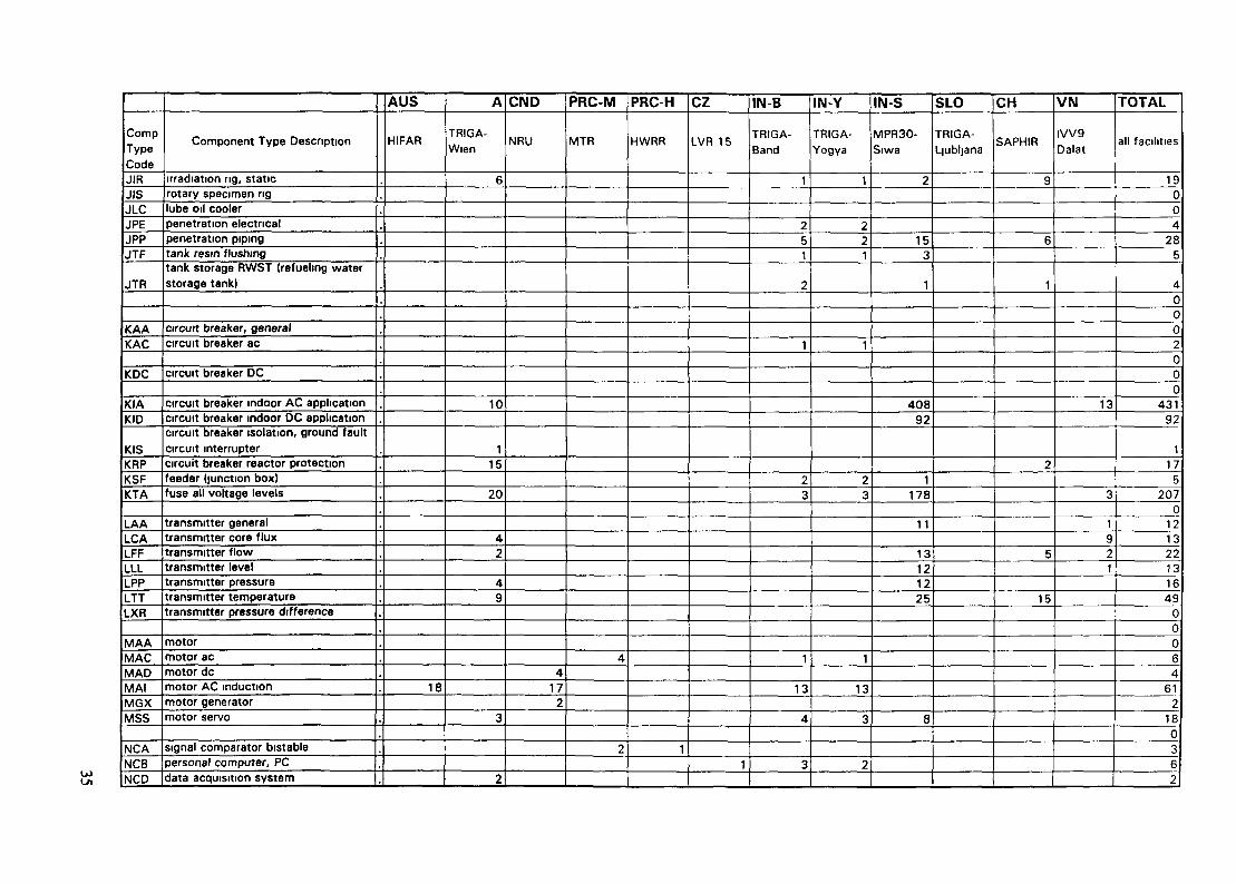
Having identified the most relevant component type by its three letter identification code,Table V can then be used to provide an overview of the number of facilities which have recorded dataon that component type. Table V also provides the relevant component type populations for eachcontributing facility. Table VI summarizes information on component types including manufacturer'sinformation for each contributing facility. The table is presented per facility. A three-character codesimilar to that used in Table V is associated with each component type. To locate the specificreliability data available for the identified component type, Table VII is used.
Table VII, column 1 lists the three-letter component type codes alphabetically. Having locatedthe component type code, the available data on that component for each facility can then be found.The legend for Table VII provides the necessary explanations for each of the columns. The two basicparameters: failure rate and failure per demand, with associated 90% confidence bounds, areprovided. The raw data on component population, operating or calendar time, number of failures ordemands are provided for the user as a check on the extent of the raw data.
4.2. ACCURACY OF RELIABILITY DATA
In addition to statistical uncertainty, discussed in Section 4.4, there are a number of causeswhich contribute to the inaccuracy of reliability data. Those causes influence both generic andfacility-specific data. The following sections discuss the various causes.
The causes of differences in reliability data can be grouped in two areas, namely:
differences in data collection or data processing;the actual component reliability is different.
In each of these areas a number of individual factors influencing reliability parameters has beenidentified. A short discussion of the most important factors is given below. Also, a discussion on dataselection is included.
4.2.1. Data collection and processing
The inaccuracy in reliability data caused by data collection or data processing can be significant.Factors related to the following are discussed here:
data sources;the ways the data is collected;data processing;definitions.
Data sources
The raw data is collected from historical records — i.e. log books, maintenance work recordsand test records. While the log books are generally considered to be the most accurate, a number offailures, especially on non-safety equipment, may not have been recorded. However, collecting datafrom the log books is extremely time consuming. Maintenance work orders are considered to be the
10

most complete records, but the reliability of the information depends on the person completing thereport. In many cases these are maintenance staff themselves, therefore the accuracy of the records(usually not computerized in research reactor facilities) varies. The direct consequence of incompleterecords is usually an overestimation of component reliability. Therefore the reliability data may bebiased.
Events without work request
Sometimes, relatively minor failures (such as mis-positioned valves) are reported during a testwithout a work request having been prepared. One example is a valve that opens only on second trialduring a test (or after a small, local repair). Only a comment on a test sheet is written. There is noformal work order or any other documented evidence. Since some of the failures are not accountedfor, reliability could be overestimated.
Failure of supporting equipment
Equipment failures may often be directly related to the failure of auxiliary equipment, supportor control systems. Such failures, although effectively disabling the component, are not failures ofthe component. Some databases do not separate such failures. Since supporting equipment failurescould actually dominate overall failure rate, this can cause substantial inaccuracy in the reportedfailure rate.
Coding errors
Coding errors are a classic problem encountered in every data collection exercise. Codingerrors are present in both computerized and manual data collection, and are generally related todiffering interpretations of criteria.
Failure rate denominators
The number of failures collected from the log books or maintenance/testing sheets are only oneinput used for the failure rate calculation. The number of demands, the failure exposure time or thecomponent's running time, are also essential. In the standard failure rate calculation, the denominatoris a quantitative measure of the stress that the component was subject to, related to a specific type offailure which may occur (failure mode).
The way the failure rate denominators are determined may produce a sizeable inaccuracy in acomponent's calculated failure rate. For equipment usually in standby mode, the data sourcesavailable today provide separate data on failures to start and failures to run (and sometimes on otherfailure modes such as leakage/rupture). The denominator for failures to run is a component's actualrunning time, which is usually estimated (e.g. 1 hour per test) and sometimes recorded.
4.2.2. Component reliability
Component reliability is a function of its design, use and maintenance. Components designedfor specific research reactor application (especially safety related) are usually highly reliable andshould be maintained as such during their lifetime. The reliability data, however, often showvariations which are related to operating conditions and practices, component application andmaintenance, and testing practices. A brief discussion of the influence of each of these is givenbelow.
Operating conditions and practices
A facility's operating conditions and practices may greatly influence component reliability.Some of the influence factors are:
11
operating mode;operating time and demands;operating environment.
The operating mode has been recognized as influencing equipment reliability, especially onactive components (such as pumps). Some data sources provide separate data for running, alternatingand standby categories. In the IAEA survey [9], variations of more than two orders of magnitudehave been documented for the failure to run of motor-operated pumps when comparing betweenalternating pumps, running pumps and pumps where no mode has been specified. This findingsupports the view that failure data for similar equipment having differing operating modes should bekept separate.
A component's failure to start may be caused by a demand related stress (e.g. vibration), orstress in standby (e.g. corrosion) or a combination of both. Most data sources disregard thesedifferences and provide data on failure to start either as demand related or time related. When timerelated data are provided, the failure rate denomination is usually calendar time, or sometimes plantoperating time. Since similar components at a different location may have a substantially differenttest interval, the actual number of demands in a period may vary, which in turn may greatly influencethe failure rate. Some data collection systems also systematically collect information on the numberof demands; in others the number of demands is estimated on the basis of testing demands owing tothe costs of collecting the information.
Operating conditions may also influence component reliability. Examples of this would beambient temperature, humidity, chemical control, radiation fields and vibration.
Design and application
Design and application of a component will have an important influence on reliability. Theapplication of the component will determine the operating mode and environment. Variations due tothese causes has been discussed in previous sections.
Maintenance and testing practices
Significant plant-to-plant variations for otherwise identical components can be identified. Thesevariations are most probably caused by facility-specific maintenance and testing differences. Theinfluence of the testing interval and practice has been extensively investigated. The testing intervalhas an influence on the failure rate, but it is strongly related to component type. The testing intervalhas greater influence on components where standby stresses dominate failure probability (usuallymotor operated valves) and lower on components with higher demand stresses (such as dieselgenerators and similar).
4.2.3. Data selection
As discussed, a number of factors may influence reliability data. Although it is difficult toquantify these, an order-of-magnitude estimate could be made.
The overall effect of the factors noted below can therefore substantially influence the results.
Since there is the possibility of a considerable variation in reliability data between differentfacilities, facility-specific data is the best possible source. However, when this data is sparse, otherdata sources must be used. In this case, their compatibility and applicability should be carefullyassessed.
12

ESTIMATE OF RELIABILITY DATA ACCURACY WITH VARIOUS CAUSES OF VARIABILITY
Variability factor Estimated accuracy
Collection related (comprehensiveness)Failure severity/failure modeDemand/operation attributesFailures in shut down taken into accountNon-representative samplesCollection of denominatorsSite effects (testing, maintenance)
2 to 5< 2< 222 to 102 to 52 to 10
When adopting reliability data from a data source, the definitions and their compatibility arefirst assessed. The background of a data source, including the ultimate data source,comprehensiveness of the data collection and data processing methods should be considered next.Finally, for reliability data originating at a research reactor, design (including age of design),operation, testing and maintenance practice should be examined for compatibility.
Although even the most careful data selection would not fully exclude the possibility of adoptingincompatible data, the fact that the factors contributing to data accuracy have been recognized shouldensure that the choice of data is reasonable.
4.3. RELIABILITY DATA ON COMMON CAUSE FAILURE
Quantification of common cause failure (CCF) data, in particular for system designs withredundant components, is an important aspect of PSA studies. CCF is also one of the most difficultareas in principle and in practice to obtain data. Collecting and reporting CCF data is a special aspectof reliability data collection. It is beyond the scope of this report to provide quantified data regardingcomponent CCFs, as defined in Ref. [7], Section 5.2.5. Therefore CCF specific data are not includedhere. To provide this type of data requires a detailed review of individual failure events. The failuredata provided by participants may include some common cause events. Experience with generic CCFdata has shown that it is very unlikely that the common cause contribution is a significant percentageof the recorded failure events. It can therefore reasonably be assumed that data uncertainties due tocommon cause failures are negligible compared with statistical uncertainties, Section 4.4, and theother contributing sources of inaccuracy, Section 4.2, in the data.
4.4. UNCERTAINTY BOUNDS
Following accepted practice in most databases, statistical uncertainty is calculated as discussedin Ref. [7], Appendix D. The 90% confidence range with 5% and 95% limits around the mean valueis defined. As noted in Ref. [7], failure rates and failures per demand utilize different expressionsfor the uncertainty calculations, although the differences between the calculations are not large. Thespreadsheet software EXCEL, version 4.0A, used for the production of the Table VII database,provided the necessary chi-square and F function variables needed for the uncertainty calculation.
The uncertainty bound values for the failure rates are provided in the last columns of Table VII.Note that the uncertainty bounds associated with a demand failure are in dimensionless units. Forcases with zero failure the numerator is set to 0.693 (taken from the 50% chi-squared value for onefailure) for the entry in the "failure rate" column of Table VII and a zero value is entered into the"5%" sub-column of the "90% confidence bounds" column. In all other cases the entry in "failurerate" column is the mean failure rate.
NEXT PAQE(S) I«•ft BLANK § 13

TABLE I. ALPHABETICAL LIST OF COMPONENT GROUPS AND ASSOCIATED CODES
The following list provides component groups in alphabetical order with the associatedcomponent group coding. The group coding consists of two capital letters: the first describes themain component type category, the second describes the component group.
15

Component Group Code
QAYAUNBTBCGBQBCBCCKAKDKl
KCKRJEQCNKNCOCORUCECHCJCQDDEDGEXQFKSYFXTXHXLXMXPXCXAKTDTFYHXEHQVUlNOIA1CIDNIElJlJLTEUMMAMGMSFXEB
Component Group Description
Air coolerAir filterAnnunciatorBatteryBattery chargerBeam ports, beam tubesBlower fanBusCableCircuit breakerCircuit breaker DCCircuit breaker indoorCircuit breaker molded typeCircuit breaker, high reliabilityClutchCompressorComputational moduleComputerControl rodControl rod driveControllerConverterCooling towerCore structureDamperDiesel engineDiesel generator emergency ACElectrical equipment for experimentsFan cooler, containmentFeeder (branch, junction)FilterFlux shaping elementFuel element HEUFuel element LEUFuel element MEUFuel element process tubesFuel element handling toolFuel, generalFuseGas turbine driven generator emergency ACGasketHeat exchangerHeater electricHVAC unit annulus ventilationIndicating instrumentInput/output deviceInstrumentationInstrumentation channel analogInstrumentation channel digitalInterfaceInverterIrradiation facilitiesLube oil coolerMain facility transformerManual control deviceMotorMotor generatorMotor servoOrificePanelboard
16

Component Group Code
JPFEFNFSFTFWGPEPNDNPPDPMPTPWARURERXRXB
RWRARYRXRCRPRRRTFRACAFAAALAPASATAQWAWFWXNSNMUEGSYSSCSDSFSLSI
SMSPSTSQSAJTGTTATTTlTV
Component Group Description
Penetration containmentPiping expansion jointPiping nozzlePiping straight sectionPiping teesPiping weldsPool, open swimming poolPower supplyPrinterProgramable logic controllerPump diesel drivenPump motor drivenPump turbine drivenPump without driverRadiation monitorsReactor scram systemRectifierReflector element, graphiteReflector, BerylliumRelayRelay auxiliaryRelay coilRelay contactsRelay controlRelay powerRelay protectiveRelay time delayRupture diaphragmSensor core fluxSensor flowSensor generalSensor levelSensor pressureSensor speedSensor temperatureSensor water chemistryShielding generalShielding irradiated fuelShielding of experimentsSignal conditioning systemSignal modifierSolid state deviceStorage containersStrainerSwitch contactsSwitch digital channelSwitch flowSwitch levelSwitch limitSwitch manualSwitch pressureSwitch temperatureSwitch torqueSwitch, generalTankTank, closed vesselTransformerTransformer autoTransformer instrumentationTransformer regulating
17

Component Group Code
TXTULCLFLALLLPLTVAVEVHVXVMVPVCVDVWCW
Component Group Description
Transformer for main facility supplyTransformer substationTransmitter core fluxTransmitter flowTransmitter generalTransmitter levelTransmitter pressureTransmitter temperatureValve air operatedValve explosive operatedValve hydraulic operatedValve manualValve motor operatedValve piston operatedValve self operatedValve solenoid operatedValve without operatorWire
18

TABLE II. COMPONENT TYPE DESCRIPTIONS AND ASSOCIATED CODES
This table gives a description of each component category, group and type, in alphabeticalorder, of the three letter coding system. To find a specific component type, Table I may first haveto be consulted as it provides the component group listing in alphabetical order. The coding systemis based, to a large extent, on that formulated in Ref. [l].
19

<UT3OO
A
B
C
D
E
Component CategoryDescription
Sensors
Batteries and chargers
Conductors
Diesel generators, gasturbine driven generators
Other electricalequipment, electrical partof experimentalinstallations
<o73OO
AAAC
AF
AL
AQ
AP
AR
ASAT
BC
BT
CB
CC
cw
DE
DG
DT
ES
EC
EH
El
EP
ER
Component Group Description
Sensor generalSensor core flux
Sensor flow
Sensor level
Sensor water chemistry
Sensor pressure
Radiation monitors
Sensor speedSensor temperature
Battery charger
Battery
Bus
Cable
Wire
Diesel engine
Diesel generator emergencyACGas turbine driven generatoremergency AC
Panelboard
Converter
Heater electric
Inverter
Power supply
Rectifier
CD73OO
AAAACÁACIACFACSAFAAHAALAALRAQCAQPAPAAPDARAARGARNAROARUASAATA
BCABCSBTABTLBTN
CB2CB3CB6CBACBDCCPCCSCWACWC
DEA
DGA
EBA
ECM
EHAEHPEHOEHTEHWEIAEliEIXEIZEPA
EPHEPUERS
Component Type Description
Sensor generalSensor core fluxIonisation chamberFission counterSelf powered detectorSensor flowSensor humiditySensor levelSensor pool water levelSensor conductivitySensor pH-valueSensor pressureSensor pressure differenceAerosol monitorgamma monitorneutron monitoroff-gas monitorradiation monitoring alarm unitsensor speedsensor temperature
battery chargerbattery charger solid statebatterybattery lead acid accumulatorbattery nickel cadmium accumulator
bus 120Vac , 220Vac sing, phasebus 220Vac, 380Vac three phasebus 6kVbus general power distrbus DCcable power connectioncable signal (supervisory)wirewire control circuit typical circuit, severaljoints
diesel engine
diesel generator emergency AC
terminal board
static converter for reactor main coolantpumpsair heaterpressunzer heateroil heaterheat tracing pipe heaterwater heaterinverterinverter instrumentinverter static three phaseinverter static single phasepower supply (instrumentation and controlequipment)high voltage p.s. instrumentationuninterruptible p.s. < 1 kVArectifier static
20

a¡•a0U
F
G
H
1
Component CategoryDescription
Piping
Pool, grid plate, beamports, D20-tank, storagecontainers
Heat exchanger
Instrumentation(channels, reactorprotection system)
aT30u
EX
FEFN
FRFS
FTFWFXFY
GB
GP
GS
GT
HCHX
IA
1C
ID
Component Group Description
Electric equipment forexperiments
Piping expansion jointPiping nozzle
Rupture diaphragmPiping straight section
Piping teesPiping weldsOrificeGasket
Beam ports, beam tubes
Pool, open swimming pool
Storage containers
Tank, closed vessel
Cooling towerHeat exchanger
Instrumentation
Instrumentation channelanalog
Instrumentation channeldigital
CO•oouEXA
FEAFNAFNSFRAFS3FSAFSMFSSFTAFWAFXAFYA
GBC
GBRGBTG PLG PSGSFGSHGTAGTDGTE
HCAHXAHXB
HXFHXH
HXM
HXPHXRHXTHXV
IAA
IARICA
ICCICFId-IC?ICSICTIDA
(DCIDFIDLIDPIDT
Component Type Description
Electric equipment for experiments, general
piping expansion jointpiping nozzlepiping nozzle sprayRupture diaphragm, generalpiping medium, 1" < diameter < = 3"piping straight sectionpiping large, > 3" diameterpiping small, < = 1 " diameterpiping teespiping welds, generalorificegasket
thermal column
beam port, radialbeam port, tangentialpool linerstorage rack for fuelstorage and transp cont irrad fuelstorage, fresh fueltank, reactor vesseltank, heavy water containerexpansion tank
cooling tower generalheat exchangerheat exch. straight tube horizontal shell andtubeheat exch. fuel storageheat exch. U tube horizontal shell and tube
heat exch. straight tube vertical shell andtubeheat exch. plate typeheat exch. pond heat removalheat exch. cleaning systemheat exch. U tube vertical shell and tube
instrumentation
control rod position indicationinstr. ch. analog general
instr. ch. analog core fluxinstr. ch. analog flowinstr. ch. analog levelinstr. ch. analog pressureinstr. ch. analog seismicinstr. ch. analog temperatureinstr. ch. digital, general
instr. ch. digital core fluxinstr. ch. digital flowinstr. ch. digital levelinstr. ch. digital pressureinstr. ch. digital temp
21

0)EJ
K
L
M
N
Component CategoryDescription
Other mechanicalequipment, lifting gear,structures, experimentalsetup
Circuit breakers
Transmitters
Motors
Signal conditioningsystem, computers
0)13OO
JC
JE
Jl
JLJP
JT
KA
KCKDKl
KR
KSKT
LALCLFLLLPLT
MA
MGMS
NC
NDNINKNM
Component Group Description
Core structure
0)•o0U
JCA
JCGJCT
clutch IJEE
Irradiation facilities
Lube oil coolerPenetration
Tank
Circuit breaker
Circuit breaker molded typeCircuit breaker DCCircuit breaker indoor
Circuit breaker, high reliability
Feeder (branch, junction)Fuse
Transmitter generalTransmitter core fluxTransmitter flowTransmitter levelTransmitter pressureTransmitter temperature
Motor
Motor generatorMotor servo
Computer
PrinterInterfaceComputational moduleSignal modifier
JEMJIAJIHJIPJIRJISJLCJPE jJPPJTFJTR
KAAKACKCAKDCKIAKIDKIS
KRP
KSFKTA
LAALCALFFLLLLPPLTTLXR
MAAMACMADMAIMGXMSS
NCA
NCBNCDNCHNCWNDANINNKANMANMO
NMP
NMSNMTNMV
Component Type Description
core structure, general
grid platefuel guide tubesclutch electricalclutch mechanicalrradiation containerhydraulic transfer systemaneumatic transfer systemrradiation rig, staticrotary specimen rigübe oil coolerpenetration electricalaenetration pipingtank resin flushingtank storage RWST (refueling water storagetank)
circuit breaker, generalcircuit breaker ACCircuit breaker molded typecircuit breaker DCcircuit breaker indoor AC applicationcircuit breaker indoor DC applicationcircuit breaker isolation, ground fault circuitinterruptercircuit breaker reactor protection system
feeder (junction box)fuse all voltage levels
transmitter generaltransmitter core fluxtransmitter flowtransmitter leveltransmitter pressuretransmitter temperaturetransmitter pressure difference
motormotor ACmotor DCmotor AC inductionmotor generatormotor servo
signal comparator bistable
personal computer, PCdata acquisition systemhigh quality computerworkstation computerprinter, generalcomputer network, generalcomputational modulesignal modifiersignal modifier voltage-pneumatic transducer
signal modifier current-pneumatic transducer
signal modifier square root extractorsignal modifier current-current transducersignal modifier current voltage transducer
22

IllT30O
O
P
Q
R
S
Component CategoryDescription
Control rods and drivemechanisms
Pumps
HVAC and air handlingequipment
Relays
Switches
0)13OU
NONPNS
OC
OR
PDPMPTPW
QA
QBQCQD
OF
QV
RA
RC
RP
RR
RT
RWRXRY
SA
SCSD
SFSI
Component Group Description
Input/output deviceProgramable logic controllerSignal conditioning system
Control rod
Control rod drive
Pump diesel drivenPump motor drivenPump turbine drivenPump without driver
Air cooler
Blower fanCompressorDamper
Fan cooler containment
HVAC unit annulus ventilation
Relay auxiliary
Relay control
Relay power
Relay protective
Relay time delay
RelayRelay contactsRelay coil
Switch, general
Switch contactsSwitch digital channel
Switch flowSwitch limit
3ooNOANPANSA
NSCNSFNST
OCC
OCRDCS
ORA
PDAPMAPTAPWBPWCPWEPWSQAA
QBFQCIQDAQDMQFHQFVQVA
QVBOVE
O.VRQVS
RAARASRCARCDRCLRPHRPLRRARRFRRORRVRTARTBRTPRTSRWARXARYA
SAASAMsecSDA
SFASIASIE
Component Type Description
Input/output deviceProgramable logic controllersignal conditioning system for core flux,level, pressure, temperature generalsign cond sys core fluxsign cond sys flowsign cond sys temperature
control rod cruciform, boron carbide controlrodscontrol rod single control rod assemblycontrol rod clustered silver, indium, cadmiumcontrol rodcontrol rod drive
pump diesel drivenpump motor drivenpump turbine drivenpump horiz. 22-820 l/spump centrifugalpumpl vert 70-1900 l/spumpair cooler
blower fancompressor instrument airdamperdamper manual(HVAC)fan cooler reactor building cooling unitfan containment ventilation fanhvac unit auxiliary building
hvac unit battery room ventilationhvac unit electric equipment area ventilation
hvac unit control room ventilationhvac unit reactor hall
relay auxiliarysolid state relayrelay control ACrelay control DCrelay controlrelay power 300-460 Arelay power 40-60 Arelay protectiverelay, frequency protectionrelay, overload protectionrelay, voltage protectionrelay time delayrelay time delay bimetallicrelay time delay pneumaticrelay time delay solid staterelay, generalrelay contactsrelay coil
switch, generalmicro switchswitch contactsswitch digital channel pressure / vacuum,pressure, levelswitch flowswitch limitswitch limit electronic
23

cu•ooO
T
U
V
W
Component CategoryDescription
Transformers
Other I&C equipment,instrumentation forexperiments
Valves
Shielding and relatedmechanics
0>T3O
<J
SLSMSPSQST
TA
TI
TTTUTVTX
DC
UE
Ul
UMUN
UR
VA
VCVDVEVHVMVP
VW
VX
WA
WF
Component Group Description
Switch levelSwitch manualSwitch pressureSwitch torqueSwitch temperature
Transformer
Transformer instrumentation
Transformer autoTransformer substationTransformer regulatingTransformer for main facilitysupply
Controller
Solid state device
Indicating instrument
Manual control deviceAnnunciator
Reactor scram system
Valve air operated
Valve self operatedValve solenoid operatedValve explosive operatedValve hydraulic operatedValve motor operatedValve piston operated
Valve without operator
Valve manual
Shielding general
Shielding irradiated fuel
<DT3OO
S LASMASPASQASTA
TA2TA6TAATIC
TIPTTATUATVA
UCA
UCEUCFUCPUEHUELUEYUIAUIDUIEUILUIMUIRUIXUMCUNAUNS
URS
VA1VAR
VGAVDAVEAVHAVMAVPAVRAVSAVWAVWBVWGVWJVWLVWNVWPVWTVWUVXA
WAA
WFA
Component Type Description
switch levelswitch manualswitch pressureswitch torqueswitch temperature
transformer 220/120 Vtransformer 6KV/380Vtransformer, generaltransformer (instrument transformer, currenttransformer)transformer instrument potentialautotransformer, generaltransformer 500 to 1 000 kVAregulating transformer
controller
controller electronicflow controllercontroller pneumaticsolid state devices high power applicationsolid state devices low power applicationisolating diode assemblyanalog displaydigital instrumentindicating instrument electronicindication lampCRT screen, monitorrecorderother indicating instrumentmanual control device pushbuttonannunciator, generalannunciator module solid state, LED-, LCD-displayreactor scram system
valve air operatedvalve air operated all systems except rawwater return linevalve self operated checkvalve solenoid operatedvalve explosive operatedvalve hydraulic operatedvalve motor operatedvalve piston operatedvalve reliefvalve safetyvalve angle valvevalve ball valvevalve gatevalve plug valvevalve globe valvevalve needle valvevalve diaphragmvalve butterfly valvevalve nozzle valvevalve manual
shielding general
shielding irradiated fuel
24

Il)•ooU
X
Y
Component CategoryDescription
Fuel elements, reflector
Strainers, filters,demmerahzer
Oí•oo(J
WX
XA
XB
XC
XH
XM
XL
XPXR
XT
YA
YF
YSYT
Component Group Description
Shielding of experiments
Fuel, general
Reflector, Beryllium
Fuel elm handling tool
Fuel element HEU
Fuel element MEU
Fuel element LEU
Fuel element process tubesReflector element, graphite
Flux shaping element
Air filter
Filter
StrainerIntake screen
a>T3oO
WXA
XAAXAMXATXBMXBNXCAXCMXCRXHAXHMXHNXHOXHPXHTXMMXMNXMOXMPXMRXLAXLMXLNXLOXLPXLTXLUXPAXRMXRTXTM
YAA
YFDYFMYFXYSFYTS
Component Type Description
shielding of experiments
fuel elm., generalMTR fuel element, generalTRIGA fuel element, generalMTR stand refl. element Be metalMTR stand, refl element Be oxidfuel element handling tool, gen.fuel element handling tool, manualfuel element handling tool, remotefuel element HEU generalfuel element HEU MTR standardfuel element HEU MTR regulatingfuel element HEU generalfuel element HEU generalfuel element TRIGA, stand. FLIP
fuel element rod type MEUfuel element LEU, general
fuel element TRIGA, stand. LEUfuel element TRIGA, mstr. LEUfuel element process tube, gen.Refl. element graphite, MTRRefl element graphite, TRIGAFlux shaping element, MTR
air filter
demmerahzerfilter liquid, mechanical restrictionIon exchanger filterstrainer / filterintake screen service water system
NEXT PAQEÍ8J••ft BLANK
25

TABLE III. FAILURE MODE CODE DEFINITIONS
Failure mode code
B
C
D
E
O
F
G
H
I
QK
R
S
X
Y
J
M
Failure mode
Degraded
Failure to change position
Failure to remain in position
Failure to close
Failure to open
Failure to function
Short to ground
Short circuit
Open circuit
Plugged
Spurious function
Failure to run
Failure to start
Other critical faults
Leakage
Rupture
Control rod failure
Note: Detailed definitions of each failure mode (with associated examples) are provided in IAEA-TECDOC-636 [7].
NEXT PAQE(S)toft BLANK 27

TABLE IV. FEATURES OF THE CONTRIBUTING RESEARCH REACTOR FACILITIES AND DATA COLLECTION PROCESS
Facility
Max Power1st critical
Appro*OperatingHours/Year
MamUtilization
Periodof Data
Collection
Total Number ofComponents
Investigated
Data Sources
Mam Systems of theComponentsInvestigated
Australia
HIFARLucas Heights
10 MW1958
6500
Isotope Production,Neutron Activation
Analysis (NAA)Silicon Doping
Basic&Appl PhysicsPostdoc Studies
1/85 - 6/93
-200
Maintenance Records
ECCS,Confinement HeatRemoval System,
ConfinementIsolation System
Austria
TRIGA Mark-IIVienna250 kW1962
2000
University Training,Education
Basic & AppliedResearch
11/81 -3/93
-200
Log Books,Maintenance Records,Operating Exp
RCS&RSS, I&C,Reactor, Sec Cooling,
Ventilation System,Fuel, Electrical Power
Systems
Canada
NRUChalk River
135 MW1957
6500
Isotope ProductionMaterials TestingBasic & Applied
Physics
1970 - 1993
-100
Log Books,Maintenance Records,Operating Exp
RCS&RSS, I&C,Reactor, Sec Cooling,
Service Systems,Electrical Power Systems
China
(PRC-M) (PRC-H)
MTRChina Atomic
Inst Beijmg3 5 M W1965
3200
ResearchTraining
Isotope Production
1/65 - 6/93
-200
Log Books,Maintenance Records
RCS&RSS, I&C,Reaclor, Sec Cooling,
Fuel, ECCS,Ventilation
HWRRChina AtomicInst Beijmg
15 MW1980
2600
Basic & AppliedResearch
Isotope Production
7/58 - 6/93
-500
Log Books,Maintenance Records
RCS&RSS, I&C,Reactor, Sec Cooling,
Fuel, ECCS,Ventilation
Czech Rep
LVR 15Rez/Praha
15 MW1990
3000
Isotope ProductionReactor Eng ExpMaterials Testing
Silicon Doping
1/91 - 3/93
18
Log Books,Operating Exp
RCS&RSS, I&C,Reactor, Sec Cooling,
Power Supply,Electrical Power Systems
Systems classified as in Ref [8]to

OJo
Facility
Max Power1st critical
ApproxOperatingHours/year
MamUtilization
Periodof Data Collection
Total Numberof ComponentsInvestigated
Data Sources
Mam Systems of theComponentsInvestigated
Indonesia
(IN-S) (IN-B) (IN-Y)
MPR-30Serpong30 MW1987
1300
Isotope ProductionReactor EngineerMaterials Testing
7/87 - 4/93
-10000
Log BooksMaintenance Records
RCS&RSS, I&C,Reactor and
Reac Cooling Systems,Fuel, Ventilation,
Electrical Power Supply
TRIGA Mark-IIBandung
1 MW1965
1500
Education & TrainingBasic & Applied
Physics
1/71 -4/93
620
Log BooksMaintenance Records
RCS&RSS. I&C,Reactor and
Reac Cooling Systems,Fuel, Ventilation,
Electrical Power Supply
TRIGA Mark-IIYogjakarta
100 kW1979
1000
Education & TrainingBasic & Applied Physics
1/85 - 4/93
940
Log BooksMaintenance Records
RCS&RSS, I&C,Reactor and
Reac Cooling Systems,Fuel, Ventilation,
Electrical Power Supply
Slovenia
(SLO)
TRIGA Mark-IILjubljana
250 kW1966
3000
Basic & AppliedResearch
Isotope ProductionTraining & Education
1/85 - 3/93
-200
Log BooksMaintenance Records
Operating Exp
RCS&RSS, I&C,Reactor and
Reac Cooling Systems,Ventilation, Radiation
Monitoring,Electrical Power Supply
Switzerland
(CH)
MTRWürenlmgen
10 MW1957
6000
Basic & AppliedResearch
Isotope Production
11/91 -6/93
-400
Log BooksMaintenance Records
RCS&RSS, I&C,Reactor and
Reac Cooling Systems,Ventilation, Radiation
Monitoring,Electrical Power Supply
Vietnam
(VN)
IVV-9Dalat500 kW
1983
1500
Basic & AppliedResearch
Isotope ProductionTraining & Education
NAA, SiliconDoping
2/84 - 10/92
-80
Log BooksMaintenance Records
RCS&RSS, I&C,Reactor and
Reac Cooling Systems,Ventilation,
Electrical Power Supply,Systems
Systems classified as in Ref [8]

TABLE V. OVERVIEW OF COMPONENT TYPES AND POPULATIONSDOCUMENTED FOR EACH FACILITY
31

Comp.TypeCodeAAAACAACIACFACSAFAAHAALAALRAQCAQPAPAAPDARAARGARNAROARUASAATA
BCABCSBTABTLBTN
CB2CB3CB6CBACBDCCPCCSCWA
CWC
DEADGA
Component Type Description
sensor generalsensor core fluxionisation chamberfission counterself powered detectorsensor flowsensor humiditysensor levelsensor pool water levelsensor conductivitysensor pH-valuesensor pressuresensor pressure differenceaerosol monitorgamma monitorneutron monitoroff-gas monitorrad. monitoring alarm unitsensor speedsensor temperature
battery chargerbattery charger solid statebatterybattery lead acid accumulatorbattery nickel cadmium accumulator
bus 120Vac, 220V ac sing, phasebus 220Vac, 380Vac three phasebus 6kVbus general power distr.bus DCcable power connectioncable signal (supervisory)wirewire control circuit typical circuit,several joints
diesel enginediesel generator emergency AC
AUS
HIPAR
17
A
TRIGA-Wien
31
2
444
2
112121
9
1
CND
NRU
8
4
2
11
11
11
PRC-M
MTR
8
1
PRC-H
HWRR
I
cz
LVR 15
12
3
1
IN-B
TRIGA-Band.
4
3
1
112
71
6
1
4
111
1
IN-Y
TRIGA-Yogya
4
4
1
111
61
7
1
4
11
1
IN-S
MPR30-Siwa
9
29
3452
142521017
_3J
35124
• 9
3
231
9
3
SLO
TRIGA-Ljubljana
41
13
1
4
CH
SAPHIR
7215
1330001
12021
15
22
0
VN
IVV9-Dalat
9
2
1
9
3
210
2
TOTAL
all facilities
02642
41
580
1012144
147521275t
7¿
35174
0110
142006
1131
121000
000
200

Comp.TypeCode
EBA
ECM
EHAEHPEHOEHTEHWEIAEllEIXEIZ
EPAEPHEPUERSEXA
FEAFNAFNS
FS3FSAFSMFSSFTAFWAFXAFYA
GBCGBRGBTGBLGBSGSFGSH
Component Type Description
terminal boardstatic converter for reactor maincoolant pumps
air heaterpressunzer heateroil heaterheat tracing pipe heaterwater heaterinverterinverter instrumentinverter static three phaseinverter static single phasepower supply (instrumentation andcontrol equipment)high voltage p.s. instr.uninterruptible p.s. < 1 kVArectifier staticel equip, for exp. general
piping expansion jointpiping nozzlepiping nozzle spray
3"piping straight sectionaiping large, > 3" diameterDiping small, < = 1 " diameterpiping teespiping welds, generalorificegasket
thermal columnbeam port, radialbeam port, tangentialpool linerstorage rack for fuelstorage and transp. cont. irrad. fuelstorage, fresh fuel
,
,.
.
,,
,
.
.
.
.
,.
AUS
HIFAR
A
TRIGA-Wien
1
4
JJ311316
CND
NRU
36
2
26
407
148
113
1
PRC-M
MTR
2
6
PRC-H
HWRR
2
2
1
cz
LVR 15
12
IN-B
TRIGA-Band
4
1
1
138
28
18
1
131121
IN-Y
TRIGA-Yogya
1
1
1235
22198
2136
131121
IN-S
MPR30-Siwa
4340
11
12
3
2
9
2378
12301144433
19393
42
• 1
SLO
TRIGA-Ljubljana
CH
SAPHIR
1
1
521
1022
VN
IVV9-Dalat
8j
9
9
TOTAL
all facilities
04353
00
110
1204403
10
12130
1900
27020
26395
12671144473605
22677
04
3185
1758

U)
Comp.TypeCodeGTAGTE
HCAHXAHXF
HXH
HXMHXPHXRHXT
HXV J
IAAIARICAICCICFICLICPíesICTIDAIDCIDFIDLIDPIDT
JCAJCGJCTJEEJEMJHAJIAJIHJIP
Component Type Description
tank, reactor vesselexpansion tank
cooling tower generalheat exchangerheat exch. fuel storageheat exch. U tube horizontal shell andtubeheat exch. straight tube vertical shelland tubeheat exch. plate typeheat exch. pond heat removalheat exch. cleaning systemheat exch. U tube vertical shell andtube
instrumentationcontrol rod position indicationinstr. ch. analog generalinstr. ch. analog core fluxinstr. ch. analog flowinstr. ch. analog levelinstr. ch. analog pressureinstr. ch. analog seismicinstr. ch. analog temperatureinstr. ch. digital, geninstr. ch. digital core fluxinstr. ch. digital flowinstr. ch. digital levelinstr. ch. digital pressureinstr. ch. digital temp.
core structure, generalgrid platefuel guide tubesclutch electricalclutch mechanicalHeaterrradiation containerhydraulic transfer systempneumatic transfer system
AUS
HIPAR
6
3
7
4
3
5
A
TRIGA-Wien
1
3
32
3
4
8
12
3
CND
NRU
3
8
1
PRC-M
MTR
2
426
6
PRC-H
HWRR
2
60
73112
51
cz
LVR 15
12
12
IN-B
TRIGA-Band.
2
1
1
2312
6
12
1
IN-Y
TRIGA-Yogya
2
2
1
1
4411
6
6
1
IN-S
MPR30-Siwa
3
3
' 2
3
1
92913471140
40
5
SLO
TRIGA-Ljubljana
12
6
9
3
CH
SAPHIR
1
2
1
5741
15
1
1
1
VN
IVV9-Dalat
1
1
155
9
TOTAL
all facilities
4402
193
2
21130
30
858
16574930521 1
13012710080220005
580
12
U)
CompTypeCodeJIRJISJLCJPEJPPJTF
JTR
KAAKAC
KDC
KIAKID
KISKRPKSFKTA
LAALCALFFLLLLPPLTTLXR
MAAMACMADMAIMGXMSS
NCANCBNCD
Component Type Description
irradiation rig, staticrotary specimen riglube oil coolerpenetration electricalpenetration pipingtank resin flushingtank storage RWST (refueling waterstorage tank)
circuit breaker, generalcircuit breaker ac
circuit breaker DC
circuit breaker indoor AC applicationcircuit breaker indoor DC applicationcircuit breaker isolation, ground faultcircuit interruptercircuit breaker reactor protectionfeeder (junction box)fuse all voltage levels
transmitter generaltransmitter core fluxtransmitter flowtransmitter leveltransmitter pressuretransmitter temperaturetransmitter pressure difference
motormotor acmotor dcmotor AC inductionmotor generatormotor servo
signal comparator bistableaersonal computer, PCdata acquisition system
AUS
HIFAR
18
A
TRIGA-Wien
6
10
115
20
42
49
3
2
CND
NRU
417
2
PRC-M
MTR
4
2
PRC-H
HWRR
1
cz
LVR 15
1
IN-B
TRIGA-Band
1
251
2
1
23
1
13
4
3
IN-Y
TRIGA-Yogya
1
221
1
23
1
13
3
2
IN-S
MPR30-Siwa
2
153
1
40892
1178
11
13121225
8
SLO
TRIGA-Ljubljana
CH
SAPHIR
9
6
1
2
5
15
VN
IVV9Dalat
13
3
1921
TOTAL
all facilities
19004
285
40002000
43192
117
5207
012132213164900064
612
180362

u>CTv
CompTypeCodeNCHNCWNDANINNKANMA
NMO
NMPNMS
NMT
NMV
NSANSCNSFNST
OCCOCR
DCS
ORA
PDAPMAPTAPWBPWCPWEPWS
QAA
Component Type Description
high quality computerworkstation computerprinter, generalcomputer network, generalcomputational modulesignal modifiersignal modifier voltage-pneumatictransducersignal modifier current-pneumatictransducersignal modifier square root extractorsignal modifier current-currenttransducersignal modifier current-voltagetransducer
signal conditioning system for coreflux, level, pressure, temperaturegeneralsign. cond. sys. core fluxsign. cond. sys. flowsign. cond. sys.temperature
control rod cruciform, boron carbidecontrol rodsassemblycontrol rod clustered silver, indium,cadmium control rod
control rod drive
pump diesel drivenpump motor drivenpump turbine drivenpump honz. 22-820 l/spump centrifugalpumpl vert. 70- 1900 l/spump
air cooler
AUS
HIPAR
2
8
A
TRIGA-Wien
1
2
429
3
3
1
1
2
CND
NRU
18
18
16
108
2
PRC-M
MTR
8
11
1
10
8
111
2
PRC-H
HWRR
8
20
1
2
cz
LVR 15
12
4
IN-B
TRIGA-Band
2
4
4
4
2
IN-Y
TRIGA-Yogya
3
2
IN-S
MPR30-Siwa
2
13
29
8
21
6
3
SLO
TRIGA-Ljubljana
5
15
7
CH
SAPHIR
1
5
2
2
VN
IVV9-Dalat
1
7
7
5
TOTAL
all facilities
40213
16
0
00
0
000
216
290
060
10
9300
640
1437
8
07

Comp.TypeCodeQBFQCIQDAQDMQFHQFVQVAQVB
QVEQVRQVS
RAARASRCARCDRCLRPHRPLRRARRFPRORRVRTARTBRTPRTSRWARXARYA
SAASAMsec
SDASFASIASIESLA
Component Type Description
blower fancompressor instrument airdamperdamper manual (HVAC)unitfan containment ventilation fanhvac unit auxiliary buildinghvac unit battery room ventilationhvac unit electric equipment areaventilationhvac unit control room ventilationhvac unit reactor hall
relay auxiliarysolid state relayrelay control ACrelay control DCrelay controlrelay power 300-460 Arelay power 40-60 Arelay protectiverelay, frequency protectionrelay, overload protectionrelay, voltage protectionrelay time delayrelay time delay bimetallicrelay time delay pneumaticrelay time delay solid staterelay, generalrelay contactsrelay coil
switch, generalmicro switchswitch contactsswitch digital channel pressure /vacuum, pressure, levelswitch flowswitch limitswitch limit electronicswitch level
AUS
HIFAR
93
3
58
15
A
TRIGA-Wien
2
1
12
9
93
CND
NRU
75
5
PRC-M
MTR
PRC-H
HWRR
cz
LVR 15
17
IN-B
TRIGABand
2143
112
8104
1
216
26
8
1
IN-Y
TRIGA-Yogya
21
3
112
810
4
1
IN-S
MPR30-Siwa
332
86
15
39
67
15231
939
35
9
SLO
TRIGA-Ljubljana
11
CH
SAPHIR
112
2
VN
IVV9-Dalat
8
6
4
2
TOTAL
all facilities
541695
6151700
12700
392
240
16204
6702
16232
10
9581600
4426
04
669
30

U>co
CompTypeCodeSMASPASQASTA
TAATA2TA6
TICTIP
TVA
UCAUCEUCFUCP
UEH
UELUEYUIAUIDUIEUILDIMUIRUIXUMCUNA
UNSURS
VA1
Component Type Description
switch manualswitch pressureswitch torqueswitch temperature
transformertransformer 220/120 Vtransformer 6kV/380V
transformer (instrument transformer,current transformer)transformer instrument potential
regulating transformer
controllercontroller electronicflow controllercontroller pneumaticsolid state devices high powerapplicationsolid state devices low powerapplicationsolating diode assemblyanalog displaydigital instrumentndicating instrument electronicndication lampCRT screen, monitorrecorderother ind. instr.manual control device pushbuttonannunciatorannunciator module solid state, LED-,LCD-displayreactor scram system
valve air operated
AUS
HIPAR
3
A
TRIGA-Wien
10
13
2010
3032
CND
NRU
3
2
PRC-M
MTR
2
6
6
4
PRC-H
HWRR
2
cz
LVR 15
10
IN-B
TRIGA-Band
25
111
8
1
1
11
26
1
11
4
IN-Y
TRIGA-Yogya
1423
111
8
1
1
16
3024
1
3
IN-S
MPR30-Siwa
1268
31
3
431
1
147
24722
1
3
SLO
TRIGA-Liubljana
CH
SAPHIR
56
200
12
2
1
VN
IVV9-Dalat
8
2
1
6
2
52
131
TOTAL
all facilities
18313
32
363
110
4470000100
16103
0
00
199180
5337
268
179
01702

CompTypeCode
VARVGAVDAVEAVHAVMAVPAVRAVSAVWAVWBVWGVWJVWLVWNVWPVWTVWUVXA
WAAWFA
XAAXAMXATXBMXBN
XCAXCMXCRXHAXHMXHNXHOXHPXHTXMM
Component Type Description
valve air operated all systems exceptraw water return linevalve self operated checkvalve solenoid operatedvalve explosive operatedvalve hydraulic operatedvalve motor operatedvalve piston operatedvalve reliefvalve safetyvalve angle valvevalve ball valvevalve gatevalve plug valvevalve globe valvevalve needle valvevalve diaphragmvalve butterfly valvevalve nozzle valvevalve manual
shielding generalshielding irrad. fuel
fuel elm., generalMTR fuel elm., generalTRIGA fuel elm., generalMTR stand, refl.elm. Be metalMTR stand, refl.elm. Be oxid
fuel elm. handling tool, gen.fuel elm, handling tool, manualfuel elm. handling tqol, remotefuel elm. HEU general
Fuel elm. TRIGA, stand. FLIP
.
.
.
.
AUS
HIFAR
17
3
2
5
2
A
TRIGA-Wien
1
30
11
1
9
CND
NRU
8
22
PRC-M
MTR
11
7
20
10
PRC-H
HWRR
3
3
74
cz
LVR 15
2
18
IN-B
TRIGA-Band
31
2
IN-Y
TRIGA-Yogya
31
1
IN-S
MPR30-Siwa
136
13
30
SLO
TRIGA-Ljubljana
CH
SAPHIR
2
12
120
VN
IVV9-Oalat
5
6
21
TOTAL
all facilities
0271700
1820000
15200000
350
229021000
12000000300000090

ëCompTypeCodeXMNXMOXMPXMRXLAXLMXLNXLOXLPXLTXLUXPAXPMXRMXRTXTM
YAAYFDYFMYFXYSFYTS
Component Type Description
fuel elm. rod type M EUfuel elm. LEU, general
Fuel elm. TRIGA, stand LEUFuel elm. TRIGA, instr. LEUfuel elm process tube, gen.fission products monitoring systemRefl. elm. graphite, MTRRefl. elm graphite, TRIGATail. elm. MTR standard
air filterdeminerahzerfilter liquid, mechanical restrictionIon exchanger filterstrainer / filterintake screen service water system
Total
AUS
HIPAR
193
^J
TRIGA-Wien
8Sj4
16
50|
411
512
CND
NRU
795
PRC-M
MTR
30
191
PRC-H
HWRR
1
245
cz
LVR 15
116
IN-B
TRIGA-Band
951
22221
630
IN-Y
TRIGA-Yogya
1434
11
907
IN-S
MPR30-Siwa
58
15
41210234
14203
SLO
TRIGA-Ljubljana
91
CH
SAPHIR
534
VN
IVV9-Dalat
89
1
12
329
TOTAL
all facilities
000
1190
580
150
32390
01700
506
191528
50
18743

TABLE VI. SPECIFIC INFORMATION ON COMPONENT TYPESFOR EACH FACILITY
This table provides specific information on component type, in alphabetical order, andcomponent type code for each facility. The information is not intended to provide completedescriptions of components, but does provide some information on the component manufacturer,component design specifics and any test or operational features that the contributors consider relevant.It is recognized that this information does not provide complete descriptions but it neverthelessprovides information at a more specific level than the component type descriptions of Table II.
41

Name of Facility: NRU REACTOR FACILITY CHALK RIVER, CANADA
ACI Trip and control ion chambers TQU (6 x lO^A/n) 300 Vdc input
ARG Gamma monitor (1) actuates Emergency Filter System (AEP 5180 type)
ARG Gamma monitor (3) actuates EPS system (Eberline type)
BTL 120 x 2.15 V cells, Gould 2 banks of 60 cells each, discharge tested twice per year3 hr mission (degraded failure is failure to complete mission test), failure to run isfailure to operate on demand
CBA Bus 600 Vac
CBD Bus 115 DC
CB2 Bus 120 Vac
DGA Emergency diesel generator (10) (125 to 200 kVA) 6 cyl Cummins & GM, testedonce per 4 weeks
DGA Emergency diesel generator (1) (250 kVa) 6 cyl Cummins, tested once per week
EIZ Inverter (old) CTS sine wave, AC, static switch bypass, 7.5 kW, input 125 Vdcoutput 115 Vac
EIZ Inverter (new) SAB NIFE, 120PW7-5-107, input 120 Vdc, 84 amp, 7.5 kW 120Vac output 60 cps single phase
ERS Stativolt silicon diode, 150 kW, 600 V, 3 phase, output 120 Vdc, convection cooled
FEA Steel expansion bellows, 304 st steel (> 15 cm diam), main coolant system
FSL Piping st steel, 142 m length, > 15 cm diam, (<700 kPa service), main coolantsystem, 270 welds
FSM Carbon steel secondary system piping, 120 cm diam, 0.95 cm thick, 536 m totallength, < 700 kPa service
FSM Carbon steel 46 cm diam process system piping =60 m total length
FSS St steel instrumentation piping, < 1 cm diam, total length approx 200 m (<700kPaservice)
FS3 Carbon steel piping 5 cm process water lines, <700kPa service
FYA Main coolant system stainless steel piping flange joints (gasket and flangeassemblies) 25" diam
GCB graphite thermal column outside calandria (2.4 m x 3.2 m x 3.7 m long)
GBR Calandria beam hole tube (13), re-entrant tube, leaks requiring replacement
GBT Calandria elliptical through tube (1) (leaks requiring replacement)
GTD Calandria (3), Alean 57SASTM 5052 (leak level sufficient for replacement)
HXM Heat exchanger 304 stainless steel =25 MW, single pass countercurrent shell andtube Ándale company, vertical
JI9 Pneumatic transfer system piping installation (in core and out of core)
MAD Motor generator set, Westinghouse, shunt wound, 75 kW, 125DC supply 1200 rpm,output 600 Vac 60 cps, 1 operational, 1 stand-by
OCS Shut off rod, mechanical failure to drop, 18 rods
42

OCS Shutoff rod magnet failure to release on de-energization, 18 rods
ORA Control rod (18) weight (211 kg) 12 cm diam, max speed 15 cm/sec motor Diehlinduction 200 watt, 115 Vac
PMA Hydraulic pumps fuelling machine 6 kW Sperry Controller GE motor 11 kW, 700rpm variable speed VSG pump
PMA Main pump AC motors (8), 187 kW, 2300 V, 2 speed AC, 1800 rpm, 60 cps, 3phase
PMA Main pump DC motors (4), 15 kW, Westinghouse, DC shunt, 690 rpm, 115 Vdc
PMA Purification system pump motors (2), AC induction, Westinghouse, vertical, 19 kW,3600 rpm, 550 V
PWC Main circulating pumps, centrifugal, 230 kg/s, Ingersoll Rand, (57 m head)
PWS Purification system pumps (2), Allis Chalmers, 21 kg/s, head 64 m, centrifugal
QCI Worthington (3), reciprocating, 17 nrVm, discharge pressure 700 kPa, 75 kWEnglish Electric motor, 600 V, 3 phase 60 cps
QCI Joy Manufacturing (1), 3 stage centrifugal 57 m3/m, 700 kPa discharge pressure,336 kW Reliance electric motor, 2300 V, 3 phase 60, cycles
QCI Nash Nytor (3), 11 mVm, rotary vane water seal, 520 kPag, GE, 110 kW motor600 V, 3 phase, 60 cps
QDA Fan dampers (6), butterfly double acting electric solenoid for dampers (monthly test)5.7 mVs flow
QDA Emergency filter system dampers (4), 90 cm diam, pneumatic, flow 6m3/s
QFV Ventilation fans, Canadian Sirocco Company, 12000 cfm, 5.7 mVs, 56 kW
QFV El & C controls fan motors 56 kW, 600 V, 395 rpm fan 1800 rpm motor, 3 phase,double vbelt
TUA Transformer substation English Electric 500 kVa, 2400/600 V 3p 60 cps deltaprimary star secondary
TUA Transformer substation English Electric 1000 kVa, 2400/600 V 3p 60 cps deltaprimary star secondary
VA1 emergency check valve, pneumatic operation, 30 cm diam
VGA Pump discharge check valve, horizontal swing 25 cm tilting dist, dominion
VMA Main isolating electric operated gate valve 30 cm diam
VMA Main isolating electric operated gate valve 15 cm diam
43

Name of Facility: BANDUNG, INDONESIA
ACA Reuter StokesReuter Stokes
EPA ORTEC
IAA General Atomic
ICC General Atomic
ICF General Atomic
ICL General Atomic
ORA General Atomic
PMA General Atomic
PWC General Atomic
UIR General Atomic
VMA General Atomic
44

Name of Facility: BEIJING MTR, CHINA
ICF Flow rate measuring system with indicator
ICT Temperature measuring system with thermo couple sensor and recorder
PMA Feed water make-up pump, horizontal motor drive, low flow rate
PWC Pump motor drive centrifugal, horizontal low head
VMA Motor operated valve, 200 cm diam
VXA Manually operated valve, 20 to 40 cm diam
XMR 16 rod fuel element assembly
45

Name of Facility: DALAT, VIET NAM
ACA Sensor core flux: Type: KNK-15, KNK-3. Number of sensors: 9Operational mode: in operation. Time period: 22/2/84 - 31/10/92.Operational time: 13348 hr.
ATA Sensor temperature. Type: TCP-5076, TCM-5071. Number of sensors: 9.Operational mode: in operation. Time period: 22/2/84 - 31/10/92.
EPA Power supplies: 5V, 24V and 48V power supplies
IAA Control and averaging block, type BM-14R. Automatic regulating block type: BUM-21-R- AR regulating logic block - Shim rod control logic block - shim rod drive control relayblock - safety control logic block - safety drive control relay block.
ICC Channel power measurement of source range, type BIK01.Channel power measurement, intermediate range, type BIK02Channel power measurement, power range, type BIK03.
KTA Fuse 6kV, type: PK4-10-160/160/-20IZ. Number of fuses: 3Operational mode: in operation. Time period: 22/2/84-31/10/92
ORA AR control rod drive. Type ADP-362. AC-motor, end position contactor, positionpotentiometer, speed generator, steel cable/drum drive with counter weight.
Shim and safety rod drive, type D-500 MF. DC-motor, magnet, position potentiometer, endposition contactor, fiction gear, steel cable and drum drive.
PMA - Primary pump, type 4KG-12K-14-2, flow: 90 nrVhr- Secondary pump type KM-90/25, flow: 90 m3/h- Purification system pump, of spent fuel storage, type: XM2/25-K-2V
QBF - Cooling tower fan, type 1 VG-25- V-l fan, type CP 7-40-5- V-2, type CT-70-8- P-3, type CT-70-8
VIR - Recorder, primary coolant flowmeter type KCU 2-004- Recorder, secondary coolant flowmeter, type KCU 2-004- Recorder, temperature type KCM2-028, KCM2-021
VMA - V-l motor operated valves, type IAO 1009- V-2 motor operated valves, type IAO 1009- P-3 motor operated valves, type IAO 1009
VXA - Manual valve in reactor cooling primary circuit- Manual valve in reactor cooling secondary circuit- Manual valve in the reactor purification system, manual valve in purification
system of spent fuel storage
46

Name of Facility: KARTINI, INDONESIA
ACA Reuter Stokes
EPA ORTEC
IAA General Atomic
ICC General Atomic
ICF General Atomic
ICL General Atomic
ICT Leader
ORA General Atomic
PMA General Atomic
PWC General Atomic
UIR Honeywell
47

Name of Facility: REZ (LVR-15), CZECH REPUBLIC
ACA Fission chambers wide-band RJ-1300 for startup channels and fission chambers RWKJ-81cfor other (log, lin. and power protection) channelsManufacturer: IBJ Swierk, Poland
EPA Power supply ZRM-6B3Manufacturer: IBJ Swierk, Poland
ICC Startup (TIP-GB2), lin. TPP-6B12, log. TPL-6B12 and power protection channels (linearscale) Manufacturer: IBJ Swierk
ORA Control electronic unit UR-70 Manufacturer Skoda, Czech Republic
PMA Main and emergency pumps 150-NHD-250-55-7C-20-09 (META34 YC-AC motor; META34 - DC motor) Manufacturer SIGMA, Czech Rep.
VMA Gate valve type C23-204-040-200 (DN 200), C23-204-040-300 (DN 300). ManufacturerSkoda, Czech Rep.
48

Name of Facility: TRIGA LJUBLJANA, SLOVENIA (SLO)
ICC Compensated ion chamber (LOG channel) sensitivity: 2 x 10"u amp/nvManufacturer H&B (Hartman & Brown)
ICC Uncompensated ion chamber (LIN channel) sensitivity 7.7 x 10"15 amp/nvManufacturer: H&B (Hartman & Brown)
ICC Compensated ion chamber (startup) 5 x 10"5 watt to 50 wattManufacturer: H&B (Hartman & Brown)
ORA Rod drive mechanismRod drive mechanism has a selection switch for setting operating mode stationary(continuous) or pulse. The power level in stationary mode is manually by a twelve positionswitch on the control panel
PWC Primary coolant pump, flow: 70 m3/h, head: 20 m.Centrifugal AC motor driven pump, motion line diameter of 5 cm, discharge line diameterof 4 cm
PMA Water tower pump, flow: 23 m3/min, discharge line diameter: 10 cm
49

Name of Facility: SAFIR, SWITZERLAND
ACA lonization chamber 20th century RC6EB
ARA Aerosol monitor LBxxxx Berthold
EPA Outdoor 220V 50Hz 10U VA 30 min
IAA EIR op amp - channel
ICC Merlin, Gerin, transistorized equipment, lin DC-channels
ICF Fischer & Porter - magneto-dynamic flow meter channel, 51/s
PWC motor drivenpump, vertical 201/s, 4 kW
YFZ mixed bed ion exchanger 1201 Lewatit (M500 + S 100)
50

Name of Facility: TRIGA VIENNA, AUSTRIA
AC A Compensated ionization chamber: RC6EB, 20th century
ARA Hartmann & Braun, GM counter with filter (1975)
EPA Hartmann & Braun HR Series, (1968)
IAA Hartmann & Braun HR Series, 5 nuclear channels (1968)
ICC Hartmann & Braun HR - linear channel (1968)
ICF (1) Flow channel for primary cooling circuit: up to 30 m3/h(2) Flow channel for purification flow: up to 3 m3/h
ICL Hartmann & Braun HR-Series (1968)
ICT Hartmann & Braun HR-Series (1968)
KTA Fuses in each circuit of RSS, 1C system
ORA BODINE Motor, General Atomic, rod drives for shim., reg. and transient rod
PMA (1) Primary pump: 11 kW, flow up to 30 m3/h(2) Purification pump: 2 kW, flow up to 3 m3/h
UIR AEG (1968), 2 recorders, type CL 20, CL 21
VMA Motor operated valve to close secondary water supply, pipe diameter 80 mm
VXA Manual valves in primary and secondary coolant, pipe diameter 80 mm
NEXT PAOE(S)toft BLANK I 51

TABLE VII. COMPONENT RELIABILITY DATABASE
Table VII provides the raw component reliability data and associated calculated reliabilityparameters. Specific definitions of the information in each column is provided.
Code
Component typedescription
Reactor code
Components
Calendar time
Operating time
Demands
Failure mode
Failures
Failure rate
Demand failure rate1
Failure rate 90%confidence bounds
3 letter component type code from Table II reference listing
A description of the component type
The alphanumeric code of Table IV, row 1, which identifies thereactor facility for the component type
The total number of component types for which data are available fora given facility
The cumulative component (x) calendar time for the specificcomponent type (component calendar hours)
The cumulative component (x) operating time for the specificcomponent type (component operating hours)
The cumulative component (x) demands to operate for the specificcomponent type (component demands)
The failure mode code for the component type from Table III
The number of failures of a given failure mode, corresponding toeither the cumulative calendar time, cumulative operating time or thecumulative number of demands
The number of failures per million hours, the number of failures percumulative million operating hours or per cumulative million calendarhours. For certain components: piping and piping welds. Thefailure rate units are quoted in failures per h and failures per m.h andfailures per weld.h
The failure per cumulative number of demands
The 5 % and 95 % confidence bounds for either the failure rateor the demand failure rate, based on Ref. [7]. For zero failures onlythe 95% bound is quoted
1 For zero failures the corresponding chi-square 50% statistical predictionX2(0.50,2)/2T is used where T is the total time or total number of demands.
53

codeAAAACAACAACA
ACAACIACIACFACSAFAAFA
AHAALAALAALA
ALAALRAQCAQPAPAAPDARAARAARAARAARAARGARGARGARGARGARGARGARGARGARGARNAROARU
component type descriptionsensor generalsensor core flux
ionisation chamber
fission counterself powered detectorsensor flow
sensor humiditysensor level
sensor pool water levelsensor conductivitysensor pH-valuesensor pressuresensor pressure differenceaerosol monitor
gamma monitor
1
neutron monitoroff-gas monitoradiation monitoring alarm unit
Reactor
code
AVNIN-YIN-SIN-BCZ
CND
CHVNIN-YIN-S
CHCHCH
IN-SIN-BVNIN-SIN-SIN-S
CHCHA
SLOSLOCHCHCHCHA
AUSAUSCNDCNDAUS
Components
#
39494
128
324
70
12121238
1152
142
11111
12121212121717
13
17
Cummulativecalendar time
Mill. h
0.297
0.2820.6030.483
2.220
0.042
0.2824.687
0.1670.1670.1672.5440.121
0.3350.1349.508
0.0140.0140.0990.0440.0440.1670.1670.1670.1671.1901.2581.2580.0350.0261.258
Cummulativeoperating
time
Mill, h
0.120
0.076
0.057
0.025
Demands
ff
Failure modes
crit
F
FFFCF
XFFF
XFFFFFF
F
FF
X
FFF
F
deg
B
BK
R
K
KB
B
K
Failures
tt
2116
1041
2358
171
101022
16
120
2215
61312
101340
13
Failure rate
1e-6/h
6.78.33.5
10.020.752.90.5
-48.053.017.7
1.7-
6.042.06.03.98.3
28.26.0
14.91.7
-72.0
1439.320.246.023.030.0
365.818.06.01.77.9
10.3114.2
26.710.3
---
Failureprobability
1 /demand
-----------------------------------------
90% Confidence bounds
5%
1.22.70.24.3
11.236.40.0
-8.5
36.47.00.8
-0.3
19.70.32.10.40.01.12.71.1
-3.7
953.83.68.21.2
11.8292.3
4.90.30.34.36.1
39.00.06.1
-
-
95%
15.924.910.617.432.5
102.61.3
-113.8111.2
32.52.8
-18.071.018.06.2
24.8121.7
14.235.42.4
-215.6
2006.347.8
109.168.954.9
446.137.818.04.0
12.515.5
221.3115.2
15.5---

codeASAATAATAATAATA
BCABCSBTABTABTLBTLBTL
CB2CB2CB3CB6CBACBDCCPCCSCWA
CWC
DEADGADGADGADGADGADGADGADGA
EBAEBAEBAEBA
component type descriptionsensor speedsensor temperature
battery chargerbattery charger solid statebattery
battery lead acid accumulatorbattery lead acid accumulatorbattery lead acid accumulator
bus 120Vac , 220Vac sing,phase
*•bus 220Vac, 380Vac three phasebus 6kVbus general power distr.bus DCcable power connectioncable signal (supervisory)wirewire control circuit typical circuit,several joints
diesel enginediesel generator emergency AC
125to200kVA1 25 to 200 kVA250 kVA250 kVA
switchgear panel'
Reactor
code
. SLOVNIN-BIN-S
CZIN-S
PRC-MCNDCND
CHCNDVN
CNDVNVN
CZVNVNIN-SCNDCNDCNDCND
CZIN-YIN-BIN-S
Components
tt
196
124
4164
111
113
12
10
1223
101011
1244
4340
Cummulativecalendar time
Mill. h
0.7258.303
0.02510.9810.0730.0880.219
0.0140.300
0.300
0.201
0.483290.606
Cummulativeoperating
time
Mill, h
0.0200.120
0.225
0.0270.751
0.006
0.024
0.004
0.00068
0.076
Demands
tt
12
1606
4250
1123
Failure modes
crit
FFF
FF
B/RF
1
F
FF
SRFSRSR
1FFF
deg
K
Failures
tt
101
13
111401
100
000
10177
14927
85
2517
Failure rate
1e-6/h-
50.05.81.41.6
---
27.510.154.7
7.94.6
-
72.02.33.1
-2.3
25.80.9
--
.--
110.0-
702.234.8
-6818.2
-7309.9
-26.5
-2.10.0
Failureprobability
1 /demand-----------
0.056--
.--------
.---
0.003--
0.004-
0.007------
90% Confidence bounds
5%-
34.80.00.10.9
---
0.08.6
18.70.00.2
-
3.70.00.0
-0.00.00.0
--
.--
0.00.0
641.516.4
-4000.0
-5000.0
-15.4
-0.10.0
95%-
149.824.94.12.3
---
118.911.7
106.134.213.7
-
215.610.013.3
-10.0
111.44.0
--
,--
475.50.0
1003.859.00.0
9110.30.0
13382.3-
62.7-
6.20.0

code
ECMEHAEHPEHOEHTEHWEIAEllEIXEIZEIZEPAEPAEPAEPAEPAEPAEPAEPHEPHEPUERSEXA
FEAFEAFNAFNSFRAFS3FS3FS3FSA
FSLFSMFSM
FSMFSM
component type descriptionstatic converter for reactor mamcoolant pumpsair heaterpressurizer heateroil heaterheat tracing pipe heaterwater heaterinverterinverter instrumentinverter static three phaseinverter static single phase (old)inverter static single phase (new)power supply (instrumentation and
/
ligh voltage p.s. instr.
uninterruptible p.s. <1kVArectifier staticel. equip, for exp. general
piping expansion joint
piping nozzlepiping nozzle spraybursting diskpiping medium, 1 " < diameter
carbon steelpiping straight sectionst. steel piping large, 137m, 270weldspiping large, > 3" diameter
'carbon steel, 120 cm diameter,536 mcarbon steel, 46 cm diameter
Rbdctor
code
IN-S
CNDCNDCHCHCZA
VNVNVNVNVN
CND
IN-YCND
AUSIN-YIN-SCND
CNDVNIN-B
CNDCND
Components
It
11
3311
12488899
2
226
210
237
93
Cummulativecalendar time
Mill. h
0.737
0.1220.0600.0060.014
0.397
7.500
0.1480.705
15.8700.270
0.270
0.363
0.2900.290
Cummulativeoperating
time
Mill, h
0.076
0.107
0.107
0.120
0.175
0.141
0.131
Demands
tf
7511
9657
Failure modes
crit
F
FFF
FFF
F
F
YY/J
YYY
Y/JYY
deg
BB
B
B
Failures
#
4
24111424
37122
2
20
218
21
Failure rate
1e-6/h
m
5.4-------
196.716.7
181.872.052.9
5.037.5
-9.4
-16.6
-11.4
--
14.20.09
--
13.51.40.52.6
-
2.615.32.8
2.42.4
Failureprobability
1 /demand
.---------------
0.001-0.00002--------------
.--
.
-
90% Confidence bounds
5%
_
1.9-•--
--
135.60.99.33.7
36.40.9
24.1-
3.3-
8.0-
4.6--
6.60.0
--
2.40.10.30.0
-
0.07.30.1
0.00.0
95%
.10.5
-------
267.149.9
544.7215.6102.6
12.072.60.0
28.10.0
39.5-
27.1--
33.70.4
--
32.04.20.8
11.1-
11.136.38.3
10.310.3

code
FSSFTAFWAFXAFYAFYAFYA
GBCGBRGBRGBTGBLGBSGSFGSHGTAGTAGTAGTAGTE
HCAHXAHXAHXAHXAHXA
HXBHXBHXF
HXHHXMHXM
HXMHXPHXR
component type descriptionpiping small, < = 2.5 cmdiameter, 1 69 weldspiping teespiping welds, generalorificegasket
thermal columnbeam port, radial
beam port, tangentialpool linerstorage rack for fuelstorage and transp. cont. irrad.storage, fresh fueltank, reactor vessel
expansion tank
cooling tower generalteat exchanger
heat exch. straight tube horizontalshell and tube
heat exch. fuel storageheat exch. U tube horizontal shelland tube
neat exch. straight tube verticalshell and tubeheat exch. plate typeleat exch. pond heat removal
Reactor
code
CNDIN-Y
IN-YIN-SCND
CNDCH
CNDCND
IN-B
CHIN-BCNDCND
IN-YIN-BIN-BIN-SAUSHXM
PRC-MPRC-H
IN-SCND
IN-B
Components
«
22
136393148
11
131
2
2133
244768
22
28
2
Cummulativecalendar time
Mill. h
0.2901.551
9.58626.31522.169
0.1840.0142.3900.184
0.242
0.0280.1210.6840.684
0.1410.4830.4830.4690.444
0.1450.149
0.1342.200
0.242
Cummulativeoperating
time
Mill, h
0.272
Demands
#
Failure modes
crit
JY
YYJ
FYYY
F
F???YJ
OJJF
Y
FF
YY
Y
deg
B
Failures
#
1
1047
1
0601
1
1210
411510
2123
10
2
Failure rate
1e-6/h
2.40.6
--
1.01.8
0.05-
3.8431.8
0.295.4
-4.1
--
36.016.5
1.51.0
--
28.42.12.1
10.72.32.6
144.5154.2
-
.
7.50.3
8.3--
Failureprobability
1 /demand
.---------------------------
.--
.--
.--
90% Confidence bounds
5%
0.00.0
-
0.61.40.0
-0.0
188.00.00.3
-0.2
--
1.82.90.10.0
--
9.70.10.14.20.10.0
96.9105.4
-
,0.40.0
1.5--
95%
10.31.9
--
1.62.20.1
-16.3
756.61.3
16.3-
12.4--
107.839.24.44.4
--
55.06.26.2
19.56.7
11.0
200.0210.6
-
.22.4
1.4
19.6--

CO
code
HXV
IAAIÄAIAAIAAIAAIAAIAAIAAIA2IA2IA2IARIARICAICCICCICCICCICCICCICCICCICCICCICCICCICC
ICFICFICFICFICLICLICLICPICPICSICT
component type descriptionheat exch. U tube vertical shelland tube
instrumentation
instrumentation/2
control rod position indication
nstr. ch. analog generalnstr. ch. analog core flux
nstr. ch. analog flow
nstr. ch. analog level
1
nstr. ch. analog pressure
nstr. ch. analog seismicnstr. ch. analog temperature
Reactor
code
AVNVNIN-S
PRC-HAUSAUSAUSAUSAUSAUSSLOVN
CHCHCHCHCHCZCZ
SLOVNVNIN-B
PRC-MPRC-H
CHA
PRC-MPRC-H
IN-SPRC-HAUSIN-S
PRC-H
A
Components
#
41515
16044433315
77777
1212399226
2261
1314
472
3
Cummulativecalendar time
Mill.h
0.397
0.0673,7250.2960.2960.2960.2220.2220.222
0.0970.0970.0970.0970.097
0.2420.1460.372
0.0280.1980.3890.0720.8700.0620.2963.1470.124
0.297
Cummulativeoperating
time
Mill, h
0.2000.200
0.0200.067
0.0760.0760.0600.1200.120
Demands
tt
Failure modes
crit
FF
FFF
F
M
F
IXF
FFFF
FFFFF
FF
F
deg
B
BKB
K
B
B
K
BBB
B
B
Failures
n
31528
748
152
13732n
4
25121221183855
134
11
362134
137
3
Failure rate
1 e-6/h
.-
7.674.9
139.8104.5
12.93.4
16.96.8
58.631.513.5
100.059.9
-257.0123.4123.4
20.610.313.2
105.850.066.641.620.788.910.7
-36.0
5.092.427.7
1.148.313.54.1
56.4-
10.1
Failureprobability
1 /demand
.----------------------------------------
90% Confidence bounds
5%
.-
2.155.2
112.849.110.00.26.71.2
34.614.83.7
77.942.3
-178.7
71.271.2
3.70.55.9
82.434.848.327.38.2
52.63.7
-1.80.3
68.64.90.1
13.24.62.4
26.5-
2.7
95%
.-
15.9109.3186.0176.9
16.110.130.916.087.653.328.4
237.2116.2
-347.0187.2187.2
48.830.839.6
173.9104.9109.4
76.237.9
133.020.8
-107.8
15.1119.1
65.83.4
101.426.26.2
95.4-
21.2

l/l
codeIGTICTIGTIDAIDCIDFIDLIDPIDTIRC
JCAJCGJCTJEEJEMJHAJH2JH2JIAJIHJIPJIPJIPJIPJIRJISJLCJPEJPPJTF
JTR
KAAKAAKAC
KDC
KIA
component type description
instr. ch. digital, generalinstr. ch. digital core fluxinstr. ch. digital flowinstr. ch. digital levelinstr. ch. digital pressureinstr. ch. digital temp.reactor reg sys.
core structure, generalgrid platefuel guide tubesclutch electricalclutch mechanicalheater fleater 2
rradiation containerlydraulic transfer systempneumatic transfer system
rradiation rig, staticrotary specimen rigübe oil coolerpenetration electricalpenetration pipingtank resin flushingtank storage RWST (refuelingwater storage tank)
circuit breaker, general
circuit breaker ac1
circuit breaker DC
circuit breaker indoor ACapplication
Reactor
codePRC-MPRC-HAUS
PRC-M
AUSAUSAUSCH
CHA
IN-YCND
A
AVN
Components
n153
2
233
15
13116
1013
Cummulativecalendar time
Mill. h0.0400.3102.220
0.127
0.1480.2220.2220.208
0.0140.2970.0700.3000.595
0.992
Cummulativeoperating
time
Mill, h
Demands
tt
Failure modes
critFFF
F
F
X
XYFFY
F
deg
B
B
Failures
tt13127
23
215
12
11101
2
Failure rate
1e-6/h321.1
38.73.2
------
181.0------
13.567.64.59.6
-72.03.4
14.22.31.7
-----
.-
2.0-----
.
Failureprobability
1 /demand-------------------------------
.-------
.
90% Confidence bounds
5%189.922.3
1.5------
123.7------
2.441.60.21.7
-3.70.20.70.00.1
-----
.-
0.4-----
.
95%480.3
58.75.3
------
247.3------
32.098.613.522.8
-215.6
10.142.510.05.0
-----
.-
4.8-----
.

code
KID
KISKRPKSFKTAKTAKTA
LAALCALCALFFLFFLLLLLLLLLLPPLITLXR
MAAMAAMACMAOMAIMAIMAIMGXMSS
NCANCANCBNCDNCHNCHNCWNDANINNKA
component type descriptioncircuit breaker indoor DCapplicationcircuit breaker isolation, groundfault circuit interruptercircuit breaker reactor protectionfeeder (junction box)fuse all voltage levels
transmitter generaltransmitter core flux
transmitter flow
transmitter levelt
transminer pressuretransmitter temperaturetransmitter pressure difference
motor
motor acmotor dcmotor AC induction
motor generatormotor servo
signal comparator bistable
personal computer, PCdata acquisition systemligh quality computer
workstation computerprinter, generalcomputer network, generalcomputational module
Reactor
code
AIN-S
AIN-B^IN-S
VNVNSLOVNSLOVNVN
IN-BIN-S
CNDAUSAUSAUSCNDIN-S
CZPRC-H
A
CHCZ
IN-Y
Components
tt
151
203
178
9912111
1489
218181828
1712
21
2
Cummulativecalendar time
Mill.h
1.4870.0671.9830.363
11.919
0.044
1.6925.959
1.3321.3321.332
0.536
0.0620.198
0.028
0.141
Cummulativeoperating
time
Mill, h
0.120
0.0200.029
0.0250.025
0.130
0.130
0.107
0.006
Demands
tt
9657
Failure modes
crit
FFFFF
F
FF
F
SF
R
RSRF
FF
FF
F
deg
B
B
B
B
Failures
tt
405
102
26
12
8113
211
363114
442
21
1
Failure rate
1 e-6/h
.
.
26.974.7
5.05.52.2
--
8.3-
34.7275.3
23.040.6
121.9----
1.21.8
-23.14.52.30.87.77.5
-37.364.410.1
-72.0
158.7---
7.1
Failureprobability
1 /demand
_
.--------0.00002-----------------------------
90% Confidence bounds
5%
.
.
20.329.4
2.71.01.5
--
2.70.00.0
237.61.2
26.596.6
-
-
0.21.0
-13.12.00.60.02.22.6
-24.122.0
1.8-
12.8129.9
---
0.4
95%
_
_
34.2136.7
7.913.12.9
--
24.90.0
149.8452.5
68.9121.7255.8
---•
2.82.8
-48.4
7.94.72.2
23.014.5
-72.4
124.923.9
-170.7475.5
---
21.2

codeNMA
NMO
NMP
NMS
NMT
NMV
NSANSCNSCNSCNSFNST
OCC
OCROCR
OCSDCSOCROCRORAORAORAORAORAORAORAORAORAORAORA
component type descriptionsignal modifiersignal modifier voltage-pneumatictransducersignal modifier current-pneumatictransducersignal modifier square rootextractorsignal modifier current-currenttransducersignal modifier current-voltagetransducer
signal conditioning system forcore flux, level, pressure,temperature generalsign. cond. sys. core flux
f
sign. cond. sys.flowsign. cond. sys.temperature
control rod cruciform, boroncarbide control rodscontrol rod single control rodassembly
control rod clustered silver,ndtum, cadmium control rod
electromagnet failuremech. failureCRDM
control rod drive
1
.
.
.
.
.
.
.
Reactor
codeSLO
IN-B
VNIN- YIN-BIN-Y
IN-S
APRC-M
CZPRC-MCNDCNDCZA
CZSLOVN
IN-YIN-B
PRC-MPRC-MPRC-HCND
Components
t>1
2
1422
8
311
121
1818123
121734
11111218
Cummulativecalendar time
Mill. h
0.242
0.2820.2420.141
0.536
0.2970.737
4.250
0.297
0.2110.483
0.310
Cummulativeoperating
time
Mill, h0.020
0.013
0.0760.067
0.076
0.0760.0200.093
0.3380.3380.754
Demands
tt
15940
Failure modes
crit
F
FFF
M
MM
CFFFCCDD JCFFSFFF
deg
B
Failures
tt
1
17131
1
214
10101
37221
132428
117
Failure rate
1e-6/h34.7
.
.
m
.
4.1-
1273.63.5
12.47.1
--
1.9
6.719.0
132.314.90.16
-489.4
6.726.550.0
139.19.58.35.9
23.714.622.6
IFailureprobability
1 /demand-
.
.
_
,
.-
------
_
_-
.--
0.000003---------.-
90% Confidence bounds
5%0.0
.
m
„
_
0.2-
650.00.23.40.4
--
0.1
1.211.5
106.56.60.00.0
438.71.2
15.434.8
112.81.72.81.1
13.16.6
10.6
95%149.8
_
_
.
_
12.4-
1820.610.626.021.2
--
5.6
15.928.1
207.744.70.70.0
628.815.962.7
149.8208.1
22.416.014.038.922.538.2

Os
codePDAPMAPMAPMAPMAPMAPMAPMAPMAPMAPMAPMAPMAPMAPMAPMAPMAPMAPTAPWBPWBPWBPWCPWCPWCPWCPWCPWCPWCPWCPWCPWCPWCPWCPWCPWCPW2PW2PWEPWEPWEPWE
component type descriptionpump diesel drivenpump motor driven
main pump AC motors
main pump DC motorspurification pump motors f
pump turbine drivenpump horiz. 22-820 l/s
pump centrifugal
main pumpscentrifugal pump/2
1
pumpl vert. 70-1900 l/s
Reactor
code
CZCZCZA
SLOVNVNIN-YIN-B
PRC-MPRC-MAUSCNDCNDCNDCNDCND
CHA
PRC-MCHCH
SLOIN-YIN-YIN-BIN-BIN-B
PRC-MPRC-MAUSAUSAUSCNDAUSAUSCHCH
PRC-MPRC-H
Components
tt
99911554
2122288422
21111122444442228662223
Cummulativecalendar time
Mill. h
0.099
0.2821.4060.0280.0280.148
0.0280.0990.0010.0140.014
0.1410.1410.4830.4830.483
0.1480.1480.148
0.4440.4440.0280.028
Cummulativeoperating
time
Mill, h
0.0570.0570.057
0.0200.073
0.850
0.140
0.008
0.2910.291
0.850
0.0080.224
Demands
tt
1712
3700807
60
-
Failure modes
crit
RH1FRRSRFRS
RSSRS
RRRF"RFSRRSYRS
FYR
YRSSR
deg
B
B
B
Failures
tt
51111
1492
20205
278151
11111114111
398111832211
30
Failure rate
1 e-6/h-
88.217.617.610.150.0
192.7-
7.114.270.524.433.831.8
--
35.7--
36.010.1
2000.072.072.0
125.07.1
28.42.12.12.1
134.227.56.86.86.89.46.84.5
72.036.0
130.2134.1
Failureprobability
1 /demand-------
0.001------
0.00030.0003
-0.008
------------------------
90% Confidence bounds
5%-
67.48.78.70.5
34.8160.9
0.01.39.4
12.50.0
13.319.30.00.0
22.50.0
-1.80.5
102.63.73.7
100.20.49.70.10.10.1
108.316.20.30.30.33.31.80.8
12.81.8
104.7108.3
95%-
161.452.852.830.2
149.8284.5
0.016.819.8
167.2105.661.842.40.00.0
65.40.1
-107.830.2
5991.5215.6215.6374.5
21.255.0
6.26.26.2
171.445.220.220.220.215.514.210.7
170.7107.8390.1176.7

codePWEPWSPWS
QAAQBFQBFQBFQBFQBFQBFQCIQCIQCIQCIQCIQCIQDAQDAQDAQDAQDM
QFHQFHQFHQFHQFVQFVQFVQVAQVB
QVEQVRQVS
RAARASRCARCDRCL
component type description
purification pumpspurification pumps
air coolerblower fan
compressor instrument air
(Worthington)(Joy)
/damper
damper manual(HVAC)fan cooler reactor building coolingunit
fan containment ventilation fanfan containment I&C controls
twac unit auxiliary buildinghvac unit battery room ventilationhvac unit electric equipment areaventilationhvac unit control room ventilationivac unit reactor hall
relay auxiliarysolid state relayrelay control ACrelay control DCrelay control
Reactor
codePRC-HCNDCND
VNVNIN-YIN-BIN-SAUSIN-SAUSAUSCNDCNDCNDIN-YIN-BCNDCND
CHCHCH
SLOCNDCND
A
Components
tt322
8822
3392333133764
222155
1
Cummulativecalendar time
Mill. h
0.1410.2422.2100.6660.1340.2220.222
0.2110.846
0.0280.0280.028
0.099
Cummulativeoperating
time
Mill, h0.2240.140
0.173
0.0150.0350.005
0.0200.6880.081
Demands
tt
60
6309
210359
Failure modes
critSRS
RSRSFFFFYRRRFF
E/O
X
RRR
F
deg
BK
Failures
tt661
16841
5929232
1611131
11
1051
18
1
Failure rate
1e-6/h26.842.9
---
92.3-
28.44.1
26.73.0
67.29.0
13.5133.3457.1201.4
4.71.2
---
36.036.0
359.8250.0
1.5222.2
---
.
10.1-------
Failureprobability
1 /demand--
0.008----------------
0.0020.0007
-
.--------
_-------
90% Confidence bounds
5%15.428.10.0
--
70.9-
9.70.2
21.30.5
35.11.63.7
107.4408.4169.2
0.20.10.00.0
-
1.81.8
195.2214.4
0.0188.5
---
_
0.5-------
95%47.075.10.1
--
133.20.0
55.012.432.77.1
107.821.428.4
316.3659.9603.2
14.23.50.00.0
-
107.8107.8565.1457.7
4.4314.8
---
m
30.2-------

codeRPHRPLRRARRFRRORRVRTARTBRTPRTSRWAjRWAJRXARYA
SAASAMsecsecsec
SDASFASIASIASI2SI2SIESLASLASLASMASMASMASPASPASPASQASTA
TAATA2
component type descriptionrelay power 300-460 Arelay power 40-60 Arelay protectiverelay, frequency protectionrelay, overload protectionrelay, voltage protectionrelay time delayrelay time delay bimetallicrelay time delay pneumaticrelay time delay solid staterelay, general
relay contactsrelay coil
switch, generalmicro switch <switch contacts
switch digital channel pressure /vacuum, pressure, levelswitch flowswitch limit
imit switch
switch limit electronicswitch level
evel switchswitch manual
switch pressure
switch torque 'switch temperature
ransformerransformer 220/120 V
Reactor
code
VN
IN-BIN-SIN-B
IN-YIN-BIN-S
CHVN
AUSAUSAUSAUS
CHAUSAUSVNIN-BIN-SAUSAUSAUS
CND
Components
tt
6
2939
1
92635
24
5252
66
1968
1317333
2
Cummulativecalendar time
Mill. h
0.24262.875
0.121
0.6343.1422.344
0.028
3.8483.8480.4440.444
0.6660.444
1.5711.1380.2220.2220.222
0.600
Cummulativeoperating
time
Mill, h
0.013
0.107
Demands
tt
6438
1624
Failure modes
crit
C
FFF
FFF
F
F
CE
FFF
deg
KF
K
B
B
K
BK
Failures
tt
1
291
47
25
11
23124
3922
127242
0
Failure rate
1 e-6/h----------
8.30.18.3
----
6.32.2
10.7
36.0-
6.00.34.59.0
-224.8
13.54.5
18.77.66.19.0
18.09.0
--
1.2-
Failureprobability
1 /demand------
0.000--------
----
.0.000
----------------
--
90% Confidence bounds
5%------
0.0---
1.50.10.4
----
2.21.07.4
1.80.04.10.00.83.1
-190.4
7.00.89.44.42.91.66.21.6
--
0.0-
95%------
0.0---
19.60.2
24.8----
12.23.8
14.4
107.80.08.20.8
10.717.5
-471.7
21.710.744.411.610.421.434.921.4
---
5.0-

Os
codeTA6TEATEA
TICTIP
TVA
UCAUCEUCFUCP
UEH
UELUEYUIAUIDUIEUILUIMUIRU!RUIRUIRUIXUIXUIX
UMCUMCUNAUNA
UNSURSURS
VA1
component type descriptiontransformer 6kV/380Vtransformer 1 000 kVatransformer 500 kVatransformer (instrumenttransformer, current transformer)transformer instrument potential
regulating transformer
controllercontroller electronicflow controllercontroller pneumaticsolid state devices high powerapplicationsolid state devices low power/applicationsolating diode assemblyanalog displaydigital instrumentndicating instrument electronicndication lampCRT screen, monitorrecorder
other ind. instr.
manual control device pushbutton .
annunciator
annunciator module solid state,LEO-, LCD-displayreactor scram system
valve air operated
Reactor
codePRC-MCNDCND
IN-S
IN-YVNIN-B
VNIN-SIN-BIN-YVNIN-S
PRC-M
CHVNCHVN
CHCH
CND
Components
tt212
431
462
37
5214226
11311
11
2
Cummulativecalendar time
Mill. h
0.3000.600
28.860
3.242
4.472
0.1340.1210.282
0.134
0.014
0.014
0.0140.014
Cummulativeoperating
time
Mill, h0.436
0.027
0.067
0.027
0.439
0.174
0.013
Demands
«
560
Failure modes
critFFF
F
FFF
FFFF
FF
X
XF
KX
E/O
deg
B
K
Failures
ff600
2
41
20
20311
30141
1141
11
4
Failure rate
1e-6/h13.82.31.2
0.1---------
.
-1.2
37.54.5
--
299.722.4
8.33.5
1123.8104.5
2.3-
72.05.8
287.974.9
m
72.072.0
--
IFailureprobability
1 /demand---
.--------•
.
.------------------
.---
0.004
90% Confidence bounds
5%5.90.00.0
0.0---------
.
.-
0.424.13.0
--
259.96.10.40.2
900.063.20.1
-3.71.1
98.355.2
.
3.73.7
-0.0
95%24.110.05.0
0.2---------
.
.-
2.4112.2
6.2--
417.747.024.810.6
1481.2154.3
6.8-
215.617.3
558.0224.4
.
215.6215.6
-0.0

0\
codeVA1
VARVGAVGAVGAVGAVDAVDAVDAVD2VEAVHAVMAVMAVMAVMAVMAVMAVMAVMAVMAVMAVMAVPAVRAVSAVWAVWBVWBVWGVWGVWGVWJVWLVWNVWPVWTVWTVWTVWUVXA
component type description
valve air operated all systemsexcept raw water return linevalve self operated check
valve solenoid operated
valve explosive operatedvalve hydraulic operatedvalve motor operated
f
30 cm diameter)1 5 cm diameter) mech. fail.1 5 cm diameter) electrical fail
valve piston operatedvalve reliefvalve safetyvalve angle valveball valve
valve gate
valve plug valvevalve globe valvevalve needle valvevalve diaphragmvalve butterfly valve
valve nozzle valvevalve manual
Reactor
codeCND
PRC-MPRC-HCNDCNDAUSAUSAUSAUS
AVNVN
PRC-MPRC-MPRC-MPRC-HAUSCNDCNDCND
AUSAUSCZGZ
PRC-M
AUSAUSAUS
A
Components
tt2
73B8
1515152
16677733
1666
66
202010
555
30
Cummulativecalendar time
Mill. h
1.1101.1101.1100.148
0.099
0.2222.100
0.4440.444
0.3700.3700.370
2.975
Cummulativeoperating
time
Mill, h0.560
0.5090.2242.000
0.5090.5090.5090.224
0.8400.840
0.1260.1260.142
Demands
ff
512
18635589
190190
Failure modes
critE/0
FF
E/OE/O
F
YY
EEO0IDA
FCF
KYFYD
FY
F
deg
K
B
B
Failures
tt4
25225181
21342003153
21711
r 58178
1
Failure rate
1 e-6/h7.1
.3.9
22.41.0
-4.50.97.26.8
--
20.2--
7.93.91.43.1
13.50.56.03.6
----
4.52.3
55.67.97.1
-.--
156.745.921.6
-0.3
Failureprobability
1 /demand-
.---
0.0005-------
0.00010.0001
------
0.0040.003
------------------
90% Confidence bounds
5%2.2
.0.4
12.30.00.01.80.03.60.3
--
3.60.00.02.20.40.00.03.70.01.10.4
----
0.80.1
39.02.22.2
----
124.529.310.8
-0.0
95%13.8
.9.3
40.92.40.08.22.7
11.820.2
--
47.80.00.0
15.29.35.9
13.428.4
1.410.9
7.5----
10.76.7
94.023.821.1
----
192.165.735.5
-1.0

ON
codeVXAVXAVXAVXA
WAAWFA
XAAXAMXATXBMXBN
XCAXCMXCMXCRXHAXHMXHNXHOXHPXHTXMMXMNXMOXMPXMRXLAXLMXLNXLOXLPXLTXLTXLUXPAXRMXRTXTM
component type description
shielding generalshielding irrad. fuel
fuel element, generalMTR fuel element, generalTRIGA fuel element, generalMTR stand, refl. element Be metalMTR stand, refl. element Be oxid
fuel element handling tool, genfuel element handling tool, manual
*fuel element handling tool, remotefuel element HEU general
Fuel element TRIGA, stand. FLIP
fuel element rod type MEUfuel elm. LEU, general
Fuel element TRIGA, stand LEU
Fuel element TRIGA, instr. LEUfuel element process tube, genRefl. element graphite, MTRRefl. element graphite, TRIGATail, element MTR standard
.
.
.
.
.
.
.
.
.
.
.
,
Reactor
codePRC-MPRC-HAUSAUS
CH
AIN-B
A
PRC-M
AIN-Y
PRC-H
Components
»5
7622
60
12
9
195
85143
81 71
Cummulativecalendar time
Mill h
0 1480 148
0834
00990242
0 892
842910080
Cummulativeoperating
time
Mill h0 3635 668
3566
6.094
Demands
#
Failure modes
cnt
FY
B
XF
Y
YY
J
degBB
Failures
tt2
2622
11
21
1
0
41
9
Failure rate
1e-6/h5 546
13.5135
-----
132-----
20.24 1
------
1 1----
0.2-----
0.50.1
-1.5
----
Failureprobability
1 /demand------------------------------------------
90% Confidence bounds
5%1 1072 42 4
-
---
7 4-----
3602
------
0 1----
00-----
0200
-0.0
----
95%13 16 2
32.032.0
-----
20 3-----
47.8124
------
34----
08-----
0.90.3
-2.4
----

Os00
codeYAAYFDYFMYFMYFMYFXYFXYFXYSFYSF
component type descriptionair filterdemineralizerfilter liquid, mechanical restriction
Ion exchanger filter
strainer / filter
.
Reactor
code
IN-YIN-YIN-SIN-BCHIN-BIN-SIN-BIN-S
Components
ff
11
12242
102
23
Cummulativecalendar time
Mill.h
0.0700.0700.8040.2420.0560.2420.6700.2421.540
Cummulativeoperating
time
Mill, h
Demands
ff
Failure modes
crit
FQQQYFQQQ
deg
Failures
#
33
2741511
11
Failure rate
1 e-6/h-
42.642.633.616.518.020.7
1.54.17.1
Failureprobability
1 /demand----------
90% Confidence bounds
5%-
11.611.623.7
5.70.98.20.10.24.0
95%-
89.389.344.932.153.937.94.5
12.411.0

REFERENCES
[1] INTERNATIONAL ATOMIC ENERGY AGENCY, Component Reliability Data for Use inProbabilistic Safety Assessment, IAEA-TECDOC-478, Vienna (1988).
[2] UNITED STATES NUCLEAR REGULATORY COMMISSION, Nuclear Plant Reliability DataSystems (NPRDS), Annual Report of Cumulative Systems and Component Reliability,NUREG/CR-2232, Washington, DC (1980).
[3] UNITED STATES NUCLEAR REGULATORY COMMISSION, Data Summaries of LicenseeEvent Reports of Selected Instrumentation and Control Components at US Commercial NuclearPower Plants, NUREG/CR-1740, EG&G Idaho Inc. (1984).
[4] WITT, H.H., BASTINS, S., NGUYEN, V., Data Entry System (DES), Australian NuclearScience and Technology Organization, ANSTO-ARTS, ARTS/UG-22 (1991).
[5] INTERNATIONAL ATOMIC ENERGY AGENCY, Probabilistic Safety Assessment forResearch Reactors, IAEA-TECDOC-400, Vienna (1986).
[6] INTERNATIONAL ATOMIC ENERGY AGENCY, Application of Probabilistic SafetyAssessment to Research Reactors, IAEA-TECDOC-517, Vienna (1989).
[7] INTERNATIONAL ATOMIC ENERGY AGENCY, Manual on Reliability Data Collection forResearch Reactor PSAs, IAEA-TECDOC-636, Vienna (1992).
[8] INTERNATIONAL ATOMIC ENERGY AGENCY, Code on the Safety of Nuclear ResearchReactors: Design, Safety Series No. 35-S1, IAEA, Vienna (1992).
[9] INTERNATIONAL ATOMIC ENERGY AGENCY, Survey of Ranges of ComponentReliability Data for Use in Probabilistic Safety Assessment, IAEA-TECDOC-508, Vienna(1989).
NEXT PAQE(S)¡•ft BLANK 69

Bock, H.
DuSek, J.
Hammer, J.
Li, Z.
Mavko, B.
Suprawardhana,
Tomic, B.
Van Lam, P.
Winfield, D.
Witt, H.
M.S.
CONTRIBUTORS TO DRAFTING AND REVIEW
Atominstitut der Österreichischen Universitäten, Austria
Nuclear Research Institute, Czech Republic
Paul Scherrer Institute, Switzerland
China Institute of Atomic Energy, China
"Jozef Stefan" Institute, Slovenia
Yogyakarta Nuclear Research Centre, Indonesia
International Atomic Energy Agency
Dalat Nuclear Research Institute, Viet Nam
AECL Research, Canada
Australian Nuclear Science and Technology Organization, Australia
71