Embed Size (px)
Citation preview

www.natoil.com
RIG/PLANT
ADDITIONAL CODE
SDRL CODE
TOTAL PGS
REMARKS MAIN TAG NUMBER
DISCIPLINE
CLIENT PO NUMBER CLIENT DOCUMENT NUMBER
Client Document Number
REFERENCE
REFERENCE DESCRIPTION
This document contains proprietary and confidential information which belongs to National Oilwell; it is loaned for limited purposes only and remains the property of National Oilwell. Reproduction, in whole or in part; or use of this design or distribution of this information to others is not permitted without the express written consent of National Oilwell. This document is to be returned to National Oilwell upon request and in any event upon completion of the use for which it was loaned. National Oilwell
National-Oilwell L.P. 1530 W. Sam Houston Pkwy. N Houston, Texas 77043 USA Phone +1 713 935 8000 Fax +1 713 935 8382
DOCUMENT NUMBER
20605-47
REV
L
Technical Manual
Generator Unit
Document number 20605-47 Revision L Page 2
www.natoil.com 24 HOUR SERVICE (713) 935-8000
REVISION HISTORY
L 09.05.2005 Updated to New Template BKF Rev Date (dd.mm.yyyy) Reason for issue Prepared Checked Approved
CHANGE DESCRIPTION Revision Change Description
A Initial Release B Formatting and content revisions. Added Revision History page and drawing number in footer. C Correct figure numbers on pages 32 and 33. D Update figures. E Add photo numbers and correct mistakes in text. F Correct font sizes on pages 2-9 through 2-16 and 2-43. G Add writeup on Hi-Line Operation H Replace scanned images of Figure 2-14 with images done in Autocad. Convert to Word 97
format. J Minor formatting changes. K Add Table of Contents codes. Correct Level 5 and Level 6 styles and errors. Correct Figure 2-
11. L Updated to new template.

Document number 20605-47 Revision L Page 3
www.natoil.com 24 HOUR SERVICE (713) 935-8000
TABLE OF CONTENTS 1 OPERATION..................................................................................................................... 4
1.1 Description.............................................................................................................. 4
1.2 Specifications.......................................................................................................... 6
2 MAINTENANCE........................................ ........................................................................ 9
2.1 Testing.................................................................................................................... 9
2.2 Servicing................................................................................................................. 9
2.3 Theory of Operation.............................................................................................. 24
2.4 Troubleshooting.................................................................................................... 49
3 HI-LINE OPERATION .................................. ................................................................... 55
4 REMOVAL & REPAIR ................................... ................................................................. 58
4.1 Model 1000........................................................................................................... 58
4.2 Model 1400........................................................................................................... 59
4.3 Model 1861........................................................................................................... 60

Document number 20605-47 Revision L Page 4
www.natoil.com 24 HOUR SERVICE (713) 935-8000
1 OPERATION
1.1 Description The Generator Unit controls the engine/ generator set to develop a constant AC supply. The output of several generators are fed to a common AC bus (refer to Figure 2-1). Each Generator Unit's AC Control Module has an electronic engine governor, a voltage regulator and a circuit breaker (refer to Figure 2-2). The circuit breaker is interlocked with a Protection circuit which automatically trips the breaker for malfunctions such as overcurrent, overvoltage, under/overfrequency and reverse power. In addition, a Synchronization Panel is provided with each system to match individual generator equency and voltage to the bus frequency and voltage.

Document number 20605-47 Revision L Page 5
www.natoil.com 24 HOUR SERVICE (713) 935-8000
Figure 2-1. Generator Unit Functional Diagram

Document number 20605-47 Revision L Page 6
www.natoil.com 24 HOUR SERVICE (713) 935-8000
Figure 2-2. AC Control Module Controls and Indicators
1.2 Specifications
1.2.1 Electrical Table 2-1 lists the electrical specifications of the AC Control Module.

Document number 20605-47 Revision L Page 7
www.natoil.com 24 HOUR SERVICE (713) 935-8000
1.2.2 Mechanical They are mounted in a sheet steel cubicle. Dimensions vary from model to model. A typical Generator Cubicle is 90" H. x 36" D. x 24" W. and weighs ≈2,000 pounds.
Table 2-1. Electrical Specifications
Many of the electronic circuits associated with generator control are housed in the AC Control Module. The AC Control Module is constructed from 14-gauge steel, and has its own heatsink.
ELECTRICAL POWER
AC Supply Three phase, 60 Hz., 600 VAC.
GENERATOR CIRCUIT BREAKER
Overcurrent The circuit breaker is preset to trip under the following conditions: Amperes required to trip depends on generator KVA rating.
Overvoltage ≈ 1.16 times normal bus voltage, 100 mS
delay. Overfrequency 67 - 68 Hz. Underfrequency 50 Hz. Reverse Power Usually -7% to -10% of rated KW.
ENGINE GOVERNOR Regulation 0.5 Hz, steady state. Response Time One Second. Load Unbalance 5% rated load.
GENERATOR VOLTAGE REGULATOR
Regulation 3% maximum. Response Time One Second. Load Unbalance 10%, no load to full load of rated KVARs. Exciter Power 100/200 VDC, 12 Amps maximum. KVAs
are distributed among generators by reactive droop compensation.

Document number 20605-47 Revision L Page 8
www.natoil.com 24 HOUR SERVICE (713) 935-8000
1.2.3 AC Control Module Specifications Size 12" High x 12" Deep x 4" Wide Weight 25 pounds
Document number 20605-47 Revision L Page 9
www.natoil.com 24 HOUR SERVICE (713) 935-8000
2 MAINTENANCE This section contains testing and servicing information to assure proper operation of the Generator Unit. TROUBLESHOOTING (later in this chapter) has an explanation of the various Generator Unit circuits. REMOVAL AND REPAIR (also later in this chapter) identifies the various generator assemblies.
2.1 Testing Perform the functional tests given in Tables 2-2 through 2-6 after repairing/replacing any assembly. Perform the Reverse Power Trip and Engine Mechanical Overspeed tests listed in Table 2-4 once a month.
SERIOUS DAMAGE TO THE ENGINE CAN RESULT IF REVERS E POWER AND ENGINE OVERSPEED FUNCTIONS DO NOT FUNCTION PROPERLY.
These are the tables and their titles:
2-2 Engine/Generator Unit Functional Test 2-3 AC Module Functional Test 2-4 Protection Circuit Functional Test 2-5 Calibration Procedure for Woodward EG-3P and EG-10P Actuators 2-6 Calibration Procedure for Woodward EG-B 10P Actuators Used on EMD Engines
The TEST switch allows a quick check of the systems vital signals. The TEST switch and the TEST METER are color-coded. For example, if the TEST switch is set to the yellow BREAKER TRIP VOLTAGE position, normal condition is indicated by the TEST METER needle deflecting to the yellow.
2.2 Servicing Servicing consists of oil change and calibration procedure of the throttle actuator terminal shaft.
2.2.1 Oil Change The Woodward EG-3P and EG-10P Actuators receive oil from the engine oil supply, so regular engine oil change intervals are sufficient.

Document number 20605-47 Revision L Page 10
www.natoil.com 24 HOUR SERVICE (713) 935-8000
The Woodward EG-B 10P Actuator has it's own oil supply. Change it every six months under favorable operating conditions. The oil sump holds one U.S. Quart. Refer to the following and the manufacturer's literature.
The main difference between these models: the EG-B has a Ball Speed governor and self-contained oil supply.
Changing the Oil In the EG-B 10P
1. To drain the oil, unscrew the Drain Cock located in the lower left-hand corner of the front panel.
To flush the actuator, add one quart of diesel fuel or kerosene through the Oil Cup located on the top. Run the engine speed up and down by switching the Engine Control switch between IDLE and RUN. After a few minutes, shut the engine off and drain the fluid. Repeat flushing until the Drain Cock fluid is clean.
2. Drain all the fluid and screw in the Drain Cock. Fill the actuator with one quart of the recommended lubricating oil. Woodward recommends Mobil 1.
IF THE OIL IN THE EG-B 10P ACTUATOR IS NOT CHANGE D REGULARLY, IT WILL BECOME CLOGGED WITH GUM AND FA IL.
2.2.2 Terminal Shaft Calibration Calibrate all engine actuators if KW load sharing at full load exceeds 10% (see Table 2-5).

Document number 20605-47 Revision L Page 11
www.natoil.com 24 HOUR SERVICE (713) 935-8000
Table 2-2. Engine/Generator Unit Functional Test
ACTION RESULTS PRELIMINARY
A. Open all the Generator unit fuses, with the engine shut down.
A. There are no measurable results from this step.
THROTTLE CHECK
A. Disconnect Throttle(+) (TB11-1) and Throttle(-) (TB11-2)(this is TB4 or TB9 in older systems).
Refer to your system prints to determine the terminal strip connections for the Throttle and Exciter.
B. Measure the resistance between the leads to the Throttle to check for open or short circuit conditions.
C. Measure the resistance between each throttle actuator lead and ground.
D. Reconnect the throttle leads.
A. There are no measurable results from this step.
B. The resistance should be ≈30 to 36 Ω.
C. The reading should be an open circuit reading (∞Ω) unless the cable is grounded.
D. There are no measurable results from this step.
EXCITER CHECK
A. Disconnect the Exciter(+) wire from TB11-7 and the Exciter(-) wire from TB11-8 (this is TB4 or TB9 in older systems).
Refer to your system prints to determine the terminal strip connections for the Throttle and Exciter.
B. Measure the resistance between the leads to the Generator Exciter to check for open or short circuit conditions.
C. Check the resistance from each exciter lead to ground.
D. Reconnect the Exciter leads.
A. There are no measurable results from this step.
B. The resistance should be 3 to 20Ω (this
depends on generator model).
C. The resistance should be ∞Ω after TB11-8 in the generator switchgear is disconnected.
D. There are no measurable results from this step.

Document number 20605-47 Revision L Page 12
www.natoil.com 24 HOUR SERVICE (713) 935-8000
Table 2-2. Engine/Generator Unit Functional Test (C ontinued)
ACTION RESULTS CONTROL CIRCUIT TEST A. Set the ENGINE CONTROL SWITCH to IDLE.
B. Start the engine and run it at ≈2/3 speed.
C. Using the oscilloscope, check the phase rotation at the generator stabs.
Figure 2-3. Phase A
Figure 2-5. Phase C
A. There are no measurable results from this step. B. If the system incorporates HOC (Hands Off
Cranking), the HOC batteries supply power to the AC Control Module (it is not necessary to manually control the engine actuator).
C. The A phase voltage peak (see Figure 2-3)
occurs 120° before the B (see Figure 2-4). The B phase voltage peak occurs 120° before the C (see Figure 2-5). Figure 2-6 shows phase rotation.
Figure 2-4. Phase B
Figure 2-6. Phase Rotation

Document number 20605-47 Revision L Page 13
www.natoil.com 24 HOUR SERVICE (713) 935-8000
Table 2-2. Engine/Generator Unit Functional Test (C ontinued)
ACTION RESULTS CONTROL CIRCUIT TEST (CONCLUDED) D. Close fuses F30, F31, F32, F35, F36, and
F37 on the input of the AC Regulator Transformer.
On most models, these fuses will be F30 F31, F32, F33, F34, and F35.
E. Check the phase rotation at the AC Control Module pins 512 through 517.
D. There are no measurable results from this
step. E. There are six phase voltages. VAB (pin 512)
should have a waveform which is inverse of VBA (pin 513). The inverse relationship also exists between VBC (pin 514) and VCB (pin 515), and VCA (pin 516) and VAC (pin 517).
VOLTAGE REGULATOR TEST A. A.Disconnect wires Gate A+ (Pin 504)
and Gate A- (Pin 505). B. Close the Exciter fuses.
Exciter fuse numbers depend on model of system (check your generator control schematic in your drawing package). The Exciter fuses for the 1400 system are F39 & F40.
C. Observe the generator VOLTMETER.
D. Monitor the signals at Pins 512 through
517. E. If the results indicated in Steps C and D
occur, reconnect the Gate A+ and Gate A- wires.
F. Set the VOLTS ADJUST control to give a
50% indication on the generator VOLTMETER.
A. There are no measurable results from this
step.
B. There are no measurable results from this step.
C. The voltage should rise to ≥200 VAC, and fall cyclically as K1 (the build-up relay) picks up and drops out.
D. These signals should also rise and drop.
E. There are no measurable results from this step.
F. The VOLTMETER will indicate 300 to 450 VAC.

Document number 20605-47 Revision L Page 14
www.natoil.com 24 HOUR SERVICE (713) 935-8000
Table 2-2. Engine/Generator Unit Functional Test (C ontinued)
ACTION RESULTS ENGINE GOVERNOR TEST A. Determine the model of your Throttle Actuator. If
it is a Woodward Model EG-B 10P, perform Steps B through D. If it is a Woodward Model EG-3P or EG-10P, skip to Step E.
B. Set the SPEED DROOP control to 0 (Zero). C. Set the LOAD LIMIT control to MAXIMUM
FUEL. D. Set the SPEED control to MAXIMUM. E. Set the SPEED ADJUST control to somewhat
less than 50% on it's scale indication. F. Turn the ENGINE CONTROL switch to IDLE
and start the engine. G. Allow the engine to warm-up for 15 minutes. H. Turn the ENGINE CONTROL switch to RUN. I. Fine tune the VOLTAGE ADJUST and SPEED
ADJUST knobs to achieve 600 VAC at 60 Hz. J. Turn the ENGINE CONTROL switch to IDLE. K. Turn the ENGINE CONTROL switch the engine
back to RUN.
A. There are no measurable results from this step.
Steps B through F set the various controls of the Throttle Actuator. Woodward Models EG-3P and EG-10P do not have these controls and, therefore, do not require these steps to be performed .
B. There are no measurable results from this step. C. There are no measurable results from this step. D. There are no measurable results from this step. E. There are no measurable results from this step. F. There are no measurable results from this step. G. There are no measurable results from this step. H. The generator voltage and frequency should
increase as the ENGINE CONTROL switch is moved from IDLE to RUN.
I. The Generator VOLTMETER will indicate 600
VAC. The FREQUENCY meter will indicate 60 Hz.
J. The generator voltage and frequency should
decrease to Idle values. K, The generator frequency should stabilize at 60
Hz within two overshoots.

Document number 20605-47 Revision L Page 15
www.natoil.com 24 HOUR SERVICE (713) 935-8000
Table 2-2. Engine/Generator Unit Functional Test (C ontinued)
ACTION RESULTS
SYNCHRONIZATION CIRCUIT TEST A. Connect one engine/generator to the Main AC
Bus.
This test only needs to be performed if components in the synchronizing circuit have been changed or if a problem is encountered in synchronization.
B. Proceed to a second/subsequent generator, and following the steps indicated in the previous sections of the test, adjust its controls to develop 600 VAC at 58 Hz.
C. Connect an AC Voltmeter, switched to read 600
VAC, between the oncoming generator's stab A phase and the Main AC Bus stab A phase.
D. Adjust the generator’s frequency to 60 Hz, so
that it slowly goes in and out of synchronization with the Main AC Bus. Observe the Voltmeter, the SYNCHROSCOPE, and SYNC LIGHTS.
E. Close the oncoming generator’s circuit breaker
when sync occurs.
Synchronization between the Main AC Bus and the oncoming generator has occurred when the needle of the SYNCHROSCOPE points vertically, the SYNC LIGHTS are off, and a Simpson Model 250 (or equivalent) Volt Ohm Meter (VOM) connected to the top and bottom of the Main AC Circuit Breaker indicates minimum voltage.
A. There are no measurable results from this step.
GENERATOR CIRCUIT BREAKERS WILL NOT CLOSE UNTIL SYNCHRONIZED WITH THE MAIN AC BUS. DO NOT CLOSE ANOTHER GENERATOR’S CIRCUIT BREAKER UNTIL THE SYNCHROSCOPE AND SYNC LIGHTS HAVE BEEN CHECKED FOR PROPER OPERATION.
B. The pointer of the SYNCHROSCOPE will turn
counterclockwise. The SYNC LIGHTS will be dimly illuminated.
C. There are no measurable results from this step. D. The pointer of the SYNCHROSCOPE will turn
clockwise or counterclockwise. The SYNC LIGHTS will alternately dim and brighten.
E. The generator’s circuit breaker will not close if
proper synchronization has not been achieved. The KVAR meters of all generators on line should each read the same value.

Document number 20605-47 Revision L Page 16
www.natoil.com 24 HOUR SERVICE (713) 935-8000
Table 2-2. Engine/Generator Unit Functional Test (C ontinued)
ACTION RESULTS
LOAD DISTRIBUTION TEST Five separate tests comprise the Load Distribution Test: • KVAR Sharing Test. • KW Sharing Test. • Master/Slave Sharing Test. • Engine/Generator Idle-Run Test. • Load Testing Engine/Generator Test. KVAR Sharing Test A. Balance the KVARs by using the VOLTS
ADJUST knob of the Generator Control Cubicle that has the lowest reading KVAR.
KW Sharing Test A. Connect all engine/generator sets to the
Main AC Bus.
B. Make assignments to provide ≈60% KW Load.
Master/Slave Sharing Test A. Connect all the system generators to the
Main AC Bus. The KW and KVAR reading of each connected engine/generator set should be about the same.
B. Disconnect Generator 1 from the Main AC Bus.
C. Disconnect Generator 2 from the Main AC Bus.
D. Reconnect all generators to the Main AC Bus.
A. Watch the KW and KVAR readings while the system load is changing. The generator readings should be about the same.
A. There are no measurable results from this step.
B. The KW METERS of all engine/generators should read the same and track together as the KW Load varies.
A. Observe that only the master generator SPEED ADJUST dial has an effect on the speed of all the engines on the lines. Verify that the lowest numbered online generator controls all other online generators.
B. Verify that with Generator 1 off the Main AC bus, Generator 2 controls all other connected generators
C. Verify that with Generators 1 and 2 off the Main AC bus, Generator 3 controls all other connected generators.
D. There are no measurable results from this step.

Document number 20605-47 Revision L Page 17
www.natoil.com 24 HOUR SERVICE (713) 935-8000
Table 2-2. Engine/Generator Unit Functional Test (C oncluded)
ACTION RESULTS LOAD DISTRIBUTION TEST (Concluded) Engine/Generator Idle-Run Test A. Start an engine/generator set and run it
at IDLE. Follow the recommended warm up time specified by the engine/generator set manufacturer.
B. Put the ENGINE CONTROL switch to RUN and adjust the SPEED ADJUST potentiometer to 60 Hz.
C. Put the ENGINE CONTROL switch to IDLE.
D. Put the ENGINE CONTROL switch to
RUN.
Load Testing Engine/Generator Test A. After performing the Engine/Generator
Idle-Run test, connect the engine/generator to the Main AC Bus.
B. Connect a load (such as a tank of salt water) to the Main AC Bus.
A. There are no measurable results from this step.
B. The generator voltage and frequency should increase as the engine goes from IDLE to RUN speed.
C. The generator voltage and frequency should decrease to the idle value.
D. The generator frequency should stabilize at 60 Hz. within two overshoots.
A. There are no measurable results from this step.
B. Observe the Engine/Generator's KW METER and compare the reading to the Engine/Generator's rated KW capacity.

Document number 20605-47 Revision L Page 18
www.natoil.com 24 HOUR SERVICE (713) 935-8000
Table 2-3. AC Control Module Functional Test
ACTION RESULTS PRELIMINARY
A. Inspect the AC Control Module wiring harness for incorrect and/or loose connections.
B. Turn on the Generator unit.
A. Fix any incorrect or loose connections.
B. The Generator RUN light and the AC Control Module front panel POWER ON light will illuminate.
POWER SUPPLY CHECK
A. Measure the voltage at the following points:
Terminal Pin 502 Terminal Pin 503 Terminal Pin 507 Terminal Pin 508 Terminal Pin 546
Auxiliary Board Pin 24
A. The voltage should be:
+16 VDC -16 VDC
-160 VDC +160 VDC
+11 VDC -11 VDC
FREQUENCY DEMODULATOR TEST
The Frequency Demodulator Circuit is used to develop a speed feedback signal. This signal is necessary for diesel engine speed regulation. The six AC phases from the AC Regulator Transformer are processed by the Demodulator Circuit into the Frequency Demodulator Output Waveform. The Frequency Demodulator Output Waveform is converted by the AC Control Module circuit into the Frequency Feedback Signal which can be measured at TP19 of the AC Control Module. The Frequency Feedback Signal will be -2.5 VDC at the system's proper operating frequency.
The appearance of the Frequency Demodulator Output Waveform will NOT appear the same if different oscilloscope adjustments are used. Therefore, use the suggested settings for viewing the waveform.
Field calibration of this circuit is difficult and not recommended.

Document number 20605-47 Revision L Page 19
www.natoil.com 24 HOUR SERVICE (713) 935-8000
Table 2-3. AC Control Module Functional Test (Conti nued)
ACTION RESULTS FREQUENCY DEMODULATOR TEST (CONCLUDED) A. Check TP5 for the Frequency Demodulator
Output Waveform in the Unit Under Test.
If desired, you can compare the waveform of the Unit Under Test with the waveform of a known fully functional unit.
A. The waveform should be like the one shown in Figure 2-7.
20601-22 Rev. A
Figure 2-7. Frequency Demodulator Output Waveform
CURRENT DEMODULATOR TEST
A. Check the following parameters at the given location:
PARAMETER LOCATION
IREAL Auxiliary Board Pin 5 IREACTIVE Auxiliary Board Pin 6
A. Since there is no current flow, the measured voltages will be:
Zero (0) Volts. Zero (0) Volts.
VOLTAGE REGULATOR TEST
A. At run speed, rotate the VOLTS ADJUST control knob to its center position.
B. Monitor Test Point 12.
C. Monitor the VOLTAGE REFERENCE signal at AC Control Module Pin 551.
A. There are no measurable results from this step. B. The voltage should be ≈-92 VDC @ 600 VAC. C. The voltage should be ≈+4 to 6 VDC.

Document number 20605-47 Revision L Page 20
www.natoil.com 24 HOUR SERVICE (713) 935-8000
Table 2-3. AC Control Module Functional Test (Concl uded)
ACTION RESULTS VOLTAGE REGULATOR TEST (CONCLUDED)
D. Monitor the EXCITER FIELD SUPPLY FIRING PULSE at AC Control Module Pin 504 (GATE A+ ).
D. The EXCITER FIELD SUPPLY FIRING PULSE waveform should look like the one in Figure 2-8.
20601-23 Rev. A
Figure 2-8. Exciter Field Supply Firing Pulse Waveform
FREQUENCY REGULATOR TEST
A. Rotate the SPEED ADJUST control knob to its center position.
B. Monitor the SPEED REFERENCE signal at AC Control Module Pin 547.
C. Monitor the engine/generator's speed.
A. There are no measurable results from this
step.
B. The voltage should be +4.0 to +6.0 VDC.
C. It must fall within the normal operating speed range of the engine/generator.
Document number 20605-47 Revision L Page 21
www.natoil.com 24 HOUR SERVICE (713) 935-8000
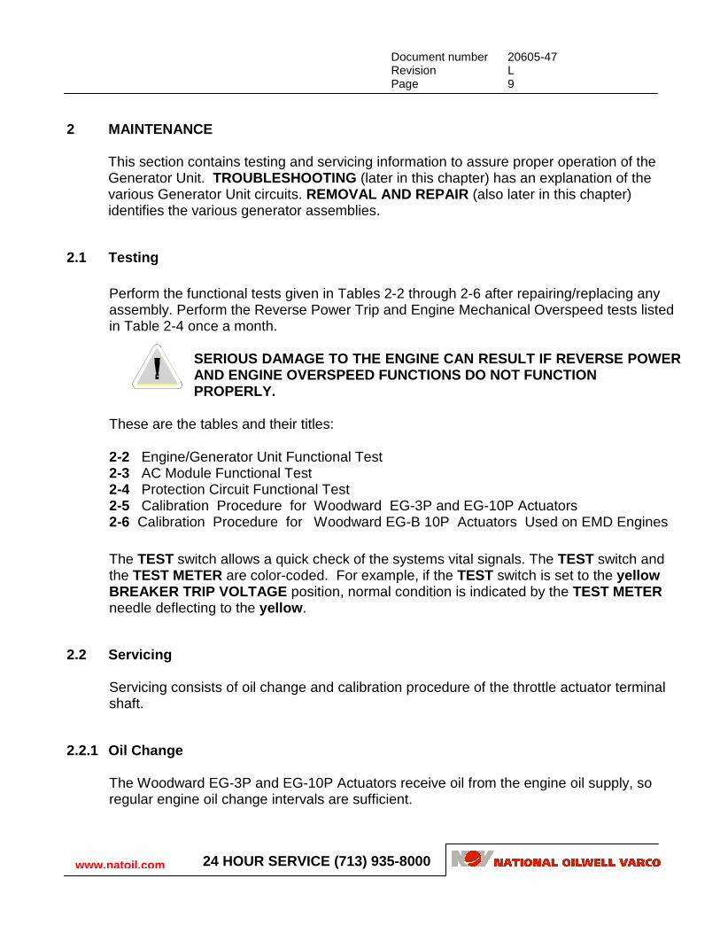
Table 2-4. Protection Circuit Functional Test
ACTION RESULTS
NO PULSE TRIP
A. Connect an engine/generator set to the Main AC Bus.
B. Disconnect TACH SIGNAL lead at AC Control Module Pin 526.
C. Test all remaining engine/generator sets by repeating Steps A and B.
This test applies only to systems equipped with a Tachometer Pulse Pickup circuit.
A. The Generator ON LINE light will illuminate.
B. The Generator Circuit Breaker will trip off line, the engine will die, and the Generator ON LINE light will extinguish.
C. Results will be as shown in Steps A and B.
REVERSE POWER TRIP
A. Connect a generator to the Main AC Bus.
B. Connect a jumper between AC Control Module Pins 533 and 545 (this is the Throttle Output).
Connecting this jumper between pins 533 and 545 will cause a reverse power condition.
C. Once the Generator Circuit Breaker trips off line, remove the jumper between Pins 533 and 545.
A. There are no measurable results from this step.
B. The Generator Circuit Breaker corresponding to the generator will trip off line in eight to 10 Seconds.
C. The engine will return to RUN speed and
the Generator Circuit Breaker will be in the OFF position.

Document number 20605-47 Revision L Page 22
www.natoil.com 24 HOUR SERVICE (713) 935-8000
Table 2-5. Calibration Procedure for Woodward EG-3P and EG-10P Actuators
ACTION RESULTS
SETUP
A. Connect an Ammeter in series with one of the throttle leads which are connected to the Actuator receptacle.
A. There are no measurable results from this step.
B. Set the Ammeter scale to 100 mA. B. There are no measurable results from this step.
C. Open the Generator Circuit Breaker. C. There are no measurable results from this step. D. Start the engine, and bring it up to RUN. D. There are no measurable results from this step.
TERMINAL SHAFT ADJUSTMENT
A. Disconnect the coupling from the actuator shaft (refer to Figure 2-9). Adjust the actuator so that it draws 30 to 60 mA. Monitor the Ammeter of all actuators, in RUN, Off-line, with engine warmed up.
For each 2.5 mA of change desired, rotate the coupling on the threaded rod connected to the actuator shaft ½ to 1 turn.
Actuators and linkages must also be set to conform with the engine manufacturer's specifications. A compromise between the engine manufacturer's specifications and the 30 to 60 mA figure may be necessary.
CATERPILLAR Series 3500 engines do not conform to the 2.5 mA change per ½ to 1 turn of the coupling of the threaded rod.
A. On actuators produced beginning in 1980 Ammeter readings on all units should be within 10 mA of each other. On older units, the Ammeter readings may have to be the same for good load sharing. If you have questions, call the Ross Hill Field Service Office.
Figure 2-9. Actuator Linkage
REASSEMBLY A. Stop the engine.
B. Disconnect the Ammeter and reconnect the throttle lead.
A. There are no measurable results from this step. B. There are no measurable results from this step.
LOCKNUT
THREADEDROD
ACTUATOR
ACTUATOR SHAFT

Document number 20605-47 Revision L Page 23
www.natoil.com 24 HOUR SERVICE (713) 935-8000
Table 2-6. Calibration Procedure for Woodward EG-B 10P Actuators Used on EMD Engines
ACTION RESULTS ACTUATOR CURRENT CHECK
A. Remove the top cover plate by unscrewing the four corner screws. B. Connect an Ammeter, set to read 100 mA, in series with one of the throttle leads which are connected to the terminal strip located in the Engine Control Cabinet, which is adjacent to the engine. C. Open the Generator Circuit Breaker. Start the
engine, and bring it up to RUN. Monitor the actuator current.
D. Compare the actuator currents of all units.
This calibration procedure is to ensure that all of the actuators will work together. In most cases, if the actuator currents of all the actuators are within 10mA between the highest and lowest reading, they will perform properly.
A. A 1/8" Allen Head adjustable Spring Seat will be visible in the middle of the actuator about 1" (2.54 cM) below the top. The seat is held tight by a 5/16" lock nut.
B. There are no measurable results from this step.
C. Record the actuator current, then repeat Steps A, B, and C for all the actuators.
D. Determine which (if any) of the actuators require adjustment. If any do require adjustment, perform the following Terminal Shaft Adjustment procedure on the identified unit(s).
TERMINAL SHAFT ADJUSTMENT A. Loosen the Spring Seat lock nut. Rotate the
Spring Seat 1/4 turn or less in either direction. B. Adjust the Spring Seat until the Ammeter reads
the same as other recorder actuator currents. C. Tighten the Spring Seat lock nut.
PRESSING DOWN ON THE LOCK NUT CAN CAUSE THE ENGINE TO OVER SPEED.
A. Note that the actuator current changes. B. All actuators should draw 30 to 60 mA when the
engines are at RUN RPM, Off-line, and at normal operating temperature.
C. There are no measurable results from this step.
REASSEMBLY
A. Stop the engine. B. Disconnect the ammeter from the actuator circuit
and reconnect the throttle lead. C. Reattach the top cover plate with the four screws.
A. There are no measurable results from this step. B. There are no measurable results from this step.
C. There are no measurable results from this step.

Document number 20605-47 Revision L Page 24
www.natoil.com 24 HOUR SERVICE (713) 935-8000
2.3 Theory of Operation The Generator Unit controls the engine/generator set to deliver a constant AC supply to the Main AC Bus (refer to Figures 2-10 and Figure 2-11). Note that the AC Control Module contains the electronic Engine Governor, Voltage Regulator, Protection and Master/Slave circuits.
2.3.1 Hands-Off Circuit (Hoc) The HOC consists of a battery charging circuit connected to two 12 Volt batteries. Phases A and B of the Main AC Bus are tapped, fused, and then rectified in a diode bridge to obtain the battery charging current. The batteries supply power for the Engine Starting circuit and the Pulse Pickup circuit in the AC Control Module (refer to Figures 2-11 and 2-12).
2.3.2 Generator Circuit Breaker The Generator Circuit Breaker isolates the Main AC Bus from the generator. It has a magnetic trip unit which trips the circuit breaker if current exceeds a preset value. The circuit breaker has a UV (Under Voltage) coil which is interlocked with a AC Control Module Protection circuit. This circuit trips the circuit breaker for various abnormal conditions such as reverse power, under/overfrequency and overvoltage.
2.3.3 Synchronization Panel When the Main AC Bus is energized and another generator supply is to be connected to the Main AC Bus, it is essential to match their voltage and frequencies before closing the Generator Circuit Breaker. This is accomplished by comparing the two frequencies by means of the Synchronization Box (shown in Figure 2-11). When the front panel SYNC switch is in the OFF position, the Sync panel VOLT meter indicates the Main AC Bus voltage. The needle of the SYNCHROSCOPE and the SYNC LIGHTS compare the frequencies of the Main AC Bus and the on-coming generator. The needle of the SYNCHROSCOPE rotates and the SYNC LIGHTS illuminate brightly when the two frequencies are out of phase. When the frequencies and phases are identical, there is no potential across the scope and the lights. As a result, the SYNCHROSCOPE needle remains stationary in the vertical position and both SYNC LIGHTS extinguish.
2.3.4 Engine Governor The electronic Engine Governor controls the engine speed and horsepower, and thereby regulate the generator frequency (refer to Figures 2-13 and 2-14). Located in the AC

Document number 20605-47 Revision L Page 25
www.natoil.com 24 HOUR SERVICE (713) 935-8000
Control Module, the Engine Governor is a feedback control circuit. See the Unique Devices section of this manual for a general description of the feedback control circuit. The governor output is connected to a Throttle Control Actuator (this controls the engine fuel line valve). The Throttle Control Actuator opens the valve in direct proportion to the current applied by the governor through its coil. The coil signal can be monitored at the AC Control Module across Pin 533 (Throttle+) and Pin 545 (Throttle-).

Document number 20605-47 Revision L Page 26
www.natoil.com 24 HOUR SERVICE (713) 935-8000
Figure 2-10. Generator Unit Block Diagram

Document number 20605-47 Revision L Page 27
www.natoil.com 24 HOUR SERVICE (713) 935-8000
Figure 2-11. Generator Unit Circuit

Document number 20605-47 Revision L Page 28
www.natoil.com 24 HOUR SERVICE (713) 935-8000
Figure 2-11. Generator Unit Circuit (Continued)

Document number 20605-47 Revision L Page 29
www.natoil.com 24 HOUR SERVICE (713) 935-8000
Figure 2-11. Generator Unit Circuit (Continued)

Document number 20605-47 Revision L Page 30
www.natoil.com 24 HOUR SERVICE (713) 935-8000
Figure 2-11. Generator Unit Circuit (Concluded)

Document number 20605-47 Revision L Page 31
www.natoil.com 24 HOUR SERVICE (713) 935-8000
Figure 2-12. Hands-Off Circuit (HOC)

Document number 20605-47 Revision L Page 32
www.natoil.com 24 HOUR SERVICE (713) 935-8000
Figure 2-13. Engine Governor Block Diagram
RAMP CKT.
M/S
SWITCH
THROTTLE
ENGINE
PULSE
PICKUP
SPEED REFERENCE
ENGINE CONTROL
SWITCH
MS LOGIC
MASTER/SLAVE
LOGICSLAVE
SLAVE
MASTER
SLAVE
Z8 Z9 Q4
GEN.
GEN. BUS
DEMODULATOR
Ι REAL FEEDBACK
SPEED FEEDBACK
THROTTLE LIMIT
AC MODULE
MASTER SLAVE
TO OTHER
GEN. UNITS
CURRENT CONTROL LOOP
SPEED CONTROL LOOP

Document number 20605-47 Revision L Page 33
www.natoil.com 24 HOUR SERVICE (713) 935-8000
Figure 2-14. AC Module Circuit

Document number 20605-47 Revision L Page 34
www.natoil.com 24 HOUR SERVICE (713) 935-8000
Figure 2-14. AC Module Circuit (Continued)

Document number 20605-47 Revision L Page 35
www.natoil.com 24 HOUR SERVICE (713) 935-8000
Figure 2-14. AC Module Circuit (Continued)

Document number 20605-47 Revision L Page 36
www.natoil.com 24 HOUR SERVICE (713) 935-8000
Figure 2-14. AC Module Circuit (Continued)

Document number 20605-47 Revision L Page 37
www.natoil.com 24 HOUR SERVICE (713) 935-8000
Figure 2-14. AC Module Circuit (Concluded)

Document number 20605-47 Revision L Page 38
www.natoil.com 24 HOUR SERVICE (713) 935-8000
The engine governor employs two feedback control loops. The Outer Speed Control Loop matches the actual generator frequency to the applied speed command. The Inner Current Control Loop matches the horsepower (KW) output of all engines on line.
Speed Control Loop
Op Amp Z8 issues a speed command which is proportional to the difference between the Speed Command and the Composite Speed Feedback. Speed Command is the Speed Reference signal as modified by the Engine Control switch ramp circuit and the Master/Slave Logic signal. Composite Speed Feedback is the sum of the Speed Feedback and Throttle Limit signals.
Speed Reference
This signal is set by the operator on the front panel SPEED ADJUST knob. The SPEED ADJUST knob is linked to a potentiometer which outputs a Zero to +11 VDC signal (pin 551). This corresponds to ≈56 to 64 Hz generator frequency.
Engine Control Switch
When the ENGINE CONTROL switch is moved from IDLE to RUN, the ramp circuit generates an ascending ramp. This steadily increases the gain of Op Amp Z8. The ramp circuit generates a descending ramp when the switch is moved from RUN to IDLE. Changeovers in engine speed are thus accomplished smoothly over a 10 Second time span.
Master/Slave Logic
A signal from the Master/Slave Logic circuit disables the Speed Reference signal when the Generator Unit is in the Slave mode.
Speed Feedback
This signal is a low-level DC analog of the engine speed. At TP 19 in the AC Control Module, the Speed Feedback signal is -2.5 VDC at 60 Hz and ≈+5.0 VDC at 35 to 40 Hz (the IDLE frequency). The Speed Feedback signal is derived either through a Tachometer Pulse Pickup circuit or a Voltage Demodulator circuit. Pulse Pickup Circuit
A magnetic pickup device is mounted near the flywheel of the engine. The magnetic Pickup device emits a pulse each time a flywheel tooth passes by. These pulses are applied to the Pulse Pickup circuit in the AC Control Module as Tach+ (pin 526) and Tach- (pin 527). The pulse signal is processed to derive the Speed Feedback signal. The magnetic pickup device generates it's own voltage and must produce ±2 VRMS. The Pulse

Document number 20605-47 Revision L Page 39
www.natoil.com 24 HOUR SERVICE (713) 935-8000
Pickup also activates the HOC circuit (refer to Figure 2-12). This allows the HOC batteries to power the AC Control Module during the time that the generator voltage is building up. Frequency Demodulator Circuit
Generator phase voltages out of AC Regulator transformer T10 are processed through a Demodulator circuit in the AC Control Module. The Demodulator output is inverted via Op Amp Z5 to obtain a negative Speed Feedback signal. Speed Feedback Switch
The AC Control module is equipped with a circuit that permits the tachometer circuit to provide a speed feedback signal until the generator voltage is >200 VAC. When this occurs, the Speed Feedback Switch operates to connect the Frequency Demodulator Circuit output to the Frequency Regulator as the speed feedback signal. Speed Control Loop
Op Amp Z9 issues a Throttle Current Command which is proportional to the error in signal levels between the Speed Command from Op Amp Z8 and the IREAL (KW) feedback. The output of Op Amp Z9 output is amplified through transistor Q4 and then applied to the Throttle Actuator Coil via Throttle+ (Pin 533) and Throttle- (Pin 545). Master/Slave Logic
The Master/Slave circuit decides which current command Z9 should receive. If the generator is a Master, the Generator Cubicle M/S switch selects the Z8 output. If, however, the generator is a Slave, the Generator Cubicle M/S switch selects the Master/Slave signal (pin 543). This signal is the Master generator Z8 output.
The Master/Slave Logic circuit detects whether the generator is the Master or Slave. The Master/Slave Logic circuit receives the M/S Logic signal from the Generator Circuit Breaker (pin 544) and Slave signals which are the M/S Logic signals of the other generators (pins 537 through 542). Table 2-7 is the Master/Slave Truth Table.
Figure 2-15 shows the Master/Slave circuit. The Master/Slave Logic switches from ≈10 VDC (this voltage is approximate since it is partially dropped through a resistor) to -16 VDC when the circuit breaker is closed to connect the generator to the Main AC Bus. The Master/Slave Logic of each generator is connected to the Slave inputs of the following higher-numbered generators. As a result, the Master generator is always the one with the lowest number. Generator 1 is never a Slave unit since it doesn't receive any Slave inputs. If Generator 1 is off, the lowest-numbered generator connected to the Main AC Bus becomes the master.
Note that Master/Slave lines of all generators are tied together.

Document number 20605-47 Revision L Page 40
www.natoil.com 24 HOUR SERVICE (713) 935-8000
Table 2-7. Master/Slave Truth Table
M/S Logic Slave Result
≈10 VDC ≈10 VDC The generator is disconnected from the Main AC Bus.
-16 VDC ≈10 VDC The generator is the Master.
-16 VDC -16 VDC The generator is the Slave.
IREAL Feedback
IREAL is a low-level DC analog of the real current produced by the generator (IREAL x E = KW). Generator phase voltages out of transformer T10 and line currents out of CT1, CT2, and CT3 are processed in the AC Control Module through a current demodulator to develop ITOTAL, I REAL and IREACTIVE signals (refer to Figure 2-10).
2.3.5 Voltage Regulator This controls the generator's exciter current through the exciter power supply to regulate the generator voltage (refer to Figures 2-11, 2-13, 2-16, and 2-17). The Voltage Regulator output can be monitored across Generator EX+ (TB11-7) and Generator EX- (TB11-8). It should be +10 VDC during IDLE and ≤+70 VDC during RUN for a nominal 100 VDC exciter.
The Voltage Regulator employs two Feedback Control Loops (Inner and Outer). The Outer provides overall regulation by matching the generator voltage to the Voltage Reference. The Inner regulates the Exciter Field Supply. Op Amp Z1 issues the Exciter Current Command. It is proportional to the error difference between the Voltage Reference and Voltage Feedback signals.

Document number 20605-47 Revision L Page 41
www.natoil.com 24 HOUR SERVICE (713) 935-8000
Figure 2-15. Master/Slave Wiring Diagram
Exciter Current Command. It is proportional to the error difference between the Voltage Reference and Voltage Feedback signals. Voltage Reference This is set by the operator on the front panel VOLTS ADJUST knob. The knob is linked to a potentiometer which outputs a Zero to +11 VDC signal (Pin 551). This +11 VDC corresponds to maximum voltage. Voltage Feedback Voltage Feedback is a low-level DC analog of the generator voltage. The generator AC line voltages are applied to the primary of Control Transformer (600:115 VAC) T10. T10 has a Delta/Star configuration. The six AC phase voltages from the secondary are rectified and reduced in value to give the feedback signal. IREACTIVE is a low-level DC analog of the generator reactive current (IREACTIVE x E = KVARs).
MS LOGIC
MASTER SLAVE
SLAVE
SLAVE
SLAVE
PIN NO. PIN NO. PIN NO.
AC MODULEGEN. 1
AC MODULEGEN. 2
AC MODULEGEN. 3
CB AUX. CB AUX. CB AUX.
-16 VDC -16 VDC -16 VDC
544 544 544
543 543 543
542 542 542
541 541 541
540 540 540

Document number 20605-47 Revision L Page 42
www.natoil.com 24 HOUR SERVICE (713) 935-8000
Figure 2-16. Voltage Regulator Block Diagram
Figure 2-17. Exciter Field Supply Circuit
SCR
FIRING
CIRCUITZ1 Z2
AC
MTR
EXCITER
GEN.
BUS
GENERATOREXCITER
FIELD
SUPPLY
VOLT.
REFER.
UNDER FREQUENCY
CUTBACK
Ι
AC MODULE
VOLTAGE FEEDBACK
EXCITER CURRENT FEEDBACK
EXCITER CURRENT CONTROL LOOP
VOLTAGE CONTROL LOOP
REACTIVE

Document number 20605-47 Revision L Page 43
www.natoil.com 24 HOUR SERVICE (713) 935-8000
The voltage feedback and current feedback signals are processed in the AC Control Module to derive the IREACTIVE signal.
The IREACTIVE signal is negligible during startup when the circuit breaker is open since minimal current flows out of the generator. Voltage Reference is the only effective signal. The VOLTS ADJUST knob can be adjusted to set the generator voltage to the operating level. When several generators are connected to the Main AC Bus, the terminal voltage is held fixed by other generators. The VOLTS ADJUST knob can now be adjusted to bias the IREACTIVE signal so as to distribute the reactive current (KVARs) equally among all generators.
The Underfrequency Cutback Signal is developed from the frequency feedback. It applies a negative bias to the summing junction of voltage regulator Op Amp Z1 to cutback the generator voltage when frequency drops below 50 Hz. At IDLE, when the frequency is 35 to 45 Hz, the voltage is between ≈300 VAC to 450 VAC.
2.3.6 Exciter Current Control Loop Op Amp Z2 controls the SCR firing circuit firing angle so that the exciter field current matches the Op Amp Z1 current command.
The generator output (refer to Figure 2-17) is stepped down and rectified to produce the exciter current. Two rectifier circuits are used: a diode bridge made up of DB1 and DB2 during startup. Thereafter, a half- controlled bridge made up of two diodes (DB2) and two SCRs (SCR1, SCR2). During startup, generator residual voltage is rectified through the diode bridge and applied to the Exciter. The Metal Oxide Varistor (MOV) clamps bridge voltage to +250 VDC. Through positive feedback, the Exciter voltage, and in turn, the generator voltage quickly builds up. When the voltage is sufficient to energize the AC Control Module, build-up relay K1 energizes to switch the transformer output to the half-controlled bridge. The Exciter current feedback to the Op Amp Z2 summing junction (IEX + and IEX -) is +0.33 VDC per 1.0 Amp of Exciter current (or as adjusted by the connection of current-sensing resistors).
2.3.7 Protection Circuit This circuit (refer to Figures 2-13 and 2-18) compares the generator supply parameters against their respective preset limits.
It consists of a Protection switch controlled by the reverse power, under/overfrequency and the overvoltage detector.

Document number 20605-47 Revision L Page 44
www.natoil.com 24 HOUR SERVICE (713) 935-8000
The Protection switch, made up of transistor Q3 and relay K2, deenergizes the Under Voltage (UV) coil to trip the Generator Circuit Breaker. In some systems, the Generator Circuit Breaker has a Shunt Trip coil and a UV coil. In these systems, the Shunt Trip coil is wired to a switch on the Generator Cubicle. Closing this switch will energize the Shunt Trip coil, thus causing the Generator circuit breaker to trip.
Figure 2-18. Protection Circuit Block Diagram
2.3.8 Reverse Power Detector When an engine is running normally, it supplies power to the Main AC Bus. This power is measured in terms of KWs. The front panel KW METER will display a normal positive value (> zero). However, when fuel to the engine is cut off due to overtemperature, oil pressure or because of a clogged fuel filter, the corresponding KW meter will display a negative reading (below zero). This is because power flows from the bus into the generator of the faulty engine. The generator functions as a synchronous motor which keeps the faulty engine running.
GEN. BUS
AC MODULE
AC BUSAC
CIRCUITBREAKER
CB
TRIP
NO PULSE
I REAL
FREQUENCY
FEEDBACK
VOLTAGE
FEEDBACK
REVERSEPOWER LIGHT
UNDER FREQ.CUTBACK
REVERSEPOWER
DETECTORZ6, Q1, K1
UNDER/OVERFREQUENCYDETECTORZ7, Z14
OVER VOLTAGEDETECTOR
Q6
PROTECTIONSWITCHQ3, K2 UV

Document number 20605-47 Revision L Page 45
www.natoil.com 24 HOUR SERVICE (713) 935-8000
This is termed the reverse power phenomenon. Normally-running engines will force a faulty-running engine to run at the same speed because of the magnetic coupling linking the generators by way of the Main AC Bus.
Comparator Z7 in the Protection circuit monitors the IREAL (Kilowatts) feedback signal to trigger the Protection switch when the signal exceeds the preset limit. The time delay before tripping of the circuit breaker is a function of the level of the reverse KW. For example, if reverse power is 7%, the Circuit Breaker will trip in eight to 12 Seconds.
2.3.9 Underfrequency Detector Comparator Z6 triggers the Protection switch if the frequency feedback signal indicates that the frequency is below 50 Hz. Z6 also applies the Underfrequency Cutback signal to the Voltage Regulator circuit to reduce generator voltage.
2.3.10 Overfrequency Detector Comparator Z14 triggers the Protection switch if frequency feedback signal says that the frequency is 67 to 68 Hz.
2.3.11 Overvoltage Detector The Voltage Feedback signal is applied to a voltage divider circuit made of resistors R90 and R96. The output of the voltage divider will trigger Q6 if the line voltage >≈1.16 x normal bus voltage.
2.3.12 No Pulse Detector The No Pulse signal will switch from +16 VDC to -16 VDC when the Pulse Pickup circuit does not receive pulses from the Magnetic Pickup device (this is located near the engine flywheel).
The Protection switch operates 100 mS after loss of magnetic pulses from the engine. This will prevent nuisance tripping of the circuit breaker.
2.3.13 Power Limit Circuit The Power Limit Circuit prevents the load from exceeding the capacity of engines on line. The circuit monitors IREAL (KWs) and ITOTAL (KVAs) of all the generators to keep the SCR bridges on line from demanding more of either KWs or KVAs that would exceed preset limits. This action distributes the available power equally among the SCR bridges. The
Document number 20605-47 Revision L Page 46
www.natoil.com 24 HOUR SERVICE (713) 935-8000
power limit is normally set at ≈95% of the engine's horsepower rating and 100% of the generator's KVA rating.
Note that IREAL and ITOTAL signals are generated in the AC Control Module and auctioneered together so that only the signal from the most highly loaded engine/ generator goes to the power limit circuit (see Figures 2-11, 2-14, 2-19 and 2-20).

Document number 20605-47 Revision L Page 47
www.natoil.com 24 HOUR SERVICE (713) 935-8000
Figure 2-19. Power Limit PC Card Schematic Diagram

Document number 20605-47 Revision L Page 48
www.natoil.com 24 HOUR SERVICE (713) 935-8000
Figure 2-20. Power Limit PC Card Layout
The IREAL and ITOTAL signals are low-level DC analog signals representing the real and total currents developed by the generator. Generator line currents are stepped down through current transformers CT1, CT2 and CT3. The resulting low level AC signals are rectified and processed in a current demodulator in the AC Control Module with the generator phase voltages and rectified to derive IREAL and ITOTAL. The IREAL and ITOTAL signals of all generators connected to the Main AC Bus are auctioneered to select the signals with the highest positive values. The Power Limit signal (Op Amp Z1-6) goes positive as the load increases. It is +0.25 to +0.5 VDC measured at Pin 12 of the Power Limit Board at power limit. When the load exceeds the power limit, the Power Limit signal positively biases the negative Firing Reference signals to all SCR bridges on line. Op Amp Z2 ramps input
Document number 20605-47 Revision L Page 49
www.natoil.com 24 HOUR SERVICE (713) 935-8000
signal to Z1 from 75% of Power Limit to allow the prime mover to handle a large change demand for power. Transistor Q1 turns on at power limit to turn on the Driller's Console POWER LIMIT light. In some systems, Op Amp Z4 output is used to drive the Driller's Console POWER LIMIT meter.
2.3.14 AC Ground Fault Detection Circuit This circuit (refer to Figure 2-11) consists of three lights. One side of each light connects to a phase of the Main AC Bus. The light's other side is grounded. If an AC phase becomes grounded, the light corresponding to that phase is extinguished. The other two lights become more brightly illuminated. A small C.T. drives a meter to indicate the percent of the AC ground. This manual's SCR Unit section describes the DC Ground Fault Detection circuit.
2.4 Troubleshooting Table 2-8 gives troubleshooting information for engine malfunctions. Table 2-9 gives troubleshooting information for Generator malfunctions. Table 2-10 gives troubleshooting information for the AC Control Module.

Document number 20605-47 Revision L Page 50
www.natoil.com 24 HOUR SERVICE (713) 935-8000
Table 2-8. Engine Malfunctions
SYMPTOM/PROBABLE CAUSE ACTION
ENGINE WILL NOT RUN
A. Engine overspeed lever not reset. A. Reset the lever.
B. No power to the actuator. Throttle drops shut if the fuel rack is not held open by hand. The possible causes are:
B. The actions for the possible causes are:
1. Leads to the throttle actuator are either open, short-circuited, or grounded.
1. Measure resistance between Generator TB11-1 and Generator TB11-2 (Throttle + and -) with both leads lifted. It should read 30Ω.
2. The AC Control Module in the Generator Cubicle is not providing control current to the throttle.
2. Measure current going to the Throttle Actuator at throttle + or Throttle -. It should be 30 to 60 mA when engine is at run speed. If there is no or low current, replace the AC Control Module.
3. No signal from the engine pulse pickup (if used).
3. Set the Voltmeter on its lowest AC Volts range. The pulse pickup must deliver at least 2 VAC at engine crank speeds.
ENGINE RUNNING PROBLEMS
A. Engine speed oscillates up and down at a steady rate. Observe the engine throttle arm.
A. Speed may oscillate for a short time during cold starts (this is normal). If it continues to oscillate, the AC Control Module may be malfunctioning. If so, call Ross Hill.
B. Engine speed varies erratically without any steady oscillation. The possible causes are:
B. The actions for the possible causes are:
1. Intermittent connection on the throttle circuit. 1. Check for/repair any intermittent connections.
2. Defective AC Control Module. 2. Replace with spare AC Control Module.
C. Engine speed cannot be raised to 50 Hz. C. The AC control voltages from transformers not reaching the AC Control Module. Troubleshoot and repair. With the EG-B-10P throttle actuator, be sure SPEED knob setting is set to MAXIMUM.
D. Engine speed cannot be adjusted. D. Faulty SPEED ADJUST rheostat. Troubleshoot and repair.

Document number 20605-47 Revision L Page 51
www.natoil.com 24 HOUR SERVICE (713) 935-8000
Table 2-8. Engine Malfunctions (Concluded)
SYMPTOM/PROBABLE CAUSE ACTION
E. Engine speed and KW sharing problems. E. AC Control Module is defective. Check the actuator current.
F. Generator Circuit Breaker does not automatically trip for reverse power, under/overfrequency, or no pulse faults. There are two possible causes:
F. The actions for the possible causes are:
1. Defective AC Control Module. 1. Replace with spare.
2. Circuit Breaker UV is faulty. 2. Troubleshoot and repair/replace as required.
Table 2-9. Generator Malfunctions
SYMPTOM/PROBABLE CAUSE ACTION
AC VOLTS ABSENT OR <150 VAC. A. Engine speed is too low. A. If the Main AC Bus voltage will not increase, raise
the speed to RUN setting when starting.
Measure the voltage across Exciter Field+ (GEN TB11-7) and Exciter Field- (GEN TB11-8). It must be at least 1 VAC during starting. Check the Generator Residual Voltage. At full speed, it should be ≈15 to 20 VAC.
If both of the above conditions do not exist, the Generator Residual Voltage is insufficient. In this case, supply an external current to the Generator Exciter Field (this procedure is called flashing the Exciter Field ).
B. Exciter fuses are blown, or the Exciter Field Supply Circuit is defective.
B. Troubleshoot the Exciter Field Supply Circuit.
C. Shorted diode in the generator rotating rectifier. C. Troubleshoot and repair the generator.
D. Generator Residual Voltage insufficient. D. Flash the Exciter Field.
AC VOLTAGE REACHES 150 TO 200 VAC BUT DOES NOT INCREASE TO 600 VAC
A. Defective Exciter Printed Circuit Card. A. Replace the Exciter Printed Circuit Card.
B. Defective AC Control Module. B. Replace with spare AC Control Module.
Document number 20605-47 Revision L Page 52
www.natoil.com 24 HOUR SERVICE (713) 935-8000
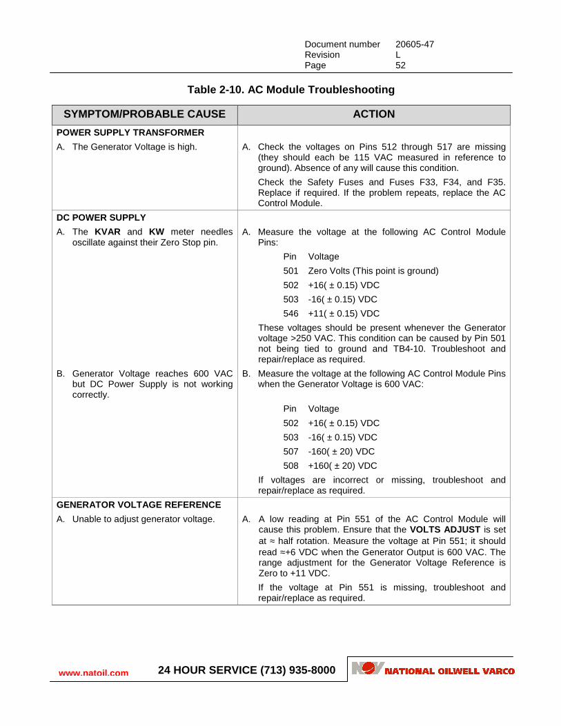
Table 2-10. AC Module Troubleshooting
SYMPTOM/PROBABLE CAUSE ACTION
POWER SUPPLY TRANSFORMER
A. The Generator Voltage is high. A. Check the voltages on Pins 512 through 517 are missing (they should each be 115 VAC measured in reference to ground). Absence of any will cause this condition.
Check the Safety Fuses and Fuses F33, F34, and F35. Replace if required. If the problem repeats, replace the AC Control Module.
DC POWER SUPPLY
A. The KVAR and KW meter needles oscillate against their Zero Stop pin.
A. Measure the voltage at the following AC Control Module Pins:
Pin Voltage
501 Zero Volts (This point is ground)
502 +16( ± 0.15) VDC
503 -16( ± 0.15) VDC
546 +11( ± 0.15) VDC
These voltages should be present whenever the Generator voltage >250 VAC. This condition can be caused by Pin 501 not being tied to ground and TB4-10. Troubleshoot and repair/replace as required.
B. Generator Voltage reaches 600 VAC but DC Power Supply is not working correctly.
B. Measure the voltage at the following AC Control Module Pins when the Generator Voltage is 600 VAC:
Pin Voltage
502 +16( ± 0.15) VDC
503 -16( ± 0.15) VDC
507 -160( ± 20) VDC
508 +160( ± 20) VDC
If voltages are incorrect or missing, troubleshoot and repair/replace as required.
GENERATOR VOLTAGE REFERENCE
A. Unable to adjust generator voltage. A. A low reading at Pin 551 of the AC Control Module will cause this problem. Ensure that the VOLTS ADJUST is set at ≈ half rotation. Measure the voltage at Pin 551; it should read ≈+6 VDC when the Generator Output is 600 VAC. The range adjustment for the Generator Voltage Reference is Zero to +11 VDC.
If the voltage at Pin 551 is missing, troubleshoot and repair/replace as required.

Document number 20605-47 Revision L Page 53
www.natoil.com 24 HOUR SERVICE (713) 935-8000
Table 2-10. AC Module Troubleshooting (Concluded)
SYMPTOM/PROBABLE CAUSE ACTION
ENGINE SPEED REFERENCE
A. Engine speed is low and/or AC Circuit Breaker trips due to underfrequency.
A. Absence of a signal at Pin 547 of the AC Control Module will cause this problem. Set the SPEED REFERENCE to 60 Hz and then measure the voltage at Pin 547. It should be +6 VDC. The range adjustment for the Engine Speed Reference is Zero to +11 VDC.
If the voltage at Pin 547 is missing, troubleshoot and repair/replace as required.
CIRCUIT BREAKER TRIP
A. Circuit Breaker has tripped. A. Measure the voltage between Pins 528 and 529 (the UV Trip). The voltage should be Zero Volts. If the voltage is +24 VDC, The Trip Relay in the AC Control Module has not picked up and the Circuit Breaker has tripped.
THROTTLE OUTPUT
A. Engine will only run when throttle is held by hand.
A. Measure the current from either Pin 533 or 545 when the engine is at RUN speed with NO LOAD , the reading should be 30 to 60 mA. If the engine is at RUN speed with FULL LOAD , the reading should be 180 to 200 mA.
Check for an open circuit between the throttle leads and repair/replace as required. If the actuator resistance is 30 to 36Ω try replacing the AC Control Module.
EXCITER SCR GATE PULSES
A. The Generator Voltage oscillates between 10 VAC and 300 VAC as the Field Supply Build-Up Relay opens and closes.
A. Using an Oscilloscope, check for the presence of firing pulses at AC Control Module Pins 504 and 505.
If the firing pulses are missing, replace the AC Control Module.
EXCITER CURRENT FEEDBACK
A. Generator voltages out of regulation. A. Use an Oscilloscope to monitor the voltage between Pin 556 of the AC Control Module and ground. Compare this waveform with the waveform of a known good generator.
AC CURRENT FEEDBACK
A. There is a load imbalance between the generators connected to the Main AC Bus.
A. Measure the voltage between the following AC Control Module Pins with an Oscilloscope: 519 to 520, 521 to 522, and 523 to 524. The voltage measured should be Zero Volts at NO LOAD , and +2.5 VDC at FULL LOAD . If the voltage between any of these AC Control Module Pins is missing, troubleshoot and repair/replace as required.

Document number 20605-47 Revision L Page 54
www.natoil.com 24 HOUR SERVICE (713) 935-8000
Table 2-10. AC Module Troubleshooting (Concluded)
SYMPTOM/PROBABLE CAUSE ACTION
MASTER/SLAVE
A. A large KW load imbalance between the engines. This is probably caused by improper actuator current adjustment.
There are several other, though less common, reasons for a large KW load imbalance: a defective KW Meter, a defective AC Control Module, a bad Actuator, or an engine problem.
A. Start an engine/generator and allow it to operate until it is at normal running temperature. Adjust the generator frequency to 60 Hz. Disconnect the generator circuit breaker and then measure the actuator current at either Pin 533 or 545 of the AC Control by connecting a multimeter (set on the 100 mA scale) in series with the wire going to the pin. Actuator current must be 30 to 60 mA. If it is not within that range, adjust until it is. Perform this with all of the engine/generators. Ensure that all of them have an actuator current that falls within a 10 mA range between the smallest and largest. All actuator's currents must fall with the 30 to 60mA range given above.

Document number 20605-47 Revision L Page 55
www.natoil.com 24 HOUR SERVICE (713) 935-8000
3 HI-LINE OPERATION Hi-Line operation allows you to replace or supplement the electrical power obtained from your engine/generators with electrical power obtained from a commercial power company. If this source of power is available at your site, the cost savings of utilizing Hi-Line operation can be considerable.
The Hi-Line operation is primarily performed by a step-down transformer and two circuit breakers (refer to Figure 2-21). There are other circuit components that allow control or monitoring of Hi-Line operation. These other components are shown in Figure 2-22.
Figure 2-21. Typical Basic Hi-Line
The values for the step-down transformer and circuit breakers shown in Figure 2-21 are given for illustration purposes. The values selected for your particular system may differ.
In Figure 2-21, either or both of the circuit breakers will supply voltage from the step-down transformer to the system's AC Bus. If only one circuit breaker is closed, the power delivered to the system's AC Bus will be limited to the rating of the connected circuit breaker (typically ≈50% of the step-down transformer's rating). Figure 2-22 shows the lineup of a typical SCR system containing a Hi-Line Incomer Cubicle.
The two circuit breakers in Figure 2-21 labeled MC B1 and MCB2 are the same as the Items 31(Hi-Line Incomer Circuit Breaker) i n Figure 2-22.
In the following item descriptions, all references are to items shown in Figure 2-22.
BUS
600 VAC
13,800 V (or Higher)3000 KVA
MCB11600AF
MCB21600AF/AT
LOCATED INHI-LINE CUBICLE

Document number 20605-47 Revision L Page 56
www.natoil.com 24 HOUR SERVICE (713) 935-8000
Three items are Hi-Line controls:
• Two HI-LINE INCOMER CIRCUIT BREAKER s (Items 31).
• REVERSE POWER TRIP RESET Lighted Push Button (LPB) switch (Item 40).
The REVERSE POWER TRIP LPB is disabled if the Engi ne/Generator cannot be paralleled with the HiLine Transformer.
The remainder of the items on the Hi-Line Incomer Cubicle are indicator lights or meters.
The AC AMMETER (Item 32) displays the total current being supplied by the Hi-Line's step-down transformer. The KILOWATT METER (Item 33) displays the total real power being supplied by the Hi-Line Incomer Cubicle. The KVAR METER (Item 34) displays the total reactive power being supplied by the Hi-Line Incomer Cubicle. The AC VOLTMETER displays the AC voltage being supplied by the Hi-Line Incomer Cubicle to the Main AC Bus.
The UTILITY OK (Item 35) lamp illuminates if there is no problem with the incoming commercial power. The REVERSE PHASE ROTATION lamp (Item 36) illuminates if the incoming commercial power has been connected out of phase with the Main AC Bus. The PHASE LOSS lamp (Item 37) illuminates if there is a phase loss of the incoming commercial power. The MCB1 CLOSED lamp (Item 41) illuminates if Main Circuit Breaker 1 is closed. The MCB2 CLOSED lamp (Item 42) illuminates if Main Circuit Breaker 2 is closed.

Document number 20605-47 Revision L Page 57
www.natoil.com 24 HOUR SERVICE (713) 935-8000
Figure 2-22. Typical SCR System Containing a Hi-Lin e Incomer Cubicle

Document number 20605-47 Revision L Page 58
www.natoil.com 24 HOUR SERVICE (713) 935-8000
4 REMOVAL & REPAIR
4.1 Model 1000 In the Model 1000, the Generator Unit assemblies (refer to Figure 2-23) are mounted inside the Generator Cubicle on the door and side panels.
Figure 2-23. Model 1000 SCR/Generator Cubicle

Document number 20605-47 Revision L Page 59
www.natoil.com 24 HOUR SERVICE (713) 935-8000
4.2 Model 1400 In the Model 1400, the Generator Unit assemblies (refer to Figure 2-24) are mounted inside the Generator Cubicle on the door and side panels.
Figure 2-24. Model 1400 Generator Cubicle

Document number 20605-47 Revision L Page 60
www.natoil.com 24 HOUR SERVICE (713) 935-8000
4.3 Model 1861 In the Model 1861, the Generator Unit assemblies (refer to Figure 2-25) are mounted inside the Generator Cubicle on the door and side panels.
Figure 2-25. Model 1861 Generator Cubicle