Embed Size (px)
Citation preview

Generation of Porous StructuresUsing.Fused.D~position
Bertoldi M., Yardimci M. A., Pistor C. M., GUyeri S. 1., Danforth S. C.
University of Illinois at Chicago & Rutgers University
ABSTRACT
The Fused Deposition Modeling process uses hardware and software machine-level
language that are very similar to that of a pen-plotter. Consequently, the· use of patterns withpoly-lines as basic geometric features, instead of the current method based on filled polygons(monolithic models), can increase its efficiency.
In the current study, various toolpath planning methods have been developed to fabricateporous structures. Computational domain decomposition methods can be applied to the physicalor to slice-level domains to generate structured and unstructured grids. Also, textures can becreated using periodic tiling of the layer with unit cells (squares, honeycombs, etc). Methods'based on curves include fractal space filling curves and.change of effective road width Within a
layer or within a continuous curve. Individual phases can also be placed in binary compositions.
In present investigation, a custom software has been developed and implemented togenerate build files (SML) and slice files (SSL) for the above-mentioned structures, demonstrating the efficient control of the size, shape, and distribution ofporosity.
INTRODUCTION
Two dimensional pattern generation capability of RP/SFF .methods is not being fullyutilized currently due to use of very .limited set of toolpath generation algorithms and datarepresentation problems associated with heterogeneous structures. Generation .ofcontrolledporosity structures with RP/SFF has been particularly challenging due to the need of defining theentire porous structure as a very complicated solid object.
Porosity generation within solid models with RPISFF .• processes has been investigated in
the context of investment casting with ·•SLA •fabricatediconstantpcrtesize patterns. ••• Two"dimensional equilateral· triangular and square self-repeating patterns were developed by
Systems, three-dimensional laminated hexagonal structures>by the University of Nottingham
group [1] and three-dimensional tetragonal crystalline structures by Gervasi and coworkers [2].
639

Recently, rectangular porous interior structures were adopted by Stratasys in Fused Deposition
and tetragonal patterns by Z-Corporation in 3D printing for build acceleration. The
comp~tational geoIIletry •. definition problem of heterogeneous.structures has been investigated[3]; however, this study does not address the generation of porous structures inside solid models.
:Fused Deposition can be consid~red as a vector printing technique, in which the twodimensional patterns are generated with poly-lines on a discretized x-y plane. Boundarydeposition and subsequent raster filling is employed during production; voids appear in the rasterfilling, due to the finite road width; .this can be used to produce specific porosity. However,current Fused Deposition process plannin.g software only allows for constant layer thickness
across the entire part, constant road width within each layer, contour or rectilinear rasters,monolithic material composition, and constant air-gap between raster patterns. As a result, thevariety of attainable porous structures is very limited.
A set of software tools has been. developed and used to generate porous structures,showing the feasibility of the concepts presented. Since layer geometries are inherently twodimensional, the remainder of the presentation will be focused on two-dimensional gridgeneration.
TWO DIMENSIONAL TEXTURES
Basic texture structures employed by computer graphics methods, such as square blocksand honeycombs, can fill a plane by tiling the basic unit periodically. The variety of microstructures can be increased by recursively constructing higher-order unit cells that fill the plane
through periodic tiling, as·shown in Figure 1.
o
Figure 1 Unit cell and resulting texture.
Texture based patterns can be generated once the underlying unit cell is designed
properly to fill the entire plane. The texture needs to be clipped to fit into the layer geometrydescribed by the contours, which increases the computational requirements. The unit cell nature
of the textures enforces a homogeneous pore size and microstructure distributions throughout the
entire part, which limits the use of this technique.
640

STRUCTURED GRID GENERATION
Structured grids are used in the simulation of complex physical processes, where
discretization of the domain of interest into geometrically simple sub-structures is required.Systems of algebraic or ordinary differential equations representing the physical phenomena are
defined over the discretized domain, with appropriate variable transformations [4]. UniformCartesian grids within rectangles and circular geometries can be generated, employing linear
functions and coordinate transformations, as depicted in Figure 2.
-500
o
~~IOOO500.1000
o 500
Figure 2 Uniform Cartesian grids.
The resultant grids have regular porosity distributions, which can be manipulated only byvarying grid spacing independently along the coordinate axes. The porosity can be bettercontrolled through use of nonlinear stretching functions as mapping functions from computational to physical space. One example of stretching functions to generate boundary clustering is:
( ~[( ) ( )]k-a)/(,-a)2a + jJ) jJ+1 / jJ - 1 + 2 a - jJ
(xmax - xmin) ( ) {[( ) ( )](q-a)/(l-al} + xmin
2a+1 1+ jJ+1 / jJ-1
( ~[( ) ( )](11-a)/(I-a)2a+~jJ+l/jJ-l +2a-jJ
(ymax - Ymin) ( ) { [( ) ( )](11-a)/(I-al} + Ymin2a+1 1+ jJ+l / jJ-1
(1)
where ~ and 11 denote coordinates in computational space. The generated grids are presented inFigure 3.
Although Cartesian grids are powerful geometric. discretization tools for simple domains,
they are not directly adaptable for arbitrary two-dimensional domains and have to be used as
background textures with polygon dipping methods. Complex geometry physical simulation
641

necessitated the development of boundary conforming, or boundary fitted curvilinear grid
methods [5].,..---------, 3000
2000
1000
o y-1000
-2000
x
Figure 3 Non-uniform Cartesian grids with boundary clustering.
Boundary conforming structured grids can be efficiently produced by using algebraicinterpolation methods. Portions of domain boundaries in physical space are associated withdomain edges in computational space. Interpolation methods are utilized to generate coordinatesof interior grid nodes; a two-boundary interpolation of a circle is presented in Figure 4.
3000
2500
2000
1500 Y
1000
500
Figure 4. Boundary conforming grid generated with two-boundary interpolation.
Greater flexibility of boundary conformity can be obtained through higher order interpolation
algorithms, e.g. transfinite interpolation:
r . = pi + pj _ pij',J
pi =h f;m,j +(1- h)~,j , pj =gj f;,jm +(1- gj )f;,l
pij = h gj f;m,jm +h (1- gj )f;m,l +(1- h)gJ"jm +(1- h )(1- gj )~,li-I }-1
Ii =-.-1 ' gj =-'-1zm- ;m-
(2)
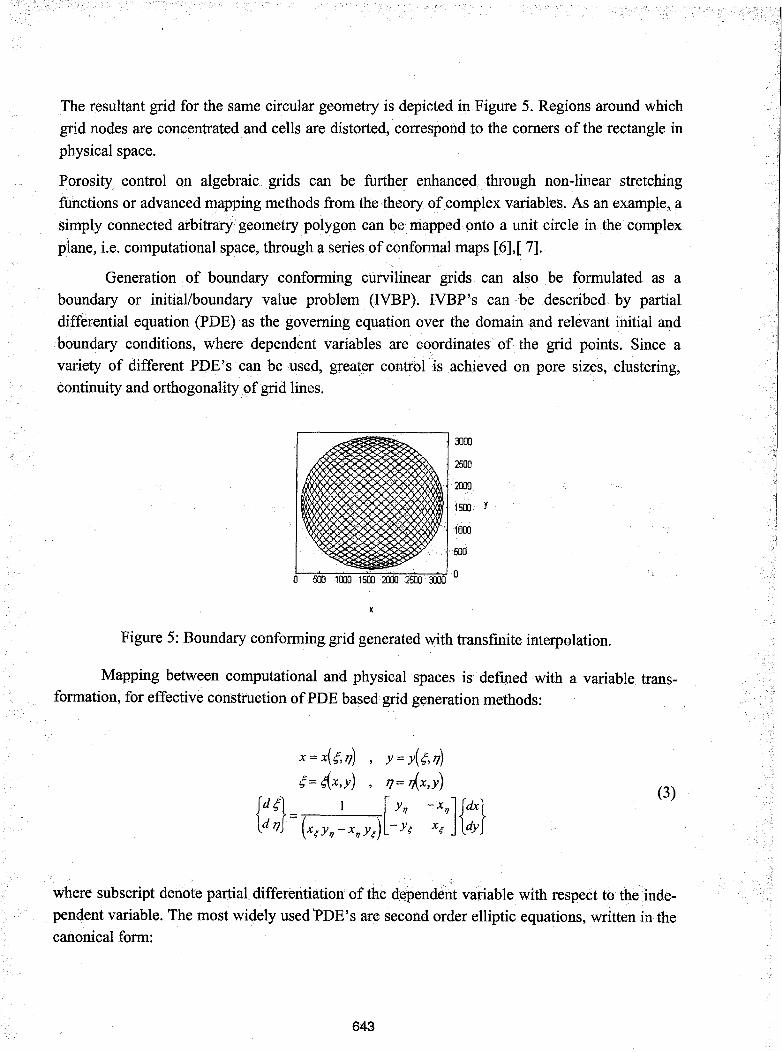
The resultant grid for the same circular geometry is depicted in.Figure 5. Regions around whichgrid nodes are concentrated and cells are distorted, correspond to the comers of the rectangle in
physical space.
Porosity control on algebraic .. grids can be further enhanced through non-linear stretchingfunctions or advanced mapping methods from the theory of complex variables. As an example,.asimply connected .arbitrary geometry polygon can be mapped onto a unit circle in the complex
plane, i.e. computational space, through a series of conformal maps [6],[ 7].
Generation of boundary conforming curvilinear grids can also be formulated as aboundary or initial/boundary value problem (IVBP). IVBP's can be described by partialdifferential equation (PDE)as the governing equation over the domain and relevant initial and
boundary conditions, where dependent variables are coordinates of the grid points. Since avariety of different PDE's· can be used, greater control is achieved on pore sizes, clustering,continuity and orthogonalitypf grid lines.
3000
2500
2000
1500 Y
1000
500
Figure 5: Boundary conforming grid generated with transfinite interpolation.
Mapping between computational and physical spaces is defined with a variable transformation, for effective construction ofPDE based grid .generation methods:
x =X(4'",17) , Y=Y(4'",'l)4'"= 4{'x,y) , 17= r,{x,y)
{:~} =(x,y, ~x,y,l:;, -x:'H:}(3)
where subscript denote partial differentiation of the dependent variable with·respect totheindependent variable. The most widely used 'PDE's are second order elliptic equations, written in thecanonical form:
643

(4)
For grid generation, a system of elliptic PDE's can be constructed with grid coordinatesas dependent variables in respective problem spaces:
c1- ~+ c1- ~ = p c1- '7 c1- '7 Q (;:) (ti-) J-)) _2 2 , -2+-2 = , .",'7 = S\r ,,/\r r Erpox oY ox oY
or
(5)
where (P,Q) are grid control parameters in physical space with their counterparts (<I>,<p) incomputational space. Since Dirichlet (constant value) type boundary conditions are specified for
the BVP,the elliptic PDE'sonly needto be solved in the interior of the domain. The discretiza
tionofequations with central differences and employment of successive over-relaxation (SOR)
iterative method, results in the following algebraic system:
i = l...im, j = l...jm
x;.j = 2(A:C)[A (Xi_l,j +Xi+l,j +~(Xi+l,j -Xi_l,j)) + ~ (Xi_l,j_1 -Xi+l,j_1 -XH,j+1 +Xi+l,j+l)
+ c(Xi,j_1 + Xi,j+! + i (Xi,j+1 Xi,j_I)) +(1- m)xi,j (6)
Y;,j = 2(A: C)[ A(Yi-I,j +Yi+l,j +~(Yi+l,j - YH,j)) + ~ (Yi-I,j-I - Yi+l,j-1 - Yi-l,j+1 +Yi+l,j+l)
+ C(Yi,j_1 +Yi,j+! + i (Yi,j+1 - Yi,j-I)) +(1- m)Yi,j
A_ (Xi,j+1 - Xi,j_1r+ (Yi,j+1 - Yi,j-Ir C =(xi+!,j - Xi_l,jr+ (Yi+l,j - Yi-I,jr- 4 ' 4
(Xi+l,j - Xi_l,j ) (Xi,j+1 - Xi,j_l) - (Yi+l,j - YH,j )(Yi,j+1 - Yi,j-I) (7)B= 4

Four 5lx31 grids with varying degrees of clustering were generated for a rectangular
domain ofwhich the upper boundary was replaced with the curve:
(2ff(X-100))y = -1000 co,- 3000 + 3000
(8)
The relaxation parameter, m (eq. 6), was set to 1.8 and iterations were stopped when the
average cell-based residual was calculated to be less than % 0.1. The resulting grids are
presented in Figure 6.
-------, 40003500300025002000 Y15001000500
~---__."..,"T'I' ..,...------, 4000
3500300025002000
15001000
500
Figure 6 Curvilinear grids generated with second order elliptic PDE's: no clustering (a),
clustering (<I> = 0.03) in ~ direction (b).
MULTI-GRID METHODS
If the solution of a computational problem requires higher grid node densities at specific
locations within the domain, it is possible to generate an additional fine grid. Embedded grids, as
shown in Figure 7-a, provide local density variations without distorting the base grid; however,the complexity of the algorithms is increased due to additional interpolation/interrogation steps.
In analogy to computational physics simulations, embedded grids may provide refined porousstructures.
200040003500
1500 30002500
1000 2000 y
1500
500 1000500
0 500 1000 1500 2000 0 -1000 300tP
Figure 7 Sample embedded grid (a) and multi-block grid (b).
645

For complex •.. geometry domains mapping of the Cartesian grid may result in severe
distortion and low quality curvilinear grids, regardless of the particular method employed. Multi
block.methodsiia4dress grid quality bygec0tnposingthe domain into simpler geometry sub
domains, .generating grids •within each of them using any of the techniques described above.
Multi-block grids are hybrid geometrical entities; each sub-domain is made of a structured gridbut the overall grid topology is described in the context of unstructured grids (Figure 7-b).
Multi-block grids offer increased geometric flexibility over single block structures; however, thealgorithms are more complex and mostly semi-automatic.
UNSTRUCTURED GRIDS
Unstructured grids discretize the problem domain into basic geometric features that do
not have implicit topology. Tl1eir connectivity is defined explicitly as •part of the data-structure,
in .contrast to structured grids. As ares~lt, computational lllet119ds are less efficient due to
generationmethogs are geometrically more flexible and robust, since the specification of domain
boundaries with closed contours (2D), or closed surfaces (3D), is· sufficient for initial grjd
generation [8]. Triangular grids are the most widely used type of unstructured grids and can be
generated with different methods:
.. Mapping of a pre-triangulated mesh onto the domain using structured grid generati()n
methods, or conversion of two-dimensional structured grids, made of quadrilaterals, into
triangles.
.. Delaunay triangulation, which generates triangles for a pre-specified grid •. node distribution
optimally. Optimality is defined with the conformity of the generated triangles to equilateral
triangles [9].
.. Advancing front method, in which the domain boundaries define a starting front. In contrast
to Delaunay triangulation, advancing front method generates interior point cloud using a set
of heuristic rules [10]. Parameters and transformations within the rules can be manipulated to
obtain construct tailored triangulations with relatively high computational efficiency [8].
A dual tessellation of the>polygon interior can be obtained for unstructured grids by
generating new points at triangle center-points (type I), or by observing distance constraints
(Voronoi tessellations, type II) and constructing polygons around the old grid nodes. Interior
points of Voronoi polygon Vi are closer to old grid node Pi than any other node, Pj, in the
original unstructured grid. For ideal equilateral triangular grids, both constructions produce
identical hexagonal dual tessellations. For· arbitrary .grids there· are considerable differences,
646

where type I reflects the underlying triangulations signifi<;antly better. Figure 8 depicts. aconstrained Delaunay triangulation,a dual center-point tessellation and the relative layer..wisesuperposition for a triply connected domain, showing as these (I.lgorithnls can be effectivc::ly
utilized for porosity generation.
2500 2500 2500
2COJ 20002000
1&10 1&10 1500
1000 1000 1000
500 &10500
02500 0 &10 1000 1&10 2000 2500 2500
Figure 8 Triangulation (a), tessellation (b) and superposition of the two (c) on a triply connecteddomain.
DOMAIN DECOMPOSITION
The capabilities of individual porosity generation methods can be further amplifiedutilizing domain decomposition tools on layer level geometry contours. Distributions of rasterangles, road widths and air-gaps can be assigned to each sub-domain by automatically modifyingthe properties of individual polygons in the slice (SSL) file [9]. Although domain decompositionis not as geometrically flexible as direct toolpath generation techniques described above, it canbe integrated into existing process planning chain more easily.
SPACE FILLING CURVES
SFC's can be utilized as novel toolpath generation tech~iques inthe generation~t~orous
structures. The lengthoftheunit steps within SFC's can be settoavaluelargerthanWidthoftheroads, to generate porosity. Three..dimen.si()nal porosity can be fabricated by st(l.ckingtotatedor
mirrored patterns of the origin'll layer with respect to symmetry axes. See reference [9]. for amore detailed description and someex.amples.
MULTI-MATER.lAL DEPOSITION
Fuse.d Deposition hardware (e.g. StratasysFDM 1650) is able to deposit two differentmaterials (modeling and support), each of which has separate delivery systems and flow
647

controllers. In SML language, the material for each poly-line can be specified. Hence, it is
possible to specify material distributions for the porous structures inside the toolpath generationalgorithms. This can be done in different ways:
• Randomly, either by assigning the material to a particular polygon through random numbergenerators, or using center-point coordinate of the polygon and utilizing two-dimensionalbinary random patterns.
• With a real valued function on a plane,f(x,y): the function is evaluated at the center-point ofindividual polygons and the material is selected based on the digitization of the calculatedfunction.
Figure 9 shows a part that has been fabricated based on an unstructured grid of a simplyconnected domain and having a material distribution assigned according to a function specifiedas
f = cos(_xJSin(~J1000 2000
Figure 9 Multimaterial porous structure.
GENERATION OF POROUS STRUCTURES WIH FUSED DEPOSITION
Porous structures are described with open or closed poly-lines. A routine has been
developed for the translation of poly-lines with appropriate properties into SML files [9]. Incontrast to transformation based RP/SFF methods, e.g. SLA andSLS, PD necessitates the use ofnon-intersecting toolpaths. The minimum feature size in FD is defined by nozzle diameter and
attainable road width range is currently 0.014"-0.040" for the standard 0.012" nozzles. Since one
micro-step corresponds to 0.001" in x-y plane, the smallest controllable deposition is approxi
mately 0.130" long. Although these bounds can be lowered using low deposition head speeds,
648

the minimum deposition length will not be shortened below 0.1" in the existing material delivery
system, due to considerable inertia of the melt within the liquefier.
Also, due to limited communication between motion and flow controllers, straight lines,
poly-lines with comers, and corners with small and large angles are not differentiated. As a
result, excess material will be generated invariably at internal side of the comer, possibly closing
the>pores.For structures that rely on deposition of unsupported bridges, maximum pore size has
been estimated as 0.150" for ABS material. However, for self-supporting structures the.pore size
is only bounded by the size ofbuild domain.
SCAN-LINE DEPOSITION
Structured grids and space filling curve patterns can be effectively achieved through
deposition of open-ended poly-lines. Although structured grids can also be generated using
polygon deposition methods, individual grid lines within the structures are natural building
blocks for scan-line deposition. Structured grids can be generated via a number of ways:
• Families of grid •. lines, ~ and 11, can be deposed on separate layers resulting in openporous
structures along the side-walls, or on the same layer, resulting in laterally closed cells and
excess material accumulation at grid nodes.
• Staggered grids can be inserted into layer stacking type a, in which ~ and 11 lines are
produced on alternating layers. Considerably reduced sagging is expected to occur in
comparison to type a, due to reduced bridging lengths.
• Staggered grid ~ and 11 lines are produced on the same layer. Although the overall structure
will have open porosity along the wall surfaces, each layer will have closeclboundaries.
CONCLUSIONS
The work has presented the possibility of using Rapid Prototyping for the production of
porous structures, using algorithms based on different computational approaches. Software tools
have been developed and a number of porous structures has been built using a StratasysFDM
1650 machine, shoWing the feasibility of all the proposed concepts. The future work wilFinclude
use·of polygon renumbering methods which. are required for polygon-deposition of unstructured
grids or their~ualtessellationtoshortenthedeposition time as well as field adaptive unstruCtur
ed.gridgeneration techniques.
649

REFERENCES
1.
2.
3.
Hague R., Dickens P., "Design of new build structures for the successful autoclaving of stereolithography
models," The Seventh International Conference on Rapid Prototyping, pp. 192-202, March 31-April 3 1997,
San Francisco, California, USA.
Gervasi V. R., BrandfD.A., Shaffer S.D.,Lim K., "Tetracast SLAbuHclstyle," The Seventh International
Conference on RapidPrototyping, pp.309-317, March 31-Apri131997,.SanFran6isco, California,·USA.
Sun W., Lau A. C., "Knowledge-enriched CAD modeling for Solid Freeform realization heterogeneous
material structures," The Seventh International Conference on Rapid Prototyping, March 31 - April 3 1997,
pp.79-84, San Francisco, California, USA.
4. Thompson J. F., "Grid generation," ini.MinkowyczW. J., Sparrow E.• M., Schneide G.
(eds.) Handbook ofNumerical Heat Transfer, ISBN 0-471-83093-3, 1988.
PletCher R. H.,
5. Eisemann P. R., generation for fluid mechanics computations," Annual Review ofFluid Mechanic$,
vol. 17, pp. 487-522, 1985.
6. Ives, D. C., "A modem look at conformal mapping including multi-connected regions," AIAA Journal, vol.
14, no.8,pp. lQ06-1011, 1976.
7. Davis R. T., "Numericalmethods for coordinate generation based on Schwarz-Christoffel transformations,"
Proceeding$ of4th AIAA ComputationalEluid Dynamics Conference, pp. 1-15, 1979
8. Lohner R.,·"· Unstructured grid generation," in Handbook of Fluid Dynamics and Fluid Machinery vol. 2
Experimental and ComputationalFluidDynamics,(eds. J. A. Schetz and A. E.Fuchs), pp. 1240-1257, John
Wiley & Sons, ISBN 0-471-12597-0, 1996
9. Domain Decomposition and Space Filling Curves in Toolpath Planning and Generation
M. Bertoldi, M. A. Yardimci, C. Pistor, S. I. Guyeri, Proceedings of the 1998 Solid Freeform Fabrication
Symposium, The University ofTexas at Austin, Austin, Texas 1998.
10. Peraire J., Vahdati M., Morgan K.,Zienkiewicz O. C, "Adaptive remeshing for compressible flow
computations,"Journal ofComputational Physics, vol. 72, pp. 449-466, 1987.