Embed Size (px)
Citation preview
Generation and Recombination in Organic Solar Cells
Lior Tzabari, Dan Mendels, Nir Tessler
Nanoelectronic center, EE Dept., Technion
Outline
• Macroscopic View of recombination P3HT:PCBM - Exciton Annihilation as the bimolecular loss
• Generalized Einstein Relation (one page)
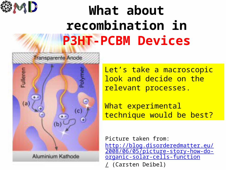
What about recombination in P3HT-PCBM Devices
Let’s take a macroscopic look and decide on the relevant processes.
What experimental technique would be best?
Picture taken from:http://blog.disorderedmatter.eu/2008/06/05/picture-story-how-do-organic-solar-cells-function/ (Carsten Deibel)
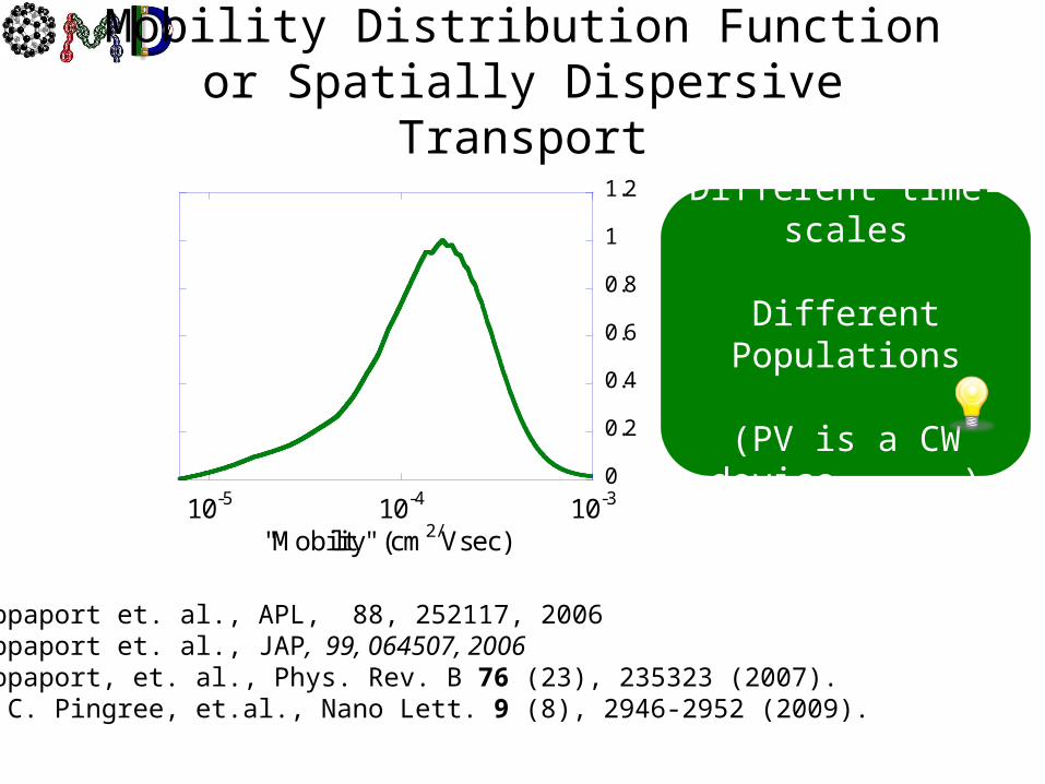
Mobility Distribution Functionor Spatially Dispersive Transport
N. Rappaport et. al., APL, 88, 252117, 2006N. Rappaport et. al., JAP, 99, 064507, 2006N. Rappaport, et. al., Phys. Rev. B 76 (23), 235323 (2007).L. S. C. Pingree, et.al., Nano Lett. 9 (8), 2946-2952 (2009).
Different time-scales
Different Populations
(PV is a CW device )
0
0.2
0.4
0.6
0.8
1
1.2
10-5 10-4 10-3
"Mobility" (cm2/Vsec)

Cell
Effici
ency
0.01 0.1 1 10 1000.25
0.3
0.35
0.4
0.45
0.5
0.55
Generating Power (mWcm-2)
HOMO
Glass
ITOPEDOT:PSS
CaAl
(If Undoped) Only Loss Mechanism
Is Exciton recombination(Intra, Inter, “pairs”,…)
Free-Charge Generation Efficiency
Other Losses Kick in
N. Tessler and N. Rappaport, JAP, vol. 96, pp. 1083-1087, 2004.
N. Rappaport, et. al., JAP, vol. 98, p. 033714, 2005.
QE as a function of excitation power

QE as a function of excitation powerLangevin /Bimolecular loss
N. Tessler and N. Rappaport, Journal of Applied Physics, vol. 96, pp. 1083-1087, 2004.
N. Rappaport, et. al., Journal of Applied Physics, vol. 98, p. 033714, 2005.
PC e hJ q E n q E p
A P
LI B np dq
Charge generation rate
Photo-current
Bimolecular recombination-current
hJ J n pe h e
No re-injection
Signature of bi-molecular Loss
Smaller Bimolecular Coefficient
0.65
0.7
0.75
0.8
0.85
0.9
0.95
1
1.05
1
1.2
1.4
1.6
1.8
2
10-3 10-2 10-1 100 101 102 103Nor
mal
ize
d Q
uant
um
Eff
icie
ncy
Loss P
ow
er-Law
Intensity [mW/cm2]
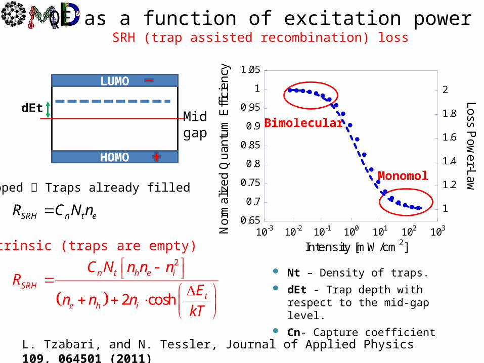
L. Tzabari, and N. Tessler, Journal of Applied Physics 109, 064501 (2011)
Nt – Density of traps. dEt - Trap depth with respect
to the mid-gap level. Cn- Capture coefficient
LUMO
HOMO
Mid gap
dEtBimolecular
Monomol
SRH n t eR C N n
Doped Traps already filled
2
2 cosh
n t h e i
SRHt
e h i
C N n n nR
En n n
kT
Intrinsic (traps are empty)
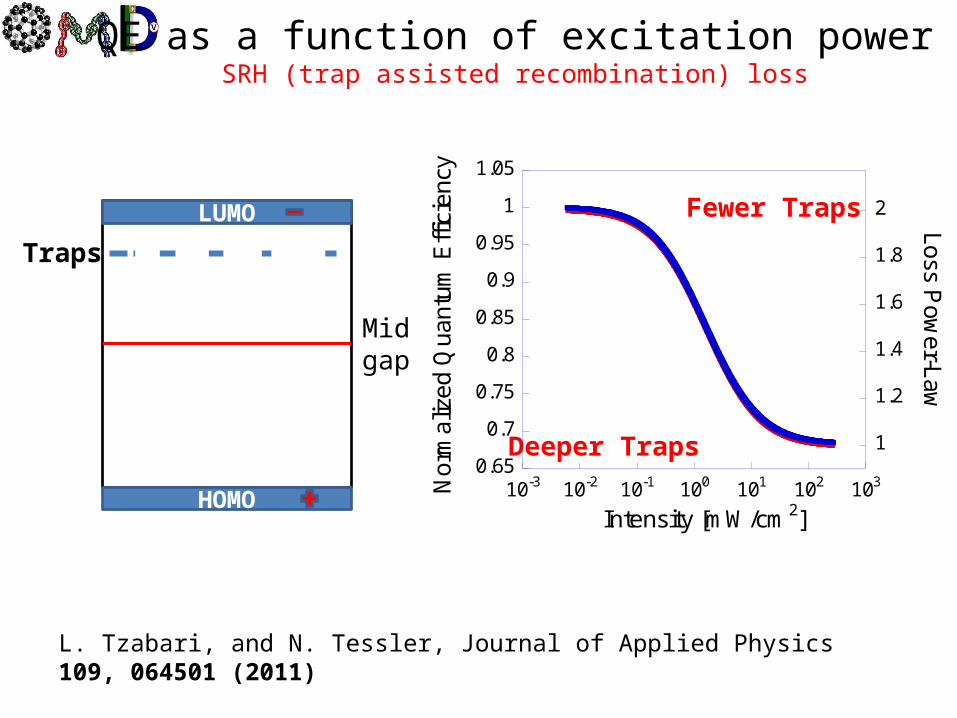
QE as a function of excitation powerSRH (trap assisted recombination) loss
0.65
0.7
0.75
0.8
0.85
0.9
0.95
1
1.05
1
1.2
1.4
1.6
1.8
2
10-3 10-2 10-1 100 101 102 103No
rmal
ized
Qua
ntu
m E
ffici
ency
Loss Po
wer-L
aw
Intensity [mW/cm2]
L. Tzabari, and N. Tessler, Journal of Applied Physics 109, 064501 (2011)
LUMO
HOMO
Mid gap
Traps
Fewer Traps
Deeper Traps
QE as a function of excitation powerSRH (trap assisted recombination) loss
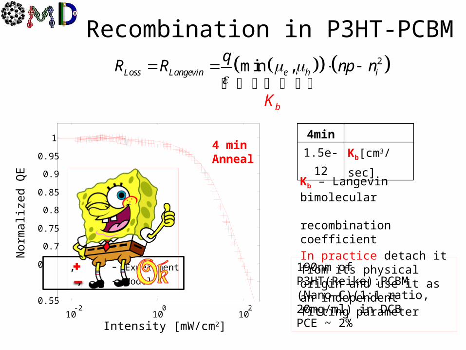
Recombination in P3HT-PCBM 2min ,Loss Langevin e h i
b
qR R p n
K
n
4min
1.5e-12 Kb[cm3/sec]
10-2
100
102
0.55
0.6
0.65
0.7
0.75
0.8
0.85
0.9
0.95
14 minAnneal
, - Experiment
, - Model
Intensity [mW/cm2]
Nor
mal
ized
QE
Kb – Langevin bimolecular recombination coefficientIn practice detach it from its physical origin and use it as an independent fitting parameter
190nm of P3HT(Reike):PCBM (Nano-C)(1:1 ratio, 20mg/ml) in DCB PCE ~ 2%
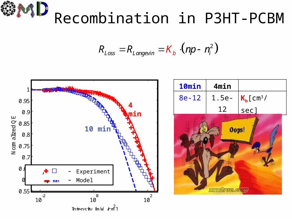
Recombination in P3HT-PCBM
10min 4min
8e-12 1.5e-12 Kb[cm3/sec]
10-2
100
102
0.55
0.6
0.65
0.7
0.75
0.8
0.85
0.9
0.95
1
Intensity [mW/cm2]
Nor
mal
ize
d Q
E
4 min
10 min
, - Experiment
, - Model
2Loss Langev bin inKR R np

Shockley-Read-Hall Recombination
LUMO
HOMO
Mid gap
0.5
0.6
0.7
0.8
0.9
1
1.1
10-2 10-1 100 101 102 103Nor
mal
ized
Qua
ntum
Effi
cien
cy
Intensity [mW/cm^2]
, - Experiment
, - Model
4 min
10 min
L. Tzabari and N. Tessler, "JAP, vol. 109, p. 064501, 2011.
dEt
2
2 cosh
n t h e i
SRHt
e h i
C N n n nR
En n n
kT
Intrinsic (traps are empty)
I. Ravia and N. Tessler, JAPh, vol. 111, pp. 104510-7, 2012. (P doping < 1012cm-3)

10-2
100
102
0.5
0.6
0.7
0.8
0.9
1
Intensity [mW/cm2]
Nor
ma
lize
d Q
E
Shockley-Read-Hall + Langevin
10min 4min1.2e17 1.9e17 Nt [1/cm3]0.371 0.435 dEt [eV]
0.5e-12 0.5e-12 Kb[cm3/sec]
4 min
10 min
, - Experiment
, - Model
LUMO
HOMO
Mid gap
dEt
The dynamics of recombination at the interface
is both SRH and Langevin
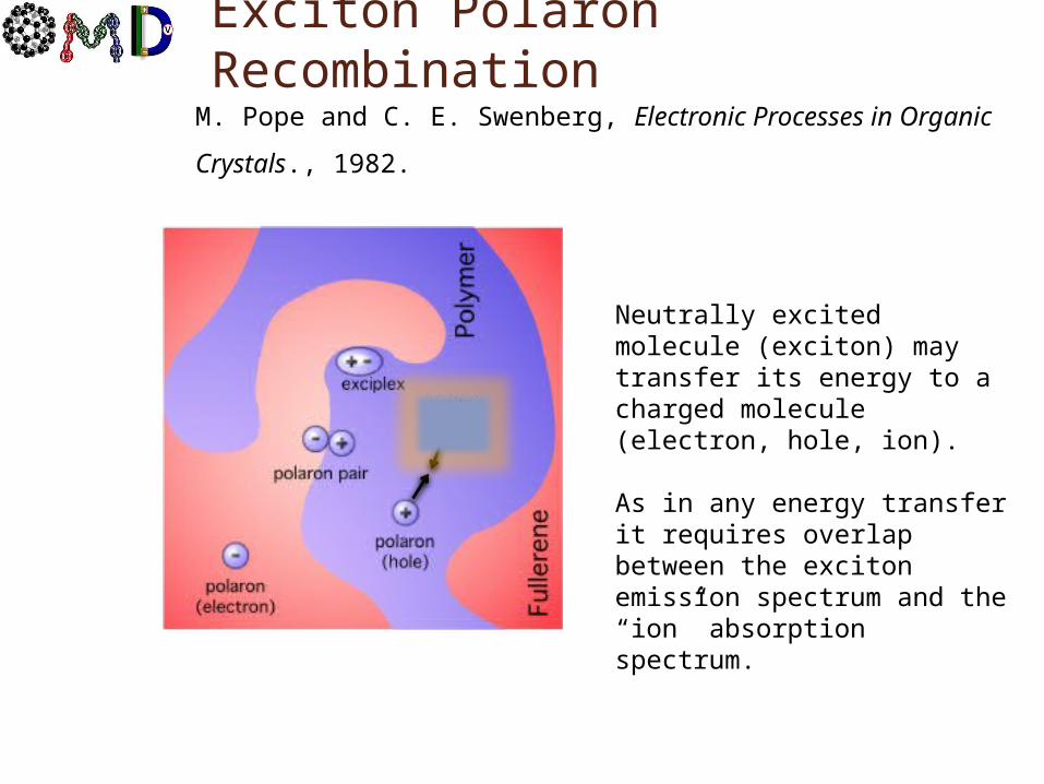
Exciton Polaron Recombination
Neutrally excited molecule (exciton) may transfer its energy to a charged molecule (electron, hole, ion).
As in any energy transfer it requires overlap between the exciton emission spectrum and the “ion” absorption spectrum.
M. Pope and C. E. Swenberg, Electronic Processes in Organic Crystals., 1982.

A. J. Ferguson, N. Kopidakis, S. E. Shaheen and G. Rumbles, J Phys Chem C 112 (26), 9865, 2008
Quenching of Excitons by Holes in P3HT Films
In neat P3HT ramping the excitation power results in exciton-exciton annihilation
Add 1% PCBM and losses become dominated by Exciton-Polaron recombination.
Excitation Density
Gen
erat
ed C
harg
e D
ensi
ty (a
t t=0
)
Kep=3x10⁻⁸ cm3/s

Exciton Polaron Recombination
Nt – Density of traps. dEt - trap depth with
respect to the mid-gap level.
Kep – Exciton polaron recombination rate.
Kd– dissociation rate 1e9-1e10 [1/sec]
Sensitivity 10min 4min
0 1.05e17 1.9e17 Nt [1/cm^3]
0.015 0.365 0.435 dEt [eV]
1.08e-8 1.6e-8 1.6e-8 Kep[cm^3/sec]
Exciton-polaron recombination rate
exex d ep ex pl
ex
nG n K V K n n
0.5
0.6
0.7
0.8
0.9
1
1.1
10-2 10-1 100 101 102 103No
rmal
ized
Qua
ntu
m E
ffic
ienc
y
Intensity [mW/cm^2]
4 minutes
10 minutes , - Experiment
, - Model
A. J. Ferguson, et. al., J Phys Chem C, vol. 112, pp. 9865-9871, 2008 (Kep=3e-8)
J. M. Hodgkiss, et. al., Advanced Functional Materials, vol. 22, p. 1567, 2012. (Kep=1e-8)

T. A. Clarke, M. Ballantyne, J. Nelson, D. D. C. Bradley, and J. R. Durrant, "Free Energy Control of Charge Photogeneration in Polythiophene/Fullerene Solar Cells: The Influence of Thermal Annealing on P3HT/PCBM Blends," Advanced Functional Materials, vol. 18, pp. 4029-4035, 2008. (~50meV stabilization)
0.5
0.6
0.7
0.8
0.9
1
1.1
10-2 10-1 100 101 102 103No
rmaliz
ed Q
uan
tum
Eff
icie
ncy
Intensity [mW/cm^2]
4 minutes
10 minutes
Sensitivity 10min 4min
0 1.05e17 1.9e17 Nt [1/cm^3]
0.015 0.365 0.435 dEt [eV]
1.08e-8 1.6e-8 1.6e-8 Kep[cm^3/sec]
Traps or CT states are stabilized during annealing

What does it all mean(summary, conclusions,…)
5. Charge generation requires some field and this is observed at very low light intensities
1. The “geminate” recombination occurs through “defect sites” and their availability limits the recombination.
2. “Defect sites” or “Traps” act like stabilized charge transfer states.
3. At high enough density (depending on morphology) a new channel opens up and Losses become Bi-molecular.
4. Bi-molecular = electron-hole or exciton-polaron?
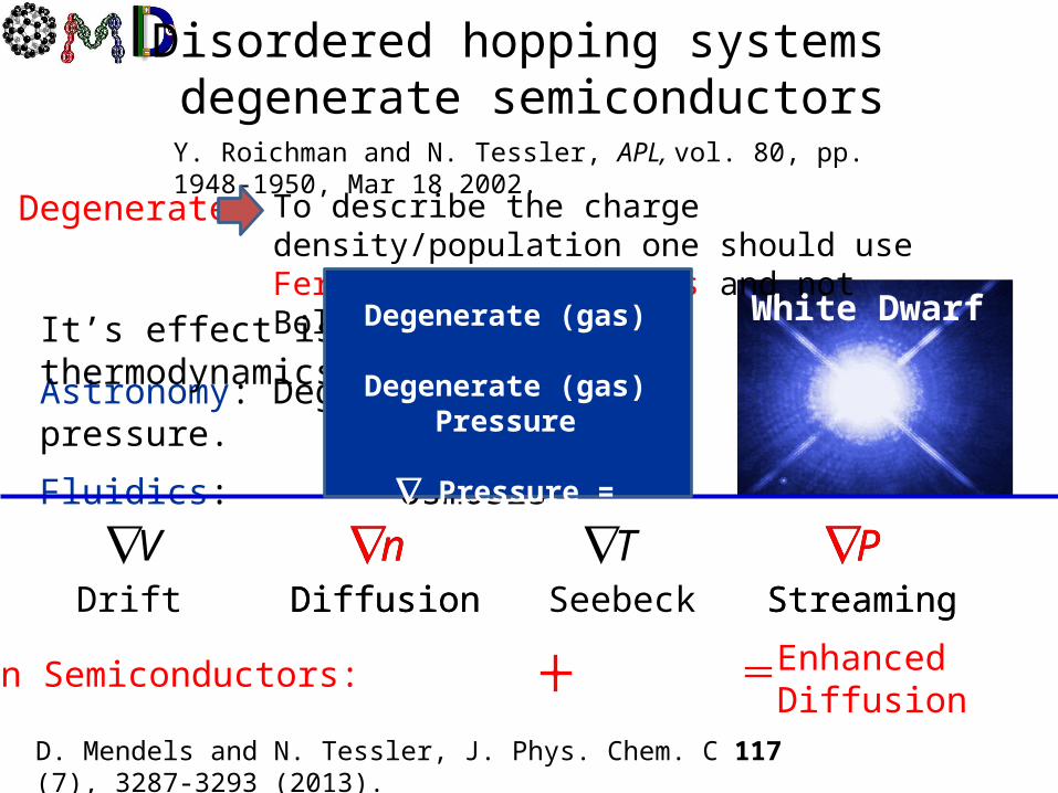
Disordered hopping systems degenerate semiconductors
Y. Roichman and N. Tessler, APL, vol. 80, pp. 1948-1950, Mar 18 2002.
White Dwarf
Astronomy: Degenerate gas pressure.
Fluidics: Osmosis
To describe the charge density/population one should use Fermi-Dirac statistics and not Boltzmann
Degenerate
It’s effect is in basic thermodynamics texts.
VDrift
nDiffusion
TSeebeck
PStreaming
In Semiconductors:
nDiffusion
PStreaming
Enhanced Diffusion
D. Mendels and N. Tessler, J. Phys. Chem. C 117 (7), 3287-3293 (2013).
Degenerate (gas)
Degenerate (gas) Pressure
Pressure = Enhanced Diff.
Thank You
21
Israeli Nanothecnology Focal Technology Area on "Nanophotonics for Detection"
Ministry of Science, Tashtiyot program
Helmsley project on Alternative Energy of the Technion, Israel Institute of Technology, and the Weizmann Institute of Science
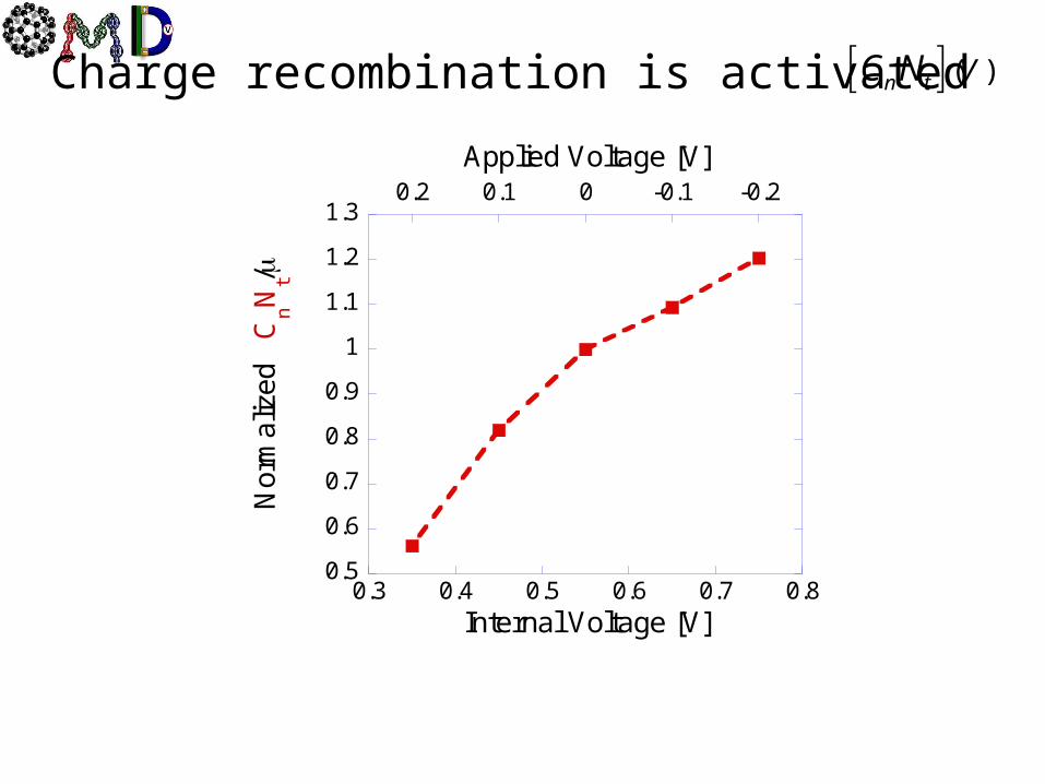
0.5
0.6
0.7
0.8
0.9
1
1.1
1.2
1.3
0.3 0.4 0.5 0.6 0.7 0.8
-0.2-0.100.10.2
Internal Voltage [V]
Applied Voltage [V]
Nor
mal
ized
C
nN
t/
Charge recombination is activated ( )n t VC N
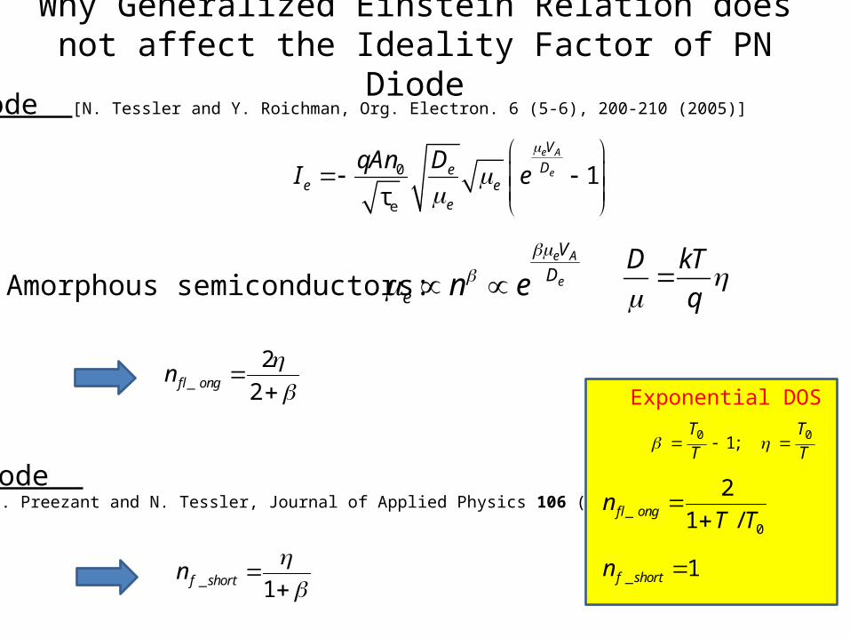
Why Generalized Einstein Relation does not affect the Ideality Factor of PN Diode
0
e
1τ
e A
e
V
Dee e
e
qAn DI e
In Amorphous semiconductors:e A
e
V
De n e
D kT
q
_
2
2f longn
Long Diode [N. Tessler and Y. Roichman, Org. Electron. 6 (5-6), 200-210 (2005)]
Short Diode [Y. Vaynzof, Y. Preezant and N. Tessler, Journal of Applied Physics 106 (8), 6 (2009)]
_ 1f shortn
0 01;
T T
T T
Exponential DOS
_0
2
1 /f longnT T
_ 1f shortn