Embed Size (px)
Citation preview

Generating Multiple Phase Coherent Signals – Aligned in Phase and Time Application Note
Products:
| R&SSMW200A
| R&SSGT100A
| R&SSGS100A
| R&SSGU100A
| R&SSMBV100A
Rohde & Schwarz signal generators present a compact easy-to-use solution for generating phase coherent signals. Different generator models can be coupled to optimally fit user requirements in terms of number of phase coherent channels and RF frequency range. This application note explains how to generate phase coherent signals, details what to consider and how to best calibrate the relative phases and timing between the individual channels. This document also presents various measurements of the phase stability over time for different RF frequencies.
Note: Please find the most up-to-date document on our homepage http://www.rohde-schwarz.com/appnote/1GP108.
App
licat
ion
Not
e
C. T
röst
er-S
chm
id
T. B
edno
rz
01.2
016 –
1GP
108_
0E
App
licat
ion
Not
e
C. T
röst
er-S
chm
id
T. B
edno
rz
09.2
016 –
1GP
108_
1E

Table of Contents
1GP108_1E Rohde & Schwarz Generating Multiple Phase Coherent Signals – Aligned in Phase and Time 2
Table of Contents
1 Note ......................................................................................... 5
2 Introduction ............................................................................ 5
3 Background ............................................................................ 6
3.1 What is phase coherence? .......................................................................... 6
3.2 Methods to stabilize the relative phase of two RF carriers ...................... 6
3.2.1 Level 1 – 10 MHz REF coupling................................................................... 7
3.2.2 Level 2 – 1 GHz REF coupling ..................................................................... 8
3.2.3 Level 3 – LO coupling .................................................................................. 8
3.3 RF phase control .......................................................................................... 9
3.3.1 1 GHz REF coupling ..................................................................................... 9
3.3.2 LO coupling .................................................................................................10
4 The Right Instrument ........................................................... 12
4.1 Phase coherence option B90/K90.............................................................12
4.2 What else is of importance? ......................................................................13
5 Example Setups ................................................................... 15
5.1 8-channel system up to 6 GHz ..................................................................15
5.2 4-channel system up to 20 GHz ................................................................16
6 What to Consider? ............................................................... 18
6.1 Temperature ................................................................................................18
6.2 Cabling ........................................................................................................19
6.3 LO distribution ............................................................................................20
6.4 Vibration/shock...........................................................................................21
6.5 RF frequency...............................................................................................21
6.6 RF level ........................................................................................................21
7 How To Configure? .............................................................. 24
7.1 How to configure LO coupling ..................................................................24
7.2 How to set the phase in the baseband .....................................................25
7.3 How to compensate delays .......................................................................26
7.4 How to change the RF level .......................................................................27
7.4.1 How to lock the attenuator position .........................................................28

Table of Contents
1GP108_1E Rohde & Schwarz Generating Multiple Phase Coherent Signals – Aligned in Phase and Time 3
7.4.2 How to set the digital attenuation .............................................................28
8 Calibration – Phase and Time Alignment ........................... 30
8.1 Phase alignment .........................................................................................30
8.2 Time alignment ...........................................................................................31
8.2.1 Prerequisite: baseband synchronization .................................................32
8.2.2 Time alignment principle ...........................................................................33
9 Calibration – How To Do ...................................................... 35
9.1 General procedure .....................................................................................35
9.2 How to generate the calibration signals ..................................................35
9.2.1 How to generate a CW signal via the baseband ......................................35
9.2.2 How to generate a FM chirp signal ...........................................................36
9.3 How to determine the RF level to be used for calibration ......................36
9.4 Phase alignment for CW signals...............................................................37
9.4.1 Using a vector network analyzer ..............................................................38
9.4.2 Using a spectrum analyzer ........................................................................39
9.4.3 Using an oscilloscope ...............................................................................40
9.5 Phase and time alignment for I/Q modulated signals.............................41
9.5.1 Basic information about the VNA .............................................................42
9.5.1.1 Block diagram of a VNA .............................................................................42
9.5.1.2 Measuring the relative phase between two signals ................................43
9.5.2 Calibration of the VNA ...............................................................................44
9.5.3 Measuring the phase between two chirp signals ....................................46
9.5.4 Step-by-step guide for the phase and time alignment ...........................49
9.5.4.1 Step 1 - General VNA settings ...................................................................49
9.5.4.2 Step 2 - Calibration of the VNA .................................................................51
9.5.4.3 Step 3 – Measuring the phase between the chirp signals .....................52
10 Calibration – When To Repeat ............................................ 54
10.1 When to repeat the calibration?................................................................54
10.2 Reproducibility ...........................................................................................55
11 Measurement Results for Phase Stability .......................... 56
11.1 Pretest .........................................................................................................56
11.2 2 GHz run .....................................................................................................57
11.3 10 GHz run ...................................................................................................58

Table of Contents
1GP108_1E Rohde & Schwarz Generating Multiple Phase Coherent Signals – Aligned in Phase and Time 4
11.4 20 GHz run ...................................................................................................59
11.5 40 GHz run ...................................................................................................60
11.6 10 hour run ..................................................................................................61
11.7 LO versus 1 GHz REF coupling ................................................................62
12 Quick Guide .......................................................................... 64
13 How to Improve the Phase Stability of a Phase Coherent System .................................................................................. 65
14 Special Applications ............................................................ 67
14.1 Phase coherence at very low RF frequencies .........................................67
14.2 Phase coherence for multichannel setups with different RF frequencies
......................................................................................................................68
15 Appendix ............................................................................... 70
15.1 List of possible multichannel setups .......................................................70
16 Abbreviations ....................................................................... 71
17 References ............................................................................ 72
18 Ordering Information ........................................................... 72

Note
1GP108_1E Rohde & Schwarz Generating Multiple Phase Coherent Signals – Aligned in Phase and Time 5
1 Note The following abbreviations are used in this application note for Rohde & Schwarz
products:
The R&S®SMW200A vector signal generator is referred to as SMW.
The R&S®SMBV100A vector signal generator is referred to as SMBV.
The R&S®SGT100A SGMA vector RF source is referred to as SGT.
The R&S®SGS100A SGMA RF source is referred to as SGS.
The R&S®SGU100A SGMA upconverter is referred to as SGU.
The R&S®SGMA-GUI PC software is referred to as SGMA-GUI.
The R&S®SGU-Z4 connection kit R&S
®SGU100A to R&S
®SGS100A is
referred to as SGU-Z4.
Instrument options, e.g. R&S®SMW-B90 are referred to as B90.
The R&S®ZVA vector network analyzer is referred to as ZVA.
2 Introduction Testing multi-antenna systems such as phased array or beamforming antennas
requires a test system capable of providing multiple signals with constant phase
relationships between them. The coherent test signals must have a specific or
definable phase difference (relative phase) and definable amplitude. Some of the
challenges for such a test system include compactness, phase control capability and
simplicity in handling. In particular, phase stability between the channels is of
importance. Many applications in the A & D direction finding and mobile
communications beamforming sectors demand that the phase relationships between
channels be constant over time with minimal deviations, for example as little as < 1°
phase drift. Such high phase stability can only be achieved when using a common
synthesizer signal (local oscillator, LO) for all signal generators in a test system.
Rohde & Schwarz signal generators present a compact easy-to-use solution for
generating phase coherent signals. The generators’ phase coherence option enables
LO coupling of multiple instruments by distributing the synthesizer signal of one
instrument to the others. Different generator models can be coupled to optimally fit
user requirements in terms of number of phase coherent channels and RF frequency
range. The Rohde & Schwarz solution is therefore flexible and scalable.
This application note explains how to generate phase coherent signals. It gives some
background on the technical requirements of the test and measurement equipment and
presents some recommended test solutions. It details what to consider and how to
configure the test setup. Furthermore, this application note describes in detail how to
best calibrate the relative phases and timing between the individual channels and
when to repeat the calibration. This document also presents several measurements of
the phase stability over time for different RF frequencies. It closes with a quick guide
summarizing the most important steps and points and an appendix summarizing the
various setups for generating phase coherent signals.

Background
1GP108_1E Rohde & Schwarz Generating Multiple Phase Coherent Signals – Aligned in Phase and Time 6
t
t
RF 1
RF 2
3 Background
3.1 What is phase coherence?
Two signals are phase coherent if they maintain a fixed phase relationship with each
other. In other words, if the relative phase between the two signals stays constant
over time.
Besides this general definition, there is also a more strict definition where phase
coherence is only defined for continuous wave (CW) carriers with equal frequencies or
for CW carriers whose frequencies are multiples of each other. Again, these CW
carriers are phase-coherent if there is a defined and stable phase relationship between
them.
3.2 Methods to stabilize the relative phase of two RF
carriers
In the following, we consider two RF signal generators. Both synthesizers have their
own built-in reference oscillator. Alternatively, they can use an external reference
frequency signal from an external source. In both cases, the resulting synthesizer
signal is generated in several steps from the reference signal using phase locked loops
(PLL).
Unless countermeasures are taken, the relative phase of the RF signals changes
unpredictably over time. The RF frequencies may also differ slightly, e.g. by tens of a
Hertz at 1 GHz.

Background
1GP108_1E Rohde & Schwarz Generating Multiple Phase Coherent Signals – Aligned in Phase and Time 7
3.2.1 Level 1 – 10 MHz REF coupling
If the two signal generators are coupled via a common 10 MHz reference signal, they
generate identical RF frequencies. However, the instantaneous relative phase is
instable and the long term stability is poor.
This is due to the following factors:
1) Phase noise of the two synthesizers is uncorrelated in time.
2) “Weak” coupling at 10 MHz. For example, if the phase drifts by 0.1° in the
10 MHz reference PLL (due to effects such as offset drifts of the phase
detector), the RF phase at 1 GHz will drift by 10°.
3) Drifts in other components of the signal generation chain such as the
DACs, the I/Q modulator, the power amplifier and the electronic step
attenuator.
4) Temperature differences that cause a change of the effective electrical
length of some synthesizer components. This leads to a thermal phase
drift between the two synthesizers.
As a consequence, 10 MHz reference coupling cannot guarantee phase coherence of
the RF signals with good long term stability.
Time
Time

Background
1GP108_1E Rohde & Schwarz Generating Multiple Phase Coherent Signals – Aligned in Phase and Time 8
3.2.2 Level 2 – 1 GHz REF coupling
If the two signal generators are coupled via a common 1 GHz reference signal, the
long term stability is greatly improved. Now, if the phase drifts by 0.1° in the 1 GHz
reference PLL, the RF phase at 1 GHz will drift by only 0.1°. However, the relative
phase is not fully stable due to the same factors as listed for the 10 MHz coupling.
As a consequence, 1 GHz reference coupling enables phase coherence of the RF
signals with reasonable long term stability.
3.2.3 Level 3 – LO coupling
Because factors 1) and 2) are very dominant, there is only one way to optimize the
phase stability of the two signal generators, namely to use a common synthesizer. This
means, the local oscillator (LO) signal of one synthesizer is used in both signal
generators.
Time
Time
Background
1GP108_1E Rohde & Schwarz Generating Multiple Phase Coherent Signals – Aligned in Phase and Time 9
Using a common synthesizer eliminates the factors 1), 2) and 4). Factor 3) remains.
LO coupling enables phase coherence of the RF signals with very good long term
stability. It is the best way to stabilize the relative phase of two RF carriers.
3.3 RF phase control
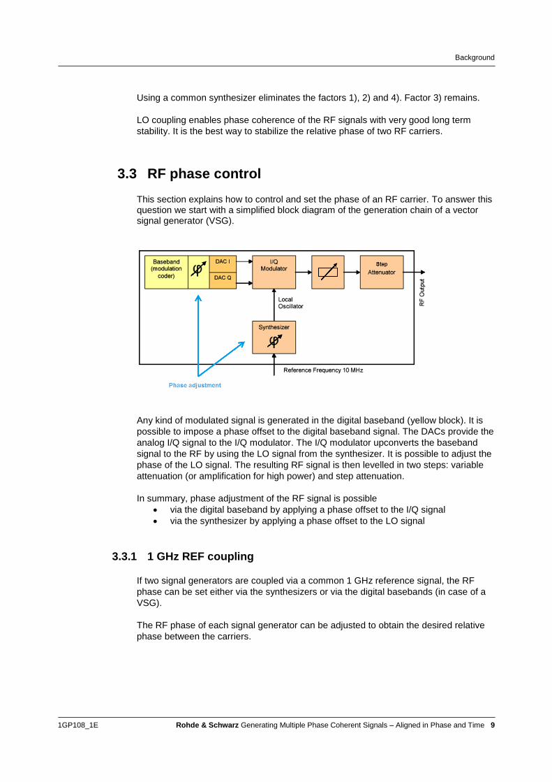
This section explains how to control and set the phase of an RF carrier. To answer this question we start with a simplified block diagram of the generation chain of a vector signal generator (VSG).
Any kind of modulated signal is generated in the digital baseband (yellow block). It is
possible to impose a phase offset to the digital baseband signal. The DACs provide the
analog I/Q signal to the I/Q modulator. The I/Q modulator upconverts the baseband
signal to the RF by using the LO signal from the synthesizer. It is possible to adjust the
phase of the LO signal. The resulting RF signal is then levelled in two steps: variable
attenuation (or amplification for high power) and step attenuation.
In summary, phase adjustment of the RF signal is possible
via the digital baseband by applying a phase offset to the I/Q signal
via the synthesizer by applying a phase offset to the LO signal
3.3.1 1 GHz REF coupling
If two signal generators are coupled via a common 1 GHz reference signal, the RF
phase can be set either via the synthesizers or via the digital basebands (in case of a
VSG).
The RF phase of each signal generator can be adjusted to obtain the desired relative
phase between the carriers.

Background
1GP108_1E Rohde & Schwarz Generating Multiple Phase Coherent Signals – Aligned in Phase and Time 10
3.3.2 LO coupling
If two signal generators are coupled via a common LO signal, the relative phase can
no longer be set via the synthesizers.
The RF phase of the signal generator which acts as LO master can still be adjusted via
the synthesizer but this setting will also be applied to the signal generator which acts
as LO slave. Setting the RF phases independently is not possible because of the
common synthesizer.

Background
1GP108_1E Rohde & Schwarz Generating Multiple Phase Coherent Signals – Aligned in Phase and Time 11
To obtain a desired relative phase between the carriers the phase adjustment must be
done via the digital baseband of a VSG.
As a consequence, CW signals must be generated via the baseband in order to be
able to set the phase individually for each RF carrier. These (pseudo) CW signals can
be generated by using DC signals for I and Q (see section 9.2.1 for details).

The Right Instrument
1GP108_1E Rohde & Schwarz Generating Multiple Phase Coherent Signals – Aligned in Phase and Time 12
4 The Right Instrument
4.1 Phase coherence option B90/K90
Changing the phase individually for each RF carrier is mandatory for phase coherence applications. In addition, LO coupling is the preferred method to assure stable relative phases. Consequently, VSGs with LO coupling capability are ideal.
Rohde & Schwarz signal generators present a very compact and easy-to-use solution
for generating phase-coherent RF signals with best long term stability. The generators
can be equipped with a special phase coherence option that enables LO coupling of
multiple instruments by distributing the synthesizer signal of one instrument to the
others. This way, multiple I/Q modulators can be driven by the same LO signal.
Different generator models can be coupled to optimally fit user requirements in terms
of number of phase coherent carriers and RF frequency range. The B90/K90 option is
available for the following instruments:
Instruments with phase coherence option
Instrument Type Option Max RF Freq. RF outputs 1 GHz REF
SMW VSG B90 40 GHz
1 or 2
+ external RFs
no
SMBV VSG B90 6 GHz 1 no
SGT VSG K90 6 GHz 1 yes
SGS VSG (without
internal baseband)
K90 12.75 GHz
40 GHz with SGU
1 yes
The B90/K90 option is not available for analog signal generators, because they lack
the possibility to set the phases individually for each RF carrier when LO coupling is
used.
The B90/K90 option has a lower frequency limit of 200 MHz for SMW and SMBV and
80 MHz for SGT and SGS (see also the instruments’ datasheets).
Example setup: four-channel system up to 20 GHz
For example, generating four phase-coherent RF signals up to 20 GHz requires one
SMW (two-channel instrument) and two sets of SGS/SGU (serving as external RF
outputs). The whole setup acts as one unit, conveniently controlled via the intuitive
SMW touchscreen. The SMW generates two 20 GHz phase-coherent channels and
also provides the I/Q baseband signals and the LO signal for the two external RF
outputs. The relative phases between all four RF channels are set digitally in the
baseband on the SMW.

The Right Instrument
1GP108_1E Rohde & Schwarz Generating Multiple Phase Coherent Signals – Aligned in Phase and Time 13
4.2 What else is of importance?
For the majority of phase coherence applications, a signal generator or a set of signal generators need to offer the following capabilities:
Generation of multiple phase coherent RF carriers
Generation of correctly coded baseband signals, one for each RF output
Generation of time synchronous RF signals
Possibility to set phase, level and time offsets for all RF signals individually, ideally in realtime without signal interruption.
Especially the generation of highly synchronous RF test signals is difficult. Synchronizing multiple signal sources is always a challenge. In addition, time offsets of external components such as cables need to be compensated.

The Right Instrument
1GP108_1E Rohde & Schwarz Generating Multiple Phase Coherent Signals – Aligned in Phase and Time 14
(“wv” stands for waveform)
The SMW meets all these requirements:
SMW for phase coherence applications
Requirement SMW feature Details
Generation of multiple RF
signals
2 internal RF outputs
+ connection of external RF outputs
up to 2 SGS
up to 2 SGS/SGU combinations
up to 6 SGT
See reference [1]
Phase coherence between
RF carriers
LO coupling between SMW RFs and external RFs See section 4.1
Individual baseband
signals for each RF output
SMW-K76 option for generation of up to eight
baseband signals (e.g. ARB) from a single SMW
See section 5.1
Synchronous baseband
signals
One common baseband section for all baseband
signals with inherent synchronization
See section 8.2.1
Settable phase Baseband phase offset for each baseband signal.
Settable in realtime.
See section 7.2
Settable level RF step attenuator and settable digital attenuation
for each RF output. Settable in realtime.
See section 7.4
Settable time delay
Global trigger offset;
Digital time delay for each RF signal. Settable in
realtime.
See section 7.3

Example Setups
1GP108_1E Rohde & Schwarz Generating Multiple Phase Coherent Signals – Aligned in Phase and Time 15
5 Example Setups The Rohde & Schwarz test solution is scalable to optimally meet customer needs. The
number and type of generators needed depends on the required number of phase-
coherent channels and RF frequency.
This section presents some example setups in more detail. It focuses on setups with
the SMW. For a more comprehensive list of possible setups, please refer to the
appendix of this document.
The following table lists some test setups for generating phase-coherent channels. The
small form factor and easy handling of the test setups are unique on the market. The
generators are conveniently controlled via one user interface. Their compact size and
excellent phase stability make these multichannel setups the ideal test solution.
5.1 8-channel system up to 6 GHz
The K76 option enables the SMW to generate eight time-synchronized baseband signals from its two internal baseband generators – with individual phase offsets for each baseband signal. In combination with six SGTs (serving as external RF outputs), the SMW setup generates eight phase-coherent RF signals up to 6 GHz.
The SMW provides the I/Q baseband signals and the LO signal for the six external RF
outputs. The SGTs are connected via the digital I/Q interface. The relative phases
between all eight RF channels are set digitally in the baseband on the SMW (indicated
by the -sign – see section 7.2 for details). The maximum RF bandwidth for each
signal is 80 MHz.

Example Setups
1GP108_1E Rohde & Schwarz Generating Multiple Phase Coherent Signals – Aligned in Phase and Time 16
The required system configuration on the SMW is 8 x 1 x 1.
Each baseband signal (stream) is routed to a separate output (e.g. digital output
“BBMM1”) in the IQ stream mapper. The whole setup acts as one unit, conveniently
controlled via the intuitive SMW touchscreen. How to connect the SGTs is described in
detail in reference [1].
For detailed information about the required instrument options for this setup please
refer to reference [6].
Side note: An 8-channel system up to 6 GHz can also be implemented using eight
SGTs stand-alone. The instruments can be coupled to provide time-synchronized
baseband signals at a maximum RF bandwidth of 240 MHz for each signal. This
solution is ARB-based and controlled by the external software SGMA GUI (see
reference [1]).
5.2 4-channel system up to 20 GHz
The SMW in combination with two sets of SGS/SGU (serving as external RF outputs)
generates four phase-coherent RF signals up to 20 GHz.
The SMW provides the I/Q baseband signals and the LO signal for the two external RF
outputs. The SGS/SGU sets are connected via the analog I/Q interface. The relative
phases between all RF channels are set digitally in the baseband on the SMW. The
maximum RF bandwidth for each signal is 160 MHz.

Example Setups
1GP108_1E Rohde & Schwarz Generating Multiple Phase Coherent Signals – Aligned in Phase and Time 17
The required system configuration on the SMW is 4 x 1 x 1.
Each baseband signal (stream) is routed to a separate output in the IQ stream mapper.
The whole setup acts as one unit, conveniently controlled via the intuitive SMW
touchscreen. How to connect the SGS/SGU sets is described in detail in reference [1].
For detailed information about the required instrument options for this setup please
refer to reference [6].
What to Consider?
1GP108_1E Rohde & Schwarz Generating Multiple Phase Coherent Signals – Aligned in Phase and Time 18
6 What to Consider?
6.1 Temperature
Temperature has a significant effect on the phase. If the temperature of the signal
generator changes, the phases will change due to drifts in electronic components and
changes of the electrical length of cables and conductor paths. To achieve low phase
drift, constant temperature must be ensured.
1) The instrument needs to warm up for at least 30 minutes after startup.
2) The ambient temperature and the internal temperature of the instrument
correlate very well. The internal temperature reacts linearly to changes of the
ambient temperature. Therefore, the ambient temperature must be kept
constant.
Hint: The internal temperature of the instrument can be queried remotely to monitor the
temperature trend. The SCPI command DIAGnostic:POINt:CATalog? returns the
test points available in the instrument. (A detailed description of the test points can be
found in the service manual.) For example, the temperature can be queried with the
following SCPI commands:
SMW: DIAGnostic:POINt? “MWOPU_TEMP_DB2” or
DIAGnostic:POINt? “RFOPU_TEMP_CELSIUS”
SGS: DIAGnostic:POINt? “D_TEMP_RFB”
SGT: DIAGnostic:POINt? “D_TEMP_RFB”
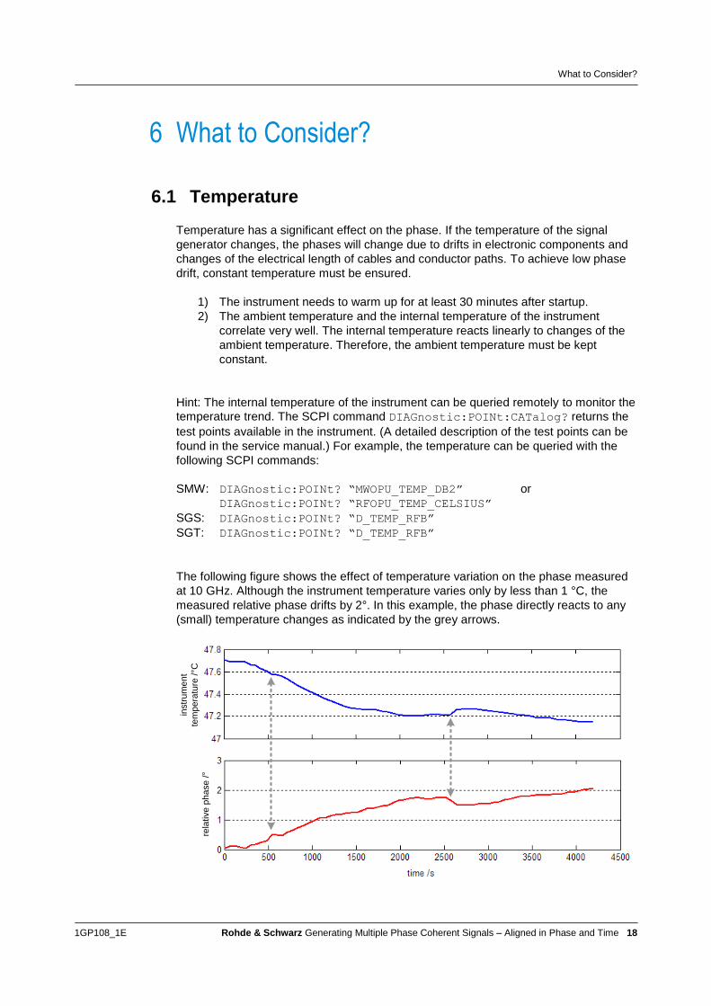
The following figure shows the effect of temperature variation on the phase measured
at 10 GHz. Although the instrument temperature varies only by less than 1 °C, the
measured relative phase drifts by 2°. In this example, the phase directly reacts to any
(small) temperature changes as indicated by the grey arrows.
rela
tive
ph
ase
/°
instr
um
en
t
tem
pe
ratu
re /
°C

What to Consider?
1GP108_1E Rohde & Schwarz Generating Multiple Phase Coherent Signals – Aligned in Phase and Time 19
The temperature effect increases with higher RF frequencies and cable/line lengths.
Background:
The phase change in a coaxial cable can be expressed by the following equation:
c
lf r
360
Where f is the RF signal frequency, l is the physical cable length, c is the vacuum
speed of light and εr is the relative permittivity of the dielectric medium of the
cable.
The electrical length is given by rl . Both, the physical length and the relative
permittivity are sensitive to temperature variations. The physical length varies due
to thermal expansion. The relative permittivity varies in a nonlinear manner and
differently for different materials. Please see reference [2] for details. This means,
for a given temperature change the resulting phase change will be more
significant the higher the RF frequency is and the longer the total cable/line length
is.
For example, consider an LO connection cable of 50 cm initial length. The RF
frequency shall be 5 GHz. The initial temperature shall be room temperature and vary
by +1 °C. Assuming the temperature increase will lead to an increase of the electrical
length of 0.1 %, i.e. 0.5 mm, this will lead to a phase change along the cable of 3°.
A phase change on the LO signals impacts directly the relative phase between the two
LO-coupled RF signals. If the LO connection cable is 20 cm shorter, the phase change
will be only 1.8° in above example calculation. Short cables help significantly to reduce
temperature-induced phase drift.
Typical microwave cables have PTFE as dielectric medium. The electrical length of
PTFE varies with temperature exhibiting a significant kink around room temperature.
This so-called teflonTM
knee augments phase drifts when operating cables at
temperatures between 15 °C and 32 °C. For this reason it can be beneficial to operate
the setup in a temperature-stabilized environment above 32 °C, e.g. in a closed heated
rack or a temperature controlled chamber. Please see e.g. reference [2] for details on
the temperature dependence of PTFE.
6.2 Cabling
The use of suitable cables for LO and RF signals is very important. It is absolutely
mandatory to use phase stable cables.
Whenever possible the use of semi-rigid cables is recommended. Semi-rigid cables
are coaxial cables with a solid copper outer sheath. The cables are not very flexible
and not intended to be flexed after initial forming.

What to Consider?
1GP108_1E Rohde & Schwarz Generating Multiple Phase Coherent Signals – Aligned in Phase and Time 20
Whenever a flexible cable is needed, the use of R&S test cables (network analyzer
accessories), e.g. R&SZV-Z195 is recommended.
In any case, the connection cables for LO and RF signals should be as short in length
as possible! In addition, the cables must be suitable for the intended RF frequency.
6.3 LO distribution
High phase stability among all RF carriers requires a common LO signal. The easiest
way to distribute the LO signal is by daisy-chaining. Each cascaded R&S instrument
amplifies the LO signal to maintain a proper LO signal level.
To be less prone to temperature effects, the LO signal frequency is always kept below
6.5 GHz (see the instrument’s datasheet for details). For example, in case of 40 GHz
RF output, the LO frequency is a factor of eight lower than the wanted RF frequency,
contributing to a better phase stability. The LO frequency is multiplied automatically by
the instruments.
Although a common LO signal minimizes the phase drifts between the RF carriers,
there are still drifts in other components of the signal generation chain such as the
DACs, the I/Q modulator, the power amplifier and the electronic step attenuator (i.e.
factor 3) from section 3.2.1 remains).
In addition, temperature effects on the LO connection cables remain. Temperature
changes cause a change of the effective electrical length of the cable. For this reason,
LO daisy-chaining has the disadvantage that the last instrument in the chain suffers
generally most from temperature induced phase drifts (because it has the longest
effective LO cable length). For optimal performance a symmetric setup may be used
with all LO connections having the same physical cable lengths. In this case, the LO
signal needs to be split and branched to all instruments. The LO level must be
maintained however. A passive splitter or distribution amplifier with reasonable
specifications should be used in this case.

What to Consider?
1GP108_1E Rohde & Schwarz Generating Multiple Phase Coherent Signals – Aligned in Phase and Time 21
6.4 Vibration/shock
Touching or bending flexible cables lead to a phase change. Any movement of the
cables needs to be avoided. If necessary, they can be fit into fixtures to prevent
movement. Vibrations and shocks must not impact the setup. For example, even slight
bumping against the test rack or bench will shake the flexible cables. Bending a cable
to rearrange it can easily change the phase by 3° for example. (High-quality cables
have a specification for phase stability when flexing is applied.)
6.5 RF frequency
1 GHz REF coupling
The RF frequency of each cascaded R&S signal generator can be set individually, i.e.
to different values.
LO coupling
The RF frequency of each cascaded R&S signal generator is coupled due to the
common LO signal. However, it is still important to set the right RF frequency on the
signal generators. They need the frequency information for setting the internal filters
correctly (e.g. harmonic filters) and for applying the correct internal correction data
(e.g. for frequency response compensation). Signal generators (SGT/SGS) controlled
by the SMW get the frequency information automatically from the SMW. On other
setups, the user needs to set the RF frequency to the same value on each signal
generator.
6.6 RF level
The RF level has a wide setting range (about 170 dB) achieved by using amplifiers, a
variable attenuator and a step attenuator.

What to Consider?
1GP108_1E Rohde & Schwarz Generating Multiple Phase Coherent Signals – Aligned in Phase and Time 22
The electronic step attenuator consists of various attenuators (with different
attenuation) and switches. Depending on the desired overall attenuation, the switches
are set such that the signal passes a certain set of attenuators. If the level is changed,
the switches are reset such that the signal passes a different set of attenuators. The
number of attenuators and switches passed by the signal varies for different levels.
This means the physical length of the signal path through the step attenuator varies
(mm to cm range). In addition, each switch along the signal path causes a significant
phase shift. As a consequence, as soon as the step attenuator position is altered the
phase of the RF signal is influenced significantly. (The phase change is not just a few
degrees but can be up to 360°).
Mechanical step attenuators have a simpler layout but it is a similar situation.
When the RF level is varied, the step attenuator changes its position about every 5 dB.
Within the coarse steps of the step attenuator the RF level is fine-adjusted by the
variable attenuator. To achieve the optimal RF performance with regard to noise and
harmonics the step attenuator position is changed quite often such that the variable
attenuator can operate at its optimum.
The position changes do not occur at fixed RF level settings but are determined during
instrument calibration and vary from instrument to instrument. It is therefore not reliably
predictable at which RF level settings the step attenuator will change its position.
To avoid these position changes the step attenuator position can be locked. In this
case the RF level can only be varied by means of the variable attenuator resulting in a
limited level range.
Varying the attenuation of the variable attenuator may result in a change of impedance
matching and consequently in a phase change. The phase change is only moderate. It
can be zero over a few dBs but it can also be some degrees.
There is also the possibility to vary the RF level via the baseband. Normally, the digital
I/Q signal is always leveled to full scale to achieve optimal RF performance with regard
to noise. However, it is possible to digitally attenuate the signal. In this case the phase
is not influenced at all. There is no phase change.

What to Consider?
1GP108_1E Rohde & Schwarz Generating Multiple Phase Coherent Signals – Aligned in Phase and Time 23
It is therefore the recommended method to vary the RF level in phase coherence
applications – provided the RF level change is not too significant: If the digital
attenuation is set very high, then the signal to noise ratio gets poor. This is because
the noise level stays constant but the signal level is significantly below the full scale
level and thus close to the noise floor.
The following table summarizes the three different modes to control the RF level.
RF level adjustment – impact on RF phase
Attenuation type Influence on phase
Step attenuator
(Attenuator mode: Auto)
high
Variable attenuator (fixed step attenuator)
(Attenuator mode: Fixed)
moderate
Digital attenuation
(Attenuator mode: Auto or Fixed)
none

How To Configure?
1GP108_1E Rohde & Schwarz Generating Multiple Phase Coherent Signals – Aligned in Phase and Time 24
7 How To Configure?
7.1 How to configure LO coupling
The common LO signal is generated by the master synthesizer which is usually RF A
on the SMW. Within one SMW the second RF path B can be LO-coupled without
external cabling. LO-coupling of other instruments requires external cabling, e.g. daisy-
chaining.
Cabling: LO daisy-chaining
► Connect the LO OUT connector of the master instrument to the LO IN connector of
the first slave instrument. Connect the LO OUT connector of the first slave
instrument to the LO IN connector of the second slave instrument, and so on.
Instrument configuration:
LO Master SMW:
► Touch on the “RF A” block and select “Reference Freq / LO Coupling” from the list.
Set the LO coupling “Mode” to “A Internal & A→B Coupled” and set the “Out State”
to “ B On”.
With these settings, RF path A uses its internal synthesizer. RF path B uses the
synthesizer signal from RF path A. The LO output is enabled, i.e. the LO signal is
present at the LO OUT connector.
LO Slave SGT or SGS/SGU:
There are two possibilities:
1) The instruments are controlled from the SMW (whole setup acts as a unit).
Recommended setup
The SGT/SGSs are connected to the SMW via a control interface (USB or LAN).
When the user sets the LO coupling “Out State” to “B On” on the SMW, then the
SMW automatically configures the SGT/SGSs to use LO coupling. The
instruments automatically use the external LO signal from the master synthesizer.
2) The instruments are controlled from the SGMA GUI (see reference [1])
► Click on the “SGx-yyyyyy” block and select “RF → Frequency / Phase” from the
list. Set the LO coupling “Source” to “Ext” and set the “REF/LO Output” to “LO”
(only the LO output of the last slave in the chain can be set to “Off”).

How To Configure?
1GP108_1E Rohde & Schwarz Generating Multiple Phase Coherent Signals – Aligned in Phase and Time 25
With these settings, the instrument uses the external LO signal from the master
synthesizer (indicated by the icon below). The LO output is enabled.
LO Slave SMW:
► Touch on the “RF A” block and select “Reference Freq / LO Coupling” from the list.
Set the LO coupling “Mode” to “A External & A→B Coupled” and set the “Out
State” to “ B On”.
With these settings, RF path A and B use the external LO signal from the master
synthesizer.
7.2 How to set the phase in the baseband
► To set the phase touch on the “Baseband” block and select “Baseband Offsets”
from the list. The following window opens:
SCPI: SOUR2:BB:POFF 23.6
Shortcut: The window also opens if the user touches on the arrows going out of the
“Baseband” block.
The user can define a phase offset for each baseband signal separately. The phase
offset is applied in realtime without requiring recalculation of the baseband signal.

How To Configure?
1GP108_1E Rohde & Schwarz Generating Multiple Phase Coherent Signals – Aligned in Phase and Time 26
7.3 How to compensate delays
The phase offset parameter is the right parameter to align the RF carrier phases but
not the right parameter to compensate larger delays due to cabling for example.
► Use the parameter “IQ Delay” to compensate delays.
SCPI: SOUR:BB:IMP:RF1:DEL 5.0E-9
This parameter is part of the digital impairments and delays the baseband signal (both,
I and Q signal) with picosecond resolution. The “IQ delay” can be set individually for
each signal in real-time.
By deliberately delaying the leading signals, the user can align all RF signals.

How To Configure?
1GP108_1E Rohde & Schwarz Generating Multiple Phase Coherent Signals – Aligned in Phase and Time 27
The “IQ delay” has a limited setting range (e.g. maximum 10 µs on the SMW). To
achieve even larger delays the triggering of the baseband sources can be delayed if
necessary. That means an intentional trigger delay can be specified by the user in the
trigger menu of the baseband. This delay postpones the signal start. It can be up to
several seconds but the resolution is limited to one sample and it cannot be set in real-
time.
7.4 How to change the RF level
As explained in section 6.6, the RF level should be changed via digital attenuation or
via the variable attenuator (in attenuator mode “Fixed” – in addition, the driver amplifier
of the automatic level control (ALC) loop needs to be fixed, see section 7.4.1).
► Use digital attenuation as preferred method to change the level because it has no
influence on the phase.
► For digital attenuations higher than about 20 dB, consider the signal to noise ratio
(S/N) of the RF signal and check if even higher digital attenuations can be
tolerated.
► If the application does not tolerate further degradation of the S/N but the level
needs to be lowered even more, then use a combination of digital attenuation and
attenuator mode “Fixed”. Check for any phase change (see section 9 for methods
to measure the relative phase).
Example:
The level shall be varied from 0 dBm down to –30 dBm.
Set the RF level e.g. to –5 dBm and lock the step attenuator in this position. Levels
from –5 dBm to 0 dBm will be done via the variable attenuator (automatically when
setting a new RF level). Levels from –5 dBm to –10 dBm shall be done also via the
variable attenuator (automatically when setting a new RF level). In this way the
variable attenuator does not diverge much from its optimum operating point. A
phase change is thus unlikely but needs to be checked for. Levels from –10 dBm
to –30 dBm shall be done via digital attenuation (by user action). That means no
new RF level will be set (it stays at –10 dBm) but instead the user sets an
additional digital attenuation value in the range of 0 dB to 20 dB.
► In case the phase is changing in attenuator mode “Fixed” and/or the S/N gets too
poor due to digital attenuation, the step attenuator needs to be used (attenuator
mode “Auto”). This changes the phase and requires a new calibration of the
relative phases.
How To Configure?
1GP108_1E Rohde & Schwarz Generating Multiple Phase Coherent Signals – Aligned in Phase and Time 28
7.4.1 How to lock the attenuator position
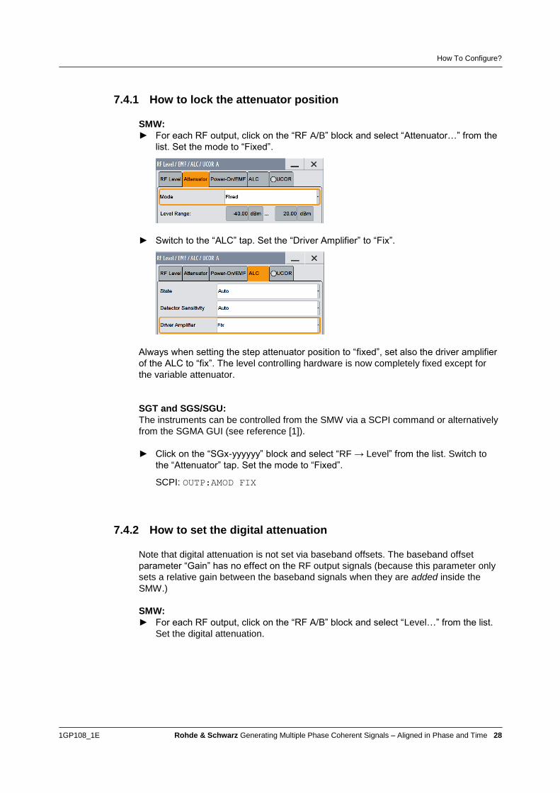
SMW:
► For each RF output, click on the “RF A/B” block and select “Attenuator…” from the
list. Set the mode to “Fixed”.
► Switch to the “ALC” tap. Set the “Driver Amplifier” to “Fix”.
Always when setting the step attenuator position to “fixed”, set also the driver amplifier
of the ALC to “fix”. The level controlling hardware is now completely fixed except for
the variable attenuator.
SGT and SGS/SGU:
The instruments can be controlled from the SMW via a SCPI command or alternatively
from the SGMA GUI (see reference [1]).
► Click on the “SGx-yyyyyy” block and select “RF → Level” from the list. Switch to
the “Attenuator” tap. Set the mode to “Fixed”.
SCPI: OUTP:AMOD FIX
7.4.2 How to set the digital attenuation
Note that digital attenuation is not set via baseband offsets. The baseband offset
parameter “Gain” has no effect on the RF output signals (because this parameter only
sets a relative gain between the baseband signals when they are added inside the
SMW.)
SMW:
► For each RF output, click on the “RF A/B” block and select “Level…” from the list.
Set the digital attenuation.

How To Configure?
1GP108_1E Rohde & Schwarz Generating Multiple Phase Coherent Signals – Aligned in Phase and Time 29
SGT:
The instrument can be controlled from the SMW via a SCPI command or alternatively
from the SGMA GUI (see reference [1]).
► Click on the “SGT-yyyyyy” block and select “RF → Level” from the list. Set the
digital attenuation.
SCPI: SOUR:POW:ATT:DIG 4
SGS/SGU:
The instruments do not support digital attenuation directly because they have no
baseband. Therefore attenuation has to be applied to the external I/Q signal. This
means the attenuation must be done on the instrument providing the I/Q signal.
► On the SMW, decrease the level of the analog I/Q output signal. This can be done
in the following way:
► Click on the “I/Q Analog A/B” block and select “I/Q Analog Outputs…” from the list.
► Change the “Mode” parameter from “Fixed” to “Variable”.
► Set the output level. The output level is a voltage level and adjustable by the
parameter “I/Q Level Vp (EMF)”. EMF stands for electromotive force.
Example:
1.0 V (EMF) measured with an oscilloscope:
At high impedance termination the scope shows a peak voltage of 1.0 V.
At 50 Ω impedance termination the scope shows a peak voltage of 0.5 V.
► Helpful: change the unit of the output level to “dBm”. The default value of 1.0 V
(EMF) converts to 13.01 dBm. This is the full scale level. Now, the attenuation can
be set more easily.
Example:
The attenuation shall be 4.5 dB.
13.01 dBm – 4.5 dB = 8.51 dBm → set “I/Q Level Vp (EMF)” to 8.51 dBm

Calibration – Phase and Time Alignment
1GP108_1E Rohde & Schwarz Generating Multiple Phase Coherent Signals – Aligned in Phase and Time 30
8 Calibration – Phase and Time Alignment To prepare for the actual measurement the setup must be calibrated first, i.e. the
relative phases between the RF channels need to be adjusted and any time delays
between the channels need to be compensated.
The calibration procedure depends on the type of the wanted test signal:
CW signals
Non-CW signals, i.e. I/Q modulated RF signals
Overview – phase and time alignment
Wanted test
signal
Phase alignment Time alignment
Recommended
calibration signal
Details
CW needed Not needed CW See section 9.4
I/Q modulated needed needed FM chirp See section 9.5
Phase alignment is required in every case. Time alignment is required for I/Q
modulated test signals only. Most applications will however make use of I/Q modulated
test signals.
Side note:
Strictly speaking, phase coherence is only defined for CW carriers with equal
frequencies (or for CW carriers whose frequencies are multiples of each other). In case
of I/Q modulated signals1, phase coherence is only defined for the center carriers of
the signals.
8.1 Phase alignment
With LO coupling, the relative phases between the RF carriers are stable, i.e. the RF
carriers are phase coherent. However, the relative phases are unknown at the
beginning – they have arbitrary values. This section explains how to adjust the relative
phases to a specific, wanted value, for example 0°.
1 Due to LO coupling, even CW signals need to be generated via the baseband using I/Q modulation in
order to be able to control the phase. In this and the following sections, however, an I/Q modulated signal
shall denote a modulated baseband signal in the normal sense, i.e. a signal exhibiting a signal bandwidth
such as a LTE signal or a pulsed signal.

Calibration – Phase and Time Alignment
1GP108_1E Rohde & Schwarz Generating Multiple Phase Coherent Signals – Aligned in Phase and Time 31
signal start
CW signals perfect
sync.
t
t
t
t
signal start
t
no
sync.modulated signals
1
2
3
phase
phase
phase
phase
phase
phase
phase
phase
Adjust phase
between channels
► Perform the calibration with the cables that are used to connect to the DUT later
on.
It is important to “include” the cables in the calibration because cables (their type and
length) strongly impact the phase. For example, 1 mm of additional cable length leads
to a phase shift of about 7° at an RF frequency of 6 GHz.
8.2 Time alignment
In applications with I/Q modulated signals, precise synchronization of the baseband
sources is absolutely essential. In contrast, in applications with CW signals it does not
matter whether the signals start perfectly synchronous or not due to the periodicity of
CW signals. Phase alignment alone is sufficient in this case. For I/Q modulated signals
however a synchronous start is crucial, because otherwise the signals will be
misaligned in time as shown in the following figure. Additional time alignment is
required.

Calibration – Phase and Time Alignment
1GP108_1E Rohde & Schwarz Generating Multiple Phase Coherent Signals – Aligned in Phase and Time 32
8.2.1 Prerequisite: baseband synchronization
Synchronized start of all baseband sources is a strict requirement.
Single instrument
If all baseband signals are generated within a single instrument, baseband
synchronization is greatly simplified. The SMW can generate up to eight baseband
signals simultaneously. In all “Advanced” system configurations, the baseband signals
start synchronous as indicated by the “chain” symbol in the “TCM” icon.
In the standard system configuration and in the 2x1x2 “Advanced” system
configuration, the baseband signals need to be synchronized (by the user) by
triggering baseband B internally from baseband A.
Perfect synchronization of the basebands is only assured if all baseband signals have
the same sample rate. It is therefore required to use a common sample rate for all
channels. The sample rate may be changed to different values – this will not change
the internal delays as long as the sample rate is always common for all baseband
signals.
Multiple instruments
If the baseband signals are generated by multiple instruments, baseband
synchronization must be assured. Ideally, the baseband sources share the same
baseband clock. If the baseband clock is not shared among the instruments but each
instrument is running with its own baseband clock, there is a trigger uncertainty of one
clock cycle.
Signal
generator
Signal
generator
Trigger
Trigger delay (cable + precessing time):
e.g. 25 ns
Trigger Uncertainty:
1 clock cycle, e.g. 5 ns
Signal
generator
Signal
generator
Trigger
Trigger delay (cable + precessing time):
e.g. 25 ns
Trigger Uncertainty:
0 clock cycle, 0 ns
Baseband clock
A common baseband clock eliminates the trigger uncertainty.
However, a constant trigger delay remains. It is caused by
the signal propagation delay which depends on the cable type (dielectric
medium) and length
the processing delay of the signal generator, i.e. the time the generator needs
to react to the incoming trigger.

Calibration – Phase and Time Alignment
1GP108_1E Rohde & Schwarz Generating Multiple Phase Coherent Signals – Aligned in Phase and Time 33
The trigger delay is a constant value which can be compensated. In addition to the
trigger delay, there is a signal propagation delay inside the instrument (e.g. caused by
the step attenuator). The resulting total delay needs to be compensated as explained
in detail in section 8.2.2.
Setups that share the baseband clock and trigger are referred to as master-slave
setups. See reference [5] for detailed information. The following figure shows three
SMBVs as an example. Each SMBV generates a single baseband signal. To
synchronize all baseband sources, the master instrument provides its baseband clock
signal to the slave instruments. In addition, the master issues a trigger signal which is
modulated onto the clock signal.
RF 1
RF 2
Sync master
Sync slave
RF 3
Sync slave
CLK OUT
CLK IN
CLK IN
10 MHz
10 MHz
REF OUT
REF OUT
REF IN
REF IN
LO
LO OUT
LO IN
LO
LO OUT
LO IN
phase
coherent
RF signalsCLK OUT
Baseband Clock
+ Trigger
The master-slave setup is supported by the following signal generators:
SGT
SMBV
It is planned that the SMW will support the master-slave mode (or an equivalent) in the
future.
Please see reference [5] on how to configure the instruments for master-slave
operation.
8.2.2 Time alignment principle
Without time alignment the RF signals will not arrive perfectly synchronous at the DUT
due to the following factors:
1) Trigger delays in setups with multiple baseband sources. This issue can be
avoided if all baseband signals are generated by a single SMW.
2) Signal propagation delays inside the instruments. For example caused by
different hardware architectures in different instruments or different step
attenuator positions.

Calibration – Phase and Time Alignment
1GP108_1E Rohde & Schwarz Generating Multiple Phase Coherent Signals – Aligned in Phase and Time 34
3) Signal propagation delays due to cables. For example, there are cables
between the SMW and external instruments such as SGS and SGT. In
addition, there are always cables from the RF outputs to the DUT.
Example setup: One SMW with two sets of SGS/SGU
RF A
Time Reference Plane
RF B
RF C
RF D
In this example, there are no cascaded baseband sources but all baseband signals are
generated by the SMW. Baseband synchronization is therefore assured (factor 1 is
irrelevant) but signal propagation delays still need to be compensated. Factors 2 and 3
cause some delays t between the individual RF signals at the DUT (time reference
plane). By measuring these delays and deliberately delaying the leading signals, the
I/Q modulated RF signals can be aligned in time.
Calibration – How To Do
1GP108_1E Rohde & Schwarz Generating Multiple Phase Coherent Signals – Aligned in Phase and Time 35
9 Calibration – How To Do
9.1 General procedure
The calibration can be done manually or remotely via SCPI commands. Remote
operation is in most applications beneficial because automation saves time, especially
when the calibration needs to be repeated often.
The general calibration procedure is as follows:
► Let the instruments warm up (signal generators, spectrum and network analyzers).
The warm-up time is 30 minutes absolute minimum. Longer warm-up times are
recommended (e.g. several hours for network analyzers).
► Use the cables that are intended to be connected to the DUT. It is essential to
“include” the cables in the calibration.
► Generate calibration signals via the baseband. (See section 9.2.)
► Set the same RF frequency that is intended to be used in the application on all
signal generators. (See section 6.5.)
► Set the RF level on all signal generators. The required RF level depends on the
crest factor of the wanted signal intended to be used in the application. If this crest
factor differs from zero, a correspondingly higher RF level needs to be used for the
calibration. (See section 9.3 and note section 6.6.)
► Adjust the baseband phase offset such that the measured relative phase has the
desired value, e.g. 0°. (See section 7.2.)
► Adjust the parameter “I/Q Delay” such that the measured relative delay between
the RF signals is zero at the DUT. (See section 7.3.) (This step is not required for
CW signals.)
9.2 How to generate the calibration signals
The type of wanted test signal determines the needed calibration signal:
RF signal is a CW signal → recommended calibration signal is a CW signal
(see section 9.4)
RF signal is an I/Q modulated signal → recommended calibration signal is a
FM chirp signal (see section 9.5)
9.2.1 How to generate a CW signal via the baseband
Because of LO coupling, CW signals must be generated via the baseband in order to
be able to set the phase individually for each RF carrier. These (pseudo) CW signals
can be generated by using DC signals for I and Q.

Calibration – How To Do
1GP108_1E Rohde & Schwarz Generating Multiple Phase Coherent Signals – Aligned in Phase and Time 36
There are several ways to do this:
► Use custom digital modulation feature with BPSK modulation and data source “All
1” or “All 0”.
► Use multicarrier CW (MCCW) feature with one carrier only.
► Use the ARB generator with a DC waveform. The waveform can be generated
easily via the ARB menu in the following way: “Create Test Signal” with
“Const I/Q”; set “I Value” to 1 and “Q Value” to 0; press “Generate Signal RAM”
9.2.2 How to generate a FM chirp signal
The FM chirp signal can be generated in just a few steps using the ARB Toolbox Plus
software [4]. The resulting waveform file is provided with this application note. It can be
played back via the ARB generator of the instrument.
Steps required in the ARB Toolbox Plus:
► Select “File” → “Create” from the menu list.
► Select “FM Sweep” and “Linear” as waveform type.
► Set maximum ARB clock rate limit to 200 MHz (i.e. maximum sample rate
supported by SMW).
► Select the following FM sweep settings: 25 MHz deviation, 1 ms sweep time, 0°
start phase, 360° stop phase.
► Select “Auto Scaling”.
► Select output file and press “Run” button.
9.3 How to determine the RF level to be used for
calibration
The calibration signals described in section 9.2 have a crest factor of 0 dB.
In general, the crest factor of a signal is the level difference in units of dB between the
peak envelope power (PEP) level and the average level of a signal. With this definition
a CW signal has a crest factor of 0 dB. Also a pure chirp signal has a crest factor of
0 dB. Mobile communications signals such as LTE signals exhibit high crest factors of
around 10 dB.

Calibration – How To Do
1GP108_1E Rohde & Schwarz Generating Multiple Phase Coherent Signals – Aligned in Phase and Time 37
The SMW displays the PEP and the average levels of the signal:
CW signal: LTE signal:
The user sets the wanted average level of the signal. The SMW’s internal level control
needs to consider not only the user-set average level but also the PEP level to not clip
or deteriorate the signal. The PEP level is therefore the “reference” for levelling inside
the SMW, e.g. for setting the step attenuator and the variable attenuator.
This needs to be taken into account when selecting the RF level for the calibration.
One needs to distinguish between two cases:
1) The wanted signal (intended to be used in the application) has the identical
crest factor as the calibration signal, i.e. 0 dB.
In this case, no extra care needs to be taken. The calibration can be performed
at the same RF level as is used in the application later on.
For example, pulse signals will usually have a crest factor of 0 dB because it is
usually desired to take the highest pulse top power as reference.2
2) The wanted signal (intended to be used in the application) does not have the
identical crest factor as the calibration signal, i.e. different from 0 dB.
In this case, the calibration needs to be performed at the same PEP level as is
used in the application later on.
For example, the wanted signal has a crest factor of 4 dB and its average level
shall be 2 dBm, then the PEP level is 2 dBm + 4 dB = 6 dBm. The calibration
needs to be performed at an RF level of 6 dBm.
The crest factor of the wanted signal can easily be checked e.g. by looking at the level
display on the SMW GUI (as shown above) and subtracting the average level from the
PEP level.
Note that applying digital attenuation does not influence the PEP level and therefore
does not influence the step attenuator and the variable attenuator. It is therefore not
necessary to consider any applied digital attenuation (see section 7.4.2) in above
calculation of the PEP level.
9.4 Phase alignment for CW signals
This section explains how to calibrate the relative phases of the RF signals. The
information is valid for all setups that generate only CW signals.
Note: Readers intending to use I/Q modulated test signals can refer to section 9.5 and
skip this section.
The calibration signal is identical to the wanted test signal, i.e. a CW signal.
2 Pulse signals may have very long pulse-off times which lead to a very low average power of the signal.
Therefore pulse signals usually define the pulse top power of the highest pulse as reference for setting the RF level on a signal generator. In this case, the PEP level and the average level on the SMW equal, the resulting crest factor is 0 dB.

Calibration – How To Do
1GP108_1E Rohde & Schwarz Generating Multiple Phase Coherent Signals – Aligned in Phase and Time 38
There are different methods for measuring the relative phase of CW signals:
Using a vector network analyzer
Using a spectrum analyzer
Using an oscilloscope
9.4.1 Using a vector network analyzer
Performing the phase alignment with a vector network analyzer, e.g. the ZVA, is
convenient for the user and precise in measurement. It is therefore the recommended
method.
► Use one RF signal as the reference channel (at port 1).
► Measure all other RF signals (at ports 2, 3, …) in reference to port 1 to determine
the relative phases.
Since only relative phases are to be measured, a calibration of the ZVA can be
omitted.
► Use CW mode (because measurement is done at one frequency only): SWEEP
key → Sweep Type CW
► Disable the internal sources (they are not to be used): MODE key → Port Config
o Displayed Columns → enable column “Source – RF OFF”
o Turn off all RF Sources in the table by ticking all the RF OFF fields in
the Source Column
(As a result, only the blue triangle LEDs are lightening at the different ZVA ports.)
► Configure the traces. (In this example, four traces are configured.) Do the following
steps for all traces:
o Select trace or create a new trace: TRACE SELECT key → Add Trace
o Switch to a “Phase” measurement: FORMAT key → Phase
Set up a relative phase measurement: MEAS key → Ratios → More
Ratios:
Trace 1: b1/b1
(0°, this trace is only for cross-check purposes)
Trace 2: b2/b1
(relative phase between RF signals at port 2 and port 1)
Trace 3: b3/b1
(relative phase between RF signals at port 3 and port 1)
Trace 4: b4/b1
(relative phase between RF signals at port 4 and port 1)
The following screenshot shows the resulting ZVA display.

Calibration – How To Do
1GP108_1E Rohde & Schwarz Generating Multiple Phase Coherent Signals – Aligned in Phase and Time 39
Pros:
Fast and easy-to-use measurement method
Precise results; a network analyzer is the instrument to measure phase. Even
absolute phases could be measured with this instrument.
Multiple RF signals can be calibrated at a time. With a 4-port ZVA up to 8 RF
signals, e.g. up to 7 relative phases can be measured simultaneously by
making use of the MEAS receivers and the REF receivers (see section 9.5.1
for details.)
Cons:
Network analyzers are generally not standard test equipment available in
every lab, high-end instruments are expensive
9.4.2 Using a spectrum analyzer
The phase alignment can also be performed with a spectrum analyzer and an RF
combiner. This calibration method is based on the fact that two CW signal of identical
RF frequency and level cancel each other completely if they have a phase difference of
180°. In this case, they interfere destructively when added by means of an RF
combiner. A minimum level at the combiner output thus indicates a relative phase of
180°.

Calibration – How To Do
1GP108_1E Rohde & Schwarz Generating Multiple Phase Coherent Signals – Aligned in Phase and Time 40
RF
combiner
Spectrum
analyzer
RF signal 1
RF signal 2
This method of calibration is described in detail in the application note “Phase
Adjustment of Two MIMO Signal Sources with Option B90” (1GP67) [3].
Pros:
Spectrum analyzers are widely-used in labs, even mid-range and high-end
instruments are often available
Suited for RF levels below -80 dBm (depending on spectrum analyzer
sensitivity)
Cons:
Only one relative phase can be calibrated at a time. For more RF carriers
sequential testing is needed.
All RF carriers need to have the same level (level calibration required). After
calibration, the carrier levels may only be changed by means of digital
attenuation to achieve different carrier levels.
9.4.3 Using an oscilloscope
Performing the phase alignment with an oscilloscope is simple but limited in several
aspects (see cons below).
► Connect the RF signals to the oscilloscope input ports (ch1, ch2, ... ).
► Display the sine curves versus time and adjust the horizontal scale.
► Optionally, add a math trace showing for example the difference of two signals
(e.g. ch1-ch2).
► Adjust the vertical scale of each channel such that the sine waves have equal
amplitude on the oscilloscope display.
► Adjust the phase offset on the SMW to align the sine curves. The relative phase is
now 0° (plus measurement uncertainty).

Calibration – How To Do
1GP108_1E Rohde & Schwarz Generating Multiple Phase Coherent Signals – Aligned in Phase and Time 41
Pros:
Oscilloscopes are very common in labs, even mid-range and high-end
instruments are often available
Simple setup
Cons:
Limited phase resolution. Typically, the phase can be adjusted with a
resolution of about 1°.
Not suited for high RF frequencies (depending on oscilloscope class and
specification)
Not suited for low RF levels (e.g. below -30 dBm)
9.5 Phase and time alignment for I/Q modulated signals
This section explains how to calibrate the relative phases of the RF signals and how to
compensate delays between the RF signals. The information is valid for all setups.
Note: Readers intending to use only CW test signals can refer to section 9.4 and skip
this section.
The recommended method for measuring the relative phase and delay of the individual
RF channels makes use of a vector network analyzer (VNA).
Calibration signal:
The calibration signal is a FM chirp signal provided with this application note.
FM chirp settings:
25 MHz deviation → sweep frequency span fspan is 50 MHz
1 ms sweep time, not pulsed → sweep repetition frequency frep is 1 kHz
Please note that fspan of the calibration signal does not need to be equal to the signal
bandwidth of the wanted signal used later in the application. That means, a fspan of
50 MHz can be used for the calibration (using an ZVA), irrespective of the later signal
bandwidth (which can be smaller or larger).

Calibration – How To Do
1GP108_1E Rohde & Schwarz Generating Multiple Phase Coherent Signals – Aligned in Phase and Time 42
9.5.1 Basic information about the VNA
9.5.1.1 Block diagram of a VNA
A VNA cannot only be used to measure S-parameters but also as a multiple receiver system. There are two receivers for each test port, a measurement and a reference receiver that share a common local oscillator.
PORT 1
ZVA
meas receiver b1
ref receiver a1
meas receiver b2
ref receiver a2
PORT 2
LOdirect
receiver
access
Block diagram of a VNA with direct receiver access (2-port R&S®ZVA, source hoop is not shown)
Two signals applied to port 1 and port 2 can be detected by the measurement receivers b1 and b2 and the complex ratio is analyzed according to magnitude and phase. The VNA of the ZVA family offer as option the so-called direct receiver access (Option R&S
®ZVA-B16). The direct receiver leads the measurement and reference
signal from the directional coupler via loops to the front panel and back to the receivers. These loops can be removed to access all the receivers of the VNA. Thus a two port VNA can use its 4 receivers to analyze 4 signals. A four-port ZVA hence offers 8 receivers to analyze 8 signals. A 6-port ZVT20 or 8-port ZVT8 have similar functionalities as ZVA and offer 12 resp. 16 receivers to analyze 12 resp. 16 signals.

Calibration – How To Do
1GP108_1E Rohde & Schwarz Generating Multiple Phase Coherent Signals – Aligned in Phase and Time 43
PORT 1
PORT 4
PORT 2
PORT 3
meas receiver b4
ref receiver a4
meas receiver b3
ref receiver a3
meas receiver b2
ref receiver a2
meas receiver b1
ref receiver a1
LO
Block diagram of a 4-port R&S®ZVA with open direct access loops and without source hoops
9.5.1.2 Measuring the relative phase between two signals
PORT 1
ZVA
meas receiver b1
ref receiver a1
meas receiver b2
ref receiver a1
PORT 2
LO
signal 2
signal 1
Phase measurement between two signals
Both signals are connected to the direct receiver inputs of ZVA. Measuring the ratio of b2 / b1 displays the relationship between both carriers according to magnitude and phase. It is recommended to connect the reference frequencies between the signal source and the VNA. Otherwise the IF bandwidth has to be chosen as wide as the

Calibration – How To Do
1GP108_1E Rohde & Schwarz Generating Multiple Phase Coherent Signals – Aligned in Phase and Time 44
uncertainty of the frequencies. It does not matter if the frequencies slightly vary during the measurement. They only have to remain within the receiver window defined by its measurement bandwidth of the ZVA. If the trace noise is too high apply smoothing or averaging or both. The reduction of the IF bandwidth might fail if the frequency of the DUT is not accurate enough and when no common reference is used.
9.5.2 Calibration of the VNA
A calibration of the VNA is required as a prerequisite for the phase and time alignment. The VNA calibration has to be performed only once at the beginning of the measurement and holds until an instrument preset is performed. A well matched symmetrical power splitter is recommended as calibration standard e.g. the power splitter ZFRSC-183 from Minicircuits that has negligible imbalance for magnitude and phase.
Phase and amplitude imbalance of power splitter ZFRSC-183 from Minicircuits
For higher accuracy requirements, the imbalance of the power splitter can be measured with the network analyzer and used for further correction. For the following application the phase imbalance can be neglected. An additional error is caused by the finite port match of the DUT, the VNA and the power splitter used for calibration. To reduce this error the test port match can be improved by adding well matched attenuators (e.g. BW-S10W2 from Minicircuits) at the end of the cables. Assuming a port match of 25 dB at the end of the test cables resp. the attenuators and a port match of 15 dB of the DUT will result in an a phase error below 0,6°.

Calibration – How To Do
1GP108_1E Rohde & Schwarz Generating Multiple Phase Coherent Signals – Aligned in Phase and Time 45
PORT 1
ZVA
meas receiver b1
ref receiver a1
meas receiver b2
ref receiver a2
PORT 2
LO
signal 2
signal 1
Improvement of test port match with attenuators
Setup: For calibration the power splitter is connected to the source of the VNA and both other ports are connected to the receiver inputs of the VNA.
PORT 1
PORT 4
PORT 2
PORT 3
meas receiver b4
ref receiver a4
meas receiver b3
ref receiver a3
meas receiver b2
ref receiver a2
meas receiver b1
ref receiver a1
LO
Setup for calibration of the VNA with a power splitter

Calibration – How To Do
1GP108_1E Rohde & Schwarz Generating Multiple Phase Coherent Signals – Aligned in Phase and Time 46
Using trace mathematics (Data/Mem), the imbalance of the test setup is corrected (see 9.4.4.2). The influence of the cables and the attenuators is removed as well. These cables with the attenuators at their ends remain connected to the network analyzer (measurement and calibration plane) and will be used to measure the relative phase between the RF signals. Because the amplitude imbalance of the power splitter is negligible (<0.2 dB), the deviation of the magnitudes of both signals is measured with high accuracy as well. This setup can be used for CW measurement and frequency swept measurements.
ZVA 24 VECTOR NETWORK ANALYZER 10 MHz … 24
GHzROHDE& SCHWARZ
SOUTRCE REF MEAS PORT SOUTRCE REF MEAS PORTSOUTRCE REF MEAS PORTSOUTRCE REF MEAS PORT
OUT
IN IN
OUTOUT
IN IN
OUT OUT
IN IN
OUT OUT
IN IN
OUT
2413GND
a1 a4 b4 b2a2b1b3a3
Setup for calibration of the VNA with a power splitter
The VNA calibration needs to be repeated when the measurement points are changed. Trace mathematics are related to the measurement points of the used memory trace. Therefore, the memory trace used for calibration has to have the same measurement point grid.
9.5.3 Measuring the phase between two chirp signals
The measurement is done with chirped signals. To analyze the phase between chirped signals, the receivers of the network analyzer have to sweep across the desired frequency span. To perform the measurements the sweep repetition frequency frep and the frequency span fspan of the chirp have to be known. fspan is the frequency range from the start frequency f1 to the stop frequency fn of the chirp. frep equals 1/ repetition time.
FM Chirp Pulse 1
f f
FM Chirp Pulse
1 n
repetition time
Example of a FM Chirp Pulse.

Calibration – How To Do
1GP108_1E Rohde & Schwarz Generating Multiple Phase Coherent Signals – Aligned in Phase and Time 47
The sampling time of the network analyzer’s receivers has to be at least as long as the period of the chirp pulse to ensure that the receivers can detect the signal at the specific frequency. Therefore an IF filter with a sampling time that is equal or longer than the pulse width of the chirp signal, has to be selected. As a rule of thumb the sampling time is about 1/IFBw (IFBw is the measurement bandwitdth). It is recommended to use a measurement bandwidth of the ZVA of frep/10. For each Chirp Pulse only one frequency point can be measured.
FM Chirp Pulse 1
f f
FM Chirp Pulse
1 2
sampling time
Data sampling of chirp pulse, here it can be seen that in the first Chirp Pulse f1 is measured and in the second Chirp Pulse f2. This is continued until all frequencies are covered.
The setup to measure the relative phase of two chirp signals is shown here:
ZVA 24 VECTOR NETWORK ANALYZER 10 MHz … 24
GHzROHDE& SCHWARZ
SOUTRCE REF MEAS PORT SOUTRCE REF MEAS PORTSOUTRCE REF MEAS PORTSOUTRCE REF MEAS PORT
OUT
IN IN
OUTOUT
IN IN
OUT OUT
IN IN
OUT OUT
IN IN
OUT
2413GND
b4 a2
measurement
and calibration
plane
reference
Setup to measure the phase deviation between two chirp signals

Calibration – How To Do
1GP108_1E Rohde & Schwarz Generating Multiple Phase Coherent Signals – Aligned in Phase and Time 48
The ratio between the used receivers, e.g. b4/a2 shows the relation according to magnitude and phase between the two RF signals. Typically the RF signals have a constant phase offset (due to different start phases) and a phase deviation that increases or decreases linear with frequency (caused by different lengths or delay times of the signal paths inside and/or outside the signal generators). The relation between phase and frequency for non-dispersive paths (like coaxial cables as used in this application) is:
ff 360)(
where is the delay time of the path. For a cable, the delay time is directly related to its
mechanical length Lmech via the permittivity of the dielectric material inside the cable and the velocity of light c.
c
Lmech
(The velocity of light is c 2.9979108 m/s 30 cm/ns 1 ft/ns and can be easily remembered as "one light foot", which is approximately the distance which light travels within 1 ns.) Therefore a difference between the electrical lengths of the signal paths will cause a negative or positive slope of the phase with increasing frequency, as it can be seen in the following figure.
.
Linear phase deviation between two chirp signals before phase and time alignment on the signal generator
Two measurement parameters of the trace statistics function are of special interest in this application: mean value and phase delay.
The mean value shows the difference of the start phases, i.e. the relative phase of the RF signals. This parameter is used to align the relative phases of the signal sources to any desired value, e.g. to 0°.
The phase delay shows the difference in electrical length of the two signal paths. This parameter is used to align the timing of the signal sources.
Example: In above figure, the trace has a slope and crosses the center frequency at roughly -230°. The trace statistics show a mean value of -232.96° and a phase delay of 20.6 ns. By adjusting the phase on the signal generator, the trace can be “shifted” such that the measured relative phase is 0°. That means the mean value is 0° and the crossing is at 0°. In a next step, by adjusting the delay on the signal generator, the slope of the trace can be eliminated. That means the measured phase delay is in the picosecond or femtosecond range and the trace is flat. The following figure shows the result after phase and time alignment.

Calibration – How To Do
1GP108_1E Rohde & Schwarz Generating Multiple Phase Coherent Signals – Aligned in Phase and Time 49
Phase deviation between two chirp signals after phase and time alignment on the signal generator
Using this technique corrects for phase deviations of the signal sources and the external cabling. Therfore, it is not necessary to have expensive cables with identical electrical lengths (so-called phase-matched cables). It is only required to have phase-stable cables. Important for the case that ratios with the same index are used: Ratios with same index e.g. a1/b1 are normally reflection measurements. Therefore the trace statistics function "Phase Delay / EL Length" shows half the phase delay. That means that the measured value for this ratio has to be multiplied by factor of 2 for entering it on the signal generators.
9.5.4 Step-by-step guide for the phase and time alignment
In general, before doing the calibration all instruments need to be warmed up.
9.5.4.1 Step 1 - General VNA settings
Connect the cables from the signal generators to REF a2 and MEAS b4 inputs of ZVA.
Activate the chirp signals at the signal generators. The power level at direct receiver input should be - 20 dBm or lower to avoid receiver compression. Add attenuators if necessary.
Connect the 10 MHz reference frequency signal of the signal generator to the ZVA. Switch ZVA to external reference frequency.
System - External Reference

Calibration – How To Do
1GP108_1E Rohde & Schwarz Generating Multiple Phase Coherent Signals – Aligned in Phase and Time 50
Select the frequency range of the chirp signals. In this example the chirp has a span of 50 MHz (called fspan in this document). The RF frequency is 1 GHz.
Channel - Stimulus Center 1 GHz Span 50 MHz
Select a suitable measurement bandwidth that is 10 / frep, or lower. In this example 100 Hz.
Channel - Pow BW Avg - MEAS BANDWIDTH: 100 Hz
Fine Adjust: Select filters with high selectivity
Select a suitable ratio, in this case b4/a2 (P1) and select Phase format. Src Port 1 means that the generator is driving port 1.
Trace - Meas - Ratios - More Ratios - b4/a2 Source Port: Port 1
Trace - Format - Unwrapped Phase

Calibration – How To Do
1GP108_1E Rohde & Schwarz Generating Multiple Phase Coherent Signals – Aligned in Phase and Time 51
Add as many traces and ratios e.g. b3/a2, b1/a2 as necessary. Select Port 1 as source port for every ratio. Because all phases are measured in this example in respect of a2, a2 is used as reference. Therefore use a2 as denominator for each ratio.
Trace - Meas - Ratios - More Ratios Source Port: Port 1
Trace - Format - Unwrapped Phase
9.5.4.2 Step 2 - Calibration of the VNA
Please see section 9.5.2 for general information on VNA calibration.
Connect the power splitter to port 1 of the ZVA. Connect the test port cables with the attenuators from the receivers (e.g. a2 and b4) directly to the power splitter.
Activate trace 1 (b4/a2) e.g. by clicking into the diagram of trace 1 and apply trace math
Trace - Trace Funct - Data->Mem MATH=DATA/MEM SHOW MEM : Off
Apply the calibration to all other ratios. The a2 receiver is used in this example as reference, so remains always connected to the power splitter during calibration. To apply the calibration to another ratio, e.g. b3/a2 connect the power splitter at REF a2 and MEAS b3. Activate trace 2 (b3/a2) e.g. by clicking into the diagram of trace 2 and apply trace math All traces show 0° as result
Trace - Trace Funct - Data->Mem MATH=DATA/MEM SHOW MEM : Off

Calibration – How To Do
1GP108_1E Rohde & Schwarz Generating Multiple Phase Coherent Signals – Aligned in Phase and Time 52
9.5.4.3 Step 3 – Measuring the phase between the chirp signals
Please see section 9.5.3 for background information.
Apply the signals to all the receivers
Activate the first ratio, e.g. b4/a2 by clicking on the trace line with the mouse.
Phase alignment: Activate trace statistics to measure the mean value of the phase. The mean value shows the constant phase offset between the two signals. Read out this value to set a defined relative phase on the SMW, e.g. to adjust the relative phase to 0°. In case there is a spike appearing at the center frequency, this spike can be eliminated using the impairments feature of the SMW. By setting I and Q offsets the observed carrier leakage can be removed to not influence the mean value.
Trace - Trace Funct - Trace Statistics - Mean / Std Dev
Time alignment: Activate trace statistics to measure the phase delay and electrical length. The phase delay (Phs Dly) is displayed. Read out this value to cancel time delays on the SMW.
Trace - Trace Funct - Trace Statistics - Phase Delay / El Length
After the alignment, the measured phase on the VNA is constant over the entire frequency range (due to time alignment) and adjusted to 0° (due to phase alignment) as can be seen in the following figure.

Calibration – How To Do
1GP108_1E Rohde & Schwarz Generating Multiple Phase Coherent Signals – Aligned in Phase and Time 53
Final result of phase and time alignment
In this example, the time alignment is excellent with a residual phase delay of less than
1 ps.
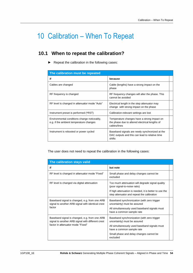
Calibration – When To Repeat
1GP108_1E Rohde & Schwarz Generating Multiple Phase Coherent Signals – Aligned in Phase and Time 54
10 Calibration – When To Repeat
10.1 When to repeat the calibration?
► Repeat the calibration in the following cases:
The calibration must be repeated
if because
Cables are changed Cable (lengths) have a strong impact on the
phase
RF frequency is changed RF frequency changes will alter the phase. This
cannot be avoided
RF level is changed in attenuator mode “Auto” Electrical length in the step attenuator may
change with strong impact on the phase
Instrument preset is performed (*RST) Calibration-relevant settings are lost
Environmental conditions change noticeably,
e.g. if the ambient temperature changes
Temperature changes have a strong impact on
the phase due to altered electrical lengths of
cables/lines
Instrument is rebooted or power cycled Baseband signals are newly synchronized at the
DAC outputs and this can lead to relative time
shifts
The user does not need to repeat the calibration in the following cases:
The calibration stays valid
if but note
RF level is changed in attenuator mode “Fixed” Small phase and delay changes cannot be
excluded
RF level is changed via digital attenuation Too much attenuation will degrade signal quality
(poor signal-to-noise ratio)
If high attenuation is needed, it is better to use the
step attenuator and repeat the calibration
Baseband signal is changed, e.g. from one ARB
signal to another ARB signal with identical crest
factor
Baseband synchronization (with zero trigger
uncertainty) must be assured
All simultaneously used baseband signals must
have a common sample rate
Baseband signal is changed, e.g. from one ARB
signal to another ARB signal with different crest
factor in attenuator mode “Fixed”
Baseband synchronization (with zero trigger
uncertainty) must be assured
All simultaneously used baseband signals must
have a common sample rate
Small phase and delay changes cannot be
excluded

Calibration – When To Repeat
1GP108_1E Rohde & Schwarz Generating Multiple Phase Coherent Signals – Aligned in Phase and Time 55
10.2 Reproducibility
Level
Assuming a user has a scenario where the RF level is alternating. In addition, the RF
level is not set via digital attenuation (due to a large level difference) but via the step
attenuator.
Example:
Level 1 → initial calibration needed (cal 1)
Level 2 → new calibration needed (cal 2)
Level 1 → phase offsets and delays determined during cal 1 can be reused
Level 2 → phase offsets and delays determined during cal 2 can be reused
Reproducibility is given because the step attenuator position is reproducible at level
changes.
Frequency
Assuming a user has a scenario where the RF frequency is alternating.
Example:
Frequency 1 → initial calibration needed (cal 1)
Frequency 2 → new calibration needed (cal 2)
Frequency 1 → phase offsets and delays determined during cal 1 can be reused
Frequency 2 → phase offsets and delays determined during cal 2 can be reused
Reproducibility is given with LO coupling. The phase is reliably reproducible at
frequency changes.
REF coupling
As a remark, when reference frequency coupling is used reproducibility is not assured.
In contrast to LO coupling where only a single synthesizer is used, multiple
synthesizers are involved when reference coupling is applied. Due to the synthesizer
design (filters, VCO etc.) the phase is not reliably reproducible at frequency and level
changes.

Measurement Results for Phase Stability
1GP108_1E Rohde & Schwarz Generating Multiple Phase Coherent Signals – Aligned in Phase and Time 56
11 Measurement Results for Phase Stability This section presents some measurement results to demonstrate the stability of the
relative phase over time.
The phase measurements were obtained using a ZVA. The ZVA was configured as
described in section 9.4.1. All measurements were performed with CW signals as RF
test signals. The ZVA used the 10 MHz reference signal from a generator (e.g. from
SMW).
In addition to the relative phases, also the temperature was captured (read out from
instrument) to be able to correlate phase fluctuations with temperature changes.
The results shown in this application note are just some example measurements out of
a more comprehensive test series. For anyone interested, more measurements can be
requested via the Rohde & Schwarz support centers (see last page).
The environmental conditions of the test series was not worst case but intentionally
also not ideal. The setup was placed on a normal lab bench. The room was not
specifically temperature controlled. However care was taken that temperature stayed
nearly constant. The tests were performed at room temperature (which is not the ideal
condition for external cabling but most practical for the users). Vibrations and other
disturbance were avoided.
11.1 Pretest
The following pretest was performed to get a feeling for the measurement (taking into
account equipment, RF cabling, and environmental conditions) and the range in which
the measurement provides meaningful data.
The SMW generated a single CW test signal that was split apart and fed to two ports of
the ZVA. The relative phase between port 1 and port 2 was measured.
SMW ZVA
RF10 dB coupler 1
2
At an RF frequency of 20 GHz, the measurement variation was found to be
< 0.3° within 1 hour at almost constant temperature
< 0.45° within 11 hours and 0.5 °C temperature change
At an RF frequency of 40 GHz, the measurement variation increased to < 0.5° within
one hour at constant temperature.

Measurement Results for Phase Stability
1GP108_1E Rohde & Schwarz Generating Multiple Phase Coherent Signals – Aligned in Phase and Time 57
The measurement variation needs to be kept in mind when looking at the
measurement results shown in the following sections. The data are not corrected for
this variation.
11.2 2 GHz run
RF frequency: 2 GHz
Number of channels: 3
LO coupling: yes
Temperature: constant, room temperature
(plot shows internal instrument temperature)
Data shown over: 1 hour
Setup: 3x SGT
SGT
SGT
SGT
RF
RF
RFLO
LO
ARB
ARB
ARB
Measured drift of relative phase:
b2/b1: < 0.2° (SGT / SGT)
b3/b1: < 0.1° (SGT / SGT)
Note that even minor temperature changes (less than 0.1 °C) have an influence on the
relative phases as can be seen in above data (temperature bump at 2500 s).
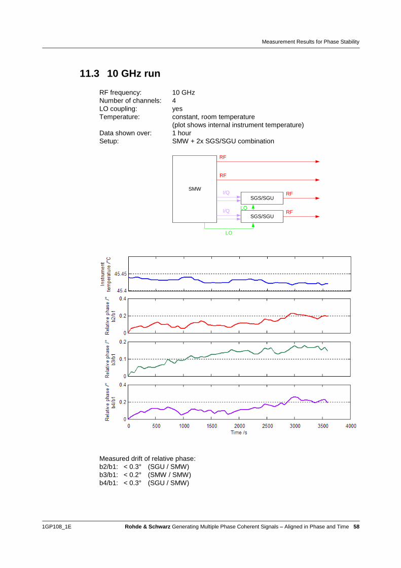
Measurement Results for Phase Stability
1GP108_1E Rohde & Schwarz Generating Multiple Phase Coherent Signals – Aligned in Phase and Time 58
11.3 10 GHz run
RF frequency: 10 GHz
Number of channels: 4
LO coupling: yes
Temperature: constant, room temperature
(plot shows internal instrument temperature)
Data shown over: 1 hour
Setup: SMW + 2x SGS/SGU combination
SMW
SGS/SGU
SGS/SGU
RF
RF
RF
RFLO
LO
I/Q
I/Q
Measured drift of relative phase:
b2/b1: < 0.3° (SGU / SMW)
b3/b1: < 0.2° (SMW / SMW)
b4/b1: < 0.3° (SGU / SMW)

Measurement Results for Phase Stability
1GP108_1E Rohde & Schwarz Generating Multiple Phase Coherent Signals – Aligned in Phase and Time 59
11.4 20 GHz run
RF frequency: 20 GHz
Number of channels: 4
LO coupling: yes
Temperature: constant, room temperature
(plot shows internal instrument temperature)
Data shown over: 1 hour
Setup: SMW + 2x SGS/SGU combination
SMW
SGS/SGU
SGS/SGU
RF
RF
RF
RFLO
LO
I/Q
I/Q
Measured drift of relative phase:
b2/b1: < 0.4° (SGU / SMW)
b3/b1: < 0.6° (SMW / SMW)
b4/b1: < 0.6° (SGU / SMW)
Note that the measurement variation at 20 GHz is < 0.3° within one hour.
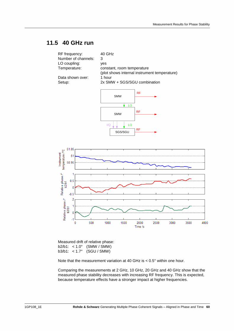
Measurement Results for Phase Stability
1GP108_1E Rohde & Schwarz Generating Multiple Phase Coherent Signals – Aligned in Phase and Time 60
11.5 40 GHz run
RF frequency: 40 GHz
Number of channels: 3
LO coupling: yes
Temperature: constant, room temperature
(plot shows internal instrument temperature)
Data shown over: 1 hour
Setup: 2x SMW + SGS/SGU combination
SGS/SGU
SMW
I/Q
RF
RF
RF
LO
LO
SMW
Measured drift of relative phase:
b2/b1: < 1.0° (SMW / SMW)
b3/b1: < 1.7° (SGU / SMW)
Note that the measurement variation at 40 GHz is < 0.5° within one hour.
Comparing the measurements at 2 GHz, 10 GHz, 20 GHz and 40 GHz show that the
measured phase stability decreases with increasing RF frequency. This is expected,
because temperature effects have a stronger impact at higher frequencies.

Measurement Results for Phase Stability
1GP108_1E Rohde & Schwarz Generating Multiple Phase Coherent Signals – Aligned in Phase and Time 61
11.6 10 hour run
RF frequency: 10 GHz
Number of channels: 4
LO coupling: yes
Temperature: changed by 0.8 °C, room temperature
(plot shows internal instrument temperature)
Data shown over: 10 hours
Setup: SMW + 2x SGS/SGU combination
SMW
SGS/SGU
SGS/SGU
RF
RF
RF
RFLO
LO
I/Q
I/Q
Measured drift of relative phase:
b2/b1: < 2.2° (SGU / SMW)
b3/b1: < 2.4° (SMW / SMW)
b4/b1: < 0.7° (SGU / SMW)

Measurement Results for Phase Stability
1GP108_1E Rohde & Schwarz Generating Multiple Phase Coherent Signals – Aligned in Phase and Time 62
11.7 LO versus 1 GHz REF coupling
RF frequency: 2 GHz
Number of channels: 2
Temperature: changed by 0.4 °C, room temperature
(plot shows internal instrument temperature)
Data shown over: 8 hours
Coupling: LO
Setup: 2x SGT
SGT
SGT
RF
RFLO
ARB
ARB
Coupling: 1 GHz REF
Setup: 2x SGT
SGT
SGT
RF
RF1 GHz
ARB
ARB

Measurement Results for Phase Stability
1GP108_1E Rohde & Schwarz Generating Multiple Phase Coherent Signals – Aligned in Phase and Time 63
Measured drift of relative phase:
LO coupling: < 0.4°
1 GHz REF coupling: < 1.0°
As expected, LO coupling exhibits a better phase stability than 1 GHz reference
coupling. However, the stability achieved by 1 GHz REF coupling may be sufficient for
some applications.

Quick Guide
1GP108_1E Rohde & Schwarz Generating Multiple Phase Coherent Signals – Aligned in Phase and Time 64
12 Quick Guide This section presents some settings and important points at a glance. This compact
summary is not comprehensive.
Setup and settings:
Use LO coupling, i.e. common synthesizer for all signal generators. This
requires option B90 or K90.
Set the phase via the baseband.
Make sure that all baseband sources are synchronized.
Use high-quality, phase stable cables as short in length as possible for all LO
and RF connections.
Set RF frequency to same value on all signal generators (before enabling LO
coupling).
Change RF level digitally via the baseband attenuation to conserve calibrated
relative phase.
Calibration:
Use a network analyzer for phase and time alignment, e.g. the ZVA.
Up to 8 RF signals can be calibrated simultaneously with a four-port ZVA.
Include the RF connection cables in the calibration.
Calibrate at the same PEP level as is used in the application later on.
Adjust phase digitally via the “Phase Offset” parameter.
Compensate delays digitally via the “I/Q Delay” parameter.
Repeat the calibration if RF frequency is changed and if RF level is changed
via step attenuator.
Environment:
Temperature is THE major influence factor on the phase stability and must
therefore be kept constant.
FAQs:
How many instruments can be cascaded with LO coupling?
There is no defined limit. The LO signal level is held constant when the
instruments are daisy-chained. The effective LO cable length increases with
each cascaded instrument and with it the temperature effect. Therefore, it is
always a question of environmental conditions and how much phase drift can
be tolerated. A combination of symmetrical LO branching and additional daisy-
chaining may help to counteract the temperature effects.
What is the specified phase stability?
There is no specified value because the phase stability depends on the system
used (i.e. the used instruments, cable setup, RF frequency and number of
channels) and on the environmental conditions (temperature variations).
Measured data can be seen in section 11.

How to Improve the Phase Stability of a Phase Coherent System
1GP108_1E Rohde & Schwarz Generating Multiple Phase Coherent Signals – Aligned in Phase and Time 65
13 How to Improve the Phase Stability of a Phase Coherent System Phase coherence of two signals will never be absolutely perfect in the real world.
There will be some (small) drift of the relative phase over time.
This section summarizes some hints for improving the phase stability of a multichannel
phase coherent system.
The following factors affect the phase stability:
Signal generator coupling
Temperature
Cabling
Signal generator coupling
As explained in section 3.2, there are several ways to stabilize the relative phase
between two signals/signal generators. Reasonable phase stability is however only
assured for 1 GHz REF coupling and for LO coupling with LO coupling being clearly
superior to 1 GHz REF coupling. The reason is mainly the synthesizer noise. In case of
REF coupling, both synthesizers are in use. The uncorrelated synthesizer noise A and
A’ do affect the phase stability as illustrated in the following simplified block diagram.
The noise contribution B and B’ from the output RF chain is very small compared to the
synthesizer noise A and A’. The relative phase of the two RF outputs is influenced by
all four noise contributions. In case of LO coupling, only one common synthesizer is in
use. The synthesizer noise A does not affect the phase stability, since it is the same on
both RF outputs (correlation). It thus cancels out. The relative phase is influenced only
by the small noise contributions B and B’.

How to Improve the Phase Stability of a Phase Coherent System
1GP108_1E Rohde & Schwarz Generating Multiple Phase Coherent Signals – Aligned in Phase and Time 66
► As a consequence, use LO coupling to achieve best phase stability.
Temperature
As explained in section 6.1, the temperature has a significant influence on the phase
stability. It is therefore required to keep the temperature as constant as possible (T <
0.1 °C is recommended). How to achieve such constant temperature conditions?
Normal room air conditioning is often too unstable, creating interrupted cold air flows.
Also, any other ventilation, e.g. opening windows, doors, even people passing by the
setup, creates unstable air flows. These effects change the temperature – on very
small scales, but sufficient to impact the relative phase noticeably. To overcome this,
one way is to use temperature controlled chambers offered by specialized vendors.
There are many different temperature chambers on the market. It is important to check
the specification sheet for relevant parameters like temperature deviation in time
(should be in the range ±0.1 °C to ±0.5 °C), test space volume (the test system must fit
into the chamber plus 1/3 air volume should remain), and heat compensation (the test
system generates heat that must be absorbed by the chamber). For big test systems
walk-in temperature chambers are available on the market offering still good
specifications for temperature deviation of about ±1 °C. Temperature controlled
chambers have two benefits. Firstly, they keep the temperature constant. Secondly,
the can apply heat. Heating up the whole test system to e.g. 40 °C is beneficial
regarding the temperature dependence of the dielectric medium in the cables, PTFE.
The teflonTM
knee region, happening at room temperature, is avoided and any
temperature fluctuations have less impact on the phase.
► In a nutshell, keep ambient temperature constant (T << 1 °C) to achieve good
phase stability.
► If very high phase stability is required, consider using a temperature controlled
chamber.
Cabling
As explained in section 6.2, the usage of proper, phase-stable cables for all LO and RF
connections is absolutely crucial:
► Use semi-rigid cables for all permanent connections. They are cheaper and less
prone to touching and vibrations than flexible cables.
► Use flexible cables only where absolutely needed.
► Keep all cable lengths as short as possible (especially when working at high RF
frequencies) to minimize the temperature effect on the phase.

Special Applications
1GP108_1E Rohde & Schwarz Generating Multiple Phase Coherent Signals – Aligned in Phase and Time 67
14 Special Applications
14.1 Phase coherence at very low RF frequencies
The phase coherence B90/K90 option has a lower frequency limit of 200 MHz for SMW
and SMBV and 80 MHz for SGT and SGS (see also the instruments’ datasheets).
So the question is: how to achieve phase coherence for multiple RF signals at
frequencies 200 MHz (for SMW) or 80 MHz (for SGT)?
There are different approaches:
1 GHz REF coupling
> 200 MHz RF frequency (SMW) + baseband frequency offset
Direct baseband signal output + baseband frequency offset
It depends on the application which approach is applicable and makes most sense.
1 GHz REF coupling
At low RF frequencies, 1 GHz REF coupling is a good alternative to LO coupling. The
phase stability achievable with 1 GHz REF coupling is very good as can be seen in the
following example measurement at 70 MHz RF frequency (performed with four SGTs).
The table in section 15.1 lists setups that support 1 GHz REF coupling.

Special Applications
1GP108_1E Rohde & Schwarz Generating Multiple Phase Coherent Signals – Aligned in Phase and Time 68
> 200 MHz RF frequency + baseband frequency offset
The RF frequency is set to a value supported by the B90/K90 option, e.g. above
200 MHz for the SMW, say 201 MHz. A negative baseband frequency offset is applied
to achieve the wanted output frequency. For example, the wanted output frequency
shall be 180 MHz, then the RF frequency is set to 201 MHz and a negative frequency
offset of –21 MHz is applied in the baseband. The resulting RF output signal will have
a frequency of 180 MHz in this example.
Depending on the installed hardware and options the instruments offer different
baseband bandwidths. For example a SMW with B10 option can apply negative
frequency offsets of up to 80 MHz, a SMW with B9 option can apply negative
frequency offsets of up to 1000 MHz.
See section 7.2 on how to apply a frequency offset in the baseband.
Direct baseband signal output + baseband frequency offset
When applying a baseband frequency offset the I signal as well as the Q signal
transform into IF signals and can be used directly to supply the DUT (instead of the RF
signal). The instruments have dedicated connectors for I and Q signal output. For
example, the wanted output frequency shall be 70 MHz, then a positive frequency
offset of 70 MHz is applied in the baseband. The RF signal is not used. Instead the I
signal is used directly which has an (RF) frequency of 70 MHz in this example.
Depending on the installed hardware and options the instruments offer different
baseband bandwidths. For example a SMW with B10 option can apply positive
frequency offsets of up to 80 MHz, a SMW with B9 option can apply positive frequency
offsets of up to 1000 MHz.
See section 7.2 on how to apply a frequency offset in the baseband.
14.2 Phase coherence for multichannel setups with
different RF frequencies
Some applications require multiple phase coherent signals but with different RF
frequencies for each signal.
Channel 1
Channel 2
Channel 3
Channel n
f1
f2
f3
fn
RF
RF
RF
RF
Signal
source
So the question is: how to achieve phase coherence for multiple RF signals each with
different frequencies?

Special Applications
1GP108_1E Rohde & Schwarz Generating Multiple Phase Coherent Signals – Aligned in Phase and Time 69
There are different approaches:
1 GHz REF coupling
LO coupling + baseband frequency offset
It depends on the application which approach is applicable and makes most sense.
1 GHz REF coupling
Multiple signal generators, i.e. synthesizers, can be coupled by a common 1 GHz
reference signal. Since different synthesizers are in operation, each of them can be set
to a different RF frequency. See section 3 for details.
The table in section 15.1 lists setups that support 1 GHz REF coupling.
For example, the following setup consisting of multiple SGTs can be used to implement
a multichannel phase coherent system with different output frequencies.
f1
f2
f3
RF
RF
RF
1 GHz REF
1 GHz REF
SYNC
SYNC
1 GHz REF SYNC
The phase stability of such setups depends on the RF frequency and is generally very
good at low frequencies (see sections 11.7 and 14.1).
LO coupling + baseband frequency offset
Multiple signal generators coupled with a common LO signal naturally generate signals
with identical RF frequencies. Different RF frequencies can therefore only be achieved
by applying a frequency offset in the baseband. For example, the wanted output
frequencies shall be 1,56 GHz, 1.60 GHz and 1.64 GHz. The RF frequency is set to
1.60 GHz on all signal generators. The shared LO frequency will therefore be
1.60 GHz. A negative frequency offset of –40 MHz is applied in the baseband of one
signal generator; a positive frequency offset of 40 MHz is applied in the baseband of
another signal generator. The resulting RF output signals will have the desired
frequencies of 1,56 GHz, 1.60 GHz and 1.64 GHz in this example.
Depending on the installed hardware and options the instruments offer different
baseband bandwidths. For example a SMW with B10 option can apply frequency
offsets of up to ±80 MHz, a SMW with B9 option can apply frequency offsets of up to
±1000 MHz.
See section 7.2 on how to apply a frequency offset in the baseband.
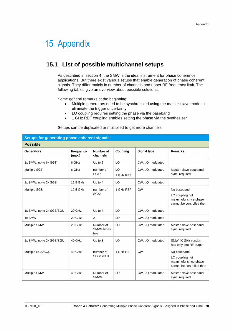
Appendix
1GP108_1E Rohde & Schwarz Generating Multiple Phase Coherent Signals – Aligned in Phase and Time 70
15 Appendix
15.1 List of possible multichannel setups
As described in section 4, the SMW is the ideal instrument for phase coherence
applications. But there exist various setups that enable generation of phase coherent
signals. They differ mainly in number of channels and upper RF frequency limit. The
following tables give an overview about possible solutions.
Some general remarks at the beginning:
Multiple generators need to be synchronized using the master-slave mode to
eliminate the trigger uncertainty.
LO coupling requires setting the phase via the baseband
1 GHz REF coupling enables setting the phase via the synthesizer
Setups can be duplicated or multiplied to get more channels.
Setups for generating phase coherent signals
Possible
Generators Frequency
(max.)
Number of
channels
Coupling Signal type Remarks
1x SMW, up to 6x SGT 6 GHz Up to 8 LO CW, I/Q modulated
Multiple SGT 6 GHz number of
SGTs
LO
1 GHz REF
CW, I/Q modulated Master-slave baseband
sync required
1x SMW, up to 2x SGS 12.5 GHz Up to 4 LO CW, I/Q modulated
Multiple SGS 12.5 GHz number of
SGSs
1 GHz REF CW No baseband;
LO coupling not
meaningful since phase
cannot be controlled then
1x SMW, up to 2x SGS/SGU 20 GHz Up to 4 LO CW, I/Q modulated
1x SMW 20 GHz 2 LO CW, I/Q modulated
Multiple SMW 20 GHz Number of
SMWs times
two
LO CW, I/Q modulated Master-slave baseband
sync required
1x SMW, up to 2x SGS/SGU 40 GHz Up to 3 LO CW, I/Q modulated SMW 40 GHz version
has only one RF output
Multiple SGS/SGU 40 GHz number of
SGS/SGUs
1 GHz REF CW No baseband;
LO coupling not
meaningful since phase
cannot be controlled then
Multiple SMW 40 GHz Number of
SMWs
LO CW, I/Q modulated Master-slave baseband
sync required

Abbreviations
1GP108_1E Rohde & Schwarz Generating Multiple Phase Coherent Signals – Aligned in Phase and Time 71
Setups for generating phase coherent signals
Possible – with external ARB
Generators Frequency
(max.)
Number of
channels
Coupling Signal type Remarks
Multiple ARBs with SGS 12.5 GHz Number of ARB-
SGS pairs
LO
1 GHz REF
CW, I/Q modulated Baseband sync
required
Multiple ARBs with SGS/SGU 40 GHz Number of ARB-
SGS/SGU pairs
LO
1 GHz REF
CW, I/Q modulated Baseband sync
required
The external ARB can be e.g. a wideband ARB such as the R&S®AFQ100B.
Note: LO coupling requires setting the phase in the baseband. For phase alignment the
external ARB should offer a means to control the phase. The R&S®AFQ100B has no
dedicated means to set the phase; I and Q delays can be set in a range of ±2 ns with a
resolution of 10 ps.
16 Abbreviations ALC Automatic level control
ARB Arbitrary waveform generator
CW Continuous wave
DAC Digital to analog converter
DC Direct current
DUT Device under test
I/Q In-phase/quadrature
LO Local oscillator
PLL Phase locked loop
PTFE Polytetrafluoroethylene
REF Reference
RF Radio frequency
S/N Signal to noise ratio
SCPI Standard commands for programmable instruments
Tx Transmit
VCO Voltage controlled oscillator
VSG Vector signal generator
VNA Vector network analyzer
WV ARB waveform

References
1GP108_1E Rohde & Schwarz Generating Multiple Phase Coherent Signals – Aligned in Phase and Time 72
17 References [1] Rohde & Schwarz Application Note, “Connecting and Interfacing with SGMA
Instruments” (1GP103)
[2] “Temperature Stability of Coaxial Cables” by K.Czuba and D. Sikora, ISE,
Warsaw University of Technology, Nowowiejska 15/19, 05-077 Warsaw,
Poland
[3] Rohde & Schwarz Application Note, “Phase Adjustment of Two MIMO Signal
Sources with Option B90” (1GP67)
[4] Rohde & Schwarz Application Note, “R&S ARB Toolbox Plus” (1GP88)
[5] Rohde & Schwarz Application Note, “Time Synchronous Signals with Multiple
R&S®SMBV100A Vector Signal Generators” (1GP84)
[6] Rohde & Schwarz Application Note, “Multi-Channel Signal Generation
Applications with R&S®SMW200A – Overview” (1GP106)
18 Ordering Information Please visit the product websites at www.rohde-schwarz.com for comprehensive ordering information (“Options”) on the following Rohde & Schwarz instruments:
R&S®SMW200A vector signal generator
R&S®SMBV100A vector signal generator
R&S®SGT100A SGMA vector RF source
R&S®SGS100A SGMA RF source
R&S®SGU100A SGMA upconverter
R&S®ZVA vector network analyzer

Rohde & Schwarz
The Rohde & Schwarz electronics group offers
innovative solutions in the following business fields:
test and measurement, broadcast and media, secure
communications, cybersecurity, radiomonitoring and
radiolocation. Founded more than 80 years ago, this
independent company has an extensive sales and
service network and is present in more than 70
countries.
The electronics group is among the world market
leaders in its established business fields. The
company is headquartered in Munich, Germany. It also
has regional headquarters in Singapore and Columbia,
Maryland, USA, to manage its operations in these
regions.
Regional contact
Europe, Africa, Middle East +49 89 4129 12345 [email protected] North America 1 888 TEST RSA (1 888 837 87 72) [email protected] Latin America +1 410 910 79 88 [email protected] Asia Pacific +65 65 13 04 88 [email protected] China +86 800 810 82 28 |+86 400 650 58 96 [email protected] Sustainable product design
ı Environmental compatibility and eco-footprint
ı Energy efficiency and low emissions
ı Longevity and optimized total cost of ownership
This application note and the supplied programs may only be used subject to the conditions of use set forth in the download area of the Rohde & Schwarz website. R&S
® is a registered trademark of Rohde & Schwarz GmbH & Co.
KG; Trade names are trademarks of the owners.
Rohde & Schwarz GmbH & Co. KG
Mühldorfstraße 15 | 81671 Munich, Germany
Phone + 49 89 4129 - 0 | Fax + 49 89 4129 – 13777
www.rohde-schwarz.com