Embed Size (px)
Citation preview

3Specifications are subject to change without notice. For further information, please contact L. S. TECH office.
- - VARISTOR -
Introduction ZOV(Zinc Oxide Varistor) varistors are nonlinear two-electrode semiconductor voltage-dependant resistors, which are designed for transient voltage suppression and surge energy absorption. Transient over-voltages are a major cause for malfunction or total failure of electronic circuitry and equipment. Therefore, varistors can be widely applied in different areas. Our products perform very reliably and experience low failure rates. Most of them are UL, CSA and VDE approved.
Features
Wide Operating voltage range, Vdc form 14V to 1465V Large absorbing transient energy capability Very short response time Low clamping ratio and no follow-on current High resistance insulation material prevents the electric arching to the adjacent devices.
Applications
Transistor, diode, IC, thyristor or triac semiconductor protection
Surge protection in consumer electronics
Surge protection in industrial electronics
Surge protection in communication, measuring and controller electronics
Surge protection in electronic home appliances and gas/petroleum appliances.
Electrostatic discharge and noise spike suppression
Relay and electromagnetic valve surge absorption

4Specifications are subject to change without notice. For further information, please contact L. S. TECH office.
Marking & Part Numbering System Please refer to the following part numbering system when place order.
ZOV
Brand Mark: ZOV is our brand which stands for Zinc Oxide Varistors. This can be any of your designated brand if you’re OEM customer to us.
Element Diameter: Which can be 05 / 07 / 10 / 14 / 20 / 25 / 32 / 34 / 40 / 53 (mm). These two digits stand for the varistors diameter.
Disc Type: Which can be D / S / A. “D” stands for round disc type, “S” for square disc type and “A” for bare discs.
Varistor Voltage: The first two digits are significant figures and the third notes the number of zeros following. Decimal point is represented by R. Ex. 470 => 47 x 10 0 = 47 x 1 = 47 V
241 => 24 x 10 1 = 24 x 10 = 240 V 122 => 12 x 10 2 = 12 x 100 = 1200V
Tolerance: Which can be K / L / M. “K” is ±10%, “L” is ±15% and “M” is ±20%. Or specially requested.
High Surge: code “J”.
Lead Type: Which can be S / O / I / Y. “S” represents straight lead, “O” for outside crimped, “I” for inside crimped and “Y”for Y kink lead.
Packing: Which can be B / A / R. “B” represents bulk pack, “A” for ammo pack and “R” for tape & reel. Please refer to the illustration
Date Code
5Specifications are subject to change without notice. For further information, please contact L. S. TECH office.
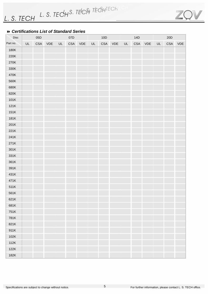
Certifications List of Standard Series 05D 07D 10D 14D 20D Disc
Part no. UL CSA VDE UL CSA VDE UL CSA VDE UL CSA VDE UL CSA VDE
180K ☆ ☆ ☆ ☆ ☆ ☆ ☆ ☆ ☆ ☆ ☆ ☆ ☆ ☆ ☆
220K ☆ ☆ ☆ ☆ ☆ ☆ ☆ ☆ ☆ ☆ ☆ ☆ ☆ ☆ ☆
270K ☆ ☆ ☆ ☆ ☆ ☆ ☆ ☆ ☆ ☆ ☆ ☆ ☆ ☆ ☆
330K ☆ ☆ ☆ ☆ ☆ ☆ ☆ ☆ ☆ ☆ ☆ ☆ ☆ ☆ ☆
470K ☆ ☆ ☆ ☆ ☆ ☆ ☆ ☆ ☆ ☆ ☆ ☆ ☆ ☆ ☆
560K ☆ ☆ ☆ ☆ ☆ ☆ ☆ ☆ ☆ ☆ ☆ ☆ ☆ ☆ ☆
680K ☆ ☆ ☆ ☆ ☆ ☆ ☆ ☆ ☆ ☆ ☆ ☆ ☆ ☆ ☆
820K ☆ ☆ ☆ ☆ ☆ ☆ ☆ ☆ ☆ ☆ ☆ ☆ ☆ ☆ ☆
101K ☆ ☆ ☆ ☆ ☆ ☆ ☆ ☆ ☆ ☆ ☆ ☆ ☆ ☆ ☆
121K ☆ ☆ ☆ ☆ ☆ ☆ ☆ ☆ ☆ ☆ ☆ ☆ ☆ ☆ ☆
151K ☆ ☆ ☆ ☆ ☆ ☆ ☆ ☆ ☆ ☆ ☆ ☆ ☆ ☆ ☆
181K ☆ ☆ ☆ ☆ ☆ ☆ ☆ ☆ ☆ ☆ ☆ ☆ ☆ ☆ ☆
201K ☆ ☆ ☆ ☆ ☆ ☆ ☆ ☆ ☆ ☆ ☆ ☆ ☆ ☆ ☆
221K ☆ ☆ ☆ ☆ ☆ ☆ ☆ ☆ ☆ ☆ ☆ ☆ ☆ ☆ ☆
241K ☆ ☆ ☆ ☆ ☆ ☆ ☆ ☆ ☆ ☆ ☆ ☆ ☆ ☆ ☆
271K ☆ ☆ ☆ ☆ ☆ ☆ ☆ ☆ ☆ ☆ ☆ ☆ ☆ ☆ ☆
301K ☆ ☆ ☆ ☆ ☆ ☆ ☆ ☆ ☆ ☆ ☆ ☆ ☆ ☆ ☆
331K ☆ ☆ ☆ ☆ ☆ ☆ ☆ ☆ ☆ ☆ ☆ ☆ ☆ ☆ ☆
361K ☆ ☆ ☆ ☆ ☆ ☆ ☆ ☆ ☆ ☆ ☆ ☆ ☆ ☆ ☆
391K ☆ ☆ ☆ ☆ ☆ ☆ ☆ ☆ ☆ ☆ ☆ ☆ ☆ ☆ ☆
431K ☆ ☆ ☆ ☆ ☆ ☆ ☆ ☆ ☆ ☆ ☆ ☆ ☆ ☆ ☆
471K ☆ ☆ ☆ ☆ ☆ ☆ ☆ ☆ ☆ ☆ ☆ ☆ ☆ ☆ ☆
511K ☆ ☆ ☆ ☆ ☆ ☆ ☆ ☆ ☆ ☆ ☆ ☆ ☆ ☆ ☆
561K ☆ ☆ ☆ ☆ ☆ ☆ ☆ ☆ ☆ ☆ ☆ ☆ ☆ ☆ ☆
621K ☆ ☆ ☆ ☆ ☆ ☆ ☆ ☆ ☆ ☆ ☆ ☆
681K ☆ ☆ ☆ ☆ ☆ ☆ ☆ ☆ ☆ ☆ ☆ ☆
751K ☆ ☆ ☆ ☆ ☆ ☆ ☆ ☆ ☆
781K ☆ ☆ ☆ ☆ ☆ ☆ ☆ ☆ ☆
821K ☆ ☆ ☆ ☆ ☆ ☆ ☆ ☆ ☆
911K ☆ ☆ ☆ ☆ ☆ ☆ ☆ ☆ ☆
102K ☆ ☆ ☆ ☆ ☆ ☆ ☆ ☆ ☆
112K ☆ ☆ ☆ ☆ ☆ ☆ ☆ ☆ ☆
122K ☆ ☆ ☆ ☆
182K ☆ ☆

6Specifications are subject to change without notice. For further information, please contact L. S. TECH office.
Taping Specification for 05D & 07D
Element Diameter Straight Leads Symbol Parameter (mm) 05D 07D
P Pitch of component 12.7±1.0 12.7±1.0
P0 Feed hole pitch 12.7±0.3 12.7±0.3
P1 Feed hole center to lead 3.85±0.7 3.85±0.7
P2 Hole center to component center 6.35±1.3 6.35±1.3
F Lead to lead distance 5.0±0.8 5.0±0.8
h Component alignment 0±2 0±2
W Tape width 18.0±1.0 18.0±1.0
Crimped Leads W0 Hold down tape width 12.0±1.0 12.0±1.0
W1 Hold position 9.0±0.5 9.0±0.5
W2 Hold down tape position Max. 3.0 Max. 3.0
H0 Height from tape center to component 16.0±1.0 16.0±1.0
H Height from tape center to component 20.0±2.0 20.0±2.0
I Length of clipped lead Max. 1.0 Max. 1.0
D0 Feed hole diameter 4.0±0.2 4.0±0.2
t Total tape thickness 0.6±0.3 0.6±0.3
B Height from tape center to component Max. 32 Max. 32
Taping Specification for 10D, 14D & 20D Element Diameter Straight Leads Symbol Parameter
(mm) 10D 14D 20DP Pitch of component 25.4±1.0 25.4±1.0 25.4±1.0
P0 Feed hole pitch 12.7±1.0 12.7±1.0 12.7±1.0
P1 Feed hole center to lead 8.95±0.7 8.95±0.7 7.7±0.7
P2 Hole center to component center 12.7±1.3 12.7±1.3 12.7±1.3
F Lead to lead distance 7.5±0.8 7.5±0.8 10±0.8
h Component alignment 0±2 0±4 0±4
W Tape width 18.0±1.0 18.0±1.0 18.0±1.0 W0 Hold down tape width 12.0±1.0 12.0±1.0 12.0±1.0 Crimped Leads
W1 Hold position 9.0±0.5 9.0±0.5 9.0±0.5
W2 Hold down tape position Max. 3.0 Max. 3.0 Max. 3.0
H0 Height from tape center to component 16.0±1.0 16.0±1.0 16.0±1.0
H Height from tape center to component 20.0±2.0 20.0±2.0 20.0±2.0
I Length of clipped lead Max. 1.0 Max. 1.0 Max. 1.0
D0 Feed hole diameter 4.0±0.2 4.0±0.2 4.0±0.2
t Total tape thickness 0.6±0.3 0.6±0.3 0.6±0.3
B Height from tape center to component Max. 36 Max. 40 Max. 45

7Specifications are subject to change without notice. For further information, please contact L. S. TECH office.
05D Specification Max.
Allowable Voltage
Varistor VoltageMax.
Clamping Voltage
Max. Peak Current Max. EnergyRated Power
Typical Capacitance
Max. Thickness
Certificate Status ZOV05D
Part No. Acrms
(V) DC (V)
V @ 1Ma (V)
VC (V)
IP (A)
@ 8/20µs
@ 10/1000µs(J)
(W)
@ 1 KHz (pf)
(mm)
UL CSA VDE
180K J 11 14 18 (15-21) 40 1 100 250 0.4 0.6 0.01 1400 4.5
220K J 14 18 22 (20-24) 48 1 100 250 0.5 0.7 0.01 1150 4.6
270K J 17 22 27 (24-30) 60 1 100 250 0.6 0.9 0.01 930 4.7
330K J 20 26 33 (30-36) 73 1 100 250 0.8 1.1 0.01 760 4.9
390K J 25 31 39 (35-43) 80 1 100 250 0.9 1.2 0.01 640 4.8
470K J 30 38 47 (42-52) 104 1 100 250 1.1 1.5 0.01 530 4.9
560K J 35 45 56 (50-62) 123 1 100 250 1.3 1.8 0.01 450 5.0
680K J 40 56 68 (61-75) 150 1 100 250 1.6 2.2 0.01 370 5.2
820K J 50 65 82 (74-90) 145 5 400 800 2.5 4.0 0.10 300 4.1
101K J 60 85 100 (90-110) 175 5 400 800 3.0 4.1 0.10 250 4.3
121K J 75 100 120 (108-132) 210 5 400 800 4.0 4.9 0.10 210 4.5
151K J 95 125 150 (135-165) 260 5 400 800 4.8 6.5 0.10 165 4.8
181K J 115 150 180 (162-198) 320 5 400 800 5.9 7.5 0.10 140 4.3
201K J 130 170 200 (185-225) 355 5 400 800 6.5 8.5 0.10 125 4.4
221K J 140 180 220 (198-242) 380 5 400 800 7.0 9.0 0.10 110 4.5
241K J 150 200 240 (216-264) 415 5 400 800 8.0 10.5 0.10 100 4.6
271K J 175 225 270 (243-297) 475 5 400 800 8.5 11.0 0.10 95 4.9
301K J 190 250 300 (270-330) 520 5 400 800 9.0 12.0 0.10 85 5.0
331K J 210 275 330 (297-363) 570 5 400 800 9.5 13.0 0.10 75 5.1
361K J 230 300 360 (324-396) 620 5 400 800 10.0 16.0 0.10 70 5.2
391K J 250 320 390 (351-429) 675 5 400 800 12.0 17.0 0.10 65 5.4
431K J 275 350 430 (387-473) 745 5 400 800 13.0 20.0 0.10 60 5.7
471K J 300 385 470 (423-517) 810 5 400 800 15.0 21.0 0.10 55 6.0
511K J 320 415 510 (459-561) 845 5 400 800 16.0 22.5 0.10 50 6.2
561K J 350 460 560 (504-616) 920 5 400 800 16.0 24.0 0.10 45 6.5
Note: Part no. with “J” represents high surge parts which values are highlighted in dark gray.
8Specifications are subject to change without notice. For further information, please contact L. S. TECH office.
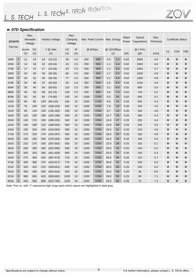
07D Specification Max.
Allowable Voltage
Varistor VoltageMax.
Clamping Voltage
Max. Peak Current Max. EnergyRated Power
Typical Capacitance
Max. Thickness
Certificate Status ZOV07D
Part No. Acrms
(V) DC (V)
V @ 1Ma (V)
VC (V)
IP (A)
@ 8/20µs
@ 10/1000µs(J)
(W)
@ 1 KHz (pf)
(mm)
UL CSA VDE
180K J 11 14 18 (15-21) 36 2.5 250 500 0.9 2.0 0.02 2800 4.5
220K J 14 18 22 (20-24) 43 2.5 250 500 1.1 2.4 0.02 2300 4.6
270K J 17 22 27 (24-30) 53 2.5 250 500 1.4 3.0 0.02 1800 4.7
330K J 20 26 33 (30-36) 65 2.5 250 500 1.7 3.5 0.02 1500 4.9
390K J 25 31 39 (35-43) 77 2.5 250 500 2.1 4.0 0.02 1300 4.8
470K J 30 38 47 (42-52) 93 2.5 250 500 2.5 5.0 0.02 1100 4.9
560K J 35 45 56 (50-62) 110 2.5 250 500 3.1 6.0 0.02 890 5.0
680K J 40 56 68 (61-75) 135 2.5 250 500 3.6 7.0 0.02 740 5.2
820K J 50 65 82 (74-90) 135 10 1200 1750 5.5 10 0.02 600 4.1
101K J 60 85 100 (90-110) 165 10 1200 1750 6.5 12 0.25 500 4.3
121K J 75 100 120 (108-132) 200 10 1200 1750 7.8 13 0.25 420 4.5
151K J 95 125 150 (135-165) 250 10 1200 1750 9.7 13 0.25 330 4.8
181K J 115 150 180 (162-198) 300 10 1200 1750 11.7 16 0.25 280 4.3
201K J 130 170 200 (185-225) 340 10 1200 1750 13.0 17 0.25 250 4.4
221K J 140 180 220 (198-242) 360 10 1200 1750 14.0 19 0.25 230 4.5
241K J 150 200 240 (216-264) 395 10 1200 1750 15.0 21 0.25 210 4.6
271K J 175 225 270 (243-297) 455 10 1200 1750 18.0 24 0.25 185 4.9
301K J 190 250 300 (270-330) 500 10 1200 1750 20.0 26 0.25 165 5.0
331K J 210 275 330 (297-363) 550 10 1200 1750 23.0 28 0.25 150 5.1
361K J 230 300 360 (324-396) 595 10 1200 1750 25.0 32 0.25 140 5.2
391K J 250 320 390 (351-429) 650 10 1200 1750 25.0 35 0.25 130 5.4
431K J 275 350 430 (387-473) 710 10 1200 1750 28.0 40 0.25 115 5.7
471K J 300 385 470 (423-517) 775 10 1200 1750 30.0 42 0.25 105 6.0
511K J 320 415 510 (459-561) 845 10 1200 1750 30.0 45 0.25 100 6.2
561K J 350 460 560 (504-616) 925 10 1200 1750 30.0 49 0.25 90 6.5
621K J 385 505 620 (558-682) 1025 10 1200 1750 33.0 55 0.25 80 7.1
681K J 420 560 680 (612-748) 1120 10 1200 1750 33.0 60 0.25 75 7.3
Note: Part no. with “J” represents high surge parts which values are highlighted in dark gray.

9Specifications are subject to change without notice. For further information, please contact L. S. TECH office.
10D Specification Max.
Allowable Voltage
Varistor VoltageMax.
Clamping Voltage
Max. Peak Current Max. EnergyRated Power
Typical Capacitance
Max. Thickness
Certificate Status ZOV10D
Part No. Acrms
(V) DC (V)
V @ 1Ma (V)
VC (V)
IP (A)
@ 8/20µs
@ 10/1000µs(J)
(W)
@ 1 KHz (pf)
(mm)
UL CSA VDE
180K J 11 14 18 (15-21) 36 5 500 1000 2.1 3.5 0.05 5600 4.6
220K J 14 18 22 (20-24) 43 5 500 1000 2.5 5.0 0.05 4500 4.7
270K J 17 22 27 (24-30) 53 5 500 1000 3.0 6.0 0.05 3700 4.8
330K J 20 26 33 (30-36) 65 5 500 1000 4.0 7.0 0.05 3000 5.0
390K J 25 31 39 (35-43) 77 5 500 1000 4.6 9.0 0.05 2400 5.3
470K J 30 38 47 (42-52) 93 5 500 1000 5.5 11.0 0.05 2100 5.4
560K J 35 45 56 (50-62) 110 5 500 1000 7.0 13.0 0.05 1800 5.5
680K J 40 56 68 (61-75) 135 5 500 1000 8.2 15.0 0.05 1500 5.6
820K J 50 65 82 (74-90) 135 25 2500 3500 12.0 17.0 0.40 1200 4.7
101K J 60 85 100 (90-110) 165 25 2500 3500 15.0 18.0 0.40 1000 4.9
121K J 75 100 120 (108-132) 200 25 2500 3500 18.0 21.0 0.40 830 5.1
151K J 95 125 150 (135-165) 250 25 2500 3500 22.0 25.0 0.40 670 5.4
181K J 115 150 180 (162-198) 300 25 2500 3500 27.0 30.0 0.40 560 4.8
201K J 130 170 200 (185-225) 340 25 2500 3500 30.0 35.0 0.40 500 5.0
221K J 140 180 220 (198-242) 360 25 2500 3500 32.0 39.0 0.40 450 5.1
241K J 150 200 240 (216-264) 395 25 2500 3500 35.0 42.0 0.40 420 5.2
271K J 175 225 270 (243-297) 455 25 2500 3500 40.0 49.0 0.40 370 5.4
301K J 190 250 300 (270-330) 500 25 2500 3500 40.0 54.0 0.40 330 5.5
331K J 210 275 330 (297-363) 550 25 2500 3500 43.0 58.0 0.40 300 5.8
361K J 230 300 360 (324-396) 595 25 2500 3500 47.0 65.0 0.40 280 6.0
391K J 250 320 390 (351-429) 650 25 2500 3500 60.0 70.0 0.40 260 6.2
431K J 275 350 430 (387-473) 710 25 2500 3500 65.0 80.0 0.40 230 6.5
471K J 300 385 470 (423-517) 775 25 2500 3500 70.0 85.0 0.40 210 6.7
511K J 320 415 510 (459-561) 845 25 2500 3500 70.0 90.0 0.40 200 6.8
561K J 350 460 560 (504-616) 925 25 2500 3500 70.0 92.0 0.40 180 7.0
621K J 385 505 620 (558-682) 1025 25 2500 3500 70.0 95.0 0.40 160 7.3
681K J 420 560 680 (612-748) 1120 25 2500 3500 70.0 98.0 0.40 150 7.6
751K J 460 615 750 (675-825) 1240 25 2500 3500 75.0 100.0 0.40 130 8.0
781K J 485 640 780 (702-858) 1290 25 2500 3500 80.0 105.0 0.40 130 8.1
821K J 510 670 820 (738-902) 1355 25 2500 3500 85.0 110.0 0.40 120 8.3
911K J 550 745 910 (819-1001) 1500 25 2500 3500 93.0 130.0 0.40 110 8.8
102K J 625 825 1000 (900-1100) 1650 25 2500 3500 102.0 140.0 0.40 100 9.3
112K J 680 895 1100 (990-1210) 1815 25 2500 3500 115.0 155.0 0.40 90 9.9
Note: Part no. with “J” represents high surge parts which values are highlighted in dark gray.

10Specifications are subject to change without notice. For further information, please contact L. S. TECH office.
14D Specification Max.
Allowable Voltage
Varistor VoltageMax.
Clamping Voltage
Max. Peak Current Max. EnergyRated Power
Typical Capacitance
Max. Thickness
Certificate Status ZOV14D
Part No. Acrms
(V) DC (V)
V @ 1Ma (V)
VC (V)
IP (A)
@ 8/20µs
@ 10/1000µs(J)
(W)
@ 1 KHz (pf)
(mm)
UL CSA VDE
180K J 11 14 18 (15-21) 36 10 1000 2000 4 7 0.1 11100 4.6
220K J 14 18 22 (20-24) 43 10 1000 2000 5 8 0.1 9100 4.7
270K J 17 22 27 (24-30) 53 10 1000 2000 6 10 0.1 7400 4.8
330K J 20 26 33 (30-36) 65 10 1000 2000 7 12 0.1 6100 5.0
390K J 25 31 39 (35-43) 77 10 1000 2000 8 13 0.1 5100 5.3
470K J 30 38 47 (42-52) 93 10 1000 2000 10 17 0.1 4300 5.4
560K J 35 45 56 (50-62) 110 10 1000 2000 11 20 0.1 3600 5.5
680K J 40 56 68 (61-75) 135 10 1000 2000 14 24 0.1 2900 5.6
820K J 50 65 82 (74-90) 135 50 4500 6000 22 27 0.6 2400 4.7
101K J 60 85 100 (90-110) 165 50 4500 6000 28 33 0.6 2000 4.9
121K J 75 100 120 (108-132) 200 50 4500 6000 32 40 0.6 1700 5.1
151K J 95 125 150 (135-165) 250 50 4500 6000 40 53 0.6 1300 5.4
181K J 115 150 180 (162-198) 300 50 4500 6000 50 60 0.6 1100 4.8
201K J 130 170 200 (185-225) 340 50 4500 6000 57 70 0.6 1000 5.0
221K J 140 180 220 (198-242) 360 50 4500 6000 60 78 0.6 900 5.1
241K J 150 200 240 (216-264) 395 50 4500 6000 63 84 0.6 830 5.2
271K J 175 225 270 (243-297) 455 50 4500 6000 70 99 0.6 740 5.4
301K J 190 250 300 (270-330) 500 50 4500 6000 77 108 0.6 670 5.5
331K J 210 275 330 (297-363) 550 50 4500 6000 85 115 0.6 610 5.8
361K J 230 300 360 (324-396) 595 50 4500 6000 93 130 0.6 560 6.0
391K J 250 320 390 (351-429) 650 50 4500 6000 100 140 0.6 510 6.2
431K J 275 350 430 (387-473) 710 50 4500 6000 115 155 0.6 460 6.5
471K J 300 385 470 (423-517) 775 50 4500 6000 125 175 0.6 430 6.7
511K J 320 415 510 (459-561) 845 50 4500 6000 125 180 0.6 390 6.8
561K J 350 460 560 (504-616) 925 50 4500 6000 125 185 0.6 360 7.0
621K J 385 505 620 (558-682) 1025 50 4500 6000 125 190 0.6 320 7.3
681K J 420 560 680 (612-748) 1120 50 4500 6000 130 200 0.6 290 7.6
751K J 460 615 750 (675-825) 1240 50 4500 6000 143 210 0.6 270 8.0
781K J 485 640 780 (702-858) 1290 50 4500 6000 148 220 0.6 260 8.1
821K J 510 670 820 (738-902) 1355 50 4500 6000 157 235 0.6 240 8.3
911K J 550 745 910 (819-1001) 1500 50 4500 6000 175 255 0.6 220 8.8
102K J 625 825 1000 (900-1100) 1650 50 4500 6000 190 280 0.6 200 9.3
112K J 680 895 1100 (990-1210) 1815 50 4500 6000 213 310 0.6 180 9.9
122K J 750 990 1200 (1080-1320 1980 50 4500 6000 213 310 0.6 150 10.4
182K J 1100 1465 1800 (1620-1980 2970 50 5000 6000 250 335 0.6 130 13.0
Note: Part no. with “J” represents high surge parts which values are highlighted in dark gray.

11Specifications are subject to change without notice. For further information, please contact L. S. TECH office.
20D Specification Max.
Allowable Voltage
Varistor VoltageMax.
Clamping Voltage
Max. Peak Current Max. EnergyRated Power
Typical Capacitance
Max. Thickness
Certificate Status ZOV20D
Part No. Acrms
(V) DC (V)
V @ 1Ma (V)
VC (V)
IP (A)
@ 8/20µs
@ 10/1000µs(J)
(W)
@ 1 KHz (pf)
(mm)
UL CSA VDE
180K J 11 14 18 (15-21) 36 20 2000 3000 11 13 0.2 28500 4.8
220K J 14 18 22 (20-24) 43 20 2000 3000 14 16 0.2 18500 4.9
270K J 17 22 27 (24-30) 53 20 2000 3000 16 19 0.2 13000 5.0
330K J 20 26 33 (30-36) 65 20 2000 3000 23 24 0.2 11500 5.2
390K J 25 31 39 (35-43) 77 20 2000 3000 26 28 0.2 8500 5.5
470K J 30 38 47 (42-52) 93 20 2000 3000 30 34 0.2 7400 5.6
560K J 35 45 56 (50-62) 110 20 2000 3000 41 41 0.2 6500 5.7
680K J 40 56 68 (61-75) 135 20 2000 3000 46 49 0.2 5800 5.8
820K J 50 65 82 (74-90) 135 100 6500 10000 38 56 1.0 4900 4.9
101K J 60 85 100 (90-110) 165 100 6500 10000 45 70 1.0 4000 5.1
121K J 75 100 120 (108-132) 200 100 6500 10000 55 85 1.0 3300 5.3
151K J 95 125 150 (135-165) 250 100 6500 10000 70 106 1.0 2700 5.6
181K J 115 150 180 (162-198) 300 100 6500 10000 85 130 1.0 2200 5.0
201K J 130 170 200 (185-225) 340 100 6500 10000 95 140 1.0 2000 5.2
221K J 140 180 220 (198-242) 360 100 6500 10000 100 155 1.0 1800 5.3
241K J 150 200 240 (216-264) 395 100 6500 10000 108 168 1.0 1650 5.4
271K J 175 225 270 (243-297) 455 100 6500 10000 127 190 1.0 1500 5.6
301K J 190 250 300 (270-330) 500 100 6500 10000 136 210 1.0 1300 5.7
331K J 210 275 330 (297-363) 550 100 6500 10000 150 228 1.0 1200 6.0
361K J 230 300 360 (324-396) 595 100 6500 10000 163 255 1.0 1100 6.2
391K J 250 320 390 (351-429) 650 100 6500 10000 180 275 1.0 1000 6.4
431K J 275 350 430 (387-473) 710 100 6500 10000 190 305 1.0 930 6.7
471K J 300 385 470 (423-517) 775 100 6500 10000 220 350 1.0 850 6.9
511K J 320 415 510 (459-561) 845 100 6500 1000 220 360 1.0 780 7.0
561K J 350 460 560 (504-616) 925 100 6500 1000 220 380 1.0 710 7.2
621K J 385 505 620 (558-682) 1025 100 6500 1000 220 390 1.0 650 7.5
681K J 420 560 680 (612-748) 1120 100 6500 10000 230 400 1.0 600 7.8
751K J 460 615 750 (675-825) 1240 100 6500 10000 255 420 1.0 530 8.2
781K J 485 640 780 (702-858) 1290 100 6500 10000 265 440 1.0 510 8.3
821K J 510 670 820 (738-902) 1355 100 6500 10000 282 460 1.0 500 8.5
911K J 550 745 910 (819-1001) 1500 100 6500 10000 310 510 1.0 440 9.0
102K J 625 825 1000 (900-1100) 1650 100 6500 10000 342 565 1.0 400 9.5
112K J 680 895 1100 (990-1210) 1815 100 6500 10000 383 620 1.0 360 10.1
122K J 750 990 1200 (1080-1320 1980 100 6500 10000 408 660 1.0 320 10.6
182K J 1100 1465 1800 (1620-1980 2970 100 6500 10000 625 660 1.0 320 13.2
Note: Part no. with “J” represents high surge parts which values are highlighted in dark gray.
12Specifications are subject to change without notice. For further information, please contact L. S. TECH office.
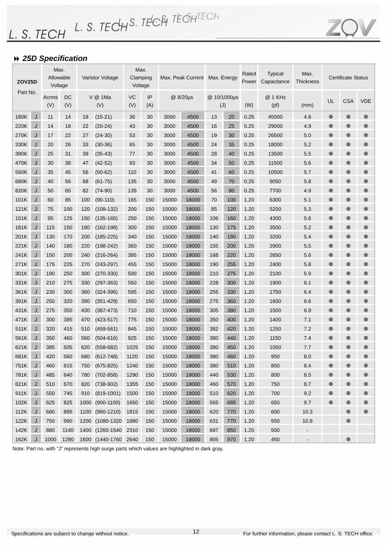
25D Specification Max.
Allowable Voltage
Varistor VoltageMax.
Clamping Voltage
Max. Peak Current Max. EnergyRated Power
Typical Capacitance
Max. Thickness
Certificate Status ZOV25D
Part No. Acrms
(V) DC (V)
V @ 1Ma (V)
VC (V)
IP (A)
@ 8/20µs
@ 10/1000µs(J)
(W)
@ 1 KHz (pf)
(mm)
UL CSA VDE
180K J 11 14 18 (15-21) 36 30 3000 4500 13 20 0.25 45000 4.8
220K J 14 18 22 (20-24) 43 30 3000 4500 16 25 0.25 29000 4.9
270K J 17 22 27 (24-30) 53 30 3000 4500 19 30 0.25 26500 5.0
330K J 20 26 33 (30-36) 65 30 3000 4500 24 35 0.25 18000 5.2
390K J 25 31 39 (35-43) 77 30 3000 4500 28 40 0.25 13500 5.5
470K J 30 38 47 (42-52) 93 30 3000 4500 34 50 0.25 11500 5.6
560K J 35 45 56 (50-62) 110 30 3000 4500 41 60 0.25 10500 5.7
680K J 40 56 68 (61-75) 135 30 3000 4500 49 70 0.25 9050 5.8
820K J 50 65 82 (74-90) 135 30 3000 4500 56 80 0.25 7700 4.9
101K J 60 85 100 (90-110) 165 150 15000 18000 70 100 1.20 6300 5.1
121K J 75 100 120 (108-132) 200 150 15000 18000 85 120 1.20 5200 5.3
151K J 95 125 150 (135-165) 250 150 15000 18000 106 160 1.20 4300 5.6
181K J 115 150 180 (162-198) 300 150 15000 18000 130 175 1.20 3500 5.2
201K J 130 170 200 (185-225) 340 150 15000 18000 140 190 1.20 3200 5.4
221K J 140 180 220 (198-242) 360 150 15000 18000 155 200 1.20 2900 5.5
241K J 150 200 240 (216-264) 395 150 15000 18000 168 220 1.20 2650 5.6
271K J 175 225 270 (243-297) 455 150 15000 18000 190 255 1.20 2400 5.8
301K J 190 250 300 (270-330) 500 150 15000 18000 210 275 1.20 2100 5.9
331K J 210 275 330 (297-363) 550 150 15000 18000 228 300 1.20 1900 6.1
361K J 230 300 360 (324-396) 595 150 15000 18000 255 330 1.20 1750 6.4
391K J 250 320 390 (351-429) 650 150 15000 18000 275 360 1.20 1600 6.6
431K J 275 350 430 (387-473) 710 150 15000 18000 305 380 1.20 1500 6.9
471K J 300 385 470 (423-517) 775 150 15000 18000 350 400 1.20 1400 7.1
511K J 320 415 510 (459-561) 845 150 15000 18000 382 420 1.20 1250 7.2
561K J 350 460 560 (504-616) 925 150 15000 18000 380 440 1.20 1150 7.4
621K J 385 505 620 (558-682) 1025 150 15000 18000 380 450 1.20 1050 7.7
681K J 420 560 680 (612-748) 1120 150 15000 18000 380 460 1.20 950 8.0
751K J 460 615 750 (675-825) 1240 150 15000 18000 380 510 1.20 850 8.4
781K J 485 640 780 (702-858) 1290 150 15000 18000 440 530 1.20 800 8.5
821K J 510 670 820 (738-902) 1355 150 15000 18000 460 570 1.20 750 8.7
911K J 550 745 910 (819-1001) 1500 150 15000 18000 510 620 1.20 700 9.2
102K J 625 825 1000 (900-1100) 1650 150 15000 18000 565 685 1.20 650 9.7
112K J 680 895 1100 (990-1210) 1815 150 15000 18000 620 770 1.20 600 10.3
122K J 750 990 1200 (1080-1320 1980 150 15000 18000 631 770 1.20 550 10.8
142K J 880 1140 1400 (1260-1540 2310 150 15000 18000 697 850 1.20 500 -
162K J 1000 1280 1600 (1440-1760 2640 150 15000 18000 805 970 1.20 450 -
Note: Part no. with “J” represents high surge parts which values are highlighted in dark gray.

13Specifications are subject to change without notice. For further information, please contact L. S. TECH office.
32D Specification
32D Dimension D 38.0 Max.
H 56.3 Max.
T See above chart Max.
F 25.4 ±0.5
t 0.5 ±0.1
L 16.5 Min.
K 3.18 Max.
W 7.0 ±0.5
ψ 3.8 M3±0.2
Max. Allowable Voltage
Varistor Voltage Max. Clamping
Voltage Max. Peak Current
@ 8/20µs Max. Energy@ 10/1000µs
Typical Capacitance
Max. Thickness
Certificate Status ZOV32D
Part No. Acrms (V)
DC (V)
V @ 1Ma (V)
VC (V)
IP(A)
1 time
(A)
2 times
(A)
@10/1000µs(J)
@ 1 KHz (pf)
(mm)
UL CSA
201K 130 170 200 (185-225) 340 200 25000 20000 250 5200 6.2
221K 140 180 220 (198-242) 395 200 25000 20000 290 5100 6.4
241K 150 200 240 (216-264) 455 200 25000 20000 300 4800 6.6
271K 175 225 270 (243-297) 550 200 25000 20000 360 4300 6.9
331K 210 275 330 (297-363) 595 200 25000 20000 380 3900 7.1
361K 230 300 360 (324-396) 650 200 25000 20000 400 3200 7.3
391K 250 320 390 (351-429) 710 200 25000 20000 430 3100 7.5
431K 275 350 430 (387-473) 775 200 25000 20000 460 2800 7.8
471K 300 385 470 (423-517) 845 200 25000 20000 510 2700 8.0
511K 320 415 510 (459-561) 1025 200 25000 20000 570 2400 8.7
621K 385 505 620 (558-682) 1120 200 25000 20000 600 2200 9.0
681K 420 560 680 (612-748) 1240 200 25000 20000 620 2000 9.4
751K 460 615 750 (675-825) 1290 200 25000 20000 660 1900 9.6
781K 485 640 780 (702-858) 1355 200 25000 20000 700 1800 9.8
821K 510 670 820 (738-902) 1500 200 25000 20000 750 1300 10.4
911K 550 745 910 (819-1001) 1570 200 25000 20000 780 1200 10.6
102K 625 825 1000 (900-1100) 1650 200 25000 20000 810 1100 11.2
112K 680 895 1100 (990-1210) 1815 200 25000 20000 910 1000 11.8
122K 750 990 1200 (1080-1320) 1980 200 25000 20000 960 920 12.3
142K 880 1140 1400 (1260-1540) 2310 200 25000 20000 1020 800 13.3
162K 1000 1280 1600 (1440-1760) 2640 200 25000 20000 1080 700 14.3
14Specifications are subject to change without notice. For further information, please contact L. S. TECH office.
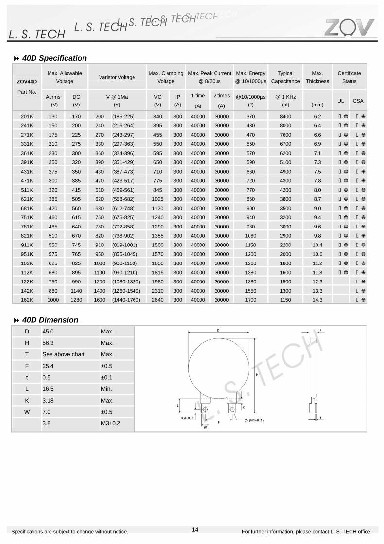
40D Specification
40D Dimension D 45.0 Max.
H 56.3 Max.
T See above chart Max.
F 25.4 ±0.5
t 0.5 ±0.1
L 16.5 Min.
K 3.18 Max.
W 7.0 ±0.5
ψ 3.8 M3±0.2
Max. Allowable Voltage
Varistor Voltage Max. Clamping
Voltage Max. Peak Current
@ 8/20µs Max. Energy@ 10/1000µs
Typical Capacitance
Max. Thickness
Certificate Status ZOV40D
Part No. Acrms (V)
DC (V)
V @ 1Ma (V)
VC (V)
IP(A)
1 time
(A)
2 times
(A)
@10/1000µs(J)
@ 1 KHz (pf)
(mm)
UL CSA
201K 130 170 200 (185-225) 340 300 40000 30000 370 8400 6.2
241K 150 200 240 (216-264) 395 300 40000 30000 430 8000 6.4
271K 175 225 270 (243-297) 455 300 40000 30000 470 7600 6.6
331K 210 275 330 (297-363) 550 300 40000 30000 550 6700 6.9
361K 230 300 360 (324-396) 595 300 40000 30000 570 6200 7.1
391K 250 320 390 (351-429) 650 300 40000 30000 590 5100 7.3
431K 275 350 430 (387-473) 710 300 40000 30000 660 4900 7.5
471K 300 385 470 (423-517) 775 300 40000 30000 720 4300 7.8
511K 320 415 510 (459-561) 845 300 40000 30000 770 4200 8.0
621K 385 505 620 (558-682) 1025 300 40000 30000 860 3800 8.7
681K 420 560 680 (612-748) 1120 300 40000 30000 900 3500 9.0
751K 460 615 750 (675-825) 1240 300 40000 30000 940 3200 9.4
781K 485 640 780 (702-858) 1290 300 40000 30000 980 3000 9.6
821K 510 670 820 (738-902) 1355 300 40000 30000 1080 2900 9.8
911K 550 745 910 (819-1001) 1500 300 40000 30000 1150 2200 10.4
951K 575 765 950 (855-1045) 1570 300 40000 30000 1200 2000 10.6
102K 625 825 1000 (900-1100) 1650 300 40000 30000 1260 1800 11.2
112K 680 895 1100 (990-1210) 1815 300 40000 30000 1380 1600 11.8
122K 750 990 1200 (1080-1320) 1980 300 40000 30000 1380 1500 12.3
142K 880 1140 1400 (1260-1540) 2310 300 40000 30000 1550 1300 13.3
162K 1000 1280 1600 (1440-1760) 2640 300 40000 30000 1700 1150 14.3

15Specifications are subject to change without notice. For further information, please contact L. S. TECH office.
53D Specification
53D Dimension D 60.0 Max.
H 78.2 Max.
T See above chart Max.
F 25.4 ±0.5
t 0.7 ±0.1
L 16.5 Min.
K 3.18 Max.
W 9.7 ±0.5
ψ 4.15 M3±0.2
Max. Allowable Voltage
Varistor Voltage Max. Clamping
Voltage Max. Peak Current
@ 8/20µs Max. Energy@ 10/1000µs
Typical Capacitance
Max. Thickness
Certificate Status ZOV40D
Part No. Acrms (V)
DC (V)
V @ 1Ma (V)
VC (V)
IP(A)
1 time
(A)
2 times
(A)
@10/1000µs(J)
@ 1 KHz (pf)
(mm)
UL CSA
201K 130 170 200 (185-225) 340 500 70000 50000 550 15000 6.3
241K 150 200 240 (216-264) 395 500 70000 50000 650 12500 6.5
271K 175 225 270 (243-297) 455 500 70000 50000 700 1000 6.7
331K 210 275 330 (297-363) 550 500 70000 50000 825 9000 7.0
361K 230 300 360 (324-396) 595 500 70000 50000 850 8500 7.2
391K 250 320 390 (351-429) 650 500 70000 50000 885 7500 7.4
431K 275 350 430 (387-473) 710 500 70000 50000 990 7000 7.6
471K 300 385 470 (423-517) 775 500 70000 50000 1080 6500 7.9
511K 320 415 510 (459-561) 845 500 70000 50000 1150 6000 8.1
621K 385 505 620 (558-682) 1025 500 70000 50000 1300 5000 8.8
681K 420 560 680 (612-748) 1120 500 70000 50000 1350 4500 9.1
751K 460 615 750 (675-825) 1240 500 70000 50000 1400 4000 9.5
781K 485 640 780 (702-858) 1290 500 70000 50000 1400 3900 9.7
821K 510 670 820 (738-902) 1355 500 70000 50000 1600 3700 9.9
911K 550 745 910 (819-1001) 1500 500 70000 50000 1700 3300 10.5
951K 575 765 950 (855-1045) 1570 500 70000 50000 1800 3200 10.7
102K 625 825 1000 (900-1100) 1650 500 70000 50000 1890 3000 11.3
112K 680 895 1100 (990-1210) 1815 500 70000 50000 2050 2700 11.9
122K 750 990 1200 (1080-1320) 1980 500 70000 50000 2050 2500 12.4
142K 880 1140 1400 (1260-1540) 2310 500 70000 50000 2300 2150 13.4
162K 1000 1280 1600 (1440-1760) 2640 500 70000 50000 2500 1900 14.4
16Specifications are subject to change without notice. For further information, please contact L. S. TECH office.
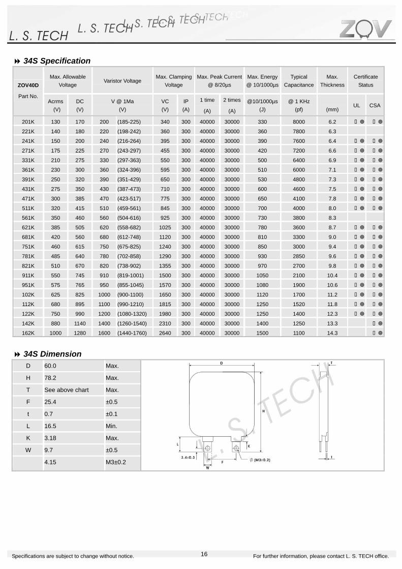
34S Specification
34S Dimension D 60.0 Max.
H 78.2 Max.
T See above chart Max.
F 25.4 ±0.5
t 0.7 ±0.1
L 16.5 Min.
K 3.18 Max.
W 9.7 ±0.5
ψ 4.15 M3±0.2
Max. Allowable Voltage
Varistor Voltage Max. Clamping
Voltage Max. Peak Current
@ 8/20µs Max. Energy@ 10/1000µs
Typical Capacitance
Max. Thickness
Certificate Status ZOV40D
Part No. Acrms (V)
DC (V)
V @ 1Ma (V)
VC (V)
IP(A)
1 time
(A)
2 times
(A)
@10/1000µs(J)
@ 1 KHz (pf)
(mm)
UL CSA
201K 130 170 200 (185-225) 340 300 40000 30000 330 8000 6.2
221K 140 180 220 (198-242) 360 300 40000 30000 360 7800 6.3
241K 150 200 240 (216-264) 395 300 40000 30000 390 7600 6.4
271K 175 225 270 (243-297) 455 300 40000 30000 420 7200 6.6
331K 210 275 330 (297-363) 550 300 40000 30000 500 6400 6.9
361K 230 300 360 (324-396) 595 300 40000 30000 510 6000 7.1
391K 250 320 390 (351-429) 650 300 40000 30000 530 4800 7.3
431K 275 350 430 (387-473) 710 300 40000 30000 600 4600 7.5
471K 300 385 470 (423-517) 775 300 40000 30000 650 4100 7.8
511K 320 415 510 (459-561) 845 300 40000 30000 700 4000 8.0
561K 350 460 560 (504-616) 925 300 40000 30000 730 3800 8.3
621K 385 505 620 (558-682) 1025 300 40000 30000 780 3600 8.7
681K 420 560 680 (612-748) 1120 300 40000 30000 810 3300 9.0
751K 460 615 750 (675-825) 1240 300 40000 30000 850 3000 9.4
781K 485 640 780 (702-858) 1290 300 40000 30000 930 2850 9.6
821K 510 670 820 (738-902) 1355 300 40000 30000 970 2700 9.8
911K 550 745 910 (819-1001) 1500 300 40000 30000 1050 2100 10.4
951K 575 765 950 (855-1045) 1570 300 40000 30000 1080 1900 10.6
102K 625 825 1000 (900-1100) 1650 300 40000 30000 1120 1700 11.2
112K 680 895 1100 (990-1210) 1815 300 40000 30000 1250 1520 11.8
122K 750 990 1200 (1080-1320) 1980 300 40000 30000 1250 1400 12.3
142K 880 1140 1400 (1260-1540) 2310 300 40000 30000 1400 1250 13.3
162K 1000 1280 1600 (1440-1760) 2640 300 40000 30000 1500 1100 14.3

17Specifications are subject to change without notice. For further information, please contact L. S. TECH office.
Terminology and General Characteristics Definition Electrical
Characteristics Description
Standard Test Condition Environmental conditions under which every measuring is done without doubt on
the measurement results unless specially specified. Temperature relative
humidity is 5°C to 35°C, 45% to 85% RH.
N/A.
Maximum Allowable
Voltage
The maximum sinusoidal RMS voltage or maximum DC voltage that can be
applied continuously in the specified environmental temperature range.
To meet the
specified value.
Varistor Voltage The voltage between two terminals with the specified measuring current CmA DC
applied is called Vc or VcmA, the measurement shall be made as fast as possible
to avoid heat affection.
To meet the
specified value.
Clamping Voltage The maximum voltage between two terminals with the specified standard impulse
current(8/20 µS) illustrated below applied.
To meet the
specified value.
1 time The maximum current within the varistor voltage change of ±10% with the
standard impulse current(8/20 µS) applied one time.
To meet the
specified value.
Maximum
Peak
Current 2 times The maximum current within the varistor± voltage change of ±10% with the
standard impulse current(8/20 µS) applied two times with an interval of 5 minutes.
To meet the
specified value.
Maximum Energy The maximum energy within the varistor voltage change of ±10% when one
impulse of 2 ms or 10/1000 µS is applied.
To meet the
specified value.
Rated Power The power that can be applied in the specified ambient temperature. To meet the
specified value.
Capacitance Capacitance shall be measured at 1 kHz±10%, 1Vrms max.(1 MHz below 100pF)
0v bias and 20±2°C.
To meet the
specified value.
Dissipation Factor Dissipation factor shall be measured at 1kHz±10%, 1Vrms max.(1 MHz±10%
below 100pF). 0V bias and 20±2°C.
To meet the
specified value.
Temperature Coefficient of
Varistor Voltage
(Vc at 85°C – Vc at 25°C) / Vc at 25°C * 1/60 * 100(% / °C) ±0.05% / °C
max.
The specified voltage shall be applied both terminals of the specimen connected
together and metal foil closely wrapped around its body for 1 minute. Electrical
breakdown shall be examined.
Classification
(Nominal varistor voltage)
Test Voltage
(AC)
V0.1mA. V1mA ≦ 330V 1000 Vrms
V0.1mA. V1mA > 330V 1500 Vrms
Withstanding
Voltage(Body Insulation)
No breakdown.
DC Leakage Current Maximum current with rated DC voltage applied. (Tested by 80% of breakdown
voltage).
200 μA max.
Current / Energy Derating Derating of maximum values when operating above 85°C. -2.5% / °C

18Specifications are subject to change without notice. For further information, please contact L. S. TECH office.
Terminology and General Characteristics Definition Electrical
Characteristics Description
The change of Vc shall be measured after the impulse listed below is applied
10000 times continuously with the interval of ten seconds at room temperature.
180K ~ 680K 8A (8/20μs) 05D series 820K ~ 561K 40A (8/20μs)
180K ~ 680K 25A (8/20μs) 07D series 820K ~ 681K 100A (8/20μs)
180K ~ 680K 50A (8/20μs) 10D series
820K ~ 112K 150A (8/20μs)
180K ~ 680K 90A (8/20μs)
820K ~ 112K 300A (8/20μs)
14D series
182K 150A (8/20μs)
180K ~ 680K 130A (8/20μs)
820K ~ 122K 250A (8/20μs)
20D series
182K 200A (8/20μs)
Impulse Life (I)
ΔVcmA / VcmA ≦
±10%
The change of Vc shall be measured after the impulse listed below is applied
100000 times continuously with the interval of ten seconds at room
temperature.
180K ~ 680K 5A (8/20μs) 05D series 820K ~ 561K 25A (8/20μs)
180K ~ 680K 15A (8/20μs) 07D series 820K ~ 681K 60A (8/20μs)
180K ~ 680K 35A (8/20μs) 10D series
820K ~ 112K 85A (8/20μs)
180K ~ 680K 50A (8/20μs)
820K ~ 112K 110A (8/20μs)
14D series
182K 80A (8/20μs)
180K ~ 680K 65A (8/20μs)
820K ~ 122K 120A (8/20μs)
20D series
182K 90A (8/20μs)
Impulse Life (I)
ΔVcmA / VcmA ≦
±10%
Impulse Response Time Time lag between application of surge and varistor’s “turn-on” conduction
action .
< 50 nanoseconds
05D ~ 25D
Voltage α min.180 ~ 330K 18
390 ~ 680K 20
820 ~ 151K 30
181 ~ 112K 40
Non Linear Exponent(α) The varistor voltage-current characteristic is defined by the equation I=KVα
where K is a constant dependent on geometry andα is the non linear
exponent. We usually take two points (V1, I1), (V2, I2) to estimate the value ofα.
α=(Log I1/I2) / (Log V1/V2), in which I1 and I2 are the current value,
corresponding to the voltage value V1 and V2.
19Specifications are subject to change without notice. For further information, please contact L. S. TECH office.
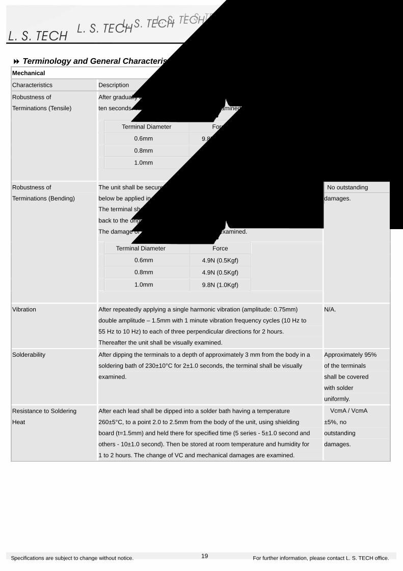
Terminology and General Characteristics Definition
Mechanical
Characteristics Description
After gradually applying the force specified below and keeping the unit fixed for
ten seconds. The terminal shall be visually examined for any damage.
Terminal Diameter Force
φ0.6mm 9.8N (1.0Kgf)
φ0.8mm 9.8N (1.0Kgf)
φ1.0mm 19.6N (2.0Kgf)
Robustness of
Terminations (Tensile)
No outstanding
damages.
The unit shall be secured with its terminal kept vertical and the force specified
below be applied in the axial direction.
The terminal shall gradually be bent by 90° in the opposite direction, and again
back to the original position.
The damage of the terminal shall be visually examined.
Terminal Diameter Force
φ0.6mm 4.9N (0.5Kgf)
φ0.8mm 4.9N (0.5Kgf)
φ1.0mm 9.8N (1.0Kgf)
Robustness of
Terminations (Bending)
No outstanding
damages.
Vibration After repeatedly applying a single harmonic vibration (amplitude: 0.75mm)
double amplitude – 1.5mm with 1 minute vibration frequency cycles (10 Hz to
55 Hz to 10 Hz) to each of three perpendicular directions for 2 hours.
Thereafter the unit shall be visually examined.
N/A.
Solderability After dipping the terminals to a depth of approximately 3 mm from the body in a
soldering bath of 230±10°C for 2±1.0 seconds, the terminal shall be visually
examined.
Approximately 95%
of the terminals
shall be covered
with solder
uniformly.
Resistance to Soldering
Heat
After each lead shall be dipped into a solder bath having a temperature
260±5°C, to a point 2.0 to 2.5mm from the body of the unit, using shielding
board (t=1.5mm) and held there for specified time (5 series - 5±1.0 second and
others - 10±1.0 second). Then be stored at room temperature and humidity for
1 to 2 hours. The change of VC and mechanical damages are examined.
ΔVcmA / VcmA ≦
±5%, no
outstanding
damages.

20Specifications are subject to change without notice. For further information, please contact L. S. TECH office.
Terminology and General Characteristics Definition Environmental
Characteristics Description Specifications
High Temperature Storage
/ Dry Heat
The specimen shall be subjected to 125±2°C for 1000 hours in a thermostatic
bath without load and then stored at room temperature and humidity for 1 to 2
hours. Thereafter the change of Vc shall be measured.
ΔVcmA / VcmA ≦
±5%
Damp Heat / Humidity
(Steady State)
The specimen shall be subjected to 40±2°C at 90 to 95% RH for 1000 hours
without load and then stored at room temperature and humidity for 1 to 2
hours. Thereafter the change of Vc shall be measured.
ΔVcmA / VcmA ≦
±5%
The temperature cycle shown below shall be repeated five times and then
stored at room temperature and humidity for 1 to 2 hours. Thereafter the
change of Vc and mechanical damages shall be examined.
Step Temperature Period
1 -40±3°C 30±3.0 min.
2 Room temperature 15±3.0 min.
3 125±2°C 30±3.0 min.
4 Room temperature 15±3.0 min.
Temperature Cycle
ΔVcmA / VcmA ≦
±5%
High Temperature Load /
Dry Heat Load
After being continuously applied the maximum allowable voltage at 85±2°C for
1000 hours, the specimen shall be stored at room temperature and humidity for
1 to 2 hours. Thereafter the change of Vc shall be measured.
ΔVcmA / VcmA ≦
±10%
Damp Heat Load /
Humidity Load
The specimen shall be subjected to 40±2°C at 90 to 95% RH and maximum
allowable voltage for 1000 hours and then stored at room temperature and
humidity for 1 to 2 hours. Thereafter the change of Vc shall be measured.
ΔVcmA / VcmA ≦
±10%
Low Temperature Storage
/ Cold
The specimen shall be subjected to -40±2°C without load for 1000 hours and
then stored at room temperature for 1 to 2 hours. Thereafter the change of Vc
shall be measured.
ΔVcmA / VcmA ≦
±5%
21Specifications are subject to change without notice. For further information, please contact L. S. TECH office.
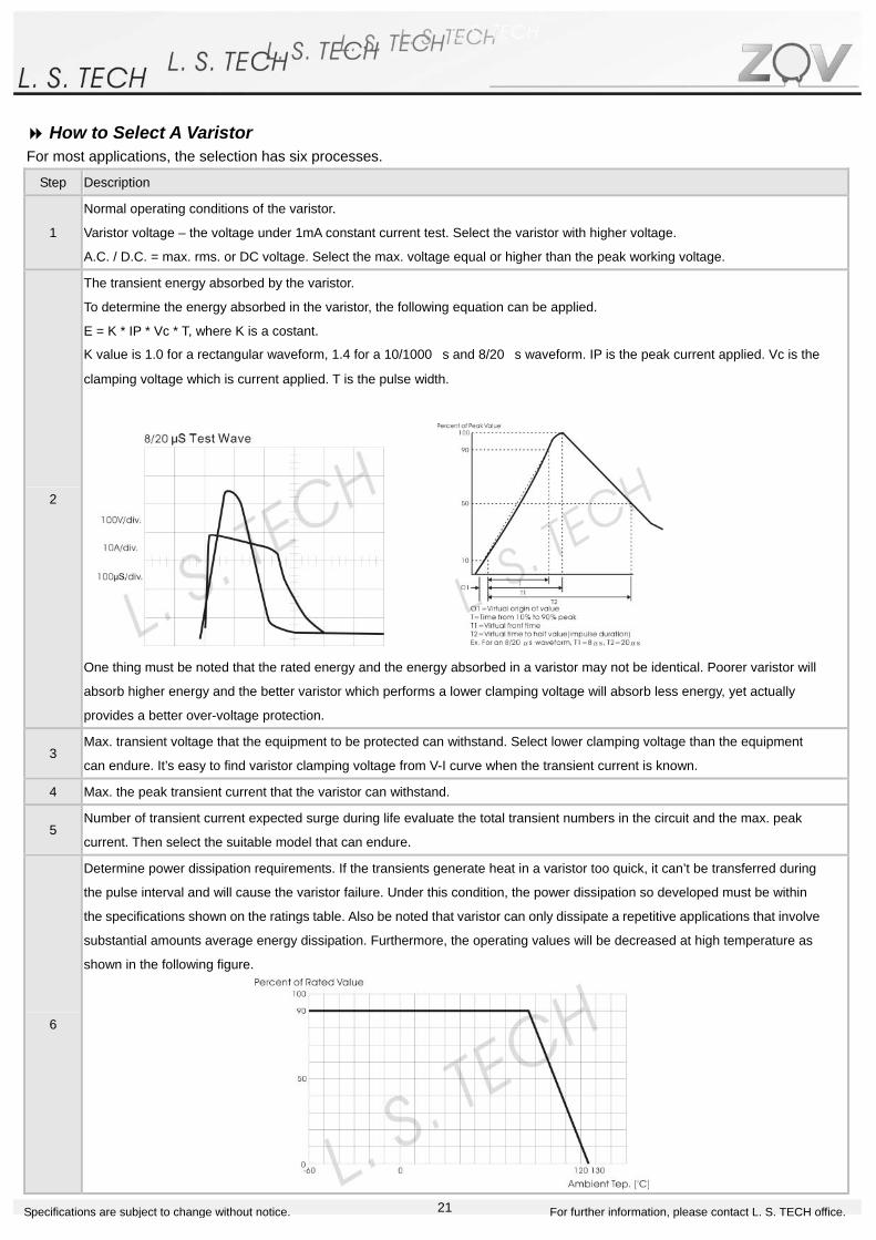
How to Select A Varistor For most applications, the selection has six processes.
Step Description
1
Normal operating conditions of the varistor.
Varistor voltage – the voltage under 1mA constant current test. Select the varistor with higher voltage.
A.C. / D.C. = max. rms. or DC voltage. Select the max. voltage equal or higher than the peak working voltage.
2
The transient energy absorbed by the varistor.
To determine the energy absorbed in the varistor, the following equation can be applied.
E = K * IP * Vc * T, where K is a costant.
K value is 1.0 for a rectangular waveform, 1.4 for a 10/1000 μs and 8/20 μs waveform. IP is the peak current applied. Vc is the
clamping voltage which is current applied. T is the pulse width.
One thing must be noted that the rated energy and the energy absorbed in a varistor may not be identical. Poorer varistor will
absorb higher energy and the better varistor which performs a lower clamping voltage will absorb less energy, yet actually
provides a better over-voltage protection.
3 Max. transient voltage that the equipment to be protected can withstand. Select lower clamping voltage than the equipment
can endure. It’s easy to find varistor clamping voltage from V-I curve when the transient current is known.
4 Max. the peak transient current that the varistor can withstand.
5 Number of transient current expected surge during life evaluate the total transient numbers in the circuit and the max. peak
current. Then select the suitable model that can endure.
6
Determine power dissipation requirements. If the transients generate heat in a varistor too quick, it can’t be transferred during
the pulse interval and will cause the varistor failure. Under this condition, the power dissipation so developed must be within
the specifications shown on the ratings table. Also be noted that varistor can only dissipate a repetitive applications that involve
substantial amounts average energy dissipation. Furthermore, the operating values will be decreased at high temperature as
shown in the following figure.