Embed Size (px)
Citation preview

Islamic Republic of Iran
Vice Presidency for Strategic Planning and Supervision
General Technical Specification and Execution Procedures for Transmission
and Subtransmission Networks Shunt Reactors at HV Substations
NO: 483-1
Energy Ministry - Tavanir Co.Power Industry Technical Criteria Project www.tavanir.ir
Office of Deputy for Strategic Supervision Bureau of Technical Execution Systemhttp://tec.mporg.ir

CONNTENTS Description PAGE
1- General Requirements.......................................................................................................... 3
2- Design and Construction ..................................................................................................... 4
2-1- Magnetic circuits and cores .................................................................................... 4
2-2- Windings ................................................................................................................ 5
2-3- Oil .......................................................................................................................... 6
2-4- Tank ....................................................................................................................... 6
2-5- Painting .................................................................................................................. 7
2-6- Penalties and cost evaluation ................................................................................. 8
2-7- High voltage terminals ........................................................................................... 8
2-8- Cable boxes and cubicle wiring ............................................................................. 8
2-9- Wheels .................................................................................................................... 9
2-10- Conservator .......................................................................................................... 9
2-11- Valves ................................................................................................................ 10
2-12- Cooling system ................................................................................................... 10
2-12-1- Natural cooling system ............................................................................. 10
2-12-2- Forced- air- cooling system ...................................................................... 11
2-12-3- Forced- oil forced- oil cooling system ..................................................... 11
2-13-Temperature indicating devices .......................................................................... 12
2-14- Protective relays ................................................................................................. 13
2-14-1- Buchholtz relay ........................................................................................ 13
2-14-2- Thermal relay ........................................................................................... 13
2-15- Packing and shipping ......................................................................................... 13
2-16- Maintenance equipments .................................................................................... 14
2-17- Rejection ............................................................................................................ 14
3- Rating plates ...................................................................................................................... 14
4- Spare Parts and Tools ........................................................................................................ 15
5- Tests .................................................................................................................................. 16
5-1- Routine tests ......................................................................................................... 16
5-2- Type tests ............................................................................................................. 16
5-3- Special tests .......................................................................................................... 16
6- Drawings & Documents .................................................................................................... 17
6-1- Documents to be given by tendered ..................................................................... 17
6-2- Documents to be given by contractor / supplier ................................................... 17
7- Transportation, storage, Installation and Commissioning ................................................. 18
7-1- Inspection and reception ...................................................................................... 18
7-2- Handling ............................................................................................................... 19
7-3- Storage ................................................................................................................. 20
7-4- Installation of reactor ........................................................................................... 20
7-5- Oil filling .............................................................................................................. 21
7-5-1- Preparation ................................................................................................. 21
7-5-2- Vacuum treatment ...................................................................................... 22
7-5-3- Vacuum filling ........................................................................................... 23
7-5-4- Commissioning tests .................................................................................. 23

General Requirements
1
TECHNICAL SPECIFICATION OF SHUNT REACTORS

Technical Specification Of Shunt Reactors
2

General Requirements
3
1- General Requirements This specification covers the requirements for design, manufacture, factory testing, marking, packing, transportation, installation and commissioning of shunt reactors and accessories. Reactor shall be designed, manufactured and tested according to the requirements of the following standards and with requirements of this specification: IEC 60289: Reactors IEC 60044: Bushing transformers IEC 60137: Bushings ANSI C57-21: Shunt reactors. IEC 60076-1: Power transformers - General. I EC 60076-2: Power transformers -Temperature rise. IEC 60076-3: Power transformers - Insulation levels, dielectric tests and external clearances
in air. IEC 60076-3: Guide to lightning impulse and switching impulse testing of power
transformers and reactors. IEC 60076-5: Power transformers - Ability to withstand short circuit. IEC 60076-8: Power transformers – User guide. IEC 60076-10: Power transformers - Determination of sound levels. ISO 1461: Metallic - coating, hot dip galvanized coating on fabricated ferrous products
requirements BS 4504: Flanges and bolting for pipes valve & fittings. All amendments, supplements and reference publications listed in the following standards. The reactor shall be designed and manufactured to facilitate operation, inspection, cleaning and repairs. All apparatus shall also be designed to ensure satisfactory operation under the atmospheric conditions prevails at the site (s) and under such sudden variation of load and voltage as may be met with the working conditions on the system. All Materials used shall be new and of the best quality and of the class most suitable for working under the conditions specified and shall withstand the variations of atmospheric temperature and conditions arising under working conditions without deterioration or the setting up of undue stressed in any part, and also without affecting the strength and suitability of the various parts for the work which they have to perform. The design and manufacture of the reactor and auxiliary plant shall be such that the noise level is a minimum and that the level of vibration does not diversely affect any clamping or produce excessive stress in any material. The reactor shall be designed with particular attention to the suppression of harmonic currents, especially the third and fifth. The reactor shall be designed to ensure that leakage flux does not cause overheating in any part of the reactor. The reactor shall deliver its full rated capacity under the specified condition prevailing at site.
Technical Specification Of Shunt Reactors
4
All current carrying components such as bushings and connectors shall have a minimum load carrying capacity equal to 120% of that of the associated windings under all service conditions. All oil pipe flanges shall be to BS 4504 as regards both dimensions and drilling, unless otherwise approved, cast iron shall be used for chambers of oil filled apparatus or for any part of the equipment which is in tension of subject to impact stresses. Where made of steel or malleable iron, operating boxes, rods, radiations, tubes and other fittings for outdoor equipment shall be galvanized according to ISO 1461. The reactor shall be capable of withstanding the thermal and mechanical effect of short circuit. All contactors or relay coils and other parts shall be suitably protected against corrosion. Where frameworks are of the box type and are used for housing secondary wiring and connections provision shall be made for fitting suitable low temperature heaters. All apparatus shall be designed to obviate the risk of accidental short circuit due to animals, birds and rodents. All DC equipment shall be suitable for operation at the normal DC voltage specified and shall operate satisfactorily between ± 10 percent of that voltage. The reactor shall be capable of satisfactory operation at maximum voltage without exceeding the guaranteed temperature rise. Knee point of the saturation curve shall occur at not less than 125 percent of the rated voltage. Bushing shall satisfy all requirements of IEC standards 60137 and 60233. The oil used in reactor shall be refined mineral oil, and shall be in accordance with requirements and specifications of IEC 60296. Bushing current transformers shall satisfy the requirements of standard IEC 60044.
2. Design and Construction
2.1. Magnetic circuits and cores
The core of the reactor shall be constructed from highest quality, non- aging, cold rolled grain- oriented silicon steel especially suitable for the purpose. The steel shall be in thin laminations, and after cutting to suitable sizes, rolled to insure smooth surfaces at the edges. Both side of each sheet shall have an insulated surface treatment or coating providing the required resistance.

Design and Construction
5
The cores, framework, clamping arrangements and structure of the reactor shall be capable of withstanding any shocks to which they may be subjected during transport, installation and service. Adequate provision shall be made to prevent movement of internal parts of reactor relative to the tank, to support the core structure in the tank and to carry the weight of the core and windings when suspended. The core and coil assembly shall be provided with suitable lugs for the purposes of lifting of the entire assembly. Earthquake considerations shall satisfy the requirements of IEEE 693. The resonant frequency shall be accurately calculated to avoid mechanical resonances. Reactor magnetization curve shall be provided for all operation conditions.
2.2. Windings
Coils shall be constructed to avoid abrasion of the insulation, allowing for the expansion and contraction set up by changes of temperature or the vibration encountered during normal operation. The windings and connections shall be braced to withstand shocks which may occur during transport or due to switching or other transient conditions during service. Winding conductors shall be free from scale, burrs and splinters and shall have rounded corners and, shall be uniformly insulated. All conductors used for the coil structures shall be made by copper. The conductors shall be transposed at sufficient intervals in order to minimize eddy current and equalize the distribution of currents and temperature along the windings. If flat wire is used, there is no need for transposing the winding and this action is not for reduction of eddy currents, and only is used to make the length of winding equal. The neutral point of the star windings shall be brought out via a suitable bushing and shall not be connected to the inside part of the tank. For 400kV reactors, the neutral bushing shall be selected according to Um=145 kV. Winding insulation shall be of uniform or non-uniform quality and composition, which shall provide good insulation, minimum wrapage, resistance to deterioration in hot oil, and adequate mechanical and dielectric strength for the service required. Varnishes and insulating compounds, when used, shall be of a type impervious to hot oil. Varnish application on coil windings may be given only for mechanical protection and not for improvement of dielectric properties. Materials used in the insulation and assembly of the windings shall be insoluble, non-catalytic, and chemically inactive in the hot reactor oil under the operating conditions. Each assembled core and coils shall be dried in vacuum at not more than 0.5 mm of mercury and shall be impregnated with oil immediately thereafter to ensure proper moisture and air elimination within the insulating structure. All metal parts of the reactor with the exception of the individual core laminations, core bolts and associated individual side plates shall be maintained at some fixed potential. The core stack shall be earthed internally through grounding link, located on the top of the core.
Technical Specification Of Shunt Reactors
6
2.3. Oil
The oil shall comply with the requirements of IEC 60296 and shall be suitable in all respects for use in the equipments when operated under the conditions laid down in this specification. It shall be pure mineral oil obtained form optimum refinement by proven process form high quality naphtenic base crude. It shall be free from moisture, acid, alkali, sulfured and other corrosive compounds and shall be free form additives of any type, either natural or synthetic. Bidder shall submit the commercial name and specification of oil proposed. The offered oil shall be suitable for mixing with oils of similar specifications form other manufacturers without affecting the guaranteed characteristics. It shall not form a deposit under Max. allowable normal operating temperature. The oil shall meet the requirements of IEC 60296 at the destination point. The purchaser may draw samples, in accordance with ASTM sampling methods, of the delivered oil for testing to determine compliance with these requirements. The transformer oil shall be delivered in filled drums, the drums, the drums shall contain 200 liters. The drums shall be new of top quality and general of the type normally used in the oil branch. Externally they shall be treated against corrosion and painted with oil and weather-resisting paint.
2.4. Tank
The reactor tank shall be a hot- rolled low carbon steel plate. The thickness of laminations shall be so to satisfy tolerable deflection. Reactor tanks shall be so designed to be lifted by crane and transported without overstraining any joints and without causing subsequent leakage of oil. Each tank shall be provided with a minimum of four jacking plate at the same level to enable the reactor, complete with all tank mounted accessories and filled with oil, to be raised or hauled and slewed in any direction. The base of each tank shall be so designed that it will be possible to move the complete reactor in any direction without injury when using roller plates or rails. Inspection openings man-holes shall be provided of ample size to give easy access to build-in C.T's. terminals lower ends of bushings and for testing the earth connections. Each reactor shall be provide with two external ground pads (on opposite sides) each with two tapped holes for connection to earth wire. Each reactor shall be sealed such that it will be oil-tight. The gaskets shall be made of a resilient material and not chemically affected by oil, which will not deteriorate under the action of hot oil and will remain oil tight, washers holler shall be so designed to prevent excessive stress on washers.
Design and Construction
7
A pressure relief device shall be provided of sufficient size for the rapid release of any pressure that may be generated within the tank to prevent explosion. It shall be capable of maintaining the oil tightness of the reactor under all conditions of normal service. The device shall operated at a static pressure of less than the hydraulic test pressure for reactor tanks and shall be provided with a device visible from ground to indicate operation. The pressure relief device shall be equipped with Trip/Alarm contacts. Unless otherwise approved, the relief devices shall be mounted on the main tank. If a diaphragm is used it shall be of approved design and material. The pressure relief device should be installed on top of the tank in order to be far from the high voltage equipments. Approved terminals shall be provided at the base of the tank for earthing purposes.
2.5. Painting
All grease and oil deposits shall be removed and all surfaces to be painted shall be clean and dry, free form moisture at the time of painting. All painting shall be carried out under suitable atmospheric and conditions in accordance with the paint manufacturers recommendations. Paint coating shall be uniform and free from defects. Primers and pre-treatment shall be applied as soon as practicable after surface has been cleaned. For multicoated application, the individual coats shall be tinted such as to give distinct and easily visible color difference between coats to facilitate inspection. Area adjacent to field welds shall be left unpainted for a distance of five centimeters. All steel workpants supporting steelwork and metalwork, except galvanized surfaces or where otherwise specified, shall be shot blasted to BS 4232. All surfaces shall then be painted with one coat of epoxy zinc rich primer, two pack type, to a film thickness of 50 microns, this primer shall be applied preferably by airless spray and within twenty minutes but not exceeding one hour of shot basting. Painting on case iron and steel plates, cabinets shall consist of four at least 40 mm coatings containing one primary, two coat of non glossy oil, one final weather resistant coat with a total minimum thickness of 160µm. The interior of the control cabinet and other cabinets shall be painted with three coats, of which the final coat shall be anti-condensation finish. Galvanized surfaces shall not be painted in the works. After erection at site, the surface shall be thoroughly examined, and any deteriorated of such shall be made good.
Technical Specification Of Shunt Reactors
8
2.6. Penalties and cost evaluation
In tender comparison, the capitalized value of the guaranteed losses will be taken into account and be taken into account and be added to the tender prices. The losses will be capitalized at the rate specified in schedules. In case of measured loss is higher than the guaranteed value one of the following will govern:
- If extra losses are within 10% tolerance indicated, the reactor shall be accepted provided that other technical requirements are fulfilled and seller pay penalty for losses in excess of guaranteed values using the rate specified in schedules.
- If extra losses exceeding 15% tolerance indicated, then the acceptance of the reactor shall be entirely at the decision of the purchaser, if accepted penalty charges shall be born by seller, as described above.
- Continues current, at rated voltage shall not deviate more than the tolerance stated in the latest revision of IEC 60289. Other wise purchaser has the right to reject the reactor. However if the current is in the above mentioned range the seller will pay penalty proportional to the difference between rated power and actual (measured) power.
2.7. High voltage terminals
Terminals shall be of pin type. The terminal shall be designed according to bending moment owing to wind load or earthquake force together with horizontal pull of the high voltage line conductor. Pin type terminals for maximum rated current up to 1600 A shall be designed as a pin of 125 mm length and having 30 ± 0.15 mm diameter. Terminals of copper alloy which is tinned to a thickness of minimum of 50 micro meters. A copper alloy which is sensitive to season cracking shall not be used. Terminals of aluminum or an aluminum alloy shall not be treated.
2.8. Cable boxes and cubicle wiring
Cable boxes shall be suitable for cables entering form below. They shall be weatherproof and be complete with all gaskets. Gland plates shall be insulated from the cable boxes. If metallic glands are used, single core cable glands shall be insulated form the gland plate. Gland plated insulation shall be capable of withstanding a dry high voltage test of 2000 volts a.c. for one minute. Protection degree of cubicles should be IP 54 or IP55. The D.C. and A.C. voltage supplies and wring to main protective gear shall be segregated form those for back-up protection and also form protective apparatus for special purposes. Each such group shall be fed through separate fuses form the bus wires. The screens of screened pairs of multi core cables shall be earthed at one end of the cable only. The position of the earthing connection shall be shown clearly on the diagram.
Design and Construction
9
All wires on panels and all multi core cable shall have ferrules which bear the same panels. Wires with size greater than 2.5mm must have wire shoes. The cabinet shall be of weatherproof and dustproof construction and conduit connections to the terminals cabinets shall be of the threaded type. The cabinets shall be equipped with a hinged door and mounted in an accessible location. Cabinet shall be provided with a door switch, light and one single phase AC convenience outlet complete with suitable MCB. Thermostatically controlled ant condensation heater shall be provided for cabinet. The terminal blocks shall have bases and barriers molded integrally, with brass inserts. The terminal screws shall be the washer type, long enough for connection two conductors to one screw connection. Cabinet shall be provided with 20 percent spare terminals.
2.9. Wheels
Swiveled wheels shall be suitable for use on the standard rail and provided so that they can be turned through an angle of 90. Axial distance between wheels in according to Iran railway standard, shall be 1435mm. Suitable means shall be provided for anchoring of the reactor body to the foundation / or rails after dismantling the wheels of the reactor. In face, after anchoring of the reactor body to the foundation, the wheels shall be removed and the reactor body shall be fixes to the foundation, at least at 6 points, using bolts.
2.10. Conservator
Conservator tank should have adequate capacity for the ambient temperature range specified, but not less than 15% of the reactor oil. The tank shall be mounted with proper slope between the ends to facilitate draining and the lower end shall be fitted with a drain/ filter press valve of suitable size, complete with dummy plugs. The conservator shall be provided with a manhole correctly sized filling valve with dummy plug, and lifting eyes. The connecting pipe to the main reactor tank shall be provided with an indicating shout-off valve located to the conservator side of the gas detector relay. Sealed type conservator is preferred. In this case provision shall be made to give an alarm signal, if the air bag be damaged and oil leaks to the air side of the diaphragm. The air outlet from each conservator vessel shall be connected to dehumidifying breather.
Technical Specification Of Shunt Reactors
10
Oil conservator should be equipped with oil level indicator. Magnetic oil level gauge, which can be read from ground level, should be mounted on the outer end of the conservator tank. Oil level gauge shall contain contacts for alarm. The dial shall indicate the minimum, maximum and normal levels. Alternatively, the conservator shall be sealed expansion tank type provided with a flexible oil resistant air bag. An alarm device shall be provided to give and alarm in the event of rupture of the bag and entering of air into the conservator.
2.11. Valves
Each reactor tank shall be fitted with the following valves: - An oil sampling device at the top and bottom of the main tank. - A valve for connection to the vacuum pump for creating vacuum in the tank. - One valve at the top and one valve at the bottom of the tank, mounted diagonally opposite each other,
for connection to oil circulating and oil filtering equipment. The lower valve shall also function as a drain valve.
- Pressure test and gas sampling valve, either separate or integral with pressure or gas relay. - A one way valve should be provided to prevent oil flow from the conservator to the main tank during
fire or similar accidents. The valve should be open during normal condition and should shut off during abnormal exceeded rate oil flow from the conservator to the tank.
- A valve for draining of oil from each cooling unit (radiator). - A valve for monitoring of the oil of monitoring of the oil of main tank. - A valve for oil injection. All oil valves shall be designed to hold hot insulating oil without leaking.
2.12. Cooling system
2.12.1 Natural cooling system (ONAN) Radiators shall be so designed to be accessible for cleaning, painting, to completely drain oil into the tank when the tank is being drained to thoroughly vent into the tank and to insure against formation of gas pockets when the tank is being filled. Each radiator shall be removable with no need to remove the other. At each radiator connection an indicating shut-off valve which can be locked in either open or closed position shall be provided. Radiator shall have lifting eyes, an air vent at the top and an oil drain at the bottom (both equipped with suitable plugs).
Design and Construction
11
2.12.2. Forced- air- cooling system (ONAF) Each radiator shall be removable with no need to remove the other and for each of them a separately motor shall be provided. Protective equipment shall be provided for the fan motors. Test switches shall be provided for testing each group of fans. The control equipment to be furnished shall be fully automatic, designed to start and stop the two stage fan motors as per the demands of temperature and shall include a magnetic contactor with auxiliary alarm contacts which close with contactor, and any other auxiliaries necessary. Switches shall be provided for automatic/manual control of each fan group. An under voltage relay or equivalent device should be proposed to alarm for failure of each fan or device or subgroup of fans, and/or for the case of power supply loss. Motor protective circuit breakers shall be equipped to at least one set of auxiliary normally closed contacts. Each motor protective circuit breaker shall be equipped with overload and short-circuit protection of such a type and rating that complete selectivity exists, both between these and preceding main fuses or MCB's, Under all load conditions. Bird barriers should be installed on fans. Some alarming devices with normally open contacts shall be procured to show the malfunctions of each unit fans, or cooling radiators set. Alarm devices with normally open contacts, shall be procured for the malfunction of fans or cooling radiators, of each unit. Some contacts should be procured to turn on the alarming lamps, for illustration of operating fans status. Entire requirement for forced-air-cooling of second stage will remain for third stage too, in addition to the fans of third stage. 2.12.3. Forced – air forced- oil cooling system (OFAF) The reactors with first stage of natural and second stage of forced air cooling system are required to be supplemented by the forced-oil cooling equipments, at third stage with following characteristics: Oil circulating pumps shall be driven by directly coupled motors. Indication shall be provided indicating direction of rotation of the pumps. The non-sensitive area (marginal temperature between setting of start each group of cooling and setting of stop) shall be so large as to avoid unnecessarily frequent cooler starts-stops. The non-sensitive area in °c shall be specified by the supplier. For choice of mode of operation (automatic/manual), twist-grip switches shall be provided. Switches shall be two-pole type, one pole to control the relevant motor-protective circuit breaker, and other for the signal circuit. Following alarm initiating devices having normally open contacts shall be provided for fault initiation, as applicable for the method of cooling employed:

Technical Specification Of Shunt Reactors
12
- cooling fan/fans failure for each radiator bank unit cooler - Failure of oil pump - Low oil flow for each pump Following initiating contacts shall be provided to illuminate lamp indicators:
• Cooling fans in action for each stage. • Oil pump in action for individual pumps. • Cooling system on automatic control. • Cooling system on manual control.
2.13. Temperature indicating devices
Winding temperature indicating devices (only on middle phase) shall indicate the temperature of the winding and shall have a load-temperature characteristic approximating to that of the main winding. Two sets of contacts shall be provided for initiation of alarm and trip relays. For reactor having forced cooled ratings, whether the forced cooling is to be supplied initially (or at a later date), additional sets of switch contacts shall be provided to start and stop automatic control of the cooling system. Temperature indicating devices shall incorporate a dial and a pointer indicator and a separate pointer to register the maximum temperature reached. All temperature indicators shall be housed on the side of reactor at eye level and accessible and shall be mounted so that they will not be affected by vibration. Dial type oil temperature indicator with its sensing element located in the path of the hottest oil. The dial shall be mounted on the reactor adjacent to the winding temperature indicator. The temperature indicator shall be equipped with adjustable contacts to perform the following functions: - Contacts for the possibility of automatic control of cooling system - Alarm actuating - Trip actuating
Design and Construction
13
2.14. Protective relays 2.14.1. Buchholtz relay Two element gas detector relay should be provided in the pipe connecting the conservators to main tank. The relay shall be equipped with two sets of contacts, one set to operate an alarm on slow gas accumulation and one set to trip the reactor on surge accumulation. The gas-operated relay shall be provided with test push-button and specified valve equipment for pumping in air for testing the relay function. The supplier shall specify in the "Installation and service instructions" the quantity of air and operating pressure necessary for testing the relay. The gas-operated relay shall be so arranged and designed that its active parts are accessible for inspection, repairs and replacement. A 5 cm dia. Copper pipe shall be connected to the relay test-cock and to a valve located near ground level to facilitate sampling of the gas. A sign must be engraved on Buchholtz relay in order to show correct assembling of the relay.
2.14.2. Thermal relay Each reactor winding shall be provided with one adjustable thermal relay and auxiliary relays (as required). One contact shall close for annunciation when the maximum safe winding temperature for continuous operation has been reached. The second contact shall close at a slightly higher temperature for circuit breaker tripping. All required auxiliary relays shall be mounted in the reactor terminal box. The thermal relays shall be responsive to winding currents as well as oil temperature and shall have thermal characteristics corresponding to those of reactor winding.
2.15. Packing and shipping
The method of packing shall be such as to protect adequately the tank, and those parts contained within and attached, for transportation. Two three axis impact recorders (one mechanical and one digital, or both digital) or shock indicator shall be attached to the reactor near the top of the main tank to record maximum shock acceleration during the whole period of loading, shipment, unloading and transportation. The contractor shall take necessary steps, and shall make sure that the impact recorders function properly during the whole period of transportation from the factory up to its final delivery at the site. Reactor to be transported in dry nitrogen gas shall be filled and maintained by the contractor at a pressure in excess of atmospheric pressure until the gas is replaced by oil. The gas pressure shall be recorded before displacing. Besides, it is necessary to consider an auxiliary gas capsule.
Technical Specification Of Shunt Reactors
14
Means shall be provided for measuring the pressure in the tank. A gas cylinder shall be connected to the reactor through a pressure reducing valve, pressure gauge and non-return valve.
2.16. Maintenance equipment
Special tools Complete sets of any special tools, wrenches or equipment that may be necessary or convenient for assembling, disassembling, and moving the same reactors in substation shall be furnished. Lifting device The manufacturer shall furnish sets of devices, consisting of lifting beam(s) with slings and devices or other secure fastenings for use with a crane for lifting the cores and windings from the cases and for lifting the reactor. Hydraulic Jacks The manufacturer shall furnish sets of manually operated hydraulic jacks of ample capacity and suitable heights for raising the reactor including all necessary tools.
2.17. Rejection
The purchaser reserves the right to reject the reactor and demand a new reactor if during tests or service, any of the following discrepancies in respect of guaranteed values come to light: - Measured losses exceed the guaranteed value by more than the tolerances allowed by IEC
60289. - Measured impedance measured exceeds the guaranteed value by more than the tolerances allowed
by IEC 60289. - Oil or winding temperature rise exceeds the guaranteed values by 5 Deg. Cen. - Reactor fails on impulse tests. - Reactor fails on power frequency withstand test. - If it is proved that the reactor has not been manufactured in accordance with the agreed
specification.
3. Rating plates Each reactor shall be provided with a rating plant of weatherproof material, fitted in a visible position, showing the appropriate items indicated below, According to standard IEC 60289:
Rating Plates
15
- Information to be given in all cases:
- Type of reactor - Outdoor/indoor application. - Applicable standard - Manufacturer's name - Manufacturer's serial number - Year of manufacture - Number of phases - Rated power - Rated frequency - Maximum operating voltage - Insulation level (s). - Winding connection - Reactance at rated voltage (measured value) - Type of cooling - Total mass - Mass of insulation oil
- Additional information to be given in certain cases
- Temperature rise (if not a normal value) - Transportation mass (for reactors exceeding 5 t total mass) - Type of insulating liquid, (if not mineral oil). - Details regarding tapping, if any - Zero- sequence reactance. - Mutual reactance
4. Spare Parts and Tools The manufacturer's recommended spare parts for 5 years trouble free operation and any special tools deemed necessary for erection, maintenance and repair shall be provided.
Technical Specification Of Shunt Reactors
16
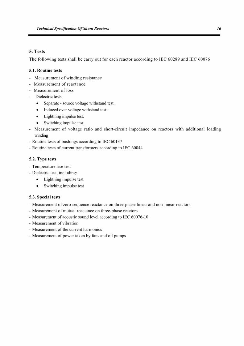
5. Tests The following tests shall be carry out for each reactor according to IEC 60289 and IEC 60076
5.1. Routine tests
- Measurement of winding resistance - Measurement of reactance - Measurement of loss - Dielectric tests:
• Separate - source voltage withstand test. • Induced over voltage withstand test. • Lightning impulse test. • Switching impulse test.
- Measurement of voltage ratio and short-circuit impedance on reactors with additional loading winding
- Routine tests of bushings according to IEC 60137 - Routine tests of current transformers according to IEC 60044
5.2. Type tests
- Temperature rise test - Dielectric test, including:
• Lightning impulse test • Switching impulse test
5.3. Special tests
- Measurement of zero-sequence reactance on three-phase linear and non-linear reactors - Measurement of mutual reactance on three-phase reactors - Measurement of acoustic sound level according to IEC 60076-10 - Measurement of vibration - Measurement of the current harmonics - Measurement of power taken by fans and oil pumps

Tests 17
- Measurement of magnetic characteristic - Measurement of "tangent delta" (tgδ) and capacitance Engineer shall have access to the works for determination or assessment of compliance with the prevision at this specification or to witness the contractor's inspection or tests. A certificate of compliance of the equipment with the design, routine and type tests stipulated in the applicable standards shall be produces by the contractor. Owner reserves the right to have representative present during final shop and functional testing. The contractor shall advise the date of test at least sixty (60) in advance.
6. Drawings & Documents
6.1. Documents to be given by tendered
- Filled schedule reactor (II) - Catalogue & technical pamphlets - Summary of type test reports - Outline drawing - Detailed summary of exceptions to tender specifications - Reference list - List of special tools - List of spare parts
6.2. Documents to be given by contractor /supplier
The electrical and mechanical design, fabrication, factory testing, working and packing, transportation, erection, site test, operation and maintenance drawings, documents and manuals shall be submitted not limited to the following: - Calculation sheets to establish adequacy of reactor in any respect. - Overall dimensions of the assembled reactor. - Location and outlines of all bushings and terminal boxes. - Details of all lifting equipment. - Location and dimensions of manholes and inlet and outlet valves. - Location and size of sampling devices. - Proposed location, dimensions and details of cooling equipment.

Technical Specification Of Shunt Reactors
18
- Location of tank grounding provisions. - Drawings that indicating the open or close statures of the all valves, at three conditions: transportations,
after vacuum and during operation. - Drawings for internal and sectional view of active part and winding - Proposed location, dimensions and details of oil preservation equipment. - Control and wiring diagrams. - Details of miscellaneous devices such as relays, oil level indicators, piping and relief diaphragm. - Assembly drawing. - Mounting details. - Name plate drawings. - Packing details. - Routine test certificates - Site test instruction manuals. - Shipping, warehousing, assembly, erection, commissioning, operating and maintenance
instruction manuals. - Type test documents. - Loading on foundation. - Magnetization curve. - List of components - Work schedules and monthly progress report - Drawing list - Final as built DOC./Dwg - Dismantling, reassembling and adjusting manuals
7. Transportation, Storage, Installation and Commissioning
It is essential that the transport, storage, installation and commissioning of reactor be performed in accordance with instructions given by the manufacturer.
7.1. Inspection and Reception
A thorough external inspection should be made before the unit is removed from the vehicle. If there is evidence of damage in transit, an inspector representing the carder and the manufacturer should be notified. In all cases, the manufacturer's instructions should be followed. For shipments equipped with impact recorders, representatives from the purchaser and carrier should be present to inspect the reactor and examine the impact recorder chart at the site location.

Transportation, Storage, Installation and Commissioning 19
For gas filled shipments, upon arrival at the site, check the gas pressure in the tank and in the supply cylinder if one is provided. The gas pressure should remain positive even in the coldest weather. If the gas pressure is zero, there is a possibility that outside air and moisture may have entered the tank and manufacturer should be notified. Check the oxygen content and dew point of the gas in the tank. It may be safely assumed that the reactor has not been contaminated in transit with outside air or moisture, if the dew point of the gas indicates a relative humidity of less than 1% and the oxygen content is below 1% (if shipped in nitrogen) and more than 10% (if shipped in dry air). If the oxygen content and dew points are outside these values, drying may be necessary and the manufacturer should be notified. An internal inspection shall be made of the reactor if external inspections or impact recorder indicates possible shipping damage. Dry air should be continuously supplied into the reactor while the manhole cover is removed. Extreme care must be taken that the oxygen content is 19.5% or more whenever anyone is inside. Dew point should be kept as close as possible to the value as measured at the factory. The reactor should not be left open any longer than necessary preferably less than 2 h. When the internal inspection is made, the manufacturer's recommendations should be followed. Inspection will include, for example, removal of any shipping blocking; examination for indication of core shifting; test for unintentional core grounds; visual inspection of windings, leads, connections including clamping, bracing, and blocking; inspection of internal current transformers, etc. If any internal damage that may have been due to rough handling handing is found during this inspection, the carrier and the manufacturer should be notified. The manufacturer should also be notified if any foreign material is discovered. The reactor should not be opened under circumstances permit the entrance of moisture(such as on days of high humidity).
7.2. Handling
The Reactor should always be handled in the normal upright position unless information from the manufacturer indicates it can be handled otherwise. Where a reactor cannot be handled by a crane or moved on wheels, it may be skidded or moved on rollers or slip plates, depending upon compatibility of reactor base design and the type of surface over which it is to be moved. Lifting lugs and eyes are normally provided for lifting the complete reactor, and the necessary additional means are provided for lifting the various parts assembly. The lifting lugs and eyes are designed for vertical lift only. When lifting the complete reactor or a heavy piece, the cable should be so attached to provide a vertical force to each lug. Use Lifting cables of appropriate lengths so that the reactor will be lifted evenly. Jack bosses or pads on all reactors are provided so that it can be raise by means of jacks. On some reactors, jacks may be placed under the reactor bottom plate at points designated by the manufacturer. The drawings or manufacturers instructions should be consulted.

Technical Specification Of Shunt Reactors
20
7.3. Storage
If the reactor will not be installed after reception or will be stored for a long time, the storage shall be done according to the following requirements:
- The storage process shall be in accordance with manufacturer instructions. - If the reactor has been shipped without oil, it shall be filled with oil before storage. - The conservator and silica gel breather should be installed on reactor. - The electric panels witch equipped with heater, shall be supplied with an appropriate power
supply. - Bushings shall be stored in a covered condition in their original packs. - The radiators can be stored in even covered or uncovered area while in any case; the flanges shall
be protected against moisture.
7.4. Installation of reactor
Reactor installation shall be in accordance with manufacturers instructions. In this section, it is given the seeps of installation, for an oil reactor, as an example: - Putting of the reactor from temporary location on the foundation. - Regulation of the reactor and fixing the bolts between foundation and the reactor - Installation of reactor marshalling box. - Installation of radiator and performing required clamping, if the radiator installed on the reactor. - Installation of oil pump and auxiliaries (if exist). - Installation of fan pump and auxiliaries (if exist). - Installation of reactor oil tank, consist of corresponding piles, required pipe connections and relays,
including: buchholtz relay, all valves and auxiliaries. - Installation of pile under bushing , with or without bushing current transformer - Installation of rest connecting pipes between various parts of reactor, Bolts and required piles. - Installation of bushing and auxiliaries, completely. - Installation of neutral bushing, all auxiliaries and required connections. - Installation of pressure relief. - Refinement and injection of oil. - Cabling and wiring.
Transportation, Storage, Installation and Commissioning 21
- Installation of thermostat and thermometers, including thermal indicators switch. - Installation of fire fighting system. - Installation of air bag within the condenser. - Fixing to the foundation, using bolts (instead of wheels). The foundation shall be capable to carry the complete reactor weight plus 10% safety margin. The reactors equipped with wheels shall be tight to the foundation preventing any movement. The foundation shall be horizontally balanced. Use appropriate means such as interface plates delivered by the reactor to lead the produced gas in the reactor to the gas relay. An oil pit shall be provided beneath the reactor used for drain oil. This pit may be also control the distribution of fire in case of reactor failure. The volume of this pit shall be sized such that it can contain all the reactor oil or using a piping system to deliver the oil to other locations. Foundation height is depend on the carrier vehicle if the reactor is transport with a carriage or deep load truck, the foundation height shall be equal to the carrier vehicle height. In case of large power reactors, the foundation rails shall be long enough to reach the exchange point and levelized with it. If the reactor is handled by a crane, the foundation height is not very important but should be done for providing enough space above and sides of the foundation for crane maneuver. Radiators, liquid piping, valves, and fittings should be thoroughly cleaned and flushed (if contaminated) with clean, warm 25-35°C dielectric liquid before fitted to the reactor. Radiators are usually capable of withstanding full vacuum. If not, these should not be installed until after the tank has been filled with dielectric liquid under vacuum. Liquid – level gauge, temperature gauges, and other accessories should be installed in accordance with manufacturer's instructions.
7.5. Oil Filling
7.5.1. Preparation
Leave the pressure relief device blanked off until after the final vacuum filling, unless the manufacturers instructions indicate the device can withstand full vacuum. If separate liquid expansion tanks or other devices that will not withstand full vacuum are provided, these should be isolated from the main tank before drawing vacuum.

Technical Specification Of Shunt Reactors
22
After all parts have been assembled, the tank should be sealed and pressure tested to ensure that all joints are tight. Some manufacturers also recommend using a vacuum test to determine that the pressure rise with the tank sealed does not exceed manufacturer's recommendations. Check all gasket joints with a suitable leak detector. The tank should hold the gas pressure for at least 4 h without leakage. All leaks detected in the above manner must be eliminated before starting the vacuum filling. Any air leakage into the reactor tank, while a vacuum is being drawn on the reactor, may seriously contaminate the reactor insulation. Ensuring that all leaks have been eliminated, drain the liquid and proceed with the vacuum treatment. The liquid may be drained as quickly as desired, but a rapid rate may create a partial vacuum within the tank. The drain valve should be closed immediately after the tank is empty to prevent entrance of air through the drain connection. Because unforeseen delays may occur before the vacuum treatment is applied, it is recommended that the dielectric liquid be replaced with dry gas during the draining process. After the liquid drain valve is closed, continue to admit dry gas (nitrogen) until a positive gauge pressure exists in the tank.
7.5.2. Vacuum treatment
The principal function of vacuum is to remove trapped air and moisture from the insulation and enable the insulation to attain its full dielectric strength. Small gas bubbles have much lower dielectric strength than the dielectric liquid and may, if located at a point of high stress, lead to failure. By removing most of the gas from the reactor and from the liquid by vacuum filling, the hazard of the small bubbles of free unsolved gas that remain in the windings and insulation is greatly reduced. The degree of vacuum required depends on the design of the windings and insulation and should be determined in consultation between the manufacture and purchaser before assembly is begun. An additional benefit gained from the treatment at high vacuum is that the moisture introduced into the reactor insulation during assembly can be removed before the reactor is energized. A vacuum pump of evacuating the tank to the required degree of vacuum in approximately 2-3 h is recommended. Connect the vacuum pump to the vacuum fill connection on top of the reactor with pipe or reinforced house of sufficient size to minimize line losses. In order to obtain an accurate vacuum value, it is essential that connection of the gauge or manometer be as close to the tank as possible and preferably at a different location on the tank than the vacuum hose. Start the vacuum pump and continue pumping until the tank pressure is constant. Close the vacuum pump valve and check for leaks in the tank or piping. If all joints are tight, there should be no appreciable increase in residual pressure in a period of 30 min.
Transportation, Storage, Installation and Commissioning 23
7.5.3. Vacuum filling
After attaining the required vacuum and holding for 4 h or more, depending on manufacturers instructions, filling may begin (fluid inlet and vacuum connections should be separated as far as possible to keep liquid spray from entering the vacuum pump). The liquid line should be connected to the upper filter press connection or other suitable connection on top of the tank. The processed liquid is admitted through this connection, the rate of flow being regulated by a valve at the tank to maintain a positive liquid pressure external to the tank at all times and to maintain the vacuum at or near its original value. An oil temperature between 60 to 80°C is recommended. The filling rate should not exceed 1.25 cm/min. Filling should be done in one continuous operation, at least to a point above the core and coils. The assembled reactor should not be energized for at least 12 h to allow the insulating oil to absorb residual gas and thoroughly impregnate the insulation.
7.5.4. Commissioning tests
After the reactor has been assembled and filled with dielectric liquid, tests should be made and the test reports preserved to ensure that the reactor is ready for service and to provide a basis for comparison with future maintenance tests. The following tests are suggested (All or any portion of these tests may be made, depending on the equipment available and the importance of the particular reactor): - Insulation resistance test on each winding to ground and between windings. - Insulation power factor or dissipation factor test on each winding to ground and between windings.
Core insulation should also be tested. - Power factor or dissipation factor test on all bushings equipped with a power factor tap or capacitance
tap. - Check winding resistance of all windings with a Kelvin bridge or another suitable test device and
compare with factory test results. - Check operation of liquid and winding temperature indicating devices and their control accessories. - Check dissolved gas, dielectric strength, power factor, interfacial tension, neutralization number, and
water contact of the dielectric liquid. - Check oxygen content and total combustible gas content of nitrogen gas cushion in sealed tank
reactors. A total combustible gas test, where applicable, and a dissolved gas in oil test of the dielectric fluid should also be made soon after the reactor is in service at operating temperature to provide a suitable reference "bench mark".
- Check operation of auxiliary equipment, such as liquid – circulating pumps, fans, etc. in accordance with manufacturer's instructions.
- Check resistance, ratio, and polarity of instrument transformers when provided. These tests should be made from terminal blocks from the control cabinet.
- Bushings tests. - Insulation resistance test on auxiliary and control circuits. - Check operation and wiring of auxiliary and control panels.

Technical Specification Of Shunt Reactors
24
- Check operation of buchholtz relay. - Check the position of the conservator and silica gel breather. - Check the secondary of bushing current transformers and be sure to short circuiting the cores which
will be not used. - Check the neutral connection, piping, fire protection system (if any) and oil leakage if any.

Tables
25
SCHEDULE REACTOR (I) RATING AND CHRACTERISTICS OF SHUNT REACTOR
ITEM DESCRIPTION TECHNICAL PARTICULARS
1 Particulars of system
1-1 Highest system voltage kV 420/245
1-2 Nominal system frequency Hz 50
1-3 Number of phases 3
1-4 Reactor connection manner To bus bar/ to line/ to tertiary winding of transformer
1-5 System neutral earthing Solidly earthed/ Neutral reactor earthed
1-6 Max. duration of short time current sec 1,3
2 Service condition
2-1 Max. Ambient temperature °C 40/45/50/55
2-2 Min. Ambient temperature °C -40/-35/-30/-25
2-3 Altitude above sea level m 1000/1500/2000/2500
2-4 Pollution level Low/medium/high/ very high/special
2-5 Max. wind velocity m/s 30/40/50
2-6 Wind velocity at ice condition m/s 20
2-7 Ice coating thickness mm 5/10/20/25
2-8 Seismic acceleration m/s2 0.2g/0.25g/0.3g/0.35g
2-9 Relative humidity % 90/95/more than 95
2.10 Average value of daily temperature °C *
2.11 Solar radiation w/m2 *
2-12 System short circuit level MVA *
3 Oil type reactor characteristic
3-1 Class (outdoor/ indoor) outdoor
3-2 Type of cooling system ONAN/ONAF/OFAF
3-3 Oil type *
3.4 Nominal voltage kV 400/230
3.5 Nominal power MVAR * 3.6 Type of reactor (three phase /single phase) Three phase
Technical Specification Of Shunt Reactors
26
SCHEDULE REACTOR (I)
RATING AND CHRACTERISTICS OF SHUNT REACTOR
ITEM DESCRIPTION TECHNICAL PARTICULARS
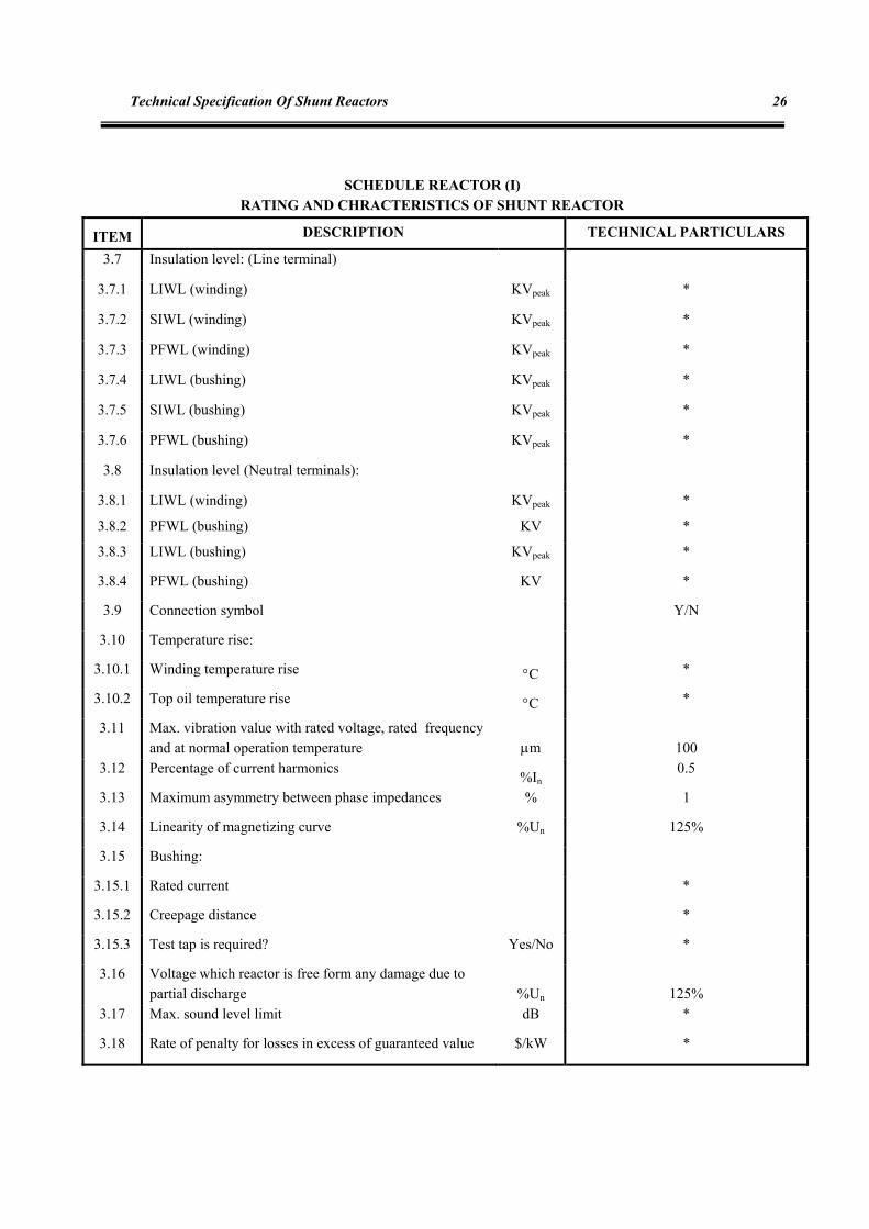
3.7 Insulation level: (Line terminal)
3.7.1 LIWL (winding) KVpeak *
3.7.2 SIWL (winding) KVpeak *
3.7.3 PFWL (winding) KVpeak *
3.7.4 LIWL (bushing) KVpeak *
3.7.5 SIWL (bushing) KVpeak *
3.7.6 PFWL (bushing) KVpeak *
3.8 Insulation level (Neutral terminals):
3.8.1 LIWL (winding) KVpeak *
3.8.2 PFWL (bushing) KV *
3.8.3 LIWL (bushing) KVpeak *
3.8.4 PFWL (bushing) KV *
3.9 Connection symbol Y/N
3.10 Temperature rise:
3.10.1 Winding temperature rise °C *
3.10.2 Top oil temperature rise °C *
3.11 Max. vibration value with rated voltage, rated frequency and at normal operation temperature µm 100
3.12 Percentage of current harmonics %In 0.5
3.13 Maximum asymmetry between phase impedances % 1
3.14 Linearity of magnetizing curve %Un 125%
3.15 Bushing:
3.15.1 Rated current *
3.15.2 Creepage distance *
3.15.3 Test tap is required? Yes/No *
3.16 Voltage which reactor is free form any damage due to partial discharge %Un 125%
3.17 Max. sound level limit dB *
3.18 Rate of penalty for losses in excess of guaranteed value $/kW *
Tables
27
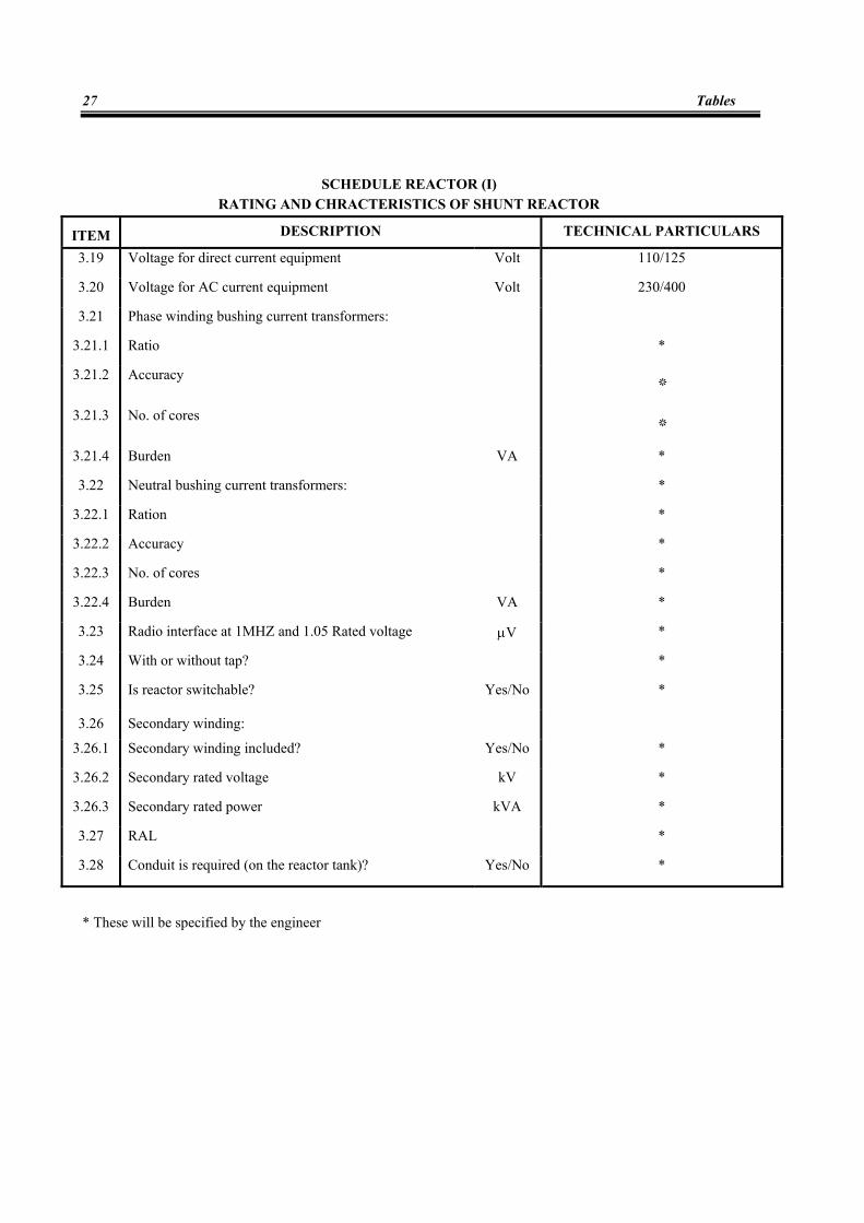
SCHEDULE REACTOR (I)
RATING AND CHRACTERISTICS OF SHUNT REACTOR
ITEM DESCRIPTION TECHNICAL PARTICULARS
3.19 Voltage for direct current equipment Volt 110/125
3.20 Voltage for AC current equipment Volt 230/400
3.21 Phase winding bushing current transformers:
3.21.1 Ratio *
3.21.2 Accuracy *
3.21.3 No. of cores *
3.21.4 Burden VA *
3.22 Neutral bushing current transformers: *
3.22.1 Ration *
3.22.2 Accuracy *
3.22.3 No. of cores *
3.22.4 Burden VA *
3.23 Radio interface at 1MHZ and 1.05 Rated voltage µV *
3.24 With or without tap? *
3.25 Is reactor switchable? Yes/No *
3.26 Secondary winding:
3.26.1 Secondary winding included? Yes/No *
3.26.2 Secondary rated voltage kV *
3.26.3 Secondary rated power kVA *
3.27 RAL *
3.28 Conduit is required (on the reactor tank)? Yes/No *
* These will be specified by the engineer

Technical Specification Of Shunt Reactors
28
SCHEDULE REACTOR (II) RATING AND CHRACTERISTICS OF SHUNT REACTOR
(TO BE SUPPLIED WITH TENDER)
ITEM DESCRIPTION TECHNICAL PARTICULARS
1 General
1.1 Manufacturer's name and country
1.2 Manufacturer's type & designation
1.3 Class (outdoor/ indoor)
1.4 Applicable standard
1.5 Applicable site & ambient condition:
1.5.1 Max. design ambient temperature °C
1.5.2 Min. design ambient temperature °C
1.5.3 Design altitude above sea level m
1.5.4 Pollution level
1.5.5 Max. permissible ice thickness mm
1.5.6 Design seismic acceleration m/s2
1.5.7 Max. permissible velocity m/s
1.6 Documents (test reports/outline /drawings/catalogues/ maintenance & installation manuals /instruction manuals/ references/ list of spare parts)
2 Rated values & characteristics
2.1 Rated power MVAR
2.2 Cooling method
2.3 Rated voltage kV
2.4 Maximum rated voltage kV
2.5 Rated frequency HZ
2.6 Oil specifications:
2.6.1 Oil type
2.6.2 manufacturer
2.6.3 Breakdown voltage kV

Tables
29
SCHEDULE REACTOR (II) RATING AND CHRACTERISTICS OF SHUNT REACTOR
(TO BE SUPPLIED WITH TENDER)
ITEM DESCRIPTION TECHNICAL PARTICULARS
2.7 Insulation level
2.7.1 LIWL winding (line terminal) KV peak
2.7.2 SIWL winding (line terminal) KV peak
2.7.3 PFWL winding (line terminal) kV
2.7.4 LIWL bushings (line terminal) KV peak
2.7.5 SIWL bushings (line terminal) KV peak
2.7.6 PFWL bushings (line terminal) kV
2.7.7 LIWL winding (neutral terminal) KV peak
2.7.8 PFWL winding (neutral terminal) kV
2.7.9 LIWL bushing (neutral terminal) KV peak
2.7.10 PFWL bushing (neutral terminal) kV
2.8 Rated continuous current at max. ambient temp. A
2.9 Winding temperature:
2.9.1 Hot spot temp. at maximum rated voltage (at ambient temp.) °C
2.9.2 Temp. measured by resistance at max. rated voltage °C
2.10 Top oil temp. at max. rated voltage °C
2.11 Max. flux density in iron at highest system voltage:
2.11.1 Core Tesla
2.11.2 Yokes Tesla
2.12 Max. current density at highest system voltage A/mm2
2.13 Total loss at 75 °C and rated voltage kW
2.14 Core construction (3 leg/5 leg)
2.15 Resistance of winding at 75°C Ω/phase
2.16 Zero sequence impedance Ω
2.17 Thickness of reactor tank
2.17.1 Sides mm
2.17.2 Bottom mm
2.18 Thickness of radiator plates mm
2.19 Positive pressure that tank can withstand N/m2
Technical Specification Of Shunt Reactors
30
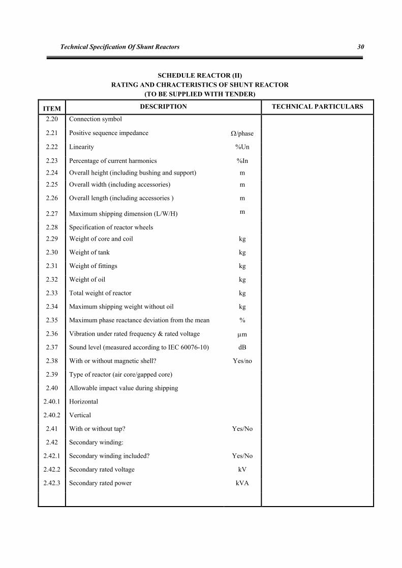
SCHEDULE REACTOR (II) RATING AND CHRACTERISTICS OF SHUNT REACTOR
(TO BE SUPPLIED WITH TENDER)
ITEM DESCRIPTION TECHNICAL PARTICULARS
2.20 Connection symbol
2.21 Positive sequence impedance Ω/phase
2.22 Linearity %Un
2.23 Percentage of current harmonics %In
2.24 Overall height (including bushing and support) m
2.25 Overall width (including accessories) m
2.26 Overall length (including accessories ) m
2.27 Maximum shipping dimension (L/W/H) m
2.28 Specification of reactor wheels
2.29 Weight of core and coil kg
2.30 Weight of tank kg
2.31 Weight of fittings kg
2.32 Weight of oil kg
2.33 Total weight of reactor kg
2.34 Maximum shipping weight without oil kg
2.35 Maximum phase reactance deviation from the mean %
2.36 Vibration under rated frequency & rated voltage µm
2.37 Sound level (measured according to IEC 60076-10) dB
2.38 With or without magnetic shell? Yes/no
2.39 Type of reactor (air core/gapped core)
2.40 Allowable impact value during shipping
2.40.1 Horizontal
2.40.2 Vertical
2.41 With or without tap? Yes/No
2.42 Secondary winding:
2.42.1 Secondary winding included? Yes/No
2.42.2 Secondary rated voltage kV
2.42.3 Secondary rated power kVA

Tables
31
SCHEDULE REACTOR (II)
RATING AND CHRACTERISTICS OF SHUNT REACTOR (TO BE SUPPLIED WITH TENDER)
ITEM DESCRIPTION TECHNICAL PARTICULARS
3 Nominal values of the terminals bushing
3.1 Rated service voltage kV
3.2 Rated current A
3.3 Insulation level at IEC condition:
3.3.1 LIWL kVpeak
3.3.2 SIWL kVpeak
3.3.3 PFWL kV
3.4 Radio influence voltage level measured at 1.1Um and 1
MHZ µvolt
3.5 Voltage which corona is not visible kV
3.6 Loss angle at nominal voltage
3.7 Total creepage distance mm
3.8 Protected creepage distance mm
3.9 Static bending failing load:
3.9.1 Vertical N
3.9.2 Horizontal N
3.10 Type of bushing
3.11 Equipped with oil level indicator? Yes/No
3.12 Dimensions:
3.12.1 Height mm
3.12.2 Diameter mm
3.13 Dynamic bending failing load N
3.14 Washable in service? Yes/No
3.15 Whether test conductor included for B.C.T? Yes/No

Technical Specification Of Shunt Reactors
32
SCHEDULE REACTOR (II)
RATING AND CHRACTERISTICS OF SHUNT REACTOR (TO BE SUPPLIED WITH TENDER)
ITEM DESCRIPTION TECHNICAL PARTICULARS
4 Nominal values of neutral terminal bushing
4.1 Rated service voltage kV
4.2 Rated current A
4.3 Insulation level at IEC condition:
4.3.1 LIWL kVpeak
4.3.2 PFWL kV
4.4 Radio influence voltage level measured at1.1 Um and 1 MHZ µvolt
4.5 Loss angle at nominal voltage
4.6 Total creepage distance mm
4.7 Protected creepage distance mm
4.8 Static bending failing load:
4.8.1 Vertical N
4.8.2 Horizontal N
4.9 Type of bushing
4.10 Equipped with oil level indictor? Yes/No
4.11 Dimensions:
4.11.1 Height mm
4.11.2 Diameter mm
4.12 Dynamic bending failing load N
5 Phase winding bushing current transformer
5.1 Ratio
5.2 Burden VA
5.3 Accuracy
5.4 No. of cores
5.5 Knee point voltage Volt
5.6 No load impedance Ω
Tables
33
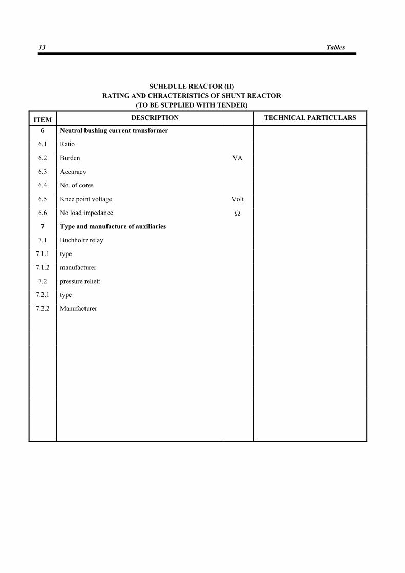
SCHEDULE REACTOR (II)
RATING AND CHRACTERISTICS OF SHUNT REACTOR (TO BE SUPPLIED WITH TENDER)
ITEM DESCRIPTION TECHNICAL PARTICULARS
6 Neutral bushing current transformer
6.1 Ratio
6.2 Burden VA
6.3 Accuracy
6.4 No. of cores
6.5 Knee point voltage Volt
6.6 No load impedance Ω
7 Type and manufacture of auxiliaries
7.1 Buchholtz relay
7.1.1 type
7.1.2 manufacturer
7.2 pressure relief:
7.2.1 type
7.2.2 Manufacturer

Technical Specification Of Shunt Reactors
34