Embed Size (px)
Citation preview
Model AV-1-300 Alarm Check Valve, 300 psi (20,7 bar) 2-1/2, 4, 6 & 8 Inch (DN65, DN100, DN150 & DN200) Vertical or Horizontal* Installation
Page 1 of 20 DECEMBER 2016 TFP910
Worldwide Contacts www.tyco-fire.com
General DescriptionThe TYCO Model AV-1-300 Alarm Check Valves are divided seat ring, rubber-faced clapper, waterflow alarm check valves that are intended for use in wet pipe (automatic sprinkler) fire protection systems. They may be installed vertically or horizontally*, and they are designed to automati-cally actuate electric and/or hydraulic alarms when there is a steady flow of water into the system that is equivalent to the discharge rate of one or more sprinklers.
A separately ordered Model RC-1 Retard Chamber (Ref. Technical Data Sheet TFP920) is required for installa-tions subject to variable pressures. It is used to help prevent false alarms asso-ciated with pressure variations in public water supplies.
The AV-1-300 Alarm Check Valve Trim includes pressure gauges to monitor system pressure conditions, a bypass check valve, a main drain valve, and an alarm test valve. The bypass check valve reduces the possibility of false alarms by permitting slow as well as small transient increases in water supply pressure to be passed through to the system without opening the waterway clapper.
NOTICEThe TYCO Model AV-1-300 Alarm Check Valves described herein must be installed and maintained in com-pliance with this document, as well as with the applicable standards of the National Fire Protection Association (NFPA), in addition to the standards of any authorities having jurisdiction. Failure to do so may impair the integ-rity of these devices.
The owner is responsible for main-taining their fire protection system and devices in proper operating con-dition. Contact the installing contrac-tor or product manufacturer with any questions.
Technical DataApprovalsUL and C-UL Listed FM Approved
Working Water Pressure Range20 to 300 psi (1,4 to 20,7 bar)
Friction LossRefer to Graph A.
End ConnectionsGroove x Groove Flange x Groove Flange x Flange Refer to Table A for size applicability
WeightsRefer to Table A.
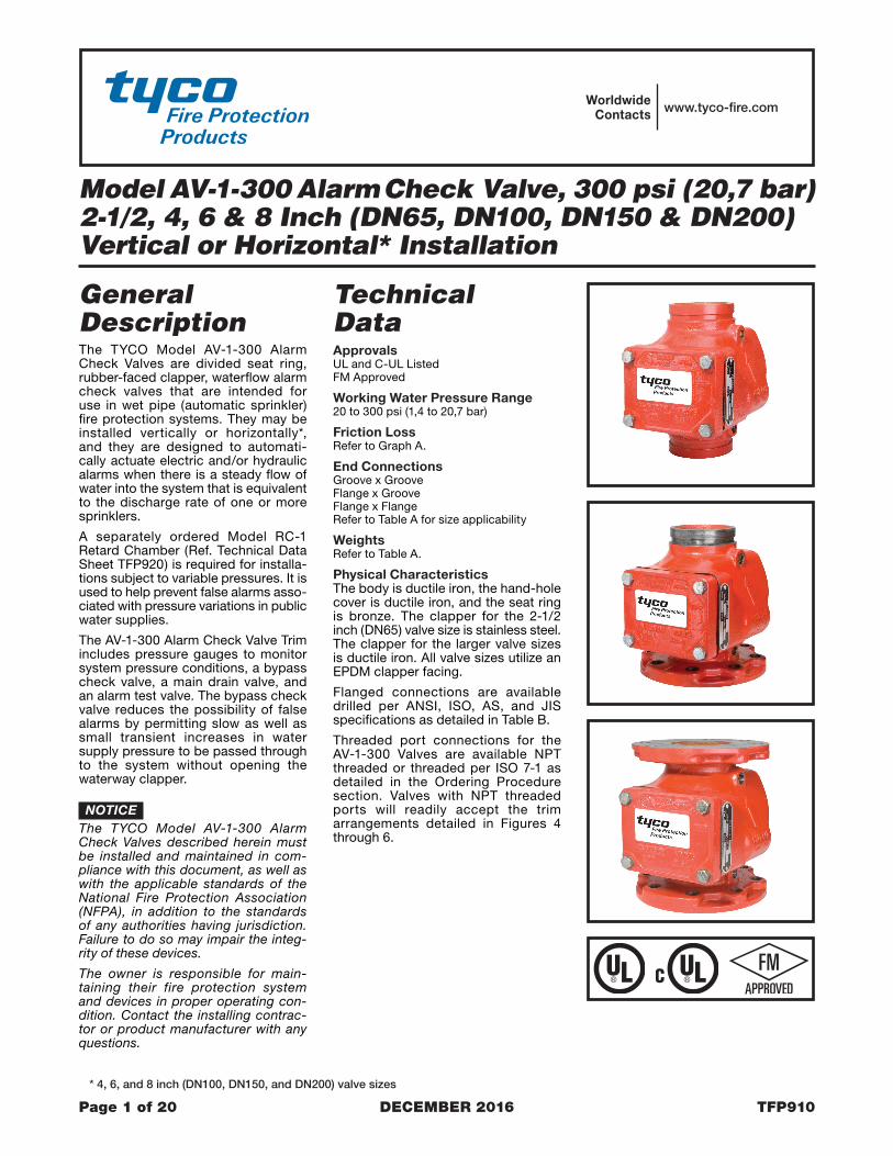
Physical CharacteristicsThe body is ductile iron, the hand-hole cover is ductile iron, and the seat ring is bronze. The clapper for the 2-1/2 inch (DN65) valve size is stainless steel. The clapper for the larger valve sizes is ductile iron. All valve sizes utilize an EPDM clapper facing.
Flanged connections are available drilled per ANSI, ISO, AS, and JIS specifications as detailed in Table B.
Threaded port connections for the AV-1-300 Valves are available NPT threaded or threaded per ISO 7-1 as detailed in the Ordering Procedure section. Valves with NPT threaded ports will readily accept the trim arrangements detailed in Figures 4 through 6.
* 4, 6, and 8 inch (DN100, DN150, and DN200) valve sizes
TFP910Page 2 of 20
Nominal Valve Size
Inches (DN)
Groove x Groove Lbs. (kg)
Flange x Groove Lbs. (kg)
Flange x Flange Lbs. (kg)
2-1/2 (65)
22 (10,0)
28 (12,7) N/A
4 (100)
38 (17,2)
47 (21,3)
57 (25,9)
6 (150)
58 (26,3)
70 (31,8)
84 (38,1)
8 (200)
102 (46,3)
120 (54,4)
149 (67,6)
1
QTY.
1
1
1
1
1
1
11
1
2
4
14
QTY.
6
6
1
4
. . . . . . .. . .
. . . . . . . . . .
. . . .
. . . . . . . .
. . .
. . .
. . . . . . .. .
. . . .
. . .
. . . . . . . . . . .
. . . . . . . . . .. . . . .
. . . . .
. . . . . . . . .
. . . . . . .
. . . . .
. . . . . . . . .
. . . . . . . . .
. . . . . . . . .
. . . . . . . . .
. . . . . . . . .
. . . . . . . . .
. . . . . .
. . . . . .
21
NO.
3
7
456
8
NO.
(a)
(b)
10
11
9
12
NO.
13
Handhole CoverValve Body NR
DESCRIPTION REF.
NR
See (a)Handhole CoverGasket
See (a) or (b)Clapper FacingClapper Washer
VALVE PARTS
Seat Ring NR
See (b)Lock Nut,2-1/2 Inch Valve See (b)Self-Locking HexCap Screw, 4, 6, & 8Inch Valves See (b)
REPLACEMENT PARTSDESCRIPTION P/N
92-200-1-41692-200-1-62092-200-1-816
92-200-1-216
92-200-1-218
See (b)Clapper Hinge PinClapper Hinge
See (b)Clapper Spring
Pin Bushing,2-1/2 Inch Valve NR
Valves4, 6, & 8 Inch
NR
Clapper See (b)
92-200-1-42392-200-1-62392-200-1-823
Hex Bolt,Handhole Cover
2-1/2 Inch Valve,
x 1-1/4" Long CH
DESCRIPTION REF.VALVE PARTS
1/2-13 UNC-2A
6 Inch Valve,
x 1-3/4" Long CH1/2-13 UNC-2A
8 Inch Valve,
x 2" Long CH3/4-10 UNC-2A
4, 6, & 8 InchPlug, 3/8" NPT,
Valves only CH
Square Head PipeClapper Hinge Pin
4 Inch Valve,
x 1-3/4" Long CH1/2-13 UNC-2A
Repair Parts Kit,Includes 3 & 6
4 Inch Valve6 Inch Valve
Clapper Assembly,Includes 5-9, 11
4 Inch Valve6 Inch Valve
8 Inch Valve
8 Inch Valve
2-1/2 Inch Valve
2-1/2 Inch ValveIncludes 5-11
F x F valve shown for reference;components for G x G and F x G
1.NOTES:
valves are shared.NR: Not ReplaceableCH: Common Hardware
2.3.
5
7
6
8
10
11
2
12
9
3
10
4
13
1
5
11
6
78
10CLAPPER
ASSEMBLY2-1/2 INCH
VALVE
CLAPPERASSEMBLY
4, 6, & 8 INCHVALVES
FIGURE 1 MODEL AV-1-300 ALARM CHECK VALVE
ASSEMBLY
TABLE A MODEL AV-1-300 ALARM CHECK VALVE
AVAILABLE VALVE END CONNECTIONS AND VALVE WEIGHTS

TFP910Page 3 of 20
6 IN
CH
(DN
150)
4 IN
CH
(DN
100)
2-1/
2 IN
CH
(DN
65)
8 IN
CH
(DN
200)
600400 1000
FLOW RATE IN LITRES PER MINUTE (LPM)(1 GPM = 3,785 LPM)
FLOW RATE IN GALLONS PER MINUTE (GPM)
0.9
300
0.8
0.7500400
NO
MIN
AL
PR
ES
SU
RE
DR
OP
IN P
OU
ND
S P
ER
SQ
UA
RE
INC
H (P
SI)
1.0
2.0
3.0
4.0
2000
NO
MIN
AL
PR
ES
SU
RE
DR
OP
IN B
AR
(1 P
SI =
0,0
6895
BA
R)
0,06
3000700 1000 2000 4000
0,05
0,08
0,07
0,090,10
0,20
1000050003000 7000 15000
200100
2 3
2
3
1
1
Same drilling as for BS 4504 Section 3.2 (PN16) and DIN 2532 (PN16).
7.50(190,5)9.50
(241,3)
0.75(19,0)0.88(22,2)
7.00(178,0)9.25
(235,0)
0.71(18,0)0.87(22,0)
6.89(175,0)
0.91(23,0)
0.75(19,0)
9.45(240,0)
11.75(298,5)
0.88(22,2)
11.50(292,0)
0.87(22,0)
11.61(295,0)
0.91(23,0)
11.42(290,0)
5.50(139,7)
0.75(19,0)
5.00(127,0)
5.51(140,0)
0.87(22,0)
0.71(18,0)
0.71(18,0)0.87(22,0)0.87(22,0)
0.71(18,0)
0.75(19,0)
4 Inch(DN100)6 Inch
(DN150)8 Inch
(DN200)
2-1/2 Inch(DN65) 4
8
8
8 8
7.09(180,0)9.45
(240,0)11.61(295,0)
5.71(145,0) 4
8
8
12
4
8
8
12
4
8
8
8
Dim.A
Dim.B
Qty. Dim.A
Dim.B
Qty. Dim.A
Dim.B
Qty. Dim.A
Dim.B
Qty. Dim.A
Dim.B
Qty.
Same drilling as for BS 4504 Section 3.2 (PN10) and DIN 2532 (PN10).Dim. A
Bolt CircleDiameter
Dim. BBolt HoleDiameter
Qty. NNumber ofBolt Holes
NominalValveSize
Same drilling as for B16.5 (Class 150) and B16.42 (Class 250).
ANSI B16.1(Class 125)
AS 2129(Table E)
ISO 2084(PN10)
JIS B 2210(10K)
Flange Drilling Speci�cationNominal Dimensions in Inches and (mm)
ISO 2084(PN16)
USEISO 2084
(PN16)
GRAPH A MODEL AV-1-300 ALARM CHECK VALVE
NOMINAL PRESSURE LOSS VERSUS FLOW
TABLE B MODEL AV-1-300 ALARM CHECK VALVE
FLANGE DRILLING SPECIFICATIONS

TFP910Page 4 of 20
OperationWhen the fire protection system is initially pressurized, water flows into the system until the water supply and system pressure become equalized, and the torsion Spring closes the Waterway Clapper in the Alarm Check Valve. Once the pressures stabilize, the Alarm Check Valve is in service and the centrally located groove in the Seat Ring is sealed. Consequently, with the Alarm Check Valve set for service, there is no flow through the alarm port to the alarm devices (i.e., water motor alarm and/or pressure alarm switch).
When there is a steady flow of water into the sprinkler system due to a sprin-kler operation, the Waterway Clapper opens as shown in Figure 2. Water is then permitted to flow into the centrally located groove in the Seat Ring and out through the alarm port towards the Restriction Assembly (Figure 3). When the flow through the Inlet Restriction of the Restriction Assembly exceeds the flow through the Outlet Restriction, the Retard Chamber (where provided for systems with variable pressure), begins to fill.
Subsequently, the Water Motor Alarm and/or the pressure alarm switch will be actuated. The alarms will continue to be actuated as long as the Water-way Clapper remains open. Water in the alarm lines will automatically drain out through the 1/8 inch (3,2 mm) Drain Orifice in the Restriction Assembly (Figure 3) when the Waterway Clapper closes (due to a stop in the flow of water into the sprinkler system).
For variable pressure systems, slow as well as small transient increases in water supply pressure may continue to build up in the system (via the Bypass Check Valve) without opening the Waterway Clapper.
A transient surge in supply pres-sure that is sufficient only to open the Waterway Clapper momentarily will not cause a false alarm, and a portion of the increase in pressure will be trapped within the system, thus reducing the possibility of another opening. Any water in the alarm line is automatically drained, further reducing the possibil-ity of a false alarm due to a successive transient surge in supply pressure.
Design CriteriaIn planning installation of the TYCO Model AV-1-300 Alarm Check Valves, consideration must be given to the dis-posal of the large quantities of water that may be associated with draining the system or performing a flow test.
Valves installed in the vertical position must have the flow going up. Valves installed in the horizontal position must be positioned so that the drain connec-tion points down.
The sprinkler system designer must be aware that the configuration of the piping network and its tendency to trap pockets of air (such as in the case of a peaked-roof gridded system) can affect the performance of the alarm system. Although a slight amount of trapped air is desirable to prevent significant pressure increases due to thermally induced expansion of the water, a large quantity of trapped air in a system may result in the possibility of an intermit-tent alarm.
The possibility of an intermittent alarm condition is a consequence of the fact
PRESSUREWATERFLOW
ALARM SWITCH
MOTOR ALARM
VALVE
RESTRICTION
(3,2 mm)
OUTLETORIFICE
RETARD CHAMBERBEGINS TO FILL
INLET EXCEEDS OUTLET,RESTRICTION ASSEMBLYWHEN FLOW THROUGH
ASSEMBLY
1/8"
CHAMBERRETARD
INLET
ALARM PORTRING GROOVE AND
THROUGH SEATWATERFLOW
MAINDRAIN
ALARM ACTUATE
WATERFLOW PRESSURECHAMBER OVERFLOWS,
ONCE RETARD
WATER MOTORALARM SWITCH AND
WATERFLOWTO SYSTEM
WATERFLOWTO WATER
7/32"
ORIFICE(5,6 mm)
UPON SPRINKLERFLOW, WATERWAYCLAPPER OPENS
GAUGE
GAUGE
SUPPLYPRESSURE
PRESSURESYSTEM
CHECKVALVE
ALARM
SCREEN
DRAIN RESTRICTIONWITH 0.125" (3,2 mm)ORIFICE
INLET RESTRICTIONWITH 0.219" (5,6 mm)ORIFICE
FIGURE 2 MODEL AV-1-300 ALARM CHECK VALVE
OPERATION
FIGURE 3 RESTRICTION ASSEMBLY
(Provided with Alarm Check Valve Trim)

TFP910Page 5 of 20
that the flow out of the system through the test valve or a single sprinkler is very small relative to the flow that can be passed through the valve. This dif-ference increases with valve size. If the system were free of trapped air, flow in would equal flow out and the Waterway Clapper would always stabilize at some open position (as needed to accommo-date the required flow). With trapped air in the system, however, the Water-way Clapper first opens wider since the system initially demands greater flow until the air pockets are compressed (back to nearly the supply pressure), and then it will tend to return closer to the Seat Ring. If the volume of the air pockets is excessive, flow into the system can be momentarily reduced to nearly zero (once the air pockets are compressed) and the Waterway Clapper may close, causing flow to the alarms to be shutoff.
After the Waterway Clapper has closed, sufficient water must flow out of the system before the Waterway Clapper will again open. A repetition of the above described condition is termed an intermittent alarm.
Using a vent (which can also serve as an end-of-line Inspector’s Test Con-nection) piped from the top of a cross main or end of a branch line at the point most remote from the alarm valve, and filling the system slowly in accordance with the steps described in the Setting Procedure section, can prevent an excessive amount of air from being trapped.
InstallationNOTICE
Proper operation of the TYCO Model AV-1-300 Alarm Check Valves depends upon the trim described in this data sheet installed in accordance with the following instructions. Failure to follow the appropriate trim installation instruc-tions may prevent the device from func-tioning properly as well as void listings/approvals and the manufacturer’s warranties.
The Alarm Check Valves must be installed in readily visible and acces-sible locations.
It is recommended that provision be made for viewing the alarm line drain water by locating the main drain outlet in a readily visible area.
Wet pipe fire protection systems must be maintained at a minimum tempera-ture of 40°F (4°C).
Step 1. Trim the Alarm Check Valve in accordance with Figure 4, 5, or 6, as applicable. Apply pipe-thread sealant sparingly to male threads only.
Step 2. The Alarm Vent Trim illustrated in Figure 8 must be installed if a water motor alarm is not to be used.
Step 3. Plug unused alarm connections.
Step 4. Suitable provision must be made for disposal of alarm line and system drainage water. Drainage water must be directed so that it will not cause damage or result in danger-ous conditions.
Step 5. The alarm line drain must be arranged so that there will be no danger of freezing.
Step 6. The check valve in the exter-nally mounted bypass around the Waterway Clapper must be installed with its arrow pointed up, and the drain check valve must be installed with its arrow pointing towards the drain.
Step 7. It is recommended that a vent connection (which may also be used as an end-of-line Inspector’s Test Con-nection), be piped from a cross main or branch line at the point most remote from the alarm valve. The vent line should be connected to the top of a cross main or to the end of a branch line and be located at the highest level of a multi-level installation.
The vent connection can be used to bleed-off excessive air from the system, and therefore, minimize the possibility of a false alarm due to a transient surge in supply pressure. The contraction/expansion associated with an exces-sive amount of trapped air could also cause the Waterway Clapper to cycle open and shut during an inspector’s test or during a discharge by a single sprinkler.
Setting ProcedureSteps 1 through 11 are to be performed when initially setting the Model AV-1-300 Alarm Check Valve or after system operation due to a fire.
NOTICEFilling the system with water will result in operation of the associated alarms. Consequently, notification must first be given to the owner and fire department, central station, or other signal station to which the alarms are connected.
Notify the proper authorities and all personnel who may be affected that an alarm test is to be performed.
After placing a fire protection system in service, notify the proper authorities
and advise those responsible for moni-toring proprietary and/or central station alarms.
Step 1. Open the 1/4 inch Gauge Test Valves for the Supply and System Pres-sure Gauges.
Step 2. Check to see that the Hand-hole Cover bolts are tight. If not, cross-tighten them.
Step 3. Close the Alarm Test Valve.
Step 4. Open the remote cross main or branch line vent connection. (Refer to Step 7 in the Installation section.)
Step 5. Slowly open the main control valve until the sound of flowing water just begins and then open the valve one more turn.
Step 6. Close the remote branchline vent connection after the discharge of aerated water ceases, and the outlet has flowed full for at least 15 seconds.
Step 7. Fully open the main control valve.
Step 8. Open the end-of-line Inspec-tor’s Test Connection (or Alarm Test Valve, if acceptable to the authority having jurisdiction) and verify that the system alarms operate.
Step 9. Close the end-of-line Inspec-tor’s Test Connection (or Alarm Test Valve).
Step 10. Verify that water ceases to flow from the alarm line drain. If water continues to flow, follow the corrective procedure described in the Care and Maintenance section.
The Restriction Assembly has a 1/8 inch (3,2 mm) diameter drain orifice. Sufficient time must be allowed for drainage of the Retard Chamber and the piping to the water motor alarm.
Step 11. After verification that the flow of water out of the alarm line drain has stopped, the alarm valve is set and is ready for service.
TFP910Page 6 of 20
11
22
2
QTY.
2
11
1
1
1
2
2
11
1
21
2
7
1
11
1
11
2
21
QTY.
. . . . . . .. . . . . . . . .
. ..
. .
. . . . . . . . . . . . .
. . . . . . . . .. . . . . . . . . . . .
. . . . . . . . .
. . . .
. . . . . . . . . . . .
. . . . . . . . . . . .
. .. . . . . . .
. . . . . .
. . . .
. . . .
. . . . . . . . . . . . . .
. . . . .
. . . . . . . .
. . . .
. . . .
. . . . .
. . . . . . . .
. . . . . . . .
. . . . . . . .
. . . . . . . .. . . . .
12
1413
6
1
4
10
5
11
23
89
7
NO.
15
19
1718
16
22
27
2928
24
2625
23
2021
NO.
1-1/4" Angle Valve
Alarm Test Tube
Connector
Connector
1/2" Union1/4" 90° Elbow
1/4" Plug
1/2" NPT x 5/8" Tube
External By-Pass Tube
Restriction Assembly
1/2" NPT x 1/2" Tube
300 psi/ 2000 kPa
1/2" Globe Valve 46-047-1-0041/2" Y-Strainer 52-353-1-005
Water Pressure Gauge1/4" Gauge Test Valve1/2" Swing Check Valve
46-005-1-00246-049-1-004
92-343-1-005
DESCRIPTION P/N
CH
CHCH
CH
92-210-2-005
1/2" 90° Elbow
CH1-1/4" x 1-1/4" x 1/2" Tee
CH
CH
92-304-1-01792-304-1-047
46-048-1-007
CH1/2" x 1/4" x 1/2" Tee1/2" x 1/2" x 3/4" Tee CH
1/2" Tee CH
P/N
CH1/2" x 1-1/2" Nipple
CH1/2" x 6" Nipple
1-1/4" x 3-1/2" Nipple CH1-1/4" x 2-1/2" Nipple CH
CH1/2" x 2-1/2" Nipple
1/2" x 4" Nipple1/2" x 3" Nipple
CHCH
1/2" x 2" Nipple CH
CH1/4" x 1" Nipple1/4" x 2-1/2" Nipple CH
DESCRIPTION
1-1/4 INCH NPTCONNECTION
TO DRAIN
1/2 INCH NPTCONNECTION
FOR WATERFLOWPRESSURE ALARM
SWITCH
RESTRICTIONASSEMBLY,
SEE FIGURE 3
3/4 INCH NPTCONNECTION FOR
WATER MOTORALARM
3/4 INCH NPTCONNECTION FOR
WATER MOTORALARM
1/2 INCH NPTCONNECTION
FOR WATERFLOWPRESSURE ALARM
SWITCH
MAINDRAIN VALVE(NORMALLY
CLOSED)
ALARMTEST VALVE(NORMALLY
CLOSED)
MODEL RC-1RETARD
CHAMBER
ORDEREDSEPARATELY
(FOR VARIABLEPRESSURESYSTEMS)
SYSTEMPRESSURE
GAUGE
MODEL AV-1ALARM VALVE,
2-1/2 INCH (DN65)GROOVE x GROOVE
SHOWN
SUPPLYPRESSURE
GAUGE
EXTERNALBY-PASS
TUBE ALARMTEST TUBE
LOCATIONFOR OPTIONALELECTRICALLYSUPERVISEDN.O. ALARMCONTROL
VALVE
LOCATIONFOR OPTIONALELECTRICALLYSUPERVISEDN.O. ALARMCONTROL
VALVE
All Fittings and Nipples are galvanized(Standard Order).CH: Common Hardware.
NOTES:1.
2.
15 1322 22
22
6
2222
5
18
4
21
223
19
29
7
28
242716
23
26
2017
14
2
12
2
3
1610
11
811
23
22
25
1720
109
1
121
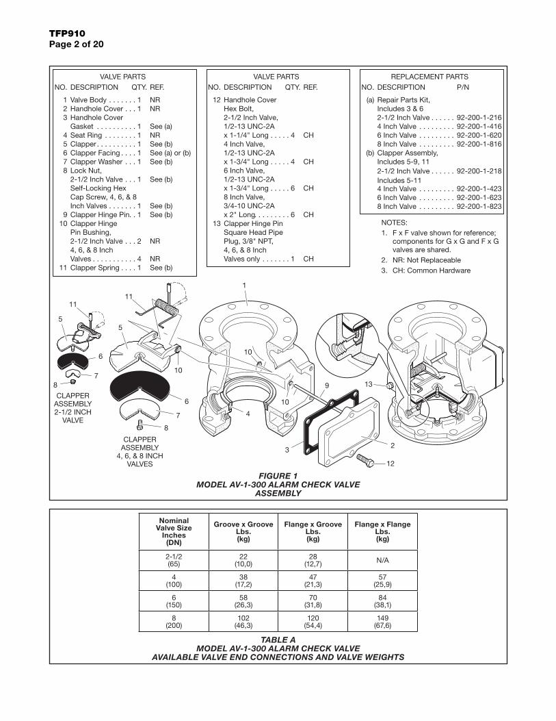
FIGURE 4 (1 OF 3) VERTICAL CLOSED DRAIN TRIM — STANDARD ORDER
FOR 2-1/2 INCH (DN65) MODEL AV-1-300 ALARM CHECK VALVES (P/N 52-204-4-950)

TFP910Page 7 of 20
2
1
1
13
21
2
2
45
1
2
11
22
QTY. QTY.
1
11
11
4
1
22
11
1
. . . . . . . . . .
. . . . .
. . . .
. . . . . . . .
. . . . . . . .
. . . . . . . .
. . . . . . . . . . . . . .. . . . . . . . . . . .
. . . . . . . . .. . . . . . . . . . . . .
. . . . .
. . . . .
. . . . . . . . .
. . . . . . . . .
. . . . . . . . . . . . . .
. . . . . . .. . . . . . . . .
.
. .
. .
. . . .
. . . . . . .
. . . .
. . . . .
. .
. .
. . . . . . . .. . . . .
. . . . .
29
17
6
10
89
7
21
22
1920
18
3
54
2
1
NO.
14
1615
1213
11
26
2827
2425
23
NO.
CH2" x 3" Nipple
CH1/4" x Close Nipple
Restriction Assembly 92-210-2-005
1/2" x 1-1/2" Nipple1/2" x Close Nipple
Bushing1/2" Union
2" Angle Valve
1/2" x 1/4" Reducing1/4" Plug
46-048-1-009
CHCH
CH
1/2" x 2" Nipple
1/2" x 3" Nipple
1/4" x 4" Nipple
CH
CH
CH
CHCH
1/2" x 1/4" x 1/2" Tee1/2" x 1/2" x 3/4" Tee
2" x 2" x 1/2" Tee
1/2" Globe Valve1/2" Swing Check Valve
Water Pressure Gauge300 psi/ 2000 kPa
DESCRIPTION
1/2" Y-Strainer
1/4" Gauge Test Valve
46-047-1-00446-049-1-004
92-343-1-005
52-353-1-005
46-005-1-002
P/N
1/2" 90° Elbow1/2" 45° Elbow
1/2" Tee
CHCH
CHCH
CH
CH
1/2" x 6-1/2" Nipple
1/2" x 5" Nipple1/2" x 3-1/2" Nipple
Select Nipple per TableSelect Nipple per Table
1/2" x 5-1/2" Nipple
DESCRIPTION
CH
CHCH
CHCH
CH
P/N
Select Appropriate Nipple Sizesper AV-1 Alarm Check Valve Size
4 Inch (DN100)1/2" x 1-1/2"1/2" x 3-1/2"
2728
NippleNumber
6 Inch (DN150)1/2" x 2-1/2"1/2" x 4-1/2"
All Fittings and Nipples are galvanized(Standard Order).
Install subassemblies in alphabetical order.NOTES:
3.
1.2.
CH: Common Hardware.
2 INCH NPTCONNECTION
TO DRAIN
1/2 INCH NPTCONNECTION
FOR WATERFLOWPRESSURE ALARM
SWITCH
1/2 INCH NPTCONNECTION
FOR WATERFLOWPRESSURE ALARM
SWITCH
RESTRICTIONASSEMBLY,
SEE FIGURE 3
3/4 INCH NPTCONNECTION FOR
WATER MOTORALARM
3/4 INCH NPTCONNECTION FOR
WATER MOTORALARM
MAINDRAIN VALVE(NORMALLY
CLOSED)
ALARMTEST VALVE(NORMALLY
CLOSED)
MODEL RC-1RETARD
CHAMBER
ORDEREDSEPARATELY
(FOR VARIABLEPRESSURESYSTEMS)
SYSTEMPRESSURE
GAUGE
MODEL AV-1ALARM VALVE,6 INCH (DN150)
FLANGE xFLANGESHOWN
SUPPLYPRESSURE
GAUGE
1/2" x 1-1/2"(4 INCH VALVE)
or1/2" x 2-1/2"
(6 INCH VALVE)
1/2" x 3-1/2"(4 INCH VALVE)
or1/2" x 4-1/2"
(6 INCH VALVE)
LOCATIONFOR OPTIONALELECTRICALLYSUPERVISEDN.O. ALARMCONTROL
VALVE
LOCATIONFOR OPTIONALELECTRICALLYSUPERVISEDN.O. ALARMCONTROL
VALVE
K
H
MN
C
A
L B
D
E
I
G
JF
111919 203
6
19
10
7
2022
21
12 20
11
19
1426
5
15
20
11
16
29
29
1024
3 20
1317
4
10
25
27 23
28
2111
22
2 8
181
29
8
1
FIGURE 4 (2 OF 3) VERTICAL CLOSED DRAIN TRIM — STANDARD ORDER — SEMI-PREASSEMBLED
FOR 4 & 6 INCH (DN100 & DN150) MODEL AV-1-300 ALARM CHECK VALVES (P/N 52-204-4-951)

TFP910Page 8 of 20
1
1
1
2
12
1
1
33
2
1
11
1
1
11
22
QTY. QTY.
1
12
21
1
1
12
22
1
1
. . . . . . . . .
. . . . . . .
. . . . .. . . .
. . . . . . . . . . . .
. . . . . . . . .. . . . . . . . . . . . .
. . . . . . .. . . . . . . . . .
. . . . . . . .. . . . .
. . . . . . . .
. . . . .
. . . . .
. . . . .
. . . . . . . . .
. . . . . . . . .. . . . . . . . . . . . . .
. . . . . . . . . . . .
. . . . . . .
.
.
. .
. .. . . . . . . .
. . . . .
. . . . .
. . . . .
. . . . .
. . . . .
. . . .
. . . .
. . . .
17
6 28
10
89
7
21
1920
18
32
3031
29
3
54
2
1
NO.
14
1615
1213
11
25
2726
2324
NO.
33
22
2" x 2" x 1/2" Tee
1/2" Y-Strainer 52-353-1-005
CH
3/4" x 2-1/2" Nipple CH
1/4" x 1-1/2" Nipple
1/2" x 1-1/2" Nipple1/2" x Close Nipple
Restriction Assembly
1/2" Union
2" Angle Valve1/4" Plug
92-210-2-00546-048-1-009
CHCH
1/2" x 2" Nipple
CH
CH
CHCH
2" x 3-1/2" Nipple2" x 3" Nipple
3/4" x 3" Nipple3/4" x 4-1/2" Nipple
CHCH
CHCH
3/4" x 1/4" x 3/4" Tee3/4" x 3/4" x 1/2" Tee
1/2" Globe Valve
1/2" Swing Check Valve
Water Pressure Gauge300 psi/ 2000 kPa
DESCRIPTION
1/4" Gauge Test Valve
3/4" Swing Check Valve46-047-1-004
46-049-1-004
92-343-1-00546-005-1-002
46-049-1-005
P/N
1/2" Tee
1/2" 90° Elbow1/2" 45° Elbow
3/4" Union
CHCH
CHCH
CH
CH
1/2" x 3" Nipple1/2" x 3-1/2" Nipple
3/4" x 1-1/2" Nipple
1/2" x 6-1/2" Nipple1/2" x 4-1/2" Nipple
3/4" x Close Nipple
DESCRIPTION
CH
CHCH
CHCH
CH
P/N
CH1/2" x 1/2" x 3/4" Tee
All Fittings and Nipples are galvanized(Standard Order).
Install subassemblies in alphabetical order.NOTES:
3.
1.2.
CH: Common Hardware.
2 INCH NPTCONNECTION
TO DRAIN
1/2 INCH NPTCONNECTION
FOR WATERFLOWPRESSURE ALARM
SWITCH
1/2 INCH NPTCONNECTION
FOR WATERFLOWPRESSURE ALARM
SWITCH
RESTRICTIONASSEMBLY,
SEE FIGURE 3
3/4 INCH NPTCONNECTION FOR
WATER MOTORALARM
3/4 INCH NPTCONNECTION FOR
WATER MOTORALARM
MAINDRAIN VALVE(NORMALLY
CLOSED)
ALARMTEST VALVE(NORMALLY
CLOSED)
MODEL RC-1RETARD
CHAMBER
ORDEREDSEPARATELY
(FOR VARIABLEPRESSURESYSTEMS)
SYSTEMPRESSURE
GAUGE
SUPPLYPRESSURE
GAUGE
MODEL AV-1ALARM VALVE,8 INCH (DN200)
FLANGE x GROOVESHOWN
LOCATIONFOR OPTIONALELECTRICALLYSUPERVISEDN.O. ALARMCONTROL
VALVE
LOCATIONFOR OPTIONALELECTRICALLYSUPERVISEDN.O. ALARMCONTROL
VALVE
32012
20 21
7
10
218
2123
13
620
1526
14
19
18
33
32
2817
16
2
9
9
2
2425
1025
524
1222
27
30
29
11
4
31
27
1619
1
1
FIGURE 4 (3 OF 3) VERTICAL CLOSED DRAIN TRIM — STANDARD ORDER — SEMI-PREASSEMBLED FOR 8 INCH (DN200) MODEL AV-1-300 ALARM CHECK VALVES (P/N 52-204-4-952)
TFP910Page 9 of 20
2
1
2
1
11
1
11
2
11
1
2
1
1
12
11
2
32
1
12
2
QTY.
2
QTY.
11
1
2
. . . . . . . . . . . . . .
. . . . . . .
. .
. . . . . . . . .. . . .
. . . . . . ..
. . . . . . . .. . . . . . . . . . .
. . . . . . . . . . . .
. . . . . . . . . . .. . . . . . . . . . . . . .
. . . . . . . . . . .
. . . . . . . . . . . .
. . . .
. . . .
. . . . .
. . . . .
. . . . .. . . . . . . .
. . . . . . . .
. . . . . . . .
. . . . . . . .
. . . . . . . .
. . . .
. . . .
. .
. . . . . .. .
. . . . . . . . .
. . . . . . . . . . . . .
19
9
22122
20
26
2930
2827
252423
3231
6
45
3
1516
1314
12
11
10
18
17
NO.
1
NO.
87
1/2" Tee CH46-005-1-002
Alarm Test Tube
1/4" Gauge Test Valve
92-304-1-047
Restriction Assembly
1/2" Swing Check Valve1/2" Globe Valve1/2" Y-Strainer 52-353-1-005
46-047-1-00446-049-1-004
92-210-2-005
1/2" NPT x 1/2" Tube
1/2" NPT x 5/8" Tube
Support BracketDrip Funnel
Connector
Support Bar
PVC NippleJam Nut
Connector
92-343-1-00692-343-1-007
CH
92-304-1-014
92-640-1-00992-640-1-037
CH
1/2" x 2-1/2" Nipple1/2" x 3" Nipple1/2" x 4" Nipple1/2" x 5" Nipple1-1/4" x 2-1/2" Nipple1-1/4" x 8-1/2" Nipple
1-1/4" x 1-1/4" x 1/2" Tee1/4" x 1" Nipple
1/2" x 2" Nipple1/2" x 1-1/2" Nipple1/4" x 2-1/2" Nipple
1/2" x 1/2" x 3/4" Tee1/2" x 1/4" x 1/2" Tee
CH
CHCHCH
CHCH
CH
CHCH
CH
CHCHCH
300 psi/ 2000 kPaWater Pressure Gauge
DESCRIPTION
92-343-1-005
P/N
External By-Pass Tube1-1/4" Angle Valve
DESCRIPTION
46-048-1-00792-304-1-017
P/N
1/4" 90° Elbow
1/4" Plug CH
CH
All Fittings and Nipples are galvanized(Standard Order).CH: Common Hardware.
NOTES:1.
2.
SUPPORTBRACKET
SUPPORTBAR
EXTERNALBY-PASS
TUBE ALARMTEST TUBE1/2 INCH NPT
CONNECTIONFOR WATERFLOWPRESSURE ALARM
SWITCH
1/2 INCH NPTCONNECTION
FOR WATERFLOWPRESSURE ALARM
SWITCH
RESTRICTIONASSEMBLY,
SEE FIGURE 3
3/4 INCH NPTCONNECTION FOR
WATER MOTORALARM
3/4 INCH NPTCONNECTION FOR
WATER MOTORALARM
MAINDRAIN VALVE(NORMALLY
CLOSED)
ALARMTEST VALVE(NORMALLY
CLOSED)
MODEL RC-1RETARD
CHAMBER
ORDEREDSEPARATELY
(FOR VARIABLEPRESSURESYSTEMS)
SYSTEMPRESSURE
GAUGE
SUPPLYPRESSURE
GAUGE
DRIPFUNNEL
MODEL AV-1ALARM VALVE,
2-1/2 INCH (DN65)GROOVE x GROOVE
SHOWN
1-1/4 INCH NPTCONNECTION
TO DRAIN
1-1/4 INCH NPTCONNECTION
TO DRAIN
LOCATIONFOR OPTIONALELECTRICALLYSUPERVISEDN.O. ALARMCONTROL
VALVE
LOCATIONFOR OPTIONALELECTRICALLYSUPERVISEDN.O. ALARMCONTROL
VALVE
1925
32
22
31 12
16
25
6
14 15
13
30
22
317
275
21
264
10 2519
11
8
10326
11
242
2029
23
23
28
20
18
2
17
9
1
17
1
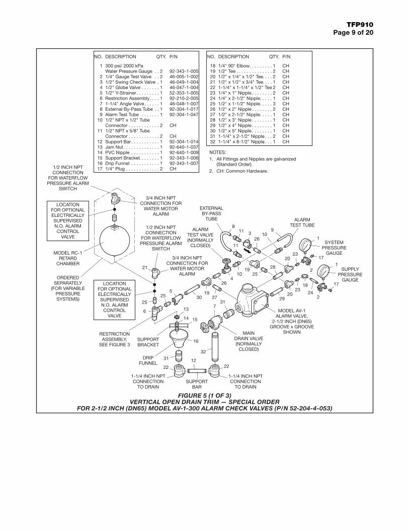
FIGURE 5 (1 OF 3) VERTICAL OPEN DRAIN TRIM — SPECIAL ORDER
FOR 2-1/2 INCH (DN65) MODEL AV-1-300 ALARM CHECK VALVES (P/N 52-204-4-053)
TFP910Page 10 of 20
21
1
12
11
1
3
4
11
2
12
1
11
22
QTY.
3
11
12
1
11
11
2
QTY.
. .. . . .
. . . .
. . . . . . . . . . . . .
. . . . . . . . .
. . . . . . . . . . .
. .. . . .
. . . . . . . . . . . . . .
. . . . .
. . . . .
. . . . . . . .. . . . .
. . . . . . . . . .. .
. . . . . . .. . . . . . . . .
.
. .
. .
. . . . . . . . . . . . . .. . . . . . . . . . . .
. . . . . . . . .
. . . . . . . . .. . . .
. . . . .
. . . . .. . . . . . . .
. . . . . . . .
. . . . . . . .
. . . . .
296
17
1011
7
98
22
18
2019
21
3130
345
1
2
NO.
13
12
1516
14
26
2827
2425
23
NO.
CHSelect Nipple per Table92-210-2-005Restriction Assembly
1/2" x 1/2" x 3/4" Tee CH
46-048-1-009
92-211-1-00392-211-1-005
92-343-1-0071/4" Plug
2" Angle Valve
Drip Funnel BracketDrip Funnel
Drip Funnel Connector
CH
1/2" x 1-1/2" Nipple
1/4" x 4" Nipple1/2" x Close Nipple
1/4" x Close Nipple1/2" Tee
CH
CH
CHCH
CH
Select Nipple per Table2" x 3" Nipple CH
CH
92-343-1-00546-005-1-002
52-353-1-00546-047-1-00446-049-1-004
DESCRIPTION
1/2" Swing Check Valve
1/2" Y-Strainer1/2" Globe Valve
Water Pressure Gauge1/4" Gauge Test Valve
300 psi/ 2000 kPa
P/N
1/2" x 1/4" Reducing
1/2" x 1/4" x 1/2" Tee
1/2" 90° Elbow1/2" 45° Elbow
Bushing1/2" Union
CH
CHCH
CHCH
1/2" x 6-1/2" Nipple
1/2" x 3-1/2" Nipple1/2" x 5" Nipple
1/2" x 2" Nipple1/2" x 3" Nipple
1/2" x 5-1/2" Nipple
DESCRIPTION
CH
CHCH
CHCH
CH
P/N
All Fittings and Nipples are galvanized(Standard Order).
Install subassemblies in alphabetical order.NOTES:
3.
1.2.
CH: Common Hardware.
Select Appropriate Nipple Sizesper AV-1 Alarm Check Valve Size
4 Inch (DN100)29 1/2" x 1-1/2"30 1/2" x 3-1/2"
NippleNumber
1/2" x 2-1/2"1/2" x 4-1/2"
6 Inch (DN150)
2 INCH NPTCONNECTION
TO DRAIN
1/2 INCH NPTCONNECTION
FOR WATERFLOWPRESSURE ALARM
SWITCH
1/2 INCH NPTCONNECTION
FOR WATERFLOWPRESSURE ALARM
SWITCH
RESTRICTIONASSEMBLY,
SEE FIGURE 3
3/4 INCH NPTCONNECTION FOR
WATER MOTORALARM
3/4 INCH NPTCONNECTION FOR
WATER MOTORALARM
MAINDRAIN VALVE(NORMALLY
CLOSED)
ALARMTEST VALVE(NORMALLY
CLOSED)
MODEL RC-1RETARD
CHAMBER
ORDEREDSEPARATELY
(FOR VARIABLEPRESSURESYSTEMS)
SYSTEMPRESSURE
GAUGE
MODEL AV-1ALARM VALVE,6 INCH (DN150)
FLANGE xFLANGESHOWN
SUPPLYPRESSURE
GAUGE
DRIPFUNNEL
1-1/4 INCH NPTCONNECTION
TO DRAIN
1/2" x 1-1/2"(4 INCH VALVE)
or1/2" x 2-1/2"
(6 INCH VALVE)
1/2" x 3-1/2"(4 INCH VALVE)
or1/2" x 4-1/2"
(6 INCH VALVE)
LOCATIONFOR OPTIONALELECTRICALLYSUPERVISEDN.O. ALARMCONTROL
VALVE
LOCATIONFOR OPTIONALELECTRICALLYSUPERVISEDN.O. ALARMCONTROL
VALVE
H
B
K
C
A
G
I J
D
F E
30
22
22
23
8
9
10
18
6
2221
21
15
147 31
1326
14
3 22
181728
521
27
29 2513
1423
1619
11
11
4
24
2
120
122
1
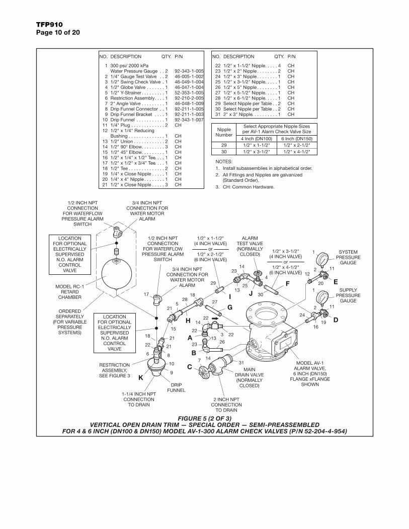
FIGURE 5 (2 OF 3) VERTICAL OPEN DRAIN TRIM — SPECIAL ORDER — SEMI-PREASSEMBLED
FOR 4 & 6 INCH (DN100 & DN150) MODEL AV-1-300 ALARM CHECK VALVES (P/N 52-204-4-954)

TFP910Page 11 of 20
2
1
1
1
11
1
32
1
1
11
1
1
11
22
QTY.
1
21
11
2
2
21
21
QTY.
1
1
. . . .
. . . . .
. . . .
. . . . . . . . . . .. . . .
. . . . . . . . .. .
. . . . .
. . . . .
. . . .
. . . . . . . .. . . . .
. . . . .. . . . . . . . . .
. . . . . . . . .. . . . . . .
.
. .
. .
. . . . . . . . . . . .. . . . . . . . . . . . .
. . . . . . . . . . . . . .
. . . . . . . . . . . .. . . . . . . . .. . . . . . . . .
. . . . .
. . . . .
. . . . .
. . . . .
. . . . . . . .
. . . .
. . . . .
28
17
6
10
89
7
21
19
20
18
32
3031
29
3
54
2
1
NO.
14
1615
1213
11
25
2726
2324
NO.
22
CH
3/4" x 1-1/2" Nipple CH
92-210-2-005Restriction Assembly
3/4" x 1/4" x 3/4" Tee
92-211-1-00592-211-1-00392-343-1-007
46-048-1-009Drip Funnel Connector
Drip FunnelDrip Funnel Bracket
2" Angle Valve
1/4" x 1-1/2" Nipple1/2" x Close Nipple
3/4" x 3/4" x 1/2" Tee
CHCH
CH
2" x 3" Nipple3/4" x 4-1/2" Nipple3/4" x 3" Nipple3/4" x 2-1/2" Nipple
CH
CHCH
CH
92-343-1-005
46-049-1-00546-005-1-002
52-353-1-00546-047-1-004
DESCRIPTION
Water Pressure Gauge300 psi/ 2000 kPa
3/4" Swing Check Valve1/4" Gauge Test Valve
1/2" Y-Strainer1/2" Globe Valve
P/N
1/2" 90° Elbow1/2" 45° Elbow1/2" Tee
3/4" Union1/2" Union1/4" Plug
CH
CHCH
CHCH
CH
1/2" x 6-1/2" Nipple3/4" x Close Nipple
1/2" x 3-1/2" Nipple1/2" x 4-1/2" Nipple
1/2" x 2" Nipple
DESCRIPTION
CHCHCH
CHCH
P/N
CH1/2" x 1/2" x 3/4" Tee
1/2" x 1-1/2" Nipple CH
All Fittings and Nipples are galvanized(Standard Order).
Install subassemblies in alphabetical order.NOTES:
3.
1.2.
CH: Common Hardware.
DRIPFUNNEL 2 INCH NPT
CONNECTIONTO DRAIN1-1/4 INCH NPT
CONNECTIONTO DRAIN
1/2 INCH NPTCONNECTION
FOR WATERFLOWPRESSURE ALARM
SWITCH
1/2 INCH NPTCONNECTION
FOR WATERFLOWPRESSURE ALARM
SWITCH
RESTRICTIONASSEMBLY,
SEE FIGURE 3
3/4 INCH NPTCONNECTION FOR
WATER MOTORALARM
3/4 INCH NPTCONNECTION FOR
WATER MOTORALARM
MAINDRAIN VALVE(NORMALLY
CLOSED)
ALARMTEST VALVE(NORMALLY
CLOSED)
MODEL RC-1RETARD
CHAMBER
ORDEREDSEPARATELY
(FOR VARIABLEPRESSURESYSTEMS)
SYSTEMPRESSURE
GAUGE
SUPPLYPRESSURE
GAUGE
MODEL AV-1ALARM VALVE,8 INCH (DN200)
FLANGE x GROOVESHOWN
LOCATIONFOR OPTIONALELECTRICALLYSUPERVISEDN.O. ALARMCONTROL
VALVE
LOCATIONFOR OPTIONALELECTRICALLYSUPERVISEDN.O. ALARMCONTROL
VALVE G
E
H
A
F
D
C
B
8
9
107
15
2116
6
22 21
32
21
1726
5
16 2425
12 424
25
1423
20
2819
18
27
29
30
13
3
31
27
1820
1
11
2
1
2
11
FIGURE 5 (3 OF 3) VERTICAL OPEN DRAIN TRIM — SPECIAL ORDER — SEMI-PREASSEMBLED
FOR 8 INCH (DN200) MODEL AV-1-300 ALARM CHECK VALVES (P/N 52-204-4-955)

TFP910Page 12 of 20
3
12
1
1
1
81
11
1
235
11
QTY.
2
21
2
22
1
22
1
QTY.
. . . . . . . .
. . . . . . . .. . . . .
. . . . . . . . .
. . . . . . .
. . . . . . . .
. . . . . . . . . . . . .. . . . . . . . .
. . . . . . . . . . . . . .
. . . . . . . . .. . . . . . . . . . . .
. . . .
. . . . .
. . . . .
. . . .
. . . .
. . . . . . .
. .
.. .
. .. . . . . . .
. . . . . . . .
. .
. .
. . . . .
1920
5
12
1617
131415
18
1011
89
76
NO.
34
2
1
2526
21
2324
22
NO.
92-210-2-005
CH
46-047-1-009CH
CHCH
46-005-1-002
52-353-1-005
92-343-1-005
46-049-1-00446-047-1-004
P/N
CH
CHCH
CHCH
CH
CHCH
CH1/2" x 2" Nipple
1/2" x 3-1/2" Nipple1/2" x 3" Nipple
Restriction Assembly
2" x 2" x 1/2" Tee
1/4" Plug2" Globe Valve
1/4" x Close Nipple1/4" x 4" Nipple
1/2" x 1/2" x 3/4" Tee1/2" x 1/4" x 1/2" Tee
1/4" Gauge Test Valve
1/2" Y-Strainer
DESCRIPTION
300 psi/ 2000 kPaWater Pressure Gauge
1/2" Swing Check Valve1/2" Globe Valve
1/2" Tee
1/2" 90° Elbow1/2" Union
1/2" x 1-1/2" Nipple
CHSelect Nipple per Table2" x 2-1/2" Nipple CH
1/2" x 5" Nipple
Select Nipple per TableSelect Nipple per Table
1/2" x 5-1/2" NippleCH
CHCH
CH
DESCRIPTION P/N
Select Appropriate Nipple Sizesper AV-1 Alarm Check Valve Size
1/2" x 8"
1/2" x 2-1/2"6 Inch (DN150)
1/2" x 4-1/2"23
2524
NippleNumber
1/2" x 1-1/2"
1/2" x 7"1/2" x 3-1/2"
4 Inch (DN100)
2 INCH NPTCONNECTION
TO DRAIN
1/2 INCH NPTCONNECTION
FOR WATERFLOWPRESSURE
ALARM SWITCH
RESTRICTIONASSEMBLY,
SEE FIGURE 3
3/4 INCH NPTCONNECTIONFOR WATER
MOTORALARM
3/4 INCH NPTCONNECTIONFOR WATER
MOTORALARM
1/2 INCH NPTCONNECTION
FOR WATERFLOWPRESSURE
ALARMSWITCH
MAINDRAIN VALVE(NORMALLY
CLOSED)
ALARMTEST VALVE(NORMALLY
CLOSED)MODEL RC-1RETARD
CHAMBER
ORDEREDSEPARATELY
(FOR VARIABLEPRESSURESYSTEMS)
SYSTEMPRESSURE
GAUGE
MODEL AV-1ALARM VALVE,6 INCH (DN150)
FLANGE x FLANGESHOWN
HANDHOLECOVER MUSTBE AT LEAST30 INCHES
AWAY FROMA WALL
SUPPLYPRESSURE
GAUGE
1/2" x 3-1/2"(4 INCHVALVE)
or1/2" x 4-1/2"
(6 INCHVALVE)
1/2" x 1-1/2"(4 INCHVALVE)
or1/2" x 2-1/2"
(6 INCHVALVE)
1/2" x 7"(4 INCHVALVE)
or1/2" x 8"(6 INCHVALVE)
LOCATIONFOR OPTIONALELECTRICALLYSUPERVISEDN.O. ALARMCONTROL
VALVE
LOCATIONFOR OPTIONALELECTRICALLYSUPERVISEDN.O. ALARMCONTROL
VALVE
All Fittings and Nipples are galvanized(Standard Order).CH: Common Hardware.
NOTES:1.
2.
917
17
6
17
18
26
9
18
3
517
10
1925
13
17
1710
9
22
173
10
21
17
14
26
7
11
19
8 2
8
1615
2
1
10
12
1
20
18
10
4
24
23
FIGURE 6 (1 OF 2) HORIZONTAL CLOSED DRAIN TRIM — SPECIAL ORDER
FOR 4 & 6 INCH (DN100 & DN150) MODEL AV-1-300 ALARM CHECK VALVES (P/N 52-204-4-057)

TFP910Page 13 of 20
2
1
3
1
25
1
12
1
221
11
1
QTY.
2
11
2
QTY.
1
11
11
2
21
1
1
2
. . . . . . . .
. . . . . . .
. . . . . . . . . . . .
. . . . . . . . . . . . . .. . . . . . . . .
. . . . . . . . . . . . .. . . . . . . . . . . .
. . . . . . .
. . . . . . . . .
. . . . . . . . .
. . . .
. . . . .
. . . . .
. . . .
. . . .
. . . .
. .
.
.
. .
. . . . . . . . . .
. . . . .
. . . . .. . . . . . .
. . . . . . . .
. . . . .
. . . . .
. . . . .
. . . . .
. . . . .
. . . . . . . .20
5
1213
1516
14
1819
17
11109
78
6
NO.
34
2
1
27
3031
2928
2324
2625
21
22
NO.
CH
CH
CH
CHCH
CH
P/N
46-049-1-005
46-005-1-00292-343-1-005
46-049-1-004
46-047-1-004
CHCH
CH
CHCH
92-210-2-005
CH
52-353-1-005
46-047-1-009
1/2" x 2" Nipple
1/2" x 1/2" x 3/4" Tee
3/4" Union1/2" 90° Elbow1/2" Tee
3/4" Swing Check Valve
1/4" Gauge Test Valve
DESCRIPTION
300 psi/ 2000 kPaWater Pressure Gauge
1/2" Swing Check Valve
1/2" Globe Valve
3/4" x 3/4" x 1/2" Tee3/4" x 1/4" x 3/4" Tee
1/4" Plug1/2" Union
Restriction Assembly
1/2" x 1-1/2" Nipple1/4" x 1-1/2" Nipple
1/2" Y-Strainer
2" x 2" x 1/2" Tee
2" Globe Valve 2" x 2-1/2" Nipple2" x 3" Nipple
3/4" x Close Nipple
1/2" x 4-1/2" Nipple1/2" x 9-1/2" Nipple
3/4" x 1-1/2" Nipple
1/2" x 3-1/2" Nipple
1/2" x 3" Nipple
3/4" x 4-1/2" Nipple3/4" x 3" Nipple3/4" x 2-1/2" Nipple
DESCRIPTION
CH
CHCH
CHCH
CH
CHCH
CH
CH
CH
P/N
2 INCH NPTCONNECTION
TO DRAIN
1/2 INCH NPTCONNECTION
FOR WATERFLOWPRESSURE
ALARM SWITCH
RESTRICTIONASSEMBLY,
SEE FIGURE 3
3/4 INCH NPTCONNECTIONFOR WATER
MOTORALARM
3/4 INCH NPTCONNECTIONFOR WATER
MOTORALARM
1/2 INCH NPTCONNECTION
FOR WATERFLOWPRESSURE
ALARMSWITCH
MAINDRAIN VALVE(NORMALLY
CLOSED)
ALARMTEST VALVE(NORMALLY
CLOSED)
MODEL RC-1RETARD
CHAMBER
ORDEREDSEPARATELY
(FOR VARIABLEPRESSURESYSTEMS)
SYSTEMPRESSURE
GAUGE
MODEL AV-1ALARM VALVE,8 INCH (DN200)
FLANGE xGROOVESHOWN
HANDHOLECOVER MUSTBE AT LEAST30 INCHES
AWAY FROMA WALL
SUPPLYPRESSURE
GAUGE
LOCATIONFOR OPTIONALELECTRICALLYSUPERVISEDN.O. ALARMCONTROL
VALVE
LOCATIONFOR OPTIONALELECTRICALLYSUPERVISEDN.O. ALARMCONTROL
VALVE
All Fittings and Nipples are galvanized(Standard Order).CH: Common Hardware.
NOTES:1.
2.
15
18
30
1720
1019
12
19
19
7
14
619
12
2124
1323
193
31
8
12
10
22
20
5
22
11
27
15
25
18
9
23 28
4
25
2
26
16
29
9
1
1
2
FIGURE 6 (2 OF 2) HORIZONTAL CLOSED DRAIN TRIM — SPECIAL ORDER
FOR 8 INCH (DN200) MODEL AV-1-300 ALARM CHECK VALVES (P/N 52-204-4-058)

TFP910Page 14 of 20
ELEVATION VIEW
PLAN VIEW
ELEVATION VIEW
PLAN VIEW
Vertical Closed Drain Trim
Vertical Open Drain Trim
13-1/2 (343)15-1/2 (394)
10-1/2 (267)10-1/2 (267)
10 (254)10-1/2 (267)
12-1/4 (311)12-1/4 (311)
3 (75)3 (75)
16-1/2 (419) N/A
8-7/8 (225) 8-7/8 (225)
G
FE
DG x G &F x G
C
A B
F x GG x G &
BA
D
E
C
F
G
With RC-1
D
E
F
G
B
C
Dimension
A
Without RC-1
Dimensions in Inches and (mm)
16-1/2 (419)
8-7/8 (225)
10-1/2 (267)
12-1/4 (311)
16-1/2 (419)
10-1/2 (267)
3 (75)
N/A
3 (75)
13-1/2 (343)
10 (254)
12-1/4 (311)
8-7/8 (225)
10-1/2 (267)
RC-1
RC-1
Dimensions in Inches and (mm)
With RC-1
G
C
E
D
F
A
B
DimensionWithout RC-1
FIGURE 7 (1 OF 3) INSTALLATION DIMENSIONS
FOR 2-1/2 INCH (DN65) MODEL AV-1-300 ALARM CHECK VALVES

TFP910Page 15 of 20
PLAN VIEW
ELEVATION VIEW
PLAN VIEW
ELEVATION VIEW
ELEVATION VIEW PLAN VIEW
Horizontal Closed Drain Trim
Vertical Closed Drain Trim
Vertical Open Drain Trim
G
F
A B
DE
C
G
F
A B
DE
C
E
D
C A
B
RC-1
RC-1
4 Inch (DN100)
10 (254)
15 (381)
3-1/4 (83)
10 (254)
14 (356)
13-3/4 (349)
10-1/4 (260)
Dimension
D
E
A (G x G)
A (F x F)
A (F x G)
C
B
Without RC-1
6 Inch (DN150)
14-3/4 (375)
11-1/2 (292)
12-1/4 (311)
6 Inch (DN150)
12 (305)
12 (305)
12-1/4 (311)
15 (381)
15 (381)
3-1/4 (83)
14-3/4 (375)
14 (356)
13-3/4 (349)
4 Inch (DN100)
10 (254)
10 (254)
10-1/4 (260)
10-1/2 (267)
3-1/4 (83)
With RC-1
15 (381)
12 (305)
3-1/4 (83)
12 (305)
Dimensions in Inches and (mm)
4 Inch (DN100)
Dimension
6 Inch (DN150)
Without RC-1With RC-1
6 Inch (DN150) 4 Inch (DN100)
Dimensions in Inches and (mm)
15-1/2 (394)
12-1/2 (318)
10-1/4 (260)
10-1/2 (267)
10-1/2 (267)
10 (254)
10 (254)
19 (483)
D (F x G)
F
G
E
D (F x F)
D (G x G)
C
A
B
11-1/2 (292)
11-1/4 (286)
11-1/2 (292)
12-1/4 (311)
2-3/4 (70)
15-1/2 (394)
12 (305)
12 (305)
12-1/4 (311)
11-1/2 (292)
11-1/4 (286)
19 (483)
15 (381)
3 (75)
10 (254)
3 (75)
11-1/2 (292)
12-1/2 (318)
19 (483)
10 (254)
10-1/2 (267)
10-1/2 (267)
10-1/4 (260)
12 (305)
2-3/4 (70)
15 (381)
12 (305)
19 (483)
4 Inch (DN100)
19 (483)
10-1/2 (267)
10-1/2 (267)
10-1/4 (260)
10 (254)
10 (254)
12-1/2 (318)
15-1/2 (394)
E
G
F
Dimension
D (G x G)
D (F x F)
D (F x G)
C
A
B
Dimensions in Inches and (mm)
Without RC-1
6 Inch (DN150)
11-1/4 (286)
11-1/2 (292)
12-1/4 (311)
11-1/2 (292)
6 Inch (DN150)
19 (483)
11-1/4 (286)
11-1/2 (292)
12-1/4 (311)
12 (305)
12 (305)
15 (381)
15-1/2 (394)
2-3/4 (70)3 (75)
With RC-1
12-1/2 (318)
11-1/2 (292)
3 (75)
4 Inch (DN100)
19 (483)
10-1/2 (267)
10-1/2 (267)
10-1/4 (260)
10 (254)
10 (254)
15 (381)
2-3/4 (70)
12 (305)
12 (305)
19 (483)
RC-1
FIGURE 7 (2 OF 3) INSTALLATION DIMENSIONS
FOR 4 & 6 INCH (DN100 & DN150) MODEL AV-1-300 ALARM CHECK VALVES

TFP910Page 16 of 20
ELEVATION VIEW
PLAN VIEW
ELEVATION VIEW
ELEVATION VIEW PLAN VIEW
PLAN VIEW
Vertical Closed Drain Trim
Vertical Open Drain Trim
Horizontal Closed Drain Trim
14 (356)14 (356)
N/A15-1/2 (394)
2-1/2 (64) 2-1/2 (64)
16-1/2 (419) 16-1/2 (419)
12 (305) 12 (305)
16-1/8 (410) 16-1/8 (410)
18-1/2 (470) 15-3/4 (400)
14 (356)
12 (305)
N/A
19-1/2 (495)
16-1/2 (419)16-1/2 (419)
15 (381)
1-1/2 (38)
19-1/2 (495)
14 (356)
C
BA
E
G
F
G
F
C
A B
B
C
D
E
G x G
F x FF x G &
E
3-1/2 (89)
15-1/2 (394)
16-1/2 (419)
16-1/8 (410)
18-1/2 (470)
3-1/2 (89)
N/A
16-1/2 (419)
16-1/8 (410)
15-3/4 (400)
14 (356)
12 (305)
14 (356)
12 (305)
D
F x G &G x G
F x FD
AF x F
G x GF x G &
B
E
G
F
C
D
With RC-1
Dimensions in Inches and (mm)
Dimensions in Inches and (mm)
With RC-1Dimension
A
G
C
F
D
E
B
A
Dimension
Without RC-1
Without RC-1
Dimensions in Inches and (mm)
Without RC-1
B
E
C
D
Dimension
A
With RC-1
RC-1
RC-1
RC-1
FIGURE 7 (3 OF 3) INSTALLATION DIMENSIONS
FOR 8 INCH (DN200) MODEL AV-1-300 ALARM CHECK VALVES
TFP910Page 17 of 20
Care and MaintenanceThe following procedures and inspec-tions should be performed in accor-dance with this section, in addition to any specific requirements of the NFPA. Any impairment must be immediately corrected.
NOTICEPerforming the care and maintenance procedures will result in operation of the associated alarms. Consequently, notification must first be given to the owner and fire department, central station, or other signal station to which the alarms are connected.
Before closing a fire protection system main control valve for maintenance work on the fire protection system that it controls, obtain permission to shut down the affected fire protec-tion system from the proper authori-ties and notify all personnel who may be affected by this decision.
The owner is responsible for the inspec-tion, testing, and maintenance of their fire protection system and devices in compliance with this document, as well as with the applicable standards of the National Fire Protection Asso-ciation (e.g., NFPA 25), in addition to the standards of any other authorities having jurisdiction. Contact the install-ing contractor or product manufacturer regarding any questions.
Automatic sprinkler systems are rec-ommended to be inspected, tested, and maintained by a qualified Inspec-tion Service in accordance with local requirements and/or national codes.
The TYCO Model AV-1-300 Alarm Check Valves do not require any reg-ularly scheduled maintenance. It is recommended, however, that proper operation of the alarms be periodically verified in accordance with a proce-dure that is acceptable to the author-ity having jurisdiction. Any impairment must be immediately corrected.
Inspection ProcedureIt is recommended that the following inspection procedure be performed at least quarterly by a qualified Inspection Service.
Step 1. Notify the proper authorities and all personnel who may be affected that an alarm test is to be performed.
Step 2. Open the end-of-line Inspec-tor’s Test Connection (or Alarm Test Valve, if acceptable to the authority having jurisdiction) and verify that the system alarms operate in accordance with the requirements of the authority having jurisdiction. Verify that the water motor alarm and/or the pressure alarm switch properly actuate and within the elapsed time required by the authority having jurisdiction.
Step 3. Verify that water is flowing out of the alarm line drain at a rate consis-tent with the 1/8 inch (3,2 mm) diam-eter drain orifice in the Restriction Assembly.
Step 4. Close the end-of-line Inspec-tor’s Test Connection (or Alarm Test Valve).
Step 5. Verify that water ceases to flow from the alarm line drain.
Step 6. Clean the 1/2 inch Strainer (located in the valve trim) as well as the 3/4 inch Strainer (located at the connection to the water motor alarm, as applicable). Be sure to replace the strainer baskets and tighten the caps securely.
NOTICECleaning of the Strainers after each operation of the alarms is especially important in the case of water sup-plies (such as lakes and rivers) having a large quantity of suspended matter. A clogged alarm line can prevent opera-tion of the alarms.
Step 7. Notify all authorities responsi-ble for monitoring the installation that the fire protection system has been returned to service.
Sprinkler System Drain-DownDraining the sprinkler system must be done in accordance with the following procedure:
Step 1. Close the main control valve, if this has not already been done.
Step 2. Open the remote cross main or branch line vent connection. (Refer to Step 7 in the Installation section.)
Step 3. Open the Main Drain Valve. Check first to see that the drainage water discharge will not cause damage or result in dangerous conditions.
Step 4. Wait until the Supply Pressure Gauge reads zero pressure and the sound of draining water has stopped before performing any maintenance work on the fire protection system.
Leakage from Alarm Line DrainFollow the steps indicated below until water ceases to flow from the alarm line drain. After each step check if leakage has stopped.
Step 1. Open the Main Drain Valve. Let the water flow for about 5 seconds and then close the Main Drain Valve. This should flush any loose debris that may have become trapped between the Clapper Facing and the Seat Ring or in the seating area of the Drain Valve.
Step 2. Repeat Step 1 if the rate of continued flow out of the drain was noticeably reduced.
Step 3. Open the Alarm Test Valve and allow water to flow for about 5 seconds before re-closing the valve. This should flush any loose debris that may have become trapped in the seating area of the Alarm Test Valve.
Step 4. Repeat Step 3 if the rate of continued flow out of the drain was noticeably reduced.
Step 5. Determine whether the water is flowing from the Alarm Port (Ref. Figure 1) or past the Alarm Test Valve. If the leakage is past the Alarm Test Valve, close the main control valve, and then repair or replace the Alarm Test Valve as necessary.
Step 6. If it appears that the leakage noted in Step 5 is from the Alarm Port, drain the system in accordance with the prescribed procedure. After the system has been drained, remove the Handhole Cover.
Step 7. While holding the Spring down by the coils, remove the Hinge Pin. Remove the Spring and Waterway Clapper Assembly.
1
1
QTY.
1
. . . . . . . . . . .
. . . . . . . . .
. . . . . . . . . .
1
2
NO.
3
3/32" Vent
3/4" x 1/4" Hex
Fitting
Bushing
92-032-1-002
CH
DESCRIPTION P/N
1/4" x 5'-0"Tubing CH
2(GREEN
TINT)MODEL RC-1
RETARDCHAMBER
PRESSURESWITCH
3(ROUTE TO
DRAIN)
1
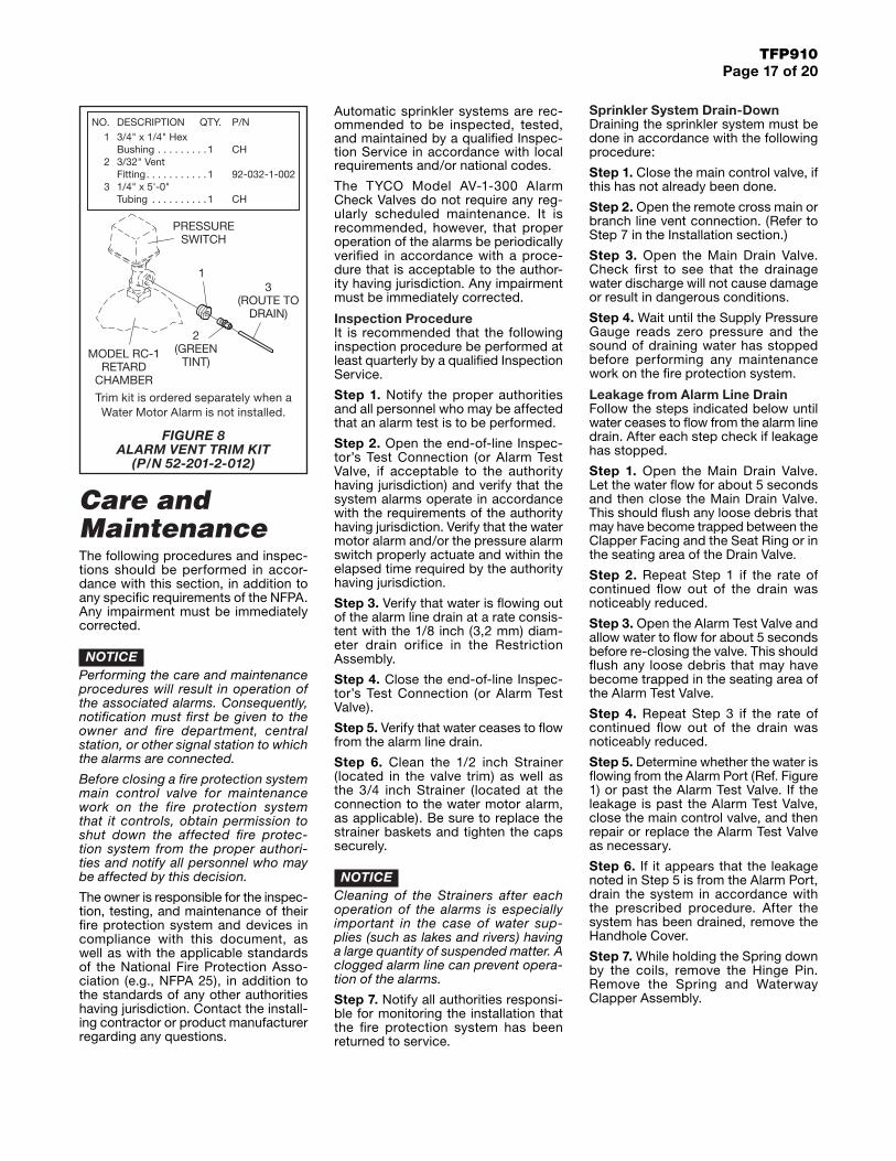
FIGURE 8 ALARM VENT TRIM KIT
(P/N 52-201-2-012)
Trim kit is ordered separately when a Water Motor Alarm is not installed.

TFP910Page 18 of 20
Step 8. Using a light, check for and remove any debris that may have become lodged within the Seat Ring groove. Inspect the Seat Ring seat for any damage. If the Seat Ring has become dented across the seat then the Alarm Check Valve will have to be replaced. It is impractical to re-face a Seat Ring in the field.
Step 9. Check for and remove any debris that may have become lodged in the Clapper Facing. If a minor imper-fection remains in the Clapper Facing, then turn it over after thoroughly clean-ing both surfaces with a clean cloth. Replace the Clapper Facing if neces-sary. Be sure to securely re-tighten the retaining fastener for the Clapper Washer.
Step 10. Replace the Spring and Waterway Clapper Assembly as shown in Figure 1. While holding the coils of the Spring down, re-insert the Hinge Pin. Be sure that the Hinge Pin is pushed all the way to the rear of the valve.
Step 11. Install Handhole Cover:
a. Align Handhole Cover Gasket and Handhole Cover in proper orien-tation with valve body (Ref. Figure 1) and hold in place
b. Apply LOCTITE No. 242 (or equiv-alent) to Hex Bolt threads
c. Insert Hex Bolts through Hand-hole Cover Gasket and Handhole Cover, hand-tighten into valve body
d. Using crossdraw sequence to assure uniformity, wrench-tighten Hex Bolts to appropriate torque values (Ref. Table C)
e. Inspect to assure all Hex Bolts are securely tightened
Step 12. Return the Alarm Valve to operation in accordance with the steps described in the Setting Procedure section.
Clogged Alarm Line DrainIf water either does not flow or only dribbles out of the alarm line drain during an alarm test, then it is likely that the screen protecting the Restric-tion Assembly drain orifice (Ref. Figure 3) has become clogged.
NOTICEFor variable pressure systems, a clogged alarm line drain will increase the likelihood of a false alarm.
First break the union downstream of the Drain Restriction and remove the Drain Restriction for cleaning by back-flushing the screen. Re-install the Drain Restriction and re-assemble the drain line.
Loss of Excess System PressureFor variable pressure systems, the System Pressure Gauge normally indi-cates a pressure greater than that shown by the Supply Pressure Gauge. Also, the value should be close to that of the peak supply pressure that has occurred after the system was placed in service.
NOTICEFor variable pressure systems, loss of excess system pressure will increase the likelihood of a false alarm.
Follow the procedure indicated below to correct a loss of excess system pressure condition.
Step 1. Check for signs of continued leakage from the alarm line drain. If rust stains and/or water deposits indicate that continued leakage has been taking place, take corrective action according to the procedure described in the sub-section entitled “Leakage from Alarm Line Drain.”
Step 2. If there are no signs of contin-ued leakage from the alarm line drain, close the main control valve, slowly remove the plug from the supply pres-sure gauge test valve to relieve the supply pressure, and then slowly open the union in the externally mounted bypass.
Step 3. Check for leakage past the Bypass Check Valve. If there is leakage, debris may have become lodged between its clapper and seat. Drain the system in accordance with the prescribed procedure and then clean or replace the Bypass Check Valve as required.
Step 4. Re-assemble the externally mounted bypass, replace the plug into the Gauge Test Valve, and return the fire protection system to operation in accordance with the steps described in the Operation section.
Step 5. If there are no signs of leakage past either the Alarm Check Valve Clapper per Step 1 or the Bypass Check Valve per Step 2, inspect the sprinkler system for leakage.
Excess Pressure Due to Thermal ExpansionWet pipe sprinkler systems subject to ambient temperatures in excess of 100°F (38°C) can experience signifi-cant increases in system pressure due to the thermal expansion of the water. In particular, a gridded wet-pipe system with a relatively small air pocket and no relief valve can be subjected to an increase of more than 100 psi (6,9 bar), due to an increase in ambient tempera-ture of approximately 50°F (28°C).
As necessary, install a pressure relief valve, in accordance with the require-ments of the authority having jurisdic-tion, to automatically relieve the excess pressure that could otherwise be created in wet-pipe systems exposed to significant increases in ambient temperature.
False AlarmsFollow the step below when repeated false alarms occur in a variable pres-sure system.
Step 1. Check for and correct the cause of continued leakage out the alarm line drain.
Step 2. Check for and clean a clogged alarm line drain.
Step 3. Check for and correct the cause of a loss in excess system pressure.
Step 4. Drain the sprinkler system and re-fill it using the steps described in the Setting Procedure section.
Intermittent AlarmsIf the pressure alarm switch gives a steady signal, but the water motor gen-erates an intermittent alarm, check for binding in the water motor alarm drive shaft.
If the water motor alarm and/or the pressure alarm switch provide an intermittent alarm, it is likely the con-sequence of an excessive amount of air being trapped within the sprin-kler system. Drain down the sprinkler system and refill it using the steps described in the Setting Procedure section.
A discontinuance of an alarm may also be caused by the Clapper closing due to a sudden drop in supply pressure or the shut-off of a pump in the supply line. These types of problems can only be corrected by maintaining a steady supply pressure.
Nominal Valve Sizes
Inches (DN)
Torque Feet Lbs.
(Nm)
2-1/2(DN65)
39 (52)
4(DN100)
39 (52)
6(DN150)
60 (80)
8(DN200)
120 (160)
TABLE C HANDHOLE COVER BOLTS
MAXIMUM TORQUE
TFP910Page 19 of 20
Limited WarrantyFor warranty terms and conditions, visit www.tyco-fire.com.
Ordering ProcedureContact your local distributor for avail-ability. When placing an order, indicate the full product name. Refer to Table A (Page 3) for Flange Drilling Speci-fications. The Price Book provides Part Numbers (P/Ns) for factory pre-trimmed Model AV-1-300 Valves.
Standard AV-1-300 Alarm Check Valve(Assumes American Standard Flange Drilling, American Threaded Ports, and American Groove Outside Diameter, as applicable.)
Specify: (size in inches) Model AV-1-300 Alarm Check Valve with (end con-nections), P/N (specify):
2-1/2 Inch Valves2.88 inch (73,0 mm) Groove O.D. x 2.88 inch (73,0 mm) Groove O.D.2-1/2 Inch G x G . . . . . . . . . . 52-203-1-110
ANSI Flange x 2.88 inch (73,0 mm) Groove O.D.2-1/2 Inch F x G . . . . . . . . . . . 52-203-1-210
4 Inch Valves4.50 inch (114,3 mm) Groove O.D. x 4.50 inch (114,3 mm) Groove O.D.4 Inch G x G . . . . . . . . . . . . . 52-203-1-113
ANSI Flange x 4.50 inch (114,3 mm) Groove O.D.4 Inch F x G . . . . . . . . . . . . . . 52-203-1-413
ANSI Flange x ANSI Flange4 Inch F x F . . . . . . . . . . . . . . 52-203-1-013
6 Inch Valves6.62 inch (168,3 mm) Groove O.D. x 6.62 inch (168,3 mm) Groove O.D.6 Inch G x G . . . . . . . . . . . . . 52-203-1-115
ANSI Flange x 6.62 inch (168,3 mm) Groove O.D.6 Inch F x G . . . . . . . . . . . . . . 52-203-1-615
ANSI Flange x ANSI Flange6 Inch F x F . . . . . . . . . . . . . . 52-203-1-015
8 Inch Valves8.62 inch (219,1 mm) Groove O.D. x 8.62 inch (219,1 mm) Groove O.D.8 Inch G x G . . . . . . . . . . . . . 52-203-1-916
ANSI Flange x 8.62 inch (219,1 mm) Groove O.D.8 Inch F x G . . . . . . . . . . . . . . 52-203-1-816
ANSI Flange x ANSI Flange8 inch F x F . . . . . . . . . . . . . . 52-203-1-016
AV-1-300 Valve TrimStandard OrderSpecify: Vertical, Closed Drain Galvanized Trim for (size) Model AV-1-300 Alarm Check Valve, P/N (specify):Vertical Closed Drain, Galvanized (See Figure 4)2-1/2 Inch . . . . . . . . . . . . . . . . . . . .52-204-4-9504 or 6 Inch* . . . . . . . . . . . . . . . . . . .52-204-4-951 8 Inch* . . . . . . . . . . . . . . . . . . . . . .52-204-4-952
*Provided semi-preassembledSpecial OrderSpecify: (Vertical or Horizontal), (Closed or Open) Drain Galvanized Trim for (size) Model AV-1-300 Alarm Check Valve, P/N (specify):Vertical Open Drain, Galvanized (See Figure 5)2-1/2 Inch . . . . . . . . . . . . . . . . . . . .52-204-4-0534 or 6 Inch* . . . . . . . . . . . . . . . . . . .52-204-4-954 8 Inch* . . . . . . . . . . . . . . . . . . . . . .52-204-4-955
*Provided semi-preassembled
Horizontal Closed Drain, Galvanized (See Figure 6)4 or 6 Inch . . . . . . . . . . . . . . . . . . .52-204-4-0578 Inch . . . . . . . . . . . . . . . . . . . . . . .52-204-4-058
AccessoriesOrder the following accessories, as applicable:
Model RC-1 Retard Chamber . . . . . . . . . . 52-211-1-002(Required for variable pressure water sup-ply conditions.)
Alarm Vent Trim . . . . . . . . . . . 52-201-2-012(Required when a water motor alarm is not installed.)
Model PS10-2 Potter Electric Waterflow Pressure Alarm Switch . . . . . . . . . . . 25710(Required for electric signal indicating waterflow.)
Model WMA-1 Water Motor AlarmRed Finish Gong . . . . . . . . . . . . .52-630-1-001PAluminum Finish Gong. . . . . . . . .52-630-2-001P(Required for a mechanical waterflow alarm.)
Optional 600 PSI Water Pressure Gauge . . . . . . . . . . 92-343-1-004
Replacement PartsValveSpecify: (description) for use with (size) Model AV-1-300 Alarm Check Valve, P/N (specify, see Figure 1)
TrimSpecify: (description) for use with Model AV-1-300 Alarm Check Valve, P/N (specify, see Figure 4, 5, or 6)
Other Model AV-1-300 Configurations
Other AV-1-300 Alarm Check Valves are valves ordered with any combina-tion of flange, threaded port, or groove outside diameter not offered under Standard AV-1-300 Alarm Check Valve offerings.
Valves with NPT threaded ports are intended for use with the AV-1-300 Valve Trim described in this data sheet. Valves with ISO threaded ports are intended for use with special order trim that is provided by local distributors to meet the specific needs of certain localities. Contact your local distribu-tor regarding valves and valve trim for specific localities.
Specify: (size) Model AV-1-300 Alarm Check Valve with (connections) with (NPT or ISO) threaded ports, P/N (specify):
2-1/2 Inch Valves with NPT PortsISO (PN16) Flange x 2.88 inch (73,0 mm)Groove O.D. . . . . . . . . . . . . . 52-203-1-251
ANSI Flange x 3.00 inch (76,1 mm)Groove O.D. . . . . . . . . . . . . . 52-203-1-220
ISO (PN16) Flange x 3.00 inch (76,1 mm)Groove O.D. . . . . . . . . . . . . . 52-203-1-331
AS Flange x 2.88 inch (73,0 mm)Groove O.D . . . . . . . . . . . . . . 52-203-1-611
AS Flange x 3.00 inch (76,1 mm)Groove O.D. . . . . . . . . . . . . . 52-203-4-410
JIS Flange x 2.88 inch (73,0 mm)Groove O.D. . . . . . . . . . . . . . 52-203-1-710
JIS Flange x 3.00 inch (76,1 mm)Groove O.D. . . . . . . . . . . . . . 52-203-1-810
3.00 inch (76,1 mm) Groove O.D x 3.00 inch (76,1 mm)Groove O.D. . . . . . . . . . . . . . 52-203-1-120
2-1/2 Inch Valves with ISO PortsISO (PN16) Flange x 2.88 inch (73,0 mm)Groove O.D. . . . . . . . . . . . . . 52-203-1-211
ISO (PN16) Flange x 3.00 inch (76,1 mm)Groove O.D. . . . . . . . . . . . . . 52-203-1-311
3.00 inch (76,1 mm) Groove O.D. x 3.00 inch (76,1 mm)Groove O.D. . . . . . . . . . . . . . 52-203-4-120
2.88 inch (73,0 mm) Groove O.D. x 2.88 inch (73,0 mm)Groove O.D. . . . . . . . . . . . . . 52-203-1-921
GLOBAL HEADQUARTERS | 1400 Pennbrook Parkway, Lansdale, PA 19446 | Telephone +1-215-362-0700
TFP910Page 20 of 20
Copyright © 2016 Tyco Fire Products, LP. All rights reserved.LOCTITE is a registered trademark of Henkel Corporation
4 Inch Valves with NPT PortsISO (PN16) Flange x 4.50 inch (114,3 mm)Groove O.D. . . . . . . . . . . . . . 52-203-1-493
ISO (PN16) Flange x ISO (PN16) Flange . . . . . . . . . 52-203-4-013
AS Flange xAS Flange . . . . . . . . . . . . . . . 52-203-4-313
AS Flange x 4.50 inch (114,3 mm)Groove O.D. . . . . . . . . . . . . . 52-203-4-413
JIS Flange xJIS Flange . . . . . . . . . . . . . . . 52-203-4-713
JIS Flange x 4.50 inch (114,3 mm)Groove O.D. . . . . . . . . . . . . . 52-203-4-813
4 Inch Valves with ISO PortsISO (PN16) Flange xISO Flange . . . . . . . . . . . . . . 52-203-4-113
ISO (PN16) Flange x 4.50 inch (114,3 mm)Groove O.D. . . . . . . . . . . . . . 52-203-4-213
4.50 inch (114,3 mm) Groove O.D. x 4.50 inch (114,3 mm)Groove O.D. . . . . . . . . . . . . . 52-203-1-923
6 Inch Valves with NPT PortsANSI Flange x 6.50 inch (165,1 mm)Groove O.D. . . . . . . . . . . . . . 52-203-1-625
ISO (PN16) Flange x 6.62 inch (168,3 mm)Groove O.D. . . . . . . . . . . . . . 52-203-1-695
ISO (PN16) Flange x 6.50 inch (165,1 mm)Groove O.D. . . . . . . . . . . . . . 52-203-5-215
ISO (PN16) Flange xISO (PN16) Flange . . . . . . . . . 52-203-4-015
AS Flange x AS Flange . . . . . . . . . . . . . . . 52-203-4-315
AS Flange x 6.62 inch (168,3 mm)Groove O.D. . . . . . . . . . . . . . 52-203-4-415
AS Flange x 6.50 inch (165,1 mm)Groove O.D. . . . . . . . . . . . . . 52-203-4-425
JIS Flange xJIS Flange . . . . . . . . . . . . . . . 52-203-4-715
JIS Flange x 6.62 inch (168,3 mm)Groove O.D. . . . . . . . . . . . . . 52-203-4-815
JIS Flange x 6.50 inch (165,1 mm)Groove O.D. . . . . . . . . . . . . . 52-203-5-815
6.50 inch (165,1 mm) Groove O.D. x 6.50 inch (165,1 mm)Groove O.D. . . . . . . . . . . . . . 52-203-1-124
6 Inch Valves with ISO PortsISO (PN16) Flange x ISO (PN16) Flange . . . . . . . . . 52-203-4-115
ISO (PN16) Flange x 6.62 inch (168,3 mm)Groove O.D. . . . . . . . . . . . . . 52-203-4-215
ISO (PN16) Flange x 6.50 inch (165,1 mm)Groove O.D. . . . . . . . . . . . . . 52-203-4-225
6.62 inch (168,3 mm) Groove O.D. x 6.62 inch (168,3 mm)Groove O.D. . . . . . . . . . . . . . 52-203-1-925
6.50 inch (165,1 mm) Groove O.D. x 6.50 inch (165,1 mm)Groove O.D. . . . . . . . . . . . . . 52-203-1-125
8 Inch Valves with NPT PortsISO (PN10) Flange x 8.62 inch (219,1 mm)Groove O.D. . . . . . . . . . . . . . 52-203-1-896
ISO (PN16) Flange x 8.62 inch (219,1 mm)Groove O.D. . . . . . . . . . . . . . 52-203-4-266
ISO (PN10) Flange xISO (PN10) Flange . . . . . . . . . 52-203-4-016
ISO (PN16) Flange xISO (PN16) Flange . . . . . . . . . 52-203-4-118
AS Flange xAS Flange . . . . . . . . . . . . . . . 52-203-4-316
AS Flange x 8.62 inch (219,1 mm)Groove O.D. . . . . . . . . . . . . . 52-203-4-416
JIS Flange xJIS Flange . . . . . . . . . . . . . . . 52-203-1-716
JIS Flange x 8.62 inch (219,1 mm)Groove O.D. . . . . . . . . . . . . . 52-203-4-816
8 Inch Valves with ISO PortsISO (PN10) Flange xISO (PN10) Flange . . . . . . . . . 52-203-4-116
ISO (PN16) Flange xISO (PN16) Flange . . . . . . . . . 52-203-4-117
ISO (PN10) Flange x 8.62 inch (219,1 mm)Groove O.D. . . . . . . . . . . . . . 52-203-4-216
ISO (PN16) Flange x 8.62 inch (219,1 mm)Groove O.D. . . . . . . . . . . . . . 52-203-4-226
8.62 inch (219,1 mm) Groove O.D. x 8.62 inch (219,1 mm)Groove O.D. . . . . . . . . . . . . . 52-203-1-926
![Untitled-2 [ ] · PDF fileface to face and end to end dimensions ansi .10- 1973 depth groove regular standard facings basic flange-edge to flange edge face-to-face dimension gwen in](https://img.dokumen.tips/doc/110x75/5a79c7ae7f8b9ab05f8c47f7/untitled-2-to-face-and-end-to-end-dimensions-ansi-10-1973-depth-groove-regular.jpg)