Embed Size (px)
Citation preview

Model ISC40 Inductive Conductivity sensor and fittings
The model ISC40 sensors are designed for use with the EXA: ISC202g(S) 2-wire transmitters and the EXA: ISC450G 4-wire analyzers. This combination exceeds all expectations for conductivity measurement in terms of: reliability, accuracy, rangeability and price performance.
The accuracy is 0.5% of reading plus 0.5 uS/cm for any conductivity value: whether measured in rinse water or in concentrated acids. The materials of construction guarantee a long life under harch industrial conditions:- The erosion/abrasion resistant PEEK (Poly Ether Ether Ketone),
which also features excellent chemical resistance in all solutions except fluoric acid or oxidizing concentrated acids.
- The ultimate material in terms of chemical resistance: PFA for applications in hydrofluoric acid and oxidizing concentrated acids (nitric, sulfuric, oleum).
The PEEK sensor is provided with a rugged Stainless Steel mounting thread, nut and gasket combination for ultimate flexibility in installation using bulk head installation technique. There is also a wide range of holders and options available for reliable in-line or off-line installation with double O-ring seals for long service life of the sensor. Additional models are available for use in Ball-Valve Insertion applications and in Sanitary Flange installations.
The PFA sensor comes with an integral lap-joint flange, because in applications, where this sensor is used, it is very difficult to find O-rings that are resistant to the process.
Both sensors have a large bore for optimal resistance to fouling processes and when properly installed, the flow will keep the sensor clean preventing measuring errors.
GeneralSpecifications
System Configuration
Sensors Cables Fittings Transmitters AccessoriesSensors Cables Fittings Transmitters AccessoriesSensors Cables Fittings Transmitters Accessories
Features and Applications• Inductive Conductivity technique for elimination of fouling and
polarization errors.• Wide bore sensors for long term stability.• Installation flexibility by wide range of holders and by the use of
universal bulkhead construction.• Wide rangeability in terms of conductivity (1 µS/cm to 2 S/cm)
and temperature (-20 to 130ºC).• All applications where severe electrode fouling prevents the use
of contacting electrodes.• All ranges except the (ultra) pure water applications.• All slurry applications where conventional systems suffer from
plugging or erosion.• All applications where the 6 decade rangeability is necessary
for accurate process control.
GS 12D8J2-E-E11th Edition

2
Actual installed cell-constant as function of spacing around the sensor.
General SpecificationsModel ISC40 Inductive conductivity sensorA. Compatibility : ISC40G is suitable for use with
both ISC450G and I(S)C202G(S) inductive conductivity transmitter.
B. Hazardous area : ISC40S is suitable for use with the I(S)C202S conform to ATEX, FM and CSA intrinsic safety standards
- atex intrinsic safety : II 1 G EEx ib [ia] IIC T6 for ambient temp. -10 to 40°C
: II 1 G EEx ia [ia] IIC T4 for ambient temp. -10 to 55°C
- atex certificate no. : KEMA 00 ATEX 1067 X - FM intrinsic safety : IS CL1, DIV1, GP ABCD T3B
for ambient temp. (ta) -10°C to 55°C and T4 for ambient temp. (ta) -10°C to 40°C.
- FM approval report : J.L. 1Y1A7.AX - CSA intrinsic safety : Ex [ia] Class I, Division 1, Groups C
and D, T4a - CSA approval file : LR 102851-1 C. Measuring range : 0- 2000 mS/cm at actual process
temperatures. The sensor has an error of 0.5 µS/cm (PEEK sensors) or 1 µS/cm (PFA sensor) that must be considered when application range is chosen.
D. Installation factor : Cellconstant: The nominal cell constant of the sensor is 1.88/cm for the PEEK sensor types and 3.00/cm for the PFA sensor. The calibrated values are indicated on the cable markers and the actual installation can change this factor. If there is less than 25 mm spacing between sensor and holder, in-situ calibration is necessary to meet the specified accuracies. An indication is given in figure.
D
non conductivepiping
conductivepiping
D i n m i l l i m e t e r s
0 10 20 30 40 50
0.90
Co
rre
ctio
n f
acto
r (x
no
min
al C
.C.)
0.95
1.30
1.25
1.20
1.00
1,05
1.10
1.15
E. Process temperature range Peek : -20 to 130ºC (0 to 270 °F) for
Response time 5 min. (90%) PFA : -20 to 100ºC (0 to 212 °F)
Response time 10 min. (90%)
F. Process pressure Peek : Maximum 20 bar (300 psi)
dependant on installation.
PFA : ºC ºF ºC ºF 100 212 20 36 BAR (PSI) 5 71 10 142
G. Materials - Sensor wetted parts : Victrex PEEK
(Poly-Ether-Ether-Ketone) : PFA
(High purity Perfluoro alkoxy alkane) - Sealing gasket : Viton for PEEK : Gore tex for PFA - Process adapters : AISI 316 SS, PVC or PVDF
(only for PEEK)
H. Process connection : Process connection are made in combination with a variety of adapters and fittings. See relevant sections in this document.
I Cables - Connection cable : Integral connection cable in a
variety of lengths up to 20 meter. - Extension cable : Extension cable with WF10 junction
box BA10 can be used to a total of 50 meters (fixed cable and extension cable).
J. Shipping details - Package - 3-5 meters : WxHxD = 350x270x50 mm - 10-20 meters : WxHxD = 320x240x110 mm - Packed weight approx. - 03 m : 1.0 kg - 05 m : 1.3 kg - 10 m : 1.6 kg - 15 m : 2.1 kg - 20 m : 2.5 kg - protection hose : 0.8 kg (approx.)
Only for PEEK
GS 12D8J2-E-E

D
k
FLANGE ADAPTER dl
116
(4.5
6)
O-ring
26.57 x 3.53
40.64 x 5.33
B
3
Flange adapter for -GG sensor
DIMENSIONS mm (inches)
Flange Adapters for -GG sensor
d D1 D2 Material/SFA Ø 19 (0.75) 121 (4.75) 152 (6.0) SS/SFD Ø 18 (0.71) 125 (5.00) 165 (6.5) SS
GS 12D8J2-E-E
nut G3/4viton gasket
Ø40 (1.57")
182
(7.1
6")
124
(4.8
8")
Minimum holeto fit sensorthrough: Ø48 (1.89")
Ø47 (1.85")
Unit: mm (inches)
O-rings spare parts for ISC40 sensor & Options as spare parts
O-ring material Dimensions EPDM Viton Silicon KALREZ QuantityO-rings for option /SFA /SFD40.64 x 5.33 / 26.57 x 3. 53 K1500CA K1500CB K1500CC 5 sets of 2 O-ringsO- rings for K1541KC (/S2W)40.87 x 3.53 / 26.57 x 2.62 K1541ZH K1500DJ K1500DK 2 sets of 3 O-rings2” seal-clampO- rings for K1541KB (/STW)º40.87 x 3.53 / 26.57 x 2. 62 K1541ZK K1500DL K1500DM 2 sets of 3 O-rings3” seal-clampO-rings for old modelsViton gasket K1500AM 5 O-rings
ISC40G(S)-GG Model
Dimensions
according ISO 2852
Partno. DescriptionK1541KB 3” Triclamp (STW) (ISO 2852)K1541KC 2” Triclamp (S2W) (ISO 2852)
Note: clamp not included
Model Suffix Option DescriptionISC40G General purpose inductive
conductivity sensorISC40S Intrinsically safe inductive
conductivity sensorSensor type -GG Glass filled PEEK, general modelTemperature -T1 Pt1000 sensor -T3 30k thermistor,
for IC200 select only T3Cable length -03 03 meter -05 05 meter -10 10 meter -15 15 meter -20 20 meterOptions for Sensor Material Proc.ConnectionFlange adapters -GG /SFA AISI 316 SS 2” ANSI 150 lbs /SFD AISI 316 SS NW50-PN16 /STW AISI 316 SS 3” tri-clamp /S2W AISI 316 SS 2” tri-clampCertificates /M Material certificate Not for -GR /Q Quality certificate
Adapters for ISC40G(S)-GG

4
GS 12D8J2-E-E
Fittings for ISC40G(S)-GGInductive Conductivity Sensors
For liquid analysis, the sensors are frequently mounted in either a flow or an immersion fitting. Yokogawa suppllies for the model ISC40 inductive conductivity sensors a full range of fittings with particular emphasis on designs that reduce installation and maintenance time and consequently save operation costs.
A wide choice of construction materials gives the user the optimal solution for any process considering chemical resistance, pressure and temperature specifications.
The flow fittings are used for installation of the sensors in sample by-pass lines. This makes maintenance easy without having to interrupt the main process stream. The subassemblies simplifies mounting of the sensors direct into process lines or vessels.This is particularly important where sample lines give problems, for instance with settling slurries.
Features• Wide choice of construction materials.• Built in drain on stainless steel flow fitting.• Quick disconnect direct insertion sub assemblies.• High temperature PVC immersion fitting with optional flanged
process connection for adjustable insertion depth.• High pressure and temperature specifications.• Electrolytically polished stainless steel fittings for optimal
corrosion resistance.
Ø 10 (4.0)
1/2
NPT
(150
)
97 (3
.9)
39 (1
.6)
120 (4.8)
1/2 NPT (150)
1/2 NPT (150)
Ø 54 (2.2)
1/2 NPT (150)
1/2 NPT (150)
158
(6.3
)
70 (2.8)
70 (2
.8)
186
(7.3
)
ø90(3.54)[72(2.83)]
27(1.06)
127
(5)
k D
dg
ø dg
ø k
ø D
L2
L1
58
L1
Hole pattern for mounting set (Option /MS or /MP)
Unit: mm (inches)
Model ISC40FF Flow fittingA. Process temperature - Model ISC40FF-S : Maximum 150ºC (300°F) - Model ISC40FF-P : Maximum 100ºC (210°F) - Model ISC40FF-F : Maximum 130ºC (270°F)B. Process pressure - Model ISC40FF-S : Max. 1.0 MPa (150 psi) at 150ºC (300 °F) - Model ISC40FF-P : Max. 0.6 MPa (90 psi) at 20°C (70°F)
Max. 0.1 MPa (15 psi) at 100°C (210°F) - Model ISC40 FF-F : Max. 1.0 MPa (150 psi) at 20°C (70°F)
Max. 0.1 MPa (15 psi) at 120°C (250°F) C. Wetted materials - Model ISC40FF-S : AISI 316 Stainless Steel - Model ISC40FF-P : Polypropylene - Model ISC40FF-F : PVDF (KYNAR®) Non-wetted materials - Nut : AISI 304 stainless steel. - Mounting set : AISI 304 Stainless Steel (optional) - Flange adapters : AISI 304 Stainless Steel (optional)
Dimensions
ISC40FF-PISC40FF-F
ISC40FF-S
Adapter dimensions
L1 L2 L3FP1 - FF1 161 216FP2 - FF2 151 206FP3 - FF3 163 218FP4 - FF4 149 204FS1 278 112FS2 298 122FS3 274 110FS4 298 122
Flange dimensions
D k dgDN25 ø115 ø85 ø13.51 Inch ø108 ø79.2 ø15.71/2 Inch ø88.7 ø66.6 ø15.7DN15 ø95 ø65 ø13.5
Panel dimensions
100x100, holes 70x70 ø10mm
5
GS 12D8J2-E-E
Model and Suffix Codes Model and Suffix Codes
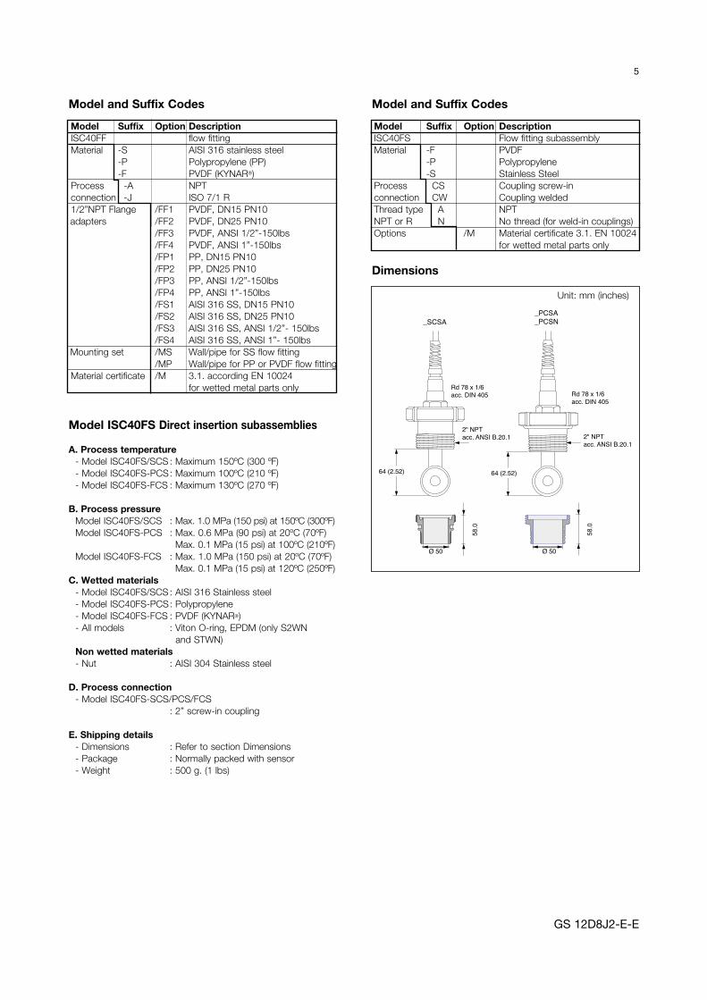
Model ISC40FS Direct insertion subassemblies
A. Process temperature - Model ISC40FS/SCS : Maximum 150ºC (300 ºF) - Model ISC40FS-PCS : Maximum 100ºC (210 ºF) - Model ISC40FS-FCS : Maximum 130ºC (270 ºF)
B. Process pressure Model ISC40FS/SCS : Max. 1.0 MPa (150 psi) at 150ºC (300ºF) Model ISC40FS-PCS : Max. 0.6 MPa (90 psi) at 20ºC (70ºF)
Max. 0.1 MPa (15 psi) at 100ºC (210ºF) Model ISC40FS-FCS : Max. 1.0 MPa (150 psi) at 20ºC (70ºF)
Max. 0.1 MPa (15 psi) at 120ºC (250ºF)C. Wetted materials - Model ISC40FS/SCS : AISI 316 Stainless steel - Model ISC40FS-PCS : Polypropylene - Model ISC40FS-FCS : PVDF (KYNAR®) - All models : Viton O-ring, EPDM (only S2WN
and STWN) Non wetted materials - Nut : AISI 304 Stainless steel
D. Process connection - Model ISC40FS-SCS/PCS/FCS
: 2” screw-in coupling
E. Shipping details - Dimensions : Refer to section Dimensions - Package : Normally packed with sensor - Weight : 500 g. (1 lbs)
64 (2.52)
2" NPTacc. ANSI B.20.1
64 (2.52)
Rd 78 x 1/6acc. DIN 405
Ø 50Ø 50
2" NPTacc. ANSI B.20.1
Rd 78 x 1/6acc. DIN 405
58.0
58.0
_SCSA_PCSA_PCSN
Unit: mm (inches)
Model Suffix Option DescriptionISC40FS Flow fitting subassemblyMaterial -F PVDF -P Polypropylene -S Stainless SteelProcess CS Coupling screw-inconnection CW Coupling weldedThread type A NPTNPT or R N No thread (for weld-in couplings)Options /M Material certificate 3.1. EN 10024
for wetted metal parts only
Model Suffix Option DescriptionISC40FF flow fittingMaterial -S AISI 316 stainless steel -P Polypropylene (PP) -F PVDF (KYNAR®)Process -A NPTconnection -J ISO 7/1 R1/2”NPT Flange /FF1 PVDF, DN15 PN10
adapters /FF2 PVDF, DN25 PN10 /FF3 PVDF, ANSI 1/2”-150lbs /FF4 PVDF, ANSI 1”-150lbs /FP1 PP, DN15 PN10 /FP2 PP, DN25 PN10 /FP3 PP, ANSI 1/2”-150lbs /FP4 PP, ANSI 1”-150lbs /FS1 AISI 316 SS, DN15 PN10 /FS2 AISI 316 SS, DN25 PN10 /FS3 AISI 316 SS, ANSI 1/2”- 150lbs /FS4 AISI 316 SS, ANSI 1”- 150lbs
Mounting set /MS Wall/pipe for SS flow fitting /MP Wall/pipe for PP or PVDF flow fitting
Material certificate /M 3.1. according EN 10024 for wetted metal parts only
Dimensions

6
GS 12D8J2-E-E
Model ISC40FD Immersion fittingA. Process temperature : Max. 80ºC (180 ºF) PVC : Max. 150ºC (300 ºF)
AISI 316 Stainless steelB. Process pressure - PVC : Max. 0.2 MPa (30 PSI) at
20ºC (70ºF) Max. 0.1 MPa (15 PSI) at 80ºC (180ºF)
- AISI316 Stainless steel : 10 barC. Wetted materials - Probe tube : C-PVC - Process sealing O-ring : Viton - Flange : PVC (Optional) Non wetted materials - Cable insulation : Thermoplastic rubberD. Process connection : - Adjustable flange : Hole pattern according to DIN
DN50-PN10 and ANSI 2” 150 lbs. Only for the PVC (Optional).
- Mounting set : Galvanized steel (Optional).
Note: Adjustable flange (/FA) is only for the PVC fitting
Immersion fitting
ø50 (1.97”)
114(4.49)
Pipe &Sensorlength
L
Model and Suffix Codes
2" Handrail
Guide pipe
Ø 48.6 x 500
(Ø 1.9 x 20")
Min: 110 (4.35")Max: 415 (16.34")
Immersion fitting
Ø 60 (2.36")
L
Ø 50 (2.0)
12
5 (
5)
42
(1
.65
)
Adjustableflange
Model Suffix Option Descriptioncode codeISC40FD Immersion fittingMaterial -S AISI 316 Stainless steel -V PVC-CPipe - Between 05 to 20 meterlength Example: 05 = 0.5 mFlange -NFL No flange -SFA AISI316 SS 2” -SFD AISI316 SS DN50Options /MS1 Pipe mounting set (Carbon
steel) /FA Adjustable flange with DIN
DN50-PN10 and ANSI 2” 150 lbs hole pattern (only for PVC)
/PH5 Protection hose for 5 m cable /PH10 Protection hose for 10 m cableMaterial certificate /M 3.1. according EN 10204
(for wetted metal parts only)
* The Immersion fitting is delivered without sensor. * The Immersion fitting is delivered without sensor.
DimensionsISC40FD-S (SS)*
Unit: mm (inches)Dimensions ISC40FD-V (PVC-C)*Immersion fitting & mounting set (Option /MS1)

7
GS 12D8J2-E-E
Partno. Flanges DescriptionK1500HG DN80 PN10 T-Piece, DN80 FlangeK1500HF DN100 PN10 T-Piece, DN100 FlangeK1500HP DN65 Gore-Tex seal for ISC40-TF (DN50)
C
øB øA
DN65 PN10
100.
0
300.0
Innerside of T-Piece islined with PFAThickness: 4mm
DN
80 P
N10
/ D
N10
0 P
N10
Unit: mm (inches)
Packaging size : 325 x 240 x 250 weight : 19.23 kg
A B CDN65 PN10 185 145 4 ø18DN80 PN10 200 160 8 ø18DN100 PN10 220 180 8 ø18
Mounting flange and bolts are included12
4.5
(4.9
")56
(2.2
")
Ø 1
00 (3
.94)
189.
5 (7
.46"
)
Ø 6
1 (2
.4)
G 3/4"
Ø50 (1.97")
Minimum holeto fit sensorthrough: Ø50 (1.97")
ISC40-TF Unit: mm (inches)Model and Suffix Codes
Model Suffix Option DescriptionISC40G-TF General purpose, PFA,
flange modelISC40S-TF Intrinsically safe, PFA,
flange modelTemperature -T1 Pt1000sensor Cable -03 03 mtrlength -05 05 mtr
-10 10 mtr -15 15 mtr -20 20 mtr
Protection hose /PH 03m, 05m, 10m, 15m, 20mfor -TF sensor (the same length as the cable)Certificates /M Material certificate (only apply to
SS316 wetted part) /Q Quality certificate
Option Description Part No./PH03 03 meter protection hose K1500DN/PH05 05 meter protection hose K1500DP/PH10 10 meter protection hose K1500DQ/PH15 15 meter protection hose K1500DR/PH20 20 meter protection hose K1500DS
ISC40G(S)-TF Model
T-Piece ISC40-TF
T-Piece for ISC40-TF Inductive Conductivity sensor

For mountingin SFT, STC 1 andSTC 2 Fittings.
Ø20 (0.78")
193
(7.6
0")
77 (3
.0")
Stainless steel
Peek
Minimum holeto fit sensorthrough: Ø48 (1.89")
Ø47 (1.85")
8
GS 12D8J2-E-E
ISC40-GS Unit: mm (inches)
ISC40G(S)-GS Model
123
(4.8
4")
Ø71 (2.80")
19 (0.75")
72 (2
.83"
)
134,
3 (5
.30"
)57
,3 (2
.25"
)
O-ring18.72 x 2.62
O-ring18.72 x 2.62
O-ring18.72 x 2.622” clamp steal
Tuchenhage Sanitary 2” Tri-clamp Tri-clamp complete
/SFT /STC1 /STC2
Options for the ISC40-GS (/SFT, /STC1, /STC2)
Options for -GS Sensor
Unit: mm (inches)
For mounting inISC40PRretractable fitting
Minimum holeto fit sensorthrough: Ø48 (1.89")
Ø47 (1.85")
45 (1.77")
Ø17 (0.67")
m19 x 1.5
Unit: mm (inches)ISC40-GR
ISC40G(S)-GR Model
Model and Suffix Codes
Model Suffix Option DescriptionISC40G-GR General purpose, glass filled
PEEK, retractable modelISC40S-GR Intrinsically safe, glass filled
PEEK, retractable modelTemp. sensor -T1 Pt1000
Cable length -03 03 mtr -05 05 mtr -10 10 mtr -15 15 mtr -20 20 mtr
Certificates /M Material certificate (only applies to SS316 wetted part)
/Q Quality certificate
Model and Suffix Codes
Model Suffix Option DescriptionISC40G-GS General purpose, glass filled PEEK,
shaft modelISC40S-GS Intrinsically safe, glass filled PEEK,
shaft modelTemp. sensor -T1 Pt1000Cable length -03 03 mtr
-05 05 mtr -10 10 mtr -15 15 mtr -20 20 mtr
Flange adapters /SFT1 AIS316 SS Sanitary Tuchenhagenfor -GS sensor /STC1 AIS316 SS Sanitary 2” Tri-clamp* /STC2 AIS316 SS Tri-clamp*
Certificates /M Material certificate (only applies to SS316 wetted part)
/Q Quality certificate
* according to ISO 2852

General SpecificationsA. Materials: Wetted parts Model ISC40PR-S (Stainless steel) Stainless steel AISI 316 -Probe Stainless steel AISI 316 -O-ring seals Viton 70° shore
Model ISC40PR-T (Titanium) Titanium Grade 2 or 3 -Probe Titanium Grade 2 or 3 -O-ring seals Viton 70° shore Non-wetted parts -Stainless steel (AISI 316) and polyphenylene sulphide (PPS)
B. Insertion length The probe length can be adjusted to a maximum of either 0.5
or 1 meter. The actual probe insertion length depends on the use of optional adapters and/or ball valves.The dimensional drawing indicates the maximum insertion length for both specified probe lengths.
C. Pressure / temperature ratings - Static conditions 2 MPa at 20ºC
500 kPa at 130ºC - Operating conditions maintenance max. 500 kPa
max. 130ºC - Flange ratings DIN flange DN50 PN16
ANSI flange 2” 150 lbs
D. Weight Approx 2.5 kg. (stainless steel version without ball-valve and adapters)
Retractable fitting for ISC40PR for Inductive Conductivity sensor
The ISC40PR retractable fitting can be applied in all processes where it is necessary to remove the sensor without interrupting the process. The Yokogawa design ensures the safe retraction of the sensor from the process without requiring a shut-down.
The optional adapters make selection of a suitable installation easy. The flanged connection is available in DIN or ANSI version. The threaded connections are available in R2 or 2” NPT.When inserted, the probe can be locked at any position (between the minimum and maximum) with a locking ring. In addition, the optional drain port makes it possible to relieve the pressure before complete disassembly.
The choice between stainless steel and titanium (as construction materials) makes use in many applications possible.
Yokogawa recommends using the sensor ISC40 -GR- - . For model code see page 8. For safety reasons Yokogawa recommends to use a flanged ball-valve.
Features• Adjustable insertion depth for optimal positioning in the
process.• Easy cleaning of the sensor.• Damped probe retraction by o-ring friction with pressurized
systems.• Adaptable to most installations by a range of options.• Optional drain port for relieving pressure, prior to extraction.
External Dimensions
9
GS 12D8J2-E-E
500 or 1000 (19.70 or 39.37)
282
(11.
10)
max. 345 or 845 (13.58 or 33.26)
ISO 228/1-G2
130 (5.21)
min.150 (5.9)
max.130 (5.11)
max.170 or 670
(6.69 or 26.4)
min. 150 (5.9)
(NW50 (150mm or 5.9")(2" ANSI (180mm or 7.08")
max. (NW50)120mm or 620(4.72 or 24.4)
max.130 (5.11)
(2") 90mm or 590(3.54 or 23.22)
Unit: mm (inches)
* Drawn dimensions are for stainless steel ball valves. They may differ slightly when titanium ball valves are used.
Note: Bolts, nuts and gaskets are not included

10
Options /A, /B, /E, /F Options /C, /G Options /D, /H
ISO 228/1-G2
77 (3
")1/8-27 NPT
UNIVERSAL FLANGE
Flange DN50 PN16ANSI Flange 2" 150 lbs
ISO 228/1-G2
54 (2
.12"
)
UNIVERSAL FLANGE
Flange DN50 PN16ANSI Flange 2" 150 lbs
ISO 228/1-G2
ISO 7/1-R2or
2 -11.5 NPT
Options for -PR Sensor
Unit: mm (inches)
GS 12D8J2-E-E
Model and Suffix Codes
Model Code Suffix Code Option Code DescriptionISC40PR Retractable Fitting, 2” BSP-femaleMaterial -S Stainless steel AISI 316 -T Titanium Grade 2 or 3Probe -05 0.5 mlength -10 1.0 m /A Adapter R2-G2 (SS AISI 316) /B Adapter 2” NPT-G2 (SS AISI 316) /C Flange adapter (SS AISI 316) /D Flange adapter for drain (SS AISI 316) /E Adapter R2-G2 (Titanium Grade 2 or 3) /F Adapter 2” NPT-G2 (Titanium Grade 2 or 3) /G Flange adapter (Titanium Grade 2 or 3) /H Flange adapter for drain (Titanium Grade 2 or 3) /M Material certificate 3.1.B according to EN 10 204 (DIN 50 049) (on wetted parts) /T Test certificate for hydrostatic pressure test (2 MPa at ambient temperature) /J Ball valve R2 (SS AISI 316) /K Ball valve 2” NPT (SS AISI 316) /L Ball valve 2” ANSI Flanged (SS AISI 316) /N Ball valve DN 50 PN16 Flanged (SS AISI 316)
Table 1. Titanium Ball valves
Model Option DescriptionBV40 Titanium ball valve 1” (25 mm) /P 2”BSPT /Q 2” NPT female + adapter /R 2” ANSI flanged /S DN50 PN16 flanged

11
GS 12D8J2-E-E
Material
PVDF S.S. 316 VITON PEEK PP PVC PFA (Kynar)
Sulfiric acid 10 O O O X X X O O O O O O O O O X O O O 50 O O O X X X O O O O O X O O O O O O O 95 O X - X X X O O O - - - X - X X O O O fuming - - - - - - O O O - - - - - - - O O OHydrochloric acid 10 O O O - - - O O O O O X O O OX O O O sat. O O O - - - O O X O O O O O O ONitric acid 25 O O X X X X O O X O O O O O O X O O O 50 O O X X X X - - - X X X X - O X O O O 95 O X - O O O - - - - - - - - - - O O O fuming - - - O O O - - - - - - - - - - O O OPhosphoric acid 25 O O O - - - O O O O O O O O O X O O O 50 O O O X X X O O O O O O O O O O O O O 95 O O O O O O X X - O O O O O O O O O OHydrofluoric acid 40 O O O - - - O O O - - - O O OX O O O 75 O O O - - - O O O - - - O O XX O O OAcetic acid 10 O O O O O X - - - O O O O O O X O O O glacial O X - O O X - - - O O X O X X X O O OFormic acid 80 O O O X X X - - - X X X O O O - O O XCitric acid 50 O O O O O O O O O O O O O O O O O O OCalcium hydroxide sat. O O O O O O O O O O O O O O O O O O OPotassium hydroxide 50 O O X O O O O O O O O O O O O O O O OSodium hydroxide 40 O O X O O O X X X O O O O O O X O O OAmmonia in water 30 O O O O O O X X X O O O O O O X O O OAmmonium chloride sat. O O O X X X O O O O O O O O O O O O OZinc chloride 50 O O O X X X O O O O O O O O O O O O OIron (III) chloride 50 O O O - - - O O O O O O O O O O O O OSodium sulfite sat. O O O O O O - - - O O O O O O O O O OSodium carbonate sat. O O O O O O O O O O O O O O O O O O OPotassium chloride sat. O O O X X X O O O O O O O O O O O O OSodium sulfate sat. O O O O O O O O O O O O O O O O O O OCalcium chloride sat. O O O X X X O O O O O O O O O O O O OSodium chloride sat. O O O X X X O O O O O O O O O O O O OSodium nitrate 50 O O O X X X O O O O O O O O O O O O OAluminium chloride sat. O O O - - - O O O O O O O O O O O O OHydrogen peroxide 30 O O O O O O O O O O O O O O O O O O OSodium hypochloride 50 O O O X X X O O X O O O X X X X O O OPotassium dichromate sat. O O O O O O O O O O O O O O O O O O OChlorinated lime O X - X X X X X X - - O O O O OEthanol 80 O O X O O O X - - O O O O O O X O O OCyclohexane O O X O O O O O O O O O - - O O O O OToluene O O O O O O - - - O O O X - - - O O OTrichloroethane X X X O O X X X X O O O - - - - O O OWater O O O O O O O O O O O O O O O O O O O
20 60 100
20 60 100
20 60 100
20 60 100
20 60 20 60
Inor
gani
c ac
idO
rgan
ic
acid
Alk
ali
Aci
dsa
ltN
eutr
alsa
ltO
xidi
zing
agen
tO
rgan
icso
lven
t
Temp.
ºC%Conc.
Bas
icsa
lt
O = can be used, X = shortens useful life, - = cannot be used
Note: Information in this list is based on our general experience and literature data and given in good faith. However Yokogawa is unable to accept responsobility for claims related to this information.
20 60 100
Chemical Compatibility Chart

GS 12D8J2-E-ESubject to change without noticeCopyright©
Printed in The Netherlands, 11-705 (A) I
YOKOGAWA EUROPE B.V.Databankweg 203821 AL AMERSFOORTThe NetherlandsTel. +31-33-4641 611Fax +31-33-4641 610www.yokogawa.com/eu
YOKOGAWA CORPORATION OF AMERICA2 Dart RoadNewnan GA 30265United StatesTel. (1)-770-253-7000Fax (1)-770-251-2088www.yokogawa.com/us
YOKOGAWA ELECTRIC ASIA Pte. Ltd.5 Bedok South RoadSingapore 469270SingaporeTel. (65)-241-9933Fax (65)-241-2606www.yokogawa.com/sg
YOKOGAWA HEADQUARTERS9-32, Nakacho 2-chome,MusashinoshiTokyo 180JapanTel. (81)-422-52-5535Fax (81)-422-55-1202www.yokogawa.com
Yokogawa has an extensive sales and distribution network. Please refer to the European website (www.yokogawa.com/eu) to contact your nearest representative.