Embed Size (px)
Citation preview
Written by Seidl M Edwards M Guy I and Appleby J (TRL Ltd) June ndash 2020
General Safety Regulation - Technical study to assess and
develop performance
requirements and test protocols for various
measures implementing the new General Safety
Regulation for accident avoidance and vehicle
occupant pedestrian and
cyclist protection in case of collisions
Intelligent Speed Assistance (ISA) Second Interim
Report ndash Detailed development of requirements and
tests
EUROPEAN COMMISSION
Directorate-General for Internal Market Industry Entrepreneurship and SMEs
Directorate C mdash Industrial Transformation and Advanced Value Chains Unit C4 mdash Automotive and Mobility Industries
Contact Peter Broertjes
E-mail GROW-C4eceuropaeu
European Commission B-1049 Brussels
EUROPEAN COMMISSION
Directorate-General for Internal Market Industry Entrepreneurship and SMEs
General Safety Regulation - Technical study to assess and
develop performance
requirements and test protocols for various
measures implementing the
new General Safety Regulation for accident avoidance and vehicle
occupant pedestrian and cyclist protection in case of
collisions
Intelligent Speed Assistance (ISA) Second Interim
Report ndash Detailed development of requirements and
tests
EUROPEAN COMMISSION
Directorate-General for Internal Market Industry Entrepreneurship and SMEs
LEGAL NOTICE
This document has been prepared for the European Commission however it reflects the views only of the authors and the Commission cannot be held responsible for any use which may be made of the information contained therein
More information on the European Union is available on the Internet (httpwwweuropaeu)
Luxembourg Publications Office of the European Union 2020
copy European Union 2020
Image(s) copy TRL 2020 (UNLESS OTHERWISE SPECIFIED)
Europe Direct is a service to help you find answers
to your questions about the European Union
Freephone number ()
00 800 6 7 8 9 10 11
() The information given is free as are most calls (though some operators phone boxes or hotels may charge you)
Disclaimer
This report has been produced by the Transport Research Laboratory under a contract with the European Commission Any views expressed in this report are not necessarily those of the European Commission The information contained herein does not necessarily reflect the views or policies of the customer for whom this report was prepared Whilst every effort has been made to ensure that the matter presented in this report is relevant accurate and up-to-date TRL Limited cannot accept any liability for any error or omission or reliance on part or all of the content in another context Framework Contract No 121PP2011FC Specific Contract No SI2791480 Document number CPR2792 Prepared By TRL Ltd Quality approved Anna George (Project Manager) Mervyn EdwardsDavid Hynd (Technical Referees)
GSR ISA second interim report
June 2020 6
EXECUTIVE SUMMARY
Intelligent Speed Assistance (ISA) means a system to aid the driver in maintaining the
appropriate speed for the road environment by providing dedicated and appropriate
feedback
The revised General Safety Regulation (EU) 20192144 has entered into force and will
help ensure the deployment of new advanced safety features with high potential of
saving lives on EU roads One of a package of measures to be implemented within this
revision is the mandatory fitment of ISA to passenger cars vans trucks buses and
coaches
The objective of the ISA work package was to develop draft technical annexes setting out
requirements and test procedures for secondary type approval legislation for regulatory
ISA systems for vehicle categories M1 M2 M3 N1 N2 and N3 This work package was
divided into the following tasks
bull Task 1 Review and scope contents of draft technical annexes
bull Task 2 Detailed development of requirements and tests
bull Task 3 Trials of track-based test procedures
bull Task 4 Consultations liaison
bull Task 5 Reporting meetings and ad-hoc support
Task 1 and part of Task 4 were completed in 2019 This work made a preliminary
recommendation for the contents of the draft technical annexes for the secondary type
approval legislation for ISA based on literature review and bilateral meetings with 14
stakeholders (3 automotive OEMs 1 automotive amp heavy vehicle OEM 5 tier 1 suppliers
2 test housestechnical services 1 consumer test organisation 1 non-government
organisation 1 academic organisation) The preliminary recommendations and relevant
supporting information were documented in a report Seidl et al (2020) which was
circulated to stakeholders for comment Feedback was received from 13 stakeholders (1
OEM association 2 automotive OEMs and 1 automotive amp heavy vehicle OEM 1 supplier
association and 3 suppliers 1 consumer test organisation 4 non-government
organisations)
Following this the second stage of the work further developed the draft technical
annexes taking into account comments from stakeholders on the report mentioned above
and further stakeholder consultation It was originally envisaged that this work would
include trials of the track-based test procedures developed but unfortunately this was
not yet possible because of restrictions related to the COVID-19 pandemic TRL is
envisaging to perform the trials at a later date and is liaising with the European
Commission on how to proceed in this regard
This report details the draft technical annexes developed including requirements test
procedures and associated performance limits the thinking behind their development
and where appropriate justification for the text content as well as recommendations for
remaining work and the way forward
GSR ISA second interim report
June 2020 7
Table of Contents
EXECUTIVE SUMMARY 6
1 INTRODUCTION 8
2 APPROACH 10
3 DEVELOPMENT OF REQUIREMENTS AND TEST PROCEDURES 13
31 Subject matter exemptions and definitions 13
311 Subject matter 13
312 Exemptions 13
313 Definitions 14
32 General requirements 15
321 Vehicle and STU approval and multi-stage vehicles 15
322 Real-driving error rate 16
323 Applicability of requirements in the European Economic Area (EEA) 16
324 Privacy and data protection 17
33 Specific requirements 18
331 ISA failure warning control and provisions for Periodic Technical Inspection 18
332 Speed Limit Information Function (SLIF) requirements 20
333 Speed Limit Warning Function (SLWF) requirements 30
334 Speed Control Function (SCF) requirements 33
34 Test procedures 36
341 SLIF test procedures 36
342 SLWF Speed limit warning function test 41
343 SCF test procedures 43
4 REMAINING STEPS 48
41 Catalogue of road signs 48
42 Trialling of draft test procedures 48
5 ACKNOWLEDGMENTS 50
6 REFERENCES 51
7 ANNEX 1 DRAFT PERFORMANCE REQUIREMENTS AND TESTS 52
71 Subject matter exemptions and definitions 52
72 Requirements 54
73 Test procedures 62
8 ANNEX 2 RECENT RESEARCH ndash INDUSTRY STAKEHOLDER 71
9 ANNEX 3 RECENT RESEARCH ndash TRANSPORT SAFETY STAKEHOLDER 77
10 ANNEX 4 CATALOGUE OF ROAD SIGNS ndash POTENTIAL CONTENTS 92
GSR ISA second interim report
June 2020 8
1 INTRODUCTION
TRL are providing support to the European Commission to develop the secondary type
approval legislation for the following vehicle safety measures in the context of the
General Safety Regulation (Regulation (EU) 20192144)
bull AEB Advanced Emergency Braking (light duty vehicles and pedestrianscyclists)
bull DDR Driver Drowsiness and Attention Monitoring Driver Readiness Monitoring for
Automated Driving amp Advanced Distraction Recognition
bull EDR Event Data Recorder
bull FFW Frontal Full-Width Impact
bull HED Pedestrian and Cyclist Enlarged Head Impact Zone
bull ISA Intelligent Speed Assistance
bull ELKS Emergency Lane Keeping System
bull REV Reversing Safety
bull TPM Tyre Pressure Monitoring (heavy duty)
bull VIS Direct Vision amp Pedestrian and Cyclist Detection (heavy duty)
This work package is related to Intelligent Speed Assistance (ISA) a system to aid the
driver in maintaining the appropriate speed for the road environment by providing
dedicated and appropriate feedback
The objective of this work package is to develop draft technical annexes setting out
requirements and test procedures for secondary type approval legislation for regulatory
ISA systems for vehicle categories M1 M2 M3 N1 N2 and N3 This work package was
divided into the following tasks
bull Task 1 Review and scope contents of draft technical annexes
bull Task 2 Detailed development of requirements and tests
bull Task 3 Trials of track-based test procedures
bull Task 4 Consultations liaison
bull Task 5 Reporting meetings and ad-hoc support
Task 1 and part of Task 4 were completed in 2019 This work made a preliminary
recommendation for the contents of the draft technical annexes for the secondary type
approval legislation for ISA based on literature review and bilateral meetings with 14
stakeholders (3 automotive OEMs 1 automotive amp heavy vehicle OEM 5 tier 1 suppliers
2 test housestechnical services 1 consumer test organisation 1 non-government
organisation 1 academic organisation) The preliminary recommendations and relevant
supporting information were documented in a report Seidl et al (2020) which was
circulated to stakeholders for comment Feedback was received from 13 stakeholders (1
OEM association 2 automotive OEMs and 1 automotive amp heavy vehicle OEM 1 supplier
association and 3 suppliers 1 consumer test organisation 4 non-government
organisations)
Following this the second stage of the work further developed the draft technical
annexes taking into account comments from stakeholders on the report mentioned above
and further stakeholder consultation It was originally envisaged that this work would
include trials of the track-based test procedures developed but unfortunately this was
not possible because of restrictions related to the COVID-19 pandemic
This report is divided into three main sections The first section describes the approach
taken to develop the requirements and tests and write the draft regulatory text The
second section describes the draft regulatory text including the thinking behind it and
where appropriate justification for the text content The third and final main section
GSR ISA second interim report
June 2020 9
describes the recommendations for remaining work and the way forward Annexes 1ndash4
provide additional content notably Annex 1 contains the entire draft regulatory text in
continuous tables
GSR ISA second interim report
June 2020 10
2 APPROACH
The principles and remit followed to develop the requirements and test procedures were
the same as those reported previously (Seidl et al 2020) It is interesting to note that
stakeholders emphasized the importance of the general principle that the regulation
should not be design restrictive and thus as far as possible performance based because
they thought that this should help to enable competition which in turn should lead to
better and more cost-effective solutions
The first step taken was to review and understand better stakeholder feedback to the
first report which made a preliminary outline recommendation for the contents of the
draft technical annexes for the secondary type approval legislation Part of this work
involved a number of meetings with major stakeholder groups (for example ACEA and
CLEPA) one of which the Commission was present at In these meetings conceptual
content was discussed but no detailed draft text was shared These meetings also
allowed the development of some key ideas and highlighted some problems as follows
bull Ideas which arose to resolve potential issues
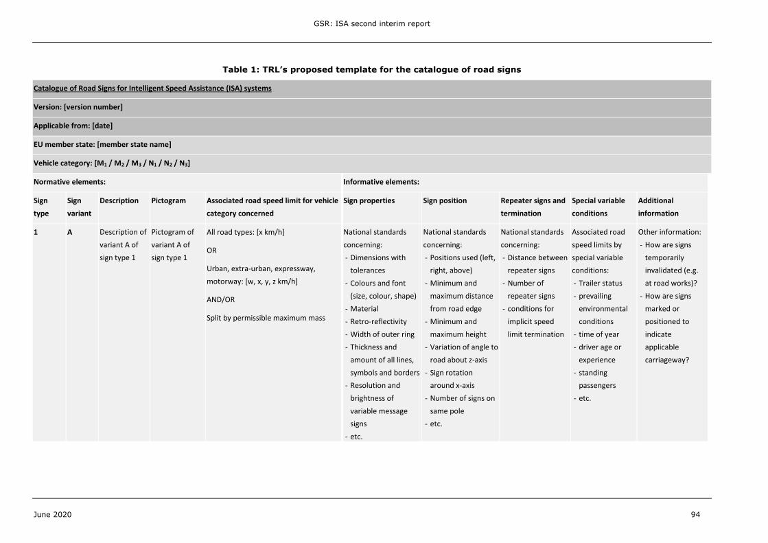
o Catalogue of road signs
There are a large number of signs related to speed limits in the
European Union which are often different between member states
In many cases the speed limit associated with these signs is
different for different vehicle categories In order to prevent
ambiguity the regulation should define precisely the signs based
upon which an approved ISA system should determine road speed
limits (as a minimum) and the speed limits associated with those
signs by vehicle class if appropriate To achieve this it was
proposed that a catalogue of road signs should be made containing
this information
o Cascaded warnings
To some extent defining requirements for an effective warning
indication for ISA involves obtaining a balance between making the
warning intrusive enough so that it is noticeable and easily
recognised by the driver but not so intrusive that it annoys the
driver so that they deactivate the system thus losing any potential
benefit from it To help resolve this problem the idea of allowing the
fitment of a cascaded acoustic warning (on top of a visual warning)
with a time delay and related to the magnitude of the speeding
was proposed
o Region- or country code setting
Knowledge of the current region or country of operation is required
to determine implicit speed limits ie those where a sign does not
show a numerical value (eg a national speed limit sign or a
motorway sign) In order to provide flexibility in the regulation to
design systems which do not have a positioning capability (eg
GPS) the idea was proposed to permit a manual or semi-automatic
setting of the region- or country code
bull Problems which arose
o Mismatch of aspirations
The main problem that arose was an apparent mis-match of the
aspirations between the European Parliament and European
Commission and the industry regarding the minimum capability of
ISA systems that the regulation should mandate the Parliament
GSR ISA second interim report
June 2020 11
and Commission arguably having somewhat higher aspirations than
industry stakeholders
The industry proposed that minimum capability mandated should be
an ISA system which would recognise numerical (explicit) signs only
but with high reliability An advantage of this proposal is that it
should be possible to implement this type of system at a lower cost
using camera technology that is currently readily available A
disadvantage is that coverage of the system may not be as high as
for more advanced systems for example it may not recognise
urban speed limits in some member states which use implicit signs
The Parliament and Commission proposed that the minimum
capability mandated should be higher and include
bull At least recognition of key non-numerical signs
bull A real-world based assessment of the performance of the
ISA system carried out by a technical service
It was noted that an ISA system based on current readily available
technology may require map data to achieve this level of capability
which entails additional cost compared to a camera-only based
system However this cost could be minimised by using a reduced
map stack which only contains the required speed limit
information and not installing an on-board navigation system which
is often included in current vehicles fitted with camera-map fusion
systems Nevertheless it is acknowledged that newly integrating a
positioning system and electronic map elements (in addition to a
camera) into a vehiclersquos EE architecture could be very challenging
within the regulatory timeframe for certain vehicle models Lastly it
should be stated that higher prevalence of explicit speed limit signs
in European member states would make the task to determine the
applicable speed limit considerably easier
o Trucks speed limits
These are often quite different to those posted vary with class of
vehicle and can also vary with other aspects eg the weight of the
load that the truck is carrying
Clearly it is unrealistic to expect the minimum requirements for a
regulated ISA system to take into account the weight of the load
that the truck is carrying to determine the speed limit Therefore it
was proposed that ISA systems on trucks should only be required to
take into account the relevant speed limits in the catalogue which
is not intended to include load related ones and other special
variable conditions (that is conditions which require information
going beyond the current region or country of operation and the
current road class such as trailer status prevailing environmental
conditions time of year driver age or experience or standing
passengers) are excluded from the requirements unless the
relevant electronic signals are available on the vehicle However
further work will be required to determine precisely what speed
limits the catalogue should contain for trucks
In response to the ideas and problems above the approach taken to develop and draft
the requirements and procedures was as follows
bull Define requirements and test procedures in a technology neutral way ie in a
way that aims to allow all technologies included in the regulatory remit (set by
Regulation (EU) 20192144) to be approved if they meet the minimum functional
requirements and performance levels
GSR ISA second interim report
June 2020 12
bull Work to the aspiration level of the European Parliament and European
Commission
bull Take a modular approach to allow implementation in a step-wise fashion if
desired
bull Take industry stakeholder feedback into account for example by removing
design restrictions allowing different test procedures as far as possible and
permitting cascaded warnings and manual or semi-automatic region- or country-
code setting
GSR ISA second interim report
June 2020 13
3 DEVELOPMENT OF REQUIREMENTS AND TEST PROCEDURES
31 Subject matter exemptions and definitions
311 Subject matter
The scope of mandatory ISA fitment is defined in Article 6 of Regulation (EU) 20192144
which refers to ldquoall motor vehicle categoriesrdquo Item D8 of Annex II specifies ISA as
mandatory equipment for vehicle categories M1 M2 M3 N1 N2 and N3 from 5th July 2022
(new types) and 5th July 2024 (new registrations) Approval of separate technical units
(STUs) shall be possible component approval is not envisaged The subject matter of the
draft EC regulation is defined by reference to Regulation (EU) 20192144
Draft text
01 Subject matter
This Regulation establishes detailed technical requirements and test procedures
for the EC type approval of the vehicles referred to in Article 6 of Regulation
(EU) 20192144 in respect of their Intelligent Speed Assistance system and of
Intelligent Speed Assistance separate technical units (lsquoSTUsrsquo)
312 Exemptions
TRL did not in this study identify a need to exempt entire classes of vehicles based on
technical reasons that would make fitment of ISA unfeasible However certain vehicles
could be exempted from certain requirements based on characteristics of their usage
(eg the necessity to exceed the road speed limit during their operation) Note that
requirements for small series or individual approvals are not in scope of this study
ACEA feedback on the first interim report suggested exemptions for ambulances and
police vehicles TRL agrees with this suggestion Usage of such vehicles by private
owners after they are sold on by public authorities at their end of service will be
regulated by national construction and use requirements which may or may not permit
operation without ISA Exemptions from the requirement to fit ISA as drafted by TRL
below based on the wording used in UN Regulation No 17 (prohibition to install side-
facing seats) could be included It could also be considered to exempt relevant vehicles
only from speed limit warning and speed control requirements while still requiring speed
limit information to be displayed to the driver The European Commission will decide
whether and which exemptions are adequate
The industry suggestions to exempt
bull special purpose vehicles (MxS and NxS) was not applied because TRL identified no
convincing justifications for entire classes of special purpose vehicles
bull off-road vehicles (MxG and NxG) was not applied because these vehicles will
frequently be used on-road and should therefore be subject to the same
requirement as other on-road vehicles
bull all top-speed limited vehicles (UN Regulation No 89 on speed limitation devices)
was not applied because these vehicles will still be used on roads with speed limits
lower than their top speed (eg in urban areas at roadworks etc)
bull vehicles that have a limited area of operation such as city buses was not applied
because although the normal operation of these vehicles may be restricted to a
specific geographical area in day-to-day use at least for a certain time following
initial registration based on EC type approval these vehicles will be allowed to be
GSR ISA second interim report
June 2020 14
sold and operated in the entire EU and should therefore be compatible with the
infrastructure in all European countries
Draft text
02 [Exemptions
Ambulances or vehicles intended for use by the armed services civil defence
fire services and forces responsible for maintaining public order are exempted
from the requirement to be equipped with an intelligent speed assistance
system]
313 Definitions
Definitions were drafted as required to ensure that the meaning of the draft text was
clear and unambiguous Note that the definition of lsquoIntelligent Speed Assistancersquo (ISA) is
included by reference to Article 3 of Regulation (EU) 20192144
ldquolsquointelligent speed assistancersquo means a system to aid the driver in maintaining the
appropriate speed for the road environment by providing dedicated and
appropriate feedbackrdquo
Draft text
03 Definitions
For the purposes of this Regulation and in addition to the definitions laid down in
Article 3 of Regulation (EU) 2018858 the following definitions apply
031 ldquoSpeed limit information function (SLIF)rdquo comprises the speed limit
determination system that determines the perceived speed limit and an
interface that communicates the perceived speed limit to the driver
032 ldquoSpeed limit warning function (SLWF)rdquo means a function that alerts the driver
that the speedometer speed is exceeding the perceived speed limit
033 ldquoSpeed control function (SCF)rdquo means a function that attempts to limit the
speedometer speed to a stable speed at or below the perceived speed limit
034 ldquoSpeed limit determination systemrdquo means the specific hardware required to
obtain the speed limit through the observation of road signs and signals based
on infrastructure signals or electronic map data or both
035 ldquoSpeed limit feedback systemrdquo means the specific hardware required to
communicate the speed limit to the driver (SLIF HMI interface) and to provide
feedback to the driver (SLWF or SCF)
036 ldquoSpeedometer speedrdquo means the driving speed of the vehicle as displayed by the
speedometer
037 ldquoRoad speed limitrdquo means the currently applicable maximum permitted legal
driving speed at the vehiclersquos location for the category of vehicle that the ISA
system is fitted to
038 ldquoExplicit speed limit signrdquo means an applicable road sign which shows a
numerical value
039 ldquoImplicit speed limit signrdquo means an applicable road sign which does not show a
numerical value
0310 ldquoPerceived speed limitrdquo means the road speed limit as obtained by the speed
GSR ISA second interim report
June 2020 15
limit determination system
0311 ldquoCatalogue of road signsrdquo means the definitive list of national and regional
variants of road sign types [and variable message sign types] based upon which
ISA shall obtain the perceived speed limit
0312 ldquoApplicable road signrdquo means a sign contained in the catalogue of road signs for
the category of vehicle to be approved and which is applicable to at least one
lane of the vehiclersquos carriageway including both non-electronic signs and
variable message signs but not including speed limit road markings
0313 ldquoCommon spacerdquo means an area on which two or more information functions
(for example symbol) may be displayed but not simultaneously
0314 ldquoSelf-checkrdquo means an integrated function that checks for a system failure on a
continuous basis at least while the system is active
0315 ldquoVehicle master control switchrdquo means the device by which the vehiclersquos on-
board electronics system is brought from being switched off as in the case
where a vehicle is parked without the driver being present to normal operation
mode
0316 ldquoType of ISA STUrdquo means a combination of specific hardware which does not
differ in such essential respects as the characteristics and functionality of the
speed limit determination system and its performance when operated on a public
road located within the territory of the European Union
0317 ldquoVehicle type with regard to the installation of an ISA systemrdquo means motor
vehicles which do not differ in such essential respects as
(a) The characteristics and functionality of the speed limit determination
system
(b) Characteristics of the installation of the speed limit determination
system within the vehicle which significantly influence its performance
when operated on a public road located within the territory of the
European Union
(c) The characteristics and functionality of the speed limit feedback
system
32 General requirements
321 Vehicle and STU approval and multi-stage vehicles
The general requirements on vehicle and STU approval set out the structure of the
subsequent specific requirements which are split into SLIF SLWF and SCF An ISA
system is required to contain a SLIF and at the choice of the manufacturer either a
SLWF or a SCF
For approval of a vehicle with regard to an ISA system all specific requirements apply
as referenced in point 111
For approval of an ISA STU point 113 applies which references the specific
requirements relating to the speed limit determination This is intended to remove the
burden of repeated testing of the speed limit determination system eg camera or
camera-and-map fusion system for a manufacturer or tier 1 supplier if identical systems
are used for different vehicle types If an approved ISA STU is used for speed limit
determination the vehicle approval shall cover the vehicle-related specific requirements
as referenced in point 112 (ie all requirements except 242)
GSR ISA second interim report
June 2020 16
Multi-stage type approvals shall be permissible as long as the ISA system and the
relevant sensors are not modified at subsequent stages
Draft text
11 An ISA system shall comprise a SLIF and either a SLWF or a SCF
111 Type approval of a vehicle with regard to the installation of an ISA system
shall be subject to the vehicle and its system complying with
(a) System requirements laid down in points 21 22 and 23 and
(b) SLIF requirements laid down in point 24 and
(c) SLWF requirements laid down in point 25 or SCF requirements
laid down in point 26
112 Where the motor vehicle is fitted with a type of ISA STU that has been type
approved the vehicle and its system shall have to comply with
(a) System requirements laid down in points 21 22 and 23 and
(b) SLIF requirements laid down in point 241 and
(c) SLWF requirements laid down in point 25 or SCF requirements
laid down in point 26
113 Type approval of an ISA STU shall be subject to the STU complying with
the SLIF requirements laid down in point 242
114 In case of multi-stage type approval the type approval granted at a
previous stage in respect of the installation of an ISA system in the (base)
vehicle shall remain valid provided that the ISA system and the relevant
sensors are not modified
322 Real-driving error rate
Article 6 clause 1 (e) of Regulation (EU) 20192144 demands setting of performance
targets for speed limit determination in real-driving operation
ldquoits performance targets shall be set in order to avoid or minimise the error rate
under real driving conditionsrdquo
This stipulation forms the basis for TRLrsquos proposed real-world driving reliability
requirements and tests (see Sections 3322 and 3413) The general requirement as
drafted below applies the broad regulatory stipulation to minimise or eliminate errors in
real driving conditions by referring to the technically feasible and thus more narrow
conditions laid down in the specific requirements of the draft text (point 2424)
Draft text
12 Subject to specific requirements below the ISA system shall be designed to
avoid or minimise the error rate under real driving conditions
323 Applicability of requirements in the European Economic Area (EEA)
The requirements for ISA in particular relating to determining speed limits associated
with applicable road signs shall only apply on public roads ie excluding private roads
eg car parks where national standards for installation of road signs may not apply and
where speed limits cannot be expected to be mapped reliably
GSR ISA second interim report
June 2020 17
Some non-European Union (EU) member state countries eg Turkey use similar or
identical road signs but may position them differently have different rules regarding
applicability and termination of speed limits and would not be covered in EU map data
ACEA suggested to state clearly that ISA requirements only apply on roads located within
the EU to avoid ambiguity over whether these signs need to be detected by the approved
system TRL agrees with the suggestion of explicit location-based limitations
The European Commission requested application of the requirements to the European
Economic Area (EEA) consisting of the EU member states and Iceland Liechtenstein and
Norway which are part of the EC type approval regime Other countries eg the United
Kingdom or Switzerland shall be free to apply the requirements in national regulation at
their choosing Note that other references in the draft regulation to the lsquoterritory of the
European Unionrsquo may need to change to lsquoterritory of the European Economic Arearsquo which
was left to European Commission legal experts to investigate
The validity of existing approvals shall not be impacted if the composition of the EEA
subsequently changes eg extension with new member states
Draft text
13 The requirements set out in this Regulation shall at least apply when the
vehicle is operated on a public road located within the territory of the
European Economic Area as defined at the time the type approval is
issued
324 Privacy and data protection
The expectations of the European Parliament and the Council of the European Union with
regard to privacy and data protection relating to ISA and other safety systems are set
out in Recitals (10) and (14) of Regulation (EU) 20192144
Recital (10) ldquo[hellip] intelligent speed assistance [hellip] are safety systems that have a
high potential to reduce casualty numbers considerably [hellip] Any such safety
systems should function without the use of any kind of biometric information of
drivers or passengers including facial recognitionrdquo
Recital (14) ldquoAny processing of personal data such as information about the
driver processed in event data recorders or information about the driverrsquos
drowsiness and attention or the driverrsquos distraction should be carried out in
accordance with Union data protection law in particular Regulation (EU) 2016679
of the European Parliament and of the Councilrdquo
From a technology perspective future ISA systems could be envisaged which identify
individual occupants using biometric information to offer personalised settings collate
speed limit compliance records for sharing with insurance providers etc The draft
regulation shall ensure that the ISA functionality required for type-approval is offered
without the need for drivers to provide consent to using biometric information
Should other EU-specific type approval regulations stipulate recording of information
about speed limit compliance eg future event-data recorder (EDR) or data storage
systems for automated driving (DSSA) requirements this information may be provided
by the type approved ISA system to avoid the necessity to install an additional system
for that purpose
Processing of personal data shall be carried out in accordance with applicable data
protection legislation However TRL in line with stakeholder feedback received
considers it not necessary to include a specific stipulation in the type approval regulation
as relevant Union data protection law automatically applies
GSR ISA second interim report
June 2020 18
Draft text
14 Privacy and data protection
141 The ISA system shall offer the required functionality in the normal
operation mode without the use of biometric information including facial
recognition of any vehicle occupants
142 The ISA system shall not continuously record nor retain any data related to
incidents of exceeding the speed limit other than what is necessary in
relation to perform the required ISA functionality or other European Union
specific regulatory acts regarding vehicle approval
33 Specific requirements
The specific requirements were divided into the following four main parts
bull ISA failure warning control and provisions for Periodic Technical Inspection (PTI)
the first two of which are related to the Human Machine Interface (HMI)
bull Speed Limit Information Function (SLIF)
bull Speed Limit Warning Function (SLWF)
bull Speed Control Function (SCF)
331 ISA failure warning control and provisions for Periodic Technical Inspection
Failure warning
Following a similar approach to other regulations (eg UN Regulations No 130 and 152)
text was drafted to require a constant optical failure warning signal for electrically
detectable failures and non-electrical failures such as sensor obscuration excluding
temporary obscuration such as sun glare This warning signal can also be used to
indicate when the system is deactivated In other regulations this signal is often
mandated to be yellow However this requirement was dropped because systems which
use other colours may already be in use ie fitted to vehicles
Draft text
21 ISA failure warning
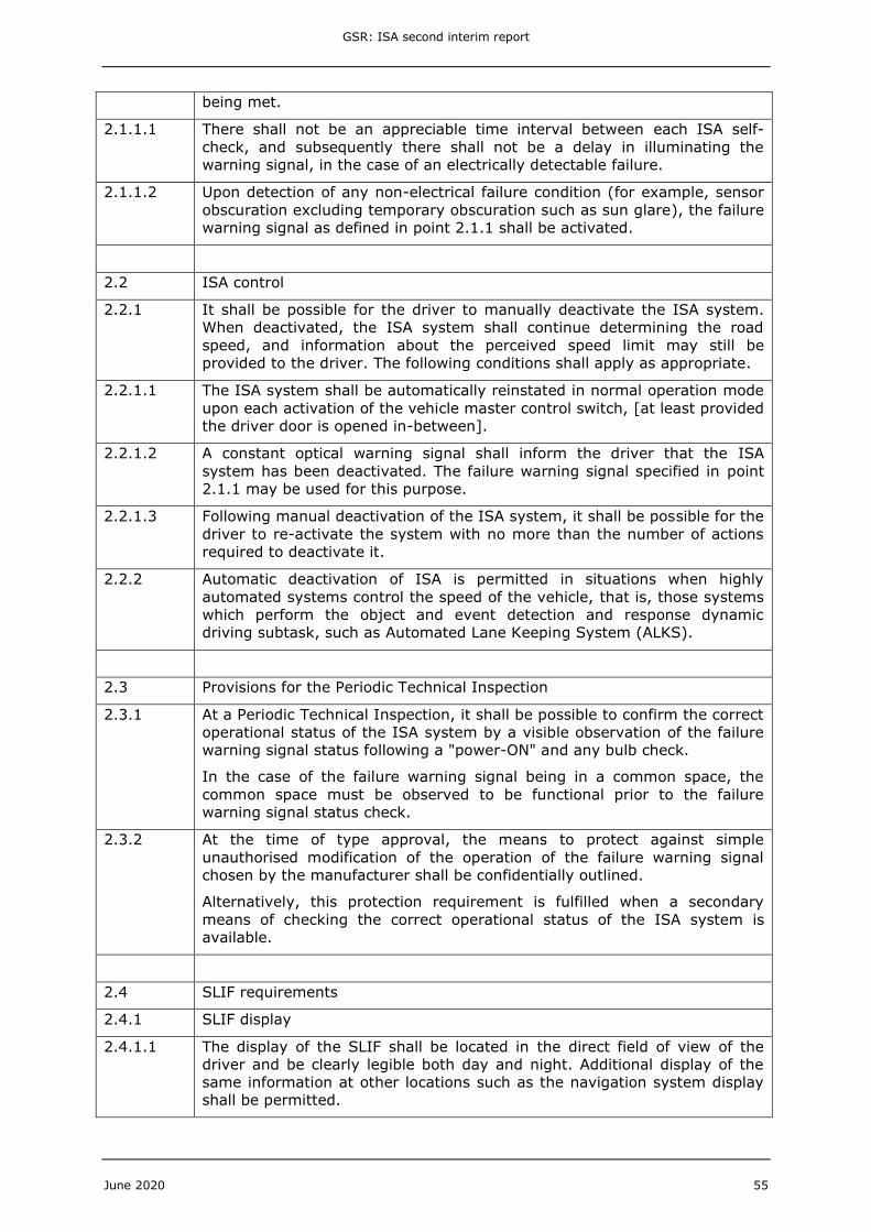
211 A constant optical warning signal shall be provided when there is a failure
in the ISA system that prevents the requirements of this Regulation of
being met
2111 There shall not be an appreciable time interval between each ISA self-
check and subsequently there shall not be a delay in illuminating the
warning signal in the case of an electrically detectable failure
2112 Upon detection of any non-electrical failure condition (for example sensor
obscuration excluding temporary obscuration such as sun glare) the failure
warning signal as defined in point 211 shall be activated
Control (Deactivation re-activation)
Regulation (EU) 20192144 Article 6 clause 2 (b) requires
ldquoit shall be possible to switch off the [ISA] system information about the speed
limit may still be provided and intelligent speed assistance shall be in normal
operation mode upon each activation of the vehicle master control switchrdquo
GSR ISA second interim report
June 2020 19
Text was drafted to reflect these requirements ie require fitment of a means to
deactivate the ISA and its reinstatement upon each activation of the vehicle master
control switch However for the Emergency Lane Keep System (ELKS) draft text a
stakeholder requested that the text related to the reinstatement be modified by adding
the part in square brackets see below
ldquoThe ISA system shall be automatically reinstated in normal operation mode upon
each activation of the vehicle master control switch [at least provided the driver
door is opened in-between]rdquo
This additional text is also included here to be consistent with the ELKS draft text The
reason given for it was to cover situations when the driver has not completed a journey
and has for example switched their car off at traffic lights or in a traffic jam to save fuel
or indeed has stalled the car Reinstatement of the ISA in these situations could increase
customer annoyance As for the ELKS text the Commission should consider whether or
not this proposed modification should be included in the draft text
Regulation (EU) 20192144 Recital (11) states in regard to the switch-off feature
ldquo[hellip] It should allow for intelligent speed assistance to be switched off for as long
as necessary and to be easily switched back on by the driver [hellip] and the driver
should always be made aware of whether the system is on or offrdquo
To help ensure that a driver is not discouraged from re-activating the ISA system after
deactivating it and in line with Recital (11) draft text was added to require that it should
not be more onerous to reactivate the system than deactivating it (point 2213) and
that the driver shall be informed when the system is deactivated (point 2212) Note
that TRLrsquos initial suggestion in the first interim report (Seidl et al 2020) to require a
specific ISA OFF tell-tale using a harmonised symbol has not been included in the draft
text based on industry feedback If a harmonised symbol is considered appropriate in the
future this should be included in UN Regulation No 121
In addition in alignment with stakeholder feedback draft text was written to permit
automatic deactivation of the ISA when lsquohighly automated systemsrsquo and not the driver
control the speed of the vehicle It should be noted that lsquohighly automated systemsrsquo are
SAE level 3 and above systems as defined in SAE J3016_2018061 and do not include SAE
level 2 systems such as Adaptive Cruise Control with lane centering Care was taken to
ensure that this was clear in the draft text by including reference to a definition of these
systems ie lsquothose systems which perform the object and event detection and response
dynamic driving subtaskrsquo and to give an example of such a system ie Automated Lane-
Keeping System (ALKS) for low speed application
ALKS for low speed application is a system which is activated by the driver and which
keeps the vehicle within its lane for travelling speed of 60 kmh or less by controlling the
lateral and longitudinal movements of the vehicle for extended periods without the need
for further driver input which operates continuously under ldquohands offrdquo driver supervision
Draft text
22 ISA control
221 It shall be possible for the driver to manually deactivate the ISA system
When deactivated the ISA system shall continue determining the road
speed and information about the perceived speed limit may still be
provided to the driver The following conditions shall apply as appropriate
1 SAE J3016_201806 Available from httpssaemobilussaeorgcontentj3016_201806
GSR ISA second interim report
June 2020 20
2211 The ISA system shall be automatically reinstated in normal operation mode
upon each activation of the vehicle master control switch [at least provided
the driver door is opened in-between]
2212 A constant optical warning signal shall inform the driver that the ISA
system has been deactivated The failure warning signal specified in point
211 may be used for this purpose
2213 Following manual deactivation of the ISA system it shall be possible for the
driver to re-activate the system with no more than the number of actions
required to deactivate it
222 Automatic deactivation of ISA is permitted in situations when highly
automated systems control the speed of the vehicle that is those systems
which perform the object and event detection and response dynamic
driving subtask such as Automated Lane Keeping System (ALKS)
Periodic Technical Inspection (PTI)
Provisions for PTI were drafted based closely on those in UN Regulation No 152 for
Advanced Emergency Braking Systems (AEBS) for M1 and N1 vehicles
Draft text
23 Provisions for the Periodic Technical Inspection
231 At a Periodic Technical Inspection it shall be possible to confirm the correct
operational status of the ISA system by a visible observation of the failure
warning signal status following a power-ON and any bulb check
In the case of the failure warning signal being in a common space the
common space must be observed to be functional prior to the failure
warning signal status check
232 At the time of type approval the means to protect against simple
unauthorised modification of the operation of the failure warning signal
chosen by the manufacturer shall be confidentially outlined
Alternatively this protection requirement is fulfilled when a secondary
means of checking the correct operational status of the ISA system is
available
332 Speed Limit Information Function (SLIF) requirements
3321 SLIF display
The draft text for the SLIF display was written taking the following high-level intent and
justification into account
bull Display speed limit at least when it is exceeded
o Regulation (EU) 20192144 Article 6 clause 2 (a) requires that ldquoit shall be
possible for the driver to be made aware through the accelerator control or
through dedicated appropriate and effective feedback that the applicable
speed limit is exceededrdquo
The regulation does not contain a requirement for a permanent
speed limit information function (SLIF) but only requires feedback
when the speed limit is exceeded TRL interpret the requirement of
lsquoeffectiversquo and lsquoappropriatersquo feedback to include providing the driver
GSR ISA second interim report
June 2020 21
with information about the current limit at least when exceeding it
Otherwise the driver would not be able to determine by how much
the driving speed needs to be reduced or why it is being controlled
by the vehicle
Stakeholder feedback supported a requirement for a non-
permanent SLIF A reason given for this was to allow other
information to be displayed in place of the SLIF when the speed
limit is not being exceeded for example for truck drivers a
recommended driving speed for economy or other reasons which
could be lower than the road speed limit
bull Display located in the direct field of view of the driver
o Guidance was taken from
UN Regulation No 39 on speedometers which requires that the
display rdquoshall be located within the direct field of view of the driver
and shall be clearly legible both day and nightrdquo
Euro NCAP Speed Assist System Assessment Protocol (Euro NCAP
2019) requires that the display ldquoshall be clearly seen in the direct
field of view of the driver without the need for the head to be
moved from the normal driving positionrdquo
bull Detailed display options
o Euro NCAP have a requirement that rdquothe speed limit shall be shown using a
traffic signrdquo This requirement has influenced many current systems fitted
to cars and vans
o UN Regulation No 89 requires that adjustable speed limitation functions
(ASLF) permanently indicate the adjustable speed limit value to the driver
Some systems achieve this via display on the speedometer
o Ideally regulation should encourage competition as much as possible by
enforcing the minimum required and not restricting design solutions
Stakeholder feedback supported this principle
o On this basis two options were drafted the first a display on the
speedometer and the second a separate display using a numerical value or
a symbol resembling a Vienna Convention speed limit traffic sign
bull Display permitted when ISA system switched off
o Regulation (EU) 20192144 Article 6 clause 2 (b) stipulates
that rdquoinformation about the speed limit may still be providedrdquo when the
ISA system is switched off
Draft text
241 SLIF display
2411 The display of the SLIF shall be located in the direct field of view of the
driver and be clearly legible both day and night Additional display of the
same information at other locations such as the navigation system display
shall be permitted
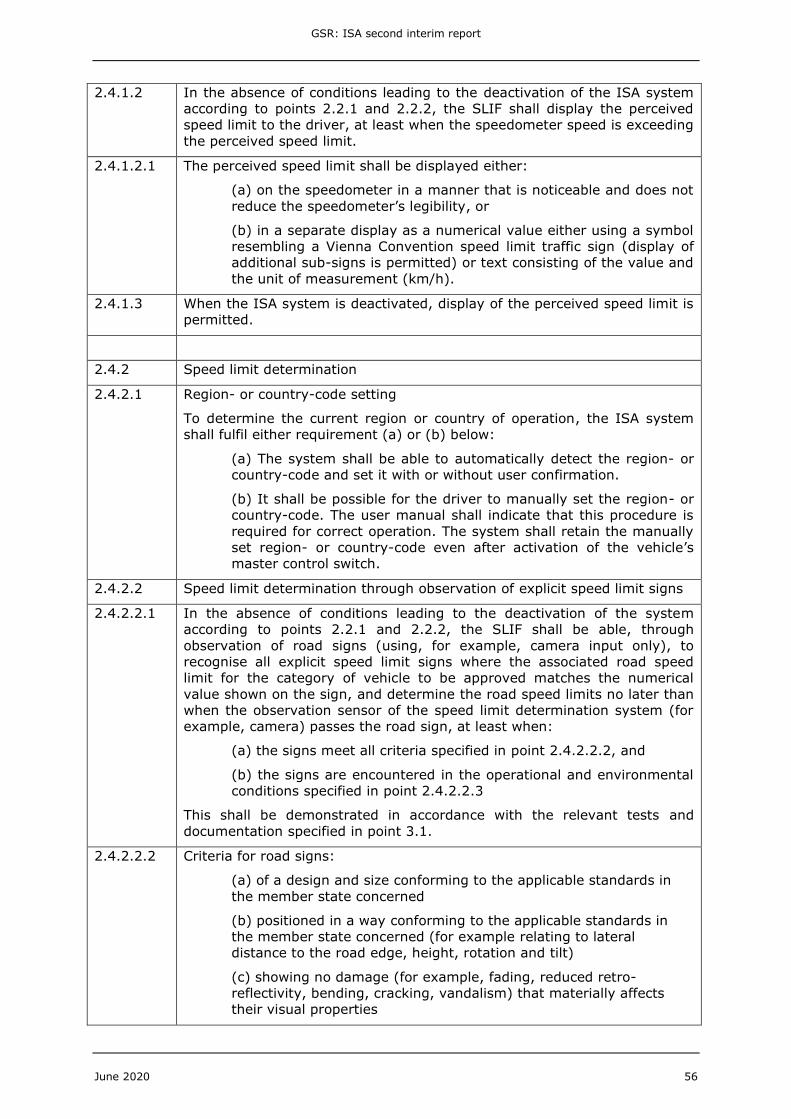
2412 In the absence of conditions leading to the deactivation of the ISA system
according to points 221 and 222 the SLIF shall display the perceived
speed limit to the driver at least when the speedometer speed is exceeding
the perceived speed limit
GSR ISA second interim report
June 2020 22
24121 The perceived speed limit shall be displayed either
(a) on the speedometer in a manner that is noticeable and does not
reduce the speedometerrsquos legibility or
(b) in a separate display as a numerical value either using a symbol
resembling a Vienna Convention speed limit traffic sign (display of
additional sub-signs is permitted) or text consisting of the value and
the unit of measurement (kmh)
2413 When the ISA system is deactivated display of the perceived speed limit is
permitted
3322 Speed limit determination
Regulatory remit
Article 6 clause 1 (c) of Regulation (EU) 20192144 specifies the sources from which the
ISA system shall be capable to derive speed limit information
ldquothe dedicated and appropriate feedback shall be based on speed limit
information obtained through the observation of road signs and signals based on
infrastructure signals or electronic map data or both made available in-vehiclerdquo
Based on this observation of (conventional ie non-electronic) roads signs is a
minimum functional requirement which at the current state of technology is usually
realised by an in-vehicle camera Observation of signals which is also a necessary
requirement can be interpreted to relate to items such as variable message signs
vehicle-to-infrastructure signals or electronic map data Based on the current state of
technology the regulatory stipulation therefore includes in principle camera-only
systems (with the ability to interpret variable message signs) and camera-map fusion
systems but does not include map-only systems because these donrsquot observe road signs
The draft requirements for speed limit determination have therefore been written in a
technology neutral way ie in a way that aims to allow all technologies included in the
regulatory remit above to be approved if they meet the minimum functional requirements
and performance levels One of the important aspects in this regard is to only require
determination of speed limits which are indicated by an applicable road sign (which
means a sign contained in the catalogue of road signs for the category of vehicle to be
approved and which is applicable to at least one lane of the vehiclersquos carriageway
including both non-electronic signs and variable message signs but not including speed
limit road markings) other signs may be used by an advanced system but are not
required Note that the catalogue of road signs is yet to be defined and populated by the
European Commission (see Section 41)
Functional requirements
In order to operate effectively an ISA system must be capable of determining the speed
limit that is currently in force for the specific vehicle and road upon which it is travelling
There are a number of important elements to this task
bull The system must be capable of recognising and correctly interpreting a range of
permanent and temporary non-electronic road signs and electronic variable
message signs
bull The system must know the country (and in some cases region) in which the
vehicle is travelling
bull The system must know the class of road on which it is travelling
GSR ISA second interim report
June 2020 23
For sign recognition and interpretation the task splits into two relevant categories
bull Explicit speed limit signs meaning signs (non-electronic and electronic) which
show a numerical value For passenger cars and vans these signs can mostly be
directly interpreted as the applicable speed limit For heavy vehicles the situation
is more complex in that certain signs are not applicable to these vehicles because
a lower implicit speed limit may apply based for example on the current
countryregion or road class The requirements in point 2422 specify that the
ISA system shall be able to recognise (eg using camera input) and interpret
those explicit signs where the associated road speed limit for the category of
vehicle to be approved matches the numerical value shown on the sign
bull Implicit speed limit signs meaning signs (non-electronic and electronic) which do
not show a numerical value such as city entry signs or national speed limit signs
For correct interpretation of the speed limit these signs require knowledge of the
current countryregion andor road class The requirements in point 2423
specify that the ISA system shall be able to determine (using all relevant system
inputs eg using camera input and map data where applicable) speed limits
associated with implicit signs (and with explicit signs which are included in the
catalogue of road signs but where the associated speed limit does not match the
numerical value shown on the sign)
Irrespective of the type of system (camera-only or camera-map fusion) the
requirements only include speed limits which are indicated by road signs contained in the
catalogue of road signs (see definition lsquoapplicable road signrsquo) and meet the criteria for
sign design size positioning condition and obscuration defined in point 24222 and
are encountered in the conditions defined in point 24223 The rationale underlying this
decision is that technology neutral requirements should in principle allow systems to
determine the speed limit with information that is available to be obtained in principle
from visual observation of the road scene by a human driver ISA is not an automated
driving feature but a driver assistance system which remains under the control of the
driver and can only slow a vehicle down but not accelerate it to unsafe speeds
Therefore the system should not be required to compensate for shortcomings in
infrastructure design or maintenance which would also make speed limit determination
challenging for human drivers
The country (and in some cases region) in which the vehicle is travelling can be derived
automatically from on-board positioning systems (eg GNSS such as GPS) and map data
or from camera observation of the road signs encountered the latter was described by
stakeholders as less reliable at the current state of technology In order to provide
maximum flexibility point 2421 of the draft text permits either automatic detection
(with the option to request confirmation of country changes by the driver for less reliable
solutions) or manual setting by the driver Manual setting would be the least convenient
option for drivers however might represent the solution that is easiest to implement It
should be noted that automatic countryregion detection by GNSS would not require a
full map-stack as used for a full navigation solution but could be realised in a more cost-
effective way by using a reduced map stack only providing a countryregion border layer
The class of road on which the vehicle is travelling can be derived from on-board
positioning and map data or from camera observation of signs (eg motorway
expressway) and interpretation of road characteristics using machine vision (eg number
of lanes divided by central barrier) for the latter approach advanced camera systems
are required and it was described by stakeholders as less reliable at the current state of
technology Again for vehicles without an on-board navigation system a reduced map
stack could be used which only provides the road class layer for Europe
TRL suggests that other variable conditions which influence the applicable implicit speed
limit and change frequently are not required to be taken into account for speed limit
determination unless the relevant electronic signals are available (point 24232)
Examples include trailer status prevailing environmental conditions time of year driver
age or experience and standing passengers in buses and coaches In these cases TRL
GSR ISA second interim report
June 2020 24
proposes that manufacturers base the perceived speed limit to which the system defaults
to on the assumed most common condition in normal operation The manufacturer is
free to fit additional sensors to sense the current conditions and determine the correct
road speed limit In effect this provision accepts that in certain variable conditions that
cannot be detected by existing in-vehicle sensors an incorrect speed limit will be
determined that is too high or too low The Commission should consider whether or not
this provision should be included in the draft text
Considering the challenges outlined above in deriving speed limits from implicit signs and
for heavy vehicles in general stakeholder feedback from industry suggested to focus
requirements only on explicit signs (and require a high reliability for those) in order to
ensure robust speed limit determination on road sections covered by explicit signs and
accept the reduced coverage from excluding all implicit speed limits In this study TRL
could not identify the proportions of the European road network which are covered by
explicit and implicit signs However considering that in many countries implicit signs are
often the only sign to indicate urban speed limits and the national speed limit on rural
roads (ie the system would not work in these cases) both of which have a high casualty
burden relating to vulnerable road users and vehicle occupants respectively TRL
consider it necessary to include speed limits associated with implicit signs to provide
adequate casualty benefits Nevertheless TRL support the industry suggestion to exclude
from the set of required signs (at least initially) specific national variants which have
characteristics that make them difficult to recognise (eg French city entry signs have
different dimensions based on the length of the city name) Lastly it should be stated
that higher prevalence of explicit speed limit signs in European member states would
make the task to determine the applicable speed limit considerably easier
Real-world reliability requirements
Regulation (EU) 20192144 specifies that real-driving performance targets shall be set
for ISA systems (see Section 322) Poor reliability of speed limit determination ie
failure to determine a road speed limit or incorrect determination could cause driver
annoyance reduce confidence in and acceptance of the ISA system and increase driversrsquo
inclination to deactivate the system resulting in the loss of associated casualty benefits
TRL specified using information about established practice obtained in industry
consultations three performance metrics to measure real-world reliability in point
24242 of the draft text
bull True positive rate (associated with event-based performance)
bull False positive rate (associated with event-based performance)
bull True positive distance (associated with distance-based performance)
TRL suggest that all three metrics shall be measured because they put emphasis on
different aspects of reliability and present more challenges respectively on lower speed
road segments where signs are repeated more frequently and high-speed segments
where much positive test distance can be accumulated with few sign detections The two
event-based metrics are calculated on the basis of the number of sign passing events
and aim to ensure respectively that a high number of applicable signs is interpreted
correctly and that a low number of non-applicable signs or other roadside objects is used
mistakenly to determine a speed limit The distance-based metric aims to ensure that a
high proportion of the distance driven is covered with correct speed limit information
Distance-based measurements take the retention period of speed limit information (ie
after what distance after a sign passing event does the ISA system determine lsquospeed
limit unknownrsquo) into account implicitly TRL therefore decided based on stakeholder
feedback and to ensure design freedom by manufacturers and tier 1 suppliers to not
prescribe explicit minimum retention periods in the draft text
The passfail thresholds for the above performance metrics also specified in point
24242 were defined by the European Commission and included in the report at their
GSR ISA second interim report
June 2020 25
request In TRLrsquos view taking into account input from individual stakeholders these
values appear suitable to ensure an adequate minimum performance level and technical
feasibility however should be further confirmed in trials Stakeholder have not had an
opportunity to comment on these values before this report was written When
interpreting the thresholds it needs to be understood that the prescribed values take into
account only stretches of road where the speed limit is indicated by a road sign contained
in the catalogue and where the conditions outside the control of the in-vehicle system are
favourable for system performance (ie only road signs which are of the correct size and
design positioned correctly not materially damaged and not obscured and which are
encountered in conditions excluding fog or direct blinding sunlight) This means that
shortcomings in infrastructure design or maintenance and environmental conditions that
can be challenging for sign detection and recognition are not counted negatively towards
system performance
Some industry stakeholders were critical of implementing real-world reliability
requirements taking into account implicit signs and asserted that camera-only technology
available for implementation within the timeframe set by the regulation might not be able
to provide sufficient reliability for customer satisfaction (The stakeholder suggestion to
focus on explicit signs only instead is discussed above) Other industry stakeholders and
the European GNSS Agency GSA argued that the optimal solution were camera-map
fusion systems because camera-only systems would incur additional cost for harmonising
and better maintaining road signs and because there will be situations where one of the
sensors does not work and could be complemented by the other (eg bad weather for
camera tunnels for positioning technology) Implementation of camera-map fusion
systems is considered more costly for vehicle manufacturers however it should be
noted that there would not be a requirement for a full navigation map but only the
speed limit layer which is more cost effective Nevertheless it is acknowledged that
newly integrating a positioning system and electronic map elements (in addition to a
camera) into a vehiclersquos EE architecture could be very challenging within the regulatory
timeframe for certain vehicle models It is important to note that trials of the real-world
procedure were not in scope of this study and TRL therefore consider it important that an
investigation is performed whether the suggested passfail thresholds can be met with
different types of currently available systems before the procedure is implemented in
legislation Possible approaches could include a dedicated trial programme and or
implementation of the real-world reliability tests as a monitoring requirement for an
initial phase before enforcement of passfail thresholds as was done for the Real Driving
Emissions (RDE) test procedure
Stakeholder inputs to this study indicated that the reliability of speed limit determination
of current systems can vary considerably between different countries based on
characteristics of the national infrastructure (road layout sign positioning frequency of
signs prevalence of explicit speed limit signs etc) or availability and accuracy of map
data To ensure adequate performance EU-wide TRL therefore initially consulted on a
suggestion to require extended real-world driving tests to be carried out by the
manufacturer and performance be reported for all EU member states see (Seidl et al
2020) Taking into account stakeholder feedback which emphasised the disproportionate
effort involved in this approach and direction given by the European Commission TRL
developed the more efficient approach to require testing in at least one EU member state
to be performed by the technical service and supplemented by additional documentation
for audit that describes and evidences the due diligence activities performed by the
manufacturer to ensure adequate EU-wide performance (see point 24244) These
manufacturer activities could include for example identification of and testing in the
country that is considered most challenging for the specific system implemented (worst-
case testing) andor a quality assessment of the map data used throughout the EU
Life cycle performance requirements
Regulation (EU) 20192144 Recital (10) states for ISA and other regulated safety
systems that
GSR ISA second interim report
June 2020 26
ldquoIt is [hellip] necessary to ensure that those systems can be used safely throughout
the life cycle of the vehiclerdquo
For speed limit determination ISA is heavily dependent on the infrastructure it operates
in because a variety of factors impacting visual road sign observation can change over
time (including the design condition and positioning of road signs as well as the
definition of their implicit meaning) and speed limits of specific roads change sometimes
TRL have therefore drafted requirements on life cycle performance with the aim to
balance the need for continued reliability of speed limit determination for safe operation
with technical feasibility (point 24245) The requirements shall ensure that the
observation system continues to recognise changes to posted speed limits (eg by giving
priority to detected signs over map information in relevant circumstances) and that
frequent updates to map data are offered to vehicles owners if applicable
Acknowledging the technical difficulties that would be associated with requiring
recognition of new sign designs or types that were developed after type approval (note
that hardware updates might be required in some cases where the processing
capabilities of cameras are not sufficient for additional classifiers) the requirements as
drafted are limited to speed limits that were included in the catalogue of road signs at
the time of approval
An adequate time period after definite discontinuation of production still needs to be
decided The preliminary value of 10 years was defined by the European Commission and
included in the report at their request
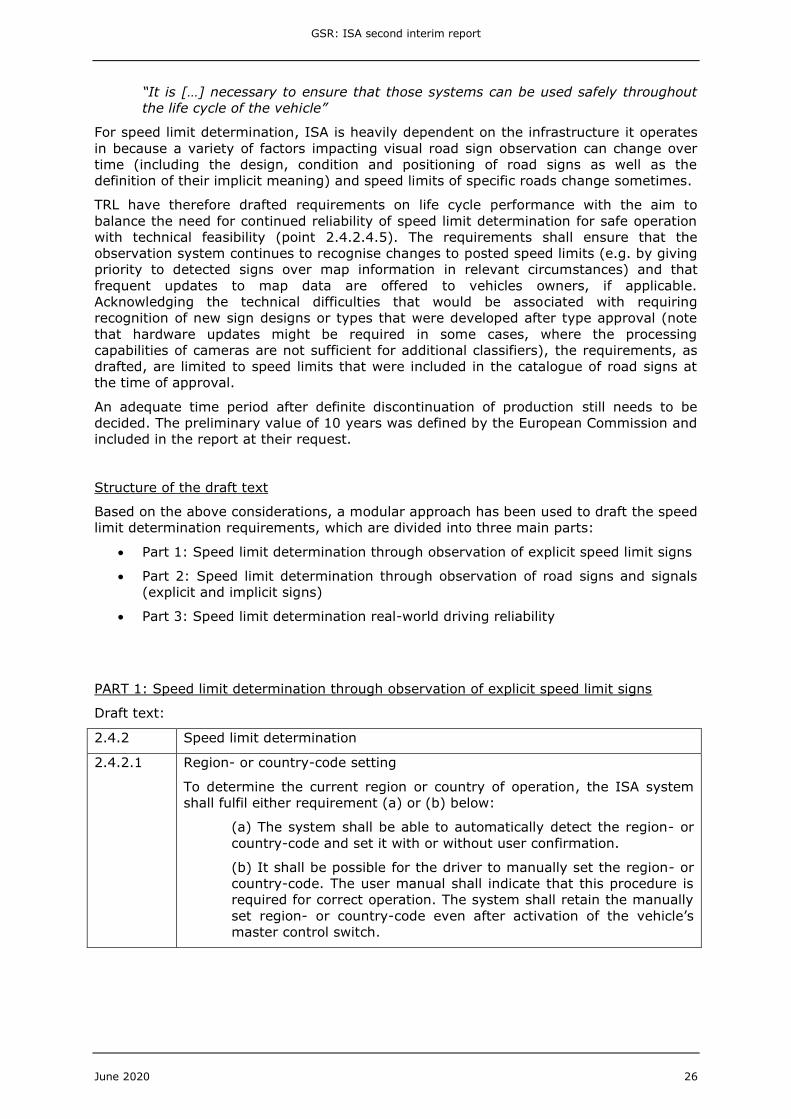
Structure of the draft text
Based on the above considerations a modular approach has been used to draft the speed
limit determination requirements which are divided into three main parts
bull Part 1 Speed limit determination through observation of explicit speed limit signs
bull Part 2 Speed limit determination through observation of road signs and signals
(explicit and implicit signs)
bull Part 3 Speed limit determination real-world driving reliability
PART 1 Speed limit determination through observation of explicit speed limit signs
Draft text
242 Speed limit determination
2421 Region- or country-code setting
To determine the current region or country of operation the ISA system
shall fulfil either requirement (a) or (b) below
(a) The system shall be able to automatically detect the region- or
country-code and set it with or without user confirmation
(b) It shall be possible for the driver to manually set the region- or
country-code The user manual shall indicate that this procedure is
required for correct operation The system shall retain the manually
set region- or country-code even after activation of the vehiclersquos
master control switch
GSR ISA second interim report
June 2020 27
2422 Speed limit determination through observation of explicit speed limit signs
24221 In the absence of conditions leading to the deactivation of the system
according to points 221 and 222 the SLIF shall be able through
observation of road signs (using for example camera input only) to
recognise all explicit speed limit signs where the associated road speed
limit for the category of vehicle to be approved matches the numerical
value shown on the sign and determine the road speed limits no later than
when the observation sensor of the speed limit determination system (for
example camera) passes the road sign at least when
(a) the signs meet all criteria specified in point 24222 and
(b) the signs are encountered in the operational and environmental
conditions specified in point 24223
This shall be demonstrated in accordance with the relevant tests and
documentation specified in point 31
24222 Criteria for road signs
(a) of a design and size conforming to the applicable standards in
the member state concerned
(b) positioned in a way conforming to the applicable standards in
the member state concerned (for example relating to lateral
distance to the road edge height rotation and tilt)
(c) showing no damage (for example fading reduced retro-
reflectivity bending cracking vandalism) that materially affects
their visual properties
(d) not partially or fully covered (for example foliage snow or dirt
obscuring the sign or deliberate invalidation during roadworks)
24223 Operational and environmental conditions
(a) full operating speed range of the vehicle
(b) with unobstructed view of the road sign for a continuous period
of at least 05 seconds
(c) in all illumination conditions without direct blinding sunlight and
dipped (passing) beam head lamps if necessary
(d) in the absence of weather conditions affecting the visibility of
road signs (for example fog)
GSR ISA second interim report
June 2020 28
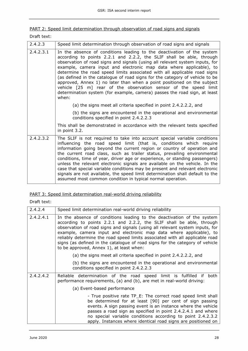
PART 2 Speed limit determination through observation of road signs and signals
Draft text
2423 Speed limit determination through observation of road signs and signals
24231 In the absence of conditions leading to the deactivation of the system
according to points 221 and 222 the SLIF shall be able through
observation of road signs and signals (using all relevant system inputs for
example camera input and electronic map data where applicable) to
determine the road speed limits associated with all applicable road signs
(as defined in the catalogue of road signs for the category of vehicle to be
approved Annex 1) no later than when a point positioned on the subject
vehicle [25 m] rear of the observation sensor of the speed limit
determination system (for example camera) passes the road sign at least
when
(a) the signs meet all criteria specified in point 24222 and
(b) the signs are encountered in the operational and environmental
conditions specified in point 24223
This shall be demonstrated in accordance with the relevant tests specified
in point 32
24232 The SLIF is not required to take into account special variable conditions
influencing the road speed limit (that is conditions which require
information going beyond the current region or country of operation and
the current road class such as trailer status prevailing environmental
conditions time of year driver age or experience or standing passengers)
unless the relevant electronic signals are available on the vehicle In the
case that special variable conditions may be present and relevant electronic
signals are not available the speed limit determination shall default to the
assumed most common condition in typical normal operation
PART 3 Speed limit determination real-world driving reliability
Draft text
2424 Speed limit determination real-world driving reliability
24241 In the absence of conditions leading to the deactivation of the system
according to points 221 and 222 the SLIF shall be able through
observation of road signs and signals (using all relevant system inputs for
example camera input and electronic map data where applicable) to
reliably determine the road speed limits associated with all applicable road
signs (as defined in the catalogue of road signs for the category of vehicle
to be approved Annex 1) at least when
(a) the signs meet all criteria specified in point 24222 and
(b) the signs are encountered in the operational and environmental
conditions specified in point 24223
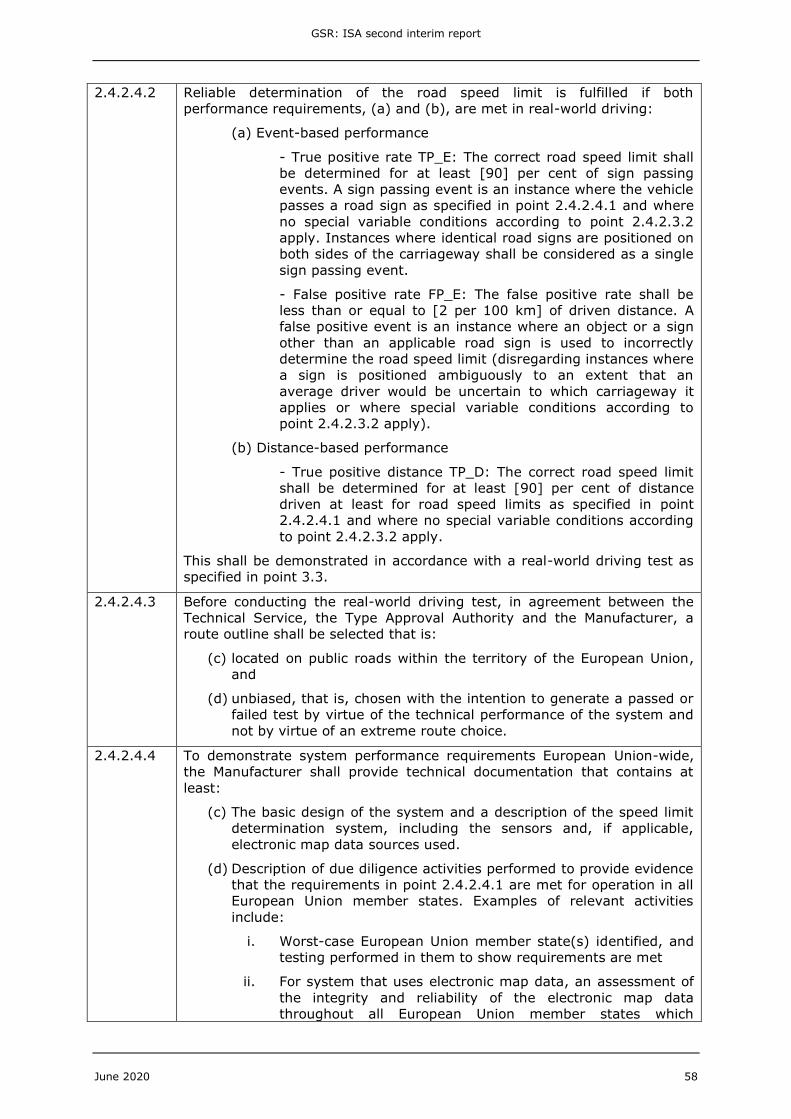
24242 Reliable determination of the road speed limit is fulfilled if both
performance requirements (a) and (b) are met in real-world driving
(a) Event-based performance
- True positive rate TP_E The correct road speed limit shall
be determined for at least [90] per cent of sign passing
events A sign passing event is an instance where the vehicle
passes a road sign as specified in point 24241 and where
no special variable conditions according to point 24232
apply Instances where identical road signs are positioned on
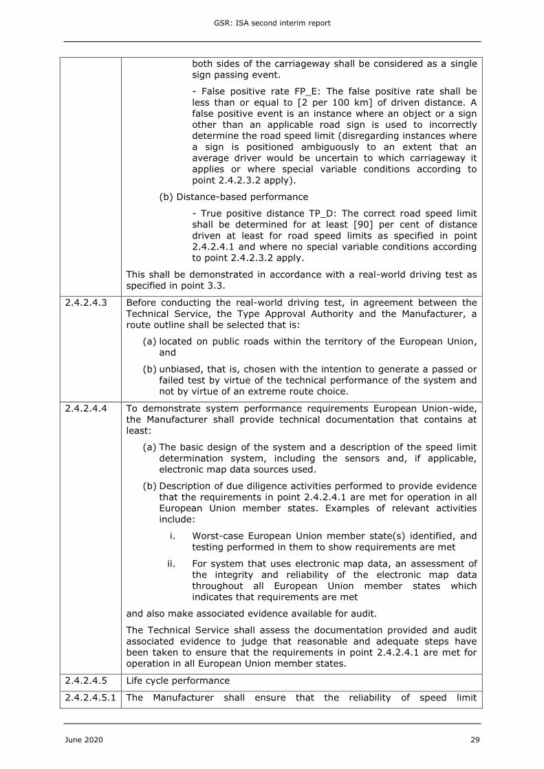
GSR ISA second interim report
June 2020 29
both sides of the carriageway shall be considered as a single
sign passing event
- False positive rate FP_E The false positive rate shall be
less than or equal to [2 per 100 km] of driven distance A
false positive event is an instance where an object or a sign
other than an applicable road sign is used to incorrectly
determine the road speed limit (disregarding instances where
a sign is positioned ambiguously to an extent that an
average driver would be uncertain to which carriageway it
applies or where special variable conditions according to
point 24232 apply)
(b) Distance-based performance
- True positive distance TP_D The correct road speed limit
shall be determined for at least [90] per cent of distance
driven at least for road speed limits as specified in point
24241 and where no special variable conditions according
to point 24232 apply
This shall be demonstrated in accordance with a real-world driving test as
specified in point 33
24243 Before conducting the real-world driving test in agreement between the
Technical Service the Type Approval Authority and the Manufacturer a
route outline shall be selected that is
(a) located on public roads within the territory of the European Union
and
(b) unbiased that is chosen with the intention to generate a passed or
failed test by virtue of the technical performance of the system and
not by virtue of an extreme route choice
24244 To demonstrate system performance requirements European Union-wide
the Manufacturer shall provide technical documentation that contains at
least
(a) The basic design of the system and a description of the speed limit
determination system including the sensors and if applicable
electronic map data sources used
(b) Description of due diligence activities performed to provide evidence
that the requirements in point 24241 are met for operation in all
European Union member states Examples of relevant activities
include
i Worst-case European Union member state(s) identified and
testing performed in them to show requirements are met
ii For system that uses electronic map data an assessment of
the integrity and reliability of the electronic map data
throughout all European Union member states which
indicates that requirements are met
and also make associated evidence available for audit
The Technical Service shall assess the documentation provided and audit
associated evidence to judge that reasonable and adequate steps have
been taken to ensure that the requirements in point 24241 are met for
operation in all European Union member states
24245 Life cycle performance
242451 The Manufacturer shall ensure that the reliability of speed limit
GSR ISA second interim report
June 2020 30
determination is maintained for at least [10 years] after the production of
the approved type is definitely discontinued This only applies to road speed
limits as specified in point 24241 in the version of this Regulation at the
time the type approval was issued
242452 If electronic map data is used to achieve the required performance the
Manufacturer shall offer frequent data updates to vehicle owners These
updates shall be made available to vehicle owners free of charge The user
manual shall indicate that updates are required to maintain performance
and explain the procedure to perform updates
333 Speed Limit Warning Function (SLWF) requirements
The draft text for the SLWF was written taking the following high-level intent and
justifications into account
bull Link of warning to speedometer speed
o It was decided to link the warning to speedometer speed rather than true
vehicle speed The main reason for this was to reduce potential for driver
confusion by ensuring a direct link of the warning to the speed indicated on
the speedometer This approach was supported by stakeholders although
they also supported the idea of an adjustable warning threshold However
an adjustable threshold was not deemed appropriate because mandatory
ISA system should aim to enforce the applicable legal road speed limit It
could be argued that because a speedometer always under-predicts the
true vehicle speed allowing some upward adjustment would still ensure
that the legal speed limit should not be exceeded However this cannot be
guaranteed without knowing precisely how inaccurate the speedometer
reading is (which is not known) and it could send the wrong message to
the driver in terms of adhering to the speed limit
bull Warning indication
o Drafting requirements for an effective warning indication for ISA is
challenging because it involves obtaining a balance between making the
warning intrusive enough so that it is noticeable and easily recognised by
the driver but not so intrusive that it annoys the driver so that they
deactivate the system thus losing any potential benefit from it If the ISA
system produces a large number of false warnings ie gives a warning
when the vehicle is not actually speeding this can annoy a driver even
more and thus is also an important factor
o Current ISA systems are usually designed to Euro NCAP criteria and often
have a visual warning only although some have an acoustic warning
mostly implemented as an option which the driver can switch on or off
Regulation (EU) 20192144 Article 6 clause 2 (a) requires that
ldquoit shall be possible for the driver to be made aware through the
accelerator control or through dedicated appropriate and effective
feedback that the applicable speed limit is exceededrdquo
Based on consultations with the European Commission it was decided that
an optical-only warning for example a flashing traffic sign symbol in the
instrument cluster would not be sufficient to meet this requirement
because it could not be considered to provide a comparable level of
effectiveness as the preferred feedback mode through the accelerator
pedal
o Recent research performed by stakeholders (Annex 2 recent research
industry stakeholder) shows that while a driver may not always recognise a
GSR ISA second interim report
June 2020 31
current visual only warning they do recognise a visual warning coupled
with an acoustic warning However the research also showed that most
drivers would deactivate the ISA with the visual and acoustic warning
An idea for a way forward was developed through discussion with
stakeholders of the results of this research and how a balance between a
sufficiently intrusive warning that would not be too annoying could be
achieved This was to permit implementation of a cascaded acoustic
warning on top of a visual warning The cascaded warning could be time-
delayed compared to the visual warning and related to the magnitude of
the speeding if speeding is greater the time delay for the acoustic
warning could be less and or the magnitude of the warning more
o Further recent research performed by (Carsten et al 2020) (summary of
results presented in Annex 3 recent research transport safety
stakeholder) confirmed the annoying nature of acoustic warnings and
emphasized how much less annoying feedback through the accelerator
pedal by increasing the restoring force was However interestingly it
identified a speed control function as the least annoying form of feedback
o On the basis of the above and following the principle of enforcing the
minimum required and not restricting design solutions performance
requirements for the warning were drafted based on permitting the fitment
of either a visual warning coupled with a cascaded acoustic or haptic
warning or a haptic warning alone provided through the accelerator
control It should be noted that
This is a first draft of potential requirements which ideally need
updating following further research Also further stakeholder
consultation will be required to confirm and or update the
parameters in square brackets
The requirements have been drafted so that a haptic warning
through the accelerator control is not permitted at times when the
speed of the vehicle is being controlled by a driver aid and the
driver may not be touching the accelerator control (eg cruise
control)
The parameters for the cascade requirements have been set
through consideration of
bull Lowest cascade time was set mainly by considering a vehicle
driving from a non-urban area (speed limit 80 ndash 100 kmh)
into an urban area (speed limit 50 kmh) the driver not
noticing the sign and limiting the distance travelled at a high
speed to 50ndash100 m (100 m 100 kmh = 100278 = 36
sec 50 m 80 kmh = 50222 = 23 sec)
bull Highest cascade time was set mainly to allow commercial
vehicles (CVs) to exceed the speed limit to overtake and for
the operation of predictive cruise control Note that if a CV
driver speeds for more than one minute an entry will be
made into the tachograph digital card
bull The relationship to speedometer speed and true speed
(Figure 1) Note that when exceeding speedometer speed by
10 per cent because this is within the tolerance of the
speedometer the vehicle may not actually be exceeding the
true road speed limit
GSR ISA second interim report
June 2020 32
Figure 1 Relationship of percent over with speedometer speed and true speed
The requirement that the warning shall be for at least 10 seconds or
until the speedometer speed is equal to or below the perceived
speed limit was aligned with Euro NCAP requirements under
consideration that this is long enough to be noticed by the driver
and that a warning for a longer time could lead to driver annoyance
and potential system deactivation
Based on stakeholder feedback and the principle of not restricting
design solutions a requirement was added to allow the vehicle to
be equipped with a means to suspend the SLWF warning to allow
for the presentation of more critical warnings if the manufacturer
wishes to
Industry feedback suggested that a small speed tolerance for the
visual warning threshold would be beneficial to avoid unnecessary
visual warnings being provided due to small speed fluctuations in
cruise control operation with a set speed identical to the road speed
limit This should be considered by the European Commission in
further industry consultations
Draft text
251 In the absence of conditions leading to the deactivation of the ISA system
according to points 221 and 222 if the perceived speed limit is known
and the speedometer speed exceeds it the SLWF shall warn the driver as
specified in point 252
252 The warning indication shall be provided by
(a) a visual warning and a cascaded acoustic or haptic warning or
(b) a haptic warning alone
At times when the speed of the vehicle is actively controlled by a driver aid
where the driver is not expected to be touching the accelerator control (for
example cruise control) the use of a haptic warning is not permitted and
only option (a) with a cascaded acoustic warning is permitted
2521 Visual warning and cascaded acoustic or haptic warning
The visual warning shall be noticeable and easily recognisable by the driver
and be provided by flashing of the SLIF display or an additional visual
signal adjacent to the SLIF display
It shall be provided within [2 seconds] that the speedometer speed exceeds
the perceived speed limit and until the speedometer speed is equal to or
below the perceived speed limit
The cascaded acoustic warning shall be noticeable by the driver unique
and easily recognisable and be provided by a continuous or intermittent
Speedo speed (kmh) 130 120 100 80 65 50 30
Lowest true speed 1145 1055 873 691 555 418 236
30 percent over 169 156 130 104 845 65 39
30 percent over true lowest 1489 1371 1135 898 721 544 307
20 percent over 156 144 120 96 78 60 36
20 percent over true lowest 1375 1265 1047 829 665 502 284
10 percent over 1430 1320 1100 880 715 550 330
10 percent over true lowest 1260 1160 960 760 610 460 260
GSR ISA second interim report
June 2020 33
sound signal [or by vocal information Where vocal information is employed
the Manufacturer shall ensure that it uses the language(s) of the market
into which the vehicle is sold] The acoustic warning may be varied to
indicate the magnitude and or time that the speed limit has been
exceeded for
The cascaded haptic warning shall be noticeable by the driver and be
provided through the accelerator control for example by increasing the
restoring force of the accelerator control
The cascaded acoustic or haptic warning shall be provided at least when
any of the following conditions are met
(a) Speedometer speed exceeds perceived speed limit by greater
than or equal to [30 per cent] for longer than [3 seconds]
(b) Speedometer speed exceeds perceived speed limit by greater
than or equal to [20 per cent] for longer than [10 seconds]
(c) Speedometer speed exceeds perceived speed limit by greater
than or equal to [10 per cent] for longer than [60 seconds]
for at least 10 seconds or until the speedometer speed is equal to or below
the perceived speed limit
[The manufacturer may offer means for the driver to temporarily suppress
the acoustic warning for the period until the perceived speed limit
changes]
2522 Haptic warning alone
The haptic warning alone shall be noticeable by the driver and be provided
through the accelerator control for example by increasing the restoring
force of the accelerator control
It shall be provided within [2 seconds] that the speedometer speed exceeds
the perceived speed limit and until the speedometer speed is equal to or
below the perceived speed limit
253 If the vehicle is equipped with a means to suspend the SLWF warning to
allow for the presentation of more critical warnings (for example forward
collision warning or lane keep assistance) the following shall apply
The Manufacturer shall provide a documentation package which gives
access to the strategy and basic design of the system which controls the
presentation of applicable warnings to the driver The Technical Service
shall assess that all applicable warnings are presented to the driver in a
manner that is intuitive and understood easily
254 The SLWF warning indication shall be demonstrated in accordance with the
relevant tests specified in point 34
334 Speed Control Function (SCF) requirements
Recent research performed by (Carsten et al 2020) (summary of results presented in
Annex 3 recent research transport safety stakeholder) compared five different feedback
strategies for ISA in a driving simulator setting
Visual warning and
bull Auditory warning
bull Haptic (force feedback) pedal
bull Vibrating pedal
GSR ISA second interim report
June 2020 34
bull SCF and vibrating pedal
bull SCF alone
The feedback strategies were compared to a baseline situation without feedback to
determine their effect on speed compliance and other aspects including
pleasantnessannoyance The overall effectiveness of an ISA system will be a
combination of its immediate impact on speeding (compliance) combined with
annoyance because drivers will be more likely to switch a system off if it is perceived as
unpleasant or annoying
SCF alone the feedback mode covered in this section was found to be effective at
reducing driving speed to ensure speed limit compliance Some other feedback modes
have achieved greater reductions in speed however in TRLrsquos understanding the desired
effect is to reduce the speed to a level at or slightly below the road speed limit
(compliance) but not necessarily to levels much lower than that Regarding
pleasantnessannoyance SCF alone was identified as the most favourable option of those
investigated both when driving alone or with a passenger Overall TRL consider SCF
alone the most effective and therefore most desirable feedback mode
Requirements for the SCF were drafted using input from UN Regulation No 89 and Euro
NCAPrsquos Assessment Protocol ndash Safety Assist (Euro NCAP 2019) and making adaptations
where deemed necessary
The functional requirement in point 2611 was based on UN R89 however adapted to
avoid any reference to restricting the fuel feed in order to make it also applicable to
electric vehicles
In line with the SLWF stipulations and based on the considerations outlined in Section
333 the SCF requirements were based on speedometer speed rather than true speed
Note that this is different to UN R89 and Euro NCAP Therefore the proposed tolerance
for the stabilised speed of ndash5+0 kmh in relation to the perceived speed limit is in
practice larger than Euro NCAP requirements because any speedometer tolerance
permitted by UN Regulation No 39 will add to underestimation of the speed (UN R39
grants only negative tolerance) This decision was taken to avoid imposing implicit
speedometer accuracy requirements while still ensuring that the true speed and the
speed indicated to the driver will not exceed the perceived speed limit The permitted
variation and rate of change of stabilised speed were taken from UN R89
For situations where stable speed control cannot be achieved (overrun condition) eg
during downhill driving the system is required to issue a warning to ensure that drivers
can rely on being made aware if the vehicle is speeding despite active SCF Overrun
warning requirements were included by reference to the corresponding SLWF
requirements
The SCF shall be overridable by the driver to conform with the stipulation in Article 6
clause 2 (d) of Regulation (EU) 20192144 that ISA ldquoshall not affect the possibility for
the drivers of exceeding the systemrsquos prompted vehicle speedrdquo A positive action is
required to avoid inadvertent overrides The condition for re-initiation of the SCF (ldquoafter
the speedometer speed has dropped to a speed less than or equal to the perceived speed
limitrdquo point 2615) was based on established practice by Euro NCAP
Point 262 was added to clarify that ISA shall still support the driver while a driver aid is
used for longitudinal control of the vehicle (eg cruise control) To offer maximum
possible flexibility for manufacturers it shall be permissible for the vehicle to either
continue limiting the vehicle speed using the SCF function or alternatively activate a
SLWF
GSR ISA second interim report
June 2020 35
Draft text
26 SCF requirements
261 In the absence of conditions leading to the deactivation of the ISA system
according to points 221 and 222 the SCF shall attempt to limit the
speedometer speed to the perceived speed limit This shall be
demonstrated in accordance with the relevant tests specified in point 35
2611 The SCF shall attempt to limit the speedometer speed to a stabilised
speed by reducing the vehiclersquos propulsion power (that is driveline
torque) The SCF shall not actuate the vehiclersquos service braking system
except for vehicles of categories M1 and N1 where the vehicles service
braking system may be actuated A permanent brake (for example
retarder) may be incorporated only if it operates after the SCF has
restricted the propulsion power to a minimum
2612 The SCF intervention shall begin before or no later than [2 seconds] after
the speedometer speed first exceeded the perceived speed limit
2613 When stable speed control has been achieved the speedometer speed
shall not vary by more than 4 per cent or 2 kmh whichever is greater
and the rate of change of speedometer speed shall not exceed 02 ms2
when measured on a period greater than 01 seconds The stabilised
speed shall fall within the following range
(perceived speed limit minus 5 kmh) le stabilised speed le
perceived speed limit
2614 If the SCF is not able to achieve stable speed control at a stabilised speed
equal to or below the perceived speed limit within [30 seconds] after the
speedometer speed first exceeded the perceived speed limit the system
shall warn the driver in accordance with the requirements specified in
point 252 The visual warning shall be provided immediately The
acoustic or haptic warning shall be provided immediately if any of the
conditions (a) (b) or (c) specified in point 2522 is met considering the
period since the speedometer speed first exceeded the perceived speed
limit
2615 It shall be possible for the driver to override the SCF intervention by
performing a positive action such as depressing substantially the
accelerator control Accelerator control kickdown shall not be the only
available positive action When a positive action is applied the SCF shall be
temporarily suspended without causing unduly strong acceleration and be
re-initiated after the speedometer speed has dropped to a speed less than
or equal to the perceived speed limit
2616 The SCF shall permit a normal use of the accelerator control for gear
selection
2617 The SCF shall issue a brief and subtle acoustic signal every time the
perceived speed limit changes to a different value
262 At times when the speed of the vehicle is actively controlled by a driver
aid rather than the driver (for example cruise control) and in the absence
of conditions leading to the deactivation of the ISA system according to
points 221 and 222 either the SCF shall remain active in accordance
with point 261 or a SLWF shall be activated in accordance with point 25
GSR ISA second interim report
June 2020 36
34 Test procedures
341 SLIF test procedures
3411 Speed limit determination through observation of explicit speed limit signs test
The approach taken to develop the test procedure to verify the requirements established
in Section 3322 Part 1 was to write in the style of the recent UN Regulation No 152
on AEBS for M1 and N1 vehicles and other relevant regulations
Points to note
bull The aim of the procedure is to check that the speed limit can be determined for all
applicable explicit signs in the catalogue for which the road speed limit matches
the numerical value on the sign if they are in good condition and positioned
correctly
bull The procedure requires that the sign is passed at a speed higher than indicated on
it to ensure that the SLIF displays the speed limit which can be observed and
checked This keeps the test procedure as simple as possible Passing at a speed
lower than indicated the SLIF may not display the speed and thus the speed limit
would need to be read from the vehicle in some other way eg off the Controller
Area Network (CAN) bus
bull In case of time constraints testing is allowed to proceed in conditions not quite
ideal at the manufacturerrsquos discretion
bull In the future alternative equivalent and better procedures to assess may be
developed To permit use of these a statement has been added that by
agreement between the manufacturer and the technical service the test track-
based procedure described can be replaced with a laboratory-based procedure
that has been shown to be equivalent
bull The procedure has not yet been trialled due to current restrictions related to the
COVID-19 pandemic
Draft text
31 SLIF Speed limit determination through observation of explicit speed limit
signs test
311 Subject vehicle conditions
3111 Test mass
The vehicle mass shall be the unladen mass as declared by the
Manufacturer
3112 Tyres
The tyres shall be bedded and the pressure shall be as recommended by
the Manufacturer for the vehicle
3113 Pre-test conditioning
If requested by the Manufacturer the subject vehicle can be driven a
maximum of 100 km on a mixture of urban and rural roads with other
traffic and roadside furniture to calibrate the sensor system and the
country- or region code can be set (manually or automatically) to the
country or region of test
312 Road signs
The road signs used for the tests shall be explicit speed limit signs where
the associated road speed limit for the category of vehicle to be approved
GSR ISA second interim report
June 2020 37
matches the numerical value shown on the sign They shall meet all criteria
specified in point 24222
A minimum of [5] different signs of the type above (including non-
electronic road signs and those displayed on a variable message sign) as
used in the member state where testing takes place shall be selected by
the Technical Service for testing The signs used for the tests shall be
recorded in the test documentation
The Manufacturer shall demonstrate through the use of documentation
compliance with all other explicit speed limit signs (as defined in the
catalogue of road signs for the category of vehicle to be approved Annex
1) where the associated road speed limit for the category of vehicle to be
approved matches the numerical value shown on the sign Any such
documentation shall be appended to the test report
313 Testing conditions
The tests shall be performed
(a) on a flat surface which is free from uneven patches standing
water snow and ice and provides the driver an unobstructed view
of the road sign for a continuous period of at least 05 seconds
(b) in all illumination conditions without direct blinding sunlight and
dipped (passing) beam head lamps if necessary
(c) in the absence of weather conditions affecting the visibility of
signs (for example fog)
At the Manufacturerrsquos discretion and with the agreement of the Technical
Service the tests may be performed under conditions deviating from what is
described above
314 Test procedure
Drive the subject vehicle in a smooth manner so that its attitude is stable
past the road sign selected for testing at
(a) a speedometer speed greater than the sign indicates and
(b) a distance from the road edge such that the position of the sign
meets applicable standards in the member state concerned
By agreement between the Manufacturer and the Technical Service the test
track-based procedure described above can be replaced with a laboratory-
based procedure that has been shown to be equivalent
3141 The test requirements are fulfilled if the SLIF displays the speed limit value
shown on all road signs tested no later than when the observation sensor of
the speed limit determination system (for example camera) passes the
signs
3412 Speed limit determination through observation of road signs and signals test
The aim of this test procedure is to verify the requirements established in Section
3322 Part 2 ie to check that the correct speed limit can be determined for all
applicable signs in the catalogue How well this is achieved (ie the reliability) is checked
in the real-world driving test procedure described in Section 3413 below
Points to note
bull To perform tests on a test track is permitted provided the SLIF does not require
electronic map data to function This proviso has been added to ensure that if
GSR ISA second interim report
June 2020 38
signal (eg map) data is required to determine the speed limit representative
data is used
bull For SLIF systems that use signal (eg map) data to determine the speed limit
tests may need to be performed on a public road For these tests the sign has to
be passed at a speed lower than the road speed limit for safety reasons For SLIF
systems that display the speed limit only when it is exceeded observation of the
SLIF will not be sufficient to check that the correct speed limit has been
determined upon passing a sign therefore the technical service will need to liaise
with the manufacturer to find another appropriate method eg reading the
information off the CAN bus
bull It is permitted to use appropriate results from the real-world driving reliability
test described in Section 3413 below for the purposes of this test procedure
bull The procedure has not yet been trialled due to current restrictions related to the
COVID-19 pandemic
Draft text
32 SLIF Speed limit determination through observation of road signs and
signals test
321 Subject vehicle conditions
Subject vehicle conditions shall meet the requirements specified in point
311
322 Road signs
The road signs used for the tests shall be explicit and implicit speed limit
signs They shall meet all criteria specified in point 24222
A minimum of [10] different signs of both explicit and implicit speed limit
signs (including non-electronic road signs and those displayed on a variable
message sign) as used in the member state where testing takes place shall
be selected by the Technical Service for testing The signs used for the
tests shall be recorded in the test documentation
The Manufacturer shall demonstrate through the use of documentation
compliance with all other applicable road signs (as defined in the catalogue
of road signs for the category of vehicle to be approved Annex 1) Any
such documentation shall be appended to the test report
323 Testing conditions
Testing conditions shall meet the requirements specified in point 313
With agreement between the Manufacturer and the Technical Service the
tests can be performed either
(a) on a public road or
(b) on a test track resembling a realistic road environment to allow
the SLIF to determine the road type provided the SLIF does not
require electronic map data to function
324 Test procedure
Drive the subject vehicle in a smooth manner so that its attitude is stable
past the road sign selected for testing at
(a) a speedometer speed
- equal to or at maximum [20 per cent] lower than the sign
indicates for tests on a public road
GSR ISA second interim report
June 2020 39
- [at least 10 per cent greater than the sign indicates for
tests on test track]
(b) at a distance from the road edge such that the position of the
sign meets applicable standards in the member state concerned
By agreement between the Manufacturer and the Technical Service the test
track or road-based procedure described above can be replaced with a
laboratory-based procedure that has been shown to be equivalent
3241 The test requirements are fulfilled if the SLIF determines the road speed
limits associated with all signs tested (as defined in the catalogue of road
signs for the category of vehicle to be approved Annex 1) no later than
when a point positioned on the subject vehicle [25 m] rear of the
observation sensor of the speed limit determination system (for example
camera) passes the road signs
Appropriate results from the real-world driving reliability test can also be
used to demonstrate fulfilment of the requirements
3413 Speed limit determination real-world driving reliability test
The aim of this test procedure is to verify the requirements established in Section
3322 Part 3 ie to check that the SLIF can reliably determine the correct speed limit
for all speed limits associated with applicable signs in the catalogue in real-world driving
conditions where the signs could also be recognised and interpreted by a human driver
ie their condition and position meets applicable standards and environmental conditions
allow the sign to be seen clearly
Points to note
bull The real-world test procedure has been developed using a desk-based approach
and trialling was not in scope of this study Therefore the procedure outlined
should be considered a first step in the development of a procedure which needs
to be trialled and updated appropriately to ensure consistent and meaningful
results Possible approaches to achieve this could include a dedicated trial
programme and or implementation of the real-world reliability tests as a
monitoring requirement for an initial phase before enforcement of passfail
thresholds as was done for the RDE test procedure
bull It is acknowledged that it is challenging to ensure repeatability and reproducibility
of a real-world test procedure The test drive criteria laid down in point 331 and
the associated requirements in particular in points 24241 and 24242 aim
to control test conditions to the level required without being overly restrictive and
thus making arranging and performing of tests impossible Again these aspects
should be verified as per the bullet point above
bull Requirements such as the percentage of different types of road that should be
driven on the maximum distance that can be driven on one type of road in one
go and a consecutive route in which repeated parts are not counted have been
defined to try and ensure that the test drive passes an adequate number and
variety of signs
bull To try and ensure that a consistent result is achieved from the test drive
requirements have been defined that the drive should be long enough to achieve
sufficient sign passing events that the key performance metrics tend to a
consistent value towards the end of the test drive Initial values of at least 400
km for the length of the drive and +- 5 per cent for variation in the key metrics
are proposed
bull Signs passed during the test drive that do not meet the applicable standards for
their condition and position and or in environmental conditions preventing them
being seen clearly should not contribute to the reliability assessment It is
GSR ISA second interim report
June 2020 40
expected that these signs will be identified from analysis of video footage of the
test drive
Draft text
33 SLIF Speed limit determination real-world driving reliability test
331 The test drive shall
(a) be appropriate to measure the systemrsquos performance at correctly
determining the road speed limit using the performance criteria
specified in point 24242
(b) involve driving on public roads within the territory of the
European Union as agreed between the Manufacturer the Technical
Service and the Type Approval Authority
(c) involve driving on urban roads non-urban roads and
motorwaysexpresswaysdual carriageways where each of the three
road types shall represent at least [20 per cent 25 per cent and 25
per cent] respectively of the total distance of the route The route
shall be one consecutive route with the same start and end point
where any repeated parts of the route in the same direction shall
not count towards the test distance The length of an individual
section of urban road non-urban road and
motorwayexpresswaydual carriageway travelled continuously shall
not be greater than [20 km 40 km and 40 km] respectively
(d) involve driving in daylight and darkness conditions where
darkness shall represent at least [20 per cent] of the total distance
(e) consist of a test distance greater than [400 km] and sufficient
sign passing events such that the performance metrics TP_E and
TP_D vary less than [+- 5 per cent] within the final 50 km of the
route when calculated on a continuous basis
332 Performance metric calculation
The performance metrics shall be calculated as
TP_E = (n(TP)(n(TP)+n(FN))) 100
FP_E = (n(FP)100)d_total
TP_D = (d_correctd_total) 100
where
n(TP) ndash Number of sign passing events where the correct speed limit
was concluded within [25 m] after passing the sign
n(FN) ndash Number of sign passing events where no or an incorrect
speed limit was concluded within [25 m] after passing the sign
n(FP) ndash Number of false positive events
d_total ndash Total distance driven for test drive where the road speed
limit was indicated by a road sign as specified in point 24241 and
where no special variable conditions according to point 24232
apply
d_correct ndash Distance driven for test drive where the road speed limit
was indicated by a road sign as specified in point 24241 where
no special variable conditions according to point 24232 apply and
during which the perceived speed limit matched the road speed
limit
GSR ISA second interim report
June 2020 41
342 SLWF Speed limit warning function test
Two series of tests have been developed for the technical service to verify the SLWF
requirements (see Section 333) for systems with
bull A visual warning and a cascaded acoustic or haptic warning consisting of
o tests to check that warnings are given as specified
o a test to check that a warning is not given when ISA is deactivated
o in the case of a system that has a cascaded haptic warning a test to
check that an acoustic warning is given when a driver aid where the
driver is not expected to be touching the accelerator control (eg cruise
control) is being used
bull A haptic warning alone
o a test to check that the warning is given as specified
o a test to check that a warning is not given when ISA deactivated
o a test to check that an acoustic warning is given when a driver aid
where the driver is not expected to be touching the accelerator control
(eg cruise control) is being used
Points to note
bull The procedure has not yet been trialled due to current restrictions related to the
COVID-19 pandemic but as it is simple this may not be necessary However it is
noted that tolerances for the initial driving speed for the visual and cascaded
acoustic or haptic warning tests are quite small if a low test speed limit is chosen
eg 1 to 8 per cent of 30 kmh is 303 to 324 kmh For 50 kmh this is better
1 to 8 per cent of 50 kmh is 505 kmh to 54 kmh which could likely be
achieved by a test driver
Draft text
34 SLWF Speed limit warning function test
341 Subject vehicle conditions
Subject vehicle conditions shall meet the requirements specified in point
311
342 Road signs
The Technical Service shall select suitable road signs for the test that meet
the requirements in point 312
343 Testing conditions
Testing conditions shall meet the requirements specified in point 313
344 Test procedure for options (a) and (b)
(a) Visual warning and cascaded acoustic or haptic warning
Part 1Warnings test
The Technical Service shall select a test speed limit The initial speed limit
shall be at least 38 per cent higher than the test speed limit The perceived
speed limit shall be set at the initial speed limit
The subject vehicle shall be driven with an activated SLWF using the
accelerator control in a smooth manner so that its attitude is stable past a
GSR ISA second interim report
June 2020 42
road sign indicating the test speed limit at
(i) speedometer speeds
(1) Between [1 and 8] per cent higher than the test speed limit
(2) Between [10 and 18] per cent higher than the test speed limit
(3) Between [20 and 28] per cent higher than the test speed limit
(4) Between [30 and 38] per cent higher than the test speed limit
(ii) a distance from the road edge such that the position of the sign meets
applicable standards in the member state concerned
Continue at a constant speed until an acoustic or haptic warning is noticed
or for at least 60 seconds whichever is sooner and then slow down to a
speedometer speed less than or equal to the test speed limit
Part 2 Deactivation (no warnings) test
The ISA system shall be deactivated and a test repeated as in Part 1 at one
speedometer speed selected by the Technical Service
Part 3 SLWF with driver aid control test
In the case that the vehicle type may be equipped with a driver aid where
the driver is not expected to be touching the accelerator control (for
example cruise control) one additional test shall be performed with an
activated SLWF and the driver aid controlling the speed of the vehicle at
one speedometer speed selected by the Technical Service
(b) Haptic warning alone
Part 1 Warnings test
The Technical Service shall select a test speed limit The initial speed limit
shall be at least 38 per cent higher than the test speed limit The perceived
speed limit shall be set at the initial speed limit
The subject vehicle shall be driven with an activated SLWF using the
accelerator control in a smooth manner so that its attitude is stable past a
road sign indicating the test speed limit at a speedometer speed at least 1
percent higher than the test speed limit and at a distance from the road
edge such that the position of the sign meets applicable standards in the
member state concerned
Continue at a constant speed until a haptic warning is noticed or for at least
60 seconds whichever is sooner and then slow down to a speedometer
speed less than or equal to the test speed limit
Part 2 Deactivation (no warnings) test
The ISA system shall be deactivated and a test repeated as in Part 1 at one
speedometer speed selected by the Technical Service
Part 3 SLWF with driver aid control test
In the case that the vehicle type may be equipped with a driver aid where
the driver is not expected to be touching the accelerator control (for
example cruise control) the option (a) part 1 warnings tests shall be
performed with an activated SLWF and the driver aid controlling the speed
of the vehicle By agreement between the Manufacturer and the Technical
Service the test track-based procedures above can be replaced with
laboratory-based procedures that have been shown to be equivalent
3441 The test requirements for options (a) and (b) are fulfilled if
GSR ISA second interim report
June 2020 43
(a) Visual warning and cascaded acoustic or haptic warning
Part 1 Warnings test
A visual warning compliant with the requirements set out in point 2521 is
provided within [2 seconds] of the vehicle passing the sign and a cascaded
acoustic or haptic warning is present and noticeable as follows
(1) For speedometer speed between [1 and 8] per cent higher than
the test speed limit no cascaded acoustic or haptic warning is
presented ie only a visual warning is presented
(2) For speedometer speed between [10 and 18] per cent higher
than the test speed limit from at least [60 seconds] after passing
sign for at least 10 seconds or until speedometer speed equal or less
than that the test speed limit
(3) For speedometer speed between [20 and 28 ] per cent higher
than the test speed limit from at least [10 seconds] after passing
sign for at least 10 seconds or until speedometer speed equal or less
than that the test speed limit
(4) For speedometer speed between [30 and 38] per cent higher
than the test speed limit from at least [3 seconds] after passing
sign for at least 10 seconds or until speedometer speed equal or less
than that the test speed limit
Part 2 Deactivation (no warnings) test
No warnings (visual haptic or acoustic) are presented
Part 3 SLWF with driver aid control test
Visual and acoustic warnings are presented as for part 1
(b) Haptic warning alone
Part 1 Warnings test
A haptic warning compliant with the requirements set out in point 2522 is
provided within [2 seconds] of the vehicle passing the sign
Part 2 Deactivation (no warnings) test
No haptic warning is presented
Part 3 SLWF with driver aid control test
Visual and acoustic warnings are presented as for option (a) part 1
343 SCF test procedures
Five tests have been developed for technical services to verify the SCF requirements (see
Section 334) and were based in large parts on the Euro NCAP Test Protocol ndash Speed
Assist Systems (Euro NCAP 2017)
bull SCF acceleration test (point 3531) to verify for three different test speeds that
the SCF is able to limit the speedometer speed to within the required tolerance in
a situation where the vehicle is being accelerated from below the speed limit The
test speeds were chosen to be representative of typical European urban inter-
urban and motorway speed limits respectively The calculation method for the
stabilised speed is based on Euro NCAPrsquos Assessment Protocol but has been
modified to be based on speedometer speed rather than true speed (see Section
334) The calculation method employed in UN R89 is not used because it is
GSR ISA second interim report
June 2020 44
understood that for certain control characteristics the initiation condition
prescribed in the regulation (beginning 10 seconds after first reaching the
stabilised speed) might never be met and hence calculation would not be possible
Note that the proposed calculation method should be verified in trials before
finalising the regulation
bull SCF response test (point 3532) to verify that an SCF intervention is initiated in
a situation where the vehicle is driven at a constant speed and the speed limit
drops to a lower value The test intends to verify only that an intervention in
initiated but is not intended to check the performance at limiting the speed in this
situation (note that a warning would be issued to the driver in case of an
overrun) Therefore the test speed has no impact on the test result and a low
value (urban speed limit) was chosen pragmatically for ease of performing the
test
bull SCF deactivation test (point 3533) to verify that the SCF does not limit the
vehicle speed and no alternative warning is issued when ISA is deactivated
bull SCF override test (point 3534) to verify that the driver has the ability to
accelerate past the speed limit by applying a positive action (override) and that
subsequently SCF will limit the speed again once it has dropped below the speed
limit
bull SCF overrun test (point 3535) to verify that the SCF issues a warning in a
situation where it is not able to limit the speed to the speed limit (eg downhill
driving) This test will require in most cases a facility with a long downhill
section because pulling vehicles might not be practicable depending on vehicle
weight and assistance systems installed Such a facility might not be available at
all technical services which is why a provision was included to allow the use of
documentation for this test with the consent of the Type Approval Authority
The subject vehicle conditions prescribed for the tests are aligned with those defined for
the SLIF test Relevant characteristics of the vehicle to be tested (gearbox type tyre size
and gear selection) shall be chosen by the technical service to represent the worst case
of the vehicle type
The tests have been designed to be performed on a test track or alternatively on a
chassis dynamometer in order to accommodate the test facilities available to technical
services The prescribed test track characteristics and ambient weather conditions are
based on UN R89 with minor modifications to align with the conditions prescribed for SLIF
and SLWF tests To provide flexibility and allow testing to be performed also under
conditions not meeting these requirements as long as the test result is not influenced
the draft text provides an option to deviate from these conditions if manufacturer and
technical service agree The prescribed chassis dynamometer characteristics are taken
from UN R89 An accuracy of speed measurement is not prescribed because the vehiclersquos
speedometer speed is used for the test
It should be noted that the procedure has not yet been trialled due to current restrictions
related to the COVID-19 pandemic
Draft text
35 SCF Speed control function tests
351 Subject vehicle conditions
3511 Subject vehicle conditions regarding test mass tyres and pre-test
conditioning shall meet the requirements specified in point 311
3512 The gearbox type tyre size and gear selection for the tests shall be based
on a worst-case selection for the type to be approved
3513 The settings of the drivetrain of the test vehicle shall conform to the
GSR ISA second interim report
June 2020 45
specifications of the Manufacturer
352 The tests shall be performed on a test track or on a chassis dynamometer
3521 Test track
35211 The test track surface shall be suitable to enable a stabilised speed to be
maintained and shall be free from uneven patches standing water snow
and ice
352111 Gradients shall not exceed 2 per cent and shall not vary by more than 1 per
cent excluding camber effects For the SCF overrun test specified in point
3535 any gradients are permitted
35212 Ambient weather conditions for track test
352121 The mean wind speed measured at a height at least 1 m above the ground
shall be less than 6 ms with gusts not exceeding 10 ms
35213 [At the Manufacturers discretion and with the agreement of the Technical
Service the tests may be performed under conditions deviating from what is
described above]
3522 Chassis dynamometer
35221 The equivalent inertia of the vehicle mass shall be reproduced on the
chassis dynamometer with an accuracy of plusmn 10 per cent The time shall be
measured with an accuracy of 01 seconds
34222 The power absorbed by the brake during the test shall be set to correspond
with the vehiclersquos resistance to progress at the tested speeds This power
may be established by calculation and shall be set to an accuracy of plusmn 10
per cent
353 Test procedures
3531 SCF acceleration test
35311 The test specified in point 35312 shall be repeated for three different
speed limits
(a) Urban speed limit Initial speedometer speed le 20 kmh test
speed limit = 50 kmh
(b) Inter-urban speed limit Initial speedometer speed le 50 kmh
test speed limit = 80 kmh
(c) Motorway speed limit Initial speedometer speed le 100 kmh
test speed limit = 130 kmh
Only those tests where the test speed limit is lower than the vehiclersquos
maximum design speed have to be performed
35312 The subject vehicle shall be driven with an activated SCF within the initial
speedometer speed range The perceived speed limit shall be set to the test
speed limit (for example by presenting the vehicle with a road sign
displaying the test speed limit) The vehicle shall then be accelerated
without applying a positive override action until an SCF intervention is
initiated While the intervention remains active the vehicle shall be driven
long enough to allow an assessment of the stabilised speed
During the test the speedometer speed shall be recorded The stabilised
speed shall be calculated by averaging the speedometer speed over a time
interval of 20 seconds beginning 10 seconds after the speedometer speed
first reached the perceived speed limit minus 10 kmh
35313 The test requirements are fulfilled if the stabilised speeds lie within the
GSR ISA second interim report
June 2020 46
following boundaries
(a) Urban speed limit 45 kmh le stabilised speed le 50 kmh
(b) Inter-urban speed limit 75 kmh le stabilised speed le 80 kmh
(c) Motorway speed limit 125 kmh le stabilised speed le 130 kmh
3532 SCF response test
35321 The test specified in point 35322 shall be performed at the urban speed
limit with
70 kmh le initial speedometer speed le 79 kmh
Initial speed limit = 80 kmh
Test speed limit = 50 kmh
35322 The subject vehicle shall be driven with an activated SCF at a constant
speed within the initial speedometer speed range and the perceived speed
limit shall be set to the initial speed limit so that no SCF intervention is
active The perceived speed limit shall then be set to the test speed limit
(for example by presenting the vehicle with a road sign displaying the test
speed limit) and the vehicle shall be driven at a constant speed within the
initial speedometer speed range long enough to initiate an SCF
intervention
35323 The test requirements are fulfilled if an SCF intervention is initiated no later
than [2 seconds] after the vehiclersquos perceived speed limit was set to the
test speed limit
3533 SCF deactivation test
35331 The test specified in point 35332 shall be performed at the urban speed
limit with
Initial speedometer speed le 35 kmh
Test speed limit = 50 kmh
35332 The subject vehicle shall be driven with a deactivated SCF within the initial
speedometer speed range The perceived speed limit shall be set to the test
speed limit (for example by presenting the vehicle with a road sign
displaying the test speed limit) The vehicle shall then be accelerated
without applying a positive override action for more than [2 seconds] after
the test speed limit has been exceeded
35333 The test requirements are fulfilled if no SCF intervention is initiated and no
speed limit warning (visual acoustic or haptic) is issued
3534 SCF override test
35341 The test specified in point 35342 shall be performed at the urban speed
limit with
Initial speedometer speed le 35 kmh
Test speed limit = 50 kmh
Final speedometer speed ge 65 kmh
35342 The subject vehicle shall be driven with an activated SCF within the initial
speedometer speed range The perceived speed limit shall be set to the test
speed limit (for example by presenting the vehicle with a road sign
displaying the test speed limit)
The vehicle shall then be accelerated without applying a positive override
action until an SCF intervention is initiated While the intervention is
GSR ISA second interim report
June 2020 47
active a positive override action as specified by the Manufacturer shall be
applied to accelerate the vehicle to the final speedometer speed range
The vehicle shall then be decelerated to a speedometer speed below the
test speed limit and accelerated again without applying a positive override
action until an SCF intervention is initiated
35343 The test requirements are fulfilled if
(a) the SCF intervention is temporarily suspended when the positive
override action is applied so that the vehicle can be accelerated to
the final speedometer speed and
(b) an SCF intervention is initiated during the subsequent
acceleration
3535 SCF overrun test
35351 The test specified in point 35352 shall be performed at the urban speed
limit with
Test speed limit = 50 kmh
Final speedometer speed ge 65 kmh
If such a test cannot be practically achieved (for example due to limitations
of the test facilities) with the consent of the Type Approval Authority this
requirement may be demonstrated through the use of documentation
35352 The perceived speed limit shall be set to the test speed limit (for example
by presenting the vehicle with a road sign displaying the test speed limit)
The subject vehicle shall be driven with an activated SCF at a speed below
the test speed limit The vehicle shall then be forced into exceeding the test
speed limit (without applying a positive override action for example by
downhill driving or pulling the vehicle) until a visual warning and an
acoustic or haptic warning have been issued
35353 The test requirements are fulfilled if
(a) the SCF did not actuate the vehiclersquos service braking system (for
vehicle categories other than M1 and N1) and
(b) the system warns the driver in accordance with the requirements
specified in point 252
GSR ISA second interim report
June 2020 48
4 REMAINING STEPS
41 Catalogue of road signs
TRL have made suggestions in the first interim report (Seidl et al 2020) which types of
signs should be included in the requirements based on the aim to realise adequate road
safety benefits and under consideration of stakeholder input regarding the capabilities
and limitations of current and near-future technology As outlined in Section 2
stakeholders proposed to expand this list of sign types into a full catalogue of road signs
ie a definitive list of national and regional variants of road sign types and variable
message sign types based upon which ISA shall obtain the perceived speed limit This
catalogue should be referenced in or become part of the regulation to form the basis of
type approvals and should be updated and version controlled to provide traceability for
market surveillance tests in later years A reasonable transition period for new type
approvals should be defined to allow sufficient time for system design when the
catalogue is updated
It is important to note that designing and populating such catalogue were not included in
the scope of this study Stakeholders based on discussions with TRL performed some
initial work to scope the contents of a template for information that should be included in
the catalogue The results of this work are described in Annex 4 to be taken forward by
the European Commission
TRL suggest the following process to design and populate the catalogue of road signs
Step 1 Decide what types of signs should be included in catalogue
bull TRL have made suggestions in Section 4313 of the first interim report (Seidl
et al 2020) which types of speed limit signs should be included in the
requirements
bull Note that specific national variants which have characteristics that make them
difficult to recognise (eg French city entry signs have different dimensions
based on the length of the city name) may be included from a later date than
initial implementation
Step 2 Create template of information required for signs
bull The catalogue should contain information about the design of the relevant
signs in each EU member state and the associated speed limit split by vehicle
category and road class where applicable
bull Additional informative elements could be included regarding national
requirements concerning aspects such as size and positioning of each sign
type
bull Note that this may include information collected for potential use in the future
for example associated speed limit by time of day
bull TRL have proposed a draft template presented in Annex 4 Table 1
Step 3 Populate template with information for each EU member state
Step 4 Implement process to update and version control the catalogue when signs
and or associated speed limits change in the future
42 Trialling of draft test procedures
It was envisaged that this study would include trials of the track-based test procedures
developed but unfortunately this was not yet possible because of restrictions related to
the COVID-19 pandemic Some of the test procedures proposed are simple and or
based on established Euro NCAP protocols so trials may not be necessary for all
GSR ISA second interim report
June 2020 49
procedures TRL is envisaging to perform the trials at a later date and is liaising with the
European Commission on how to proceed in this regard
It is important to note that trials of the real-world reliability procedure were not included
in the scope of this study and TRL therefore consider it important that an investigation is
performed whether the proposed procedure is suitable and suggested passfail thresholds
can be met with different types of currently available systems before the procedure is
implemented in legislation Possible approaches could include a dedicated trial
programme and or implementation of the real-world reliability tests as a monitoring
requirement for an initial phase before enforcement of passfail thresholds as was done
for the Real Driving Emissions (RDE) test procedure
GSR ISA second interim report
June 2020 50
5 ACKNOWLEDGMENTS
The authors thank the stakeholders involved in the bi-lateral consultations and the
consultation on the first interim report (Seidl et al 2020) and the European Commission
project officers for their inputs without which development of the draft text would not
have been possible
GSR ISA second interim report
June 2020 51
6 REFERENCES
Carsten O Ezenwa A Tomlinson A and Horrobin A (2020) ISA Interface Study
Institute for Transport Studies University of Leeds Leeds
Euro NCAP (2017) Test Protocol - Speed Assist Systems Version 20 Euro NCAP
European New Car Assessment Programme Leuven
Euro NCAP (2019) Assessment Protocol - Safety Assist_V902 European New Car
Assessment Programme Leuven
Seidl M Guy I and Appleby J (2020) General Safety Regulation ndash Intelligent Speed
Assistance (ISA) Interim report Transport Research Laboratory Wokingham
GSR ISA second interim report
June 2020 52
7 ANNEX 1 DRAFT PERFORMANCE REQUIREMENTS AND TESTS
71 Subject matter exemptions and definitions
0 Subject matter exemptions and definitions
01 Subject matter
This Regulation establishes detailed technical requirements and test procedures
for the EC type approval of the vehicles referred to in Article 6 of Regulation
(EU) 20192144 in respect of their Intelligent Speed Assistance system and of
Intelligent Speed Assistance separate technical units (lsquoSTUsrsquo)
02 [Exemptions
Ambulances or vehicles intended for use by the armed services civil defence
fire services and forces responsible for maintaining public order are exempted
from the requirement to be equipped with an intelligent speed assistance
system]
03 Definitions
For the purposes of this Regulation and in addition to the definitions laid down in
Article 3 of Regulation (EU) 2018858 the following definitions apply
031 ldquoSpeed limit information function (SLIF)rdquo comprises the speed limit
determination system that determines the perceived speed limit and an
interface that communicates the perceived speed limit to the driver
032 ldquoSpeed limit warning function (SLWF)rdquo means a function that alerts the driver
that the speedometer speed is exceeding the perceived speed limit
033 ldquoSpeed control function (SCF)rdquo means a function that attempts to limit the
speedometer speed to a stable speed at or below the perceived speed limit
034 ldquoSpeed limit determination systemrdquo means the specific hardware required to
obtain the speed limit through the observation of road signs and signals based
on infrastructure signals or electronic map data or both
035 ldquoSpeed limit feedback systemrdquo means the specific hardware required to
communicate the speed limit to the driver (SLIF HMI interface) and to provide
feedback to the driver (SLWF or SCF)
036 ldquoSpeedometer speedrdquo means the driving speed of the vehicle as displayed by the
speedometer
037 ldquoRoad speed limitrdquo means the currently applicable maximum permitted legal
driving speed at the vehiclersquos location for the category of vehicle that the ISA
system is fitted to
038 ldquoExplicit speed limit signrdquo means an applicable road sign which shows a
numerical value
039 ldquoImplicit speed limit signrdquo means an applicable road sign which does not show a
numerical value
0310 ldquoPerceived speed limitrdquo means the road speed limit as obtained by the speed
limit determination system
0311 ldquoCatalogue of road signsrdquo means the definitive list of national and regional
variants of road sign types [and variable message sign types] based upon which
GSR ISA second interim report
June 2020 53
ISA shall obtain the perceived speed limit
0312 ldquoApplicable road signrdquo means a sign contained in the catalogue of road signs for
the category of vehicle to be approved and which is applicable to at least one
lane of the vehiclersquos carriageway including both non-electronic signs and
variable message signs but not including speed limit road markings
0313 ldquoCommon spacerdquo means an area on which two or more information functions
(for example symbol) may be displayed but not simultaneously
0314 ldquoSelf-checkrdquo means an integrated function that checks for a system failure on a
continuous basis at least while the system is active
0315 ldquoVehicle master control switchrdquo means the device by which the vehiclersquos on-
board electronics system is brought from being switched off as in the case
where a vehicle is parked without the driver being present to normal operation
mode
0316 ldquoType of ISA STUrdquo means a combination of specific hardware which does not
differ in such essential respects as the characteristics and functionality of the
speed limit determination system and its performance when operated on a public
road located within the territory of the European Union
0317 ldquoVehicle type with regard to the installation of an ISA systemrdquo means motor
vehicles which do not differ in such essential respects as
(a) The characteristics and functionality of the speed limit determination
system
(b) Characteristics of the installation of the speed limit determination
system within the vehicle which significantly influence its performance
when operated on a public road located within the territory of the
European Union
(c) The characteristics and functionality of the speed limit feedback
system
GSR ISA second interim report
June 2020 54
72 Requirements
1 General requirements
11 An ISA system shall comprise a SLIF and either a SLWF or a SCF
111 Type approval of a vehicle with regard to the installation of an ISA system
shall be subject to the vehicle and its system complying with
(a) System requirements laid down in points 21 22 and 23 and
(b) SLIF requirements laid down in point 24 and
(c) SLWF requirements laid down in point 25 or SCF requirements
laid down in point 26
112 Where the motor vehicle is fitted with a type of ISA STU that has been type
approved the vehicle and its system shall have to comply with
(a) System requirements laid down in points 21 22 and 23 and
(b) SLIF requirements laid down in point 241 and
(c) SLWF requirements laid down in point 25 or SCF requirements
laid down in point 26
113 Type approval of an ISA STU shall be subject to the STU complying with
the SLIF requirements laid down in point 242
114 In case of multi-stage type approval the type approval granted at a
previous stage in respect of the installation of an ISA system in the (base)
vehicle shall remain valid provided that the ISA system and the relevant
sensors are not modified
12 Subject to specific requirements below the ISA system shall be designed to
avoid or minimise the error rate under real driving conditions
13 The requirements set out in this Regulation shall at least apply when the
vehicle is operated on a public road located within the territory of the
European Economic Area as defined at the time the type approval is
issued
14 Privacy and data protection
141 The ISA system shall offer the required functionality in the normal
operation mode without the use of biometric information including facial
recognition of any vehicle occupants
142 The ISA system shall not continuously record nor retain any data related to
incidents of exceeding the speed limit other than what is necessary in
relation to perform the required ISA functionality or other European Union
specific regulatory acts regarding vehicle approval
2 Specific requirements
21 ISA failure warning
211 A constant optical warning signal shall be provided when there is a failure
in the ISA system that prevents the requirements of this Regulation of
GSR ISA second interim report
June 2020 55
being met
2111 There shall not be an appreciable time interval between each ISA self-
check and subsequently there shall not be a delay in illuminating the
warning signal in the case of an electrically detectable failure
2112 Upon detection of any non-electrical failure condition (for example sensor
obscuration excluding temporary obscuration such as sun glare) the failure
warning signal as defined in point 211 shall be activated
22 ISA control
221 It shall be possible for the driver to manually deactivate the ISA system
When deactivated the ISA system shall continue determining the road
speed and information about the perceived speed limit may still be
provided to the driver The following conditions shall apply as appropriate
2211 The ISA system shall be automatically reinstated in normal operation mode
upon each activation of the vehicle master control switch [at least provided
the driver door is opened in-between]
2212 A constant optical warning signal shall inform the driver that the ISA
system has been deactivated The failure warning signal specified in point
211 may be used for this purpose
2213 Following manual deactivation of the ISA system it shall be possible for the
driver to re-activate the system with no more than the number of actions
required to deactivate it
222 Automatic deactivation of ISA is permitted in situations when highly
automated systems control the speed of the vehicle that is those systems
which perform the object and event detection and response dynamic
driving subtask such as Automated Lane Keeping System (ALKS)
23 Provisions for the Periodic Technical Inspection
231 At a Periodic Technical Inspection it shall be possible to confirm the correct
operational status of the ISA system by a visible observation of the failure
warning signal status following a power-ON and any bulb check
In the case of the failure warning signal being in a common space the
common space must be observed to be functional prior to the failure
warning signal status check
232 At the time of type approval the means to protect against simple
unauthorised modification of the operation of the failure warning signal
chosen by the manufacturer shall be confidentially outlined
Alternatively this protection requirement is fulfilled when a secondary
means of checking the correct operational status of the ISA system is
available
24 SLIF requirements
241 SLIF display
2411 The display of the SLIF shall be located in the direct field of view of the
driver and be clearly legible both day and night Additional display of the
same information at other locations such as the navigation system display
shall be permitted
GSR ISA second interim report
June 2020 56
2412 In the absence of conditions leading to the deactivation of the ISA system
according to points 221 and 222 the SLIF shall display the perceived
speed limit to the driver at least when the speedometer speed is exceeding
the perceived speed limit
24121 The perceived speed limit shall be displayed either
(a) on the speedometer in a manner that is noticeable and does not
reduce the speedometerrsquos legibility or
(b) in a separate display as a numerical value either using a symbol
resembling a Vienna Convention speed limit traffic sign (display of
additional sub-signs is permitted) or text consisting of the value and
the unit of measurement (kmh)
2413 When the ISA system is deactivated display of the perceived speed limit is
permitted
242 Speed limit determination
2421 Region- or country-code setting
To determine the current region or country of operation the ISA system
shall fulfil either requirement (a) or (b) below
(a) The system shall be able to automatically detect the region- or
country-code and set it with or without user confirmation
(b) It shall be possible for the driver to manually set the region- or
country-code The user manual shall indicate that this procedure is
required for correct operation The system shall retain the manually
set region- or country-code even after activation of the vehiclersquos
master control switch
2422 Speed limit determination through observation of explicit speed limit signs
24221 In the absence of conditions leading to the deactivation of the system
according to points 221 and 222 the SLIF shall be able through
observation of road signs (using for example camera input only) to
recognise all explicit speed limit signs where the associated road speed
limit for the category of vehicle to be approved matches the numerical
value shown on the sign and determine the road speed limits no later than
when the observation sensor of the speed limit determination system (for
example camera) passes the road sign at least when
(a) the signs meet all criteria specified in point 24222 and
(b) the signs are encountered in the operational and environmental
conditions specified in point 24223
This shall be demonstrated in accordance with the relevant tests and
documentation specified in point 31
24222 Criteria for road signs
(a) of a design and size conforming to the applicable standards in
the member state concerned
(b) positioned in a way conforming to the applicable standards in
the member state concerned (for example relating to lateral
distance to the road edge height rotation and tilt)
(c) showing no damage (for example fading reduced retro-
reflectivity bending cracking vandalism) that materially affects
their visual properties
GSR ISA second interim report
June 2020 57
(d) not partially or fully covered (for example foliage snow or dirt
obscuring the sign or deliberate invalidation during roadworks)
24223 Operational and environmental conditions
(a) full operating speed range of the vehicle
(b) with unobstructed view of the road sign for a continuous period
of at least 05 seconds
(c) in all illumination conditions without direct blinding sunlight and
dipped (passing) beam head lamps if necessary
(d) in the absence of weather conditions affecting the visibility of
road signs (for example fog)
2423 Speed limit determination through observation of road signs and signals
24231 In the absence of conditions leading to the deactivation of the system
according to points 221 and 222 the SLIF shall be able through
observation of road signs and signals (using all relevant system inputs for
example camera input and electronic map data where applicable) to
determine the road speed limits associated with all applicable road signs
(as defined in the catalogue of road signs for the category of vehicle to be
approved Annex 1) no later than when a point positioned on the subject
vehicle [25 m] rear of the observation sensor of the speed limit
determination system (for example camera) passes the road sign at least
when
(a) the signs meet all criteria specified in point 24222 and
(b) the signs are encountered in the operational and environmental
conditions specified in point 24223
This shall be demonstrated in accordance with the relevant tests specified
in point 32
24232 The SLIF is not required to take into account special variable conditions
influencing the road speed limit (that is conditions which require
information going beyond the current region or country of operation and
the current road class such as trailer status prevailing environmental
conditions time of year driver age or experience or standing passengers)
unless the relevant electronic signals are available on the vehicle In the
case that special variable conditions may be present and relevant electronic
signals are not available the speed limit determination shall default to the
assumed most common condition in typical normal operation
2424 Speed limit determination real-world driving reliability
24241 In the absence of conditions leading to the deactivation of the system
according to points 221 and 222 the SLIF shall be able through
observation of road signs and signals (using all relevant system inputs for
example camera input and electronic map data where applicable) to
reliably determine the road speed limits associated with all applicable road
signs (as defined in the catalogue of road signs for the category of vehicle
to be approved Annex 1) at least when
(a) the signs meet all criteria specified in point 24222 and
(b) the signs are encountered in the operational and environmental
conditions specified in point 24223
GSR ISA second interim report
June 2020 58
24242 Reliable determination of the road speed limit is fulfilled if both
performance requirements (a) and (b) are met in real-world driving
(a) Event-based performance
- True positive rate TP_E The correct road speed limit shall
be determined for at least [90] per cent of sign passing
events A sign passing event is an instance where the vehicle
passes a road sign as specified in point 24241 and where
no special variable conditions according to point 24232
apply Instances where identical road signs are positioned on
both sides of the carriageway shall be considered as a single
sign passing event
- False positive rate FP_E The false positive rate shall be
less than or equal to [2 per 100 km] of driven distance A
false positive event is an instance where an object or a sign
other than an applicable road sign is used to incorrectly
determine the road speed limit (disregarding instances where
a sign is positioned ambiguously to an extent that an
average driver would be uncertain to which carriageway it
applies or where special variable conditions according to
point 24232 apply)
(b) Distance-based performance
- True positive distance TP_D The correct road speed limit
shall be determined for at least [90] per cent of distance
driven at least for road speed limits as specified in point
24241 and where no special variable conditions according
to point 24232 apply
This shall be demonstrated in accordance with a real-world driving test as
specified in point 33
24243 Before conducting the real-world driving test in agreement between the
Technical Service the Type Approval Authority and the Manufacturer a
route outline shall be selected that is
(c) located on public roads within the territory of the European Union
and
(d) unbiased that is chosen with the intention to generate a passed or
failed test by virtue of the technical performance of the system and
not by virtue of an extreme route choice
24244 To demonstrate system performance requirements European Union-wide
the Manufacturer shall provide technical documentation that contains at
least
(c) The basic design of the system and a description of the speed limit
determination system including the sensors and if applicable
electronic map data sources used
(d) Description of due diligence activities performed to provide evidence
that the requirements in point 24241 are met for operation in all
European Union member states Examples of relevant activities
include
i Worst-case European Union member state(s) identified and
testing performed in them to show requirements are met
ii For system that uses electronic map data an assessment of
the integrity and reliability of the electronic map data
throughout all European Union member states which
GSR ISA second interim report
June 2020 59
indicates that requirements are met
and also make associated evidence available for audit
The Technical Service shall assess the documentation provided and audit
associated evidence to judge that reasonable and adequate steps have
been taken to ensure that the requirements in point 24241 are met for
operation in all European Union member states
24245 Life cycle performance
242451 The Manufacturer shall ensure that the reliability of speed limit
determination is maintained for at least [10 years] after the production of
the approved type is definitely discontinued This only applies to road speed
limits as specified in point 24241 in the version of this Regulation at the
time the type approval was issued
242452 If electronic map data is used to achieve the required performance the
Manufacturer shall offer frequent data updates to vehicle owners These
updates shall be made available to vehicle owners free of charge The user
manual shall indicate that updates are required to maintain performance
and explain the procedure to perform updates
25 SLWF requirements
251 In the absence of conditions leading to the deactivation of the ISA system
according to points 221 and 222 if the perceived speed limit is known
and the speedometer speed exceeds it the SLWF shall warn the driver as
specified in point 252
252 The warning indication shall be provided by
(a) a visual warning and a cascaded acoustic or haptic warning or
(b) a haptic warning alone
At times when the speed of the vehicle is actively controlled by a driver aid
where the driver is not expected to be touching the accelerator control (for
example cruise control) the use of a haptic warning is not permitted and
only option (a) with a cascaded acoustic warning is permitted
2521 Visual warning and cascaded acoustic or haptic warning
The visual warning shall be noticeable and easily recognisable by the driver
and be provided by flashing of the SLIF display or an additional visual
signal adjacent to the SLIF display
It shall be provided within [2 seconds] that the speedometer speed exceeds
the perceived speed limit and until the speedometer speed is equal to or
below the perceived speed limit
The cascaded acoustic warning shall be noticeable by the driver unique
and easily recognisable and be provided by a continuous or intermittent
sound signal [or by vocal information Where vocal information is employed
the Manufacturer shall ensure that it uses the language(s) of the market
into which the vehicle is sold] The acoustic warning may be varied to
indicate the magnitude and or time that the speed limit has been
exceeded for
The cascaded haptic warning shall be noticeable by the driver and be
provided through the accelerator control for example by increasing the
restoring force of the accelerator control
The cascaded acoustic or haptic warning shall be provided at least when
GSR ISA second interim report
June 2020 60
any of the following conditions are met
(a) Speedometer speed exceeds perceived speed limit by greater
than or equal to [30 per cent] for longer than [3 seconds]
(b) Speedometer speed exceeds perceived speed limit by greater
than or equal to [20 per cent] for longer than [10 seconds]
(c) Speedometer speed exceeds perceived speed limit by greater
than or equal to [10 per cent] for longer than [60 seconds]
for at least 10 seconds or until the speedometer speed is equal to or below
the perceived speed limit
[The manufacturer may offer means for the driver to temporarily suppress
the acoustic warning for the period until the perceived speed limit
changes]
2522 Haptic warning alone
The haptic warning alone shall be noticeable by the driver and be provided
through the accelerator control for example by increasing the restoring
force of the accelerator control
It shall be provided within [2 seconds] that the speedometer speed exceeds
the perceived speed limit and until the speedometer speed is equal to or
below the perceived speed limit
253 If the vehicle is equipped with a means to suspend the SLWF warning to
allow for the presentation of more critical warnings (for example forward
collision warning or lane keep assistance) the following shall apply
The Manufacturer shall provide a documentation package which gives
access to the strategy and basic design of the system which controls the
presentation of applicable warnings to the driver The Technical Service
shall assess that all applicable warnings are presented to the driver in a
manner that is intuitive and understood easily
254 The SLWF warning indication shall be demonstrated in accordance with the
relevant tests specified in point 34
26 SCF requirements
261 In the absence of conditions leading to the deactivation of the ISA system
according to points 221 and 222 the SCF shall attempt to limit the
speedometer speed to the perceived speed limit This shall be
demonstrated in accordance with the relevant tests specified in point 35
2611 The SCF shall attempt to limit the speedometer speed to a stabilised speed
by reducing the vehiclersquos propulsion power (that is driveline torque) The
SCF shall not actuate the vehiclersquos service braking system except for
vehicles of categories M1 and N1 where the vehicles service braking
system may be actuated A permanent brake (for example retarder) may
be incorporated only if it operates after the SCF has restricted the
propulsion power to a minimum
2612 The SCF intervention shall begin before or no later than [2 seconds] after
the speedometer speed first exceeded the perceived speed limit
2613 When stable speed control has been achieved the speedometer speed shall
not vary by more than 4 per cent or 2 kmh whichever is greater and the
rate of change of speedometer speed shall not exceed 02 ms2 when
measured on a period greater than 01 seconds The stabilised speed shall
GSR ISA second interim report
June 2020 61
fall within the following range
(perceived speed limit minus 5 kmh) le stabilised speed le
perceived speed limit
2614 If the SCF is not able to achieve stable speed control at a stabilised speed
equal to or below the perceived speed limit within [30 seconds] after the
speedometer speed first exceeded the perceived speed limit the system
shall warn the driver in accordance with the requirements specified in point
252 The visual warning shall be provided immediately The acoustic or
haptic warning shall be provided immediately if any of the conditions (a)
(b) or (c) specified in point 2522 is met considering the period since the
speedometer speed first exceeded the perceived speed limit
2615 It shall be possible for the driver to override the SCF intervention by
performing a positive action such as depressing substantially the
accelerator control Accelerator control kickdown shall not be the only
available positive action When a positive action is applied the SCF shall be
temporarily suspended without causing unduly strong acceleration and be
re-initiated after the speedometer speed has dropped to a speed less than
or equal to the perceived speed limit
2616 The SCF shall permit a normal use of the accelerator control for gear
selection
2617 The SCF shall issue a brief and subtle acoustic signal every time the
perceived speed limit changes to a different value
262 At times when the speed of the vehicle is actively controlled by a driver aid
rather than the driver (for example cruise control) and in the absence of
conditions leading to the deactivation of the ISA system according to points
221 and 222 either the SCF shall remain active in accordance with point
261 or a SLWF shall be activated in accordance with point 25
GSR ISA second interim report
June 2020 62
73 Test procedures
3 Test requirements
31 SLIF Speed limit determination through observation of explicit speed limit
signs test
311 Subject vehicle conditions
3111 Test mass
The vehicle mass shall be the unladen mass as declared by the
Manufacturer
3112 Tyres
The tyres shall be bedded and the pressure shall be as recommended by
the Manufacturer for the vehicle
3113 Pre-test conditioning
If requested by the Manufacturer the subject vehicle can be driven a
maximum of 100 km on a mixture of urban and rural roads with other
traffic and roadside furniture to calibrate the sensor system and the
country- or region code can be set (manually or automatically) to the
country or region of test
312 Road signs
The road signs used for the tests shall be explicit speed limit signs where
the associated road speed limit for the category of vehicle to be approved
matches the numerical value shown on the sign They shall meet all criteria
specified in point 24222
A minimum of [5] different signs of the type above (including non-
electronic road signs and those displayed on a variable message sign) as
used in the member state where testing takes place shall be selected by
the Technical Service for testing The signs used for the tests shall be
recorded in the test documentation
The Manufacturer shall demonstrate through the use of documentation
compliance with all other explicit speed limit signs (as defined in the
catalogue of road signs for the category of vehicle to be approved Annex
1) where the associated road speed limit for the category of vehicle to be
approved matches the numerical value shown on the sign Any such
documentation shall be appended to the test report
313 Testing conditions
The tests shall be performed
(a) on a flat surface which is free from uneven patches standing
water snow and ice and provides the driver an unobstructed view
of the road sign for a continuous period of at least 05 seconds
(b) in all illumination conditions without direct blinding sunlight and
dipped (passing) beam head lamps if necessary
(c) in the absence of weather conditions affecting the visibility of
signs (for example fog)
At the Manufacturerrsquos discretion and with the agreement of the Technical
Service the tests may be performed under conditions deviating from what is
described above
314 Test procedure
Drive the subject vehicle in a smooth manner so that its attitude is stable
GSR ISA second interim report
June 2020 63
past the road sign selected for testing at
(a) a speedometer speed greater than the sign indicates and
(b) a distance from the road edge such that the position of the sign
meets applicable standards in the member state concerned
By agreement between the Manufacturer and the Technical Service the test
track-based procedure described above can be replaced with a laboratory-
based procedure that has been shown to be equivalent
3141 The test requirements are fulfilled if the SLIF displays the speed limit value
shown on all road signs tested no later than when the observation sensor of
the speed limit determination system (for example camera) passes the
signs
32 SLIF Speed limit determination through observation of road signs and
signals test
321 Subject vehicle conditions
Subject vehicle conditions shall meet the requirements specified in point
311
322 Road signs
The road signs used for the tests shall be explicit and implicit speed limit
signs They shall meet all criteria specified in point 24222
A minimum of [10] different signs of both explicit and implicit speed limit
signs (including non-electronic road signs and those displayed on a variable
message sign) as used in the member state where testing takes place shall
be selected by the Technical Service for testing The signs used for the
tests shall be recorded in the test documentation
The Manufacturer shall demonstrate through the use of documentation
compliance with all other applicable road signs (as defined in the catalogue
of road signs for the category of vehicle to be approved Annex 1) Any
such documentation shall be appended to the test report
323 Testing conditions
Testing conditions shall meet the requirements specified in point 313
With agreement between the Manufacturer and the Technical Service the
tests can be performed either
(a) on a public road or
(b) on a test track resembling a realistic road environment to allow
the SLIF to determine the road type provided the SLIF does not
require electronic map data to function
324 Test procedure
Drive the subject vehicle in a smooth manner so that its attitude is stable
past the road sign selected for testing at
(a) a speedometer speed
- equal to or at maximum [20 per cent] lower than the sign
indicates for tests on a public road
- [at least 10 per cent greater than the sign indicates for
tests on test track]
(b) at a distance from the road edge such that the position of the
GSR ISA second interim report
June 2020 64
sign meets applicable standards in the member state concerned
By agreement between the Manufacturer and the Technical Service the test
track or road-based procedure described above can be replaced with a
laboratory-based procedure that has been shown to be equivalent
3241 The test requirements are fulfilled if the SLIF determines the road speed
limits associated with all signs tested (as defined in the catalogue of road
signs for the category of vehicle to be approved Annex 1) no later than
when a point positioned on the subject vehicle [25 m] rear of the
observation sensor of the speed limit determination system (for example
camera) passes the road signs
Appropriate results from the real-world driving reliability test can also be
used to demonstrate fulfilment of the requirements
33 SLIF Speed limit determination real-world driving reliability test
331 The test drive shall
(a) be appropriate to measure the systemrsquos performance at correctly
determining the road speed limit using the performance criteria
specified in point 24242
(b) involve driving on public roads within the territory of the
European Union as agreed between the Manufacturer the Technical
Service and the Type Approval Authority
(c) involve driving on urban roads non-urban roads and
motorwaysexpresswaysdual carriageways where each of the three
road types shall represent at least [20 per cent 25 per cent and 25
per cent] respectively of the total distance of the route The route
shall be one consecutive route with the same start and end point
where any repeated parts of the route in the same direction shall
not count towards the test distance The length of an individual
section of urban road non-urban road and
motorwayexpresswaydual carriageway travelled continuously shall
not be greater than [20 km 40 km and 40 km] respectively
(d) involve driving in daylight and darkness conditions where
darkness shall represent at least [20 per cent] of the total distance
(e) consist of a test distance greater than [400 km] and sufficient
sign passing events such that the performance metrics TP_E and
TP_D vary less than [+- 5 per cent] within the final 50 km of the
route when calculated on a continuous basis
332 Performance metric calculation
The performance metrics shall be calculated as
TP_E = (n(TP)(n(TP)+n(FN))) 100
FP_E = (n(FP)100)d_total
TP_D = (d_correctd_total) 100
where
n(TP) ndash Number of sign passing events where the correct speed limit
was concluded within [25 m] after passing the sign
n(FN) ndash Number of sign passing events where no or an incorrect
speed limit was concluded within [25 m] after passing the sign
n(FP) ndash Number of false positive events
GSR ISA second interim report
June 2020 65
d_total ndash Total distance driven for test drive where the road speed
limit was indicated by a road sign as specified in point 24241 and
where no special variable conditions according to point 24232
apply
d_correct ndash Distance driven for test drive where the road speed limit
was indicated by a road sign as specified in point 24241 where
no special variable conditions according to point 24232 apply and
during which the perceived speed limit matched the road speed
limit
34 SLWF Speed limit warning function test
341 Subject vehicle conditions
Subject vehicle conditions shall meet the requirements specified in point
311
342 Road signs
The Technical Service shall select suitable road signs for the test that meet
the requirements in point 312
343 Testing conditions
Testing conditions shall meet the requirements specified in point 313
344 Test procedure for options (a) and (b)
(b) Visual warning and cascaded acoustic or haptic warning
Part 1Warnings test
The Technical Service shall select a test speed limit The initial speed limit
shall be at least 38 per cent higher than the test speed limit The perceived
speed limit shall be set at the initial speed limit
The subject vehicle shall be driven with an activated SLWF using the
accelerator control in a smooth manner so that its attitude is stable past a
road sign indicating the test speed limit at
(i) speedometer speeds
(1) Between [1 and 8] per cent higher than the test speed limit
(2) Between [10 and 18] per cent higher than the test speed limit
(3) Between [20 and 28] per cent higher than the test speed limit
(4) Between [30 and 38] per cent higher than the test speed limit
(ii) a distance from the road edge such that the position of the sign meets
applicable standards in the member state concerned
Continue at a constant speed until an acoustic or haptic warning is noticed
or for at least 60 seconds whichever is sooner and then slow down to a
speedometer speed less than or equal to the test speed limit
Part 2 Deactivation (no warnings) test
The ISA system shall be deactivated and a test repeated as in Part 1 at one
speedometer speed selected by the Technical Service
Part 3 SLWF with driver aid control test
In the case that the vehicle type may be equipped with a driver aid where
the driver is not expected to be touching the accelerator control (for
example cruise control) one additional test shall be performed with an
activated SLWF and the driver aid controlling the speed of the vehicle at
GSR ISA second interim report
June 2020 66
one speedometer speed selected by the Technical Service
(b) Haptic warning alone
Part 1 Warnings test
The Technical Service shall select a test speed limit The initial speed limit
shall be at least 38 per cent higher than the test speed limit The perceived
speed limit shall be set at the initial speed limit
The subject vehicle shall be driven with an activated SLWF using the
accelerator control in a smooth manner so that its attitude is stable past a
road sign indicating the test speed limit at a speedometer speed at least 1
percent higher than the test speed limit and at a distance from the road
edge such that the position of the sign meets applicable standards in the
member state concerned
Continue at a constant speed until a haptic warning is noticed or for at least
60 seconds whichever is sooner and then slow down to a speedometer
speed less than or equal to the test speed limit
Part 2 Deactivation (no warnings) test
The ISA system shall be deactivated and a test repeated as in Part 1 at one
speedometer speed selected by the Technical Service
Part 3 SLWF with driver aid control test
In the case that the vehicle type may be equipped with a driver aid where
the driver is not expected to be touching the accelerator control (for
example cruise control) the option (a) part 1 warnings tests shall be
performed with an activated SLWF and the driver aid controlling the speed
of the vehicle By agreement between the Manufacturer and the Technical
Service the test track-based procedures above can be replaced with
laboratory-based procedures that have been shown to be equivalent
3441 The test requirements for options (a) and (b) are fulfilled if
(a) Visual warning and cascaded acoustic or haptic warning
Part 1 Warnings test
A visual warning compliant with the requirements set out in point 2521 is
provided within [2 seconds] of the vehicle passing the sign and a cascaded
acoustic or haptic warning is present and noticeable as follows
(1) For speedometer speed between [1 and 8] per cent higher than
the test speed limit no cascaded acoustic or haptic warning is
presented ie only a visual warning is presented
(2) For speedometer speed between [10 and 18] per cent higher
than the test speed limit from at least [60 seconds] after passing
sign for at least 10 seconds or until speedometer speed equal or less
than that the test speed limit
(3) For speedometer speed between [20 and 28 ] per cent higher
than the test speed limit from at least [10 seconds] after passing
sign for at least 10 seconds or until speedometer speed equal or less
than that the test speed limit
(4) For speedometer speed between [30 and 38] per cent higher
than the test speed limit from at least [3 seconds] after passing
sign for at least 10 seconds or until speedometer speed equal or less
than that the test speed limit
GSR ISA second interim report
June 2020 67
Part 2 Deactivation (no warnings) test
No warnings (visual haptic or acoustic) are presented
Part 3 SLWF with driver aid control test
Visual and acoustic warnings are presented as for part 1
(b) Haptic warning alone
Part 1 Warnings test
A haptic warning compliant with the requirements set out in point 2522 is
provided within [2 seconds] of the vehicle passing the sign
Part 2 Deactivation (no warnings) test
No haptic warning is presented
Part 3 SLWF with driver aid control test
Visual and acoustic warnings are presented as for option (a) part 1
35 SCF Speed control function tests
351 Subject vehicle conditions
3511 Subject vehicle conditions regarding test mass tyres and pre-test
conditioning shall meet the requirements specified in point 311
3512 The gearbox type tyre size and gear selection for the tests shall be based
on a worst-case selection for the type to be approved
3513 The settings of the drivetrain of the test vehicle shall conform to the
specifications of the Manufacturer
352 The tests shall be performed on a test track or on a chassis dynamometer
3521 Test track
35211 The test track surface shall be suitable to enable a stabilised speed to be
maintained and shall be free from uneven patches standing water snow
and ice
352111 Gradients shall not exceed 2 per cent and shall not vary by more than 1 per
cent excluding camber effects For the SCF overrun test specified in point
3535 any gradients are permitted
35212 Ambient weather conditions for track test
352121 The mean wind speed measured at a height at least 1 m above the ground
shall be less than 6 ms with gusts not exceeding 10 ms
35213 [At the Manufacturers discretion and with the agreement of the Technical
Service the tests may be performed under conditions deviating from what is
described above]
3522 Chassis dynamometer
35221 The equivalent inertia of the vehicle mass shall be reproduced on the
chassis dynamometer with an accuracy of plusmn 10 per cent The time shall be
measured with an accuracy of 01 seconds
34222 The power absorbed by the brake during the test shall be set to correspond
with the vehiclersquos resistance to progress at the tested speeds This power
may be established by calculation and shall be set to an accuracy of plusmn 10
per cent
GSR ISA second interim report
June 2020 68
353 Test procedures
3531 SCF acceleration test
35311 The test specified in point 35312 shall be repeated for three different
speed limits
(a) Urban speed limit Initial speedometer speed le 20 kmh test
speed limit = 50 kmh
(b) Inter-urban speed limit Initial speedometer speed le 50 kmh
test speed limit = 80 kmh
(c) Motorway speed limit Initial speedometer speed le 100 kmh
test speed limit = 130 kmh
Only those tests where the test speed limit is lower than the vehiclersquos
maximum design speed have to be performed
35312 The subject vehicle shall be driven with an activated SCF within the initial
speedometer speed range The perceived speed limit shall be set to the test
speed limit (for example by presenting the vehicle with a road sign
displaying the test speed limit) The vehicle shall then be accelerated
without applying a positive override action until an SCF intervention is
initiated While the intervention remains active the vehicle shall be driven
long enough to allow an assessment of the stabilised speed
During the test the speedometer speed shall be recorded The stabilised
speed shall be calculated by averaging the speedometer speed over a time
interval of 20 seconds beginning 10 seconds after the speedometer speed
first reached the perceived speed limit minus 10 kmh
35313 The test requirements are fulfilled if the stabilised speeds lie within the
following boundaries
(a) Urban speed limit 45 kmh le stabilised speed le 50 kmh
(b) Inter-urban speed limit 75 kmh le stabilised speed le 80 kmh
(c) Motorway speed limit 125 kmh le stabilised speed le 130 kmh
3532 SCF response test
35321 The test specified in point 35322 shall be performed at the urban speed
limit with
70 kmh le initial speedometer speed le 79 kmh
Initial speed limit = 80 kmh
Test speed limit = 50 kmh
35322 The subject vehicle shall be driven with an activated SCF at a constant
speed within the initial speedometer speed range and the perceived speed
limit shall be set to the initial speed limit so that no SCF intervention is
active The perceived speed limit shall then be set to the test speed limit
(for example by presenting the vehicle with a road sign displaying the test
speed limit) and the vehicle shall be driven at a constant speed within the
initial speedometer speed range long enough to initiate an SCF
intervention
35323 The test requirements are fulfilled if an SCF intervention is initiated no later
than [2 seconds] after the vehiclersquos perceived speed limit was set to the
test speed limit
3533 SCF deactivation test
35331 The test specified in point 35332 shall be performed at the urban speed
GSR ISA second interim report
June 2020 69
limit with
Initial speedometer speed le 35 kmh
Test speed limit = 50 kmh
35332 The subject vehicle shall be driven with a deactivated SCF within the initial
speedometer speed range The perceived speed limit shall be set to the test
speed limit (for example by presenting the vehicle with a road sign
displaying the test speed limit) The vehicle shall then be accelerated
without applying a positive override action for more than [2 seconds] after
the test speed limit has been exceeded
35333 The test requirements are fulfilled if no SCF intervention is initiated and no
speed limit warning (visual acoustic or haptic) is issued
3534 SCF override test
35341 The test specified in point 35342 shall be performed at the urban speed
limit with
Initial speedometer speed le 35 kmh
Test speed limit = 50 kmh
Final speedometer speed ge 65 kmh
35342 The subject vehicle shall be driven with an activated SCF within the initial
speedometer speed range The perceived speed limit shall be set to the test
speed limit (for example by presenting the vehicle with a road sign
displaying the test speed limit)
The vehicle shall then be accelerated without applying a positive override
action until an SCF intervention is initiated While the intervention is
active a positive override action as specified by the Manufacturer shall be
applied to accelerate the vehicle to the final speedometer speed range
The vehicle shall then be decelerated to a speedometer speed below the
test speed limit and accelerated again without applying a positive override
action until an SCF intervention is initiated
35343 The test requirements are fulfilled if
(a) the SCF intervention is temporarily suspended when the positive
override action is applied so that the vehicle can be accelerated to
the final speedometer speed and
(b) an SCF intervention is initiated during the subsequent
acceleration
3535 SCF overrun test
35351 The test specified in point 35352 shall be performed at the urban speed
limit with
Test speed limit = 50 kmh
Final speedometer speed ge 65 kmh
If such a test cannot be practically achieved (for example due to limitations
of the test facilities) with the consent of the Type Approval Authority this
requirement may be demonstrated through the use of documentation
35352 The perceived speed limit shall be set to the test speed limit (for example
by presenting the vehicle with a road sign displaying the test speed limit)
The subject vehicle shall be driven with an activated SCF at a speed below
the test speed limit The vehicle shall then be forced into exceeding the test
speed limit (without applying a positive override action for example by
GSR ISA second interim report
June 2020 70
downhill driving or pulling the vehicle) until a visual warning and an
acoustic or haptic warning have been issued
35353 The test requirements are fulfilled if
(a) the SCF did not actuate the vehiclersquos service braking system (for
vehicle categories other than M1 and N1) and
(b) the system warns the driver in accordance with the requirements
specified in point 252
GSR ISA second interim report
June 2020 71
8 ANNEX 2 RECENT RESEARCH ndash INDUSTRY STAKEHOLDER
Source European Automobile Manufacturers Association (ACEA)
GSR ISA second interim report
June 2020 72
GSR ISA second interim report
June 2020 73
GSR ISA second interim report
June 2020 74
GSR ISA second interim report
June 2020 75
GSR ISA second interim report
June 2020 76
GSR ISA second interim report
June 2020 77
9 ANNEX 3 RECENT RESEARCH ndash TRANSPORT SAFETY STAKEHOLDER
The following slides show a summary of the University of Leedsrsquo ISA Interface Study
(Carsten et al 2020) available in full at
httpsenvironmentleedsacukdownloaddownloadsid5102isa_interface_study_acces
siblepdf
The European Transport Safety Councilrsquos (ETSC) accompanying policy briefing document
is available at
httpsetsceuwp-contentuploadsISA-PolicyBriefing-InterfaceStudypdf
GSR ISA second interim report
June 2020 78
GSR ISA second interim report
June 2020 79
GSR ISA second interim report
June 2020 80
GSR ISA second interim report
June 2020 81
GSR ISA second interim report
June 2020 82
GSR ISA second interim report
June 2020 83
GSR ISA second interim report
June 2020 84
GSR ISA second interim report
June 2020 85
GSR ISA second interim report
June 2020 86
GSR ISA second interim report
June 2020 87
GSR ISA second interim report
June 2020 88
GSR ISA second interim report
June 2020 89
GSR ISA second interim report
June 2020 90
GSR ISA second interim report
June 2020 91
GSR ISA second interim report
June 2020 92
10 ANNEX 4 CATALOGUE OF ROAD SIGNS ndash POTENTIAL CONTENTS
Normative elements required for each applicable road sign (by EU member state)
bull Description type
bull Design variants with pictograms (note that variable message signs should be
included) and
bull Associated road speed limits by vehicle category (and permissible maximum
mass if applicable) and road class
Informative elements that could be included to avoid inefficiencies created by individual
system designers having to collect information
bull Additional sign properties for example dimensions with tolerances colours and
font (size colour shape) material retro-reflectivity etc
bull Position for example minimum and maximum distance from road edge minimum
and maximum height variation of angle to road about z-axis sign rotation around
x-axis number of signs on same pole etc
bull National requirements for repeater signs and conditions for implicit speed limit
termination
bull Associated road speed limits by special variable conditions for example trailer
status prevailing environmental conditions time of year driver age or
experience standing passengers etc
ACEA have supplied an Excel spreadsheet to the Commission which contains an initial
draft of potential information they propose should be included in a catalogue (Figure 2)
TRLrsquos proposed draft template taking into account ACEArsquos suggestions is presented in
Table 1
GSR ISA second interim report
June 2020 93
Figure 2 Overview of draft template for catalogue of road signs supplied by ACEA to the European Commission as Excel spreadsheet
DESCRIPTION VIENNA CONF REQUIRED SIGNS TRAFFIC RULE PROPERTIES POSITION REMARK
1
Numerical road signs
including temporary and
variable message signs
YES
2
End of speed limit or
lsquonational speed limit
appliesrsquo signs
YES
3
End of specific speed
limit or speed limit zone
signs
YES
4
Place name signs used to
indicate the presence of
a speed limit and their
associated cancellation
signs
YES
5
Urban area signs and
their associated
cancellation signs
YES
6Home zone or residential
zone signsYES
7Motorway regulations
apply signsYES
8Expressway regulations
apply signsYES
9Vehicle category specific
signsYES
10
Additional conditions
apply (including rain
snow time of day
arrows distance or
advance warning)
NO
NAME OF MEMBER STATE
NAME ADDRESS OF THE ROAD AUTHORITY IN CHARGE
AS WELL AS
ALL OTHER RELATED ROAD AUTHORITIES WORKING AND IMPLEMENTING SIGNS
ALL PRIVATE ORGANISATIONS RESPONSIBLE FOR PRIVATIZED ROADS
ALL AGENCIES OFFICES AND COMMUNES WORKING ON ROADS (EG CONSTRUCTION SITES) PLACING SPEED LIMITS
CREATE OVERVIEW AND DATABASE
INCLUDING EACH POSSIBLE AND USED SIGN
IN THE SPECIFIC COUNTRY
OVERVIEW CONTENTS ALL
- DESIGN VARIANTS (WITH PICTOGRAMM)
INCLUDING LED SIGNS
- RESOLUTION AND FORMAT TO BE DEFINED
- IN WHICH SIGNS MAY THIS SIGNS BE
INCLUDED AND WITH WHICH DIMENSIONS
AND POSITIONING LIST ALL SIGNS
-
CREATE OVERVIEW AND DATABASE OF
FORMER (BUT STILL USED) CURRENT AND
FUTURE TRAFFIC RULES
OVERVIEW CONTENTS ALL
- TRAFFIC RULES
- USED EXEMPTIONS FOR VEHICLE
CATEGORIES IN THE MEMBER STATE WITH
ITS REQUIREMENTS FOR SPEED
- USED ESEMPTIONS DUE TO TIME
WEATHER SEASON AREA
- DEFINITIONS OF VALIDITY OF SPEED LIMITS
BASED ON TIME DISTANCE
INFRASTRUCTURE (EG SPEED LIMIT IS VALID
UNTIL NEXT CROSSING REGULATION FOR
END OF SPEED LIMIT AT CONSTRUCTION
ZONES )
- DEFINITION OF NEEDED AMOUNT AND
POSITIONING OF SIGNS
- PERIOD OF CLEANING MAINTENANCE AND
EXCHANGE OF SIGNS
- INFOSYSTEM TO AUTHORITY ABOUT DIRTY
OR DAMAGED SIGNS
- SPEED LIMIT RULES FOR COMBINATION OF
FIXED SIGNS AND TEMPORARY LED SIGNS
(EG FIXED SIGN WITH VALUES SETS SPEED
LIMIT AND 200M FURTHER DOWN THE
ROAD A TEMPORARY LED SIGN IS NOT
SHOWING ANY LIMIT [BLACK SCREEN] IS
THE FIXED SIGN THEN VALID OR THE SPEED
LIMIT HIGHER)
- PROCESS OF SIGN DESIGN CHANGES IN THE
COUNTRY
-
CREATE OVERVIEW AND DATABASE
INCLUDING EACH POSSIBLE AND USED SIGN
IN THE SPECIFIC COUNTRY
OVERVIEW CONTENTS ALL
- DIMENSIONS MIN AND MAX
- COLOUR (RAL ) AND FONT (SIZE
COLOUR SHAPE) DO DIFFERENT COLORS
CAUSE DIFFERENT MEANINGS AS EG
MOTORWAY SIGN BLUEGREEN IN ITALY)
- MATERIAL
-RETROREFLECTIVITY
- WIDTH OF OUTER RING THICKNES AND
AMOUNT OF ALL LINES SYMBOLS AND
BORDERS
- RESOLUTION AND BRIGHTNESS OF LED
SIGNS
- USED PICTOGRAMMS AND THEIR
VARIANTS
- SHAPE OF EDGES USED RADIUS
- 3D CONTOUR OF SIGN ITSELF OR PRINTING
ON IT
-
CREATE OVERVIEW AND DATABASE FOR
POSITIONING OF SIGNS IN THE SPECIFIC
COUNTRY
OVERVIEW CONTENTS
- POSITIONS USED (LEFT RIGHT ABOVE
PAINTED ON STREET)
- MIN AND MAX DISTANCE FROM ROAD
EDGE
- MIN AND MAX HEIGHT
- VARIANTS OF ANGLE TO ROAD (AROUND Z
AXIS OF SIGN POLE)
- SIGN ROTATION (AROUND X AXIS)
- AMOUNT OF SIGNS PER STREET TYPE
(BOTH SIDE OF THE ROAD OR ONLY
LEFTRIGHTABOVE)
- MEASURES FOR KEEPING VISIBILITY
(TIMEFRAME FOR CUTTING TREES PARKING
PROHIBITION )
- AMOUNT OF SIGNS ON THE SAME POLE
- AMOUNT AND WAYS OF ARANGING THE
SIGNS TOGETHER
-
PLEASE ADD HERE ALL POSSIBLE
ADDITIONAL INFORMATION
THIS COULD BE
- SIGN ACCORDING OR NOT ACCORDING TO
VIENNA CONVENTION
- IF SO DESCRIPE DIFFERENCES
- HOW WILL SIGNS BE PERMANENTLY OR
TEMPORARILY INVALIDATED (EG IN
CONSTRUCTION ZONES) SO THAT THEY ARE
NO LONGER RECOGNIZED BY THE CAMERA
(EG COVERED TURNED DEMOUNTED)
- HOW ARE SIGNS ADDITIONAL MARKED OR
POSITIONED TO DECIDE FOR WHICH STREET
THEY ARE VALID (EG PARALLEL ROADS)
- ALL VARIANTS OF ADDITIONAL INFO SIGNS
(EG WET SNOW TIME OF DAY WHERE
SPEED LIMIT IS VALID )
GSR ISA second interim report
June 2020 94
Table 1 TRLrsquos proposed template for the catalogue of road signs
Catalogue of Road Signs for Intelligent Speed Assistance (ISA) systems
Version [version number]
Applicable from [date]
EU member state [member state name]
Vehicle category [M1 M2 M3 N1 N2 N3]
Normative elements Informative elements
Sign
type
Sign
variant
Description Pictogram Associated road speed limit for vehicle
category concerned
Sign properties Sign position Repeater signs and
termination
Special variable
conditions
Additional
information
1 A Description of
variant A of
sign type 1
Pictogram of
variant A of
sign type 1
All road types [x kmh]
OR
Urban extra-urban expressway
motorway [w x y z kmh]
ANDOR
Split by permissible maximum mass
National standards
concerning
- Dimensions with
tolerances
- Colours and font
(size colour shape)
- Material
- Retro-reflectivity
- Width of outer ring
- Thickness and
amount of all lines
symbols and borders
- Resolution and
brightness of
variable message
signs
- etc
National standards
concerning
- Positions used (left
right above)
- Minimum and
maximum distance
from road edge
- Minimum and
maximum height
- Variation of angle to
road about z-axis
- Sign rotation
around x-axis
- Number of signs on
same pole
- etc
National standards
concerning
- Distance between
repeater signs
- Number of
repeater signs
- conditions for
implicit speed
limit termination
Associated road
speed limits by
special variable
conditions
- Trailer status
- prevailing
environmental
conditions
- time of year
- driver age or
experience
- standing
passengers
- etc
Other information
- How are signs
temporarily
invalidated (eg
at road works)
- How are signs
marked or
positioned to
indicate
applicable
carriageway
HOW TO OBTAIN EU PUBLICATIONS
Free publications
bull one copy
via EU Bookshop (httpbookshopeuropaeu)
bull more than one copy or postersmaps
from the European Unionrsquos representations (httpeceuropaeurepresent_enhtm)
from the delegations in non-EU countries
(httpeeaseuropaeudelegationsindex_enhtm)
by contacting the Europe Direct service (httpeuropaeueuropedirectindex_enhtm)
or calling 00 800 6 7 8 9 10 11 (freephone number from anywhere in the EU) () () The information given is free as are most calls (though some operators phone boxes or hotels may charge you)
Priced publications
bull via EU Bookshop (httpbookshopeuropaeu)
Priced subscriptions
bull via one of the sales agents of the Publications Office of the European Union
(httppublicationseuropaeuothersagentsindex_enhtm)
doi[number]
[Cata
logue n
um
ber]

EUROPEAN COMMISSION
Directorate-General for Internal Market Industry Entrepreneurship and SMEs
Directorate C mdash Industrial Transformation and Advanced Value Chains Unit C4 mdash Automotive and Mobility Industries
Contact Peter Broertjes
E-mail GROW-C4eceuropaeu
European Commission B-1049 Brussels
EUROPEAN COMMISSION
Directorate-General for Internal Market Industry Entrepreneurship and SMEs
General Safety Regulation - Technical study to assess and
develop performance
requirements and test protocols for various
measures implementing the
new General Safety Regulation for accident avoidance and vehicle
occupant pedestrian and cyclist protection in case of
collisions
Intelligent Speed Assistance (ISA) Second Interim
Report ndash Detailed development of requirements and
tests
EUROPEAN COMMISSION
Directorate-General for Internal Market Industry Entrepreneurship and SMEs
LEGAL NOTICE
This document has been prepared for the European Commission however it reflects the views only of the authors and the Commission cannot be held responsible for any use which may be made of the information contained therein
More information on the European Union is available on the Internet (httpwwweuropaeu)
Luxembourg Publications Office of the European Union 2020
copy European Union 2020
Image(s) copy TRL 2020 (UNLESS OTHERWISE SPECIFIED)
Europe Direct is a service to help you find answers
to your questions about the European Union
Freephone number ()
00 800 6 7 8 9 10 11
() The information given is free as are most calls (though some operators phone boxes or hotels may charge you)
Disclaimer
This report has been produced by the Transport Research Laboratory under a contract with the European Commission Any views expressed in this report are not necessarily those of the European Commission The information contained herein does not necessarily reflect the views or policies of the customer for whom this report was prepared Whilst every effort has been made to ensure that the matter presented in this report is relevant accurate and up-to-date TRL Limited cannot accept any liability for any error or omission or reliance on part or all of the content in another context Framework Contract No 121PP2011FC Specific Contract No SI2791480 Document number CPR2792 Prepared By TRL Ltd Quality approved Anna George (Project Manager) Mervyn EdwardsDavid Hynd (Technical Referees)
GSR ISA second interim report
June 2020 6
EXECUTIVE SUMMARY
Intelligent Speed Assistance (ISA) means a system to aid the driver in maintaining the
appropriate speed for the road environment by providing dedicated and appropriate
feedback
The revised General Safety Regulation (EU) 20192144 has entered into force and will
help ensure the deployment of new advanced safety features with high potential of
saving lives on EU roads One of a package of measures to be implemented within this
revision is the mandatory fitment of ISA to passenger cars vans trucks buses and
coaches
The objective of the ISA work package was to develop draft technical annexes setting out
requirements and test procedures for secondary type approval legislation for regulatory
ISA systems for vehicle categories M1 M2 M3 N1 N2 and N3 This work package was
divided into the following tasks
bull Task 1 Review and scope contents of draft technical annexes
bull Task 2 Detailed development of requirements and tests
bull Task 3 Trials of track-based test procedures
bull Task 4 Consultations liaison
bull Task 5 Reporting meetings and ad-hoc support
Task 1 and part of Task 4 were completed in 2019 This work made a preliminary
recommendation for the contents of the draft technical annexes for the secondary type
approval legislation for ISA based on literature review and bilateral meetings with 14
stakeholders (3 automotive OEMs 1 automotive amp heavy vehicle OEM 5 tier 1 suppliers
2 test housestechnical services 1 consumer test organisation 1 non-government
organisation 1 academic organisation) The preliminary recommendations and relevant
supporting information were documented in a report Seidl et al (2020) which was
circulated to stakeholders for comment Feedback was received from 13 stakeholders (1
OEM association 2 automotive OEMs and 1 automotive amp heavy vehicle OEM 1 supplier
association and 3 suppliers 1 consumer test organisation 4 non-government
organisations)
Following this the second stage of the work further developed the draft technical
annexes taking into account comments from stakeholders on the report mentioned above
and further stakeholder consultation It was originally envisaged that this work would
include trials of the track-based test procedures developed but unfortunately this was
not yet possible because of restrictions related to the COVID-19 pandemic TRL is
envisaging to perform the trials at a later date and is liaising with the European
Commission on how to proceed in this regard
This report details the draft technical annexes developed including requirements test
procedures and associated performance limits the thinking behind their development
and where appropriate justification for the text content as well as recommendations for
remaining work and the way forward
GSR ISA second interim report
June 2020 7
Table of Contents
EXECUTIVE SUMMARY 6
1 INTRODUCTION 8
2 APPROACH 10
3 DEVELOPMENT OF REQUIREMENTS AND TEST PROCEDURES 13
31 Subject matter exemptions and definitions 13
311 Subject matter 13
312 Exemptions 13
313 Definitions 14
32 General requirements 15
321 Vehicle and STU approval and multi-stage vehicles 15
322 Real-driving error rate 16
323 Applicability of requirements in the European Economic Area (EEA) 16
324 Privacy and data protection 17
33 Specific requirements 18
331 ISA failure warning control and provisions for Periodic Technical Inspection 18
332 Speed Limit Information Function (SLIF) requirements 20
333 Speed Limit Warning Function (SLWF) requirements 30
334 Speed Control Function (SCF) requirements 33
34 Test procedures 36
341 SLIF test procedures 36
342 SLWF Speed limit warning function test 41
343 SCF test procedures 43
4 REMAINING STEPS 48
41 Catalogue of road signs 48
42 Trialling of draft test procedures 48
5 ACKNOWLEDGMENTS 50
6 REFERENCES 51
7 ANNEX 1 DRAFT PERFORMANCE REQUIREMENTS AND TESTS 52
71 Subject matter exemptions and definitions 52
72 Requirements 54
73 Test procedures 62
8 ANNEX 2 RECENT RESEARCH ndash INDUSTRY STAKEHOLDER 71
9 ANNEX 3 RECENT RESEARCH ndash TRANSPORT SAFETY STAKEHOLDER 77
10 ANNEX 4 CATALOGUE OF ROAD SIGNS ndash POTENTIAL CONTENTS 92
GSR ISA second interim report
June 2020 8
1 INTRODUCTION
TRL are providing support to the European Commission to develop the secondary type
approval legislation for the following vehicle safety measures in the context of the
General Safety Regulation (Regulation (EU) 20192144)
bull AEB Advanced Emergency Braking (light duty vehicles and pedestrianscyclists)
bull DDR Driver Drowsiness and Attention Monitoring Driver Readiness Monitoring for
Automated Driving amp Advanced Distraction Recognition
bull EDR Event Data Recorder
bull FFW Frontal Full-Width Impact
bull HED Pedestrian and Cyclist Enlarged Head Impact Zone
bull ISA Intelligent Speed Assistance
bull ELKS Emergency Lane Keeping System
bull REV Reversing Safety
bull TPM Tyre Pressure Monitoring (heavy duty)
bull VIS Direct Vision amp Pedestrian and Cyclist Detection (heavy duty)
This work package is related to Intelligent Speed Assistance (ISA) a system to aid the
driver in maintaining the appropriate speed for the road environment by providing
dedicated and appropriate feedback
The objective of this work package is to develop draft technical annexes setting out
requirements and test procedures for secondary type approval legislation for regulatory
ISA systems for vehicle categories M1 M2 M3 N1 N2 and N3 This work package was
divided into the following tasks
bull Task 1 Review and scope contents of draft technical annexes
bull Task 2 Detailed development of requirements and tests
bull Task 3 Trials of track-based test procedures
bull Task 4 Consultations liaison
bull Task 5 Reporting meetings and ad-hoc support
Task 1 and part of Task 4 were completed in 2019 This work made a preliminary
recommendation for the contents of the draft technical annexes for the secondary type
approval legislation for ISA based on literature review and bilateral meetings with 14
stakeholders (3 automotive OEMs 1 automotive amp heavy vehicle OEM 5 tier 1 suppliers
2 test housestechnical services 1 consumer test organisation 1 non-government
organisation 1 academic organisation) The preliminary recommendations and relevant
supporting information were documented in a report Seidl et al (2020) which was
circulated to stakeholders for comment Feedback was received from 13 stakeholders (1
OEM association 2 automotive OEMs and 1 automotive amp heavy vehicle OEM 1 supplier
association and 3 suppliers 1 consumer test organisation 4 non-government
organisations)
Following this the second stage of the work further developed the draft technical
annexes taking into account comments from stakeholders on the report mentioned above
and further stakeholder consultation It was originally envisaged that this work would
include trials of the track-based test procedures developed but unfortunately this was
not possible because of restrictions related to the COVID-19 pandemic
This report is divided into three main sections The first section describes the approach
taken to develop the requirements and tests and write the draft regulatory text The
second section describes the draft regulatory text including the thinking behind it and
where appropriate justification for the text content The third and final main section
GSR ISA second interim report
June 2020 9
describes the recommendations for remaining work and the way forward Annexes 1ndash4
provide additional content notably Annex 1 contains the entire draft regulatory text in
continuous tables
GSR ISA second interim report
June 2020 10
2 APPROACH
The principles and remit followed to develop the requirements and test procedures were
the same as those reported previously (Seidl et al 2020) It is interesting to note that
stakeholders emphasized the importance of the general principle that the regulation
should not be design restrictive and thus as far as possible performance based because
they thought that this should help to enable competition which in turn should lead to
better and more cost-effective solutions
The first step taken was to review and understand better stakeholder feedback to the
first report which made a preliminary outline recommendation for the contents of the
draft technical annexes for the secondary type approval legislation Part of this work
involved a number of meetings with major stakeholder groups (for example ACEA and
CLEPA) one of which the Commission was present at In these meetings conceptual
content was discussed but no detailed draft text was shared These meetings also
allowed the development of some key ideas and highlighted some problems as follows
bull Ideas which arose to resolve potential issues
o Catalogue of road signs
There are a large number of signs related to speed limits in the
European Union which are often different between member states
In many cases the speed limit associated with these signs is
different for different vehicle categories In order to prevent
ambiguity the regulation should define precisely the signs based
upon which an approved ISA system should determine road speed
limits (as a minimum) and the speed limits associated with those
signs by vehicle class if appropriate To achieve this it was
proposed that a catalogue of road signs should be made containing
this information
o Cascaded warnings
To some extent defining requirements for an effective warning
indication for ISA involves obtaining a balance between making the
warning intrusive enough so that it is noticeable and easily
recognised by the driver but not so intrusive that it annoys the
driver so that they deactivate the system thus losing any potential
benefit from it To help resolve this problem the idea of allowing the
fitment of a cascaded acoustic warning (on top of a visual warning)
with a time delay and related to the magnitude of the speeding
was proposed
o Region- or country code setting
Knowledge of the current region or country of operation is required
to determine implicit speed limits ie those where a sign does not
show a numerical value (eg a national speed limit sign or a
motorway sign) In order to provide flexibility in the regulation to
design systems which do not have a positioning capability (eg
GPS) the idea was proposed to permit a manual or semi-automatic
setting of the region- or country code
bull Problems which arose
o Mismatch of aspirations
The main problem that arose was an apparent mis-match of the
aspirations between the European Parliament and European
Commission and the industry regarding the minimum capability of
ISA systems that the regulation should mandate the Parliament
GSR ISA second interim report
June 2020 11
and Commission arguably having somewhat higher aspirations than
industry stakeholders
The industry proposed that minimum capability mandated should be
an ISA system which would recognise numerical (explicit) signs only
but with high reliability An advantage of this proposal is that it
should be possible to implement this type of system at a lower cost
using camera technology that is currently readily available A
disadvantage is that coverage of the system may not be as high as
for more advanced systems for example it may not recognise
urban speed limits in some member states which use implicit signs
The Parliament and Commission proposed that the minimum
capability mandated should be higher and include
bull At least recognition of key non-numerical signs
bull A real-world based assessment of the performance of the
ISA system carried out by a technical service
It was noted that an ISA system based on current readily available
technology may require map data to achieve this level of capability
which entails additional cost compared to a camera-only based
system However this cost could be minimised by using a reduced
map stack which only contains the required speed limit
information and not installing an on-board navigation system which
is often included in current vehicles fitted with camera-map fusion
systems Nevertheless it is acknowledged that newly integrating a
positioning system and electronic map elements (in addition to a
camera) into a vehiclersquos EE architecture could be very challenging
within the regulatory timeframe for certain vehicle models Lastly it
should be stated that higher prevalence of explicit speed limit signs
in European member states would make the task to determine the
applicable speed limit considerably easier
o Trucks speed limits
These are often quite different to those posted vary with class of
vehicle and can also vary with other aspects eg the weight of the
load that the truck is carrying
Clearly it is unrealistic to expect the minimum requirements for a
regulated ISA system to take into account the weight of the load
that the truck is carrying to determine the speed limit Therefore it
was proposed that ISA systems on trucks should only be required to
take into account the relevant speed limits in the catalogue which
is not intended to include load related ones and other special
variable conditions (that is conditions which require information
going beyond the current region or country of operation and the
current road class such as trailer status prevailing environmental
conditions time of year driver age or experience or standing
passengers) are excluded from the requirements unless the
relevant electronic signals are available on the vehicle However
further work will be required to determine precisely what speed
limits the catalogue should contain for trucks
In response to the ideas and problems above the approach taken to develop and draft
the requirements and procedures was as follows
bull Define requirements and test procedures in a technology neutral way ie in a
way that aims to allow all technologies included in the regulatory remit (set by
Regulation (EU) 20192144) to be approved if they meet the minimum functional
requirements and performance levels
GSR ISA second interim report
June 2020 12
bull Work to the aspiration level of the European Parliament and European
Commission
bull Take a modular approach to allow implementation in a step-wise fashion if
desired
bull Take industry stakeholder feedback into account for example by removing
design restrictions allowing different test procedures as far as possible and
permitting cascaded warnings and manual or semi-automatic region- or country-
code setting
GSR ISA second interim report
June 2020 13
3 DEVELOPMENT OF REQUIREMENTS AND TEST PROCEDURES
31 Subject matter exemptions and definitions
311 Subject matter
The scope of mandatory ISA fitment is defined in Article 6 of Regulation (EU) 20192144
which refers to ldquoall motor vehicle categoriesrdquo Item D8 of Annex II specifies ISA as
mandatory equipment for vehicle categories M1 M2 M3 N1 N2 and N3 from 5th July 2022
(new types) and 5th July 2024 (new registrations) Approval of separate technical units
(STUs) shall be possible component approval is not envisaged The subject matter of the
draft EC regulation is defined by reference to Regulation (EU) 20192144
Draft text
01 Subject matter
This Regulation establishes detailed technical requirements and test procedures
for the EC type approval of the vehicles referred to in Article 6 of Regulation
(EU) 20192144 in respect of their Intelligent Speed Assistance system and of
Intelligent Speed Assistance separate technical units (lsquoSTUsrsquo)
312 Exemptions
TRL did not in this study identify a need to exempt entire classes of vehicles based on
technical reasons that would make fitment of ISA unfeasible However certain vehicles
could be exempted from certain requirements based on characteristics of their usage
(eg the necessity to exceed the road speed limit during their operation) Note that
requirements for small series or individual approvals are not in scope of this study
ACEA feedback on the first interim report suggested exemptions for ambulances and
police vehicles TRL agrees with this suggestion Usage of such vehicles by private
owners after they are sold on by public authorities at their end of service will be
regulated by national construction and use requirements which may or may not permit
operation without ISA Exemptions from the requirement to fit ISA as drafted by TRL
below based on the wording used in UN Regulation No 17 (prohibition to install side-
facing seats) could be included It could also be considered to exempt relevant vehicles
only from speed limit warning and speed control requirements while still requiring speed
limit information to be displayed to the driver The European Commission will decide
whether and which exemptions are adequate
The industry suggestions to exempt
bull special purpose vehicles (MxS and NxS) was not applied because TRL identified no
convincing justifications for entire classes of special purpose vehicles
bull off-road vehicles (MxG and NxG) was not applied because these vehicles will
frequently be used on-road and should therefore be subject to the same
requirement as other on-road vehicles
bull all top-speed limited vehicles (UN Regulation No 89 on speed limitation devices)
was not applied because these vehicles will still be used on roads with speed limits
lower than their top speed (eg in urban areas at roadworks etc)
bull vehicles that have a limited area of operation such as city buses was not applied
because although the normal operation of these vehicles may be restricted to a
specific geographical area in day-to-day use at least for a certain time following
initial registration based on EC type approval these vehicles will be allowed to be
GSR ISA second interim report
June 2020 14
sold and operated in the entire EU and should therefore be compatible with the
infrastructure in all European countries
Draft text
02 [Exemptions
Ambulances or vehicles intended for use by the armed services civil defence
fire services and forces responsible for maintaining public order are exempted
from the requirement to be equipped with an intelligent speed assistance
system]
313 Definitions
Definitions were drafted as required to ensure that the meaning of the draft text was
clear and unambiguous Note that the definition of lsquoIntelligent Speed Assistancersquo (ISA) is
included by reference to Article 3 of Regulation (EU) 20192144
ldquolsquointelligent speed assistancersquo means a system to aid the driver in maintaining the
appropriate speed for the road environment by providing dedicated and
appropriate feedbackrdquo
Draft text
03 Definitions
For the purposes of this Regulation and in addition to the definitions laid down in
Article 3 of Regulation (EU) 2018858 the following definitions apply
031 ldquoSpeed limit information function (SLIF)rdquo comprises the speed limit
determination system that determines the perceived speed limit and an
interface that communicates the perceived speed limit to the driver
032 ldquoSpeed limit warning function (SLWF)rdquo means a function that alerts the driver
that the speedometer speed is exceeding the perceived speed limit
033 ldquoSpeed control function (SCF)rdquo means a function that attempts to limit the
speedometer speed to a stable speed at or below the perceived speed limit
034 ldquoSpeed limit determination systemrdquo means the specific hardware required to
obtain the speed limit through the observation of road signs and signals based
on infrastructure signals or electronic map data or both
035 ldquoSpeed limit feedback systemrdquo means the specific hardware required to
communicate the speed limit to the driver (SLIF HMI interface) and to provide
feedback to the driver (SLWF or SCF)
036 ldquoSpeedometer speedrdquo means the driving speed of the vehicle as displayed by the
speedometer
037 ldquoRoad speed limitrdquo means the currently applicable maximum permitted legal
driving speed at the vehiclersquos location for the category of vehicle that the ISA
system is fitted to
038 ldquoExplicit speed limit signrdquo means an applicable road sign which shows a
numerical value
039 ldquoImplicit speed limit signrdquo means an applicable road sign which does not show a
numerical value
0310 ldquoPerceived speed limitrdquo means the road speed limit as obtained by the speed
GSR ISA second interim report
June 2020 15
limit determination system
0311 ldquoCatalogue of road signsrdquo means the definitive list of national and regional
variants of road sign types [and variable message sign types] based upon which
ISA shall obtain the perceived speed limit
0312 ldquoApplicable road signrdquo means a sign contained in the catalogue of road signs for
the category of vehicle to be approved and which is applicable to at least one
lane of the vehiclersquos carriageway including both non-electronic signs and
variable message signs but not including speed limit road markings
0313 ldquoCommon spacerdquo means an area on which two or more information functions
(for example symbol) may be displayed but not simultaneously
0314 ldquoSelf-checkrdquo means an integrated function that checks for a system failure on a
continuous basis at least while the system is active
0315 ldquoVehicle master control switchrdquo means the device by which the vehiclersquos on-
board electronics system is brought from being switched off as in the case
where a vehicle is parked without the driver being present to normal operation
mode
0316 ldquoType of ISA STUrdquo means a combination of specific hardware which does not
differ in such essential respects as the characteristics and functionality of the
speed limit determination system and its performance when operated on a public
road located within the territory of the European Union
0317 ldquoVehicle type with regard to the installation of an ISA systemrdquo means motor
vehicles which do not differ in such essential respects as
(a) The characteristics and functionality of the speed limit determination
system
(b) Characteristics of the installation of the speed limit determination
system within the vehicle which significantly influence its performance
when operated on a public road located within the territory of the
European Union
(c) The characteristics and functionality of the speed limit feedback
system
32 General requirements
321 Vehicle and STU approval and multi-stage vehicles
The general requirements on vehicle and STU approval set out the structure of the
subsequent specific requirements which are split into SLIF SLWF and SCF An ISA
system is required to contain a SLIF and at the choice of the manufacturer either a
SLWF or a SCF
For approval of a vehicle with regard to an ISA system all specific requirements apply
as referenced in point 111
For approval of an ISA STU point 113 applies which references the specific
requirements relating to the speed limit determination This is intended to remove the
burden of repeated testing of the speed limit determination system eg camera or
camera-and-map fusion system for a manufacturer or tier 1 supplier if identical systems
are used for different vehicle types If an approved ISA STU is used for speed limit
determination the vehicle approval shall cover the vehicle-related specific requirements
as referenced in point 112 (ie all requirements except 242)
GSR ISA second interim report
June 2020 16
Multi-stage type approvals shall be permissible as long as the ISA system and the
relevant sensors are not modified at subsequent stages
Draft text
11 An ISA system shall comprise a SLIF and either a SLWF or a SCF
111 Type approval of a vehicle with regard to the installation of an ISA system
shall be subject to the vehicle and its system complying with
(a) System requirements laid down in points 21 22 and 23 and
(b) SLIF requirements laid down in point 24 and
(c) SLWF requirements laid down in point 25 or SCF requirements
laid down in point 26
112 Where the motor vehicle is fitted with a type of ISA STU that has been type
approved the vehicle and its system shall have to comply with
(a) System requirements laid down in points 21 22 and 23 and
(b) SLIF requirements laid down in point 241 and
(c) SLWF requirements laid down in point 25 or SCF requirements
laid down in point 26
113 Type approval of an ISA STU shall be subject to the STU complying with
the SLIF requirements laid down in point 242
114 In case of multi-stage type approval the type approval granted at a
previous stage in respect of the installation of an ISA system in the (base)
vehicle shall remain valid provided that the ISA system and the relevant
sensors are not modified
322 Real-driving error rate
Article 6 clause 1 (e) of Regulation (EU) 20192144 demands setting of performance
targets for speed limit determination in real-driving operation
ldquoits performance targets shall be set in order to avoid or minimise the error rate
under real driving conditionsrdquo
This stipulation forms the basis for TRLrsquos proposed real-world driving reliability
requirements and tests (see Sections 3322 and 3413) The general requirement as
drafted below applies the broad regulatory stipulation to minimise or eliminate errors in
real driving conditions by referring to the technically feasible and thus more narrow
conditions laid down in the specific requirements of the draft text (point 2424)
Draft text
12 Subject to specific requirements below the ISA system shall be designed to
avoid or minimise the error rate under real driving conditions
323 Applicability of requirements in the European Economic Area (EEA)
The requirements for ISA in particular relating to determining speed limits associated
with applicable road signs shall only apply on public roads ie excluding private roads
eg car parks where national standards for installation of road signs may not apply and
where speed limits cannot be expected to be mapped reliably
GSR ISA second interim report
June 2020 17
Some non-European Union (EU) member state countries eg Turkey use similar or
identical road signs but may position them differently have different rules regarding
applicability and termination of speed limits and would not be covered in EU map data
ACEA suggested to state clearly that ISA requirements only apply on roads located within
the EU to avoid ambiguity over whether these signs need to be detected by the approved
system TRL agrees with the suggestion of explicit location-based limitations
The European Commission requested application of the requirements to the European
Economic Area (EEA) consisting of the EU member states and Iceland Liechtenstein and
Norway which are part of the EC type approval regime Other countries eg the United
Kingdom or Switzerland shall be free to apply the requirements in national regulation at
their choosing Note that other references in the draft regulation to the lsquoterritory of the
European Unionrsquo may need to change to lsquoterritory of the European Economic Arearsquo which
was left to European Commission legal experts to investigate
The validity of existing approvals shall not be impacted if the composition of the EEA
subsequently changes eg extension with new member states
Draft text
13 The requirements set out in this Regulation shall at least apply when the
vehicle is operated on a public road located within the territory of the
European Economic Area as defined at the time the type approval is
issued
324 Privacy and data protection
The expectations of the European Parliament and the Council of the European Union with
regard to privacy and data protection relating to ISA and other safety systems are set
out in Recitals (10) and (14) of Regulation (EU) 20192144
Recital (10) ldquo[hellip] intelligent speed assistance [hellip] are safety systems that have a
high potential to reduce casualty numbers considerably [hellip] Any such safety
systems should function without the use of any kind of biometric information of
drivers or passengers including facial recognitionrdquo
Recital (14) ldquoAny processing of personal data such as information about the
driver processed in event data recorders or information about the driverrsquos
drowsiness and attention or the driverrsquos distraction should be carried out in
accordance with Union data protection law in particular Regulation (EU) 2016679
of the European Parliament and of the Councilrdquo
From a technology perspective future ISA systems could be envisaged which identify
individual occupants using biometric information to offer personalised settings collate
speed limit compliance records for sharing with insurance providers etc The draft
regulation shall ensure that the ISA functionality required for type-approval is offered
without the need for drivers to provide consent to using biometric information
Should other EU-specific type approval regulations stipulate recording of information
about speed limit compliance eg future event-data recorder (EDR) or data storage
systems for automated driving (DSSA) requirements this information may be provided
by the type approved ISA system to avoid the necessity to install an additional system
for that purpose
Processing of personal data shall be carried out in accordance with applicable data
protection legislation However TRL in line with stakeholder feedback received
considers it not necessary to include a specific stipulation in the type approval regulation
as relevant Union data protection law automatically applies
GSR ISA second interim report
June 2020 18
Draft text
14 Privacy and data protection
141 The ISA system shall offer the required functionality in the normal
operation mode without the use of biometric information including facial
recognition of any vehicle occupants
142 The ISA system shall not continuously record nor retain any data related to
incidents of exceeding the speed limit other than what is necessary in
relation to perform the required ISA functionality or other European Union
specific regulatory acts regarding vehicle approval
33 Specific requirements
The specific requirements were divided into the following four main parts
bull ISA failure warning control and provisions for Periodic Technical Inspection (PTI)
the first two of which are related to the Human Machine Interface (HMI)
bull Speed Limit Information Function (SLIF)
bull Speed Limit Warning Function (SLWF)
bull Speed Control Function (SCF)
331 ISA failure warning control and provisions for Periodic Technical Inspection
Failure warning
Following a similar approach to other regulations (eg UN Regulations No 130 and 152)
text was drafted to require a constant optical failure warning signal for electrically
detectable failures and non-electrical failures such as sensor obscuration excluding
temporary obscuration such as sun glare This warning signal can also be used to
indicate when the system is deactivated In other regulations this signal is often
mandated to be yellow However this requirement was dropped because systems which
use other colours may already be in use ie fitted to vehicles
Draft text
21 ISA failure warning
211 A constant optical warning signal shall be provided when there is a failure
in the ISA system that prevents the requirements of this Regulation of
being met
2111 There shall not be an appreciable time interval between each ISA self-
check and subsequently there shall not be a delay in illuminating the
warning signal in the case of an electrically detectable failure
2112 Upon detection of any non-electrical failure condition (for example sensor
obscuration excluding temporary obscuration such as sun glare) the failure
warning signal as defined in point 211 shall be activated
Control (Deactivation re-activation)
Regulation (EU) 20192144 Article 6 clause 2 (b) requires
ldquoit shall be possible to switch off the [ISA] system information about the speed
limit may still be provided and intelligent speed assistance shall be in normal
operation mode upon each activation of the vehicle master control switchrdquo
GSR ISA second interim report
June 2020 19
Text was drafted to reflect these requirements ie require fitment of a means to
deactivate the ISA and its reinstatement upon each activation of the vehicle master
control switch However for the Emergency Lane Keep System (ELKS) draft text a
stakeholder requested that the text related to the reinstatement be modified by adding
the part in square brackets see below
ldquoThe ISA system shall be automatically reinstated in normal operation mode upon
each activation of the vehicle master control switch [at least provided the driver
door is opened in-between]rdquo
This additional text is also included here to be consistent with the ELKS draft text The
reason given for it was to cover situations when the driver has not completed a journey
and has for example switched their car off at traffic lights or in a traffic jam to save fuel
or indeed has stalled the car Reinstatement of the ISA in these situations could increase
customer annoyance As for the ELKS text the Commission should consider whether or
not this proposed modification should be included in the draft text
Regulation (EU) 20192144 Recital (11) states in regard to the switch-off feature
ldquo[hellip] It should allow for intelligent speed assistance to be switched off for as long
as necessary and to be easily switched back on by the driver [hellip] and the driver
should always be made aware of whether the system is on or offrdquo
To help ensure that a driver is not discouraged from re-activating the ISA system after
deactivating it and in line with Recital (11) draft text was added to require that it should
not be more onerous to reactivate the system than deactivating it (point 2213) and
that the driver shall be informed when the system is deactivated (point 2212) Note
that TRLrsquos initial suggestion in the first interim report (Seidl et al 2020) to require a
specific ISA OFF tell-tale using a harmonised symbol has not been included in the draft
text based on industry feedback If a harmonised symbol is considered appropriate in the
future this should be included in UN Regulation No 121
In addition in alignment with stakeholder feedback draft text was written to permit
automatic deactivation of the ISA when lsquohighly automated systemsrsquo and not the driver
control the speed of the vehicle It should be noted that lsquohighly automated systemsrsquo are
SAE level 3 and above systems as defined in SAE J3016_2018061 and do not include SAE
level 2 systems such as Adaptive Cruise Control with lane centering Care was taken to
ensure that this was clear in the draft text by including reference to a definition of these
systems ie lsquothose systems which perform the object and event detection and response
dynamic driving subtaskrsquo and to give an example of such a system ie Automated Lane-
Keeping System (ALKS) for low speed application
ALKS for low speed application is a system which is activated by the driver and which
keeps the vehicle within its lane for travelling speed of 60 kmh or less by controlling the
lateral and longitudinal movements of the vehicle for extended periods without the need
for further driver input which operates continuously under ldquohands offrdquo driver supervision
Draft text
22 ISA control
221 It shall be possible for the driver to manually deactivate the ISA system
When deactivated the ISA system shall continue determining the road
speed and information about the perceived speed limit may still be
provided to the driver The following conditions shall apply as appropriate
1 SAE J3016_201806 Available from httpssaemobilussaeorgcontentj3016_201806
GSR ISA second interim report
June 2020 20
2211 The ISA system shall be automatically reinstated in normal operation mode
upon each activation of the vehicle master control switch [at least provided
the driver door is opened in-between]
2212 A constant optical warning signal shall inform the driver that the ISA
system has been deactivated The failure warning signal specified in point
211 may be used for this purpose
2213 Following manual deactivation of the ISA system it shall be possible for the
driver to re-activate the system with no more than the number of actions
required to deactivate it
222 Automatic deactivation of ISA is permitted in situations when highly
automated systems control the speed of the vehicle that is those systems
which perform the object and event detection and response dynamic
driving subtask such as Automated Lane Keeping System (ALKS)
Periodic Technical Inspection (PTI)
Provisions for PTI were drafted based closely on those in UN Regulation No 152 for
Advanced Emergency Braking Systems (AEBS) for M1 and N1 vehicles
Draft text
23 Provisions for the Periodic Technical Inspection
231 At a Periodic Technical Inspection it shall be possible to confirm the correct
operational status of the ISA system by a visible observation of the failure
warning signal status following a power-ON and any bulb check
In the case of the failure warning signal being in a common space the
common space must be observed to be functional prior to the failure
warning signal status check
232 At the time of type approval the means to protect against simple
unauthorised modification of the operation of the failure warning signal
chosen by the manufacturer shall be confidentially outlined
Alternatively this protection requirement is fulfilled when a secondary
means of checking the correct operational status of the ISA system is
available
332 Speed Limit Information Function (SLIF) requirements
3321 SLIF display
The draft text for the SLIF display was written taking the following high-level intent and
justification into account
bull Display speed limit at least when it is exceeded
o Regulation (EU) 20192144 Article 6 clause 2 (a) requires that ldquoit shall be
possible for the driver to be made aware through the accelerator control or
through dedicated appropriate and effective feedback that the applicable
speed limit is exceededrdquo
The regulation does not contain a requirement for a permanent
speed limit information function (SLIF) but only requires feedback
when the speed limit is exceeded TRL interpret the requirement of
lsquoeffectiversquo and lsquoappropriatersquo feedback to include providing the driver
GSR ISA second interim report
June 2020 21
with information about the current limit at least when exceeding it
Otherwise the driver would not be able to determine by how much
the driving speed needs to be reduced or why it is being controlled
by the vehicle
Stakeholder feedback supported a requirement for a non-
permanent SLIF A reason given for this was to allow other
information to be displayed in place of the SLIF when the speed
limit is not being exceeded for example for truck drivers a
recommended driving speed for economy or other reasons which
could be lower than the road speed limit
bull Display located in the direct field of view of the driver
o Guidance was taken from
UN Regulation No 39 on speedometers which requires that the
display rdquoshall be located within the direct field of view of the driver
and shall be clearly legible both day and nightrdquo
Euro NCAP Speed Assist System Assessment Protocol (Euro NCAP
2019) requires that the display ldquoshall be clearly seen in the direct
field of view of the driver without the need for the head to be
moved from the normal driving positionrdquo
bull Detailed display options
o Euro NCAP have a requirement that rdquothe speed limit shall be shown using a
traffic signrdquo This requirement has influenced many current systems fitted
to cars and vans
o UN Regulation No 89 requires that adjustable speed limitation functions
(ASLF) permanently indicate the adjustable speed limit value to the driver
Some systems achieve this via display on the speedometer
o Ideally regulation should encourage competition as much as possible by
enforcing the minimum required and not restricting design solutions
Stakeholder feedback supported this principle
o On this basis two options were drafted the first a display on the
speedometer and the second a separate display using a numerical value or
a symbol resembling a Vienna Convention speed limit traffic sign
bull Display permitted when ISA system switched off
o Regulation (EU) 20192144 Article 6 clause 2 (b) stipulates
that rdquoinformation about the speed limit may still be providedrdquo when the
ISA system is switched off
Draft text
241 SLIF display
2411 The display of the SLIF shall be located in the direct field of view of the
driver and be clearly legible both day and night Additional display of the
same information at other locations such as the navigation system display
shall be permitted
2412 In the absence of conditions leading to the deactivation of the ISA system
according to points 221 and 222 the SLIF shall display the perceived
speed limit to the driver at least when the speedometer speed is exceeding
the perceived speed limit
GSR ISA second interim report
June 2020 22
24121 The perceived speed limit shall be displayed either
(a) on the speedometer in a manner that is noticeable and does not
reduce the speedometerrsquos legibility or
(b) in a separate display as a numerical value either using a symbol
resembling a Vienna Convention speed limit traffic sign (display of
additional sub-signs is permitted) or text consisting of the value and
the unit of measurement (kmh)
2413 When the ISA system is deactivated display of the perceived speed limit is
permitted
3322 Speed limit determination
Regulatory remit
Article 6 clause 1 (c) of Regulation (EU) 20192144 specifies the sources from which the
ISA system shall be capable to derive speed limit information
ldquothe dedicated and appropriate feedback shall be based on speed limit
information obtained through the observation of road signs and signals based on
infrastructure signals or electronic map data or both made available in-vehiclerdquo
Based on this observation of (conventional ie non-electronic) roads signs is a
minimum functional requirement which at the current state of technology is usually
realised by an in-vehicle camera Observation of signals which is also a necessary
requirement can be interpreted to relate to items such as variable message signs
vehicle-to-infrastructure signals or electronic map data Based on the current state of
technology the regulatory stipulation therefore includes in principle camera-only
systems (with the ability to interpret variable message signs) and camera-map fusion
systems but does not include map-only systems because these donrsquot observe road signs
The draft requirements for speed limit determination have therefore been written in a
technology neutral way ie in a way that aims to allow all technologies included in the
regulatory remit above to be approved if they meet the minimum functional requirements
and performance levels One of the important aspects in this regard is to only require
determination of speed limits which are indicated by an applicable road sign (which
means a sign contained in the catalogue of road signs for the category of vehicle to be
approved and which is applicable to at least one lane of the vehiclersquos carriageway
including both non-electronic signs and variable message signs but not including speed
limit road markings) other signs may be used by an advanced system but are not
required Note that the catalogue of road signs is yet to be defined and populated by the
European Commission (see Section 41)
Functional requirements
In order to operate effectively an ISA system must be capable of determining the speed
limit that is currently in force for the specific vehicle and road upon which it is travelling
There are a number of important elements to this task
bull The system must be capable of recognising and correctly interpreting a range of
permanent and temporary non-electronic road signs and electronic variable
message signs
bull The system must know the country (and in some cases region) in which the
vehicle is travelling
bull The system must know the class of road on which it is travelling
GSR ISA second interim report
June 2020 23
For sign recognition and interpretation the task splits into two relevant categories
bull Explicit speed limit signs meaning signs (non-electronic and electronic) which
show a numerical value For passenger cars and vans these signs can mostly be
directly interpreted as the applicable speed limit For heavy vehicles the situation
is more complex in that certain signs are not applicable to these vehicles because
a lower implicit speed limit may apply based for example on the current
countryregion or road class The requirements in point 2422 specify that the
ISA system shall be able to recognise (eg using camera input) and interpret
those explicit signs where the associated road speed limit for the category of
vehicle to be approved matches the numerical value shown on the sign
bull Implicit speed limit signs meaning signs (non-electronic and electronic) which do
not show a numerical value such as city entry signs or national speed limit signs
For correct interpretation of the speed limit these signs require knowledge of the
current countryregion andor road class The requirements in point 2423
specify that the ISA system shall be able to determine (using all relevant system
inputs eg using camera input and map data where applicable) speed limits
associated with implicit signs (and with explicit signs which are included in the
catalogue of road signs but where the associated speed limit does not match the
numerical value shown on the sign)
Irrespective of the type of system (camera-only or camera-map fusion) the
requirements only include speed limits which are indicated by road signs contained in the
catalogue of road signs (see definition lsquoapplicable road signrsquo) and meet the criteria for
sign design size positioning condition and obscuration defined in point 24222 and
are encountered in the conditions defined in point 24223 The rationale underlying this
decision is that technology neutral requirements should in principle allow systems to
determine the speed limit with information that is available to be obtained in principle
from visual observation of the road scene by a human driver ISA is not an automated
driving feature but a driver assistance system which remains under the control of the
driver and can only slow a vehicle down but not accelerate it to unsafe speeds
Therefore the system should not be required to compensate for shortcomings in
infrastructure design or maintenance which would also make speed limit determination
challenging for human drivers
The country (and in some cases region) in which the vehicle is travelling can be derived
automatically from on-board positioning systems (eg GNSS such as GPS) and map data
or from camera observation of the road signs encountered the latter was described by
stakeholders as less reliable at the current state of technology In order to provide
maximum flexibility point 2421 of the draft text permits either automatic detection
(with the option to request confirmation of country changes by the driver for less reliable
solutions) or manual setting by the driver Manual setting would be the least convenient
option for drivers however might represent the solution that is easiest to implement It
should be noted that automatic countryregion detection by GNSS would not require a
full map-stack as used for a full navigation solution but could be realised in a more cost-
effective way by using a reduced map stack only providing a countryregion border layer
The class of road on which the vehicle is travelling can be derived from on-board
positioning and map data or from camera observation of signs (eg motorway
expressway) and interpretation of road characteristics using machine vision (eg number
of lanes divided by central barrier) for the latter approach advanced camera systems
are required and it was described by stakeholders as less reliable at the current state of
technology Again for vehicles without an on-board navigation system a reduced map
stack could be used which only provides the road class layer for Europe
TRL suggests that other variable conditions which influence the applicable implicit speed
limit and change frequently are not required to be taken into account for speed limit
determination unless the relevant electronic signals are available (point 24232)
Examples include trailer status prevailing environmental conditions time of year driver
age or experience and standing passengers in buses and coaches In these cases TRL
GSR ISA second interim report
June 2020 24
proposes that manufacturers base the perceived speed limit to which the system defaults
to on the assumed most common condition in normal operation The manufacturer is
free to fit additional sensors to sense the current conditions and determine the correct
road speed limit In effect this provision accepts that in certain variable conditions that
cannot be detected by existing in-vehicle sensors an incorrect speed limit will be
determined that is too high or too low The Commission should consider whether or not
this provision should be included in the draft text
Considering the challenges outlined above in deriving speed limits from implicit signs and
for heavy vehicles in general stakeholder feedback from industry suggested to focus
requirements only on explicit signs (and require a high reliability for those) in order to
ensure robust speed limit determination on road sections covered by explicit signs and
accept the reduced coverage from excluding all implicit speed limits In this study TRL
could not identify the proportions of the European road network which are covered by
explicit and implicit signs However considering that in many countries implicit signs are
often the only sign to indicate urban speed limits and the national speed limit on rural
roads (ie the system would not work in these cases) both of which have a high casualty
burden relating to vulnerable road users and vehicle occupants respectively TRL
consider it necessary to include speed limits associated with implicit signs to provide
adequate casualty benefits Nevertheless TRL support the industry suggestion to exclude
from the set of required signs (at least initially) specific national variants which have
characteristics that make them difficult to recognise (eg French city entry signs have
different dimensions based on the length of the city name) Lastly it should be stated
that higher prevalence of explicit speed limit signs in European member states would
make the task to determine the applicable speed limit considerably easier
Real-world reliability requirements
Regulation (EU) 20192144 specifies that real-driving performance targets shall be set
for ISA systems (see Section 322) Poor reliability of speed limit determination ie
failure to determine a road speed limit or incorrect determination could cause driver
annoyance reduce confidence in and acceptance of the ISA system and increase driversrsquo
inclination to deactivate the system resulting in the loss of associated casualty benefits
TRL specified using information about established practice obtained in industry
consultations three performance metrics to measure real-world reliability in point
24242 of the draft text
bull True positive rate (associated with event-based performance)
bull False positive rate (associated with event-based performance)
bull True positive distance (associated with distance-based performance)
TRL suggest that all three metrics shall be measured because they put emphasis on
different aspects of reliability and present more challenges respectively on lower speed
road segments where signs are repeated more frequently and high-speed segments
where much positive test distance can be accumulated with few sign detections The two
event-based metrics are calculated on the basis of the number of sign passing events
and aim to ensure respectively that a high number of applicable signs is interpreted
correctly and that a low number of non-applicable signs or other roadside objects is used
mistakenly to determine a speed limit The distance-based metric aims to ensure that a
high proportion of the distance driven is covered with correct speed limit information
Distance-based measurements take the retention period of speed limit information (ie
after what distance after a sign passing event does the ISA system determine lsquospeed
limit unknownrsquo) into account implicitly TRL therefore decided based on stakeholder
feedback and to ensure design freedom by manufacturers and tier 1 suppliers to not
prescribe explicit minimum retention periods in the draft text
The passfail thresholds for the above performance metrics also specified in point
24242 were defined by the European Commission and included in the report at their
GSR ISA second interim report
June 2020 25
request In TRLrsquos view taking into account input from individual stakeholders these
values appear suitable to ensure an adequate minimum performance level and technical
feasibility however should be further confirmed in trials Stakeholder have not had an
opportunity to comment on these values before this report was written When
interpreting the thresholds it needs to be understood that the prescribed values take into
account only stretches of road where the speed limit is indicated by a road sign contained
in the catalogue and where the conditions outside the control of the in-vehicle system are
favourable for system performance (ie only road signs which are of the correct size and
design positioned correctly not materially damaged and not obscured and which are
encountered in conditions excluding fog or direct blinding sunlight) This means that
shortcomings in infrastructure design or maintenance and environmental conditions that
can be challenging for sign detection and recognition are not counted negatively towards
system performance
Some industry stakeholders were critical of implementing real-world reliability
requirements taking into account implicit signs and asserted that camera-only technology
available for implementation within the timeframe set by the regulation might not be able
to provide sufficient reliability for customer satisfaction (The stakeholder suggestion to
focus on explicit signs only instead is discussed above) Other industry stakeholders and
the European GNSS Agency GSA argued that the optimal solution were camera-map
fusion systems because camera-only systems would incur additional cost for harmonising
and better maintaining road signs and because there will be situations where one of the
sensors does not work and could be complemented by the other (eg bad weather for
camera tunnels for positioning technology) Implementation of camera-map fusion
systems is considered more costly for vehicle manufacturers however it should be
noted that there would not be a requirement for a full navigation map but only the
speed limit layer which is more cost effective Nevertheless it is acknowledged that
newly integrating a positioning system and electronic map elements (in addition to a
camera) into a vehiclersquos EE architecture could be very challenging within the regulatory
timeframe for certain vehicle models It is important to note that trials of the real-world
procedure were not in scope of this study and TRL therefore consider it important that an
investigation is performed whether the suggested passfail thresholds can be met with
different types of currently available systems before the procedure is implemented in
legislation Possible approaches could include a dedicated trial programme and or
implementation of the real-world reliability tests as a monitoring requirement for an
initial phase before enforcement of passfail thresholds as was done for the Real Driving
Emissions (RDE) test procedure
Stakeholder inputs to this study indicated that the reliability of speed limit determination
of current systems can vary considerably between different countries based on
characteristics of the national infrastructure (road layout sign positioning frequency of
signs prevalence of explicit speed limit signs etc) or availability and accuracy of map
data To ensure adequate performance EU-wide TRL therefore initially consulted on a
suggestion to require extended real-world driving tests to be carried out by the
manufacturer and performance be reported for all EU member states see (Seidl et al
2020) Taking into account stakeholder feedback which emphasised the disproportionate
effort involved in this approach and direction given by the European Commission TRL
developed the more efficient approach to require testing in at least one EU member state
to be performed by the technical service and supplemented by additional documentation
for audit that describes and evidences the due diligence activities performed by the
manufacturer to ensure adequate EU-wide performance (see point 24244) These
manufacturer activities could include for example identification of and testing in the
country that is considered most challenging for the specific system implemented (worst-
case testing) andor a quality assessment of the map data used throughout the EU
Life cycle performance requirements
Regulation (EU) 20192144 Recital (10) states for ISA and other regulated safety
systems that
GSR ISA second interim report
June 2020 26
ldquoIt is [hellip] necessary to ensure that those systems can be used safely throughout
the life cycle of the vehiclerdquo
For speed limit determination ISA is heavily dependent on the infrastructure it operates
in because a variety of factors impacting visual road sign observation can change over
time (including the design condition and positioning of road signs as well as the
definition of their implicit meaning) and speed limits of specific roads change sometimes
TRL have therefore drafted requirements on life cycle performance with the aim to
balance the need for continued reliability of speed limit determination for safe operation
with technical feasibility (point 24245) The requirements shall ensure that the
observation system continues to recognise changes to posted speed limits (eg by giving
priority to detected signs over map information in relevant circumstances) and that
frequent updates to map data are offered to vehicles owners if applicable
Acknowledging the technical difficulties that would be associated with requiring
recognition of new sign designs or types that were developed after type approval (note
that hardware updates might be required in some cases where the processing
capabilities of cameras are not sufficient for additional classifiers) the requirements as
drafted are limited to speed limits that were included in the catalogue of road signs at
the time of approval
An adequate time period after definite discontinuation of production still needs to be
decided The preliminary value of 10 years was defined by the European Commission and
included in the report at their request
Structure of the draft text
Based on the above considerations a modular approach has been used to draft the speed
limit determination requirements which are divided into three main parts
bull Part 1 Speed limit determination through observation of explicit speed limit signs
bull Part 2 Speed limit determination through observation of road signs and signals
(explicit and implicit signs)
bull Part 3 Speed limit determination real-world driving reliability
PART 1 Speed limit determination through observation of explicit speed limit signs
Draft text
242 Speed limit determination
2421 Region- or country-code setting
To determine the current region or country of operation the ISA system
shall fulfil either requirement (a) or (b) below
(a) The system shall be able to automatically detect the region- or
country-code and set it with or without user confirmation
(b) It shall be possible for the driver to manually set the region- or
country-code The user manual shall indicate that this procedure is
required for correct operation The system shall retain the manually
set region- or country-code even after activation of the vehiclersquos
master control switch
GSR ISA second interim report
June 2020 27
2422 Speed limit determination through observation of explicit speed limit signs
24221 In the absence of conditions leading to the deactivation of the system
according to points 221 and 222 the SLIF shall be able through
observation of road signs (using for example camera input only) to
recognise all explicit speed limit signs where the associated road speed
limit for the category of vehicle to be approved matches the numerical
value shown on the sign and determine the road speed limits no later than
when the observation sensor of the speed limit determination system (for
example camera) passes the road sign at least when
(a) the signs meet all criteria specified in point 24222 and
(b) the signs are encountered in the operational and environmental
conditions specified in point 24223
This shall be demonstrated in accordance with the relevant tests and
documentation specified in point 31
24222 Criteria for road signs
(a) of a design and size conforming to the applicable standards in
the member state concerned
(b) positioned in a way conforming to the applicable standards in
the member state concerned (for example relating to lateral
distance to the road edge height rotation and tilt)
(c) showing no damage (for example fading reduced retro-
reflectivity bending cracking vandalism) that materially affects
their visual properties
(d) not partially or fully covered (for example foliage snow or dirt
obscuring the sign or deliberate invalidation during roadworks)
24223 Operational and environmental conditions
(a) full operating speed range of the vehicle
(b) with unobstructed view of the road sign for a continuous period
of at least 05 seconds
(c) in all illumination conditions without direct blinding sunlight and
dipped (passing) beam head lamps if necessary
(d) in the absence of weather conditions affecting the visibility of
road signs (for example fog)
GSR ISA second interim report
June 2020 28
PART 2 Speed limit determination through observation of road signs and signals
Draft text
2423 Speed limit determination through observation of road signs and signals
24231 In the absence of conditions leading to the deactivation of the system
according to points 221 and 222 the SLIF shall be able through
observation of road signs and signals (using all relevant system inputs for
example camera input and electronic map data where applicable) to
determine the road speed limits associated with all applicable road signs
(as defined in the catalogue of road signs for the category of vehicle to be
approved Annex 1) no later than when a point positioned on the subject
vehicle [25 m] rear of the observation sensor of the speed limit
determination system (for example camera) passes the road sign at least
when
(a) the signs meet all criteria specified in point 24222 and
(b) the signs are encountered in the operational and environmental
conditions specified in point 24223
This shall be demonstrated in accordance with the relevant tests specified
in point 32
24232 The SLIF is not required to take into account special variable conditions
influencing the road speed limit (that is conditions which require
information going beyond the current region or country of operation and
the current road class such as trailer status prevailing environmental
conditions time of year driver age or experience or standing passengers)
unless the relevant electronic signals are available on the vehicle In the
case that special variable conditions may be present and relevant electronic
signals are not available the speed limit determination shall default to the
assumed most common condition in typical normal operation
PART 3 Speed limit determination real-world driving reliability
Draft text
2424 Speed limit determination real-world driving reliability
24241 In the absence of conditions leading to the deactivation of the system
according to points 221 and 222 the SLIF shall be able through
observation of road signs and signals (using all relevant system inputs for
example camera input and electronic map data where applicable) to
reliably determine the road speed limits associated with all applicable road
signs (as defined in the catalogue of road signs for the category of vehicle
to be approved Annex 1) at least when
(a) the signs meet all criteria specified in point 24222 and
(b) the signs are encountered in the operational and environmental
conditions specified in point 24223
24242 Reliable determination of the road speed limit is fulfilled if both
performance requirements (a) and (b) are met in real-world driving
(a) Event-based performance
- True positive rate TP_E The correct road speed limit shall
be determined for at least [90] per cent of sign passing
events A sign passing event is an instance where the vehicle
passes a road sign as specified in point 24241 and where
no special variable conditions according to point 24232
apply Instances where identical road signs are positioned on
GSR ISA second interim report
June 2020 29
both sides of the carriageway shall be considered as a single
sign passing event
- False positive rate FP_E The false positive rate shall be
less than or equal to [2 per 100 km] of driven distance A
false positive event is an instance where an object or a sign
other than an applicable road sign is used to incorrectly
determine the road speed limit (disregarding instances where
a sign is positioned ambiguously to an extent that an
average driver would be uncertain to which carriageway it
applies or where special variable conditions according to
point 24232 apply)
(b) Distance-based performance
- True positive distance TP_D The correct road speed limit
shall be determined for at least [90] per cent of distance
driven at least for road speed limits as specified in point
24241 and where no special variable conditions according
to point 24232 apply
This shall be demonstrated in accordance with a real-world driving test as
specified in point 33
24243 Before conducting the real-world driving test in agreement between the
Technical Service the Type Approval Authority and the Manufacturer a
route outline shall be selected that is
(a) located on public roads within the territory of the European Union
and
(b) unbiased that is chosen with the intention to generate a passed or
failed test by virtue of the technical performance of the system and
not by virtue of an extreme route choice
24244 To demonstrate system performance requirements European Union-wide
the Manufacturer shall provide technical documentation that contains at
least
(a) The basic design of the system and a description of the speed limit
determination system including the sensors and if applicable
electronic map data sources used
(b) Description of due diligence activities performed to provide evidence
that the requirements in point 24241 are met for operation in all
European Union member states Examples of relevant activities
include
i Worst-case European Union member state(s) identified and
testing performed in them to show requirements are met
ii For system that uses electronic map data an assessment of
the integrity and reliability of the electronic map data
throughout all European Union member states which
indicates that requirements are met
and also make associated evidence available for audit
The Technical Service shall assess the documentation provided and audit
associated evidence to judge that reasonable and adequate steps have
been taken to ensure that the requirements in point 24241 are met for
operation in all European Union member states
24245 Life cycle performance
242451 The Manufacturer shall ensure that the reliability of speed limit
GSR ISA second interim report
June 2020 30
determination is maintained for at least [10 years] after the production of
the approved type is definitely discontinued This only applies to road speed
limits as specified in point 24241 in the version of this Regulation at the
time the type approval was issued
242452 If electronic map data is used to achieve the required performance the
Manufacturer shall offer frequent data updates to vehicle owners These
updates shall be made available to vehicle owners free of charge The user
manual shall indicate that updates are required to maintain performance
and explain the procedure to perform updates
333 Speed Limit Warning Function (SLWF) requirements
The draft text for the SLWF was written taking the following high-level intent and
justifications into account
bull Link of warning to speedometer speed
o It was decided to link the warning to speedometer speed rather than true
vehicle speed The main reason for this was to reduce potential for driver
confusion by ensuring a direct link of the warning to the speed indicated on
the speedometer This approach was supported by stakeholders although
they also supported the idea of an adjustable warning threshold However
an adjustable threshold was not deemed appropriate because mandatory
ISA system should aim to enforce the applicable legal road speed limit It
could be argued that because a speedometer always under-predicts the
true vehicle speed allowing some upward adjustment would still ensure
that the legal speed limit should not be exceeded However this cannot be
guaranteed without knowing precisely how inaccurate the speedometer
reading is (which is not known) and it could send the wrong message to
the driver in terms of adhering to the speed limit
bull Warning indication
o Drafting requirements for an effective warning indication for ISA is
challenging because it involves obtaining a balance between making the
warning intrusive enough so that it is noticeable and easily recognised by
the driver but not so intrusive that it annoys the driver so that they
deactivate the system thus losing any potential benefit from it If the ISA
system produces a large number of false warnings ie gives a warning
when the vehicle is not actually speeding this can annoy a driver even
more and thus is also an important factor
o Current ISA systems are usually designed to Euro NCAP criteria and often
have a visual warning only although some have an acoustic warning
mostly implemented as an option which the driver can switch on or off
Regulation (EU) 20192144 Article 6 clause 2 (a) requires that
ldquoit shall be possible for the driver to be made aware through the
accelerator control or through dedicated appropriate and effective
feedback that the applicable speed limit is exceededrdquo
Based on consultations with the European Commission it was decided that
an optical-only warning for example a flashing traffic sign symbol in the
instrument cluster would not be sufficient to meet this requirement
because it could not be considered to provide a comparable level of
effectiveness as the preferred feedback mode through the accelerator
pedal
o Recent research performed by stakeholders (Annex 2 recent research
industry stakeholder) shows that while a driver may not always recognise a
GSR ISA second interim report
June 2020 31
current visual only warning they do recognise a visual warning coupled
with an acoustic warning However the research also showed that most
drivers would deactivate the ISA with the visual and acoustic warning
An idea for a way forward was developed through discussion with
stakeholders of the results of this research and how a balance between a
sufficiently intrusive warning that would not be too annoying could be
achieved This was to permit implementation of a cascaded acoustic
warning on top of a visual warning The cascaded warning could be time-
delayed compared to the visual warning and related to the magnitude of
the speeding if speeding is greater the time delay for the acoustic
warning could be less and or the magnitude of the warning more
o Further recent research performed by (Carsten et al 2020) (summary of
results presented in Annex 3 recent research transport safety
stakeholder) confirmed the annoying nature of acoustic warnings and
emphasized how much less annoying feedback through the accelerator
pedal by increasing the restoring force was However interestingly it
identified a speed control function as the least annoying form of feedback
o On the basis of the above and following the principle of enforcing the
minimum required and not restricting design solutions performance
requirements for the warning were drafted based on permitting the fitment
of either a visual warning coupled with a cascaded acoustic or haptic
warning or a haptic warning alone provided through the accelerator
control It should be noted that
This is a first draft of potential requirements which ideally need
updating following further research Also further stakeholder
consultation will be required to confirm and or update the
parameters in square brackets
The requirements have been drafted so that a haptic warning
through the accelerator control is not permitted at times when the
speed of the vehicle is being controlled by a driver aid and the
driver may not be touching the accelerator control (eg cruise
control)
The parameters for the cascade requirements have been set
through consideration of
bull Lowest cascade time was set mainly by considering a vehicle
driving from a non-urban area (speed limit 80 ndash 100 kmh)
into an urban area (speed limit 50 kmh) the driver not
noticing the sign and limiting the distance travelled at a high
speed to 50ndash100 m (100 m 100 kmh = 100278 = 36
sec 50 m 80 kmh = 50222 = 23 sec)
bull Highest cascade time was set mainly to allow commercial
vehicles (CVs) to exceed the speed limit to overtake and for
the operation of predictive cruise control Note that if a CV
driver speeds for more than one minute an entry will be
made into the tachograph digital card
bull The relationship to speedometer speed and true speed
(Figure 1) Note that when exceeding speedometer speed by
10 per cent because this is within the tolerance of the
speedometer the vehicle may not actually be exceeding the
true road speed limit
GSR ISA second interim report
June 2020 32
Figure 1 Relationship of percent over with speedometer speed and true speed
The requirement that the warning shall be for at least 10 seconds or
until the speedometer speed is equal to or below the perceived
speed limit was aligned with Euro NCAP requirements under
consideration that this is long enough to be noticed by the driver
and that a warning for a longer time could lead to driver annoyance
and potential system deactivation
Based on stakeholder feedback and the principle of not restricting
design solutions a requirement was added to allow the vehicle to
be equipped with a means to suspend the SLWF warning to allow
for the presentation of more critical warnings if the manufacturer
wishes to
Industry feedback suggested that a small speed tolerance for the
visual warning threshold would be beneficial to avoid unnecessary
visual warnings being provided due to small speed fluctuations in
cruise control operation with a set speed identical to the road speed
limit This should be considered by the European Commission in
further industry consultations
Draft text
251 In the absence of conditions leading to the deactivation of the ISA system
according to points 221 and 222 if the perceived speed limit is known
and the speedometer speed exceeds it the SLWF shall warn the driver as
specified in point 252
252 The warning indication shall be provided by
(a) a visual warning and a cascaded acoustic or haptic warning or
(b) a haptic warning alone
At times when the speed of the vehicle is actively controlled by a driver aid
where the driver is not expected to be touching the accelerator control (for
example cruise control) the use of a haptic warning is not permitted and
only option (a) with a cascaded acoustic warning is permitted
2521 Visual warning and cascaded acoustic or haptic warning
The visual warning shall be noticeable and easily recognisable by the driver
and be provided by flashing of the SLIF display or an additional visual
signal adjacent to the SLIF display
It shall be provided within [2 seconds] that the speedometer speed exceeds
the perceived speed limit and until the speedometer speed is equal to or
below the perceived speed limit
The cascaded acoustic warning shall be noticeable by the driver unique
and easily recognisable and be provided by a continuous or intermittent
Speedo speed (kmh) 130 120 100 80 65 50 30
Lowest true speed 1145 1055 873 691 555 418 236
30 percent over 169 156 130 104 845 65 39
30 percent over true lowest 1489 1371 1135 898 721 544 307
20 percent over 156 144 120 96 78 60 36
20 percent over true lowest 1375 1265 1047 829 665 502 284
10 percent over 1430 1320 1100 880 715 550 330
10 percent over true lowest 1260 1160 960 760 610 460 260
GSR ISA second interim report
June 2020 33
sound signal [or by vocal information Where vocal information is employed
the Manufacturer shall ensure that it uses the language(s) of the market
into which the vehicle is sold] The acoustic warning may be varied to
indicate the magnitude and or time that the speed limit has been
exceeded for
The cascaded haptic warning shall be noticeable by the driver and be
provided through the accelerator control for example by increasing the
restoring force of the accelerator control
The cascaded acoustic or haptic warning shall be provided at least when
any of the following conditions are met
(a) Speedometer speed exceeds perceived speed limit by greater
than or equal to [30 per cent] for longer than [3 seconds]
(b) Speedometer speed exceeds perceived speed limit by greater
than or equal to [20 per cent] for longer than [10 seconds]
(c) Speedometer speed exceeds perceived speed limit by greater
than or equal to [10 per cent] for longer than [60 seconds]
for at least 10 seconds or until the speedometer speed is equal to or below
the perceived speed limit
[The manufacturer may offer means for the driver to temporarily suppress
the acoustic warning for the period until the perceived speed limit
changes]
2522 Haptic warning alone
The haptic warning alone shall be noticeable by the driver and be provided
through the accelerator control for example by increasing the restoring
force of the accelerator control
It shall be provided within [2 seconds] that the speedometer speed exceeds
the perceived speed limit and until the speedometer speed is equal to or
below the perceived speed limit
253 If the vehicle is equipped with a means to suspend the SLWF warning to
allow for the presentation of more critical warnings (for example forward
collision warning or lane keep assistance) the following shall apply
The Manufacturer shall provide a documentation package which gives
access to the strategy and basic design of the system which controls the
presentation of applicable warnings to the driver The Technical Service
shall assess that all applicable warnings are presented to the driver in a
manner that is intuitive and understood easily
254 The SLWF warning indication shall be demonstrated in accordance with the
relevant tests specified in point 34
334 Speed Control Function (SCF) requirements
Recent research performed by (Carsten et al 2020) (summary of results presented in
Annex 3 recent research transport safety stakeholder) compared five different feedback
strategies for ISA in a driving simulator setting
Visual warning and
bull Auditory warning
bull Haptic (force feedback) pedal
bull Vibrating pedal
GSR ISA second interim report
June 2020 34
bull SCF and vibrating pedal
bull SCF alone
The feedback strategies were compared to a baseline situation without feedback to
determine their effect on speed compliance and other aspects including
pleasantnessannoyance The overall effectiveness of an ISA system will be a
combination of its immediate impact on speeding (compliance) combined with
annoyance because drivers will be more likely to switch a system off if it is perceived as
unpleasant or annoying
SCF alone the feedback mode covered in this section was found to be effective at
reducing driving speed to ensure speed limit compliance Some other feedback modes
have achieved greater reductions in speed however in TRLrsquos understanding the desired
effect is to reduce the speed to a level at or slightly below the road speed limit
(compliance) but not necessarily to levels much lower than that Regarding
pleasantnessannoyance SCF alone was identified as the most favourable option of those
investigated both when driving alone or with a passenger Overall TRL consider SCF
alone the most effective and therefore most desirable feedback mode
Requirements for the SCF were drafted using input from UN Regulation No 89 and Euro
NCAPrsquos Assessment Protocol ndash Safety Assist (Euro NCAP 2019) and making adaptations
where deemed necessary
The functional requirement in point 2611 was based on UN R89 however adapted to
avoid any reference to restricting the fuel feed in order to make it also applicable to
electric vehicles
In line with the SLWF stipulations and based on the considerations outlined in Section
333 the SCF requirements were based on speedometer speed rather than true speed
Note that this is different to UN R89 and Euro NCAP Therefore the proposed tolerance
for the stabilised speed of ndash5+0 kmh in relation to the perceived speed limit is in
practice larger than Euro NCAP requirements because any speedometer tolerance
permitted by UN Regulation No 39 will add to underestimation of the speed (UN R39
grants only negative tolerance) This decision was taken to avoid imposing implicit
speedometer accuracy requirements while still ensuring that the true speed and the
speed indicated to the driver will not exceed the perceived speed limit The permitted
variation and rate of change of stabilised speed were taken from UN R89
For situations where stable speed control cannot be achieved (overrun condition) eg
during downhill driving the system is required to issue a warning to ensure that drivers
can rely on being made aware if the vehicle is speeding despite active SCF Overrun
warning requirements were included by reference to the corresponding SLWF
requirements
The SCF shall be overridable by the driver to conform with the stipulation in Article 6
clause 2 (d) of Regulation (EU) 20192144 that ISA ldquoshall not affect the possibility for
the drivers of exceeding the systemrsquos prompted vehicle speedrdquo A positive action is
required to avoid inadvertent overrides The condition for re-initiation of the SCF (ldquoafter
the speedometer speed has dropped to a speed less than or equal to the perceived speed
limitrdquo point 2615) was based on established practice by Euro NCAP
Point 262 was added to clarify that ISA shall still support the driver while a driver aid is
used for longitudinal control of the vehicle (eg cruise control) To offer maximum
possible flexibility for manufacturers it shall be permissible for the vehicle to either
continue limiting the vehicle speed using the SCF function or alternatively activate a
SLWF
GSR ISA second interim report
June 2020 35
Draft text
26 SCF requirements
261 In the absence of conditions leading to the deactivation of the ISA system
according to points 221 and 222 the SCF shall attempt to limit the
speedometer speed to the perceived speed limit This shall be
demonstrated in accordance with the relevant tests specified in point 35
2611 The SCF shall attempt to limit the speedometer speed to a stabilised
speed by reducing the vehiclersquos propulsion power (that is driveline
torque) The SCF shall not actuate the vehiclersquos service braking system
except for vehicles of categories M1 and N1 where the vehicles service
braking system may be actuated A permanent brake (for example
retarder) may be incorporated only if it operates after the SCF has
restricted the propulsion power to a minimum
2612 The SCF intervention shall begin before or no later than [2 seconds] after
the speedometer speed first exceeded the perceived speed limit
2613 When stable speed control has been achieved the speedometer speed
shall not vary by more than 4 per cent or 2 kmh whichever is greater
and the rate of change of speedometer speed shall not exceed 02 ms2
when measured on a period greater than 01 seconds The stabilised
speed shall fall within the following range
(perceived speed limit minus 5 kmh) le stabilised speed le
perceived speed limit
2614 If the SCF is not able to achieve stable speed control at a stabilised speed
equal to or below the perceived speed limit within [30 seconds] after the
speedometer speed first exceeded the perceived speed limit the system
shall warn the driver in accordance with the requirements specified in
point 252 The visual warning shall be provided immediately The
acoustic or haptic warning shall be provided immediately if any of the
conditions (a) (b) or (c) specified in point 2522 is met considering the
period since the speedometer speed first exceeded the perceived speed
limit
2615 It shall be possible for the driver to override the SCF intervention by
performing a positive action such as depressing substantially the
accelerator control Accelerator control kickdown shall not be the only
available positive action When a positive action is applied the SCF shall be
temporarily suspended without causing unduly strong acceleration and be
re-initiated after the speedometer speed has dropped to a speed less than
or equal to the perceived speed limit
2616 The SCF shall permit a normal use of the accelerator control for gear
selection
2617 The SCF shall issue a brief and subtle acoustic signal every time the
perceived speed limit changes to a different value
262 At times when the speed of the vehicle is actively controlled by a driver
aid rather than the driver (for example cruise control) and in the absence
of conditions leading to the deactivation of the ISA system according to
points 221 and 222 either the SCF shall remain active in accordance
with point 261 or a SLWF shall be activated in accordance with point 25
GSR ISA second interim report
June 2020 36
34 Test procedures
341 SLIF test procedures
3411 Speed limit determination through observation of explicit speed limit signs test
The approach taken to develop the test procedure to verify the requirements established
in Section 3322 Part 1 was to write in the style of the recent UN Regulation No 152
on AEBS for M1 and N1 vehicles and other relevant regulations
Points to note
bull The aim of the procedure is to check that the speed limit can be determined for all
applicable explicit signs in the catalogue for which the road speed limit matches
the numerical value on the sign if they are in good condition and positioned
correctly
bull The procedure requires that the sign is passed at a speed higher than indicated on
it to ensure that the SLIF displays the speed limit which can be observed and
checked This keeps the test procedure as simple as possible Passing at a speed
lower than indicated the SLIF may not display the speed and thus the speed limit
would need to be read from the vehicle in some other way eg off the Controller
Area Network (CAN) bus
bull In case of time constraints testing is allowed to proceed in conditions not quite
ideal at the manufacturerrsquos discretion
bull In the future alternative equivalent and better procedures to assess may be
developed To permit use of these a statement has been added that by
agreement between the manufacturer and the technical service the test track-
based procedure described can be replaced with a laboratory-based procedure
that has been shown to be equivalent
bull The procedure has not yet been trialled due to current restrictions related to the
COVID-19 pandemic
Draft text
31 SLIF Speed limit determination through observation of explicit speed limit
signs test
311 Subject vehicle conditions
3111 Test mass
The vehicle mass shall be the unladen mass as declared by the
Manufacturer
3112 Tyres
The tyres shall be bedded and the pressure shall be as recommended by
the Manufacturer for the vehicle
3113 Pre-test conditioning
If requested by the Manufacturer the subject vehicle can be driven a
maximum of 100 km on a mixture of urban and rural roads with other
traffic and roadside furniture to calibrate the sensor system and the
country- or region code can be set (manually or automatically) to the
country or region of test
312 Road signs
The road signs used for the tests shall be explicit speed limit signs where
the associated road speed limit for the category of vehicle to be approved
GSR ISA second interim report
June 2020 37
matches the numerical value shown on the sign They shall meet all criteria
specified in point 24222
A minimum of [5] different signs of the type above (including non-
electronic road signs and those displayed on a variable message sign) as
used in the member state where testing takes place shall be selected by
the Technical Service for testing The signs used for the tests shall be
recorded in the test documentation
The Manufacturer shall demonstrate through the use of documentation
compliance with all other explicit speed limit signs (as defined in the
catalogue of road signs for the category of vehicle to be approved Annex
1) where the associated road speed limit for the category of vehicle to be
approved matches the numerical value shown on the sign Any such
documentation shall be appended to the test report
313 Testing conditions
The tests shall be performed
(a) on a flat surface which is free from uneven patches standing
water snow and ice and provides the driver an unobstructed view
of the road sign for a continuous period of at least 05 seconds
(b) in all illumination conditions without direct blinding sunlight and
dipped (passing) beam head lamps if necessary
(c) in the absence of weather conditions affecting the visibility of
signs (for example fog)
At the Manufacturerrsquos discretion and with the agreement of the Technical
Service the tests may be performed under conditions deviating from what is
described above
314 Test procedure
Drive the subject vehicle in a smooth manner so that its attitude is stable
past the road sign selected for testing at
(a) a speedometer speed greater than the sign indicates and
(b) a distance from the road edge such that the position of the sign
meets applicable standards in the member state concerned
By agreement between the Manufacturer and the Technical Service the test
track-based procedure described above can be replaced with a laboratory-
based procedure that has been shown to be equivalent
3141 The test requirements are fulfilled if the SLIF displays the speed limit value
shown on all road signs tested no later than when the observation sensor of
the speed limit determination system (for example camera) passes the
signs
3412 Speed limit determination through observation of road signs and signals test
The aim of this test procedure is to verify the requirements established in Section
3322 Part 2 ie to check that the correct speed limit can be determined for all
applicable signs in the catalogue How well this is achieved (ie the reliability) is checked
in the real-world driving test procedure described in Section 3413 below
Points to note
bull To perform tests on a test track is permitted provided the SLIF does not require
electronic map data to function This proviso has been added to ensure that if
GSR ISA second interim report
June 2020 38
signal (eg map) data is required to determine the speed limit representative
data is used
bull For SLIF systems that use signal (eg map) data to determine the speed limit
tests may need to be performed on a public road For these tests the sign has to
be passed at a speed lower than the road speed limit for safety reasons For SLIF
systems that display the speed limit only when it is exceeded observation of the
SLIF will not be sufficient to check that the correct speed limit has been
determined upon passing a sign therefore the technical service will need to liaise
with the manufacturer to find another appropriate method eg reading the
information off the CAN bus
bull It is permitted to use appropriate results from the real-world driving reliability
test described in Section 3413 below for the purposes of this test procedure
bull The procedure has not yet been trialled due to current restrictions related to the
COVID-19 pandemic
Draft text
32 SLIF Speed limit determination through observation of road signs and
signals test
321 Subject vehicle conditions
Subject vehicle conditions shall meet the requirements specified in point
311
322 Road signs
The road signs used for the tests shall be explicit and implicit speed limit
signs They shall meet all criteria specified in point 24222
A minimum of [10] different signs of both explicit and implicit speed limit
signs (including non-electronic road signs and those displayed on a variable
message sign) as used in the member state where testing takes place shall
be selected by the Technical Service for testing The signs used for the
tests shall be recorded in the test documentation
The Manufacturer shall demonstrate through the use of documentation
compliance with all other applicable road signs (as defined in the catalogue
of road signs for the category of vehicle to be approved Annex 1) Any
such documentation shall be appended to the test report
323 Testing conditions
Testing conditions shall meet the requirements specified in point 313
With agreement between the Manufacturer and the Technical Service the
tests can be performed either
(a) on a public road or
(b) on a test track resembling a realistic road environment to allow
the SLIF to determine the road type provided the SLIF does not
require electronic map data to function
324 Test procedure
Drive the subject vehicle in a smooth manner so that its attitude is stable
past the road sign selected for testing at
(a) a speedometer speed
- equal to or at maximum [20 per cent] lower than the sign
indicates for tests on a public road
GSR ISA second interim report
June 2020 39
- [at least 10 per cent greater than the sign indicates for
tests on test track]
(b) at a distance from the road edge such that the position of the
sign meets applicable standards in the member state concerned
By agreement between the Manufacturer and the Technical Service the test
track or road-based procedure described above can be replaced with a
laboratory-based procedure that has been shown to be equivalent
3241 The test requirements are fulfilled if the SLIF determines the road speed
limits associated with all signs tested (as defined in the catalogue of road
signs for the category of vehicle to be approved Annex 1) no later than
when a point positioned on the subject vehicle [25 m] rear of the
observation sensor of the speed limit determination system (for example
camera) passes the road signs
Appropriate results from the real-world driving reliability test can also be
used to demonstrate fulfilment of the requirements
3413 Speed limit determination real-world driving reliability test
The aim of this test procedure is to verify the requirements established in Section
3322 Part 3 ie to check that the SLIF can reliably determine the correct speed limit
for all speed limits associated with applicable signs in the catalogue in real-world driving
conditions where the signs could also be recognised and interpreted by a human driver
ie their condition and position meets applicable standards and environmental conditions
allow the sign to be seen clearly
Points to note
bull The real-world test procedure has been developed using a desk-based approach
and trialling was not in scope of this study Therefore the procedure outlined
should be considered a first step in the development of a procedure which needs
to be trialled and updated appropriately to ensure consistent and meaningful
results Possible approaches to achieve this could include a dedicated trial
programme and or implementation of the real-world reliability tests as a
monitoring requirement for an initial phase before enforcement of passfail
thresholds as was done for the RDE test procedure
bull It is acknowledged that it is challenging to ensure repeatability and reproducibility
of a real-world test procedure The test drive criteria laid down in point 331 and
the associated requirements in particular in points 24241 and 24242 aim
to control test conditions to the level required without being overly restrictive and
thus making arranging and performing of tests impossible Again these aspects
should be verified as per the bullet point above
bull Requirements such as the percentage of different types of road that should be
driven on the maximum distance that can be driven on one type of road in one
go and a consecutive route in which repeated parts are not counted have been
defined to try and ensure that the test drive passes an adequate number and
variety of signs
bull To try and ensure that a consistent result is achieved from the test drive
requirements have been defined that the drive should be long enough to achieve
sufficient sign passing events that the key performance metrics tend to a
consistent value towards the end of the test drive Initial values of at least 400
km for the length of the drive and +- 5 per cent for variation in the key metrics
are proposed
bull Signs passed during the test drive that do not meet the applicable standards for
their condition and position and or in environmental conditions preventing them
being seen clearly should not contribute to the reliability assessment It is
GSR ISA second interim report
June 2020 40
expected that these signs will be identified from analysis of video footage of the
test drive
Draft text
33 SLIF Speed limit determination real-world driving reliability test
331 The test drive shall
(a) be appropriate to measure the systemrsquos performance at correctly
determining the road speed limit using the performance criteria
specified in point 24242
(b) involve driving on public roads within the territory of the
European Union as agreed between the Manufacturer the Technical
Service and the Type Approval Authority
(c) involve driving on urban roads non-urban roads and
motorwaysexpresswaysdual carriageways where each of the three
road types shall represent at least [20 per cent 25 per cent and 25
per cent] respectively of the total distance of the route The route
shall be one consecutive route with the same start and end point
where any repeated parts of the route in the same direction shall
not count towards the test distance The length of an individual
section of urban road non-urban road and
motorwayexpresswaydual carriageway travelled continuously shall
not be greater than [20 km 40 km and 40 km] respectively
(d) involve driving in daylight and darkness conditions where
darkness shall represent at least [20 per cent] of the total distance
(e) consist of a test distance greater than [400 km] and sufficient
sign passing events such that the performance metrics TP_E and
TP_D vary less than [+- 5 per cent] within the final 50 km of the
route when calculated on a continuous basis
332 Performance metric calculation
The performance metrics shall be calculated as
TP_E = (n(TP)(n(TP)+n(FN))) 100
FP_E = (n(FP)100)d_total
TP_D = (d_correctd_total) 100
where
n(TP) ndash Number of sign passing events where the correct speed limit
was concluded within [25 m] after passing the sign
n(FN) ndash Number of sign passing events where no or an incorrect
speed limit was concluded within [25 m] after passing the sign
n(FP) ndash Number of false positive events
d_total ndash Total distance driven for test drive where the road speed
limit was indicated by a road sign as specified in point 24241 and
where no special variable conditions according to point 24232
apply
d_correct ndash Distance driven for test drive where the road speed limit
was indicated by a road sign as specified in point 24241 where
no special variable conditions according to point 24232 apply and
during which the perceived speed limit matched the road speed
limit
GSR ISA second interim report
June 2020 41
342 SLWF Speed limit warning function test
Two series of tests have been developed for the technical service to verify the SLWF
requirements (see Section 333) for systems with
bull A visual warning and a cascaded acoustic or haptic warning consisting of
o tests to check that warnings are given as specified
o a test to check that a warning is not given when ISA is deactivated
o in the case of a system that has a cascaded haptic warning a test to
check that an acoustic warning is given when a driver aid where the
driver is not expected to be touching the accelerator control (eg cruise
control) is being used
bull A haptic warning alone
o a test to check that the warning is given as specified
o a test to check that a warning is not given when ISA deactivated
o a test to check that an acoustic warning is given when a driver aid
where the driver is not expected to be touching the accelerator control
(eg cruise control) is being used
Points to note
bull The procedure has not yet been trialled due to current restrictions related to the
COVID-19 pandemic but as it is simple this may not be necessary However it is
noted that tolerances for the initial driving speed for the visual and cascaded
acoustic or haptic warning tests are quite small if a low test speed limit is chosen
eg 1 to 8 per cent of 30 kmh is 303 to 324 kmh For 50 kmh this is better
1 to 8 per cent of 50 kmh is 505 kmh to 54 kmh which could likely be
achieved by a test driver
Draft text
34 SLWF Speed limit warning function test
341 Subject vehicle conditions
Subject vehicle conditions shall meet the requirements specified in point
311
342 Road signs
The Technical Service shall select suitable road signs for the test that meet
the requirements in point 312
343 Testing conditions
Testing conditions shall meet the requirements specified in point 313
344 Test procedure for options (a) and (b)
(a) Visual warning and cascaded acoustic or haptic warning
Part 1Warnings test
The Technical Service shall select a test speed limit The initial speed limit
shall be at least 38 per cent higher than the test speed limit The perceived
speed limit shall be set at the initial speed limit
The subject vehicle shall be driven with an activated SLWF using the
accelerator control in a smooth manner so that its attitude is stable past a
GSR ISA second interim report
June 2020 42
road sign indicating the test speed limit at
(i) speedometer speeds
(1) Between [1 and 8] per cent higher than the test speed limit
(2) Between [10 and 18] per cent higher than the test speed limit
(3) Between [20 and 28] per cent higher than the test speed limit
(4) Between [30 and 38] per cent higher than the test speed limit
(ii) a distance from the road edge such that the position of the sign meets
applicable standards in the member state concerned
Continue at a constant speed until an acoustic or haptic warning is noticed
or for at least 60 seconds whichever is sooner and then slow down to a
speedometer speed less than or equal to the test speed limit
Part 2 Deactivation (no warnings) test
The ISA system shall be deactivated and a test repeated as in Part 1 at one
speedometer speed selected by the Technical Service
Part 3 SLWF with driver aid control test
In the case that the vehicle type may be equipped with a driver aid where
the driver is not expected to be touching the accelerator control (for
example cruise control) one additional test shall be performed with an
activated SLWF and the driver aid controlling the speed of the vehicle at
one speedometer speed selected by the Technical Service
(b) Haptic warning alone
Part 1 Warnings test
The Technical Service shall select a test speed limit The initial speed limit
shall be at least 38 per cent higher than the test speed limit The perceived
speed limit shall be set at the initial speed limit
The subject vehicle shall be driven with an activated SLWF using the
accelerator control in a smooth manner so that its attitude is stable past a
road sign indicating the test speed limit at a speedometer speed at least 1
percent higher than the test speed limit and at a distance from the road
edge such that the position of the sign meets applicable standards in the
member state concerned
Continue at a constant speed until a haptic warning is noticed or for at least
60 seconds whichever is sooner and then slow down to a speedometer
speed less than or equal to the test speed limit
Part 2 Deactivation (no warnings) test
The ISA system shall be deactivated and a test repeated as in Part 1 at one
speedometer speed selected by the Technical Service
Part 3 SLWF with driver aid control test
In the case that the vehicle type may be equipped with a driver aid where
the driver is not expected to be touching the accelerator control (for
example cruise control) the option (a) part 1 warnings tests shall be
performed with an activated SLWF and the driver aid controlling the speed
of the vehicle By agreement between the Manufacturer and the Technical
Service the test track-based procedures above can be replaced with
laboratory-based procedures that have been shown to be equivalent
3441 The test requirements for options (a) and (b) are fulfilled if
GSR ISA second interim report
June 2020 43
(a) Visual warning and cascaded acoustic or haptic warning
Part 1 Warnings test
A visual warning compliant with the requirements set out in point 2521 is
provided within [2 seconds] of the vehicle passing the sign and a cascaded
acoustic or haptic warning is present and noticeable as follows
(1) For speedometer speed between [1 and 8] per cent higher than
the test speed limit no cascaded acoustic or haptic warning is
presented ie only a visual warning is presented
(2) For speedometer speed between [10 and 18] per cent higher
than the test speed limit from at least [60 seconds] after passing
sign for at least 10 seconds or until speedometer speed equal or less
than that the test speed limit
(3) For speedometer speed between [20 and 28 ] per cent higher
than the test speed limit from at least [10 seconds] after passing
sign for at least 10 seconds or until speedometer speed equal or less
than that the test speed limit
(4) For speedometer speed between [30 and 38] per cent higher
than the test speed limit from at least [3 seconds] after passing
sign for at least 10 seconds or until speedometer speed equal or less
than that the test speed limit
Part 2 Deactivation (no warnings) test
No warnings (visual haptic or acoustic) are presented
Part 3 SLWF with driver aid control test
Visual and acoustic warnings are presented as for part 1
(b) Haptic warning alone
Part 1 Warnings test
A haptic warning compliant with the requirements set out in point 2522 is
provided within [2 seconds] of the vehicle passing the sign
Part 2 Deactivation (no warnings) test
No haptic warning is presented
Part 3 SLWF with driver aid control test
Visual and acoustic warnings are presented as for option (a) part 1
343 SCF test procedures
Five tests have been developed for technical services to verify the SCF requirements (see
Section 334) and were based in large parts on the Euro NCAP Test Protocol ndash Speed
Assist Systems (Euro NCAP 2017)
bull SCF acceleration test (point 3531) to verify for three different test speeds that
the SCF is able to limit the speedometer speed to within the required tolerance in
a situation where the vehicle is being accelerated from below the speed limit The
test speeds were chosen to be representative of typical European urban inter-
urban and motorway speed limits respectively The calculation method for the
stabilised speed is based on Euro NCAPrsquos Assessment Protocol but has been
modified to be based on speedometer speed rather than true speed (see Section
334) The calculation method employed in UN R89 is not used because it is
GSR ISA second interim report
June 2020 44
understood that for certain control characteristics the initiation condition
prescribed in the regulation (beginning 10 seconds after first reaching the
stabilised speed) might never be met and hence calculation would not be possible
Note that the proposed calculation method should be verified in trials before
finalising the regulation
bull SCF response test (point 3532) to verify that an SCF intervention is initiated in
a situation where the vehicle is driven at a constant speed and the speed limit
drops to a lower value The test intends to verify only that an intervention in
initiated but is not intended to check the performance at limiting the speed in this
situation (note that a warning would be issued to the driver in case of an
overrun) Therefore the test speed has no impact on the test result and a low
value (urban speed limit) was chosen pragmatically for ease of performing the
test
bull SCF deactivation test (point 3533) to verify that the SCF does not limit the
vehicle speed and no alternative warning is issued when ISA is deactivated
bull SCF override test (point 3534) to verify that the driver has the ability to
accelerate past the speed limit by applying a positive action (override) and that
subsequently SCF will limit the speed again once it has dropped below the speed
limit
bull SCF overrun test (point 3535) to verify that the SCF issues a warning in a
situation where it is not able to limit the speed to the speed limit (eg downhill
driving) This test will require in most cases a facility with a long downhill
section because pulling vehicles might not be practicable depending on vehicle
weight and assistance systems installed Such a facility might not be available at
all technical services which is why a provision was included to allow the use of
documentation for this test with the consent of the Type Approval Authority
The subject vehicle conditions prescribed for the tests are aligned with those defined for
the SLIF test Relevant characteristics of the vehicle to be tested (gearbox type tyre size
and gear selection) shall be chosen by the technical service to represent the worst case
of the vehicle type
The tests have been designed to be performed on a test track or alternatively on a
chassis dynamometer in order to accommodate the test facilities available to technical
services The prescribed test track characteristics and ambient weather conditions are
based on UN R89 with minor modifications to align with the conditions prescribed for SLIF
and SLWF tests To provide flexibility and allow testing to be performed also under
conditions not meeting these requirements as long as the test result is not influenced
the draft text provides an option to deviate from these conditions if manufacturer and
technical service agree The prescribed chassis dynamometer characteristics are taken
from UN R89 An accuracy of speed measurement is not prescribed because the vehiclersquos
speedometer speed is used for the test
It should be noted that the procedure has not yet been trialled due to current restrictions
related to the COVID-19 pandemic
Draft text
35 SCF Speed control function tests
351 Subject vehicle conditions
3511 Subject vehicle conditions regarding test mass tyres and pre-test
conditioning shall meet the requirements specified in point 311
3512 The gearbox type tyre size and gear selection for the tests shall be based
on a worst-case selection for the type to be approved
3513 The settings of the drivetrain of the test vehicle shall conform to the
GSR ISA second interim report
June 2020 45
specifications of the Manufacturer
352 The tests shall be performed on a test track or on a chassis dynamometer
3521 Test track
35211 The test track surface shall be suitable to enable a stabilised speed to be
maintained and shall be free from uneven patches standing water snow
and ice
352111 Gradients shall not exceed 2 per cent and shall not vary by more than 1 per
cent excluding camber effects For the SCF overrun test specified in point
3535 any gradients are permitted
35212 Ambient weather conditions for track test
352121 The mean wind speed measured at a height at least 1 m above the ground
shall be less than 6 ms with gusts not exceeding 10 ms
35213 [At the Manufacturers discretion and with the agreement of the Technical
Service the tests may be performed under conditions deviating from what is
described above]
3522 Chassis dynamometer
35221 The equivalent inertia of the vehicle mass shall be reproduced on the
chassis dynamometer with an accuracy of plusmn 10 per cent The time shall be
measured with an accuracy of 01 seconds
34222 The power absorbed by the brake during the test shall be set to correspond
with the vehiclersquos resistance to progress at the tested speeds This power
may be established by calculation and shall be set to an accuracy of plusmn 10
per cent
353 Test procedures
3531 SCF acceleration test
35311 The test specified in point 35312 shall be repeated for three different
speed limits
(a) Urban speed limit Initial speedometer speed le 20 kmh test
speed limit = 50 kmh
(b) Inter-urban speed limit Initial speedometer speed le 50 kmh
test speed limit = 80 kmh
(c) Motorway speed limit Initial speedometer speed le 100 kmh
test speed limit = 130 kmh
Only those tests where the test speed limit is lower than the vehiclersquos
maximum design speed have to be performed
35312 The subject vehicle shall be driven with an activated SCF within the initial
speedometer speed range The perceived speed limit shall be set to the test
speed limit (for example by presenting the vehicle with a road sign
displaying the test speed limit) The vehicle shall then be accelerated
without applying a positive override action until an SCF intervention is
initiated While the intervention remains active the vehicle shall be driven
long enough to allow an assessment of the stabilised speed
During the test the speedometer speed shall be recorded The stabilised
speed shall be calculated by averaging the speedometer speed over a time
interval of 20 seconds beginning 10 seconds after the speedometer speed
first reached the perceived speed limit minus 10 kmh
35313 The test requirements are fulfilled if the stabilised speeds lie within the
GSR ISA second interim report
June 2020 46
following boundaries
(a) Urban speed limit 45 kmh le stabilised speed le 50 kmh
(b) Inter-urban speed limit 75 kmh le stabilised speed le 80 kmh
(c) Motorway speed limit 125 kmh le stabilised speed le 130 kmh
3532 SCF response test
35321 The test specified in point 35322 shall be performed at the urban speed
limit with
70 kmh le initial speedometer speed le 79 kmh
Initial speed limit = 80 kmh
Test speed limit = 50 kmh
35322 The subject vehicle shall be driven with an activated SCF at a constant
speed within the initial speedometer speed range and the perceived speed
limit shall be set to the initial speed limit so that no SCF intervention is
active The perceived speed limit shall then be set to the test speed limit
(for example by presenting the vehicle with a road sign displaying the test
speed limit) and the vehicle shall be driven at a constant speed within the
initial speedometer speed range long enough to initiate an SCF
intervention
35323 The test requirements are fulfilled if an SCF intervention is initiated no later
than [2 seconds] after the vehiclersquos perceived speed limit was set to the
test speed limit
3533 SCF deactivation test
35331 The test specified in point 35332 shall be performed at the urban speed
limit with
Initial speedometer speed le 35 kmh
Test speed limit = 50 kmh
35332 The subject vehicle shall be driven with a deactivated SCF within the initial
speedometer speed range The perceived speed limit shall be set to the test
speed limit (for example by presenting the vehicle with a road sign
displaying the test speed limit) The vehicle shall then be accelerated
without applying a positive override action for more than [2 seconds] after
the test speed limit has been exceeded
35333 The test requirements are fulfilled if no SCF intervention is initiated and no
speed limit warning (visual acoustic or haptic) is issued
3534 SCF override test
35341 The test specified in point 35342 shall be performed at the urban speed
limit with
Initial speedometer speed le 35 kmh
Test speed limit = 50 kmh
Final speedometer speed ge 65 kmh
35342 The subject vehicle shall be driven with an activated SCF within the initial
speedometer speed range The perceived speed limit shall be set to the test
speed limit (for example by presenting the vehicle with a road sign
displaying the test speed limit)
The vehicle shall then be accelerated without applying a positive override
action until an SCF intervention is initiated While the intervention is
GSR ISA second interim report
June 2020 47
active a positive override action as specified by the Manufacturer shall be
applied to accelerate the vehicle to the final speedometer speed range
The vehicle shall then be decelerated to a speedometer speed below the
test speed limit and accelerated again without applying a positive override
action until an SCF intervention is initiated
35343 The test requirements are fulfilled if
(a) the SCF intervention is temporarily suspended when the positive
override action is applied so that the vehicle can be accelerated to
the final speedometer speed and
(b) an SCF intervention is initiated during the subsequent
acceleration
3535 SCF overrun test
35351 The test specified in point 35352 shall be performed at the urban speed
limit with
Test speed limit = 50 kmh
Final speedometer speed ge 65 kmh
If such a test cannot be practically achieved (for example due to limitations
of the test facilities) with the consent of the Type Approval Authority this
requirement may be demonstrated through the use of documentation
35352 The perceived speed limit shall be set to the test speed limit (for example
by presenting the vehicle with a road sign displaying the test speed limit)
The subject vehicle shall be driven with an activated SCF at a speed below
the test speed limit The vehicle shall then be forced into exceeding the test
speed limit (without applying a positive override action for example by
downhill driving or pulling the vehicle) until a visual warning and an
acoustic or haptic warning have been issued
35353 The test requirements are fulfilled if
(a) the SCF did not actuate the vehiclersquos service braking system (for
vehicle categories other than M1 and N1) and
(b) the system warns the driver in accordance with the requirements
specified in point 252
GSR ISA second interim report
June 2020 48
4 REMAINING STEPS
41 Catalogue of road signs
TRL have made suggestions in the first interim report (Seidl et al 2020) which types of
signs should be included in the requirements based on the aim to realise adequate road
safety benefits and under consideration of stakeholder input regarding the capabilities
and limitations of current and near-future technology As outlined in Section 2
stakeholders proposed to expand this list of sign types into a full catalogue of road signs
ie a definitive list of national and regional variants of road sign types and variable
message sign types based upon which ISA shall obtain the perceived speed limit This
catalogue should be referenced in or become part of the regulation to form the basis of
type approvals and should be updated and version controlled to provide traceability for
market surveillance tests in later years A reasonable transition period for new type
approvals should be defined to allow sufficient time for system design when the
catalogue is updated
It is important to note that designing and populating such catalogue were not included in
the scope of this study Stakeholders based on discussions with TRL performed some
initial work to scope the contents of a template for information that should be included in
the catalogue The results of this work are described in Annex 4 to be taken forward by
the European Commission
TRL suggest the following process to design and populate the catalogue of road signs
Step 1 Decide what types of signs should be included in catalogue
bull TRL have made suggestions in Section 4313 of the first interim report (Seidl
et al 2020) which types of speed limit signs should be included in the
requirements
bull Note that specific national variants which have characteristics that make them
difficult to recognise (eg French city entry signs have different dimensions
based on the length of the city name) may be included from a later date than
initial implementation
Step 2 Create template of information required for signs
bull The catalogue should contain information about the design of the relevant
signs in each EU member state and the associated speed limit split by vehicle
category and road class where applicable
bull Additional informative elements could be included regarding national
requirements concerning aspects such as size and positioning of each sign
type
bull Note that this may include information collected for potential use in the future
for example associated speed limit by time of day
bull TRL have proposed a draft template presented in Annex 4 Table 1
Step 3 Populate template with information for each EU member state
Step 4 Implement process to update and version control the catalogue when signs
and or associated speed limits change in the future
42 Trialling of draft test procedures
It was envisaged that this study would include trials of the track-based test procedures
developed but unfortunately this was not yet possible because of restrictions related to
the COVID-19 pandemic Some of the test procedures proposed are simple and or
based on established Euro NCAP protocols so trials may not be necessary for all
GSR ISA second interim report
June 2020 49
procedures TRL is envisaging to perform the trials at a later date and is liaising with the
European Commission on how to proceed in this regard
It is important to note that trials of the real-world reliability procedure were not included
in the scope of this study and TRL therefore consider it important that an investigation is
performed whether the proposed procedure is suitable and suggested passfail thresholds
can be met with different types of currently available systems before the procedure is
implemented in legislation Possible approaches could include a dedicated trial
programme and or implementation of the real-world reliability tests as a monitoring
requirement for an initial phase before enforcement of passfail thresholds as was done
for the Real Driving Emissions (RDE) test procedure
GSR ISA second interim report
June 2020 50
5 ACKNOWLEDGMENTS
The authors thank the stakeholders involved in the bi-lateral consultations and the
consultation on the first interim report (Seidl et al 2020) and the European Commission
project officers for their inputs without which development of the draft text would not
have been possible
GSR ISA second interim report
June 2020 51
6 REFERENCES
Carsten O Ezenwa A Tomlinson A and Horrobin A (2020) ISA Interface Study
Institute for Transport Studies University of Leeds Leeds
Euro NCAP (2017) Test Protocol - Speed Assist Systems Version 20 Euro NCAP
European New Car Assessment Programme Leuven
Euro NCAP (2019) Assessment Protocol - Safety Assist_V902 European New Car
Assessment Programme Leuven
Seidl M Guy I and Appleby J (2020) General Safety Regulation ndash Intelligent Speed
Assistance (ISA) Interim report Transport Research Laboratory Wokingham
GSR ISA second interim report
June 2020 52
7 ANNEX 1 DRAFT PERFORMANCE REQUIREMENTS AND TESTS
71 Subject matter exemptions and definitions
0 Subject matter exemptions and definitions
01 Subject matter
This Regulation establishes detailed technical requirements and test procedures
for the EC type approval of the vehicles referred to in Article 6 of Regulation
(EU) 20192144 in respect of their Intelligent Speed Assistance system and of
Intelligent Speed Assistance separate technical units (lsquoSTUsrsquo)
02 [Exemptions
Ambulances or vehicles intended for use by the armed services civil defence
fire services and forces responsible for maintaining public order are exempted
from the requirement to be equipped with an intelligent speed assistance
system]
03 Definitions
For the purposes of this Regulation and in addition to the definitions laid down in
Article 3 of Regulation (EU) 2018858 the following definitions apply
031 ldquoSpeed limit information function (SLIF)rdquo comprises the speed limit
determination system that determines the perceived speed limit and an
interface that communicates the perceived speed limit to the driver
032 ldquoSpeed limit warning function (SLWF)rdquo means a function that alerts the driver
that the speedometer speed is exceeding the perceived speed limit
033 ldquoSpeed control function (SCF)rdquo means a function that attempts to limit the
speedometer speed to a stable speed at or below the perceived speed limit
034 ldquoSpeed limit determination systemrdquo means the specific hardware required to
obtain the speed limit through the observation of road signs and signals based
on infrastructure signals or electronic map data or both
035 ldquoSpeed limit feedback systemrdquo means the specific hardware required to
communicate the speed limit to the driver (SLIF HMI interface) and to provide
feedback to the driver (SLWF or SCF)
036 ldquoSpeedometer speedrdquo means the driving speed of the vehicle as displayed by the
speedometer
037 ldquoRoad speed limitrdquo means the currently applicable maximum permitted legal
driving speed at the vehiclersquos location for the category of vehicle that the ISA
system is fitted to
038 ldquoExplicit speed limit signrdquo means an applicable road sign which shows a
numerical value
039 ldquoImplicit speed limit signrdquo means an applicable road sign which does not show a
numerical value
0310 ldquoPerceived speed limitrdquo means the road speed limit as obtained by the speed
limit determination system
0311 ldquoCatalogue of road signsrdquo means the definitive list of national and regional
variants of road sign types [and variable message sign types] based upon which
GSR ISA second interim report
June 2020 53
ISA shall obtain the perceived speed limit
0312 ldquoApplicable road signrdquo means a sign contained in the catalogue of road signs for
the category of vehicle to be approved and which is applicable to at least one
lane of the vehiclersquos carriageway including both non-electronic signs and
variable message signs but not including speed limit road markings
0313 ldquoCommon spacerdquo means an area on which two or more information functions
(for example symbol) may be displayed but not simultaneously
0314 ldquoSelf-checkrdquo means an integrated function that checks for a system failure on a
continuous basis at least while the system is active
0315 ldquoVehicle master control switchrdquo means the device by which the vehiclersquos on-
board electronics system is brought from being switched off as in the case
where a vehicle is parked without the driver being present to normal operation
mode
0316 ldquoType of ISA STUrdquo means a combination of specific hardware which does not
differ in such essential respects as the characteristics and functionality of the
speed limit determination system and its performance when operated on a public
road located within the territory of the European Union
0317 ldquoVehicle type with regard to the installation of an ISA systemrdquo means motor
vehicles which do not differ in such essential respects as
(a) The characteristics and functionality of the speed limit determination
system
(b) Characteristics of the installation of the speed limit determination
system within the vehicle which significantly influence its performance
when operated on a public road located within the territory of the
European Union
(c) The characteristics and functionality of the speed limit feedback
system
GSR ISA second interim report
June 2020 54
72 Requirements
1 General requirements
11 An ISA system shall comprise a SLIF and either a SLWF or a SCF
111 Type approval of a vehicle with regard to the installation of an ISA system
shall be subject to the vehicle and its system complying with
(a) System requirements laid down in points 21 22 and 23 and
(b) SLIF requirements laid down in point 24 and
(c) SLWF requirements laid down in point 25 or SCF requirements
laid down in point 26
112 Where the motor vehicle is fitted with a type of ISA STU that has been type
approved the vehicle and its system shall have to comply with
(a) System requirements laid down in points 21 22 and 23 and
(b) SLIF requirements laid down in point 241 and
(c) SLWF requirements laid down in point 25 or SCF requirements
laid down in point 26
113 Type approval of an ISA STU shall be subject to the STU complying with
the SLIF requirements laid down in point 242
114 In case of multi-stage type approval the type approval granted at a
previous stage in respect of the installation of an ISA system in the (base)
vehicle shall remain valid provided that the ISA system and the relevant
sensors are not modified
12 Subject to specific requirements below the ISA system shall be designed to
avoid or minimise the error rate under real driving conditions
13 The requirements set out in this Regulation shall at least apply when the
vehicle is operated on a public road located within the territory of the
European Economic Area as defined at the time the type approval is
issued
14 Privacy and data protection
141 The ISA system shall offer the required functionality in the normal
operation mode without the use of biometric information including facial
recognition of any vehicle occupants
142 The ISA system shall not continuously record nor retain any data related to
incidents of exceeding the speed limit other than what is necessary in
relation to perform the required ISA functionality or other European Union
specific regulatory acts regarding vehicle approval
2 Specific requirements
21 ISA failure warning
211 A constant optical warning signal shall be provided when there is a failure
in the ISA system that prevents the requirements of this Regulation of
GSR ISA second interim report
June 2020 55
being met
2111 There shall not be an appreciable time interval between each ISA self-
check and subsequently there shall not be a delay in illuminating the
warning signal in the case of an electrically detectable failure
2112 Upon detection of any non-electrical failure condition (for example sensor
obscuration excluding temporary obscuration such as sun glare) the failure
warning signal as defined in point 211 shall be activated
22 ISA control
221 It shall be possible for the driver to manually deactivate the ISA system
When deactivated the ISA system shall continue determining the road
speed and information about the perceived speed limit may still be
provided to the driver The following conditions shall apply as appropriate
2211 The ISA system shall be automatically reinstated in normal operation mode
upon each activation of the vehicle master control switch [at least provided
the driver door is opened in-between]
2212 A constant optical warning signal shall inform the driver that the ISA
system has been deactivated The failure warning signal specified in point
211 may be used for this purpose
2213 Following manual deactivation of the ISA system it shall be possible for the
driver to re-activate the system with no more than the number of actions
required to deactivate it
222 Automatic deactivation of ISA is permitted in situations when highly
automated systems control the speed of the vehicle that is those systems
which perform the object and event detection and response dynamic
driving subtask such as Automated Lane Keeping System (ALKS)
23 Provisions for the Periodic Technical Inspection
231 At a Periodic Technical Inspection it shall be possible to confirm the correct
operational status of the ISA system by a visible observation of the failure
warning signal status following a power-ON and any bulb check
In the case of the failure warning signal being in a common space the
common space must be observed to be functional prior to the failure
warning signal status check
232 At the time of type approval the means to protect against simple
unauthorised modification of the operation of the failure warning signal
chosen by the manufacturer shall be confidentially outlined
Alternatively this protection requirement is fulfilled when a secondary
means of checking the correct operational status of the ISA system is
available
24 SLIF requirements
241 SLIF display
2411 The display of the SLIF shall be located in the direct field of view of the
driver and be clearly legible both day and night Additional display of the
same information at other locations such as the navigation system display
shall be permitted
GSR ISA second interim report
June 2020 56
2412 In the absence of conditions leading to the deactivation of the ISA system
according to points 221 and 222 the SLIF shall display the perceived
speed limit to the driver at least when the speedometer speed is exceeding
the perceived speed limit
24121 The perceived speed limit shall be displayed either
(a) on the speedometer in a manner that is noticeable and does not
reduce the speedometerrsquos legibility or
(b) in a separate display as a numerical value either using a symbol
resembling a Vienna Convention speed limit traffic sign (display of
additional sub-signs is permitted) or text consisting of the value and
the unit of measurement (kmh)
2413 When the ISA system is deactivated display of the perceived speed limit is
permitted
242 Speed limit determination
2421 Region- or country-code setting
To determine the current region or country of operation the ISA system
shall fulfil either requirement (a) or (b) below
(a) The system shall be able to automatically detect the region- or
country-code and set it with or without user confirmation
(b) It shall be possible for the driver to manually set the region- or
country-code The user manual shall indicate that this procedure is
required for correct operation The system shall retain the manually
set region- or country-code even after activation of the vehiclersquos
master control switch
2422 Speed limit determination through observation of explicit speed limit signs
24221 In the absence of conditions leading to the deactivation of the system
according to points 221 and 222 the SLIF shall be able through
observation of road signs (using for example camera input only) to
recognise all explicit speed limit signs where the associated road speed
limit for the category of vehicle to be approved matches the numerical
value shown on the sign and determine the road speed limits no later than
when the observation sensor of the speed limit determination system (for
example camera) passes the road sign at least when
(a) the signs meet all criteria specified in point 24222 and
(b) the signs are encountered in the operational and environmental
conditions specified in point 24223
This shall be demonstrated in accordance with the relevant tests and
documentation specified in point 31
24222 Criteria for road signs
(a) of a design and size conforming to the applicable standards in
the member state concerned
(b) positioned in a way conforming to the applicable standards in
the member state concerned (for example relating to lateral
distance to the road edge height rotation and tilt)
(c) showing no damage (for example fading reduced retro-
reflectivity bending cracking vandalism) that materially affects
their visual properties
GSR ISA second interim report
June 2020 57
(d) not partially or fully covered (for example foliage snow or dirt
obscuring the sign or deliberate invalidation during roadworks)
24223 Operational and environmental conditions
(a) full operating speed range of the vehicle
(b) with unobstructed view of the road sign for a continuous period
of at least 05 seconds
(c) in all illumination conditions without direct blinding sunlight and
dipped (passing) beam head lamps if necessary
(d) in the absence of weather conditions affecting the visibility of
road signs (for example fog)
2423 Speed limit determination through observation of road signs and signals
24231 In the absence of conditions leading to the deactivation of the system
according to points 221 and 222 the SLIF shall be able through
observation of road signs and signals (using all relevant system inputs for
example camera input and electronic map data where applicable) to
determine the road speed limits associated with all applicable road signs
(as defined in the catalogue of road signs for the category of vehicle to be
approved Annex 1) no later than when a point positioned on the subject
vehicle [25 m] rear of the observation sensor of the speed limit
determination system (for example camera) passes the road sign at least
when
(a) the signs meet all criteria specified in point 24222 and
(b) the signs are encountered in the operational and environmental
conditions specified in point 24223
This shall be demonstrated in accordance with the relevant tests specified
in point 32
24232 The SLIF is not required to take into account special variable conditions
influencing the road speed limit (that is conditions which require
information going beyond the current region or country of operation and
the current road class such as trailer status prevailing environmental
conditions time of year driver age or experience or standing passengers)
unless the relevant electronic signals are available on the vehicle In the
case that special variable conditions may be present and relevant electronic
signals are not available the speed limit determination shall default to the
assumed most common condition in typical normal operation
2424 Speed limit determination real-world driving reliability
24241 In the absence of conditions leading to the deactivation of the system
according to points 221 and 222 the SLIF shall be able through
observation of road signs and signals (using all relevant system inputs for
example camera input and electronic map data where applicable) to
reliably determine the road speed limits associated with all applicable road
signs (as defined in the catalogue of road signs for the category of vehicle
to be approved Annex 1) at least when
(a) the signs meet all criteria specified in point 24222 and
(b) the signs are encountered in the operational and environmental
conditions specified in point 24223
GSR ISA second interim report
June 2020 58
24242 Reliable determination of the road speed limit is fulfilled if both
performance requirements (a) and (b) are met in real-world driving
(a) Event-based performance
- True positive rate TP_E The correct road speed limit shall
be determined for at least [90] per cent of sign passing
events A sign passing event is an instance where the vehicle
passes a road sign as specified in point 24241 and where
no special variable conditions according to point 24232
apply Instances where identical road signs are positioned on
both sides of the carriageway shall be considered as a single
sign passing event
- False positive rate FP_E The false positive rate shall be
less than or equal to [2 per 100 km] of driven distance A
false positive event is an instance where an object or a sign
other than an applicable road sign is used to incorrectly
determine the road speed limit (disregarding instances where
a sign is positioned ambiguously to an extent that an
average driver would be uncertain to which carriageway it
applies or where special variable conditions according to
point 24232 apply)
(b) Distance-based performance
- True positive distance TP_D The correct road speed limit
shall be determined for at least [90] per cent of distance
driven at least for road speed limits as specified in point
24241 and where no special variable conditions according
to point 24232 apply
This shall be demonstrated in accordance with a real-world driving test as
specified in point 33
24243 Before conducting the real-world driving test in agreement between the
Technical Service the Type Approval Authority and the Manufacturer a
route outline shall be selected that is
(c) located on public roads within the territory of the European Union
and
(d) unbiased that is chosen with the intention to generate a passed or
failed test by virtue of the technical performance of the system and
not by virtue of an extreme route choice
24244 To demonstrate system performance requirements European Union-wide
the Manufacturer shall provide technical documentation that contains at
least
(c) The basic design of the system and a description of the speed limit
determination system including the sensors and if applicable
electronic map data sources used
(d) Description of due diligence activities performed to provide evidence
that the requirements in point 24241 are met for operation in all
European Union member states Examples of relevant activities
include
i Worst-case European Union member state(s) identified and
testing performed in them to show requirements are met
ii For system that uses electronic map data an assessment of
the integrity and reliability of the electronic map data
throughout all European Union member states which
GSR ISA second interim report
June 2020 59
indicates that requirements are met
and also make associated evidence available for audit
The Technical Service shall assess the documentation provided and audit
associated evidence to judge that reasonable and adequate steps have
been taken to ensure that the requirements in point 24241 are met for
operation in all European Union member states
24245 Life cycle performance
242451 The Manufacturer shall ensure that the reliability of speed limit
determination is maintained for at least [10 years] after the production of
the approved type is definitely discontinued This only applies to road speed
limits as specified in point 24241 in the version of this Regulation at the
time the type approval was issued
242452 If electronic map data is used to achieve the required performance the
Manufacturer shall offer frequent data updates to vehicle owners These
updates shall be made available to vehicle owners free of charge The user
manual shall indicate that updates are required to maintain performance
and explain the procedure to perform updates
25 SLWF requirements
251 In the absence of conditions leading to the deactivation of the ISA system
according to points 221 and 222 if the perceived speed limit is known
and the speedometer speed exceeds it the SLWF shall warn the driver as
specified in point 252
252 The warning indication shall be provided by
(a) a visual warning and a cascaded acoustic or haptic warning or
(b) a haptic warning alone
At times when the speed of the vehicle is actively controlled by a driver aid
where the driver is not expected to be touching the accelerator control (for
example cruise control) the use of a haptic warning is not permitted and
only option (a) with a cascaded acoustic warning is permitted
2521 Visual warning and cascaded acoustic or haptic warning
The visual warning shall be noticeable and easily recognisable by the driver
and be provided by flashing of the SLIF display or an additional visual
signal adjacent to the SLIF display
It shall be provided within [2 seconds] that the speedometer speed exceeds
the perceived speed limit and until the speedometer speed is equal to or
below the perceived speed limit
The cascaded acoustic warning shall be noticeable by the driver unique
and easily recognisable and be provided by a continuous or intermittent
sound signal [or by vocal information Where vocal information is employed
the Manufacturer shall ensure that it uses the language(s) of the market
into which the vehicle is sold] The acoustic warning may be varied to
indicate the magnitude and or time that the speed limit has been
exceeded for
The cascaded haptic warning shall be noticeable by the driver and be
provided through the accelerator control for example by increasing the
restoring force of the accelerator control
The cascaded acoustic or haptic warning shall be provided at least when
GSR ISA second interim report
June 2020 60
any of the following conditions are met
(a) Speedometer speed exceeds perceived speed limit by greater
than or equal to [30 per cent] for longer than [3 seconds]
(b) Speedometer speed exceeds perceived speed limit by greater
than or equal to [20 per cent] for longer than [10 seconds]
(c) Speedometer speed exceeds perceived speed limit by greater
than or equal to [10 per cent] for longer than [60 seconds]
for at least 10 seconds or until the speedometer speed is equal to or below
the perceived speed limit
[The manufacturer may offer means for the driver to temporarily suppress
the acoustic warning for the period until the perceived speed limit
changes]
2522 Haptic warning alone
The haptic warning alone shall be noticeable by the driver and be provided
through the accelerator control for example by increasing the restoring
force of the accelerator control
It shall be provided within [2 seconds] that the speedometer speed exceeds
the perceived speed limit and until the speedometer speed is equal to or
below the perceived speed limit
253 If the vehicle is equipped with a means to suspend the SLWF warning to
allow for the presentation of more critical warnings (for example forward
collision warning or lane keep assistance) the following shall apply
The Manufacturer shall provide a documentation package which gives
access to the strategy and basic design of the system which controls the
presentation of applicable warnings to the driver The Technical Service
shall assess that all applicable warnings are presented to the driver in a
manner that is intuitive and understood easily
254 The SLWF warning indication shall be demonstrated in accordance with the
relevant tests specified in point 34
26 SCF requirements
261 In the absence of conditions leading to the deactivation of the ISA system
according to points 221 and 222 the SCF shall attempt to limit the
speedometer speed to the perceived speed limit This shall be
demonstrated in accordance with the relevant tests specified in point 35
2611 The SCF shall attempt to limit the speedometer speed to a stabilised speed
by reducing the vehiclersquos propulsion power (that is driveline torque) The
SCF shall not actuate the vehiclersquos service braking system except for
vehicles of categories M1 and N1 where the vehicles service braking
system may be actuated A permanent brake (for example retarder) may
be incorporated only if it operates after the SCF has restricted the
propulsion power to a minimum
2612 The SCF intervention shall begin before or no later than [2 seconds] after
the speedometer speed first exceeded the perceived speed limit
2613 When stable speed control has been achieved the speedometer speed shall
not vary by more than 4 per cent or 2 kmh whichever is greater and the
rate of change of speedometer speed shall not exceed 02 ms2 when
measured on a period greater than 01 seconds The stabilised speed shall
GSR ISA second interim report
June 2020 61
fall within the following range
(perceived speed limit minus 5 kmh) le stabilised speed le
perceived speed limit
2614 If the SCF is not able to achieve stable speed control at a stabilised speed
equal to or below the perceived speed limit within [30 seconds] after the
speedometer speed first exceeded the perceived speed limit the system
shall warn the driver in accordance with the requirements specified in point
252 The visual warning shall be provided immediately The acoustic or
haptic warning shall be provided immediately if any of the conditions (a)
(b) or (c) specified in point 2522 is met considering the period since the
speedometer speed first exceeded the perceived speed limit
2615 It shall be possible for the driver to override the SCF intervention by
performing a positive action such as depressing substantially the
accelerator control Accelerator control kickdown shall not be the only
available positive action When a positive action is applied the SCF shall be
temporarily suspended without causing unduly strong acceleration and be
re-initiated after the speedometer speed has dropped to a speed less than
or equal to the perceived speed limit
2616 The SCF shall permit a normal use of the accelerator control for gear
selection
2617 The SCF shall issue a brief and subtle acoustic signal every time the
perceived speed limit changes to a different value
262 At times when the speed of the vehicle is actively controlled by a driver aid
rather than the driver (for example cruise control) and in the absence of
conditions leading to the deactivation of the ISA system according to points
221 and 222 either the SCF shall remain active in accordance with point
261 or a SLWF shall be activated in accordance with point 25
GSR ISA second interim report
June 2020 62
73 Test procedures
3 Test requirements
31 SLIF Speed limit determination through observation of explicit speed limit
signs test
311 Subject vehicle conditions
3111 Test mass
The vehicle mass shall be the unladen mass as declared by the
Manufacturer
3112 Tyres
The tyres shall be bedded and the pressure shall be as recommended by
the Manufacturer for the vehicle
3113 Pre-test conditioning
If requested by the Manufacturer the subject vehicle can be driven a
maximum of 100 km on a mixture of urban and rural roads with other
traffic and roadside furniture to calibrate the sensor system and the
country- or region code can be set (manually or automatically) to the
country or region of test
312 Road signs
The road signs used for the tests shall be explicit speed limit signs where
the associated road speed limit for the category of vehicle to be approved
matches the numerical value shown on the sign They shall meet all criteria
specified in point 24222
A minimum of [5] different signs of the type above (including non-
electronic road signs and those displayed on a variable message sign) as
used in the member state where testing takes place shall be selected by
the Technical Service for testing The signs used for the tests shall be
recorded in the test documentation
The Manufacturer shall demonstrate through the use of documentation
compliance with all other explicit speed limit signs (as defined in the
catalogue of road signs for the category of vehicle to be approved Annex
1) where the associated road speed limit for the category of vehicle to be
approved matches the numerical value shown on the sign Any such
documentation shall be appended to the test report
313 Testing conditions
The tests shall be performed
(a) on a flat surface which is free from uneven patches standing
water snow and ice and provides the driver an unobstructed view
of the road sign for a continuous period of at least 05 seconds
(b) in all illumination conditions without direct blinding sunlight and
dipped (passing) beam head lamps if necessary
(c) in the absence of weather conditions affecting the visibility of
signs (for example fog)
At the Manufacturerrsquos discretion and with the agreement of the Technical
Service the tests may be performed under conditions deviating from what is
described above
314 Test procedure
Drive the subject vehicle in a smooth manner so that its attitude is stable
GSR ISA second interim report
June 2020 63
past the road sign selected for testing at
(a) a speedometer speed greater than the sign indicates and
(b) a distance from the road edge such that the position of the sign
meets applicable standards in the member state concerned
By agreement between the Manufacturer and the Technical Service the test
track-based procedure described above can be replaced with a laboratory-
based procedure that has been shown to be equivalent
3141 The test requirements are fulfilled if the SLIF displays the speed limit value
shown on all road signs tested no later than when the observation sensor of
the speed limit determination system (for example camera) passes the
signs
32 SLIF Speed limit determination through observation of road signs and
signals test
321 Subject vehicle conditions
Subject vehicle conditions shall meet the requirements specified in point
311
322 Road signs
The road signs used for the tests shall be explicit and implicit speed limit
signs They shall meet all criteria specified in point 24222
A minimum of [10] different signs of both explicit and implicit speed limit
signs (including non-electronic road signs and those displayed on a variable
message sign) as used in the member state where testing takes place shall
be selected by the Technical Service for testing The signs used for the
tests shall be recorded in the test documentation
The Manufacturer shall demonstrate through the use of documentation
compliance with all other applicable road signs (as defined in the catalogue
of road signs for the category of vehicle to be approved Annex 1) Any
such documentation shall be appended to the test report
323 Testing conditions
Testing conditions shall meet the requirements specified in point 313
With agreement between the Manufacturer and the Technical Service the
tests can be performed either
(a) on a public road or
(b) on a test track resembling a realistic road environment to allow
the SLIF to determine the road type provided the SLIF does not
require electronic map data to function
324 Test procedure
Drive the subject vehicle in a smooth manner so that its attitude is stable
past the road sign selected for testing at
(a) a speedometer speed
- equal to or at maximum [20 per cent] lower than the sign
indicates for tests on a public road
- [at least 10 per cent greater than the sign indicates for
tests on test track]
(b) at a distance from the road edge such that the position of the
GSR ISA second interim report
June 2020 64
sign meets applicable standards in the member state concerned
By agreement between the Manufacturer and the Technical Service the test
track or road-based procedure described above can be replaced with a
laboratory-based procedure that has been shown to be equivalent
3241 The test requirements are fulfilled if the SLIF determines the road speed
limits associated with all signs tested (as defined in the catalogue of road
signs for the category of vehicle to be approved Annex 1) no later than
when a point positioned on the subject vehicle [25 m] rear of the
observation sensor of the speed limit determination system (for example
camera) passes the road signs
Appropriate results from the real-world driving reliability test can also be
used to demonstrate fulfilment of the requirements
33 SLIF Speed limit determination real-world driving reliability test
331 The test drive shall
(a) be appropriate to measure the systemrsquos performance at correctly
determining the road speed limit using the performance criteria
specified in point 24242
(b) involve driving on public roads within the territory of the
European Union as agreed between the Manufacturer the Technical
Service and the Type Approval Authority
(c) involve driving on urban roads non-urban roads and
motorwaysexpresswaysdual carriageways where each of the three
road types shall represent at least [20 per cent 25 per cent and 25
per cent] respectively of the total distance of the route The route
shall be one consecutive route with the same start and end point
where any repeated parts of the route in the same direction shall
not count towards the test distance The length of an individual
section of urban road non-urban road and
motorwayexpresswaydual carriageway travelled continuously shall
not be greater than [20 km 40 km and 40 km] respectively
(d) involve driving in daylight and darkness conditions where
darkness shall represent at least [20 per cent] of the total distance
(e) consist of a test distance greater than [400 km] and sufficient
sign passing events such that the performance metrics TP_E and
TP_D vary less than [+- 5 per cent] within the final 50 km of the
route when calculated on a continuous basis
332 Performance metric calculation
The performance metrics shall be calculated as
TP_E = (n(TP)(n(TP)+n(FN))) 100
FP_E = (n(FP)100)d_total
TP_D = (d_correctd_total) 100
where
n(TP) ndash Number of sign passing events where the correct speed limit
was concluded within [25 m] after passing the sign
n(FN) ndash Number of sign passing events where no or an incorrect
speed limit was concluded within [25 m] after passing the sign
n(FP) ndash Number of false positive events
GSR ISA second interim report
June 2020 65
d_total ndash Total distance driven for test drive where the road speed
limit was indicated by a road sign as specified in point 24241 and
where no special variable conditions according to point 24232
apply
d_correct ndash Distance driven for test drive where the road speed limit
was indicated by a road sign as specified in point 24241 where
no special variable conditions according to point 24232 apply and
during which the perceived speed limit matched the road speed
limit
34 SLWF Speed limit warning function test
341 Subject vehicle conditions
Subject vehicle conditions shall meet the requirements specified in point
311
342 Road signs
The Technical Service shall select suitable road signs for the test that meet
the requirements in point 312
343 Testing conditions
Testing conditions shall meet the requirements specified in point 313
344 Test procedure for options (a) and (b)
(b) Visual warning and cascaded acoustic or haptic warning
Part 1Warnings test
The Technical Service shall select a test speed limit The initial speed limit
shall be at least 38 per cent higher than the test speed limit The perceived
speed limit shall be set at the initial speed limit
The subject vehicle shall be driven with an activated SLWF using the
accelerator control in a smooth manner so that its attitude is stable past a
road sign indicating the test speed limit at
(i) speedometer speeds
(1) Between [1 and 8] per cent higher than the test speed limit
(2) Between [10 and 18] per cent higher than the test speed limit
(3) Between [20 and 28] per cent higher than the test speed limit
(4) Between [30 and 38] per cent higher than the test speed limit
(ii) a distance from the road edge such that the position of the sign meets
applicable standards in the member state concerned
Continue at a constant speed until an acoustic or haptic warning is noticed
or for at least 60 seconds whichever is sooner and then slow down to a
speedometer speed less than or equal to the test speed limit
Part 2 Deactivation (no warnings) test
The ISA system shall be deactivated and a test repeated as in Part 1 at one
speedometer speed selected by the Technical Service
Part 3 SLWF with driver aid control test
In the case that the vehicle type may be equipped with a driver aid where
the driver is not expected to be touching the accelerator control (for
example cruise control) one additional test shall be performed with an
activated SLWF and the driver aid controlling the speed of the vehicle at
GSR ISA second interim report
June 2020 66
one speedometer speed selected by the Technical Service
(b) Haptic warning alone
Part 1 Warnings test
The Technical Service shall select a test speed limit The initial speed limit
shall be at least 38 per cent higher than the test speed limit The perceived
speed limit shall be set at the initial speed limit
The subject vehicle shall be driven with an activated SLWF using the
accelerator control in a smooth manner so that its attitude is stable past a
road sign indicating the test speed limit at a speedometer speed at least 1
percent higher than the test speed limit and at a distance from the road
edge such that the position of the sign meets applicable standards in the
member state concerned
Continue at a constant speed until a haptic warning is noticed or for at least
60 seconds whichever is sooner and then slow down to a speedometer
speed less than or equal to the test speed limit
Part 2 Deactivation (no warnings) test
The ISA system shall be deactivated and a test repeated as in Part 1 at one
speedometer speed selected by the Technical Service
Part 3 SLWF with driver aid control test
In the case that the vehicle type may be equipped with a driver aid where
the driver is not expected to be touching the accelerator control (for
example cruise control) the option (a) part 1 warnings tests shall be
performed with an activated SLWF and the driver aid controlling the speed
of the vehicle By agreement between the Manufacturer and the Technical
Service the test track-based procedures above can be replaced with
laboratory-based procedures that have been shown to be equivalent
3441 The test requirements for options (a) and (b) are fulfilled if
(a) Visual warning and cascaded acoustic or haptic warning
Part 1 Warnings test
A visual warning compliant with the requirements set out in point 2521 is
provided within [2 seconds] of the vehicle passing the sign and a cascaded
acoustic or haptic warning is present and noticeable as follows
(1) For speedometer speed between [1 and 8] per cent higher than
the test speed limit no cascaded acoustic or haptic warning is
presented ie only a visual warning is presented
(2) For speedometer speed between [10 and 18] per cent higher
than the test speed limit from at least [60 seconds] after passing
sign for at least 10 seconds or until speedometer speed equal or less
than that the test speed limit
(3) For speedometer speed between [20 and 28 ] per cent higher
than the test speed limit from at least [10 seconds] after passing
sign for at least 10 seconds or until speedometer speed equal or less
than that the test speed limit
(4) For speedometer speed between [30 and 38] per cent higher
than the test speed limit from at least [3 seconds] after passing
sign for at least 10 seconds or until speedometer speed equal or less
than that the test speed limit
GSR ISA second interim report
June 2020 67
Part 2 Deactivation (no warnings) test
No warnings (visual haptic or acoustic) are presented
Part 3 SLWF with driver aid control test
Visual and acoustic warnings are presented as for part 1
(b) Haptic warning alone
Part 1 Warnings test
A haptic warning compliant with the requirements set out in point 2522 is
provided within [2 seconds] of the vehicle passing the sign
Part 2 Deactivation (no warnings) test
No haptic warning is presented
Part 3 SLWF with driver aid control test
Visual and acoustic warnings are presented as for option (a) part 1
35 SCF Speed control function tests
351 Subject vehicle conditions
3511 Subject vehicle conditions regarding test mass tyres and pre-test
conditioning shall meet the requirements specified in point 311
3512 The gearbox type tyre size and gear selection for the tests shall be based
on a worst-case selection for the type to be approved
3513 The settings of the drivetrain of the test vehicle shall conform to the
specifications of the Manufacturer
352 The tests shall be performed on a test track or on a chassis dynamometer
3521 Test track
35211 The test track surface shall be suitable to enable a stabilised speed to be
maintained and shall be free from uneven patches standing water snow
and ice
352111 Gradients shall not exceed 2 per cent and shall not vary by more than 1 per
cent excluding camber effects For the SCF overrun test specified in point
3535 any gradients are permitted
35212 Ambient weather conditions for track test
352121 The mean wind speed measured at a height at least 1 m above the ground
shall be less than 6 ms with gusts not exceeding 10 ms
35213 [At the Manufacturers discretion and with the agreement of the Technical
Service the tests may be performed under conditions deviating from what is
described above]
3522 Chassis dynamometer
35221 The equivalent inertia of the vehicle mass shall be reproduced on the
chassis dynamometer with an accuracy of plusmn 10 per cent The time shall be
measured with an accuracy of 01 seconds
34222 The power absorbed by the brake during the test shall be set to correspond
with the vehiclersquos resistance to progress at the tested speeds This power
may be established by calculation and shall be set to an accuracy of plusmn 10
per cent
GSR ISA second interim report
June 2020 68
353 Test procedures
3531 SCF acceleration test
35311 The test specified in point 35312 shall be repeated for three different
speed limits
(a) Urban speed limit Initial speedometer speed le 20 kmh test
speed limit = 50 kmh
(b) Inter-urban speed limit Initial speedometer speed le 50 kmh
test speed limit = 80 kmh
(c) Motorway speed limit Initial speedometer speed le 100 kmh
test speed limit = 130 kmh
Only those tests where the test speed limit is lower than the vehiclersquos
maximum design speed have to be performed
35312 The subject vehicle shall be driven with an activated SCF within the initial
speedometer speed range The perceived speed limit shall be set to the test
speed limit (for example by presenting the vehicle with a road sign
displaying the test speed limit) The vehicle shall then be accelerated
without applying a positive override action until an SCF intervention is
initiated While the intervention remains active the vehicle shall be driven
long enough to allow an assessment of the stabilised speed
During the test the speedometer speed shall be recorded The stabilised
speed shall be calculated by averaging the speedometer speed over a time
interval of 20 seconds beginning 10 seconds after the speedometer speed
first reached the perceived speed limit minus 10 kmh
35313 The test requirements are fulfilled if the stabilised speeds lie within the
following boundaries
(a) Urban speed limit 45 kmh le stabilised speed le 50 kmh
(b) Inter-urban speed limit 75 kmh le stabilised speed le 80 kmh
(c) Motorway speed limit 125 kmh le stabilised speed le 130 kmh
3532 SCF response test
35321 The test specified in point 35322 shall be performed at the urban speed
limit with
70 kmh le initial speedometer speed le 79 kmh
Initial speed limit = 80 kmh
Test speed limit = 50 kmh
35322 The subject vehicle shall be driven with an activated SCF at a constant
speed within the initial speedometer speed range and the perceived speed
limit shall be set to the initial speed limit so that no SCF intervention is
active The perceived speed limit shall then be set to the test speed limit
(for example by presenting the vehicle with a road sign displaying the test
speed limit) and the vehicle shall be driven at a constant speed within the
initial speedometer speed range long enough to initiate an SCF
intervention
35323 The test requirements are fulfilled if an SCF intervention is initiated no later
than [2 seconds] after the vehiclersquos perceived speed limit was set to the
test speed limit
3533 SCF deactivation test
35331 The test specified in point 35332 shall be performed at the urban speed
GSR ISA second interim report
June 2020 69
limit with
Initial speedometer speed le 35 kmh
Test speed limit = 50 kmh
35332 The subject vehicle shall be driven with a deactivated SCF within the initial
speedometer speed range The perceived speed limit shall be set to the test
speed limit (for example by presenting the vehicle with a road sign
displaying the test speed limit) The vehicle shall then be accelerated
without applying a positive override action for more than [2 seconds] after
the test speed limit has been exceeded
35333 The test requirements are fulfilled if no SCF intervention is initiated and no
speed limit warning (visual acoustic or haptic) is issued
3534 SCF override test
35341 The test specified in point 35342 shall be performed at the urban speed
limit with
Initial speedometer speed le 35 kmh
Test speed limit = 50 kmh
Final speedometer speed ge 65 kmh
35342 The subject vehicle shall be driven with an activated SCF within the initial
speedometer speed range The perceived speed limit shall be set to the test
speed limit (for example by presenting the vehicle with a road sign
displaying the test speed limit)
The vehicle shall then be accelerated without applying a positive override
action until an SCF intervention is initiated While the intervention is
active a positive override action as specified by the Manufacturer shall be
applied to accelerate the vehicle to the final speedometer speed range
The vehicle shall then be decelerated to a speedometer speed below the
test speed limit and accelerated again without applying a positive override
action until an SCF intervention is initiated
35343 The test requirements are fulfilled if
(a) the SCF intervention is temporarily suspended when the positive
override action is applied so that the vehicle can be accelerated to
the final speedometer speed and
(b) an SCF intervention is initiated during the subsequent
acceleration
3535 SCF overrun test
35351 The test specified in point 35352 shall be performed at the urban speed
limit with
Test speed limit = 50 kmh
Final speedometer speed ge 65 kmh
If such a test cannot be practically achieved (for example due to limitations
of the test facilities) with the consent of the Type Approval Authority this
requirement may be demonstrated through the use of documentation
35352 The perceived speed limit shall be set to the test speed limit (for example
by presenting the vehicle with a road sign displaying the test speed limit)
The subject vehicle shall be driven with an activated SCF at a speed below
the test speed limit The vehicle shall then be forced into exceeding the test
speed limit (without applying a positive override action for example by
GSR ISA second interim report
June 2020 70
downhill driving or pulling the vehicle) until a visual warning and an
acoustic or haptic warning have been issued
35353 The test requirements are fulfilled if
(a) the SCF did not actuate the vehiclersquos service braking system (for
vehicle categories other than M1 and N1) and
(b) the system warns the driver in accordance with the requirements
specified in point 252
GSR ISA second interim report
June 2020 71
8 ANNEX 2 RECENT RESEARCH ndash INDUSTRY STAKEHOLDER
Source European Automobile Manufacturers Association (ACEA)
GSR ISA second interim report
June 2020 72
GSR ISA second interim report
June 2020 73
GSR ISA second interim report
June 2020 74
GSR ISA second interim report
June 2020 75
GSR ISA second interim report
June 2020 76
GSR ISA second interim report
June 2020 77
9 ANNEX 3 RECENT RESEARCH ndash TRANSPORT SAFETY STAKEHOLDER
The following slides show a summary of the University of Leedsrsquo ISA Interface Study
(Carsten et al 2020) available in full at
httpsenvironmentleedsacukdownloaddownloadsid5102isa_interface_study_acces
siblepdf
The European Transport Safety Councilrsquos (ETSC) accompanying policy briefing document
is available at
httpsetsceuwp-contentuploadsISA-PolicyBriefing-InterfaceStudypdf
GSR ISA second interim report
June 2020 78
GSR ISA second interim report
June 2020 79
GSR ISA second interim report
June 2020 80
GSR ISA second interim report
June 2020 81
GSR ISA second interim report
June 2020 82
GSR ISA second interim report
June 2020 83
GSR ISA second interim report
June 2020 84
GSR ISA second interim report
June 2020 85
GSR ISA second interim report
June 2020 86
GSR ISA second interim report
June 2020 87
GSR ISA second interim report
June 2020 88
GSR ISA second interim report
June 2020 89
GSR ISA second interim report
June 2020 90
GSR ISA second interim report
June 2020 91
GSR ISA second interim report
June 2020 92
10 ANNEX 4 CATALOGUE OF ROAD SIGNS ndash POTENTIAL CONTENTS
Normative elements required for each applicable road sign (by EU member state)
bull Description type
bull Design variants with pictograms (note that variable message signs should be
included) and
bull Associated road speed limits by vehicle category (and permissible maximum
mass if applicable) and road class
Informative elements that could be included to avoid inefficiencies created by individual
system designers having to collect information
bull Additional sign properties for example dimensions with tolerances colours and
font (size colour shape) material retro-reflectivity etc
bull Position for example minimum and maximum distance from road edge minimum
and maximum height variation of angle to road about z-axis sign rotation around
x-axis number of signs on same pole etc
bull National requirements for repeater signs and conditions for implicit speed limit
termination
bull Associated road speed limits by special variable conditions for example trailer
status prevailing environmental conditions time of year driver age or
experience standing passengers etc
ACEA have supplied an Excel spreadsheet to the Commission which contains an initial
draft of potential information they propose should be included in a catalogue (Figure 2)
TRLrsquos proposed draft template taking into account ACEArsquos suggestions is presented in
Table 1
GSR ISA second interim report
June 2020 93
Figure 2 Overview of draft template for catalogue of road signs supplied by ACEA to the European Commission as Excel spreadsheet
DESCRIPTION VIENNA CONF REQUIRED SIGNS TRAFFIC RULE PROPERTIES POSITION REMARK
1
Numerical road signs
including temporary and
variable message signs
YES
2
End of speed limit or
lsquonational speed limit
appliesrsquo signs
YES
3
End of specific speed
limit or speed limit zone
signs
YES
4
Place name signs used to
indicate the presence of
a speed limit and their
associated cancellation
signs
YES
5
Urban area signs and
their associated
cancellation signs
YES
6Home zone or residential
zone signsYES
7Motorway regulations
apply signsYES
8Expressway regulations
apply signsYES
9Vehicle category specific
signsYES
10
Additional conditions
apply (including rain
snow time of day
arrows distance or
advance warning)
NO
NAME OF MEMBER STATE
NAME ADDRESS OF THE ROAD AUTHORITY IN CHARGE
AS WELL AS
ALL OTHER RELATED ROAD AUTHORITIES WORKING AND IMPLEMENTING SIGNS
ALL PRIVATE ORGANISATIONS RESPONSIBLE FOR PRIVATIZED ROADS
ALL AGENCIES OFFICES AND COMMUNES WORKING ON ROADS (EG CONSTRUCTION SITES) PLACING SPEED LIMITS
CREATE OVERVIEW AND DATABASE
INCLUDING EACH POSSIBLE AND USED SIGN
IN THE SPECIFIC COUNTRY
OVERVIEW CONTENTS ALL
- DESIGN VARIANTS (WITH PICTOGRAMM)
INCLUDING LED SIGNS
- RESOLUTION AND FORMAT TO BE DEFINED
- IN WHICH SIGNS MAY THIS SIGNS BE
INCLUDED AND WITH WHICH DIMENSIONS
AND POSITIONING LIST ALL SIGNS
-
CREATE OVERVIEW AND DATABASE OF
FORMER (BUT STILL USED) CURRENT AND
FUTURE TRAFFIC RULES
OVERVIEW CONTENTS ALL
- TRAFFIC RULES
- USED EXEMPTIONS FOR VEHICLE
CATEGORIES IN THE MEMBER STATE WITH
ITS REQUIREMENTS FOR SPEED
- USED ESEMPTIONS DUE TO TIME
WEATHER SEASON AREA
- DEFINITIONS OF VALIDITY OF SPEED LIMITS
BASED ON TIME DISTANCE
INFRASTRUCTURE (EG SPEED LIMIT IS VALID
UNTIL NEXT CROSSING REGULATION FOR
END OF SPEED LIMIT AT CONSTRUCTION
ZONES )
- DEFINITION OF NEEDED AMOUNT AND
POSITIONING OF SIGNS
- PERIOD OF CLEANING MAINTENANCE AND
EXCHANGE OF SIGNS
- INFOSYSTEM TO AUTHORITY ABOUT DIRTY
OR DAMAGED SIGNS
- SPEED LIMIT RULES FOR COMBINATION OF
FIXED SIGNS AND TEMPORARY LED SIGNS
(EG FIXED SIGN WITH VALUES SETS SPEED
LIMIT AND 200M FURTHER DOWN THE
ROAD A TEMPORARY LED SIGN IS NOT
SHOWING ANY LIMIT [BLACK SCREEN] IS
THE FIXED SIGN THEN VALID OR THE SPEED
LIMIT HIGHER)
- PROCESS OF SIGN DESIGN CHANGES IN THE
COUNTRY
-
CREATE OVERVIEW AND DATABASE
INCLUDING EACH POSSIBLE AND USED SIGN
IN THE SPECIFIC COUNTRY
OVERVIEW CONTENTS ALL
- DIMENSIONS MIN AND MAX
- COLOUR (RAL ) AND FONT (SIZE
COLOUR SHAPE) DO DIFFERENT COLORS
CAUSE DIFFERENT MEANINGS AS EG
MOTORWAY SIGN BLUEGREEN IN ITALY)
- MATERIAL
-RETROREFLECTIVITY
- WIDTH OF OUTER RING THICKNES AND
AMOUNT OF ALL LINES SYMBOLS AND
BORDERS
- RESOLUTION AND BRIGHTNESS OF LED
SIGNS
- USED PICTOGRAMMS AND THEIR
VARIANTS
- SHAPE OF EDGES USED RADIUS
- 3D CONTOUR OF SIGN ITSELF OR PRINTING
ON IT
-
CREATE OVERVIEW AND DATABASE FOR
POSITIONING OF SIGNS IN THE SPECIFIC
COUNTRY
OVERVIEW CONTENTS
- POSITIONS USED (LEFT RIGHT ABOVE
PAINTED ON STREET)
- MIN AND MAX DISTANCE FROM ROAD
EDGE
- MIN AND MAX HEIGHT
- VARIANTS OF ANGLE TO ROAD (AROUND Z
AXIS OF SIGN POLE)
- SIGN ROTATION (AROUND X AXIS)
- AMOUNT OF SIGNS PER STREET TYPE
(BOTH SIDE OF THE ROAD OR ONLY
LEFTRIGHTABOVE)
- MEASURES FOR KEEPING VISIBILITY
(TIMEFRAME FOR CUTTING TREES PARKING
PROHIBITION )
- AMOUNT OF SIGNS ON THE SAME POLE
- AMOUNT AND WAYS OF ARANGING THE
SIGNS TOGETHER
-
PLEASE ADD HERE ALL POSSIBLE
ADDITIONAL INFORMATION
THIS COULD BE
- SIGN ACCORDING OR NOT ACCORDING TO
VIENNA CONVENTION
- IF SO DESCRIPE DIFFERENCES
- HOW WILL SIGNS BE PERMANENTLY OR
TEMPORARILY INVALIDATED (EG IN
CONSTRUCTION ZONES) SO THAT THEY ARE
NO LONGER RECOGNIZED BY THE CAMERA
(EG COVERED TURNED DEMOUNTED)
- HOW ARE SIGNS ADDITIONAL MARKED OR
POSITIONED TO DECIDE FOR WHICH STREET
THEY ARE VALID (EG PARALLEL ROADS)
- ALL VARIANTS OF ADDITIONAL INFO SIGNS
(EG WET SNOW TIME OF DAY WHERE
SPEED LIMIT IS VALID )
GSR ISA second interim report
June 2020 94
Table 1 TRLrsquos proposed template for the catalogue of road signs
Catalogue of Road Signs for Intelligent Speed Assistance (ISA) systems
Version [version number]
Applicable from [date]
EU member state [member state name]
Vehicle category [M1 M2 M3 N1 N2 N3]
Normative elements Informative elements
Sign
type
Sign
variant
Description Pictogram Associated road speed limit for vehicle
category concerned
Sign properties Sign position Repeater signs and
termination
Special variable
conditions
Additional
information
1 A Description of
variant A of
sign type 1
Pictogram of
variant A of
sign type 1
All road types [x kmh]
OR
Urban extra-urban expressway
motorway [w x y z kmh]
ANDOR
Split by permissible maximum mass
National standards
concerning
- Dimensions with
tolerances
- Colours and font
(size colour shape)
- Material
- Retro-reflectivity
- Width of outer ring
- Thickness and
amount of all lines
symbols and borders
- Resolution and
brightness of
variable message
signs
- etc
National standards
concerning
- Positions used (left
right above)
- Minimum and
maximum distance
from road edge
- Minimum and
maximum height
- Variation of angle to
road about z-axis
- Sign rotation
around x-axis
- Number of signs on
same pole
- etc
National standards
concerning
- Distance between
repeater signs
- Number of
repeater signs
- conditions for
implicit speed
limit termination
Associated road
speed limits by
special variable
conditions
- Trailer status
- prevailing
environmental
conditions
- time of year
- driver age or
experience
- standing
passengers
- etc
Other information
- How are signs
temporarily
invalidated (eg
at road works)
- How are signs
marked or
positioned to
indicate
applicable
carriageway
HOW TO OBTAIN EU PUBLICATIONS
Free publications
bull one copy
via EU Bookshop (httpbookshopeuropaeu)
bull more than one copy or postersmaps
from the European Unionrsquos representations (httpeceuropaeurepresent_enhtm)
from the delegations in non-EU countries
(httpeeaseuropaeudelegationsindex_enhtm)
by contacting the Europe Direct service (httpeuropaeueuropedirectindex_enhtm)
or calling 00 800 6 7 8 9 10 11 (freephone number from anywhere in the EU) () () The information given is free as are most calls (though some operators phone boxes or hotels may charge you)
Priced publications
bull via EU Bookshop (httpbookshopeuropaeu)
Priced subscriptions
bull via one of the sales agents of the Publications Office of the European Union
(httppublicationseuropaeuothersagentsindex_enhtm)
doi[number]
[Cata
logue n
um
ber]

EUROPEAN COMMISSION
Directorate-General for Internal Market Industry Entrepreneurship and SMEs
LEGAL NOTICE
This document has been prepared for the European Commission however it reflects the views only of the authors and the Commission cannot be held responsible for any use which may be made of the information contained therein
More information on the European Union is available on the Internet (httpwwweuropaeu)
Luxembourg Publications Office of the European Union 2020
copy European Union 2020
Image(s) copy TRL 2020 (UNLESS OTHERWISE SPECIFIED)
Europe Direct is a service to help you find answers
to your questions about the European Union
Freephone number ()
00 800 6 7 8 9 10 11
() The information given is free as are most calls (though some operators phone boxes or hotels may charge you)
Disclaimer
This report has been produced by the Transport Research Laboratory under a contract with the European Commission Any views expressed in this report are not necessarily those of the European Commission The information contained herein does not necessarily reflect the views or policies of the customer for whom this report was prepared Whilst every effort has been made to ensure that the matter presented in this report is relevant accurate and up-to-date TRL Limited cannot accept any liability for any error or omission or reliance on part or all of the content in another context Framework Contract No 121PP2011FC Specific Contract No SI2791480 Document number CPR2792 Prepared By TRL Ltd Quality approved Anna George (Project Manager) Mervyn EdwardsDavid Hynd (Technical Referees)
GSR ISA second interim report
June 2020 6
EXECUTIVE SUMMARY
Intelligent Speed Assistance (ISA) means a system to aid the driver in maintaining the
appropriate speed for the road environment by providing dedicated and appropriate
feedback
The revised General Safety Regulation (EU) 20192144 has entered into force and will
help ensure the deployment of new advanced safety features with high potential of
saving lives on EU roads One of a package of measures to be implemented within this
revision is the mandatory fitment of ISA to passenger cars vans trucks buses and
coaches
The objective of the ISA work package was to develop draft technical annexes setting out
requirements and test procedures for secondary type approval legislation for regulatory
ISA systems for vehicle categories M1 M2 M3 N1 N2 and N3 This work package was
divided into the following tasks
bull Task 1 Review and scope contents of draft technical annexes
bull Task 2 Detailed development of requirements and tests
bull Task 3 Trials of track-based test procedures
bull Task 4 Consultations liaison
bull Task 5 Reporting meetings and ad-hoc support
Task 1 and part of Task 4 were completed in 2019 This work made a preliminary
recommendation for the contents of the draft technical annexes for the secondary type
approval legislation for ISA based on literature review and bilateral meetings with 14
stakeholders (3 automotive OEMs 1 automotive amp heavy vehicle OEM 5 tier 1 suppliers
2 test housestechnical services 1 consumer test organisation 1 non-government
organisation 1 academic organisation) The preliminary recommendations and relevant
supporting information were documented in a report Seidl et al (2020) which was
circulated to stakeholders for comment Feedback was received from 13 stakeholders (1
OEM association 2 automotive OEMs and 1 automotive amp heavy vehicle OEM 1 supplier
association and 3 suppliers 1 consumer test organisation 4 non-government
organisations)
Following this the second stage of the work further developed the draft technical
annexes taking into account comments from stakeholders on the report mentioned above
and further stakeholder consultation It was originally envisaged that this work would
include trials of the track-based test procedures developed but unfortunately this was
not yet possible because of restrictions related to the COVID-19 pandemic TRL is
envisaging to perform the trials at a later date and is liaising with the European
Commission on how to proceed in this regard
This report details the draft technical annexes developed including requirements test
procedures and associated performance limits the thinking behind their development
and where appropriate justification for the text content as well as recommendations for
remaining work and the way forward
GSR ISA second interim report
June 2020 7
Table of Contents
EXECUTIVE SUMMARY 6
1 INTRODUCTION 8
2 APPROACH 10
3 DEVELOPMENT OF REQUIREMENTS AND TEST PROCEDURES 13
31 Subject matter exemptions and definitions 13
311 Subject matter 13
312 Exemptions 13
313 Definitions 14
32 General requirements 15
321 Vehicle and STU approval and multi-stage vehicles 15
322 Real-driving error rate 16
323 Applicability of requirements in the European Economic Area (EEA) 16
324 Privacy and data protection 17
33 Specific requirements 18
331 ISA failure warning control and provisions for Periodic Technical Inspection 18
332 Speed Limit Information Function (SLIF) requirements 20
333 Speed Limit Warning Function (SLWF) requirements 30
334 Speed Control Function (SCF) requirements 33
34 Test procedures 36
341 SLIF test procedures 36
342 SLWF Speed limit warning function test 41
343 SCF test procedures 43
4 REMAINING STEPS 48
41 Catalogue of road signs 48
42 Trialling of draft test procedures 48
5 ACKNOWLEDGMENTS 50
6 REFERENCES 51
7 ANNEX 1 DRAFT PERFORMANCE REQUIREMENTS AND TESTS 52
71 Subject matter exemptions and definitions 52
72 Requirements 54
73 Test procedures 62
8 ANNEX 2 RECENT RESEARCH ndash INDUSTRY STAKEHOLDER 71
9 ANNEX 3 RECENT RESEARCH ndash TRANSPORT SAFETY STAKEHOLDER 77
10 ANNEX 4 CATALOGUE OF ROAD SIGNS ndash POTENTIAL CONTENTS 92
GSR ISA second interim report
June 2020 8
1 INTRODUCTION
TRL are providing support to the European Commission to develop the secondary type
approval legislation for the following vehicle safety measures in the context of the
General Safety Regulation (Regulation (EU) 20192144)
bull AEB Advanced Emergency Braking (light duty vehicles and pedestrianscyclists)
bull DDR Driver Drowsiness and Attention Monitoring Driver Readiness Monitoring for
Automated Driving amp Advanced Distraction Recognition
bull EDR Event Data Recorder
bull FFW Frontal Full-Width Impact
bull HED Pedestrian and Cyclist Enlarged Head Impact Zone
bull ISA Intelligent Speed Assistance
bull ELKS Emergency Lane Keeping System
bull REV Reversing Safety
bull TPM Tyre Pressure Monitoring (heavy duty)
bull VIS Direct Vision amp Pedestrian and Cyclist Detection (heavy duty)
This work package is related to Intelligent Speed Assistance (ISA) a system to aid the
driver in maintaining the appropriate speed for the road environment by providing
dedicated and appropriate feedback
The objective of this work package is to develop draft technical annexes setting out
requirements and test procedures for secondary type approval legislation for regulatory
ISA systems for vehicle categories M1 M2 M3 N1 N2 and N3 This work package was
divided into the following tasks
bull Task 1 Review and scope contents of draft technical annexes
bull Task 2 Detailed development of requirements and tests
bull Task 3 Trials of track-based test procedures
bull Task 4 Consultations liaison
bull Task 5 Reporting meetings and ad-hoc support
Task 1 and part of Task 4 were completed in 2019 This work made a preliminary
recommendation for the contents of the draft technical annexes for the secondary type
approval legislation for ISA based on literature review and bilateral meetings with 14
stakeholders (3 automotive OEMs 1 automotive amp heavy vehicle OEM 5 tier 1 suppliers
2 test housestechnical services 1 consumer test organisation 1 non-government
organisation 1 academic organisation) The preliminary recommendations and relevant
supporting information were documented in a report Seidl et al (2020) which was
circulated to stakeholders for comment Feedback was received from 13 stakeholders (1
OEM association 2 automotive OEMs and 1 automotive amp heavy vehicle OEM 1 supplier
association and 3 suppliers 1 consumer test organisation 4 non-government
organisations)
Following this the second stage of the work further developed the draft technical
annexes taking into account comments from stakeholders on the report mentioned above
and further stakeholder consultation It was originally envisaged that this work would
include trials of the track-based test procedures developed but unfortunately this was
not possible because of restrictions related to the COVID-19 pandemic
This report is divided into three main sections The first section describes the approach
taken to develop the requirements and tests and write the draft regulatory text The
second section describes the draft regulatory text including the thinking behind it and
where appropriate justification for the text content The third and final main section
GSR ISA second interim report
June 2020 9
describes the recommendations for remaining work and the way forward Annexes 1ndash4
provide additional content notably Annex 1 contains the entire draft regulatory text in
continuous tables
GSR ISA second interim report
June 2020 10
2 APPROACH
The principles and remit followed to develop the requirements and test procedures were
the same as those reported previously (Seidl et al 2020) It is interesting to note that
stakeholders emphasized the importance of the general principle that the regulation
should not be design restrictive and thus as far as possible performance based because
they thought that this should help to enable competition which in turn should lead to
better and more cost-effective solutions
The first step taken was to review and understand better stakeholder feedback to the
first report which made a preliminary outline recommendation for the contents of the
draft technical annexes for the secondary type approval legislation Part of this work
involved a number of meetings with major stakeholder groups (for example ACEA and
CLEPA) one of which the Commission was present at In these meetings conceptual
content was discussed but no detailed draft text was shared These meetings also
allowed the development of some key ideas and highlighted some problems as follows
bull Ideas which arose to resolve potential issues
o Catalogue of road signs
There are a large number of signs related to speed limits in the
European Union which are often different between member states
In many cases the speed limit associated with these signs is
different for different vehicle categories In order to prevent
ambiguity the regulation should define precisely the signs based
upon which an approved ISA system should determine road speed
limits (as a minimum) and the speed limits associated with those
signs by vehicle class if appropriate To achieve this it was
proposed that a catalogue of road signs should be made containing
this information
o Cascaded warnings
To some extent defining requirements for an effective warning
indication for ISA involves obtaining a balance between making the
warning intrusive enough so that it is noticeable and easily
recognised by the driver but not so intrusive that it annoys the
driver so that they deactivate the system thus losing any potential
benefit from it To help resolve this problem the idea of allowing the
fitment of a cascaded acoustic warning (on top of a visual warning)
with a time delay and related to the magnitude of the speeding
was proposed
o Region- or country code setting
Knowledge of the current region or country of operation is required
to determine implicit speed limits ie those where a sign does not
show a numerical value (eg a national speed limit sign or a
motorway sign) In order to provide flexibility in the regulation to
design systems which do not have a positioning capability (eg
GPS) the idea was proposed to permit a manual or semi-automatic
setting of the region- or country code
bull Problems which arose
o Mismatch of aspirations
The main problem that arose was an apparent mis-match of the
aspirations between the European Parliament and European
Commission and the industry regarding the minimum capability of
ISA systems that the regulation should mandate the Parliament
GSR ISA second interim report
June 2020 11
and Commission arguably having somewhat higher aspirations than
industry stakeholders
The industry proposed that minimum capability mandated should be
an ISA system which would recognise numerical (explicit) signs only
but with high reliability An advantage of this proposal is that it
should be possible to implement this type of system at a lower cost
using camera technology that is currently readily available A
disadvantage is that coverage of the system may not be as high as
for more advanced systems for example it may not recognise
urban speed limits in some member states which use implicit signs
The Parliament and Commission proposed that the minimum
capability mandated should be higher and include
bull At least recognition of key non-numerical signs
bull A real-world based assessment of the performance of the
ISA system carried out by a technical service
It was noted that an ISA system based on current readily available
technology may require map data to achieve this level of capability
which entails additional cost compared to a camera-only based
system However this cost could be minimised by using a reduced
map stack which only contains the required speed limit
information and not installing an on-board navigation system which
is often included in current vehicles fitted with camera-map fusion
systems Nevertheless it is acknowledged that newly integrating a
positioning system and electronic map elements (in addition to a
camera) into a vehiclersquos EE architecture could be very challenging
within the regulatory timeframe for certain vehicle models Lastly it
should be stated that higher prevalence of explicit speed limit signs
in European member states would make the task to determine the
applicable speed limit considerably easier
o Trucks speed limits
These are often quite different to those posted vary with class of
vehicle and can also vary with other aspects eg the weight of the
load that the truck is carrying
Clearly it is unrealistic to expect the minimum requirements for a
regulated ISA system to take into account the weight of the load
that the truck is carrying to determine the speed limit Therefore it
was proposed that ISA systems on trucks should only be required to
take into account the relevant speed limits in the catalogue which
is not intended to include load related ones and other special
variable conditions (that is conditions which require information
going beyond the current region or country of operation and the
current road class such as trailer status prevailing environmental
conditions time of year driver age or experience or standing
passengers) are excluded from the requirements unless the
relevant electronic signals are available on the vehicle However
further work will be required to determine precisely what speed
limits the catalogue should contain for trucks
In response to the ideas and problems above the approach taken to develop and draft
the requirements and procedures was as follows
bull Define requirements and test procedures in a technology neutral way ie in a
way that aims to allow all technologies included in the regulatory remit (set by
Regulation (EU) 20192144) to be approved if they meet the minimum functional
requirements and performance levels
GSR ISA second interim report
June 2020 12
bull Work to the aspiration level of the European Parliament and European
Commission
bull Take a modular approach to allow implementation in a step-wise fashion if
desired
bull Take industry stakeholder feedback into account for example by removing
design restrictions allowing different test procedures as far as possible and
permitting cascaded warnings and manual or semi-automatic region- or country-
code setting
GSR ISA second interim report
June 2020 13
3 DEVELOPMENT OF REQUIREMENTS AND TEST PROCEDURES
31 Subject matter exemptions and definitions
311 Subject matter
The scope of mandatory ISA fitment is defined in Article 6 of Regulation (EU) 20192144
which refers to ldquoall motor vehicle categoriesrdquo Item D8 of Annex II specifies ISA as
mandatory equipment for vehicle categories M1 M2 M3 N1 N2 and N3 from 5th July 2022
(new types) and 5th July 2024 (new registrations) Approval of separate technical units
(STUs) shall be possible component approval is not envisaged The subject matter of the
draft EC regulation is defined by reference to Regulation (EU) 20192144
Draft text
01 Subject matter
This Regulation establishes detailed technical requirements and test procedures
for the EC type approval of the vehicles referred to in Article 6 of Regulation
(EU) 20192144 in respect of their Intelligent Speed Assistance system and of
Intelligent Speed Assistance separate technical units (lsquoSTUsrsquo)
312 Exemptions
TRL did not in this study identify a need to exempt entire classes of vehicles based on
technical reasons that would make fitment of ISA unfeasible However certain vehicles
could be exempted from certain requirements based on characteristics of their usage
(eg the necessity to exceed the road speed limit during their operation) Note that
requirements for small series or individual approvals are not in scope of this study
ACEA feedback on the first interim report suggested exemptions for ambulances and
police vehicles TRL agrees with this suggestion Usage of such vehicles by private
owners after they are sold on by public authorities at their end of service will be
regulated by national construction and use requirements which may or may not permit
operation without ISA Exemptions from the requirement to fit ISA as drafted by TRL
below based on the wording used in UN Regulation No 17 (prohibition to install side-
facing seats) could be included It could also be considered to exempt relevant vehicles
only from speed limit warning and speed control requirements while still requiring speed
limit information to be displayed to the driver The European Commission will decide
whether and which exemptions are adequate
The industry suggestions to exempt
bull special purpose vehicles (MxS and NxS) was not applied because TRL identified no
convincing justifications for entire classes of special purpose vehicles
bull off-road vehicles (MxG and NxG) was not applied because these vehicles will
frequently be used on-road and should therefore be subject to the same
requirement as other on-road vehicles
bull all top-speed limited vehicles (UN Regulation No 89 on speed limitation devices)
was not applied because these vehicles will still be used on roads with speed limits
lower than their top speed (eg in urban areas at roadworks etc)
bull vehicles that have a limited area of operation such as city buses was not applied
because although the normal operation of these vehicles may be restricted to a
specific geographical area in day-to-day use at least for a certain time following
initial registration based on EC type approval these vehicles will be allowed to be
GSR ISA second interim report
June 2020 14
sold and operated in the entire EU and should therefore be compatible with the
infrastructure in all European countries
Draft text
02 [Exemptions
Ambulances or vehicles intended for use by the armed services civil defence
fire services and forces responsible for maintaining public order are exempted
from the requirement to be equipped with an intelligent speed assistance
system]
313 Definitions
Definitions were drafted as required to ensure that the meaning of the draft text was
clear and unambiguous Note that the definition of lsquoIntelligent Speed Assistancersquo (ISA) is
included by reference to Article 3 of Regulation (EU) 20192144
ldquolsquointelligent speed assistancersquo means a system to aid the driver in maintaining the
appropriate speed for the road environment by providing dedicated and
appropriate feedbackrdquo
Draft text
03 Definitions
For the purposes of this Regulation and in addition to the definitions laid down in
Article 3 of Regulation (EU) 2018858 the following definitions apply
031 ldquoSpeed limit information function (SLIF)rdquo comprises the speed limit
determination system that determines the perceived speed limit and an
interface that communicates the perceived speed limit to the driver
032 ldquoSpeed limit warning function (SLWF)rdquo means a function that alerts the driver
that the speedometer speed is exceeding the perceived speed limit
033 ldquoSpeed control function (SCF)rdquo means a function that attempts to limit the
speedometer speed to a stable speed at or below the perceived speed limit
034 ldquoSpeed limit determination systemrdquo means the specific hardware required to
obtain the speed limit through the observation of road signs and signals based
on infrastructure signals or electronic map data or both
035 ldquoSpeed limit feedback systemrdquo means the specific hardware required to
communicate the speed limit to the driver (SLIF HMI interface) and to provide
feedback to the driver (SLWF or SCF)
036 ldquoSpeedometer speedrdquo means the driving speed of the vehicle as displayed by the
speedometer
037 ldquoRoad speed limitrdquo means the currently applicable maximum permitted legal
driving speed at the vehiclersquos location for the category of vehicle that the ISA
system is fitted to
038 ldquoExplicit speed limit signrdquo means an applicable road sign which shows a
numerical value
039 ldquoImplicit speed limit signrdquo means an applicable road sign which does not show a
numerical value
0310 ldquoPerceived speed limitrdquo means the road speed limit as obtained by the speed
GSR ISA second interim report
June 2020 15
limit determination system
0311 ldquoCatalogue of road signsrdquo means the definitive list of national and regional
variants of road sign types [and variable message sign types] based upon which
ISA shall obtain the perceived speed limit
0312 ldquoApplicable road signrdquo means a sign contained in the catalogue of road signs for
the category of vehicle to be approved and which is applicable to at least one
lane of the vehiclersquos carriageway including both non-electronic signs and
variable message signs but not including speed limit road markings
0313 ldquoCommon spacerdquo means an area on which two or more information functions
(for example symbol) may be displayed but not simultaneously
0314 ldquoSelf-checkrdquo means an integrated function that checks for a system failure on a
continuous basis at least while the system is active
0315 ldquoVehicle master control switchrdquo means the device by which the vehiclersquos on-
board electronics system is brought from being switched off as in the case
where a vehicle is parked without the driver being present to normal operation
mode
0316 ldquoType of ISA STUrdquo means a combination of specific hardware which does not
differ in such essential respects as the characteristics and functionality of the
speed limit determination system and its performance when operated on a public
road located within the territory of the European Union
0317 ldquoVehicle type with regard to the installation of an ISA systemrdquo means motor
vehicles which do not differ in such essential respects as
(a) The characteristics and functionality of the speed limit determination
system
(b) Characteristics of the installation of the speed limit determination
system within the vehicle which significantly influence its performance
when operated on a public road located within the territory of the
European Union
(c) The characteristics and functionality of the speed limit feedback
system
32 General requirements
321 Vehicle and STU approval and multi-stage vehicles
The general requirements on vehicle and STU approval set out the structure of the
subsequent specific requirements which are split into SLIF SLWF and SCF An ISA
system is required to contain a SLIF and at the choice of the manufacturer either a
SLWF or a SCF
For approval of a vehicle with regard to an ISA system all specific requirements apply
as referenced in point 111
For approval of an ISA STU point 113 applies which references the specific
requirements relating to the speed limit determination This is intended to remove the
burden of repeated testing of the speed limit determination system eg camera or
camera-and-map fusion system for a manufacturer or tier 1 supplier if identical systems
are used for different vehicle types If an approved ISA STU is used for speed limit
determination the vehicle approval shall cover the vehicle-related specific requirements
as referenced in point 112 (ie all requirements except 242)
GSR ISA second interim report
June 2020 16
Multi-stage type approvals shall be permissible as long as the ISA system and the
relevant sensors are not modified at subsequent stages
Draft text
11 An ISA system shall comprise a SLIF and either a SLWF or a SCF
111 Type approval of a vehicle with regard to the installation of an ISA system
shall be subject to the vehicle and its system complying with
(a) System requirements laid down in points 21 22 and 23 and
(b) SLIF requirements laid down in point 24 and
(c) SLWF requirements laid down in point 25 or SCF requirements
laid down in point 26
112 Where the motor vehicle is fitted with a type of ISA STU that has been type
approved the vehicle and its system shall have to comply with
(a) System requirements laid down in points 21 22 and 23 and
(b) SLIF requirements laid down in point 241 and
(c) SLWF requirements laid down in point 25 or SCF requirements
laid down in point 26
113 Type approval of an ISA STU shall be subject to the STU complying with
the SLIF requirements laid down in point 242
114 In case of multi-stage type approval the type approval granted at a
previous stage in respect of the installation of an ISA system in the (base)
vehicle shall remain valid provided that the ISA system and the relevant
sensors are not modified
322 Real-driving error rate
Article 6 clause 1 (e) of Regulation (EU) 20192144 demands setting of performance
targets for speed limit determination in real-driving operation
ldquoits performance targets shall be set in order to avoid or minimise the error rate
under real driving conditionsrdquo
This stipulation forms the basis for TRLrsquos proposed real-world driving reliability
requirements and tests (see Sections 3322 and 3413) The general requirement as
drafted below applies the broad regulatory stipulation to minimise or eliminate errors in
real driving conditions by referring to the technically feasible and thus more narrow
conditions laid down in the specific requirements of the draft text (point 2424)
Draft text
12 Subject to specific requirements below the ISA system shall be designed to
avoid or minimise the error rate under real driving conditions
323 Applicability of requirements in the European Economic Area (EEA)
The requirements for ISA in particular relating to determining speed limits associated
with applicable road signs shall only apply on public roads ie excluding private roads
eg car parks where national standards for installation of road signs may not apply and
where speed limits cannot be expected to be mapped reliably
GSR ISA second interim report
June 2020 17
Some non-European Union (EU) member state countries eg Turkey use similar or
identical road signs but may position them differently have different rules regarding
applicability and termination of speed limits and would not be covered in EU map data
ACEA suggested to state clearly that ISA requirements only apply on roads located within
the EU to avoid ambiguity over whether these signs need to be detected by the approved
system TRL agrees with the suggestion of explicit location-based limitations
The European Commission requested application of the requirements to the European
Economic Area (EEA) consisting of the EU member states and Iceland Liechtenstein and
Norway which are part of the EC type approval regime Other countries eg the United
Kingdom or Switzerland shall be free to apply the requirements in national regulation at
their choosing Note that other references in the draft regulation to the lsquoterritory of the
European Unionrsquo may need to change to lsquoterritory of the European Economic Arearsquo which
was left to European Commission legal experts to investigate
The validity of existing approvals shall not be impacted if the composition of the EEA
subsequently changes eg extension with new member states
Draft text
13 The requirements set out in this Regulation shall at least apply when the
vehicle is operated on a public road located within the territory of the
European Economic Area as defined at the time the type approval is
issued
324 Privacy and data protection
The expectations of the European Parliament and the Council of the European Union with
regard to privacy and data protection relating to ISA and other safety systems are set
out in Recitals (10) and (14) of Regulation (EU) 20192144
Recital (10) ldquo[hellip] intelligent speed assistance [hellip] are safety systems that have a
high potential to reduce casualty numbers considerably [hellip] Any such safety
systems should function without the use of any kind of biometric information of
drivers or passengers including facial recognitionrdquo
Recital (14) ldquoAny processing of personal data such as information about the
driver processed in event data recorders or information about the driverrsquos
drowsiness and attention or the driverrsquos distraction should be carried out in
accordance with Union data protection law in particular Regulation (EU) 2016679
of the European Parliament and of the Councilrdquo
From a technology perspective future ISA systems could be envisaged which identify
individual occupants using biometric information to offer personalised settings collate
speed limit compliance records for sharing with insurance providers etc The draft
regulation shall ensure that the ISA functionality required for type-approval is offered
without the need for drivers to provide consent to using biometric information
Should other EU-specific type approval regulations stipulate recording of information
about speed limit compliance eg future event-data recorder (EDR) or data storage
systems for automated driving (DSSA) requirements this information may be provided
by the type approved ISA system to avoid the necessity to install an additional system
for that purpose
Processing of personal data shall be carried out in accordance with applicable data
protection legislation However TRL in line with stakeholder feedback received
considers it not necessary to include a specific stipulation in the type approval regulation
as relevant Union data protection law automatically applies
GSR ISA second interim report
June 2020 18
Draft text
14 Privacy and data protection
141 The ISA system shall offer the required functionality in the normal
operation mode without the use of biometric information including facial
recognition of any vehicle occupants
142 The ISA system shall not continuously record nor retain any data related to
incidents of exceeding the speed limit other than what is necessary in
relation to perform the required ISA functionality or other European Union
specific regulatory acts regarding vehicle approval
33 Specific requirements
The specific requirements were divided into the following four main parts
bull ISA failure warning control and provisions for Periodic Technical Inspection (PTI)
the first two of which are related to the Human Machine Interface (HMI)
bull Speed Limit Information Function (SLIF)
bull Speed Limit Warning Function (SLWF)
bull Speed Control Function (SCF)
331 ISA failure warning control and provisions for Periodic Technical Inspection
Failure warning
Following a similar approach to other regulations (eg UN Regulations No 130 and 152)
text was drafted to require a constant optical failure warning signal for electrically
detectable failures and non-electrical failures such as sensor obscuration excluding
temporary obscuration such as sun glare This warning signal can also be used to
indicate when the system is deactivated In other regulations this signal is often
mandated to be yellow However this requirement was dropped because systems which
use other colours may already be in use ie fitted to vehicles
Draft text
21 ISA failure warning
211 A constant optical warning signal shall be provided when there is a failure
in the ISA system that prevents the requirements of this Regulation of
being met
2111 There shall not be an appreciable time interval between each ISA self-
check and subsequently there shall not be a delay in illuminating the
warning signal in the case of an electrically detectable failure
2112 Upon detection of any non-electrical failure condition (for example sensor
obscuration excluding temporary obscuration such as sun glare) the failure
warning signal as defined in point 211 shall be activated
Control (Deactivation re-activation)
Regulation (EU) 20192144 Article 6 clause 2 (b) requires
ldquoit shall be possible to switch off the [ISA] system information about the speed
limit may still be provided and intelligent speed assistance shall be in normal
operation mode upon each activation of the vehicle master control switchrdquo
GSR ISA second interim report
June 2020 19
Text was drafted to reflect these requirements ie require fitment of a means to
deactivate the ISA and its reinstatement upon each activation of the vehicle master
control switch However for the Emergency Lane Keep System (ELKS) draft text a
stakeholder requested that the text related to the reinstatement be modified by adding
the part in square brackets see below
ldquoThe ISA system shall be automatically reinstated in normal operation mode upon
each activation of the vehicle master control switch [at least provided the driver
door is opened in-between]rdquo
This additional text is also included here to be consistent with the ELKS draft text The
reason given for it was to cover situations when the driver has not completed a journey
and has for example switched their car off at traffic lights or in a traffic jam to save fuel
or indeed has stalled the car Reinstatement of the ISA in these situations could increase
customer annoyance As for the ELKS text the Commission should consider whether or
not this proposed modification should be included in the draft text
Regulation (EU) 20192144 Recital (11) states in regard to the switch-off feature
ldquo[hellip] It should allow for intelligent speed assistance to be switched off for as long
as necessary and to be easily switched back on by the driver [hellip] and the driver
should always be made aware of whether the system is on or offrdquo
To help ensure that a driver is not discouraged from re-activating the ISA system after
deactivating it and in line with Recital (11) draft text was added to require that it should
not be more onerous to reactivate the system than deactivating it (point 2213) and
that the driver shall be informed when the system is deactivated (point 2212) Note
that TRLrsquos initial suggestion in the first interim report (Seidl et al 2020) to require a
specific ISA OFF tell-tale using a harmonised symbol has not been included in the draft
text based on industry feedback If a harmonised symbol is considered appropriate in the
future this should be included in UN Regulation No 121
In addition in alignment with stakeholder feedback draft text was written to permit
automatic deactivation of the ISA when lsquohighly automated systemsrsquo and not the driver
control the speed of the vehicle It should be noted that lsquohighly automated systemsrsquo are
SAE level 3 and above systems as defined in SAE J3016_2018061 and do not include SAE
level 2 systems such as Adaptive Cruise Control with lane centering Care was taken to
ensure that this was clear in the draft text by including reference to a definition of these
systems ie lsquothose systems which perform the object and event detection and response
dynamic driving subtaskrsquo and to give an example of such a system ie Automated Lane-
Keeping System (ALKS) for low speed application
ALKS for low speed application is a system which is activated by the driver and which
keeps the vehicle within its lane for travelling speed of 60 kmh or less by controlling the
lateral and longitudinal movements of the vehicle for extended periods without the need
for further driver input which operates continuously under ldquohands offrdquo driver supervision
Draft text
22 ISA control
221 It shall be possible for the driver to manually deactivate the ISA system
When deactivated the ISA system shall continue determining the road
speed and information about the perceived speed limit may still be
provided to the driver The following conditions shall apply as appropriate
1 SAE J3016_201806 Available from httpssaemobilussaeorgcontentj3016_201806
GSR ISA second interim report
June 2020 20
2211 The ISA system shall be automatically reinstated in normal operation mode
upon each activation of the vehicle master control switch [at least provided
the driver door is opened in-between]
2212 A constant optical warning signal shall inform the driver that the ISA
system has been deactivated The failure warning signal specified in point
211 may be used for this purpose
2213 Following manual deactivation of the ISA system it shall be possible for the
driver to re-activate the system with no more than the number of actions
required to deactivate it
222 Automatic deactivation of ISA is permitted in situations when highly
automated systems control the speed of the vehicle that is those systems
which perform the object and event detection and response dynamic
driving subtask such as Automated Lane Keeping System (ALKS)
Periodic Technical Inspection (PTI)
Provisions for PTI were drafted based closely on those in UN Regulation No 152 for
Advanced Emergency Braking Systems (AEBS) for M1 and N1 vehicles
Draft text
23 Provisions for the Periodic Technical Inspection
231 At a Periodic Technical Inspection it shall be possible to confirm the correct
operational status of the ISA system by a visible observation of the failure
warning signal status following a power-ON and any bulb check
In the case of the failure warning signal being in a common space the
common space must be observed to be functional prior to the failure
warning signal status check
232 At the time of type approval the means to protect against simple
unauthorised modification of the operation of the failure warning signal
chosen by the manufacturer shall be confidentially outlined
Alternatively this protection requirement is fulfilled when a secondary
means of checking the correct operational status of the ISA system is
available
332 Speed Limit Information Function (SLIF) requirements
3321 SLIF display
The draft text for the SLIF display was written taking the following high-level intent and
justification into account
bull Display speed limit at least when it is exceeded
o Regulation (EU) 20192144 Article 6 clause 2 (a) requires that ldquoit shall be
possible for the driver to be made aware through the accelerator control or
through dedicated appropriate and effective feedback that the applicable
speed limit is exceededrdquo
The regulation does not contain a requirement for a permanent
speed limit information function (SLIF) but only requires feedback
when the speed limit is exceeded TRL interpret the requirement of
lsquoeffectiversquo and lsquoappropriatersquo feedback to include providing the driver
GSR ISA second interim report
June 2020 21
with information about the current limit at least when exceeding it
Otherwise the driver would not be able to determine by how much
the driving speed needs to be reduced or why it is being controlled
by the vehicle
Stakeholder feedback supported a requirement for a non-
permanent SLIF A reason given for this was to allow other
information to be displayed in place of the SLIF when the speed
limit is not being exceeded for example for truck drivers a
recommended driving speed for economy or other reasons which
could be lower than the road speed limit
bull Display located in the direct field of view of the driver
o Guidance was taken from
UN Regulation No 39 on speedometers which requires that the
display rdquoshall be located within the direct field of view of the driver
and shall be clearly legible both day and nightrdquo
Euro NCAP Speed Assist System Assessment Protocol (Euro NCAP
2019) requires that the display ldquoshall be clearly seen in the direct
field of view of the driver without the need for the head to be
moved from the normal driving positionrdquo
bull Detailed display options
o Euro NCAP have a requirement that rdquothe speed limit shall be shown using a
traffic signrdquo This requirement has influenced many current systems fitted
to cars and vans
o UN Regulation No 89 requires that adjustable speed limitation functions
(ASLF) permanently indicate the adjustable speed limit value to the driver
Some systems achieve this via display on the speedometer
o Ideally regulation should encourage competition as much as possible by
enforcing the minimum required and not restricting design solutions
Stakeholder feedback supported this principle
o On this basis two options were drafted the first a display on the
speedometer and the second a separate display using a numerical value or
a symbol resembling a Vienna Convention speed limit traffic sign
bull Display permitted when ISA system switched off
o Regulation (EU) 20192144 Article 6 clause 2 (b) stipulates
that rdquoinformation about the speed limit may still be providedrdquo when the
ISA system is switched off
Draft text
241 SLIF display
2411 The display of the SLIF shall be located in the direct field of view of the
driver and be clearly legible both day and night Additional display of the
same information at other locations such as the navigation system display
shall be permitted
2412 In the absence of conditions leading to the deactivation of the ISA system
according to points 221 and 222 the SLIF shall display the perceived
speed limit to the driver at least when the speedometer speed is exceeding
the perceived speed limit
GSR ISA second interim report
June 2020 22
24121 The perceived speed limit shall be displayed either
(a) on the speedometer in a manner that is noticeable and does not
reduce the speedometerrsquos legibility or
(b) in a separate display as a numerical value either using a symbol
resembling a Vienna Convention speed limit traffic sign (display of
additional sub-signs is permitted) or text consisting of the value and
the unit of measurement (kmh)
2413 When the ISA system is deactivated display of the perceived speed limit is
permitted
3322 Speed limit determination
Regulatory remit
Article 6 clause 1 (c) of Regulation (EU) 20192144 specifies the sources from which the
ISA system shall be capable to derive speed limit information
ldquothe dedicated and appropriate feedback shall be based on speed limit
information obtained through the observation of road signs and signals based on
infrastructure signals or electronic map data or both made available in-vehiclerdquo
Based on this observation of (conventional ie non-electronic) roads signs is a
minimum functional requirement which at the current state of technology is usually
realised by an in-vehicle camera Observation of signals which is also a necessary
requirement can be interpreted to relate to items such as variable message signs
vehicle-to-infrastructure signals or electronic map data Based on the current state of
technology the regulatory stipulation therefore includes in principle camera-only
systems (with the ability to interpret variable message signs) and camera-map fusion
systems but does not include map-only systems because these donrsquot observe road signs
The draft requirements for speed limit determination have therefore been written in a
technology neutral way ie in a way that aims to allow all technologies included in the
regulatory remit above to be approved if they meet the minimum functional requirements
and performance levels One of the important aspects in this regard is to only require
determination of speed limits which are indicated by an applicable road sign (which
means a sign contained in the catalogue of road signs for the category of vehicle to be
approved and which is applicable to at least one lane of the vehiclersquos carriageway
including both non-electronic signs and variable message signs but not including speed
limit road markings) other signs may be used by an advanced system but are not
required Note that the catalogue of road signs is yet to be defined and populated by the
European Commission (see Section 41)
Functional requirements
In order to operate effectively an ISA system must be capable of determining the speed
limit that is currently in force for the specific vehicle and road upon which it is travelling
There are a number of important elements to this task
bull The system must be capable of recognising and correctly interpreting a range of
permanent and temporary non-electronic road signs and electronic variable
message signs
bull The system must know the country (and in some cases region) in which the
vehicle is travelling
bull The system must know the class of road on which it is travelling
GSR ISA second interim report
June 2020 23
For sign recognition and interpretation the task splits into two relevant categories
bull Explicit speed limit signs meaning signs (non-electronic and electronic) which
show a numerical value For passenger cars and vans these signs can mostly be
directly interpreted as the applicable speed limit For heavy vehicles the situation
is more complex in that certain signs are not applicable to these vehicles because
a lower implicit speed limit may apply based for example on the current
countryregion or road class The requirements in point 2422 specify that the
ISA system shall be able to recognise (eg using camera input) and interpret
those explicit signs where the associated road speed limit for the category of
vehicle to be approved matches the numerical value shown on the sign
bull Implicit speed limit signs meaning signs (non-electronic and electronic) which do
not show a numerical value such as city entry signs or national speed limit signs
For correct interpretation of the speed limit these signs require knowledge of the
current countryregion andor road class The requirements in point 2423
specify that the ISA system shall be able to determine (using all relevant system
inputs eg using camera input and map data where applicable) speed limits
associated with implicit signs (and with explicit signs which are included in the
catalogue of road signs but where the associated speed limit does not match the
numerical value shown on the sign)
Irrespective of the type of system (camera-only or camera-map fusion) the
requirements only include speed limits which are indicated by road signs contained in the
catalogue of road signs (see definition lsquoapplicable road signrsquo) and meet the criteria for
sign design size positioning condition and obscuration defined in point 24222 and
are encountered in the conditions defined in point 24223 The rationale underlying this
decision is that technology neutral requirements should in principle allow systems to
determine the speed limit with information that is available to be obtained in principle
from visual observation of the road scene by a human driver ISA is not an automated
driving feature but a driver assistance system which remains under the control of the
driver and can only slow a vehicle down but not accelerate it to unsafe speeds
Therefore the system should not be required to compensate for shortcomings in
infrastructure design or maintenance which would also make speed limit determination
challenging for human drivers
The country (and in some cases region) in which the vehicle is travelling can be derived
automatically from on-board positioning systems (eg GNSS such as GPS) and map data
or from camera observation of the road signs encountered the latter was described by
stakeholders as less reliable at the current state of technology In order to provide
maximum flexibility point 2421 of the draft text permits either automatic detection
(with the option to request confirmation of country changes by the driver for less reliable
solutions) or manual setting by the driver Manual setting would be the least convenient
option for drivers however might represent the solution that is easiest to implement It
should be noted that automatic countryregion detection by GNSS would not require a
full map-stack as used for a full navigation solution but could be realised in a more cost-
effective way by using a reduced map stack only providing a countryregion border layer
The class of road on which the vehicle is travelling can be derived from on-board
positioning and map data or from camera observation of signs (eg motorway
expressway) and interpretation of road characteristics using machine vision (eg number
of lanes divided by central barrier) for the latter approach advanced camera systems
are required and it was described by stakeholders as less reliable at the current state of
technology Again for vehicles without an on-board navigation system a reduced map
stack could be used which only provides the road class layer for Europe
TRL suggests that other variable conditions which influence the applicable implicit speed
limit and change frequently are not required to be taken into account for speed limit
determination unless the relevant electronic signals are available (point 24232)
Examples include trailer status prevailing environmental conditions time of year driver
age or experience and standing passengers in buses and coaches In these cases TRL
GSR ISA second interim report
June 2020 24
proposes that manufacturers base the perceived speed limit to which the system defaults
to on the assumed most common condition in normal operation The manufacturer is
free to fit additional sensors to sense the current conditions and determine the correct
road speed limit In effect this provision accepts that in certain variable conditions that
cannot be detected by existing in-vehicle sensors an incorrect speed limit will be
determined that is too high or too low The Commission should consider whether or not
this provision should be included in the draft text
Considering the challenges outlined above in deriving speed limits from implicit signs and
for heavy vehicles in general stakeholder feedback from industry suggested to focus
requirements only on explicit signs (and require a high reliability for those) in order to
ensure robust speed limit determination on road sections covered by explicit signs and
accept the reduced coverage from excluding all implicit speed limits In this study TRL
could not identify the proportions of the European road network which are covered by
explicit and implicit signs However considering that in many countries implicit signs are
often the only sign to indicate urban speed limits and the national speed limit on rural
roads (ie the system would not work in these cases) both of which have a high casualty
burden relating to vulnerable road users and vehicle occupants respectively TRL
consider it necessary to include speed limits associated with implicit signs to provide
adequate casualty benefits Nevertheless TRL support the industry suggestion to exclude
from the set of required signs (at least initially) specific national variants which have
characteristics that make them difficult to recognise (eg French city entry signs have
different dimensions based on the length of the city name) Lastly it should be stated
that higher prevalence of explicit speed limit signs in European member states would
make the task to determine the applicable speed limit considerably easier
Real-world reliability requirements
Regulation (EU) 20192144 specifies that real-driving performance targets shall be set
for ISA systems (see Section 322) Poor reliability of speed limit determination ie
failure to determine a road speed limit or incorrect determination could cause driver
annoyance reduce confidence in and acceptance of the ISA system and increase driversrsquo
inclination to deactivate the system resulting in the loss of associated casualty benefits
TRL specified using information about established practice obtained in industry
consultations three performance metrics to measure real-world reliability in point
24242 of the draft text
bull True positive rate (associated with event-based performance)
bull False positive rate (associated with event-based performance)
bull True positive distance (associated with distance-based performance)
TRL suggest that all three metrics shall be measured because they put emphasis on
different aspects of reliability and present more challenges respectively on lower speed
road segments where signs are repeated more frequently and high-speed segments
where much positive test distance can be accumulated with few sign detections The two
event-based metrics are calculated on the basis of the number of sign passing events
and aim to ensure respectively that a high number of applicable signs is interpreted
correctly and that a low number of non-applicable signs or other roadside objects is used
mistakenly to determine a speed limit The distance-based metric aims to ensure that a
high proportion of the distance driven is covered with correct speed limit information
Distance-based measurements take the retention period of speed limit information (ie
after what distance after a sign passing event does the ISA system determine lsquospeed
limit unknownrsquo) into account implicitly TRL therefore decided based on stakeholder
feedback and to ensure design freedom by manufacturers and tier 1 suppliers to not
prescribe explicit minimum retention periods in the draft text
The passfail thresholds for the above performance metrics also specified in point
24242 were defined by the European Commission and included in the report at their
GSR ISA second interim report
June 2020 25
request In TRLrsquos view taking into account input from individual stakeholders these
values appear suitable to ensure an adequate minimum performance level and technical
feasibility however should be further confirmed in trials Stakeholder have not had an
opportunity to comment on these values before this report was written When
interpreting the thresholds it needs to be understood that the prescribed values take into
account only stretches of road where the speed limit is indicated by a road sign contained
in the catalogue and where the conditions outside the control of the in-vehicle system are
favourable for system performance (ie only road signs which are of the correct size and
design positioned correctly not materially damaged and not obscured and which are
encountered in conditions excluding fog or direct blinding sunlight) This means that
shortcomings in infrastructure design or maintenance and environmental conditions that
can be challenging for sign detection and recognition are not counted negatively towards
system performance
Some industry stakeholders were critical of implementing real-world reliability
requirements taking into account implicit signs and asserted that camera-only technology
available for implementation within the timeframe set by the regulation might not be able
to provide sufficient reliability for customer satisfaction (The stakeholder suggestion to
focus on explicit signs only instead is discussed above) Other industry stakeholders and
the European GNSS Agency GSA argued that the optimal solution were camera-map
fusion systems because camera-only systems would incur additional cost for harmonising
and better maintaining road signs and because there will be situations where one of the
sensors does not work and could be complemented by the other (eg bad weather for
camera tunnels for positioning technology) Implementation of camera-map fusion
systems is considered more costly for vehicle manufacturers however it should be
noted that there would not be a requirement for a full navigation map but only the
speed limit layer which is more cost effective Nevertheless it is acknowledged that
newly integrating a positioning system and electronic map elements (in addition to a
camera) into a vehiclersquos EE architecture could be very challenging within the regulatory
timeframe for certain vehicle models It is important to note that trials of the real-world
procedure were not in scope of this study and TRL therefore consider it important that an
investigation is performed whether the suggested passfail thresholds can be met with
different types of currently available systems before the procedure is implemented in
legislation Possible approaches could include a dedicated trial programme and or
implementation of the real-world reliability tests as a monitoring requirement for an
initial phase before enforcement of passfail thresholds as was done for the Real Driving
Emissions (RDE) test procedure
Stakeholder inputs to this study indicated that the reliability of speed limit determination
of current systems can vary considerably between different countries based on
characteristics of the national infrastructure (road layout sign positioning frequency of
signs prevalence of explicit speed limit signs etc) or availability and accuracy of map
data To ensure adequate performance EU-wide TRL therefore initially consulted on a
suggestion to require extended real-world driving tests to be carried out by the
manufacturer and performance be reported for all EU member states see (Seidl et al
2020) Taking into account stakeholder feedback which emphasised the disproportionate
effort involved in this approach and direction given by the European Commission TRL
developed the more efficient approach to require testing in at least one EU member state
to be performed by the technical service and supplemented by additional documentation
for audit that describes and evidences the due diligence activities performed by the
manufacturer to ensure adequate EU-wide performance (see point 24244) These
manufacturer activities could include for example identification of and testing in the
country that is considered most challenging for the specific system implemented (worst-
case testing) andor a quality assessment of the map data used throughout the EU
Life cycle performance requirements
Regulation (EU) 20192144 Recital (10) states for ISA and other regulated safety
systems that
GSR ISA second interim report
June 2020 26
ldquoIt is [hellip] necessary to ensure that those systems can be used safely throughout
the life cycle of the vehiclerdquo
For speed limit determination ISA is heavily dependent on the infrastructure it operates
in because a variety of factors impacting visual road sign observation can change over
time (including the design condition and positioning of road signs as well as the
definition of their implicit meaning) and speed limits of specific roads change sometimes
TRL have therefore drafted requirements on life cycle performance with the aim to
balance the need for continued reliability of speed limit determination for safe operation
with technical feasibility (point 24245) The requirements shall ensure that the
observation system continues to recognise changes to posted speed limits (eg by giving
priority to detected signs over map information in relevant circumstances) and that
frequent updates to map data are offered to vehicles owners if applicable
Acknowledging the technical difficulties that would be associated with requiring
recognition of new sign designs or types that were developed after type approval (note
that hardware updates might be required in some cases where the processing
capabilities of cameras are not sufficient for additional classifiers) the requirements as
drafted are limited to speed limits that were included in the catalogue of road signs at
the time of approval
An adequate time period after definite discontinuation of production still needs to be
decided The preliminary value of 10 years was defined by the European Commission and
included in the report at their request
Structure of the draft text
Based on the above considerations a modular approach has been used to draft the speed
limit determination requirements which are divided into three main parts
bull Part 1 Speed limit determination through observation of explicit speed limit signs
bull Part 2 Speed limit determination through observation of road signs and signals
(explicit and implicit signs)
bull Part 3 Speed limit determination real-world driving reliability
PART 1 Speed limit determination through observation of explicit speed limit signs
Draft text
242 Speed limit determination
2421 Region- or country-code setting
To determine the current region or country of operation the ISA system
shall fulfil either requirement (a) or (b) below
(a) The system shall be able to automatically detect the region- or
country-code and set it with or without user confirmation
(b) It shall be possible for the driver to manually set the region- or
country-code The user manual shall indicate that this procedure is
required for correct operation The system shall retain the manually
set region- or country-code even after activation of the vehiclersquos
master control switch
GSR ISA second interim report
June 2020 27
2422 Speed limit determination through observation of explicit speed limit signs
24221 In the absence of conditions leading to the deactivation of the system
according to points 221 and 222 the SLIF shall be able through
observation of road signs (using for example camera input only) to
recognise all explicit speed limit signs where the associated road speed
limit for the category of vehicle to be approved matches the numerical
value shown on the sign and determine the road speed limits no later than
when the observation sensor of the speed limit determination system (for
example camera) passes the road sign at least when
(a) the signs meet all criteria specified in point 24222 and
(b) the signs are encountered in the operational and environmental
conditions specified in point 24223
This shall be demonstrated in accordance with the relevant tests and
documentation specified in point 31
24222 Criteria for road signs
(a) of a design and size conforming to the applicable standards in
the member state concerned
(b) positioned in a way conforming to the applicable standards in
the member state concerned (for example relating to lateral
distance to the road edge height rotation and tilt)
(c) showing no damage (for example fading reduced retro-
reflectivity bending cracking vandalism) that materially affects
their visual properties
(d) not partially or fully covered (for example foliage snow or dirt
obscuring the sign or deliberate invalidation during roadworks)
24223 Operational and environmental conditions
(a) full operating speed range of the vehicle
(b) with unobstructed view of the road sign for a continuous period
of at least 05 seconds
(c) in all illumination conditions without direct blinding sunlight and
dipped (passing) beam head lamps if necessary
(d) in the absence of weather conditions affecting the visibility of
road signs (for example fog)
GSR ISA second interim report
June 2020 28
PART 2 Speed limit determination through observation of road signs and signals
Draft text
2423 Speed limit determination through observation of road signs and signals
24231 In the absence of conditions leading to the deactivation of the system
according to points 221 and 222 the SLIF shall be able through
observation of road signs and signals (using all relevant system inputs for
example camera input and electronic map data where applicable) to
determine the road speed limits associated with all applicable road signs
(as defined in the catalogue of road signs for the category of vehicle to be
approved Annex 1) no later than when a point positioned on the subject
vehicle [25 m] rear of the observation sensor of the speed limit
determination system (for example camera) passes the road sign at least
when
(a) the signs meet all criteria specified in point 24222 and
(b) the signs are encountered in the operational and environmental
conditions specified in point 24223
This shall be demonstrated in accordance with the relevant tests specified
in point 32
24232 The SLIF is not required to take into account special variable conditions
influencing the road speed limit (that is conditions which require
information going beyond the current region or country of operation and
the current road class such as trailer status prevailing environmental
conditions time of year driver age or experience or standing passengers)
unless the relevant electronic signals are available on the vehicle In the
case that special variable conditions may be present and relevant electronic
signals are not available the speed limit determination shall default to the
assumed most common condition in typical normal operation
PART 3 Speed limit determination real-world driving reliability
Draft text
2424 Speed limit determination real-world driving reliability
24241 In the absence of conditions leading to the deactivation of the system
according to points 221 and 222 the SLIF shall be able through
observation of road signs and signals (using all relevant system inputs for
example camera input and electronic map data where applicable) to
reliably determine the road speed limits associated with all applicable road
signs (as defined in the catalogue of road signs for the category of vehicle
to be approved Annex 1) at least when
(a) the signs meet all criteria specified in point 24222 and
(b) the signs are encountered in the operational and environmental
conditions specified in point 24223
24242 Reliable determination of the road speed limit is fulfilled if both
performance requirements (a) and (b) are met in real-world driving
(a) Event-based performance
- True positive rate TP_E The correct road speed limit shall
be determined for at least [90] per cent of sign passing
events A sign passing event is an instance where the vehicle
passes a road sign as specified in point 24241 and where
no special variable conditions according to point 24232
apply Instances where identical road signs are positioned on
GSR ISA second interim report
June 2020 29
both sides of the carriageway shall be considered as a single
sign passing event
- False positive rate FP_E The false positive rate shall be
less than or equal to [2 per 100 km] of driven distance A
false positive event is an instance where an object or a sign
other than an applicable road sign is used to incorrectly
determine the road speed limit (disregarding instances where
a sign is positioned ambiguously to an extent that an
average driver would be uncertain to which carriageway it
applies or where special variable conditions according to
point 24232 apply)
(b) Distance-based performance
- True positive distance TP_D The correct road speed limit
shall be determined for at least [90] per cent of distance
driven at least for road speed limits as specified in point
24241 and where no special variable conditions according
to point 24232 apply
This shall be demonstrated in accordance with a real-world driving test as
specified in point 33
24243 Before conducting the real-world driving test in agreement between the
Technical Service the Type Approval Authority and the Manufacturer a
route outline shall be selected that is
(a) located on public roads within the territory of the European Union
and
(b) unbiased that is chosen with the intention to generate a passed or
failed test by virtue of the technical performance of the system and
not by virtue of an extreme route choice
24244 To demonstrate system performance requirements European Union-wide
the Manufacturer shall provide technical documentation that contains at
least
(a) The basic design of the system and a description of the speed limit
determination system including the sensors and if applicable
electronic map data sources used
(b) Description of due diligence activities performed to provide evidence
that the requirements in point 24241 are met for operation in all
European Union member states Examples of relevant activities
include
i Worst-case European Union member state(s) identified and
testing performed in them to show requirements are met
ii For system that uses electronic map data an assessment of
the integrity and reliability of the electronic map data
throughout all European Union member states which
indicates that requirements are met
and also make associated evidence available for audit
The Technical Service shall assess the documentation provided and audit
associated evidence to judge that reasonable and adequate steps have
been taken to ensure that the requirements in point 24241 are met for
operation in all European Union member states
24245 Life cycle performance
242451 The Manufacturer shall ensure that the reliability of speed limit
GSR ISA second interim report
June 2020 30
determination is maintained for at least [10 years] after the production of
the approved type is definitely discontinued This only applies to road speed
limits as specified in point 24241 in the version of this Regulation at the
time the type approval was issued
242452 If electronic map data is used to achieve the required performance the
Manufacturer shall offer frequent data updates to vehicle owners These
updates shall be made available to vehicle owners free of charge The user
manual shall indicate that updates are required to maintain performance
and explain the procedure to perform updates
333 Speed Limit Warning Function (SLWF) requirements
The draft text for the SLWF was written taking the following high-level intent and
justifications into account
bull Link of warning to speedometer speed
o It was decided to link the warning to speedometer speed rather than true
vehicle speed The main reason for this was to reduce potential for driver
confusion by ensuring a direct link of the warning to the speed indicated on
the speedometer This approach was supported by stakeholders although
they also supported the idea of an adjustable warning threshold However
an adjustable threshold was not deemed appropriate because mandatory
ISA system should aim to enforce the applicable legal road speed limit It
could be argued that because a speedometer always under-predicts the
true vehicle speed allowing some upward adjustment would still ensure
that the legal speed limit should not be exceeded However this cannot be
guaranteed without knowing precisely how inaccurate the speedometer
reading is (which is not known) and it could send the wrong message to
the driver in terms of adhering to the speed limit
bull Warning indication
o Drafting requirements for an effective warning indication for ISA is
challenging because it involves obtaining a balance between making the
warning intrusive enough so that it is noticeable and easily recognised by
the driver but not so intrusive that it annoys the driver so that they
deactivate the system thus losing any potential benefit from it If the ISA
system produces a large number of false warnings ie gives a warning
when the vehicle is not actually speeding this can annoy a driver even
more and thus is also an important factor
o Current ISA systems are usually designed to Euro NCAP criteria and often
have a visual warning only although some have an acoustic warning
mostly implemented as an option which the driver can switch on or off
Regulation (EU) 20192144 Article 6 clause 2 (a) requires that
ldquoit shall be possible for the driver to be made aware through the
accelerator control or through dedicated appropriate and effective
feedback that the applicable speed limit is exceededrdquo
Based on consultations with the European Commission it was decided that
an optical-only warning for example a flashing traffic sign symbol in the
instrument cluster would not be sufficient to meet this requirement
because it could not be considered to provide a comparable level of
effectiveness as the preferred feedback mode through the accelerator
pedal
o Recent research performed by stakeholders (Annex 2 recent research
industry stakeholder) shows that while a driver may not always recognise a
GSR ISA second interim report
June 2020 31
current visual only warning they do recognise a visual warning coupled
with an acoustic warning However the research also showed that most
drivers would deactivate the ISA with the visual and acoustic warning
An idea for a way forward was developed through discussion with
stakeholders of the results of this research and how a balance between a
sufficiently intrusive warning that would not be too annoying could be
achieved This was to permit implementation of a cascaded acoustic
warning on top of a visual warning The cascaded warning could be time-
delayed compared to the visual warning and related to the magnitude of
the speeding if speeding is greater the time delay for the acoustic
warning could be less and or the magnitude of the warning more
o Further recent research performed by (Carsten et al 2020) (summary of
results presented in Annex 3 recent research transport safety
stakeholder) confirmed the annoying nature of acoustic warnings and
emphasized how much less annoying feedback through the accelerator
pedal by increasing the restoring force was However interestingly it
identified a speed control function as the least annoying form of feedback
o On the basis of the above and following the principle of enforcing the
minimum required and not restricting design solutions performance
requirements for the warning were drafted based on permitting the fitment
of either a visual warning coupled with a cascaded acoustic or haptic
warning or a haptic warning alone provided through the accelerator
control It should be noted that
This is a first draft of potential requirements which ideally need
updating following further research Also further stakeholder
consultation will be required to confirm and or update the
parameters in square brackets
The requirements have been drafted so that a haptic warning
through the accelerator control is not permitted at times when the
speed of the vehicle is being controlled by a driver aid and the
driver may not be touching the accelerator control (eg cruise
control)
The parameters for the cascade requirements have been set
through consideration of
bull Lowest cascade time was set mainly by considering a vehicle
driving from a non-urban area (speed limit 80 ndash 100 kmh)
into an urban area (speed limit 50 kmh) the driver not
noticing the sign and limiting the distance travelled at a high
speed to 50ndash100 m (100 m 100 kmh = 100278 = 36
sec 50 m 80 kmh = 50222 = 23 sec)
bull Highest cascade time was set mainly to allow commercial
vehicles (CVs) to exceed the speed limit to overtake and for
the operation of predictive cruise control Note that if a CV
driver speeds for more than one minute an entry will be
made into the tachograph digital card
bull The relationship to speedometer speed and true speed
(Figure 1) Note that when exceeding speedometer speed by
10 per cent because this is within the tolerance of the
speedometer the vehicle may not actually be exceeding the
true road speed limit
GSR ISA second interim report
June 2020 32
Figure 1 Relationship of percent over with speedometer speed and true speed
The requirement that the warning shall be for at least 10 seconds or
until the speedometer speed is equal to or below the perceived
speed limit was aligned with Euro NCAP requirements under
consideration that this is long enough to be noticed by the driver
and that a warning for a longer time could lead to driver annoyance
and potential system deactivation
Based on stakeholder feedback and the principle of not restricting
design solutions a requirement was added to allow the vehicle to
be equipped with a means to suspend the SLWF warning to allow
for the presentation of more critical warnings if the manufacturer
wishes to
Industry feedback suggested that a small speed tolerance for the
visual warning threshold would be beneficial to avoid unnecessary
visual warnings being provided due to small speed fluctuations in
cruise control operation with a set speed identical to the road speed
limit This should be considered by the European Commission in
further industry consultations
Draft text
251 In the absence of conditions leading to the deactivation of the ISA system
according to points 221 and 222 if the perceived speed limit is known
and the speedometer speed exceeds it the SLWF shall warn the driver as
specified in point 252
252 The warning indication shall be provided by
(a) a visual warning and a cascaded acoustic or haptic warning or
(b) a haptic warning alone
At times when the speed of the vehicle is actively controlled by a driver aid
where the driver is not expected to be touching the accelerator control (for
example cruise control) the use of a haptic warning is not permitted and
only option (a) with a cascaded acoustic warning is permitted
2521 Visual warning and cascaded acoustic or haptic warning
The visual warning shall be noticeable and easily recognisable by the driver
and be provided by flashing of the SLIF display or an additional visual
signal adjacent to the SLIF display
It shall be provided within [2 seconds] that the speedometer speed exceeds
the perceived speed limit and until the speedometer speed is equal to or
below the perceived speed limit
The cascaded acoustic warning shall be noticeable by the driver unique
and easily recognisable and be provided by a continuous or intermittent
Speedo speed (kmh) 130 120 100 80 65 50 30
Lowest true speed 1145 1055 873 691 555 418 236
30 percent over 169 156 130 104 845 65 39
30 percent over true lowest 1489 1371 1135 898 721 544 307
20 percent over 156 144 120 96 78 60 36
20 percent over true lowest 1375 1265 1047 829 665 502 284
10 percent over 1430 1320 1100 880 715 550 330
10 percent over true lowest 1260 1160 960 760 610 460 260
GSR ISA second interim report
June 2020 33
sound signal [or by vocal information Where vocal information is employed
the Manufacturer shall ensure that it uses the language(s) of the market
into which the vehicle is sold] The acoustic warning may be varied to
indicate the magnitude and or time that the speed limit has been
exceeded for
The cascaded haptic warning shall be noticeable by the driver and be
provided through the accelerator control for example by increasing the
restoring force of the accelerator control
The cascaded acoustic or haptic warning shall be provided at least when
any of the following conditions are met
(a) Speedometer speed exceeds perceived speed limit by greater
than or equal to [30 per cent] for longer than [3 seconds]
(b) Speedometer speed exceeds perceived speed limit by greater
than or equal to [20 per cent] for longer than [10 seconds]
(c) Speedometer speed exceeds perceived speed limit by greater
than or equal to [10 per cent] for longer than [60 seconds]
for at least 10 seconds or until the speedometer speed is equal to or below
the perceived speed limit
[The manufacturer may offer means for the driver to temporarily suppress
the acoustic warning for the period until the perceived speed limit
changes]
2522 Haptic warning alone
The haptic warning alone shall be noticeable by the driver and be provided
through the accelerator control for example by increasing the restoring
force of the accelerator control
It shall be provided within [2 seconds] that the speedometer speed exceeds
the perceived speed limit and until the speedometer speed is equal to or
below the perceived speed limit
253 If the vehicle is equipped with a means to suspend the SLWF warning to
allow for the presentation of more critical warnings (for example forward
collision warning or lane keep assistance) the following shall apply
The Manufacturer shall provide a documentation package which gives
access to the strategy and basic design of the system which controls the
presentation of applicable warnings to the driver The Technical Service
shall assess that all applicable warnings are presented to the driver in a
manner that is intuitive and understood easily
254 The SLWF warning indication shall be demonstrated in accordance with the
relevant tests specified in point 34
334 Speed Control Function (SCF) requirements
Recent research performed by (Carsten et al 2020) (summary of results presented in
Annex 3 recent research transport safety stakeholder) compared five different feedback
strategies for ISA in a driving simulator setting
Visual warning and
bull Auditory warning
bull Haptic (force feedback) pedal
bull Vibrating pedal
GSR ISA second interim report
June 2020 34
bull SCF and vibrating pedal
bull SCF alone
The feedback strategies were compared to a baseline situation without feedback to
determine their effect on speed compliance and other aspects including
pleasantnessannoyance The overall effectiveness of an ISA system will be a
combination of its immediate impact on speeding (compliance) combined with
annoyance because drivers will be more likely to switch a system off if it is perceived as
unpleasant or annoying
SCF alone the feedback mode covered in this section was found to be effective at
reducing driving speed to ensure speed limit compliance Some other feedback modes
have achieved greater reductions in speed however in TRLrsquos understanding the desired
effect is to reduce the speed to a level at or slightly below the road speed limit
(compliance) but not necessarily to levels much lower than that Regarding
pleasantnessannoyance SCF alone was identified as the most favourable option of those
investigated both when driving alone or with a passenger Overall TRL consider SCF
alone the most effective and therefore most desirable feedback mode
Requirements for the SCF were drafted using input from UN Regulation No 89 and Euro
NCAPrsquos Assessment Protocol ndash Safety Assist (Euro NCAP 2019) and making adaptations
where deemed necessary
The functional requirement in point 2611 was based on UN R89 however adapted to
avoid any reference to restricting the fuel feed in order to make it also applicable to
electric vehicles
In line with the SLWF stipulations and based on the considerations outlined in Section
333 the SCF requirements were based on speedometer speed rather than true speed
Note that this is different to UN R89 and Euro NCAP Therefore the proposed tolerance
for the stabilised speed of ndash5+0 kmh in relation to the perceived speed limit is in
practice larger than Euro NCAP requirements because any speedometer tolerance
permitted by UN Regulation No 39 will add to underestimation of the speed (UN R39
grants only negative tolerance) This decision was taken to avoid imposing implicit
speedometer accuracy requirements while still ensuring that the true speed and the
speed indicated to the driver will not exceed the perceived speed limit The permitted
variation and rate of change of stabilised speed were taken from UN R89
For situations where stable speed control cannot be achieved (overrun condition) eg
during downhill driving the system is required to issue a warning to ensure that drivers
can rely on being made aware if the vehicle is speeding despite active SCF Overrun
warning requirements were included by reference to the corresponding SLWF
requirements
The SCF shall be overridable by the driver to conform with the stipulation in Article 6
clause 2 (d) of Regulation (EU) 20192144 that ISA ldquoshall not affect the possibility for
the drivers of exceeding the systemrsquos prompted vehicle speedrdquo A positive action is
required to avoid inadvertent overrides The condition for re-initiation of the SCF (ldquoafter
the speedometer speed has dropped to a speed less than or equal to the perceived speed
limitrdquo point 2615) was based on established practice by Euro NCAP
Point 262 was added to clarify that ISA shall still support the driver while a driver aid is
used for longitudinal control of the vehicle (eg cruise control) To offer maximum
possible flexibility for manufacturers it shall be permissible for the vehicle to either
continue limiting the vehicle speed using the SCF function or alternatively activate a
SLWF
GSR ISA second interim report
June 2020 35
Draft text
26 SCF requirements
261 In the absence of conditions leading to the deactivation of the ISA system
according to points 221 and 222 the SCF shall attempt to limit the
speedometer speed to the perceived speed limit This shall be
demonstrated in accordance with the relevant tests specified in point 35
2611 The SCF shall attempt to limit the speedometer speed to a stabilised
speed by reducing the vehiclersquos propulsion power (that is driveline
torque) The SCF shall not actuate the vehiclersquos service braking system
except for vehicles of categories M1 and N1 where the vehicles service
braking system may be actuated A permanent brake (for example
retarder) may be incorporated only if it operates after the SCF has
restricted the propulsion power to a minimum
2612 The SCF intervention shall begin before or no later than [2 seconds] after
the speedometer speed first exceeded the perceived speed limit
2613 When stable speed control has been achieved the speedometer speed
shall not vary by more than 4 per cent or 2 kmh whichever is greater
and the rate of change of speedometer speed shall not exceed 02 ms2
when measured on a period greater than 01 seconds The stabilised
speed shall fall within the following range
(perceived speed limit minus 5 kmh) le stabilised speed le
perceived speed limit
2614 If the SCF is not able to achieve stable speed control at a stabilised speed
equal to or below the perceived speed limit within [30 seconds] after the
speedometer speed first exceeded the perceived speed limit the system
shall warn the driver in accordance with the requirements specified in
point 252 The visual warning shall be provided immediately The
acoustic or haptic warning shall be provided immediately if any of the
conditions (a) (b) or (c) specified in point 2522 is met considering the
period since the speedometer speed first exceeded the perceived speed
limit
2615 It shall be possible for the driver to override the SCF intervention by
performing a positive action such as depressing substantially the
accelerator control Accelerator control kickdown shall not be the only
available positive action When a positive action is applied the SCF shall be
temporarily suspended without causing unduly strong acceleration and be
re-initiated after the speedometer speed has dropped to a speed less than
or equal to the perceived speed limit
2616 The SCF shall permit a normal use of the accelerator control for gear
selection
2617 The SCF shall issue a brief and subtle acoustic signal every time the
perceived speed limit changes to a different value
262 At times when the speed of the vehicle is actively controlled by a driver
aid rather than the driver (for example cruise control) and in the absence
of conditions leading to the deactivation of the ISA system according to
points 221 and 222 either the SCF shall remain active in accordance
with point 261 or a SLWF shall be activated in accordance with point 25
GSR ISA second interim report
June 2020 36
34 Test procedures
341 SLIF test procedures
3411 Speed limit determination through observation of explicit speed limit signs test
The approach taken to develop the test procedure to verify the requirements established
in Section 3322 Part 1 was to write in the style of the recent UN Regulation No 152
on AEBS for M1 and N1 vehicles and other relevant regulations
Points to note
bull The aim of the procedure is to check that the speed limit can be determined for all
applicable explicit signs in the catalogue for which the road speed limit matches
the numerical value on the sign if they are in good condition and positioned
correctly
bull The procedure requires that the sign is passed at a speed higher than indicated on
it to ensure that the SLIF displays the speed limit which can be observed and
checked This keeps the test procedure as simple as possible Passing at a speed
lower than indicated the SLIF may not display the speed and thus the speed limit
would need to be read from the vehicle in some other way eg off the Controller
Area Network (CAN) bus
bull In case of time constraints testing is allowed to proceed in conditions not quite
ideal at the manufacturerrsquos discretion
bull In the future alternative equivalent and better procedures to assess may be
developed To permit use of these a statement has been added that by
agreement between the manufacturer and the technical service the test track-
based procedure described can be replaced with a laboratory-based procedure
that has been shown to be equivalent
bull The procedure has not yet been trialled due to current restrictions related to the
COVID-19 pandemic
Draft text
31 SLIF Speed limit determination through observation of explicit speed limit
signs test
311 Subject vehicle conditions
3111 Test mass
The vehicle mass shall be the unladen mass as declared by the
Manufacturer
3112 Tyres
The tyres shall be bedded and the pressure shall be as recommended by
the Manufacturer for the vehicle
3113 Pre-test conditioning
If requested by the Manufacturer the subject vehicle can be driven a
maximum of 100 km on a mixture of urban and rural roads with other
traffic and roadside furniture to calibrate the sensor system and the
country- or region code can be set (manually or automatically) to the
country or region of test
312 Road signs
The road signs used for the tests shall be explicit speed limit signs where
the associated road speed limit for the category of vehicle to be approved
GSR ISA second interim report
June 2020 37
matches the numerical value shown on the sign They shall meet all criteria
specified in point 24222
A minimum of [5] different signs of the type above (including non-
electronic road signs and those displayed on a variable message sign) as
used in the member state where testing takes place shall be selected by
the Technical Service for testing The signs used for the tests shall be
recorded in the test documentation
The Manufacturer shall demonstrate through the use of documentation
compliance with all other explicit speed limit signs (as defined in the
catalogue of road signs for the category of vehicle to be approved Annex
1) where the associated road speed limit for the category of vehicle to be
approved matches the numerical value shown on the sign Any such
documentation shall be appended to the test report
313 Testing conditions
The tests shall be performed
(a) on a flat surface which is free from uneven patches standing
water snow and ice and provides the driver an unobstructed view
of the road sign for a continuous period of at least 05 seconds
(b) in all illumination conditions without direct blinding sunlight and
dipped (passing) beam head lamps if necessary
(c) in the absence of weather conditions affecting the visibility of
signs (for example fog)
At the Manufacturerrsquos discretion and with the agreement of the Technical
Service the tests may be performed under conditions deviating from what is
described above
314 Test procedure
Drive the subject vehicle in a smooth manner so that its attitude is stable
past the road sign selected for testing at
(a) a speedometer speed greater than the sign indicates and
(b) a distance from the road edge such that the position of the sign
meets applicable standards in the member state concerned
By agreement between the Manufacturer and the Technical Service the test
track-based procedure described above can be replaced with a laboratory-
based procedure that has been shown to be equivalent
3141 The test requirements are fulfilled if the SLIF displays the speed limit value
shown on all road signs tested no later than when the observation sensor of
the speed limit determination system (for example camera) passes the
signs
3412 Speed limit determination through observation of road signs and signals test
The aim of this test procedure is to verify the requirements established in Section
3322 Part 2 ie to check that the correct speed limit can be determined for all
applicable signs in the catalogue How well this is achieved (ie the reliability) is checked
in the real-world driving test procedure described in Section 3413 below
Points to note
bull To perform tests on a test track is permitted provided the SLIF does not require
electronic map data to function This proviso has been added to ensure that if
GSR ISA second interim report
June 2020 38
signal (eg map) data is required to determine the speed limit representative
data is used
bull For SLIF systems that use signal (eg map) data to determine the speed limit
tests may need to be performed on a public road For these tests the sign has to
be passed at a speed lower than the road speed limit for safety reasons For SLIF
systems that display the speed limit only when it is exceeded observation of the
SLIF will not be sufficient to check that the correct speed limit has been
determined upon passing a sign therefore the technical service will need to liaise
with the manufacturer to find another appropriate method eg reading the
information off the CAN bus
bull It is permitted to use appropriate results from the real-world driving reliability
test described in Section 3413 below for the purposes of this test procedure
bull The procedure has not yet been trialled due to current restrictions related to the
COVID-19 pandemic
Draft text
32 SLIF Speed limit determination through observation of road signs and
signals test
321 Subject vehicle conditions
Subject vehicle conditions shall meet the requirements specified in point
311
322 Road signs
The road signs used for the tests shall be explicit and implicit speed limit
signs They shall meet all criteria specified in point 24222
A minimum of [10] different signs of both explicit and implicit speed limit
signs (including non-electronic road signs and those displayed on a variable
message sign) as used in the member state where testing takes place shall
be selected by the Technical Service for testing The signs used for the
tests shall be recorded in the test documentation
The Manufacturer shall demonstrate through the use of documentation
compliance with all other applicable road signs (as defined in the catalogue
of road signs for the category of vehicle to be approved Annex 1) Any
such documentation shall be appended to the test report
323 Testing conditions
Testing conditions shall meet the requirements specified in point 313
With agreement between the Manufacturer and the Technical Service the
tests can be performed either
(a) on a public road or
(b) on a test track resembling a realistic road environment to allow
the SLIF to determine the road type provided the SLIF does not
require electronic map data to function
324 Test procedure
Drive the subject vehicle in a smooth manner so that its attitude is stable
past the road sign selected for testing at
(a) a speedometer speed
- equal to or at maximum [20 per cent] lower than the sign
indicates for tests on a public road
GSR ISA second interim report
June 2020 39
- [at least 10 per cent greater than the sign indicates for
tests on test track]
(b) at a distance from the road edge such that the position of the
sign meets applicable standards in the member state concerned
By agreement between the Manufacturer and the Technical Service the test
track or road-based procedure described above can be replaced with a
laboratory-based procedure that has been shown to be equivalent
3241 The test requirements are fulfilled if the SLIF determines the road speed
limits associated with all signs tested (as defined in the catalogue of road
signs for the category of vehicle to be approved Annex 1) no later than
when a point positioned on the subject vehicle [25 m] rear of the
observation sensor of the speed limit determination system (for example
camera) passes the road signs
Appropriate results from the real-world driving reliability test can also be
used to demonstrate fulfilment of the requirements
3413 Speed limit determination real-world driving reliability test
The aim of this test procedure is to verify the requirements established in Section
3322 Part 3 ie to check that the SLIF can reliably determine the correct speed limit
for all speed limits associated with applicable signs in the catalogue in real-world driving
conditions where the signs could also be recognised and interpreted by a human driver
ie their condition and position meets applicable standards and environmental conditions
allow the sign to be seen clearly
Points to note
bull The real-world test procedure has been developed using a desk-based approach
and trialling was not in scope of this study Therefore the procedure outlined
should be considered a first step in the development of a procedure which needs
to be trialled and updated appropriately to ensure consistent and meaningful
results Possible approaches to achieve this could include a dedicated trial
programme and or implementation of the real-world reliability tests as a
monitoring requirement for an initial phase before enforcement of passfail
thresholds as was done for the RDE test procedure
bull It is acknowledged that it is challenging to ensure repeatability and reproducibility
of a real-world test procedure The test drive criteria laid down in point 331 and
the associated requirements in particular in points 24241 and 24242 aim
to control test conditions to the level required without being overly restrictive and
thus making arranging and performing of tests impossible Again these aspects
should be verified as per the bullet point above
bull Requirements such as the percentage of different types of road that should be
driven on the maximum distance that can be driven on one type of road in one
go and a consecutive route in which repeated parts are not counted have been
defined to try and ensure that the test drive passes an adequate number and
variety of signs
bull To try and ensure that a consistent result is achieved from the test drive
requirements have been defined that the drive should be long enough to achieve
sufficient sign passing events that the key performance metrics tend to a
consistent value towards the end of the test drive Initial values of at least 400
km for the length of the drive and +- 5 per cent for variation in the key metrics
are proposed
bull Signs passed during the test drive that do not meet the applicable standards for
their condition and position and or in environmental conditions preventing them
being seen clearly should not contribute to the reliability assessment It is
GSR ISA second interim report
June 2020 40
expected that these signs will be identified from analysis of video footage of the
test drive
Draft text
33 SLIF Speed limit determination real-world driving reliability test
331 The test drive shall
(a) be appropriate to measure the systemrsquos performance at correctly
determining the road speed limit using the performance criteria
specified in point 24242
(b) involve driving on public roads within the territory of the
European Union as agreed between the Manufacturer the Technical
Service and the Type Approval Authority
(c) involve driving on urban roads non-urban roads and
motorwaysexpresswaysdual carriageways where each of the three
road types shall represent at least [20 per cent 25 per cent and 25
per cent] respectively of the total distance of the route The route
shall be one consecutive route with the same start and end point
where any repeated parts of the route in the same direction shall
not count towards the test distance The length of an individual
section of urban road non-urban road and
motorwayexpresswaydual carriageway travelled continuously shall
not be greater than [20 km 40 km and 40 km] respectively
(d) involve driving in daylight and darkness conditions where
darkness shall represent at least [20 per cent] of the total distance
(e) consist of a test distance greater than [400 km] and sufficient
sign passing events such that the performance metrics TP_E and
TP_D vary less than [+- 5 per cent] within the final 50 km of the
route when calculated on a continuous basis
332 Performance metric calculation
The performance metrics shall be calculated as
TP_E = (n(TP)(n(TP)+n(FN))) 100
FP_E = (n(FP)100)d_total
TP_D = (d_correctd_total) 100
where
n(TP) ndash Number of sign passing events where the correct speed limit
was concluded within [25 m] after passing the sign
n(FN) ndash Number of sign passing events where no or an incorrect
speed limit was concluded within [25 m] after passing the sign
n(FP) ndash Number of false positive events
d_total ndash Total distance driven for test drive where the road speed
limit was indicated by a road sign as specified in point 24241 and
where no special variable conditions according to point 24232
apply
d_correct ndash Distance driven for test drive where the road speed limit
was indicated by a road sign as specified in point 24241 where
no special variable conditions according to point 24232 apply and
during which the perceived speed limit matched the road speed
limit
GSR ISA second interim report
June 2020 41
342 SLWF Speed limit warning function test
Two series of tests have been developed for the technical service to verify the SLWF
requirements (see Section 333) for systems with
bull A visual warning and a cascaded acoustic or haptic warning consisting of
o tests to check that warnings are given as specified
o a test to check that a warning is not given when ISA is deactivated
o in the case of a system that has a cascaded haptic warning a test to
check that an acoustic warning is given when a driver aid where the
driver is not expected to be touching the accelerator control (eg cruise
control) is being used
bull A haptic warning alone
o a test to check that the warning is given as specified
o a test to check that a warning is not given when ISA deactivated
o a test to check that an acoustic warning is given when a driver aid
where the driver is not expected to be touching the accelerator control
(eg cruise control) is being used
Points to note
bull The procedure has not yet been trialled due to current restrictions related to the
COVID-19 pandemic but as it is simple this may not be necessary However it is
noted that tolerances for the initial driving speed for the visual and cascaded
acoustic or haptic warning tests are quite small if a low test speed limit is chosen
eg 1 to 8 per cent of 30 kmh is 303 to 324 kmh For 50 kmh this is better
1 to 8 per cent of 50 kmh is 505 kmh to 54 kmh which could likely be
achieved by a test driver
Draft text
34 SLWF Speed limit warning function test
341 Subject vehicle conditions
Subject vehicle conditions shall meet the requirements specified in point
311
342 Road signs
The Technical Service shall select suitable road signs for the test that meet
the requirements in point 312
343 Testing conditions
Testing conditions shall meet the requirements specified in point 313
344 Test procedure for options (a) and (b)
(a) Visual warning and cascaded acoustic or haptic warning
Part 1Warnings test
The Technical Service shall select a test speed limit The initial speed limit
shall be at least 38 per cent higher than the test speed limit The perceived
speed limit shall be set at the initial speed limit
The subject vehicle shall be driven with an activated SLWF using the
accelerator control in a smooth manner so that its attitude is stable past a
GSR ISA second interim report
June 2020 42
road sign indicating the test speed limit at
(i) speedometer speeds
(1) Between [1 and 8] per cent higher than the test speed limit
(2) Between [10 and 18] per cent higher than the test speed limit
(3) Between [20 and 28] per cent higher than the test speed limit
(4) Between [30 and 38] per cent higher than the test speed limit
(ii) a distance from the road edge such that the position of the sign meets
applicable standards in the member state concerned
Continue at a constant speed until an acoustic or haptic warning is noticed
or for at least 60 seconds whichever is sooner and then slow down to a
speedometer speed less than or equal to the test speed limit
Part 2 Deactivation (no warnings) test
The ISA system shall be deactivated and a test repeated as in Part 1 at one
speedometer speed selected by the Technical Service
Part 3 SLWF with driver aid control test
In the case that the vehicle type may be equipped with a driver aid where
the driver is not expected to be touching the accelerator control (for
example cruise control) one additional test shall be performed with an
activated SLWF and the driver aid controlling the speed of the vehicle at
one speedometer speed selected by the Technical Service
(b) Haptic warning alone
Part 1 Warnings test
The Technical Service shall select a test speed limit The initial speed limit
shall be at least 38 per cent higher than the test speed limit The perceived
speed limit shall be set at the initial speed limit
The subject vehicle shall be driven with an activated SLWF using the
accelerator control in a smooth manner so that its attitude is stable past a
road sign indicating the test speed limit at a speedometer speed at least 1
percent higher than the test speed limit and at a distance from the road
edge such that the position of the sign meets applicable standards in the
member state concerned
Continue at a constant speed until a haptic warning is noticed or for at least
60 seconds whichever is sooner and then slow down to a speedometer
speed less than or equal to the test speed limit
Part 2 Deactivation (no warnings) test
The ISA system shall be deactivated and a test repeated as in Part 1 at one
speedometer speed selected by the Technical Service
Part 3 SLWF with driver aid control test
In the case that the vehicle type may be equipped with a driver aid where
the driver is not expected to be touching the accelerator control (for
example cruise control) the option (a) part 1 warnings tests shall be
performed with an activated SLWF and the driver aid controlling the speed
of the vehicle By agreement between the Manufacturer and the Technical
Service the test track-based procedures above can be replaced with
laboratory-based procedures that have been shown to be equivalent
3441 The test requirements for options (a) and (b) are fulfilled if
GSR ISA second interim report
June 2020 43
(a) Visual warning and cascaded acoustic or haptic warning
Part 1 Warnings test
A visual warning compliant with the requirements set out in point 2521 is
provided within [2 seconds] of the vehicle passing the sign and a cascaded
acoustic or haptic warning is present and noticeable as follows
(1) For speedometer speed between [1 and 8] per cent higher than
the test speed limit no cascaded acoustic or haptic warning is
presented ie only a visual warning is presented
(2) For speedometer speed between [10 and 18] per cent higher
than the test speed limit from at least [60 seconds] after passing
sign for at least 10 seconds or until speedometer speed equal or less
than that the test speed limit
(3) For speedometer speed between [20 and 28 ] per cent higher
than the test speed limit from at least [10 seconds] after passing
sign for at least 10 seconds or until speedometer speed equal or less
than that the test speed limit
(4) For speedometer speed between [30 and 38] per cent higher
than the test speed limit from at least [3 seconds] after passing
sign for at least 10 seconds or until speedometer speed equal or less
than that the test speed limit
Part 2 Deactivation (no warnings) test
No warnings (visual haptic or acoustic) are presented
Part 3 SLWF with driver aid control test
Visual and acoustic warnings are presented as for part 1
(b) Haptic warning alone
Part 1 Warnings test
A haptic warning compliant with the requirements set out in point 2522 is
provided within [2 seconds] of the vehicle passing the sign
Part 2 Deactivation (no warnings) test
No haptic warning is presented
Part 3 SLWF with driver aid control test
Visual and acoustic warnings are presented as for option (a) part 1
343 SCF test procedures
Five tests have been developed for technical services to verify the SCF requirements (see
Section 334) and were based in large parts on the Euro NCAP Test Protocol ndash Speed
Assist Systems (Euro NCAP 2017)
bull SCF acceleration test (point 3531) to verify for three different test speeds that
the SCF is able to limit the speedometer speed to within the required tolerance in
a situation where the vehicle is being accelerated from below the speed limit The
test speeds were chosen to be representative of typical European urban inter-
urban and motorway speed limits respectively The calculation method for the
stabilised speed is based on Euro NCAPrsquos Assessment Protocol but has been
modified to be based on speedometer speed rather than true speed (see Section
334) The calculation method employed in UN R89 is not used because it is
GSR ISA second interim report
June 2020 44
understood that for certain control characteristics the initiation condition
prescribed in the regulation (beginning 10 seconds after first reaching the
stabilised speed) might never be met and hence calculation would not be possible
Note that the proposed calculation method should be verified in trials before
finalising the regulation
bull SCF response test (point 3532) to verify that an SCF intervention is initiated in
a situation where the vehicle is driven at a constant speed and the speed limit
drops to a lower value The test intends to verify only that an intervention in
initiated but is not intended to check the performance at limiting the speed in this
situation (note that a warning would be issued to the driver in case of an
overrun) Therefore the test speed has no impact on the test result and a low
value (urban speed limit) was chosen pragmatically for ease of performing the
test
bull SCF deactivation test (point 3533) to verify that the SCF does not limit the
vehicle speed and no alternative warning is issued when ISA is deactivated
bull SCF override test (point 3534) to verify that the driver has the ability to
accelerate past the speed limit by applying a positive action (override) and that
subsequently SCF will limit the speed again once it has dropped below the speed
limit
bull SCF overrun test (point 3535) to verify that the SCF issues a warning in a
situation where it is not able to limit the speed to the speed limit (eg downhill
driving) This test will require in most cases a facility with a long downhill
section because pulling vehicles might not be practicable depending on vehicle
weight and assistance systems installed Such a facility might not be available at
all technical services which is why a provision was included to allow the use of
documentation for this test with the consent of the Type Approval Authority
The subject vehicle conditions prescribed for the tests are aligned with those defined for
the SLIF test Relevant characteristics of the vehicle to be tested (gearbox type tyre size
and gear selection) shall be chosen by the technical service to represent the worst case
of the vehicle type
The tests have been designed to be performed on a test track or alternatively on a
chassis dynamometer in order to accommodate the test facilities available to technical
services The prescribed test track characteristics and ambient weather conditions are
based on UN R89 with minor modifications to align with the conditions prescribed for SLIF
and SLWF tests To provide flexibility and allow testing to be performed also under
conditions not meeting these requirements as long as the test result is not influenced
the draft text provides an option to deviate from these conditions if manufacturer and
technical service agree The prescribed chassis dynamometer characteristics are taken
from UN R89 An accuracy of speed measurement is not prescribed because the vehiclersquos
speedometer speed is used for the test
It should be noted that the procedure has not yet been trialled due to current restrictions
related to the COVID-19 pandemic
Draft text
35 SCF Speed control function tests
351 Subject vehicle conditions
3511 Subject vehicle conditions regarding test mass tyres and pre-test
conditioning shall meet the requirements specified in point 311
3512 The gearbox type tyre size and gear selection for the tests shall be based
on a worst-case selection for the type to be approved
3513 The settings of the drivetrain of the test vehicle shall conform to the
GSR ISA second interim report
June 2020 45
specifications of the Manufacturer
352 The tests shall be performed on a test track or on a chassis dynamometer
3521 Test track
35211 The test track surface shall be suitable to enable a stabilised speed to be
maintained and shall be free from uneven patches standing water snow
and ice
352111 Gradients shall not exceed 2 per cent and shall not vary by more than 1 per
cent excluding camber effects For the SCF overrun test specified in point
3535 any gradients are permitted
35212 Ambient weather conditions for track test
352121 The mean wind speed measured at a height at least 1 m above the ground
shall be less than 6 ms with gusts not exceeding 10 ms
35213 [At the Manufacturers discretion and with the agreement of the Technical
Service the tests may be performed under conditions deviating from what is
described above]
3522 Chassis dynamometer
35221 The equivalent inertia of the vehicle mass shall be reproduced on the
chassis dynamometer with an accuracy of plusmn 10 per cent The time shall be
measured with an accuracy of 01 seconds
34222 The power absorbed by the brake during the test shall be set to correspond
with the vehiclersquos resistance to progress at the tested speeds This power
may be established by calculation and shall be set to an accuracy of plusmn 10
per cent
353 Test procedures
3531 SCF acceleration test
35311 The test specified in point 35312 shall be repeated for three different
speed limits
(a) Urban speed limit Initial speedometer speed le 20 kmh test
speed limit = 50 kmh
(b) Inter-urban speed limit Initial speedometer speed le 50 kmh
test speed limit = 80 kmh
(c) Motorway speed limit Initial speedometer speed le 100 kmh
test speed limit = 130 kmh
Only those tests where the test speed limit is lower than the vehiclersquos
maximum design speed have to be performed
35312 The subject vehicle shall be driven with an activated SCF within the initial
speedometer speed range The perceived speed limit shall be set to the test
speed limit (for example by presenting the vehicle with a road sign
displaying the test speed limit) The vehicle shall then be accelerated
without applying a positive override action until an SCF intervention is
initiated While the intervention remains active the vehicle shall be driven
long enough to allow an assessment of the stabilised speed
During the test the speedometer speed shall be recorded The stabilised
speed shall be calculated by averaging the speedometer speed over a time
interval of 20 seconds beginning 10 seconds after the speedometer speed
first reached the perceived speed limit minus 10 kmh
35313 The test requirements are fulfilled if the stabilised speeds lie within the
GSR ISA second interim report
June 2020 46
following boundaries
(a) Urban speed limit 45 kmh le stabilised speed le 50 kmh
(b) Inter-urban speed limit 75 kmh le stabilised speed le 80 kmh
(c) Motorway speed limit 125 kmh le stabilised speed le 130 kmh
3532 SCF response test
35321 The test specified in point 35322 shall be performed at the urban speed
limit with
70 kmh le initial speedometer speed le 79 kmh
Initial speed limit = 80 kmh
Test speed limit = 50 kmh
35322 The subject vehicle shall be driven with an activated SCF at a constant
speed within the initial speedometer speed range and the perceived speed
limit shall be set to the initial speed limit so that no SCF intervention is
active The perceived speed limit shall then be set to the test speed limit
(for example by presenting the vehicle with a road sign displaying the test
speed limit) and the vehicle shall be driven at a constant speed within the
initial speedometer speed range long enough to initiate an SCF
intervention
35323 The test requirements are fulfilled if an SCF intervention is initiated no later
than [2 seconds] after the vehiclersquos perceived speed limit was set to the
test speed limit
3533 SCF deactivation test
35331 The test specified in point 35332 shall be performed at the urban speed
limit with
Initial speedometer speed le 35 kmh
Test speed limit = 50 kmh
35332 The subject vehicle shall be driven with a deactivated SCF within the initial
speedometer speed range The perceived speed limit shall be set to the test
speed limit (for example by presenting the vehicle with a road sign
displaying the test speed limit) The vehicle shall then be accelerated
without applying a positive override action for more than [2 seconds] after
the test speed limit has been exceeded
35333 The test requirements are fulfilled if no SCF intervention is initiated and no
speed limit warning (visual acoustic or haptic) is issued
3534 SCF override test
35341 The test specified in point 35342 shall be performed at the urban speed
limit with
Initial speedometer speed le 35 kmh
Test speed limit = 50 kmh
Final speedometer speed ge 65 kmh
35342 The subject vehicle shall be driven with an activated SCF within the initial
speedometer speed range The perceived speed limit shall be set to the test
speed limit (for example by presenting the vehicle with a road sign
displaying the test speed limit)
The vehicle shall then be accelerated without applying a positive override
action until an SCF intervention is initiated While the intervention is
GSR ISA second interim report
June 2020 47
active a positive override action as specified by the Manufacturer shall be
applied to accelerate the vehicle to the final speedometer speed range
The vehicle shall then be decelerated to a speedometer speed below the
test speed limit and accelerated again without applying a positive override
action until an SCF intervention is initiated
35343 The test requirements are fulfilled if
(a) the SCF intervention is temporarily suspended when the positive
override action is applied so that the vehicle can be accelerated to
the final speedometer speed and
(b) an SCF intervention is initiated during the subsequent
acceleration
3535 SCF overrun test
35351 The test specified in point 35352 shall be performed at the urban speed
limit with
Test speed limit = 50 kmh
Final speedometer speed ge 65 kmh
If such a test cannot be practically achieved (for example due to limitations
of the test facilities) with the consent of the Type Approval Authority this
requirement may be demonstrated through the use of documentation
35352 The perceived speed limit shall be set to the test speed limit (for example
by presenting the vehicle with a road sign displaying the test speed limit)
The subject vehicle shall be driven with an activated SCF at a speed below
the test speed limit The vehicle shall then be forced into exceeding the test
speed limit (without applying a positive override action for example by
downhill driving or pulling the vehicle) until a visual warning and an
acoustic or haptic warning have been issued
35353 The test requirements are fulfilled if
(a) the SCF did not actuate the vehiclersquos service braking system (for
vehicle categories other than M1 and N1) and
(b) the system warns the driver in accordance with the requirements
specified in point 252
GSR ISA second interim report
June 2020 48
4 REMAINING STEPS
41 Catalogue of road signs
TRL have made suggestions in the first interim report (Seidl et al 2020) which types of
signs should be included in the requirements based on the aim to realise adequate road
safety benefits and under consideration of stakeholder input regarding the capabilities
and limitations of current and near-future technology As outlined in Section 2
stakeholders proposed to expand this list of sign types into a full catalogue of road signs
ie a definitive list of national and regional variants of road sign types and variable
message sign types based upon which ISA shall obtain the perceived speed limit This
catalogue should be referenced in or become part of the regulation to form the basis of
type approvals and should be updated and version controlled to provide traceability for
market surveillance tests in later years A reasonable transition period for new type
approvals should be defined to allow sufficient time for system design when the
catalogue is updated
It is important to note that designing and populating such catalogue were not included in
the scope of this study Stakeholders based on discussions with TRL performed some
initial work to scope the contents of a template for information that should be included in
the catalogue The results of this work are described in Annex 4 to be taken forward by
the European Commission
TRL suggest the following process to design and populate the catalogue of road signs
Step 1 Decide what types of signs should be included in catalogue
bull TRL have made suggestions in Section 4313 of the first interim report (Seidl
et al 2020) which types of speed limit signs should be included in the
requirements
bull Note that specific national variants which have characteristics that make them
difficult to recognise (eg French city entry signs have different dimensions
based on the length of the city name) may be included from a later date than
initial implementation
Step 2 Create template of information required for signs
bull The catalogue should contain information about the design of the relevant
signs in each EU member state and the associated speed limit split by vehicle
category and road class where applicable
bull Additional informative elements could be included regarding national
requirements concerning aspects such as size and positioning of each sign
type
bull Note that this may include information collected for potential use in the future
for example associated speed limit by time of day
bull TRL have proposed a draft template presented in Annex 4 Table 1
Step 3 Populate template with information for each EU member state
Step 4 Implement process to update and version control the catalogue when signs
and or associated speed limits change in the future
42 Trialling of draft test procedures
It was envisaged that this study would include trials of the track-based test procedures
developed but unfortunately this was not yet possible because of restrictions related to
the COVID-19 pandemic Some of the test procedures proposed are simple and or
based on established Euro NCAP protocols so trials may not be necessary for all
GSR ISA second interim report
June 2020 49
procedures TRL is envisaging to perform the trials at a later date and is liaising with the
European Commission on how to proceed in this regard
It is important to note that trials of the real-world reliability procedure were not included
in the scope of this study and TRL therefore consider it important that an investigation is
performed whether the proposed procedure is suitable and suggested passfail thresholds
can be met with different types of currently available systems before the procedure is
implemented in legislation Possible approaches could include a dedicated trial
programme and or implementation of the real-world reliability tests as a monitoring
requirement for an initial phase before enforcement of passfail thresholds as was done
for the Real Driving Emissions (RDE) test procedure
GSR ISA second interim report
June 2020 50
5 ACKNOWLEDGMENTS
The authors thank the stakeholders involved in the bi-lateral consultations and the
consultation on the first interim report (Seidl et al 2020) and the European Commission
project officers for their inputs without which development of the draft text would not
have been possible
GSR ISA second interim report
June 2020 51
6 REFERENCES
Carsten O Ezenwa A Tomlinson A and Horrobin A (2020) ISA Interface Study
Institute for Transport Studies University of Leeds Leeds
Euro NCAP (2017) Test Protocol - Speed Assist Systems Version 20 Euro NCAP
European New Car Assessment Programme Leuven
Euro NCAP (2019) Assessment Protocol - Safety Assist_V902 European New Car
Assessment Programme Leuven
Seidl M Guy I and Appleby J (2020) General Safety Regulation ndash Intelligent Speed
Assistance (ISA) Interim report Transport Research Laboratory Wokingham
GSR ISA second interim report
June 2020 52
7 ANNEX 1 DRAFT PERFORMANCE REQUIREMENTS AND TESTS
71 Subject matter exemptions and definitions
0 Subject matter exemptions and definitions
01 Subject matter
This Regulation establishes detailed technical requirements and test procedures
for the EC type approval of the vehicles referred to in Article 6 of Regulation
(EU) 20192144 in respect of their Intelligent Speed Assistance system and of
Intelligent Speed Assistance separate technical units (lsquoSTUsrsquo)
02 [Exemptions
Ambulances or vehicles intended for use by the armed services civil defence
fire services and forces responsible for maintaining public order are exempted
from the requirement to be equipped with an intelligent speed assistance
system]
03 Definitions
For the purposes of this Regulation and in addition to the definitions laid down in
Article 3 of Regulation (EU) 2018858 the following definitions apply
031 ldquoSpeed limit information function (SLIF)rdquo comprises the speed limit
determination system that determines the perceived speed limit and an
interface that communicates the perceived speed limit to the driver
032 ldquoSpeed limit warning function (SLWF)rdquo means a function that alerts the driver
that the speedometer speed is exceeding the perceived speed limit
033 ldquoSpeed control function (SCF)rdquo means a function that attempts to limit the
speedometer speed to a stable speed at or below the perceived speed limit
034 ldquoSpeed limit determination systemrdquo means the specific hardware required to
obtain the speed limit through the observation of road signs and signals based
on infrastructure signals or electronic map data or both
035 ldquoSpeed limit feedback systemrdquo means the specific hardware required to
communicate the speed limit to the driver (SLIF HMI interface) and to provide
feedback to the driver (SLWF or SCF)
036 ldquoSpeedometer speedrdquo means the driving speed of the vehicle as displayed by the
speedometer
037 ldquoRoad speed limitrdquo means the currently applicable maximum permitted legal
driving speed at the vehiclersquos location for the category of vehicle that the ISA
system is fitted to
038 ldquoExplicit speed limit signrdquo means an applicable road sign which shows a
numerical value
039 ldquoImplicit speed limit signrdquo means an applicable road sign which does not show a
numerical value
0310 ldquoPerceived speed limitrdquo means the road speed limit as obtained by the speed
limit determination system
0311 ldquoCatalogue of road signsrdquo means the definitive list of national and regional
variants of road sign types [and variable message sign types] based upon which
GSR ISA second interim report
June 2020 53
ISA shall obtain the perceived speed limit
0312 ldquoApplicable road signrdquo means a sign contained in the catalogue of road signs for
the category of vehicle to be approved and which is applicable to at least one
lane of the vehiclersquos carriageway including both non-electronic signs and
variable message signs but not including speed limit road markings
0313 ldquoCommon spacerdquo means an area on which two or more information functions
(for example symbol) may be displayed but not simultaneously
0314 ldquoSelf-checkrdquo means an integrated function that checks for a system failure on a
continuous basis at least while the system is active
0315 ldquoVehicle master control switchrdquo means the device by which the vehiclersquos on-
board electronics system is brought from being switched off as in the case
where a vehicle is parked without the driver being present to normal operation
mode
0316 ldquoType of ISA STUrdquo means a combination of specific hardware which does not
differ in such essential respects as the characteristics and functionality of the
speed limit determination system and its performance when operated on a public
road located within the territory of the European Union
0317 ldquoVehicle type with regard to the installation of an ISA systemrdquo means motor
vehicles which do not differ in such essential respects as
(a) The characteristics and functionality of the speed limit determination
system
(b) Characteristics of the installation of the speed limit determination
system within the vehicle which significantly influence its performance
when operated on a public road located within the territory of the
European Union
(c) The characteristics and functionality of the speed limit feedback
system
GSR ISA second interim report
June 2020 54
72 Requirements
1 General requirements
11 An ISA system shall comprise a SLIF and either a SLWF or a SCF
111 Type approval of a vehicle with regard to the installation of an ISA system
shall be subject to the vehicle and its system complying with
(a) System requirements laid down in points 21 22 and 23 and
(b) SLIF requirements laid down in point 24 and
(c) SLWF requirements laid down in point 25 or SCF requirements
laid down in point 26
112 Where the motor vehicle is fitted with a type of ISA STU that has been type
approved the vehicle and its system shall have to comply with
(a) System requirements laid down in points 21 22 and 23 and
(b) SLIF requirements laid down in point 241 and
(c) SLWF requirements laid down in point 25 or SCF requirements
laid down in point 26
113 Type approval of an ISA STU shall be subject to the STU complying with
the SLIF requirements laid down in point 242
114 In case of multi-stage type approval the type approval granted at a
previous stage in respect of the installation of an ISA system in the (base)
vehicle shall remain valid provided that the ISA system and the relevant
sensors are not modified
12 Subject to specific requirements below the ISA system shall be designed to
avoid or minimise the error rate under real driving conditions
13 The requirements set out in this Regulation shall at least apply when the
vehicle is operated on a public road located within the territory of the
European Economic Area as defined at the time the type approval is
issued
14 Privacy and data protection
141 The ISA system shall offer the required functionality in the normal
operation mode without the use of biometric information including facial
recognition of any vehicle occupants
142 The ISA system shall not continuously record nor retain any data related to
incidents of exceeding the speed limit other than what is necessary in
relation to perform the required ISA functionality or other European Union
specific regulatory acts regarding vehicle approval
2 Specific requirements
21 ISA failure warning
211 A constant optical warning signal shall be provided when there is a failure
in the ISA system that prevents the requirements of this Regulation of
GSR ISA second interim report
June 2020 55
being met
2111 There shall not be an appreciable time interval between each ISA self-
check and subsequently there shall not be a delay in illuminating the
warning signal in the case of an electrically detectable failure
2112 Upon detection of any non-electrical failure condition (for example sensor
obscuration excluding temporary obscuration such as sun glare) the failure
warning signal as defined in point 211 shall be activated
22 ISA control
221 It shall be possible for the driver to manually deactivate the ISA system
When deactivated the ISA system shall continue determining the road
speed and information about the perceived speed limit may still be
provided to the driver The following conditions shall apply as appropriate
2211 The ISA system shall be automatically reinstated in normal operation mode
upon each activation of the vehicle master control switch [at least provided
the driver door is opened in-between]
2212 A constant optical warning signal shall inform the driver that the ISA
system has been deactivated The failure warning signal specified in point
211 may be used for this purpose
2213 Following manual deactivation of the ISA system it shall be possible for the
driver to re-activate the system with no more than the number of actions
required to deactivate it
222 Automatic deactivation of ISA is permitted in situations when highly
automated systems control the speed of the vehicle that is those systems
which perform the object and event detection and response dynamic
driving subtask such as Automated Lane Keeping System (ALKS)
23 Provisions for the Periodic Technical Inspection
231 At a Periodic Technical Inspection it shall be possible to confirm the correct
operational status of the ISA system by a visible observation of the failure
warning signal status following a power-ON and any bulb check
In the case of the failure warning signal being in a common space the
common space must be observed to be functional prior to the failure
warning signal status check
232 At the time of type approval the means to protect against simple
unauthorised modification of the operation of the failure warning signal
chosen by the manufacturer shall be confidentially outlined
Alternatively this protection requirement is fulfilled when a secondary
means of checking the correct operational status of the ISA system is
available
24 SLIF requirements
241 SLIF display
2411 The display of the SLIF shall be located in the direct field of view of the
driver and be clearly legible both day and night Additional display of the
same information at other locations such as the navigation system display
shall be permitted
GSR ISA second interim report
June 2020 56
2412 In the absence of conditions leading to the deactivation of the ISA system
according to points 221 and 222 the SLIF shall display the perceived
speed limit to the driver at least when the speedometer speed is exceeding
the perceived speed limit
24121 The perceived speed limit shall be displayed either
(a) on the speedometer in a manner that is noticeable and does not
reduce the speedometerrsquos legibility or
(b) in a separate display as a numerical value either using a symbol
resembling a Vienna Convention speed limit traffic sign (display of
additional sub-signs is permitted) or text consisting of the value and
the unit of measurement (kmh)
2413 When the ISA system is deactivated display of the perceived speed limit is
permitted
242 Speed limit determination
2421 Region- or country-code setting
To determine the current region or country of operation the ISA system
shall fulfil either requirement (a) or (b) below
(a) The system shall be able to automatically detect the region- or
country-code and set it with or without user confirmation
(b) It shall be possible for the driver to manually set the region- or
country-code The user manual shall indicate that this procedure is
required for correct operation The system shall retain the manually
set region- or country-code even after activation of the vehiclersquos
master control switch
2422 Speed limit determination through observation of explicit speed limit signs
24221 In the absence of conditions leading to the deactivation of the system
according to points 221 and 222 the SLIF shall be able through
observation of road signs (using for example camera input only) to
recognise all explicit speed limit signs where the associated road speed
limit for the category of vehicle to be approved matches the numerical
value shown on the sign and determine the road speed limits no later than
when the observation sensor of the speed limit determination system (for
example camera) passes the road sign at least when
(a) the signs meet all criteria specified in point 24222 and
(b) the signs are encountered in the operational and environmental
conditions specified in point 24223
This shall be demonstrated in accordance with the relevant tests and
documentation specified in point 31
24222 Criteria for road signs
(a) of a design and size conforming to the applicable standards in
the member state concerned
(b) positioned in a way conforming to the applicable standards in
the member state concerned (for example relating to lateral
distance to the road edge height rotation and tilt)
(c) showing no damage (for example fading reduced retro-
reflectivity bending cracking vandalism) that materially affects
their visual properties
GSR ISA second interim report
June 2020 57
(d) not partially or fully covered (for example foliage snow or dirt
obscuring the sign or deliberate invalidation during roadworks)
24223 Operational and environmental conditions
(a) full operating speed range of the vehicle
(b) with unobstructed view of the road sign for a continuous period
of at least 05 seconds
(c) in all illumination conditions without direct blinding sunlight and
dipped (passing) beam head lamps if necessary
(d) in the absence of weather conditions affecting the visibility of
road signs (for example fog)
2423 Speed limit determination through observation of road signs and signals
24231 In the absence of conditions leading to the deactivation of the system
according to points 221 and 222 the SLIF shall be able through
observation of road signs and signals (using all relevant system inputs for
example camera input and electronic map data where applicable) to
determine the road speed limits associated with all applicable road signs
(as defined in the catalogue of road signs for the category of vehicle to be
approved Annex 1) no later than when a point positioned on the subject
vehicle [25 m] rear of the observation sensor of the speed limit
determination system (for example camera) passes the road sign at least
when
(a) the signs meet all criteria specified in point 24222 and
(b) the signs are encountered in the operational and environmental
conditions specified in point 24223
This shall be demonstrated in accordance with the relevant tests specified
in point 32
24232 The SLIF is not required to take into account special variable conditions
influencing the road speed limit (that is conditions which require
information going beyond the current region or country of operation and
the current road class such as trailer status prevailing environmental
conditions time of year driver age or experience or standing passengers)
unless the relevant electronic signals are available on the vehicle In the
case that special variable conditions may be present and relevant electronic
signals are not available the speed limit determination shall default to the
assumed most common condition in typical normal operation
2424 Speed limit determination real-world driving reliability
24241 In the absence of conditions leading to the deactivation of the system
according to points 221 and 222 the SLIF shall be able through
observation of road signs and signals (using all relevant system inputs for
example camera input and electronic map data where applicable) to
reliably determine the road speed limits associated with all applicable road
signs (as defined in the catalogue of road signs for the category of vehicle
to be approved Annex 1) at least when
(a) the signs meet all criteria specified in point 24222 and
(b) the signs are encountered in the operational and environmental
conditions specified in point 24223
GSR ISA second interim report
June 2020 58
24242 Reliable determination of the road speed limit is fulfilled if both
performance requirements (a) and (b) are met in real-world driving
(a) Event-based performance
- True positive rate TP_E The correct road speed limit shall
be determined for at least [90] per cent of sign passing
events A sign passing event is an instance where the vehicle
passes a road sign as specified in point 24241 and where
no special variable conditions according to point 24232
apply Instances where identical road signs are positioned on
both sides of the carriageway shall be considered as a single
sign passing event
- False positive rate FP_E The false positive rate shall be
less than or equal to [2 per 100 km] of driven distance A
false positive event is an instance where an object or a sign
other than an applicable road sign is used to incorrectly
determine the road speed limit (disregarding instances where
a sign is positioned ambiguously to an extent that an
average driver would be uncertain to which carriageway it
applies or where special variable conditions according to
point 24232 apply)
(b) Distance-based performance
- True positive distance TP_D The correct road speed limit
shall be determined for at least [90] per cent of distance
driven at least for road speed limits as specified in point
24241 and where no special variable conditions according
to point 24232 apply
This shall be demonstrated in accordance with a real-world driving test as
specified in point 33
24243 Before conducting the real-world driving test in agreement between the
Technical Service the Type Approval Authority and the Manufacturer a
route outline shall be selected that is
(c) located on public roads within the territory of the European Union
and
(d) unbiased that is chosen with the intention to generate a passed or
failed test by virtue of the technical performance of the system and
not by virtue of an extreme route choice
24244 To demonstrate system performance requirements European Union-wide
the Manufacturer shall provide technical documentation that contains at
least
(c) The basic design of the system and a description of the speed limit
determination system including the sensors and if applicable
electronic map data sources used
(d) Description of due diligence activities performed to provide evidence
that the requirements in point 24241 are met for operation in all
European Union member states Examples of relevant activities
include
i Worst-case European Union member state(s) identified and
testing performed in them to show requirements are met
ii For system that uses electronic map data an assessment of
the integrity and reliability of the electronic map data
throughout all European Union member states which
GSR ISA second interim report
June 2020 59
indicates that requirements are met
and also make associated evidence available for audit
The Technical Service shall assess the documentation provided and audit
associated evidence to judge that reasonable and adequate steps have
been taken to ensure that the requirements in point 24241 are met for
operation in all European Union member states
24245 Life cycle performance
242451 The Manufacturer shall ensure that the reliability of speed limit
determination is maintained for at least [10 years] after the production of
the approved type is definitely discontinued This only applies to road speed
limits as specified in point 24241 in the version of this Regulation at the
time the type approval was issued
242452 If electronic map data is used to achieve the required performance the
Manufacturer shall offer frequent data updates to vehicle owners These
updates shall be made available to vehicle owners free of charge The user
manual shall indicate that updates are required to maintain performance
and explain the procedure to perform updates
25 SLWF requirements
251 In the absence of conditions leading to the deactivation of the ISA system
according to points 221 and 222 if the perceived speed limit is known
and the speedometer speed exceeds it the SLWF shall warn the driver as
specified in point 252
252 The warning indication shall be provided by
(a) a visual warning and a cascaded acoustic or haptic warning or
(b) a haptic warning alone
At times when the speed of the vehicle is actively controlled by a driver aid
where the driver is not expected to be touching the accelerator control (for
example cruise control) the use of a haptic warning is not permitted and
only option (a) with a cascaded acoustic warning is permitted
2521 Visual warning and cascaded acoustic or haptic warning
The visual warning shall be noticeable and easily recognisable by the driver
and be provided by flashing of the SLIF display or an additional visual
signal adjacent to the SLIF display
It shall be provided within [2 seconds] that the speedometer speed exceeds
the perceived speed limit and until the speedometer speed is equal to or
below the perceived speed limit
The cascaded acoustic warning shall be noticeable by the driver unique
and easily recognisable and be provided by a continuous or intermittent
sound signal [or by vocal information Where vocal information is employed
the Manufacturer shall ensure that it uses the language(s) of the market
into which the vehicle is sold] The acoustic warning may be varied to
indicate the magnitude and or time that the speed limit has been
exceeded for
The cascaded haptic warning shall be noticeable by the driver and be
provided through the accelerator control for example by increasing the
restoring force of the accelerator control
The cascaded acoustic or haptic warning shall be provided at least when
GSR ISA second interim report
June 2020 60
any of the following conditions are met
(a) Speedometer speed exceeds perceived speed limit by greater
than or equal to [30 per cent] for longer than [3 seconds]
(b) Speedometer speed exceeds perceived speed limit by greater
than or equal to [20 per cent] for longer than [10 seconds]
(c) Speedometer speed exceeds perceived speed limit by greater
than or equal to [10 per cent] for longer than [60 seconds]
for at least 10 seconds or until the speedometer speed is equal to or below
the perceived speed limit
[The manufacturer may offer means for the driver to temporarily suppress
the acoustic warning for the period until the perceived speed limit
changes]
2522 Haptic warning alone
The haptic warning alone shall be noticeable by the driver and be provided
through the accelerator control for example by increasing the restoring
force of the accelerator control
It shall be provided within [2 seconds] that the speedometer speed exceeds
the perceived speed limit and until the speedometer speed is equal to or
below the perceived speed limit
253 If the vehicle is equipped with a means to suspend the SLWF warning to
allow for the presentation of more critical warnings (for example forward
collision warning or lane keep assistance) the following shall apply
The Manufacturer shall provide a documentation package which gives
access to the strategy and basic design of the system which controls the
presentation of applicable warnings to the driver The Technical Service
shall assess that all applicable warnings are presented to the driver in a
manner that is intuitive and understood easily
254 The SLWF warning indication shall be demonstrated in accordance with the
relevant tests specified in point 34
26 SCF requirements
261 In the absence of conditions leading to the deactivation of the ISA system
according to points 221 and 222 the SCF shall attempt to limit the
speedometer speed to the perceived speed limit This shall be
demonstrated in accordance with the relevant tests specified in point 35
2611 The SCF shall attempt to limit the speedometer speed to a stabilised speed
by reducing the vehiclersquos propulsion power (that is driveline torque) The
SCF shall not actuate the vehiclersquos service braking system except for
vehicles of categories M1 and N1 where the vehicles service braking
system may be actuated A permanent brake (for example retarder) may
be incorporated only if it operates after the SCF has restricted the
propulsion power to a minimum
2612 The SCF intervention shall begin before or no later than [2 seconds] after
the speedometer speed first exceeded the perceived speed limit
2613 When stable speed control has been achieved the speedometer speed shall
not vary by more than 4 per cent or 2 kmh whichever is greater and the
rate of change of speedometer speed shall not exceed 02 ms2 when
measured on a period greater than 01 seconds The stabilised speed shall
GSR ISA second interim report
June 2020 61
fall within the following range
(perceived speed limit minus 5 kmh) le stabilised speed le
perceived speed limit
2614 If the SCF is not able to achieve stable speed control at a stabilised speed
equal to or below the perceived speed limit within [30 seconds] after the
speedometer speed first exceeded the perceived speed limit the system
shall warn the driver in accordance with the requirements specified in point
252 The visual warning shall be provided immediately The acoustic or
haptic warning shall be provided immediately if any of the conditions (a)
(b) or (c) specified in point 2522 is met considering the period since the
speedometer speed first exceeded the perceived speed limit
2615 It shall be possible for the driver to override the SCF intervention by
performing a positive action such as depressing substantially the
accelerator control Accelerator control kickdown shall not be the only
available positive action When a positive action is applied the SCF shall be
temporarily suspended without causing unduly strong acceleration and be
re-initiated after the speedometer speed has dropped to a speed less than
or equal to the perceived speed limit
2616 The SCF shall permit a normal use of the accelerator control for gear
selection
2617 The SCF shall issue a brief and subtle acoustic signal every time the
perceived speed limit changes to a different value
262 At times when the speed of the vehicle is actively controlled by a driver aid
rather than the driver (for example cruise control) and in the absence of
conditions leading to the deactivation of the ISA system according to points
221 and 222 either the SCF shall remain active in accordance with point
261 or a SLWF shall be activated in accordance with point 25
GSR ISA second interim report
June 2020 62
73 Test procedures
3 Test requirements
31 SLIF Speed limit determination through observation of explicit speed limit
signs test
311 Subject vehicle conditions
3111 Test mass
The vehicle mass shall be the unladen mass as declared by the
Manufacturer
3112 Tyres
The tyres shall be bedded and the pressure shall be as recommended by
the Manufacturer for the vehicle
3113 Pre-test conditioning
If requested by the Manufacturer the subject vehicle can be driven a
maximum of 100 km on a mixture of urban and rural roads with other
traffic and roadside furniture to calibrate the sensor system and the
country- or region code can be set (manually or automatically) to the
country or region of test
312 Road signs
The road signs used for the tests shall be explicit speed limit signs where
the associated road speed limit for the category of vehicle to be approved
matches the numerical value shown on the sign They shall meet all criteria
specified in point 24222
A minimum of [5] different signs of the type above (including non-
electronic road signs and those displayed on a variable message sign) as
used in the member state where testing takes place shall be selected by
the Technical Service for testing The signs used for the tests shall be
recorded in the test documentation
The Manufacturer shall demonstrate through the use of documentation
compliance with all other explicit speed limit signs (as defined in the
catalogue of road signs for the category of vehicle to be approved Annex
1) where the associated road speed limit for the category of vehicle to be
approved matches the numerical value shown on the sign Any such
documentation shall be appended to the test report
313 Testing conditions
The tests shall be performed
(a) on a flat surface which is free from uneven patches standing
water snow and ice and provides the driver an unobstructed view
of the road sign for a continuous period of at least 05 seconds
(b) in all illumination conditions without direct blinding sunlight and
dipped (passing) beam head lamps if necessary
(c) in the absence of weather conditions affecting the visibility of
signs (for example fog)
At the Manufacturerrsquos discretion and with the agreement of the Technical
Service the tests may be performed under conditions deviating from what is
described above
314 Test procedure
Drive the subject vehicle in a smooth manner so that its attitude is stable
GSR ISA second interim report
June 2020 63
past the road sign selected for testing at
(a) a speedometer speed greater than the sign indicates and
(b) a distance from the road edge such that the position of the sign
meets applicable standards in the member state concerned
By agreement between the Manufacturer and the Technical Service the test
track-based procedure described above can be replaced with a laboratory-
based procedure that has been shown to be equivalent
3141 The test requirements are fulfilled if the SLIF displays the speed limit value
shown on all road signs tested no later than when the observation sensor of
the speed limit determination system (for example camera) passes the
signs
32 SLIF Speed limit determination through observation of road signs and
signals test
321 Subject vehicle conditions
Subject vehicle conditions shall meet the requirements specified in point
311
322 Road signs
The road signs used for the tests shall be explicit and implicit speed limit
signs They shall meet all criteria specified in point 24222
A minimum of [10] different signs of both explicit and implicit speed limit
signs (including non-electronic road signs and those displayed on a variable
message sign) as used in the member state where testing takes place shall
be selected by the Technical Service for testing The signs used for the
tests shall be recorded in the test documentation
The Manufacturer shall demonstrate through the use of documentation
compliance with all other applicable road signs (as defined in the catalogue
of road signs for the category of vehicle to be approved Annex 1) Any
such documentation shall be appended to the test report
323 Testing conditions
Testing conditions shall meet the requirements specified in point 313
With agreement between the Manufacturer and the Technical Service the
tests can be performed either
(a) on a public road or
(b) on a test track resembling a realistic road environment to allow
the SLIF to determine the road type provided the SLIF does not
require electronic map data to function
324 Test procedure
Drive the subject vehicle in a smooth manner so that its attitude is stable
past the road sign selected for testing at
(a) a speedometer speed
- equal to or at maximum [20 per cent] lower than the sign
indicates for tests on a public road
- [at least 10 per cent greater than the sign indicates for
tests on test track]
(b) at a distance from the road edge such that the position of the
GSR ISA second interim report
June 2020 64
sign meets applicable standards in the member state concerned
By agreement between the Manufacturer and the Technical Service the test
track or road-based procedure described above can be replaced with a
laboratory-based procedure that has been shown to be equivalent
3241 The test requirements are fulfilled if the SLIF determines the road speed
limits associated with all signs tested (as defined in the catalogue of road
signs for the category of vehicle to be approved Annex 1) no later than
when a point positioned on the subject vehicle [25 m] rear of the
observation sensor of the speed limit determination system (for example
camera) passes the road signs
Appropriate results from the real-world driving reliability test can also be
used to demonstrate fulfilment of the requirements
33 SLIF Speed limit determination real-world driving reliability test
331 The test drive shall
(a) be appropriate to measure the systemrsquos performance at correctly
determining the road speed limit using the performance criteria
specified in point 24242
(b) involve driving on public roads within the territory of the
European Union as agreed between the Manufacturer the Technical
Service and the Type Approval Authority
(c) involve driving on urban roads non-urban roads and
motorwaysexpresswaysdual carriageways where each of the three
road types shall represent at least [20 per cent 25 per cent and 25
per cent] respectively of the total distance of the route The route
shall be one consecutive route with the same start and end point
where any repeated parts of the route in the same direction shall
not count towards the test distance The length of an individual
section of urban road non-urban road and
motorwayexpresswaydual carriageway travelled continuously shall
not be greater than [20 km 40 km and 40 km] respectively
(d) involve driving in daylight and darkness conditions where
darkness shall represent at least [20 per cent] of the total distance
(e) consist of a test distance greater than [400 km] and sufficient
sign passing events such that the performance metrics TP_E and
TP_D vary less than [+- 5 per cent] within the final 50 km of the
route when calculated on a continuous basis
332 Performance metric calculation
The performance metrics shall be calculated as
TP_E = (n(TP)(n(TP)+n(FN))) 100
FP_E = (n(FP)100)d_total
TP_D = (d_correctd_total) 100
where
n(TP) ndash Number of sign passing events where the correct speed limit
was concluded within [25 m] after passing the sign
n(FN) ndash Number of sign passing events where no or an incorrect
speed limit was concluded within [25 m] after passing the sign
n(FP) ndash Number of false positive events
GSR ISA second interim report
June 2020 65
d_total ndash Total distance driven for test drive where the road speed
limit was indicated by a road sign as specified in point 24241 and
where no special variable conditions according to point 24232
apply
d_correct ndash Distance driven for test drive where the road speed limit
was indicated by a road sign as specified in point 24241 where
no special variable conditions according to point 24232 apply and
during which the perceived speed limit matched the road speed
limit
34 SLWF Speed limit warning function test
341 Subject vehicle conditions
Subject vehicle conditions shall meet the requirements specified in point
311
342 Road signs
The Technical Service shall select suitable road signs for the test that meet
the requirements in point 312
343 Testing conditions
Testing conditions shall meet the requirements specified in point 313
344 Test procedure for options (a) and (b)
(b) Visual warning and cascaded acoustic or haptic warning
Part 1Warnings test
The Technical Service shall select a test speed limit The initial speed limit
shall be at least 38 per cent higher than the test speed limit The perceived
speed limit shall be set at the initial speed limit
The subject vehicle shall be driven with an activated SLWF using the
accelerator control in a smooth manner so that its attitude is stable past a
road sign indicating the test speed limit at
(i) speedometer speeds
(1) Between [1 and 8] per cent higher than the test speed limit
(2) Between [10 and 18] per cent higher than the test speed limit
(3) Between [20 and 28] per cent higher than the test speed limit
(4) Between [30 and 38] per cent higher than the test speed limit
(ii) a distance from the road edge such that the position of the sign meets
applicable standards in the member state concerned
Continue at a constant speed until an acoustic or haptic warning is noticed
or for at least 60 seconds whichever is sooner and then slow down to a
speedometer speed less than or equal to the test speed limit
Part 2 Deactivation (no warnings) test
The ISA system shall be deactivated and a test repeated as in Part 1 at one
speedometer speed selected by the Technical Service
Part 3 SLWF with driver aid control test
In the case that the vehicle type may be equipped with a driver aid where
the driver is not expected to be touching the accelerator control (for
example cruise control) one additional test shall be performed with an
activated SLWF and the driver aid controlling the speed of the vehicle at
GSR ISA second interim report
June 2020 66
one speedometer speed selected by the Technical Service
(b) Haptic warning alone
Part 1 Warnings test
The Technical Service shall select a test speed limit The initial speed limit
shall be at least 38 per cent higher than the test speed limit The perceived
speed limit shall be set at the initial speed limit
The subject vehicle shall be driven with an activated SLWF using the
accelerator control in a smooth manner so that its attitude is stable past a
road sign indicating the test speed limit at a speedometer speed at least 1
percent higher than the test speed limit and at a distance from the road
edge such that the position of the sign meets applicable standards in the
member state concerned
Continue at a constant speed until a haptic warning is noticed or for at least
60 seconds whichever is sooner and then slow down to a speedometer
speed less than or equal to the test speed limit
Part 2 Deactivation (no warnings) test
The ISA system shall be deactivated and a test repeated as in Part 1 at one
speedometer speed selected by the Technical Service
Part 3 SLWF with driver aid control test
In the case that the vehicle type may be equipped with a driver aid where
the driver is not expected to be touching the accelerator control (for
example cruise control) the option (a) part 1 warnings tests shall be
performed with an activated SLWF and the driver aid controlling the speed
of the vehicle By agreement between the Manufacturer and the Technical
Service the test track-based procedures above can be replaced with
laboratory-based procedures that have been shown to be equivalent
3441 The test requirements for options (a) and (b) are fulfilled if
(a) Visual warning and cascaded acoustic or haptic warning
Part 1 Warnings test
A visual warning compliant with the requirements set out in point 2521 is
provided within [2 seconds] of the vehicle passing the sign and a cascaded
acoustic or haptic warning is present and noticeable as follows
(1) For speedometer speed between [1 and 8] per cent higher than
the test speed limit no cascaded acoustic or haptic warning is
presented ie only a visual warning is presented
(2) For speedometer speed between [10 and 18] per cent higher
than the test speed limit from at least [60 seconds] after passing
sign for at least 10 seconds or until speedometer speed equal or less
than that the test speed limit
(3) For speedometer speed between [20 and 28 ] per cent higher
than the test speed limit from at least [10 seconds] after passing
sign for at least 10 seconds or until speedometer speed equal or less
than that the test speed limit
(4) For speedometer speed between [30 and 38] per cent higher
than the test speed limit from at least [3 seconds] after passing
sign for at least 10 seconds or until speedometer speed equal or less
than that the test speed limit
GSR ISA second interim report
June 2020 67
Part 2 Deactivation (no warnings) test
No warnings (visual haptic or acoustic) are presented
Part 3 SLWF with driver aid control test
Visual and acoustic warnings are presented as for part 1
(b) Haptic warning alone
Part 1 Warnings test
A haptic warning compliant with the requirements set out in point 2522 is
provided within [2 seconds] of the vehicle passing the sign
Part 2 Deactivation (no warnings) test
No haptic warning is presented
Part 3 SLWF with driver aid control test
Visual and acoustic warnings are presented as for option (a) part 1
35 SCF Speed control function tests
351 Subject vehicle conditions
3511 Subject vehicle conditions regarding test mass tyres and pre-test
conditioning shall meet the requirements specified in point 311
3512 The gearbox type tyre size and gear selection for the tests shall be based
on a worst-case selection for the type to be approved
3513 The settings of the drivetrain of the test vehicle shall conform to the
specifications of the Manufacturer
352 The tests shall be performed on a test track or on a chassis dynamometer
3521 Test track
35211 The test track surface shall be suitable to enable a stabilised speed to be
maintained and shall be free from uneven patches standing water snow
and ice
352111 Gradients shall not exceed 2 per cent and shall not vary by more than 1 per
cent excluding camber effects For the SCF overrun test specified in point
3535 any gradients are permitted
35212 Ambient weather conditions for track test
352121 The mean wind speed measured at a height at least 1 m above the ground
shall be less than 6 ms with gusts not exceeding 10 ms
35213 [At the Manufacturers discretion and with the agreement of the Technical
Service the tests may be performed under conditions deviating from what is
described above]
3522 Chassis dynamometer
35221 The equivalent inertia of the vehicle mass shall be reproduced on the
chassis dynamometer with an accuracy of plusmn 10 per cent The time shall be
measured with an accuracy of 01 seconds
34222 The power absorbed by the brake during the test shall be set to correspond
with the vehiclersquos resistance to progress at the tested speeds This power
may be established by calculation and shall be set to an accuracy of plusmn 10
per cent
GSR ISA second interim report
June 2020 68
353 Test procedures
3531 SCF acceleration test
35311 The test specified in point 35312 shall be repeated for three different
speed limits
(a) Urban speed limit Initial speedometer speed le 20 kmh test
speed limit = 50 kmh
(b) Inter-urban speed limit Initial speedometer speed le 50 kmh
test speed limit = 80 kmh
(c) Motorway speed limit Initial speedometer speed le 100 kmh
test speed limit = 130 kmh
Only those tests where the test speed limit is lower than the vehiclersquos
maximum design speed have to be performed
35312 The subject vehicle shall be driven with an activated SCF within the initial
speedometer speed range The perceived speed limit shall be set to the test
speed limit (for example by presenting the vehicle with a road sign
displaying the test speed limit) The vehicle shall then be accelerated
without applying a positive override action until an SCF intervention is
initiated While the intervention remains active the vehicle shall be driven
long enough to allow an assessment of the stabilised speed
During the test the speedometer speed shall be recorded The stabilised
speed shall be calculated by averaging the speedometer speed over a time
interval of 20 seconds beginning 10 seconds after the speedometer speed
first reached the perceived speed limit minus 10 kmh
35313 The test requirements are fulfilled if the stabilised speeds lie within the
following boundaries
(a) Urban speed limit 45 kmh le stabilised speed le 50 kmh
(b) Inter-urban speed limit 75 kmh le stabilised speed le 80 kmh
(c) Motorway speed limit 125 kmh le stabilised speed le 130 kmh
3532 SCF response test
35321 The test specified in point 35322 shall be performed at the urban speed
limit with
70 kmh le initial speedometer speed le 79 kmh
Initial speed limit = 80 kmh
Test speed limit = 50 kmh
35322 The subject vehicle shall be driven with an activated SCF at a constant
speed within the initial speedometer speed range and the perceived speed
limit shall be set to the initial speed limit so that no SCF intervention is
active The perceived speed limit shall then be set to the test speed limit
(for example by presenting the vehicle with a road sign displaying the test
speed limit) and the vehicle shall be driven at a constant speed within the
initial speedometer speed range long enough to initiate an SCF
intervention
35323 The test requirements are fulfilled if an SCF intervention is initiated no later
than [2 seconds] after the vehiclersquos perceived speed limit was set to the
test speed limit
3533 SCF deactivation test
35331 The test specified in point 35332 shall be performed at the urban speed
GSR ISA second interim report
June 2020 69
limit with
Initial speedometer speed le 35 kmh
Test speed limit = 50 kmh
35332 The subject vehicle shall be driven with a deactivated SCF within the initial
speedometer speed range The perceived speed limit shall be set to the test
speed limit (for example by presenting the vehicle with a road sign
displaying the test speed limit) The vehicle shall then be accelerated
without applying a positive override action for more than [2 seconds] after
the test speed limit has been exceeded
35333 The test requirements are fulfilled if no SCF intervention is initiated and no
speed limit warning (visual acoustic or haptic) is issued
3534 SCF override test
35341 The test specified in point 35342 shall be performed at the urban speed
limit with
Initial speedometer speed le 35 kmh
Test speed limit = 50 kmh
Final speedometer speed ge 65 kmh
35342 The subject vehicle shall be driven with an activated SCF within the initial
speedometer speed range The perceived speed limit shall be set to the test
speed limit (for example by presenting the vehicle with a road sign
displaying the test speed limit)
The vehicle shall then be accelerated without applying a positive override
action until an SCF intervention is initiated While the intervention is
active a positive override action as specified by the Manufacturer shall be
applied to accelerate the vehicle to the final speedometer speed range
The vehicle shall then be decelerated to a speedometer speed below the
test speed limit and accelerated again without applying a positive override
action until an SCF intervention is initiated
35343 The test requirements are fulfilled if
(a) the SCF intervention is temporarily suspended when the positive
override action is applied so that the vehicle can be accelerated to
the final speedometer speed and
(b) an SCF intervention is initiated during the subsequent
acceleration
3535 SCF overrun test
35351 The test specified in point 35352 shall be performed at the urban speed
limit with
Test speed limit = 50 kmh
Final speedometer speed ge 65 kmh
If such a test cannot be practically achieved (for example due to limitations
of the test facilities) with the consent of the Type Approval Authority this
requirement may be demonstrated through the use of documentation
35352 The perceived speed limit shall be set to the test speed limit (for example
by presenting the vehicle with a road sign displaying the test speed limit)
The subject vehicle shall be driven with an activated SCF at a speed below
the test speed limit The vehicle shall then be forced into exceeding the test
speed limit (without applying a positive override action for example by
GSR ISA second interim report
June 2020 70
downhill driving or pulling the vehicle) until a visual warning and an
acoustic or haptic warning have been issued
35353 The test requirements are fulfilled if
(a) the SCF did not actuate the vehiclersquos service braking system (for
vehicle categories other than M1 and N1) and
(b) the system warns the driver in accordance with the requirements
specified in point 252
GSR ISA second interim report
June 2020 71
8 ANNEX 2 RECENT RESEARCH ndash INDUSTRY STAKEHOLDER
Source European Automobile Manufacturers Association (ACEA)
GSR ISA second interim report
June 2020 72
GSR ISA second interim report
June 2020 73
GSR ISA second interim report
June 2020 74
GSR ISA second interim report
June 2020 75
GSR ISA second interim report
June 2020 76
GSR ISA second interim report
June 2020 77
9 ANNEX 3 RECENT RESEARCH ndash TRANSPORT SAFETY STAKEHOLDER
The following slides show a summary of the University of Leedsrsquo ISA Interface Study
(Carsten et al 2020) available in full at
httpsenvironmentleedsacukdownloaddownloadsid5102isa_interface_study_acces
siblepdf
The European Transport Safety Councilrsquos (ETSC) accompanying policy briefing document
is available at
httpsetsceuwp-contentuploadsISA-PolicyBriefing-InterfaceStudypdf
GSR ISA second interim report
June 2020 78
GSR ISA second interim report
June 2020 79
GSR ISA second interim report
June 2020 80
GSR ISA second interim report
June 2020 81
GSR ISA second interim report
June 2020 82
GSR ISA second interim report
June 2020 83
GSR ISA second interim report
June 2020 84
GSR ISA second interim report
June 2020 85
GSR ISA second interim report
June 2020 86
GSR ISA second interim report
June 2020 87
GSR ISA second interim report
June 2020 88
GSR ISA second interim report
June 2020 89
GSR ISA second interim report
June 2020 90
GSR ISA second interim report
June 2020 91
GSR ISA second interim report
June 2020 92
10 ANNEX 4 CATALOGUE OF ROAD SIGNS ndash POTENTIAL CONTENTS
Normative elements required for each applicable road sign (by EU member state)
bull Description type
bull Design variants with pictograms (note that variable message signs should be
included) and
bull Associated road speed limits by vehicle category (and permissible maximum
mass if applicable) and road class
Informative elements that could be included to avoid inefficiencies created by individual
system designers having to collect information
bull Additional sign properties for example dimensions with tolerances colours and
font (size colour shape) material retro-reflectivity etc
bull Position for example minimum and maximum distance from road edge minimum
and maximum height variation of angle to road about z-axis sign rotation around
x-axis number of signs on same pole etc
bull National requirements for repeater signs and conditions for implicit speed limit
termination
bull Associated road speed limits by special variable conditions for example trailer
status prevailing environmental conditions time of year driver age or
experience standing passengers etc
ACEA have supplied an Excel spreadsheet to the Commission which contains an initial
draft of potential information they propose should be included in a catalogue (Figure 2)
TRLrsquos proposed draft template taking into account ACEArsquos suggestions is presented in
Table 1
GSR ISA second interim report
June 2020 93
Figure 2 Overview of draft template for catalogue of road signs supplied by ACEA to the European Commission as Excel spreadsheet
DESCRIPTION VIENNA CONF REQUIRED SIGNS TRAFFIC RULE PROPERTIES POSITION REMARK
1
Numerical road signs
including temporary and
variable message signs
YES
2
End of speed limit or
lsquonational speed limit
appliesrsquo signs
YES
3
End of specific speed
limit or speed limit zone
signs
YES
4
Place name signs used to
indicate the presence of
a speed limit and their
associated cancellation
signs
YES
5
Urban area signs and
their associated
cancellation signs
YES
6Home zone or residential
zone signsYES
7Motorway regulations
apply signsYES
8Expressway regulations
apply signsYES
9Vehicle category specific
signsYES
10
Additional conditions
apply (including rain
snow time of day
arrows distance or
advance warning)
NO
NAME OF MEMBER STATE
NAME ADDRESS OF THE ROAD AUTHORITY IN CHARGE
AS WELL AS
ALL OTHER RELATED ROAD AUTHORITIES WORKING AND IMPLEMENTING SIGNS
ALL PRIVATE ORGANISATIONS RESPONSIBLE FOR PRIVATIZED ROADS
ALL AGENCIES OFFICES AND COMMUNES WORKING ON ROADS (EG CONSTRUCTION SITES) PLACING SPEED LIMITS
CREATE OVERVIEW AND DATABASE
INCLUDING EACH POSSIBLE AND USED SIGN
IN THE SPECIFIC COUNTRY
OVERVIEW CONTENTS ALL
- DESIGN VARIANTS (WITH PICTOGRAMM)
INCLUDING LED SIGNS
- RESOLUTION AND FORMAT TO BE DEFINED
- IN WHICH SIGNS MAY THIS SIGNS BE
INCLUDED AND WITH WHICH DIMENSIONS
AND POSITIONING LIST ALL SIGNS
-
CREATE OVERVIEW AND DATABASE OF
FORMER (BUT STILL USED) CURRENT AND
FUTURE TRAFFIC RULES
OVERVIEW CONTENTS ALL
- TRAFFIC RULES
- USED EXEMPTIONS FOR VEHICLE
CATEGORIES IN THE MEMBER STATE WITH
ITS REQUIREMENTS FOR SPEED
- USED ESEMPTIONS DUE TO TIME
WEATHER SEASON AREA
- DEFINITIONS OF VALIDITY OF SPEED LIMITS
BASED ON TIME DISTANCE
INFRASTRUCTURE (EG SPEED LIMIT IS VALID
UNTIL NEXT CROSSING REGULATION FOR
END OF SPEED LIMIT AT CONSTRUCTION
ZONES )
- DEFINITION OF NEEDED AMOUNT AND
POSITIONING OF SIGNS
- PERIOD OF CLEANING MAINTENANCE AND
EXCHANGE OF SIGNS
- INFOSYSTEM TO AUTHORITY ABOUT DIRTY
OR DAMAGED SIGNS
- SPEED LIMIT RULES FOR COMBINATION OF
FIXED SIGNS AND TEMPORARY LED SIGNS
(EG FIXED SIGN WITH VALUES SETS SPEED
LIMIT AND 200M FURTHER DOWN THE
ROAD A TEMPORARY LED SIGN IS NOT
SHOWING ANY LIMIT [BLACK SCREEN] IS
THE FIXED SIGN THEN VALID OR THE SPEED
LIMIT HIGHER)
- PROCESS OF SIGN DESIGN CHANGES IN THE
COUNTRY
-
CREATE OVERVIEW AND DATABASE
INCLUDING EACH POSSIBLE AND USED SIGN
IN THE SPECIFIC COUNTRY
OVERVIEW CONTENTS ALL
- DIMENSIONS MIN AND MAX
- COLOUR (RAL ) AND FONT (SIZE
COLOUR SHAPE) DO DIFFERENT COLORS
CAUSE DIFFERENT MEANINGS AS EG
MOTORWAY SIGN BLUEGREEN IN ITALY)
- MATERIAL
-RETROREFLECTIVITY
- WIDTH OF OUTER RING THICKNES AND
AMOUNT OF ALL LINES SYMBOLS AND
BORDERS
- RESOLUTION AND BRIGHTNESS OF LED
SIGNS
- USED PICTOGRAMMS AND THEIR
VARIANTS
- SHAPE OF EDGES USED RADIUS
- 3D CONTOUR OF SIGN ITSELF OR PRINTING
ON IT
-
CREATE OVERVIEW AND DATABASE FOR
POSITIONING OF SIGNS IN THE SPECIFIC
COUNTRY
OVERVIEW CONTENTS
- POSITIONS USED (LEFT RIGHT ABOVE
PAINTED ON STREET)
- MIN AND MAX DISTANCE FROM ROAD
EDGE
- MIN AND MAX HEIGHT
- VARIANTS OF ANGLE TO ROAD (AROUND Z
AXIS OF SIGN POLE)
- SIGN ROTATION (AROUND X AXIS)
- AMOUNT OF SIGNS PER STREET TYPE
(BOTH SIDE OF THE ROAD OR ONLY
LEFTRIGHTABOVE)
- MEASURES FOR KEEPING VISIBILITY
(TIMEFRAME FOR CUTTING TREES PARKING
PROHIBITION )
- AMOUNT OF SIGNS ON THE SAME POLE
- AMOUNT AND WAYS OF ARANGING THE
SIGNS TOGETHER
-
PLEASE ADD HERE ALL POSSIBLE
ADDITIONAL INFORMATION
THIS COULD BE
- SIGN ACCORDING OR NOT ACCORDING TO
VIENNA CONVENTION
- IF SO DESCRIPE DIFFERENCES
- HOW WILL SIGNS BE PERMANENTLY OR
TEMPORARILY INVALIDATED (EG IN
CONSTRUCTION ZONES) SO THAT THEY ARE
NO LONGER RECOGNIZED BY THE CAMERA
(EG COVERED TURNED DEMOUNTED)
- HOW ARE SIGNS ADDITIONAL MARKED OR
POSITIONED TO DECIDE FOR WHICH STREET
THEY ARE VALID (EG PARALLEL ROADS)
- ALL VARIANTS OF ADDITIONAL INFO SIGNS
(EG WET SNOW TIME OF DAY WHERE
SPEED LIMIT IS VALID )
GSR ISA second interim report
June 2020 94
Table 1 TRLrsquos proposed template for the catalogue of road signs
Catalogue of Road Signs for Intelligent Speed Assistance (ISA) systems
Version [version number]
Applicable from [date]
EU member state [member state name]
Vehicle category [M1 M2 M3 N1 N2 N3]
Normative elements Informative elements
Sign
type
Sign
variant
Description Pictogram Associated road speed limit for vehicle
category concerned
Sign properties Sign position Repeater signs and
termination
Special variable
conditions
Additional
information
1 A Description of
variant A of
sign type 1
Pictogram of
variant A of
sign type 1
All road types [x kmh]
OR
Urban extra-urban expressway
motorway [w x y z kmh]
ANDOR
Split by permissible maximum mass
National standards
concerning
- Dimensions with
tolerances
- Colours and font
(size colour shape)
- Material
- Retro-reflectivity
- Width of outer ring
- Thickness and
amount of all lines
symbols and borders
- Resolution and
brightness of
variable message
signs
- etc
National standards
concerning
- Positions used (left
right above)
- Minimum and
maximum distance
from road edge
- Minimum and
maximum height
- Variation of angle to
road about z-axis
- Sign rotation
around x-axis
- Number of signs on
same pole
- etc
National standards
concerning
- Distance between
repeater signs
- Number of
repeater signs
- conditions for
implicit speed
limit termination
Associated road
speed limits by
special variable
conditions
- Trailer status
- prevailing
environmental
conditions
- time of year
- driver age or
experience
- standing
passengers
- etc
Other information
- How are signs
temporarily
invalidated (eg
at road works)
- How are signs
marked or
positioned to
indicate
applicable
carriageway
HOW TO OBTAIN EU PUBLICATIONS
Free publications
bull one copy
via EU Bookshop (httpbookshopeuropaeu)
bull more than one copy or postersmaps
from the European Unionrsquos representations (httpeceuropaeurepresent_enhtm)
from the delegations in non-EU countries
(httpeeaseuropaeudelegationsindex_enhtm)
by contacting the Europe Direct service (httpeuropaeueuropedirectindex_enhtm)
or calling 00 800 6 7 8 9 10 11 (freephone number from anywhere in the EU) () () The information given is free as are most calls (though some operators phone boxes or hotels may charge you)
Priced publications
bull via EU Bookshop (httpbookshopeuropaeu)
Priced subscriptions
bull via one of the sales agents of the Publications Office of the European Union
(httppublicationseuropaeuothersagentsindex_enhtm)
doi[number]
[Cata
logue n
um
ber]
GSR ISA second interim report
June 2020 7
Table of Contents
EXECUTIVE SUMMARY 6
1 INTRODUCTION 8
2 APPROACH 10
3 DEVELOPMENT OF REQUIREMENTS AND TEST PROCEDURES 13
31 Subject matter exemptions and definitions 13
311 Subject matter 13
312 Exemptions 13
313 Definitions 14
32 General requirements 15
321 Vehicle and STU approval and multi-stage vehicles 15
322 Real-driving error rate 16
323 Applicability of requirements in the European Economic Area (EEA) 16
324 Privacy and data protection 17
33 Specific requirements 18
331 ISA failure warning control and provisions for Periodic Technical Inspection 18
332 Speed Limit Information Function (SLIF) requirements 20
333 Speed Limit Warning Function (SLWF) requirements 30
334 Speed Control Function (SCF) requirements 33
34 Test procedures 36
341 SLIF test procedures 36
342 SLWF Speed limit warning function test 41
343 SCF test procedures 43
4 REMAINING STEPS 48
41 Catalogue of road signs 48
42 Trialling of draft test procedures 48
5 ACKNOWLEDGMENTS 50
6 REFERENCES 51
7 ANNEX 1 DRAFT PERFORMANCE REQUIREMENTS AND TESTS 52
71 Subject matter exemptions and definitions 52
72 Requirements 54
73 Test procedures 62
8 ANNEX 2 RECENT RESEARCH ndash INDUSTRY STAKEHOLDER 71
9 ANNEX 3 RECENT RESEARCH ndash TRANSPORT SAFETY STAKEHOLDER 77
10 ANNEX 4 CATALOGUE OF ROAD SIGNS ndash POTENTIAL CONTENTS 92
GSR ISA second interim report
June 2020 8
1 INTRODUCTION
TRL are providing support to the European Commission to develop the secondary type
approval legislation for the following vehicle safety measures in the context of the
General Safety Regulation (Regulation (EU) 20192144)
bull AEB Advanced Emergency Braking (light duty vehicles and pedestrianscyclists)
bull DDR Driver Drowsiness and Attention Monitoring Driver Readiness Monitoring for
Automated Driving amp Advanced Distraction Recognition
bull EDR Event Data Recorder
bull FFW Frontal Full-Width Impact
bull HED Pedestrian and Cyclist Enlarged Head Impact Zone
bull ISA Intelligent Speed Assistance
bull ELKS Emergency Lane Keeping System
bull REV Reversing Safety
bull TPM Tyre Pressure Monitoring (heavy duty)
bull VIS Direct Vision amp Pedestrian and Cyclist Detection (heavy duty)
This work package is related to Intelligent Speed Assistance (ISA) a system to aid the
driver in maintaining the appropriate speed for the road environment by providing
dedicated and appropriate feedback
The objective of this work package is to develop draft technical annexes setting out
requirements and test procedures for secondary type approval legislation for regulatory
ISA systems for vehicle categories M1 M2 M3 N1 N2 and N3 This work package was
divided into the following tasks
bull Task 1 Review and scope contents of draft technical annexes
bull Task 2 Detailed development of requirements and tests
bull Task 3 Trials of track-based test procedures
bull Task 4 Consultations liaison
bull Task 5 Reporting meetings and ad-hoc support
Task 1 and part of Task 4 were completed in 2019 This work made a preliminary
recommendation for the contents of the draft technical annexes for the secondary type
approval legislation for ISA based on literature review and bilateral meetings with 14
stakeholders (3 automotive OEMs 1 automotive amp heavy vehicle OEM 5 tier 1 suppliers
2 test housestechnical services 1 consumer test organisation 1 non-government
organisation 1 academic organisation) The preliminary recommendations and relevant
supporting information were documented in a report Seidl et al (2020) which was
circulated to stakeholders for comment Feedback was received from 13 stakeholders (1
OEM association 2 automotive OEMs and 1 automotive amp heavy vehicle OEM 1 supplier
association and 3 suppliers 1 consumer test organisation 4 non-government
organisations)
Following this the second stage of the work further developed the draft technical
annexes taking into account comments from stakeholders on the report mentioned above
and further stakeholder consultation It was originally envisaged that this work would
include trials of the track-based test procedures developed but unfortunately this was
not possible because of restrictions related to the COVID-19 pandemic
This report is divided into three main sections The first section describes the approach
taken to develop the requirements and tests and write the draft regulatory text The
second section describes the draft regulatory text including the thinking behind it and
where appropriate justification for the text content The third and final main section
GSR ISA second interim report
June 2020 9
describes the recommendations for remaining work and the way forward Annexes 1ndash4
provide additional content notably Annex 1 contains the entire draft regulatory text in
continuous tables
GSR ISA second interim report
June 2020 10
2 APPROACH
The principles and remit followed to develop the requirements and test procedures were
the same as those reported previously (Seidl et al 2020) It is interesting to note that
stakeholders emphasized the importance of the general principle that the regulation
should not be design restrictive and thus as far as possible performance based because
they thought that this should help to enable competition which in turn should lead to
better and more cost-effective solutions
The first step taken was to review and understand better stakeholder feedback to the
first report which made a preliminary outline recommendation for the contents of the
draft technical annexes for the secondary type approval legislation Part of this work
involved a number of meetings with major stakeholder groups (for example ACEA and
CLEPA) one of which the Commission was present at In these meetings conceptual
content was discussed but no detailed draft text was shared These meetings also
allowed the development of some key ideas and highlighted some problems as follows
bull Ideas which arose to resolve potential issues
o Catalogue of road signs
There are a large number of signs related to speed limits in the
European Union which are often different between member states
In many cases the speed limit associated with these signs is
different for different vehicle categories In order to prevent
ambiguity the regulation should define precisely the signs based
upon which an approved ISA system should determine road speed
limits (as a minimum) and the speed limits associated with those
signs by vehicle class if appropriate To achieve this it was
proposed that a catalogue of road signs should be made containing
this information
o Cascaded warnings
To some extent defining requirements for an effective warning
indication for ISA involves obtaining a balance between making the
warning intrusive enough so that it is noticeable and easily
recognised by the driver but not so intrusive that it annoys the
driver so that they deactivate the system thus losing any potential
benefit from it To help resolve this problem the idea of allowing the
fitment of a cascaded acoustic warning (on top of a visual warning)
with a time delay and related to the magnitude of the speeding
was proposed
o Region- or country code setting
Knowledge of the current region or country of operation is required
to determine implicit speed limits ie those where a sign does not
show a numerical value (eg a national speed limit sign or a
motorway sign) In order to provide flexibility in the regulation to
design systems which do not have a positioning capability (eg
GPS) the idea was proposed to permit a manual or semi-automatic
setting of the region- or country code
bull Problems which arose
o Mismatch of aspirations
The main problem that arose was an apparent mis-match of the
aspirations between the European Parliament and European
Commission and the industry regarding the minimum capability of
ISA systems that the regulation should mandate the Parliament
GSR ISA second interim report
June 2020 11
and Commission arguably having somewhat higher aspirations than
industry stakeholders
The industry proposed that minimum capability mandated should be
an ISA system which would recognise numerical (explicit) signs only
but with high reliability An advantage of this proposal is that it
should be possible to implement this type of system at a lower cost
using camera technology that is currently readily available A
disadvantage is that coverage of the system may not be as high as
for more advanced systems for example it may not recognise
urban speed limits in some member states which use implicit signs
The Parliament and Commission proposed that the minimum
capability mandated should be higher and include
bull At least recognition of key non-numerical signs
bull A real-world based assessment of the performance of the
ISA system carried out by a technical service
It was noted that an ISA system based on current readily available
technology may require map data to achieve this level of capability
which entails additional cost compared to a camera-only based
system However this cost could be minimised by using a reduced
map stack which only contains the required speed limit
information and not installing an on-board navigation system which
is often included in current vehicles fitted with camera-map fusion
systems Nevertheless it is acknowledged that newly integrating a
positioning system and electronic map elements (in addition to a
camera) into a vehiclersquos EE architecture could be very challenging
within the regulatory timeframe for certain vehicle models Lastly it
should be stated that higher prevalence of explicit speed limit signs
in European member states would make the task to determine the
applicable speed limit considerably easier
o Trucks speed limits
These are often quite different to those posted vary with class of
vehicle and can also vary with other aspects eg the weight of the
load that the truck is carrying
Clearly it is unrealistic to expect the minimum requirements for a
regulated ISA system to take into account the weight of the load
that the truck is carrying to determine the speed limit Therefore it
was proposed that ISA systems on trucks should only be required to
take into account the relevant speed limits in the catalogue which
is not intended to include load related ones and other special
variable conditions (that is conditions which require information
going beyond the current region or country of operation and the
current road class such as trailer status prevailing environmental
conditions time of year driver age or experience or standing
passengers) are excluded from the requirements unless the
relevant electronic signals are available on the vehicle However
further work will be required to determine precisely what speed
limits the catalogue should contain for trucks
In response to the ideas and problems above the approach taken to develop and draft
the requirements and procedures was as follows
bull Define requirements and test procedures in a technology neutral way ie in a
way that aims to allow all technologies included in the regulatory remit (set by
Regulation (EU) 20192144) to be approved if they meet the minimum functional
requirements and performance levels
GSR ISA second interim report
June 2020 12
bull Work to the aspiration level of the European Parliament and European
Commission
bull Take a modular approach to allow implementation in a step-wise fashion if
desired
bull Take industry stakeholder feedback into account for example by removing
design restrictions allowing different test procedures as far as possible and
permitting cascaded warnings and manual or semi-automatic region- or country-
code setting
GSR ISA second interim report
June 2020 13
3 DEVELOPMENT OF REQUIREMENTS AND TEST PROCEDURES
31 Subject matter exemptions and definitions
311 Subject matter
The scope of mandatory ISA fitment is defined in Article 6 of Regulation (EU) 20192144
which refers to ldquoall motor vehicle categoriesrdquo Item D8 of Annex II specifies ISA as
mandatory equipment for vehicle categories M1 M2 M3 N1 N2 and N3 from 5th July 2022
(new types) and 5th July 2024 (new registrations) Approval of separate technical units
(STUs) shall be possible component approval is not envisaged The subject matter of the
draft EC regulation is defined by reference to Regulation (EU) 20192144
Draft text
01 Subject matter
This Regulation establishes detailed technical requirements and test procedures
for the EC type approval of the vehicles referred to in Article 6 of Regulation
(EU) 20192144 in respect of their Intelligent Speed Assistance system and of
Intelligent Speed Assistance separate technical units (lsquoSTUsrsquo)
312 Exemptions
TRL did not in this study identify a need to exempt entire classes of vehicles based on
technical reasons that would make fitment of ISA unfeasible However certain vehicles
could be exempted from certain requirements based on characteristics of their usage
(eg the necessity to exceed the road speed limit during their operation) Note that
requirements for small series or individual approvals are not in scope of this study
ACEA feedback on the first interim report suggested exemptions for ambulances and
police vehicles TRL agrees with this suggestion Usage of such vehicles by private
owners after they are sold on by public authorities at their end of service will be
regulated by national construction and use requirements which may or may not permit
operation without ISA Exemptions from the requirement to fit ISA as drafted by TRL
below based on the wording used in UN Regulation No 17 (prohibition to install side-
facing seats) could be included It could also be considered to exempt relevant vehicles
only from speed limit warning and speed control requirements while still requiring speed
limit information to be displayed to the driver The European Commission will decide
whether and which exemptions are adequate
The industry suggestions to exempt
bull special purpose vehicles (MxS and NxS) was not applied because TRL identified no
convincing justifications for entire classes of special purpose vehicles
bull off-road vehicles (MxG and NxG) was not applied because these vehicles will
frequently be used on-road and should therefore be subject to the same
requirement as other on-road vehicles
bull all top-speed limited vehicles (UN Regulation No 89 on speed limitation devices)
was not applied because these vehicles will still be used on roads with speed limits
lower than their top speed (eg in urban areas at roadworks etc)
bull vehicles that have a limited area of operation such as city buses was not applied
because although the normal operation of these vehicles may be restricted to a
specific geographical area in day-to-day use at least for a certain time following
initial registration based on EC type approval these vehicles will be allowed to be
GSR ISA second interim report
June 2020 14
sold and operated in the entire EU and should therefore be compatible with the
infrastructure in all European countries
Draft text
02 [Exemptions
Ambulances or vehicles intended for use by the armed services civil defence
fire services and forces responsible for maintaining public order are exempted
from the requirement to be equipped with an intelligent speed assistance
system]
313 Definitions
Definitions were drafted as required to ensure that the meaning of the draft text was
clear and unambiguous Note that the definition of lsquoIntelligent Speed Assistancersquo (ISA) is
included by reference to Article 3 of Regulation (EU) 20192144
ldquolsquointelligent speed assistancersquo means a system to aid the driver in maintaining the
appropriate speed for the road environment by providing dedicated and
appropriate feedbackrdquo
Draft text
03 Definitions
For the purposes of this Regulation and in addition to the definitions laid down in
Article 3 of Regulation (EU) 2018858 the following definitions apply
031 ldquoSpeed limit information function (SLIF)rdquo comprises the speed limit
determination system that determines the perceived speed limit and an
interface that communicates the perceived speed limit to the driver
032 ldquoSpeed limit warning function (SLWF)rdquo means a function that alerts the driver
that the speedometer speed is exceeding the perceived speed limit
033 ldquoSpeed control function (SCF)rdquo means a function that attempts to limit the
speedometer speed to a stable speed at or below the perceived speed limit
034 ldquoSpeed limit determination systemrdquo means the specific hardware required to
obtain the speed limit through the observation of road signs and signals based
on infrastructure signals or electronic map data or both
035 ldquoSpeed limit feedback systemrdquo means the specific hardware required to
communicate the speed limit to the driver (SLIF HMI interface) and to provide
feedback to the driver (SLWF or SCF)
036 ldquoSpeedometer speedrdquo means the driving speed of the vehicle as displayed by the
speedometer
037 ldquoRoad speed limitrdquo means the currently applicable maximum permitted legal
driving speed at the vehiclersquos location for the category of vehicle that the ISA
system is fitted to
038 ldquoExplicit speed limit signrdquo means an applicable road sign which shows a
numerical value
039 ldquoImplicit speed limit signrdquo means an applicable road sign which does not show a
numerical value
0310 ldquoPerceived speed limitrdquo means the road speed limit as obtained by the speed
GSR ISA second interim report
June 2020 15
limit determination system
0311 ldquoCatalogue of road signsrdquo means the definitive list of national and regional
variants of road sign types [and variable message sign types] based upon which
ISA shall obtain the perceived speed limit
0312 ldquoApplicable road signrdquo means a sign contained in the catalogue of road signs for
the category of vehicle to be approved and which is applicable to at least one
lane of the vehiclersquos carriageway including both non-electronic signs and
variable message signs but not including speed limit road markings
0313 ldquoCommon spacerdquo means an area on which two or more information functions
(for example symbol) may be displayed but not simultaneously
0314 ldquoSelf-checkrdquo means an integrated function that checks for a system failure on a
continuous basis at least while the system is active
0315 ldquoVehicle master control switchrdquo means the device by which the vehiclersquos on-
board electronics system is brought from being switched off as in the case
where a vehicle is parked without the driver being present to normal operation
mode
0316 ldquoType of ISA STUrdquo means a combination of specific hardware which does not
differ in such essential respects as the characteristics and functionality of the
speed limit determination system and its performance when operated on a public
road located within the territory of the European Union
0317 ldquoVehicle type with regard to the installation of an ISA systemrdquo means motor
vehicles which do not differ in such essential respects as
(a) The characteristics and functionality of the speed limit determination
system
(b) Characteristics of the installation of the speed limit determination
system within the vehicle which significantly influence its performance
when operated on a public road located within the territory of the
European Union
(c) The characteristics and functionality of the speed limit feedback
system
32 General requirements
321 Vehicle and STU approval and multi-stage vehicles
The general requirements on vehicle and STU approval set out the structure of the
subsequent specific requirements which are split into SLIF SLWF and SCF An ISA
system is required to contain a SLIF and at the choice of the manufacturer either a
SLWF or a SCF
For approval of a vehicle with regard to an ISA system all specific requirements apply
as referenced in point 111
For approval of an ISA STU point 113 applies which references the specific
requirements relating to the speed limit determination This is intended to remove the
burden of repeated testing of the speed limit determination system eg camera or
camera-and-map fusion system for a manufacturer or tier 1 supplier if identical systems
are used for different vehicle types If an approved ISA STU is used for speed limit
determination the vehicle approval shall cover the vehicle-related specific requirements
as referenced in point 112 (ie all requirements except 242)
GSR ISA second interim report
June 2020 16
Multi-stage type approvals shall be permissible as long as the ISA system and the
relevant sensors are not modified at subsequent stages
Draft text
11 An ISA system shall comprise a SLIF and either a SLWF or a SCF
111 Type approval of a vehicle with regard to the installation of an ISA system
shall be subject to the vehicle and its system complying with
(a) System requirements laid down in points 21 22 and 23 and
(b) SLIF requirements laid down in point 24 and
(c) SLWF requirements laid down in point 25 or SCF requirements
laid down in point 26
112 Where the motor vehicle is fitted with a type of ISA STU that has been type
approved the vehicle and its system shall have to comply with
(a) System requirements laid down in points 21 22 and 23 and
(b) SLIF requirements laid down in point 241 and
(c) SLWF requirements laid down in point 25 or SCF requirements
laid down in point 26
113 Type approval of an ISA STU shall be subject to the STU complying with
the SLIF requirements laid down in point 242
114 In case of multi-stage type approval the type approval granted at a
previous stage in respect of the installation of an ISA system in the (base)
vehicle shall remain valid provided that the ISA system and the relevant
sensors are not modified
322 Real-driving error rate
Article 6 clause 1 (e) of Regulation (EU) 20192144 demands setting of performance
targets for speed limit determination in real-driving operation
ldquoits performance targets shall be set in order to avoid or minimise the error rate
under real driving conditionsrdquo
This stipulation forms the basis for TRLrsquos proposed real-world driving reliability
requirements and tests (see Sections 3322 and 3413) The general requirement as
drafted below applies the broad regulatory stipulation to minimise or eliminate errors in
real driving conditions by referring to the technically feasible and thus more narrow
conditions laid down in the specific requirements of the draft text (point 2424)
Draft text
12 Subject to specific requirements below the ISA system shall be designed to
avoid or minimise the error rate under real driving conditions
323 Applicability of requirements in the European Economic Area (EEA)
The requirements for ISA in particular relating to determining speed limits associated
with applicable road signs shall only apply on public roads ie excluding private roads
eg car parks where national standards for installation of road signs may not apply and
where speed limits cannot be expected to be mapped reliably
GSR ISA second interim report
June 2020 17
Some non-European Union (EU) member state countries eg Turkey use similar or
identical road signs but may position them differently have different rules regarding
applicability and termination of speed limits and would not be covered in EU map data
ACEA suggested to state clearly that ISA requirements only apply on roads located within
the EU to avoid ambiguity over whether these signs need to be detected by the approved
system TRL agrees with the suggestion of explicit location-based limitations
The European Commission requested application of the requirements to the European
Economic Area (EEA) consisting of the EU member states and Iceland Liechtenstein and
Norway which are part of the EC type approval regime Other countries eg the United
Kingdom or Switzerland shall be free to apply the requirements in national regulation at
their choosing Note that other references in the draft regulation to the lsquoterritory of the
European Unionrsquo may need to change to lsquoterritory of the European Economic Arearsquo which
was left to European Commission legal experts to investigate
The validity of existing approvals shall not be impacted if the composition of the EEA
subsequently changes eg extension with new member states
Draft text
13 The requirements set out in this Regulation shall at least apply when the
vehicle is operated on a public road located within the territory of the
European Economic Area as defined at the time the type approval is
issued
324 Privacy and data protection
The expectations of the European Parliament and the Council of the European Union with
regard to privacy and data protection relating to ISA and other safety systems are set
out in Recitals (10) and (14) of Regulation (EU) 20192144
Recital (10) ldquo[hellip] intelligent speed assistance [hellip] are safety systems that have a
high potential to reduce casualty numbers considerably [hellip] Any such safety
systems should function without the use of any kind of biometric information of
drivers or passengers including facial recognitionrdquo
Recital (14) ldquoAny processing of personal data such as information about the
driver processed in event data recorders or information about the driverrsquos
drowsiness and attention or the driverrsquos distraction should be carried out in
accordance with Union data protection law in particular Regulation (EU) 2016679
of the European Parliament and of the Councilrdquo
From a technology perspective future ISA systems could be envisaged which identify
individual occupants using biometric information to offer personalised settings collate
speed limit compliance records for sharing with insurance providers etc The draft
regulation shall ensure that the ISA functionality required for type-approval is offered
without the need for drivers to provide consent to using biometric information
Should other EU-specific type approval regulations stipulate recording of information
about speed limit compliance eg future event-data recorder (EDR) or data storage
systems for automated driving (DSSA) requirements this information may be provided
by the type approved ISA system to avoid the necessity to install an additional system
for that purpose
Processing of personal data shall be carried out in accordance with applicable data
protection legislation However TRL in line with stakeholder feedback received
considers it not necessary to include a specific stipulation in the type approval regulation
as relevant Union data protection law automatically applies
GSR ISA second interim report
June 2020 18
Draft text
14 Privacy and data protection
141 The ISA system shall offer the required functionality in the normal
operation mode without the use of biometric information including facial
recognition of any vehicle occupants
142 The ISA system shall not continuously record nor retain any data related to
incidents of exceeding the speed limit other than what is necessary in
relation to perform the required ISA functionality or other European Union
specific regulatory acts regarding vehicle approval
33 Specific requirements
The specific requirements were divided into the following four main parts
bull ISA failure warning control and provisions for Periodic Technical Inspection (PTI)
the first two of which are related to the Human Machine Interface (HMI)
bull Speed Limit Information Function (SLIF)
bull Speed Limit Warning Function (SLWF)
bull Speed Control Function (SCF)
331 ISA failure warning control and provisions for Periodic Technical Inspection
Failure warning
Following a similar approach to other regulations (eg UN Regulations No 130 and 152)
text was drafted to require a constant optical failure warning signal for electrically
detectable failures and non-electrical failures such as sensor obscuration excluding
temporary obscuration such as sun glare This warning signal can also be used to
indicate when the system is deactivated In other regulations this signal is often
mandated to be yellow However this requirement was dropped because systems which
use other colours may already be in use ie fitted to vehicles
Draft text
21 ISA failure warning
211 A constant optical warning signal shall be provided when there is a failure
in the ISA system that prevents the requirements of this Regulation of
being met
2111 There shall not be an appreciable time interval between each ISA self-
check and subsequently there shall not be a delay in illuminating the
warning signal in the case of an electrically detectable failure
2112 Upon detection of any non-electrical failure condition (for example sensor
obscuration excluding temporary obscuration such as sun glare) the failure
warning signal as defined in point 211 shall be activated
Control (Deactivation re-activation)
Regulation (EU) 20192144 Article 6 clause 2 (b) requires
ldquoit shall be possible to switch off the [ISA] system information about the speed
limit may still be provided and intelligent speed assistance shall be in normal
operation mode upon each activation of the vehicle master control switchrdquo
GSR ISA second interim report
June 2020 19
Text was drafted to reflect these requirements ie require fitment of a means to
deactivate the ISA and its reinstatement upon each activation of the vehicle master
control switch However for the Emergency Lane Keep System (ELKS) draft text a
stakeholder requested that the text related to the reinstatement be modified by adding
the part in square brackets see below
ldquoThe ISA system shall be automatically reinstated in normal operation mode upon
each activation of the vehicle master control switch [at least provided the driver
door is opened in-between]rdquo
This additional text is also included here to be consistent with the ELKS draft text The
reason given for it was to cover situations when the driver has not completed a journey
and has for example switched their car off at traffic lights or in a traffic jam to save fuel
or indeed has stalled the car Reinstatement of the ISA in these situations could increase
customer annoyance As for the ELKS text the Commission should consider whether or
not this proposed modification should be included in the draft text
Regulation (EU) 20192144 Recital (11) states in regard to the switch-off feature
ldquo[hellip] It should allow for intelligent speed assistance to be switched off for as long
as necessary and to be easily switched back on by the driver [hellip] and the driver
should always be made aware of whether the system is on or offrdquo
To help ensure that a driver is not discouraged from re-activating the ISA system after
deactivating it and in line with Recital (11) draft text was added to require that it should
not be more onerous to reactivate the system than deactivating it (point 2213) and
that the driver shall be informed when the system is deactivated (point 2212) Note
that TRLrsquos initial suggestion in the first interim report (Seidl et al 2020) to require a
specific ISA OFF tell-tale using a harmonised symbol has not been included in the draft
text based on industry feedback If a harmonised symbol is considered appropriate in the
future this should be included in UN Regulation No 121
In addition in alignment with stakeholder feedback draft text was written to permit
automatic deactivation of the ISA when lsquohighly automated systemsrsquo and not the driver
control the speed of the vehicle It should be noted that lsquohighly automated systemsrsquo are
SAE level 3 and above systems as defined in SAE J3016_2018061 and do not include SAE
level 2 systems such as Adaptive Cruise Control with lane centering Care was taken to
ensure that this was clear in the draft text by including reference to a definition of these
systems ie lsquothose systems which perform the object and event detection and response
dynamic driving subtaskrsquo and to give an example of such a system ie Automated Lane-
Keeping System (ALKS) for low speed application
ALKS for low speed application is a system which is activated by the driver and which
keeps the vehicle within its lane for travelling speed of 60 kmh or less by controlling the
lateral and longitudinal movements of the vehicle for extended periods without the need
for further driver input which operates continuously under ldquohands offrdquo driver supervision
Draft text
22 ISA control
221 It shall be possible for the driver to manually deactivate the ISA system
When deactivated the ISA system shall continue determining the road
speed and information about the perceived speed limit may still be
provided to the driver The following conditions shall apply as appropriate
1 SAE J3016_201806 Available from httpssaemobilussaeorgcontentj3016_201806
GSR ISA second interim report
June 2020 20
2211 The ISA system shall be automatically reinstated in normal operation mode
upon each activation of the vehicle master control switch [at least provided
the driver door is opened in-between]
2212 A constant optical warning signal shall inform the driver that the ISA
system has been deactivated The failure warning signal specified in point
211 may be used for this purpose
2213 Following manual deactivation of the ISA system it shall be possible for the
driver to re-activate the system with no more than the number of actions
required to deactivate it
222 Automatic deactivation of ISA is permitted in situations when highly
automated systems control the speed of the vehicle that is those systems
which perform the object and event detection and response dynamic
driving subtask such as Automated Lane Keeping System (ALKS)
Periodic Technical Inspection (PTI)
Provisions for PTI were drafted based closely on those in UN Regulation No 152 for
Advanced Emergency Braking Systems (AEBS) for M1 and N1 vehicles
Draft text
23 Provisions for the Periodic Technical Inspection
231 At a Periodic Technical Inspection it shall be possible to confirm the correct
operational status of the ISA system by a visible observation of the failure
warning signal status following a power-ON and any bulb check
In the case of the failure warning signal being in a common space the
common space must be observed to be functional prior to the failure
warning signal status check
232 At the time of type approval the means to protect against simple
unauthorised modification of the operation of the failure warning signal
chosen by the manufacturer shall be confidentially outlined
Alternatively this protection requirement is fulfilled when a secondary
means of checking the correct operational status of the ISA system is
available
332 Speed Limit Information Function (SLIF) requirements
3321 SLIF display
The draft text for the SLIF display was written taking the following high-level intent and
justification into account
bull Display speed limit at least when it is exceeded
o Regulation (EU) 20192144 Article 6 clause 2 (a) requires that ldquoit shall be
possible for the driver to be made aware through the accelerator control or
through dedicated appropriate and effective feedback that the applicable
speed limit is exceededrdquo
The regulation does not contain a requirement for a permanent
speed limit information function (SLIF) but only requires feedback
when the speed limit is exceeded TRL interpret the requirement of
lsquoeffectiversquo and lsquoappropriatersquo feedback to include providing the driver
GSR ISA second interim report
June 2020 21
with information about the current limit at least when exceeding it
Otherwise the driver would not be able to determine by how much
the driving speed needs to be reduced or why it is being controlled
by the vehicle
Stakeholder feedback supported a requirement for a non-
permanent SLIF A reason given for this was to allow other
information to be displayed in place of the SLIF when the speed
limit is not being exceeded for example for truck drivers a
recommended driving speed for economy or other reasons which
could be lower than the road speed limit
bull Display located in the direct field of view of the driver
o Guidance was taken from
UN Regulation No 39 on speedometers which requires that the
display rdquoshall be located within the direct field of view of the driver
and shall be clearly legible both day and nightrdquo
Euro NCAP Speed Assist System Assessment Protocol (Euro NCAP
2019) requires that the display ldquoshall be clearly seen in the direct
field of view of the driver without the need for the head to be
moved from the normal driving positionrdquo
bull Detailed display options
o Euro NCAP have a requirement that rdquothe speed limit shall be shown using a
traffic signrdquo This requirement has influenced many current systems fitted
to cars and vans
o UN Regulation No 89 requires that adjustable speed limitation functions
(ASLF) permanently indicate the adjustable speed limit value to the driver
Some systems achieve this via display on the speedometer
o Ideally regulation should encourage competition as much as possible by
enforcing the minimum required and not restricting design solutions
Stakeholder feedback supported this principle
o On this basis two options were drafted the first a display on the
speedometer and the second a separate display using a numerical value or
a symbol resembling a Vienna Convention speed limit traffic sign
bull Display permitted when ISA system switched off
o Regulation (EU) 20192144 Article 6 clause 2 (b) stipulates
that rdquoinformation about the speed limit may still be providedrdquo when the
ISA system is switched off
Draft text
241 SLIF display
2411 The display of the SLIF shall be located in the direct field of view of the
driver and be clearly legible both day and night Additional display of the
same information at other locations such as the navigation system display
shall be permitted
2412 In the absence of conditions leading to the deactivation of the ISA system
according to points 221 and 222 the SLIF shall display the perceived
speed limit to the driver at least when the speedometer speed is exceeding
the perceived speed limit
GSR ISA second interim report
June 2020 22
24121 The perceived speed limit shall be displayed either
(a) on the speedometer in a manner that is noticeable and does not
reduce the speedometerrsquos legibility or
(b) in a separate display as a numerical value either using a symbol
resembling a Vienna Convention speed limit traffic sign (display of
additional sub-signs is permitted) or text consisting of the value and
the unit of measurement (kmh)
2413 When the ISA system is deactivated display of the perceived speed limit is
permitted
3322 Speed limit determination
Regulatory remit
Article 6 clause 1 (c) of Regulation (EU) 20192144 specifies the sources from which the
ISA system shall be capable to derive speed limit information
ldquothe dedicated and appropriate feedback shall be based on speed limit
information obtained through the observation of road signs and signals based on
infrastructure signals or electronic map data or both made available in-vehiclerdquo
Based on this observation of (conventional ie non-electronic) roads signs is a
minimum functional requirement which at the current state of technology is usually
realised by an in-vehicle camera Observation of signals which is also a necessary
requirement can be interpreted to relate to items such as variable message signs
vehicle-to-infrastructure signals or electronic map data Based on the current state of
technology the regulatory stipulation therefore includes in principle camera-only
systems (with the ability to interpret variable message signs) and camera-map fusion
systems but does not include map-only systems because these donrsquot observe road signs
The draft requirements for speed limit determination have therefore been written in a
technology neutral way ie in a way that aims to allow all technologies included in the
regulatory remit above to be approved if they meet the minimum functional requirements
and performance levels One of the important aspects in this regard is to only require
determination of speed limits which are indicated by an applicable road sign (which
means a sign contained in the catalogue of road signs for the category of vehicle to be
approved and which is applicable to at least one lane of the vehiclersquos carriageway
including both non-electronic signs and variable message signs but not including speed
limit road markings) other signs may be used by an advanced system but are not
required Note that the catalogue of road signs is yet to be defined and populated by the
European Commission (see Section 41)
Functional requirements
In order to operate effectively an ISA system must be capable of determining the speed
limit that is currently in force for the specific vehicle and road upon which it is travelling
There are a number of important elements to this task
bull The system must be capable of recognising and correctly interpreting a range of
permanent and temporary non-electronic road signs and electronic variable
message signs
bull The system must know the country (and in some cases region) in which the
vehicle is travelling
bull The system must know the class of road on which it is travelling
GSR ISA second interim report
June 2020 23
For sign recognition and interpretation the task splits into two relevant categories
bull Explicit speed limit signs meaning signs (non-electronic and electronic) which
show a numerical value For passenger cars and vans these signs can mostly be
directly interpreted as the applicable speed limit For heavy vehicles the situation
is more complex in that certain signs are not applicable to these vehicles because
a lower implicit speed limit may apply based for example on the current
countryregion or road class The requirements in point 2422 specify that the
ISA system shall be able to recognise (eg using camera input) and interpret
those explicit signs where the associated road speed limit for the category of
vehicle to be approved matches the numerical value shown on the sign
bull Implicit speed limit signs meaning signs (non-electronic and electronic) which do
not show a numerical value such as city entry signs or national speed limit signs
For correct interpretation of the speed limit these signs require knowledge of the
current countryregion andor road class The requirements in point 2423
specify that the ISA system shall be able to determine (using all relevant system
inputs eg using camera input and map data where applicable) speed limits
associated with implicit signs (and with explicit signs which are included in the
catalogue of road signs but where the associated speed limit does not match the
numerical value shown on the sign)
Irrespective of the type of system (camera-only or camera-map fusion) the
requirements only include speed limits which are indicated by road signs contained in the
catalogue of road signs (see definition lsquoapplicable road signrsquo) and meet the criteria for
sign design size positioning condition and obscuration defined in point 24222 and
are encountered in the conditions defined in point 24223 The rationale underlying this
decision is that technology neutral requirements should in principle allow systems to
determine the speed limit with information that is available to be obtained in principle
from visual observation of the road scene by a human driver ISA is not an automated
driving feature but a driver assistance system which remains under the control of the
driver and can only slow a vehicle down but not accelerate it to unsafe speeds
Therefore the system should not be required to compensate for shortcomings in
infrastructure design or maintenance which would also make speed limit determination
challenging for human drivers
The country (and in some cases region) in which the vehicle is travelling can be derived
automatically from on-board positioning systems (eg GNSS such as GPS) and map data
or from camera observation of the road signs encountered the latter was described by
stakeholders as less reliable at the current state of technology In order to provide
maximum flexibility point 2421 of the draft text permits either automatic detection
(with the option to request confirmation of country changes by the driver for less reliable
solutions) or manual setting by the driver Manual setting would be the least convenient
option for drivers however might represent the solution that is easiest to implement It
should be noted that automatic countryregion detection by GNSS would not require a
full map-stack as used for a full navigation solution but could be realised in a more cost-
effective way by using a reduced map stack only providing a countryregion border layer
The class of road on which the vehicle is travelling can be derived from on-board
positioning and map data or from camera observation of signs (eg motorway
expressway) and interpretation of road characteristics using machine vision (eg number
of lanes divided by central barrier) for the latter approach advanced camera systems
are required and it was described by stakeholders as less reliable at the current state of
technology Again for vehicles without an on-board navigation system a reduced map
stack could be used which only provides the road class layer for Europe
TRL suggests that other variable conditions which influence the applicable implicit speed
limit and change frequently are not required to be taken into account for speed limit
determination unless the relevant electronic signals are available (point 24232)
Examples include trailer status prevailing environmental conditions time of year driver
age or experience and standing passengers in buses and coaches In these cases TRL
GSR ISA second interim report
June 2020 24
proposes that manufacturers base the perceived speed limit to which the system defaults
to on the assumed most common condition in normal operation The manufacturer is
free to fit additional sensors to sense the current conditions and determine the correct
road speed limit In effect this provision accepts that in certain variable conditions that
cannot be detected by existing in-vehicle sensors an incorrect speed limit will be
determined that is too high or too low The Commission should consider whether or not
this provision should be included in the draft text
Considering the challenges outlined above in deriving speed limits from implicit signs and
for heavy vehicles in general stakeholder feedback from industry suggested to focus
requirements only on explicit signs (and require a high reliability for those) in order to
ensure robust speed limit determination on road sections covered by explicit signs and
accept the reduced coverage from excluding all implicit speed limits In this study TRL
could not identify the proportions of the European road network which are covered by
explicit and implicit signs However considering that in many countries implicit signs are
often the only sign to indicate urban speed limits and the national speed limit on rural
roads (ie the system would not work in these cases) both of which have a high casualty
burden relating to vulnerable road users and vehicle occupants respectively TRL
consider it necessary to include speed limits associated with implicit signs to provide
adequate casualty benefits Nevertheless TRL support the industry suggestion to exclude
from the set of required signs (at least initially) specific national variants which have
characteristics that make them difficult to recognise (eg French city entry signs have
different dimensions based on the length of the city name) Lastly it should be stated
that higher prevalence of explicit speed limit signs in European member states would
make the task to determine the applicable speed limit considerably easier
Real-world reliability requirements
Regulation (EU) 20192144 specifies that real-driving performance targets shall be set
for ISA systems (see Section 322) Poor reliability of speed limit determination ie
failure to determine a road speed limit or incorrect determination could cause driver
annoyance reduce confidence in and acceptance of the ISA system and increase driversrsquo
inclination to deactivate the system resulting in the loss of associated casualty benefits
TRL specified using information about established practice obtained in industry
consultations three performance metrics to measure real-world reliability in point
24242 of the draft text
bull True positive rate (associated with event-based performance)
bull False positive rate (associated with event-based performance)
bull True positive distance (associated with distance-based performance)
TRL suggest that all three metrics shall be measured because they put emphasis on
different aspects of reliability and present more challenges respectively on lower speed
road segments where signs are repeated more frequently and high-speed segments
where much positive test distance can be accumulated with few sign detections The two
event-based metrics are calculated on the basis of the number of sign passing events
and aim to ensure respectively that a high number of applicable signs is interpreted
correctly and that a low number of non-applicable signs or other roadside objects is used
mistakenly to determine a speed limit The distance-based metric aims to ensure that a
high proportion of the distance driven is covered with correct speed limit information
Distance-based measurements take the retention period of speed limit information (ie
after what distance after a sign passing event does the ISA system determine lsquospeed
limit unknownrsquo) into account implicitly TRL therefore decided based on stakeholder
feedback and to ensure design freedom by manufacturers and tier 1 suppliers to not
prescribe explicit minimum retention periods in the draft text
The passfail thresholds for the above performance metrics also specified in point
24242 were defined by the European Commission and included in the report at their
GSR ISA second interim report
June 2020 25
request In TRLrsquos view taking into account input from individual stakeholders these
values appear suitable to ensure an adequate minimum performance level and technical
feasibility however should be further confirmed in trials Stakeholder have not had an
opportunity to comment on these values before this report was written When
interpreting the thresholds it needs to be understood that the prescribed values take into
account only stretches of road where the speed limit is indicated by a road sign contained
in the catalogue and where the conditions outside the control of the in-vehicle system are
favourable for system performance (ie only road signs which are of the correct size and
design positioned correctly not materially damaged and not obscured and which are
encountered in conditions excluding fog or direct blinding sunlight) This means that
shortcomings in infrastructure design or maintenance and environmental conditions that
can be challenging for sign detection and recognition are not counted negatively towards
system performance
Some industry stakeholders were critical of implementing real-world reliability
requirements taking into account implicit signs and asserted that camera-only technology
available for implementation within the timeframe set by the regulation might not be able
to provide sufficient reliability for customer satisfaction (The stakeholder suggestion to
focus on explicit signs only instead is discussed above) Other industry stakeholders and
the European GNSS Agency GSA argued that the optimal solution were camera-map
fusion systems because camera-only systems would incur additional cost for harmonising
and better maintaining road signs and because there will be situations where one of the
sensors does not work and could be complemented by the other (eg bad weather for
camera tunnels for positioning technology) Implementation of camera-map fusion
systems is considered more costly for vehicle manufacturers however it should be
noted that there would not be a requirement for a full navigation map but only the
speed limit layer which is more cost effective Nevertheless it is acknowledged that
newly integrating a positioning system and electronic map elements (in addition to a
camera) into a vehiclersquos EE architecture could be very challenging within the regulatory
timeframe for certain vehicle models It is important to note that trials of the real-world
procedure were not in scope of this study and TRL therefore consider it important that an
investigation is performed whether the suggested passfail thresholds can be met with
different types of currently available systems before the procedure is implemented in
legislation Possible approaches could include a dedicated trial programme and or
implementation of the real-world reliability tests as a monitoring requirement for an
initial phase before enforcement of passfail thresholds as was done for the Real Driving
Emissions (RDE) test procedure
Stakeholder inputs to this study indicated that the reliability of speed limit determination
of current systems can vary considerably between different countries based on
characteristics of the national infrastructure (road layout sign positioning frequency of
signs prevalence of explicit speed limit signs etc) or availability and accuracy of map
data To ensure adequate performance EU-wide TRL therefore initially consulted on a
suggestion to require extended real-world driving tests to be carried out by the
manufacturer and performance be reported for all EU member states see (Seidl et al
2020) Taking into account stakeholder feedback which emphasised the disproportionate
effort involved in this approach and direction given by the European Commission TRL
developed the more efficient approach to require testing in at least one EU member state
to be performed by the technical service and supplemented by additional documentation
for audit that describes and evidences the due diligence activities performed by the
manufacturer to ensure adequate EU-wide performance (see point 24244) These
manufacturer activities could include for example identification of and testing in the
country that is considered most challenging for the specific system implemented (worst-
case testing) andor a quality assessment of the map data used throughout the EU
Life cycle performance requirements
Regulation (EU) 20192144 Recital (10) states for ISA and other regulated safety
systems that
GSR ISA second interim report
June 2020 26
ldquoIt is [hellip] necessary to ensure that those systems can be used safely throughout
the life cycle of the vehiclerdquo
For speed limit determination ISA is heavily dependent on the infrastructure it operates
in because a variety of factors impacting visual road sign observation can change over
time (including the design condition and positioning of road signs as well as the
definition of their implicit meaning) and speed limits of specific roads change sometimes
TRL have therefore drafted requirements on life cycle performance with the aim to
balance the need for continued reliability of speed limit determination for safe operation
with technical feasibility (point 24245) The requirements shall ensure that the
observation system continues to recognise changes to posted speed limits (eg by giving
priority to detected signs over map information in relevant circumstances) and that
frequent updates to map data are offered to vehicles owners if applicable
Acknowledging the technical difficulties that would be associated with requiring
recognition of new sign designs or types that were developed after type approval (note
that hardware updates might be required in some cases where the processing
capabilities of cameras are not sufficient for additional classifiers) the requirements as
drafted are limited to speed limits that were included in the catalogue of road signs at
the time of approval
An adequate time period after definite discontinuation of production still needs to be
decided The preliminary value of 10 years was defined by the European Commission and
included in the report at their request
Structure of the draft text
Based on the above considerations a modular approach has been used to draft the speed
limit determination requirements which are divided into three main parts
bull Part 1 Speed limit determination through observation of explicit speed limit signs
bull Part 2 Speed limit determination through observation of road signs and signals
(explicit and implicit signs)
bull Part 3 Speed limit determination real-world driving reliability
PART 1 Speed limit determination through observation of explicit speed limit signs
Draft text
242 Speed limit determination
2421 Region- or country-code setting
To determine the current region or country of operation the ISA system
shall fulfil either requirement (a) or (b) below
(a) The system shall be able to automatically detect the region- or
country-code and set it with or without user confirmation
(b) It shall be possible for the driver to manually set the region- or
country-code The user manual shall indicate that this procedure is
required for correct operation The system shall retain the manually
set region- or country-code even after activation of the vehiclersquos
master control switch
GSR ISA second interim report
June 2020 27
2422 Speed limit determination through observation of explicit speed limit signs
24221 In the absence of conditions leading to the deactivation of the system
according to points 221 and 222 the SLIF shall be able through
observation of road signs (using for example camera input only) to
recognise all explicit speed limit signs where the associated road speed
limit for the category of vehicle to be approved matches the numerical
value shown on the sign and determine the road speed limits no later than
when the observation sensor of the speed limit determination system (for
example camera) passes the road sign at least when
(a) the signs meet all criteria specified in point 24222 and
(b) the signs are encountered in the operational and environmental
conditions specified in point 24223
This shall be demonstrated in accordance with the relevant tests and
documentation specified in point 31
24222 Criteria for road signs
(a) of a design and size conforming to the applicable standards in
the member state concerned
(b) positioned in a way conforming to the applicable standards in
the member state concerned (for example relating to lateral
distance to the road edge height rotation and tilt)
(c) showing no damage (for example fading reduced retro-
reflectivity bending cracking vandalism) that materially affects
their visual properties
(d) not partially or fully covered (for example foliage snow or dirt
obscuring the sign or deliberate invalidation during roadworks)
24223 Operational and environmental conditions
(a) full operating speed range of the vehicle
(b) with unobstructed view of the road sign for a continuous period
of at least 05 seconds
(c) in all illumination conditions without direct blinding sunlight and
dipped (passing) beam head lamps if necessary
(d) in the absence of weather conditions affecting the visibility of
road signs (for example fog)
GSR ISA second interim report
June 2020 28
PART 2 Speed limit determination through observation of road signs and signals
Draft text
2423 Speed limit determination through observation of road signs and signals
24231 In the absence of conditions leading to the deactivation of the system
according to points 221 and 222 the SLIF shall be able through
observation of road signs and signals (using all relevant system inputs for
example camera input and electronic map data where applicable) to
determine the road speed limits associated with all applicable road signs
(as defined in the catalogue of road signs for the category of vehicle to be
approved Annex 1) no later than when a point positioned on the subject
vehicle [25 m] rear of the observation sensor of the speed limit
determination system (for example camera) passes the road sign at least
when
(a) the signs meet all criteria specified in point 24222 and
(b) the signs are encountered in the operational and environmental
conditions specified in point 24223
This shall be demonstrated in accordance with the relevant tests specified
in point 32
24232 The SLIF is not required to take into account special variable conditions
influencing the road speed limit (that is conditions which require
information going beyond the current region or country of operation and
the current road class such as trailer status prevailing environmental
conditions time of year driver age or experience or standing passengers)
unless the relevant electronic signals are available on the vehicle In the
case that special variable conditions may be present and relevant electronic
signals are not available the speed limit determination shall default to the
assumed most common condition in typical normal operation
PART 3 Speed limit determination real-world driving reliability
Draft text
2424 Speed limit determination real-world driving reliability
24241 In the absence of conditions leading to the deactivation of the system
according to points 221 and 222 the SLIF shall be able through
observation of road signs and signals (using all relevant system inputs for
example camera input and electronic map data where applicable) to
reliably determine the road speed limits associated with all applicable road
signs (as defined in the catalogue of road signs for the category of vehicle
to be approved Annex 1) at least when
(a) the signs meet all criteria specified in point 24222 and
(b) the signs are encountered in the operational and environmental
conditions specified in point 24223
24242 Reliable determination of the road speed limit is fulfilled if both
performance requirements (a) and (b) are met in real-world driving
(a) Event-based performance
- True positive rate TP_E The correct road speed limit shall
be determined for at least [90] per cent of sign passing
events A sign passing event is an instance where the vehicle
passes a road sign as specified in point 24241 and where
no special variable conditions according to point 24232
apply Instances where identical road signs are positioned on
GSR ISA second interim report
June 2020 29
both sides of the carriageway shall be considered as a single
sign passing event
- False positive rate FP_E The false positive rate shall be
less than or equal to [2 per 100 km] of driven distance A
false positive event is an instance where an object or a sign
other than an applicable road sign is used to incorrectly
determine the road speed limit (disregarding instances where
a sign is positioned ambiguously to an extent that an
average driver would be uncertain to which carriageway it
applies or where special variable conditions according to
point 24232 apply)
(b) Distance-based performance
- True positive distance TP_D The correct road speed limit
shall be determined for at least [90] per cent of distance
driven at least for road speed limits as specified in point
24241 and where no special variable conditions according
to point 24232 apply
This shall be demonstrated in accordance with a real-world driving test as
specified in point 33
24243 Before conducting the real-world driving test in agreement between the
Technical Service the Type Approval Authority and the Manufacturer a
route outline shall be selected that is
(a) located on public roads within the territory of the European Union
and
(b) unbiased that is chosen with the intention to generate a passed or
failed test by virtue of the technical performance of the system and
not by virtue of an extreme route choice
24244 To demonstrate system performance requirements European Union-wide
the Manufacturer shall provide technical documentation that contains at
least
(a) The basic design of the system and a description of the speed limit
determination system including the sensors and if applicable
electronic map data sources used
(b) Description of due diligence activities performed to provide evidence
that the requirements in point 24241 are met for operation in all
European Union member states Examples of relevant activities
include
i Worst-case European Union member state(s) identified and
testing performed in them to show requirements are met
ii For system that uses electronic map data an assessment of
the integrity and reliability of the electronic map data
throughout all European Union member states which
indicates that requirements are met
and also make associated evidence available for audit
The Technical Service shall assess the documentation provided and audit
associated evidence to judge that reasonable and adequate steps have
been taken to ensure that the requirements in point 24241 are met for
operation in all European Union member states
24245 Life cycle performance
242451 The Manufacturer shall ensure that the reliability of speed limit
GSR ISA second interim report
June 2020 30
determination is maintained for at least [10 years] after the production of
the approved type is definitely discontinued This only applies to road speed
limits as specified in point 24241 in the version of this Regulation at the
time the type approval was issued
242452 If electronic map data is used to achieve the required performance the
Manufacturer shall offer frequent data updates to vehicle owners These
updates shall be made available to vehicle owners free of charge The user
manual shall indicate that updates are required to maintain performance
and explain the procedure to perform updates
333 Speed Limit Warning Function (SLWF) requirements
The draft text for the SLWF was written taking the following high-level intent and
justifications into account
bull Link of warning to speedometer speed
o It was decided to link the warning to speedometer speed rather than true
vehicle speed The main reason for this was to reduce potential for driver
confusion by ensuring a direct link of the warning to the speed indicated on
the speedometer This approach was supported by stakeholders although
they also supported the idea of an adjustable warning threshold However
an adjustable threshold was not deemed appropriate because mandatory
ISA system should aim to enforce the applicable legal road speed limit It
could be argued that because a speedometer always under-predicts the
true vehicle speed allowing some upward adjustment would still ensure
that the legal speed limit should not be exceeded However this cannot be
guaranteed without knowing precisely how inaccurate the speedometer
reading is (which is not known) and it could send the wrong message to
the driver in terms of adhering to the speed limit
bull Warning indication
o Drafting requirements for an effective warning indication for ISA is
challenging because it involves obtaining a balance between making the
warning intrusive enough so that it is noticeable and easily recognised by
the driver but not so intrusive that it annoys the driver so that they
deactivate the system thus losing any potential benefit from it If the ISA
system produces a large number of false warnings ie gives a warning
when the vehicle is not actually speeding this can annoy a driver even
more and thus is also an important factor
o Current ISA systems are usually designed to Euro NCAP criteria and often
have a visual warning only although some have an acoustic warning
mostly implemented as an option which the driver can switch on or off
Regulation (EU) 20192144 Article 6 clause 2 (a) requires that
ldquoit shall be possible for the driver to be made aware through the
accelerator control or through dedicated appropriate and effective
feedback that the applicable speed limit is exceededrdquo
Based on consultations with the European Commission it was decided that
an optical-only warning for example a flashing traffic sign symbol in the
instrument cluster would not be sufficient to meet this requirement
because it could not be considered to provide a comparable level of
effectiveness as the preferred feedback mode through the accelerator
pedal
o Recent research performed by stakeholders (Annex 2 recent research
industry stakeholder) shows that while a driver may not always recognise a
GSR ISA second interim report
June 2020 31
current visual only warning they do recognise a visual warning coupled
with an acoustic warning However the research also showed that most
drivers would deactivate the ISA with the visual and acoustic warning
An idea for a way forward was developed through discussion with
stakeholders of the results of this research and how a balance between a
sufficiently intrusive warning that would not be too annoying could be
achieved This was to permit implementation of a cascaded acoustic
warning on top of a visual warning The cascaded warning could be time-
delayed compared to the visual warning and related to the magnitude of
the speeding if speeding is greater the time delay for the acoustic
warning could be less and or the magnitude of the warning more
o Further recent research performed by (Carsten et al 2020) (summary of
results presented in Annex 3 recent research transport safety
stakeholder) confirmed the annoying nature of acoustic warnings and
emphasized how much less annoying feedback through the accelerator
pedal by increasing the restoring force was However interestingly it
identified a speed control function as the least annoying form of feedback
o On the basis of the above and following the principle of enforcing the
minimum required and not restricting design solutions performance
requirements for the warning were drafted based on permitting the fitment
of either a visual warning coupled with a cascaded acoustic or haptic
warning or a haptic warning alone provided through the accelerator
control It should be noted that
This is a first draft of potential requirements which ideally need
updating following further research Also further stakeholder
consultation will be required to confirm and or update the
parameters in square brackets
The requirements have been drafted so that a haptic warning
through the accelerator control is not permitted at times when the
speed of the vehicle is being controlled by a driver aid and the
driver may not be touching the accelerator control (eg cruise
control)
The parameters for the cascade requirements have been set
through consideration of
bull Lowest cascade time was set mainly by considering a vehicle
driving from a non-urban area (speed limit 80 ndash 100 kmh)
into an urban area (speed limit 50 kmh) the driver not
noticing the sign and limiting the distance travelled at a high
speed to 50ndash100 m (100 m 100 kmh = 100278 = 36
sec 50 m 80 kmh = 50222 = 23 sec)
bull Highest cascade time was set mainly to allow commercial
vehicles (CVs) to exceed the speed limit to overtake and for
the operation of predictive cruise control Note that if a CV
driver speeds for more than one minute an entry will be
made into the tachograph digital card
bull The relationship to speedometer speed and true speed
(Figure 1) Note that when exceeding speedometer speed by
10 per cent because this is within the tolerance of the
speedometer the vehicle may not actually be exceeding the
true road speed limit
GSR ISA second interim report
June 2020 32
Figure 1 Relationship of percent over with speedometer speed and true speed
The requirement that the warning shall be for at least 10 seconds or
until the speedometer speed is equal to or below the perceived
speed limit was aligned with Euro NCAP requirements under
consideration that this is long enough to be noticed by the driver
and that a warning for a longer time could lead to driver annoyance
and potential system deactivation
Based on stakeholder feedback and the principle of not restricting
design solutions a requirement was added to allow the vehicle to
be equipped with a means to suspend the SLWF warning to allow
for the presentation of more critical warnings if the manufacturer
wishes to
Industry feedback suggested that a small speed tolerance for the
visual warning threshold would be beneficial to avoid unnecessary
visual warnings being provided due to small speed fluctuations in
cruise control operation with a set speed identical to the road speed
limit This should be considered by the European Commission in
further industry consultations
Draft text
251 In the absence of conditions leading to the deactivation of the ISA system
according to points 221 and 222 if the perceived speed limit is known
and the speedometer speed exceeds it the SLWF shall warn the driver as
specified in point 252
252 The warning indication shall be provided by
(a) a visual warning and a cascaded acoustic or haptic warning or
(b) a haptic warning alone
At times when the speed of the vehicle is actively controlled by a driver aid
where the driver is not expected to be touching the accelerator control (for
example cruise control) the use of a haptic warning is not permitted and
only option (a) with a cascaded acoustic warning is permitted
2521 Visual warning and cascaded acoustic or haptic warning
The visual warning shall be noticeable and easily recognisable by the driver
and be provided by flashing of the SLIF display or an additional visual
signal adjacent to the SLIF display
It shall be provided within [2 seconds] that the speedometer speed exceeds
the perceived speed limit and until the speedometer speed is equal to or
below the perceived speed limit
The cascaded acoustic warning shall be noticeable by the driver unique
and easily recognisable and be provided by a continuous or intermittent
Speedo speed (kmh) 130 120 100 80 65 50 30
Lowest true speed 1145 1055 873 691 555 418 236
30 percent over 169 156 130 104 845 65 39
30 percent over true lowest 1489 1371 1135 898 721 544 307
20 percent over 156 144 120 96 78 60 36
20 percent over true lowest 1375 1265 1047 829 665 502 284
10 percent over 1430 1320 1100 880 715 550 330
10 percent over true lowest 1260 1160 960 760 610 460 260
GSR ISA second interim report
June 2020 33
sound signal [or by vocal information Where vocal information is employed
the Manufacturer shall ensure that it uses the language(s) of the market
into which the vehicle is sold] The acoustic warning may be varied to
indicate the magnitude and or time that the speed limit has been
exceeded for
The cascaded haptic warning shall be noticeable by the driver and be
provided through the accelerator control for example by increasing the
restoring force of the accelerator control
The cascaded acoustic or haptic warning shall be provided at least when
any of the following conditions are met
(a) Speedometer speed exceeds perceived speed limit by greater
than or equal to [30 per cent] for longer than [3 seconds]
(b) Speedometer speed exceeds perceived speed limit by greater
than or equal to [20 per cent] for longer than [10 seconds]
(c) Speedometer speed exceeds perceived speed limit by greater
than or equal to [10 per cent] for longer than [60 seconds]
for at least 10 seconds or until the speedometer speed is equal to or below
the perceived speed limit
[The manufacturer may offer means for the driver to temporarily suppress
the acoustic warning for the period until the perceived speed limit
changes]
2522 Haptic warning alone
The haptic warning alone shall be noticeable by the driver and be provided
through the accelerator control for example by increasing the restoring
force of the accelerator control
It shall be provided within [2 seconds] that the speedometer speed exceeds
the perceived speed limit and until the speedometer speed is equal to or
below the perceived speed limit
253 If the vehicle is equipped with a means to suspend the SLWF warning to
allow for the presentation of more critical warnings (for example forward
collision warning or lane keep assistance) the following shall apply
The Manufacturer shall provide a documentation package which gives
access to the strategy and basic design of the system which controls the
presentation of applicable warnings to the driver The Technical Service
shall assess that all applicable warnings are presented to the driver in a
manner that is intuitive and understood easily
254 The SLWF warning indication shall be demonstrated in accordance with the
relevant tests specified in point 34
334 Speed Control Function (SCF) requirements
Recent research performed by (Carsten et al 2020) (summary of results presented in
Annex 3 recent research transport safety stakeholder) compared five different feedback
strategies for ISA in a driving simulator setting
Visual warning and
bull Auditory warning
bull Haptic (force feedback) pedal
bull Vibrating pedal
GSR ISA second interim report
June 2020 34
bull SCF and vibrating pedal
bull SCF alone
The feedback strategies were compared to a baseline situation without feedback to
determine their effect on speed compliance and other aspects including
pleasantnessannoyance The overall effectiveness of an ISA system will be a
combination of its immediate impact on speeding (compliance) combined with
annoyance because drivers will be more likely to switch a system off if it is perceived as
unpleasant or annoying
SCF alone the feedback mode covered in this section was found to be effective at
reducing driving speed to ensure speed limit compliance Some other feedback modes
have achieved greater reductions in speed however in TRLrsquos understanding the desired
effect is to reduce the speed to a level at or slightly below the road speed limit
(compliance) but not necessarily to levels much lower than that Regarding
pleasantnessannoyance SCF alone was identified as the most favourable option of those
investigated both when driving alone or with a passenger Overall TRL consider SCF
alone the most effective and therefore most desirable feedback mode
Requirements for the SCF were drafted using input from UN Regulation No 89 and Euro
NCAPrsquos Assessment Protocol ndash Safety Assist (Euro NCAP 2019) and making adaptations
where deemed necessary
The functional requirement in point 2611 was based on UN R89 however adapted to
avoid any reference to restricting the fuel feed in order to make it also applicable to
electric vehicles
In line with the SLWF stipulations and based on the considerations outlined in Section
333 the SCF requirements were based on speedometer speed rather than true speed
Note that this is different to UN R89 and Euro NCAP Therefore the proposed tolerance
for the stabilised speed of ndash5+0 kmh in relation to the perceived speed limit is in
practice larger than Euro NCAP requirements because any speedometer tolerance
permitted by UN Regulation No 39 will add to underestimation of the speed (UN R39
grants only negative tolerance) This decision was taken to avoid imposing implicit
speedometer accuracy requirements while still ensuring that the true speed and the
speed indicated to the driver will not exceed the perceived speed limit The permitted
variation and rate of change of stabilised speed were taken from UN R89
For situations where stable speed control cannot be achieved (overrun condition) eg
during downhill driving the system is required to issue a warning to ensure that drivers
can rely on being made aware if the vehicle is speeding despite active SCF Overrun
warning requirements were included by reference to the corresponding SLWF
requirements
The SCF shall be overridable by the driver to conform with the stipulation in Article 6
clause 2 (d) of Regulation (EU) 20192144 that ISA ldquoshall not affect the possibility for
the drivers of exceeding the systemrsquos prompted vehicle speedrdquo A positive action is
required to avoid inadvertent overrides The condition for re-initiation of the SCF (ldquoafter
the speedometer speed has dropped to a speed less than or equal to the perceived speed
limitrdquo point 2615) was based on established practice by Euro NCAP
Point 262 was added to clarify that ISA shall still support the driver while a driver aid is
used for longitudinal control of the vehicle (eg cruise control) To offer maximum
possible flexibility for manufacturers it shall be permissible for the vehicle to either
continue limiting the vehicle speed using the SCF function or alternatively activate a
SLWF
GSR ISA second interim report
June 2020 35
Draft text
26 SCF requirements
261 In the absence of conditions leading to the deactivation of the ISA system
according to points 221 and 222 the SCF shall attempt to limit the
speedometer speed to the perceived speed limit This shall be
demonstrated in accordance with the relevant tests specified in point 35
2611 The SCF shall attempt to limit the speedometer speed to a stabilised
speed by reducing the vehiclersquos propulsion power (that is driveline
torque) The SCF shall not actuate the vehiclersquos service braking system
except for vehicles of categories M1 and N1 where the vehicles service
braking system may be actuated A permanent brake (for example
retarder) may be incorporated only if it operates after the SCF has
restricted the propulsion power to a minimum
2612 The SCF intervention shall begin before or no later than [2 seconds] after
the speedometer speed first exceeded the perceived speed limit
2613 When stable speed control has been achieved the speedometer speed
shall not vary by more than 4 per cent or 2 kmh whichever is greater
and the rate of change of speedometer speed shall not exceed 02 ms2
when measured on a period greater than 01 seconds The stabilised
speed shall fall within the following range
(perceived speed limit minus 5 kmh) le stabilised speed le
perceived speed limit
2614 If the SCF is not able to achieve stable speed control at a stabilised speed
equal to or below the perceived speed limit within [30 seconds] after the
speedometer speed first exceeded the perceived speed limit the system
shall warn the driver in accordance with the requirements specified in
point 252 The visual warning shall be provided immediately The
acoustic or haptic warning shall be provided immediately if any of the
conditions (a) (b) or (c) specified in point 2522 is met considering the
period since the speedometer speed first exceeded the perceived speed
limit
2615 It shall be possible for the driver to override the SCF intervention by
performing a positive action such as depressing substantially the
accelerator control Accelerator control kickdown shall not be the only
available positive action When a positive action is applied the SCF shall be
temporarily suspended without causing unduly strong acceleration and be
re-initiated after the speedometer speed has dropped to a speed less than
or equal to the perceived speed limit
2616 The SCF shall permit a normal use of the accelerator control for gear
selection
2617 The SCF shall issue a brief and subtle acoustic signal every time the
perceived speed limit changes to a different value
262 At times when the speed of the vehicle is actively controlled by a driver
aid rather than the driver (for example cruise control) and in the absence
of conditions leading to the deactivation of the ISA system according to
points 221 and 222 either the SCF shall remain active in accordance
with point 261 or a SLWF shall be activated in accordance with point 25
GSR ISA second interim report
June 2020 36
34 Test procedures
341 SLIF test procedures
3411 Speed limit determination through observation of explicit speed limit signs test
The approach taken to develop the test procedure to verify the requirements established
in Section 3322 Part 1 was to write in the style of the recent UN Regulation No 152
on AEBS for M1 and N1 vehicles and other relevant regulations
Points to note
bull The aim of the procedure is to check that the speed limit can be determined for all
applicable explicit signs in the catalogue for which the road speed limit matches
the numerical value on the sign if they are in good condition and positioned
correctly
bull The procedure requires that the sign is passed at a speed higher than indicated on
it to ensure that the SLIF displays the speed limit which can be observed and
checked This keeps the test procedure as simple as possible Passing at a speed
lower than indicated the SLIF may not display the speed and thus the speed limit
would need to be read from the vehicle in some other way eg off the Controller
Area Network (CAN) bus
bull In case of time constraints testing is allowed to proceed in conditions not quite
ideal at the manufacturerrsquos discretion
bull In the future alternative equivalent and better procedures to assess may be
developed To permit use of these a statement has been added that by
agreement between the manufacturer and the technical service the test track-
based procedure described can be replaced with a laboratory-based procedure
that has been shown to be equivalent
bull The procedure has not yet been trialled due to current restrictions related to the
COVID-19 pandemic
Draft text
31 SLIF Speed limit determination through observation of explicit speed limit
signs test
311 Subject vehicle conditions
3111 Test mass
The vehicle mass shall be the unladen mass as declared by the
Manufacturer
3112 Tyres
The tyres shall be bedded and the pressure shall be as recommended by
the Manufacturer for the vehicle
3113 Pre-test conditioning
If requested by the Manufacturer the subject vehicle can be driven a
maximum of 100 km on a mixture of urban and rural roads with other
traffic and roadside furniture to calibrate the sensor system and the
country- or region code can be set (manually or automatically) to the
country or region of test
312 Road signs
The road signs used for the tests shall be explicit speed limit signs where
the associated road speed limit for the category of vehicle to be approved
GSR ISA second interim report
June 2020 37
matches the numerical value shown on the sign They shall meet all criteria
specified in point 24222
A minimum of [5] different signs of the type above (including non-
electronic road signs and those displayed on a variable message sign) as
used in the member state where testing takes place shall be selected by
the Technical Service for testing The signs used for the tests shall be
recorded in the test documentation
The Manufacturer shall demonstrate through the use of documentation
compliance with all other explicit speed limit signs (as defined in the
catalogue of road signs for the category of vehicle to be approved Annex
1) where the associated road speed limit for the category of vehicle to be
approved matches the numerical value shown on the sign Any such
documentation shall be appended to the test report
313 Testing conditions
The tests shall be performed
(a) on a flat surface which is free from uneven patches standing
water snow and ice and provides the driver an unobstructed view
of the road sign for a continuous period of at least 05 seconds
(b) in all illumination conditions without direct blinding sunlight and
dipped (passing) beam head lamps if necessary
(c) in the absence of weather conditions affecting the visibility of
signs (for example fog)
At the Manufacturerrsquos discretion and with the agreement of the Technical
Service the tests may be performed under conditions deviating from what is
described above
314 Test procedure
Drive the subject vehicle in a smooth manner so that its attitude is stable
past the road sign selected for testing at
(a) a speedometer speed greater than the sign indicates and
(b) a distance from the road edge such that the position of the sign
meets applicable standards in the member state concerned
By agreement between the Manufacturer and the Technical Service the test
track-based procedure described above can be replaced with a laboratory-
based procedure that has been shown to be equivalent
3141 The test requirements are fulfilled if the SLIF displays the speed limit value
shown on all road signs tested no later than when the observation sensor of
the speed limit determination system (for example camera) passes the
signs
3412 Speed limit determination through observation of road signs and signals test
The aim of this test procedure is to verify the requirements established in Section
3322 Part 2 ie to check that the correct speed limit can be determined for all
applicable signs in the catalogue How well this is achieved (ie the reliability) is checked
in the real-world driving test procedure described in Section 3413 below
Points to note
bull To perform tests on a test track is permitted provided the SLIF does not require
electronic map data to function This proviso has been added to ensure that if
GSR ISA second interim report
June 2020 38
signal (eg map) data is required to determine the speed limit representative
data is used
bull For SLIF systems that use signal (eg map) data to determine the speed limit
tests may need to be performed on a public road For these tests the sign has to
be passed at a speed lower than the road speed limit for safety reasons For SLIF
systems that display the speed limit only when it is exceeded observation of the
SLIF will not be sufficient to check that the correct speed limit has been
determined upon passing a sign therefore the technical service will need to liaise
with the manufacturer to find another appropriate method eg reading the
information off the CAN bus
bull It is permitted to use appropriate results from the real-world driving reliability
test described in Section 3413 below for the purposes of this test procedure
bull The procedure has not yet been trialled due to current restrictions related to the
COVID-19 pandemic
Draft text
32 SLIF Speed limit determination through observation of road signs and
signals test
321 Subject vehicle conditions
Subject vehicle conditions shall meet the requirements specified in point
311
322 Road signs
The road signs used for the tests shall be explicit and implicit speed limit
signs They shall meet all criteria specified in point 24222
A minimum of [10] different signs of both explicit and implicit speed limit
signs (including non-electronic road signs and those displayed on a variable
message sign) as used in the member state where testing takes place shall
be selected by the Technical Service for testing The signs used for the
tests shall be recorded in the test documentation
The Manufacturer shall demonstrate through the use of documentation
compliance with all other applicable road signs (as defined in the catalogue
of road signs for the category of vehicle to be approved Annex 1) Any
such documentation shall be appended to the test report
323 Testing conditions
Testing conditions shall meet the requirements specified in point 313
With agreement between the Manufacturer and the Technical Service the
tests can be performed either
(a) on a public road or
(b) on a test track resembling a realistic road environment to allow
the SLIF to determine the road type provided the SLIF does not
require electronic map data to function
324 Test procedure
Drive the subject vehicle in a smooth manner so that its attitude is stable
past the road sign selected for testing at
(a) a speedometer speed
- equal to or at maximum [20 per cent] lower than the sign
indicates for tests on a public road
GSR ISA second interim report
June 2020 39
- [at least 10 per cent greater than the sign indicates for
tests on test track]
(b) at a distance from the road edge such that the position of the
sign meets applicable standards in the member state concerned
By agreement between the Manufacturer and the Technical Service the test
track or road-based procedure described above can be replaced with a
laboratory-based procedure that has been shown to be equivalent
3241 The test requirements are fulfilled if the SLIF determines the road speed
limits associated with all signs tested (as defined in the catalogue of road
signs for the category of vehicle to be approved Annex 1) no later than
when a point positioned on the subject vehicle [25 m] rear of the
observation sensor of the speed limit determination system (for example
camera) passes the road signs
Appropriate results from the real-world driving reliability test can also be
used to demonstrate fulfilment of the requirements
3413 Speed limit determination real-world driving reliability test
The aim of this test procedure is to verify the requirements established in Section
3322 Part 3 ie to check that the SLIF can reliably determine the correct speed limit
for all speed limits associated with applicable signs in the catalogue in real-world driving
conditions where the signs could also be recognised and interpreted by a human driver
ie their condition and position meets applicable standards and environmental conditions
allow the sign to be seen clearly
Points to note
bull The real-world test procedure has been developed using a desk-based approach
and trialling was not in scope of this study Therefore the procedure outlined
should be considered a first step in the development of a procedure which needs
to be trialled and updated appropriately to ensure consistent and meaningful
results Possible approaches to achieve this could include a dedicated trial
programme and or implementation of the real-world reliability tests as a
monitoring requirement for an initial phase before enforcement of passfail
thresholds as was done for the RDE test procedure
bull It is acknowledged that it is challenging to ensure repeatability and reproducibility
of a real-world test procedure The test drive criteria laid down in point 331 and
the associated requirements in particular in points 24241 and 24242 aim
to control test conditions to the level required without being overly restrictive and
thus making arranging and performing of tests impossible Again these aspects
should be verified as per the bullet point above
bull Requirements such as the percentage of different types of road that should be
driven on the maximum distance that can be driven on one type of road in one
go and a consecutive route in which repeated parts are not counted have been
defined to try and ensure that the test drive passes an adequate number and
variety of signs
bull To try and ensure that a consistent result is achieved from the test drive
requirements have been defined that the drive should be long enough to achieve
sufficient sign passing events that the key performance metrics tend to a
consistent value towards the end of the test drive Initial values of at least 400
km for the length of the drive and +- 5 per cent for variation in the key metrics
are proposed
bull Signs passed during the test drive that do not meet the applicable standards for
their condition and position and or in environmental conditions preventing them
being seen clearly should not contribute to the reliability assessment It is
GSR ISA second interim report
June 2020 40
expected that these signs will be identified from analysis of video footage of the
test drive
Draft text
33 SLIF Speed limit determination real-world driving reliability test
331 The test drive shall
(a) be appropriate to measure the systemrsquos performance at correctly
determining the road speed limit using the performance criteria
specified in point 24242
(b) involve driving on public roads within the territory of the
European Union as agreed between the Manufacturer the Technical
Service and the Type Approval Authority
(c) involve driving on urban roads non-urban roads and
motorwaysexpresswaysdual carriageways where each of the three
road types shall represent at least [20 per cent 25 per cent and 25
per cent] respectively of the total distance of the route The route
shall be one consecutive route with the same start and end point
where any repeated parts of the route in the same direction shall
not count towards the test distance The length of an individual
section of urban road non-urban road and
motorwayexpresswaydual carriageway travelled continuously shall
not be greater than [20 km 40 km and 40 km] respectively
(d) involve driving in daylight and darkness conditions where
darkness shall represent at least [20 per cent] of the total distance
(e) consist of a test distance greater than [400 km] and sufficient
sign passing events such that the performance metrics TP_E and
TP_D vary less than [+- 5 per cent] within the final 50 km of the
route when calculated on a continuous basis
332 Performance metric calculation
The performance metrics shall be calculated as
TP_E = (n(TP)(n(TP)+n(FN))) 100
FP_E = (n(FP)100)d_total
TP_D = (d_correctd_total) 100
where
n(TP) ndash Number of sign passing events where the correct speed limit
was concluded within [25 m] after passing the sign
n(FN) ndash Number of sign passing events where no or an incorrect
speed limit was concluded within [25 m] after passing the sign
n(FP) ndash Number of false positive events
d_total ndash Total distance driven for test drive where the road speed
limit was indicated by a road sign as specified in point 24241 and
where no special variable conditions according to point 24232
apply
d_correct ndash Distance driven for test drive where the road speed limit
was indicated by a road sign as specified in point 24241 where
no special variable conditions according to point 24232 apply and
during which the perceived speed limit matched the road speed
limit
GSR ISA second interim report
June 2020 41
342 SLWF Speed limit warning function test
Two series of tests have been developed for the technical service to verify the SLWF
requirements (see Section 333) for systems with
bull A visual warning and a cascaded acoustic or haptic warning consisting of
o tests to check that warnings are given as specified
o a test to check that a warning is not given when ISA is deactivated
o in the case of a system that has a cascaded haptic warning a test to
check that an acoustic warning is given when a driver aid where the
driver is not expected to be touching the accelerator control (eg cruise
control) is being used
bull A haptic warning alone
o a test to check that the warning is given as specified
o a test to check that a warning is not given when ISA deactivated
o a test to check that an acoustic warning is given when a driver aid
where the driver is not expected to be touching the accelerator control
(eg cruise control) is being used
Points to note
bull The procedure has not yet been trialled due to current restrictions related to the
COVID-19 pandemic but as it is simple this may not be necessary However it is
noted that tolerances for the initial driving speed for the visual and cascaded
acoustic or haptic warning tests are quite small if a low test speed limit is chosen
eg 1 to 8 per cent of 30 kmh is 303 to 324 kmh For 50 kmh this is better
1 to 8 per cent of 50 kmh is 505 kmh to 54 kmh which could likely be
achieved by a test driver
Draft text
34 SLWF Speed limit warning function test
341 Subject vehicle conditions
Subject vehicle conditions shall meet the requirements specified in point
311
342 Road signs
The Technical Service shall select suitable road signs for the test that meet
the requirements in point 312
343 Testing conditions
Testing conditions shall meet the requirements specified in point 313
344 Test procedure for options (a) and (b)
(a) Visual warning and cascaded acoustic or haptic warning
Part 1Warnings test
The Technical Service shall select a test speed limit The initial speed limit
shall be at least 38 per cent higher than the test speed limit The perceived
speed limit shall be set at the initial speed limit
The subject vehicle shall be driven with an activated SLWF using the
accelerator control in a smooth manner so that its attitude is stable past a
GSR ISA second interim report
June 2020 42
road sign indicating the test speed limit at
(i) speedometer speeds
(1) Between [1 and 8] per cent higher than the test speed limit
(2) Between [10 and 18] per cent higher than the test speed limit
(3) Between [20 and 28] per cent higher than the test speed limit
(4) Between [30 and 38] per cent higher than the test speed limit
(ii) a distance from the road edge such that the position of the sign meets
applicable standards in the member state concerned
Continue at a constant speed until an acoustic or haptic warning is noticed
or for at least 60 seconds whichever is sooner and then slow down to a
speedometer speed less than or equal to the test speed limit
Part 2 Deactivation (no warnings) test
The ISA system shall be deactivated and a test repeated as in Part 1 at one
speedometer speed selected by the Technical Service
Part 3 SLWF with driver aid control test
In the case that the vehicle type may be equipped with a driver aid where
the driver is not expected to be touching the accelerator control (for
example cruise control) one additional test shall be performed with an
activated SLWF and the driver aid controlling the speed of the vehicle at
one speedometer speed selected by the Technical Service
(b) Haptic warning alone
Part 1 Warnings test
The Technical Service shall select a test speed limit The initial speed limit
shall be at least 38 per cent higher than the test speed limit The perceived
speed limit shall be set at the initial speed limit
The subject vehicle shall be driven with an activated SLWF using the
accelerator control in a smooth manner so that its attitude is stable past a
road sign indicating the test speed limit at a speedometer speed at least 1
percent higher than the test speed limit and at a distance from the road
edge such that the position of the sign meets applicable standards in the
member state concerned
Continue at a constant speed until a haptic warning is noticed or for at least
60 seconds whichever is sooner and then slow down to a speedometer
speed less than or equal to the test speed limit
Part 2 Deactivation (no warnings) test
The ISA system shall be deactivated and a test repeated as in Part 1 at one
speedometer speed selected by the Technical Service
Part 3 SLWF with driver aid control test
In the case that the vehicle type may be equipped with a driver aid where
the driver is not expected to be touching the accelerator control (for
example cruise control) the option (a) part 1 warnings tests shall be
performed with an activated SLWF and the driver aid controlling the speed
of the vehicle By agreement between the Manufacturer and the Technical
Service the test track-based procedures above can be replaced with
laboratory-based procedures that have been shown to be equivalent
3441 The test requirements for options (a) and (b) are fulfilled if
GSR ISA second interim report
June 2020 43
(a) Visual warning and cascaded acoustic or haptic warning
Part 1 Warnings test
A visual warning compliant with the requirements set out in point 2521 is
provided within [2 seconds] of the vehicle passing the sign and a cascaded
acoustic or haptic warning is present and noticeable as follows
(1) For speedometer speed between [1 and 8] per cent higher than
the test speed limit no cascaded acoustic or haptic warning is
presented ie only a visual warning is presented
(2) For speedometer speed between [10 and 18] per cent higher
than the test speed limit from at least [60 seconds] after passing
sign for at least 10 seconds or until speedometer speed equal or less
than that the test speed limit
(3) For speedometer speed between [20 and 28 ] per cent higher
than the test speed limit from at least [10 seconds] after passing
sign for at least 10 seconds or until speedometer speed equal or less
than that the test speed limit
(4) For speedometer speed between [30 and 38] per cent higher
than the test speed limit from at least [3 seconds] after passing
sign for at least 10 seconds or until speedometer speed equal or less
than that the test speed limit
Part 2 Deactivation (no warnings) test
No warnings (visual haptic or acoustic) are presented
Part 3 SLWF with driver aid control test
Visual and acoustic warnings are presented as for part 1
(b) Haptic warning alone
Part 1 Warnings test
A haptic warning compliant with the requirements set out in point 2522 is
provided within [2 seconds] of the vehicle passing the sign
Part 2 Deactivation (no warnings) test
No haptic warning is presented
Part 3 SLWF with driver aid control test
Visual and acoustic warnings are presented as for option (a) part 1
343 SCF test procedures
Five tests have been developed for technical services to verify the SCF requirements (see
Section 334) and were based in large parts on the Euro NCAP Test Protocol ndash Speed
Assist Systems (Euro NCAP 2017)
bull SCF acceleration test (point 3531) to verify for three different test speeds that
the SCF is able to limit the speedometer speed to within the required tolerance in
a situation where the vehicle is being accelerated from below the speed limit The
test speeds were chosen to be representative of typical European urban inter-
urban and motorway speed limits respectively The calculation method for the
stabilised speed is based on Euro NCAPrsquos Assessment Protocol but has been
modified to be based on speedometer speed rather than true speed (see Section
334) The calculation method employed in UN R89 is not used because it is
GSR ISA second interim report
June 2020 44
understood that for certain control characteristics the initiation condition
prescribed in the regulation (beginning 10 seconds after first reaching the
stabilised speed) might never be met and hence calculation would not be possible
Note that the proposed calculation method should be verified in trials before
finalising the regulation
bull SCF response test (point 3532) to verify that an SCF intervention is initiated in
a situation where the vehicle is driven at a constant speed and the speed limit
drops to a lower value The test intends to verify only that an intervention in
initiated but is not intended to check the performance at limiting the speed in this
situation (note that a warning would be issued to the driver in case of an
overrun) Therefore the test speed has no impact on the test result and a low
value (urban speed limit) was chosen pragmatically for ease of performing the
test
bull SCF deactivation test (point 3533) to verify that the SCF does not limit the
vehicle speed and no alternative warning is issued when ISA is deactivated
bull SCF override test (point 3534) to verify that the driver has the ability to
accelerate past the speed limit by applying a positive action (override) and that
subsequently SCF will limit the speed again once it has dropped below the speed
limit
bull SCF overrun test (point 3535) to verify that the SCF issues a warning in a
situation where it is not able to limit the speed to the speed limit (eg downhill
driving) This test will require in most cases a facility with a long downhill
section because pulling vehicles might not be practicable depending on vehicle
weight and assistance systems installed Such a facility might not be available at
all technical services which is why a provision was included to allow the use of
documentation for this test with the consent of the Type Approval Authority
The subject vehicle conditions prescribed for the tests are aligned with those defined for
the SLIF test Relevant characteristics of the vehicle to be tested (gearbox type tyre size
and gear selection) shall be chosen by the technical service to represent the worst case
of the vehicle type
The tests have been designed to be performed on a test track or alternatively on a
chassis dynamometer in order to accommodate the test facilities available to technical
services The prescribed test track characteristics and ambient weather conditions are
based on UN R89 with minor modifications to align with the conditions prescribed for SLIF
and SLWF tests To provide flexibility and allow testing to be performed also under
conditions not meeting these requirements as long as the test result is not influenced
the draft text provides an option to deviate from these conditions if manufacturer and
technical service agree The prescribed chassis dynamometer characteristics are taken
from UN R89 An accuracy of speed measurement is not prescribed because the vehiclersquos
speedometer speed is used for the test
It should be noted that the procedure has not yet been trialled due to current restrictions
related to the COVID-19 pandemic
Draft text
35 SCF Speed control function tests
351 Subject vehicle conditions
3511 Subject vehicle conditions regarding test mass tyres and pre-test
conditioning shall meet the requirements specified in point 311
3512 The gearbox type tyre size and gear selection for the tests shall be based
on a worst-case selection for the type to be approved
3513 The settings of the drivetrain of the test vehicle shall conform to the
GSR ISA second interim report
June 2020 45
specifications of the Manufacturer
352 The tests shall be performed on a test track or on a chassis dynamometer
3521 Test track
35211 The test track surface shall be suitable to enable a stabilised speed to be
maintained and shall be free from uneven patches standing water snow
and ice
352111 Gradients shall not exceed 2 per cent and shall not vary by more than 1 per
cent excluding camber effects For the SCF overrun test specified in point
3535 any gradients are permitted
35212 Ambient weather conditions for track test
352121 The mean wind speed measured at a height at least 1 m above the ground
shall be less than 6 ms with gusts not exceeding 10 ms
35213 [At the Manufacturers discretion and with the agreement of the Technical
Service the tests may be performed under conditions deviating from what is
described above]
3522 Chassis dynamometer
35221 The equivalent inertia of the vehicle mass shall be reproduced on the
chassis dynamometer with an accuracy of plusmn 10 per cent The time shall be
measured with an accuracy of 01 seconds
34222 The power absorbed by the brake during the test shall be set to correspond
with the vehiclersquos resistance to progress at the tested speeds This power
may be established by calculation and shall be set to an accuracy of plusmn 10
per cent
353 Test procedures
3531 SCF acceleration test
35311 The test specified in point 35312 shall be repeated for three different
speed limits
(a) Urban speed limit Initial speedometer speed le 20 kmh test
speed limit = 50 kmh
(b) Inter-urban speed limit Initial speedometer speed le 50 kmh
test speed limit = 80 kmh
(c) Motorway speed limit Initial speedometer speed le 100 kmh
test speed limit = 130 kmh
Only those tests where the test speed limit is lower than the vehiclersquos
maximum design speed have to be performed
35312 The subject vehicle shall be driven with an activated SCF within the initial
speedometer speed range The perceived speed limit shall be set to the test
speed limit (for example by presenting the vehicle with a road sign
displaying the test speed limit) The vehicle shall then be accelerated
without applying a positive override action until an SCF intervention is
initiated While the intervention remains active the vehicle shall be driven
long enough to allow an assessment of the stabilised speed
During the test the speedometer speed shall be recorded The stabilised
speed shall be calculated by averaging the speedometer speed over a time
interval of 20 seconds beginning 10 seconds after the speedometer speed
first reached the perceived speed limit minus 10 kmh
35313 The test requirements are fulfilled if the stabilised speeds lie within the
GSR ISA second interim report
June 2020 46
following boundaries
(a) Urban speed limit 45 kmh le stabilised speed le 50 kmh
(b) Inter-urban speed limit 75 kmh le stabilised speed le 80 kmh
(c) Motorway speed limit 125 kmh le stabilised speed le 130 kmh
3532 SCF response test
35321 The test specified in point 35322 shall be performed at the urban speed
limit with
70 kmh le initial speedometer speed le 79 kmh
Initial speed limit = 80 kmh
Test speed limit = 50 kmh
35322 The subject vehicle shall be driven with an activated SCF at a constant
speed within the initial speedometer speed range and the perceived speed
limit shall be set to the initial speed limit so that no SCF intervention is
active The perceived speed limit shall then be set to the test speed limit
(for example by presenting the vehicle with a road sign displaying the test
speed limit) and the vehicle shall be driven at a constant speed within the
initial speedometer speed range long enough to initiate an SCF
intervention
35323 The test requirements are fulfilled if an SCF intervention is initiated no later
than [2 seconds] after the vehiclersquos perceived speed limit was set to the
test speed limit
3533 SCF deactivation test
35331 The test specified in point 35332 shall be performed at the urban speed
limit with
Initial speedometer speed le 35 kmh
Test speed limit = 50 kmh
35332 The subject vehicle shall be driven with a deactivated SCF within the initial
speedometer speed range The perceived speed limit shall be set to the test
speed limit (for example by presenting the vehicle with a road sign
displaying the test speed limit) The vehicle shall then be accelerated
without applying a positive override action for more than [2 seconds] after
the test speed limit has been exceeded
35333 The test requirements are fulfilled if no SCF intervention is initiated and no
speed limit warning (visual acoustic or haptic) is issued
3534 SCF override test
35341 The test specified in point 35342 shall be performed at the urban speed
limit with
Initial speedometer speed le 35 kmh
Test speed limit = 50 kmh
Final speedometer speed ge 65 kmh
35342 The subject vehicle shall be driven with an activated SCF within the initial
speedometer speed range The perceived speed limit shall be set to the test
speed limit (for example by presenting the vehicle with a road sign
displaying the test speed limit)
The vehicle shall then be accelerated without applying a positive override
action until an SCF intervention is initiated While the intervention is
GSR ISA second interim report
June 2020 47
active a positive override action as specified by the Manufacturer shall be
applied to accelerate the vehicle to the final speedometer speed range
The vehicle shall then be decelerated to a speedometer speed below the
test speed limit and accelerated again without applying a positive override
action until an SCF intervention is initiated
35343 The test requirements are fulfilled if
(a) the SCF intervention is temporarily suspended when the positive
override action is applied so that the vehicle can be accelerated to
the final speedometer speed and
(b) an SCF intervention is initiated during the subsequent
acceleration
3535 SCF overrun test
35351 The test specified in point 35352 shall be performed at the urban speed
limit with
Test speed limit = 50 kmh
Final speedometer speed ge 65 kmh
If such a test cannot be practically achieved (for example due to limitations
of the test facilities) with the consent of the Type Approval Authority this
requirement may be demonstrated through the use of documentation
35352 The perceived speed limit shall be set to the test speed limit (for example
by presenting the vehicle with a road sign displaying the test speed limit)
The subject vehicle shall be driven with an activated SCF at a speed below
the test speed limit The vehicle shall then be forced into exceeding the test
speed limit (without applying a positive override action for example by
downhill driving or pulling the vehicle) until a visual warning and an
acoustic or haptic warning have been issued
35353 The test requirements are fulfilled if
(a) the SCF did not actuate the vehiclersquos service braking system (for
vehicle categories other than M1 and N1) and
(b) the system warns the driver in accordance with the requirements
specified in point 252
GSR ISA second interim report
June 2020 48
4 REMAINING STEPS
41 Catalogue of road signs
TRL have made suggestions in the first interim report (Seidl et al 2020) which types of
signs should be included in the requirements based on the aim to realise adequate road
safety benefits and under consideration of stakeholder input regarding the capabilities
and limitations of current and near-future technology As outlined in Section 2
stakeholders proposed to expand this list of sign types into a full catalogue of road signs
ie a definitive list of national and regional variants of road sign types and variable
message sign types based upon which ISA shall obtain the perceived speed limit This
catalogue should be referenced in or become part of the regulation to form the basis of
type approvals and should be updated and version controlled to provide traceability for
market surveillance tests in later years A reasonable transition period for new type
approvals should be defined to allow sufficient time for system design when the
catalogue is updated
It is important to note that designing and populating such catalogue were not included in
the scope of this study Stakeholders based on discussions with TRL performed some
initial work to scope the contents of a template for information that should be included in
the catalogue The results of this work are described in Annex 4 to be taken forward by
the European Commission
TRL suggest the following process to design and populate the catalogue of road signs
Step 1 Decide what types of signs should be included in catalogue
bull TRL have made suggestions in Section 4313 of the first interim report (Seidl
et al 2020) which types of speed limit signs should be included in the
requirements
bull Note that specific national variants which have characteristics that make them
difficult to recognise (eg French city entry signs have different dimensions
based on the length of the city name) may be included from a later date than
initial implementation
Step 2 Create template of information required for signs
bull The catalogue should contain information about the design of the relevant
signs in each EU member state and the associated speed limit split by vehicle
category and road class where applicable
bull Additional informative elements could be included regarding national
requirements concerning aspects such as size and positioning of each sign
type
bull Note that this may include information collected for potential use in the future
for example associated speed limit by time of day
bull TRL have proposed a draft template presented in Annex 4 Table 1
Step 3 Populate template with information for each EU member state
Step 4 Implement process to update and version control the catalogue when signs
and or associated speed limits change in the future
42 Trialling of draft test procedures
It was envisaged that this study would include trials of the track-based test procedures
developed but unfortunately this was not yet possible because of restrictions related to
the COVID-19 pandemic Some of the test procedures proposed are simple and or
based on established Euro NCAP protocols so trials may not be necessary for all
GSR ISA second interim report
June 2020 49
procedures TRL is envisaging to perform the trials at a later date and is liaising with the
European Commission on how to proceed in this regard
It is important to note that trials of the real-world reliability procedure were not included
in the scope of this study and TRL therefore consider it important that an investigation is
performed whether the proposed procedure is suitable and suggested passfail thresholds
can be met with different types of currently available systems before the procedure is
implemented in legislation Possible approaches could include a dedicated trial
programme and or implementation of the real-world reliability tests as a monitoring
requirement for an initial phase before enforcement of passfail thresholds as was done
for the Real Driving Emissions (RDE) test procedure
GSR ISA second interim report
June 2020 50
5 ACKNOWLEDGMENTS
The authors thank the stakeholders involved in the bi-lateral consultations and the
consultation on the first interim report (Seidl et al 2020) and the European Commission
project officers for their inputs without which development of the draft text would not
have been possible
GSR ISA second interim report
June 2020 51
6 REFERENCES
Carsten O Ezenwa A Tomlinson A and Horrobin A (2020) ISA Interface Study
Institute for Transport Studies University of Leeds Leeds
Euro NCAP (2017) Test Protocol - Speed Assist Systems Version 20 Euro NCAP
European New Car Assessment Programme Leuven
Euro NCAP (2019) Assessment Protocol - Safety Assist_V902 European New Car
Assessment Programme Leuven
Seidl M Guy I and Appleby J (2020) General Safety Regulation ndash Intelligent Speed
Assistance (ISA) Interim report Transport Research Laboratory Wokingham
GSR ISA second interim report
June 2020 52
7 ANNEX 1 DRAFT PERFORMANCE REQUIREMENTS AND TESTS
71 Subject matter exemptions and definitions
0 Subject matter exemptions and definitions
01 Subject matter
This Regulation establishes detailed technical requirements and test procedures
for the EC type approval of the vehicles referred to in Article 6 of Regulation
(EU) 20192144 in respect of their Intelligent Speed Assistance system and of
Intelligent Speed Assistance separate technical units (lsquoSTUsrsquo)
02 [Exemptions
Ambulances or vehicles intended for use by the armed services civil defence
fire services and forces responsible for maintaining public order are exempted
from the requirement to be equipped with an intelligent speed assistance
system]
03 Definitions
For the purposes of this Regulation and in addition to the definitions laid down in
Article 3 of Regulation (EU) 2018858 the following definitions apply
031 ldquoSpeed limit information function (SLIF)rdquo comprises the speed limit
determination system that determines the perceived speed limit and an
interface that communicates the perceived speed limit to the driver
032 ldquoSpeed limit warning function (SLWF)rdquo means a function that alerts the driver
that the speedometer speed is exceeding the perceived speed limit
033 ldquoSpeed control function (SCF)rdquo means a function that attempts to limit the
speedometer speed to a stable speed at or below the perceived speed limit
034 ldquoSpeed limit determination systemrdquo means the specific hardware required to
obtain the speed limit through the observation of road signs and signals based
on infrastructure signals or electronic map data or both
035 ldquoSpeed limit feedback systemrdquo means the specific hardware required to
communicate the speed limit to the driver (SLIF HMI interface) and to provide
feedback to the driver (SLWF or SCF)
036 ldquoSpeedometer speedrdquo means the driving speed of the vehicle as displayed by the
speedometer
037 ldquoRoad speed limitrdquo means the currently applicable maximum permitted legal
driving speed at the vehiclersquos location for the category of vehicle that the ISA
system is fitted to
038 ldquoExplicit speed limit signrdquo means an applicable road sign which shows a
numerical value
039 ldquoImplicit speed limit signrdquo means an applicable road sign which does not show a
numerical value
0310 ldquoPerceived speed limitrdquo means the road speed limit as obtained by the speed
limit determination system
0311 ldquoCatalogue of road signsrdquo means the definitive list of national and regional
variants of road sign types [and variable message sign types] based upon which
GSR ISA second interim report
June 2020 53
ISA shall obtain the perceived speed limit
0312 ldquoApplicable road signrdquo means a sign contained in the catalogue of road signs for
the category of vehicle to be approved and which is applicable to at least one
lane of the vehiclersquos carriageway including both non-electronic signs and
variable message signs but not including speed limit road markings
0313 ldquoCommon spacerdquo means an area on which two or more information functions
(for example symbol) may be displayed but not simultaneously
0314 ldquoSelf-checkrdquo means an integrated function that checks for a system failure on a
continuous basis at least while the system is active
0315 ldquoVehicle master control switchrdquo means the device by which the vehiclersquos on-
board electronics system is brought from being switched off as in the case
where a vehicle is parked without the driver being present to normal operation
mode
0316 ldquoType of ISA STUrdquo means a combination of specific hardware which does not
differ in such essential respects as the characteristics and functionality of the
speed limit determination system and its performance when operated on a public
road located within the territory of the European Union
0317 ldquoVehicle type with regard to the installation of an ISA systemrdquo means motor
vehicles which do not differ in such essential respects as
(a) The characteristics and functionality of the speed limit determination
system
(b) Characteristics of the installation of the speed limit determination
system within the vehicle which significantly influence its performance
when operated on a public road located within the territory of the
European Union
(c) The characteristics and functionality of the speed limit feedback
system
GSR ISA second interim report
June 2020 54
72 Requirements
1 General requirements
11 An ISA system shall comprise a SLIF and either a SLWF or a SCF
111 Type approval of a vehicle with regard to the installation of an ISA system
shall be subject to the vehicle and its system complying with
(a) System requirements laid down in points 21 22 and 23 and
(b) SLIF requirements laid down in point 24 and
(c) SLWF requirements laid down in point 25 or SCF requirements
laid down in point 26
112 Where the motor vehicle is fitted with a type of ISA STU that has been type
approved the vehicle and its system shall have to comply with
(a) System requirements laid down in points 21 22 and 23 and
(b) SLIF requirements laid down in point 241 and
(c) SLWF requirements laid down in point 25 or SCF requirements
laid down in point 26
113 Type approval of an ISA STU shall be subject to the STU complying with
the SLIF requirements laid down in point 242
114 In case of multi-stage type approval the type approval granted at a
previous stage in respect of the installation of an ISA system in the (base)
vehicle shall remain valid provided that the ISA system and the relevant
sensors are not modified
12 Subject to specific requirements below the ISA system shall be designed to
avoid or minimise the error rate under real driving conditions
13 The requirements set out in this Regulation shall at least apply when the
vehicle is operated on a public road located within the territory of the
European Economic Area as defined at the time the type approval is
issued
14 Privacy and data protection
141 The ISA system shall offer the required functionality in the normal
operation mode without the use of biometric information including facial
recognition of any vehicle occupants
142 The ISA system shall not continuously record nor retain any data related to
incidents of exceeding the speed limit other than what is necessary in
relation to perform the required ISA functionality or other European Union
specific regulatory acts regarding vehicle approval
2 Specific requirements
21 ISA failure warning
211 A constant optical warning signal shall be provided when there is a failure
in the ISA system that prevents the requirements of this Regulation of
GSR ISA second interim report
June 2020 55
being met
2111 There shall not be an appreciable time interval between each ISA self-
check and subsequently there shall not be a delay in illuminating the
warning signal in the case of an electrically detectable failure
2112 Upon detection of any non-electrical failure condition (for example sensor
obscuration excluding temporary obscuration such as sun glare) the failure
warning signal as defined in point 211 shall be activated
22 ISA control
221 It shall be possible for the driver to manually deactivate the ISA system
When deactivated the ISA system shall continue determining the road
speed and information about the perceived speed limit may still be
provided to the driver The following conditions shall apply as appropriate
2211 The ISA system shall be automatically reinstated in normal operation mode
upon each activation of the vehicle master control switch [at least provided
the driver door is opened in-between]
2212 A constant optical warning signal shall inform the driver that the ISA
system has been deactivated The failure warning signal specified in point
211 may be used for this purpose
2213 Following manual deactivation of the ISA system it shall be possible for the
driver to re-activate the system with no more than the number of actions
required to deactivate it
222 Automatic deactivation of ISA is permitted in situations when highly
automated systems control the speed of the vehicle that is those systems
which perform the object and event detection and response dynamic
driving subtask such as Automated Lane Keeping System (ALKS)
23 Provisions for the Periodic Technical Inspection
231 At a Periodic Technical Inspection it shall be possible to confirm the correct
operational status of the ISA system by a visible observation of the failure
warning signal status following a power-ON and any bulb check
In the case of the failure warning signal being in a common space the
common space must be observed to be functional prior to the failure
warning signal status check
232 At the time of type approval the means to protect against simple
unauthorised modification of the operation of the failure warning signal
chosen by the manufacturer shall be confidentially outlined
Alternatively this protection requirement is fulfilled when a secondary
means of checking the correct operational status of the ISA system is
available
24 SLIF requirements
241 SLIF display
2411 The display of the SLIF shall be located in the direct field of view of the
driver and be clearly legible both day and night Additional display of the
same information at other locations such as the navigation system display
shall be permitted
GSR ISA second interim report
June 2020 56
2412 In the absence of conditions leading to the deactivation of the ISA system
according to points 221 and 222 the SLIF shall display the perceived
speed limit to the driver at least when the speedometer speed is exceeding
the perceived speed limit
24121 The perceived speed limit shall be displayed either
(a) on the speedometer in a manner that is noticeable and does not
reduce the speedometerrsquos legibility or
(b) in a separate display as a numerical value either using a symbol
resembling a Vienna Convention speed limit traffic sign (display of
additional sub-signs is permitted) or text consisting of the value and
the unit of measurement (kmh)
2413 When the ISA system is deactivated display of the perceived speed limit is
permitted
242 Speed limit determination
2421 Region- or country-code setting
To determine the current region or country of operation the ISA system
shall fulfil either requirement (a) or (b) below
(a) The system shall be able to automatically detect the region- or
country-code and set it with or without user confirmation
(b) It shall be possible for the driver to manually set the region- or
country-code The user manual shall indicate that this procedure is
required for correct operation The system shall retain the manually
set region- or country-code even after activation of the vehiclersquos
master control switch
2422 Speed limit determination through observation of explicit speed limit signs
24221 In the absence of conditions leading to the deactivation of the system
according to points 221 and 222 the SLIF shall be able through
observation of road signs (using for example camera input only) to
recognise all explicit speed limit signs where the associated road speed
limit for the category of vehicle to be approved matches the numerical
value shown on the sign and determine the road speed limits no later than
when the observation sensor of the speed limit determination system (for
example camera) passes the road sign at least when
(a) the signs meet all criteria specified in point 24222 and
(b) the signs are encountered in the operational and environmental
conditions specified in point 24223
This shall be demonstrated in accordance with the relevant tests and
documentation specified in point 31
24222 Criteria for road signs
(a) of a design and size conforming to the applicable standards in
the member state concerned
(b) positioned in a way conforming to the applicable standards in
the member state concerned (for example relating to lateral
distance to the road edge height rotation and tilt)
(c) showing no damage (for example fading reduced retro-
reflectivity bending cracking vandalism) that materially affects
their visual properties
GSR ISA second interim report
June 2020 57
(d) not partially or fully covered (for example foliage snow or dirt
obscuring the sign or deliberate invalidation during roadworks)
24223 Operational and environmental conditions
(a) full operating speed range of the vehicle
(b) with unobstructed view of the road sign for a continuous period
of at least 05 seconds
(c) in all illumination conditions without direct blinding sunlight and
dipped (passing) beam head lamps if necessary
(d) in the absence of weather conditions affecting the visibility of
road signs (for example fog)
2423 Speed limit determination through observation of road signs and signals
24231 In the absence of conditions leading to the deactivation of the system
according to points 221 and 222 the SLIF shall be able through
observation of road signs and signals (using all relevant system inputs for
example camera input and electronic map data where applicable) to
determine the road speed limits associated with all applicable road signs
(as defined in the catalogue of road signs for the category of vehicle to be
approved Annex 1) no later than when a point positioned on the subject
vehicle [25 m] rear of the observation sensor of the speed limit
determination system (for example camera) passes the road sign at least
when
(a) the signs meet all criteria specified in point 24222 and
(b) the signs are encountered in the operational and environmental
conditions specified in point 24223
This shall be demonstrated in accordance with the relevant tests specified
in point 32
24232 The SLIF is not required to take into account special variable conditions
influencing the road speed limit (that is conditions which require
information going beyond the current region or country of operation and
the current road class such as trailer status prevailing environmental
conditions time of year driver age or experience or standing passengers)
unless the relevant electronic signals are available on the vehicle In the
case that special variable conditions may be present and relevant electronic
signals are not available the speed limit determination shall default to the
assumed most common condition in typical normal operation
2424 Speed limit determination real-world driving reliability
24241 In the absence of conditions leading to the deactivation of the system
according to points 221 and 222 the SLIF shall be able through
observation of road signs and signals (using all relevant system inputs for
example camera input and electronic map data where applicable) to
reliably determine the road speed limits associated with all applicable road
signs (as defined in the catalogue of road signs for the category of vehicle
to be approved Annex 1) at least when
(a) the signs meet all criteria specified in point 24222 and
(b) the signs are encountered in the operational and environmental
conditions specified in point 24223
GSR ISA second interim report
June 2020 58
24242 Reliable determination of the road speed limit is fulfilled if both
performance requirements (a) and (b) are met in real-world driving
(a) Event-based performance
- True positive rate TP_E The correct road speed limit shall
be determined for at least [90] per cent of sign passing
events A sign passing event is an instance where the vehicle
passes a road sign as specified in point 24241 and where
no special variable conditions according to point 24232
apply Instances where identical road signs are positioned on
both sides of the carriageway shall be considered as a single
sign passing event
- False positive rate FP_E The false positive rate shall be
less than or equal to [2 per 100 km] of driven distance A
false positive event is an instance where an object or a sign
other than an applicable road sign is used to incorrectly
determine the road speed limit (disregarding instances where
a sign is positioned ambiguously to an extent that an
average driver would be uncertain to which carriageway it
applies or where special variable conditions according to
point 24232 apply)
(b) Distance-based performance
- True positive distance TP_D The correct road speed limit
shall be determined for at least [90] per cent of distance
driven at least for road speed limits as specified in point
24241 and where no special variable conditions according
to point 24232 apply
This shall be demonstrated in accordance with a real-world driving test as
specified in point 33
24243 Before conducting the real-world driving test in agreement between the
Technical Service the Type Approval Authority and the Manufacturer a
route outline shall be selected that is
(c) located on public roads within the territory of the European Union
and
(d) unbiased that is chosen with the intention to generate a passed or
failed test by virtue of the technical performance of the system and
not by virtue of an extreme route choice
24244 To demonstrate system performance requirements European Union-wide
the Manufacturer shall provide technical documentation that contains at
least
(c) The basic design of the system and a description of the speed limit
determination system including the sensors and if applicable
electronic map data sources used
(d) Description of due diligence activities performed to provide evidence
that the requirements in point 24241 are met for operation in all
European Union member states Examples of relevant activities
include
i Worst-case European Union member state(s) identified and
testing performed in them to show requirements are met
ii For system that uses electronic map data an assessment of
the integrity and reliability of the electronic map data
throughout all European Union member states which
GSR ISA second interim report
June 2020 59
indicates that requirements are met
and also make associated evidence available for audit
The Technical Service shall assess the documentation provided and audit
associated evidence to judge that reasonable and adequate steps have
been taken to ensure that the requirements in point 24241 are met for
operation in all European Union member states
24245 Life cycle performance
242451 The Manufacturer shall ensure that the reliability of speed limit
determination is maintained for at least [10 years] after the production of
the approved type is definitely discontinued This only applies to road speed
limits as specified in point 24241 in the version of this Regulation at the
time the type approval was issued
242452 If electronic map data is used to achieve the required performance the
Manufacturer shall offer frequent data updates to vehicle owners These
updates shall be made available to vehicle owners free of charge The user
manual shall indicate that updates are required to maintain performance
and explain the procedure to perform updates
25 SLWF requirements
251 In the absence of conditions leading to the deactivation of the ISA system
according to points 221 and 222 if the perceived speed limit is known
and the speedometer speed exceeds it the SLWF shall warn the driver as
specified in point 252
252 The warning indication shall be provided by
(a) a visual warning and a cascaded acoustic or haptic warning or
(b) a haptic warning alone
At times when the speed of the vehicle is actively controlled by a driver aid
where the driver is not expected to be touching the accelerator control (for
example cruise control) the use of a haptic warning is not permitted and
only option (a) with a cascaded acoustic warning is permitted
2521 Visual warning and cascaded acoustic or haptic warning
The visual warning shall be noticeable and easily recognisable by the driver
and be provided by flashing of the SLIF display or an additional visual
signal adjacent to the SLIF display
It shall be provided within [2 seconds] that the speedometer speed exceeds
the perceived speed limit and until the speedometer speed is equal to or
below the perceived speed limit
The cascaded acoustic warning shall be noticeable by the driver unique
and easily recognisable and be provided by a continuous or intermittent
sound signal [or by vocal information Where vocal information is employed
the Manufacturer shall ensure that it uses the language(s) of the market
into which the vehicle is sold] The acoustic warning may be varied to
indicate the magnitude and or time that the speed limit has been
exceeded for
The cascaded haptic warning shall be noticeable by the driver and be
provided through the accelerator control for example by increasing the
restoring force of the accelerator control
The cascaded acoustic or haptic warning shall be provided at least when
GSR ISA second interim report
June 2020 60
any of the following conditions are met
(a) Speedometer speed exceeds perceived speed limit by greater
than or equal to [30 per cent] for longer than [3 seconds]
(b) Speedometer speed exceeds perceived speed limit by greater
than or equal to [20 per cent] for longer than [10 seconds]
(c) Speedometer speed exceeds perceived speed limit by greater
than or equal to [10 per cent] for longer than [60 seconds]
for at least 10 seconds or until the speedometer speed is equal to or below
the perceived speed limit
[The manufacturer may offer means for the driver to temporarily suppress
the acoustic warning for the period until the perceived speed limit
changes]
2522 Haptic warning alone
The haptic warning alone shall be noticeable by the driver and be provided
through the accelerator control for example by increasing the restoring
force of the accelerator control
It shall be provided within [2 seconds] that the speedometer speed exceeds
the perceived speed limit and until the speedometer speed is equal to or
below the perceived speed limit
253 If the vehicle is equipped with a means to suspend the SLWF warning to
allow for the presentation of more critical warnings (for example forward
collision warning or lane keep assistance) the following shall apply
The Manufacturer shall provide a documentation package which gives
access to the strategy and basic design of the system which controls the
presentation of applicable warnings to the driver The Technical Service
shall assess that all applicable warnings are presented to the driver in a
manner that is intuitive and understood easily
254 The SLWF warning indication shall be demonstrated in accordance with the
relevant tests specified in point 34
26 SCF requirements
261 In the absence of conditions leading to the deactivation of the ISA system
according to points 221 and 222 the SCF shall attempt to limit the
speedometer speed to the perceived speed limit This shall be
demonstrated in accordance with the relevant tests specified in point 35
2611 The SCF shall attempt to limit the speedometer speed to a stabilised speed
by reducing the vehiclersquos propulsion power (that is driveline torque) The
SCF shall not actuate the vehiclersquos service braking system except for
vehicles of categories M1 and N1 where the vehicles service braking
system may be actuated A permanent brake (for example retarder) may
be incorporated only if it operates after the SCF has restricted the
propulsion power to a minimum
2612 The SCF intervention shall begin before or no later than [2 seconds] after
the speedometer speed first exceeded the perceived speed limit
2613 When stable speed control has been achieved the speedometer speed shall
not vary by more than 4 per cent or 2 kmh whichever is greater and the
rate of change of speedometer speed shall not exceed 02 ms2 when
measured on a period greater than 01 seconds The stabilised speed shall
GSR ISA second interim report
June 2020 61
fall within the following range
(perceived speed limit minus 5 kmh) le stabilised speed le
perceived speed limit
2614 If the SCF is not able to achieve stable speed control at a stabilised speed
equal to or below the perceived speed limit within [30 seconds] after the
speedometer speed first exceeded the perceived speed limit the system
shall warn the driver in accordance with the requirements specified in point
252 The visual warning shall be provided immediately The acoustic or
haptic warning shall be provided immediately if any of the conditions (a)
(b) or (c) specified in point 2522 is met considering the period since the
speedometer speed first exceeded the perceived speed limit
2615 It shall be possible for the driver to override the SCF intervention by
performing a positive action such as depressing substantially the
accelerator control Accelerator control kickdown shall not be the only
available positive action When a positive action is applied the SCF shall be
temporarily suspended without causing unduly strong acceleration and be
re-initiated after the speedometer speed has dropped to a speed less than
or equal to the perceived speed limit
2616 The SCF shall permit a normal use of the accelerator control for gear
selection
2617 The SCF shall issue a brief and subtle acoustic signal every time the
perceived speed limit changes to a different value
262 At times when the speed of the vehicle is actively controlled by a driver aid
rather than the driver (for example cruise control) and in the absence of
conditions leading to the deactivation of the ISA system according to points
221 and 222 either the SCF shall remain active in accordance with point
261 or a SLWF shall be activated in accordance with point 25
GSR ISA second interim report
June 2020 62
73 Test procedures
3 Test requirements
31 SLIF Speed limit determination through observation of explicit speed limit
signs test
311 Subject vehicle conditions
3111 Test mass
The vehicle mass shall be the unladen mass as declared by the
Manufacturer
3112 Tyres
The tyres shall be bedded and the pressure shall be as recommended by
the Manufacturer for the vehicle
3113 Pre-test conditioning
If requested by the Manufacturer the subject vehicle can be driven a
maximum of 100 km on a mixture of urban and rural roads with other
traffic and roadside furniture to calibrate the sensor system and the
country- or region code can be set (manually or automatically) to the
country or region of test
312 Road signs
The road signs used for the tests shall be explicit speed limit signs where
the associated road speed limit for the category of vehicle to be approved
matches the numerical value shown on the sign They shall meet all criteria
specified in point 24222
A minimum of [5] different signs of the type above (including non-
electronic road signs and those displayed on a variable message sign) as
used in the member state where testing takes place shall be selected by
the Technical Service for testing The signs used for the tests shall be
recorded in the test documentation
The Manufacturer shall demonstrate through the use of documentation
compliance with all other explicit speed limit signs (as defined in the
catalogue of road signs for the category of vehicle to be approved Annex
1) where the associated road speed limit for the category of vehicle to be
approved matches the numerical value shown on the sign Any such
documentation shall be appended to the test report
313 Testing conditions
The tests shall be performed
(a) on a flat surface which is free from uneven patches standing
water snow and ice and provides the driver an unobstructed view
of the road sign for a continuous period of at least 05 seconds
(b) in all illumination conditions without direct blinding sunlight and
dipped (passing) beam head lamps if necessary
(c) in the absence of weather conditions affecting the visibility of
signs (for example fog)
At the Manufacturerrsquos discretion and with the agreement of the Technical
Service the tests may be performed under conditions deviating from what is
described above
314 Test procedure
Drive the subject vehicle in a smooth manner so that its attitude is stable
GSR ISA second interim report
June 2020 63
past the road sign selected for testing at
(a) a speedometer speed greater than the sign indicates and
(b) a distance from the road edge such that the position of the sign
meets applicable standards in the member state concerned
By agreement between the Manufacturer and the Technical Service the test
track-based procedure described above can be replaced with a laboratory-
based procedure that has been shown to be equivalent
3141 The test requirements are fulfilled if the SLIF displays the speed limit value
shown on all road signs tested no later than when the observation sensor of
the speed limit determination system (for example camera) passes the
signs
32 SLIF Speed limit determination through observation of road signs and
signals test
321 Subject vehicle conditions
Subject vehicle conditions shall meet the requirements specified in point
311
322 Road signs
The road signs used for the tests shall be explicit and implicit speed limit
signs They shall meet all criteria specified in point 24222
A minimum of [10] different signs of both explicit and implicit speed limit
signs (including non-electronic road signs and those displayed on a variable
message sign) as used in the member state where testing takes place shall
be selected by the Technical Service for testing The signs used for the
tests shall be recorded in the test documentation
The Manufacturer shall demonstrate through the use of documentation
compliance with all other applicable road signs (as defined in the catalogue
of road signs for the category of vehicle to be approved Annex 1) Any
such documentation shall be appended to the test report
323 Testing conditions
Testing conditions shall meet the requirements specified in point 313
With agreement between the Manufacturer and the Technical Service the
tests can be performed either
(a) on a public road or
(b) on a test track resembling a realistic road environment to allow
the SLIF to determine the road type provided the SLIF does not
require electronic map data to function
324 Test procedure
Drive the subject vehicle in a smooth manner so that its attitude is stable
past the road sign selected for testing at
(a) a speedometer speed
- equal to or at maximum [20 per cent] lower than the sign
indicates for tests on a public road
- [at least 10 per cent greater than the sign indicates for
tests on test track]
(b) at a distance from the road edge such that the position of the
GSR ISA second interim report
June 2020 64
sign meets applicable standards in the member state concerned
By agreement between the Manufacturer and the Technical Service the test
track or road-based procedure described above can be replaced with a
laboratory-based procedure that has been shown to be equivalent
3241 The test requirements are fulfilled if the SLIF determines the road speed
limits associated with all signs tested (as defined in the catalogue of road
signs for the category of vehicle to be approved Annex 1) no later than
when a point positioned on the subject vehicle [25 m] rear of the
observation sensor of the speed limit determination system (for example
camera) passes the road signs
Appropriate results from the real-world driving reliability test can also be
used to demonstrate fulfilment of the requirements
33 SLIF Speed limit determination real-world driving reliability test
331 The test drive shall
(a) be appropriate to measure the systemrsquos performance at correctly
determining the road speed limit using the performance criteria
specified in point 24242
(b) involve driving on public roads within the territory of the
European Union as agreed between the Manufacturer the Technical
Service and the Type Approval Authority
(c) involve driving on urban roads non-urban roads and
motorwaysexpresswaysdual carriageways where each of the three
road types shall represent at least [20 per cent 25 per cent and 25
per cent] respectively of the total distance of the route The route
shall be one consecutive route with the same start and end point
where any repeated parts of the route in the same direction shall
not count towards the test distance The length of an individual
section of urban road non-urban road and
motorwayexpresswaydual carriageway travelled continuously shall
not be greater than [20 km 40 km and 40 km] respectively
(d) involve driving in daylight and darkness conditions where
darkness shall represent at least [20 per cent] of the total distance
(e) consist of a test distance greater than [400 km] and sufficient
sign passing events such that the performance metrics TP_E and
TP_D vary less than [+- 5 per cent] within the final 50 km of the
route when calculated on a continuous basis
332 Performance metric calculation
The performance metrics shall be calculated as
TP_E = (n(TP)(n(TP)+n(FN))) 100
FP_E = (n(FP)100)d_total
TP_D = (d_correctd_total) 100
where
n(TP) ndash Number of sign passing events where the correct speed limit
was concluded within [25 m] after passing the sign
n(FN) ndash Number of sign passing events where no or an incorrect
speed limit was concluded within [25 m] after passing the sign
n(FP) ndash Number of false positive events
GSR ISA second interim report
June 2020 65
d_total ndash Total distance driven for test drive where the road speed
limit was indicated by a road sign as specified in point 24241 and
where no special variable conditions according to point 24232
apply
d_correct ndash Distance driven for test drive where the road speed limit
was indicated by a road sign as specified in point 24241 where
no special variable conditions according to point 24232 apply and
during which the perceived speed limit matched the road speed
limit
34 SLWF Speed limit warning function test
341 Subject vehicle conditions
Subject vehicle conditions shall meet the requirements specified in point
311
342 Road signs
The Technical Service shall select suitable road signs for the test that meet
the requirements in point 312
343 Testing conditions
Testing conditions shall meet the requirements specified in point 313
344 Test procedure for options (a) and (b)
(b) Visual warning and cascaded acoustic or haptic warning
Part 1Warnings test
The Technical Service shall select a test speed limit The initial speed limit
shall be at least 38 per cent higher than the test speed limit The perceived
speed limit shall be set at the initial speed limit
The subject vehicle shall be driven with an activated SLWF using the
accelerator control in a smooth manner so that its attitude is stable past a
road sign indicating the test speed limit at
(i) speedometer speeds
(1) Between [1 and 8] per cent higher than the test speed limit
(2) Between [10 and 18] per cent higher than the test speed limit
(3) Between [20 and 28] per cent higher than the test speed limit
(4) Between [30 and 38] per cent higher than the test speed limit
(ii) a distance from the road edge such that the position of the sign meets
applicable standards in the member state concerned
Continue at a constant speed until an acoustic or haptic warning is noticed
or for at least 60 seconds whichever is sooner and then slow down to a
speedometer speed less than or equal to the test speed limit
Part 2 Deactivation (no warnings) test
The ISA system shall be deactivated and a test repeated as in Part 1 at one
speedometer speed selected by the Technical Service
Part 3 SLWF with driver aid control test
In the case that the vehicle type may be equipped with a driver aid where
the driver is not expected to be touching the accelerator control (for
example cruise control) one additional test shall be performed with an
activated SLWF and the driver aid controlling the speed of the vehicle at
GSR ISA second interim report
June 2020 66
one speedometer speed selected by the Technical Service
(b) Haptic warning alone
Part 1 Warnings test
The Technical Service shall select a test speed limit The initial speed limit
shall be at least 38 per cent higher than the test speed limit The perceived
speed limit shall be set at the initial speed limit
The subject vehicle shall be driven with an activated SLWF using the
accelerator control in a smooth manner so that its attitude is stable past a
road sign indicating the test speed limit at a speedometer speed at least 1
percent higher than the test speed limit and at a distance from the road
edge such that the position of the sign meets applicable standards in the
member state concerned
Continue at a constant speed until a haptic warning is noticed or for at least
60 seconds whichever is sooner and then slow down to a speedometer
speed less than or equal to the test speed limit
Part 2 Deactivation (no warnings) test
The ISA system shall be deactivated and a test repeated as in Part 1 at one
speedometer speed selected by the Technical Service
Part 3 SLWF with driver aid control test
In the case that the vehicle type may be equipped with a driver aid where
the driver is not expected to be touching the accelerator control (for
example cruise control) the option (a) part 1 warnings tests shall be
performed with an activated SLWF and the driver aid controlling the speed
of the vehicle By agreement between the Manufacturer and the Technical
Service the test track-based procedures above can be replaced with
laboratory-based procedures that have been shown to be equivalent
3441 The test requirements for options (a) and (b) are fulfilled if
(a) Visual warning and cascaded acoustic or haptic warning
Part 1 Warnings test
A visual warning compliant with the requirements set out in point 2521 is
provided within [2 seconds] of the vehicle passing the sign and a cascaded
acoustic or haptic warning is present and noticeable as follows
(1) For speedometer speed between [1 and 8] per cent higher than
the test speed limit no cascaded acoustic or haptic warning is
presented ie only a visual warning is presented
(2) For speedometer speed between [10 and 18] per cent higher
than the test speed limit from at least [60 seconds] after passing
sign for at least 10 seconds or until speedometer speed equal or less
than that the test speed limit
(3) For speedometer speed between [20 and 28 ] per cent higher
than the test speed limit from at least [10 seconds] after passing
sign for at least 10 seconds or until speedometer speed equal or less
than that the test speed limit
(4) For speedometer speed between [30 and 38] per cent higher
than the test speed limit from at least [3 seconds] after passing
sign for at least 10 seconds or until speedometer speed equal or less
than that the test speed limit
GSR ISA second interim report
June 2020 67
Part 2 Deactivation (no warnings) test
No warnings (visual haptic or acoustic) are presented
Part 3 SLWF with driver aid control test
Visual and acoustic warnings are presented as for part 1
(b) Haptic warning alone
Part 1 Warnings test
A haptic warning compliant with the requirements set out in point 2522 is
provided within [2 seconds] of the vehicle passing the sign
Part 2 Deactivation (no warnings) test
No haptic warning is presented
Part 3 SLWF with driver aid control test
Visual and acoustic warnings are presented as for option (a) part 1
35 SCF Speed control function tests
351 Subject vehicle conditions
3511 Subject vehicle conditions regarding test mass tyres and pre-test
conditioning shall meet the requirements specified in point 311
3512 The gearbox type tyre size and gear selection for the tests shall be based
on a worst-case selection for the type to be approved
3513 The settings of the drivetrain of the test vehicle shall conform to the
specifications of the Manufacturer
352 The tests shall be performed on a test track or on a chassis dynamometer
3521 Test track
35211 The test track surface shall be suitable to enable a stabilised speed to be
maintained and shall be free from uneven patches standing water snow
and ice
352111 Gradients shall not exceed 2 per cent and shall not vary by more than 1 per
cent excluding camber effects For the SCF overrun test specified in point
3535 any gradients are permitted
35212 Ambient weather conditions for track test
352121 The mean wind speed measured at a height at least 1 m above the ground
shall be less than 6 ms with gusts not exceeding 10 ms
35213 [At the Manufacturers discretion and with the agreement of the Technical
Service the tests may be performed under conditions deviating from what is
described above]
3522 Chassis dynamometer
35221 The equivalent inertia of the vehicle mass shall be reproduced on the
chassis dynamometer with an accuracy of plusmn 10 per cent The time shall be
measured with an accuracy of 01 seconds
34222 The power absorbed by the brake during the test shall be set to correspond
with the vehiclersquos resistance to progress at the tested speeds This power
may be established by calculation and shall be set to an accuracy of plusmn 10
per cent
GSR ISA second interim report
June 2020 68
353 Test procedures
3531 SCF acceleration test
35311 The test specified in point 35312 shall be repeated for three different
speed limits
(a) Urban speed limit Initial speedometer speed le 20 kmh test
speed limit = 50 kmh
(b) Inter-urban speed limit Initial speedometer speed le 50 kmh
test speed limit = 80 kmh
(c) Motorway speed limit Initial speedometer speed le 100 kmh
test speed limit = 130 kmh
Only those tests where the test speed limit is lower than the vehiclersquos
maximum design speed have to be performed
35312 The subject vehicle shall be driven with an activated SCF within the initial
speedometer speed range The perceived speed limit shall be set to the test
speed limit (for example by presenting the vehicle with a road sign
displaying the test speed limit) The vehicle shall then be accelerated
without applying a positive override action until an SCF intervention is
initiated While the intervention remains active the vehicle shall be driven
long enough to allow an assessment of the stabilised speed
During the test the speedometer speed shall be recorded The stabilised
speed shall be calculated by averaging the speedometer speed over a time
interval of 20 seconds beginning 10 seconds after the speedometer speed
first reached the perceived speed limit minus 10 kmh
35313 The test requirements are fulfilled if the stabilised speeds lie within the
following boundaries
(a) Urban speed limit 45 kmh le stabilised speed le 50 kmh
(b) Inter-urban speed limit 75 kmh le stabilised speed le 80 kmh
(c) Motorway speed limit 125 kmh le stabilised speed le 130 kmh
3532 SCF response test
35321 The test specified in point 35322 shall be performed at the urban speed
limit with
70 kmh le initial speedometer speed le 79 kmh
Initial speed limit = 80 kmh
Test speed limit = 50 kmh
35322 The subject vehicle shall be driven with an activated SCF at a constant
speed within the initial speedometer speed range and the perceived speed
limit shall be set to the initial speed limit so that no SCF intervention is
active The perceived speed limit shall then be set to the test speed limit
(for example by presenting the vehicle with a road sign displaying the test
speed limit) and the vehicle shall be driven at a constant speed within the
initial speedometer speed range long enough to initiate an SCF
intervention
35323 The test requirements are fulfilled if an SCF intervention is initiated no later
than [2 seconds] after the vehiclersquos perceived speed limit was set to the
test speed limit
3533 SCF deactivation test
35331 The test specified in point 35332 shall be performed at the urban speed
GSR ISA second interim report
June 2020 69
limit with
Initial speedometer speed le 35 kmh
Test speed limit = 50 kmh
35332 The subject vehicle shall be driven with a deactivated SCF within the initial
speedometer speed range The perceived speed limit shall be set to the test
speed limit (for example by presenting the vehicle with a road sign
displaying the test speed limit) The vehicle shall then be accelerated
without applying a positive override action for more than [2 seconds] after
the test speed limit has been exceeded
35333 The test requirements are fulfilled if no SCF intervention is initiated and no
speed limit warning (visual acoustic or haptic) is issued
3534 SCF override test
35341 The test specified in point 35342 shall be performed at the urban speed
limit with
Initial speedometer speed le 35 kmh
Test speed limit = 50 kmh
Final speedometer speed ge 65 kmh
35342 The subject vehicle shall be driven with an activated SCF within the initial
speedometer speed range The perceived speed limit shall be set to the test
speed limit (for example by presenting the vehicle with a road sign
displaying the test speed limit)
The vehicle shall then be accelerated without applying a positive override
action until an SCF intervention is initiated While the intervention is
active a positive override action as specified by the Manufacturer shall be
applied to accelerate the vehicle to the final speedometer speed range
The vehicle shall then be decelerated to a speedometer speed below the
test speed limit and accelerated again without applying a positive override
action until an SCF intervention is initiated
35343 The test requirements are fulfilled if
(a) the SCF intervention is temporarily suspended when the positive
override action is applied so that the vehicle can be accelerated to
the final speedometer speed and
(b) an SCF intervention is initiated during the subsequent
acceleration
3535 SCF overrun test
35351 The test specified in point 35352 shall be performed at the urban speed
limit with
Test speed limit = 50 kmh
Final speedometer speed ge 65 kmh
If such a test cannot be practically achieved (for example due to limitations
of the test facilities) with the consent of the Type Approval Authority this
requirement may be demonstrated through the use of documentation
35352 The perceived speed limit shall be set to the test speed limit (for example
by presenting the vehicle with a road sign displaying the test speed limit)
The subject vehicle shall be driven with an activated SCF at a speed below
the test speed limit The vehicle shall then be forced into exceeding the test
speed limit (without applying a positive override action for example by
GSR ISA second interim report
June 2020 70
downhill driving or pulling the vehicle) until a visual warning and an
acoustic or haptic warning have been issued
35353 The test requirements are fulfilled if
(a) the SCF did not actuate the vehiclersquos service braking system (for
vehicle categories other than M1 and N1) and
(b) the system warns the driver in accordance with the requirements
specified in point 252
GSR ISA second interim report
June 2020 71
8 ANNEX 2 RECENT RESEARCH ndash INDUSTRY STAKEHOLDER
Source European Automobile Manufacturers Association (ACEA)
GSR ISA second interim report
June 2020 72
GSR ISA second interim report
June 2020 73
GSR ISA second interim report
June 2020 74
GSR ISA second interim report
June 2020 75
GSR ISA second interim report
June 2020 76
GSR ISA second interim report
June 2020 77
9 ANNEX 3 RECENT RESEARCH ndash TRANSPORT SAFETY STAKEHOLDER
The following slides show a summary of the University of Leedsrsquo ISA Interface Study
(Carsten et al 2020) available in full at
httpsenvironmentleedsacukdownloaddownloadsid5102isa_interface_study_acces
siblepdf
The European Transport Safety Councilrsquos (ETSC) accompanying policy briefing document
is available at
httpsetsceuwp-contentuploadsISA-PolicyBriefing-InterfaceStudypdf
GSR ISA second interim report
June 2020 78
GSR ISA second interim report
June 2020 79
GSR ISA second interim report
June 2020 80
GSR ISA second interim report
June 2020 81
GSR ISA second interim report
June 2020 82
GSR ISA second interim report
June 2020 83
GSR ISA second interim report
June 2020 84
GSR ISA second interim report
June 2020 85
GSR ISA second interim report
June 2020 86
GSR ISA second interim report
June 2020 87
GSR ISA second interim report
June 2020 88
GSR ISA second interim report
June 2020 89
GSR ISA second interim report
June 2020 90
GSR ISA second interim report
June 2020 91
GSR ISA second interim report
June 2020 92
10 ANNEX 4 CATALOGUE OF ROAD SIGNS ndash POTENTIAL CONTENTS
Normative elements required for each applicable road sign (by EU member state)
bull Description type
bull Design variants with pictograms (note that variable message signs should be
included) and
bull Associated road speed limits by vehicle category (and permissible maximum
mass if applicable) and road class
Informative elements that could be included to avoid inefficiencies created by individual
system designers having to collect information
bull Additional sign properties for example dimensions with tolerances colours and
font (size colour shape) material retro-reflectivity etc
bull Position for example minimum and maximum distance from road edge minimum
and maximum height variation of angle to road about z-axis sign rotation around
x-axis number of signs on same pole etc
bull National requirements for repeater signs and conditions for implicit speed limit
termination
bull Associated road speed limits by special variable conditions for example trailer
status prevailing environmental conditions time of year driver age or
experience standing passengers etc
ACEA have supplied an Excel spreadsheet to the Commission which contains an initial
draft of potential information they propose should be included in a catalogue (Figure 2)
TRLrsquos proposed draft template taking into account ACEArsquos suggestions is presented in
Table 1
GSR ISA second interim report
June 2020 93
Figure 2 Overview of draft template for catalogue of road signs supplied by ACEA to the European Commission as Excel spreadsheet
DESCRIPTION VIENNA CONF REQUIRED SIGNS TRAFFIC RULE PROPERTIES POSITION REMARK
1
Numerical road signs
including temporary and
variable message signs
YES
2
End of speed limit or
lsquonational speed limit
appliesrsquo signs
YES
3
End of specific speed
limit or speed limit zone
signs
YES
4
Place name signs used to
indicate the presence of
a speed limit and their
associated cancellation
signs
YES
5
Urban area signs and
their associated
cancellation signs
YES
6Home zone or residential
zone signsYES
7Motorway regulations
apply signsYES
8Expressway regulations
apply signsYES
9Vehicle category specific
signsYES
10
Additional conditions
apply (including rain
snow time of day
arrows distance or
advance warning)
NO
NAME OF MEMBER STATE
NAME ADDRESS OF THE ROAD AUTHORITY IN CHARGE
AS WELL AS
ALL OTHER RELATED ROAD AUTHORITIES WORKING AND IMPLEMENTING SIGNS
ALL PRIVATE ORGANISATIONS RESPONSIBLE FOR PRIVATIZED ROADS
ALL AGENCIES OFFICES AND COMMUNES WORKING ON ROADS (EG CONSTRUCTION SITES) PLACING SPEED LIMITS
CREATE OVERVIEW AND DATABASE
INCLUDING EACH POSSIBLE AND USED SIGN
IN THE SPECIFIC COUNTRY
OVERVIEW CONTENTS ALL
- DESIGN VARIANTS (WITH PICTOGRAMM)
INCLUDING LED SIGNS
- RESOLUTION AND FORMAT TO BE DEFINED
- IN WHICH SIGNS MAY THIS SIGNS BE
INCLUDED AND WITH WHICH DIMENSIONS
AND POSITIONING LIST ALL SIGNS
-
CREATE OVERVIEW AND DATABASE OF
FORMER (BUT STILL USED) CURRENT AND
FUTURE TRAFFIC RULES
OVERVIEW CONTENTS ALL
- TRAFFIC RULES
- USED EXEMPTIONS FOR VEHICLE
CATEGORIES IN THE MEMBER STATE WITH
ITS REQUIREMENTS FOR SPEED
- USED ESEMPTIONS DUE TO TIME
WEATHER SEASON AREA
- DEFINITIONS OF VALIDITY OF SPEED LIMITS
BASED ON TIME DISTANCE
INFRASTRUCTURE (EG SPEED LIMIT IS VALID
UNTIL NEXT CROSSING REGULATION FOR
END OF SPEED LIMIT AT CONSTRUCTION
ZONES )
- DEFINITION OF NEEDED AMOUNT AND
POSITIONING OF SIGNS
- PERIOD OF CLEANING MAINTENANCE AND
EXCHANGE OF SIGNS
- INFOSYSTEM TO AUTHORITY ABOUT DIRTY
OR DAMAGED SIGNS
- SPEED LIMIT RULES FOR COMBINATION OF
FIXED SIGNS AND TEMPORARY LED SIGNS
(EG FIXED SIGN WITH VALUES SETS SPEED
LIMIT AND 200M FURTHER DOWN THE
ROAD A TEMPORARY LED SIGN IS NOT
SHOWING ANY LIMIT [BLACK SCREEN] IS
THE FIXED SIGN THEN VALID OR THE SPEED
LIMIT HIGHER)
- PROCESS OF SIGN DESIGN CHANGES IN THE
COUNTRY
-
CREATE OVERVIEW AND DATABASE
INCLUDING EACH POSSIBLE AND USED SIGN
IN THE SPECIFIC COUNTRY
OVERVIEW CONTENTS ALL
- DIMENSIONS MIN AND MAX
- COLOUR (RAL ) AND FONT (SIZE
COLOUR SHAPE) DO DIFFERENT COLORS
CAUSE DIFFERENT MEANINGS AS EG
MOTORWAY SIGN BLUEGREEN IN ITALY)
- MATERIAL
-RETROREFLECTIVITY
- WIDTH OF OUTER RING THICKNES AND
AMOUNT OF ALL LINES SYMBOLS AND
BORDERS
- RESOLUTION AND BRIGHTNESS OF LED
SIGNS
- USED PICTOGRAMMS AND THEIR
VARIANTS
- SHAPE OF EDGES USED RADIUS
- 3D CONTOUR OF SIGN ITSELF OR PRINTING
ON IT
-
CREATE OVERVIEW AND DATABASE FOR
POSITIONING OF SIGNS IN THE SPECIFIC
COUNTRY
OVERVIEW CONTENTS
- POSITIONS USED (LEFT RIGHT ABOVE
PAINTED ON STREET)
- MIN AND MAX DISTANCE FROM ROAD
EDGE
- MIN AND MAX HEIGHT
- VARIANTS OF ANGLE TO ROAD (AROUND Z
AXIS OF SIGN POLE)
- SIGN ROTATION (AROUND X AXIS)
- AMOUNT OF SIGNS PER STREET TYPE
(BOTH SIDE OF THE ROAD OR ONLY
LEFTRIGHTABOVE)
- MEASURES FOR KEEPING VISIBILITY
(TIMEFRAME FOR CUTTING TREES PARKING
PROHIBITION )
- AMOUNT OF SIGNS ON THE SAME POLE
- AMOUNT AND WAYS OF ARANGING THE
SIGNS TOGETHER
-
PLEASE ADD HERE ALL POSSIBLE
ADDITIONAL INFORMATION
THIS COULD BE
- SIGN ACCORDING OR NOT ACCORDING TO
VIENNA CONVENTION
- IF SO DESCRIPE DIFFERENCES
- HOW WILL SIGNS BE PERMANENTLY OR
TEMPORARILY INVALIDATED (EG IN
CONSTRUCTION ZONES) SO THAT THEY ARE
NO LONGER RECOGNIZED BY THE CAMERA
(EG COVERED TURNED DEMOUNTED)
- HOW ARE SIGNS ADDITIONAL MARKED OR
POSITIONED TO DECIDE FOR WHICH STREET
THEY ARE VALID (EG PARALLEL ROADS)
- ALL VARIANTS OF ADDITIONAL INFO SIGNS
(EG WET SNOW TIME OF DAY WHERE
SPEED LIMIT IS VALID )
GSR ISA second interim report
June 2020 94
Table 1 TRLrsquos proposed template for the catalogue of road signs
Catalogue of Road Signs for Intelligent Speed Assistance (ISA) systems
Version [version number]
Applicable from [date]
EU member state [member state name]
Vehicle category [M1 M2 M3 N1 N2 N3]
Normative elements Informative elements
Sign
type
Sign
variant
Description Pictogram Associated road speed limit for vehicle
category concerned
Sign properties Sign position Repeater signs and
termination
Special variable
conditions
Additional
information
1 A Description of
variant A of
sign type 1
Pictogram of
variant A of
sign type 1
All road types [x kmh]
OR
Urban extra-urban expressway
motorway [w x y z kmh]
ANDOR
Split by permissible maximum mass
National standards
concerning
- Dimensions with
tolerances
- Colours and font
(size colour shape)
- Material
- Retro-reflectivity
- Width of outer ring
- Thickness and
amount of all lines
symbols and borders
- Resolution and
brightness of
variable message
signs
- etc
National standards
concerning
- Positions used (left
right above)
- Minimum and
maximum distance
from road edge
- Minimum and
maximum height
- Variation of angle to
road about z-axis
- Sign rotation
around x-axis
- Number of signs on
same pole
- etc
National standards
concerning
- Distance between
repeater signs
- Number of
repeater signs
- conditions for
implicit speed
limit termination
Associated road
speed limits by
special variable
conditions
- Trailer status
- prevailing
environmental
conditions
- time of year
- driver age or
experience
- standing
passengers
- etc
Other information
- How are signs
temporarily
invalidated (eg
at road works)
- How are signs
marked or
positioned to
indicate
applicable
carriageway
HOW TO OBTAIN EU PUBLICATIONS
Free publications
bull one copy
via EU Bookshop (httpbookshopeuropaeu)
bull more than one copy or postersmaps
from the European Unionrsquos representations (httpeceuropaeurepresent_enhtm)
from the delegations in non-EU countries
(httpeeaseuropaeudelegationsindex_enhtm)
by contacting the Europe Direct service (httpeuropaeueuropedirectindex_enhtm)
or calling 00 800 6 7 8 9 10 11 (freephone number from anywhere in the EU) () () The information given is free as are most calls (though some operators phone boxes or hotels may charge you)
Priced publications
bull via EU Bookshop (httpbookshopeuropaeu)
Priced subscriptions
bull via one of the sales agents of the Publications Office of the European Union
(httppublicationseuropaeuothersagentsindex_enhtm)
doi[number]
[Cata
logue n
um
ber]

GSR ISA second interim report
June 2020 9
describes the recommendations for remaining work and the way forward Annexes 1ndash4
provide additional content notably Annex 1 contains the entire draft regulatory text in
continuous tables
GSR ISA second interim report
June 2020 10
2 APPROACH
The principles and remit followed to develop the requirements and test procedures were
the same as those reported previously (Seidl et al 2020) It is interesting to note that
stakeholders emphasized the importance of the general principle that the regulation
should not be design restrictive and thus as far as possible performance based because
they thought that this should help to enable competition which in turn should lead to
better and more cost-effective solutions
The first step taken was to review and understand better stakeholder feedback to the
first report which made a preliminary outline recommendation for the contents of the
draft technical annexes for the secondary type approval legislation Part of this work
involved a number of meetings with major stakeholder groups (for example ACEA and
CLEPA) one of which the Commission was present at In these meetings conceptual
content was discussed but no detailed draft text was shared These meetings also
allowed the development of some key ideas and highlighted some problems as follows
bull Ideas which arose to resolve potential issues
o Catalogue of road signs
There are a large number of signs related to speed limits in the
European Union which are often different between member states
In many cases the speed limit associated with these signs is
different for different vehicle categories In order to prevent
ambiguity the regulation should define precisely the signs based
upon which an approved ISA system should determine road speed
limits (as a minimum) and the speed limits associated with those
signs by vehicle class if appropriate To achieve this it was
proposed that a catalogue of road signs should be made containing
this information
o Cascaded warnings
To some extent defining requirements for an effective warning
indication for ISA involves obtaining a balance between making the
warning intrusive enough so that it is noticeable and easily
recognised by the driver but not so intrusive that it annoys the
driver so that they deactivate the system thus losing any potential
benefit from it To help resolve this problem the idea of allowing the
fitment of a cascaded acoustic warning (on top of a visual warning)
with a time delay and related to the magnitude of the speeding
was proposed
o Region- or country code setting
Knowledge of the current region or country of operation is required
to determine implicit speed limits ie those where a sign does not
show a numerical value (eg a national speed limit sign or a
motorway sign) In order to provide flexibility in the regulation to
design systems which do not have a positioning capability (eg
GPS) the idea was proposed to permit a manual or semi-automatic
setting of the region- or country code
bull Problems which arose
o Mismatch of aspirations
The main problem that arose was an apparent mis-match of the
aspirations between the European Parliament and European
Commission and the industry regarding the minimum capability of
ISA systems that the regulation should mandate the Parliament
GSR ISA second interim report
June 2020 11
and Commission arguably having somewhat higher aspirations than
industry stakeholders
The industry proposed that minimum capability mandated should be
an ISA system which would recognise numerical (explicit) signs only
but with high reliability An advantage of this proposal is that it
should be possible to implement this type of system at a lower cost
using camera technology that is currently readily available A
disadvantage is that coverage of the system may not be as high as
for more advanced systems for example it may not recognise
urban speed limits in some member states which use implicit signs
The Parliament and Commission proposed that the minimum
capability mandated should be higher and include
bull At least recognition of key non-numerical signs
bull A real-world based assessment of the performance of the
ISA system carried out by a technical service
It was noted that an ISA system based on current readily available
technology may require map data to achieve this level of capability
which entails additional cost compared to a camera-only based
system However this cost could be minimised by using a reduced
map stack which only contains the required speed limit
information and not installing an on-board navigation system which
is often included in current vehicles fitted with camera-map fusion
systems Nevertheless it is acknowledged that newly integrating a
positioning system and electronic map elements (in addition to a
camera) into a vehiclersquos EE architecture could be very challenging
within the regulatory timeframe for certain vehicle models Lastly it
should be stated that higher prevalence of explicit speed limit signs
in European member states would make the task to determine the
applicable speed limit considerably easier
o Trucks speed limits
These are often quite different to those posted vary with class of
vehicle and can also vary with other aspects eg the weight of the
load that the truck is carrying
Clearly it is unrealistic to expect the minimum requirements for a
regulated ISA system to take into account the weight of the load
that the truck is carrying to determine the speed limit Therefore it
was proposed that ISA systems on trucks should only be required to
take into account the relevant speed limits in the catalogue which
is not intended to include load related ones and other special
variable conditions (that is conditions which require information
going beyond the current region or country of operation and the
current road class such as trailer status prevailing environmental
conditions time of year driver age or experience or standing
passengers) are excluded from the requirements unless the
relevant electronic signals are available on the vehicle However
further work will be required to determine precisely what speed
limits the catalogue should contain for trucks
In response to the ideas and problems above the approach taken to develop and draft
the requirements and procedures was as follows
bull Define requirements and test procedures in a technology neutral way ie in a
way that aims to allow all technologies included in the regulatory remit (set by
Regulation (EU) 20192144) to be approved if they meet the minimum functional
requirements and performance levels
GSR ISA second interim report
June 2020 12
bull Work to the aspiration level of the European Parliament and European
Commission
bull Take a modular approach to allow implementation in a step-wise fashion if
desired
bull Take industry stakeholder feedback into account for example by removing
design restrictions allowing different test procedures as far as possible and
permitting cascaded warnings and manual or semi-automatic region- or country-
code setting
GSR ISA second interim report
June 2020 13
3 DEVELOPMENT OF REQUIREMENTS AND TEST PROCEDURES
31 Subject matter exemptions and definitions
311 Subject matter
The scope of mandatory ISA fitment is defined in Article 6 of Regulation (EU) 20192144
which refers to ldquoall motor vehicle categoriesrdquo Item D8 of Annex II specifies ISA as
mandatory equipment for vehicle categories M1 M2 M3 N1 N2 and N3 from 5th July 2022
(new types) and 5th July 2024 (new registrations) Approval of separate technical units
(STUs) shall be possible component approval is not envisaged The subject matter of the
draft EC regulation is defined by reference to Regulation (EU) 20192144
Draft text
01 Subject matter
This Regulation establishes detailed technical requirements and test procedures
for the EC type approval of the vehicles referred to in Article 6 of Regulation
(EU) 20192144 in respect of their Intelligent Speed Assistance system and of
Intelligent Speed Assistance separate technical units (lsquoSTUsrsquo)
312 Exemptions
TRL did not in this study identify a need to exempt entire classes of vehicles based on
technical reasons that would make fitment of ISA unfeasible However certain vehicles
could be exempted from certain requirements based on characteristics of their usage
(eg the necessity to exceed the road speed limit during their operation) Note that
requirements for small series or individual approvals are not in scope of this study
ACEA feedback on the first interim report suggested exemptions for ambulances and
police vehicles TRL agrees with this suggestion Usage of such vehicles by private
owners after they are sold on by public authorities at their end of service will be
regulated by national construction and use requirements which may or may not permit
operation without ISA Exemptions from the requirement to fit ISA as drafted by TRL
below based on the wording used in UN Regulation No 17 (prohibition to install side-
facing seats) could be included It could also be considered to exempt relevant vehicles
only from speed limit warning and speed control requirements while still requiring speed
limit information to be displayed to the driver The European Commission will decide
whether and which exemptions are adequate
The industry suggestions to exempt
bull special purpose vehicles (MxS and NxS) was not applied because TRL identified no
convincing justifications for entire classes of special purpose vehicles
bull off-road vehicles (MxG and NxG) was not applied because these vehicles will
frequently be used on-road and should therefore be subject to the same
requirement as other on-road vehicles
bull all top-speed limited vehicles (UN Regulation No 89 on speed limitation devices)
was not applied because these vehicles will still be used on roads with speed limits
lower than their top speed (eg in urban areas at roadworks etc)
bull vehicles that have a limited area of operation such as city buses was not applied
because although the normal operation of these vehicles may be restricted to a
specific geographical area in day-to-day use at least for a certain time following
initial registration based on EC type approval these vehicles will be allowed to be
GSR ISA second interim report
June 2020 14
sold and operated in the entire EU and should therefore be compatible with the
infrastructure in all European countries
Draft text
02 [Exemptions
Ambulances or vehicles intended for use by the armed services civil defence
fire services and forces responsible for maintaining public order are exempted
from the requirement to be equipped with an intelligent speed assistance
system]
313 Definitions
Definitions were drafted as required to ensure that the meaning of the draft text was
clear and unambiguous Note that the definition of lsquoIntelligent Speed Assistancersquo (ISA) is
included by reference to Article 3 of Regulation (EU) 20192144
ldquolsquointelligent speed assistancersquo means a system to aid the driver in maintaining the
appropriate speed for the road environment by providing dedicated and
appropriate feedbackrdquo
Draft text
03 Definitions
For the purposes of this Regulation and in addition to the definitions laid down in
Article 3 of Regulation (EU) 2018858 the following definitions apply
031 ldquoSpeed limit information function (SLIF)rdquo comprises the speed limit
determination system that determines the perceived speed limit and an
interface that communicates the perceived speed limit to the driver
032 ldquoSpeed limit warning function (SLWF)rdquo means a function that alerts the driver
that the speedometer speed is exceeding the perceived speed limit
033 ldquoSpeed control function (SCF)rdquo means a function that attempts to limit the
speedometer speed to a stable speed at or below the perceived speed limit
034 ldquoSpeed limit determination systemrdquo means the specific hardware required to
obtain the speed limit through the observation of road signs and signals based
on infrastructure signals or electronic map data or both
035 ldquoSpeed limit feedback systemrdquo means the specific hardware required to
communicate the speed limit to the driver (SLIF HMI interface) and to provide
feedback to the driver (SLWF or SCF)
036 ldquoSpeedometer speedrdquo means the driving speed of the vehicle as displayed by the
speedometer
037 ldquoRoad speed limitrdquo means the currently applicable maximum permitted legal
driving speed at the vehiclersquos location for the category of vehicle that the ISA
system is fitted to
038 ldquoExplicit speed limit signrdquo means an applicable road sign which shows a
numerical value
039 ldquoImplicit speed limit signrdquo means an applicable road sign which does not show a
numerical value
0310 ldquoPerceived speed limitrdquo means the road speed limit as obtained by the speed
GSR ISA second interim report
June 2020 15
limit determination system
0311 ldquoCatalogue of road signsrdquo means the definitive list of national and regional
variants of road sign types [and variable message sign types] based upon which
ISA shall obtain the perceived speed limit
0312 ldquoApplicable road signrdquo means a sign contained in the catalogue of road signs for
the category of vehicle to be approved and which is applicable to at least one
lane of the vehiclersquos carriageway including both non-electronic signs and
variable message signs but not including speed limit road markings
0313 ldquoCommon spacerdquo means an area on which two or more information functions
(for example symbol) may be displayed but not simultaneously
0314 ldquoSelf-checkrdquo means an integrated function that checks for a system failure on a
continuous basis at least while the system is active
0315 ldquoVehicle master control switchrdquo means the device by which the vehiclersquos on-
board electronics system is brought from being switched off as in the case
where a vehicle is parked without the driver being present to normal operation
mode
0316 ldquoType of ISA STUrdquo means a combination of specific hardware which does not
differ in such essential respects as the characteristics and functionality of the
speed limit determination system and its performance when operated on a public
road located within the territory of the European Union
0317 ldquoVehicle type with regard to the installation of an ISA systemrdquo means motor
vehicles which do not differ in such essential respects as
(a) The characteristics and functionality of the speed limit determination
system
(b) Characteristics of the installation of the speed limit determination
system within the vehicle which significantly influence its performance
when operated on a public road located within the territory of the
European Union
(c) The characteristics and functionality of the speed limit feedback
system
32 General requirements
321 Vehicle and STU approval and multi-stage vehicles
The general requirements on vehicle and STU approval set out the structure of the
subsequent specific requirements which are split into SLIF SLWF and SCF An ISA
system is required to contain a SLIF and at the choice of the manufacturer either a
SLWF or a SCF
For approval of a vehicle with regard to an ISA system all specific requirements apply
as referenced in point 111
For approval of an ISA STU point 113 applies which references the specific
requirements relating to the speed limit determination This is intended to remove the
burden of repeated testing of the speed limit determination system eg camera or
camera-and-map fusion system for a manufacturer or tier 1 supplier if identical systems
are used for different vehicle types If an approved ISA STU is used for speed limit
determination the vehicle approval shall cover the vehicle-related specific requirements
as referenced in point 112 (ie all requirements except 242)
GSR ISA second interim report
June 2020 16
Multi-stage type approvals shall be permissible as long as the ISA system and the
relevant sensors are not modified at subsequent stages
Draft text
11 An ISA system shall comprise a SLIF and either a SLWF or a SCF
111 Type approval of a vehicle with regard to the installation of an ISA system
shall be subject to the vehicle and its system complying with
(a) System requirements laid down in points 21 22 and 23 and
(b) SLIF requirements laid down in point 24 and
(c) SLWF requirements laid down in point 25 or SCF requirements
laid down in point 26
112 Where the motor vehicle is fitted with a type of ISA STU that has been type
approved the vehicle and its system shall have to comply with
(a) System requirements laid down in points 21 22 and 23 and
(b) SLIF requirements laid down in point 241 and
(c) SLWF requirements laid down in point 25 or SCF requirements
laid down in point 26
113 Type approval of an ISA STU shall be subject to the STU complying with
the SLIF requirements laid down in point 242
114 In case of multi-stage type approval the type approval granted at a
previous stage in respect of the installation of an ISA system in the (base)
vehicle shall remain valid provided that the ISA system and the relevant
sensors are not modified
322 Real-driving error rate
Article 6 clause 1 (e) of Regulation (EU) 20192144 demands setting of performance
targets for speed limit determination in real-driving operation
ldquoits performance targets shall be set in order to avoid or minimise the error rate
under real driving conditionsrdquo
This stipulation forms the basis for TRLrsquos proposed real-world driving reliability
requirements and tests (see Sections 3322 and 3413) The general requirement as
drafted below applies the broad regulatory stipulation to minimise or eliminate errors in
real driving conditions by referring to the technically feasible and thus more narrow
conditions laid down in the specific requirements of the draft text (point 2424)
Draft text
12 Subject to specific requirements below the ISA system shall be designed to
avoid or minimise the error rate under real driving conditions
323 Applicability of requirements in the European Economic Area (EEA)
The requirements for ISA in particular relating to determining speed limits associated
with applicable road signs shall only apply on public roads ie excluding private roads
eg car parks where national standards for installation of road signs may not apply and
where speed limits cannot be expected to be mapped reliably
GSR ISA second interim report
June 2020 17
Some non-European Union (EU) member state countries eg Turkey use similar or
identical road signs but may position them differently have different rules regarding
applicability and termination of speed limits and would not be covered in EU map data
ACEA suggested to state clearly that ISA requirements only apply on roads located within
the EU to avoid ambiguity over whether these signs need to be detected by the approved
system TRL agrees with the suggestion of explicit location-based limitations
The European Commission requested application of the requirements to the European
Economic Area (EEA) consisting of the EU member states and Iceland Liechtenstein and
Norway which are part of the EC type approval regime Other countries eg the United
Kingdom or Switzerland shall be free to apply the requirements in national regulation at
their choosing Note that other references in the draft regulation to the lsquoterritory of the
European Unionrsquo may need to change to lsquoterritory of the European Economic Arearsquo which
was left to European Commission legal experts to investigate
The validity of existing approvals shall not be impacted if the composition of the EEA
subsequently changes eg extension with new member states
Draft text
13 The requirements set out in this Regulation shall at least apply when the
vehicle is operated on a public road located within the territory of the
European Economic Area as defined at the time the type approval is
issued
324 Privacy and data protection
The expectations of the European Parliament and the Council of the European Union with
regard to privacy and data protection relating to ISA and other safety systems are set
out in Recitals (10) and (14) of Regulation (EU) 20192144
Recital (10) ldquo[hellip] intelligent speed assistance [hellip] are safety systems that have a
high potential to reduce casualty numbers considerably [hellip] Any such safety
systems should function without the use of any kind of biometric information of
drivers or passengers including facial recognitionrdquo
Recital (14) ldquoAny processing of personal data such as information about the
driver processed in event data recorders or information about the driverrsquos
drowsiness and attention or the driverrsquos distraction should be carried out in
accordance with Union data protection law in particular Regulation (EU) 2016679
of the European Parliament and of the Councilrdquo
From a technology perspective future ISA systems could be envisaged which identify
individual occupants using biometric information to offer personalised settings collate
speed limit compliance records for sharing with insurance providers etc The draft
regulation shall ensure that the ISA functionality required for type-approval is offered
without the need for drivers to provide consent to using biometric information
Should other EU-specific type approval regulations stipulate recording of information
about speed limit compliance eg future event-data recorder (EDR) or data storage
systems for automated driving (DSSA) requirements this information may be provided
by the type approved ISA system to avoid the necessity to install an additional system
for that purpose
Processing of personal data shall be carried out in accordance with applicable data
protection legislation However TRL in line with stakeholder feedback received
considers it not necessary to include a specific stipulation in the type approval regulation
as relevant Union data protection law automatically applies
GSR ISA second interim report
June 2020 18
Draft text
14 Privacy and data protection
141 The ISA system shall offer the required functionality in the normal
operation mode without the use of biometric information including facial
recognition of any vehicle occupants
142 The ISA system shall not continuously record nor retain any data related to
incidents of exceeding the speed limit other than what is necessary in
relation to perform the required ISA functionality or other European Union
specific regulatory acts regarding vehicle approval
33 Specific requirements
The specific requirements were divided into the following four main parts
bull ISA failure warning control and provisions for Periodic Technical Inspection (PTI)
the first two of which are related to the Human Machine Interface (HMI)
bull Speed Limit Information Function (SLIF)
bull Speed Limit Warning Function (SLWF)
bull Speed Control Function (SCF)
331 ISA failure warning control and provisions for Periodic Technical Inspection
Failure warning
Following a similar approach to other regulations (eg UN Regulations No 130 and 152)
text was drafted to require a constant optical failure warning signal for electrically
detectable failures and non-electrical failures such as sensor obscuration excluding
temporary obscuration such as sun glare This warning signal can also be used to
indicate when the system is deactivated In other regulations this signal is often
mandated to be yellow However this requirement was dropped because systems which
use other colours may already be in use ie fitted to vehicles
Draft text
21 ISA failure warning
211 A constant optical warning signal shall be provided when there is a failure
in the ISA system that prevents the requirements of this Regulation of
being met
2111 There shall not be an appreciable time interval between each ISA self-
check and subsequently there shall not be a delay in illuminating the
warning signal in the case of an electrically detectable failure
2112 Upon detection of any non-electrical failure condition (for example sensor
obscuration excluding temporary obscuration such as sun glare) the failure
warning signal as defined in point 211 shall be activated
Control (Deactivation re-activation)
Regulation (EU) 20192144 Article 6 clause 2 (b) requires
ldquoit shall be possible to switch off the [ISA] system information about the speed
limit may still be provided and intelligent speed assistance shall be in normal
operation mode upon each activation of the vehicle master control switchrdquo
GSR ISA second interim report
June 2020 19
Text was drafted to reflect these requirements ie require fitment of a means to
deactivate the ISA and its reinstatement upon each activation of the vehicle master
control switch However for the Emergency Lane Keep System (ELKS) draft text a
stakeholder requested that the text related to the reinstatement be modified by adding
the part in square brackets see below
ldquoThe ISA system shall be automatically reinstated in normal operation mode upon
each activation of the vehicle master control switch [at least provided the driver
door is opened in-between]rdquo
This additional text is also included here to be consistent with the ELKS draft text The
reason given for it was to cover situations when the driver has not completed a journey
and has for example switched their car off at traffic lights or in a traffic jam to save fuel
or indeed has stalled the car Reinstatement of the ISA in these situations could increase
customer annoyance As for the ELKS text the Commission should consider whether or
not this proposed modification should be included in the draft text
Regulation (EU) 20192144 Recital (11) states in regard to the switch-off feature
ldquo[hellip] It should allow for intelligent speed assistance to be switched off for as long
as necessary and to be easily switched back on by the driver [hellip] and the driver
should always be made aware of whether the system is on or offrdquo
To help ensure that a driver is not discouraged from re-activating the ISA system after
deactivating it and in line with Recital (11) draft text was added to require that it should
not be more onerous to reactivate the system than deactivating it (point 2213) and
that the driver shall be informed when the system is deactivated (point 2212) Note
that TRLrsquos initial suggestion in the first interim report (Seidl et al 2020) to require a
specific ISA OFF tell-tale using a harmonised symbol has not been included in the draft
text based on industry feedback If a harmonised symbol is considered appropriate in the
future this should be included in UN Regulation No 121
In addition in alignment with stakeholder feedback draft text was written to permit
automatic deactivation of the ISA when lsquohighly automated systemsrsquo and not the driver
control the speed of the vehicle It should be noted that lsquohighly automated systemsrsquo are
SAE level 3 and above systems as defined in SAE J3016_2018061 and do not include SAE
level 2 systems such as Adaptive Cruise Control with lane centering Care was taken to
ensure that this was clear in the draft text by including reference to a definition of these
systems ie lsquothose systems which perform the object and event detection and response
dynamic driving subtaskrsquo and to give an example of such a system ie Automated Lane-
Keeping System (ALKS) for low speed application
ALKS for low speed application is a system which is activated by the driver and which
keeps the vehicle within its lane for travelling speed of 60 kmh or less by controlling the
lateral and longitudinal movements of the vehicle for extended periods without the need
for further driver input which operates continuously under ldquohands offrdquo driver supervision
Draft text
22 ISA control
221 It shall be possible for the driver to manually deactivate the ISA system
When deactivated the ISA system shall continue determining the road
speed and information about the perceived speed limit may still be
provided to the driver The following conditions shall apply as appropriate
1 SAE J3016_201806 Available from httpssaemobilussaeorgcontentj3016_201806
GSR ISA second interim report
June 2020 20
2211 The ISA system shall be automatically reinstated in normal operation mode
upon each activation of the vehicle master control switch [at least provided
the driver door is opened in-between]
2212 A constant optical warning signal shall inform the driver that the ISA
system has been deactivated The failure warning signal specified in point
211 may be used for this purpose
2213 Following manual deactivation of the ISA system it shall be possible for the
driver to re-activate the system with no more than the number of actions
required to deactivate it
222 Automatic deactivation of ISA is permitted in situations when highly
automated systems control the speed of the vehicle that is those systems
which perform the object and event detection and response dynamic
driving subtask such as Automated Lane Keeping System (ALKS)
Periodic Technical Inspection (PTI)
Provisions for PTI were drafted based closely on those in UN Regulation No 152 for
Advanced Emergency Braking Systems (AEBS) for M1 and N1 vehicles
Draft text
23 Provisions for the Periodic Technical Inspection
231 At a Periodic Technical Inspection it shall be possible to confirm the correct
operational status of the ISA system by a visible observation of the failure
warning signal status following a power-ON and any bulb check
In the case of the failure warning signal being in a common space the
common space must be observed to be functional prior to the failure
warning signal status check
232 At the time of type approval the means to protect against simple
unauthorised modification of the operation of the failure warning signal
chosen by the manufacturer shall be confidentially outlined
Alternatively this protection requirement is fulfilled when a secondary
means of checking the correct operational status of the ISA system is
available
332 Speed Limit Information Function (SLIF) requirements
3321 SLIF display
The draft text for the SLIF display was written taking the following high-level intent and
justification into account
bull Display speed limit at least when it is exceeded
o Regulation (EU) 20192144 Article 6 clause 2 (a) requires that ldquoit shall be
possible for the driver to be made aware through the accelerator control or
through dedicated appropriate and effective feedback that the applicable
speed limit is exceededrdquo
The regulation does not contain a requirement for a permanent
speed limit information function (SLIF) but only requires feedback
when the speed limit is exceeded TRL interpret the requirement of
lsquoeffectiversquo and lsquoappropriatersquo feedback to include providing the driver
GSR ISA second interim report
June 2020 21
with information about the current limit at least when exceeding it
Otherwise the driver would not be able to determine by how much
the driving speed needs to be reduced or why it is being controlled
by the vehicle
Stakeholder feedback supported a requirement for a non-
permanent SLIF A reason given for this was to allow other
information to be displayed in place of the SLIF when the speed
limit is not being exceeded for example for truck drivers a
recommended driving speed for economy or other reasons which
could be lower than the road speed limit
bull Display located in the direct field of view of the driver
o Guidance was taken from
UN Regulation No 39 on speedometers which requires that the
display rdquoshall be located within the direct field of view of the driver
and shall be clearly legible both day and nightrdquo
Euro NCAP Speed Assist System Assessment Protocol (Euro NCAP
2019) requires that the display ldquoshall be clearly seen in the direct
field of view of the driver without the need for the head to be
moved from the normal driving positionrdquo
bull Detailed display options
o Euro NCAP have a requirement that rdquothe speed limit shall be shown using a
traffic signrdquo This requirement has influenced many current systems fitted
to cars and vans
o UN Regulation No 89 requires that adjustable speed limitation functions
(ASLF) permanently indicate the adjustable speed limit value to the driver
Some systems achieve this via display on the speedometer
o Ideally regulation should encourage competition as much as possible by
enforcing the minimum required and not restricting design solutions
Stakeholder feedback supported this principle
o On this basis two options were drafted the first a display on the
speedometer and the second a separate display using a numerical value or
a symbol resembling a Vienna Convention speed limit traffic sign
bull Display permitted when ISA system switched off
o Regulation (EU) 20192144 Article 6 clause 2 (b) stipulates
that rdquoinformation about the speed limit may still be providedrdquo when the
ISA system is switched off
Draft text
241 SLIF display
2411 The display of the SLIF shall be located in the direct field of view of the
driver and be clearly legible both day and night Additional display of the
same information at other locations such as the navigation system display
shall be permitted
2412 In the absence of conditions leading to the deactivation of the ISA system
according to points 221 and 222 the SLIF shall display the perceived
speed limit to the driver at least when the speedometer speed is exceeding
the perceived speed limit
GSR ISA second interim report
June 2020 22
24121 The perceived speed limit shall be displayed either
(a) on the speedometer in a manner that is noticeable and does not
reduce the speedometerrsquos legibility or
(b) in a separate display as a numerical value either using a symbol
resembling a Vienna Convention speed limit traffic sign (display of
additional sub-signs is permitted) or text consisting of the value and
the unit of measurement (kmh)
2413 When the ISA system is deactivated display of the perceived speed limit is
permitted
3322 Speed limit determination
Regulatory remit
Article 6 clause 1 (c) of Regulation (EU) 20192144 specifies the sources from which the
ISA system shall be capable to derive speed limit information
ldquothe dedicated and appropriate feedback shall be based on speed limit
information obtained through the observation of road signs and signals based on
infrastructure signals or electronic map data or both made available in-vehiclerdquo
Based on this observation of (conventional ie non-electronic) roads signs is a
minimum functional requirement which at the current state of technology is usually
realised by an in-vehicle camera Observation of signals which is also a necessary
requirement can be interpreted to relate to items such as variable message signs
vehicle-to-infrastructure signals or electronic map data Based on the current state of
technology the regulatory stipulation therefore includes in principle camera-only
systems (with the ability to interpret variable message signs) and camera-map fusion
systems but does not include map-only systems because these donrsquot observe road signs
The draft requirements for speed limit determination have therefore been written in a
technology neutral way ie in a way that aims to allow all technologies included in the
regulatory remit above to be approved if they meet the minimum functional requirements
and performance levels One of the important aspects in this regard is to only require
determination of speed limits which are indicated by an applicable road sign (which
means a sign contained in the catalogue of road signs for the category of vehicle to be
approved and which is applicable to at least one lane of the vehiclersquos carriageway
including both non-electronic signs and variable message signs but not including speed
limit road markings) other signs may be used by an advanced system but are not
required Note that the catalogue of road signs is yet to be defined and populated by the
European Commission (see Section 41)
Functional requirements
In order to operate effectively an ISA system must be capable of determining the speed
limit that is currently in force for the specific vehicle and road upon which it is travelling
There are a number of important elements to this task
bull The system must be capable of recognising and correctly interpreting a range of
permanent and temporary non-electronic road signs and electronic variable
message signs
bull The system must know the country (and in some cases region) in which the
vehicle is travelling
bull The system must know the class of road on which it is travelling
GSR ISA second interim report
June 2020 23
For sign recognition and interpretation the task splits into two relevant categories
bull Explicit speed limit signs meaning signs (non-electronic and electronic) which
show a numerical value For passenger cars and vans these signs can mostly be
directly interpreted as the applicable speed limit For heavy vehicles the situation
is more complex in that certain signs are not applicable to these vehicles because
a lower implicit speed limit may apply based for example on the current
countryregion or road class The requirements in point 2422 specify that the
ISA system shall be able to recognise (eg using camera input) and interpret
those explicit signs where the associated road speed limit for the category of
vehicle to be approved matches the numerical value shown on the sign
bull Implicit speed limit signs meaning signs (non-electronic and electronic) which do
not show a numerical value such as city entry signs or national speed limit signs
For correct interpretation of the speed limit these signs require knowledge of the
current countryregion andor road class The requirements in point 2423
specify that the ISA system shall be able to determine (using all relevant system
inputs eg using camera input and map data where applicable) speed limits
associated with implicit signs (and with explicit signs which are included in the
catalogue of road signs but where the associated speed limit does not match the
numerical value shown on the sign)
Irrespective of the type of system (camera-only or camera-map fusion) the
requirements only include speed limits which are indicated by road signs contained in the
catalogue of road signs (see definition lsquoapplicable road signrsquo) and meet the criteria for
sign design size positioning condition and obscuration defined in point 24222 and
are encountered in the conditions defined in point 24223 The rationale underlying this
decision is that technology neutral requirements should in principle allow systems to
determine the speed limit with information that is available to be obtained in principle
from visual observation of the road scene by a human driver ISA is not an automated
driving feature but a driver assistance system which remains under the control of the
driver and can only slow a vehicle down but not accelerate it to unsafe speeds
Therefore the system should not be required to compensate for shortcomings in
infrastructure design or maintenance which would also make speed limit determination
challenging for human drivers
The country (and in some cases region) in which the vehicle is travelling can be derived
automatically from on-board positioning systems (eg GNSS such as GPS) and map data
or from camera observation of the road signs encountered the latter was described by
stakeholders as less reliable at the current state of technology In order to provide
maximum flexibility point 2421 of the draft text permits either automatic detection
(with the option to request confirmation of country changes by the driver for less reliable
solutions) or manual setting by the driver Manual setting would be the least convenient
option for drivers however might represent the solution that is easiest to implement It
should be noted that automatic countryregion detection by GNSS would not require a
full map-stack as used for a full navigation solution but could be realised in a more cost-
effective way by using a reduced map stack only providing a countryregion border layer
The class of road on which the vehicle is travelling can be derived from on-board
positioning and map data or from camera observation of signs (eg motorway
expressway) and interpretation of road characteristics using machine vision (eg number
of lanes divided by central barrier) for the latter approach advanced camera systems
are required and it was described by stakeholders as less reliable at the current state of
technology Again for vehicles without an on-board navigation system a reduced map
stack could be used which only provides the road class layer for Europe
TRL suggests that other variable conditions which influence the applicable implicit speed
limit and change frequently are not required to be taken into account for speed limit
determination unless the relevant electronic signals are available (point 24232)
Examples include trailer status prevailing environmental conditions time of year driver
age or experience and standing passengers in buses and coaches In these cases TRL
GSR ISA second interim report
June 2020 24
proposes that manufacturers base the perceived speed limit to which the system defaults
to on the assumed most common condition in normal operation The manufacturer is
free to fit additional sensors to sense the current conditions and determine the correct
road speed limit In effect this provision accepts that in certain variable conditions that
cannot be detected by existing in-vehicle sensors an incorrect speed limit will be
determined that is too high or too low The Commission should consider whether or not
this provision should be included in the draft text
Considering the challenges outlined above in deriving speed limits from implicit signs and
for heavy vehicles in general stakeholder feedback from industry suggested to focus
requirements only on explicit signs (and require a high reliability for those) in order to
ensure robust speed limit determination on road sections covered by explicit signs and
accept the reduced coverage from excluding all implicit speed limits In this study TRL
could not identify the proportions of the European road network which are covered by
explicit and implicit signs However considering that in many countries implicit signs are
often the only sign to indicate urban speed limits and the national speed limit on rural
roads (ie the system would not work in these cases) both of which have a high casualty
burden relating to vulnerable road users and vehicle occupants respectively TRL
consider it necessary to include speed limits associated with implicit signs to provide
adequate casualty benefits Nevertheless TRL support the industry suggestion to exclude
from the set of required signs (at least initially) specific national variants which have
characteristics that make them difficult to recognise (eg French city entry signs have
different dimensions based on the length of the city name) Lastly it should be stated
that higher prevalence of explicit speed limit signs in European member states would
make the task to determine the applicable speed limit considerably easier
Real-world reliability requirements
Regulation (EU) 20192144 specifies that real-driving performance targets shall be set
for ISA systems (see Section 322) Poor reliability of speed limit determination ie
failure to determine a road speed limit or incorrect determination could cause driver
annoyance reduce confidence in and acceptance of the ISA system and increase driversrsquo
inclination to deactivate the system resulting in the loss of associated casualty benefits
TRL specified using information about established practice obtained in industry
consultations three performance metrics to measure real-world reliability in point
24242 of the draft text
bull True positive rate (associated with event-based performance)
bull False positive rate (associated with event-based performance)
bull True positive distance (associated with distance-based performance)
TRL suggest that all three metrics shall be measured because they put emphasis on
different aspects of reliability and present more challenges respectively on lower speed
road segments where signs are repeated more frequently and high-speed segments
where much positive test distance can be accumulated with few sign detections The two
event-based metrics are calculated on the basis of the number of sign passing events
and aim to ensure respectively that a high number of applicable signs is interpreted
correctly and that a low number of non-applicable signs or other roadside objects is used
mistakenly to determine a speed limit The distance-based metric aims to ensure that a
high proportion of the distance driven is covered with correct speed limit information
Distance-based measurements take the retention period of speed limit information (ie
after what distance after a sign passing event does the ISA system determine lsquospeed
limit unknownrsquo) into account implicitly TRL therefore decided based on stakeholder
feedback and to ensure design freedom by manufacturers and tier 1 suppliers to not
prescribe explicit minimum retention periods in the draft text
The passfail thresholds for the above performance metrics also specified in point
24242 were defined by the European Commission and included in the report at their
GSR ISA second interim report
June 2020 25
request In TRLrsquos view taking into account input from individual stakeholders these
values appear suitable to ensure an adequate minimum performance level and technical
feasibility however should be further confirmed in trials Stakeholder have not had an
opportunity to comment on these values before this report was written When
interpreting the thresholds it needs to be understood that the prescribed values take into
account only stretches of road where the speed limit is indicated by a road sign contained
in the catalogue and where the conditions outside the control of the in-vehicle system are
favourable for system performance (ie only road signs which are of the correct size and
design positioned correctly not materially damaged and not obscured and which are
encountered in conditions excluding fog or direct blinding sunlight) This means that
shortcomings in infrastructure design or maintenance and environmental conditions that
can be challenging for sign detection and recognition are not counted negatively towards
system performance
Some industry stakeholders were critical of implementing real-world reliability
requirements taking into account implicit signs and asserted that camera-only technology
available for implementation within the timeframe set by the regulation might not be able
to provide sufficient reliability for customer satisfaction (The stakeholder suggestion to
focus on explicit signs only instead is discussed above) Other industry stakeholders and
the European GNSS Agency GSA argued that the optimal solution were camera-map
fusion systems because camera-only systems would incur additional cost for harmonising
and better maintaining road signs and because there will be situations where one of the
sensors does not work and could be complemented by the other (eg bad weather for
camera tunnels for positioning technology) Implementation of camera-map fusion
systems is considered more costly for vehicle manufacturers however it should be
noted that there would not be a requirement for a full navigation map but only the
speed limit layer which is more cost effective Nevertheless it is acknowledged that
newly integrating a positioning system and electronic map elements (in addition to a
camera) into a vehiclersquos EE architecture could be very challenging within the regulatory
timeframe for certain vehicle models It is important to note that trials of the real-world
procedure were not in scope of this study and TRL therefore consider it important that an
investigation is performed whether the suggested passfail thresholds can be met with
different types of currently available systems before the procedure is implemented in
legislation Possible approaches could include a dedicated trial programme and or
implementation of the real-world reliability tests as a monitoring requirement for an
initial phase before enforcement of passfail thresholds as was done for the Real Driving
Emissions (RDE) test procedure
Stakeholder inputs to this study indicated that the reliability of speed limit determination
of current systems can vary considerably between different countries based on
characteristics of the national infrastructure (road layout sign positioning frequency of
signs prevalence of explicit speed limit signs etc) or availability and accuracy of map
data To ensure adequate performance EU-wide TRL therefore initially consulted on a
suggestion to require extended real-world driving tests to be carried out by the
manufacturer and performance be reported for all EU member states see (Seidl et al
2020) Taking into account stakeholder feedback which emphasised the disproportionate
effort involved in this approach and direction given by the European Commission TRL
developed the more efficient approach to require testing in at least one EU member state
to be performed by the technical service and supplemented by additional documentation
for audit that describes and evidences the due diligence activities performed by the
manufacturer to ensure adequate EU-wide performance (see point 24244) These
manufacturer activities could include for example identification of and testing in the
country that is considered most challenging for the specific system implemented (worst-
case testing) andor a quality assessment of the map data used throughout the EU
Life cycle performance requirements
Regulation (EU) 20192144 Recital (10) states for ISA and other regulated safety
systems that
GSR ISA second interim report
June 2020 26
ldquoIt is [hellip] necessary to ensure that those systems can be used safely throughout
the life cycle of the vehiclerdquo
For speed limit determination ISA is heavily dependent on the infrastructure it operates
in because a variety of factors impacting visual road sign observation can change over
time (including the design condition and positioning of road signs as well as the
definition of their implicit meaning) and speed limits of specific roads change sometimes
TRL have therefore drafted requirements on life cycle performance with the aim to
balance the need for continued reliability of speed limit determination for safe operation
with technical feasibility (point 24245) The requirements shall ensure that the
observation system continues to recognise changes to posted speed limits (eg by giving
priority to detected signs over map information in relevant circumstances) and that
frequent updates to map data are offered to vehicles owners if applicable
Acknowledging the technical difficulties that would be associated with requiring
recognition of new sign designs or types that were developed after type approval (note
that hardware updates might be required in some cases where the processing
capabilities of cameras are not sufficient for additional classifiers) the requirements as
drafted are limited to speed limits that were included in the catalogue of road signs at
the time of approval
An adequate time period after definite discontinuation of production still needs to be
decided The preliminary value of 10 years was defined by the European Commission and
included in the report at their request
Structure of the draft text
Based on the above considerations a modular approach has been used to draft the speed
limit determination requirements which are divided into three main parts
bull Part 1 Speed limit determination through observation of explicit speed limit signs
bull Part 2 Speed limit determination through observation of road signs and signals
(explicit and implicit signs)
bull Part 3 Speed limit determination real-world driving reliability
PART 1 Speed limit determination through observation of explicit speed limit signs
Draft text
242 Speed limit determination
2421 Region- or country-code setting
To determine the current region or country of operation the ISA system
shall fulfil either requirement (a) or (b) below
(a) The system shall be able to automatically detect the region- or
country-code and set it with or without user confirmation
(b) It shall be possible for the driver to manually set the region- or
country-code The user manual shall indicate that this procedure is
required for correct operation The system shall retain the manually
set region- or country-code even after activation of the vehiclersquos
master control switch
GSR ISA second interim report
June 2020 27
2422 Speed limit determination through observation of explicit speed limit signs
24221 In the absence of conditions leading to the deactivation of the system
according to points 221 and 222 the SLIF shall be able through
observation of road signs (using for example camera input only) to
recognise all explicit speed limit signs where the associated road speed
limit for the category of vehicle to be approved matches the numerical
value shown on the sign and determine the road speed limits no later than
when the observation sensor of the speed limit determination system (for
example camera) passes the road sign at least when
(a) the signs meet all criteria specified in point 24222 and
(b) the signs are encountered in the operational and environmental
conditions specified in point 24223
This shall be demonstrated in accordance with the relevant tests and
documentation specified in point 31
24222 Criteria for road signs
(a) of a design and size conforming to the applicable standards in
the member state concerned
(b) positioned in a way conforming to the applicable standards in
the member state concerned (for example relating to lateral
distance to the road edge height rotation and tilt)
(c) showing no damage (for example fading reduced retro-
reflectivity bending cracking vandalism) that materially affects
their visual properties
(d) not partially or fully covered (for example foliage snow or dirt
obscuring the sign or deliberate invalidation during roadworks)
24223 Operational and environmental conditions
(a) full operating speed range of the vehicle
(b) with unobstructed view of the road sign for a continuous period
of at least 05 seconds
(c) in all illumination conditions without direct blinding sunlight and
dipped (passing) beam head lamps if necessary
(d) in the absence of weather conditions affecting the visibility of
road signs (for example fog)
GSR ISA second interim report
June 2020 28
PART 2 Speed limit determination through observation of road signs and signals
Draft text
2423 Speed limit determination through observation of road signs and signals
24231 In the absence of conditions leading to the deactivation of the system
according to points 221 and 222 the SLIF shall be able through
observation of road signs and signals (using all relevant system inputs for
example camera input and electronic map data where applicable) to
determine the road speed limits associated with all applicable road signs
(as defined in the catalogue of road signs for the category of vehicle to be
approved Annex 1) no later than when a point positioned on the subject
vehicle [25 m] rear of the observation sensor of the speed limit
determination system (for example camera) passes the road sign at least
when
(a) the signs meet all criteria specified in point 24222 and
(b) the signs are encountered in the operational and environmental
conditions specified in point 24223
This shall be demonstrated in accordance with the relevant tests specified
in point 32
24232 The SLIF is not required to take into account special variable conditions
influencing the road speed limit (that is conditions which require
information going beyond the current region or country of operation and
the current road class such as trailer status prevailing environmental
conditions time of year driver age or experience or standing passengers)
unless the relevant electronic signals are available on the vehicle In the
case that special variable conditions may be present and relevant electronic
signals are not available the speed limit determination shall default to the
assumed most common condition in typical normal operation
PART 3 Speed limit determination real-world driving reliability
Draft text
2424 Speed limit determination real-world driving reliability
24241 In the absence of conditions leading to the deactivation of the system
according to points 221 and 222 the SLIF shall be able through
observation of road signs and signals (using all relevant system inputs for
example camera input and electronic map data where applicable) to
reliably determine the road speed limits associated with all applicable road
signs (as defined in the catalogue of road signs for the category of vehicle
to be approved Annex 1) at least when
(a) the signs meet all criteria specified in point 24222 and
(b) the signs are encountered in the operational and environmental
conditions specified in point 24223
24242 Reliable determination of the road speed limit is fulfilled if both
performance requirements (a) and (b) are met in real-world driving
(a) Event-based performance
- True positive rate TP_E The correct road speed limit shall
be determined for at least [90] per cent of sign passing
events A sign passing event is an instance where the vehicle
passes a road sign as specified in point 24241 and where
no special variable conditions according to point 24232
apply Instances where identical road signs are positioned on
GSR ISA second interim report
June 2020 29
both sides of the carriageway shall be considered as a single
sign passing event
- False positive rate FP_E The false positive rate shall be
less than or equal to [2 per 100 km] of driven distance A
false positive event is an instance where an object or a sign
other than an applicable road sign is used to incorrectly
determine the road speed limit (disregarding instances where
a sign is positioned ambiguously to an extent that an
average driver would be uncertain to which carriageway it
applies or where special variable conditions according to
point 24232 apply)
(b) Distance-based performance
- True positive distance TP_D The correct road speed limit
shall be determined for at least [90] per cent of distance
driven at least for road speed limits as specified in point
24241 and where no special variable conditions according
to point 24232 apply
This shall be demonstrated in accordance with a real-world driving test as
specified in point 33
24243 Before conducting the real-world driving test in agreement between the
Technical Service the Type Approval Authority and the Manufacturer a
route outline shall be selected that is
(a) located on public roads within the territory of the European Union
and
(b) unbiased that is chosen with the intention to generate a passed or
failed test by virtue of the technical performance of the system and
not by virtue of an extreme route choice
24244 To demonstrate system performance requirements European Union-wide
the Manufacturer shall provide technical documentation that contains at
least
(a) The basic design of the system and a description of the speed limit
determination system including the sensors and if applicable
electronic map data sources used
(b) Description of due diligence activities performed to provide evidence
that the requirements in point 24241 are met for operation in all
European Union member states Examples of relevant activities
include
i Worst-case European Union member state(s) identified and
testing performed in them to show requirements are met
ii For system that uses electronic map data an assessment of
the integrity and reliability of the electronic map data
throughout all European Union member states which
indicates that requirements are met
and also make associated evidence available for audit
The Technical Service shall assess the documentation provided and audit
associated evidence to judge that reasonable and adequate steps have
been taken to ensure that the requirements in point 24241 are met for
operation in all European Union member states
24245 Life cycle performance
242451 The Manufacturer shall ensure that the reliability of speed limit
GSR ISA second interim report
June 2020 30
determination is maintained for at least [10 years] after the production of
the approved type is definitely discontinued This only applies to road speed
limits as specified in point 24241 in the version of this Regulation at the
time the type approval was issued
242452 If electronic map data is used to achieve the required performance the
Manufacturer shall offer frequent data updates to vehicle owners These
updates shall be made available to vehicle owners free of charge The user
manual shall indicate that updates are required to maintain performance
and explain the procedure to perform updates
333 Speed Limit Warning Function (SLWF) requirements
The draft text for the SLWF was written taking the following high-level intent and
justifications into account
bull Link of warning to speedometer speed
o It was decided to link the warning to speedometer speed rather than true
vehicle speed The main reason for this was to reduce potential for driver
confusion by ensuring a direct link of the warning to the speed indicated on
the speedometer This approach was supported by stakeholders although
they also supported the idea of an adjustable warning threshold However
an adjustable threshold was not deemed appropriate because mandatory
ISA system should aim to enforce the applicable legal road speed limit It
could be argued that because a speedometer always under-predicts the
true vehicle speed allowing some upward adjustment would still ensure
that the legal speed limit should not be exceeded However this cannot be
guaranteed without knowing precisely how inaccurate the speedometer
reading is (which is not known) and it could send the wrong message to
the driver in terms of adhering to the speed limit
bull Warning indication
o Drafting requirements for an effective warning indication for ISA is
challenging because it involves obtaining a balance between making the
warning intrusive enough so that it is noticeable and easily recognised by
the driver but not so intrusive that it annoys the driver so that they
deactivate the system thus losing any potential benefit from it If the ISA
system produces a large number of false warnings ie gives a warning
when the vehicle is not actually speeding this can annoy a driver even
more and thus is also an important factor
o Current ISA systems are usually designed to Euro NCAP criteria and often
have a visual warning only although some have an acoustic warning
mostly implemented as an option which the driver can switch on or off
Regulation (EU) 20192144 Article 6 clause 2 (a) requires that
ldquoit shall be possible for the driver to be made aware through the
accelerator control or through dedicated appropriate and effective
feedback that the applicable speed limit is exceededrdquo
Based on consultations with the European Commission it was decided that
an optical-only warning for example a flashing traffic sign symbol in the
instrument cluster would not be sufficient to meet this requirement
because it could not be considered to provide a comparable level of
effectiveness as the preferred feedback mode through the accelerator
pedal
o Recent research performed by stakeholders (Annex 2 recent research
industry stakeholder) shows that while a driver may not always recognise a
GSR ISA second interim report
June 2020 31
current visual only warning they do recognise a visual warning coupled
with an acoustic warning However the research also showed that most
drivers would deactivate the ISA with the visual and acoustic warning
An idea for a way forward was developed through discussion with
stakeholders of the results of this research and how a balance between a
sufficiently intrusive warning that would not be too annoying could be
achieved This was to permit implementation of a cascaded acoustic
warning on top of a visual warning The cascaded warning could be time-
delayed compared to the visual warning and related to the magnitude of
the speeding if speeding is greater the time delay for the acoustic
warning could be less and or the magnitude of the warning more
o Further recent research performed by (Carsten et al 2020) (summary of
results presented in Annex 3 recent research transport safety
stakeholder) confirmed the annoying nature of acoustic warnings and
emphasized how much less annoying feedback through the accelerator
pedal by increasing the restoring force was However interestingly it
identified a speed control function as the least annoying form of feedback
o On the basis of the above and following the principle of enforcing the
minimum required and not restricting design solutions performance
requirements for the warning were drafted based on permitting the fitment
of either a visual warning coupled with a cascaded acoustic or haptic
warning or a haptic warning alone provided through the accelerator
control It should be noted that
This is a first draft of potential requirements which ideally need
updating following further research Also further stakeholder
consultation will be required to confirm and or update the
parameters in square brackets
The requirements have been drafted so that a haptic warning
through the accelerator control is not permitted at times when the
speed of the vehicle is being controlled by a driver aid and the
driver may not be touching the accelerator control (eg cruise
control)
The parameters for the cascade requirements have been set
through consideration of
bull Lowest cascade time was set mainly by considering a vehicle
driving from a non-urban area (speed limit 80 ndash 100 kmh)
into an urban area (speed limit 50 kmh) the driver not
noticing the sign and limiting the distance travelled at a high
speed to 50ndash100 m (100 m 100 kmh = 100278 = 36
sec 50 m 80 kmh = 50222 = 23 sec)
bull Highest cascade time was set mainly to allow commercial
vehicles (CVs) to exceed the speed limit to overtake and for
the operation of predictive cruise control Note that if a CV
driver speeds for more than one minute an entry will be
made into the tachograph digital card
bull The relationship to speedometer speed and true speed
(Figure 1) Note that when exceeding speedometer speed by
10 per cent because this is within the tolerance of the
speedometer the vehicle may not actually be exceeding the
true road speed limit
GSR ISA second interim report
June 2020 32
Figure 1 Relationship of percent over with speedometer speed and true speed
The requirement that the warning shall be for at least 10 seconds or
until the speedometer speed is equal to or below the perceived
speed limit was aligned with Euro NCAP requirements under
consideration that this is long enough to be noticed by the driver
and that a warning for a longer time could lead to driver annoyance
and potential system deactivation
Based on stakeholder feedback and the principle of not restricting
design solutions a requirement was added to allow the vehicle to
be equipped with a means to suspend the SLWF warning to allow
for the presentation of more critical warnings if the manufacturer
wishes to
Industry feedback suggested that a small speed tolerance for the
visual warning threshold would be beneficial to avoid unnecessary
visual warnings being provided due to small speed fluctuations in
cruise control operation with a set speed identical to the road speed
limit This should be considered by the European Commission in
further industry consultations
Draft text
251 In the absence of conditions leading to the deactivation of the ISA system
according to points 221 and 222 if the perceived speed limit is known
and the speedometer speed exceeds it the SLWF shall warn the driver as
specified in point 252
252 The warning indication shall be provided by
(a) a visual warning and a cascaded acoustic or haptic warning or
(b) a haptic warning alone
At times when the speed of the vehicle is actively controlled by a driver aid
where the driver is not expected to be touching the accelerator control (for
example cruise control) the use of a haptic warning is not permitted and
only option (a) with a cascaded acoustic warning is permitted
2521 Visual warning and cascaded acoustic or haptic warning
The visual warning shall be noticeable and easily recognisable by the driver
and be provided by flashing of the SLIF display or an additional visual
signal adjacent to the SLIF display
It shall be provided within [2 seconds] that the speedometer speed exceeds
the perceived speed limit and until the speedometer speed is equal to or
below the perceived speed limit
The cascaded acoustic warning shall be noticeable by the driver unique
and easily recognisable and be provided by a continuous or intermittent
Speedo speed (kmh) 130 120 100 80 65 50 30
Lowest true speed 1145 1055 873 691 555 418 236
30 percent over 169 156 130 104 845 65 39
30 percent over true lowest 1489 1371 1135 898 721 544 307
20 percent over 156 144 120 96 78 60 36
20 percent over true lowest 1375 1265 1047 829 665 502 284
10 percent over 1430 1320 1100 880 715 550 330
10 percent over true lowest 1260 1160 960 760 610 460 260
GSR ISA second interim report
June 2020 33
sound signal [or by vocal information Where vocal information is employed
the Manufacturer shall ensure that it uses the language(s) of the market
into which the vehicle is sold] The acoustic warning may be varied to
indicate the magnitude and or time that the speed limit has been
exceeded for
The cascaded haptic warning shall be noticeable by the driver and be
provided through the accelerator control for example by increasing the
restoring force of the accelerator control
The cascaded acoustic or haptic warning shall be provided at least when
any of the following conditions are met
(a) Speedometer speed exceeds perceived speed limit by greater
than or equal to [30 per cent] for longer than [3 seconds]
(b) Speedometer speed exceeds perceived speed limit by greater
than or equal to [20 per cent] for longer than [10 seconds]
(c) Speedometer speed exceeds perceived speed limit by greater
than or equal to [10 per cent] for longer than [60 seconds]
for at least 10 seconds or until the speedometer speed is equal to or below
the perceived speed limit
[The manufacturer may offer means for the driver to temporarily suppress
the acoustic warning for the period until the perceived speed limit
changes]
2522 Haptic warning alone
The haptic warning alone shall be noticeable by the driver and be provided
through the accelerator control for example by increasing the restoring
force of the accelerator control
It shall be provided within [2 seconds] that the speedometer speed exceeds
the perceived speed limit and until the speedometer speed is equal to or
below the perceived speed limit
253 If the vehicle is equipped with a means to suspend the SLWF warning to
allow for the presentation of more critical warnings (for example forward
collision warning or lane keep assistance) the following shall apply
The Manufacturer shall provide a documentation package which gives
access to the strategy and basic design of the system which controls the
presentation of applicable warnings to the driver The Technical Service
shall assess that all applicable warnings are presented to the driver in a
manner that is intuitive and understood easily
254 The SLWF warning indication shall be demonstrated in accordance with the
relevant tests specified in point 34
334 Speed Control Function (SCF) requirements
Recent research performed by (Carsten et al 2020) (summary of results presented in
Annex 3 recent research transport safety stakeholder) compared five different feedback
strategies for ISA in a driving simulator setting
Visual warning and
bull Auditory warning
bull Haptic (force feedback) pedal
bull Vibrating pedal
GSR ISA second interim report
June 2020 34
bull SCF and vibrating pedal
bull SCF alone
The feedback strategies were compared to a baseline situation without feedback to
determine their effect on speed compliance and other aspects including
pleasantnessannoyance The overall effectiveness of an ISA system will be a
combination of its immediate impact on speeding (compliance) combined with
annoyance because drivers will be more likely to switch a system off if it is perceived as
unpleasant or annoying
SCF alone the feedback mode covered in this section was found to be effective at
reducing driving speed to ensure speed limit compliance Some other feedback modes
have achieved greater reductions in speed however in TRLrsquos understanding the desired
effect is to reduce the speed to a level at or slightly below the road speed limit
(compliance) but not necessarily to levels much lower than that Regarding
pleasantnessannoyance SCF alone was identified as the most favourable option of those
investigated both when driving alone or with a passenger Overall TRL consider SCF
alone the most effective and therefore most desirable feedback mode
Requirements for the SCF were drafted using input from UN Regulation No 89 and Euro
NCAPrsquos Assessment Protocol ndash Safety Assist (Euro NCAP 2019) and making adaptations
where deemed necessary
The functional requirement in point 2611 was based on UN R89 however adapted to
avoid any reference to restricting the fuel feed in order to make it also applicable to
electric vehicles
In line with the SLWF stipulations and based on the considerations outlined in Section
333 the SCF requirements were based on speedometer speed rather than true speed
Note that this is different to UN R89 and Euro NCAP Therefore the proposed tolerance
for the stabilised speed of ndash5+0 kmh in relation to the perceived speed limit is in
practice larger than Euro NCAP requirements because any speedometer tolerance
permitted by UN Regulation No 39 will add to underestimation of the speed (UN R39
grants only negative tolerance) This decision was taken to avoid imposing implicit
speedometer accuracy requirements while still ensuring that the true speed and the
speed indicated to the driver will not exceed the perceived speed limit The permitted
variation and rate of change of stabilised speed were taken from UN R89
For situations where stable speed control cannot be achieved (overrun condition) eg
during downhill driving the system is required to issue a warning to ensure that drivers
can rely on being made aware if the vehicle is speeding despite active SCF Overrun
warning requirements were included by reference to the corresponding SLWF
requirements
The SCF shall be overridable by the driver to conform with the stipulation in Article 6
clause 2 (d) of Regulation (EU) 20192144 that ISA ldquoshall not affect the possibility for
the drivers of exceeding the systemrsquos prompted vehicle speedrdquo A positive action is
required to avoid inadvertent overrides The condition for re-initiation of the SCF (ldquoafter
the speedometer speed has dropped to a speed less than or equal to the perceived speed
limitrdquo point 2615) was based on established practice by Euro NCAP
Point 262 was added to clarify that ISA shall still support the driver while a driver aid is
used for longitudinal control of the vehicle (eg cruise control) To offer maximum
possible flexibility for manufacturers it shall be permissible for the vehicle to either
continue limiting the vehicle speed using the SCF function or alternatively activate a
SLWF
GSR ISA second interim report
June 2020 35
Draft text
26 SCF requirements
261 In the absence of conditions leading to the deactivation of the ISA system
according to points 221 and 222 the SCF shall attempt to limit the
speedometer speed to the perceived speed limit This shall be
demonstrated in accordance with the relevant tests specified in point 35
2611 The SCF shall attempt to limit the speedometer speed to a stabilised
speed by reducing the vehiclersquos propulsion power (that is driveline
torque) The SCF shall not actuate the vehiclersquos service braking system
except for vehicles of categories M1 and N1 where the vehicles service
braking system may be actuated A permanent brake (for example
retarder) may be incorporated only if it operates after the SCF has
restricted the propulsion power to a minimum
2612 The SCF intervention shall begin before or no later than [2 seconds] after
the speedometer speed first exceeded the perceived speed limit
2613 When stable speed control has been achieved the speedometer speed
shall not vary by more than 4 per cent or 2 kmh whichever is greater
and the rate of change of speedometer speed shall not exceed 02 ms2
when measured on a period greater than 01 seconds The stabilised
speed shall fall within the following range
(perceived speed limit minus 5 kmh) le stabilised speed le
perceived speed limit
2614 If the SCF is not able to achieve stable speed control at a stabilised speed
equal to or below the perceived speed limit within [30 seconds] after the
speedometer speed first exceeded the perceived speed limit the system
shall warn the driver in accordance with the requirements specified in
point 252 The visual warning shall be provided immediately The
acoustic or haptic warning shall be provided immediately if any of the
conditions (a) (b) or (c) specified in point 2522 is met considering the
period since the speedometer speed first exceeded the perceived speed
limit
2615 It shall be possible for the driver to override the SCF intervention by
performing a positive action such as depressing substantially the
accelerator control Accelerator control kickdown shall not be the only
available positive action When a positive action is applied the SCF shall be
temporarily suspended without causing unduly strong acceleration and be
re-initiated after the speedometer speed has dropped to a speed less than
or equal to the perceived speed limit
2616 The SCF shall permit a normal use of the accelerator control for gear
selection
2617 The SCF shall issue a brief and subtle acoustic signal every time the
perceived speed limit changes to a different value
262 At times when the speed of the vehicle is actively controlled by a driver
aid rather than the driver (for example cruise control) and in the absence
of conditions leading to the deactivation of the ISA system according to
points 221 and 222 either the SCF shall remain active in accordance
with point 261 or a SLWF shall be activated in accordance with point 25
GSR ISA second interim report
June 2020 36
34 Test procedures
341 SLIF test procedures
3411 Speed limit determination through observation of explicit speed limit signs test
The approach taken to develop the test procedure to verify the requirements established
in Section 3322 Part 1 was to write in the style of the recent UN Regulation No 152
on AEBS for M1 and N1 vehicles and other relevant regulations
Points to note
bull The aim of the procedure is to check that the speed limit can be determined for all
applicable explicit signs in the catalogue for which the road speed limit matches
the numerical value on the sign if they are in good condition and positioned
correctly
bull The procedure requires that the sign is passed at a speed higher than indicated on
it to ensure that the SLIF displays the speed limit which can be observed and
checked This keeps the test procedure as simple as possible Passing at a speed
lower than indicated the SLIF may not display the speed and thus the speed limit
would need to be read from the vehicle in some other way eg off the Controller
Area Network (CAN) bus
bull In case of time constraints testing is allowed to proceed in conditions not quite
ideal at the manufacturerrsquos discretion
bull In the future alternative equivalent and better procedures to assess may be
developed To permit use of these a statement has been added that by
agreement between the manufacturer and the technical service the test track-
based procedure described can be replaced with a laboratory-based procedure
that has been shown to be equivalent
bull The procedure has not yet been trialled due to current restrictions related to the
COVID-19 pandemic
Draft text
31 SLIF Speed limit determination through observation of explicit speed limit
signs test
311 Subject vehicle conditions
3111 Test mass
The vehicle mass shall be the unladen mass as declared by the
Manufacturer
3112 Tyres
The tyres shall be bedded and the pressure shall be as recommended by
the Manufacturer for the vehicle
3113 Pre-test conditioning
If requested by the Manufacturer the subject vehicle can be driven a
maximum of 100 km on a mixture of urban and rural roads with other
traffic and roadside furniture to calibrate the sensor system and the
country- or region code can be set (manually or automatically) to the
country or region of test
312 Road signs
The road signs used for the tests shall be explicit speed limit signs where
the associated road speed limit for the category of vehicle to be approved
GSR ISA second interim report
June 2020 37
matches the numerical value shown on the sign They shall meet all criteria
specified in point 24222
A minimum of [5] different signs of the type above (including non-
electronic road signs and those displayed on a variable message sign) as
used in the member state where testing takes place shall be selected by
the Technical Service for testing The signs used for the tests shall be
recorded in the test documentation
The Manufacturer shall demonstrate through the use of documentation
compliance with all other explicit speed limit signs (as defined in the
catalogue of road signs for the category of vehicle to be approved Annex
1) where the associated road speed limit for the category of vehicle to be
approved matches the numerical value shown on the sign Any such
documentation shall be appended to the test report
313 Testing conditions
The tests shall be performed
(a) on a flat surface which is free from uneven patches standing
water snow and ice and provides the driver an unobstructed view
of the road sign for a continuous period of at least 05 seconds
(b) in all illumination conditions without direct blinding sunlight and
dipped (passing) beam head lamps if necessary
(c) in the absence of weather conditions affecting the visibility of
signs (for example fog)
At the Manufacturerrsquos discretion and with the agreement of the Technical
Service the tests may be performed under conditions deviating from what is
described above
314 Test procedure
Drive the subject vehicle in a smooth manner so that its attitude is stable
past the road sign selected for testing at
(a) a speedometer speed greater than the sign indicates and
(b) a distance from the road edge such that the position of the sign
meets applicable standards in the member state concerned
By agreement between the Manufacturer and the Technical Service the test
track-based procedure described above can be replaced with a laboratory-
based procedure that has been shown to be equivalent
3141 The test requirements are fulfilled if the SLIF displays the speed limit value
shown on all road signs tested no later than when the observation sensor of
the speed limit determination system (for example camera) passes the
signs
3412 Speed limit determination through observation of road signs and signals test
The aim of this test procedure is to verify the requirements established in Section
3322 Part 2 ie to check that the correct speed limit can be determined for all
applicable signs in the catalogue How well this is achieved (ie the reliability) is checked
in the real-world driving test procedure described in Section 3413 below
Points to note
bull To perform tests on a test track is permitted provided the SLIF does not require
electronic map data to function This proviso has been added to ensure that if
GSR ISA second interim report
June 2020 38
signal (eg map) data is required to determine the speed limit representative
data is used
bull For SLIF systems that use signal (eg map) data to determine the speed limit
tests may need to be performed on a public road For these tests the sign has to
be passed at a speed lower than the road speed limit for safety reasons For SLIF
systems that display the speed limit only when it is exceeded observation of the
SLIF will not be sufficient to check that the correct speed limit has been
determined upon passing a sign therefore the technical service will need to liaise
with the manufacturer to find another appropriate method eg reading the
information off the CAN bus
bull It is permitted to use appropriate results from the real-world driving reliability
test described in Section 3413 below for the purposes of this test procedure
bull The procedure has not yet been trialled due to current restrictions related to the
COVID-19 pandemic
Draft text
32 SLIF Speed limit determination through observation of road signs and
signals test
321 Subject vehicle conditions
Subject vehicle conditions shall meet the requirements specified in point
311
322 Road signs
The road signs used for the tests shall be explicit and implicit speed limit
signs They shall meet all criteria specified in point 24222
A minimum of [10] different signs of both explicit and implicit speed limit
signs (including non-electronic road signs and those displayed on a variable
message sign) as used in the member state where testing takes place shall
be selected by the Technical Service for testing The signs used for the
tests shall be recorded in the test documentation
The Manufacturer shall demonstrate through the use of documentation
compliance with all other applicable road signs (as defined in the catalogue
of road signs for the category of vehicle to be approved Annex 1) Any
such documentation shall be appended to the test report
323 Testing conditions
Testing conditions shall meet the requirements specified in point 313
With agreement between the Manufacturer and the Technical Service the
tests can be performed either
(a) on a public road or
(b) on a test track resembling a realistic road environment to allow
the SLIF to determine the road type provided the SLIF does not
require electronic map data to function
324 Test procedure
Drive the subject vehicle in a smooth manner so that its attitude is stable
past the road sign selected for testing at
(a) a speedometer speed
- equal to or at maximum [20 per cent] lower than the sign
indicates for tests on a public road
GSR ISA second interim report
June 2020 39
- [at least 10 per cent greater than the sign indicates for
tests on test track]
(b) at a distance from the road edge such that the position of the
sign meets applicable standards in the member state concerned
By agreement between the Manufacturer and the Technical Service the test
track or road-based procedure described above can be replaced with a
laboratory-based procedure that has been shown to be equivalent
3241 The test requirements are fulfilled if the SLIF determines the road speed
limits associated with all signs tested (as defined in the catalogue of road
signs for the category of vehicle to be approved Annex 1) no later than
when a point positioned on the subject vehicle [25 m] rear of the
observation sensor of the speed limit determination system (for example
camera) passes the road signs
Appropriate results from the real-world driving reliability test can also be
used to demonstrate fulfilment of the requirements
3413 Speed limit determination real-world driving reliability test
The aim of this test procedure is to verify the requirements established in Section
3322 Part 3 ie to check that the SLIF can reliably determine the correct speed limit
for all speed limits associated with applicable signs in the catalogue in real-world driving
conditions where the signs could also be recognised and interpreted by a human driver
ie their condition and position meets applicable standards and environmental conditions
allow the sign to be seen clearly
Points to note
bull The real-world test procedure has been developed using a desk-based approach
and trialling was not in scope of this study Therefore the procedure outlined
should be considered a first step in the development of a procedure which needs
to be trialled and updated appropriately to ensure consistent and meaningful
results Possible approaches to achieve this could include a dedicated trial
programme and or implementation of the real-world reliability tests as a
monitoring requirement for an initial phase before enforcement of passfail
thresholds as was done for the RDE test procedure
bull It is acknowledged that it is challenging to ensure repeatability and reproducibility
of a real-world test procedure The test drive criteria laid down in point 331 and
the associated requirements in particular in points 24241 and 24242 aim
to control test conditions to the level required without being overly restrictive and
thus making arranging and performing of tests impossible Again these aspects
should be verified as per the bullet point above
bull Requirements such as the percentage of different types of road that should be
driven on the maximum distance that can be driven on one type of road in one
go and a consecutive route in which repeated parts are not counted have been
defined to try and ensure that the test drive passes an adequate number and
variety of signs
bull To try and ensure that a consistent result is achieved from the test drive
requirements have been defined that the drive should be long enough to achieve
sufficient sign passing events that the key performance metrics tend to a
consistent value towards the end of the test drive Initial values of at least 400
km for the length of the drive and +- 5 per cent for variation in the key metrics
are proposed
bull Signs passed during the test drive that do not meet the applicable standards for
their condition and position and or in environmental conditions preventing them
being seen clearly should not contribute to the reliability assessment It is
GSR ISA second interim report
June 2020 40
expected that these signs will be identified from analysis of video footage of the
test drive
Draft text
33 SLIF Speed limit determination real-world driving reliability test
331 The test drive shall
(a) be appropriate to measure the systemrsquos performance at correctly
determining the road speed limit using the performance criteria
specified in point 24242
(b) involve driving on public roads within the territory of the
European Union as agreed between the Manufacturer the Technical
Service and the Type Approval Authority
(c) involve driving on urban roads non-urban roads and
motorwaysexpresswaysdual carriageways where each of the three
road types shall represent at least [20 per cent 25 per cent and 25
per cent] respectively of the total distance of the route The route
shall be one consecutive route with the same start and end point
where any repeated parts of the route in the same direction shall
not count towards the test distance The length of an individual
section of urban road non-urban road and
motorwayexpresswaydual carriageway travelled continuously shall
not be greater than [20 km 40 km and 40 km] respectively
(d) involve driving in daylight and darkness conditions where
darkness shall represent at least [20 per cent] of the total distance
(e) consist of a test distance greater than [400 km] and sufficient
sign passing events such that the performance metrics TP_E and
TP_D vary less than [+- 5 per cent] within the final 50 km of the
route when calculated on a continuous basis
332 Performance metric calculation
The performance metrics shall be calculated as
TP_E = (n(TP)(n(TP)+n(FN))) 100
FP_E = (n(FP)100)d_total
TP_D = (d_correctd_total) 100
where
n(TP) ndash Number of sign passing events where the correct speed limit
was concluded within [25 m] after passing the sign
n(FN) ndash Number of sign passing events where no or an incorrect
speed limit was concluded within [25 m] after passing the sign
n(FP) ndash Number of false positive events
d_total ndash Total distance driven for test drive where the road speed
limit was indicated by a road sign as specified in point 24241 and
where no special variable conditions according to point 24232
apply
d_correct ndash Distance driven for test drive where the road speed limit
was indicated by a road sign as specified in point 24241 where
no special variable conditions according to point 24232 apply and
during which the perceived speed limit matched the road speed
limit
GSR ISA second interim report
June 2020 41
342 SLWF Speed limit warning function test
Two series of tests have been developed for the technical service to verify the SLWF
requirements (see Section 333) for systems with
bull A visual warning and a cascaded acoustic or haptic warning consisting of
o tests to check that warnings are given as specified
o a test to check that a warning is not given when ISA is deactivated
o in the case of a system that has a cascaded haptic warning a test to
check that an acoustic warning is given when a driver aid where the
driver is not expected to be touching the accelerator control (eg cruise
control) is being used
bull A haptic warning alone
o a test to check that the warning is given as specified
o a test to check that a warning is not given when ISA deactivated
o a test to check that an acoustic warning is given when a driver aid
where the driver is not expected to be touching the accelerator control
(eg cruise control) is being used
Points to note
bull The procedure has not yet been trialled due to current restrictions related to the
COVID-19 pandemic but as it is simple this may not be necessary However it is
noted that tolerances for the initial driving speed for the visual and cascaded
acoustic or haptic warning tests are quite small if a low test speed limit is chosen
eg 1 to 8 per cent of 30 kmh is 303 to 324 kmh For 50 kmh this is better
1 to 8 per cent of 50 kmh is 505 kmh to 54 kmh which could likely be
achieved by a test driver
Draft text
34 SLWF Speed limit warning function test
341 Subject vehicle conditions
Subject vehicle conditions shall meet the requirements specified in point
311
342 Road signs
The Technical Service shall select suitable road signs for the test that meet
the requirements in point 312
343 Testing conditions
Testing conditions shall meet the requirements specified in point 313
344 Test procedure for options (a) and (b)
(a) Visual warning and cascaded acoustic or haptic warning
Part 1Warnings test
The Technical Service shall select a test speed limit The initial speed limit
shall be at least 38 per cent higher than the test speed limit The perceived
speed limit shall be set at the initial speed limit
The subject vehicle shall be driven with an activated SLWF using the
accelerator control in a smooth manner so that its attitude is stable past a
GSR ISA second interim report
June 2020 42
road sign indicating the test speed limit at
(i) speedometer speeds
(1) Between [1 and 8] per cent higher than the test speed limit
(2) Between [10 and 18] per cent higher than the test speed limit
(3) Between [20 and 28] per cent higher than the test speed limit
(4) Between [30 and 38] per cent higher than the test speed limit
(ii) a distance from the road edge such that the position of the sign meets
applicable standards in the member state concerned
Continue at a constant speed until an acoustic or haptic warning is noticed
or for at least 60 seconds whichever is sooner and then slow down to a
speedometer speed less than or equal to the test speed limit
Part 2 Deactivation (no warnings) test
The ISA system shall be deactivated and a test repeated as in Part 1 at one
speedometer speed selected by the Technical Service
Part 3 SLWF with driver aid control test
In the case that the vehicle type may be equipped with a driver aid where
the driver is not expected to be touching the accelerator control (for
example cruise control) one additional test shall be performed with an
activated SLWF and the driver aid controlling the speed of the vehicle at
one speedometer speed selected by the Technical Service
(b) Haptic warning alone
Part 1 Warnings test
The Technical Service shall select a test speed limit The initial speed limit
shall be at least 38 per cent higher than the test speed limit The perceived
speed limit shall be set at the initial speed limit
The subject vehicle shall be driven with an activated SLWF using the
accelerator control in a smooth manner so that its attitude is stable past a
road sign indicating the test speed limit at a speedometer speed at least 1
percent higher than the test speed limit and at a distance from the road
edge such that the position of the sign meets applicable standards in the
member state concerned
Continue at a constant speed until a haptic warning is noticed or for at least
60 seconds whichever is sooner and then slow down to a speedometer
speed less than or equal to the test speed limit
Part 2 Deactivation (no warnings) test
The ISA system shall be deactivated and a test repeated as in Part 1 at one
speedometer speed selected by the Technical Service
Part 3 SLWF with driver aid control test
In the case that the vehicle type may be equipped with a driver aid where
the driver is not expected to be touching the accelerator control (for
example cruise control) the option (a) part 1 warnings tests shall be
performed with an activated SLWF and the driver aid controlling the speed
of the vehicle By agreement between the Manufacturer and the Technical
Service the test track-based procedures above can be replaced with
laboratory-based procedures that have been shown to be equivalent
3441 The test requirements for options (a) and (b) are fulfilled if
GSR ISA second interim report
June 2020 43
(a) Visual warning and cascaded acoustic or haptic warning
Part 1 Warnings test
A visual warning compliant with the requirements set out in point 2521 is
provided within [2 seconds] of the vehicle passing the sign and a cascaded
acoustic or haptic warning is present and noticeable as follows
(1) For speedometer speed between [1 and 8] per cent higher than
the test speed limit no cascaded acoustic or haptic warning is
presented ie only a visual warning is presented
(2) For speedometer speed between [10 and 18] per cent higher
than the test speed limit from at least [60 seconds] after passing
sign for at least 10 seconds or until speedometer speed equal or less
than that the test speed limit
(3) For speedometer speed between [20 and 28 ] per cent higher
than the test speed limit from at least [10 seconds] after passing
sign for at least 10 seconds or until speedometer speed equal or less
than that the test speed limit
(4) For speedometer speed between [30 and 38] per cent higher
than the test speed limit from at least [3 seconds] after passing
sign for at least 10 seconds or until speedometer speed equal or less
than that the test speed limit
Part 2 Deactivation (no warnings) test
No warnings (visual haptic or acoustic) are presented
Part 3 SLWF with driver aid control test
Visual and acoustic warnings are presented as for part 1
(b) Haptic warning alone
Part 1 Warnings test
A haptic warning compliant with the requirements set out in point 2522 is
provided within [2 seconds] of the vehicle passing the sign
Part 2 Deactivation (no warnings) test
No haptic warning is presented
Part 3 SLWF with driver aid control test
Visual and acoustic warnings are presented as for option (a) part 1
343 SCF test procedures
Five tests have been developed for technical services to verify the SCF requirements (see
Section 334) and were based in large parts on the Euro NCAP Test Protocol ndash Speed
Assist Systems (Euro NCAP 2017)
bull SCF acceleration test (point 3531) to verify for three different test speeds that
the SCF is able to limit the speedometer speed to within the required tolerance in
a situation where the vehicle is being accelerated from below the speed limit The
test speeds were chosen to be representative of typical European urban inter-
urban and motorway speed limits respectively The calculation method for the
stabilised speed is based on Euro NCAPrsquos Assessment Protocol but has been
modified to be based on speedometer speed rather than true speed (see Section
334) The calculation method employed in UN R89 is not used because it is
GSR ISA second interim report
June 2020 44
understood that for certain control characteristics the initiation condition
prescribed in the regulation (beginning 10 seconds after first reaching the
stabilised speed) might never be met and hence calculation would not be possible
Note that the proposed calculation method should be verified in trials before
finalising the regulation
bull SCF response test (point 3532) to verify that an SCF intervention is initiated in
a situation where the vehicle is driven at a constant speed and the speed limit
drops to a lower value The test intends to verify only that an intervention in
initiated but is not intended to check the performance at limiting the speed in this
situation (note that a warning would be issued to the driver in case of an
overrun) Therefore the test speed has no impact on the test result and a low
value (urban speed limit) was chosen pragmatically for ease of performing the
test
bull SCF deactivation test (point 3533) to verify that the SCF does not limit the
vehicle speed and no alternative warning is issued when ISA is deactivated
bull SCF override test (point 3534) to verify that the driver has the ability to
accelerate past the speed limit by applying a positive action (override) and that
subsequently SCF will limit the speed again once it has dropped below the speed
limit
bull SCF overrun test (point 3535) to verify that the SCF issues a warning in a
situation where it is not able to limit the speed to the speed limit (eg downhill
driving) This test will require in most cases a facility with a long downhill
section because pulling vehicles might not be practicable depending on vehicle
weight and assistance systems installed Such a facility might not be available at
all technical services which is why a provision was included to allow the use of
documentation for this test with the consent of the Type Approval Authority
The subject vehicle conditions prescribed for the tests are aligned with those defined for
the SLIF test Relevant characteristics of the vehicle to be tested (gearbox type tyre size
and gear selection) shall be chosen by the technical service to represent the worst case
of the vehicle type
The tests have been designed to be performed on a test track or alternatively on a
chassis dynamometer in order to accommodate the test facilities available to technical
services The prescribed test track characteristics and ambient weather conditions are
based on UN R89 with minor modifications to align with the conditions prescribed for SLIF
and SLWF tests To provide flexibility and allow testing to be performed also under
conditions not meeting these requirements as long as the test result is not influenced
the draft text provides an option to deviate from these conditions if manufacturer and
technical service agree The prescribed chassis dynamometer characteristics are taken
from UN R89 An accuracy of speed measurement is not prescribed because the vehiclersquos
speedometer speed is used for the test
It should be noted that the procedure has not yet been trialled due to current restrictions
related to the COVID-19 pandemic
Draft text
35 SCF Speed control function tests
351 Subject vehicle conditions
3511 Subject vehicle conditions regarding test mass tyres and pre-test
conditioning shall meet the requirements specified in point 311
3512 The gearbox type tyre size and gear selection for the tests shall be based
on a worst-case selection for the type to be approved
3513 The settings of the drivetrain of the test vehicle shall conform to the
GSR ISA second interim report
June 2020 45
specifications of the Manufacturer
352 The tests shall be performed on a test track or on a chassis dynamometer
3521 Test track
35211 The test track surface shall be suitable to enable a stabilised speed to be
maintained and shall be free from uneven patches standing water snow
and ice
352111 Gradients shall not exceed 2 per cent and shall not vary by more than 1 per
cent excluding camber effects For the SCF overrun test specified in point
3535 any gradients are permitted
35212 Ambient weather conditions for track test
352121 The mean wind speed measured at a height at least 1 m above the ground
shall be less than 6 ms with gusts not exceeding 10 ms
35213 [At the Manufacturers discretion and with the agreement of the Technical
Service the tests may be performed under conditions deviating from what is
described above]
3522 Chassis dynamometer
35221 The equivalent inertia of the vehicle mass shall be reproduced on the
chassis dynamometer with an accuracy of plusmn 10 per cent The time shall be
measured with an accuracy of 01 seconds
34222 The power absorbed by the brake during the test shall be set to correspond
with the vehiclersquos resistance to progress at the tested speeds This power
may be established by calculation and shall be set to an accuracy of plusmn 10
per cent
353 Test procedures
3531 SCF acceleration test
35311 The test specified in point 35312 shall be repeated for three different
speed limits
(a) Urban speed limit Initial speedometer speed le 20 kmh test
speed limit = 50 kmh
(b) Inter-urban speed limit Initial speedometer speed le 50 kmh
test speed limit = 80 kmh
(c) Motorway speed limit Initial speedometer speed le 100 kmh
test speed limit = 130 kmh
Only those tests where the test speed limit is lower than the vehiclersquos
maximum design speed have to be performed
35312 The subject vehicle shall be driven with an activated SCF within the initial
speedometer speed range The perceived speed limit shall be set to the test
speed limit (for example by presenting the vehicle with a road sign
displaying the test speed limit) The vehicle shall then be accelerated
without applying a positive override action until an SCF intervention is
initiated While the intervention remains active the vehicle shall be driven
long enough to allow an assessment of the stabilised speed
During the test the speedometer speed shall be recorded The stabilised
speed shall be calculated by averaging the speedometer speed over a time
interval of 20 seconds beginning 10 seconds after the speedometer speed
first reached the perceived speed limit minus 10 kmh
35313 The test requirements are fulfilled if the stabilised speeds lie within the
GSR ISA second interim report
June 2020 46
following boundaries
(a) Urban speed limit 45 kmh le stabilised speed le 50 kmh
(b) Inter-urban speed limit 75 kmh le stabilised speed le 80 kmh
(c) Motorway speed limit 125 kmh le stabilised speed le 130 kmh
3532 SCF response test
35321 The test specified in point 35322 shall be performed at the urban speed
limit with
70 kmh le initial speedometer speed le 79 kmh
Initial speed limit = 80 kmh
Test speed limit = 50 kmh
35322 The subject vehicle shall be driven with an activated SCF at a constant
speed within the initial speedometer speed range and the perceived speed
limit shall be set to the initial speed limit so that no SCF intervention is
active The perceived speed limit shall then be set to the test speed limit
(for example by presenting the vehicle with a road sign displaying the test
speed limit) and the vehicle shall be driven at a constant speed within the
initial speedometer speed range long enough to initiate an SCF
intervention
35323 The test requirements are fulfilled if an SCF intervention is initiated no later
than [2 seconds] after the vehiclersquos perceived speed limit was set to the
test speed limit
3533 SCF deactivation test
35331 The test specified in point 35332 shall be performed at the urban speed
limit with
Initial speedometer speed le 35 kmh
Test speed limit = 50 kmh
35332 The subject vehicle shall be driven with a deactivated SCF within the initial
speedometer speed range The perceived speed limit shall be set to the test
speed limit (for example by presenting the vehicle with a road sign
displaying the test speed limit) The vehicle shall then be accelerated
without applying a positive override action for more than [2 seconds] after
the test speed limit has been exceeded
35333 The test requirements are fulfilled if no SCF intervention is initiated and no
speed limit warning (visual acoustic or haptic) is issued
3534 SCF override test
35341 The test specified in point 35342 shall be performed at the urban speed
limit with
Initial speedometer speed le 35 kmh
Test speed limit = 50 kmh
Final speedometer speed ge 65 kmh
35342 The subject vehicle shall be driven with an activated SCF within the initial
speedometer speed range The perceived speed limit shall be set to the test
speed limit (for example by presenting the vehicle with a road sign
displaying the test speed limit)
The vehicle shall then be accelerated without applying a positive override
action until an SCF intervention is initiated While the intervention is
GSR ISA second interim report
June 2020 47
active a positive override action as specified by the Manufacturer shall be
applied to accelerate the vehicle to the final speedometer speed range
The vehicle shall then be decelerated to a speedometer speed below the
test speed limit and accelerated again without applying a positive override
action until an SCF intervention is initiated
35343 The test requirements are fulfilled if
(a) the SCF intervention is temporarily suspended when the positive
override action is applied so that the vehicle can be accelerated to
the final speedometer speed and
(b) an SCF intervention is initiated during the subsequent
acceleration
3535 SCF overrun test
35351 The test specified in point 35352 shall be performed at the urban speed
limit with
Test speed limit = 50 kmh
Final speedometer speed ge 65 kmh
If such a test cannot be practically achieved (for example due to limitations
of the test facilities) with the consent of the Type Approval Authority this
requirement may be demonstrated through the use of documentation
35352 The perceived speed limit shall be set to the test speed limit (for example
by presenting the vehicle with a road sign displaying the test speed limit)
The subject vehicle shall be driven with an activated SCF at a speed below
the test speed limit The vehicle shall then be forced into exceeding the test
speed limit (without applying a positive override action for example by
downhill driving or pulling the vehicle) until a visual warning and an
acoustic or haptic warning have been issued
35353 The test requirements are fulfilled if
(a) the SCF did not actuate the vehiclersquos service braking system (for
vehicle categories other than M1 and N1) and
(b) the system warns the driver in accordance with the requirements
specified in point 252
GSR ISA second interim report
June 2020 48
4 REMAINING STEPS
41 Catalogue of road signs
TRL have made suggestions in the first interim report (Seidl et al 2020) which types of
signs should be included in the requirements based on the aim to realise adequate road
safety benefits and under consideration of stakeholder input regarding the capabilities
and limitations of current and near-future technology As outlined in Section 2
stakeholders proposed to expand this list of sign types into a full catalogue of road signs
ie a definitive list of national and regional variants of road sign types and variable
message sign types based upon which ISA shall obtain the perceived speed limit This
catalogue should be referenced in or become part of the regulation to form the basis of
type approvals and should be updated and version controlled to provide traceability for
market surveillance tests in later years A reasonable transition period for new type
approvals should be defined to allow sufficient time for system design when the
catalogue is updated
It is important to note that designing and populating such catalogue were not included in
the scope of this study Stakeholders based on discussions with TRL performed some
initial work to scope the contents of a template for information that should be included in
the catalogue The results of this work are described in Annex 4 to be taken forward by
the European Commission
TRL suggest the following process to design and populate the catalogue of road signs
Step 1 Decide what types of signs should be included in catalogue
bull TRL have made suggestions in Section 4313 of the first interim report (Seidl
et al 2020) which types of speed limit signs should be included in the
requirements
bull Note that specific national variants which have characteristics that make them
difficult to recognise (eg French city entry signs have different dimensions
based on the length of the city name) may be included from a later date than
initial implementation
Step 2 Create template of information required for signs
bull The catalogue should contain information about the design of the relevant
signs in each EU member state and the associated speed limit split by vehicle
category and road class where applicable
bull Additional informative elements could be included regarding national
requirements concerning aspects such as size and positioning of each sign
type
bull Note that this may include information collected for potential use in the future
for example associated speed limit by time of day
bull TRL have proposed a draft template presented in Annex 4 Table 1
Step 3 Populate template with information for each EU member state
Step 4 Implement process to update and version control the catalogue when signs
and or associated speed limits change in the future
42 Trialling of draft test procedures
It was envisaged that this study would include trials of the track-based test procedures
developed but unfortunately this was not yet possible because of restrictions related to
the COVID-19 pandemic Some of the test procedures proposed are simple and or
based on established Euro NCAP protocols so trials may not be necessary for all
GSR ISA second interim report
June 2020 49
procedures TRL is envisaging to perform the trials at a later date and is liaising with the
European Commission on how to proceed in this regard
It is important to note that trials of the real-world reliability procedure were not included
in the scope of this study and TRL therefore consider it important that an investigation is
performed whether the proposed procedure is suitable and suggested passfail thresholds
can be met with different types of currently available systems before the procedure is
implemented in legislation Possible approaches could include a dedicated trial
programme and or implementation of the real-world reliability tests as a monitoring
requirement for an initial phase before enforcement of passfail thresholds as was done
for the Real Driving Emissions (RDE) test procedure
GSR ISA second interim report
June 2020 50
5 ACKNOWLEDGMENTS
The authors thank the stakeholders involved in the bi-lateral consultations and the
consultation on the first interim report (Seidl et al 2020) and the European Commission
project officers for their inputs without which development of the draft text would not
have been possible
GSR ISA second interim report
June 2020 51
6 REFERENCES
Carsten O Ezenwa A Tomlinson A and Horrobin A (2020) ISA Interface Study
Institute for Transport Studies University of Leeds Leeds
Euro NCAP (2017) Test Protocol - Speed Assist Systems Version 20 Euro NCAP
European New Car Assessment Programme Leuven
Euro NCAP (2019) Assessment Protocol - Safety Assist_V902 European New Car
Assessment Programme Leuven
Seidl M Guy I and Appleby J (2020) General Safety Regulation ndash Intelligent Speed
Assistance (ISA) Interim report Transport Research Laboratory Wokingham
GSR ISA second interim report
June 2020 52
7 ANNEX 1 DRAFT PERFORMANCE REQUIREMENTS AND TESTS
71 Subject matter exemptions and definitions
0 Subject matter exemptions and definitions
01 Subject matter
This Regulation establishes detailed technical requirements and test procedures
for the EC type approval of the vehicles referred to in Article 6 of Regulation
(EU) 20192144 in respect of their Intelligent Speed Assistance system and of
Intelligent Speed Assistance separate technical units (lsquoSTUsrsquo)
02 [Exemptions
Ambulances or vehicles intended for use by the armed services civil defence
fire services and forces responsible for maintaining public order are exempted
from the requirement to be equipped with an intelligent speed assistance
system]
03 Definitions
For the purposes of this Regulation and in addition to the definitions laid down in
Article 3 of Regulation (EU) 2018858 the following definitions apply
031 ldquoSpeed limit information function (SLIF)rdquo comprises the speed limit
determination system that determines the perceived speed limit and an
interface that communicates the perceived speed limit to the driver
032 ldquoSpeed limit warning function (SLWF)rdquo means a function that alerts the driver
that the speedometer speed is exceeding the perceived speed limit
033 ldquoSpeed control function (SCF)rdquo means a function that attempts to limit the
speedometer speed to a stable speed at or below the perceived speed limit
034 ldquoSpeed limit determination systemrdquo means the specific hardware required to
obtain the speed limit through the observation of road signs and signals based
on infrastructure signals or electronic map data or both
035 ldquoSpeed limit feedback systemrdquo means the specific hardware required to
communicate the speed limit to the driver (SLIF HMI interface) and to provide
feedback to the driver (SLWF or SCF)
036 ldquoSpeedometer speedrdquo means the driving speed of the vehicle as displayed by the
speedometer
037 ldquoRoad speed limitrdquo means the currently applicable maximum permitted legal
driving speed at the vehiclersquos location for the category of vehicle that the ISA
system is fitted to
038 ldquoExplicit speed limit signrdquo means an applicable road sign which shows a
numerical value
039 ldquoImplicit speed limit signrdquo means an applicable road sign which does not show a
numerical value
0310 ldquoPerceived speed limitrdquo means the road speed limit as obtained by the speed
limit determination system
0311 ldquoCatalogue of road signsrdquo means the definitive list of national and regional
variants of road sign types [and variable message sign types] based upon which
GSR ISA second interim report
June 2020 53
ISA shall obtain the perceived speed limit
0312 ldquoApplicable road signrdquo means a sign contained in the catalogue of road signs for
the category of vehicle to be approved and which is applicable to at least one
lane of the vehiclersquos carriageway including both non-electronic signs and
variable message signs but not including speed limit road markings
0313 ldquoCommon spacerdquo means an area on which two or more information functions
(for example symbol) may be displayed but not simultaneously
0314 ldquoSelf-checkrdquo means an integrated function that checks for a system failure on a
continuous basis at least while the system is active
0315 ldquoVehicle master control switchrdquo means the device by which the vehiclersquos on-
board electronics system is brought from being switched off as in the case
where a vehicle is parked without the driver being present to normal operation
mode
0316 ldquoType of ISA STUrdquo means a combination of specific hardware which does not
differ in such essential respects as the characteristics and functionality of the
speed limit determination system and its performance when operated on a public
road located within the territory of the European Union
0317 ldquoVehicle type with regard to the installation of an ISA systemrdquo means motor
vehicles which do not differ in such essential respects as
(a) The characteristics and functionality of the speed limit determination
system
(b) Characteristics of the installation of the speed limit determination
system within the vehicle which significantly influence its performance
when operated on a public road located within the territory of the
European Union
(c) The characteristics and functionality of the speed limit feedback
system
GSR ISA second interim report
June 2020 54
72 Requirements
1 General requirements
11 An ISA system shall comprise a SLIF and either a SLWF or a SCF
111 Type approval of a vehicle with regard to the installation of an ISA system
shall be subject to the vehicle and its system complying with
(a) System requirements laid down in points 21 22 and 23 and
(b) SLIF requirements laid down in point 24 and
(c) SLWF requirements laid down in point 25 or SCF requirements
laid down in point 26
112 Where the motor vehicle is fitted with a type of ISA STU that has been type
approved the vehicle and its system shall have to comply with
(a) System requirements laid down in points 21 22 and 23 and
(b) SLIF requirements laid down in point 241 and
(c) SLWF requirements laid down in point 25 or SCF requirements
laid down in point 26
113 Type approval of an ISA STU shall be subject to the STU complying with
the SLIF requirements laid down in point 242
114 In case of multi-stage type approval the type approval granted at a
previous stage in respect of the installation of an ISA system in the (base)
vehicle shall remain valid provided that the ISA system and the relevant
sensors are not modified
12 Subject to specific requirements below the ISA system shall be designed to
avoid or minimise the error rate under real driving conditions
13 The requirements set out in this Regulation shall at least apply when the
vehicle is operated on a public road located within the territory of the
European Economic Area as defined at the time the type approval is
issued
14 Privacy and data protection
141 The ISA system shall offer the required functionality in the normal
operation mode without the use of biometric information including facial
recognition of any vehicle occupants
142 The ISA system shall not continuously record nor retain any data related to
incidents of exceeding the speed limit other than what is necessary in
relation to perform the required ISA functionality or other European Union
specific regulatory acts regarding vehicle approval
2 Specific requirements
21 ISA failure warning
211 A constant optical warning signal shall be provided when there is a failure
in the ISA system that prevents the requirements of this Regulation of
GSR ISA second interim report
June 2020 55
being met
2111 There shall not be an appreciable time interval between each ISA self-
check and subsequently there shall not be a delay in illuminating the
warning signal in the case of an electrically detectable failure
2112 Upon detection of any non-electrical failure condition (for example sensor
obscuration excluding temporary obscuration such as sun glare) the failure
warning signal as defined in point 211 shall be activated
22 ISA control
221 It shall be possible for the driver to manually deactivate the ISA system
When deactivated the ISA system shall continue determining the road
speed and information about the perceived speed limit may still be
provided to the driver The following conditions shall apply as appropriate
2211 The ISA system shall be automatically reinstated in normal operation mode
upon each activation of the vehicle master control switch [at least provided
the driver door is opened in-between]
2212 A constant optical warning signal shall inform the driver that the ISA
system has been deactivated The failure warning signal specified in point
211 may be used for this purpose
2213 Following manual deactivation of the ISA system it shall be possible for the
driver to re-activate the system with no more than the number of actions
required to deactivate it
222 Automatic deactivation of ISA is permitted in situations when highly
automated systems control the speed of the vehicle that is those systems
which perform the object and event detection and response dynamic
driving subtask such as Automated Lane Keeping System (ALKS)
23 Provisions for the Periodic Technical Inspection
231 At a Periodic Technical Inspection it shall be possible to confirm the correct
operational status of the ISA system by a visible observation of the failure
warning signal status following a power-ON and any bulb check
In the case of the failure warning signal being in a common space the
common space must be observed to be functional prior to the failure
warning signal status check
232 At the time of type approval the means to protect against simple
unauthorised modification of the operation of the failure warning signal
chosen by the manufacturer shall be confidentially outlined
Alternatively this protection requirement is fulfilled when a secondary
means of checking the correct operational status of the ISA system is
available
24 SLIF requirements
241 SLIF display
2411 The display of the SLIF shall be located in the direct field of view of the
driver and be clearly legible both day and night Additional display of the
same information at other locations such as the navigation system display
shall be permitted
GSR ISA second interim report
June 2020 56
2412 In the absence of conditions leading to the deactivation of the ISA system
according to points 221 and 222 the SLIF shall display the perceived
speed limit to the driver at least when the speedometer speed is exceeding
the perceived speed limit
24121 The perceived speed limit shall be displayed either
(a) on the speedometer in a manner that is noticeable and does not
reduce the speedometerrsquos legibility or
(b) in a separate display as a numerical value either using a symbol
resembling a Vienna Convention speed limit traffic sign (display of
additional sub-signs is permitted) or text consisting of the value and
the unit of measurement (kmh)
2413 When the ISA system is deactivated display of the perceived speed limit is
permitted
242 Speed limit determination
2421 Region- or country-code setting
To determine the current region or country of operation the ISA system
shall fulfil either requirement (a) or (b) below
(a) The system shall be able to automatically detect the region- or
country-code and set it with or without user confirmation
(b) It shall be possible for the driver to manually set the region- or
country-code The user manual shall indicate that this procedure is
required for correct operation The system shall retain the manually
set region- or country-code even after activation of the vehiclersquos
master control switch
2422 Speed limit determination through observation of explicit speed limit signs
24221 In the absence of conditions leading to the deactivation of the system
according to points 221 and 222 the SLIF shall be able through
observation of road signs (using for example camera input only) to
recognise all explicit speed limit signs where the associated road speed
limit for the category of vehicle to be approved matches the numerical
value shown on the sign and determine the road speed limits no later than
when the observation sensor of the speed limit determination system (for
example camera) passes the road sign at least when
(a) the signs meet all criteria specified in point 24222 and
(b) the signs are encountered in the operational and environmental
conditions specified in point 24223
This shall be demonstrated in accordance with the relevant tests and
documentation specified in point 31
24222 Criteria for road signs
(a) of a design and size conforming to the applicable standards in
the member state concerned
(b) positioned in a way conforming to the applicable standards in
the member state concerned (for example relating to lateral
distance to the road edge height rotation and tilt)
(c) showing no damage (for example fading reduced retro-
reflectivity bending cracking vandalism) that materially affects
their visual properties
GSR ISA second interim report
June 2020 57
(d) not partially or fully covered (for example foliage snow or dirt
obscuring the sign or deliberate invalidation during roadworks)
24223 Operational and environmental conditions
(a) full operating speed range of the vehicle
(b) with unobstructed view of the road sign for a continuous period
of at least 05 seconds
(c) in all illumination conditions without direct blinding sunlight and
dipped (passing) beam head lamps if necessary
(d) in the absence of weather conditions affecting the visibility of
road signs (for example fog)
2423 Speed limit determination through observation of road signs and signals
24231 In the absence of conditions leading to the deactivation of the system
according to points 221 and 222 the SLIF shall be able through
observation of road signs and signals (using all relevant system inputs for
example camera input and electronic map data where applicable) to
determine the road speed limits associated with all applicable road signs
(as defined in the catalogue of road signs for the category of vehicle to be
approved Annex 1) no later than when a point positioned on the subject
vehicle [25 m] rear of the observation sensor of the speed limit
determination system (for example camera) passes the road sign at least
when
(a) the signs meet all criteria specified in point 24222 and
(b) the signs are encountered in the operational and environmental
conditions specified in point 24223
This shall be demonstrated in accordance with the relevant tests specified
in point 32
24232 The SLIF is not required to take into account special variable conditions
influencing the road speed limit (that is conditions which require
information going beyond the current region or country of operation and
the current road class such as trailer status prevailing environmental
conditions time of year driver age or experience or standing passengers)
unless the relevant electronic signals are available on the vehicle In the
case that special variable conditions may be present and relevant electronic
signals are not available the speed limit determination shall default to the
assumed most common condition in typical normal operation
2424 Speed limit determination real-world driving reliability
24241 In the absence of conditions leading to the deactivation of the system
according to points 221 and 222 the SLIF shall be able through
observation of road signs and signals (using all relevant system inputs for
example camera input and electronic map data where applicable) to
reliably determine the road speed limits associated with all applicable road
signs (as defined in the catalogue of road signs for the category of vehicle
to be approved Annex 1) at least when
(a) the signs meet all criteria specified in point 24222 and
(b) the signs are encountered in the operational and environmental
conditions specified in point 24223
GSR ISA second interim report
June 2020 58
24242 Reliable determination of the road speed limit is fulfilled if both
performance requirements (a) and (b) are met in real-world driving
(a) Event-based performance
- True positive rate TP_E The correct road speed limit shall
be determined for at least [90] per cent of sign passing
events A sign passing event is an instance where the vehicle
passes a road sign as specified in point 24241 and where
no special variable conditions according to point 24232
apply Instances where identical road signs are positioned on
both sides of the carriageway shall be considered as a single
sign passing event
- False positive rate FP_E The false positive rate shall be
less than or equal to [2 per 100 km] of driven distance A
false positive event is an instance where an object or a sign
other than an applicable road sign is used to incorrectly
determine the road speed limit (disregarding instances where
a sign is positioned ambiguously to an extent that an
average driver would be uncertain to which carriageway it
applies or where special variable conditions according to
point 24232 apply)
(b) Distance-based performance
- True positive distance TP_D The correct road speed limit
shall be determined for at least [90] per cent of distance
driven at least for road speed limits as specified in point
24241 and where no special variable conditions according
to point 24232 apply
This shall be demonstrated in accordance with a real-world driving test as
specified in point 33
24243 Before conducting the real-world driving test in agreement between the
Technical Service the Type Approval Authority and the Manufacturer a
route outline shall be selected that is
(c) located on public roads within the territory of the European Union
and
(d) unbiased that is chosen with the intention to generate a passed or
failed test by virtue of the technical performance of the system and
not by virtue of an extreme route choice
24244 To demonstrate system performance requirements European Union-wide
the Manufacturer shall provide technical documentation that contains at
least
(c) The basic design of the system and a description of the speed limit
determination system including the sensors and if applicable
electronic map data sources used
(d) Description of due diligence activities performed to provide evidence
that the requirements in point 24241 are met for operation in all
European Union member states Examples of relevant activities
include
i Worst-case European Union member state(s) identified and
testing performed in them to show requirements are met
ii For system that uses electronic map data an assessment of
the integrity and reliability of the electronic map data
throughout all European Union member states which
GSR ISA second interim report
June 2020 59
indicates that requirements are met
and also make associated evidence available for audit
The Technical Service shall assess the documentation provided and audit
associated evidence to judge that reasonable and adequate steps have
been taken to ensure that the requirements in point 24241 are met for
operation in all European Union member states
24245 Life cycle performance
242451 The Manufacturer shall ensure that the reliability of speed limit
determination is maintained for at least [10 years] after the production of
the approved type is definitely discontinued This only applies to road speed
limits as specified in point 24241 in the version of this Regulation at the
time the type approval was issued
242452 If electronic map data is used to achieve the required performance the
Manufacturer shall offer frequent data updates to vehicle owners These
updates shall be made available to vehicle owners free of charge The user
manual shall indicate that updates are required to maintain performance
and explain the procedure to perform updates
25 SLWF requirements
251 In the absence of conditions leading to the deactivation of the ISA system
according to points 221 and 222 if the perceived speed limit is known
and the speedometer speed exceeds it the SLWF shall warn the driver as
specified in point 252
252 The warning indication shall be provided by
(a) a visual warning and a cascaded acoustic or haptic warning or
(b) a haptic warning alone
At times when the speed of the vehicle is actively controlled by a driver aid
where the driver is not expected to be touching the accelerator control (for
example cruise control) the use of a haptic warning is not permitted and
only option (a) with a cascaded acoustic warning is permitted
2521 Visual warning and cascaded acoustic or haptic warning
The visual warning shall be noticeable and easily recognisable by the driver
and be provided by flashing of the SLIF display or an additional visual
signal adjacent to the SLIF display
It shall be provided within [2 seconds] that the speedometer speed exceeds
the perceived speed limit and until the speedometer speed is equal to or
below the perceived speed limit
The cascaded acoustic warning shall be noticeable by the driver unique
and easily recognisable and be provided by a continuous or intermittent
sound signal [or by vocal information Where vocal information is employed
the Manufacturer shall ensure that it uses the language(s) of the market
into which the vehicle is sold] The acoustic warning may be varied to
indicate the magnitude and or time that the speed limit has been
exceeded for
The cascaded haptic warning shall be noticeable by the driver and be
provided through the accelerator control for example by increasing the
restoring force of the accelerator control
The cascaded acoustic or haptic warning shall be provided at least when
GSR ISA second interim report
June 2020 60
any of the following conditions are met
(a) Speedometer speed exceeds perceived speed limit by greater
than or equal to [30 per cent] for longer than [3 seconds]
(b) Speedometer speed exceeds perceived speed limit by greater
than or equal to [20 per cent] for longer than [10 seconds]
(c) Speedometer speed exceeds perceived speed limit by greater
than or equal to [10 per cent] for longer than [60 seconds]
for at least 10 seconds or until the speedometer speed is equal to or below
the perceived speed limit
[The manufacturer may offer means for the driver to temporarily suppress
the acoustic warning for the period until the perceived speed limit
changes]
2522 Haptic warning alone
The haptic warning alone shall be noticeable by the driver and be provided
through the accelerator control for example by increasing the restoring
force of the accelerator control
It shall be provided within [2 seconds] that the speedometer speed exceeds
the perceived speed limit and until the speedometer speed is equal to or
below the perceived speed limit
253 If the vehicle is equipped with a means to suspend the SLWF warning to
allow for the presentation of more critical warnings (for example forward
collision warning or lane keep assistance) the following shall apply
The Manufacturer shall provide a documentation package which gives
access to the strategy and basic design of the system which controls the
presentation of applicable warnings to the driver The Technical Service
shall assess that all applicable warnings are presented to the driver in a
manner that is intuitive and understood easily
254 The SLWF warning indication shall be demonstrated in accordance with the
relevant tests specified in point 34
26 SCF requirements
261 In the absence of conditions leading to the deactivation of the ISA system
according to points 221 and 222 the SCF shall attempt to limit the
speedometer speed to the perceived speed limit This shall be
demonstrated in accordance with the relevant tests specified in point 35
2611 The SCF shall attempt to limit the speedometer speed to a stabilised speed
by reducing the vehiclersquos propulsion power (that is driveline torque) The
SCF shall not actuate the vehiclersquos service braking system except for
vehicles of categories M1 and N1 where the vehicles service braking
system may be actuated A permanent brake (for example retarder) may
be incorporated only if it operates after the SCF has restricted the
propulsion power to a minimum
2612 The SCF intervention shall begin before or no later than [2 seconds] after
the speedometer speed first exceeded the perceived speed limit
2613 When stable speed control has been achieved the speedometer speed shall
not vary by more than 4 per cent or 2 kmh whichever is greater and the
rate of change of speedometer speed shall not exceed 02 ms2 when
measured on a period greater than 01 seconds The stabilised speed shall
GSR ISA second interim report
June 2020 61
fall within the following range
(perceived speed limit minus 5 kmh) le stabilised speed le
perceived speed limit
2614 If the SCF is not able to achieve stable speed control at a stabilised speed
equal to or below the perceived speed limit within [30 seconds] after the
speedometer speed first exceeded the perceived speed limit the system
shall warn the driver in accordance with the requirements specified in point
252 The visual warning shall be provided immediately The acoustic or
haptic warning shall be provided immediately if any of the conditions (a)
(b) or (c) specified in point 2522 is met considering the period since the
speedometer speed first exceeded the perceived speed limit
2615 It shall be possible for the driver to override the SCF intervention by
performing a positive action such as depressing substantially the
accelerator control Accelerator control kickdown shall not be the only
available positive action When a positive action is applied the SCF shall be
temporarily suspended without causing unduly strong acceleration and be
re-initiated after the speedometer speed has dropped to a speed less than
or equal to the perceived speed limit
2616 The SCF shall permit a normal use of the accelerator control for gear
selection
2617 The SCF shall issue a brief and subtle acoustic signal every time the
perceived speed limit changes to a different value
262 At times when the speed of the vehicle is actively controlled by a driver aid
rather than the driver (for example cruise control) and in the absence of
conditions leading to the deactivation of the ISA system according to points
221 and 222 either the SCF shall remain active in accordance with point
261 or a SLWF shall be activated in accordance with point 25
GSR ISA second interim report
June 2020 62
73 Test procedures
3 Test requirements
31 SLIF Speed limit determination through observation of explicit speed limit
signs test
311 Subject vehicle conditions
3111 Test mass
The vehicle mass shall be the unladen mass as declared by the
Manufacturer
3112 Tyres
The tyres shall be bedded and the pressure shall be as recommended by
the Manufacturer for the vehicle
3113 Pre-test conditioning
If requested by the Manufacturer the subject vehicle can be driven a
maximum of 100 km on a mixture of urban and rural roads with other
traffic and roadside furniture to calibrate the sensor system and the
country- or region code can be set (manually or automatically) to the
country or region of test
312 Road signs
The road signs used for the tests shall be explicit speed limit signs where
the associated road speed limit for the category of vehicle to be approved
matches the numerical value shown on the sign They shall meet all criteria
specified in point 24222
A minimum of [5] different signs of the type above (including non-
electronic road signs and those displayed on a variable message sign) as
used in the member state where testing takes place shall be selected by
the Technical Service for testing The signs used for the tests shall be
recorded in the test documentation
The Manufacturer shall demonstrate through the use of documentation
compliance with all other explicit speed limit signs (as defined in the
catalogue of road signs for the category of vehicle to be approved Annex
1) where the associated road speed limit for the category of vehicle to be
approved matches the numerical value shown on the sign Any such
documentation shall be appended to the test report
313 Testing conditions
The tests shall be performed
(a) on a flat surface which is free from uneven patches standing
water snow and ice and provides the driver an unobstructed view
of the road sign for a continuous period of at least 05 seconds
(b) in all illumination conditions without direct blinding sunlight and
dipped (passing) beam head lamps if necessary
(c) in the absence of weather conditions affecting the visibility of
signs (for example fog)
At the Manufacturerrsquos discretion and with the agreement of the Technical
Service the tests may be performed under conditions deviating from what is
described above
314 Test procedure
Drive the subject vehicle in a smooth manner so that its attitude is stable
GSR ISA second interim report
June 2020 63
past the road sign selected for testing at
(a) a speedometer speed greater than the sign indicates and
(b) a distance from the road edge such that the position of the sign
meets applicable standards in the member state concerned
By agreement between the Manufacturer and the Technical Service the test
track-based procedure described above can be replaced with a laboratory-
based procedure that has been shown to be equivalent
3141 The test requirements are fulfilled if the SLIF displays the speed limit value
shown on all road signs tested no later than when the observation sensor of
the speed limit determination system (for example camera) passes the
signs
32 SLIF Speed limit determination through observation of road signs and
signals test
321 Subject vehicle conditions
Subject vehicle conditions shall meet the requirements specified in point
311
322 Road signs
The road signs used for the tests shall be explicit and implicit speed limit
signs They shall meet all criteria specified in point 24222
A minimum of [10] different signs of both explicit and implicit speed limit
signs (including non-electronic road signs and those displayed on a variable
message sign) as used in the member state where testing takes place shall
be selected by the Technical Service for testing The signs used for the
tests shall be recorded in the test documentation
The Manufacturer shall demonstrate through the use of documentation
compliance with all other applicable road signs (as defined in the catalogue
of road signs for the category of vehicle to be approved Annex 1) Any
such documentation shall be appended to the test report
323 Testing conditions
Testing conditions shall meet the requirements specified in point 313
With agreement between the Manufacturer and the Technical Service the
tests can be performed either
(a) on a public road or
(b) on a test track resembling a realistic road environment to allow
the SLIF to determine the road type provided the SLIF does not
require electronic map data to function
324 Test procedure
Drive the subject vehicle in a smooth manner so that its attitude is stable
past the road sign selected for testing at
(a) a speedometer speed
- equal to or at maximum [20 per cent] lower than the sign
indicates for tests on a public road
- [at least 10 per cent greater than the sign indicates for
tests on test track]
(b) at a distance from the road edge such that the position of the
GSR ISA second interim report
June 2020 64
sign meets applicable standards in the member state concerned
By agreement between the Manufacturer and the Technical Service the test
track or road-based procedure described above can be replaced with a
laboratory-based procedure that has been shown to be equivalent
3241 The test requirements are fulfilled if the SLIF determines the road speed
limits associated with all signs tested (as defined in the catalogue of road
signs for the category of vehicle to be approved Annex 1) no later than
when a point positioned on the subject vehicle [25 m] rear of the
observation sensor of the speed limit determination system (for example
camera) passes the road signs
Appropriate results from the real-world driving reliability test can also be
used to demonstrate fulfilment of the requirements
33 SLIF Speed limit determination real-world driving reliability test
331 The test drive shall
(a) be appropriate to measure the systemrsquos performance at correctly
determining the road speed limit using the performance criteria
specified in point 24242
(b) involve driving on public roads within the territory of the
European Union as agreed between the Manufacturer the Technical
Service and the Type Approval Authority
(c) involve driving on urban roads non-urban roads and
motorwaysexpresswaysdual carriageways where each of the three
road types shall represent at least [20 per cent 25 per cent and 25
per cent] respectively of the total distance of the route The route
shall be one consecutive route with the same start and end point
where any repeated parts of the route in the same direction shall
not count towards the test distance The length of an individual
section of urban road non-urban road and
motorwayexpresswaydual carriageway travelled continuously shall
not be greater than [20 km 40 km and 40 km] respectively
(d) involve driving in daylight and darkness conditions where
darkness shall represent at least [20 per cent] of the total distance
(e) consist of a test distance greater than [400 km] and sufficient
sign passing events such that the performance metrics TP_E and
TP_D vary less than [+- 5 per cent] within the final 50 km of the
route when calculated on a continuous basis
332 Performance metric calculation
The performance metrics shall be calculated as
TP_E = (n(TP)(n(TP)+n(FN))) 100
FP_E = (n(FP)100)d_total
TP_D = (d_correctd_total) 100
where
n(TP) ndash Number of sign passing events where the correct speed limit
was concluded within [25 m] after passing the sign
n(FN) ndash Number of sign passing events where no or an incorrect
speed limit was concluded within [25 m] after passing the sign
n(FP) ndash Number of false positive events
GSR ISA second interim report
June 2020 65
d_total ndash Total distance driven for test drive where the road speed
limit was indicated by a road sign as specified in point 24241 and
where no special variable conditions according to point 24232
apply
d_correct ndash Distance driven for test drive where the road speed limit
was indicated by a road sign as specified in point 24241 where
no special variable conditions according to point 24232 apply and
during which the perceived speed limit matched the road speed
limit
34 SLWF Speed limit warning function test
341 Subject vehicle conditions
Subject vehicle conditions shall meet the requirements specified in point
311
342 Road signs
The Technical Service shall select suitable road signs for the test that meet
the requirements in point 312
343 Testing conditions
Testing conditions shall meet the requirements specified in point 313
344 Test procedure for options (a) and (b)
(b) Visual warning and cascaded acoustic or haptic warning
Part 1Warnings test
The Technical Service shall select a test speed limit The initial speed limit
shall be at least 38 per cent higher than the test speed limit The perceived
speed limit shall be set at the initial speed limit
The subject vehicle shall be driven with an activated SLWF using the
accelerator control in a smooth manner so that its attitude is stable past a
road sign indicating the test speed limit at
(i) speedometer speeds
(1) Between [1 and 8] per cent higher than the test speed limit
(2) Between [10 and 18] per cent higher than the test speed limit
(3) Between [20 and 28] per cent higher than the test speed limit
(4) Between [30 and 38] per cent higher than the test speed limit
(ii) a distance from the road edge such that the position of the sign meets
applicable standards in the member state concerned
Continue at a constant speed until an acoustic or haptic warning is noticed
or for at least 60 seconds whichever is sooner and then slow down to a
speedometer speed less than or equal to the test speed limit
Part 2 Deactivation (no warnings) test
The ISA system shall be deactivated and a test repeated as in Part 1 at one
speedometer speed selected by the Technical Service
Part 3 SLWF with driver aid control test
In the case that the vehicle type may be equipped with a driver aid where
the driver is not expected to be touching the accelerator control (for
example cruise control) one additional test shall be performed with an
activated SLWF and the driver aid controlling the speed of the vehicle at
GSR ISA second interim report
June 2020 66
one speedometer speed selected by the Technical Service
(b) Haptic warning alone
Part 1 Warnings test
The Technical Service shall select a test speed limit The initial speed limit
shall be at least 38 per cent higher than the test speed limit The perceived
speed limit shall be set at the initial speed limit
The subject vehicle shall be driven with an activated SLWF using the
accelerator control in a smooth manner so that its attitude is stable past a
road sign indicating the test speed limit at a speedometer speed at least 1
percent higher than the test speed limit and at a distance from the road
edge such that the position of the sign meets applicable standards in the
member state concerned
Continue at a constant speed until a haptic warning is noticed or for at least
60 seconds whichever is sooner and then slow down to a speedometer
speed less than or equal to the test speed limit
Part 2 Deactivation (no warnings) test
The ISA system shall be deactivated and a test repeated as in Part 1 at one
speedometer speed selected by the Technical Service
Part 3 SLWF with driver aid control test
In the case that the vehicle type may be equipped with a driver aid where
the driver is not expected to be touching the accelerator control (for
example cruise control) the option (a) part 1 warnings tests shall be
performed with an activated SLWF and the driver aid controlling the speed
of the vehicle By agreement between the Manufacturer and the Technical
Service the test track-based procedures above can be replaced with
laboratory-based procedures that have been shown to be equivalent
3441 The test requirements for options (a) and (b) are fulfilled if
(a) Visual warning and cascaded acoustic or haptic warning
Part 1 Warnings test
A visual warning compliant with the requirements set out in point 2521 is
provided within [2 seconds] of the vehicle passing the sign and a cascaded
acoustic or haptic warning is present and noticeable as follows
(1) For speedometer speed between [1 and 8] per cent higher than
the test speed limit no cascaded acoustic or haptic warning is
presented ie only a visual warning is presented
(2) For speedometer speed between [10 and 18] per cent higher
than the test speed limit from at least [60 seconds] after passing
sign for at least 10 seconds or until speedometer speed equal or less
than that the test speed limit
(3) For speedometer speed between [20 and 28 ] per cent higher
than the test speed limit from at least [10 seconds] after passing
sign for at least 10 seconds or until speedometer speed equal or less
than that the test speed limit
(4) For speedometer speed between [30 and 38] per cent higher
than the test speed limit from at least [3 seconds] after passing
sign for at least 10 seconds or until speedometer speed equal or less
than that the test speed limit
GSR ISA second interim report
June 2020 67
Part 2 Deactivation (no warnings) test
No warnings (visual haptic or acoustic) are presented
Part 3 SLWF with driver aid control test
Visual and acoustic warnings are presented as for part 1
(b) Haptic warning alone
Part 1 Warnings test
A haptic warning compliant with the requirements set out in point 2522 is
provided within [2 seconds] of the vehicle passing the sign
Part 2 Deactivation (no warnings) test
No haptic warning is presented
Part 3 SLWF with driver aid control test
Visual and acoustic warnings are presented as for option (a) part 1
35 SCF Speed control function tests
351 Subject vehicle conditions
3511 Subject vehicle conditions regarding test mass tyres and pre-test
conditioning shall meet the requirements specified in point 311
3512 The gearbox type tyre size and gear selection for the tests shall be based
on a worst-case selection for the type to be approved
3513 The settings of the drivetrain of the test vehicle shall conform to the
specifications of the Manufacturer
352 The tests shall be performed on a test track or on a chassis dynamometer
3521 Test track
35211 The test track surface shall be suitable to enable a stabilised speed to be
maintained and shall be free from uneven patches standing water snow
and ice
352111 Gradients shall not exceed 2 per cent and shall not vary by more than 1 per
cent excluding camber effects For the SCF overrun test specified in point
3535 any gradients are permitted
35212 Ambient weather conditions for track test
352121 The mean wind speed measured at a height at least 1 m above the ground
shall be less than 6 ms with gusts not exceeding 10 ms
35213 [At the Manufacturers discretion and with the agreement of the Technical
Service the tests may be performed under conditions deviating from what is
described above]
3522 Chassis dynamometer
35221 The equivalent inertia of the vehicle mass shall be reproduced on the
chassis dynamometer with an accuracy of plusmn 10 per cent The time shall be
measured with an accuracy of 01 seconds
34222 The power absorbed by the brake during the test shall be set to correspond
with the vehiclersquos resistance to progress at the tested speeds This power
may be established by calculation and shall be set to an accuracy of plusmn 10
per cent
GSR ISA second interim report
June 2020 68
353 Test procedures
3531 SCF acceleration test
35311 The test specified in point 35312 shall be repeated for three different
speed limits
(a) Urban speed limit Initial speedometer speed le 20 kmh test
speed limit = 50 kmh
(b) Inter-urban speed limit Initial speedometer speed le 50 kmh
test speed limit = 80 kmh
(c) Motorway speed limit Initial speedometer speed le 100 kmh
test speed limit = 130 kmh
Only those tests where the test speed limit is lower than the vehiclersquos
maximum design speed have to be performed
35312 The subject vehicle shall be driven with an activated SCF within the initial
speedometer speed range The perceived speed limit shall be set to the test
speed limit (for example by presenting the vehicle with a road sign
displaying the test speed limit) The vehicle shall then be accelerated
without applying a positive override action until an SCF intervention is
initiated While the intervention remains active the vehicle shall be driven
long enough to allow an assessment of the stabilised speed
During the test the speedometer speed shall be recorded The stabilised
speed shall be calculated by averaging the speedometer speed over a time
interval of 20 seconds beginning 10 seconds after the speedometer speed
first reached the perceived speed limit minus 10 kmh
35313 The test requirements are fulfilled if the stabilised speeds lie within the
following boundaries
(a) Urban speed limit 45 kmh le stabilised speed le 50 kmh
(b) Inter-urban speed limit 75 kmh le stabilised speed le 80 kmh
(c) Motorway speed limit 125 kmh le stabilised speed le 130 kmh
3532 SCF response test
35321 The test specified in point 35322 shall be performed at the urban speed
limit with
70 kmh le initial speedometer speed le 79 kmh
Initial speed limit = 80 kmh
Test speed limit = 50 kmh
35322 The subject vehicle shall be driven with an activated SCF at a constant
speed within the initial speedometer speed range and the perceived speed
limit shall be set to the initial speed limit so that no SCF intervention is
active The perceived speed limit shall then be set to the test speed limit
(for example by presenting the vehicle with a road sign displaying the test
speed limit) and the vehicle shall be driven at a constant speed within the
initial speedometer speed range long enough to initiate an SCF
intervention
35323 The test requirements are fulfilled if an SCF intervention is initiated no later
than [2 seconds] after the vehiclersquos perceived speed limit was set to the
test speed limit
3533 SCF deactivation test
35331 The test specified in point 35332 shall be performed at the urban speed
GSR ISA second interim report
June 2020 69
limit with
Initial speedometer speed le 35 kmh
Test speed limit = 50 kmh
35332 The subject vehicle shall be driven with a deactivated SCF within the initial
speedometer speed range The perceived speed limit shall be set to the test
speed limit (for example by presenting the vehicle with a road sign
displaying the test speed limit) The vehicle shall then be accelerated
without applying a positive override action for more than [2 seconds] after
the test speed limit has been exceeded
35333 The test requirements are fulfilled if no SCF intervention is initiated and no
speed limit warning (visual acoustic or haptic) is issued
3534 SCF override test
35341 The test specified in point 35342 shall be performed at the urban speed
limit with
Initial speedometer speed le 35 kmh
Test speed limit = 50 kmh
Final speedometer speed ge 65 kmh
35342 The subject vehicle shall be driven with an activated SCF within the initial
speedometer speed range The perceived speed limit shall be set to the test
speed limit (for example by presenting the vehicle with a road sign
displaying the test speed limit)
The vehicle shall then be accelerated without applying a positive override
action until an SCF intervention is initiated While the intervention is
active a positive override action as specified by the Manufacturer shall be
applied to accelerate the vehicle to the final speedometer speed range
The vehicle shall then be decelerated to a speedometer speed below the
test speed limit and accelerated again without applying a positive override
action until an SCF intervention is initiated
35343 The test requirements are fulfilled if
(a) the SCF intervention is temporarily suspended when the positive
override action is applied so that the vehicle can be accelerated to
the final speedometer speed and
(b) an SCF intervention is initiated during the subsequent
acceleration
3535 SCF overrun test
35351 The test specified in point 35352 shall be performed at the urban speed
limit with
Test speed limit = 50 kmh
Final speedometer speed ge 65 kmh
If such a test cannot be practically achieved (for example due to limitations
of the test facilities) with the consent of the Type Approval Authority this
requirement may be demonstrated through the use of documentation
35352 The perceived speed limit shall be set to the test speed limit (for example
by presenting the vehicle with a road sign displaying the test speed limit)
The subject vehicle shall be driven with an activated SCF at a speed below
the test speed limit The vehicle shall then be forced into exceeding the test
speed limit (without applying a positive override action for example by
GSR ISA second interim report
June 2020 70
downhill driving or pulling the vehicle) until a visual warning and an
acoustic or haptic warning have been issued
35353 The test requirements are fulfilled if
(a) the SCF did not actuate the vehiclersquos service braking system (for
vehicle categories other than M1 and N1) and
(b) the system warns the driver in accordance with the requirements
specified in point 252
GSR ISA second interim report
June 2020 71
8 ANNEX 2 RECENT RESEARCH ndash INDUSTRY STAKEHOLDER
Source European Automobile Manufacturers Association (ACEA)
GSR ISA second interim report
June 2020 72
GSR ISA second interim report
June 2020 73
GSR ISA second interim report
June 2020 74
GSR ISA second interim report
June 2020 75
GSR ISA second interim report
June 2020 76
GSR ISA second interim report
June 2020 77
9 ANNEX 3 RECENT RESEARCH ndash TRANSPORT SAFETY STAKEHOLDER
The following slides show a summary of the University of Leedsrsquo ISA Interface Study
(Carsten et al 2020) available in full at
httpsenvironmentleedsacukdownloaddownloadsid5102isa_interface_study_acces
siblepdf
The European Transport Safety Councilrsquos (ETSC) accompanying policy briefing document
is available at
httpsetsceuwp-contentuploadsISA-PolicyBriefing-InterfaceStudypdf
GSR ISA second interim report
June 2020 78
GSR ISA second interim report
June 2020 79
GSR ISA second interim report
June 2020 80
GSR ISA second interim report
June 2020 81
GSR ISA second interim report
June 2020 82
GSR ISA second interim report
June 2020 83
GSR ISA second interim report
June 2020 84
GSR ISA second interim report
June 2020 85
GSR ISA second interim report
June 2020 86
GSR ISA second interim report
June 2020 87
GSR ISA second interim report
June 2020 88
GSR ISA second interim report
June 2020 89
GSR ISA second interim report
June 2020 90
GSR ISA second interim report
June 2020 91
GSR ISA second interim report
June 2020 92
10 ANNEX 4 CATALOGUE OF ROAD SIGNS ndash POTENTIAL CONTENTS
Normative elements required for each applicable road sign (by EU member state)
bull Description type
bull Design variants with pictograms (note that variable message signs should be
included) and
bull Associated road speed limits by vehicle category (and permissible maximum
mass if applicable) and road class
Informative elements that could be included to avoid inefficiencies created by individual
system designers having to collect information
bull Additional sign properties for example dimensions with tolerances colours and
font (size colour shape) material retro-reflectivity etc
bull Position for example minimum and maximum distance from road edge minimum
and maximum height variation of angle to road about z-axis sign rotation around
x-axis number of signs on same pole etc
bull National requirements for repeater signs and conditions for implicit speed limit
termination
bull Associated road speed limits by special variable conditions for example trailer
status prevailing environmental conditions time of year driver age or
experience standing passengers etc
ACEA have supplied an Excel spreadsheet to the Commission which contains an initial
draft of potential information they propose should be included in a catalogue (Figure 2)
TRLrsquos proposed draft template taking into account ACEArsquos suggestions is presented in
Table 1
GSR ISA second interim report
June 2020 93
Figure 2 Overview of draft template for catalogue of road signs supplied by ACEA to the European Commission as Excel spreadsheet
DESCRIPTION VIENNA CONF REQUIRED SIGNS TRAFFIC RULE PROPERTIES POSITION REMARK
1
Numerical road signs
including temporary and
variable message signs
YES
2
End of speed limit or
lsquonational speed limit
appliesrsquo signs
YES
3
End of specific speed
limit or speed limit zone
signs
YES
4
Place name signs used to
indicate the presence of
a speed limit and their
associated cancellation
signs
YES
5
Urban area signs and
their associated
cancellation signs
YES
6Home zone or residential
zone signsYES
7Motorway regulations
apply signsYES
8Expressway regulations
apply signsYES
9Vehicle category specific
signsYES
10
Additional conditions
apply (including rain
snow time of day
arrows distance or
advance warning)
NO
NAME OF MEMBER STATE
NAME ADDRESS OF THE ROAD AUTHORITY IN CHARGE
AS WELL AS
ALL OTHER RELATED ROAD AUTHORITIES WORKING AND IMPLEMENTING SIGNS
ALL PRIVATE ORGANISATIONS RESPONSIBLE FOR PRIVATIZED ROADS
ALL AGENCIES OFFICES AND COMMUNES WORKING ON ROADS (EG CONSTRUCTION SITES) PLACING SPEED LIMITS
CREATE OVERVIEW AND DATABASE
INCLUDING EACH POSSIBLE AND USED SIGN
IN THE SPECIFIC COUNTRY
OVERVIEW CONTENTS ALL
- DESIGN VARIANTS (WITH PICTOGRAMM)
INCLUDING LED SIGNS
- RESOLUTION AND FORMAT TO BE DEFINED
- IN WHICH SIGNS MAY THIS SIGNS BE
INCLUDED AND WITH WHICH DIMENSIONS
AND POSITIONING LIST ALL SIGNS
-
CREATE OVERVIEW AND DATABASE OF
FORMER (BUT STILL USED) CURRENT AND
FUTURE TRAFFIC RULES
OVERVIEW CONTENTS ALL
- TRAFFIC RULES
- USED EXEMPTIONS FOR VEHICLE
CATEGORIES IN THE MEMBER STATE WITH
ITS REQUIREMENTS FOR SPEED
- USED ESEMPTIONS DUE TO TIME
WEATHER SEASON AREA
- DEFINITIONS OF VALIDITY OF SPEED LIMITS
BASED ON TIME DISTANCE
INFRASTRUCTURE (EG SPEED LIMIT IS VALID
UNTIL NEXT CROSSING REGULATION FOR
END OF SPEED LIMIT AT CONSTRUCTION
ZONES )
- DEFINITION OF NEEDED AMOUNT AND
POSITIONING OF SIGNS
- PERIOD OF CLEANING MAINTENANCE AND
EXCHANGE OF SIGNS
- INFOSYSTEM TO AUTHORITY ABOUT DIRTY
OR DAMAGED SIGNS
- SPEED LIMIT RULES FOR COMBINATION OF
FIXED SIGNS AND TEMPORARY LED SIGNS
(EG FIXED SIGN WITH VALUES SETS SPEED
LIMIT AND 200M FURTHER DOWN THE
ROAD A TEMPORARY LED SIGN IS NOT
SHOWING ANY LIMIT [BLACK SCREEN] IS
THE FIXED SIGN THEN VALID OR THE SPEED
LIMIT HIGHER)
- PROCESS OF SIGN DESIGN CHANGES IN THE
COUNTRY
-
CREATE OVERVIEW AND DATABASE
INCLUDING EACH POSSIBLE AND USED SIGN
IN THE SPECIFIC COUNTRY
OVERVIEW CONTENTS ALL
- DIMENSIONS MIN AND MAX
- COLOUR (RAL ) AND FONT (SIZE
COLOUR SHAPE) DO DIFFERENT COLORS
CAUSE DIFFERENT MEANINGS AS EG
MOTORWAY SIGN BLUEGREEN IN ITALY)
- MATERIAL
-RETROREFLECTIVITY
- WIDTH OF OUTER RING THICKNES AND
AMOUNT OF ALL LINES SYMBOLS AND
BORDERS
- RESOLUTION AND BRIGHTNESS OF LED
SIGNS
- USED PICTOGRAMMS AND THEIR
VARIANTS
- SHAPE OF EDGES USED RADIUS
- 3D CONTOUR OF SIGN ITSELF OR PRINTING
ON IT
-
CREATE OVERVIEW AND DATABASE FOR
POSITIONING OF SIGNS IN THE SPECIFIC
COUNTRY
OVERVIEW CONTENTS
- POSITIONS USED (LEFT RIGHT ABOVE
PAINTED ON STREET)
- MIN AND MAX DISTANCE FROM ROAD
EDGE
- MIN AND MAX HEIGHT
- VARIANTS OF ANGLE TO ROAD (AROUND Z
AXIS OF SIGN POLE)
- SIGN ROTATION (AROUND X AXIS)
- AMOUNT OF SIGNS PER STREET TYPE
(BOTH SIDE OF THE ROAD OR ONLY
LEFTRIGHTABOVE)
- MEASURES FOR KEEPING VISIBILITY
(TIMEFRAME FOR CUTTING TREES PARKING
PROHIBITION )
- AMOUNT OF SIGNS ON THE SAME POLE
- AMOUNT AND WAYS OF ARANGING THE
SIGNS TOGETHER
-
PLEASE ADD HERE ALL POSSIBLE
ADDITIONAL INFORMATION
THIS COULD BE
- SIGN ACCORDING OR NOT ACCORDING TO
VIENNA CONVENTION
- IF SO DESCRIPE DIFFERENCES
- HOW WILL SIGNS BE PERMANENTLY OR
TEMPORARILY INVALIDATED (EG IN
CONSTRUCTION ZONES) SO THAT THEY ARE
NO LONGER RECOGNIZED BY THE CAMERA
(EG COVERED TURNED DEMOUNTED)
- HOW ARE SIGNS ADDITIONAL MARKED OR
POSITIONED TO DECIDE FOR WHICH STREET
THEY ARE VALID (EG PARALLEL ROADS)
- ALL VARIANTS OF ADDITIONAL INFO SIGNS
(EG WET SNOW TIME OF DAY WHERE
SPEED LIMIT IS VALID )
GSR ISA second interim report
June 2020 94
Table 1 TRLrsquos proposed template for the catalogue of road signs
Catalogue of Road Signs for Intelligent Speed Assistance (ISA) systems
Version [version number]
Applicable from [date]
EU member state [member state name]
Vehicle category [M1 M2 M3 N1 N2 N3]
Normative elements Informative elements
Sign
type
Sign
variant
Description Pictogram Associated road speed limit for vehicle
category concerned
Sign properties Sign position Repeater signs and
termination
Special variable
conditions
Additional
information
1 A Description of
variant A of
sign type 1
Pictogram of
variant A of
sign type 1
All road types [x kmh]
OR
Urban extra-urban expressway
motorway [w x y z kmh]
ANDOR
Split by permissible maximum mass
National standards
concerning
- Dimensions with
tolerances
- Colours and font
(size colour shape)
- Material
- Retro-reflectivity
- Width of outer ring
- Thickness and
amount of all lines
symbols and borders
- Resolution and
brightness of
variable message
signs
- etc
National standards
concerning
- Positions used (left
right above)
- Minimum and
maximum distance
from road edge
- Minimum and
maximum height
- Variation of angle to
road about z-axis
- Sign rotation
around x-axis
- Number of signs on
same pole
- etc
National standards
concerning
- Distance between
repeater signs
- Number of
repeater signs
- conditions for
implicit speed
limit termination
Associated road
speed limits by
special variable
conditions
- Trailer status
- prevailing
environmental
conditions
- time of year
- driver age or
experience
- standing
passengers
- etc
Other information
- How are signs
temporarily
invalidated (eg
at road works)
- How are signs
marked or
positioned to
indicate
applicable
carriageway
HOW TO OBTAIN EU PUBLICATIONS
Free publications
bull one copy
via EU Bookshop (httpbookshopeuropaeu)
bull more than one copy or postersmaps
from the European Unionrsquos representations (httpeceuropaeurepresent_enhtm)
from the delegations in non-EU countries
(httpeeaseuropaeudelegationsindex_enhtm)
by contacting the Europe Direct service (httpeuropaeueuropedirectindex_enhtm)
or calling 00 800 6 7 8 9 10 11 (freephone number from anywhere in the EU) () () The information given is free as are most calls (though some operators phone boxes or hotels may charge you)
Priced publications
bull via EU Bookshop (httpbookshopeuropaeu)
Priced subscriptions
bull via one of the sales agents of the Publications Office of the European Union
(httppublicationseuropaeuothersagentsindex_enhtm)
doi[number]
[Cata
logue n
um
ber]