Embed Size (px)
DESCRIPTION
General remarks UT participation provided all expenses are fully covered. UT/EU-FP7 RTD/JRA funding scheme: - Personnel: 0.75 x (real costs + hourly overhead) - Material/travel: 0.75 x eligible costs - PowerPoint PPT Presentation
Citation preview

General remarks
UT participation provided all expenses are fully covered.
UT/EU-FP7 RTD/JRA funding scheme:
- Personnel: 0.75 x (real costs + hourly overhead)
- Material/travel: 0.75 x eligible costs
WPs mostly technological, no scientific issues defined
(looks like LARP magnet program)

UT role for conductor R&D (Nb3Sn, BSCCO, YBCO) (WP(2), 3, 4 and 5):
- 5 vacuum ovens for wire HT +1.5 meter long straight cable samples (FRESCA)
- impregnation facilities (small coils, 1.5 meter FRESCA samples)
- wire characteristics+ Ic(B,T,) (2000 A, 15 T, 4-30 K, +/- 1%)+ () curves 300,77,4.2 K (virgin, HT strands)+ M (meters long wire samples, +/- 6T, 10-240 mT/s)+ NZP and MQE measurements (1200 A, 15 T, 4-30 K))
- cable characteristics+ calorimetric AC loss (Ra/Rc) measurements
(+/- 300 mT, up to 250 mHz, 60 MPa)+ direct measurement of Ra/Rc+ involved in stability measurements at FRESCA

0
0.2
0.4
0.6
0.8
1
1.2
-1 -0.8 -0.6 -0.4 -0.2 0 0.2 0.4 0.6 ii (%)
Jc,
Jc,0
Nb3Sn
MgB2
YBaCuO
BSrCaCuO
Typical Jc,n- strain (ii) response for various superconductorsinduced by changes in Hc2 and Tc (and finally irreversible crack formation)

(deviatoric) strain sensitivity of Ic(Bc2(), Tc()) of superconductor
Fundamental level+ why and why so differently for different kind of conductors+ what happens to the BCS energy gap+ why does the phonon spectrum changes like it does
Wire level+ how does dev. depend on wire geometry/composite constituents+ how and why affects filament geometry dev.
Cable/coil level+ how do strands respond to cabling (proceed with Stefania’s work)+ dev. strain in 3D cable model (cool-down, transverse pressure) (IS RESIN IMPREGNATION MANDATORY, (cooling issues) ?????)+ include non-linear (s,e) behavior in mechanical analysis (not only stress (basic operational limits) but also cable location is very important (accelerator field quality))+ what is the 3D dev. strain state during coil manuf.+ operation (stability !!!!!)

a1/a2=1
Z
Infinite bronze matrix

Z
Infinite bronze matrix
a1/a2=1

B
- Fully reversible -1% < ε < 1 %
- Accurate at 1 V/m level
‘Pacman’ U-spring
0
50
100
150
200
250
300
350
-1.4 -1.2 -1 -0.8 -0.6 -0.4 -0.2 0 0.2 0.4 0.6 0.8
strain [%]
I c @
10
V
/m [A
]
data Pacman
Poly. (data Pacman)
Devices for Jc(H,T,) studies

Bending between contact points for various wavelengths.
SMI PIT
0.2
0.4
0.6
0.8
1
0 1000 2000 3000 4000 5000
load per meter [N/m]
I c/I
c0 [-
]
L=7.15 mm
Reduced Ic vs force for SMI strand with release of load.
Crossing strands for various wavelengths.
Ic vs stress for crossing strands at 11 T and 12 T.
LMI-TFMC
y = 1.129E-07x3 - 3.756E-05x2 - 4.788E-04x + 9.921E-01
y = 7.460E-08x3 - 3.276E-05x2 - 7.915E-04x + 1.211E+00
0
0.2
0.4
0.6
0.8
1
1.2
0 50 100 150
stress [MPa]
I c/I
c0 [-
]
X-strands, 12 T, Lw=4.67 mm
X-strands, 11 T, Lw=4.67 mm
Strand tensile stress-strain tests at various T (participation in VAMAS).
Stress-strain curve for LMI BM3 (TFMC) strand
Devices strand characterisation (ITER)
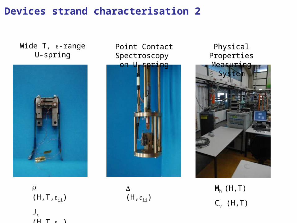
(H,T,ii)
Jc (H,T,ii)
(H,ii) Mh (H,T)
Cv (H,T)
Wide T, -rangeU-spring
Point Contact Spectroscopy on U-spring
Physical Properties Measuring System
Devices strand characterisation 2

Work package 2.56 23.7 19.5 31-dec-04
WP-HFM-1 Management and coordination
Follow -up of the progress in the technical WPsRegular reporting to EU and participants’ management (yearly report)PlanningFinancial follow up (quarterly report)
0.16 1.2 0 31-dec-04
WP-HFM-2 Support studies
1) radiation resistance of Nb3Sn certified2) radiation resistent insulation certified3) rediation resistent impregnation certified4)Heat deposition and heat removal model with experimental validation.5)Thermal coil design parameters for dipole and 0.8 12.5 7 31-dec-04
WP-HFM-3 High field dipole model
1.5 m long, 13T, 100 mm aperture model dipole magnet
0.9 4 6 31-dec-04
WP-HFM-4 Very High field dipole insert
1 solenoid insert for 100 mm bore1 dipole insert for 100 mm bore
0.4 4 4 31-mei-06
WP-HFM-5 Corrector model in Nb3Sn
short model of a single conductor wound Nb3Sn corrector
0.3 2 2.5 31-mei-06
WP-HFM-opt1High field long prototype
4 m long, 180 T/m, 130 mm aperture quadrupole magnet or4 m long, 13 T, 100 mm aperture dipole magnet
1.2 6 7 31-mei-06
WP-HFM-opt2Two-in-One high field dipole model
1 m long, 12 T bore field, 60 mm aperture two-in-one dipole model
0.7 4 5 31-mei-06

0.7
0.8
0.9
1
0 40 80 120 160 200
transMPa
Ic(
tran
s)/I
c(0)
cable 1
cable 2
cable 3
poorly impregnated cable
transverse pressure on cables
0.7
0.8
0.9
1
0 40 80 120 160 200
cable 1
cable 2
cable 3
poorly impregnated cable
reversible reduction irreversible
degradation
stress sensitivity

2000
2400
2800
3200
3600
4000
8.0 10.0 12.0 14.0
B, G/20 (T,T/m)
J (A
/mm
2 )
1.9 K4.3
5 K
6 K
9 K
8 7
100%
80%
0.01
0.10
1.00
10.00
100.00
1 10 100 1000
Qv (mW/cm3)
Tca
b-T
b (K
)
DT surface
DT insulation
DT total
q*=8000 W/m2
T
T
T
cooling at 1 minor edge only @ 1.9K
wcab = 0.02 mdiso = 0.0001 m = 0.01* T Wm-1K-1
Magnet cooling

3
Investigate (part of EU-NED):
•perforated insulation at minor edges
•radial transport in coils of He II
•heat transfer at such surfaces
He II channels
Magnet cooling (2)