Embed Size (px)
Citation preview

© KEMET Electronics Corporation • P.O. Box 5928 • Greenville, SC 29606 • 864-963-6300 • www.kemet.com F3065_F611_F612 • 9/23/2016 1One world. One KEMET
Benefits
• Voltage range: 50 – 1,000 VDC• Capacitance range: 0.001 – 180 µF • Lead spacing: 5 – 37.5 mm• Capacitance tolerance: ±10%, ±20%, ±5% on request• Climatic category: 55/105/56, IEC 60068–1• Tape and reel packaging in accordance with IEC 60286–2• RoHS Compliant and lead-free terminations• Operatingtemperaturerangeof-55˚Cto+105˚C
Overview
The F611 and F612 Series is constructed of metallized wound orstackedpolyesterfilmcapacitorwithradialleadsoftinnedwire. Radial leads are electrically welded to the contact metal layer on the ends of the capacitor winding. The capacitor is encapsulated in a self-extinguishing material meeting the requirements of UL 94 V–0.
Applications
Typical applications include blocking, coupling, decoupling, bypassing and interference suppression in low voltage applications such as automotive. Not for use with the mains.
General Purpose, Pulse and DC Transient Suppression
F611 & F612 Series Metallized Polyester Film, 5 – 37.5 mm Lead Spacing, 50 – 1,000 VDC
Part Number System
F 611 J F 104 M 050 C
Capacitor Class SeriesLead Spacing
(mm)Size Code
Capacitance Code (pF)
Capacitance Tolerance
Rated Voltage (VDC)
Packaging
F = Film Metallized Polyester 611 = Wound 612 = Stacked
J = 5 K = 7.5 A = 10.0 B = 15.0 D = 22.5 F = 27.5 R = 37.5
See Dimension Table
First two digits represent significant
figures.Thirddigitspecifies
number of zeros.
J = ±5% K = ±10% M = ±20%
050 = 50 063 = 63 100 = 100 160 = 160 250 = 250 400 = 400 630 = 630 1K0 = 1,000
See Ordering Options Table

© KEMET Electronics Corporation • P.O. Box 5928 • Greenville, SC 29606 • 864-963-6300 • www.kemet.com F3065_F611_F612 • 9/23/2016 2
Film Capacitors – General Purpose, Pulse and DC Transient Suppression F611 & F612 Series Metallized Polyester Film, 5 – 37.5 mm Lead Spacing, 50 – 1,000 VDC
Ordering Options Table
Lead SpacingNominal
(mm)Type of Leads and Packaging Lead Length
(mm)
Lead and Packaging
Code
5
Standard Lead and Packaging Options
Bulk (Bag) – Short Leads 4+2/-0 CBulk (Bag) – Long Leads 17+0/-1 ATape & Reel (Standard Reel) H0=18.5+/-0.5 L
Other Lead and Packaging Options
Bulk (Bag) – Max Length Leads 20+5/-0 ALL0LAmmo Pack H0= 18.5+/-0.5 R
7.5
Standard Lead and Packaging Options
Bulk (Bag) – Short Leads 4+2/-0 CBulk (Bag) – Long Leads 17+0/-1 ATape & Reel (Standard Reel) H0= 18.5+/-0.5 L
Other Lead and Packaging Options
Bulk (Bag) – Max Length Leads 20+5/-0 ALL0LAmmo Pack H0= 18.5+/-0.5 R
10
Standard Lead and Packaging Options
Bulk (Bag) – Short Leads 4+2/-0 CBulk (Bag) – Long Leads 17+0/-1 ATape & Reel (Standard Reel) H0= 18.5+/-0.5 L
Other Lead and Packaging Options
Bulk (Bag) – Max Length Leads 20+5/-0 ALL0LAmmo Pack H0= 18.5+/-0.5 RTape & Reel (Large Reel) H0= 18.5+/-0.5 P
15
Standard Lead and Packaging Options
Bulk (Bag) – Short Leads 4+2/-0 CBulk (Bag) – Long Leads 17+0/-1 ATape & Reel (Standard Reel) H0= 18.5+/-0.5 LPizza Pack 4+2/-0 Z
Other Lead and Packaging Options
Bulk (Bag) – Max Length Leads 25+5/-0 ALR0LAmmo Pack H0= 18.5+/-0.5 RTape & Reel (Large Reel) H0= 18.5+/-0.5 P

© KEMET Electronics Corporation • P.O. Box 5928 • Greenville, SC 29606 • 864-963-6300 • www.kemet.com F3065_F611_F612 • 9/23/2016 3
Film Capacitors – General Purpose, Pulse and DC Transient Suppression F611 & F612 Series Metallized Polyester Film, 5 – 37.5 mm Lead Spacing, 50 – 1,000 VDC
Ordering Options Table cont'd
Lead SpacingNominal
(mm)Type of Leads and Packaging Lead Length
(mm)
Lead and Packaging
Code
22.5
Standard Lead and Packaging Options
Pizza – Long Leads 17+0/-1 ZLH0JPizza Pack 4+2/-0 Z
Other Lead and Packaging Options
Tape & Reel (Standard Reel) H0= 18.5+/-0.5 LTape & Reel (Large Reel) H0= 18.5+/-0.5 PAmmo Pack H0= 18.5+/-0.5 R
27.5Standard Lead and Packaging Options
Pizza – Long Leads 17+0/-1 ZLH0JPizza Pack 4+2/-0 Z
37.5Standard Lead and Packaging Options
Pizza – Long Leads 17+0/-1 ZLH0JPizza Pack 4+2/-0 Z

© KEMET Electronics Corporation • P.O. Box 5928 • Greenville, SC 29606 • 864-963-6300 • www.kemet.com F3065_F611_F612 • 9/23/2016 4
Film Capacitors – General Purpose, Pulse and DC Transient Suppression F611 & F612 Series Metallized Polyester Film, 5 – 37.5 mm Lead Spacing, 50 – 1,000 VDC
Dimensions – Millimeters
L B
H
d
p
LL0.5
FRONT VIEW SIDE VIEW
Size Codep B H L d
Nominal Tolerance Nominal Tolerance Nominal Tolerance Nominal Tolerance Nominal Tolerance
JF 5.0 +/-0.4 2.5 Maximum 6.5 Maximum 7.2 Maximum 0.5 +/-0.05 JG 5.0 +/-0.4 3.5 Maximum 7.5 Maximum 7.2 Maximum 0.5 +/-0.05 JM 5.0 +/-0.4 4.5 Maximum 9.5 Maximum 7.2 Maximum 0.5 +/-0.05 JQ 5.0 +/-0.4 5.0 Maximum 10.0 Maximum 7.2 Maximum 0.5 +/-0.05 JT 5.0 +/-0.4 6.0 Maximum 11.0 Maximum 7.2 Maximum 0.5 +/-0.05 JU 5.0 +/-0.4 7.2 Maximum 13.0 Maximum 7.2 Maximum 0.5 +/-0.05 KE 7.5 +/-0.4 2.5 Maximum 6.0 Maximum 10.0 Maximum 0.6 +/-0.05 KF 7.5 +/-0.4 3.0 Maximum 8.0 Maximum 10.0 Maximum 0.6 +/-0.05 KG 7.5 +/-0.4 4.0 Maximum 8.0 Maximum 10.0 Maximum 0.6 +/-0.05 KH 7.5 +/-0.4 4.0 Maximum 9.0 Maximum 10.0 Maximum 0.6 +/-0.05 KJ 7.5 +/-0.4 5.0 Maximum 10.5 Maximum 10.0 Maximum 0.6 +/-0.05 KM 7.5 +/-0.4 6.0 Maximum 12.0 Maximum 10.5 Maximum 0.6 +/-0.05 AG 10.0 +/-0.4 4.0 Maximum 9.0 Maximum 13.0 Maximum 0.6 +/-0.05 AK 10.0 +/-0.4 5.0 Maximum 11.0 Maximum 13.0 Maximum 0.6 +/-0.05 AP 10.0 +/-0.4 6.0 Maximum 12.0 Maximum 13.0 Maximum 0.6 +/-0.05 BB 15.0 +/-0.4 4.0 Maximum 10.0 Maximum 18.0 Maximum 0.8 +/-0.05 BC 15.0 +/-0.4 5.0 Maximum 11.0 Maximum 18.0 Maximum 0.8 +/-0.05 BE 15.0 +/-0.4 5.5 Maximum 12.5 Maximum 18.0 Maximum 0.8 +/-0.05 BG 15.0 +/-0.4 6.0 Maximum 12.0 Maximum 18.0 Maximum 0.8 +/-0.05 BK 15.0 +/-0.4 7.5 Maximum 13.5 Maximum 18.0 Maximum 0.8 +/-0.05 BP 15.0 +/-0.4 8.5 Maximum 14.5 Maximum 18.0 Maximum 0.8 +/-0.05 BS 15.0 +/-0.4 10.0 Maximum 16.0 Maximum 18.0 Maximum 0.8 +/-0.05 BY 15.0 +/-0.4 11.0 Maximum 19.0 Maximum 18.0 Maximum 0.8 +/-0.05 DB 22.5 +/-0.4 6.0 Maximum 14.5 Maximum 26.0 Maximum 0.8 +/-0.05 DI 22.5 +/-0.4 7.0 Maximum 16.0 Maximum 26.0 Maximum 0.8 +/-0.05 DH 22.5 +/-0.4 8.0 Maximum 16.0 Maximum 26.0 Maximum 0.8 +/-0.05 DJ 22.5 +/-0.4 8.5 Maximum 17.0 Maximum 26.0 Maximum 0.8 +/-0.05 DM 22.5 +/-0.4 9.0 Maximum 18.5 Maximum 26.0 Maximum 0.8 +/-0.05 DO 22.5 +/-0.4 10.0 Maximum 18.5 Maximum 26.0 Maximum 0.8 +/-0.05
Note: See Ordering Options Table for lead length (LL) options.
© KEMET Electronics Corporation • P.O. Box 5928 • Greenville, SC 29606 • 864-963-6300 • www.kemet.com F3065_F611_F612 • 9/23/2016 5
Film Capacitors – General Purpose, Pulse and DC Transient Suppression F611 & F612 Series Metallized Polyester Film, 5 – 37.5 mm Lead Spacing, 50 – 1,000 VDC
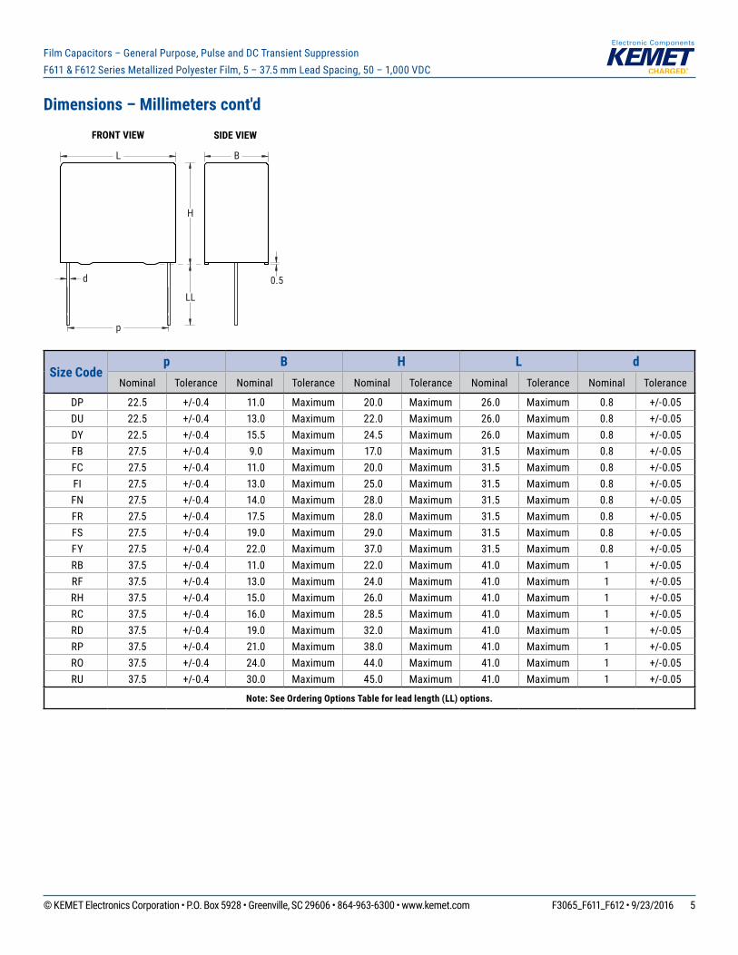
Dimensions – Millimeters cont'd
L B
H
d
p
LL0.5
FRONT VIEW SIDE VIEW
Size Codep B H L d
Nominal Tolerance Nominal Tolerance Nominal Tolerance Nominal Tolerance Nominal Tolerance
DP 22.5 +/-0.4 11.0 Maximum 20.0 Maximum 26.0 Maximum 0.8 +/-0.05 DU 22.5 +/-0.4 13.0 Maximum 22.0 Maximum 26.0 Maximum 0.8 +/-0.05 DY 22.5 +/-0.4 15.5 Maximum 24.5 Maximum 26.0 Maximum 0.8 +/-0.05 FB 27.5 +/-0.4 9.0 Maximum 17.0 Maximum 31.5 Maximum 0.8 +/-0.05 FC 27.5 +/-0.4 11.0 Maximum 20.0 Maximum 31.5 Maximum 0.8 +/-0.05 FI 27.5 +/-0.4 13.0 Maximum 25.0 Maximum 31.5 Maximum 0.8 +/-0.05 FN 27.5 +/-0.4 14.0 Maximum 28.0 Maximum 31.5 Maximum 0.8 +/-0.05 FR 27.5 +/-0.4 17.5 Maximum 28.0 Maximum 31.5 Maximum 0.8 +/-0.05 FS 27.5 +/-0.4 19.0 Maximum 29.0 Maximum 31.5 Maximum 0.8 +/-0.05 FY 27.5 +/-0.4 22.0 Maximum 37.0 Maximum 31.5 Maximum 0.8 +/-0.05 RB 37.5 +/-0.4 11.0 Maximum 22.0 Maximum 41.0 Maximum 1 +/-0.05 RF 37.5 +/-0.4 13.0 Maximum 24.0 Maximum 41.0 Maximum 1 +/-0.05 RH 37.5 +/-0.4 15.0 Maximum 26.0 Maximum 41.0 Maximum 1 +/-0.05 RC 37.5 +/-0.4 16.0 Maximum 28.5 Maximum 41.0 Maximum 1 +/-0.05 RD 37.5 +/-0.4 19.0 Maximum 32.0 Maximum 41.0 Maximum 1 +/-0.05 RP 37.5 +/-0.4 21.0 Maximum 38.0 Maximum 41.0 Maximum 1 +/-0.05 RO 37.5 +/-0.4 24.0 Maximum 44.0 Maximum 41.0 Maximum 1 +/-0.05 RU 37.5 +/-0.4 30.0 Maximum 45.0 Maximum 41.0 Maximum 1 +/-0.05
Note: See Ordering Options Table for lead length (LL) options.
© KEMET Electronics Corporation • P.O. Box 5928 • Greenville, SC 29606 • 864-963-6300 • www.kemet.com F3065_F611_F612 • 9/23/2016 6
Film Capacitors – General Purpose, Pulse and DC Transient Suppression F611 & F612 Series Metallized Polyester Film, 5 – 37.5 mm Lead Spacing, 50 – 1,000 VDC
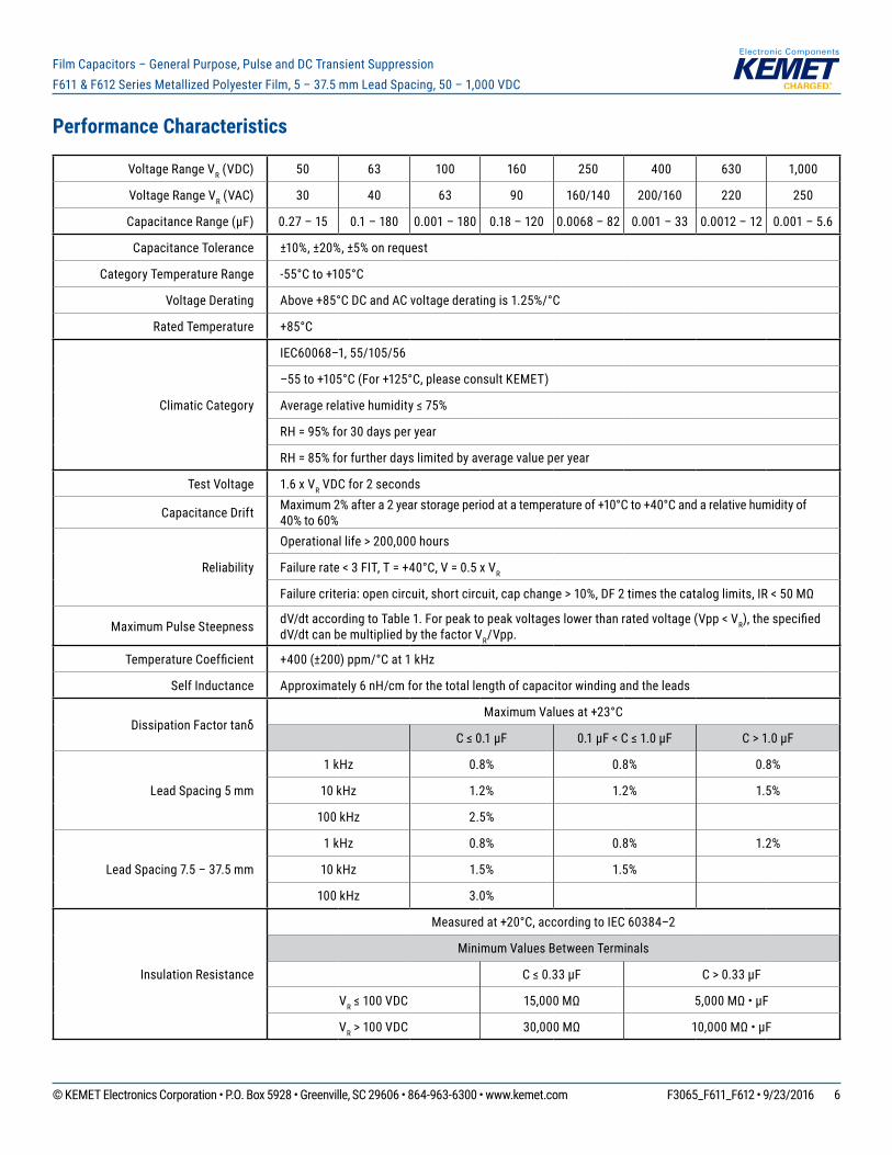
Performance Characteristics
Voltage Range VR (VDC) 50 63 100 160 250 400 630 1,000
Voltage Range VR (VAC) 30 40 63 90 160/140 200/160 220 250
Capacitance Range (µF) 0.27 – 15 0.1 – 180 0.001 – 180 0.18 – 120 0.0068 – 82 0.001 – 33 0.0012 – 12 0.001 – 5.6
Capacitance Tolerance ±10%, ±20%, ±5% on request
Category Temperature Range -55°Cto+105°C
Voltage Derating Above+85°CDCandACvoltagederatingis1.25%/°C
Rated Temperature +85°C
Climatic Category
IEC60068–1, 55/105/56
–55to+105°C(For+125°C,pleaseconsultKEMET)
Averagerelativehumidity≤75%
RH = 95% for 30 days per year
RH = 85% for further days limited by average value per year
Test Voltage 1.6 x VR VDC for 2 seconds
Capacitance Drift Maximum2%aftera2yearstorageperiodatatemperatureof+10°Cto+40°Candarelativehumidityof40% to 60%
Reliability
Operational life > 200,000 hours
Failurerate<3FIT,T=+40°C,V=0.5xVR
Failurecriteria:opencircuit,shortcircuit,capchange>10%,DF2timesthecataloglimits,IR<50MΩ
Maximum Pulse Steepness dV/dt according to Table 1. For peak to peak voltages lower than rated voltage (Vpp < VR),thespecifieddV/dt can be multiplied by the factor VR/Vpp.
TemperatureCoefficient +400(±200)ppm/°Cat1kHz
Self Inductance Approximately 6 nH/cm for the total length of capacitor winding and the leads
DissipationFactortanδMaximumValuesat+23°C
C≤0.1µF 0.1µF<C≤1.0µF C > 1.0 µF
Lead Spacing 5 mm
1 kHz 0.8% 0.8% 0.8%
10 kHz 1.2% 1.2% 1.5%
100 kHz 2.5%
Lead Spacing 7.5 – 37.5 mm
1 kHz 0.8% 0.8% 1.2%
10 kHz 1.5% 1.5%
100 kHz 3.0%
Insulation Resistance
Measuredat+20°C,accordingtoIEC60384–2
Minimum Values Between Terminals
C≤0.33µF C > 0.33 µF
VR≤100VDC 15,000MΩ 5,000MΩ•µF
VR > 100 VDC 30,000MΩ 10,000MΩ•µF
© KEMET Electronics Corporation • P.O. Box 5928 • Greenville, SC 29606 • 864-963-6300 • www.kemet.com F3065_F611_F612 • 9/23/2016 7
Film Capacitors – General Purpose, Pulse and DC Transient Suppression F611 & F612 Series Metallized Polyester Film, 5 – 37.5 mm Lead Spacing, 50 – 1,000 VDC
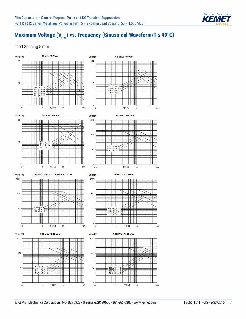
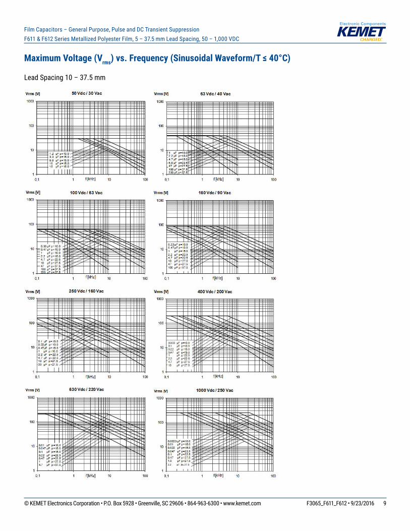
Maximum Voltage (Vrms) vs. Frequency (Sinusoidal Waveform/T ≤ 40°C)
Lead Spacing 5 mm
© KEMET Electronics Corporation • P.O. Box 5928 • Greenville, SC 29606 • 864-963-6300 • www.kemet.com F3065_F611_F612 • 9/23/2016 8
Film Capacitors – General Purpose, Pulse and DC Transient Suppression F611 & F612 Series Metallized Polyester Film, 5 – 37.5 mm Lead Spacing, 50 – 1,000 VDC
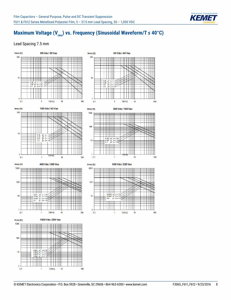
Maximum Voltage (Vrms) vs. Frequency (Sinusoidal Waveform/T ≤ 40°C)
Lead Spacing 7.5 mm
© KEMET Electronics Corporation • P.O. Box 5928 • Greenville, SC 29606 • 864-963-6300 • www.kemet.com F3065_F611_F612 • 9/23/2016 9
Film Capacitors – General Purpose, Pulse and DC Transient Suppression F611 & F612 Series Metallized Polyester Film, 5 – 37.5 mm Lead Spacing, 50 – 1,000 VDC
Maximum Voltage (Vrms) vs. Frequency (Sinusoidal Waveform/T ≤ 40°C)
Lead Spacing 10 – 37.5 mm
© KEMET Electronics Corporation • P.O. Box 5928 • Greenville, SC 29606 • 864-963-6300 • www.kemet.com F3065_F611_F612 • 9/23/2016 10
Film Capacitors – General Purpose, Pulse and DC Transient Suppression F611 & F612 Series Metallized Polyester Film, 5 – 37.5 mm Lead Spacing, 50 – 1,000 VDC
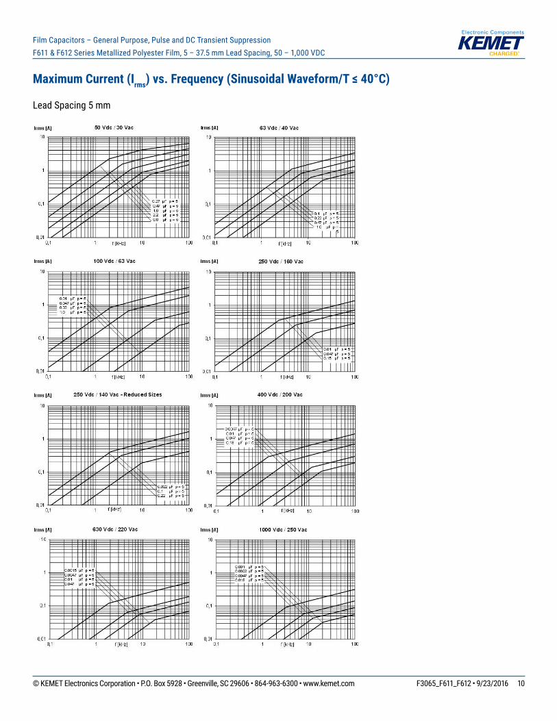
Maximum Current (Irms) vs. Frequency (Sinusoidal Waveform/T ≤ 40°C)
Lead Spacing 5 mm
© KEMET Electronics Corporation • P.O. Box 5928 • Greenville, SC 29606 • 864-963-6300 • www.kemet.com F3065_F611_F612 • 9/23/2016 11
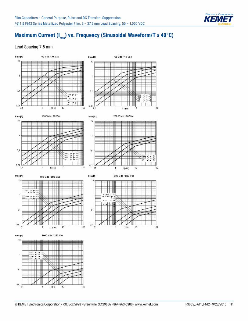
Film Capacitors – General Purpose, Pulse and DC Transient Suppression F611 & F612 Series Metallized Polyester Film, 5 – 37.5 mm Lead Spacing, 50 – 1,000 VDC
Maximum Current (Irms) vs. Frequency (Sinusoidal Waveform/T ≤ 40°C)
Lead Spacing 7.5 mm
© KEMET Electronics Corporation • P.O. Box 5928 • Greenville, SC 29606 • 864-963-6300 • www.kemet.com F3065_F611_F612 • 9/23/2016 12
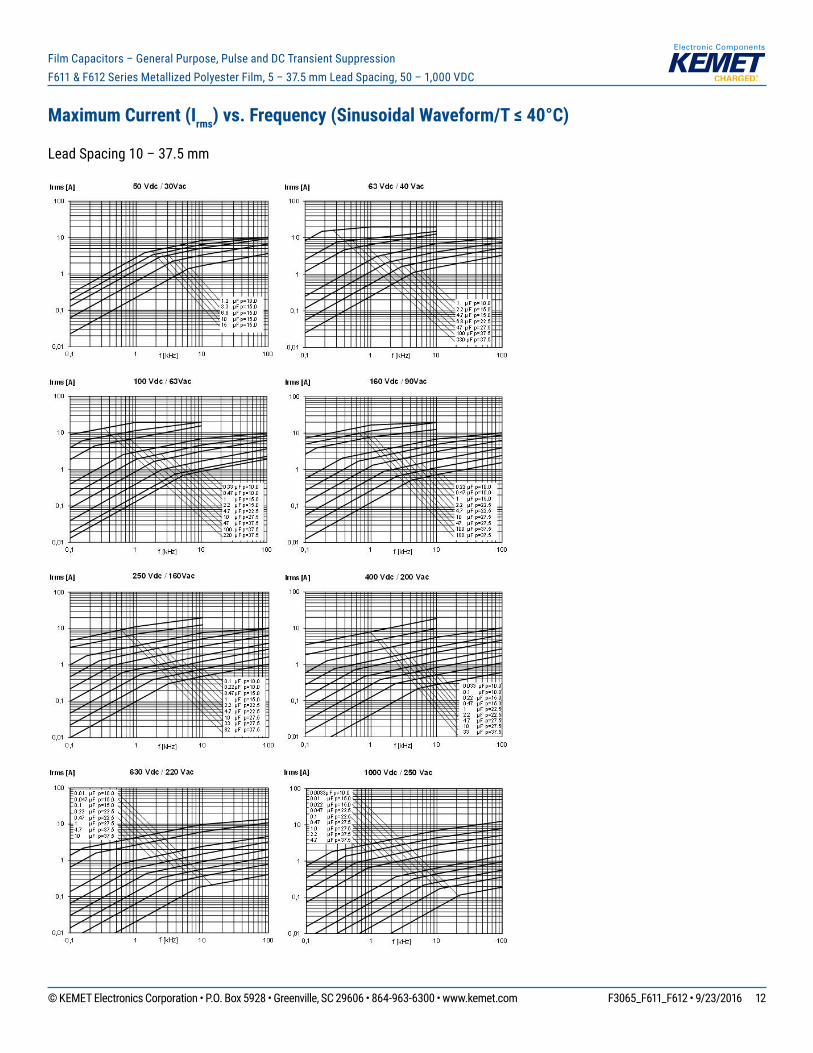
Film Capacitors – General Purpose, Pulse and DC Transient Suppression F611 & F612 Series Metallized Polyester Film, 5 – 37.5 mm Lead Spacing, 50 – 1,000 VDC
Maximum Current (Irms) vs. Frequency (Sinusoidal Waveform/T ≤ 40°C)
Lead Spacing 10 – 37.5 mm
© KEMET Electronics Corporation • P.O. Box 5928 • Greenville, SC 29606 • 864-963-6300 • www.kemet.com F3065_F611_F612 • 9/23/2016 13
Film Capacitors – General Purpose, Pulse and DC Transient Suppression F611 & F612 Series Metallized Polyester Film, 5 – 37.5 mm Lead Spacing, 50 – 1,000 VDC
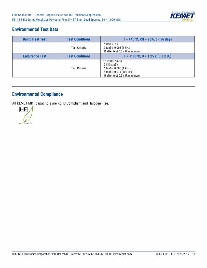
Environmental Test Data
Damp Heat Test Test Conditions T = +40°C, RH = 93%, t = 56 days
Test CriteriaΔC/C≤±5% Δtanδ≤0.005(1kHz) IR after test 0.5 x IR minimum
Endurance Test Test Conditions T = +100°C, U = 1.25 x (0.8 x UR)
Test Criteria
t = 2,000 hours ΔC/C≤±5%, Δtanδ≤0.005(1kHz) Δtanδ≤0.010(100kHz) IR after test 0.5 x IR minimum
Environmental Compliance
All KEMET MKT capacitors are RoHS Compliant and Halogen Free.
© KEMET Electronics Corporation • P.O. Box 5928 • Greenville, SC 29606 • 864-963-6300 • www.kemet.com F3065_F611_F612 • 9/23/2016 14
Film Capacitors – General Purpose, Pulse and DC Transient Suppression F611 & F612 Series Metallized Polyester Film, 5 – 37.5 mm Lead Spacing, 50 – 1,000 VDC
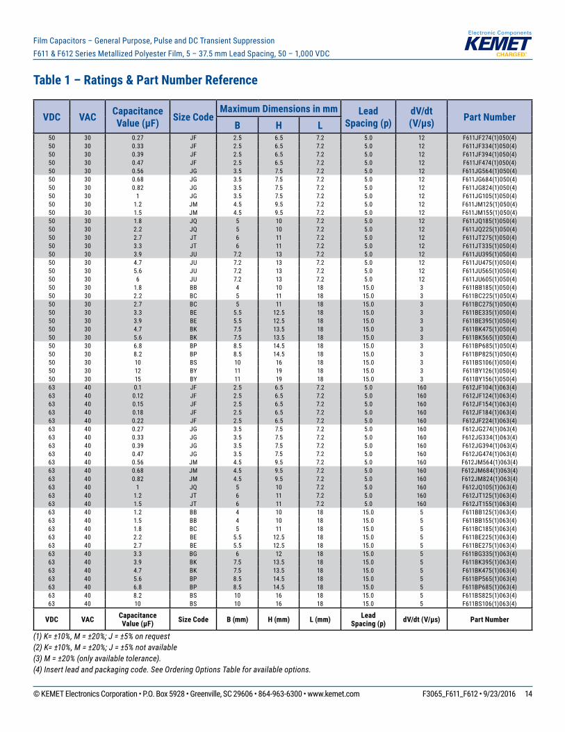
VDC VAC Capacitance Value (µF) Size Code
Maximum Dimensions in mm Lead Spacing (p)
dV/dt (V/µs) Part Number
B H L 50 30 0.27 JF 2.5 6.5 7.2 5.0 12 F611JF274(1)050(4)50 30 0.33 JF 2.5 6.5 7.2 5.0 12 F611JF334(1)050(4)50 30 0.39 JF 2.5 6.5 7.2 5.0 12 F611JF394(1)050(4)50 30 0.47 JF 2.5 6.5 7.2 5.0 12 F611JF474(1)050(4)50 30 0.56 JG 3.5 7.5 7.2 5.0 12 F611JG564(1)050(4)50 30 0.68 JG 3.5 7.5 7.2 5.0 12 F611JG684(1)050(4)50 30 0.82 JG 3.5 7.5 7.2 5.0 12 F611JG824(1)050(4)50 30 1 JG 3.5 7.5 7.2 5.0 12 F611JG105(1)050(4)50 30 1.2 JM 4.5 9.5 7.2 5.0 12 F611JM125(1)050(4)50 30 1.5 JM 4.5 9.5 7.2 5.0 12 F611JM155(1)050(4)50 30 1.8 JQ 5 10 7.2 5.0 12 F611JQ185(1)050(4)50 30 2.2 JQ 5 10 7.2 5.0 12 F611JQ225(1)050(4)50 30 2.7 JT 6 11 7.2 5.0 12 F611JT275(1)050(4)50 30 3.3 JT 6 11 7.2 5.0 12 F611JT335(1)050(4)50 30 3.9 JU 7.2 13 7.2 5.0 12 F611JU395(1)050(4)50 30 4.7 JU 7.2 13 7.2 5.0 12 F611JU475(1)050(4)50 30 5.6 JU 7.2 13 7.2 5.0 12 F611JU565(1)050(4)50 30 6 JU 7.2 13 7.2 5.0 12 F611JU605(1)050(4)50 30 1.8 BB 4 10 18 15.0 3 F611BB185(1)050(4)50 30 2.2 BC 5 11 18 15.0 3 F611BC225(1)050(4)50 30 2.7 BC 5 11 18 15.0 3 F611BC275(1)050(4)50 30 3.3 BE 5.5 12.5 18 15.0 3 F611BE335(1)050(4)50 30 3.9 BE 5.5 12.5 18 15.0 3 F611BE395(1)050(4)50 30 4.7 BK 7.5 13.5 18 15.0 3 F611BK475(1)050(4)50 30 5.6 BK 7.5 13.5 18 15.0 3 F611BK565(1)050(4)50 30 6.8 BP 8.5 14.5 18 15.0 3 F611BP685(1)050(4)50 30 8.2 BP 8.5 14.5 18 15.0 3 F611BP825(1)050(4)50 30 10 BS 10 16 18 15.0 3 F611BS106(1)050(4)50 30 12 BY 11 19 18 15.0 3 F611BY126(1)050(4)50 30 15 BY 11 19 18 15.0 3 F611BY156(1)050(4)63 40 0.1 JF 2.5 6.5 7.2 5.0 160 F612JF104(1)063(4)63 40 0.12 JF 2.5 6.5 7.2 5.0 160 F612JF124(1)063(4)63 40 0.15 JF 2.5 6.5 7.2 5.0 160 F612JF154(1)063(4)63 40 0.18 JF 2.5 6.5 7.2 5.0 160 F612JF184(1)063(4)63 40 0.22 JF 2.5 6.5 7.2 5.0 160 F612JF224(1)063(4)63 40 0.27 JG 3.5 7.5 7.2 5.0 160 F612JG274(1)063(4)63 40 0.33 JG 3.5 7.5 7.2 5.0 160 F612JG334(1)063(4)63 40 0.39 JG 3.5 7.5 7.2 5.0 160 F612JG394(1)063(4)63 40 0.47 JG 3.5 7.5 7.2 5.0 160 F612JG474(1)063(4)63 40 0.56 JM 4.5 9.5 7.2 5.0 160 F612JM564(1)063(4)63 40 0.68 JM 4.5 9.5 7.2 5.0 160 F612JM684(1)063(4)63 40 0.82 JM 4.5 9.5 7.2 5.0 160 F612JM824(1)063(4)63 40 1 JQ 5 10 7.2 5.0 160 F612JQ105(1)063(4)63 40 1.2 JT 6 11 7.2 5.0 160 F612JT125(1)063(4)63 40 1.5 JT 6 11 7.2 5.0 160 F612JT155(1)063(4)63 40 1.2 BB 4 10 18 15.0 5 F611BB125(1)063(4)63 40 1.5 BB 4 10 18 15.0 5 F611BB155(1)063(4)63 40 1.8 BC 5 11 18 15.0 5 F611BC185(1)063(4)63 40 2.2 BE 5.5 12.5 18 15.0 5 F611BE225(1)063(4)63 40 2.7 BE 5.5 12.5 18 15.0 5 F611BE275(1)063(4)63 40 3.3 BG 6 12 18 15.0 5 F611BG335(1)063(4)63 40 3.9 BK 7.5 13.5 18 15.0 5 F611BK395(1)063(4)63 40 4.7 BK 7.5 13.5 18 15.0 5 F611BK475(1)063(4)63 40 5.6 BP 8.5 14.5 18 15.0 5 F611BP565(1)063(4)63 40 6.8 BP 8.5 14.5 18 15.0 5 F611BP685(1)063(4)63 40 8.2 BS 10 16 18 15.0 5 F611BS825(1)063(4)63 40 10 BS 10 16 18 15.0 5 F611BS106(1)063(4)
VDC VAC Capacitance Value (µF) Size Code B (mm) H (mm) L (mm) Lead
Spacing (p) dV/dt (V/µs) Part Number
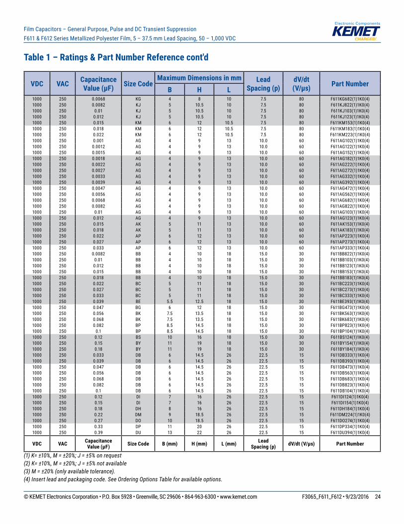
Table 1 – Ratings & Part Number Reference
(1) K= ±10%, M = ±20%; J = ±5% on request(2) K= ±10%, M = ±20%; J = ±5% not available(3) M = ±20% (only available tolerance).(4) Insert lead and packaging code. See Ordering Options Table for available options.

© KEMET Electronics Corporation • P.O. Box 5928 • Greenville, SC 29606 • 864-963-6300 • www.kemet.com F3065_F611_F612 • 9/23/2016 15
Film Capacitors – General Purpose, Pulse and DC Transient Suppression F611 & F612 Series Metallized Polyester Film, 5 – 37.5 mm Lead Spacing, 50 – 1,000 VDC
VDC VAC Capacitance Value (µF) Size Code
Maximum Dimensions in mm Lead Spacing (p)
dV/dt (V/µs) Part Number
B H L 63 40 12 BY 11 19 18 15.0 5 F611BY126(1)063(4)63 40 4.7 DB 6 14.5 26 22.5 3 F611DB475(1)063(4)63 40 5.6 DB 6 14.5 26 22.5 3 F611DB565(1)063(4)63 40 6.8 DI 7 16 26 22.5 3 F611DI685(1)063(4)63 40 8.2 DI 7 16 26 22.5 3 F611DI825(1)063(4)63 40 10 DJ 8.5 17 26 22.5 3 F611DJ106(1)063(4)63 40 12 DM 9 18.5 26 22.5 3 F611DM126(1)063(4)63 40 15 DO 10 18.5 26 22.5 3 F611DO156(1)063(4)63 40 18 DP 11 20 26 22.5 3 F611DP186(1)063(4)63 40 22 DU 13 22 26 22.5 3 F611DU226(1)063(4)63 40 27 DY 15.5 24.5 26 22.5 3 F611DY276(1)063(4)63 40 33 DY 15.5 24.5 26 22.5 3 F611DY336(1)063(4)63 40 15 FB 9 17 31.5 27.5 2 F611FB156(3)063(4)63 40 18 FC 11 20 31.5 27.5 2 F611FC186(1)063(4)63 40 22 FC 11 20 31.5 27.5 2 F611FC226(3)063(4)63 40 27 FI 13 25 31.5 27.5 2 F611FI276(1)063(4)63 40 33 FI 13 25 31.5 27.5 2 F611FI336(3)063(4)63 40 39 FN 14 28 31.5 27.5 2 F611FN396(2)063(4)63 40 47 FR 17.5 28 31.5 27.5 2 F611FR476(2)063(4)63 40 56 FS 19 29 31.5 27.5 2 F611FS566(2)063(4)63 40 68 FY 22 37 31.5 27.5 2 F611FY686(1)063(4)63 40 82 FY 22 37 31.5 27.5 2 F611FY826(1)063(4)63 40 100 FY 22 37 31.5 27.5 2 F611FY107(3)063(4)63 40 22 RB 11 22 41 37.5 1 F611RB226(1)063(4)63 40 27 RB 11 22 41 37.5 1 F611RB276(2)063(4)63 40 33 RF 13 24 41 37.5 1 F611RF336(1)063(4)63 40 39 RH 15 26 41 37.5 1 F611RH396(1)063(4)63 40 47 RH 15 26 41 37.5 1 F611RH476(2)063(4)63 40 56 RC 16 28.5 41 37.5 1 F611RC566(2)063(4)63 40 68 RD 19 32 41 37.5 1 F611RD686(1)063(4)63 40 82 RP 21 38 41 37.5 1 F611RP826(1)063(4)63 40 100 RP 21 38 41 37.5 1 F611RP107(2)063(4)63 40 120 RO 24 44 41 37.5 1 F611RO127(1)063(4)63 40 150 RO 24 44 41 37.5 1 F611RO157(2)063(4)63 40 180 RU 30 45 41 37.5 1 F611RU187(2)063(4)
100 63 0.001 JF 2.5 6.5 7.2 5.0 200 F612JF102(1)100(4)100 63 0.0012 JF 2.5 6.5 7.2 5.0 200 F612JF122(1)100(4)100 63 0.0015 JF 2.5 6.5 7.2 5.0 200 F612JF152(1)100(4)100 63 0.0018 JF 2.5 6.5 7.2 5.0 200 F612JF182(1)100(4)100 63 0.0022 JF 2.5 6.5 7.2 5.0 200 F612JF222(1)100(4)100 63 0.0027 JF 2.5 6.5 7.2 5.0 200 F612JF272(1)100(4)100 63 0.0033 JF 2.5 6.5 7.2 5.0 200 F612JF332(1)100(4)100 63 0.0039 JF 2.5 6.5 7.2 5.0 200 F612JF392(1)100(4)100 63 0.0047 JF 2.5 6.5 7.2 5.0 200 F612JF472(1)100(4)100 63 0.0056 JF 2.5 6.5 7.2 5.0 200 F612JF562(1)100(4)100 63 0.0068 JF 2.5 6.5 7.2 5.0 200 F612JF682(1)100(4)100 63 0.0082 JF 2.5 6.5 7.2 5.0 200 F612JF822(1)100(4)100 63 0.01 JF 2.5 6.5 7.2 5.0 200 F612JF103(1)100(4)100 63 0.012 JF 2.5 6.5 7.2 5.0 200 F612JF123(1)100(4)100 63 0.015 JF 2.5 6.5 7.2 5.0 200 F612JF153(1)100(4)100 63 0.018 JF 2.5 6.5 7.2 5.0 200 F612JF183(1)100(4)100 63 0.022 JF 2.5 6.5 7.2 5.0 200 F612JF223(1)100(4)100 63 0.027 JF 2.5 6.5 7.2 5.0 200 F612JF273(1)100(4)100 63 0.033 JF 2.5 6.5 7.2 5.0 200 F612JF333(1)100(4)100 63 0.039 JF 2.5 6.5 7.2 5.0 200 F612JF393(1)100(4)100 63 0.047 JF 2.5 6.5 7.2 5.0 200 F612JF473(1)100(4)100 63 0.056 JF 2.5 6.5 7.2 5.0 200 F612JF563(1)100(4)
VDC VAC Capacitance Value (µF) Size Code B (mm) H (mm) L (mm) Lead
Spacing (p) dV/dt (V/µs) Part Number
Table 1 – Ratings & Part Number Reference cont'd
(1) K= ±10%, M = ±20%; J = ±5% on request(2) K= ±10%, M = ±20%; J = ±5% not available(3) M = ±20% (only available tolerance).(4) Insert lead and packaging code. See Ordering Options Table for available options.

© KEMET Electronics Corporation • P.O. Box 5928 • Greenville, SC 29606 • 864-963-6300 • www.kemet.com F3065_F611_F612 • 9/23/2016 16
Film Capacitors – General Purpose, Pulse and DC Transient Suppression F611 & F612 Series Metallized Polyester Film, 5 – 37.5 mm Lead Spacing, 50 – 1,000 VDC
VDC VAC Capacitance Value (µF) Size Code
Maximum Dimensions in mm Lead Spacing (p)
dV/dt (V/µs) Part Number
B H L 100 63 0.068 JF 2.5 6.5 7.2 5.0 200 F612JF683(1)100(4)100 63 0.082 JF 2.5 6.5 7.2 5.0 200 F612JF823(1)100(4)100 63 0.1 JF 2.5 6.5 7.2 5.0 200 F612JF104(1)100(4)100 63 0.12 JF 2.5 6.5 7.2 5.0 200 F612JF124(1)100(4)100 63 0.15 JG 3.5 7.5 7.2 5.0 200 F612JG154(1)100(4)100 63 0.18 JG 3.5 7.5 7.2 5.0 200 F612JG184(1)100(4)100 63 0.22 JG 3.5 7.5 7.2 5.0 200 F612JG224(1)100(4)100 63 0.27 JG 3.5 7.5 7.2 5.0 200 F612JG274(1)100(4)100 63 0.33 JM 4.5 9.5 7.2 5.0 200 F612JM334(1)100(4)100 63 0.39 JM 4.5 9.5 7.2 5.0 200 F612JM394(1)100(4)100 63 0.47 JM 4.5 9.5 7.2 5.0 200 F612JM474(1)100(4)100 63 0.56 JQ 5 10 7.2 5.0 200 F612JQ564(1)100(4)100 63 0.68 JQ 5 10 7.2 5.0 200 F612JQ684(1)100(4)100 63 0.82 JT 6 11 7.2 5.0 200 F612JT824(1)100(4)100 63 1 JT 6 11 7.2 5.0 200 F612JT105(1)100(4)100 63 0.56 BB 4 10 18 15.0 8 F611BB564(1)100(4)100 63 0.68 BB 4 10 18 15.0 8 F611BB684(1)100(4)100 63 0.82 BB 4 10 18 15.0 8 F611BB824(1)100(4)100 63 1 BB 4 10 18 15.0 8 F611BB105(1)100(4)100 63 1.2 BC 5 11 18 15.0 8 F611BC125(1)100(4)100 63 1.5 BC 5 11 18 15.0 8 F611BC155(1)100(4)100 63 1.8 BE 5.5 12.5 18 15.0 8 F611BE185(1)100(4)100 63 2.2 BG 6 12 18 15.0 8 F611BG225(1)100(4)100 63 2.7 BK 7.5 13.5 18 15.0 8 F611BK275(1)100(4)100 63 3.3 BK 7.5 13.5 18 15.0 8 F611BK335(1)100(4)100 63 3.9 BP 8.5 14.5 18 15.0 8 F611BP395(1)100(4)100 63 4.7 BP 8.5 14.5 18 15.0 8 F611BP475(1)100(4)100 63 5.6 BS 10 16 18 15.0 8 F611BS565(1)100(4)100 63 6.8 BY 11 19 18 15.0 8 F611BY685(1)100(4)100 63 8.2 BY 11 19 18 15.0 8 F611BY825(1)100(4)100 63 2.2 DB 6 14.5 26 22.5 5 F611DB225(1)100(4)100 63 2.7 DB 6 14.5 26 22.5 5 F611DB275(1)100(4)100 63 3.3 DB 6 14.5 26 22.5 5 F611DB335(1)100(4)100 63 3.9 DB 6 14.5 26 22.5 5 F611DB395(1)100(4)100 63 4.7 DI 7 16 26 22.5 5 F611DI475(1)100(4)100 63 5.6 DI 7 16 26 22.5 5 F611DI565(1)100(4)100 63 6.8 DH 8 16 26 22.5 5 F611DH685(1)100(4)100 63 8.2 DJ 8.5 17 26 22.5 5 F611DJ825(1)100(4)100 63 10 DM 9 18.5 26 22.5 5 F611DM106(1)100(4)100 63 12 DO 10 18.5 26 22.5 5 F611DO126(1)100(4)100 63 15 DP 11 20 26 22.5 5 F611DP156(1)100(4)100 63 18 DU 13 22 26 22.5 5 F611DU186(1)100(4)100 63 22 DY 15.5 24.5 26 22.5 5 F611DY226(1)100(4)100 63 27 DY 15.5 24.5 26 22.5 5 F611DY276(1)100(4)100 63 10 FB 9 17 31.5 27.5 3 F611FB106(1)100(4)100 63 12 FB 9 17 31.5 27.5 3 F611FB126(2)100(4)100 63 15 FC 11 20 31.5 27.5 3 F611FC156(1)100(4)100 63 18 FC 11 20 31.5 27.5 3 F611FC186(2)100(4)100 63 22 FI 13 25 31.5 27.5 3 F611FI226(1)100(4)100 63 27 FI 13 25 31.5 27.5 3 F611FI276(2)100(4)100 63 33 FN 14 28 31.5 27.5 3 F611FN336(2)100(4)100 63 39 FR 17.5 28 31.5 27.5 3 F611FR396(2)100(4)100 63 47 FS 19 29 31.5 27.5 3 F611FS476(2)100(4)100 63 56 FY 22 37 31.5 27.5 3 F611FY566(1)100(4)100 63 68 FY 22 37 31.5 27.5 3 F611FY686(1)100(4)100 63 82 FY 22 37 31.5 27.5 3 F611FY826(3)100(4)100 63 22 RB 11 22 41 37.5 2 F611RB226(1)100(4)
VDC VAC Capacitance Value (µF) Size Code B (mm) H (mm) L (mm) Lead
Spacing (p) dV/dt (V/µs) Part Number
Table 1 – Ratings & Part Number Reference cont'd
(1) K= ±10%, M = ±20%; J = ±5% on request(2) K= ±10%, M = ±20%; J = ±5% not available(3) M = ±20% (only available tolerance).(4) Insert lead and packaging code. See Ordering Options Table for available options.

© KEMET Electronics Corporation • P.O. Box 5928 • Greenville, SC 29606 • 864-963-6300 • www.kemet.com F3065_F611_F612 • 9/23/2016 17
Film Capacitors – General Purpose, Pulse and DC Transient Suppression F611 & F612 Series Metallized Polyester Film, 5 – 37.5 mm Lead Spacing, 50 – 1,000 VDC
VDC VAC Capacitance Value (µF) Size Code
Maximum Dimensions in mm Lead Spacing (p)
dV/dt (V/µs) Part Number
B H L 100 63 27 RB 11 22 41 37.5 2 F611RB276(2)100(4)100 63 33 RF 13 24 41 37.5 2 F611RF336(1)100(4)100 63 39 RH 15 26 41 37.5 2 F611RH396(1)100(4)100 63 47 RH 15 26 41 37.5 2 F611RH476(2)100(4)100 63 56 RC 16 28.5 41 37.5 2 F611RC566(2)100(4)100 63 68 RD 19 32 41 37.5 2 F611RD686(1)100(4)100 63 82 RP 21 38 41 37.5 2 F611RP826(1)100(4)100 63 100 RP 21 38 41 37.5 2 F611RP107(2)100(4)100 63 120 RO 24 44 41 37.5 2 F611RO127(1)100(4)100 63 150 RO 24 44 41 37.5 2 F611RO157(2)100(4)100 63 180 RU 30 45 41 37.5 2 F611RU187(2)100(4)160 90 0.33 BB 4 10 18 15.0 10 F611BB334(1)160(4)160 90 0.39 BB 4 10 18 15.0 10 F611BB394(1)160(4)160 90 0.47 BC 5 11 18 15.0 10 F611BC474(1)160(4)160 90 0.56 BC 5 11 18 15.0 10 F611BC564(1)160(4)160 90 0.68 BC 5 11 18 15.0 10 F611BC684(1)160(4)160 90 0.82 BE 5.5 12.5 18 15.0 10 F611BE824(1)160(4)160 90 1 BG 6 12 18 15.0 10 F611BG105(1)160(4)160 90 1.2 BK 7.5 13.5 18 15.0 10 F611BK125(1)160(4)160 90 1.5 BK 7.5 13.5 18 15.0 10 F611BK155(1)160(4)160 90 1.8 BP 8.5 14.5 18 15.0 10 F611BP185(1)160(4)160 90 2.2 BS 10 16 18 15.0 10 F611BS225(1)160(4)160 90 2.7 BY 11 19 18 15.0 10 F611BY275(1)160(4)160 90 3.3 BY 11 19 18 15.0 10 F611BY335(1)160(4)160 90 3.9 BY 11 19 18 15.0 10 F611BY395(1)160(4)160 90 1.2 DB 6 14.5 26 22.5 6 F611DB125(1)160(4)160 90 1.5 DB 6 14.5 26 22.5 6 F611DB155(1)160(4)160 90 1.8 DB 6 14.5 26 22.5 6 F611DB185(1)160(4)160 90 2.2 DI 7 16 26 22.5 6 F611DI225(1)160(4)160 90 2.7 DI 7 16 26 22.5 6 F611DI275(1)160(4)160 90 3.3 DJ 8.5 17 26 22.5 6 F611DJ335(1)160(4)160 90 3.9 DM 9 18.5 26 22.5 6 F611DM395(1)160(4)160 90 4.7 DO 10 18.5 26 22.5 6 F611DO475(1)160(4)160 90 5.6 DP 11 20 26 22.5 6 F611DP565(1)160(4)160 90 6.8 DU 13 22 26 22.5 6 F611DU685(1)160(4)160 90 8.2 DU 13 22 26 22.5 6 F611DU825(1)160(4)160 90 10 DY 15.5 24.5 26 22.5 6 F611DY106(1)160(4)160 90 12 DY 15.5 24.5 26 22.5 6 F611DY126(1)160(4)160 90 5.6 FB 9 17 31.5 27.5 4 F611FB565(1)160(4)160 90 6.8 FB 9 17 31.5 27.5 4 F611FB685(1)160(4)160 90 8.2 FB 9 17 31.5 27.5 4 F611FB825(3)160(4)160 90 10 FC 11 20 31.5 27.5 4 F611FC106(1)160(4)160 90 12 FC 11 20 31.5 27.5 4 F611FC126(3)160(4)160 90 15 FI 13 25 31.5 27.5 4 F611FI156(1)160(4)160 90 18 FI 13 25 31.5 27.5 4 F611FI186(2)160(4)160 90 22 FN 14 28 31.5 27.5 4 F611FN226(2)160(4)160 90 27 FR 17.5 28 31.5 27.5 4 F611FR276(2)160(4)160 90 33 FS 19 29 31.5 27.5 4 F611FS336(2)160(4)160 90 39 FY 22 37 31.5 27.5 4 F611FY396(1)160(4)160 90 47 FY 22 37 31.5 27.5 4 F611FY476(2)160(4)160 90 56 FY 22 37 31.5 27.5 4 F611FY566(3)160(4)160 90 15 RB 11 22 41 37.5 3 F611RB156(1)160(4)160 90 18 RB 11 22 41 37.5 3 F611RB186(3)160(4)160 90 22 RF 13 24 41 37.5 3 F611RF226(2)160(4)160 90 27 RH 15 26 41 37.5 3 F611RH276(1)160(4)160 90 33 RH 15 26 41 37.5 3 F611RH336(3)160(4)160 90 39 RC 16 28.5 41 37.5 3 F611RC396(3)160(4)
VDC VAC Capacitance Value (µF) Size Code B (mm) H (mm) L (mm) Lead
Spacing (p) dV/dt (V/µs) Part Number
Table 1 – Ratings & Part Number Reference cont'd
(1) K= ±10%, M = ±20%; J = ±5% on request(2) K= ±10%, M = ±20%; J = ±5% not available(3) M = ±20% (only available tolerance).(4) Insert lead and packaging code. See Ordering Options Table for available options.
© KEMET Electronics Corporation • P.O. Box 5928 • Greenville, SC 29606 • 864-963-6300 • www.kemet.com F3065_F611_F612 • 9/23/2016 18
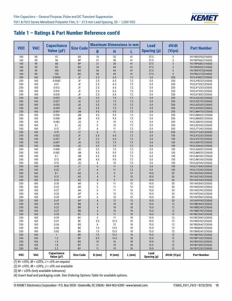
Film Capacitors – General Purpose, Pulse and DC Transient Suppression F611 & F612 Series Metallized Polyester Film, 5 – 37.5 mm Lead Spacing, 50 – 1,000 VDC
VDC VAC Capacitance Value (µF) Size Code
Maximum Dimensions in mm Lead Spacing (p)
dV/dt (V/µs) Part Number
B H L 160 90 47 RD 19 32 41 37.5 3 F611RD476(2)160(4)160 90 56 RP 21 38 41 37.5 3 F611RP566(1)160(4)160 90 68 RP 21 38 41 37.5 3 F611RP686(1)160(4)160 90 82 RO 24 44 41 37.5 3 F611RO826(1)160(4)160 90 100 RO 24 44 41 37.5 3 F611RO107(3)160(4)160 90 120 RU 30 45 41 37.5 3 F611RU127(3)160(4)250 160 0.0068 JF 2.5 6.5 7.2 5.0 250 F612JF682(1)250(4)250 160 0.0082 JF 2.5 6.5 7.2 5.0 250 F612JF822(1)250(4)250 160 0.01 JF 2.5 6.5 7.2 5.0 250 F612JF103(1)250(4)250 160 0.012 JF 2.5 6.5 7.2 5.0 250 F612JF123(1)250(4)250 160 0.015 JF 2.5 6.5 7.2 5.0 250 F612JF153(1)250(4)250 160 0.018 JF 2.5 6.5 7.2 5.0 250 F612JF183(1)250(4)250 160 0.022 JG 3.5 7.5 7.2 5.0 250 F612JG223(1)250(4)250 160 0.027 JG 3.5 7.5 7.2 5.0 250 F612JG273(1)250(4)250 160 0.033 JG 3.5 7.5 7.2 5.0 250 F612JG333(1)250(4)250 160 0.039 JG 3.5 7.5 7.2 5.0 250 F612JG393(1)250(4)250 160 0.047 JM 4.5 9.5 7.2 5.0 250 F612JM473(1)250(4)250 160 0.056 JM 4.5 9.5 7.2 5.0 250 F612JM563(1)250(4)250 160 0.068 JM 4.5 9.5 7.2 5.0 250 F612JM683(1)250(4)250 160 0.082 JQ 5 10 7.2 5.0 250 F612JQ823(1)250(4)250 160 0.1 JQ 5 10 7.2 5.0 250 F612JQ104(1)250(4)250 160 0.12 JT 6 11 7.2 5.0 250 F612JT124(1)250(4)250 160 0.15 JT 6 11 7.2 5.0 250 F612JT154(1)250(4)250 140 0.022 JF 2.5 6.5 7.2 5.0 130 F612JF223(1)250(4)250 140 0.027 JF 2.5 6.5 7.2 5.0 130 F612JF273(1)250(4)250 140 0.047 JG 3.5 7.5 7.2 5.0 130 F612JG473(1)250(4)250 140 0.056 JG 3.5 7.5 7.2 5.0 130 F612JG563(1)250(4)250 140 0.068 JG 3.5 7.5 7.2 5.0 130 F612JG683(1)250(4)250 140 0.082 JM 4.5 9.5 7.2 5.0 130 F612JM823(1)250(4)250 140 0.1 JM 4.5 9.5 7.2 5.0 130 F612JM104(1)250(4)250 140 0.12 JM 4.5 9.5 7.2 5.0 130 F612JM124(1)250(4)250 140 0.15 JQ 5 10 7.2 5.0 130 F612JQ154(1)250(4)250 140 0.18 JT 6 11 7.2 5.0 130 F612JT184(1)250(4)250 140 0.22 JT 6 11 7.2 5.0 130 F612JT224(1)250(4)250 160 0.1 AG 4 9 13 10.0 20 F611AG104(1)250(4)250 160 0.12 AG 4 9 13 10.0 20 F611AG124(1)250(4)250 160 0.15 AG 4 9 13 10.0 20 F611AG154(1)250(4)250 160 0.18 AK 5 11 13 10.0 20 F611AK184(1)250(4)250 160 0.22 AK 5 11 13 10.0 20 F611AK224(1)250(4)250 160 0.27 AK 5 11 13 10.0 20 F611AK274(1)250(4)250 160 0.33 AP 6 12 13 10.0 20 F611AP334(1)250(4)250 160 0.39 AP 6 12 13 10.0 20 F611AP394(1)250(4)250 160 0.47 AP 6 12 13 10.0 20 F611AP474(1)250(4)250 160 0.18 BB 4 10 18 15.0 12 F611BB184(1)250(4)250 160 0.22 BB 4 10 18 15.0 12 F611BB224(1)250(4)250 160 0.27 BB 4 10 18 15.0 12 F611BB274(1)250(4)250 160 0.33 BC 5 11 18 15.0 12 F611BC334(1)250(4)250 160 0.39 BC 5 11 18 15.0 12 F611BC394(1)250(4)250 160 0.47 BE 5.5 12.5 18 15.0 12 F611BE474(1)250(4)250 160 0.56 BG 6 12 18 15.0 12 F611BG564(1)250(4)250 160 0.68 BK 7.5 13.5 18 15.0 12 F611BK684(1)250(4)250 160 0.82 BK 7.5 13.5 18 15.0 12 F611BK824(1)250(4)250 160 1 BK 7.5 13.5 18 15.0 12 F611BK105(1)250(4)250 160 1.2 BP 8.5 14.5 18 15.0 12 F611BP125(1)250(4)250 160 1.5 BS 10 16 18 15.0 12 F611BS155(1)250(4)250 160 1.8 BY 11 19 18 15.0 12 F611BY185(1)250(4)250 160 2.2 BY 11 19 18 15.0 12 F611BY225(1)250(4)
VDC VAC Capacitance Value (µF) Size Code B (mm) H (mm) L (mm) Lead
Spacing (p) dV/dt (V/µs) Part Number
Table 1 – Ratings & Part Number Reference cont'd
(1) K= ±10%, M = ±20%; J = ±5% on request(2) K= ±10%, M = ±20%; J = ±5% not available(3) M = ±20% (only available tolerance).(4) Insert lead and packaging code. See Ordering Options Table for available options.
© KEMET Electronics Corporation • P.O. Box 5928 • Greenville, SC 29606 • 864-963-6300 • www.kemet.com F3065_F611_F612 • 9/23/2016 19
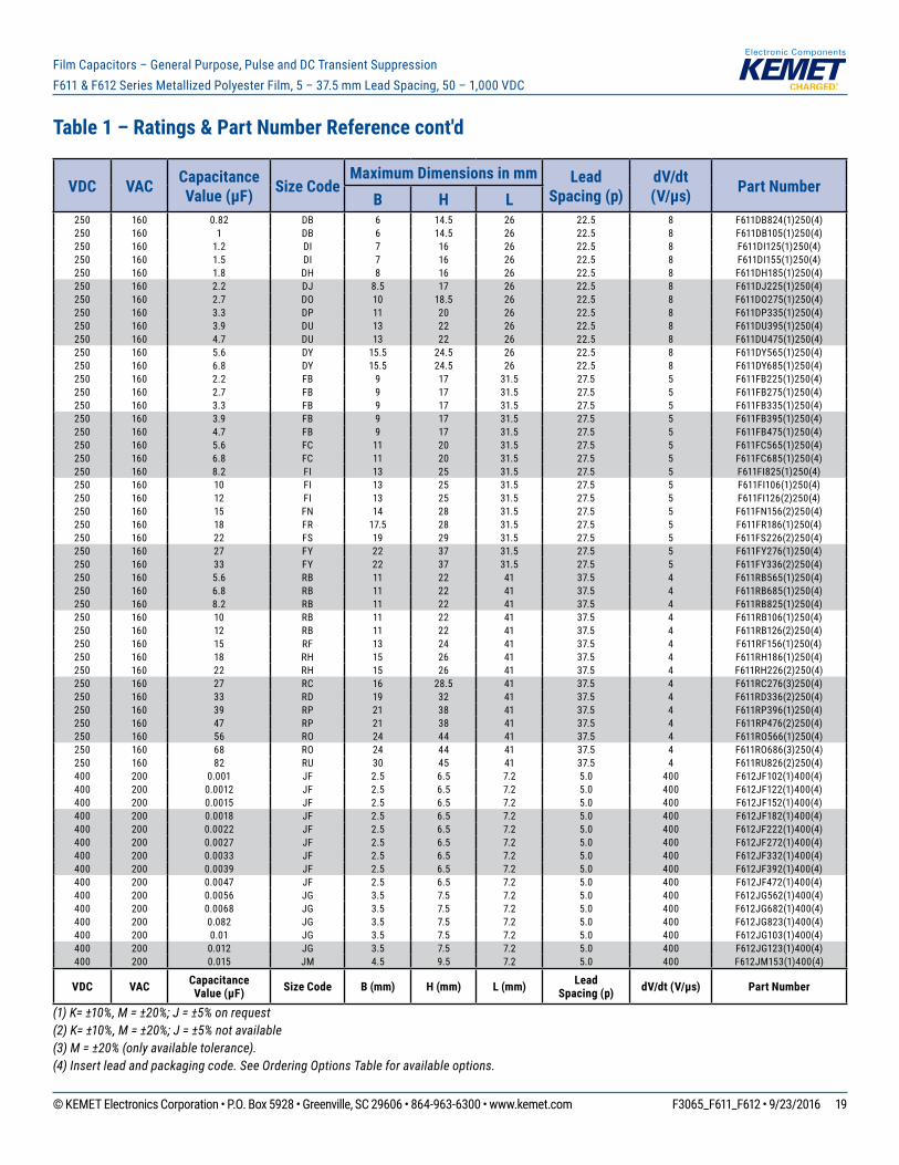
Film Capacitors – General Purpose, Pulse and DC Transient Suppression F611 & F612 Series Metallized Polyester Film, 5 – 37.5 mm Lead Spacing, 50 – 1,000 VDC
VDC VAC Capacitance Value (µF) Size Code
Maximum Dimensions in mm Lead Spacing (p)
dV/dt (V/µs) Part Number
B H L 250 160 0.82 DB 6 14.5 26 22.5 8 F611DB824(1)250(4)250 160 1 DB 6 14.5 26 22.5 8 F611DB105(1)250(4)250 160 1.2 DI 7 16 26 22.5 8 F611DI125(1)250(4)250 160 1.5 DI 7 16 26 22.5 8 F611DI155(1)250(4)250 160 1.8 DH 8 16 26 22.5 8 F611DH185(1)250(4)250 160 2.2 DJ 8.5 17 26 22.5 8 F611DJ225(1)250(4)250 160 2.7 DO 10 18.5 26 22.5 8 F611DO275(1)250(4)250 160 3.3 DP 11 20 26 22.5 8 F611DP335(1)250(4)250 160 3.9 DU 13 22 26 22.5 8 F611DU395(1)250(4)250 160 4.7 DU 13 22 26 22.5 8 F611DU475(1)250(4)250 160 5.6 DY 15.5 24.5 26 22.5 8 F611DY565(1)250(4)250 160 6.8 DY 15.5 24.5 26 22.5 8 F611DY685(1)250(4)250 160 2.2 FB 9 17 31.5 27.5 5 F611FB225(1)250(4)250 160 2.7 FB 9 17 31.5 27.5 5 F611FB275(1)250(4)250 160 3.3 FB 9 17 31.5 27.5 5 F611FB335(1)250(4)250 160 3.9 FB 9 17 31.5 27.5 5 F611FB395(1)250(4)250 160 4.7 FB 9 17 31.5 27.5 5 F611FB475(1)250(4)250 160 5.6 FC 11 20 31.5 27.5 5 F611FC565(1)250(4)250 160 6.8 FC 11 20 31.5 27.5 5 F611FC685(1)250(4)250 160 8.2 FI 13 25 31.5 27.5 5 F611FI825(1)250(4)250 160 10 FI 13 25 31.5 27.5 5 F611FI106(1)250(4)250 160 12 FI 13 25 31.5 27.5 5 F611FI126(2)250(4)250 160 15 FN 14 28 31.5 27.5 5 F611FN156(2)250(4)250 160 18 FR 17.5 28 31.5 27.5 5 F611FR186(1)250(4)250 160 22 FS 19 29 31.5 27.5 5 F611FS226(2)250(4)250 160 27 FY 22 37 31.5 27.5 5 F611FY276(1)250(4)250 160 33 FY 22 37 31.5 27.5 5 F611FY336(2)250(4)250 160 5.6 RB 11 22 41 37.5 4 F611RB565(1)250(4)250 160 6.8 RB 11 22 41 37.5 4 F611RB685(1)250(4)250 160 8.2 RB 11 22 41 37.5 4 F611RB825(1)250(4)250 160 10 RB 11 22 41 37.5 4 F611RB106(1)250(4)250 160 12 RB 11 22 41 37.5 4 F611RB126(2)250(4)250 160 15 RF 13 24 41 37.5 4 F611RF156(1)250(4)250 160 18 RH 15 26 41 37.5 4 F611RH186(1)250(4)250 160 22 RH 15 26 41 37.5 4 F611RH226(2)250(4)250 160 27 RC 16 28.5 41 37.5 4 F611RC276(3)250(4)250 160 33 RD 19 32 41 37.5 4 F611RD336(2)250(4)250 160 39 RP 21 38 41 37.5 4 F611RP396(1)250(4)250 160 47 RP 21 38 41 37.5 4 F611RP476(2)250(4)250 160 56 RO 24 44 41 37.5 4 F611RO566(1)250(4)250 160 68 RO 24 44 41 37.5 4 F611RO686(3)250(4)250 160 82 RU 30 45 41 37.5 4 F611RU826(2)250(4)400 200 0.001 JF 2.5 6.5 7.2 5.0 400 F612JF102(1)400(4)400 200 0.0012 JF 2.5 6.5 7.2 5.0 400 F612JF122(1)400(4)400 200 0.0015 JF 2.5 6.5 7.2 5.0 400 F612JF152(1)400(4)400 200 0.0018 JF 2.5 6.5 7.2 5.0 400 F612JF182(1)400(4)400 200 0.0022 JF 2.5 6.5 7.2 5.0 400 F612JF222(1)400(4)400 200 0.0027 JF 2.5 6.5 7.2 5.0 400 F612JF272(1)400(4)400 200 0.0033 JF 2.5 6.5 7.2 5.0 400 F612JF332(1)400(4)400 200 0.0039 JF 2.5 6.5 7.2 5.0 400 F612JF392(1)400(4)400 200 0.0047 JF 2.5 6.5 7.2 5.0 400 F612JF472(1)400(4)400 200 0.0056 JG 3.5 7.5 7.2 5.0 400 F612JG562(1)400(4)400 200 0.0068 JG 3.5 7.5 7.2 5.0 400 F612JG682(1)400(4)400 200 0.082 JG 3.5 7.5 7.2 5.0 400 F612JG823(1)400(4)400 200 0.01 JG 3.5 7.5 7.2 5.0 400 F612JG103(1)400(4)400 200 0.012 JG 3.5 7.5 7.2 5.0 400 F612JG123(1)400(4)400 200 0.015 JM 4.5 9.5 7.2 5.0 400 F612JM153(1)400(4)
VDC VAC Capacitance Value (µF) Size Code B (mm) H (mm) L (mm) Lead
Spacing (p) dV/dt (V/µs) Part Number
Table 1 – Ratings & Part Number Reference cont'd
(1) K= ±10%, M = ±20%; J = ±5% on request(2) K= ±10%, M = ±20%; J = ±5% not available(3) M = ±20% (only available tolerance).(4) Insert lead and packaging code. See Ordering Options Table for available options.

© KEMET Electronics Corporation • P.O. Box 5928 • Greenville, SC 29606 • 864-963-6300 • www.kemet.com F3065_F611_F612 • 9/23/2016 20
Film Capacitors – General Purpose, Pulse and DC Transient Suppression F611 & F612 Series Metallized Polyester Film, 5 – 37.5 mm Lead Spacing, 50 – 1,000 VDC
VDC VAC Capacitance Value (µF) Size Code
Maximum Dimensions in mm Lead Spacing (p)
dV/dt (V/µs) Part Number
B H L 400 200 0.018 JM 4.5 9.5 7.2 5.0 400 F612JM183(1)400(4)400 200 0.022 JM 4.5 9.5 7.2 5.0 400 F612JM223(1)400(4)400 200 0.027 JQ 5 10 7.2 5.0 400 F612JQ273(1)400(4)400 200 0.033 JQ 5 10 7.2 5.0 400 F612JQ333(1)400(4)400 200 0.039 JT 6 11 7.2 5.0 400 F612JT393(1)400(4)400 200 0.047 JT 6 11 7.2 5.0 400 F612JT473(1)400(4)400 200 0.056 JT 6 11 7.2 5.0 400 F612JT563(1)400(4)400 160 0.0068 JF 2.5 6.5 7.2 5.0 200 F612JF682(1)400(4)400 160 0.0082 JF 2.5 6.5 7.2 5.0 200 F612JF822(1)400(4)400 160 0.015 JG 3.5 7.5 7.2 5.0 200 F612JG153(1)400(4)400 160 0.018 JG 3.5 7.5 7.2 5.0 200 F612JG183(1)400(4)400 160 0.033 JM 4.5 9.5 7.2 5.0 200 F612JM333(1)400(4)400 160 0.039 JM 4.5 9.5 7.2 5.0 200 F612JM393(1)400(4)400 160 0.047 JQ 5 10 7.2 5.0 200 F612JQ473(1)400(4)400 160 0.068 JT 6 11 7.2 5.0 200 F612JT683(1)400(4)400 200 0.033 AG 4 9 13 10.0 30 F611AG333(1)400(4)400 200 0.039 AG 4 9 13 10.0 30 F611AG393(1)400(4)400 200 0.047 AG 4 9 13 10.0 30 F611AG473(1)400(4)400 200 0.056 AG 4 9 13 10.0 30 F611AG563(1)400(4)400 200 0.068 AG 4 9 13 10.0 30 F611AG683(1)400(4)400 200 0.082 AG 4 9 13 10.0 30 F611AG823(1)400(4)400 200 0.1 AK 5 11 13 10.0 30 F611AK104(1)400(4)400 200 0.12 AK 5 11 13 10.0 30 F611AK124(1)400(4)400 200 0.15 AK 5 11 13 10.0 30 F611AK154(1)400(4)400 200 0.18 AP 6 12 13 10.0 30 F611AP184(1)400(4)400 200 0.22 AP 6 12 13 10.0 30 F611AP224(1)400(4)400 200 0.056 BB 4 10 18 15.0 20 F611BB563(1)400(4)400 200 0.068 BB 4 10 18 15.0 20 F611BB683(1)400(4)400 200 0.082 BB 4 10 18 15.0 20 F611BB823(1)400(4)400 200 0.1 BB 4 10 18 15.0 20 F611BB104(1)400(4)400 200 0.12 BB 4 10 18 15.0 20 F611BB124(1)400(4)400 200 0.15 BB 4 10 18 15.0 20 F611BB154(1)400(4)400 200 0.18 BC 5 11 18 15.0 20 F611BC184(1)400(4)400 200 0.22 BC 5 11 18 15.0 20 F611BC224(1)400(4)400 200 0.27 BE 5.5 12.5 18 15.0 20 F611BE274(1)400(4)400 200 0.33 BG 6 12 18 15.0 20 F611BG334(1)400(4)400 200 0.39 BK 7.5 13.5 18 15.0 20 F611BK394(1)400(4)400 200 0.47 BK 7.5 13.5 18 15.0 20 F611BK474(1)400(4)400 200 0.56 BK 7.5 13.5 18 15.0 20 F611BK564(1)400(4)400 200 0.68 BP 8.5 14.5 18 15.0 20 F611BP684(1)400(4)400 200 0.82 BS 10 16 18 15.0 20 F611BS824(1)400(4)400 200 1 BY 11 19 18 15.0 20 F611BY105(1)400(4)400 200 1.2 BY 11 19 18 15.0 20 F611BY125(1)400(4)400 200 1.5 BY 11 19 18 15.0 20 F611BY155(1)400(4)400 200 0.27 DB 6 14.5 26 22.5 10 F611DB274(1)400(4)400 200 0.33 DB 6 14.5 26 22.5 10 F611DB334(1)400(4)400 200 0.39 DB 6 14.5 26 22.5 10 F611DB394(1)400(4)400 200 0.47 DB 6 14.5 26 22.5 10 F611DB474(1)400(4)400 200 0.56 DB 6 14.5 26 22.5 10 F611DB564(1)400(4)400 200 0.68 DB 6 14.5 26 22.5 10 F611DB684(1)400(4)400 200 0.82 DI 7 16 26 22.5 10 F611DI824(1)400(4)400 200 1 DI 7 16 26 22.5 10 F611DI105(1)400(4)400 200 1.2 DJ 8.5 17 26 22.5 10 F611DJ125(1)400(4)400 200 1.5 DM 9 18.5 26 22.5 10 F611DM155(1)400(4)400 200 1.8 DO 10 18.5 26 22.5 10 F611DO185(1)400(4)400 200 2.2 DP 11 20 26 22.5 10 F611DP225(1)400(4)400 200 2.7 DU 13 22 26 22.5 10 F611DU275(1)400(4)
VDC VAC Capacitance Value (µF) Size Code B (mm) H (mm) L (mm) Lead
Spacing (p) dV/dt (V/µs) Part Number
Table 1 – Ratings & Part Number Reference cont'd
(1) K= ±10%, M = ±20%; J = ±5% on request(2) K= ±10%, M = ±20%; J = ±5% not available(3) M = ±20% (only available tolerance).(4) Insert lead and packaging code. See Ordering Options Table for available options.

© KEMET Electronics Corporation • P.O. Box 5928 • Greenville, SC 29606 • 864-963-6300 • www.kemet.com F3065_F611_F612 • 9/23/2016 21
Film Capacitors – General Purpose, Pulse and DC Transient Suppression F611 & F612 Series Metallized Polyester Film, 5 – 37.5 mm Lead Spacing, 50 – 1,000 VDC
VDC VAC Capacitance Value (µF) Size Code
Maximum Dimensions in mm Lead Spacing (p)
dV/dt (V/µs) Part Number
B H L 400 200 3.3 DU 13 22 26 22.5 10 F611DU335(1)400(4)400 200 3.9 DY 15.5 24.5 26 22.5 10 F611DY395(1)400(4)400 200 4.7 DY 15.5 24.5 26 22.5 10 F611DY475(1)400(4)400 200 0.82 FB 9 17 31.5 27.5 8.5 F611FB824(1)400(4)400 200 1 FB 9 17 31.5 27.5 8.5 F611FB105(1)400(4)400 200 1.2 FB 9 17 31.5 27.5 8.5 F611FB125(1)400(4)400 200 1.5 FB 9 17 31.5 27.5 8.5 F611FB155(1)400(4)400 200 1.8 FB 9 17 31.5 27.5 8.5 F611FB185(1)400(4)400 200 2.2 FC 11 20 31.5 27.5 8.5 F611FC225(1)400(4)400 200 2.7 FC 11 20 31.5 27.5 8.5 F611FC275(1)400(4)400 200 3.3 FI 13 25 31.5 27.5 8.5 F611FI335(1)400(4)400 200 3.9 FI 13 25 31.5 27.5 8.5 F611FI395(1)400(4)400 200 4.7 FI 13 25 31.5 27.5 8.5 F611FI475(2)400(4)400 200 5.6 FN 14 28 31.5 27.5 8.5 F611FN565(2)400(4)400 200 6.8 FR 17.5 28 31.5 27.5 8.5 F611FR685(2)400(4)400 200 8.2 FR 17.5 28 31.5 27.5 8.5 F611FR825(3)400(4)400 200 10 FY 22 37 31.5 27.5 8.5 F611FY106(2)400(4)400 200 12 FY 22 37 31.5 27.5 8.5 F611FY126(2)400(4)400 200 15 FY 22 37 31.5 27.5 8.5 F611FY156(3)400(4)400 200 2.2 RB 11 22 41 37.5 6 F611RB225(1)400(4)400 200 2.7 RB 11 22 41 37.5 6 F611RB275(1)400(4)400 200 3.3 RB 11 22 41 37.5 6 F611RB335(1)400(4)400 200 3.9 RB 11 22 41 37.5 6 F611RB395(1)400(4)400 200 4.7 RB 11 22 41 37.5 6 F611RB475(2)400(4)400 200 5.6 RF 13 24 41 37.5 6 F611RF565(1)400(4)400 200 6.8 RF 13 24 41 37.5 6 F611RF685(3)400(4)400 200 8.2 RH 15 26 41 37.5 6 F611RH825(2)400(4)400 200 10 RC 16 28.5 41 37.5 6 F611RC106(2)400(4)400 200 12 RD 19 32 41 37.5 6 F611RD126(2)400(4)400 200 15 RP 21 38 41 37.5 6 F611RP156(1)400(4)400 200 18 RP 21 38 41 37.5 6 F611RP186(2)400(4)400 200 22 RO 24 44 41 37.5 6 F611RO226(1)400(4)400 200 27 RO 24 44 41 37.5 6 F611RO276(3)400(4)400 200 33 RU 30 45 41 37.5 6 F611RU336(3)400(4)630 220 0.0012 JF 2.5 6.5 7.2 5.0 80 F611JF122(1)630(4)630 220 0.0015 JF 2.5 6.5 7.2 5.0 80 F611JF152(1)630(4)630 220 0.0018 JF 2.5 6.5 7.2 5.0 80 F611JF182(1)630(4)630 220 0.0022 JF 2.5 6.5 7.2 5.0 80 F611JF222(1)630(4)630 220 0.0027 JF 2.5 6.5 7.2 5.0 80 F611JF272(1)630(4)630 220 0.0033 JF 2.5 6.5 7.2 5.0 80 F611JF332(1)630(4)630 220 0.0039 JF 2.5 6.5 7.2 5.0 80 F611JF392(1)630(4)630 220 0.0047 JG 3.5 7.5 7.2 5.0 80 F611JG472(1)630(4)630 220 0.0056 JG 3.5 7.5 7.2 5.0 80 F611JG562(1)630(4)630 220 0.0068 JG 3.5 7.5 7.2 5.0 80 F611JG682(1)630(4)630 220 0.0082 JG 3.5 7.5 7.2 5.0 80 F611JG822(1)630(4)630 220 0.01 JG 3.5 7.5 7.2 5.0 80 F611JG103(1)630(4)630 220 0.012 JM 4.5 9.5 7.2 5.0 80 F611JM123(1)630(4)630 220 0.015 JM 4.5 9.5 7.2 5.0 80 F611JM153(1)630(4)630 220 0.018 JM 4.5 9.5 7.2 5.0 80 F611JM183(1)630(4)630 220 0.022 JQ 5 10 7.2 5.0 80 F611JQ223(1)630(4)630 220 0.027 JT 6 11 7.2 5.0 80 F611JT273(1)630(4)630 220 0.033 JT 6 11 7.2 5.0 80 F611JT333(1)630(4)630 220 0.039 JU 7.2 13 7.2 5.0 80 F611JU393(1)630(4)630 220 0.047 JU 7.2 13 7.2 5.0 80 F611JU473(1)630(4)630 220 0.0018 KE 2.5 6 10 7.5 60 F611KE182(1)630(4)630 220 0.0022 KE 2.5 6 10 7.5 60 F611KE222(1)630(4)630 220 0.0027 KE 2.5 6 10 7.5 60 F611KE272(1)630(4)
VDC VAC Capacitance Value (µF) Size Code B (mm) H (mm) L (mm) Lead
Spacing (p) dV/dt (V/µs) Part Number
Table 1 – Ratings & Part Number Reference cont'd
(1) K= ±10%, M = ±20%; J = ±5% on request(2) K= ±10%, M = ±20%; J = ±5% not available(3) M = ±20% (only available tolerance).(4) Insert lead and packaging code. See Ordering Options Table for available options.

© KEMET Electronics Corporation • P.O. Box 5928 • Greenville, SC 29606 • 864-963-6300 • www.kemet.com F3065_F611_F612 • 9/23/2016 22
Film Capacitors – General Purpose, Pulse and DC Transient Suppression F611 & F612 Series Metallized Polyester Film, 5 – 37.5 mm Lead Spacing, 50 – 1,000 VDC
VDC VAC Capacitance Value (µF) Size Code
Maximum Dimensions in mm Lead Spacing (p)
dV/dt (V/µs) Part Number
B H L 630 220 0.0033 KE 2.5 6 10 7.5 60 F611KE332(1)630(4)630 220 0.0039 KE 2.5 6 10 7.5 60 F611KE392(1)630(4)630 220 0.0047 KE 2.5 6 10 7.5 60 F611KE472(1)630(4)630 220 0.0056 KF 3 8 10 7.5 60 F611KF562(1)630(4)630 220 0.0068 KF 3 8 10 7.5 60 F611KF682(1)630(4)630 220 0.0082 KF 3 8 10 7.5 60 F611KF822(1)630(4)630 220 0.01 KF 3 8 10 7.5 60 F611KF103(1)630(4)630 220 0.012 KG 4 8 10 7.5 60 F611KG123(1)630(4)630 220 0.015 KG 4 8 10 7.5 60 F611KG153(1)630(4)630 220 0.018 KG 4 8 10 7.5 60 F611KG183(1)630(4)630 220 0.022 KJ 5 10.5 10 7.5 60 F611KJ223(1)630(4)630 220 0.027 KJ 5 10.5 10 7.5 60 F611KJ273(1)630(4)630 220 0.033 KJ 5 10.5 10 7.5 60 F611KJ333(1)630(4)630 220 0.039 KJ 5 10.5 10 7.5 60 F611KJ393(1)630(4)630 220 0.047 KM 6 12 10.5 7.5 60 F611KM473(1)630(4)630 220 0.056 KM 6 12 10.5 7.5 60 F611KM563(1)630(4)630 220 0.012 AG 4 9 13 10.0 40 F611AG123(1)630(4)630 220 0.015 AG 4 9 13 10.0 40 F611AG153(1)630(4)630 220 0.018 AG 4 9 13 10.0 40 F611AG183(1)630(4)630 220 0.022 AG 4 9 13 10.0 40 F611AG223(1)630(4)630 220 0.027 AG 4 9 13 10.0 40 F611AG273(1)630(4)630 220 0.033 AK 5 11 13 10.0 40 F611AK333(1)630(4)630 220 0.039 AK 5 11 13 10.0 40 F611AK393(1)630(4)630 220 0.047 AK 5 11 13 10.0 40 F611AK473(1)630(4)630 220 0.056 AP 6 12 13 10.0 40 F611AP563(1)630(4)630 220 0.068 AP 6 12 13 10.0 40 F611AP683(1)630(4)630 220 0.082 AP 6 12 13 10.0 40 F611AP823(1)630(4)630 220 0.022 BB 4 10 18 15.0 25 F611BB223(1)630(4)630 220 0.027 BB 4 10 18 15.0 25 F611BB273(1)630(4)630 220 0.033 BB 4 10 18 15.0 25 F611BB333(1)630(4)630 220 0.039 BB 4 10 18 15.0 25 F611BB393(1)630(4)630 220 0.047 BB 4 10 18 15.0 25 F611BB473(1)630(4)630 220 0.056 BC 5 11 18 15.0 25 F611BC563(1)630(4)630 220 0.068 BC 5 11 18 15.0 25 F611BC683(1)630(4)630 220 0.082 BC 5 11 18 15.0 25 F611BC823(1)630(4)630 220 0.1 BE 5.5 12.5 18 15.0 25 F611BE104(1)630(4)630 220 0.12 BG 6 12 18 15.0 25 F611BG124(1)630(4)630 220 0.15 BK 7.5 13.5 18 15.0 25 F611BK154(1)630(4)630 220 0.18 BK 7.5 13.5 18 15.0 25 F611BK184(1)630(4)630 220 0.22 BP 8.5 14.5 18 15.0 25 F611BP224(1)630(4)630 220 0.27 BS 10 16 18 15.0 25 F611BS274(1)630(4)630 220 0.33 BS 10 16 18 15.0 25 F611BS334(1)630(4)630 220 0.39 BY 11 19 18 15.0 25 F611BY394(1)630(4)630 220 0.47 BY 11 19 18 15.0 25 F611BY474(1)630(4)630 220 0.12 DB 6 14.5 26 22.5 12 F611DB124(1)630(4)630 220 0.15 DB 6 14.5 26 22.5 12 F611DB154(1)630(4)630 220 0.18 DB 6 14.5 26 22.5 12 F611DB184(1)630(4)630 220 0.22 DB 6 14.5 26 22.5 12 F611DB224(1)630(4)630 220 0.27 DI 7 16 26 22.5 12 F611DI274(1)630(4)630 220 0.33 DI 7 16 26 22.5 12 F611DI334(1)630(4)630 220 0.39 DH 8 16 26 22.5 12 F611DH394(1)630(4)630 220 0.47 DJ 8.5 17 26 22.5 12 F611DJ474(1)630(4)630 220 0.56 DM 9 18.5 26 22.5 12 F611DM564(1)630(4)630 220 0.68 DO 10 18.5 26 22.5 12 F611DO684(1)630(4)630 220 0.82 DP 11 20 26 22.5 12 F611DP824(1)630(4)630 220 1 DU 13 22 26 22.5 12 F611DU105(1)630(4)630 220 1.2 DY 15.5 24.5 26 22.5 12 F611DY125(1)630(4)
VDC VAC Capacitance Value (µF) Size Code B (mm) H (mm) L (mm) Lead
Spacing (p) dV/dt (V/µs) Part Number
Table 1 – Ratings & Part Number Reference cont'd
(1) K= ±10%, M = ±20%; J = ±5% on request(2) K= ±10%, M = ±20%; J = ±5% not available(3) M = ±20% (only available tolerance).(4) Insert lead and packaging code. See Ordering Options Table for available options.

© KEMET Electronics Corporation • P.O. Box 5928 • Greenville, SC 29606 • 864-963-6300 • www.kemet.com F3065_F611_F612 • 9/23/2016 23
Film Capacitors – General Purpose, Pulse and DC Transient Suppression F611 & F612 Series Metallized Polyester Film, 5 – 37.5 mm Lead Spacing, 50 – 1,000 VDC
VDC VAC Capacitance Value (µF) Size Code
Maximum Dimensions in mm Lead Spacing (p)
dV/dt (V/µs) Part Number
B H L 630 220 1.5 DY 15.5 24.5 26 22.5 12 F611DY155(1)630(4)630 220 0.33 FB 9 17 31.5 27.5 10 F611FB334(1)630(4)630 220 0.39 FB 9 17 31.5 27.5 10 F611FB394(1)630(4)630 220 0.47 FB 9 17 31.5 27.5 10 F611FB474(1)630(4)630 220 0.56 FB 9 17 31.5 27.5 10 F611FB564(1)630(4)630 220 0.68 FB 9 17 31.5 27.5 10 F611FB684(2)630(4)630 220 0.82 FC 11 20 31.5 27.5 10 F611FC824(1)630(4)630 220 1 FC 11 20 31.5 27.5 10 F611FC105(2)630(4)630 220 1.2 FI 13 25 31.5 27.5 10 F611FI125(1)630(4)630 220 1.5 FI 13 25 31.5 27.5 10 F611FI155(2)630(4)630 220 1.8 FI 13 25 31.5 27.5 10 F611FI185(3)630(4)630 220 2.2 FN 14 28 31.5 27.5 10 F611FN225(3)630(4)630 220 2.2 FR 17.5 28 31.5 27.5 10 F611FR225(1)630(4)630 220 2.7 FR 17.5 28 31.5 27.5 10 F611FR275(3)630(4)630 220 3.3 FY 19 29 31.5 27.5 10 F611FY335(2)630(4)630 220 3.9 FY 22 37 31.5 27.5 10 F611FY395(1)630(4)630 220 4.7 FY 22 37 31.5 27.5 10 F611FY475(3)630(4)630 220 0.82 RB 11 22 41 37.5 8 F611RB824(1)630(4)630 220 1 RB 11 22 41 37.5 8 F611RB105(1)630(4)630 220 1.2 RB 11 22 41 37.5 8 F611RB125(1)630(4)630 220 1.5 RB 11 22 41 37.5 8 F611RB155(1)630(4)630 220 1.8 RB 11 22 41 37.5 8 F611RB185(3)630(4)630 220 2.2 RF 13 24 41 37.5 8 F611RF225(1)630(4)630 220 2.7 RH 15 26 41 37.5 8 F611RH275(1)630(4)630 220 3.3 RC 16 28.5 41 37.5 8 F611RC335(1)630(4)630 220 3.9 RD 19 32 41 37.5 8 F611RD395(1)630(4)630 220 4.7 RD 19 32 41 37.5 8 F611RD475(2)630(4)630 220 5.6 RP 21 38 41 37.5 8 F611RP565(1)630(4)630 220 6.8 RP 21 38 41 37.5 8 F611RP685(2)630(4)630 220 8.2 RO 24 44 41 37.5 8 F611RO825(1)630(4)630 220 10 RO 24 44 41 37.5 8 F611RO106(3)630(4)630 220 12 RU 30 45 41 37.5 8 F611RU126(3)630(4)
1000 250 0.001 JF 2.5 6.5 7.2 5.0 100 F611JF102(1)1K0(4)1000 250 0.0012 JG 3.5 7.5 7.2 5.0 100 F611JG122(1)1K0(4)1000 250 0.0015 JG 3.5 7.5 7.2 5.0 100 F611JG152(1)1K0(4)1000 250 0.0018 JG 3.5 7.5 7.2 5.0 100 F611JG182(1)1K0(4)1000 250 0.0022 JG 3.5 7.5 7.2 5.0 100 F611JG222(1)1K0(4)1000 250 0.0027 JG 3.5 7.5 7.2 5.0 100 F611JG272(1)1K0(4)1000 250 0.0033 JG 3.5 7.5 7.2 5.0 100 F611JG332(1)1K0(4)1000 250 0.0039 JM 4.5 9.5 7.2 5.0 100 F611JM392(1)1K0(4)1000 250 0.0047 JM 4.5 9.5 7.2 5.0 100 F611JM472(1)1K0(4)1000 250 0.0056 JM 4.5 9.5 7.2 5.0 100 F611JM562(1)1K0(4)1000 250 0.0068 JQ 5 10 7.2 5.0 100 F611JQ682(1)1K0(4)1000 250 0.0082 JT 6 11 7.2 5.0 100 F611JT822(1)1K0(4)1000 250 0.01 JT 6 11 7.2 5.0 100 F611JT103(1)1K0(4)1000 250 0.012 JT 6 11 7.2 5.0 100 F611JT123(1)1K0(4)1000 250 0.015 JU 7.2 13 7.2 5.0 100 F611JU153(1)1K0(4)1000 250 0.001 KE 2.5 6 10 7.5 80 F611KE102(1)1K0(4)1000 250 0.0012 KE 2.5 6 10 7.5 80 F611KE122(1)1K0(4)1000 250 0.0015 KE 2.5 6 10 7.5 80 F611KE152(1)1K0(4)1000 250 0.0018 KF 3 8 10 7.5 80 F611KF182(1)1K0(4)1000 250 0.0022 KF 3 8 10 7.5 80 F611KF222(1)1K0(4)1000 250 0.0027 KF 3 8 10 7.5 80 F611KF272(1)1K0(4)1000 250 0.0033 KF 3 8 10 7.5 80 F611KF332(1)1K0(4)1000 250 0.0039 KG 4 8 10 7.5 80 F611KG392(1)1K0(4)1000 250 0.0047 KG 4 8 10 7.5 80 F611KG472(1)1K0(4)1000 250 0.0056 KG 4 8 10 7.5 80 F611KG562(1)1K0(4)
VDC VAC Capacitance Value (µF) Size Code B (mm) H (mm) L (mm) Lead
Spacing (p) dV/dt (V/µs) Part Number
Table 1 – Ratings & Part Number Reference cont'd
(1) K= ±10%, M = ±20%; J = ±5% on request(2) K= ±10%, M = ±20%; J = ±5% not available(3) M = ±20% (only available tolerance).(4) Insert lead and packaging code. See Ordering Options Table for available options.
© KEMET Electronics Corporation • P.O. Box 5928 • Greenville, SC 29606 • 864-963-6300 • www.kemet.com F3065_F611_F612 • 9/23/2016 24
Film Capacitors – General Purpose, Pulse and DC Transient Suppression F611 & F612 Series Metallized Polyester Film, 5 – 37.5 mm Lead Spacing, 50 – 1,000 VDC
VDC VAC Capacitance Value (µF) Size Code
Maximum Dimensions in mm Lead Spacing (p)
dV/dt (V/µs) Part Number
B H L 1000 250 0.0068 KG 4 8 10 7.5 80 F611KG682(1)1K0(4)1000 250 0.0082 KJ 5 10.5 10 7.5 80 F611KJ822(1)1K0(4)1000 250 0.01 KJ 5 10.5 10 7.5 80 F611KJ103(1)1K0(4)1000 250 0.012 KJ 5 10.5 10 7.5 80 F611KJ123(1)1K0(4)1000 250 0.015 KM 6 12 10.5 7.5 80 F611KM153(1)1K0(4)1000 250 0.018 KM 6 12 10.5 7.5 80 F611KM183(1)1K0(4)1000 250 0.022 KM 6 12 10.5 7.5 80 F611KM223(1)1K0(4)1000 250 0.001 AG 4 9 13 10.0 60 F611AG102(1)1K0(4)1000 250 0.0012 AG 4 9 13 10.0 60 F611AG122(1)1K0(4)1000 250 0.0015 AG 4 9 13 10.0 60 F611AG152(1)1K0(4)1000 250 0.0018 AG 4 9 13 10.0 60 F611AG182(1)1K0(4)1000 250 0.0022 AG 4 9 13 10.0 60 F611AG222(1)1K0(4)1000 250 0.0027 AG 4 9 13 10.0 60 F611AG272(1)1K0(4)1000 250 0.0033 AG 4 9 13 10.0 60 F611AG332(1)1K0(4)1000 250 0.0039 AG 4 9 13 10.0 60 F611AG392(1)1K0(4)1000 250 0.0047 AG 4 9 13 10.0 60 F611AG472(1)1K0(4)1000 250 0.0056 AG 4 9 13 10.0 60 F611AG562(1)1K0(4)1000 250 0.0068 AG 4 9 13 10.0 60 F611AG682(1)1K0(4)1000 250 0.0082 AG 4 9 13 10.0 60 F611AG822(1)1K0(4)1000 250 0.01 AG 4 9 13 10.0 60 F611AG103(1)1K0(4)1000 250 0.012 AG 4 9 13 10.0 60 F611AG123(1)1K0(4)1000 250 0.015 AK 5 11 13 10.0 60 F611AK153(1)1K0(4)1000 250 0.018 AK 5 11 13 10.0 60 F611AK183(1)1K0(4)1000 250 0.022 AP 6 12 13 10.0 60 F611AP223(1)1K0(4)1000 250 0.027 AP 6 12 13 10.0 60 F611AP273(1)1K0(4)1000 250 0.033 AP 6 12 13 10.0 60 F611AP333(1)1K0(4)1000 250 0.0082 BB 4 10 18 15.0 30 F611BB822(1)1K0(4)1000 250 0.01 BB 4 10 18 15.0 30 F611BB103(1)1K0(4)1000 250 0.012 BB 4 10 18 15.0 30 F611BB123(1)1K0(4)1000 250 0.015 BB 4 10 18 15.0 30 F611BB153(1)1K0(4)1000 250 0.018 BB 4 10 18 15.0 30 F611BB183(1)1K0(4)1000 250 0.022 BC 5 11 18 15.0 30 F611BC223(1)1K0(4)1000 250 0.027 BC 5 11 18 15.0 30 F611BC273(1)1K0(4)1000 250 0.033 BC 5 11 18 15.0 30 F611BC333(1)1K0(4)1000 250 0.039 BE 5.5 12.5 18 15.0 30 F611BE393(1)1K0(4)1000 250 0.047 BG 6 12 18 15.0 30 F611BG473(1)1K0(4)1000 250 0.056 BK 7.5 13.5 18 15.0 30 F611BK563(1)1K0(4)1000 250 0.068 BK 7.5 13.5 18 15.0 30 F611BK683(1)1K0(4)1000 250 0.082 BP 8.5 14.5 18 15.0 30 F611BP823(1)1K0(4)1000 250 0.1 BP 8.5 14.5 18 15.0 30 F611BP104(1)1K0(4)1000 250 0.12 BS 10 16 18 15.0 30 F611BS124(1)1K0(4)1000 250 0.15 BY 11 19 18 15.0 30 F611BY154(1)1K0(4)1000 250 0.18 BY 11 19 18 15.0 30 F611BY184(1)1K0(4)1000 250 0.033 DB 6 14.5 26 22.5 15 F611DB333(1)1K0(4)1000 250 0.039 DB 6 14.5 26 22.5 15 F611DB393(1)1K0(4)1000 250 0.047 DB 6 14.5 26 22.5 15 F611DB473(1)1K0(4)1000 250 0.056 DB 6 14.5 26 22.5 15 F611DB563(1)1K0(4)1000 250 0.068 DB 6 14.5 26 22.5 15 F611DB683(1)1K0(4)1000 250 0.082 DB 6 14.5 26 22.5 15 F611DB823(1)1K0(4)1000 250 0.1 DB 6 14.5 26 22.5 15 F611DB104(1)1K0(4)1000 250 0.12 DI 7 16 26 22.5 15 F611DI124(1)1K0(4)1000 250 0.15 DI 7 16 26 22.5 15 F611DI154(1)1K0(4)1000 250 0.18 DH 8 16 26 22.5 15 F611DH184(1)1K0(4)1000 250 0.22 DM 9 18.5 26 22.5 15 F611DM224(1)1K0(4)1000 250 0.27 DO 10 18.5 26 22.5 15 F611DO274(1)1K0(4)1000 250 0.33 DP 11 20 26 22.5 15 F611DP334(1)1K0(4)1000 250 0.39 DU 13 22 26 22.5 15 F611DU394(1)1K0(4)
VDC VAC Capacitance Value (µF) Size Code B (mm) H (mm) L (mm) Lead
Spacing (p) dV/dt (V/µs) Part Number
Table 1 – Ratings & Part Number Reference cont'd
(1) K= ±10%, M = ±20%; J = ±5% on request(2) K= ±10%, M = ±20%; J = ±5% not available(3) M = ±20% (only available tolerance).(4) Insert lead and packaging code. See Ordering Options Table for available options.

© KEMET Electronics Corporation • P.O. Box 5928 • Greenville, SC 29606 • 864-963-6300 • www.kemet.com F3065_F611_F612 • 9/23/2016 25
Film Capacitors – General Purpose, Pulse and DC Transient Suppression F611 & F612 Series Metallized Polyester Film, 5 – 37.5 mm Lead Spacing, 50 – 1,000 VDC
VDC VAC Capacitance Value (µF) Size Code
Maximum Dimensions in mm Lead Spacing (p)
dV/dt (V/µs) Part Number
B H L 1000 250 0.47 DU 13 22 26 22.5 15 F611DU474(1)1K0(4)1000 250 0.56 DY 15.5 24.5 26 22.5 15 F611DY564(1)1K0(4)1000 250 0.68 DY 15.5 24.5 26 22.5 15 F611DY684(1)1K0(4)1000 250 0.15 FB 9 17 31.5 27.5 12 F611FB154(1)1K0(4)1000 250 0.18 FB 9 17 31.5 27.5 12 F611FB184(1)1K0(4)1000 250 0.22 FB 9 17 31.5 27.5 12 F611FB224(1)1K0(4)1000 250 0.27 FB 9 17 31.5 27.5 12 F611FB274(1)1K0(4)1000 250 0.33 FB 9 17 31.5 27.5 12 F611FB334(3)1K0(4)1000 250 0.39 FC 11 20 31.5 27.5 12 F611FC394(1)1K0(4)1000 250 0.47 FC 11 20 31.5 27.5 12 F611FC474(2)1K0(4)1000 250 0.56 FI 13 25 31.5 27.5 12 F611FI564(1)1K0(4)1000 250 0.68 FI 13 25 31.5 27.5 12 F611FI684(2)1K0(4)1000 250 0.82 FN 14 28 31.5 27.5 12 F611FN824(2)1K0(4)1000 250 1 FR 17.5 28 31.5 27.5 12 F611FR105(1)1K0(4)1000 250 1.2 FR 17.5 28 31.5 27.5 12 F611FR125(3)1K0(4)1000 250 1.5 FS 19 29 31.5 27.5 12 F611FS155(3)1K0(4)1000 250 1.8 FY 22 37 31.5 27.5 12 F611FY185(1)1K0(4)1000 250 2.2 FY 22 37 31.5 27.5 12 F611FY225(3)1K0(4)1000 250 0.47 RB 11 22 41 37.5 10 F611RB474(1)1K0(4)1000 250 0.56 RB 11 22 41 37.5 10 F611RB564(1)1K0(4)1000 250 0.68 RB 11 22 41 37.5 10 F611RB684(1)1K0(4)1000 250 0.82 RF 13 24 41 37.5 10 F611RF824(1)1K0(4)1000 250 1 RF 13 24 41 37.5 10 F611RF105(2)1K0(4)1000 250 1.2 RH 15 26 41 37.5 10 F611RH125(1)1K0(4)1000 250 1.5 RC 16 28.5 41 37.5 10 F611RC155(2)1K0(4)1000 250 1.8 RD 19 32 41 37.5 10 F611RD185(1)1K0(4)1000 250 2.2 RD 19 32 41 37.5 10 F611RD225(3)1K0(4)1000 250 2.7 RP 21 38 41 37.5 10 F611RP275(2)1K0(4)1000 250 3.3 RO 24 44 41 37.5 10 F611RO335(1)1K0(4)1000 250 3.9 RO 24 44 41 37.5 10 F611RO395(2)1K0(4)1000 250 4.7 RU 30 45 41 37.5 10 F611RU475(1)1K0(4)1000 250 5.6 RU 30 45 41 37.5 10 F611RU565(3)1K0(4)
VDC VAC Capacitance Value (µF) Size Code B (mm) H (mm) L (mm) Lead
Spacing (p) dV/dt (V/µs) Part Number
Table 1 – Ratings & Part Number Reference cont'd
(1) K= ±10%, M = ±20%; J = ±5% on request(2) K= ±10%, M = ±20%; J = ±5% not available(3) M = ±20% (only available tolerance).(4) Insert lead and packaging code. See Ordering Options Table for available options.

© KEMET Electronics Corporation • P.O. Box 5928 • Greenville, SC 29606 • 864-963-6300 • www.kemet.com F3065_F611_F612 • 9/23/2016 26
Film Capacitors – General Purpose, Pulse and DC Transient Suppression F611 & F612 Series Metallized Polyester Film, 5 – 37.5 mm Lead Spacing, 50 – 1,000 VDC
Manual Soldering Recommendations
Following is the recommendation for manual soldering with a soldering iron.
The soldering iron tip temperature should besetat350°C(+10°Cmaximum)withthesoldering duration not to exceed more than 3 seconds.
Recommended Soldering Temperature
0
50
100
150
200
250
300
350
400
0 1 2 3 4 5 6 7 8
Soldering time (sec)
Sold
erin
g iro
n bi
t tem
pera
ture
(deg
C)
Soldering Process
The implementation of the RoHS directive has resulted in the selection of SnAgCu (SAC) alloys or SnCu alloys as primary solder. This has increased the liquidus temperature from that of 183ºC for SnPb eutectic alloy to 217 – 221ºC for the new alloys. As a result, the heat stress to the components, even in wave soldering, has increased considerably due to higher pre-heat and wave temperatures. Polypropylene capacitors are especially sensitive to heat (the melting point of polypropylene is 160 – 170ºC). Wave soldering can be destructive, especially for mechanically small polypropylene capacitors (with lead spacing of 5 mm to 15 mm), andgreatcarehastobetakenduringsoldering.TherecommendedsolderprofilesfromKEMETshouldbeused.PleaseconsultKEMET with any questions. In general, the wave soldering curve from IEC Publication 61760-1 Edition 2 serves as a solid guideline for successful soldering. Please see Figure 1.
Reflowsolderingisnotrecommendedforthrough-holefilmcapacitors.Exposingcapacitorstoasolderingprofileinexcessoftheabove the recommended limits may result to degradation or permanent damage to the capacitors.
Do not place the polypropylene capacitor through an adhesive curing oven to cure resin for surface mount components. Insert through-holepartsafterthecuringofsurfacemountparts.ConsultKEMETtodiscusstheactualtemperatureprofileintheoven,if through-hole components must pass through the adhesive curing process. A maximum two soldering cycles is recommended. Please allow time for the capacitor surface temperature to return to a normal temperature before the second soldering cycle.
Wave Soldering Recommendations
0
50
100
150
200
250
300
0 40 80 120 160 200 240
Tem
pera
ture
(°C
)
Time (s)
ca 2°C/s
ca 3.5°C/s typical
ca 5°C/s
Cooling
2+3s max
115°C maxTpreheat
ΔT <150°C
100°C
Preheating
Typical
First wave Second wave
260°C
© KEMET Electronics Corporation • P.O. Box 5928 • Greenville, SC 29606 • 864-963-6300 • www.kemet.com F3065_F611_F612 • 9/23/2016 27
Film Capacitors – General Purpose, Pulse and DC Transient Suppression F611 & F612 Series Metallized Polyester Film, 5 – 37.5 mm Lead Spacing, 50 – 1,000 VDC
Soldering Process cont'd
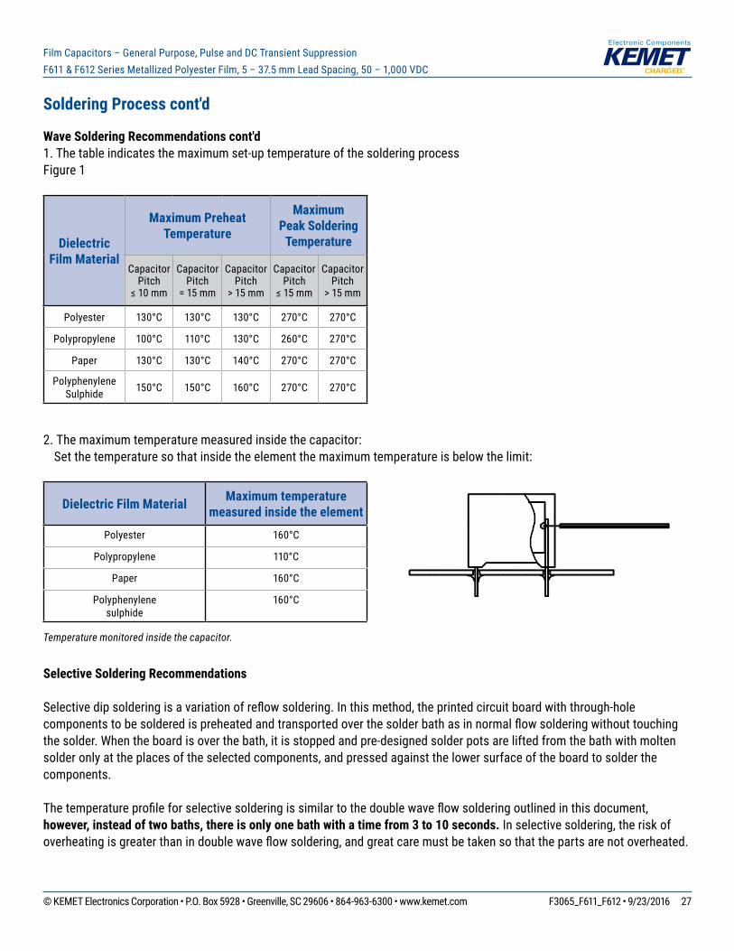
Wave Soldering Recommendations cont'd1. The table indicates the maximum set-up temperature of the soldering processFigure 1
Dielectric Film Material
Maximum Preheat Temperature
Maximum Peak Soldering
Temperature
Capacitor Pitch
≤10mm
Capacitor Pitch
= 15 mm
Capacitor Pitch
> 15 mm
Capacitor Pitch
≤15mm
Capacitor Pitch
> 15 mm
Polyester 130°C 130°C 130°C 270°C 270°C
Polypropylene 100°C 110°C 130°C 260°C 270°C
Paper 130°C 130°C 140°C 270°C 270°C
Polyphenylene Sulphide 150°C 150°C 160°C 270°C 270°C
2. The maximum temperature measured inside the capacitor: Set the temperature so that inside the element the maximum temperature is below the limit:
Dielectric Film Material Maximum temperature measured inside the element
Polyester 160°C
Polypropylene 110°C
Paper 160°C
Polyphenylene sulphide
160°C
Temperature monitored inside the capacitor.
Selective Soldering Recommendations
Selectivedipsolderingisavariationofreflowsoldering.Inthismethod,theprintedcircuitboardwiththrough-holecomponentstobesolderedispreheatedandtransportedoverthesolderbathasinnormalflowsolderingwithouttouchingthe solder. When the board is over the bath, it is stopped and pre-designed solder pots are lifted from the bath with molten solder only at the places of the selected components, and pressed against the lower surface of the board to solder the components.
Thetemperatureprofileforselectivesolderingissimilartothedoublewaveflowsolderingoutlinedinthisdocument,however, instead of two baths, there is only one bath with a time from 3 to 10 seconds. In selective soldering, the risk of overheatingisgreaterthanindoublewaveflowsoldering,andgreatcaremustbetakensothatthepartsarenotoverheated.

© KEMET Electronics Corporation • P.O. Box 5928 • Greenville, SC 29606 • 864-963-6300 • www.kemet.com F3065_F611_F612 • 9/23/2016 28
Film Capacitors – General Purpose, Pulse and DC Transient Suppression F611 & F612 Series Metallized Polyester Film, 5 – 37.5 mm Lead Spacing, 50 – 1,000 VDC
Construction
Molded Plastic Case
Leads
Metal Contact Layer
Metal Contact Layer
Margin
Single-sided Metallized Polyester Film (Second Layer)
Single-sided Metallized Polyester Film (First Layer)
Margin
Margin
Detailed Cross SectionSelf-Extinguishing
ResinMolded Plastic
Case
Wound
Winding Scheme
Single-sided Metallized
Polypropylene Film
FILM WINDING SCHEME OPTIONS
1 Section
Single-sided Metallized
Polypropylene Film
Single-sided Metallized
Polypropylene Film
Single-sided Metallized
Polypropylene Film
Single-sided Metallized Polypropylene Film
2 Sections
3 Sections 4 Sections
Single-sided Metallized
Polypropylene Film
Polypropylene Film Dielectric
1 Section
Double-sided Metallized Polyester Film
3 Sections
Double-sided Metallized Polyester
Carrier Film
Polypropylene Film Dielectric
Double-sided Metallized Polyester
Carrier Film
2 Sections
Polypropylene Film DielectricDouble-sided
Metallized Polyester Carrier
Film
Single-sided Metallized
Polypropylene Film
4 Sections
Polypropylene Film DielectricDouble-sided
Metallized Polyester Carrier
Film
Polypropylene Film Dielectric
1 Section
Polypropylene Film/Foil
2 Sections
Metal Foil Metal Foil
Single-sided Metallized
Polypropylene Film
Polypropylene Film Dielectric
Metallized Polyphenyl-ene Sulfide Film with Vacuum-Evaporated
Aluminum Electrodes
1 Section
Metallized Polyphenylene Sulfide Film (SMR)
Metallized Impregnated
Paper
1 Section
Metallized Impregnated Paper
Single-sided Metallized Polyester
Film
1 Section
Single-sided Metallized Polyester Film
Polypropylene Film Dielec-
tric
1 Section
AXIAL - Polypropylene Film/Foil
2 Sections
Metal Foil
Single-sided Metallized
Polypropylene Film
Polypropylene Film DielectricMetal Foil
Single-sided Metallized
Polypropylene Film
2 Sections
Polypropylene Film Dielectric
Double-sided Metallized
Polyester Carrier Film
Single-sided Metallized
Polypropylene Film
1 Section
AXIAL - Single-sided Metallized Polypropylene Film
Single-sided Metallized Polyester
Film
1 Section
AXIAL - Single-sided Metallized Polyester Film
AXIAL - Double-sided Metallized Polyester Film
© KEMET Electronics Corporation • P.O. Box 5928 • Greenville, SC 29606 • 864-963-6300 • www.kemet.com F3065_F611_F612 • 9/23/2016 29
Film Capacitors – General Purpose, Pulse and DC Transient Suppression F611 & F612 Series Metallized Polyester Film, 5 – 37.5 mm Lead Spacing, 50 – 1,000 VDC
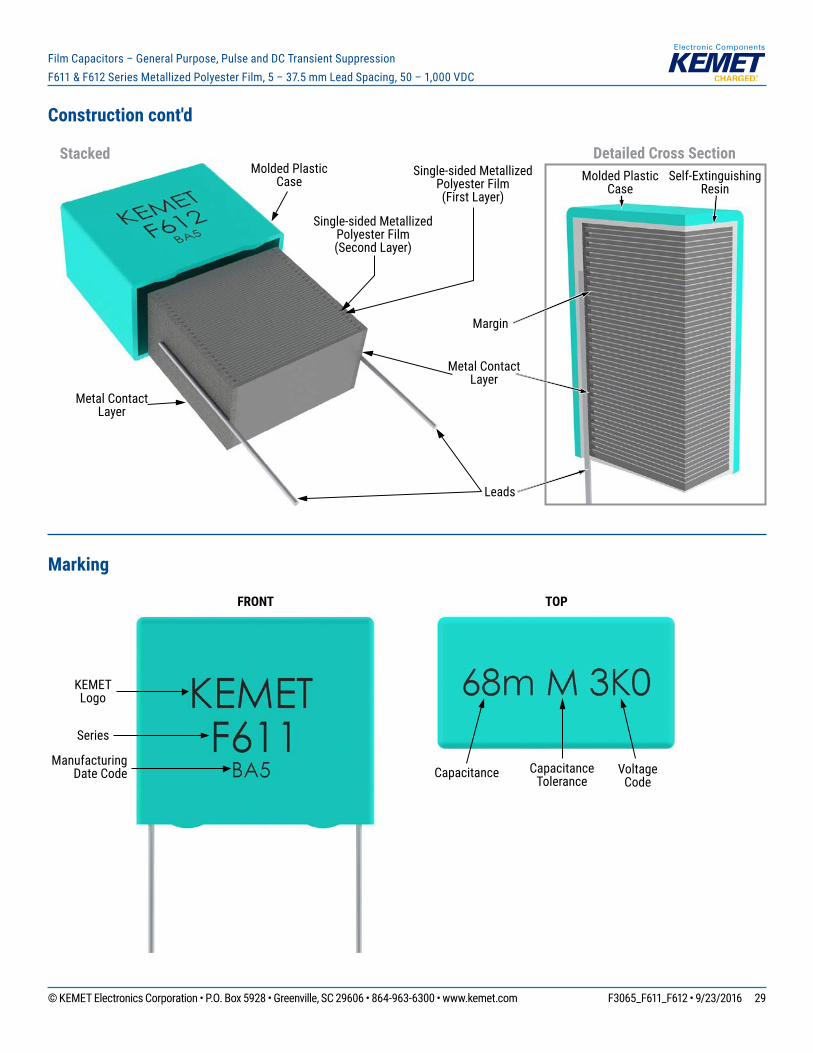
Construction cont'd
Molded Plastic Case
Leads
Metal Contact Layer
Metal Contact Layer
Margin
Single-sided Metallized Polyester Film (Second Layer)
Single-sided Metallized Polyester Film (First Layer)
Detailed Cross SectionSelf-Extinguishing
ResinMolded Plastic
Case
Stacked
Marking
TOPFRONT
Capacitance Capacitance Tolerance
Series
Voltage Code
KEMET Logo
Manufacturing Date Code

© KEMET Electronics Corporation • P.O. Box 5928 • Greenville, SC 29606 • 864-963-6300 • www.kemet.com F3065_F611_F612 • 9/23/2016 30
Film Capacitors – General Purpose, Pulse and DC Transient Suppression F611 & F612 Series Metallized Polyester Film, 5 – 37.5 mm Lead Spacing, 50 – 1,000 VDC
Packaging Quantities
Size Code Lead Spacing
Thickness (mm)
Height(mm)
Length (mm)
BulkShort Leads
BulkLong Leads
Standard Reel
ø 355 mm
Large Reelø 500 mm Ammo Pizza
JF
5
2.5 6.5 7.2 3000 4000 2500 3500JG 3.5 7.5 7.2 2000 3000 1800 2500JM 4.5 9.5 7.2 1500 2000 1400 1900JQ 5.0 10.0 7.2 1000 1500 1200 1700JT 6 11 7.2 2000 1000 1000 1400JU 7.2 13 7.2 1500 750 800 1150
KE
7.5
2.5 6 10 2000 3000 2500 3500KF 3 8 10 1500 1750 2100 2800KG 4 8 10 2000 1500 1500 2100KJ 5 10.5 10 1500 1000 1200 1600KM 6 12 10.5 1000 800 1000 1350KH 4 9 10 2000 1500 1500 2100
AN
10
3.5 9 13 2200 3200 850 1700 1150AG 4 9 13 2000 2200 750 1500 1000AK 5 11 13 1300 2000 600 1250 800AP 6 12 13 1000 1800 500 1000 680AO 7 17 13 600 900 450 900 580AL 9.5 7.5 13 1100 2000 300 600 430AE 4 8 13 2000 2200 750 1500 1000
BB
15
4 10 18 1300 1500 750 1500 1000 1411BC 5 11 18 1000 1250 600 1250 800 1139BE 5.5 12.5 18 800 1100 550 1100 750 1020BG 6 12 18 1750 1000 500 1000 680 935BK 7.5 13.5 18 1000 800 350 800 500 748BI 6 17.5 18 1000 800 500 1000 680 935BP 8.5 14.5 18 1000 650 300 700 440 663BT 9 12.5 18 1000 700 270 650 410 629BO 7.5 18.5 18 900 600 350 800 500 748BS 10 16 18 750 550 300 600 380 561BR 13 12 18 750 520 200 480 280 425BY 11 19 18 450 400 250 500 340 510BA 8.5 12.5 18 1000 650 300 700 440 663BZ 12 20 18 350 300 220 450 330 459

© KEMET Electronics Corporation • P.O. Box 5928 • Greenville, SC 29606 • 864-963-6300 • www.kemet.com F3065_F611_F612 • 9/23/2016 31
Film Capacitors – General Purpose, Pulse and DC Transient Suppression F611 & F612 Series Metallized Polyester Film, 5 – 37.5 mm Lead Spacing, 50 – 1,000 VDC
Packaging Quantities cont'd
Size Code Lead Spacing
Thickness (mm)
Height(mm)
Length (mm)
BulkShort Leads
BulkLong Leads
Standard Reel
ø 355 mm
Large Reelø 500 mm Ammo Pizza
DB
22.5
6 14.5 26 1638 702 300 700 464 660DI 7 16 26 1188 594 250 550 380 564DH 8.0 16.0 26 1026 513 240 500 330 492DJ 8.5 17 26 972 486 250 450 280 468DM 9 18.5 26 918 459 200 400 300 444DO 10 18.5 26 810 405 160 350 235 396DP 11 20 26 756 378 190 350 217 360DU 13 22 26 540 324 150 300 200 300DY 15.5 24.5 26 450 270 120 250 170 252
FB
27.5
9.0 17.0 31.5 816 408 370FC 11.0 20.0 31.5 672 336 300FI 13.0 25.0 31.5 480 288 250FN 14.0 28.0 31.5 352 176 230FO 17.0 40.0 31.5 216 144 190FR 17.5 28.0 31.5 256 128 190FS 19.0 29.0 31.5 256 128 170FY 22.0 37.0 31.5 168 112 150FH 21.0 12.5 31.5 392 168 150FQ 27.5 16.0 31.5 280 120 120FT 31.0 19.0 31.5 240 120 100
RB
37.5
11.0 22.0 41.0 420 252 210RF 13.0 24.0 41.0 360 216 175RH 15.0 26.0 41.0 300 180 154RC 16.0 28.5 41.0 216 108 140RD 19.0 32.0 41.0 192 96 119RP 21.0 38.0 41.0 126 84 105RO 24.0 44.0 41.0 108 72 91RU 30.0 45.0 41.0 90 60 77RV 24.0 15.0 41.0 252 108 91RW 24.0 19.0 41.0 216 108 91

© KEMET Electronics Corporation • P.O. Box 5928 • Greenville, SC 29606 • 864-963-6300 • www.kemet.com F3065_F611_F612 • 9/23/2016 32
Film Capacitors – General Purpose, Pulse and DC Transient Suppression F611 & F612 Series Metallized Polyester Film, 5 – 37.5 mm Lead Spacing, 50 – 1,000 VDC
Lead Taping & Packaging (IEC 60286–2)
Taping Specifi cation
Dimensions in mm Standard IEC 60286–2Lead spacing +6/-0.1 F 5 7.5 10 15 22.5 27.5 F
Carrier tape width +1/-0.5 W 18 18 18 18 18 18 18+1/-0.5
Hold-down tape width Minimum W0 6 6 9 10 10 10
Position of sprocket hole +/-0.5 W1 9 9 9 9 9 9 9+0.75/-0.5
Distance between tapes Maximum W2 3 3 3 3 3 3 3
Sprocket hole diameter +/-0.2 D0 4 4 4 4 4 4 4
Feed hole lead spacing +/-0.2(1) P0(3) 12.7 12.7 12.7 12.7 12.7 12.7 12.7
Distance lead – feed hole +/-0.7 P1 3.85 3.75 7.7 5.2 7.8 5.3 P1
Deviation tape – plane Maximum Δp 1.3 1.3 1.3 1.3 1.3 1.3 1.3
Lateral deviation +/-2 Δh 2 2 2 2 2 2 2
Total thickness +/-0.2 t 0.7 0.7 0.7 0.7 0.9MAX 0.9MAX 0.9MAX
Sprocket hole/cap body +/-0.5 H0(2) 18.5+/-0.5 18.5+/-0.5 18.5+/-0.5 18.5+/-0.5 18.5+/-0.5 18.5+/-0.5 18+2/-0
(1) Maximum cumulative feed hole error, 1 mm per 20 parts.(2) 16.5 mm available on request.(3) 15 mm available on request (F ≥ 10 mm).
Lead Spacing 5 mm Lead Spacing 7.5 mm
Lead Spacing 10 – 15 mm Lead Spacing 22.5 – 27.5 mm
0 0
0 0
© KEMET Electronics Corporation • P.O. Box 5928 • Greenville, SC 29606 • 864-963-6300 • www.kemet.com F3065_F611_F612 • 9/23/2016 33
Film Capacitors – General Purpose, Pulse and DC Transient Suppression F611 & F612 Series Metallized Polyester Film, 5 – 37.5 mm Lead Spacing, 50 – 1,000 VDC
H
TW
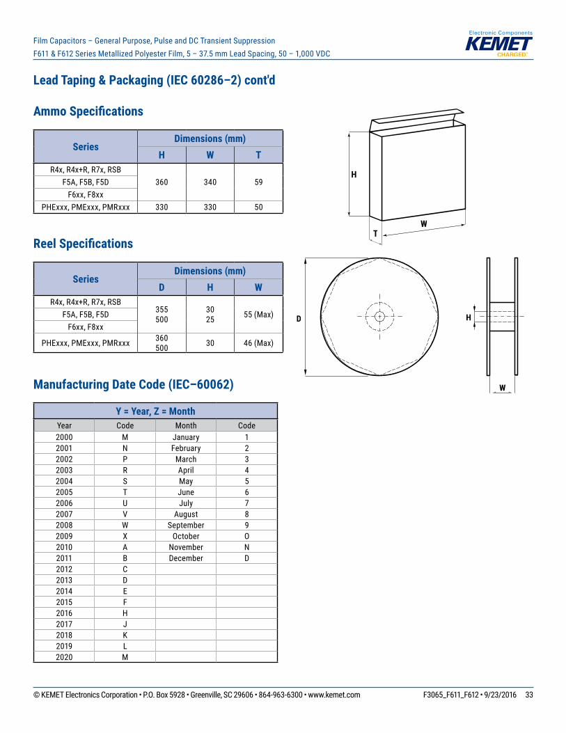
Lead Taping & Packaging (IEC 60286–2) cont'd
Ammo Specifi cations
SeriesDimensions (mm)
H W TR4x,R4x+R,R7x,RSB
360 340 59F5A, F5B, F5DF6xx, F8xx
PHExxx, PMExxx, PMRxxx 330 330 50
Reel Specifi cations
SeriesDimensions (mm)
D H WR4x,R4x+R,R7x,RSB
355500
3025 55 (Max)F5A, F5B, F5D
F6xx, F8xx
PHExxx, PMExxx, PMRxxx 360500 30 46 (Max)
Manufacturing Date Code (IEC–60062)
Y = Year, Z = MonthYear Code Month Code2000 M January 12001 N February 22002 P March 32003 R April 42004 S May 52005 T June 62006 U July 72007 V August 82008 W September 92009 X October O2010 A November N2011 B December D2012 C2013 D2014 E2015 F2016 H2017 J2018 K2019 L2020 M
D
W
H

© KEMET Electronics Corporation • P.O. Box 5928 • Greenville, SC 29606 • 864-963-6300 • www.kemet.com F3065_F611_F612 • 9/23/2016 34
Film Capacitors – General Purpose, Pulse and DC Transient Suppression F611 & F612 Series Metallized Polyester Film, 5 – 37.5 mm Lead Spacing, 50 – 1,000 VDC
KEMET Electronic Corporation Sales Offi ces
Foracompletelistofourglobalsalesoffices,pleasevisitwww.kemet.com/sales.
DisclaimerAllproductspecifications,statements,informationanddata(collectively,the“Information”)inthisdatasheetaresubjecttochange.Thecustomerisresponsibleforchecking and verifying the extent to which the Information contained in this publication is applicable to an order at the time the order is placed.
All Information given herein is believed to be accurate and reliable, but it is presented without guarantee, warranty, or responsibility of any kind, expressed or implied.
StatementsofsuitabilityforcertainapplicationsarebasedonKEMETElectronicsCorporation’s(“KEMET”)knowledgeoftypicaloperatingconditionsforsuchapplications,butarenotintendedtoconstitute–andKEMETspecificallydisclaims–anywarrantyconcerningsuitabilityforaspecificcustomerapplicationoruse.The Information is intended for use only by customers who have the requisite experience and capability to determine the correct products for their application. Any technical advice inferred from this Information or otherwise provided by KEMET with reference to the use of KEMET’s products is given gratis, and KEMET assumes no obligation or liability for the advice given or results obtained.
Although KEMET designs and manufactures its products to the most stringent quality and safety standards, given the current state of the art, isolated component failures may still occur. Accordingly, customer applications which require a high degree of reliability or safety should employ suitable designs or other safeguards (suchasinstallationofprotectivecircuitryorredundancies)inordertoensurethatthefailureofanelectricalcomponentdoesnotresultinariskofpersonalinjuryorproperty damage.
Although all product–related warnings, cautions and notes must be observed, the customer should not assume that all safety measures are indicted or that other measures may not be required.
KEMET is a registered trademark of KEMET Electronics Corporation.
![Untitled-1 [] · chamber Intake Port Volume Volume Eliminators ... 1487 Street Eliminator Heads- 94 Bore (42 x 37.5) ... 1541 CNC S.E. Heads - 94 bore (42 x 37.5) . 1543](https://img.dokumen.tips/doc/110x75/5b16763c7f8b9a596d8c2287/untitled-1-chamber-intake-port-volume-volume-eliminators-1487-street.jpg)