Embed Size (px)
Citation preview

Roy
al H
asko
ning
DH
V,
Mar
ktha
l-R
otte
rdam
, The
Net
herla
nds,
© P
hoto
sou
rce:
Oss
ip v
an D
uive
nbod
e
Author: Iveta GeorgievaDate: 2 December 2016
General method according to EN 1993-1-1, §6.3.4
Formulation. Methodology and applications in the context of CAE

What is the General Method?
When is it used?
Formulation
Some examples
Limitations
Conclusion
Content of presentation

Evaluation of member/2D frame stability: in-plane & out-of-plane
Simple formulation
Difficulty: in deriving the 2 essential parameters (αult,k & αcr,op)
Requires the use of FE software
May apply to:
complex structural components
structural components with complex restraint conditions & load
What is the General Method?

Why: resistance for lateral (FB) and lateral-torsional buckling (LTB)
When: where §6.3.1 -- §6.3.3 do not apply
For:
single members (built-up or not, uniform or not, with irregular support conditions or not)
plane frames or sub-frames composed of such members
Load: compression and/or (mono-axial) in-plane bending and shear
To watch out: no plastic hinge rotates!
The National Annex may specify the field and limits of application of this method
Applications of the General Method

NBN EN 1993-1-1 ANB:
Accepted as a general procedureOnly when EC3-1-1, §6.3.1 -- §6.3.3 CANNOT be applied
NF EN 1993-1-1 NA:
Requires that in-plane stability be determined from elastic analysis of the whole structure
DIN EN 1993-1-1 NA:
Limits to I-sections onlyIn-plane stability is limited by formation of first plastic hinge
BS EN 1993-1-1 NA:
Nominally straight components
Applications of the General Method
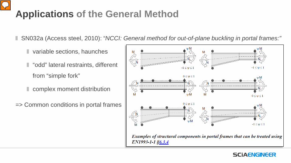
SN032a (Access steel, 2010): “NCCI: General method for out-of-plane buckling in portal frames:”
variable sections, haunches
“odd” lateral restraints, different
from “simple fork”
complex moment distribution
=> Common conditions in portal frames
Applications of the General Method

Design against lateral or lateral-torsional buckling:
Imperfections:
Global imperfections of the frame
Local (member) imperfections
Deformations:
Second-order deformation in the frame (nodal displacements)
Local (member) second-order deformation
For uniform members: contained in EN 1993-1-1, Chapters §6.3.1 to §6.3.3
Intermezzo: Stability design of steel frames

Interaction
Analytical methods according to EN 1993-1-1, 6.2 & 6.3.1 to 6.3.3
Intermezzo: Stability design of steel frames
Compression Bending in-plane
Interaction
Stability check…Section check… Stability check…Section check…
(Flexural buckling)
(Lateral-torsional buckling)
Annex A/Annex B

Section checks & general method according to EN 1993-1-1, 6.2 & 6.3.4
Intermezzo: Stability design of steel frames
Compression Bending in-plane
Interaction
Stability check…Section check… Stability check…Section check…
General method

Formulation of the General MethodAnalysis of the whole structure with global imperfections
In-plane stability
(FB around y-y)
Out-of-plane stability
(FB around z-z, LTB)
G(M)NIAFully restrained
out-of-plane
LBAAccount for
warping
αult,k αcr,op
�χ𝑜𝑜𝑜𝑜α𝑢𝑢𝑢𝑢𝑢𝑢,𝑘𝑘γ𝑀𝑀𝑀 ≥ 1
Selected member/2D frame
Stability verification based on General Method
�λ𝑜𝑜𝑜𝑜 = �α𝑢𝑢𝑢𝑢𝑢𝑢,𝑘𝑘α𝑐𝑐𝑐𝑐,𝑜𝑜𝑜𝑜
𝜒𝜒𝑜𝑜𝑜𝑜 = min 𝜒𝜒,𝜒𝜒𝐿𝐿𝐿𝐿
Buckling curves for critical section

χop=min(χ, χLT)
Formulation of the General Method
In-plane stability
(FB around y-y)
Out-of-plane stability
(FB around z-z, LTB)
G(M)NIAFully restrained
out-of-plane
LBAAccount for
warping
αult,k αcr,op
�χ𝑜𝑜𝑜𝑜α𝑢𝑢𝑢𝑢𝑢𝑢,𝑘𝑘γ𝑀𝑀𝑀 ≥ 1
Buckling curves for critical section
Selected member/2D frame
Stability verification based on General Method
�λ𝑜𝑜𝑜𝑜 = �α𝑢𝑢𝑢𝑢𝑢𝑢,𝑘𝑘α𝑐𝑐𝑐𝑐,𝑜𝑜𝑜𝑜
Option 1
global analysis model
Option 2
Load: internal forces from global model & local loadBCs: hinges at extremities
Analysis of the whole structure with global imperfections

Formulation of the General Method
In-plane stability
(FB around y-y)
Out-of-plane stability
(FB around z-z, LTB)
G(M)NIAFully restrained
out-of-plane
LBAAccount for
warping
αult,k αcr,op
�χ𝑜𝑜𝑜𝑜α𝑢𝑢𝑢𝑢𝑢𝑢,𝑘𝑘γ𝑀𝑀𝑀 ≥ 1
Selected member/2D frame
Stability verification based on General Method
�λ𝑜𝑜𝑜𝑜 = �α𝑢𝑢𝑢𝑢𝑢𝑢,𝑘𝑘α𝑐𝑐𝑐𝑐,𝑜𝑜𝑜𝑜
𝜒𝜒𝑜𝑜𝑜𝑜 = min 𝜒𝜒,𝜒𝜒𝐿𝐿𝐿𝐿
Buckling curves for critical section
Analysis of the whole structure with global imperfections

Analysis of the whole structure with global imperfections
Formulation of the General Method
In-plane stability
(FB around y-y)
Out-of-plane stability
(FB around z-z, LTB)
G(M)NIAFully restrained
out-of-plane
LBAAccount for
warping
αcr,op
λ𝑜𝑜𝑜𝑜 = �α𝑢𝑢𝑢𝑢𝑢𝑢,𝑘𝑘α𝑐𝑐𝑐𝑐,𝑜𝑜𝑜𝑜
χop=min(χ, χLT) �χ𝑜𝑜𝑜𝑜α𝑢𝑢𝑢𝑢𝑢𝑢,𝑘𝑘γ𝑀𝑀𝑀 ≥ 1
Buckling curves for critical section
Selected member/2D frame
Stability verification based on General Method
How much we have to increase the design load in order to:
Reach the characteristic resistance of the most critical cross-section,…… considering the member/frame in-plane behaviour: in-plane geometrical deformation and imperfections……without taking lateral or lateral torsional buckling into account
αult,k

Formulation of the General Method & Example
2D frame
• members of variable height
• “design load:” 10 kN/m
• slender sections

Formulation of the General Method & Example
In-plane stability
(FB around y-y)
G(M)NIAFully restrained
out-of-plane
αult,k
Model: 2nd order analysis of the frame taking into account all in-plane effects:
3 DoF beam elements
~10 sections per member
per section: (effective) cross-section properties and class
global and member imperfections

Formulation of the General Method & Example
In-plane stability
(FB around y-y)
G(M)NIAFully restrained
out-of-plane
αult,k
Model: 2nd order analysis of the frame taking into account all in-plane effects:
Run analysis
Make sure no plastic hinge rotates!
Derive unity Cross-Section Check value per section
Maximal unity check == critical section
𝜶𝜶𝒖𝒖𝒖𝒖𝒖𝒖,𝒌𝒌 = 𝟐𝟐.𝟏𝟏𝟏𝟏 ≥ 𝟏𝟏

Formulation of the General Method
In-plane stability
(FB around y-y)
Out-of-plane stability
(FB around z-z, LTB)
G(M)NIAFully restrained
out-of-plane
LBAAccount for
warping
αult,k αcr,op
λ𝑜𝑜𝑜𝑜 = �α𝑢𝑢𝑢𝑢𝑢𝑢,𝑘𝑘α𝑐𝑐𝑐𝑐,𝑜𝑜𝑜𝑜
�χ𝑜𝑜𝑜𝑜α𝑢𝑢𝑢𝑢𝑢𝑢,𝑘𝑘γ𝑀𝑀𝑀 ≥ 1
Selected member/2D frame
Stability verification based on General Method
𝜒𝜒𝑜𝑜𝑜𝑜 = min 𝜒𝜒,𝜒𝜒𝐿𝐿𝐿𝐿
Buckling curves for critical section
Analysis of the whole structure with global imperfections

Analysis of the whole structure with global imperfections
𝜒𝜒𝑜𝑜𝑜𝑜 = min 𝜒𝜒,𝜒𝜒𝐿𝐿𝐿𝐿
Buckling curves for critical section
Formulation of the General Method
In-plane stability
(FB around y-y)
Out-of-plane stability
(FB around z-z, LTB)
G(M)NIAFully restrained
out-of-plane
LBAAccount for
warping
λ𝑜𝑜𝑜𝑜 = �α𝑢𝑢𝑢𝑢𝑢𝑢,𝑘𝑘α𝑐𝑐𝑐𝑐,𝑜𝑜𝑜𝑜
�χ𝑜𝑜𝑜𝑜α𝑢𝑢𝑢𝑢𝑢𝑢,𝑘𝑘γ𝑀𝑀𝑀 ≥ 1
Selected member/2D frame
Stability verification based on General Method
αult,kHow much we have to increase the design load in order to:
Reach the elastic critical resistance of the structural component,…… with regards to lateral or lateral-torsional buckling…… without taking in-plane flexural buckling into account
αcr,op

Formulation of the General Method
Out-of-plane stability
(FB around z-z, LTB)
LBAAccount for
warping
Linear stability analysis of the frame ignoring all in-plane effects:
Elastic analysis
No imperfections needed
Warping deformation needed:
Shell elements
7DoF beam elements
The first eigen mode representing LB or LTB is the critical
𝛼𝛼𝑐𝑐𝑐𝑐,𝑜𝑜𝑜𝑜 : the load factor for this critical mode
𝛼𝛼𝑐𝑐𝑐𝑐,𝑜𝑜𝑜𝑜 ≥ 1
αcr,op

Linear stability analysis of the frame ignoring all in-plane effects:
Formulation of the General Method & Example
Out-of-plane stability
(FB around z-z, LTB)
LBAAccount for
warping
αcr,op
Mesh size 5 cm
Fork support
Fork support
Lateral restraint
Shell elements

Linear stability analysis of the frame ignoring all in-plane effects:
Formulation of the General Method & Example
Out-of-plane stability
(FB around z-z, LTB)
LBAAccount for
warping
αcr,op
From above
Critical mode shape: No 1Load factor: 2.12
𝜶𝜶𝒄𝒄𝒄𝒄,𝒐𝒐𝒐𝒐 = 𝟐𝟐.𝟏𝟏𝟐𝟐 ≥ 𝟏𝟏

Formulation of the General Method
In-plane stability
(FB around y-y)
Out-of-plane stability
(FB around z-z, LTB)
G(M)NIAFully restrained
out-of-plane
LBAAccount for
warping
αult,k αcr,op
�χ𝑜𝑜𝑜𝑜α𝑢𝑢𝑢𝑢𝑢𝑢,𝑘𝑘γ𝑀𝑀𝑀 ≥ 1
Selected member/2D frame
Stability verification based on General Method
�λ𝑜𝑜𝑜𝑜 = �α𝑢𝑢𝑢𝑢𝑢𝑢,𝑘𝑘α𝑐𝑐𝑐𝑐,𝑜𝑜𝑜𝑜
𝜒𝜒𝑜𝑜𝑜𝑜 = min 𝜒𝜒,𝜒𝜒𝐿𝐿𝐿𝐿
Buckling curves for critical section
Analysis of the whole structure with global imperfections

Analysis of the whole structure with global imperfections
Formulation of the General Method
In-plane stability
(FB around y-y)
Out-of-plane stability
(FB around z-z, LTB)
G(M)NIAFully restrained
out-of-plane
LBAAccount for
warping
�χ𝑜𝑜𝑜𝑜α𝑢𝑢𝑢𝑢𝑢𝑢,𝑘𝑘γ𝑀𝑀𝑀 ≥ 1
Selected member/2D frame
Stability verification based on General Method
αult,k αcr,op
�λ𝑜𝑜𝑜𝑜 = �α𝑢𝑢𝑢𝑢𝑢𝑢,𝑘𝑘α𝑐𝑐𝑐𝑐,𝑜𝑜𝑜𝑜
Relative slenderness of member/(sub)frame
Reduction factor of the resistance; takes into account all out-of-plane effects
𝜒𝜒𝑜𝑜𝑜𝑜 = min 𝜒𝜒,𝜒𝜒𝐿𝐿𝐿𝐿
Buckling curves for critical section

Formulation of the General Method
�λ𝑜𝑜𝑜𝑜 = �α𝑢𝑢𝑢𝑢𝑢𝑢,𝑘𝑘α𝑐𝑐𝑐𝑐,𝑜𝑜𝑜𝑜
Critical section from calculation of α𝑢𝑢𝑢𝑢𝑢𝑢,𝑘𝑘
EN 1993-1-1, §6.3.1
𝜒𝜒 =1
𝛷𝛷 + 𝛷𝛷2 − �λ2
𝛷𝛷 = 0.5 1 + 𝛼𝛼 �λ− 0.2 + �λ2
EN 1993-1-1, §6.3.2
𝜒𝜒𝐿𝐿𝐿𝐿 =1
𝛷𝛷𝐿𝐿𝐿𝐿 + 𝛷𝛷𝐿𝐿𝐿𝐿2 − �λ𝐿𝐿𝐿𝐿2
𝛷𝛷𝐿𝐿𝐿𝐿 = 0.5 1 + 𝛼𝛼𝐿𝐿𝐿𝐿 �λ𝐿𝐿𝐿𝐿 − 0.2 + �λ𝐿𝐿𝐿𝐿2
𝜒𝜒 = 1𝜒𝜒𝐿𝐿𝐿𝐿 = 1
χop=min(χ, χLT)
�λ𝑜𝑜𝑜𝑜 > �λ𝐿𝐿𝐿𝐿,0�λ𝑜𝑜𝑜𝑜 > 0.2

𝜶𝜶𝒖𝒖𝒖𝒖𝒖𝒖,𝒌𝒌 = 𝟐𝟐.𝟏𝟏𝟏𝟏 ≥ 𝟏𝟏
𝜶𝜶𝒄𝒄𝒄𝒄,𝒐𝒐𝒐𝒐 = 𝟐𝟐.𝟏𝟏𝟐𝟐 ≥ 𝟏𝟏
�λ𝑜𝑜𝑜𝑜 = �α𝑢𝑢𝑢𝑢𝑢𝑢,𝑘𝑘 α𝑐𝑐𝑐𝑐,𝑜𝑜𝑜𝑜 = �2.162.12 = 1.01
At critical section: FB curve b, 𝜶𝜶 = 0.34
𝛷𝛷 = 0.5 1 + 𝜶𝜶 �λ − 0.2 + �λ2 = 1.15
𝜒𝜒
At critical section: LTB curve d, 𝜶𝜶𝑳𝑳𝑳𝑳 = 0.76
𝛷𝛷𝐿𝐿𝐿𝐿 = 0.5 1 + 𝜶𝜶𝑳𝑳𝑳𝑳 �λ𝐿𝐿𝐿𝐿 − 0.2 + �λ𝐿𝐿𝐿𝐿2 = 1.32
𝜒𝜒𝐿𝐿𝐿𝐿 =
𝜒𝜒𝑜𝑜𝑜𝑜 = min 𝜒𝜒,𝜒𝜒𝐿𝐿𝐿𝐿 = 𝟎𝟎.𝟒𝟒𝟏𝟏
Formulation of the General Method & Example
=1
𝛷𝛷 + 𝛷𝛷2 − �λ2= 𝟎𝟎.𝟓𝟓𝟓𝟓
1
𝛷𝛷𝐿𝐿𝐿𝐿 + 𝛷𝛷𝐿𝐿𝐿𝐿2 − �λ𝐿𝐿𝐿𝐿2
= 𝟎𝟎.𝟒𝟒𝟏𝟏

Formulation of the General Method
In-plane stability
(FB around y-y)
Out-of-plane stability
(FB around z-z, LTB)
G(M)NIAFully restrained
out-of-plane
LBAAccount for
warping
αult,k αcr,op
λ𝑜𝑜𝑜𝑜 = �α𝑢𝑢𝑢𝑢𝑢𝑢,𝑘𝑘α𝑐𝑐𝑐𝑐,𝑜𝑜𝑜𝑜
𝜒𝜒𝑜𝑜𝑜𝑜 = min 𝜒𝜒,𝜒𝜒𝐿𝐿𝐿𝐿 �χ𝑜𝑜𝑜𝑜α𝑢𝑢𝑢𝑢𝑢𝑢,𝑘𝑘γ𝑀𝑀𝑀 ≥ 1
Buckling curves for critical section
Selected member/2D frame
Stability verification based on General Method
Analysis of the whole structure with global imperfections

Analysis of the whole structure with global imperfections
Buckling curves for critical section
Formulation of the General Method
In-plane stability
(FB around y-y)
Out-of-plane stability
(FB around z-z, LTB)
G(M)NIAFully restrained
out-of-plane
LBAAccount for
warping
αcr,op
Selected member/2D frame
�λ𝑜𝑜𝑜𝑜 = �α𝑢𝑢𝑢𝑢𝑢𝑢,𝑘𝑘α𝑐𝑐𝑐𝑐,𝑜𝑜𝑜𝑜
�χ𝑜𝑜𝑜𝑜α𝑢𝑢𝑢𝑢𝑢𝑢,𝑘𝑘γ𝑀𝑀𝑀 ≥ 1Stability verification
based on General Method
𝜶𝜶𝒖𝒖𝒖𝒖𝒖𝒖,𝒌𝒌 = 2.16
𝝌𝝌𝒐𝒐𝒐𝒐 = 0.46 �0.46 × 2.161.0 = 0.994 ≈ 1

Example 2
From: “Background document to EN 1993-1-1,”
G. Sedlacek, J. Naumes, 2009
A support frame from the Schwebebahn in Wuppertal
Variable cross-section
Fork supports modelled at column feet
Beam laterally supported eccentrically in 2 points
Asymmetric loading
Non-uniform distribution of N and My

Example 2
From: “Background document to EN 1993-1-1,”
G. Sedlacek, J. Naumes, 2009


ECCS TC8 Stability (2006): “Field and limits of application of the General Method:”
Linear members and truss and frame structures built-up out of linear members,
where the lateral (torsional) buckling is related to a straight member behaviour. Sufficient
lateral supports should be present such that the behaviour with respect to overall buckling
between these lateral supports can be regarded as a straight member behaviour.
For structures/components out of the scope of the general method, a rigorous method like 3D
GMNIA should be applied
The General Method is always on the safe side when compared to a full 3D GMNIA
Limitations of the General Method

The general method is used for stability verifications for:
standard or complex structural components
with complex loading or boundary conditions (or not)
loaded in compression and/or in-plane bending
The method takes into account:
in-plane imperfections & loss of in-plane stability by GMNIA of the structural component
out-of-plane loss of stability by LBA of the component (eventually, by the reduction factor χ𝑜𝑜𝑜𝑜)
out-of-plane imperfections by adopting the appropriate buckling curve in the derivation of χ𝑜𝑜𝑜𝑜
Conclusion

[1] G. Sedlacek, J. Naumes, CEN / TC250 / SC3 / N1639E - rev2, Background Document to EN 1993-1-1, Aachen, 2009.
[2] A. Bureau, Résistance au flambement et au déversement d’un Poteau a inertie variable selon l‘EN1993-1-1, Revue Construction Métallique, issue 3, 2007
[3] L. Zdravkov, Using of general method of standard EN 1993-1-1 to design of self-supporting cone roofs,4th International Conference of Advanced Construction, Kaunas, Lithuania, 2014.
[4] SN032a-EN-EU, NCCI: General method for out-of-plane buckling in portal frames, Access Steel, 2010.
[5] B. Snijder, R. Greiner, J.-P. Jaspart, TC8-2006-015, Field and limits of application of the GeneralMethod, ECCS TC8 Stability, 2006.
[6] R. Greiner, Stabilitätsnachweis von Stabwerken nach dem Eurocode – neue Möglichkeiten, Institut fürStahlbau und Flächentragwerke, Technische Universität Graz, 2005
[7] T. Van Leemput, M. Van Mieghem, Algemene methode voor knikken en kippen van constructieveonderdelen, Master Thesis, Lessius Mechelen, 2012
References

General method in context
Internal forces from… Modelled imperfections EN 1993-based checks required
1st order analysis none §6.2 & in-plane FB Lb ≠ Lout-of-plane FB /LTB (§6.3)
2D (in-plane) 2nd order analysis In-plane global inclination §6.2 & in-plane FB Lb = L
out-of-plane FB /LTB (§6.3)
2D (in-plane) 2nd order analysis
In-plane (1) global inclination & (2) member imperfections
§6.2 & out-of-plane FB /LTB (§6.3)
3D 2nd order analysis, warping included
Global inclinationMember imperfections Section checks only (§6.2)
(General method)1st order for whole structure
2nd order for component/frame
In-plane (1) global inclination & (2) member imperfections
§6.2 & �χ𝑜𝑜𝑜𝑜α𝑢𝑢𝑢𝑢𝑢𝑢, 𝑘𝑘 γ𝑀𝑀𝑀 ≥ 1

More information on www.scia.net
Thank you for your attention