Embed Size (px)
Citation preview
Yokogawa Corporation of America2 Dart Road Newnan, Georgia U.S.A. 30265Tel: 1 8008886400 Fax: 17702540928
GS SLC21A0-02E-A©Copyright 20042nd Edition 1/04
GeneralSpecificationsGS SLC21A0-02E-A
Diaphragm Measurement SystemsFor Use With DPharp Family of Pressure Transmitters
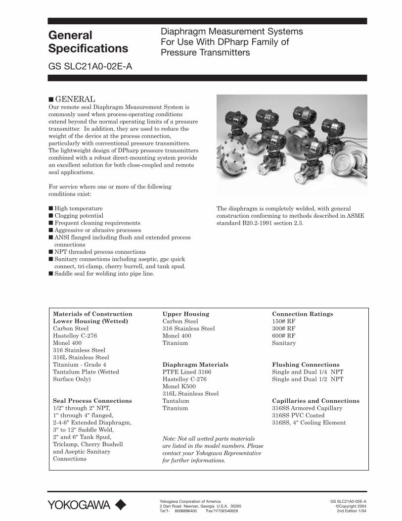
■ GENERALOur remote seal Diaphragm Measurement System iscommonly used when process-operating conditionsextend beyond the normal operating limits of a pressuretransmitter. In addition, they are used to reduce theweight of the device at the process connection,particularly with conventional pressure transmitters.The lightweight design of DPharp pressure transmitterscombined with a robust direct-mounting system providean excellent solution for both close-coupled and remoteseal applications.
For service where one or more of the followingconditions exist:
■ High temperature ■ Clogging potential■ Frequent cleaning requirements■ Aggressive or abrasive processes■ ANSI flanged including flush and extended process
connections■ NPT threaded process connections■ Sanitary connections including aseptic, gpc quick
connect, tri-clamp, cherry burrell, and tank spud.■ Saddle seal for welding into pipe line.
The diaphragm is completely welded, with generalconstruction conforming to methods described in ASMEstandard B20.2-1991 section 2.3.
Materials of Construction Lower Housing (Wetted)Carbon SteelHastelloy C-276Monel 400316 Stainless Steel316L Stainless SteelTitanium - Grade 4Tantalum Plate (Wetted Surface Only)
Seal Process Connections1/2" through 2" NPT,1" through 4" flanged,2-4-6" Extended Diaphragm,3" to 12" Saddle Weld,2" and 6" Tank Spud,Triclamp, Cherry Bushelland Aseptic SanitaryConnections
Upper HousingCarbon Steel316 Stainless SteelMonel 400Titanium
Diaphragm MaterialsPTFE Lined 3166Hastelloy C-276Monel K500316L Stainless SteelTantalumTitanium
Connection Ratings150# RF300# RF600# RFSanitary
Flushing ConnectionsSingle and Dual 1/4Ó NPTSingle and Dual 1/2Ó NPT
Capillaries and Connections316SS Armored Capillary316SS PVC Coated316SS, 4" Cooling Element
Note: Not all wetted parts materialsare listed in the model numbers. Pleasecontact your Yokogawa Representativefor further informations.
■ INTRODUCTION
The direct-mount seal (DMS) system provides a close-coupled connection to DPharp digital pressuretransmitters meeting process connection requirementsin food and beverage, biotech, pharmaceutical, chemical,and many other industries. When used with DPharpÕsunique Òauto-levelÓ software feature, DMS transmittersoffer a lower cost of ownership than our competitors.
The DMS mounting system is designed for directmounting to any DPharp pressure capsule body, thusmaintaining standard sealing characteristics whileproviding superior structural integrity. The processconnection itself is directly welded to the DMS flange,thereby eliminating potential leak paths common tothreaded connections utilized on conventionaltransmitters. Other DMS expanded capabilities includea wide variety of exotic alloys and custom flanged orthreaded process connections.
■ BENEFITS
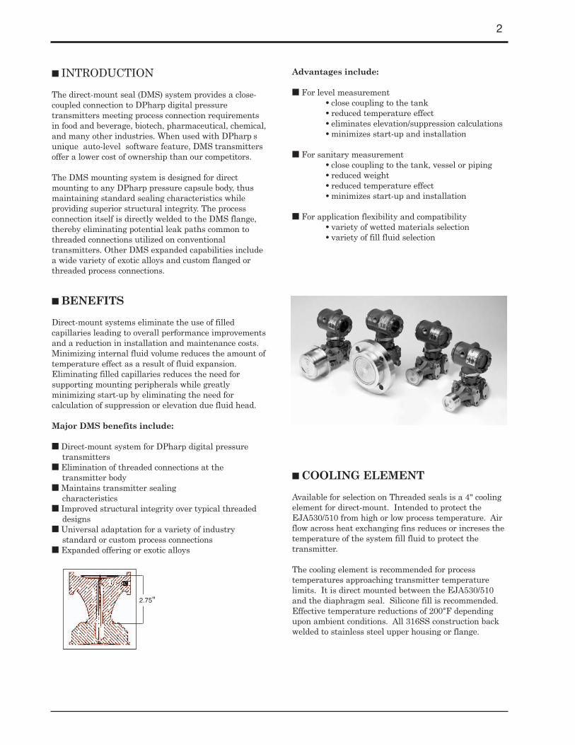
Direct-mount systems eliminate the use of filledcapillaries leading to overall performance improvementsand a reduction in installation and maintenance costs.Minimizing internal fluid volume reduces the amount oftemperature effect as a result of fluid expansion.Eliminating filled capillaries reduces the need forsupporting mounting peripherals while greatlyminimizing start-up by eliminating the need forcalculation of suppression or elevation due fluid head.
Major DMS benefits include:
■ Direct-mount system for DPharp digital pressuretransmitters
■ Elimination of threaded connections at thetransmitter body
■ Maintains transmitter sealingcharacteristics
■ Improved structural integrity over typical threadeddesigns
■ Universal adaptation for a variety of industrystandard or custom process connections
■ Expanded offering or exotic alloys
Advantages include:
■ For level measurement• close coupling to the tank• reduced temperature effect• eliminates elevation/suppression calculations• minimizes start-up and installation
■ For sanitary measurement• close coupling to the tank, vessel or piping• reduced weight• reduced temperature effect• minimizes start-up and installation
■ For application flexibility and compatibility• variety of wetted materials selection• variety of fill fluid selection
■ COOLING ELEMENT
Available for selection on Threaded seals is a 4" coolingelement for direct-mount. Intended to protect theEJA530/510 from high or low process temperature. Airflow across heat exchanging fins reduces or increses thetemperature of the system fill fluid to protect thetransmitter.
The cooling element is recommended for processtemperatures approaching transmitter temperaturelimits. It is direct mounted between the EJA530/510and the diaphragm seal. Silicone fill is recommended.Effective temperature reductions of 200°F dependingupon ambient conditions. All 316SS construction backwelded to stainless steel upper housing or flange.
2
2.75"
3
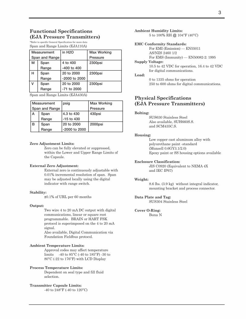
Functional Specifications (EJA Pressure Transmitters)*Refer to specific General Specification for more data
Span and Range Limits (EJA110A)
Span and Range Limits (EJA430A)
Zero Adjustment Limits: Zero can be fully elevated or suppressed,within the Lower and Upper Range Limits ofthe Capsule.
External Zero Adjustment: External zero is continuously adjustable with0.01% incremental resolution of span. Spanmay be adjusted locally using the digitalindicator with range switch.
Stability: ±0.1% of URL per 60 months
Output: Two wire 4 to 20 mA DC output with digitalcommunications, linear or square rootprogrammable. BRAIN or HART FSKprotocol is superimposed on the 4 to 20 mAsignal.Also available, Digital Communication viaFoundation Fieldbus protocol.
Ambient Temperature Limits:Approval codes may affect temperaturelimits -40 to 85°C (-40 to 185°F) -30 to 80°C (-22 to 176°F) with LCD Display
Process Temperature Limits:Dependent on seal type and fill fluid selection.
Transmitter Capsule Limits:-40 to 248°F (-40 to 120°C)
Ambient Humidity Limits: 5 to 100% RH @ 104°F (40°C)
EMC Conformity Standards: For EMI (Emission) — EN55011 AS/NZS 2460 1/2For EMS (Immunity) — EN50082-2: 1995
Supply Voltage:10.5 to 42 VDC for operation, 16.4 to 42 VDC for digital communications.
Load: 0 to 1335 ohms for operation250 to 600 ohms for digital communications.
Physical Specifications (EJA Pressure Transmitters)
Bolting: SUS630 Stainless SteelAlso available, SUH660S.S.and SCM435C.S.
Housing: Low copper cast aluminum alloy with polyurethane paint -standard(Munsell 0.6GY3.1/2.0)Epoxy paint or SS housing options available
Enclosure Classification: JIS C0920 (Equivalent to NEMA 4X and IEC IP67)
Weight: 8.6 lbs. (3.9 kg) without integral indicator, mounting bracket and process connector.
Data Plate and Tag: SUS304 Stainless Steel
Cover O-Ring: Buna N
Measurement in H2O Max WorkingSpan and Range PressureM Span 4 to 400 2300psi
Range -400 to 400H Span 20 to 2000 2300psi
Range -2000 to 2000V Span 20 to 2000 2300psi
Range -71 to 2000
Measurement psig Max WorkingSpan and Range PressureA Span 4.3 to 430 430psi
Range -15 to 430B Span 20 to 2000 2000psi
Range -2000 to 2000
4
Model NumbersThe following shows the structure of various modelnumbers in order to create the appropriate sealconfiguration for your requirements. Select therequired type of seal, and then proceed through modelnumber construction. A brief description of the basemodels is as follows;
Pancake Seal (WIKA 990.28):This type of seal is usually mounted betweentwo flange connections. It is effectivelyclamped or "sandwiched" between the twoflanges. Typical sizes are 2"-4" with 3" beingthe most common.Pressure Rating: 150# & 300# per ASME B16.5 (higher pressures available upon request)Suitable Pressure Ranges:10" H20 to maximum flange rating, depending on diaphragm size and process conditions.Operating Temperature Range:-40°F to 752°F (-40°C to 400°C)Standard Features Instrument Connection:Radial capillary up to 30 ft. (>30 ft. consult factory), SS armored SS PVC coatedProcess Connection Sealing Face:2", 3", or 4" raised face per ASME B16.5Upper Housing Material: 316SSDiaphragm Material:316SS, Hastelloy C-276, Tantalum (572°F), Monel, TitaniumInstallation:Use appropriate gasket, bolts, nuts, and blind flange per ASME B16.5 (not supplied with seal)
Flush Flanged (WIKA 990.27):This seal provides a direct flange connection,with the diaphragm welded to the sealingsurface. These are available in 2"-4" processconnections.
Pressure Rating: 150#, 300#, 600# per ASME B16.5Suitable Pressure Ranges:10" H20 to maximum flange rating, depending on diaphragm size and process conditions.Operating Temperature Range:-130°F to 752°F (-90°C to 400°C)Standard Features Instrument Connection:Direct mount or axial capillary up to 30 ft. (>30 ft. consult factory), SS armored,SS PVC coatedProcess Connection:150#, 300#, 600# flange per ASME B16.5Process Connection Sealing Face:2", 3", or 4" raised face per ASME B16.5Flange Material: 316L SSWetted Material: 316L SS, Monel, Hastelloy C-276, Tantalum, TitaniumInstallation:Use appropriate gasket, bolts, and nuts, per ASME B16.5 (not supplied with seal)
Extended Flanged (WIKA 990.29): Same basic construction as the Flush flangedexcept that the diaphragm is attached to anextended barrel which is typically used onjacketed tanks. Process connection sizes are3" and 4" with extensions available in 2", 4"and 6".Pressure Rating: 150#, 300#, 600# per ASME B16.5Suitable Pressure Ranges:10" H20 to maximum flange rating, depending on diaphragm size and process conditions.Operating Temperature Range:-130°F to 752°F (-90°C to 400°C)Standard Features Instrument Connection:Direct mount or axial capillary up to 30 ft. (>30 ft. consult factory), SS armoredSS PVC coatedProcess Connection:150#, 300#, 600# flange per ASME B16.5
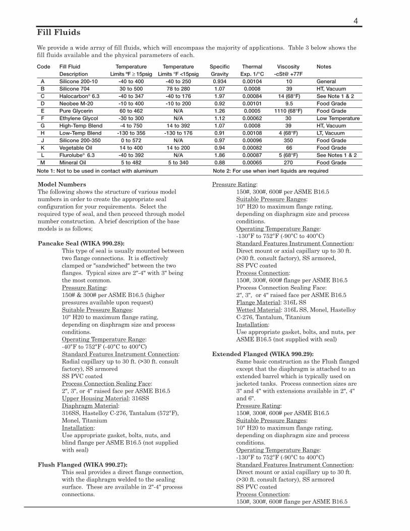
Fill Fluids
We provide a wide array of fill fluids, which will encompass the majority of applications. Table 3 below shows thefill fluids available and the physical parameters of each.
Code Fill Fluid Temperature Temperature Specific Thermal Viscosity NotesDescription Limits ºF ≥ 15psig Limits °F <15psig Gravity Exp. 1/°C -cSt@ +77F
A Silicone 200-10 -40 to 400 -40 to 250 0.934 0.00104 10 GeneralB Silicone 704 30 to 500 78 to 280 1.07 0.0008 39 HT, VacuumC Halocarbon® 6.3 -40 to 347 -40 to 176 1.97 0.00084 14 (68°F) See Note 1 & 2D Neobee M-20 -10 to 400 -10 to 200 0.92 0.00101 9.5 Food GradeE Pure Glycerin 60 to 462 N/A 1.26 0.0005 1110 (68°F) Food GradeF Ethylene Glycol -30 to 300 N/A 1.12 0.00062 30 Low TemperatureG High-Temp Blend -4 to 750 14 to 392 1.07 0.0008 39 HT, VacuumH Low-Temp Blend -130 to 356 -130 to 176 0.91 0.00108 4 (68°F) LT, VacuumJ Silicone 200-350 0 to 572 N/A 0.97 0.00096 350 Food GradeK Vegetable Oil 14 to 400 14 to 200 0.94 0.00082 66 Food GradeL Flurolube® 6.3 -40 to 392 N/A 1.86 0.00087 5 (68°F) See Notes 1 & 2M Mineral Oil 5 to 482 5 to 340 0.88 0.00065 270 Food Grade
Note 1: Not to be used in contact with aluminum Note 2: For use when inert liquids are required

5
Process Connection Sealing Face:3", or 4" raised face per ASME B16.5Diaphragm Extension Lengths:2" (50mm), 4" (100mm), 6" (150mm), Schedule 40Flange Material: 316/316L SS Extension and Raised Face Material: 316L SS, Hastelloy C-276, Monel, Tantalum (572°F)Diaphragm Material: 316L SS, Hastelloy C-276, Monel, Tantalum (572°F)Installation:Use appropriate gasket, bolts, and nuts, per ASME B16.5 (not supplied with seal)
Remote Flanged (WIKA 990.12.601): These seals use a lower housing to provide theprocess connection. A 2.4" diaphragm is used,and comes in process connection sizes of .5" to2" (>2Ó consult factory)Pressure Rating: 150#, 300#, 600# per ASME B16.5Suitable Pressure Ranges:100" H20 to maximum flange rating, depending on diaphragm size and process conditions.Operating Temperature Range:Up to 752°F (dependent upon materials)Standard Features Instrument Connection:Direct mount for EJA530/510 or axial capillary up to 30 ft. (>30 ft. consult factory), SS armored, SS PVC coatedProcess Connection:150#, 300#, 600# flange per ASME B16.5Process Connection Sealing Face:.5", 1.0", 1.5", or 2" raised face per ASME B16.5Upper Housing Material: 316SSDiaphragm: 316L SS Hastelloy C-276, Monel, Tantalum (572°F)Gasket: (between upper and lower housing)Viton, Max. temperature 400°F (204°C) used with 316L dia. (SSS), Teflon, Max. temperature 500°F (260°C) used with all othersLower Housing Material:316 SS, Hastelloy C-276, Monel, 316 SS-Tantalum-lined or TitaniumClamp, Support Ring, Nuts and Bolts:300 series SS, max. temperature 500°F (260°C)
Threaded Connection (WIKA 990.10.501): These seals also use a lower housing and comewith a 2.4" diaphragm. Process connectionsizes are available in 1/2", 3/4" and 1" NPT-Fthreads. (other sizes may beaccommodated—please call)Pressure Rating: 3675 PSISuitable Pressure Ranges: 15 PSI to 3675 PSI
Operating Temperature:Up to 752°F (dependent upon materials)Standard Features Instrument Connection:Direct mount for EJA530/510 or axial capillary up to 30 ft. (>30 ft. consult factory), SS armored, SS PVC coatedProcess Connection:.5" NPT, .75" NPT, 1" NPT (female)Upper Housing Material: 316 SSDiaphragm Material:316L SS, Hastelloy C-276, Monel, Tantalum (572°F)Gasket: (between upper and lower housing)Viton, Max. temperature 400°F (204°C) used with 316L dia. (SSS), Teflon, Max. temperature 500°F (260°C) used with all othersLower Housing Material:316 SS, Hastelloy C-276, Monel, or TitaniumClamp, Support Ring, Nuts and Bolts:300 series SS, max. temperature 500°F (260°C)
Sanitary (WIKA 990.22 & 981.22): These seals are used in processes, whichrequire quick disconnect for ease of cleaning.The connection itself does not allow collectionof material, which can potentially createbacterial growth. Process connections areavailable in TriClamp, Cherry Burrell, In-Linesanitary, Tank Spud, Aseptic, "APC" Quickconnect and GC "H" Line.Also, these seals allow for Close Coupled Connection (CCC) to the EJA 530/510 direct mount transmitters. Refer to GS1C21F1-E for product information.
Traditional:Pressure Rating: See table
Suitable Pressure Ranges:15 PSI to 600 PSI (1000 PSI) [by using the appropriate clamping device.]Operating Temperature Range:-22°F to 400°F (-30°C to 205°C)Standard Features Instrument Connection:Direct mount or axial capillary up to 30ft., SS armoredProcess Connection:1.5", 2", 2.5", 3", & 4 Tri-Clamp Cherry-Burrell I-Line and Q-Line, Aseptic connection, APC quick connect, GC H-Line, 4" tank spudUpper Housing Material:316L SS, Hastelloy C-276Diaphragm Material:316L SS, Hastelloy C-276
In-Line:Pressure Rating:
Process Material Pressure EffectiveConnection Rating Diaphragm diameter
1.5" All 316SS 600 PSI 1.3"2" All 316SS 550 PSI 1.6"
2.5" All 316SS 450 PSI 2.1"3" All 316SS 350 PSI 2.9"4" All 316SS 250 PSI 3.5"

6
600 PSI (1000 PSI) [by using the appropriate clamping device]Suitable Pressure Ranges:15 PSI to 600 PSI (1000 PSI) [by using the appropriate clamping device]Operating Temperature Range:-130°F to 752°F (-90°C to 400°C)Standard Features Instrument Connection:Direct mount for EJA530/510 or axial capillary up to 30 ft. (>30 ft. consult factory), SS armored, SS PVC coatedProcess Connection:.75", 1", 1.5", 2", 3", 4", Tri-ClampBody: 316L SS, Hastelloy C-276Diaphragm: 316L SS, Hastelloy C-276
Low-Range (WIKA 990.40 & 990.41):These seals are designed for applications with smaller measurement spans (≤ 150Ó w.c.). An expanded lower housing is used to accommodate a 3.5" diaphragm. As with other lower housing, this can also function with a flushing ring when a flushing connection is selected. Process connections are available in a variety of sizes from 1/2" to 4" in flanged-direct mount, remote flange and remote flange threaded designs.Pressure Rating:150#, 300#, 600# per ASME B16.5, or 1500 PSI-ThreadedSuitable Pressure Ranges:From 10" H20 to max. flange rating or 1500 PSI-for threaded connectionOperating Temperature Range:-40°F to 752°F (-40°C to 400°C)Standard Features Instrument Connection:Direct mount or axial capillary up to 30 ft. (>30 ft. consult factory), SS armored,SS PVC coatedProcess Connection:0.5" to 4.0" Upper Housing Material: 316 SSDiaphragm:316L SS, Hastelloy C-276, Monel, Titanium, Tantalum (max. 572°C)Gasket:Viton, max. temperature 400°F (204°F)Lower Housing Material:316 SS, Hastelloy C-276, Monel, Titanium, Tantalum lined 316Bolts:300 series SS, max. temperature 500°F (260°C)
Saddle (WIKA 910.20):These seals support a saddle weld process connection, designed for pipe line pressure measurement.Pressure Rating:1500 PSI; depending on pipe sizeSuitable Pressure Ranges:15 PSI to 1500 PSI
Operating Temperature Range:0°F to 482°F (-12°C to 250°C)Standard Features Instrument Connection:Direct mount for EJA530/510 or axial capillary up to 30 ft. (>30 ft. consult factory)Piping Size:3" to 12" pipe
Transmitter:Most typical remote seal applications are supported by the EJA110A (DP) and EJA430A (Gauge) transmitters. To meet process requirements, other DPharp transmitters can be fitted with diaphragm seals: EJA130A DP cells and EJA440A/310A/510A/530A GP/AP. Follow the model code configuration as listed in the specific instrumentÕs GS sheet.
■ Diaphragm Size
The error induced in a system can be greatly affected bydifferential temperature (between the process and the fillfluid) and by the spring constant of the diaphragm used.An error in a filled capillary system can be calculated bythe following equation:Error (in. H2O) = (˘ T) (Et) (Rs) Vt)∆T The differential temperature changeEt The coefficient of thermal expansion of the fill fluidRs The diaphragm spring constantVt The volume of the fill fluid subjected to
temperature changeThe following graph shows the comparison of two differentdiaphragm sizes and their effect on total error induced.
This does not necessarily mean that a bigger diaphragmis required. When a gauge pressure transmitter is beingused at pressures higher than 100psig, a smallerdiaphragm can be used. Also, if a system has a large ∆Tbetween the process and ambient temperature but thesystem is stable, such that this temperature difference isconstant, the two legs of the system will compensate and the error can be zeroed out of the system. the following isa quick pick chart for reference.
25
20
15
10
5
0
0 10 20 30 40 50 60 70 80 90 100
Error vs. Temperature
∆T
Err
or
H2O
2.5" seal4.0" seal
Transmitter Span Suggested DiaphragmSize
10 to 100 H2O ≥ 3"
100 to 1000 H2O ≥ 2.4"
30 to 200 psi ≥ 2"
200 to 1000 psi ≥ 1"

7
Transmitter Model Codes
Model Suffix Codes DescriptionEJA110A Differential Pressure TransmitterOutput -D 4 to 20 mA output with BRAIN protocol
-E 4 to 20 mA output with HART protocolMeasurement M 4 to 400 in H2OSpan H 20 to 2000 in H2O(Capsule) V 20 to 2000 psidWetted Parts S Hastelloy C-276 diaphragm;
SUS316SS flange, vent & drainConnection 5 1/4" NPT on cover flangeBolting B SUS630 Stainless SteelInstallation -9 Horizontal impulse pipingElectrical 2 1/2" NPT Female Electrical Connection, 2 connectionsConnection 7* same with SS Blind PlugIndication E LCD digital indicator with range switch
N Blind - No IndicatorMounting A 2" mounting bracket - Carbon Steel
B 2" mounting bracket - Stainless SteelN No bracket
Example: EJA110A-DMS5B-92EA/FF1/D1/N5 — See next page for typical seal options (refer to product GS for complete model configurations)
Model Suffix Codes DescriptionEJA430A Gauge Pressure TransmitterOutput -D 4 to 20 mA output with BRAIN protocol
-E 4 to 20 mA output with HART protocolMeasurement Span A 4.3 to 430 psig(Capsule) B 20 to 2000 psigWetted Parts S Hastelloy C-276 diaphragm;
SUS316SS flange, vent & drainConnection 5 1/4" NPT on cover flangeBolting B SUS630 Stainless SteelInstallation -9 Horizontal impulse pipingElectrical 2 1/2" NPT Female Electrical Connection, 2 connectionsConnection 7* same with SS Blind Plug Indication E LCD digital indicator with range switch
N Blind - No IndicatorMounting A 2" mounting bracket - Carbon Steel
B 2" mounting bracket - Stainless SteelN No bracket
Example: EJA430A-DAS5B-92EA/FF1/D1/N5 — See next page for typical seal options (refer to product GS for complete model configurations)
*1/2" NPT Female Electrical Connection:two connectors and a blind plug

8
■ OPTIONAL SPECIFICATIONS (Most commonly selected for North America)
Item Description CodeFM Explosionproof Approval
Explosionproof for Class I, Division 1, Groups B, C and DDust-ignitionproof for Class II/III, Division 1, Groups E, F and GHazardous (classified) locations, indoors and outdoors (NEMA 4X) /FF1Temperature class: T6
Amb. Temp.: -40 to 60…C (-40 to 140…F)Electrical connection: 1/2 NPT female*1
FM Intrinsically safe Approval*3
Intrinsically Safe for Class I, Division 1, Groups A, B, C & D, Class II, Division 1, Groups E, F & G and Class III, Division 1, Hazardous Locations
Factory Nonincendive for Class I, Division 2, Groups A, B, C & D, Class II, Division 2,Mutual (FM) Groups E, F & G, and Class III, Division 1 Hazardous Locations
Enclosure: "NEMA 4X", Temp. Class: T4, Amb. Temp.: -40 to 60…C (-40 to 140…F) /FS1Intrinsically Safe Apparatus Parameters
(Groups A, B, C, D, E, F and G)Vmax = 30 V, Imax = 165 mA, Pmax = 0.9 W, Ci = 22.5 nF, Li = 730 µH
(Groups C, D, E, F and G)Vmax = 30 V, Imax = 225 mA, Pmax = 0.9 W, Ci = 22.5 nF, Li = 730 µH
Electrical connection: 1/2 NPT female*1
Combined FF1 and FS1*3
Electrical connection: 1/2 NPT female*1 /FU1CSA Explosionproof Approval
Explosionproof for Class I, Division 1, Groups B, C and DDust-ignitionproof for Class II/III, Division 1, Groups E, F and GDivision 2 ’SEALS NOT REQUIRED’, Temp. Class: T4, T5, T6, Encl Type 4x /CF1
Canadian Max. Process Temp.: T4; 120…C (248…F), T5; 100…C (212…F), T6; 85…C (185…F)Standards Amb. Temp.: -40 to 80…C (-40 to 176…F)Association Electrical connection: 1/2 NPT female*1
(CSA) CSA Intrinsically safe Approval*3
Class I, Groups A, B, C and D, ClassII and III, Groups E, F and GEncl Type 4x, Temp. Class: T4, Amb. Temp.: -40 to 60…C (-40 to 140…F) /CS1Vmax = 30 V, Imax = 165 mA, Pmax = 0.9 W, Ci = 22.5 nF, Li = 730 µH
Electrical connection: 1/2 female*1
Combined CF1 and CS1*3
Electrical connection: 1/2 female*1 /CUILightning Transmitter power supply voltage: 10.5 to 32 V DC (10.5 to 30 V DC for intrinsically safe type, Protector 9 to 32 V DC for Fieldbus communication type) /A
Allowable current: Max. 6000 A (1X40 µs), Repeating 1000 A (1X40 µs) 100 timesOil Prohibited Degrease cleansing treatment and with fluorinated oil-filled capsule /K2Use Operating temperature -20 to 80…CCalibration P Calibration (psi unit) /D1Units*1
Stainless Steel Amplifier housing material: SCS14A stainless steel /E1Amplifier (equivalent to SUS316 cast stainless steel or ASTM CF-8M)Housing*2
Body Option *4 Assemble with low volume cover flange for remote diaphragm seal attachment /N5
*1: Applicable for electrical connection code 2 and 7.
*2: Applicable for Electrical connection code 2, 3, 4, 7, 8 and 9. Not applicable for Optional code Pl and X1.
*3: Applicable for output signal code D and E.
*4: Do Not select this option if attaching one seal to D.P. transmitter or direct-mount on D.P., G.P. or A.P..
For intrinsically safe approval, use a safety barrier certified by the testing laboratories that corresponds with parameter limits.(BARD-400 is not acceptable.)
9
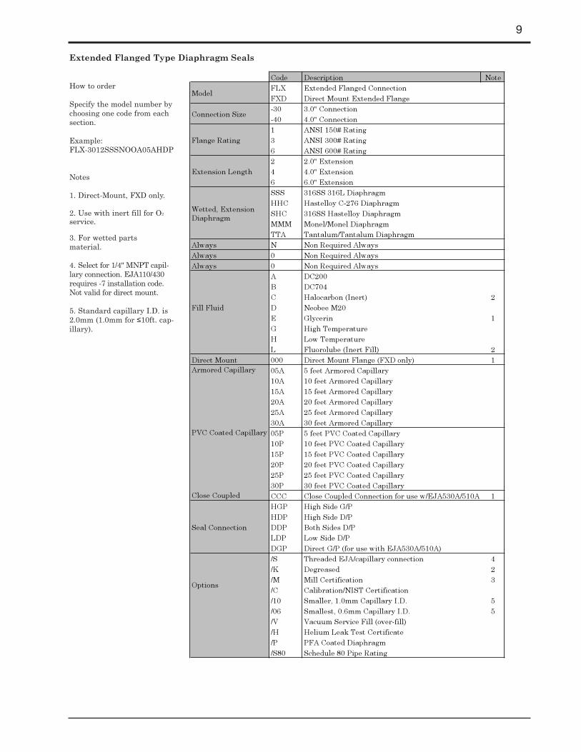
Code Description NoteFLX Extended Flanged ConnectionFXD Direct Mount Extended Flange-30 3.0" Connection-40 4.0" Connection1 ANSI 150# Rating3 ANSI 300# Rating6 ANSI 600# Rating2 2.0" Extension4 4.0" Extension6 6.0" ExtensionSSS 316SS 316L DiaphragmHHC Hastelloy C-276 DiaphragmSHC 316SS Hastelloy DiaphragmMMM Monel/Monel DiaphragmTTA Tantalum/Tantalum Diaphragm
Always N Non Required AlwaysAlways 0 Non Required AlwaysAlways 0 Non Required Always
A DC200B DC704C Halocarbon (Inert) 2D Neobee M20E Glycerin 1G High TemperatureH Low TemperatureL Fluorolube (Inert Fill) 2
Direct Mount 000 Direct Mount Flange (FXD only) 105A 5 feet Armored Capillary10A 10 feet Armored Capillary15A 15 feet Armored Capillary20A 20 feet Armored Capillary25A 25 feet Armored Capillary30A 30 feet Armored Capillary05P 5 feet PVC Coated Capillary10P 10 feet PVC Coated Capillary15P 15 feet PVC Coated Capillary20P 20 feet PVC Coated Capillary25P 25 feet PVC Coated Capillary30P 30 feet PVC Coated Capillary
Close Coupled CCC Close Coupled Connection for use w/EJA530A/510A 1HGP High Side G/PHDP High Side D/PDDP Both Sides D/PLDP Low Side D/PDGP Direct G/P (for use with EJA530A/510A)/S Threaded EJA/capillary connection 4/K Degreased 2/M Mill Certification 3/C Calibration/NIST Certification/10 Smaller, 1.0mm Capillary I.D. 5/06 Smallest, 0.6mm Capillary I.D. 5/V Vacuum Service Fill (over-fill)/H Helium Leak Test Certificate/P PFA Coated Diaphragm/S80 Schedule 80 Pipe Rating
PVC Coated Capillary
Seal Connection
Options
Armored Capillary
Model
Wetted, Extension Diaphragm
Fill Fluid
Connection Size
Flange Rating
Extension Length
How to order
Specify the model number bychoosing one code from eachsection.
Example:FLX-3012SSSNOOA05AHDP
Notes
1. Direct-Mount, FXD only.
2. Use with inert fill for O2
service.
3. For wetted parts material.
4. Select for 1/4" MNPT capil-lary connection. EJA110/430requires -7 installation code.Not valid for direct mount.
5. Standard capillary I.D. is2.0mm (1.0mm for ≤10ft. cap-illary).
Extended Flanged Type Diaphragm Seals

10
Code Description NoteFLG Flush Flanged ConnectionFGD Direct Mount Flush Flange-20 2.0" Connection-30 3.0" Connection-40 4.0" Connection1 ANSI 150# Rating3 ANSI 300# Rating6 ANSI 600# Rating
Always N AlwaysSSS 316SS/316SS/316L DiaphragmHHC 316SS/Hastelloy C-276/Hastelloy C-276 Dia.SHC 316SS/316SS/Hastelloy C-276 DiaphragmSTA 316SS/Tantalum/Tantalum DiaphragmSMM 316SS/Monel/Monel DiaphragmSTI 316SS/Titanium/Titanium Diaphragm
Always N None-Always0 NoneS 316SSH Hastelloy CM MonelE Titanium0 None1 Single 1/4" 62 Dual 1/4" 63 Single 1/2" 64 Dual 1/2" 6A DC200B DC704C Halocarbon (Inert) 2D Neobee M20E Glycerin 1G High TemperatureH Low TemperatureL Fluorolube (Inert) 2
Direct Mount 000 Direct Mount Flange (FGD only) 105A 5 feet Armored Capillary10A 10 feet Armored Capillary15A 15 feet Armored Capillary20A 20 feet Armored Capillary25A 25 feet Armored Capillary30A 30 feet Armored Capillary05P 5 feet PVC Coated Capillary10P 10 feet PVC Coated Capillary15P 15 feet PVC Coated Capillary20P 20 feet PVC Coated Capillary25P 25 feet PVC Coated Capillary30P 30 feet PVC Coated Capillary
Close Coupled CCC Close Coupled Connection for use w/EJA530A/510A 1HGP High Side GaugeHDP High Side D/PDDP Both Sides D/PLDP Low Side D/PDGP Direct G/P (for use with EJA530A/510A)/S Threaded 4/K Degreased 2/M Mill Certification 3/C Calibration/NIST Certification/10 Smaller, 1.0mm Capillary I.D. 5/06 Smallest, 0.6mm Capillary I.D. 5/T Teflon (PTFE) lined diaphragm 7/SD Step-shaped Diaphragm (>500m Bar A) 8/V Vacuum Service Fill (over-fill) 9/H Helium Leak Test Certificate
Model
Flange Rating
PVC Coated Capillary
Seal Connection
Connection Size
Diaphragm and Upper Housing/ Wetted Housing/ Diaphragm
Lower Housing Material
Flushing Connection
Fill Fluid
Options
Armored Capillary
Flush Flanged Type Diaphragm Seals
How to order
Specify the model number bychoosing one code from eachsection.
Example:FLG-301NSSSNO0A05AHDP
Notes
1. Direct-Mount, FGD only.
2. Use with inert fill for O2service.
3. For wetted parts material.
4. Select for 1/4" MNPT capil-lary connection. EJA110/430requires -7 installation code.Not valid for direct mount.
5. Standard capillary I.D. is2.0mm (0.6mm for ≤10ft. cap-illary).
6. Requires lower housing.
7. Not available on Tantalumor Titaniam dia. Max temp150° C.
8. Available wetted matÕl 316L SS, Hastelloy C andTantalum only, for 2" & 3"sizes.
9. Not available with optioncode /SD.
11
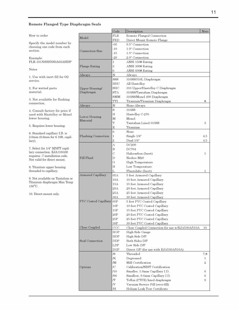
Code Description NoteFLR Remote Flanged ConnectionFRD Direct Mount Remote Flange-05 0.5" Connection-10 1.0" Connection-15 1.5" Connection-20 2.0" Connection1 ANSI 150# Rating3 ANSI 300# Rating6 ANSI 600# Rating
Always N AlwaysSSS 316SS/316L DiaphragmHHC All HastelloySHC 316 Upper/Hastelloy C DiaphragmSTA 316SS/Tantalum DiaphragmSMM 316SS/Monel 400 DiaphragmTTI Titanium/Titanium Diaphragm 8
Always N None-AlwaysS 316SSH Hastelloy C-276M MonelT Tantalum Lined 316SS 3E Titanium0 None1 Single 1/4" 4,52 Dual 1/4" 4,5A DC200B DC704C Halocarbon (Inert) 1D Neobee M20G High TemperatureH Low TemperatureL Fluorolube (Inert) 105A 5 feet Armored Capillary10A 10 feet Armored Capillary15A 15 feet Armored Capillary20A 20 feet Armored Capillary25A 25 feet Armored Capillary30A 30 feet Armored Capillary05P 5 feet PVC Coated Capillary10P 10 feet PVC Coated Capillary15P 15 feet PVC Coated Capillary20P 20 feet PVC Coated Capillary25P 25 feet PVC Coated Capillary30P 30 feet PVC Coated Capillary
Close Coupled CCC Close Coupled Connection for use w/EJA530A/510A 10HGP High Side GaugeHDP High Side D/PDDP Both Sides D/PLDP Low Side D/PDGP Direct G/P (for use with EJA530A/510A)/S Threaded 7,8/K Degreased 1/M Mill Certification 2/C Calibration/NIST Certification/10 Smaller, 1.0mm Capillary I.D. 6/06 Smallest, 0.6mm Capillary I.D. 6/T Teflon (PTFE) lined diaphragm 9/V Vacuum Service Fill (over-fill)/H Helium Leak Test Certificate
Model
Flange Rating
Connection Size
Flushing Connection
Upper Housing/ Diaphragm
Lower Housing Material
Options
Armored Capillary
Fill Fluid
PVC Coated Capillary
Seal Connection
Remote Flanged Type Diaphragm Seals
How to order
Specify the model number bychoosing one code from eachsection.
Example:FLR-101NSSSNS0A05AHDP
Notes
1. Use with inert fill for O2service.
2. For wetted parts material.
3. Not available for flushingconnection.
4. Consult factory for price ifused with Hastelloy or Monellower housing.
5. Requires lower housing.
6. Standard capillary I.D. is2.0mm (0.6mm for ≤ 10ft. capil-lary).
7. Select for 1/4" MNPT capil-lary connection. EJA110/430requires -7 installation code.Not valid for direct mount.
8. Titanium upper housingthreaded to capillary.
9. Not available on Tantalum orTitanium diaphragm Max Temp150°C.
10. Direct-mount only.
12
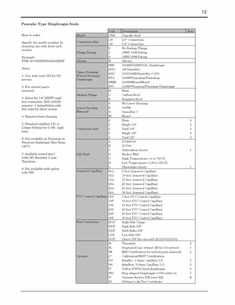
Code Description NoteModel PNK Pancake Seal
-20 2.0" Connection-30 3.0" Connection0 No Backup Flange1 ANSI 150# Rating3 ANSI 300# Rating
Always N AlwaysSSS 316SS/316SS/316L DiaphragmHHC All HastelloySHC 316/316SS/Hastelloy C-276STA 316SS/Tantalum/TantalumSMM 316SS/Monel/MonelSTI 316SS/Titanium/Titanium DiaphragmN NoneC Carbon SteelS Stainless Steel0 No Lower HousingS 316SSH Hastelloy CM Monel0 None 41 Single 1/4" 42 Dual 1/4" 43 Single 1/2" 44 Dual 1/2" 4A DC200-50B DC704C Halocarbon (Inert) 1D Neobee M20G High Temperature (-4 to 740°F)H Low Temperature (-130 to 356°F)L Fluorolube (Inert) 105A 5 feet Armored Capillary10A 10 feet Armored Capillary15A 15 feet Armored Capillary20A 20 feet Armored Capillary25A 25 feet Armored Capillary30A 30 feet Armored Capillary05P 5 feet PVC Coated Capillary10P 10 feet PVC Coated Capillary15P 15 feet PVC Coated Capillary20P 20 feet PVC Coated Capillary25P 25 feet PVC Coated Capillary30P 30 feet PVC Coated CapillaryHGP High Side GaugeHDP High Side D/PDDP Both Sides D/PLDP Low Side D/PDGP Direct G/P (for use with EJA530A/510A)/S Threaded 3/K Degreased (use w/inert fill for O2 service) 1/M Mill Certification for wetted parts material 2/C Calibration/NIST Certification/10 Smaller, 1.0mm Capillary I.D. 5/06 Smallest, 0.6mm Capillary I.D. 5/T Teflon (PTFE) lined diaphragm 6/SD Step-shaped Diaphragm (>500 mBar A) 7/V Vacuum Service Fill (over-fill) 8/H Helium Leak Test Certificate
Options
Armored Capillary
Flange Rating
PVC Coated Capillary
Seal Connection
Upper Housing/ Wetted Housing/ Diaphragm
Fill Fluid
Connection Size
Connection Size
Backup Flange
Lower Housing Material
Pancake Type Diaphragm Seals
How to order
Specify the model number bychoosing one code from eachsection.
Example:PNK-301NSSSNO0A05AHDP
Notes
1. Use with inert fill for O2service.
2. For wetted parts material.
3. Select for 1/4" MNPT capil-lary connection. EJA 110/430requires -7 instqallation code.Not valid for direct mount.
4. Requires lower housing.
5. Standard capillary I.D. is2.0mm (0.6mm for ≤ 10ft. capil-lary).
6. Not available on Tantalum orTitanium diaphragm Max Temp150°C.
7. Available wetted matÕl 316L SS, Hastelloy C andTantalum.
8. Not available with optioncode /SD.

13
Code Description NoteSTC Sanitary Tri-ClampCBI Cherry Burrell "I" LineCBQ Cherry Burrell "Q" LineSNL Sanitary In-LineTSP Tank Spud (4" only) 6ASP Aseptic ConnectionAPC "APC" Quick ConnectGCH GC "H" LineSTD Direct Mount Tri-ClampCID Direct Mount Cherry Burrell "I" LineCQD Direct Mount Cherry Burrell "Q" LineTSD Direct Mount Tank Spud (4") 6ASD Direct Mount AsepticAPD Direct Mount "APC"GHD Direct Mount GC "H"-TB 3/4" (Sanitary In-Line only) 1-TC 1.0" (Sanitary In-Line only) 1-TD 1.5" (Sanitary In-Line only) 1-TE 2.0" (Sanitary In-Line only) 1-TF 3.0" (Sanitary In-Line only) 1-TG 4.0" (Sanitary In-Line only) 1-15 1.5" Connection-20 2.0" Connection-25 2.5" Connection 2-30 3.0" Connection-40 4.0" Connection 2S SanitaryF 20 RA Finish (Electro-Polish)L Sanitary In-Line - 20RA Finish 1N None2 2.0" Extension (TSP/TSD only) 66 6.0" Extension (TSP/TSD only) 6SSS 316SS/316L DiaphragmHHC All Hastelloy 2
Always N Non required0 None2 2" ext. Tank Spud Sleeve (TSP/TSD only)6 6" ext. Tank Spud Sleeve (TSP/TSD only)
Always 0 No Lower HousingD Neobee M20E Glycerin 4J DC200 - 350 (Food Grade)K Vegetable OilM Mineral Oil
Direct Mount 000 Direct Mount Flange 405A 5 feet Armored Capillary10A 10 feet Armored Capillary15A 15 feet Armored Capillary20A 20 feet Armored Capillary25A 25 feet Armored Capillary30A 30 feet Armored Capillary05P 5 feet PVC Coated Capillary10P 10 feet PVC Coated Capillary15P 15 feet PVC Coated Capillary20P 20 feet PVC Coated Capillary25P 25 feet PVC Coated Capillary30P 30 feet PVC Coated Capillary
Close Coupled CCC Close Coupled Connection for use w/EJA530A/510A 4HGP High Side GaugeHDP High Side D/PDDP Both Sides D/PLDP Low Side D/PDGP Direct G/P (for use with EJA530A/510A)/S Threaded 5/M Mill Certification 3/C Calibration/NIST Certification/10 Smaller, 1.0mm Capillary I.D. 7/06 Smallest, 0.6mm Capillary I.D. 7/P Tank Spud Clamp (TSP/TSD only)/A EPDM O-Ring (tank spud only)/V Vacuum Service Fill (over-fill)/H Helium Leak Test Certificate
Model
PVC Coated Capillary
Armored Capillary
Extension Length
Upper Housing/ Diaphragm
Fill Fluid
Tank Spud Sleeve
Connection Size
Connection Rating
Seal Connection
Options
Sanitary Type Diaphragm Seals
How to order
Specify the model number bychoosing one code from eachsection.
Example:STC-20SNSSSN00D05AHDP
Notes
1. Sanitary in-line only.
2. Not available on sanitaryin-line.
3. For wetted parts material.
4. Direct Mount only.
5. Select for 1/4" MNPT capil-lary connection. EJA 110/430requires -7 installation code.Not valid for direct mount.
6. TSP and TSD require 2.0" or6.0" extension length selection.
7. Standard capillary I.D. is 2.0mm (1.0mm for ≤10ft. capil-lary).
14
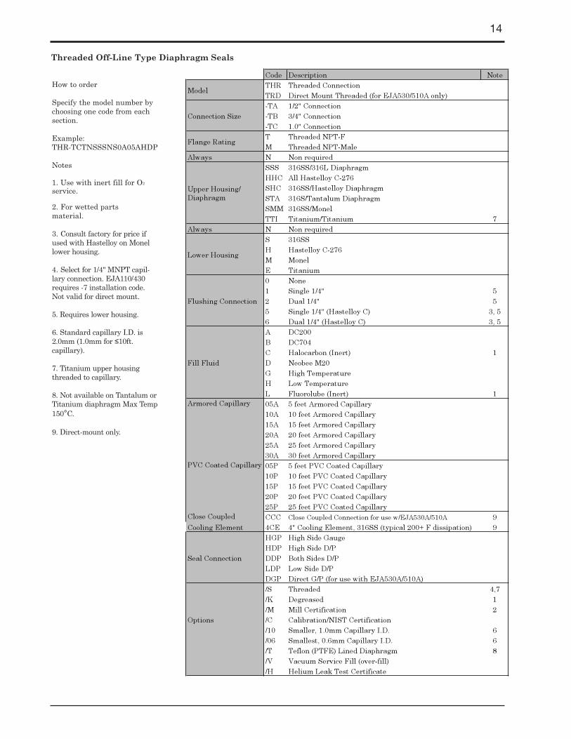
Code Description NoteTHR Threaded ConnectionTRD Direct Mount Threaded (for EJA530/510A only)-TA 1/2" Connection-TB 3/4" Connection-TC 1.0" ConnectionT Threaded NPT-FM Threaded NPT-Male
Always N Non requiredSSS 316SS/316L DiaphragmHHC All Hastelloy C-276SHC 316SS/Hastelloy DiaphragmSTA 316S/Tantalum DiaphragmSMM 316SS/MonelTTI Titanium/Titanium 7
Always N Non requiredS 316SSH Hastelloy C-276M MonelE Titanium 0 None1 Single 1/4" 52 Dual 1/4" 55 Single 1/4" (Hastelloy C) 3, 56 Dual 1/4" (Hastelloy C) 3, 5A DC200B DC704C Halocarbon (Inert) 1D Neobee M20G High TemperatureH Low TemperatureL Fluorolube (Inert) 105A 5 feet Armored Capillary10A 10 feet Armored Capillary15A 15 feet Armored Capillary20A 20 feet Armored Capillary25A 25 feet Armored Capillary30A 30 feet Armored Capillary
PVC Coated Capillary 05P 5 feet PVC Coated Capillary10P 10 feet PVC Coated Capillary15P 15 feet PVC Coated Capillary20P 20 feet PVC Coated Capillary25P 25 feet PVC Coated Capillary
Close Coupled CCC Close Coupled Connection for use w/EJA530A/510A 9Cooling Element 4CE 4" Cooling Element, 316SS (typical 200+°F dissipation) 9
HGP High Side GaugeHDP High Side D/PDDP Both Sides D/PLDP Low Side D/PDGP Direct G/P (for use with EJA530A/510A)/S Threaded 4,7/K Degreased 1/M Mill Certification 2/C Calibration/NIST Certification/10 Smaller, 1.0mm Capillary I.D. 6/06 Smallest, 0.6mm Capillary I.D. 6/T Teflon (PTFE) Lined Diaphragm 8/V Vacuum Service Fill (over-fill)/H Helium Leak Test Certificate
Options
Fill Fluid
Armored Capillary
Seal Connection
Lower Housing
Flushing Connection
Model
Connection Size
Flange Rating
Upper Housing/ Diaphragm
Threaded Off-Line Type Diaphragm Seals
How to order
Specify the model number bychoosing one code from eachsection.
Example:THR-TCTNSSSNS0A05AHDP
Notes
1. Use with inert fill for O2
service.
2. For wetted parts material.
3. Consult factory for price ifused with Hastelloy on Monellower housing.
4. Select for 1/4" MNPT capil-lary connection. EJA110/430requires -7 installation code.Not valid for direct mount.
5. Requires lower housing.
6. Standard capillary I.D. is2.0mm (1.0mm for ≤10ft. capillary).
7. Titanium upper housingthreaded to capillary.
8. Not available on Tantalum orTitanium diaphragm Max Temp150°C.
9. Direct-mount only.
15
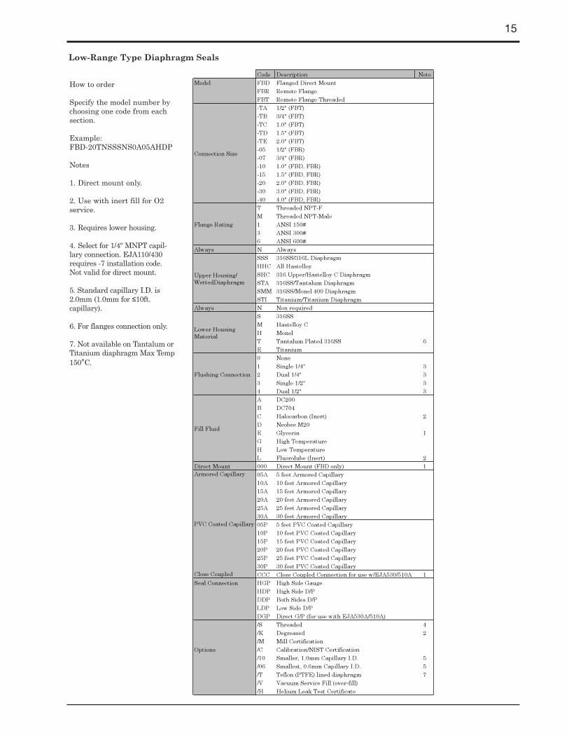
Code Description NoteModel FBD Flanged Direct Mount
FBR Remote FlangeFBT Remote Flange Threaded-TA 1/2" (FBT)-TB 3/4" (FBT)-TC 1.0" (FBT)-TD 1.5" (FBT)-TE 2.0" (FBT)-05 1/2" (FBR)-07 3/4" (FBR)-10 1.0" (FBD, FBR)-15 1.5" (FBD, FBR)-20 2.0" (FBD, FBR)-30 3.0" (FBD, FBR)-40 4.0" (FBD, FBR)T Threaded NPT-FM Threaded NPT-Male1 ANSI 150#3 ANSI 300#6 ANSI 600#
Always N AlwaysSSS 316SS/316L DiaphragmHHC All HastelloySHC 316 Upper/Hastelloy C DiaphragmSTA 316SS/Tantalum DiaphragmSMM 316SS/Monel 400 DiaphragmSTI Titanium/Titanium Diaphragm
Always N Non requiredS 316SSM Hastelloy CH MonelT Tantalum Plated 316SS 6E Titanium0 None1 Single 1/4" 32 Dual 1/4" 33 Single 1/2" 34 Dual 1/2" 3A DC200B DC704C Halocarbon (Inert) 2D Neobee M20E Glycerin 1G High TemperatureH Low TemperatureL Fluorolube (Inert) 2
Direct Mount 000 Direct Mount (FBD only) 105A 5 feet Armored Capillary10A 10 feet Armored Capillary15A 15 feet Armored Capillary20A 20 feet Armored Capillary25A 25 feet Armored Capillary30A 30 feet Armored Capillary05P 5 feet PVC Coated Capillary10P 10 feet PVC Coated Capillary15P 15 feet PVC Coated Capillary20P 20 feet PVC Coated Capillary25P 25 feet PVC Coated Capillary30P 30 feet PVC Coated Capillary
Close Coupled CCC Close Coupled Connection for use w/EJA530/510A 1Seal Connection HGP High Side Gauge
HDP High Side D/PDDP Both Sides D/PLDP Low Side D/PDGP Direct G/P (for use with EJA530A/510A)/S Threaded 4/K Degreased 2/M Mill Certification/C Calibration/NIST Certification/10 Smaller, 1.0mm Capillary I.D. 5/06 Smallest, 0.6mm Capillary I.D. 5/T Teflon (PTFE) lined diaphragm 7/V Vacuum Service Fill (over-fill)/H Helium Leak Test Certificate
Upper Housing/ WettedDiaphragm
Connection Size
Flange Rating
Options
PVC Coated Capillary
Lower Housing Material
Flushing Connection
Fill Fluid
Armored Capillary
Low-Range Type Diaphragm Seals
How to order
Specify the model number bychoosing one code from eachsection.
Example:FBD-20TNSSSNS0A05AHDP
Notes
1. Direct mount only.
2. Use with inert fill for O2service.
3. Requires lower housing.
4. Select for 1/4" MNPT capil-lary connection. EJA110/430requires -7 installation code.Not valid for direct mount.
5. Standard capillary I.D. is2.0mm (1.0mm for ≤10ft. capillary).
6. For flanges connection only.
7. Not available on Tantalum orTitanium diaphragm Max Temp150°C.
16
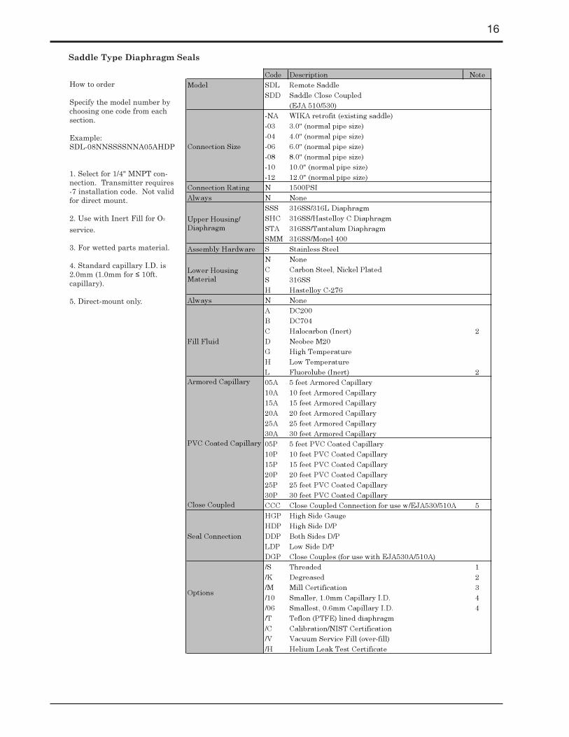
Code Description NoteModel SDL Remote Saddle
SDD Saddle Close Coupled(EJA 510/530)
-NA WIKA retrofit (existing saddle)-03 3.0" (normal pipe size)-04 4.0" (normal pipe size)-06 6.0" (normal pipe size)-08 8.0" (normal pipe size)-10 10.0" (normal pipe size)-12 12.0" (normal pipe size)
Connection Rating N 1500PSIAlways N None
SSS 316SS/316L DiaphragmSHC 316SS/Hastelloy C DiaphragmSTA 316SS/Tantalum DiaphragmSMM 316SS/Monel 400
Assembly Hardware S Stainless SteelN NoneC Carbon Steel, Nickel PlatedS 316SSH Hastelloy C-276
Always N NoneA DC200B DC704C Halocarbon (Inert) 2D Neobee M20G High TemperatureH Low TemperatureL Fluorolube (Inert) 205A 5 feet Armored Capillary10A 10 feet Armored Capillary15A 15 feet Armored Capillary20A 20 feet Armored Capillary25A 25 feet Armored Capillary30A 30 feet Armored Capillary05P 5 feet PVC Coated Capillary10P 10 feet PVC Coated Capillary15P 15 feet PVC Coated Capillary20P 20 feet PVC Coated Capillary25P 25 feet PVC Coated Capillary30P 30 feet PVC Coated Capillary
Close Coupled CCC Close Coupled Connection for use w/EJA530/510A 5HGP High Side GaugeHDP High Side D/PDDP Both Sides D/PLDP Low Side D/PDGP Close Couples (for use with EJA530A/510A)/S Threaded 1/K Degreased 2/M Mill Certification 3/10 Smaller, 1.0mm Capillary I.D. 4/06 Smallest, 0.6mm Capillary I.D. 4/T Teflon (PTFE) lined diaphragm/C Calibration/NIST Certification/V Vacuum Service Fill (over-fill)/H Helium Leak Test Certificate
Fill Fluid
Seal Connection
Options
Connection Size
Upper Housing/ Diaphragm
PVC Coated Capillary
Armored Capillary
Lower Housing Material
Saddle Type Diaphragm Seals
How to order
Specify the model number bychoosing one code from eachsection.
Example:SDL-08NNSSSSNNA05AHDP
1. Select for 1/4" MNPT con-nection. Transmitter requires-7 installation code. Not validfor direct mount.
2. Use with Inert Fill for O2
service.
3. For wetted parts material.
4. Standard capillary I.D. is2.0mm (1.0mm for ≤ 10ft. capillary).
5. Direct-mount only.
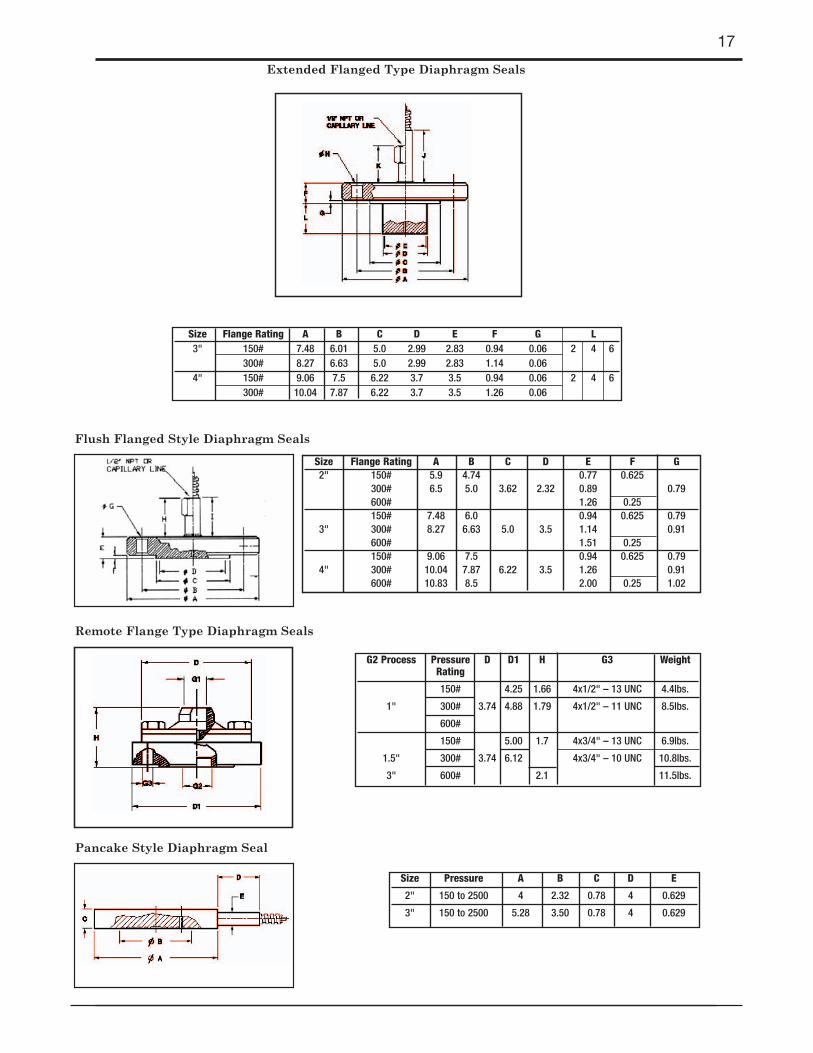
Size Flange Rating A B C D E F G L3" 150# 7.48 6.01 5.0 2.99 2.83 0.94 0.06 2 4 6
300# 8.27 6.63 5.0 2.99 2.83 1.14 0.064" 150# 9.06 7.5 6.22 3.7 3.5 0.94 0.06 2 4 6
300# 10.04 7.87 6.22 3.7 3.5 1.26 0.06
17
Size Pressure A B C D E
2" 150 to 2500 4 2.32 0.78 4 0.629
3" 150 to 2500 5.28 3.50 0.78 4 0.629
G2 Process Pressure D D1 H G3 WeightRating
150# 4.25 1.66 4x1/2" – 13 UNC 4.4lbs.
1" 300# 3.74 4.88 1.79 4x1/2" – 11 UNC 8.5lbs.
600#
150# 5.00 1.7 4x3/4" – 13 UNC 6.9lbs.
1.5" 300# 3.74 6.12 4x3/4" – 10 UNC 10.8lbs.
3" 600# 2.1 11.5lbs.
Size Flange Rating A B C D E F G2" 150# 5.9 4.74 0.77 0.625
300# 6.5 5.0 3.62 2.32 0.89 0.79600# 1.26 0.25150# 7.48 6.0 0.94 0.625 0.79
3" 300# 8.27 6.63 5.0 3.5 1.14 0.91600# 1.51 0.25150# 9.06 7.5 0.94 0.625 0.79
4" 300# 10.04 7.87 6.22 3.5 1.26 0.91600# 10.83 8.5 2.00 0.25 1.02
Extended Flanged Type Diaphragm Seals
Flush Flanged Style Diaphragm Seals
Pancake Style Diaphragm Seal
Remote Flange Type Diaphragm Seals

18
Size Weight A C D E
1.5" 1.33lbs. 1.5 1.71 1.97 1.38
2" 1.67lbs. 1.5 2.22 2.52 1.38
3" 2.00lbs. 2.52 2.78 3.05 1.38G2 Process Connection D D1 H
1/2" 1.18 2.2
3/4" 3.74 1.41 2.36
1" 1.77 3.46
Sanitary Tri-Clamp Diaphragm Seals
Tank Spud Diaphragm Seals
Threaded Off-Line Diaphragm Seals

Saddle Diaphragm Seals
19
Connection Radius R To Fit Pipe Size Pipe Outer DiameterC in mm in mm in mm
1.49 38 2.5 65 3.00 76.11.77 45 3.0 80 3.50 88.92.24 57 100 4.0 4.50 114.3
1/4” 2.76 70 5.0 125 5.5 139.7or 1/2” 3.35 85 6.0 150 6.63 168.3
NPT female 4.31 109.5 8.0 200 8.63 219.15.37 136.5 10.0 250 10.75 273.06.38 162 12.0 300 12.75 323.87.0 177.8 14.0 350 14.75 374.6

20
Printed in USA 01/04 IMPFIBU 0017