Embed Size (px)
Citation preview

GeneralSpecifications
<<Contents>> <<Index>>
OVERVIEWThe DX200 is a DAQSTATION that displays real-timemeasured data on a color LCD and saves data on a 3.5-inch floppy disk. It can be hooked up to network viaEthernet, which enables to inform by E-mail and tomonitor on Web site as well as to transfer files by usingFTP. Also, it can communicate with FOUNDATIONTM
Fieldbus and Modbus.
It comes with a four, eight, ten, twenty-channel or thirty-channel model. As the input signal, a DC voltage,thermocouple, resistance temperature detector, orcontact signal can be set to each channel. The datasaved on a floppy disk can be converted by dataconversion software to Lotus 1-2-3, Excel, or ASCIIformat file, facilitating processing on a PC. Not only this,the Viewer software allows a PC to display waveformson its screen and to print out waveforms.
STANDARD SPECIFICATIONS
General Specifications
ConstructionMounting : Flush panel mounting (on a vertical plane)
Mounting may be inclined downward up to30 degrees from a horizontal plane.
Allowable Panel Thickness :2 to 26 mm
Material : Case : drawn steelBezel : polycarbonateFront filter : polycarbonate
Case Color :Case : Grayish blue green
(Munsell 2.0B 5.0/1.7 or equivalent)Bezel : Charcoal grey light
(Munsell 10B 3.6/0.3 or equivalent)Front Panel :
Water and dust-proof(based on IEC529-IP65, NEMA No. 250TYPE 4 (except external icing test))
Dimensions :288(W) x 288(H) x 220(D) mm
Weight : DX204 : approx. 6.6 kgDX208 : approx. 6.8 kgDX210 : approx. 6.6 kgDX220 : approx. 6.9 kgDX230 : approx. 7.3 kg
InputNumber of Inputs :
DX204 : four channelsDX208 : eight channelsDX210 : ten channelsDX220 : twenty channelsDX230 : thirty channels
Measurement Interval :DX204, DX208 : 125 msDX210, DX220, DX230 : 1 s (2 s when an
A/D integration time is set to 100 ms)
GS 04L02A01-00E
GS 04L02A01-00E©Copyright August. 1999
7th Edition July. 2004(KP)
Inputs : DCV (DC voltage), TC (thermocouple), RTD(resistance temperature detector), DI (digitalinput for event recording), DCA (DC currentwith external shunt resistor attached)
Input type Range20 mV60 mV200 mV2 V6 V20 V50 VR*1
S*1
B*1
K*1
E*1
J*1
T*1
N*1
W*2
L*3
U*3
Pt100*4
JPt100*4
DCV input(TTL)Contact input
0.0 to 1760°C0.0 to 1760°C0.0 to 1820°C–200.0 to 1370°C–200.0 to 800°C–200.0 to 1100°C–200.0 to 400°C0.0 to 1300°C0.0 to 2315°C–200.0 to 900°C–200.0 to 400°C–200.0 to 600°C–200.0 to 550°COFF : less than 2.4 VON : more than 2.4 VContact on/off
DCV
TC
RTD*5
DI
*1 R, S, B, K, E, J, T, N : IEC584-1 (1995), DIN IEC584, JIS C1602-1995*2 W : W-5% Rd/W-26% Rd (Hoskins Mfg. Co.), ASTM E988*3 L : Fe-CuNi, DIN43710, U : Cu-CuNi, DIN43710*4 Pt100 : JIS C1604-1997, IEC751-1995, DIN IEC751-1996 JPt100 : JIS C1604-1989, JIS C1606-1989*5 Measuring current : i = 1 mA
32 to 3200°F32 to 3200°F32 to 3200°F–328 to 2498°F–328.0 to 1472.0°F–328.0 to 2012.0°F–328.0 to 752.0°F32 to 2372°F–328.0 to 4199°F–328.0 to 1652.0°F–328.0 to 752.0°F–328.0 to 1112.0°F–328.0 to 1022.0°F
Measuring range–20.00 to 20.00 mV–60.00 to 60.00 mV–200.0 to 200.0 mV–2.000 to 2.000 V–6.000 to 6.000 V–20.00 to 20.00 V–50.00 to 50.00 V
A/D Integration Time :Fixed to 20 ms (50 Hz), 16.7 ms (60 Hz),100ms (50/60Hz for DX210/220/230), orAUTO selectable (automatic selection bydetection of power supply frequency)
DAQSTATIONDX200

2
All Rights Reserved. Copyright © 1999, Yokogawa Electric Corporation
<<Contents>> <<Index>>
GS 04L02A01-00E
Thermocouple Burnout :Burnout upscale/downscale function can beswitched on/off (for each channel).Burnout upscale/downscale selectable
Filter :DX204, DX208 :
On/off selectable for each channelTime constant : selectable from 2, 5, and10 seconds
DX210, DX220, DX230 :moving average on/off selectable for eachchannel, moving average cycles 2 to 16selectable
Calculation :Differential computation :
Between any two channelsAvailable for DCV, TC, and RTD ranges.
Linear scaling :Available for DCV, TC, and RTD ranges.Scaling limits : –30000 to 30000Decimal point : user-selectableEngineering unit : user-definable, up to 6
charactersSquare root :
Available for DCV range.Scaling limits : –30000 to 30000Decimal point : user-selectableEngineering unit : user-definable, up to 6
characters
DisplayDisplay unit :
10.4-inch TFT color LCD(VGA, 640 x 480 pixels)
Note In the part of crystal display, there are some pixelsthat can’t always turn on or off. Please understandthat the brightness of screen looks uneven becauseof characteristics of crystal display, but it is not outof order.
Display color :Trend/Bargraph :
Selectable from 30 colorsBackground :
White or black selectableTrend display :
Trend display direction :vertical or horizontal selectable
Number of indication channels :10 channels per display (maximum)
All channels indication :30 channels (maximum)
Number of display :4 displays (4 group)
Line width : 1, 2, and 3 pixels selectableWaveform span rate :
DX204, DX208 :15, 30 sec.,1, 2, 5, 10, 20, 30 min., 1, 2,4, 10 hours/div selectable
DX 210, 220, 230 :1, 2, 5, 10, 20, 30 min., 1, 2, 4, 10 hours/div selectable
Bargraph display :Direction : Vertical or horizontal selectableNumber of indication channels :
10 channels per displayNumber of display :
4 displays (4 group)Scales : 4 to 12 selectable
Reference position :Left, right or center (only for horizontal)
Display renewal rate : 1 sDigital indication :
Number of indication channels :10 channels per display
Number of display :4 displays (4 group)
Display renewal rate : 1 sOverview display :
Number of indication channels :Measuring values and alarm status of allchannels
Information display :Alarm summary display :
Display the list of alarm summaryMessage summary display :
Display the list of messages and time.Jump to trend display by cursor pointing.
Memory information :Display the file list in internal memory.Jump to trend display by cursor pointing.
Medium information :Display the file list in external memory.Jump to trend display by cursor pointing.
Tags :Number of characters :
16 characters maximumOther display contents :
Memory status, Scale values, (0 and 100%,display on/off selectable), Scales (maximum10 scales), grid lines (number of divisionsselectable from 4 to 12), hour : minutes ongrid, trip levels (line widths are selectablefrom 1, 2 and 3 pixels), messages (up toeight different messages of up to 16characters for each), alarm indication
Data referencing function :Display the retrieved data (display data or event data)from internal or external memory.
Display format :Whole display or divided to 2 areas
Time axis operation :Display magnification or reduction, scrollby key operation
Display auto scroll function :Display group of monitor display (trenddisplay, bargraph display and digital display)automatically changes in a preset interval (5,10, 20, 30, s and 1 min).
LCD saver function :The LCD backlight automatically dims if nokey is touched for a certain preset time (canbe set from 1, 2, 5, 10, 20, and 60 min).
Temperature unit :°C or °F selectable
Language : English, French and German selectable
Data Saving FunctionExternal storage medium :
Selectable from :1) 3.5-inch floppy disk (2HD, 1.44 MB)2) PCMCIA ATA flash memory card3) Zip disk
Saving method :Manual or automatic selectable
Manual saving :Data saving by inserting external memorymedium
7th Edition July 30,2004-00

3<<Contents>> <<Index>>
All Rights Reserved. Copyright © 1999, Yokogawa Electric Corporation GS 04L02A01-00E
Automatic saving :Display data :
Periodic saving (10 min to 31 days) or keyoperation to external memory
Event data :In case of trigger free...Periodic saving (3min to 31 days) or key operation toexternal memoryIn case of using trigger...Save the datawhen sampling is finished
Data Saving Period :Display data file :
Linked with the waveform span rateEvent file : Linked with the specified sampling period
Event File Sampling Period :DX204, DX208 :
Selectable from 125, 250, 500 ms, and 1,2, 5, 10, 30, 60, 120, 300, and 600 s
DX210, DX220, DX230 :Selectable from 1, 2, 5, 10, 30, 60, 120,300, and 600 s
Measurement data File :The following two file types can be created.• Event file (stores instantaneous values sampled
periodically at a specified sampling rate)• Display data file (stores the maximum and minimum
values for each waveform span rate fromamong measured data sampled atmeasurement intervals)
Files can be created in the following combinations.(a) Event file (only for trigger mode) + display data file(b) Display data file only(c) Event file only
Data format : YOKOGAWA standard format (Binary)Data per channel :
Display data file : Measurement data...4byte/data, mathematical data...8 byte/dataEvent data file : Measurement data...2byte/data, mathematical data...4 byte/data
Sampling time :The sampling time per file (or floppy disk) duringmanual data saving can be determined by the formula“number of data items per channel x interval of datasaving.”This logic is explained in more detail below :1) When handling display data files only
If we assume that the number of measuringchannels is 20, the number of computing channelsis 10, and the display update interval is 30 min/div(60 sec waveform span rate), then :
Number of data items per channel = 1,200,000bytes/(20 x 4 bytes + 10 x 8 bytes) = 7,500 dataitems**Maximum number of data is 100,000.Sampling time per file = 7,500 x 60 sec =450,000 sec = approx. 5 days
2) When handling event files onlyIf we assume that the number of measuringchannels is 20, the number of computing channelsis 10, and the data saving interval is 1 sec, then :
Number of data items per channel = 1,200,000bytes/(20 x 2 bytes + 10 x 4 bytes) = 15,000data items**Maximum number of data is 120,000.Sampling time per file = 15,000 x 1 sec =15,000 sec = approx. 4 hours
3) When handling both display data files and eventfilesThe sampling time is calculated by defining the sizeof data items in a display data file as 900,000 bytesand the size of data items in an event data file as300,000 bytes. The method of calculation is thesame as shown above.
*Maximum number of data for display data file is75,000.
Maximum number of data for event file is 30,000.If a Zip drive or an ATA memory card is being used,at least two volumes of the above-mentioned files(the quantity depends on the medium’s capacity)are saved in that medium.
Examples of Sampling Time :
In case measurement ch = 4 ch, mathematical ch = 0 ch
Only display data file
Waveform span rate (min/div)Data saving period (s)Sampling time
1 min
2 s
41 h
5 min
10 s
8 days
20 min
40 s
34 days
30 min
60 s
52 days
60 min
120 s
104 days
240 min
480 s
416 days
Only event data file
Data saving periodSampling time
125ms4.2 h
500ms16 h
1 s33 h
5 s6 days
30 s41 days
120 s166 days
Display data fileDisplay data file + Event data file
Waveform span rate (min/div)Data saving period (s)Sampling time
1 min
2 s
31 h
5 min
10 s
6 days
20 min
40 s
26 days
30 min
60 s
39 days
60 min
120 s
78 days
240 min
480 s
312 days
Event data file
Data saving periodSampling time
125ms1 h
500ms4.2 h
1 s8.3 h
5 s41 h
30 s10 days
120 s41 days
In case measurement ch = 6 ch, mathematical ch = 0 ch
Only display data file
Waveform span rate (min/div)Data saving period (s)Sampling time
1 min
2 s
27 h
5 min
10 s
5 days
20 min
40 s
23 days
30 min
60 s
34 days
60 min
120 s
69 days
240 min
480 s
277 days
Only event data file
Data saving periodSampling time
10 s11 days
5 s5 days
1 s27 h
30 s34 days
60 s69 days
120 s138 days
Display data fileDisplay data file + Event data file
Waveform span rate (min/div)Data saving period (s)Sampling time
1 min
2 s
20 h
5 min
10 s
4 days
20 min
40 s
17 days
30 min
60 s
26 days
60 min
120 s
52 days
240 min
480 s
208 days
Event data file
Data saving periodSampling time
10 s2 days
5 s34 h
1 s6.9 h
30 s8 days
60 s17 days
120 s34 days
(approx.)
(approx.)
(approx.)
(approx.)
(approx.)
(approx.)
(approx.)
(approx.)
3rd Edition February.19,2001-00

4
All Rights Reserved. Copyright © 1999, Yokogawa Electric Corporation
<<Contents>> <<Index>>
GS 04L02A01-00E
In case measurement ch = 30 ch, mathematical ch = 0 ch
Only display data file
Waveform span rate (min/div)
Data saving period (s)
Sampling time
1 min
2 s
5.6 h
5 min
10 s
27 h
20 min
40 s
4 days
30 min
60 s
6 days
60 min
120 s
13 days
240 min
480 s
55 days
Only event data fileData saving periodSampling time
10 s2 days
5 s27 h
1 s5.6 h
30 s6 days
60 s13 days
120 s27 days
Display data fileDisplay data file + Event data file
Waveform span rate (min/div)
Data saving period (s)
Sampling time
1 min
2 s
4.2 h
5 min
10 s
20 h
20 min
40 s
3 days
30 min
60 s
5 days
60 min
120 s
10 days
240 min
480 s
41 days
Event data file
Data saving periodSampling time
10 s13 h
5 s6.9 h
1 s1.4 h
30 s41 h
60 s3 days
120 s6 days
Manual sample data :Trigger : Key operation or remote contactData format :
ASCIIMax. number of data :
50 dataTLOG data (only for MATH option) :
Trigger : Time up of TLOG intervalReport data (only for MATH option) :
Types : Hourly, daily, hourly + daily, daily + weekly,and daily + monthly
Data format :ASCII
Trigger function :Event file : Selectable from FREE, TRIG or ROTATEDisplay data file + Event file :
Selectable from TRIG or ROTATEDisplay hard copy :
Trigger : Key operationData format :
png formatOutput : External memory medium or communica-
tion interface
Alarm FunctionNumber of alarm levels :
Up to four levels for each channelAlarm types :
High and low limits, differential high and lowlimits, high and low rate-of-change limits anddelay high and low
Alarm delay time :1 to 3600 s
Interval time of rate-of-change alarms :The measurement interval times 1 to 15
Display : The alarm status (type) is displayed in thedigital value display area upon occurrence ofan alarm. A common alarm indication isalso displayed. The alarming behavior: non-hold or hold-type can be selectable forcommon to all channels.
Hysteresis :On (0.5% of display span)/off selectable(common to all channels and alarm levels)
3rd Edition February.19,2001-00
Outputs :Number of points :
2, 4, 6, 12, or 24 points (optional)Relay action :
Energized/deenergized and hold/non-holdselectable.
Memory : The times of alarm occurrences/recoveries,alarm types, etc. are stored in the memory.(Up to 120 latest alarm events are stored.)
Communication FunctionsConnection :
Ethernet (10BASE-T)Protocols : SMTP, HTTP1.0, FTP, TCP, UDP, IP, ARP,
ICMPE-mail inform function :
Recipient address :2 address groups (plural address can beput within 150 words in each groups)
Kinds of inform :the followidG information can be informedby E-mail, selectable from inform/misin-form for each group
Alarm inform :inform in occurring alarm/canceling alarm
System inform :inform in recovering power failure/informthe time of recovering, inform the rest oftime before rewriting on inside memory(manual save mode), inform the rest ofamount in reaching 90% of media volume(auto save mode)
Scheduled time inform :inform the moment value at a certain timeor interval
Report inform :inform report data in report timeup (/M1 isequipped)
Web server function:display an image, alarm information, andmoment values of DX screen on browsersoft (Microsoft Internet Explorer 5.0)message input from browser screen
FTP client function:file auto-transfer from DX (display data file,event file, and report file)
FTP server function:manual-transfer of file in the outside mediafrom host computer, directory operation,Information of file elimination and of rest ofamount of memory in media
Real time monitoring function:real time monitoring DX data by communica-tion (Yokogawa private protocol)
Power SupplyRated power supply :
100 to 240 VAC (automatic switching)Allowable power supply voltage range :
90 to 132 or 180 to 250 VACRated power supply frequency :
50/60 Hz (automatic switching)Power consumption :
Supply voltage100 VAC240 VAC
LCD save mode50 VA78 VA
Normal53 VA80 VA
Max.75 VA106 VA

5<<Contents>> <<Index>>
All Rights Reserved. Copyright © 1999, Yokogawa Electric Corporation GS 04L02A01-00E
Other SpecificationsClock : With calendar function (year of grace)
The time can be adjusted by a remotecontact (with the remote option).
Summer/winter time :Summer and wintertime can be set.
Accuracy of clock :±100 ppm, excluding a delay (of 1 second,maximum) caused each time the power isturned on.
Memory backup :A built-in lithium battery backs up the setupparameters (battery life : approximately tenyears at room temperature).
Key lock function :ON/OFF and password can be set.
Log in function :Power on with log out mode and all keyoperations are not permitted.“User name”, “User ID” and “password” arerequired to enter the operation mode.And key lock by password can be set toprevent to change settings.
Insulation resistance :Each terminal to ground terminal :
20 MΩ or greater (at 500 VDC)Dielectric strength :
Power supply to ground terminal :1500 VAC (50/60 Hz), 1 min
Contact output terminal to ground terminal :1500 VAC (50/60 Hz), 1 min
Measuring input terminal to ground terminal :1500 VAC (50/60 Hz), 1 min
Between measuring input terminals :1000 VAC (50/60 Hz), 1 min (except for b-terminal of RTD input of DX210, DX220and DX230)
Between remote control terminal to ground terminal :500 VDC, 1 min
Safety and EMC StandardsCSA: CSA22.2 No1010.1 installation category II*1,
pollution degree 2*2
UL: UL61010B-1 (CSA NRTL/C)CE:
EMC directive:EN61326 compliance (Emission: ClassA, Immunity: Annex A)EN61000-3-2 compliantEN61000-3-3 compliantEN55011 compliant, Class A Group 1
Low voltage directive:EN61010-1 compliant, measurementcategory II*3, pollution degree 2*2
C-Tick: AS/NZS 2064 compliant, Class A Group 1*1: Installation Category (Overvoltage
Category) IIDescribes a number which defines atransient overvoltage condition. It impliesthe regulation for impulse withstandvoltage. “II” applies to electrical equipmentwhich is supplied from fixed installationslike distribution boards.
*2: Pollution DegreeDescribes the degree to which a solid,liquid, or gas which deteriorates dielectricstrength or surface resistivity is adhering.“2” applies to normal indoor atmosphere.Normally, only non-conductive pollutionoccurs.
6th Edition February.10,2004-00
*3: Measurement Category IIApplies to measuring circuits connectedto low voltage installation, and electricalinstruments supplied with power fromfixed equipment such as electricswitchboards.
Normal Operating ConditionsPower voltage :
90 to 132 or 180 to 250 VACPower supply frequency :
50 Hz ± 2%, 60 Hz ± 2%Ambient temperature :
0 to 50°C (when using FDD or Zip : 5 to40°C)
Ambient humidity :20% to 80% RH (at 5 to 40°C)
Vibration : 10 to 60 Hz, 0.2 m/s2 or lessShock : Not acceptableMagnetic field :
400 AT/m or less (DC and 50/60 Hz)Noise :
Normal mode (50/60 Hz) :DCV : The peak value including the signal must
be less than 1.2 times the measuringrange.
TC : The peak value including the signal mustbe less than 1.2 times the measuringthermal electromotive force.
RTD : 50 mV or lessCommon mode noise voltage (50/60 Hz) :
250 Vrms AC or less for all rangesMaximum noise voltage between channels (50/60 Hz) :
250 Vrms AC or lessMounting position :
Can be inclined up to 30 deg backward.Mounting at an angle away from theperpendicular is not acceptable.
Warm-up time :At least 30 min after power on

6
All Rights Reserved. Copyright © 1999, Yokogawa Electric Corporation
<<Contents>> <<Index>>
GS 04L02A01-00E 3rd Edition February.19,2001-00
Standard PerformanceMeasuring and Recording Accuracy :The following specifications apply to operation of therecorder under standard operation conditions.
Temperature :23 ± 2°C
Humidity :55% ± 10% RH
Power supply voltage :90 to 132 or 180 to 250 VAC
Power supply frequency :50/60 Hz ± 1%
Warm-up time :At least 30 min.
Other ambient conditions such as vibration should notadversely affect recorder operation.
Input bias current :10 nA or less
Maximum common mode noise voltage :250 Vrms AC (50/60 Hz)
Maximum noise voltage between channels :250 Vrms AC (50/60 Hz)
Interference between channels :120 dB (when the input source resistance is500 Ω and the inputs to other channels are30 V)
Common mode rejection ratio :120 dB (50/60 Hz ± 0.1%, 500 Ω imbalancebetween the minus terminal and ground)
Normal mode rejection ratio :40 dB (50/60 Hz ± 0.1%)
Measurement accuracy in case of scaling (digits) := measurement accuracy (digits) x scalingspan (digits)/measurement span (digits) + 2digitsDecimals are rounded off to the next highestnumber.
Reference junction compensation :INT (internal)/EXT (external) selectable(common for all channels)
Reference junction compensation accuracy (above 0°C) :Types R, S, B, W : ±1°CTypes K, J, E, T, N, L, U : ±0.5°C
Maximum allowable input voltage :±10 VDC (continuous) for less than 2 VDCranges and TC ranges±60 VDC (continuous) for more than 6 VDCranges
Input resistance :Approximately 10 MΩ or more for DCVranges of 2 VDC or less and TCApproximately 1 MΩ for more than 6 VDCranges
Input source resistance :DCV, TC : 2 kΩ or lessRTD : 10 Ω or less per wire (The resistance of all
three wires must be equal.)
Input Range20 mV60 mV200 mV2 V6 V20 V50 V
R
S
B
K
EJTNWLUPt100JPt100
Measurement accuracy (digital display)
±(0.1% of rdg + 2 digits)
±(0.1% of rdg + 3 digits)
±(0.15% of rdg + 1°C)However, R, S : ±3.7°C at 0 to 100°C, ±1.5°C at 100 to 300°CB : ±2°C at 400 to 600°C(Accuracy at less than 400°C is not guaranteed.)
±(0.15% of rdg + 0.7°C)However, ±(0.15% of rdg + 1°C) at –200 to –100°C±(0.15% of rdg + 0.5°C)±(0.15% of rdg + 0.5°C)However, ±(0.15% of rdg + 0.7°C) at –200 to –100°C±(0.15% of rdg + 0.7°C)±(0.15% of rdg + 1°C)±(0.15% of rdg + 0.5°C)However, ±(0.15% of rdg + 0.7°C) at –200 to 100°C
±(0.15% of rdg + 0.3°C)
DCV
TC (Excluding the reference junction compensation accuracy)
RTD
Max. resolution of digital display 10 µV 10 µV 100 µV 1 mV 1 mV 10 mV 10 mV
0.1°C

7<<Contents>> <<Index>>
All Rights Reserved. Copyright © 1999, Yokogawa Electric Corporation GS 04L02A01-00E 3rd Edition February.19,2001-00
Effects of Operating ConditionsAmbient temperature :
With temperature variation of 10°C :±(0.1% of rdg + 1 digit) or lessExcluding the error of reference junctioncompensation
For RTD inputs :±(0.1% of rdg + 2 digits) or less
Power supply :With variation within 90 to 132 V and 180 to 250 VAC(50/60 Hz) :
±1 digit or lessWith variation of ±2 Hz from rated power frequency (at100 VAC) :
±(0.1% of rdg + 1 digit) or lessMagnetic field :
AC (50/60 Hz) and DC 400 A/m fields :±(0.1% of rdg + 10 digits) or less
Input source resistance :(1) DCV range
With variation of +1 kΩ :Ranges of 2 V or less : within ±10 µVRanges of 6 V or greater :
–0.1% of rdg or less(2) TC range
With variation of +1 kΩ :Within ±10 µV (±100 µV when theburnout upscale/downscale function isswitched on)
(3) RTD range (Pt100)With variation of 10 Ω per wire (resis-tance of all three wires must be equal) :
±(0.1% of rdg + 1 digit) or lessWith maximum difference of 40 mΩbetween wires :
approximately ±0.1°CTransport and Storage Conditions
The following specifies the environmental conditionsrequired during transportation from shipment to the startof service and during storage as well as during transpor-tation and storage if this instrument is temporarily takenout of service.No malfunction will occur under these conditions withoutserious damage, which is absolutely impossible torepair; however, calibration may be necessary to recovernormal operation performance.
Ambient temperature :–25°C to 60°C
Humidity : 5% to 95% RH (No condensation isallowed.)
Vibration : 10 to 60 Hz, 4.9 m/s2 maximumShock : 392 m/s2 maximum (while being packed)
SPECIFICATIONS OF OPTIONALFUNCTIONS
Alarm Output Relays (/AR1, /AR2, /A3, /A4, /A5) :An alarm signal is output from the rear panel as a relaycontact signal./AR1 and /AR2 includes remote control functions (/R1)
Relay contact rating :250 VDC/0.1 A (for resistance load) 250VAC (50/60 Hz)/3 A
Terminal configuration :SPDT (NO-C-NC). Energized-at-alarm/deenergized-at-alarm, AND/OR, and hold/non-hold actions are selectable.
Serial Communication Interface (/C2, /C3) :This interface allows the host computer to control andmake settings for the recorder as well as receive datafrom the recorder.Connection :
EIA RS-232 (/C2) or RS-422-A/485 (/C3)Protocols : YOKOGAWA private protocol, Modbus
protocolSynchronization method :
Start-stop asynchronous transmissionConnection method (RS-422-A/485) :
4-wire half-duplex multi-drop connection(1 : N where N = 1 to 31)
Transmission speed :1200, 2400, 4800, 9600, 19200 or 38400bps
Data length :7 or 8 bits
Stop bit : 1 bitParity : Odd, even, or noneCommunication distance (RS-422-A/485) :
Up to 1.2 kmCommunication mode :
ASCII for input/output for control and settingASCII or binary for output of measured data
Modbus communication :operation mode :
RTU MASTER or RTU SLAVERTU MASTER :
data acquisition of 8 packsets groupsthe continuous register that is same type ofdata in a slave group can be registered ina baket group
RTU SLAVE :output of data of measurement, computa-tion and alarm status
FOUNDATION Fieldbus communication function (/CF1) :The bi-directional digital communication as standard forFOUNDATIONTM Fieldbus that is established byFieldbus foundation.Interface : FOUNDATIONTM Fieldbus H1 (communica-
tion speed : 31.25 kb/s)Physical layer type :
113 (standard-power signaling, buspowered, non I.S.)
Communication line condition :power supply----9 to 32 VDC, current supply----16.5 mA (Max.)
Signal insulation :communication terminal to grand terminal,dielectric strength 500 Vrms (50/60 Hz, 1min)
Device : Link master

8
All Rights Reserved. Copyright © 1999, Yokogawa Electric Corporation
<<Contents>> <<Index>>
GS 04L02A01-00E 3rd Edition February.19,2001-00
Function block :AI block :
8 blocks (1 block for each channels)Transfer the data of measurement andcomputation of DX to other instruments
MAI bolck :1 block (8 channels)
Transfer the data of measurement andcomputation of DX to other instruments
MAO block :1 block (8 channels)
Display and record the data of otherinstruments
VGA Video Output (/D5) :Resolution :
640 x 480 pixels (VGA)Connector :
15 pins D-SUB (DB15HD)
Fail/Memory End Output (/F1) :The relay contact output on the rear panel indicates theoccurrence of a system error, the rest of memory media. Manual save mode:
relay output before the specified time ofstarting overwriting inside memory (selectablefrom 1, 2, 5, 10, 20, 50, or 100 hours)
Auto save mode:relay output when the amount of memorymedia reaches 90%
Relay contact rating :250 VDC/0.1 A (for resistance load)250 VAC (50/60 Hz)/3 A
Clamped Input Terminal (/H2) :Clamped input terminal is used for input terminal.
Desk Top Type (/H5[ ], /H5) :Provides carrying handle and power cord.
* In case that /P1 is specified together, /H5 must bespecified. Power terminal will be screw type andpower code will not be provided.
Mathematical Functions (/M1) :Used for calculating data, displaying trends and digitalvalues, and recording calculated data assigned tochannels.Channel assignable to calculated data :
DX204, DX208 :Up to 8 channels
DX210, DX220, DX230 :Up to 30 channels
Operation :General arithmetic operations :
Four arithmetic operations, square root,absolute, common logarithm, exponential,power, relational operations (>, ≥, <, ≤, =,≠), logic operations (AND, OR, NOT, XOR)
Statistical operations :Average, maximum, minimum andsummation
Special operations :Long term rolling average
Constant : Available (Up to 30 constants)Digital data input via communication :
Digital data via communication can be usedin mathematical expression (Up to 30 data)
Remote status input :Remote input status (0/1) can be used inmathematical expression (Up to 8 inputs)
Report functions :Report type :
Hourly, daily, hourly + daily, daily +weeklyand daily + monthly
Operation : Average, maximum, minimum andsummation
Data format :ASCII
Cu10, Cu25 RTD Input /3 leg isolated RTD Input (/N1) :This option allows Cu10 and Cu25 inputs to be added tothe standard input types.A,B,b legs are of isolated input type for DX210, DX220and DX230.
Input type Measuring range
RTD(measurement current : i = 1.5 mA)
Cu10 (GE)Cu10 (L&N)Cu10 (WEED)Cu10 (BAILEY)Cu10 : α = 0.00392 at 20°CCu10 : α = 0.00393 at 20°CCu25 : α = 0.00425 at 0°C
–200 to 300°C
Measurement accuracy
±(0.4% of rdg + 1.0°C)
±(0.3% of rdg + 0.8°C)
Input type
Cu10 (GE)Cu10 (L&N)Cu10 (WEED)Cu10 (BAILEY)Cu10 : α = 0.00392 at 20°CCu10 : α = 0.00393 at 20°CCu25 : α = 0.00425 at 0°C
Accuracy guaranteed range–70 to 170°C–75 to 150°C–200 to 260°C
–200 to 300°C
* In case that /N1 is spcified, the measurement accuracy of Pt100/JPt100 RTD input will be ; ±(0.3% of rdg + 0.6°C)
3 legs Isolated RTD Input (/N2) :A, B, b legs are of isolated input type.*Can be specified only for DX210, DX220 and DX230.A,B,b legs of DX204 and DX208 are isolated asstandard.
24 VDC/AC Power Supply (/P1) :Rated power supply :
24 VDC/ACAllowable power supply voltage range :
21.6 to 26.4 VDC/ACDielectric strength :
Power supply to ground terminal : 500 VACPower Consumption :
Supply voltage
24 VDC24 VAC (50/60 Hz)
LCD save mode
34 VA50 VA
Normal
35 VA53 VA
Max.
54 VA76 VA
Remote Control (/R1) :This option allows the following eight functions to becontrolled remotely by a contact input :• Start/stop of memory (level)• Trigger for event file (trigger, 250 ms or longer)• Time adjustment (adjusting the time to a preset time
upon contact signal, trigger, 250 ms or longer)
Time of trigger-on Processing
Cut off reading of less than one minute.e.g. 10:00:50 is corrected as 10:00:00Round up reading of less than one minute.e.g. 10:59:50 is corrected as 11:00:00No process is to be performed.
hh:00:00 to hh:01:59
hh:58:00 to hh:59:59
hh:02:00 to hh:57:59
• Start/stop of computation (level)

9<<Contents>> <<Index>>
All Rights Reserved. Copyright © 1999, Yokogawa Electric Corporation GS 04L02A01-00E 6th Edition February.10,2004-00
• Reset of computation data (trigger, 250 ms or longer)• Manual data sample (trigger, 250 ms or longer)• Message display (Up to 8 different messages can be
set, trigger, 250 ms or longer)• Load of setting parameters (Up to 3 settings can be
set, trigger, 250 ms or longer)• Alarm acknowledgement (trigger, 250 ms or longer)• Snapshot (trigger, 250ms or longer)
Batch Function (/BT1) :Batch number function are available.Batch number function :
Batch number (max. 16 characters + 4figures lot number) and comment (max. 32characters x 3 lines) can be set in theoperation mode.Auto increment of serial number by eachbatch start is available.Pre-set application name, supervisor nameand manager name can be referred in thebatch number entry display.
Data file :Following information are added to thedisplay/event data file as headers.• User name• Application name• Supervisor name• Manager name• Batch number• comment
24 VDC transmitter power supply (/TPS4, /TPS8)Output voltage :
22.8 to 25.2 VDC (rated load current)Rated output current :
4 to 20 mADCMax. output current :
25 mADC (current to guard operationagainst overcurrent : appro. 68 mADC)
Allowable conductor resistance :RL ≤ (17.8 – transmitter minimum operationvoltage)/0.02 A
(not include drop voltage with load shuntresistance)
Max. length of wiring :2 km (CEV cable)
Insulation resistance :output terminal to grand terminal more than20 MΩ (500 VDC)
Dielectric strength :output terminal to grand terminal500 VAC (50/60 Hz, I = 10 mA), 1 minWithin output terminal500 VAC (50/60 Hz, I = 10 mA), 1 min
APPLICATION SOFTWAREDAQSTANDARD
Operating environmentOS : Microsoft Windows 98/Me/NT4.0/2000/XPProcessor :
MMX Pentium166 MHz or higher(Pentium II 266 MHz or higher recom-mended)
Memory : 32 MB or more(64 MB or more recommended)
Disk device :CD-ROM drive that is applied to Windows95/98/Me/NT4.0/20003.5” floppy disk drive (1.44 MB format)
Hard disk : Free area of at least 10 MB (100 MB orhigher recommended)
Display card :Compatible with Windows 95/98/Me/NT4.0/2000Can display 32,000 colors or higher(64,000 colors or higher recommended)
Printer : A printer and printer driver compatible withWindows 95/98/Me/NT4.0/2000
Basic function (packages) :Configuration software:
external memory medium; configurationof setup and set mode
Configuration via communication :configuration of setup and set modewithout communication configuration (ex.IP address)
Data viewer :numbers of display channels :
32 channels for each group, at most 30group
Display function :waveform display, digital display, circulardisplay, list display, TLOG display, reportdisplay etc.
File connection display :connect data files that are dividedbecause of auto-save during continuousdata collecting or power failure, andthen display (can connect up to total amillion)
Section computation :Max. value, Min. value, average value,effective value, p-p value
Data conversion :File conversion to ASCII, Lotus 1-2-3 orMS-Excel format
Print out : Print out retrieved data

10
All Rights Reserved. Copyright © 1999, Yokogawa Electric Corporation
<<Contents>> <<Index>>
GS 04L02A01-00E 7th Edition July 30,2004-00
MODEL AND SUFFIX CODES
Suffix code
–1 –2 –3 –5
DescriptionDAQSTATION DX200 (4 ch)DAQSTATION DX200 (8 ch)DAQSTATION DX200 (10 ch)DAQSTATION DX200 (20 ch)DAQSTATION DX200 (30 ch)FDD100MB Zip (with medium)ATA flash memory card (with medium : CF card + adapter)250MB Zip (with medium)English/Germany/French, deg F & Summer/winter time(with English DAQSTANDARD)Alarm output 2 points/Remote control*1*2
Alarm output 4 points/Remote control*1*2 Alarm output 6 points*1 Alarm output 12 points*1 Alarm output 24 points*1*3 Batch functionRS-232 interface (including Modbus Master/Slave protocol)*4*5
RS-422-A/485 interface (including Modbus Master/Slave protocol)*4*5
FOUNDATION Fieldbus*4*6
VGA video outputFail/memory end detection and output*3
Clamped input terminalDesktop type (without power code, screw type power terminal)*7
Desktop type (with power code)*8
Mathematical function (with report function)Cu10, Cu25 RTD input/3 legs isolated RTD3 legs isolated RTD*9
24 VDC/AC power supply24 VDC transmitter power supply (4 loops)*10
24 VDC transmitter power supply (8 loops)*11
Remote control
Model codeDX204DX208DX210 DX220 DX230 External memory
Display language
Options
Optional code
/AR1 /AR2 /A3 /A4 /A5 /BT1 /C2 /C3 /CF1 /D5 /F1 /H2 /H5 /H5[ ] /M1 /N1 /N2 /P1 /TPS4 /TPS8 /R1
–2
*1 /AR1, /AR2, /A3, /A4, /A5 cannot be specified together.*2 If /AR1 or /AR2 is specified, /R1 cannot be specified.*3 If /A5 is specified, /F1 cannot be specified.*4 /C2, /C3, and /CF1 cannot be specified together.*5 In case that Modbus master function is utilized, /M1 must be specified.*6 In case that FOUNDATION Fieldbus (/CF1) is specified, /M1 must be specified together.*7 In case that 24 VDC/AC power supply (/P1) and desktop type are specified together, /H5 must be specified. /P1 and /H5[ ] cannot be specified together.*8 /H5[ ] D ................ Power cord UL, CSA st’d F ................ Power cord VDE st’d R ................ Power cord SAA st’d J ................ Power cord BS st’d H ................ Power cord GB st’d*9 /N2 cannot be specified for DX204, DX208*10 In case that /TPS4 is specified, /TPS8 or /A5 cannot be specified.*11 In case that /TPS8 is specified, /TPS4 or /A5 cannot be specified. In case that /TPS8 is specified, /F1 and /A4 cannot be specified together.
DescriptionDAQSTANDARDDAQEXPLORERDAQ-PharmBioDAQOPC (Basic)DAQOPC (Advanced)DAQLOGGER (1600 channels)DAQLOGGER Client (1600 channels)
Operating SystemWindows 98/Me/NT4.0/2000/XPWindows 98/Me/NT4.0/2000/XPWindows 98/Me/NT4.0/2000/XPWindows NT4.0/2000Windows NT4.0/2000Windows 98/NT4.0/2000/XPWindows 98/NT4.0/2000/XP
ModelDXA100-02WX104/CD1DXA310-021DXA410-02DXA410-04WX101/CD1WX81/CD1
Application Software

11<<Contents>> <<Index>>
All Rights Reserved. Copyright © 1999, Yokogawa Electric Corporation GS 04L02A01-00E 7th Edition July 30,2004-00
STANDARD ACCESSORIES
Item (s)Mounting bracketsFuseTerminal screwsInstruction manualZip disk (100 MB)Zip disk (250 MB)PCMCIA ATA flash memory card (CF card + adapter)
Quantity 2 1 5 1 1*1
1*2
1*3
*1 : Only for DX2[ ] [ ]-2 model*2 : Only for DX2[ ] [ ]-5 model*3 : Only for DX2[ ] [ ]-3 model
OPTIONAL ACCESSORIES
Specification250 Ω ± 0.1%100 Ω ± 0.1%10 Ω ± 0.1%250 Ω ± 0.1%100 Ω ± 0.1%10 Ω ± 0.1%2HD (10 disks)100 MB250 MB
–32 MB64 MB128 MB256 MB512 MB250 V, 1.25 A TL250 V, 6.3 A TL (for /P1)
––
Item (s)
Shunt resisters(for screw input terminal)
Shunt resisters(for clamped input terminal, /H2)
3.5-inch floppy disksZip disk
Card adapter (not including CF card)
CF card (not including adapter)
Fuse
Mounting bracketAttached and removed module handle
Model (part) number415920415921415922438920438921438922705900
A1053MPA1056MPB9968NNB9968NMB9969NPB9970NQB9971NRB9972NSA1423EFA1463EFB9900BX790581

12
All Rights Reserved. Copyright © 1999, Yokogawa Electric Corporation
<<Contents>> <<Index>>
GS 04L02A01-00E
DIMENSIONS
(1.97) 50
27.1(1.07)
Input Terminal
RS-232 or RS-422A/485279.6
108220
(7.0
9)
(11.
01)
7.5
(0.3
0)
(11.
34)
(4.2
5)
(11.
60)
(11.34)(11.60)
(4.25)
(8.66)(6.59)
(7.09)
(11.01)
167.5PANEL THICKNESS 2 TO 26
(Min. SPACE FOR MOUNTING)
(DIMENSIONS AFTER MOUNTING)
180288294.6
+10
279.
69.
3(0
.37)
180
108
288
294.
6
+1 0
Dimensions
Note : If not specified, the tolerance is ±3%. However, for dimensions less than 10 mm, the tolerance is ±0.3 mm.
1 to 10ch
11 to 20ch
21 to 30ch
Option Terminal
Power SupplyTerminal
VGA OutputTerminal (/D5) Ethernet
Rear View Unit : mm(approx. inch)
3rd Edition February.19,2001-00

13<<Contents>> <<Index>>
All Rights Reserved. Copyright © 1999, Yokogawa Electric Corporation GS 04L02A01-00E
361
Min
360 Min(14.17 Min)
(14.
21 M
in)
(11.
06)
(11.06)281
+20
281
+2 0Panel Cutout
Unit : mm (approx. inch)
3rd Edition February.19,2001-00

14
All Rights Reserved. Copyright © 1999, Yokogawa Electric Corporation
<<Contents>> <<Index>>
GS 04L02A01-00E
282.5
288(11.34)
219.9 (8.66)
168.3 (6.63)27.1(1.07)
1428
8(1
1.34
)
(11.
28)
286.
5
39.5
(1.5
6)(0
.55)
Unit : mm (approx. inch)
(11.12)
Desk-top type Rear View
Input Terminal
RS-232 or RS-422A/485
1 to 10ch
11 to 20ch
21 to 30ch
Option Terminal
Power SupplyConnector
Ethernet
3rd Edition February.19,2001-00

15<<Contents>> <<Index>>
All Rights Reserved. Copyright © 1999, Yokogawa Electric Corporation GS 04L02A01-00E 3rd Edition February.19,2001-00
RS-422-A/485 Terminal RS-232 Terminal
L N
FG SG SDB SDA RDB RDA123456789
N.C.RxDTxDDTRGNDDSRRTSCTSN.C.
12345 6789
Power Supply Terminal
FOUNDATION Fieldbus Terminal
FG SimEnable NC NC + –
DX204, DX208 Screw-On TerminalsDX204, DX208 Clamped Terminals (/H2)
DX210, DX220, DX230 Screw-On TerminalsDX210, DX220, DX230 Clamped Terminals (H2)
1234
1234
5678
567
1
2
3
4
5
6
7
891011121314151617181920
21222324252627282930
1
2
3
4
5
6
7
8
8
9
10
11
12
13
14
15
16
17
18
19
20
21
22
23
24
25
26
27
28
29
30
ch
ch
ch
ch
/b
+/A
–/B
/b
+/A
–/B
/b
+/A
–/B
/b
+/A
–/B
Input Terminals
16
All Rights Reserved. Copyright © 1999, Yokogawa Electric Corporation
<<Contents>> <<Index>>
GS 04L02A01-00E
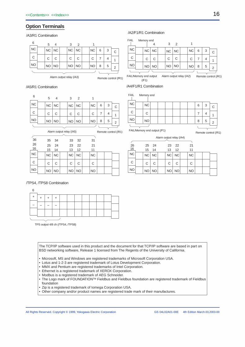
/A3/R1 Combination/A2/F1/R1 Combination
/A5/R1 Combination /A4/F1/R1 Combination
123456
111213141516212223242526212223242526
313233343536
NC
C
NO
NC
C
NO
NC
C
NO
NC
C
NO
NC
C
NO
NC
C
NO
3
4
5
6
7
8
C
1
2
NC
C
NO
NC
C
NO
NC
C
NO
NC
C
NO
NC
C
NO
NC
C
NO
NC
C
NO
NC
C
NO
NC
C
NO
NC
C
NO
NC
C
NO
NC
C
NO
NC
C
NO
NC
C
NO
NC
C
NO
NC
C
NO
NC
C
NO
NC
C
NO
NC
C
NO
NC
C
NO
NC
C
NO
NC
C
NO
NC
C
NO
NC
C
NO
NC
C
NO
NC
C
NO
3
4
5
6
7
8
C
1
2
3
4
5
6
7
8
C
1
2
3
4
5
6
7
8
C
1
2
Alarm output relay (/A3) Remote control (/R1)
1234
Alarm output relay (/A2) Remote control (/R1)
Alarm output relay (/A4)
Remote control (/R1)
11121314
123456
1516
Alarm output relay (/A5) Remote control (/R1)
FAIL/Memory end output (/F1)
FAIL/Memory end output (/F1)
FAIL Memory end
FAIL Memory end
/TPS4, /TPS8 Combination
6
+
–
+
–
+
–
+
–
TPS output 4/8 ch (/TPS4, /TPS8)
Option Terminals
The TCP/IP software used in this product and the document for that TCP/IP software are based in part on BSD networking software, Release 1 licensed from The Regents of the University of California.
• Microsoft, MS and Windows are registered trademarks of Microsoft Corporation USA.• Lotus and 1-2-3 are registered trademark of Lotus Development Corporation.• MMX and Pentium are registered trademarks of Intel Corporation.• Ethernet is a registered trademark of XEROX Corporation.• Modbus is a registered trademark of AEG Schneider.• The Logo mark of FOUNDATIONTM Fieldbus and Fieldbus foundation are registered trademark of Fieldbus
foundation• Zip is a registered trademark of Iomega Corporation USA.• Other company and/or product names are registered trade mark of their manufactures.
4th Edition March.03,2003-00


![General Specifications - Yokogawacdn2.us.yokogawa.com/GS33K55R40-50E.pdf · General Specifications [Release 5] GENERAL ... Contact](https://img.dokumen.tips/doc/110x75/5aa604cc7f8b9a1d728deb53/general-specications-specications-contents-index-release-5-general-.jpg)


