Embed Size (px)
Citation preview

GEA Bock HG44e/HG56eAssembly instructions
96416-09.2019-Gb
Translation of the original instructions
HG44e/475-4 HG44e/475-4 S HGX44e/475-4 HGX44e/475-4 SHG44e/565-4 HG44e/565-4 S HGX44e/565-4 HGX44e/565-4 S HG44e/665-4 HG44e/665-4 S HGX44e/665-4 HGX44e/665-4 SHG44e/770-4 HG44e/770-4 S HGX44e/770-4 HGX44e/770-4 S
HG56e/850-4 HG56e/850-4 S HGX56e/850-4 HGX56e/850-4 SHG56e/995-4 HG56e/995-4 S HGX56e/995-4 HGX56e/995-4 S HG56e/1155-4 HG56e/1155-4 S HGX56e/1155-4 HGX56e/1155-4 S

2
D
GB
F
E
9641
6-09
.201
9-DG
bFEI
Ru
Contents Page
1 Safety 4 1.1 Identificationofsafetyinstructions 1.2 Qualificationsrequiredofpersonnel 1.3 Generalsafetyinstructions 1.4 Intendeduse 2 Product description 6 2.1 Shortdescription 2.2 Nameplate 2.3 Typekey
About these instructionsReadtheseinstructionsbeforeassemblyandbeforeusingthecompressor.Thiswillavoidmisunder-standings andpreventdamage.Improperassemblyanduseofthecompressorcanresultinseriousorfatalinjury.Observethesafetyinstructionscontainedintheseinstructions.Theseinstructionsmustbepassedontotheendcustomeralongwiththeunitinwhichthecompres-sorisinstalled.
GEABockGmbH
72636Frickenhausen
GEABockGmbH
Benzstraße7
72636Frickenhausen
Germany
Phone+49702294540
Fax+4970229454137
www.gea.com
Manufacturer
Contact

D
GB
F
E
3
9641
6-09
.201
9-DG
bFEI
Ru
Contents Page
3 Areas of application 8 3.1 Refrigerants 3.2 Oilcharge 3.3 Limitsofapplication 4 Compressor assembly 11 4.1 Storageandtransport 4.2 Settingup 4.3 Pipeconnections 4.4 Pipes 4.5 Layingsuctionanspressurelines 4.6 Operatingtheshut-offvalves 4.7 Operatingmodeofthelockableserviceconnections 4.8 Suctionpipefilter 5 Electrical connection 15 5.1 Informationforcontactorandmotorcontactorselection 5.2 Standardmotor,designfordirectorpartialwindingstart 5.3 Basiccircuitdiagramforpartialwindingstartwithstandardmotor 5.4 Specialmotor:designfordirectorstar-deltastart 5.5 Basiccircuitdiagramfor star-delta startwithspecialmotor 5.6 ElectronictriggerunitINT69G 5.7 ConnectingofthetriggerunitINT69G 5.8 FunctionaltestofthetriggerunitINT69G 5.9 Oilsumpheater(accessories) 6 Commissioning 25 6.1 Preparationsforstart-up 6.2 Pressureintegritytest 6.3 Leaktest 6.4 Evacuation 6.5 Refrigerantcharge 6.6 Start-up 6.7 Avoidslugging 6.8 Connectionofoillevelregulator 7 Maintenance 28 7.1 Preparation 7.2 Worktobecarriedout 7.3 Sparepartsrecommendation 7.4 Accessories 7.5 Extractfromthelubricantstable 7.6 Decommissioning 8 Accessories 30 8.1 Capacityregulator 9 Technical data 32 10 Dimensions and connections 34 11 Declaration of incorporation 36 12 Service 37

4
D
GB
F
E
9641
6-09
.201
9-DG
bFEI
Ru
1| Safety
1.2 Qualificationsrequiredofpersonnel
DANGER Indicates a dangerous situation which, if not avoided, will cause immediate fatal or serious injury.
WARNING Indicates a dangerous situation which, if not avoided, may cause fatal or serious injury.
CAUTION Indicates a dangerous situation which, if not avoided, may cause fairly severe or minor injury.
ATTENTION Indicates a situation which, if not avoided, may cause property damage.
INFO Important information or tips on simplifying work.
WARNING Inadequatelyqualifiedpersonnelposestheriskofaccidents,the consequencebeingseriousor fatal injury.Workoncompressorsisthereforereservedforpersonnelwhichisqualifiedtoworkonpressurized refrigerant systems:•For example, a refrigeration technician, refrigeration mechatronicengineer. As well as professions with comparable training, whichenables personnel to assemble, install, maintain and repair refrigerationandair-conditioningsystems.Personnelmustbecapableofassessingtheworktobecarriedoutandrecognisinganypotentialdangers.
1.1 Identificationofsafetyinstructions:

D
GB
F
E
5
9641
6-09
.201
9-DG
bFEI
Ru
1| Safety
1.4 Intended use
1.3 General safety instructions
WARNING Risk of accidents. Refrigerating compressors are pressurised machines and as such call for heightened caution and care in handling.
The maximum permissible overpressure must not be exceeded, even for testing purposes.
Risk of burns! - Depending on the operating conditions, surface temperatures of over 60°C on the discharge side or below 0°C on the suction side can be reached. - Avoid contact with refrigerant necessarily. Contact with refrigerant can cause severe burns and skin damage.
WARNING The compressor may not be used in potentially explosive environments!
Theseassemblyinstructionsdescribethestandardversionofthecompressornamedinthetitleman-ufacturedbyGEA. GEArefrigeratingcompressorsareintendedforinstallationinamachine(withintheEUaccordingtotheEUDirectives2006/42/ECMachineryDirective,2014/68/EUPressureEquipmentDirective).Commissioningispermissibleonlyifthecompressorhasbeeninstalledinaccordancewiththeseas-semblyinstructionsandtheentiresystemintowhichitisintegratedhasbeeninspectedandapprovedinaccordancewithlegalregulations.
Thecompressorsareintendedforuseinrefrigerationsystemsincompliancewiththelimitsofapplication.
Onlytherefrigerantspecifiedintheseinstructionsmaybeused.
Any other use of the compressor is prohibited!
6
D
GB
F
E
9641
6-09
.201
9-DG
bFEI
Ru
• HG44e:Semi-hermeticfour-cylinderreciprocatingcompressorwithsuction-gascooleddrivemotor.• HG56e:Semi-hermeticsix-cylinderreciprocatingcompressorwithsuction-gascooleddrivemotor.• Preferredapplicationrange:normalrefrigeratingandair-conditioning.
2 | Product description
Nameplate
Fig.1
2.1 Short description
Valveplate Cylindercover
DimensionandconnectionvaluescanbefoundinChapter10
Transporteyelet
Dischargeshut-offvalve
Oilpump
Suction shut-offvalve
Oilsightglass
Drivesection
Motorsection
Fig.2
HG44e
HG56e
Terminalbox

D
GB
F
E
7
9641
6-09
.201
9-DG
bFEI
Ru
1 Typedesignation 6 Voltage,circuit,frequency2 Machinenumber 7 Nominalrotationspeed3 maximumoperatingcurrent 8 Displacement4 Startingcurrent(rotorblocked) 9 Voltage,circuit,frequency Y:Partwinding1 10 Nominalrotationspeed YY:Partwindings1and2 11 Displacement5 ND(LP):max.admissibleoperatingpressure 12 Oiltypefilledatthefactory (g)Lowpressureside 13 Terminalboxprotectiontype HD(HP):max.admissibleoperating Electrical accessories can change pressure(g)Highpressureside the IP protection class! Observe the limits of application diagrams!
50 Hz}
60 Hz}
2 | Product description
Fig.3
2.2 Name plate (example)
12345
6789
10111213
BB12345A001HGX44e/770-4 S
35,0 A101 A 174 A
67,0
80,4SE 55
GEA Bock GmbH72636 Frickenhausen, Germany
/HG 44 e 770- 4 SX
¹)HG-HermeticGas-Cooled(suctiongas-cooled)
²)X - Esteroilcharge(HFCrefrigerant,e.g. R134a,R404A/R507,R407C,R407F)3)S - Morepowerfulmotor,e.g.forair-conditioningapplications
Motorvariant3)
Numberofpoles
Sweptvolume
e-series(optimizedefficiency)
Numbersofcylinders
Size
Oilcharge²)
Series¹)
2.3 Type key (example)
8
D
GB
F
E
9641
6-09
.201
9-DG
bFEI
Ru
ATTENTION The oil level must be in the visible part of the sight glass; damage to the compressor is possible if overfilled or underfilled!
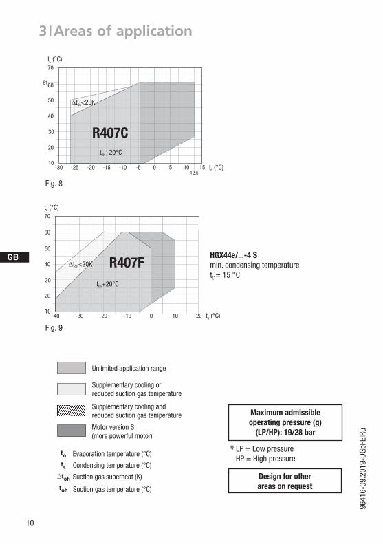
3 | Areas of application
Thecompressorsarefilledatthefactorywiththefollowingoiltype:-fürR134a,R404A/R507,R407C,R407F FUCHSRenisoTritonSE55 -fürR22 FUCHSRenisoSP46Compressorswithesteroilcharge(FUCHSRenisoTritonSE55)aremarkedwithanXinthetypedesignation(e.g.HGX44e/770-4).
3.1 Refrigerants• HFKW/HFC: R134a,R404A/R507,R407C,R407F• (H)FCKW/(H)CFC: R22
3.2 Oil charge
INFO For refilling, we recommend the above oil types. Alternatives: see lubricants table, Chapter 7.5
ATTENTION Compressor operation is possible within the operating limits showninthediagrams.Pleasenotethesignificanceoftheshaded areas. Thresholds should not be selected as design or continuous operation points.
- Permissible ambient temperature (-20°C) - (+60°C)- Max. permissible discharge end temperature 140°C.-Max.permissibleswitchingfrequency12x/h.- A minimum running time of 3 min. steady-state condition (continuous operation) must be achieved.
For operation with supplementary cooling:- Use only oils with high thermal stability.- Avoid continuous operation near the threshold.
For operation with capacity regulator:- Continuous operation, when the capacity regulator is activated,
is not permissible and can cause damage to the compressor.- The suction gas superheat temperature may need to be reduced
or set individually when operating near to the threshold.- When the capacity regulator is activated, the gas velocity in the systemcannotundercertaincircumstancesensurethatsuffi-cient oil is transported back to the compressor.
Foroperationwithfrequencyconverter:- The maximum current and power consumption must not be exceeded.Inthecaseofoperationabovethemainsfrequency,theapplication limit can therefore be limited.
3.3 Limits of application
max.
min.
oillevel
Fig.4Fig.4
HG44e1,6Ltr.HG56e1,4Ltr.
~~
~~

D
GB
F
E
9
9641
6-09
.201
9-DG
bFEI
Ru
3 | Areas of application
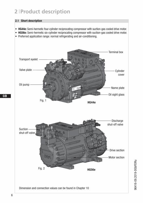
Fig.5
Fig.6
Fig.7
ATTENTION When operating in the vacuum range, there is a danger of air entering on the suction side. This can cause chemical reactions, a pressure rise in the condenser and an elevated compressed-gas temperature. Prevent the ingress of air at all costs!
Unlimitedapplicationrange
Supplementarycoolingorreducedsuctiongastemperature
Supplementarycoolingandreducedsuctiongastemperature
MotorversionS(morepowerfulmotor)
Evaporationtemperature(°C)
Condensingtemperature(°C)
Suctiongassuperheat(K)
Suctiongastemperature(°C)
Design for other areasonrequest
Maximum admissible operating pressure (g)
(LP/HP): 19/28 bar
1) LP=LowpressureHP=Highpressure
20
30
50
70
80
-20 -10 100 20 30 t (°C)o
t (°C)c
82
-30
40
60
12,5 25
t +20°COh
90
?tOh<20K
10
R134a
-50 -30-40 -20 10 t (°C)o07,5-45
20
40
50
t (°C)c
10
30
6058
?tOh<20K
-10
t +20°COh
R404A/R507
20100-10-20-30-4020
30
40
50
60
70
t (°C)o
t (°C)c
66
-35
t +20°Coh
-5 12,5
?toh<20KR22
10
D
GB
F
E
9641
6-09
.201
9-DG
bFEI
Ru
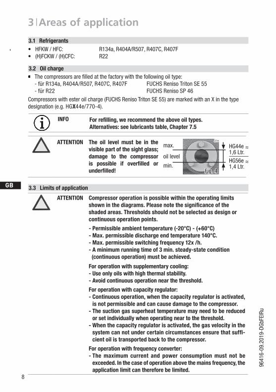
Fig.8
Fig.9
3 | Areas of application
Unlimitedapplicationrange
Supplementarycoolingorreducedsuctiongastemperature
Supplementarycoolingandreducedsuctiongastemperature
MotorversionS(morepowerfulmotor)
Evaporationtemperature(°C)
Condensingtemperature(°C)
Suctiongassuperheat(K)
Suctiongastemperature(°C)
Design for other areasonrequest
Maximum admissible operating pressure (g)
(LP/HP): 19/28 bar
1) LP=LowpressureHP=Highpressure
61
10
30
50
60
-30 -25 -10-15 0 15 t (°C)o
t (°C)c
20
40
t +20°COh
70
5-20 10-512,5
?tOh<20K
R407C
10
30
50
60
-40 -30 -10-20 0 20 t (°C)o
t (°C)c
20
40
t +20°COh
70
?tOh<20K
10
R407FHGX44e/...-4 Smin.condensingtemperaturetC =15°C

D
GB
F
E
11
9641
6-09
.201
9-DG
bFEI
Ru
Sunprotection:Ifthecompressorissetupoutdoors,ithas tobeprotectedfromdirectsunlight.
4 | Compressor assembly
INFO Newcompressorsarefactory-filledwithinertgas.Leavethisser-vice charge in the compressor for as long as possible and prevent the ingress of air. Check the compressor for transport damage before starting any work.
ATTENTION Attachments (e.g. pipe holders, additional units, fastening parts, etc.) directly to the compressor are not permissible!
Setuponanevensurfaceorframewithsufficientload-bearingcapacity.
Singlecompressorpreferablyonvibrationdamper. Duplexandparallelcircuitsalwaysrigid.
Provideadequateclearanceformaintenancework. Ensureadequatecompressorventilation.
Donotuseinacorrosive,dusty,dampatmosphereoracombustibleenvironment.
F
E
D
C
B
A
1234
F
E
D
C
4 3 2 1
A
BTol.-Ang. DIN ISO 2768-mK
Ra Rz
Maß Passung Freigabe
Alternativbezug:Baumustergeprüft
Teil inaktiv
Lieferantenzeichnung
--
K.-Auftrag:PL:
Zeichnung ungültig
Entwicklungsstand
Teil keine Serie
120400
±0.5
über 0.5bis 6
Benzstraße 7 - 72636 Frickenhausen - Germany - www.bock.de
-
-Unbemaßte Radien:
-
Diese Zeichnung ist unser Eigentum!Sie darf ohne unsere Genehmigung weder nach-gebildet, vervielfältigt, oder Dritten Personen zu-gänglich gemacht werden. Der Nachbau nachdieser Zeichnung, oder an Hand der nach dieserZeichnung hergestellten Gegenstände durch denAbnehmer oder Dritte ist nicht gestattet.Wir behalten uns alle Rechte, gemäß DIN ISO 16016an dieser Zeichnung vor.
Bearb.DatumÄnderungs-Nr.
Werkstoff:
Ausgangsteil, bzw. Rohteil:-
-
Gepr.
NameDatum19.04.
WerkstückkantenDIN ISO 13715
Ersatz für:
Ersetzt durch:
Erstellt2010
Geprüft
-
Kurz
Zone
1/x
Oberflächenbehandlung / Härte:-
Blatt:Änderungsbeschreibung
400Benennung:
±0.8
1000 30 6
-
±0.3
12030
±0.2
Zeichn.-Nr. Teile-Nr.
Oberflächenangaben ISO 1302
x.xxxx-xxxxx.x
Zust.Gußtoleranzen:
Gewicht: (kg)
±0.1
Maßstab:
1:1
Wasserwaagefür Indesign
Der Lieferant muß sicherstellen, dass die Ware ineinwandfreiem Zustand angeliefert wird (Korrosions-schutz, Verpackung für sicheren Transport).
Rz 25Rz 160
s
25
zyxwut
0,05 Rz 1,60,30,71,62 Rz 166,3 Rz 63 Rz 6,3Rz 12,5
F:\u
ser\k
urz\
3D S
ache
n\3D
Tei
le\Z
eich
nung
en\W
asse
rwaa
ge
4.2 Setting up
?4.1 Storage and transport
Usetransporteyelet. Donotliftmanually! Useliftinggear!
Storageat(-30°C)-(+70°C),maximumpermissiblerelativehumidity10%-95%,nocondensation
Donotstoreinacorrosive,dusty,vaporousatmosphereorinacom-bustibleenvironment.

12
D
GB
F
E
9641
6-09
.201
9-DG
bFEI
Ru
4.4 Pipes
Pipesandsystemcomponentsmustbecleananddryinsideandfreeofscale,swarfandlayersofrustandphosphate.Onlyuseair-tightparts.
Lay pipes correctly. Suitable vibration compensatorsmust be provided to prevent pipes being crackedandbrokenbyseverevibrations.
Ensureaproperoilreturn. Keeppressurelossestoanabsoluteminimum.
The pipe connectionshavegraduatedinsidediameterssothatpipeswithstandartmillimetreandinchdimensionscanbeused.Theconnectiondiametersoftheshut-offvalvesareratedformaximumcompressoroutput.Theactualrequiredpipecrosssectionmustbematched to the output. The same applies for non-return valves.
Fig.10:graduatedinternaldiameter
4.3 Pipe connections
ATTENTION Damage possible.Superheating can damage the valve. Remove the pipe supports from the valve for soldering. Only solder using inert gas to inhibit oxidation products (scale).
4 | Compressor assembly
4.5 Laying suction and pressure lines
ATTENTION Improperly installed pipes can cause cracks and tears, the result being a loss of refrigerant.
INFO Proper layout of the suction and discharge lines directly after the compressor is integral to the system’s smooth running and vibration behaviour.

D
GB
F
E
13
9641
6-09
.201
9-DG
bFEI
Ru
Fig.11
As short as possible
Rigid fixed point
4 | Compressor assembly
A rule of thumb: Alwayslaythefirstpipesectionstartingfromtheshut-offvalvedownwards and parallel to the drive shaft.
a)ForHG44eaintermediateflange(height27mm)isoptionalavailable, Art-Nr.81194. Withthisintermediateflangeitispossibletolaythepressurelinedirectlyfrom
thevalvetotheleftorright.
a)
4.6 Operating the shut-off valves Beforeopeningorclosingtheshut-offvalve,releasethevalvespindlesealbyapprox.¼ofaturncounter-clockwise.
Afteractivatingtheshut-offvalve,re-tightentheadjustablevalvespindlesealclockwise.
Fig.12 Fig.13
Valve spindle seal
Release Tighten

14
D
GB
F
E
9641
6-09
.201
9-DG
bFEI
Ru
4 | Compressor assembly
Pipeconnection
Pipeconnection
4.7 Operating mode of the lockable service connections
Fig.14Opening the shut-off valve:Spindle:turntotheleft(counter-clockwise)asfarasitwillgo.—>Shut-offvalvecompletelyopened/serviceconnectionclosed.Theconnectionwhichcannotbeshutoffisintendedforsafetydevices.
Fig.15Opening the service connectionSpindle:Turn½-1turntotherightclockwise.—>Serviceconnectionopened/shut-offvalveopened.Theconnectionwhichcannotbeshutoffisintendedforsafetydevices.
Serviceconnectionclosed
Connectionblocked
Spindle
Connectioncannot beshutoff
Connectioncannot beshutoff
Serviceconnectionopened
SpindleConnectionopen
Compressor
Compressor
Afteractivatingthespindle,generallyfitthespindleprotectioncapagainandtightenwith14-16Nm.Thisservesasasecondsealingfeatureduringoperation.
For systems with long pipes and higher degree of contamination, a filter on the suction-side is recommended.Thefilterhastobebereneweddependingonthedegreeofcontamination(reducedpressureloss).
4.8Suctionpipefilter

D
GB
F
E
15
9641
6-09
.201
9-DG
bFEI
Ru
Designationonthenameplate Stickerontheterminalbox
Y/YY
Compressorswiththismarkingaresuitablefordirectorpartialwindingstart.Themotorwindingissubdividedintotwoparts:Part winding 1 = 50% and part winding 2 = 50%.Thiswindingdivisionreducesthestart-upcurrentneededforapartwindingstarttoapprox.50%ofthatforadirectstart.
INFO A mechanical unloaded start with bypass solenoid valve is notrequired.
5| Electrical connection
5.1 Information for contactor and motor contactor selectionAllprotectionequipment,switchingandmonitoringdevicesmustcomplywiththelocalsafetyregula-tionsandestablishedspecifications(e.g.VDE)andregulationsaswellasthemanufacturer’sspeci-fications.Motorprotectionswitchesarerequired!Motorcontactors,feedlines,fusesandmotorprotectionswitchesmustberatedaccording to themaximumoperatingcurrent (seenameplate). Formotorprotection,useacurrent-independent,time-delayedoverloadprotectiondeviceformonitor-ingallthreephases.Adjusttheoverloadprotectiondevicesothatitmustbeactuatedwithin2hoursat1.2timesthemaximumworkingcurrent.
INFO Connectthecompressormotorinaccordancewiththecircuitdiagram(seeinsideofterminalbox).Usesuitablecableentrypointofthecorrectprotectiontype(see nameplate)forroutingcablesintotheterminalbox.Insertthestrain reliefsandpreventchafemarksonthecables.Comparethevoltageandfrequencyvalueswiththedataforthe mainspowersupply.Only connect the motor if these values are the same.
DANGER Risk of electric shock! High voltage! Only carry out work when the electrical system is disconnected from the power supply!
5 Electrical connection
ATTENTION When attaching accessories with an electrical cable, a minimum bending radius of 3 x the cable diameter must be maintained for laying the cable.
5.2 Standard motor, design for direct or part winding start

16
D
GB
F
E
9641
6-09
.201
9-DG
bFEI
Ru
Fig.16
Οnderung
0
Datum Name
Datum
Bearb.
Gepr.
Norm
1
20.02.2009
bauknecht
04.08.2017
Urspr.
2
Ers. f.
3
Ers. d.
4
PW INT69 HG44/66
5 6 7
BOCK COMPRESSORS
8
=
+
9
Bl.
6.c Bl.
6.a
2
Anschlußkasten Verdichter
BT1
INT69
DELTA- P II
QA1
L1 L2 L3 N PE
FC1.1
I> I>I>
QA2
1U1
1V1
1W1
PE
EC1
MY/YY
2U1
2V1
2W1
FC1.2
I> I>I>
QA3FC1.1
FC1.2
FC2
SF1
BP2
P>
QA2
BP3
P
QA2
KF1
KF1
6.c.8
QA2
L1.1L2.1L3.1L1.2
NPE
QA3
BT3
BT2Θ
1112 14L N B1 B2
121110987654321
Θ
vio bn bu gr
Θ
EB1
pk og
50% 50%
Compressorterminalbox
5.3 Basic circuit diagram for part winding start with standard motor
BP2 HighpressuresafetymonitorBP3 Safetychain(high/lowpressuremonitoring)BT1 Coldconductor(PTCsensor)motorwindingBT2 Thermalprotectionthermostat (PTCsensor)BT3 Releaseswitch(thermostat)DELTA-P II OildifferentialpressuresensorDELTA-PII(accessorie)EB1 OilsumpheaterEC1 Compressormotor

D
GB
F
E
17
9641
6-09
.201
9-DG
bFEI
Ru
Οnderung
0
Datum Name
Datum
Bearb.
Gepr.
Norm
1
20.02.2009
bauknecht
04.08.2017
Urspr.
2
Ers. f.
3
Ers. d.
4
PW INT69 HG44/66
5 6 7
BOCK COMPRESSORS
8
=
+
9
Bl.
6.c Bl.
6.a
2
Anschlußkasten Verdichter
BT1
INT69
DELTA- P II
QA1
L1 L2 L3 N PE
FC1.1
I> I>I>
QA2
1U1
1V1
1W1
PE
EC1
MY/YY
2U1
2V1
2W1
FC1.2
I> I>I>
QA3FC1.1
FC1.2
FC2
SF1
BP2
P>
QA2
BP3
P
QA2
KF1
KF1
6.c.8
QA2
L1.1L2.1L3.1L1.2
NPE
QA3
BT3
BT2Θ
1112 14L N B1 B2
121110987654321
Θ
vio bn bu gr
Θ
EB1
pk og
FC1.1/1.2 MotorprotectionswitchFC2 ControlpowercircuitfuseINT69G ElectronictriggerunitINT69GKF1 DelayrelayforcontactorswitchoverQA1 MainswitchQA2 Mainscontactor(partwinding1)QA3 Mainscontactor(partwinding2)SF1 Controlvoltageswitch

18
D
GB
F
E
9641
6-09
.201
9-DG
bFEI
Ru
5| Electrical connection
400 V
Direktstart YY Teilwicklungsstart Y/YY
1V1 1W11U1
2W12V12U1
L3L2L1 L3L2L1
L3L2L1
1V1 1W11U1
2W12V12U1
Direct start YY Part winding start Y/YY
Themotoriswiredfordirectstart(YY)atthefactory.ForpartwindingstartY/YY,thebridgesmustberemovedandthemotorfeedlineconnectedaccordingtothecircuitdiagram:
ATTENTION Failure to do this results in opposed rotary fields and results indamage to the motor. After the motor starts up via partial winding 1, partial winding 2 must be switched on after a maximum delay of one second . Failure to comply can adversely affect the service life of the motor.

D
GB
F
E
19
9641
6-09
.201
9-DG
bFEI
Ru
5| Electrical connection
5.4 Special motor: design for direct or star-delta start
Amechanicalunloadedstartwithbypasssolenoidvalveisrequiredforthestar-deltastart.
Designationonthenameplate Stickerontheterminalbox
∆ / Y
Star-delta start-up is only possible for 230 V power supply. Example:
230 V ∆
Direct start Star-delta start
400 V Y
Direct start only
5.4 Sondermotor: Ausführung für Direkt- oder Stern-Dreieck-Anlauf
Für den Stern-Dreieck-Anlauf ist eine mechanische Anlaufentlastung mit Bypass-Magnetventil (Zubehör) erforderlich.
Bezeichnung auf dem Typschild Aufkleber auf Klemmenkasten
∆ / Y
Stern-Dreieck-Anlauf ist nur im Spannungsbereich ∆ (230 V) möglich. Beispiel:
230 V ∆
Direktstart Stern-Dreieck-Start
L3L1
V1 W1U1
V2U2W2
L1 L2 L3
L2
V1 W1U1
V2U2W2
L3L2L1
400 V Y
nur Direktstart
V1 W1U1
V2U2W2
L1 L2 L3

20
D
GB
F
E
9641
6-09
.201
9-DG
bFEI
Ru
Οnderung
2
0
Datum Name
Datum
Bearb.
Gepr.
Norm
1
20.02.2009
bauknecht
04.08.2017
Urspr.
2
Ers. f.
3
Ers. d.
4
D/S INT69 HG44/66 neu
5 6 7
BOCK COMPRESSORS
8
=
+
9
Bl.
6.c Bl.
6.b
6.a
Anschlußkasten Verdichter
BT1
INT69G
DELTA- P II
QA1
L1 L2 L3 N PE
1U1
1V1
1W1
PE
2U1
2V1
2W1
FC1.1
FC1.2
FC2
SF1
BP2
P>
BP3
P
QA2
L1.1L2.1L3.1L1.2
NPE
BT3
BT2Θ
1112 14L N B1 B2
121110987654321
Θ
vio bn bu gr pk og
Θ
1 2PE
EB1
FC1.1
I> I>I>
1
2
QA2
FC1.2
I> I>I>
3
4
5
6
1
2
QA4Y
3
4
5
6
1
2
QA3D
3
4
5
6
EC1
M3 ˜
QA2
QA2
6.b.7
QA4 KF1QA4
QA3
6.b.8
KF1QA3
QA4
6.b.8
KF1
Fig.17
5.5 Basic circuit diagram for star-delta start with special motor
Compressorterminalbox
BP2 HighpressuresafetymonitorBP3 Safetychain(high/lowpressuremonitoring)BT1 Coldconductor(PTCsensor)motorwindingBT2 Thermalprotectionthermostat (PTCsensor)BT3 Releaseswitch(thermostat)DELTA PII OildifferentialpressuresensorDELTA-PII(accessorie)EB1 OilsumpheaterEC1 CompressormotorFC1.1/1.2 Motorprotectionswitch

D
GB
F
E
21
9641
6-09
.201
9-DG
bFEI
Ru
Οnderung
2
0
Datum Name
Datum
Bearb.
Gepr.
Norm
1
20.02.2009
bauknecht
04.08.2017
Urspr.
2
Ers. f.
3
Ers. d.
4
D/S INT69 HG44/66 neu
5 6 7
BOCK COMPRESSORS
8
=
+
9
Bl.
6.c Bl.
6.b
6.a
Anschlußkasten Verdichter
BT1
INT69G
DELTA- P II
QA1
L1 L2 L3 N PE
1U1
1V1
1W1
PE
2U1
2V1
2W1
FC1.1
FC1.2
FC2
SF1
BP2
P>
BP3
P
QA2
L1.1L2.1L3.1L1.2
NPE
BT3
BT2Θ
1112 14L N B1 B2
121110987654321
Θ
vio bn bu gr pk og
Θ
1 2PE
EB1
FC1.1
I> I>I>
1
2
QA2
FC1.2
I> I>I>
3
4
5
6
1
2
QA4Y
3
4
5
6
1
2
QA3D
3
4
5
6
EC1
M3 ˜
QA2
QA2
6.b.7
QA4 KF1QA4
QA3
6.b.8
KF1QA3
QA4
6.b.8
KF1
FC2 ControlpowercircuitfuseINT69G ElectronictriggerunitINT69GKF1 DelayrelayforcontactorswitchoverQA1 MainswitchQA2 MainscontactorQA3 Δ-contactorQA4 Y-contactorSF1 Controlvoltageswitch

22
D
GB
F
E
9641
6-09
.201
9-DG
bFEI
Ru
TerminalboxFig.18
ATTENTION Measure circuit BT1 and BT2 (PTC sensor) must not come into contact with external voltage. This would destroy the trigger unit INT69 G and PTC sensors.
5.6 Electronic trigger unit INT69 G
5.7 Connection of the trigger unit INT69 G
The compressormotor is fittedwith cold conductor temperature sensors (PTC) connected to theelectronic trigger unit INT69G in the terminal box. In case of excess temperature in themotorwinding,theINT69Gdeactivatesthemotorcontactor.Oncecooled,itcanberestartedonlyiftheelectroniclockoftheoutputrelay(terminalsB1+B2)isreleasedbyinterruptingthesupplyvoltage.
Thehotgassideof thecompressorcanalsobeprotectedagainstovertemperatureusing thermalprotectionthermostats(accessory).
The unit trips when an overload or inadmissible operating conditions occur. Find and remedy the cause.
INFO The relayswitchingoutput isexecutedasafloatingchangeover contact.Thiselectricalcircuitoperatesaccordingtothequiescent current principle, i.e. the relay drops into a the idle position and deactivates the motor contactor even in case of a sensor break or open circuit.
INFO Connect the trigger unit INT69 G in accordance with the circuit dia-gram. Protect the trigger unit with a delayed-action fuse (FC2) of max. 4 A. In order to guarantee the protection function, install the triggerunitasthefirstelementinthecontrolpowercircuit.
5| Electrical connection
Οnderung
Klebeschilder
0
Datum Name
Datum
Bearb.
Gepr.
Norm
1
04.12.2009
Kelich
22.05.2015
Urspr.
2
Ers. f.
3
Ers. d.
4
Schaltplan
5 6 7
BOCK COMPRESSORS
8
=
+
9
Bl.
MP10 INt69 Bl.
MP10 INt69
INT69 G Motor Protection MP10
Steuerstrom-
kreis
LN
Steuerstrom-
kreis
L N1112 14
B1 B2OG OG
+
-BT1
Θ
X1 L1 L1 N N 43 43 11 12 14L S M
X2 1 2 3 4 5 6
R1 R2
+
-BT1
Θ
+
-BT2
Θ
+
-BT2
ΘLN
Controlcircuit

D
GB
F
E
23
9641
6-09
.201
9-DG
bFEI
Ru
5| Electrical connection
RelaypositionINT69G
B2 12 14 11
Fig.19
5.8 Function test of the trigger unit INT69 G
Beforecommissioning,aftertroubleshootingormakingchangestothecontrolpowercircuit,checkthefunctionalityofthetriggerunit.Performthischeckusingacontinuitytesterorgauge.
Gauge state Relay position
Deactivatedstate 11-12
INT69Gswitch-on 11-14
RemovePTCconnector 11-12
InsertPTCconnector 11-12
Resetaftermainson 11-14

24
D
GB
F
E
9641
6-09
.201
9-DG
bFEI
Ru
5| Electrical connection
5.9 Oil sump heater (accessories)
Anschlussschema für ÖlsumpfheizungConnection diagramm for oil sump heater Plan de raccordement pour résistance de carter d‘huile
0998
3- 10
.01-D
GBF
DGBF
Whenthecompressorisatastandstill,refrigerantdiffusesintothelubricatingoilofthecompressorshousing,dependingonpressureandambienttemperature.Thisreducesthelubricatingcapacityoftheoil.Whenthecompressorstartsup,therefrigerantcontainedintheoilevaporatesoutthroughtthereductioninpressure.Theconsequencescanbefoamingandmigrationoftheoil,causingoilshocksundercertaincircumstances.
Operation:Theoilsumpheateroperateswhenthecompressorisatastandstill.Whenthecompres-sorstartsup,theoilsumpheaterswitchesoffagainautomatically.
Connection:Theoilsumpheatermustbeconnectedviaanauxiliarycontact(orparallelwiredauxili-arycontact)ofthecompressorcontactortoaseperateelectriccircuit.El.data:230V-1-50/60Hz,160W.
Fig.20
ATTENTION Connection to the current path of the safety control chain is not permitted.

D
GB
F
E
25
9641
6-09
.201
9-DG
bFEI
Ru
6 | Commissioning
6.1 Preparations for start-up
6.4 Evacuation
Firstevacuatethesystemandthenincludethe compressor in the evacuation process. Relievethecompressorpressure. Openthesuctionandpressurelineshut-offvalves. Evacuatethesuctionanddischargepressuresidesusingthevacuumpump. Attheendoftheevacuationprocess,thevacuumshouldbe<1.5mbarwhenthepumpisswitchedoff. Repeatthisprocessasoftenasisrequired.
Thecompressorhasundergonetrialsinthefactoryandallfunctionshavebeentested.Therearethereforenospecialrunning-ininstructions.
Check the compressor for transport damage!
6.3 Leak test
CarryouttheleaktestontherefrigeratingplantinaccordancewithEN378-2oracorrespondingsafetystandard,whilealwaysobservingthemaximumpermissibleoverpressureforthecompressor.
INFO To protect the compressor against inadmissible operating conditions, high pressure and low pressure pressostats are mandatory on the installation side.
DANGER Risk of bursting! The compressor must only be pressurised using nitrogen (N2). Never pressurise with oxygen or other gases!The maximum permissible overpressure of the compressor must not be exceeded at any time during the testing process (see name plate data)! Do not mix any refrigerant with the nitrogen as this could cause the ignition limit to shift into the critical range.
ATTENTION Do not start the compressor if it is under vacuum. Do not apply any voltage - even for test purposes (must only be operated with refrigerant).Undervacuum,thespark-overandcreepagecurrentdistancesofthe terminalboardconnectionboltsshorten;thiscanresultinwindingand terminalboarddamage.
6.2 Pressure integrity test
Thecompressorhasbeentestedinthefactoryforpressureintegrity.Ifhowevertheentiresystemistobesubjectedtoapressureintegritytest,thisshouldbecarriedoutinaccordancewithEN378-2oracorrespondingsafetystandardwithout the inclusion of the compressor.

26
D
GB
F
E
9641
6-09
.201
9-DG
bFEI
Ru
6| Commissioning
Makesurethatthesuctionandpressurelineshut-offvalvesareopen.
Withthecompressorswitchedoff,addtheliquidrefrigerantdirectlytothecondenserorreceiver,breakingthevacuum.
Iftherefrigerantneedstoppingupafterstartingthecompressor,itcanbetoppedupinvapourformonthesuctionside,or,takingsuitableprecautions,alsoinliquidformattheinlettotheevaporator.
6.5 Refrigerant charge
CAUTION Wear personal protective clothing such as goggles and protective gloves!
ATTENTION Avoidoverfillingthesystemwithrefrigerant! To avoid shifts in concentration, zeotropic refrigerant blends must alwaysonlybefilledinto therefrigeratingplantinliquidform. Donotpourliquidcoolantthroughthesuctionlinevalveon
the compressor. It is not permissible to mix additives with the oil and
refrigerant.
6.6 Start-up
Checkthatthesafetyandprotectiondevices(pressureswitch,motorprotection,electricalcontactprotectionmeasures,etc.)areallfunctioningproperly.
Switchonthecompressorandallowtorunforaminimumof10min. Check the oil level by:Theoilmustbevisibleinthesightglass.
WARNING Ensure that both shut-off valves are open before starting the compressor!
ATTENTION Iflargerquantitiesofoilhavetobetoppedup,thereisariskofoil hammer effects. If this is the case check the oil return!

D
GB
F
E
27
9641
6-09
.201
9-DG
bFEI
Ru
6.8 Connection of oil level regulator
Oillevelregulationsystemshaveproventhemselveswithparallelcircuitsofseveralcompressors.Theconnection"0"isprovidedforinstallinganoillevelregulator(seedimensionsdrawing).AllcommonoillevelregulatorsfromAC&R,ESKandCarlyaswellastheOM3TraxOiloillevelregulationsystemfromAlcocanbeconnecteddirectlywithoutadapters(seeFig.21).Asightglassontheoillevelregulatorisnotrequired.
6| Commissioning
6.7 Avoiding slugging
To prevent slugging: Thecompleterefrigerationsystemmustbeproperlydesigned. Allcomponentsmustbecompatiblyratedwitheachotherwithregardtooutput (particularlytheevaporatorandexpansionvalves).
Suctiongassuperheatatthecompressorinputshould be min. 7 - 10 K.(checkthesetting oftheexpansionvalve).
Thesystemmustreachastateofequilibrium. Particularlyincriticalsystems(e.g.severalevaporatorpoints),measuresarerecommendedsuchasreplacementofliquidtraps,solenoidvalveintheliquidline,etc. There should be no movement of coolant whatsoever while the compressor is at a standstill.
ATTENTION Slugging can damage the compressor and cause refrigerant to leak.
Mechanicaloillevelregulatoratthe"O"connection
Fig.21
Schmierung / Ölkontrolle Bei Inbetriebnahme Öldruckkontrolle mittels Manometer über
den Schraderanschluss an der Ölpumpe vornehmen. Nach Erreichen des Beharrungszustands (kontinuierliche
Betriebsbedingung) Ölstand des Verdichters kontrollieren. Er soll im Schauglasbereich sichtbar sein (siehe Bild).
Automatische Überwachung durch Öldifferenzdruckschalter. Bei Inbetriebnahme Funktionsprüfung des Öldifferenzdruck-schalters vornehmen.
Bei Abschaltung durch das Gerät ist eine Störanalyse vorzunehmen.Hinweise auf dem Deckel des Schalters beachten.WARNUNG! Wenn größere Ölmengen nachgefüllt werden müssen, besteht die Gefahr von Ölschlägen. In diesem Falle muss die Ölrückführung überprüft werden.
i
Anschluss ÖlspiegelregulatorBei Verbundschaltungen von mehreren Verdichtern haben sich Ölstandsregulierungssysteme bewährt. Für die Montage eines Ölspie-gelregulators ist der Anschluss „O“ vorgesehen (siehe Maßzeichnung). Alle gängigen Ölspiegelregulatoren von AC&R, ESK sowie das elek-tronische Reglersystem TRAXOIL S1A1 von SPORLAN können direkt ohne Adapter angeschlossen werden (s. Abb.). Ein Schauglas am Ölspiegelregulator ist nicht erforderlich.
124 o
124o
124 o
124o
47,6
M6 x 10je 3 mal
3-Loch-Anschlussbild für ESK, AC&R und CARLY3-Loch-Anschlussbild für TraxOil
3holeconnectiondiagrammforESK,AC&RandCARLY3holediagrammforTraxOil
3timeseach

28
D
GB
F
E
9641
6-09
.201
9-DG
bFEI
Ru
7.3 Spare part recommendation
HG44e / ... 475-4(S) 565-4(S) 665-4(S) 770-4(S)
Designation Item No. Item No. Item No. Item No.
Setofgasketskit 81598
Valveplatekit 80965 80966
Oilpumpkit 80950
Oilsumpheaterkit230V~
81252
Only use genuine GEA spare parts!
HG56e / ... 850-4(S) 995-4(S) 1155-4(S)
Designation Item No. Item No. Item No.
Setofgasketskit 81599
Valveplatekit 80965 80966
Oilpumpkit 80950
Oilsumpheaterkit230V~
81252
7.1 Preparation
7| Maintenance
7.2 Work to be carried out
In order to guarantee optimum operational reliability and service life of the compressor, we recommend carryingoutservicingandinspectionworkatregularintervals: Oil change: - notmandatoryforfactory-producedseriessystems. - forfieldinstallationsorwhenoperatingneartheapplicationlimit:forthefirsttimeafter100
to 200 operating hours, then approx. every 3 years or 10,000 - 12,000 operating hours.Disposeofusedoilaccordingtotheregulations;observenationalregulations.
Annual checks: Oil level, leak tightness, running noises, pressures, temperatures, function ofauxiliarydevicessuchasoilsumpheater,pressureswitch.
WARNING Before starting any work on the compressor: Switch off the compressor and secure it to prevent a restart. Relieve compressor of system pressure. Preventairfrominfiltratingthesystem!
After maintenance has been performed: Connect safety switch. Evacuate compressor. Release switch lock.

D
GB
F
E
29
9641
6-09
.201
9-DG
bFEI
Ru
AvailableaccessoriescanbefoundontheInternetatwww.gea.com
7.4 Accessories
7 | Maintenance
7.6 Decommissioning
Closetheshut-offvalvesonthecompressor.Draintherefrigerant(itmustnotbedischargedintotheenvironment)anddisposeofitaccordingtotheregulations.Whenthecompressorisdepressurised,undothefasteningscrewsoftheshut-offvalves.Removethecompressorusinganappropriatehoist.Disposeoftheoilinsideinaccordancewiththeapplicablenationalregulations.
7.5 Extract from the lubricants table
Theoiltypefilledasstandardinthefactoryismarkedonthename plate. This oil type should be used as a preference.Alternativesarestatedintheextractfromourlubricantstablebelow.
Refrigerants GEA standard oil types Recommendedalternatives
HFKW(e.g.R134a,R407C)
Fuchs Reniso Triton SE 55
FuchsRenisoTritonSEZ32Esso/MobilEALArctic46SunocoSunisoSL46TexacoCapellaHFC55
HFCKW(e.g.R22) Fuchs Reniso SP 46
FuchsRenisoSP32BPEnergolLPT46SunocoSuniso3,5GSTexacoCapellaWF46

30
D
GB
F
E
9641
6-09
.201
9-DG
bFEI
Ru
8.1 Capacity regulator
Fig.22
CR 1
CR 2
ATTENTION Ifthecapacityregulatorisinstalledatthefactory,itissubsequentlyinstalled and connected by the customer.
8| Accessories
CR 1
Deliverycondition1(fromthefactory):Cylindercoverpreparedforcapacityregulator.
Fig.24
Before commissioning, the blind flange withscrewsmustberemovedandreplacedbythenew set capacity regulator with O-ring jointsandscrews.Observepositionandconstructionofthecapacityregulator.Attention! Compressor is under pressure!Depressurize the compressor first.
Deliverycondition2(fromthefactory):Connectcapacityregulatorinterminalboxorswitchcabinet.
Fig.23
Fig.25
HG44e HG56e

D
GB
F
E
31
9641
6-09
.201
9-DG
bFEI
Ru
Specialaccessoriesareonlypremountedinthefactoryiforderedspeciallybycustomer.Retrofittingispossibleinfullcompliancewiththesafetyinstructionsandrepairinstructionsenclosedwiththekits.Informationabouttheuse,operation,maintenanceandservicingofthecomponentsisavailableintheprintedliteratureorontheinternetunderwww.gea.com.
8| Accessories
ATTENTION Capacity-regulated operation alters the gas speeds and pressure ratios of the refrigerating plant: Adjust the suction line routing and
dimensioning accordingly, do not set the control intervals too close and do not let the system switch more than 12 times per hour(refrigeratingplantmusthavereachedastateofequilibrium).Continuous operation in the control stage is not recommended as the gas velocity in the plant system under certain circumstances doesnotguaranteesufficientoilreturntothecompressorwithactivated capacity regulator.
We recommend switching to unregulated operation (100% capac-ity) for at least 5 minutes per capacity-regulated operating hour.An assured oil return can also be realised by a 100% capacity requirementaftereachcompressorrestart.
Electrical actuation of the solenoid valve: Normally open, (cor-responds to 100 % compressor capacity).
WARNING Several capacity regulators cannot switch at the same time duringcompressor operation! Otherwise the sudden change in load can damage the compressor! Comply with the switching interval of 60 s.
• Complywiththeswitchingsequence: Swichingon LR1 60s LR2
Swichingoff LR2 60s LR1
Fig.26
Forthecapacityregulatorastepprotectionisoptionalavailable,Art-Nr.81449.

32
D
GB
F
E
9641
6-09
.201
9-DG
bFEI
Ru
Type
No. of cylinders
Displacement(1450 / 1740 rpm)
Elec
tric
al d
ata
Weight
Conn
ectio
ns
Oil charge (ex works)
Oil charge (sight glass centre)
Voltage
Max. operating current
Max. power consumption
Starting current(rotor locked)
Discharge line DV
Suction line SV
50 /
60 H
z P
W 1
+2
PW 1
/ PW
1+
2
m3 /h
VA
kWA
kgmm(inc
h)mm(inc
h)ltr
ltr
HG44
e/47
5-4
4
41.3/49
.6
380-420VY/YY-3-50HzPW440-480VY/YY-3-60HzPWPW=PartWindingWindingratio:50%/50%
1911,0
65/10
916
5
28(1
1/ 8)
35(1
3/ 8)
2.7
2.3
HG44
e/47
5-4S
41.3/49
.623
13,1
87/14
917
0
HG44
e/56
5-4
49.2/59
.022
13,2
65/10
916
6
HG44
e/56
5-4S
49.2/59
.026
15,6
101/1
7417
0
42(1
5/ 8)
HG44
e/66
5-4
57.7/69
.226
15,4
87/14
917
4
HG44
e/66
5-4S
57.7/69
.230
18,3
101/1
7417
1
HG44
e/77
0-4
67.0/80
.430
17,8
101/1
7417
1
HG44
e/77
0-4S
67.0/80
.435
21,4
101/1
7417
1
9| Technical data
12
3
2
4
Toleranc
e(±10%
)relativetoth
emea
nvalueofth
evolta
gera
nge.
Othe
rvoltage
san
dtype
sofcurrentonrequ
est.
-Th
especifica
tionsfo
rmax
.pow
ercon
sumptionap
plyfor5
0Hzop
eration.
Fo
r60H
zop
eration,th
especifica
tionshavetobemultip
liedbyth
efactor1.2.
Th
emax
.working
currentre
mainsunc
hang
ed.
- Take
accou
ntofthe
max.ope
ratin
gcu
rren
t/m
ax.p
owercon
sumptionfor
de
sign
offuses,sup
plylinesand
safetyde
vices.
Fu
se:C
onsumptioncatego
ryAC3
1 2
Allspe
cific
ationsarebased
ontheaverag
eofth
evolta
gera
nge
Fors
olde
rcon
nections
3 4

D
GB
F
E
33
9641
6-09
.201
9-DG
bFEI
Ru
Type
No. of cylinders
Displacement(1450 / 1740 rpm)
Elec
tric
al d
ata
Weight
Conn
ectio
ns
Oil charge (ex works)
Oil charge (sight glass centre)
Voltage
Max. operating current
Max. power consumption
Starting current(rotor locked)
Discharge line DV
Suction line SV
50 /
60 H
z P
W 1
+2
PW 1
/ PW
1+
2
m3 /h
VA
kWA
kgmm(inc
h)mm(inc
h)ltr
ltr
HG56
e/85
0-4
6
73.8/88
.6
380-420VY/YY-3-50HzPW440-480VY/YY-3-60HzPWPW=PartWindingWindingratio:50%/50%
3319
.710
1/1
7419
4
35(1
3/ 8)
54(2
1/ 8)
3.3
2.7
HG56
e/85
0-4S
73.8/88
.639
23.5
125/2
0921
1
HG56
e/99
5-4
86.6/10
3.9
3923
.212
5/2
0920
8
HG56
e/99
5-4S
86.6/10
3.9
4627
.714
9/2
4621
1
HG56
e/1155
-410
0.4/1
20.5
4728
.014
9/2
4621
2
HG56
e/1155
-4S
100.4/1
20.5
5833
.319
6/3
3522
1
9| Technical data
12
3
2
4
Toleranc
e(±10%
)relativetoth
emea
nvalueofth
evolta
gera
nge.
Othe
rvoltage
san
dtype
sofcurrentonrequ
est.
-Th
especifica
tionsfo
rmax
.pow
ercon
sumptionap
plyfor5
0Hzop
eration.
Fo
r60H
zop
eration,th
especifica
tionshavetobemultip
liedbyth
efactor1.2.
Th
emax
.working
currentre
mainsunc
hang
ed.
- Take
accou
ntofthe
max.ope
ratin
gcu
rren
t/m
ax.p
owercon
sumptionfor
de
sign
offuses,sup
plylinesand
safetyde
vices.
Fu
se:C
onsumptioncatego
ryAC3
1 2
Allspe
cific
ationsarebased
ontheaverag
eofth
evolta
gera
nge
Fors
olde
rcon
nections
3 4

34
D
GB
F
E
9641
6-09
.201
9-DG
bFEI
Ru
10| Dimensions and connections
HG44e
1) SV+DV90°rotatable
DimensionsinmmFig.27
Dimensionsin()=HG(X)44e/475-4(S) HG(X)44e/565-4
Centreofgravity
SVDV
SuctionlineDischargelineseetechnicladata,Chapte9
A Connectionsuctionside, notlockable 1/8“ NPTF
A1 Connectionsuctionside, lockable 7/16“ UNF
B Connectiondischargeside, notlockable 1/8“ NPTF
B1 Connectiondischargeside, lockable 7/16“ UNF
C Connectionoilpressureswitch 1/8“ NPTF
D ConnectionoilpressureswitchLP 7/16“ UNF
D1 Connectionoilreturnfromoilseparator 1/4“ NPTF
F Oildrain M12x1,5
H Oilchargeplug 1/4“ NPTF
J Connectionoilsumpheater 3/8“ NPTF
K Sightglass 3xM6
L Connectionthermalprotectionthermostat 1/8“ NPTF
M Oilstrainer M12x1,5
O Connectionoillevelregulator 3xM6
Q Connectionoiltemperaturesensor 1/8“ NPTF
W Connectionforrefrigerantinjection 1/8“ NPTF
Vibrationdamper
ViewHG(X)44e/475-4(S) HG(X)44e/565-4
1)
100 235
155
367 531 (509)
341
Maßstab /Part-No.
F
E
D
C
A
F
E
D
C
4 1
A
B
5678
12345678
Zeichn.-Nr. / Drawing no. :
B1.
Kunde / Customer:
2321
02
±0.1
über / above
Freigabe / Approved
zyxw
Der Lieferant muss sicherstellen, dass die Ware in einwandfreiem Zustand angeliefert wird (Korrosionsschutz, Verpackung für sicheren
A. Layh
Allgemeintoleranzen / General tolerances
Drawing-No.
bis / up to
Dok
-ID:
uts
-
0850
A. Layh
-
3 2
-in proper conditions (corrosion prevention, packaging for safe transportation).
DIN ISO 2768-mK-E
Ersatz für / replacement for:The supplier has to ensure the delivery of parts
Transport).
prohibited. Offenders will be held liable for the
Dimension model or design. Passung / Clearance
Baumustergeprüft / Type examination:
-K.-Auftrag / C.-Task:Projektleiter / Project leader:
120400±0.5
0.5
18.05.16
6
-
-
GEA Bock GmbH - Benzstraße 7 - 72636 Frickenhausen - Germany - www.bock.de
-
-
Bearb. / EditedDatum / Datepayment of damages. All rights reserved in the event
Änd.-Nr. / Mod-No.
-
Werkstoff (Zeile 2+3 alternativ) /
Base part, Raw part:
-
Geprüft / Appr.
Unbemaßte Radien / Undimensioned radii:
NameDatum / Date
Material (Line 2+3 alternative):
Ausgangsteil, Rohteil /
Workpiece edgesDIN ISO 13715
-
Erstellt / Drawn 18.05.16B. ZuderGeprüft / VerifiedS. Büttner
18.05.16
Werkstückkanten /
Page:
400Benennung / Description:
±0.81000
30 6
-
±0.312030
-
Blatt /
±0.2
of the grant of a patent, utility /
DIN EN ISO 1302
Zust. / Rev.
Gußtoleranzen / General casting tolerances:
Gewicht / Weight: (kg)
Zeichnungs-Nr. /
1/4
Indication of surface texture
Scale:
MC- HG44e/770-4 S
Rz 25Rz 160 Rz 1,6Rz 16Rz 63 Rz 6,3
Oberflächenbehandlung, Härte / Treatment of surface, Hardness:
Rz 12,5
%
Status:
-
-
Änderung nach Freigabe (CAD)
Nein / No 16161 .0
12.07.18
31.07.18
07.09.18
07.09.18
10.10.18
11.02.19
11.03.19
J. Faßbender
J. Faßbender
CAD Gast
CAD Gast
V. Polizzi
J. Faßbender
V. Polizzi
0f | Betrifft Blatt 3
0f | Betrifft Blatt 3
0g | Anschluss Öldruckmanometer "E" in Öldrucksicherheitsschalter "C" geändert.
0g | Betrifft Blatt 2+4
0g | Betrifft Blatt 2+4
0h | Aufnahme von 1/8" NPTF für Nacheinspritzung.
0i | Betrifft Blatt 3+4
10504
10415
10455
10433
10569
10686
10509
A. Layh
A. Layh
A. Layh
A. Layh
H. Christner
A. Layh
MK- HG44e/770-4 S
Weitergabe sowie Vervielfältigung dieses Dokuments, Verwertung und Mitteilung seines Inhalts sind ver-boten, soweit nicht ausdrücklich gestattet. Zuwider-handlungen verpflichten zu Schadenersatz. Alle Rechte für den Fall der Patent-, Gebrauchsmuster- oder Geschmacksmustereintragung vorbehalten.
The reproduction, distribution and utilization of this document as well as the communication of its contents to others without express authorization is
Maß
Oberflächenangaben /
Teile-Nr. /
A. Layh
Halbhermetischer Verdichter HG / Semi-hermetic compressor HG
1.0850-16161.0 0i
Anschlüsse /Connections
HG44e/ 475-4 (S)
565-4
HG44e/ 565-4 S
665-4 (S)770-4 (S)
SVSaugabsperrventil, Rohr (L)* mm - Zoll
35 - 1 3/8" 42 – 1 5/8"Suction line valve, tube (L)* mm - inch
DVDruckabsperrventil, Rohr (L)* mm - Zoll
28 - 1 1/8"Discharge line valve, tube (L)* mm - inch
AAnschluss Saugseite, nicht absperrbar
Zoll / inch 1/8" NPTFConnection suction side, not lockable
A1Anschluss Saugseite, absperrbar
Zoll / inch 7/16" UNFConnection suction side, lockable
BAnschluss Druckseite, nicht absperrbar
Zoll / inch 1/8" NPTFConnection discharge side, not lockable
B1Anschluss Druckseite, absperrbar
Zoll / inch 7/16" UNFConnection discharge side, lockable
CAnschluss Öldrucksicherheitsschalter
Zoll / inch 1/8" NPTFConnection oil pressure safety switch
DAnschluss Öldrucksicherheitsschalter LP
Zoll / inch 7/16" UNFConnection oil pressure safety switch LP
D1Anschluss Ölrückführung vom Ölabscheider
Zoll / inch 1/4" NPTFConnection oil return from oil separator
FÖlablass
mm M12x1,5Oil drain
HStopfen Ölfüllung
Zoll / inch 1/4" NPTFOil charge plug
JAnschluss Ölsumpfheizung
Zoll / inch 3/8" NPTFConnection oil sump heater
KSchauglas
mm 3xM6Sight glass
LAnschluss Wärmeschutzthermostat
Zoll / inch 1/8" NPTFConnection thermal protection thermostat
MÖlsieb
mm M12x1,5Oil filter
OAnschluss Ölspiegelregulator
mm 3xM6Connection oil level regulator
QAnschluss Öltemperatursensor
Zoll / inch 1/8" NPTFConnection oil temperature sensor
WAnschluss Kältemittel Einspritzung
Zoll / inch 1/8" NPTFConnection for refrigerant injection(L)* = Lötanschluss(L)* = Brazing connection
Maße in mmDimensions in mm
Änderungen vorbehaltenSubject to change without notice
MassenschwerpunktCentre of gravity
Maße in ( ) für HG(X)44e/475-4 (S) + 565-4Dimensions in ( ) for HG(X)44e/475-4 (S) + 565-4
Typ / type
Teile-Nr./part-no.
Typ / type
Teile-Nr./part-no.
Typ / type
Teile-Nr./part-no.
Typ / type
Teile-Nr./part-no.
HG44e/475-4 16154 HGX44e/475-4 16162 HG44e/475-4 S 16158 HGX44e/475-4 S 16166HG44e/565-4 16155 HGX44e/565-4 16163 HG44e/565-4 S 16159 HGX44e/565-4 S 16167HG44e/665-4 16156 HGX44e/665-4 16164 HG44e/665-4 S 16160 HGX44e/665-4 S 16168HG44e/770-4 16157 HGX44e/770-4 16165 HG44e/770-4 S 16161 HGX44e/770-4 S 16169HG44e/475-4 HC 16170 - - HG44e/475-4 S HC 16174 - -HG44e/565-4 HC 16171 - - HG44e/565-4 S HC 16175 - -HG44e/665-4 HC 16172 - - HG44e/665-4 S HC 16176 - -HG44e/770-4 HC 16173 - - HG44e/770-4 S HC 16177 - -
Q
WB B1 DV
A1SVH,D1
A
B,L
695 (649) +2
SchwingungsdämpferVibration absorbers
50 25 M12
30
A1
SVA
Ansicht HG(X)44e/475-4 (S) + 565-4View HG(X)44e/475-4 (S) + 565-4
X
A
D
F,M
C
O,K
B,L
J
300 256
+2
5 361
142
383
+2
4x 15
Ansicht X: Anschlussmöglichkeit für Ölspiegelregulator / View X: Possibility of connection of oil level regulator
Dreilochanschluss für TRAXOIL (3xM6x10) / Three-hole connection for TRAXOIL (3xM6x10)
Dreilochanschluss für ESK, AC+R, CARLY (3xM6x10) / Three-hole connection for ESK, AC+R, CARLY (3xM6x10)

D
GB
F
E
35
9641
6-09
.201
9-DG
bFEI
Ru
10| Dimensions and connections
1) Motorcover90°rotatablemmm
CentreofgravityDimensionsinmm
Fig.28
ca.700
ca.245 (225) 381 493 (465)
ca.
160
151
B B1 DV
D1
A
B,L
J H Q
A1SV
377
(363
)
142
ca.
440
(425
)
360
4x 11
360
ca.375
305
F
E
O,K
B,L
A
D
X
P
30
25 M10
50
SchwingungsdämpferVibration absorbers
A1
Ansicht HG(X)56e/850-4View HG(X)56e/850-4
SV
Halbhermetischer Verdichter HG / Semi-hermetic compressor HG
5.0000-V4356.0 0b
Maße in mmDimensions in mm
Änderungen vorbehaltenSubject to change without notice
MassenschwerpunktCentre of gravity
Maße in ( ) für HG(X)56e/850-4Dimensions in ( ) for HG(X)56e/850-4
Typ /type
Teile-Nr. /part-no.
Typ /type
Teile-Nr. /part-no.
Typ /type
Teile-Nr. /part-no.
Typ /type
Teile-Nr. /part-no.
HG56e/850-4 xxxxx HGX56e/850-4 xxxxx HG56e/850-4 S V5182 HGX56e/850-4 S xxxxxHG56e/995-4 V4356 HGX56e/995-4 xxxxx HG56e/995-4 S xxxxx HGX56e/995-4 S xxxxxHG56e/1155-4 xxxxx HGX56e/1155-4 xxxxx HG56e/1155-4 S V5183 HGX56e/1155-4 S xxxxx
Anschlüsse /Connections
HG56e/ 850-4
HG56e/ 850-4 S
995-4 (S)1155-4
(S)
SVSaugabsperrventil, Rohr (L)* mm - Zoll
42 – 1 5/8" 54 – 2 1/8"Suction line valve, tube (L)* mm - inch
DVDruckabsperrventil, Rohr (L)* mm - Zoll
28 - 1 1/8"Discharge line valve, tube (L)* mm - inch
AAnschluss Saugseite, nicht absperrbar
Zoll / inch 1/4" NPTFConnection suction side, not lockable
A1Anschluss Saugseite, absperrbar
Zoll / inch 7/16" UNFConnection suction side, lockable
BAnschluss Druckseite, nicht absperrbar
Zoll / inch 1/8" NPTFConnection discharge side, not lockable
B1Anschluss Druckseite, absperrbar
Zoll / inch 7/16" UNFConnection discharge side, lockable
DAnschluss Öldrucksicherheitsschalter LP
Zoll / inch 7/16" UNFConnection oil pressure safety switch LP
D1Anschluss Ölrückführung vom Ölabscheider
Zoll / inch 1/4" NPTFConnection oil return from oil separator
EAnschluss Öldruckmanometer
Zoll / inch 1/8" NPTFConnection oil pressure gauge
FÖlablass
mm 1/4" NPTFOil drain
HStopfen Ölfüllung
Zoll / inch M22x1,5Oil charge plug
JAnschluss Ölsumpfheizung
mm 15Connection oil sump heater
KSchauglas
- -Sight glass
LAnschluss Wärmeschutzthermostat
Zoll / inch 1/8" NPTFConnection thermal protection thermostat
OAnschluss Ölspiegelregulator
mm 3xM6Connection oil level regulator
PAnschluss Öl-Differenzdrucksensor
mm M20x1,5Connection oil pressure differential sensor
QAnschluss Öltemperatursensor
Zoll / inch 1/8" NPTFConnection oil temperature sensor
(L)* = Lötanschluss(L)* = Brazing connection
F
E
D
C
A
F
E
D
C
4 1
A
B
5678
12345678
Zeichn.-Nr. / Drawing no.
B
3 2
0956
08D
ok-ID
:
Der Lieferant muss sicherstellen, dass die Ware in einwandfreiem Zustand angeliefert wird (Korrosionsschutz, Verpackung für sicheren Transport). The supplier has to ensure the delivery of parts in proper conditions (corrosion prevention, packaging for safe transportation).Weitergabe sowie Vervielfältigung dieses Dokuments, Verwertung und Mitteilung seines Inhalts sind ver-boten, soweit nicht ausdrücklich gestattet. Zuwider-handlungen verpflichten zu Schadenersatz. Alle Rechte für den Fall der Patent-, Gebrauchsmuster- oder Geschmacksmustereintragung vorbehalten. The reproduction, distribution and utilization of this document as well as the communication of its contents to others without express authorization is prohibited. Offenders will be held liable for the payment of damages. All rights reserved in the event of the grant of a patent, utility model or design.
-Ersatz für / replacement for:
Allgemeintoleranzen / General tolerancesDIN ISO 2768-mK
Ra Rz
04.06.13 WidmaierMaß / Dimension Passung / Clearance
Baumustergeprüft / Type examination:
11024Widmaier
K.-Auftrag / C.-Task:Projektleiter / Project leader:
120400±0.5
0.56
GEA Bock GmbH - Benzstraße 7 - 72636 Frickenhausen - Germany - www.bock.de
-
-
-Unbemaßte Radien / Undimensioned radii:
-
Bearb. / EditedDatum / DateÄnd.-Nr. / Mod-No.
Werkstoff (Zeile 2+3 alternativ) /Material (Line 2+3 alternative):
Ausgangsteil, Rohteil / Base part, Raw part:
-
-
Geprüft / Appr.
NameDatum / Date04.06.1304.06.13
Werkstückkanten /Workpiece edgesDIN ISO 13715
Erstellt / DrawnGeprüft / Verified Grass
Büttner
1/3
Oberflächenbehandlung, Härte / Treatment of surface, Hardness:-
Blatt /Page:
400Benennung / Description:
±0.81000
30 6
216
±0.312030
±0.2
Zeichnungs-Nr. /Drawing-No.
Oberflächenangaben / Indication of surface texture DIN EN ISO 1302
Zust. / Rev.
Gußtoleranzen / General casting tolerances:
Gewicht / Weight: (kg)
±0.1
Maßstab /Scale:
%
MC- HG56e/995-4
Rz 25Rz 16025 0,05 Rz 1,60,30,71,62 Rz 166,3 Rz 63 Rz 6,3Rz 12,5Status:
-
-
Prototypenfreigabe
Nein / No V4356.0
30.07.13
12.08.13
Buettner
Buettner
0a | Betrifft Blatt 2
0b | Anschluss Öl-Differenzdrucksensor hinzu
-
-
Widmaier
Widmaier
MK- HG56e/995-4
-00005.
Kunde / Customer:-
s t u w x y z
Alt.bezug / Alt.supply:
-
-Extranet:
Freigabe / Approved
über / abovebis / up to
Teile-Nr. /Part-No.
Widmaier
Vibrationdamper
HG56e
738 +2
366
335
245 381
160
530 153
67
H,D1
A Q
A1SV
B,L
142
4
29 +2
350
4x 15 305
436 +2
F,ME
O,K
B,L
A
D
X
B1DV B
J
25 3
0 M12 50
SchwingungsdämpferVibration absorbers
Halbhermetischer Verdichter HG / Semi-hermetic compressor HG
1.0850-14937.0 0a
Maße in mmDimensions in mm
Änderungen vorbehaltenSubject to change without notice
MassenschwerpunktCentre of gravity
Anschlüsse /Connections
SVSaugabsperrventil, Rohr (L)* mm - Zoll
54 – 2 1/8"Suction line valve, tube (L)* mm - inch
DVDruckabsperrventil, Rohr (L)* mm - Zoll
35 – 1 3/8"Discharge line valve, tube (L)* mm - inch
AAnschluss Saugseite, nicht absperrbar
Zoll / inch 1/8" NPTFConnection suction side, not lockable
A1Anschluss Saugseite, absperrbar
Zoll / inch 7/16" UNFConnection suction side, lockable
BAnschluss Druckseite, nicht absperrbar
Zoll / inch 1/8" NPTFConnection discharge side, not lockable
B1Anschluss Druckseite, absperrbar
Zoll / inch 7/16" UNFConnection discharge side, lockable
DAnschluss Öldrucksicherheitsschalter LP
Zoll / inch 7/16" UNFConnection oil pressure safety switch LP
D1Anschluss Ölrückführung vom Ölabscheider
Zoll / inch 1/4" NPTFConnection oil return from oil separator
EAnschluss Öldruckmanometer
Zoll / inch 1/8" NPTFConnection oil pressure gauge
FÖlablass
mm M12x1,5Oil drain
HStopfen Ölfüllung
Zoll / inch 1/4" NPTFOil charge plug
JAnschluss Ölsumpfheizung
Zoll / inch 3/8" NPTFConnection oil sump heater
KSchauglas
mm 3xM6Sight glass
LAnschluss Wärmeschutzthermostat
Zoll / inch 1/8" NPTFConnection thermal protection thermostat
MÖlsieb
mm M12x1,5Oil filter
OAnschluss Ölspiegelregulator
mm 3xM6Connection oil level regulator
QAnschluss Öltemperatursensor
Zoll / inch 1/8" NPTFConnection oil temperature sensor
(L)* = Lötanschluss(L)* = Brazing connection
Typ / type
Teile-Nr./part-no.
Typ / type
Teile-Nr./part-no.
Typ / type
Teile-Nr./part-no.
Typ / type
Teile-Nr./part-no.
HG56e/850-4 14932 HGX56e/850-4 14938 HG56e/850-4 S 14935 HGX56e/850-4 S 14941HG56e/995-4 14933 HGX56e/995-4 14939 HG56e/995-4 S 14936 HGX56e/995-4 S 14942HG56e/1155-4 14934 HGX56e/1155-4 14940 HG56e/1155-4 S 14937 HGX56e/1155-4 S 14943HG56e/850-4 HC 10994 - - HG56e/850-4 S HC 10997 - -HG56e/995-4 HC 10995 - - HG56e/995-4 S HC 10998 - -HG56e/1155-4 HC 10996 - - HG56e/1155-4 S HC 10999 - -
F
E
D
C
A
F
E
D
C
4 1
A
B
5678
12345678
Zeichn.-Nr. / Drawing no. :
B
3 2
1864
19D
ok-ID
:
Der Lieferant muss sicherstellen, dass die Ware in einwandfreiem Zustand angeliefert wird (Korrosionsschutz, Verpackung für sicheren Transport). The supplier has to ensure the delivery of parts in proper conditions (corrosion prevention, packaging for safe transportation).Weitergabe sowie Vervielfältigung dieses Dokuments, Verwertung und Mitteilung seines Inhalts sind ver-boten, soweit nicht ausdrücklich gestattet. Zuwider-handlungen verpflichten zu Schadenersatz. Alle Rechte für den Fall der Patent-, Gebrauchsmuster- oder Geschmacksmustereintragung vorbehalten. The reproduction, distribution and utilization of this document as well as the communication of its contents to others without express authorization is prohibited. Offenders will be held liable for the payment of damages. All rights reserved in the event of the grant of a patent, utility model or design.
5.0000-14937.0 0bErsatz für / replacement for:
Allgemeintoleranzen / General tolerancesDIN ISO 2768-mK
24.01.17 A. LayhMaß / Dimension Passung / Clearance
Baumustergeprüft / Type examination:
--
K.-Auftrag / C.-Task:Projektleiter / Project leader:
120400±0.5
0.56
GEA Bock GmbH - Benzstraße 7 - 72636 Frickenhausen - Germany - www.bock.de
-
-
-Unbemaßte Radien / Undimensioned radii:
-
Bearb. / EditedDatum / DateÄnd.-Nr. / Mod-No.
Werkstoff (Zeile 2+3 alternativ) /Material (Line 2+3 alternative):
Ausgangsteil, Rohteil / Base part, Raw part:
-
-
Geprüft / Appr.
NameDatum / Date24.01.1724.01.17
Werkstückkanten /Workpiece edgesDIN ISO 13715
Erstellt / DrawnGeprüft / Verified B. Zuder
S. Büttner
1/4
Oberflächenbehandlung, Härte / Treatment of surface, Hardness:-
Blatt /Page:
400Benennung / Description:
±0.81000
30 6
-
±0.312030
±0.2
Zeichnungs-Nr. /Drawing-No.
Oberflächenangaben / Indication of surface texture DIN EN ISO 1302
Zust. / Rev.
Gußtoleranzen / General casting tolerances:
Gewicht / Weight: (kg)
±0.1
Maßstab /Scale:
%
MC- HG56e/1155-4 S
Rz 25Rz 160 Rz 1,6Rz 16Rz 63 Rz 6,3Rz 12,5Status:
-
-
Frei (CAD)
Nein / No 14937 .0
03.04.17 S. Büttner 0a | Betrifft Blatt 2+4 10061 D. Widmaier
MK- HG56e/1155-4 S
-08501.
Kunde / Customer:-
s t u w x y z
Freigabe / Approved
über / abovebis / up to
Teile-Nr. /Part-No.
A. Layh
1)
SVDV
SuctionlineDischargelineseetechnicladata,Chapte9
A Connectionsuctionside, notlockable 1/8“ NPTF
A1 Connectionsuctionside, lockable 7/16“ UNF
B Connectiondischargeside, notlockable 1/8“ NPTF
B1 Connectiondischargeside, lockable 7/16“ UNF
C Connectionoilpressureswitch 1/8“ NPTF
D ConnectionoilpressureswitchLP 7/16“ UNF
D1 Connectionoilreturnfromoilseparator 1/4“ NPTF
F Oildrain M12x1,5
H Oilchargeplug 1/4“ NPTF
J Connectionoilsumpheater 3/8“ NPTF
K Sightglass 3xM6
L Connectionthermalprotectionthermostat 1/8“ NPTF
M Oilstrainer M12x1,5
O Connectionoillevelregulator 3xM6
Q Connectionoiltemperaturesensor 1/8“ NPTF
W Connectionforrefrigerantinjection 2x 1/8“ NPTF
739 +2
366
335
245 381
160
530 153
67
H,D1
A Q
A1SV
B,L
142
4
29 +2
350
4x 15 305
436 +2
F,MC
O,K
B,L
A
D
X
B1DV B
J
25 3
0 M12 50
SchwingungsdämpferVibration absorbers
W
Halbhermetischer Verdichter HG / Semi-hermetic compressor HG
1.0850-14937.0 0g
Maße in mmDimensions in mm
Änderungen vorbehaltenSubject to change without notice
MassenschwerpunktCentre of gravity
Anschlüsse /Connections
SVSaugabsperrventil, Rohr (L)* mm - Zoll
54 – 2 1/8"Suction line valve, tube (L)* mm - inch
DVDruckabsperrventil, Rohr (L)* mm - Zoll
35 – 1 3/8"Discharge line valve, tube (L)* mm - inch
AAnschluss Saugseite, nicht absperrbar
Zoll / inch 1/8" NPTFConnection suction side, not lockable
A1Anschluss Saugseite, absperrbar
Zoll / inch 7/16" UNFConnection suction side, lockable
BAnschluss Druckseite, nicht absperrbar
Zoll / inch 1/8" NPTFConnection discharge side, not lockable
B1Anschluss Druckseite, absperrbar
Zoll / inch 7/16" UNFConnection discharge side, lockable
CAnschluss Öldrucksicherheitsschalter
Zoll / inch 1/8" NPTFConnection oil pressure safety switch
DAnschluss Öldrucksicherheitsschalter LP
Zoll / inch 7/16" UNFConnection oil pressure safety switch LP
D1Anschluss Ölrückführung vom Ölabscheider
Zoll / inch 1/4" NPTFConnection oil return from oil separator
FÖlablass
mm M12x1,5Oil drain
HStopfen Ölfüllung
Zoll / inch 1/4" NPTFOil charge plug
JAnschluss Ölsumpfheizung
Zoll / inch 3/8" NPTFConnection oil sump heater
KSchauglas
mm 3xM6Sight glass
LAnschluss Wärmeschutzthermostat
Zoll / inch 1/8" NPTFConnection thermal protection thermostat
MÖlsieb
mm M12x1,5Oil filter
OAnschluss Ölspiegelregulator
mm 3xM6Connection oil level regulator
QAnschluss Öltemperatursensor
Zoll / inch 1/8" NPTFConnection oil temperature sensor
WAnschluss Kältemittel Einspritzung
Zoll / inch 2x1/8" NPTFConnection for refrigerant injection
(L)* = Lötanschluss(L)* = Brazing connection
Typ / type
Teile-Nr./part-no.
Typ / type
Teile-Nr./part-no.
Typ / type
Teile-Nr./part-no.
Typ / type
Teile-Nr./part-no.
HG56e/850-4 14932 HGX56e/850-4 14938 HG56e/850-4 S 14935 HGX56e/850-4 S 14941HG56e/995-4 14933 HGX56e/995-4 14939 HG56e/995-4 S 14936 HGX56e/995-4 S 14942HG56e/1155-4 14934 HGX56e/1155-4 14940 HG56e/1155-4 S 14937 HGX56e/1155-4 S 14943HG56e/850-4 HC 10994 - - HG56e/850-4 S HC 10997 - -HG56e/995-4 HC 10995 - - HG56e/995-4 S HC 10998 - -HG56e/1155-4 HC 10996 - - HG56e/1155-4 S HC 10999 - -
F
E
D
C
A
F
E
D
C
4 1
A
B
5678
12345678
Zeichn.-Nr. / Drawing no. :
B
3 2
2321
31D
ok-ID
:
Der Lieferant muss sicherstellen, dass die Ware in einwandfreiem Zustand angeliefert wird (Korrosionsschutz, Verpackung für sicheren Transport). The supplier has to ensure the delivery of parts in proper conditions (corrosion prevention, packaging for safe transportation).Weitergabe sowie Vervielfältigung dieses Dokuments, Verwertung und Mitteilung seines Inhalts sind ver-boten, soweit nicht ausdrücklich gestattet. Zuwider-handlungen verpflichten zu Schadenersatz. Alle Rechte für den Fall der Patent-, Gebrauchsmuster- oder Geschmacksmustereintragung vorbehalten. The reproduction, distribution and utilization of this document as well as the communication of its contents to others without express authorization is prohibited. Offenders will be held liable for the payment of damages. All rights reserved in the event of the grant of a patent, utility model or design.
5.0000-14937.0 0bErsatz für / replacement for:
Allgemeintoleranzen / General tolerancesDIN ISO 2768-mK-E
24.01.17 A. LayhMaß / Dimension Passung / Clearance
Baumustergeprüft / Type examination:
--
K.-Auftrag / C.-Task:Projektleiter / Project leader:
120400±0.5
0.56
GEA Bock GmbH - Benzstraße 7 - 72636 Frickenhausen - Germany - www.bock.de
-
-
-Unbemaßte Radien / Undimensioned radii:
-
Bearb. / EditedDatum / DateÄnd.-Nr. / Mod-No.
Werkstoff (Zeile 2+3 alternativ) /Material (Line 2+3 alternative):
Ausgangsteil, Rohteil / Base part, Raw part:
-
-
Geprüft / Appr.
NameDatum / Date24.01.1724.01.17
Werkstückkanten /Workpiece edgesDIN ISO 13715
Erstellt / DrawnGeprüft / Verified B. Zuder
S. Büttner
1/4
Oberflächenbehandlung, Härte / Treatment of surface, Hardness:-
Blatt /Page:
400Benennung / Description:
±0.81000
30 6
-
±0.312030
±0.2
Zeichnungs-Nr. /Drawing-No.
Oberflächenangaben / Indication of surface texture DIN EN ISO 1302
Zust. / Rev.
Gußtoleranzen / General casting tolerances:
Gewicht / Weight: (kg)
±0.1
Maßstab /Scale:
%
MC- HG56e/1155-4 S
Rz 25Rz 160 Rz 1,6Rz 16Rz 63 Rz 6,3Rz 12,5Status:
-
-
Frei (CAD)
Nein / No 14937 .0
30.07.18
31.07.18
07.09.18
07.09.18
16.10.18
15.02.19
11.03.19
J. Faßbender
J. Faßbender
CAD Gast
CAD Gast
CAD Gast
J. Faßbender
V. Polizzi
0d | Betrifft Blatt 3
0d | Betrifft Blatt 3
0e | Anschluss Öldruckmanometer "E" in Öldrucksicherheitsschalter "C" geändert.
0e | Betrifft Blatt 2+4
0e | Betrifft Blatt 2+4
0f | Aufnahme von 1/8" NPTF für Nacheinspritzung.
0g | Betrifft Blat 3+4
10504
10415
10455
10433
10569
10686
10509
A. Layh
A. Layh
A. Layh
A. Layh
A. Layh
H. Christner
A. Layh
MK- HG56e/1155-4 S
-08501.
Kunde / Customer:-
s t u w x y z
Freigabe / Approved
über / abovebis / up to
Teile-Nr. /Part-No.
A. Layh

36
D
GB
F
E
9641
6-09
.201
9-DG
bFEI
Ru
11 | Declaration of incorporation
9645
7 06
-201
9 DG
bFEI
TrPt
Ru
Declaration of incorporation for incomplete machineryin accordance with EC Machinery Directive 2006/42/EC, Annex II 1. B
Manufacturer: GEA Bock GmbH Benzstraße 7 72636 Frickenhausen, Germany
We, as manufacturer, declare in sole responsibility that the incomplete machinery
Name: Semi-hermetic compressor Types: HG(X)12P/60-4 S (HC) ........ HG88e/3235-4(S) (HC) HG(X)22(P)(e)/125-4 A ........ HG(X)34(P)(e)/380-4 (S) A HGX34(P)(e)/255-2 (A) ........ HGX34(P)(e)/380-2 (A)(K) HA(X)12P/60-4 .................... HA(X)6/1410-4 HGX12e/20-4 S CO2 ........... HGX4/555-4 CO2 HGX2/70-4 CO2T ................ HGX46/440-4 CO2 T HGZ(X)7/1620-4 .................. HGZ(X)7/2110-4
Name: Open type compressor Types: AM(X)2/58-4 ........................ AM(X)5/847-4 F(X)2 ................................... F(X)88/3235 (NH3) FK(X)1.................................. FK(X)3 FK(X)20/120 (K/N/TK).......... FK(X)50/980 (K/N/TK)
Serial number: BB00000A001 – BF99999Z999
complies with the following provisions of the above-mentioned Directive:
According to Annex I, points 1.1.2, 1.1.3, 1.1.5, 1.3.2, 1.3.3, 1.3.7, 1.5.1, 1.5.2, 1.5.13 and 1.7.1to1.7.4(excepted1.7.4f)arefulfilled.
Applied harmonised standards, in particular:
EN ISO 12100 :2010 Safety of machinery — General principles for design — Risk assessment and risk reduction EN 12693 :2008 Refrigerating systems and heat pumps — Safety and environmental requirements — Positive displacement refrigerant compressors
Remarks: We also declare that the special technical documentation for this incomplete machine has been created in accordance with Annex VII, Part B and we obligate to provide these upon reasoned request from the individual national authorities by data transfer.
Commissioning isprohibiteduntil ithasbeenconfirmed that themachinery intowhich the incomplete machine above is to be incorporated complies with the EC Machinery Directive and an EC Declaration of Conformity, Annex II. 1. A exists.
GEA Bock GmbHAuthorized person for compiling and handing Alexander Layhover technical documentation: Benzstraße 7 72636 Frickenhausen, Germany
Frickenhausen, 02nd of January 2019
i. A. Alexander Layh Head of Compression - Commercial Piston Compressors
D
GB
F
E
37
9641
6-09
.201
9-DG
bFEI
Ru
Dearcustomer,
GEAcompressorsaretop-quality,reliableandservice-friendlyqualityproducts. Ifyouhaveanyquestionsaboutinstallation,operationandaccessories,pleasecontactourtechnicalserviceorspecialistwholesalerand/orourrepresentative.TheGEAserviceteamcanbecontactedbyphonewithatoll-free hotline 00 800 / 800 000 88orviae-mail: [email protected]
YoursfaithfullyGEABockGmbH
12| Service

We live our values.Excellence • Passion • Integrity • Responsibility • GEA-versity
GEA Bock GmbH
Benzstraße 7
72636 Frickenhausen, Germany
Phone +49 (0)7022 9454-0
Fax +49 (0)7022 9454-137
gea.com
GEA Group is a global engineering company with multi-billion euro sales and operations in more
than 50 countries. Founded in 1881, the company is one of the largest providers of innovative
equipment and process technology. GEA Group is listed in the STOXX® Europe 600 index.