Embed Size (px)
Citation preview
7/24/2019 GE XR6000 X-Ray - Service Manual
http://slidepdf.com/reader/full/ge-xr6000-x-ray-service-manual 1/421
TechnicalPublication
GE Healthcare
gehealthcare.com
Direction 5275601-100Revision 12
GE Healthcare Medical Diagnostic Radiography XR 6000Service Manual
Copyright © 2007~2008 by General Electric Company, Inc. AllRights Reserved

7/24/2019 GE XR6000 X-Ray - Service Manual
http://slidepdf.com/reader/full/ge-xr6000-x-ray-service-manual 2/421
GE HEALTHCARE
DIRECTION 5275601-100, REVISION 12 XR 6000 SERVICE MANUAL
Page 2

7/24/2019 GE XR6000 X-Ray - Service Manual
http://slidepdf.com/reader/full/ge-xr6000-x-ray-service-manual 3/421
GE HEALTHCARE
DIRECTION 5275601-100, REVISION 12 XR 6000 SERVICE MANUAL
Legal Notes Page 3
Legal Notes
TRADEMARKS All other products and their name brands are the trademarks of their respective holders.
COPYRIGHTS All Material, Copyright © 2007~2008 by General Electric Company, Inc. All rights reserved. The
material presented and contained herein may not be reproduced in any form or manner, without the
written permission of General Electric Company, Inc.

7/24/2019 GE XR6000 X-Ray - Service Manual
http://slidepdf.com/reader/full/ge-xr6000-x-ray-service-manual 4/421
GE HEALTHCARE
DIRECTION 5275601-100, REVISION 12 XR 6000 SERVICE MANUAL
Page 4 Legal Notes
This page is intentionally left blank.
7/24/2019 GE XR6000 X-Ray - Service Manual
http://slidepdf.com/reader/full/ge-xr6000-x-ray-service-manual 5/421
GE HEALTHCARE
DIRECTION 5275601-100, REVISION 12 XR 6000 SERVICE MANUAL
Important Precautions Page 5
Important Precautions
LANGUAGE
(BG)
ПРЕДУПРЕЖДЕНИЕ ТОВА УПЪТВАНЕ ЗА РАБОТА Е НАЛИЧНО САМО НА АНГЛИЙСКИ ЕЗИК.
АКО ДОСТАВЧИКЪТ НА УСЛУГАТА НА КЛИЕНТА ИЗИСКА ЕЗИК,
РАЗЛИЧЕН ОТ АНГЛИЙСКИ, ЗАДЪЛЖЕНИЕ НА КЛИЕНТА Е ДА ОСИГУРИ
ПРЕВОД.
НЕ ИЗПОЛЗВАЙТЕ ОБОРУДВАНЕТО ПРЕДИ ДА СТЕ СЕ КОНСУЛТИРАЛИ
И РАЗБРАЛИ УПЪТВАНЕТО ЗА РАБОТА.
НЕСПАЗВАНЕТО НА ТОВА ПРЕДУПРЕЖДЕНИЕ МОЖЕ ДА ДОВЕДЕ ДО
НАРАНЯВАНЕ НА ДОСТАВЧИКА НА УСЛУГАТА , ОПЕРАТОРА ИЛИ
ПАЦИЕНТ В РЕЗУЛТАТ НА ТОКОВ УДАР ИЛИ МЕХАНИЧНА ИЛИ ДРУГА ОПАСНОСТ.
警
(ZH-CN)
本维修手册仅提供英文版本。
如果维修服务提供商需要非英文版本,客户需自行提供翻译服务。
未详细阅读和完全理解本维修手册之前,不得进行维修。
忽略本警告可能对维修人员,操作员或患者造成触电、机械伤害或其他形式的伤害。
VÝSTRAHA(CS)
TENTO PROVOZNÍ NÁVOD EXISTUJE POUZE V ANGLICKÉM JAZYCE.
V PŘÍPADĚ, ŽE EXTERNÍ SLUŽBA ZÁKAZNÍKŮM POTŘEBUJE NÁVOD VJINÉM JAZYCE, JE ZAJIŠTĚNÍ PŘEKLADU DO ODPOVÍDAJÍCÍHO JAZYKAÚKOLEM ZÁKAZNÍKA.
NESNAŽTE SE O ÚDRŽBU TOHOTO ZAŘÍZENÍ, ANIŽ BYSTE SI PŘEČETLITENTO PROVOZNÍ NÁVOD A POCHOPILI JEHO OBSAH.
V PŘÍPADĚ NEDODRŽOVÁNÍ TÉTO VÝSTRAHY MŮŽE DOJÍT K PORANĚNÍPRACOVNÍKA PRODEJNÍHO SERVISU, OBSLUŽNÉHO PERSONÁLU NEBOPACIENTŮ VLIVEM ELEKTRICKÉHOP PROUDU, RESPEKTIVE VLIVEMMECHANICKÝCH ČI JINÝCH RIZIK.
ADVARSEL(DA)
DENNE SERVICEMANUAL FINDES KUN PÅ ENGELSK.
HVIS EN KUNDES TEKNIKER HAR BRUG FOR ET ANDET SPROG ENDENGELSK, ER DET KUNDENS ANSVAR AT SØRGE FOR OVERSÆTTELSE.
FORSØG IKKE AT SERVICERE UDSTYRET MEDMINDREDENNE SERVICEMANUAL HAR VÆRET KONSULTERET OG ER FORSTÅET.
MANGLENDE OVERHOLDELSE AF DENNE ADVARSEL KAN MEDFØRESKADE PÅ GRUND AF ELEKTRISK, MEKANISK ELLER ANDEN FARE FORTEKNIKEREN, OPERATØREN ELLER PATIENTEN.

7/24/2019 GE XR6000 X-Ray - Service Manual
http://slidepdf.com/reader/full/ge-xr6000-x-ray-service-manual 6/421
GE HEALTHCARE
DIRECTION 5275601-100, REVISION 12 XR 6000 SERVICE MANUAL
Page 6 Important Precautions
• THIS SERVICE MANUAL IS AVAILABLE IN ENGLISH ONLY.
• IF A CUSTOMER’S SERVICE PROVIDER REQUIRES A LANGUAGEOTHER THAN ENGLISH, IT IS THE CUSTOMER’S RESPONSIBILITY TOPROVIDE TRANSLATION SERVICES.
• DO NOT ATTEMPT TO SERVICE THE EQUIPMENT UNLESS THISSERVICE MANUAL HAS BEEN CONSULTED AND IS UNDERSTOOD.
• FAILURE TO HEED THIS WARNING MAY RESULT IN INJURY TO THESERVICE PROVIDER, OPERATOR OR PATIENT FROM ELECTRICSHOCK, MECHANICAL OR OTHER HAZARDS.
WAARSCHUWING(NL)
DEZE ONDERHOUDSHANDLEIDING IS ENKEL IN HET ENGELSVERKRIJGBAAR.
ALS HET ONDERHOUDSPERSONEEL EEN ANDERE TAAL VEREIST, DAN ISDE KLANT VERANTWOORDELIJK VOOR DE VERTALING ERVAN.
PROBEER DE APPARATUUR NIET TE ONDERHOUDEN VOORDAT DEZEONDERHOUDSHANDLEIDING WERD GERAADPLEEGD EN BEGREPEN IS.
INDIEN DEZE WAARSCHUWING NIET WORDT OPGEVOLGD, ZOU HETONDERHOUDSPERSONEEL, DE OPERATOR OF EEN PATIËNT GEWONDKUNNEN RAKEN ALS GEVOLG VAN EEN ELEKTRISCHE SCHOK,MECHANISCHE OF ANDERE GEVAREN.
WARNING(EN)
HOIATUS(ET)
KÄESOLEV TEENINDUSJUHEND ON SAADAVAL AINULT INGLISE KEELES.
KUI KLIENDITEENINDUSE OSUTAJA NÕUAB JUHENDIT INGLISE KEELESTERINEVAS KEELES, VASTUTAB KLIENT TÕLKETEENUSE OSUTAMISE EEST.
ÄRGE ÜRITAGE SEADMEID TEENINDADA ENNE EELNEVALTKÄESOLEVA TEENINDUSJUHENDIGA TUTVUMIST JA SELLEST ARUSAAMIST.
KÄESOLEVA HOIATUSE EIRAMINE VÕIB PÕHJUSTADA TEENUSEOSUTAJA,OPERAATORI VÕI PATSIENDI VIGASTAMIST ELEKTRILÖÖGI, MEHAANILISEVÕI MUU OHU TAGAJÄRJEL.
VAROITUS(FI)
TÄMÄ HUOLTO-OHJE ON SAATAVILLA VAIN ENGLANNIKSI.
JOS ASIAKKAAN HUOLTOHENKILÖSTÖ VAATII MUUTA KUINENGLANNINKIELISTÄ MATERIAALIA, TARVITTAVAN KÄÄNNÖKSENHANKKIMINEN ON ASIAKKAAN VASTUULLA.
ÄLÄ YRITÄ KORJATA LAITTEISTOA ENNEN KUIN OLET VARMASTI LUKENUTJA YMMÄRTÄNYT TÄMÄN HUOLTO-OHJEEN.
MIKÄLI TÄTÄ VAROITUSTA EI NOUDATETA, SEURAUKSENA VOI OLLAHUOLTOHENKILÖSTÖN, LAITTEISTON KÄYTTÄJÄN TAI POTILAANVAHINGOITTUMINEN SÄHKÖISKUN, MEKAANISEN VIAN TAI MUUNVAARATILANTEEN VUOKSI.
7/24/2019 GE XR6000 X-Ray - Service Manual
http://slidepdf.com/reader/full/ge-xr6000-x-ray-service-manual 7/421
GE HEALTHCARE
DIRECTION 5275601-100, REVISION 12 XR 6000 SERVICE MANUAL
Important Precautions Page 7
• CE MANUEL DE MAINTENANCE N’EST DISPONIBLE QU’EN ANGLAIS.
• SI LE TECHNICIEN DU CLIENT A BESOIN DE CE MANUEL DANS UNEAUTRE LANGUE QUE L’ANGLAIS, C’EST AU CLIENT QU’IL INCOMBEDE LE FAIRE TRADUIRE.
• NE PAS TENTER D’INTERVENTION SUR LES ÉQUIPEMENTS TANTQUE LE MANUEL SERVICE N’A PAS ÉTÉ CONSULTÉ ET COMPRIS.
• LE NON-RESPECT DE CET AVERTISSEMENT PEUT ENTRAÎNER CHEZLE TECHNICIEN, L’OPÉRATEUR OU LE PATIENT DES BLESSURESDUES À DES DANGERS ÉLECTRIQUES, MÉCANIQUES OU AUTRES.
ATTENTION(FR)
WARNUNG(DE)
DIESE SERVICEANLEITUNG EXISTIERT NUR IN ENGLISCHER SPRACHE.
FALLS EIN FREMDER KUNDENDIENST EINE ANDERE SPRACHE BENÖTIGT,IST ES AUFGABE DES KUNDEN FÜR EINE ENTSPRECHENDEÜBERSETZUNG ZU SORGEN.
VERSUCHEN SIE NICHT DIESE ANLAGE ZU WARTEN,OHNE DIESE SERVICEANLEITUNG GELESEN UND VERSTANDEN ZU HABEN.
WIRD DIESE WARNUNG NICHT BEACHTET, SO KANN ES ZUVERLETZUNGEN DES KUNDENDIENSTTECHNIKERS, DES BEDIENERS ODERDES PATIENTEN DURCH STROMSCHLÄGE, MECHANISCHE ODER SONSTIGEGEFAHREN KOMMEN.
ΠΡΟΕΙ∆ΟΠΟΙΗΣΗ (EL)
ΤΟ ΠΑΡΟΝ ΕΓΧΕΙΡΙ∆ΙΟ ΣΕΡΒΙΣ ∆ΙΑΤΙΘΕΤΑΙ ΣΤΑ ΑΓΓΛΙΚΑ ΜΟΝΟ.
ΕΑΝ ΤΟ ΑΤΟΜΟ ΠΑΡΟΧΗΣ ΣΕΡΒΙΣ ΕΝΟΣ ΠΕΛΑΤΗ ΑΠΑΙΤΕΙ ΤΟ ΠΑΡΟΝ ΕΓΧΕΙΡΙ∆ΙΟ ΣΕ ΓΛΩΣΣΑ ΕΚΤΟΣ ΤΩΝ ΑΓΓΛΙΚΩΝ, ΑΠΟΤΕΛΕΙ ΕΥΘΥΝΗ ΤΟΥ
ΠΕΛΑΤΗ ΝΑ ΠΑΡΕΧΕΙ ΥΠΗΡΕΣΙΕΣ ΜΕΤΑΦΡΑΣΗΣ.
ΜΗΝ ΕΠΙΧΕΙΡΗΣΕΤΕ ΤΗΝ ΕΚΤΕΛΕΣΗ ΕΡΓΑΣΙΩΝ ΣΕΡΒΙΣ ΣΤΟΝ ΕΞΟΠΛΙΣΜΟ ΕΚΤΟΣ ΕΑΝ ΕΧΕΤΕ ΣΥΜΒΟΥΛΕΥΤΕΙ ΚΑΙ ΕΧΕΤΕ ΚΑΤΑΝΟΗΣΕΙ ΤΟ ΠΑΡΟΝ ΕΓΧΕΙΡΙ∆ΙΟ ΣΕΡΒΙΣ.
ΕΑΝ ∆Ε ΛΑΒΕΤΕ ΥΠΟΨΗ ΤΗΝ ΠΡΟΕΙ∆ΟΠΟΙΗΣΗ ΑΥΤΗ, ΕΝ∆ΕΧΕΤΑΙ ΝΑ ΠΡΟΚΛΗΘΕΙ ΤΡΑΥΜΑΤΙΣΜΟΣ ΣΤΟ ΑΤΟΜΟ ΠΑΡΟΧΗΣ ΣΕΡΒΙΣ, ΣΤΟ ΧΕΙΡΙΣΤΗ Ή ΣΤΟΝ ΑΣΘΕΝΗ ΑΠΟ ΗΛΕΚΤΡΟΠΛΗΞΙΑ, ΜΗΧΑΝΙΚΟΥΣ Ή ΑΛΛΟΥΣ ΚΙΝ∆ΥΝΟΥΣ.
FIGYELMEZTETÉS(HU)
EZEN KARBANTARTÁSI KÉZIKÖNYV KIZÁRÓLAG ANGOL NYELVEN ÉRHETŐ
EL.
HA A VEVŐ SZOLGÁLTATÓJA ANGOLTÓL ELTÉRŐ NYELVRE TART IGÉNYT,AKKOR A VEVŐ FELELŐSSÉGE A FORDÍTÁS ELKÉSZÍTTETÉSE.
NE PRÓBÁLJA ELKEZDENI HASZNÁLNI A BERENDEZÉST, AMÍG AKARBANTARTÁSI KÉZIKÖNYVBEN LEÍRTAKAT NEM ÉRTELMEZTÉK.
EZEN FIGYELMEZTETÉS FIGYELMEN KÍVÜL HAGYÁSA A SZOLGÁLTATÓ,MŰKÖDTETŐ VAGY A BETEG ÁRAMÜTÉS, MECHANIKAI VAGY EGYÉBVESZÉLYHELYZET MIATTI SÉRÜLÉSÉT EREDMÉNYEZHETI.

7/24/2019 GE XR6000 X-Ray - Service Manual
http://slidepdf.com/reader/full/ge-xr6000-x-ray-service-manual 8/421
GE HEALTHCARE
DIRECTION 5275601-100, REVISION 12 XR 6000 SERVICE MANUAL
Page 8 Important Precautions
• IL PRESENTE MANUALE DI MANUTENZIONE È DISPONIBILESOLTANTO IN INGLESE.
• SE UN ADDETTO ALLA MANUTENZIONE ESTERNO ALLA GEMSRICHIEDE IL MANUALE IN UNA LINGUA DIVERSA, IL CLIENTE È
TENUTO A PROVVEDERE DIRETTAMENTE ALLA TRADUZIONE.• SI PROCEDA ALLA MANUTENZIONE DELL’APPARECCHIATURA
SOLO DOPO AVER CONSULTATO IL PRESENTE MANUALE EDAVERNE COMPRESO IL CONTENUTO.
• IL NON RISPETTO DELLA PRESENTE AVVERTENZA POTREBBE FARCOMPIERE OPERAZIONI DA CUI DERIVINO LESIONI ALL’ADDETTOALLA MANUTENZIONE, ALL’UTILIZZATORE ED AL PAZIENTE PERFOLGORAZIONE ELETTRICA, PER URTI MECCANICI OD ALTRIRISCHI.
AÐVÖRUN
(IS) ÞESSI ÞJÓNUSTUHANDBÓK ER EINGÖNGU FÁANLEG Á ENSKU.
EF AÐ ÞJÓNUSTUVEITANDI VIÐSKIPTAMANNS ÞARFNAST ANNASTUNGUMÁLS EN ENSKU, ER ÞAÐ SKYLDA VIÐSKIPTAMANNS AÐ SKAFFATUNGUMÁLAÞJÓNUSTU.
REYNIÐ EKKI AÐ AFGREIÐA TÆKIÐ NEMA AÐ ÞESSI ÞJÓNUSTUHANDBÓKHEFUR VERIÐ SKOÐUÐ OG SKILIN.
BROT Á SINNA ÞESSARI AÐVÖRUN GETUR LEITT TIL MEIÐSLA ÁÞJÓNUSTUVEITANDA, STJÓRNANDA EÐA SJÚKLINGS FRÁ RAFLOSTI,VÉLRÆNU EÐA ÖÐRUM ÁHÆTTUM.
AVVERTENZA(IT)
(JA)
このサービスマニュアルには英語版しかありません。
サービスを担当される業者が英語以外の言語を要求される場合 翻訳作業はその業
者の責任で行うものとさせていただきます。
このサービスマニュアルを熟読し理解せずに 装置のサービスを行わないでくださ
い。
この警告に従わない場合 サービスを担当される方 操作員あるいは患者さんが
感電や機械的又はその他の危険により負傷する可能性があります。

7/24/2019 GE XR6000 X-Ray - Service Manual
http://slidepdf.com/reader/full/ge-xr6000-x-ray-service-manual 9/421
GE HEALTHCARE
DIRECTION 5275601-100, REVISION 12 XR 6000 SERVICE MANUAL
Important Precautions Page 9
경고
(KO)
본 서비스 지침서는 영어로만 이용하실 수 있습니다.
고객의 서비스 제공자가 영어 이외의 언어를 요구할 경우, 번역 서비스를 제공하는 것
은 고객의 책임입니다.
본 서비스 지침서를 참고했고 이해하지 않는 한은 해당 장비를 수리하려고 시도하지
마십시오.
이 경고에 유의하지 않으면 전기 쇼크, 기계상의 혹은 다른 위험으로부터 서비스 제공
자, 운영자 혹은 환자에게 위해를 가할 수 있습니다.
BR Ī DINĀJUMS(LV)
Š Ī APKALPES ROKASGRĀMATA IR PIEEJAMA TIKAI ANGĻU VALODĀ.
JA KLIENTA APKALPES SNIEDZĒJAM NEPIECIEŠAMA INFORMĀCIJA CITĀ VALODĀ, NEVIS ANGĻU, KLIENTA PIENĀKUMS IR NODROŠINĀTTULKOŠANU.
NEVEICIET APR Ī KOJUMA APKALPI BEZ APKALPES ROKASGRĀMATASIZLAS Ī ŠANAS UN SAPRAŠANAS.
Š Ī BR Ī DINĀJUMA NEIEVĒROŠANA VAR RAD Ī T ELEKTRISKĀS STRĀVASTRIECIENA, MEHĀNISKU VAI CITU RISKU IZRAIS Ī TU TRAUMU APKALPESSNIEDZĒJAM, OPERATORAM VAI PACIENTAM.
ĮSPĖJIMAS(LT)
ŠIS EKSPLOATAVIMO VADOVAS YRA PRIEINAMAS TIK ANGLŲ KALBA.
JEI KLIENTO PASLAUGŲ TIEKĖJAS REIKALAUJA VADOVO KITA KALBA – NE
ANGLŲ, NUMATYTI VERTIMO PASLAUGAS YRA KLIENTO ATSAKOMYBĖ. NEMĖGINKITE ATLIKTI ĮRANGOS TECHNINĖS PRIEŽIŪROS, NEBENT
ATSIŽVELGĖTE Į ŠĮ EKSPLOATAVIMO VADOVĄ IR JĮ SUPRATOTE.
JEI NEATKREIPSITE DĖMESIO Į ŠĮ PERSPĖJIMĄ, GALIMI SUŽALOJIMAI DĖLELEKTROS ŠOKO.
MECHANINIŲ AR KITŲ PAVOJŲ PASLAUGŲ TIEKĖJUI, OPERATORIUI ARPACIENTUI.
ADVARSEL
(NO)
DENNE SERVICEHÅNDBOKEN FINNES BARE PÅ ENGELSK.
HVIS KUNDENS SERVICELEVERANDØR TRENGER ET ANNET SPRÅK, ERDET KUNDENS ANSVAR Å SØRGE FOR OVERSETTELSE.
IKKE FORSØK Å REPARERE UTSTYRET UTEN AT DENNESERVICEHÅNDBOKEN ER LEST OG FORSTÅTT.
MANGLENDE HENSYN TIL DENNE ADVARSELEN KAN FØRE TIL ATSERVICELEVERANDØREN, OPERATØREN ELLER PASIENTEN SKADES PÅGRUNN AV ELEKTRISK STØT, MEKANISKE ELLER ANDRE FARER.

7/24/2019 GE XR6000 X-Ray - Service Manual
http://slidepdf.com/reader/full/ge-xr6000-x-ray-service-manual 10/421
GE HEALTHCARE
DIRECTION 5275601-100, REVISION 12 XR 6000 SERVICE MANUAL
Page 10 Important Precautions
OSTRZEŻENIE(PL)
NINIEJSZY PODRĘCZNIK SERWISOWY DOSTĘPNY JEST JEDYNIE W JĘZYKUANGIELSKIM.
JEŚLI DOSTAWCA USŁUG KLIENTA WYMAGA JĘZYKA INNEGO NIŻ ANGIELSKI, ZAPEWNIENIE USŁUGI TŁUMACZENIA JEST OBOWIĄZKIEMKLIENTA.
NIE PRÓBOWAĆ SERWISOWAĆ WYPOSAŻENIA BEZ ZAPOZNANIA SIĘ IZROZUMIENIA NINIEJSZEGO PODRĘCZNIKA SERWISOWEGO.
NIEZASTOSOWANIE SIĘ DO TEGO OSTRZEŻENIA MOŻE SPOWODOWAĆ URAZY DOSTAWCY USŁUG, OPERATORA LUB PACJENTA W WYNIKUPORAŻENIA ELEKTRYCZNEGO, ZAGROŻENIA MECHANICZNEGO BĄDŹ INNEGO.
ATENÇÃO(PT)
ESTE MANUAL DE ASSISTÊNCIA TÉCNICA SÓ SE ENCONTRA DISPONÍVELEM INGLÊS.
SE QUALQUER OUTRO SERVIÇO DE ASSISTÊNCIA TÉCNICA, QUE NÃO AGEMS, SOLICITAR ESTES MANUAIS NOUTRO IDIOMA, É DARESPONSABILIDADE DO CLIENTE FORNECER OS SERVIÇOS DETRADUÇÃO.
NÃO TENTE REPARAR O EQUIPAMENTO SEM TER CONSULTADO ECOMPREENDIDO ESTE MANUAL DE ASSISTÉNCIA TÉCNICA
O NÃO CUMPRIMENTO DESTE AVISO PODE POR EM PERIGO A SEGURANÇADO TÉCNICO, OPERADOR OU PACIENTE DEVIDO A CHOQUES ELÉTRICOS,MECÂNICOS OU OUTROS.
ATENŢIE(RO)
ACEST MANUAL DE SERVICE ESTE DISPONIBIL NUMAI ÎN LIMBA ENGLEZĂ.
DACĂ UN FURNIZOR DE SERVICII PENTRU CLIENŢI NECESITĂ O ALTĂ LIMBĂ DECÂT CEA ENGLEZĂ, ESTE DE DATORIA CLIENTULUI SĂ FURNIZEZE O TRADUCERE.
NU ÎNCERCAŢI SĂ REPARAŢI ECHIPAMENTUL DECÂT ULTERIORCONSULTĂRII ŞI ÎNŢELEGERII ACESTUI MANUAL DE SERVICE.
IGNORAREA ACESTUI AVERTISMENT AR PUTEA DUCE LA RĂNIREADEPANATORULUI, OPERATORULUI SAU PACIENTULUI ÎN URMAPERICOLELOR DE ELECTROCUTARE, MECANICE SAU DE ALTĂ NATURĂ.

7/24/2019 GE XR6000 X-Ray - Service Manual
http://slidepdf.com/reader/full/ge-xr6000-x-ray-service-manual 11/421
GE HEALTHCARE
DIRECTION 5275601-100, REVISION 12 XR 6000 SERVICE MANUAL
Important Precautions Page 11
ОСТОРОЖНО!(RU)
ДАННОЕ РУКОВОДСТВО ПО ОБСЛУЖИВАНИЮ ПРЕДЛАГАЕТСЯ ТОЛЬКО НА АНГЛИЙСКОМ ЯЗЫКЕ.
ЕСЛИ СЕРВИСНОМУ ПЕРСОНАЛУ КЛИЕНТА НЕОБХОДИМО РУКОВОДСТВО НЕ НА АНГЛИЙСКОМ, А НА КАКОМ-ТО ДРУГОМ ЯЗЫКЕ,КЛИЕНТУ СЛЕДУЕТ САМОСТОЯТЕЛЬНО ОБЕСПЕЧИТЬ ПЕРЕВОД.
ПЕРЕД ОБСЛУЖИВАНИЕМ ОБОРУДОВАНИЯ ОБЯЗАТЕЛЬНО ОБРАТИТЕСЬ К ДАННОМУ РУКОВОДСТВУ И ПОЙМИТЕ ИЗЛОЖЕННЫЕ В НЕМ СВЕДЕНИЯ.
НЕСОБЛЮДЕНИЕ ТРЕБОВАНИЙ ДАННОГО ПРЕДУПРЕЖДЕНИЯ МОЖЕТ ПРИВЕСТИ К ТОМУ, ЧТО СПЕЦИАЛИСТ ПО ОБСЛУЖИВАНИЮ, ОПЕРАТОР ИЛИ ПАЦИЕНТ ПОЛУЧАТ УДАР ЭЛЕКТРИЧЕСКИМ ТОКОМ,МЕХАНИЧЕСКУЮ ТРАВМУ ИЛИ ДРУГОЕ ПОВРЕЖДЕНИЕ.
UPOZORNENIE(SK)
TENTO NÁVOD NA OBSLUHU JE K DISPOZÍCII LEN V ANGLIČTINE.
AK ZÁKAZNÍKOV POSKYTOVATEĽ SLUŽIEB VYŽADUJE INÝ JAZYK AKOANGLIČTINU, POSKYTNUTIE PREKLADATEĽSKÝCH SLUŽIEB JEZODPOVEDNOSŤOU ZÁKAZNÍKA.
NEPOKÚŠAJTE SA O OBSLUHU ZARIADENIA SKÔR, AKO SI NEPREČÍTATENÁVOD NA OBLUHU A NEPOROZUMIETE MU.
ZANEDBANIE TOHTO UPOZORNENIA MÔŽE VYÚSTIŤ DO ZRANENIAPOSKYTOVATEĽA SLUŽIEB, OBSLUHUJÚCEJ OSOBY ALEBO PACIENTAELEKTRICKÝM PRÚDOM, DO MECHANICKÉHO ALEBO INÉHONEBEZPEČENSTVA.
ATENCION(ES)
ESTE MANUAL DE SERVICIO SOLO EXISTE EN INGLES. SI ALGUN PROVEEDOR DE SERVICIOS AJENO A GEMS SOLICITA UN IDIOMA
QUE NO SEA EL INGLES, ES RESPONSABILIDAD DEL CLIENTE OFRECER UNSERVICIO DE TRADUCCION.
NO SE DEBERA DAR SERVICIO TECNICO AL EQUIPO,SIN HABER CONSULTADO Y COMPRENDIDO ESTE MANUAL DE SERVICIO.
LA NO OBSERVANCIA DEL PRESENTE AVISO PUEDE DAR LUGAR A QUE ELPROVEEDOR DE SERVICIOS, EL OPERADOR O EL PACIENTE SUFRANLESIONES PROVOCADAS POR CAUSAS ELÉCTRICAS, MECÁNICAS O DEOTRA NATURALEZA.

7/24/2019 GE XR6000 X-Ray - Service Manual
http://slidepdf.com/reader/full/ge-xr6000-x-ray-service-manual 12/421
GE HEALTHCARE
DIRECTION 5275601-100, REVISION 12 XR 6000 SERVICE MANUAL
Page 12 Important Precautions
VARNING(SV)
DEN HÄR SERVICEHANDBOKEN FINNS BARA TILLGÄNGLIG PÅ ENGELSKA.
OM EN KUNDS SERVICETEKNIKER HAR BEHOV AV ETT ANNAT SPRÅK ÄNENGELSKA ANSVARAR KUNDEN FÖR ATT TILLHANDAHÅLLAÖVERSÄTTNINGSTJÄNSTER.
FÖRSÖK INTE UTFÖRA SERVICE PÅ UTRUSTNINGEN OM DU INTE HAR LÄSTOCH FÖRSTÅR DEN HÄR SERVICEHANDBOKEN.
OM DU INTE TAR HÄNSYN TILL DEN HÄR VARNINGEN KAN DET RESULTERAI SKADOR PÅ SERVICETEKNIKERN, OPERATÖREN ELLER PATIENTEN TILLFÖLJD AV ELEKTRISKA STÖTAR, MEKANISKA FAROR ELLER ANDRAFAROR.
DİKKAT(TR)
BU SERVİS KILAVUZUNUN SADECE İNGİLİZCESİ MEVCUTTUR.
EĞER MÜŞTERİ TEKNİSYENİ BU KILAVUZU İNGİLİZCE DIŞINDA BİR BAŞKALİSANDAN TALEP EDERSE, BUNU TERCÜME ETTİRMEK MÜŞTERİ YE DÜŞER.
SERVİS KILAVUZUNU OKUYUP ANLAMADAN EKİPMANLARA MÜDAHALEETMEYİNİZ.
BU UYARIYA UYULMAMASI, ELEKTRİK, MEKANİK VEYA DİĞERTEHLİKELERDEN DOLAYI TEKNİSYEN, OPERATÖR VEYA HASTANIN YARALANMASINA YOL AÇABİLİR.

7/24/2019 GE XR6000 X-Ray - Service Manual
http://slidepdf.com/reader/full/ge-xr6000-x-ray-service-manual 13/421
GE HEALTHCARE
DIRECTION 5275601-100, REVISION 12 XR 6000 SERVICE MANUAL
Important Precautions Page 13
DAMAGE IN TRANSPORTATION All packages should be closely examined at time of delivery. If damage is apparent write “Damage
In Shipment” on ALL copies of the freight or express bill BEFORE delivery is accepted or “signed
for” by a GE representative or hospital receiving agent. Whether noted or concealed, damage
MUST be reported to the carrier immediately upon discovery, or in any event, within 14 days after
receipt, and the contents and containers held for inspection by the carrier. A transportation
company will not pay a claim for damage if an inspection is not requested within this 14 day period.Call GEHC Global Parts 1-800-548-3366 and select option 8, immediately after damage is found.
At this time be ready to supply name of carrier, delivery date, consignee name, freight or express
bill number, item damaged and extent of damage.
Complete instructions regarding claim procedure are found in Section S of the Policy And
Procedures Bulletins.
14 July 1993
CERTIFIED ELECTRICAL CONTRACTOR STATEMENT All electrical Installations that are preliminary to positioning of the equipment at the site prepared
for the equipment shall be performed by licensed electrical contractors. In addition, electrical feedsinto the Power Distribution Unit shall be performed by licensed electrical contractors. Other
connections between pieces of electrical equipment, calibrations and testing shall be performed by
qualified GE Healthcare personnel. The products involved (and the accompanying electrical
installations) are highly sophisticated, and special engineering competence is required. In
performing all electrical work on these products, GE will use its own specially trained field
engineers. All of GE’s electrical work on these products will comply with the requirements of the
applicable electrical codes.
The purchaser of GE equipment shall only utilize qualified personnel (i.e., GE’s field engineers,
personnel of third-party service companies with equivalent training, or licensed electricians) to
perform electrical servicing on the equipment.
IMPORTANT...X-RAY PROTECTIONX-ray equipment, if not properly used, may cause injury. Accordingly, the instructions herein
contained should be thoroughly read and understood by everyone who will use the equipment
before you attempt to place this equipment in operation. The General Electric Company, Healthcare
Group, will be glad to assist and cooperate in placing this equipment in use.
Although this apparatus incorporates a high degree of protection against x-radiation other than the
useful beam, no practical design of equipment can provide complete protection. Nor can any
practical design compel the operator to take adequate precautions to prevent the possibility of any
persons carelessly exposing themselves or others to radiation.
It is important that anyone having anything to do with x-radiation be properly trained and fully
acquainted with the recommendations of the National Council on Radiation Protection andMeasurements as published in NCRP Reports available from NCRP Publications, 7910 Woodmont
Avenue, Room 1016, Bethesda, Maryland 20814, and of the International Commission on
Radiation Protection, and of any other local authorities, and take adequate steps to protect against
injury.
The equipment is sold with the understanding that the General Electric Company, Healthcare
Group, its agents, and representatives have no responsibility for injury or damage which may result
from improper use of the equipment.
Various protective materials and devices are available. It is urged that such materials or devices be used.

7/24/2019 GE XR6000 X-Ray - Service Manual
http://slidepdf.com/reader/full/ge-xr6000-x-ray-service-manual 14/421
GE HEALTHCARE
DIRECTION 5275601-100, REVISION 12 XR 6000 SERVICE MANUAL
Page 14 Important Precautions
OMISSIONS & ERRORSCustomers, please contact your GE Sales or Service representatives.
GE personnel, please use the GEHC Complaint Record Process to report all omissions, errors, and
defects in this publication.
WARNINGS
Do not modify this equipment without authorization of the manufacturer. Upon request,MANUFACTURER will provide circuit diagrams, component part lists, descriptions, calibration
instructions, or other information to assist service personnel to repair parts
7/24/2019 GE XR6000 X-Ray - Service Manual
http://slidepdf.com/reader/full/ge-xr6000-x-ray-service-manual 15/421
GE HEALTHCARE
DIRECTION 5275601-100, REVISION 12 XR 6000 SERVICE MANUAL
Preface - Publication Conventions Page 15
Preface
Publication Conventions
Standardized conventions for representing information is a uniform way of communicating
information to a reader in a consistent manner. Conventions are used so that the reader can easilyrecognize the actions or decisions that must be made. There are a number of character and
paragraph styles used in this publication to accomplish this task. Please become familiar with them
before proceeding forward.
It’s important that you read and understand hazard statements, and not just ignore them.
Section 1.0
Safety & Hazard Information
Proper product safety labeling allows a person to safely use or service a product. The format and
style for safety communications reflected in this publication represents the harmonization of IEC/ISO 3864 and ANSI Z535 standards.
Within this publication, different paragraph and character styles are used to indicated potential
hazards. Paragraph prefixes, such as hazard, caution, danger and warning, are used to identify
important safety information. Text (Hazard) styles are applied to the paragraph contents that are
applicable to each specific safety statement.
1.1 Hazard Messages
Any action that will, could or potentially cause personal injury will be preceded by the safety alert
symbol and an appropriate signal word. The safety alert symbol is the triangle with an exclamation
mark within it. It’s always used next to the signal word to indicate the severity of the hazard.Together, they are used to indicate a hazard exists.
Signal words describe the severity of possible human injures that may be encountered. The alert
symbol and signal word are placed immediately before any paragraph they affect. Safety
information includes:
1.) Signal Word - The seriousness level of the hazard.
2.) Symbol or Pictorial - The consequence of interaction with the hazard.
3.) Word Message:
a.) The nature of the hazard (i.e. the type of hazard)
b.) How to avoid the hazard.
The safety alert symbol is not used when an action can only cause equipment damage.
1.2 Text Format of Signal Words
DANGER - INDICATES AN IMMINENTLY HAZARDOUS SITUATION WHICH, IFNOT AVOIDED, WILL RESULT IN DEATH OR SERIOUS INJURY. THIS SIGNALWORD IS LIMITED TO THE MOST EXTREME SITUATIONS.WARNING - INDICATES A POTENTIALLY HAZARDOUS SITUATION WHICH, IF NOTAVOIDED, COULD RESULT IN DEATH OR SERIOUS INJURY.Caution - Indicates a potentially hazardous situation which, if not avoided, may result inminor or moderate injury. It may also be used to alert against unsafe practices.

7/24/2019 GE XR6000 X-Ray - Service Manual
http://slidepdf.com/reader/full/ge-xr6000-x-ray-service-manual 16/421
GE HEALTHCARE DIRECTION 5275601-100, REVISION 12 XR 6000 SERVICE MANUAL
Page 16 Section 1.0 - Safety & Hazard Information
NOTICE - Indicates information or a company policy that relates directly or indirectly to thesafety of personnel or protection of property. This signal word is associated directly with ahazard or hazardous situation and is used in place of 'DANGER,' 'WARNING,' or 'CAUTION.'It can include:
• Destruction of a disk drive
• Potential for internal mechanical damage, such as to a X-ray tube
1.3 Symbols and Pictorials Used
The following Symbols and Pictorials are be used in this publication. These graphical icons
(symbols) may be used to make you aware of specific types of hazards that could possibly cause
harm.
1.3.1 SPECIAL NOTICES
keep_up
fragile
static_elec
keep_dry
general
torque
ce
magnetic
impact
heat
pinch
explosive
crush/mechanical
poisonmatl
biohazard
corrosive
general
radiation
electrical
tipping
entanglement
compressgas
heavyobject
laser
flammable
Read Manual
ppe-respitory
ppe-hearing
ppe-2people
ppe-loto
ppe-eye
ppe-gloves
instuctioninstuction
poisongas

7/24/2019 GE XR6000 X-Ray - Service Manual
http://slidepdf.com/reader/full/ge-xr6000-x-ray-service-manual 17/421
GE HEALTHCARE
DIRECTION 5275601-100, REVISION 12 XR 6000 SERVICE MANUAL
Preface - Publication Conventions Page 17
Dangerous Voltage. Indicates an avoidable dangerous high voltage hazard.
This symbol on the equipment means that the operating instructions should be consulted to assure
safe operation.
This symbol indicates that waste electrical and electronic equipment must not be disposed of asunsorted municipal waste and must be collected separately. Please contact an authorized
representative of the manufacturer for information concerning the decommissioning of your
equipment.
Follow instructions for use.
1.3.2 X-ray TubeX-ray emission. X-ray tube head is emitting X-rays. Take adequate precautions to prevent the
possibility of any persons carelessly, unwisely, or unknowingly exposing themselves or others to
radiation.
Identifies controls or indicators associated with the selection of a small focal spot or the connectionfor the corresponding filament.
Identifies controls or indicators associated with the selection of a large focal spot or the connection
for the corresponding filament.
1.3.3 Power ON and OFF
Power ON switch or switch position that applies mains voltage. Indicated connection to the mains
for all mains switches or their positions. This symbol is used in all cases where safety is involved.
Power OFF switch or switch positions that removes mains voltage. Indicated disconnection from
the mains for all mains switches or their positions. This symbol is used in all cases where safety is
involved.
1.3.4 Electrical Type
Type B Equipment. Equipment providing a particular degree of protection again electrical shock
regarding leakage current and protective grounding per IEC 60601-1.
1.3.5 Electrical Current
Alternating Current. Indicates equipment that is suitable for alternating current only.
Direct Current. Indicates equipment that is suitable for direct current only.
1.3.6 Collimator
Control for indicating radiation field by using light.
7/24/2019 GE XR6000 X-Ray - Service Manual
http://slidepdf.com/reader/full/ge-xr6000-x-ray-service-manual 18/421
GE HEALTHCARE DIRECTION 5275601-100, REVISION 12 XR 6000 SERVICE MANUAL
Page 18 Section 2.0 - Publication Conventions
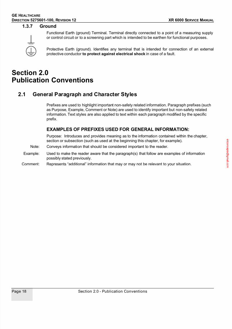
1.3.7 GroundFunctional Earth (ground) Terminal. Terminal directly connected to a point of a measuring supply
or control circuit or to a screening part which is intended to be earthen for functional purposes.
Protective Earth (ground). Identifies any terminal that is intended for connection of an external
protective conductor to protect against electrical shock in case of a fault.
Section 2.0 Publication Conventions
2.1 General Paragraph and Character Styles
Prefixes are used to highlight important non-safety related information. Paragraph prefixes (such
as Purpose, Example, Comment or Note) are used to identify important but non-safety related
information. Text styles are also applied to text within each paragraph modified by the specificprefix.
EXAMPLES OF PREFIXES USED FOR GENERAL INFORMATION:Purpose: Introduces and provides meaning as to the information contained within the chapter,
section or subsection (such as used at the beginning this chapter, for example).
Note: Conveys information that should be considered important to the reader.
Example: Used to make the reader aware that the paragraph(s) that follow are examples of information
possibly stated previously.
Comment: Represents “additional” information that may or may not be relevant to your situation.

7/24/2019 GE XR6000 X-Ray - Service Manual
http://slidepdf.com/reader/full/ge-xr6000-x-ray-service-manual 19/421
GE HEALTHCARE
DIRECTION 5275601-100, REVISION 12 XR 6000 SERVICE MANUAL
Preface - Publication Conventions Page 19
2.2 Page Layout
Headers and footers in this publication are designed to allow you to quickly identify your location.
The document part number and revision number appears in every header on every page. Odd
numbered page footers indicate the current chapter, its title and current page number. Even page
footers show the current section and its title, as well as the current page number.
2.3 Computer Screen Output/Input Text Character Styles
Within this publication, mono-spaced character styles (fonts) are used to indicate computer text
that’s either screen input and output. Mono-spaced fonts, such courier, are used to indicated text
direction. When you type at your keyboard, you are generating computer input. Occasionally you
will see the math operator “greater-than” and “less-than” symbols used to indicate the start and
finish of variable output. When reading text generated by the computer, you are reading it as
computer generated output. In addition to direction, characters are italicized (e.g. italics) to indicate
information specific to your system or site.
Example: FixedOutput
Thi s paragraph’ s f ont r epresent s comput er gener at ed scr een “f i xed” output .I t s out put i s f i xed f r omt he sense t hat i t does not var y f r omappl i cat i ont o appl i cat i on. I t ’ s t he most commonl y used styl e used to i ndi cat ef i l enames, pat hs and t ext t hat do not change f r om syst emt o syst em. Thechar act er st yl e used i s a f i xed wi dt h such as cour i er .
Example:
Variable Output
This paragraph’s font represents computer screen output that is
“variable”. It’s used to represent output that varies from application to
application or system to system. Variable output is sometimes found placed
between greater-than and less-than operators for clarification. For
example: <variable_ouput> or <3.45.120.3>. In both cases, the < and >
operators are not part of the actual input.
Publication Part Number & Revision Number Publication Title
An exclamation point in a triangle is usedto indicate important information to the user.
Paragraphs preceeded by Alphanumericcharacters (e.g. numbers) contain infor-mation that must be followed in a specific order.
Paragraphs preceeded by a symbol(e.g. bullets) contain information thathas no specific order.
The current chapter and its titleare always shown in the footer ofthe right (odd) page.
The current section and its titleare always shown in the footer ofthe left (even) page.

7/24/2019 GE XR6000 X-Ray - Service Manual
http://slidepdf.com/reader/full/ge-xr6000-x-ray-service-manual 20/421
GE HEALTHCARE DIRECTION 5275601-100, REVISION 12 XR 6000 SERVICE MANUAL
Page 20 Section 2.0 - Publication Conventions
Example: Fixed
Input
This paragraph’s font represents fixed input. It’s computer input that is
typed-in via the keyboard. Typed input that does not vary from application
to application or system to system. Fixed text the user is required to
supply as input. For example: cd /usr/3p
Example:
Variable Input
This paragraph’s font represents computer input that can vary from
application to application or system to system. With variable text, the
user is required to supply system dependent input or information. Variableinput sometimes is placed between greater-than and less-than operators.
For example: <variable_input>. In these cases, the (<>) operators would
be dropped prior to input. For example: ypcat hosts | grep <3.45.120.3>
would be typed into the computer as:
ypcat hosts | grep 3.45.120.3
without the greater-than and less-than operators.
2.4 Buttons, Switches and Keyboard Inputs (Hard & Soft Keys)
Different character styles are used to indicate actions requiring the reader to press either a hard or
soft button, switch or key. Physical hardware, such as buttons and switches, are called hard keys
because they are hard wired or mechanical in nature. A keyboard or on/off switch would be a hard
key. Software or computer generated buttons are called soft keys because they are software
generated. Software driven menu buttons are an example of such keys. Soft and hard keys are
represented differently in this publication.
Example: Hard
Keys
A power switch ON/OFF or a keyboard key like ENTER is indicated by applying a character style
that uses both over and under-lined bold text that is bold. This is a hard key.
Example: Soft
Keys
Whereas the computer MENU button that you would click with your mouse or touch with your hand
uses over and under-lined regular text. This is a soft key.

7/24/2019 GE XR6000 X-Ray - Service Manual
http://slidepdf.com/reader/full/ge-xr6000-x-ray-service-manual 21/421
GE HEALTHCARE
DIRECTION 5275601-100, REVISION 12 XR 6000 SERVICE MANUAL
Table of Contents Page 21
Table of Contents
3
5
Preface Publication Conventions ...................................................................................... 15
Section 1.0 Safety & Hazard Information ........................................................................... 151.1 Hazard Messages............................................................................................................ 15
1.2 Text Format of Signal Words........................................................................................... 15
1.3 Symbols and Pictorials Used........................................................................................... 16
1.3.1 SPECIAL NOTICES............................................................................................ 16
1.3.2 X-ray Tube .......................................................................................................... 171.3.3 Power ON and OFF............................................................................................ 17
1.3.4 Electrical Type .................................................................................................... 17
1.3.5 Electrical Current ................................................................................................ 17
1.3.6 Collimator............................................................................................................ 17
1.3.7 Ground................................................................................................................ 18
Section 2.0
Publication Conventions ................................................................................. 182.1 General Paragraph and Character Styles........................................................................ 18
2.2 Page Layout..................................................................................................................... 19
2.3 Computer Screen Output/Input Text Character Styles .................................................... 19
2.4 Buttons, Switches and Keyboard Inputs (Hard & Soft Keys)........................................... 20
Chapter 1 - Before You Begin............................................................................... 37
Section 1.0 Introduction ...................................................................................................... 37
Section 2.0
Objective and Scope of this Manual............................................................... 372.1 Pre-Installation Check...................................................................................................... 37
2.2 Installation Plan ............................................................................................................... 37
2.3 Interconnection ................................................................................................................ 37
2.4 Presentation..................................................................................................................... 38
Section 3.0 On-Site Requirements...................................................................................... 383.1 EMC Requirements ......................................................................................................... 38
3.2 Tools and Test Equipment............................................................................................... 38
3.3 Documentation................................................................................................................. 38
3.4 Audio and Visual.............................................................................................................. 39
Section 4.0 Description of System ..................................................................................... 39

7/24/2019 GE XR6000 X-Ray - Service Manual
http://slidepdf.com/reader/full/ge-xr6000-x-ray-service-manual 22/421
GE HEALTHCARE
DIRECTION 5275601-100, REVISION 12 XR 6000 SERVICE MANUAL
Page 22 Table of Contents
Chapter 2 - Physical Installation.......................................................................... 41
Section 1.0 System Installation Guide................................................................................ 41
Section 2.0 Installation Checklist........................................................................................ 44
Section 3.0 Before You Begin.............................................................................................. 48
Section 4.0 Integrated Table................................................................................................ 494.1 Radiography Table.......................................................................................................... 49
4.1.1 Unpacking and Positioning................................................................................. 49
4.1.2 Installation.......................................................................................................... 57
4.2 Tube Stand...................................................................................................................... 62
4.2.1 Unpacking .......................................................................................................... 62
4.2.2 Installation.......................................................................................................... 64
4.3 X-Ray Tube ..................................................................................................................... 694.4 Control Box and Collimator ............................................................................................. 72
4.5 Counterweight ................................................................................................................. 82
4.6 Cassette Tray.................................................................................................................. 83
4.7 Ion Chamber and Grid (Optional).................................................................................... 84
4.7.1 Install both Ion Chamber and Grid for system with standard Integrated table ... 85
4.7.2 Install the Grid Only for system with standard Integrated table.......................... 88
4.7.3 Install the Ion Chamber and Grid for system with advanced Integrated table.... 89
4.8 Electrical Connections..................................................................................................... 94
4.9 Install Cabinet Tray ......................................................................................................... 97
4.10 Table Top Installation and Leveling ................................................................................ 98
Section 5.0 System Console................................................................................................ 995.1 Without Console Stand ................................................................................................... 99
5.2 With Console Stand ........................................................................................................ 99
Section 6.0
Collimator Alignment ..................................................................................... 101
Section 7.0DAP Meter Installation................................................................. 102
Section 8.0 Standard Wall Stand....................................................................................... 105
8.1 Unpacking ..................................................................................................................... 1058.2 Installation..................................................................................................................... 108
8.3 Cassette Tray................................................................................................................ 111
8.4 Ion Chamber and Grid (Optional).................................................................................. 111
8.4.1 Install both Ion Chamber and Grid for standard wall stand.............................. 112
8.4.2 Install the Grid Only for standard wall stand .................................................... 115
8.4.3 Install both Ion chamber and grid..................................................................... 116
8.5 Counterweight ............................................................................................................... 120
Section 9.0
Final Cover Installation .................................................................................. 1219.1 Install Standard Tube Stand Covers ............................................................................. 121

7/24/2019 GE XR6000 X-Ray - Service Manual
http://slidepdf.com/reader/full/ge-xr6000-x-ray-service-manual 23/421
GE HEALTHCARE
DIRECTION 5275601-100, REVISION 12 XR 6000 SERVICE MANUAL
Table of Contents Page 23
9.2 Install Table Front Cover ............................................................................................... 124
9.3 Install Standard Wall Stand Covers............................................................................... 124
Section 10.0
Labels and Rating Plates............................................................................... 12510.1 System Console............................................................................................................. 125
10.2 Integrated Table............................................................................................................. 125
10.3 Cabinet .......................................................................................................................... 126
10.4 Wall Stand ..................................................................................................................... 126
Section 11.0
Installation Checklist ..................................................................................... 128
Section 12.0 Regulatory Tests and Final Steps................................................................. 13012.1 AEC Tests...................................................................................................................... 130
12.1.1 AEC Maximum MAS......................................................................................... 130
12.1.1.1 Overview ....................................................................................... 130
12.1.1.2 Procedure (50kV) .......................................................................... 130
12.1.2 AEC Minimum Exposure Time.......................................................................... 13012.1.2.1 Overview ....................................................................................... 130
12.1.2.2 Procedure...................................................................................... 130
12.1.3 Reproducibility Of Exposure ............................................................................. 131
12.1.3.1 Overview ....................................................................................... 131
12.1.3.2 Procedure...................................................................................... 131
> Calculation for Coefficient of Variation (C.V.):............................... 132
12.2 Final Installation and Admin Tasks................................................................................ 132
Chapter 3 - Configuraton & Calibration............................................................. 135
Section 1.0
Configuration & Calibration List ................................................................... 135
Section 2.0 Configuration & Calibration Contents.......................................................... 1352.1 System Configuration .................................................................................................... 135
2.2 X-Ray Tube Seasoning.................................................................................................. 136
2.2.1 Requirements ................................................................................................... 136
2.2.2 Procedure ......................................................................................................... 136
2.3 Service Software User Guide ........................................................................................ 139
2.3.1 Supplies ............................................................................................................ 139
2.3.2 Tools ................................................................................................................. 139
2.3.3 Safety Precautions............................................................................................ 1392.3.4 Prerequisites..................................................................................................... 139
2.3.5 Personnel.......................................................................................................... 139
2.3.6 Time.................................................................................................................. 139
2.3.7 Procedure ......................................................................................................... 139
2.3.7.1 Loading service software on service laptop .................................. 139
2.3.7.2 Using service software.................................................................. 139
2.3.7.3 Typical screen description............................................................. 141
2.4 Tube Configuration ........................................................................................................ 145
2.4.1 Supplies ............................................................................................................ 145
2.4.2 Tools ................................................................................................................. 146

7/24/2019 GE XR6000 X-Ray - Service Manual
http://slidepdf.com/reader/full/ge-xr6000-x-ray-service-manual 24/421
GE HEALTHCARE
DIRECTION 5275601-100, REVISION 12 XR 6000 SERVICE MANUAL
Page 24 Table of Contents
2.4.3 Safety Precautions........................................................................................... 146
2.4.4 Prerequisites .................................................................................................... 146
2.4.5 Personnel ......................................................................................................... 146
2.4.6 Time ................................................................................................................. 146
2.4.7 Procedure......................................................................................................... 146
2.4.7.1 Load software according to tube present in the installation.......... 146
2.4.7.2 Verify............................................................................................. 1462.5 Receptor Programming ................................................................................................. 146
2.5.1 Supplies ........................................................................................................... 146
2.5.2 Tools ................................................................................................................ 146
2.5.3 Safety Precautions........................................................................................... 146
2.5.4 Prerequisites .................................................................................................... 147
2.5.5 Personnel ......................................................................................................... 147
2.5.6 Time ................................................................................................................. 147
2.5.7 Procedure......................................................................................................... 147
2.5.7.1 Introduction................................................................................... 147
2.5.7.2 Calling the subroutine................................................................... 147
2.5.7.3 Parameter selection...................................................................... 147
2.5.7.4 Renard or normal scale for kv selection ....................................... 149
2.5.7.5 Date & Time.................................................................................. 149
2.6 Automatic AEC Calibration............................................................................................ 151
2.6.1 Supplies ........................................................................................................... 151
2.6.2 Tools ................................................................................................................ 151
2.6.3 Safety precautions ........................................................................................... 151
2.6.4 Personnel ......................................................................................................... 151
2.6.5 Time ................................................................................................................. 151
2.6.6 Prerequisites .................................................................................................... 151
2.6.7 PROCEDURE .................................................................................................. 151
2.6.7.1 Development equipment............................................................... 151
2.6.7.2 Preliminary Remarks .................................................................... 1522.6.7.3 Principle........................................................................................ 152
2.6.7.4 KVEF Adjustment ......................................................................... 153
2.7 CR AEC Calibration ...................................................................................................... 158
2.7.1 Systems with CR Filming Only......................................................................... 158
2.7.1.1 Program Generator with Default CR Parameters ......................... 158
2.7.1.2 CR Dose Adjustment .................................................................... 159
2.7.2 System with Film and CR Filming Combined................................................... 159
2.7.3 Final Adjustment .............................................................................................. 160
2.7.3.1 Disable Unused Film-Screen........................................................ 160
2.7.3.2 Perform Checksum....................................................................... 160
2.7.3.3 Save Memory................................................................................ 160
2.8 Checksum Validation .................................................................................................... 160
2.8.1 Supplies ........................................................................................................... 160
2.8.2 Tools ................................................................................................................ 160
2.8.3 Safety Precautions........................................................................................... 160
2.8.4 Prerequisites .................................................................................................... 160
2.8.5 Personnel ......................................................................................................... 160
2.8.6 Time ................................................................................................................. 160
2.8.7 PROCEDURE .................................................................................................. 161
2.8.7.1 Preliminary Remarks .................................................................... 161
2.8.7.2 Checksum Validation.................................................................... 161
2.9 Backup and Restore Database Parameters.................................................................. 162
7/24/2019 GE XR6000 X-Ray - Service Manual
http://slidepdf.com/reader/full/ge-xr6000-x-ray-service-manual 25/421
GE HEALTHCARE
DIRECTION 5275601-100, REVISION 12 XR 6000 SERVICE MANUAL
Table of Contents Page 25
2.9.1 Supplies ............................................................................................................ 162
2.9.2 Tools ................................................................................................................. 162
2.9.3 Safety Precautions............................................................................................ 162
2.9.4 Prerequisites..................................................................................................... 162
2.9.5 Personnel.......................................................................................................... 162
2.9.6 Time.................................................................................................................. 162
2.9.7 Applicability....................................................................................................... 1622.9.8 Procedure ......................................................................................................... 162
2.9.8.1 CPU memory backup .................................................................... 162
2.9.8.2 CPU memory restore..................................................................... 163
2.9.8.3 Error messages............................................................................. 163
2.10 Dosimetric Calibration.................................................................................................... 163
2.10.1 Dose/DAP accuracy check procedure .............................................................. 163
2.10.2 Dose/DAP accuracy maintenance.................................................................... 164
Chapter 4 - Functional Checks ........................................................................... 165
Section 1.0 Introduction .................................................................................................... 165
Section 2.0 Tools and Test Equipment ............................................................................ 166
Section 3.0
Operational Checks........................................................................................ 1673.1 System Power Up.......................................................................................................... 167
3.2 Tube Assembly Operation ............................................................................................. 167
3.2.1 Tube Stand Longitudinal Movement ................................................................. 168
3.2.2 Tube Stand Rotation......................................................................................... 168
3.2.3 Tube Arm Vertical Movement ........................................................................... 168
3.2.4 X-Ray Tube Angulation..................................................................................... 168
3.2.5 X-Ray Tube Tilting............................................................................................ 169
3.2.6 Table Top Movement Checks........................................................................... 169
3.2.7 Cassette Tray Movement.................................................................................. 169
3.2.8 Collimator Rotation ........................................................................................... 169
3.2.9 Collimator Light Timer....................................................................................... 169
3.2.10 Wall Stand Carriage Vertical Movement........................................................... 169
Section 4.0 Performance Checks...................................................................................... 1694.1 Console.......................................................................................................................... 169
4.2 Accuracy of X-Ray Field and Light Field Alignment....................................................... 170
4.2.1 Requirements ................................................................................................... 170
4.2.2 Test Method...................................................................................................... 170
4.3 Alignment of Centers of X-Ray Field and Image Receptor............................................ 173
4.3.1 Requirements ................................................................................................... 173
4.3.2 Test Method...................................................................................................... 173
4.4 Image Quality................................................................................................................. 174
4.4.1 Test Method...................................................................................................... 174
4.5 Tube Voltage Accuracy.................................................................................................. 175
4.5.1 Tools ................................................................................................................. 175
4.5.2 Requirements ................................................................................................... 175
4.5.3 Procedure ......................................................................................................... 175

7/24/2019 GE XR6000 X-Ray - Service Manual
http://slidepdf.com/reader/full/ge-xr6000-x-ray-service-manual 26/421
GE HEALTHCARE
DIRECTION 5275601-100, REVISION 12 XR 6000 SERVICE MANUAL
Page 26 Table of Contents
4.6 Tube Current ................................................................................................................. 175
4.6.1 Requirements................................................................................................... 175
4.6.2 Procedure......................................................................................................... 175
4.7 Exposure Time .............................................................................................................. 176
4.7.1 Requirements................................................................................................... 176
4.7.2 Procedure......................................................................................................... 176
4.8 Exposure mAs............................................................................................................... 1764.8.1 Requirements................................................................................................... 176
4.8.2 Procedure......................................................................................................... 176
4.9 Automatic Exposure Control (AEC) - Optional .............................................................. 177
4.9.1 Table AEC........................................................................................................ 177
4.9.2 Wall Stand AEC ............................................................................................... 177
4.10 Collimator Light Timer ................................................................................................... 177
Section 5.0 HHS Test.......................................................................................................... 178
Chapter 5 - JEDI GENERATOR THEORY AND FUNCTIONAL DESCRIPTION 179
Section 1.0
Theory.............................................................................................................. 1791.1 Glossary........................................................................................................................ 179
1.2 JEDI HIGH LEVEL BLOCK DIAGRAM......................................................................... 180
Section 2.0 Theory Presentation....................................................................................... 1812.1 Introduction ................................................................................................................... 181
2.2 Standard Features ........................................................................................................ 181
2.3 Applications................................................................................................................... 181
2.4 Architecture ................................................................................................................... 182
2.4.1 A Kernel ........................................................................................................... 182
2.4.2 Options Depending on the Application............................................................. 182
2.5 A Packaging Architecture.............................................................................................. 184
2.5.1 Auxiliaries Box.................................................................................................. 184
2.5.2 Power Box........................................................................................................ 184
2.5.3 AC/DC Box....................................................................................................... 184
2.5.4 System Interface Box....................................................................................... 184
2.5.5 Optional Boxes................................................................................................. 184
Section 3.0 Technique Factors Measurement Criteria.................................................... 1863.1 kV Accuracies ............................................................................................................... 186
3.2 mA Accuracies .............................................................................................................. 186
3.3 mAs Accuracies ............................................................................................................ 186
3.4 Exposure Time Accuracies ........................................................................................... 186
Chapter 6 - Exception Handling And Error Codes ........................................... 187
Section 1.0 Exception Handling ........................................................................................ 1871.1 Diagnostics.................................................................................................................... 187
1.2 Power-On Diagnostic .................................................................................................... 187
7/24/2019 GE XR6000 X-Ray - Service Manual
http://slidepdf.com/reader/full/ge-xr6000-x-ray-service-manual 27/421
GE HEALTHCARE
DIRECTION 5275601-100, REVISION 12 XR 6000 SERVICE MANUAL
Table of Contents Page 27
1.3 Live Diagnostics............................................................................................................. 187
1.4 Error Code Structure...................................................................................................... 187
1.5 Simplified Error Code Definition..................................................................................... 188
1.6 Generator Phase Definition ........................................................................................... 188
1.7 Error Class Definition..................................................................................................... 188
1.8 Error Code Definition ..................................................................................................... 189
1.9 Data Associated With The Error Code........................................................................... 1901.10 Number Of Occurrences................................................................................................ 190
1.11 Date & Time................................................................................................................... 190
Section 2.0 Error Codes, Diagnostics & Troubleshooting ............................................. 1902.1 Introduction.................................................................................................................... 190
2.2 Power On Diagnostics ................................................................................................... 190
2.3 Error Code List............................................................................................................... 191
2.4 Error Reporting .............................................................................................................. 195
2.5 Diagnostics .................................................................................................................... 195
2.6 Detailed Error Description & Troubleshooting Guide..................................................... 195
2.6.1 Errors ................................................................................................................ 1972.6.1.1 Tube spits detection Errors (Code 30) .......................................... 197
2.6.1.2 Anode Rotation errors (Code 40) .................................................. 197
2.6.1.3 Filament Heater errors (Code 50) ................................................. 199
2.6.1.4 Exposure errors (Code 60)................................. 201
2.6.1.5 Power supply (Code 70) ................................... 203
2.6.1.6 Hardware errors (Code 80)................................. 203
2.6.1.7 Application errors (Code 90) ......................................................... 205
2.6.1.8 Communication errors (code 100)................................................. 205
2.6.1.9 Thermal errors (code 110) ................................. 205
2.6.1.10 Manipulation errors (code 120) ............................. 206
2.7 Warning Errors............................................................................................................... 206
2.8 Other Failures................................................................................................................ 207
2.9 Heating Function diagnostics......................................................................................... 209
2.10 Rotation Function diagnostics........................................................................................ 210
2.11 Inverter in Short Circuit Function diagnostics ................................................................ 210
2.12 AEC diagnostics ............................................................................................................ 213
2.13 No Load HV diagnostics ................................................................................................ 213
2.14 Inverter Gate Command diagnostics ............................................................................. 214
Section 3.0
Console Troubleshooting & Error Codes .................................................... 2163.1 Error Codes................................................................ 216
3.2 Console Troubleshooting............................................................................................... 2163.2.1 System Error (C01-0001).................................................................................. 216
3.2.2 Memory Error on Console Control Board (C02-0001) ...................................... 217
3.2.3 Membrane Button Error (C02-1000) ................................................................. 218
3.2.4 JEDI Communication Error (C03-0001)............................................................ 219
3.2.5 APR Random or All (C04-0001) ....................................................................... 219
3.2.6 No AEC Config (C04-0002) .............................................................................. 219
3.2.7 Overlimit (C04-0003) ........................................................................................ 219
3.2.8 Phase Missing (C04-0004) ............................................................................... 220
3.2.9 Generator Error (C05-0001) ............................................................................. 220
3.2.10 Other Troubleshooting...................................................................................... 220

7/24/2019 GE XR6000 X-Ray - Service Manual
http://slidepdf.com/reader/full/ge-xr6000-x-ray-service-manual 28/421
GE HEALTHCARE
DIRECTION 5275601-100, REVISION 12 XR 6000 SERVICE MANUAL
Page 28 Table of Contents
3.2.10.1 LED Unlit Failure........................................................................... 220
3.2.10.2 Buzzer Failure............................................................................... 220
3.2.10.3 LCD Display Failure...................................................................... 220
3.2.10.4 LCD Display Faintness ................................................................. 220
3.2.10.5 Power Un failure ........................................................................... 221
Section 4.0 PDU
Troubleshooting ............................................................................................. 2214.1 PDU Troubleshooting.................................................................................................... 221
4.1.1 No Console Power ........................................................................................... 221
4.1.2 No EM Lock Power or No Collimator Power .................................................... 222
4.1.3 No Generator Power ........................................................................................ 223
Chapter 7 - Planned Maintenance...................................................................... 225
Section 1.0 Preventive Maintenance Action List ............................................................. 225
Section 2.0
Preventive Maintenance................................................................................. 2272.1 General Cleaning and Painting ..................................................................................... 227
2.1.1 Supplies ........................................................................................................... 227
2.1.2 Tools ................................................................................................................ 227
2.1.3 Safety Precautions........................................................................................... 227
2.1.4 prerequisites..................................................................................................... 227
2.1.5 Personnel ......................................................................................................... 227
2.1.6 Time ................................................................................................................. 227
2.1.7 Procedure......................................................................................................... 227
2.2 Visual Inspection ........................................................................................................... 227
2.2.1 Supplies ........................................................................................................... 227
2.2.2 Tools ................................................................................................................ 228
2.2.3 Safety Precautions........................................................................................... 228
2.2.4 Prerequisites .................................................................................................... 228
2.2.5 Personnel ......................................................................................................... 228
2.2.6 Time ................................................................................................................. 228
2.2.7 Procedure......................................................................................................... 228
2.3 Functional Checks......................................................................................................... 228
2.3.1 Supplies ........................................................................................................... 228
2.3.2 Tools ................................................................................................................ 228
2.3.3 Safety Precautions........................................................................................... 228
2.3.4 Prerequisites .................................................................................................... 228
2.3.5 Personnel ......................................................................................................... 2282.3.6 Time ................................................................................................................. 228
2.3.7 Procedure......................................................................................................... 229
2.4 Table Base Maintenance .............................................................................................. 229
2.4.1 Supplies ........................................................................................................... 229
2.4.2 Tools ................................................................................................................ 229
2.4.3 Safety Precautions........................................................................................... 229
2.4.4 Prerequisites .................................................................................................... 229
2.4.5 Personnel ......................................................................................................... 229
2.4.6 Time ................................................................................................................. 229
2.4.7 Procedure......................................................................................................... 229

7/24/2019 GE XR6000 X-Ray - Service Manual
http://slidepdf.com/reader/full/ge-xr6000-x-ray-service-manual 29/421
GE HEALTHCARE
DIRECTION 5275601-100, REVISION 12 XR 6000 SERVICE MANUAL
Table of Contents Page 29
2.5 Patient Support Maintenance ........................................................................................ 230
2.5.1 Supplies ............................................................................................................ 230
2.5.2 Tools ................................................................................................................. 230
2.5.3 Safety Precautions............................................................................................ 230
2.5.4 Prerequisites..................................................................................................... 230
2.5.5 Personnel.......................................................................................................... 230
2.5.6 Time.................................................................................................................. 2302.5.7 Procedure ......................................................................................................... 230
2.6 Cassette Tray Carriage Maintenance............................................................................ 230
2.6.1 Supplies ............................................................................................................ 230
2.6.2 Tools ................................................................................................................. 230
2.6.3 Safety Precautions............................................................................................ 230
2.6.4 Prerequisites..................................................................................................... 231
2.6.5 Personnel.......................................................................................................... 231
2.6.6 Time.................................................................................................................. 231
2.6.7 Procedure ......................................................................................................... 231
2.7 Tube Stand and Wall Stand Maintenance ..................................................................... 231
2.7.1 Supplies ............................................................................................................ 231
2.7.2 Tools ................................................................................................................. 231
2.7.3 Safety Precautions............................................................................................ 231
2.7.4 Prerequisites..................................................................................................... 231
2.7.5 Personnel.......................................................................................................... 231
2.7.6 Time.................................................................................................................. 231
2.7.7 Procedure ......................................................................................................... 232
2.8 Generator Functional Checks........................................................................................ 232
2.8.1 Supplies ............................................................................................................ 232
2.8.2 Tools ................................................................................................................. 232
2.8.3 Safety Precautions............................................................................................ 232
2.8.4 Prerequisites..................................................................................................... 232
2.8.5 Personnel.......................................................................................................... 2322.8.6 Time.................................................................................................................. 232
2.8.7 Procedure ......................................................................................................... 232
2.8.7.1 Test exposure................................................................................ 232
> Post display initialization: .............................................................. 232
> mA accuracy.................................................................................. 233
> AEC functionality check (if existing) .............................................. 233
2.8.7.2 Record last error codes................................................................. 233
2.8.7.3 Record results on counters ........................................................... 234
2.8.7.4 Check technique factors................................................................ 235
2.8.7.5 Tighten terminals and remove dust............................................... 235
2.9 HV Cable and Sockets Regreasing ............................................................................... 235
2.9.1 Supplies ............................................................................................................ 2352.9.2 Tools ................................................................................................................. 235
2.9.3 Safety Precautions............................................................................................ 235
2.9.4 Prerequisites..................................................................................................... 235
2.9.5 Personnel.......................................................................................................... 235
2.9.6 Time.................................................................................................................. 235
2.9.7 Procedure ......................................................................................................... 235
2.10 Replace Generator NonVolatile Parameters RAM ........................................................ 235
2.10.1 Supplies ............................................................................................................ 235
2.10.2 Tools................................................................................................................. 236
2.10.3 Safety Precautions............................................................................................ 236

7/24/2019 GE XR6000 X-Ray - Service Manual
http://slidepdf.com/reader/full/ge-xr6000-x-ray-service-manual 30/421
GE HEALTHCARE
DIRECTION 5275601-100, REVISION 12 XR 6000 SERVICE MANUAL
Page 30 Table of Contents
2.10.4 Prerequisites .................................................................................................... 236
2.10.5 Personnel ......................................................................................................... 236
2.10.6 Time ................................................................................................................. 236
2.10.7 Procedure......................................................................................................... 236
2.10.7.1 Remove and Replace the RAM .................................................... 236
2.10.7.2 Download Database ..................................................................... 236
Chapter 8 - Renewal Parts.................................................................................. 237
Section 1.0
Renewal Parts List.......................................................................................... 2371.1 Bearing kit 5196543, 5196544 ...................................................................................... 247
1.2 X-Ray Tube (5192454) / Collimator (5189248) Replacement....................................... 248
1.3 Collimator Lamp (5136302) Replacement .................................................................... 248
1.4 Rotundity Electricity Brake Assembly (5184986) Replacement .................................... 250
1.5 Wall Stand Cassette Tray Spring Kit (5196542) Replacement ..................................... 252
1.6 Console Replacement................................................................................................... 253
1.7 Console Main Board Replacement ............................................................................... 254
1.8 Hand Switch Replacement............................................................................................ 255
1.9 TAV Board Replacement .............................................................................................. 255
1.10 Table Top IF Board (5335073) Replacement................................................................ 257
Section 2.0 JEDI Generator Renewal Parts...................................................................... 2572.1 Introduction ................................................................................................................... 257
2.2 JEDI Generator Renewal Parts List .............................................................................. 257
2.3 FRU Information............................................................................................................ 258
2.4 Jedi 50 R 1T Structure .................................................................................................. 259
2.5 Renewal Parts............................................................................................................... 260
2.6 Cables........................................................................................................................... 263Section 3.0
JEDI Generator Disassembly/Reassembly................................................... 2643.1 Introduction ................................................................................................................... 264
3.2 Tools ............................................................................................................................. 264
3.3 HV Tank, 1 Tube, 1-3 Phase......................................................................................... 265
3.3.1 Supplies ........................................................................................................... 265
3.3.2 Tools ................................................................................................................ 265
3.3.3 Safety Precautions........................................................................................... 265
3.3.4 Prerequisites .................................................................................................... 265
3.3.5 Personnel ......................................................................................................... 266
3.3.6 Time ................................................................................................................. 2663.3.7 Disassembly..................................................................................................... 266
3.3.8 Reassembly ..................................................................................................... 268
3.3.9 Verify ................................................................................................................ 269
3.4 Inverter Mid-Power Assembly ....................................................................................... 269
3.4.1 Supplies ........................................................................................................... 269
3.4.2 Tools ................................................................................................................ 270
3.4.3 Safety Precautions........................................................................................... 270
3.4.4 Prerequisites .................................................................................................... 270
3.4.5 Personnel ......................................................................................................... 270
3.4.6 Time ................................................................................................................. 270

7/24/2019 GE XR6000 X-Ray - Service Manual
http://slidepdf.com/reader/full/ge-xr6000-x-ray-service-manual 31/421
GE HEALTHCARE
DIRECTION 5275601-100, REVISION 12 XR 6000 SERVICE MANUAL
Table of Contents Page 31
3.4.7 Disassembly ..................................................................................................... 271
3.4.7.1 Remove the Auxiliary Unit............................................................. 272
3.4.7.2 Remove the Interface Unit............................................................. 272
3.4.7.3 Remove the AC/DC Unit and the support plate............................. 273
3.4.7.4 Remove the Inverter Mid Power Assembly ................................... 274
3.4.8 Reassembly...................................................................................................... 276
3.4.9 Verify................................................................................................................. 2783.5 I/F Board RAD ............................................................................................................... 278
3.5.1 Supplies ............................................................................................................ 278
3.5.2 Tools ................................................................................................................. 279
3.5.3 Safety Precautions............................................................................................ 279
3.5.4 Prerequisites..................................................................................................... 279
3.5.5 Personnel.......................................................................................................... 279
3.5.6 Time.................................................................................................................. 279
3.5.7 Disassembly ..................................................................................................... 279
3.5.7.1 Remove the I/F Board Rad............................................................ 279
3.5.8 Reassembly...................................................................................................... 280
3.6 KV Board RAD............................................................................................................... 280
3.6.1 Supplies ............................................................................................................ 280
3.6.2 Tools ................................................................................................................. 280
3.6.3 Safety Precautions............................................................................................ 280
3.6.4 Prerequisites..................................................................................................... 280
3.6.5 Personnel.......................................................................................................... 281
3.6.6 Time.................................................................................................................. 282
3.6.7 Disassembly ..................................................................................................... 282
3.6.7.1 Remove the Auxiliary Unit............................................................. 282
3.6.7.2 Remove the Interface Unit............................................................. 282
3.6.7.3 Remove the kV Control Board....................................................... 282
3.6.8 Reassembly...................................................................................................... 282
3.6.9 Verify................................................................................................................. 2823.7 EMC Board 3 Phases.................................................................................................... 283
3.7.1 Supplies ............................................................................................................ 283
3.7.2 Tools ................................................................................................................. 283
3.7.3 Safety Precautions............................................................................................ 283
3.7.4 Prerequisites..................................................................................................... 283
3.7.5 Personnel.......................................................................................................... 283
3.7.6 Time.................................................................................................................. 283
3.7.7 Disassembly ..................................................................................................... 284
3.7.7.1 Remove the AC/DC Unit ............................................................... 284
3.7.7.2 Remove the EMC Board ............................................................... 285
3.7.8 Reassembly...................................................................................................... 285
3.7.9 Verify................................................................................................................. 285
3.8 AC/DC 3 PH Mid Power Assembly................................................................................ 285
3.8.1 Supplies ............................................................................................................ 285
3.8.2 Tools ................................................................................................................. 285
3.8.3 Safety Precautions............................................................................................ 286
3.8.4 Prerequisites..................................................................................................... 286
3.8.5 Disassembly ..................................................................................................... 286
3.8.5.1 Remove the AC/DC Unit ............................................................... 286
3.8.5.2 Remove the AC/DC Board ............................................................ 287
3.8.5.3 Remove the Rectifier Block........................................................... 287
3.8.6 Reassembly...................................................................................................... 287

7/24/2019 GE XR6000 X-Ray - Service Manual
http://slidepdf.com/reader/full/ge-xr6000-x-ray-service-manual 32/421
GE HEALTHCARE
DIRECTION 5275601-100, REVISION 12 XR 6000 SERVICE MANUAL
Page 32 Table of Contents
3.8.7 Verify ................................................................................................................ 288
3.9 Inverter Coil Mid Power Assembly ................................................................................ 288
3.9.1 Supplies ........................................................................................................... 288
3.9.2 Tools ................................................................................................................ 288
3.9.3 Safety Precautions........................................................................................... 288
3.9.4 Prerequisites .................................................................................................... 288
3.9.5 Personnel ......................................................................................................... 2883.9.6 Time ................................................................................................................. 289
3.9.7 Disassembly..................................................................................................... 289
3.9.7.1 Remove the Auxiliary Unit and the Interface Unit ......................... 289
3.9.7.2 Remove the AC/DC Unit and the support plate............................ 289
3.9.7.3 Remove the Inverter Coil Mid Power Assembly ........................... 289
3.9.8 Reassembly ..................................................................................................... 290
3.9.9 Verify ................................................................................................................ 292
3.10 Capacitor Inverter Assembly......................................................................................... 292
3.10.1 Supplies ........................................................................................................... 292
3.10.2 Tools ................................................................................................................ 292
3.10.3 Safety Precautions........................................................................................... 292
3.10.4 Prerequisites .................................................................................................... 292
3.10.5 Personnel ......................................................................................................... 292
3.10.6 Time ................................................................................................................. 292
3.10.7 Disassembly..................................................................................................... 292
3.10.7.1 Remove the Auxiliary Unit and the Interface Unit ......................... 292
3.10.7.2 Remove the AC/DC Unit and the Support Plate........................... 292
3.10.7.3 Remove the Capacitor Inverter Assembly .................................... 293
3.10.8 Reassembly ..................................................................................................... 294
3.10.9 Verify ................................................................................................................ 297
3.11 LV Power Supply 3 Phase Board.................................................................................. 297
3.11.1 Supplies ........................................................................................................... 297
3.11.2 Tools ................................................................................................................ 2973.11.3 Safety Precautions........................................................................................... 297
3.11.4 Prerequisites .................................................................................................... 297
3.11.5 Personnel ......................................................................................................... 297
3.11.6 Time ................................................................................................................. 297
3.11.7 Disassembly..................................................................................................... 298
3.11.7.1 Remove the Auxiliary Unit ............................................................ 298
3.11.7.2 Remove the LV Power Supply Board ........................................... 299
3.11.8 Reassembly ..................................................................................................... 299
3.11.9 Verify ................................................................................................................ 299
3.12 Filament Board 1 INV.................................................................................................... 300
3.12.1 Supplies ........................................................................................................... 300
3.12.2 Tools ................................................................................................................ 300
3.12.3 Safety Precautions........................................................................................... 300
3.12.4 Prerequisites .................................................................................................... 300
3.12.5 Personnel ......................................................................................................... 300
3.12.6 Time ................................................................................................................. 300
3.12.7 Disassembly..................................................................................................... 301
3.12.7.1 Remove the Auxiliary Unit ............................................................ 301
3.12.7.2 Remove the Filament Board......................................................... 302
3.12.8 Reassembly ..................................................................................................... 302
3.12.9 Verify ................................................................................................................ 302
3.13 Rotor Board High Speed............................................................................................... 302
7/24/2019 GE XR6000 X-Ray - Service Manual
http://slidepdf.com/reader/full/ge-xr6000-x-ray-service-manual 33/421
GE HEALTHCARE
DIRECTION 5275601-100, REVISION 12 XR 6000 SERVICE MANUAL
Table of Contents Page 33
3.13.1 Supplies ............................................................................................................ 302
3.13.1.1 Tools.............................................................................................. 303
3.13.2 Safety Precautions............................................................................................ 303
3.13.3 Prerequisites..................................................................................................... 303
3.13.4 Personnel.......................................................................................................... 303
3.13.5 Time.................................................................................................................. 303
3.13.6 Disassembly ..................................................................................................... 3033.13.6.1 Remove the Auxiliary Unit ............................................................. 303
3.13.6.2 Remove the Rotor Board............................................................... 304
3.13.7 Reassembly...................................................................................................... 304
3.13.8 Verify................................................................................................................. 305
3.14 AEC Board..................................................................................................................... 305
3.14.1 Supplies ............................................................................................................ 305
3.14.2 Tools................................................................................................................. 305
3.14.3 Safety Precautions............................................................................................ 305
3.14.4 Prerequisites..................................................................................................... 305
3.14.5 Personnel.......................................................................................................... 305
3.14.6 Time.................................................................................................................. 305
3.14.7 Disassembly ..................................................................................................... 306
3.14.7.1 Remove the Auxiliary Unit ............................................................. 306
3.14.7.2 Remove the AEC Board................................................................ 306
3.14.8 Reassembly...................................................................................................... 307
3.14.9 Verify................................................................................................................. 307
Chapter 9 - Service Tool Job Cards................................................................... 309
Section 1.0 Software Download / Upgrade ...................................................................... 3091.1 Supplies......................................................................................................................... 309
1.2 Tools.............................................................................................................................. 3091.3 Safety Precautions......................................................................................................... 309
1.4 Prerequisites.................................................................................................................. 309
1.5 Personnel....................................................................................................................... 309
1.6 Time............................................................................................................................... 309
1.7 Procedure ...................................................................................................................... 309
1.7.1 Load Software File on Service Laptop.............................................................. 309
1.7.2 Unzip software file ............................................................................................ 309
1.7.3 Software download ........................................................................................... 310
Section 2.0 Tube Replacement Software Procedure ...................................................... 3112.1 Supplies......................................................................................................................... 311
2.2 Tools.............................................................................................................................. 311
2.3 Safety Precautions......................................................................................................... 311
2.4 Prerequisites.................................................................................................................. 311
2.5 Personnel....................................................................................................................... 311
2.6 Time............................................................................................................................... 312
2.7 Procedure ...................................................................................................................... 312
2.7.1 Perform a Database backup............................................................................. 312
2.7.2 Reset Tube Data tracking counter and error log............................................... 312
2.7.3 Verify new tube operation, clear error log......................................................... 314
2.7.4 Generator Counter Reading Record................................................................. 314

7/24/2019 GE XR6000 X-Ray - Service Manual
http://slidepdf.com/reader/full/ge-xr6000-x-ray-service-manual 34/421
GE HEALTHCARE
DIRECTION 5275601-100, REVISION 12 XR 6000 SERVICE MANUAL
Page 34 Table of Contents
2.7.5 Tube Database Download................................................................................ 315
Chapter 10 - Schematics .................................................................................... 317
Section 1.0
MIS Map ........................................................................................................... 317
1.1 Jedi 50 R 1T Cabling..................................................................................................... 321
Section 2.0 Central Listings............................................................................................... 3232.1 kV Measure Board ........................................................................................................ 323
2.2 Filament Board 1 Inv. .................................................................................................... 324
2.3 Rotation Board High Speed .......................................................................................... 325
2.3.1 Indicators.......................................................................................................... 326
2.3.2 J2 Wiring .......................................................................................................... 326
2.4 LV Power Supply 3 PH Board ....................................................................................... 327
2.5 Gate Command Board .................................................................................................. 328
2.6 Dual Snub Board........................................................................................................... 329
2.7 kV Control Board........................................................................................................... 3302.7.1 Switches and Jumpers ..................................................................................... 331
2.7.2 Indicators.......................................................................................................... 331
2.7.3 Non Volatile RAM............................................................................................. 331
2.8 AC/DC 3 Phase board................................................................................................... 332
2.9 I/F Board RAD V1 ......................................................................................................... 333
2.10 I/F Board RAD V2 ......................................................................................................... 334
2.11 AEC Board .................................................................................................................... 335
2.11.1 Test Points ....................................................................................................... 335
2.12 AEC Board V2............................................................................................................... 336
2.13 Test Points .................................................................................................................... 336
Section 3.0 Schematics...................................................................................................... 3373.1 PDU Connection Diagram............................................................................................. 337
3.2 Table Electrical Schematics .......................................................................................... 338
3.3 A61001C Console Control Board Circuit Diagram........................................................ 341
3.4 Jedi Generator TAV Interface Board............................................................................. 355
3.5 I/F Board RAD Electrical ............................................................................................... 359
3.6 I/F Board RAD V2 Electrical.......................................................................................... 363
3.7 Rotor board ................................................................................................................... 367
3.8 Heater board ................................................................................................................. 378
3.9 LVPS board................................................................................................................... 385
3.10 Inverter.......................................................................................................................... 3873.11 Gate cmd....................................................................................................................... 388
3.12 Dual snub...................................................................................................................... 391
3.13 AC/DC board................................................................................................................. 392
3.14 AEC board..................................................................................................................... 393
3.15 Rad IF ........................................................................................................................... 397
Chapter 11 - MIS Chart........................................................................................ 401
Section 1.0 Scope............................................................................................................... 401

7/24/2019 GE XR6000 X-Ray - Service Manual
http://slidepdf.com/reader/full/ge-xr6000-x-ray-service-manual 35/421
GE HEALTHCARE
DIRECTION 5275601-100, REVISION 12 XR 6000 SERVICE MANUAL
Table of Contents Page 35
Section 2.0 How to Use...................................................................................................... 401
Section 3.0 MIS Charts....................................................................................................... 4023.1 System Console............................................................................................................. 402
3.1.1 J1 Handswitch Interface, 5184620 ................................................................... 402
3.1.2 J2 FW Download Serial Port, 5194292............................................................. 402
3.1.3 J3 Power and RTL Interface, 5183903............................................................. 403
3.1.4 J4 Generator Interface, 5182354...................................................................... 404
3.2 Generator....................................................................................................................... 406
3.2.1 Generator Power Cable, 5196454.................................................................... 406
3.2.2 Generator Grounding Cable, 5196643 ............................................................. 406
3.3 Table.............................................................................................................................. 406
3.3.1 TM1-XS105 Cable, 5193103 ............................................................................ 406
3.3.2 Table Grounding Cable 1, 5193105.................................................................. 407
3.3.3 Table Grounding Cable 2, 5193106.................................................................. 407
3.3.4 Table Grounding Cable 3, 5193107.................................................................. 407
3.3.5 Table Grounding Cable 5, 5193109.................................................................. 4073.3.6 Table Power Cable, 5193607 ........................................................................... 408
3.3.6.1 Table MC7 Cable, 5197242 .......................................................... 408
3.3.7 Table Cable No1, 5197244............................................................................... 409
Chapter A - Electromagnetic Compatibility (EMC) ........................................... 411
Section 1.0 Compliance Statement................................................................................... 411
Section 2.0 Compatibility Tables ...................................................................................... 4122.1 Electromagnetic Emission ............................................................................................. 412
2.2 Electromagnetic Immunity ............................................................................................. 413
Section 3.0
Use Recommendations.................................................................................. 416
Section 4.0 Installation Recommendations..................................................................... 4164.1 Cable Shielding & Grounding ........................................................................................ 416
4.2 Subsystem & Accessories Power Supply Distribution .................................................. 416
4.3 Stacked Components & Equipment............................................................................... 416
4.4 Low Frequency Magnetic Field...................................................................................... 417
4.5 Electrostatic Discharge Environment & Recommendations .......................................... 417
Chapter B - Revision History.............................................................................. 419

7/24/2019 GE XR6000 X-Ray - Service Manual
http://slidepdf.com/reader/full/ge-xr6000-x-ray-service-manual 36/421
GE HEALTHCARE
DIRECTION 5275601-100, REVISION 12 XR 6000 SERVICE MANUAL
Page 36 Table of Contents
7/24/2019 GE XR6000 X-Ray - Service Manual
http://slidepdf.com/reader/full/ge-xr6000-x-ray-service-manual 37/421
GE HEALTHCARE
DIRECTION 5275601-100, REVISION 12 XR 6000 SERVICE MANUAL
Chapter 1 - Before You Begin Page 37
Chapter 1 - Before You Begin
Section 1.0
IntroductionThe goal of this document is to guide the service representative through an entire X-ray room
installation and to provide Diagnostic and Calibration information for troubleshooting and repair.
The following On-site Requirements must be accounted for prior to beginning installation of the
system.
Section 2.0
Objective and Scope of this ManualThis direction will lead you in a correct sequence through the manuals needed to install the
equipment. Following the suggested sequence will result in an orderly installation. However,extenuating circumstances may dictate a deviation from the recommended sequence. Feel free to
deviate, but keep track of your progress by checking off the tasks in the flowchart as you complete
them.
Check equipment according to the packing list for your system against the main catalog numbers
in the FDO (Field Delivery Order). Also, verify that all the manuals are present in the binders
according to the Table of Contents.
2.1 Pre-Installation Check
Pre-installation planning should be complete. Inspect the pre-installation “checklist”, found in GEHC
document 5275600-100 (XR 6000 System Pre-Installation Manual), and verify that the tasks
specified have been completed. Immediately arrange for completion of any tasks still notcompleted.
2.2 Installation Plan
The main steps in the installation plan are easily seen by referring to the Table of Contents of this
document. The plan objectives are to:
Give a logical installation order which recognizes mechanical and electrical interface areas.
Test and adjust each subsystem independently.
To obtain a good overall view of how these objectives are to be achieved review the Table of
Contents for this document before beginning the installation work. Then, if it is necessary to deviate
from the stated plan, you will be aware of the essential interface area. This document will give youthe information required to make another effective plan that applies to particular situations.
2.3 Interconnection
Interconnection of products by furnished cables or contractor supplied wiring is indicated by
numbered MIS runs in the installation sections. Run interconnect charts are available, which
describe the connection and function of each wire. For XR 6000 System, refer to the following:
• XR 6000 System Schematics (Chapter 10)
• XR 6000 System MIS Chart (Chapter 11)

7/24/2019 GE XR6000 X-Ray - Service Manual
http://slidepdf.com/reader/full/ge-xr6000-x-ray-service-manual 38/421
GE HEALTHCARE
DIRECTION 5275601-100, REVISION 12 XR 6000 SERVICE MANUAL
Page 38 Section 3.0 - On-Site Requirements
2.4 Presentation
The procedures in this steering manual are presented in jobcard forms.
Section 3.0
On-Site Requirements3.1 EMC Requirements
If electromagnetic compliance is mandatory for the local country where this system is installed, this
equipment is allowed to be installed only in X-ray protected rooms, which provide an attenuation of
at least 12 dB for radio disturbances from 30 MHz to 1 GHz.
3.2 Tools and Test Equipment
There are no additional tools and test equipment besides the standard service representative tool
kit which must be available before installing the XR 6000 System as below.
• Electric hammer drill with bits
• Digital multimeter
• 4 Ft. Level (or two standard levels)
• Torque wrench
• HV cable removal spanner
• Push-pull Gauge
• Common service tools
• Resolution Pattern• Dose Meter
• Loctite 242
3.3 Documentation
Directions are necessary for correct installation of the XR 6000 System. Procedures from each
document will be used and reflect the latest information available at this time.
Not all procedures in this manual apply to all sites. Before you begin installation, cross out the
procedures that do not apply to your site.
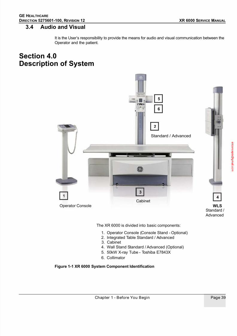
7/24/2019 GE XR6000 X-Ray - Service Manual
http://slidepdf.com/reader/full/ge-xr6000-x-ray-service-manual 39/421
GE HEALTHCARE
DIRECTION 5275601-100, REVISION 12 XR 6000 SERVICE MANUAL
Chapter 1 - Before You Begin Page 39
3.4 Audio and Visual
It is the User’s responsibility to provide the means for audio and visual communication between the
Operator and the patient.
Section 4.0
Description of System
Figure 1-1 XR 6000 System Component Identification
1
5
Operator Console
The XR 6000 is divided into basic components:
1. Operator Console (Console Stand - Optional)
2. Integrated Table Standard / Advanced
4. Wall Stand Standard / Advanced (Optional)
5. 50kW X-ray Tube - Toshiba E7843X
6. Collimator
6
3. Cabinet
4
Standard /
Advanced
WLS
Standard / Advanced
2
3
Cabinet
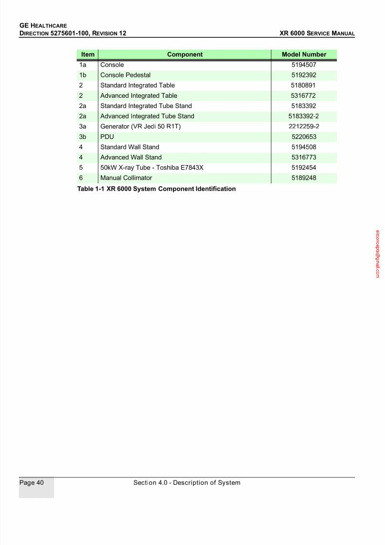
7/24/2019 GE XR6000 X-Ray - Service Manual
http://slidepdf.com/reader/full/ge-xr6000-x-ray-service-manual 40/421
GE HEALTHCARE
DIRECTION 5275601-100, REVISION 12 XR 6000 SERVICE MANUAL
Page 40 Section 4.0 - Description of System
Item Component Model Number
1a Console 5194507
1b Console Pedestal 5192392
2 Standard Integrated Table 5180891
2 Advanced Integrated Table 5316772
2a Standard Integrated Tube Stand 5183392
2a Advanced Integrated Tube Stand 5183392-2
3a Generator (VR Jedi 50 R1T) 2212259-2
3b PDU 5220653
4 Standard Wall Stand 5194508
4 Advanced Wall Stand 5316773
5 50kW X-ray Tube - Toshiba E7843X 5192454
6 Manual Collimator 5189248
Table 1-1 XR 6000 System Component Identification

7/24/2019 GE XR6000 X-Ray - Service Manual
http://slidepdf.com/reader/full/ge-xr6000-x-ray-service-manual 41/421
GE HEALTHCARE
DIRECTION 5275601-100, REVISION 12 XR 6000 SERVICE MANUAL
Chapter 2 - Physical Installation Page 41
Chapter 2 - Physical Installation
Installation is broken into two primary tasks: mechanical and electrical. Mechanical tasks focus on the physical aspects
of hardware assembly, equipment positioning, and cabling. Electrical tasks are performed when system power is
applied.
The primary tasks are designed to be performed in sequence. Follow the sequence of tasks describe for each primary
task in Section 1.0 that follow.
Section 1.0
System Installation Guide
1 Complete Pre-Installation Checklist People Required: 1 Minutes to Complete: 10
Fill out the Pre-Installation Checklist to confirm completion of pre-install activities before beginning the
installation process.
2 Receive and Inventory System People Required: 1 Minutes to Complete: 10
Inventory equipment & report discrepancies immediately.
Collect Product Locator Cards and store in a secure location.
Plan route and transport equipment to room.
3 Install Table People Required: 2 Minutes to Complete: 140
Remove table from shipping container.
Position and install table according to site plans & drawings, and secure.
Remove tube stand from shipping container.
Install tube stand.
Install X-ray tube.
Install control box and collimator.
Counterweight balance.
Install cassette tray(Not needed for advanced Integrate table).
Install ion chamber and grid (optional).
Electrical connections.
Install cabinet tray.Table top installation and leveling.
4 Install System Console People Required: 1 Minutes to Complete: 15
Position and install system console according to site plans & drawings, and secure.
5 Collimator Alignment People Required: 1 Minutes to Complete: 30
Power up system.
Collimator alignment.
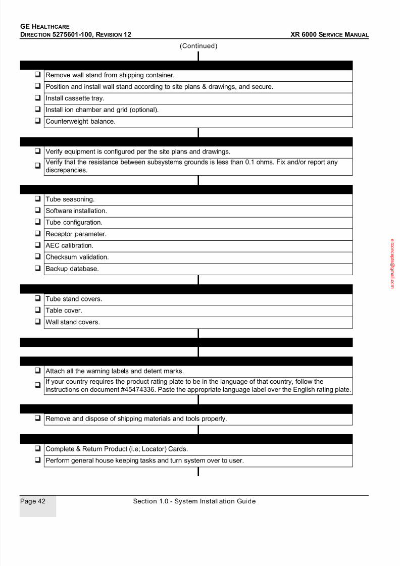
7/24/2019 GE XR6000 X-Ray - Service Manual
http://slidepdf.com/reader/full/ge-xr6000-x-ray-service-manual 42/421
GE HEALTHCARE
DIRECTION 5275601-100, REVISION 12 XR 6000 SERVICE MANUAL
Page 42 Section 1.0 - System Installation Guide
6 Install Wall Stand People Required: 2 Minutes to Complete: 50
Remove wall stand from shipping container.
Position and install wall stand according to site plans & drawings, and secure.
Install cassette tray.
Install ion chamber and grid (optional).
Counterweight balance.
7 Equipment and Personnel Readiness People Required: 1 Minutes to Complete: 10
Verify equipment is configured per the site plans and drawings.
Verify that the resistance between subsystems grounds is less than 0.1 ohms. Fix and/or report any
discrepancies.
8 Configure and Calibrate System People Required: 1 Minutes to Complete: 215
Tube seasoning.
Software installation.
Tube configuration.
Receptor parameter.
AEC calibration.
Checksum validation.
Backup database.
9 Install Subsystem Protective Covers People Required: 1 Minutes to Complete: 30
Tube stand covers.
Table cover.
Wall stand covers.
10 System Checks People Required: 1 Minutes to Complete: 30
11 Attach Warning Labels and Rating Plates People Required: 1 Minutes to Complete: 15
Attach all the warning labels and detent marks.
If your country requires the product rating plate to be in the language of that country, follow the
instructions on document #45474336. Paste the appropriate language label over the English rating plate.
12 Cleanup Site People Required: 1 Minutes to Complete: 20
Remove and dispose of shipping materials and tools properly.
13 Customer Turnover People Required: 1 Minutes to Complete: 10
Complete & Return Product (i.e; Locator) Cards.
Perform general house keeping tasks and turn system over to user.
(Continued)

7/24/2019 GE XR6000 X-Ray - Service Manual
http://slidepdf.com/reader/full/ge-xr6000-x-ray-service-manual 43/421
GE HEALTHCARE
DIRECTION 5275601-100, REVISION 12 XR 6000 SERVICE MANUAL
Chapter 2 - Physical Installation Page 43
Lead is used in this system to provide required radiation shielding, such as in tube, collimator,
please pay attention and do not touch it directly.
14 Complete Installation Checklist People Required: 1 Minutes to Complete: 10
Field Engineer to fill out installation checklist at completion of installation.
(Continued)

7/24/2019 GE XR6000 X-Ray - Service Manual
http://slidepdf.com/reader/full/ge-xr6000-x-ray-service-manual 44/421
GE HEALTHCARE
DIRECTION 5275601-100, REVISION 12 XR 6000 SERVICE MANUAL
Page 44 Section 2.0 - Installation Checklist
Section 2.0 Installation Checklist
Pre-Installation Checklist
Delivery Date: Sales Person:
Customer: FDO No.: Room #
Equipment:
Physical Requirements of Site Completed
1.) Room size adequate for intended equipment configuration?
2.) Floor is strong enough for intended equipment and mounting methods
approved?
3.) Delivery route accommodates all intended equipment?
4.) Radiation physicist consulted?
5.) Necessary alterations made to circumvent obstructions?
6.) Modifications to room finished?
7.) Supports, platforms materials been provided?
8.) Support structures installed for floor and wall mounted equipment?
9.) Has floor been modified for cable ducts?
10.) Electrical service in place – at the ratings specified in pre-installation
documentation?
11.) Power available to operate power tools?
12.) All non-electrical lines (air, water, oxygen, vacuum) installed?
Interconnections Completed
1.) Signal cable, power and grounding plans produced?
2.) Necessary interconnection hardware, such as junction boxes, conduit or
raceways, and fittings provided?
3.) Interconnection hardware installed?
4.) Flexible, stranded wire provided for System input power connection?
5.) System “feeder” power cables pulled and sufficient length available at
disconnect box for connections?
6.) Interconnecting cables continuity checked, and labeled?
7.) All high voltage cable lengths verified?
8.) Interface information available for equipment?

7/24/2019 GE XR6000 X-Ray - Service Manual
http://slidepdf.com/reader/full/ge-xr6000-x-ray-service-manual 45/421
GE HEALTHCARE
DIRECTION 5275601-100, REVISION 12 XR 6000 SERVICE MANUAL
Chapter 2 - Physical Installation Page 45
General Completed
1.) Walls and floor clear of all obstructions?
2.) Walls finished?
3.) Finished floor installed?
4.) Room lights installed?
5.) Dust-creating work completed?
6.) Old equipment within room removed?
7.) Component positions clearly marked on floor?
8.) Space available to store equipment?
9.) Lock on door, or locked room available?
10.) Have all fire/safety inspections for occupancy been completed?
11.) Send completed checklist to the GE Healthcare installation team.
Comments:
Inspection Date(s):
Installation Project Manager Signature

7/24/2019 GE XR6000 X-Ray - Service Manual
http://slidepdf.com/reader/full/ge-xr6000-x-ray-service-manual 46/421
GE HEALTHCARE
DIRECTION 5275601-100, REVISION 12 XR 6000 SERVICE MANUAL
Page 46 Section 2.0 - Installation Checklist
Installation ChecklistPurpose: Installation checklist to confirm that all critical installation steps have been completed.
Item # Item Sign Off
1.) Power and ground cables connected and tightened:
Power cables (how many?, where?)
Ground cables (how many?, where?)
2.) All signal cables connected and tightened.
3.) Cable shield clamps installed and tightened (how many?, where?).
4.) All mounting bolts installed and tightened (floor and wall).
5.) Control room cables properly dressed.
6.) All covers installed.
7.) Room cleaned.
8.) Product locator cards collected.
9.) Missing components and/or options:
10.) List of any installation drawing deviations (all deviations should be signed by customer
and reviewed by the installation specialist).
11.) Packing materials disposed of.
12.) Dollies and crates returned:
Positioner table / Standard Wall Stand dolly
13.) Have all calibrations been completed?
14.) Have purchased options been installed/enabled/configured?
15.) All appropriate regulatory labels installed:
X-ray tube focal spot
Warning labels
Rating plates
16.) InSite checkout completed?
17.) Have functional checks been completed?
18.) Are all covers installed?
19.) Have all protective tape/coverings been removed?

7/24/2019 GE XR6000 X-Ray - Service Manual
http://slidepdf.com/reader/full/ge-xr6000-x-ray-service-manual 47/421
GE HEALTHCARE
DIRECTION 5275601-100, REVISION 12 XR 6000 SERVICE MANUAL
Chapter 2 - Physical Installation Page 47
Field Engineer Signature: ____________________________________
20.) Are there any cosmetic issues?
21.) Are there any system issues?
22.) Are there any functional limitations?
23.) Has system documentation (paper and CDROM) been given to the customer?
24.) Has local physics inspection been completed. Some states/sites may not allow use of
system for patients until this is done.
25.) Has backup of pristine system been performed? (Patient Data Base as well as total
system backup)
26.) Has Field Engineer completed all checklists:
Pre-Installation
Installation checklist
Item # Item Sign Off
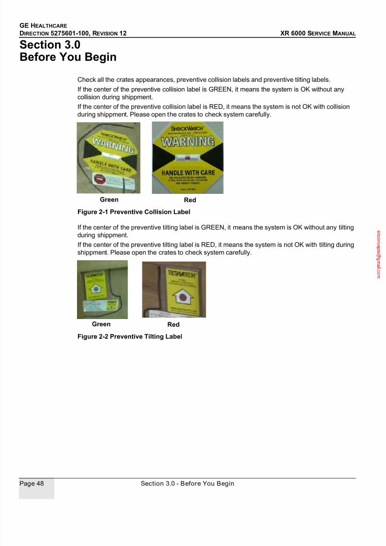
7/24/2019 GE XR6000 X-Ray - Service Manual
http://slidepdf.com/reader/full/ge-xr6000-x-ray-service-manual 48/421
GE HEALTHCARE
DIRECTION 5275601-100, REVISION 12 XR 6000 SERVICE MANUAL
Page 48 Section 3.0 - Before You Begin
Section 3.0 Before You Begin
Check all the crates appearances, preventive collision labels and preventive tilting labels.
If the center of the preventive collision label is GREEN, it means the system is OK without any
collision during shippment.
If the center of the preventive collision label is RED, it means the system is not OK with collision
during shippment. Please open the crates to check system carefully.
Figure 2-1 Preventive Collision Label
If the center of the preventive tilting label is GREEN, it means the system is OK without any tilting
during shippment.
If the center of the preventive tilting label is RED, it means the system is not OK with tilting during
shippment. Please open the crates to check system carefully.
Figure 2-2 Preventive Tilting Label
Green Red
Green Red
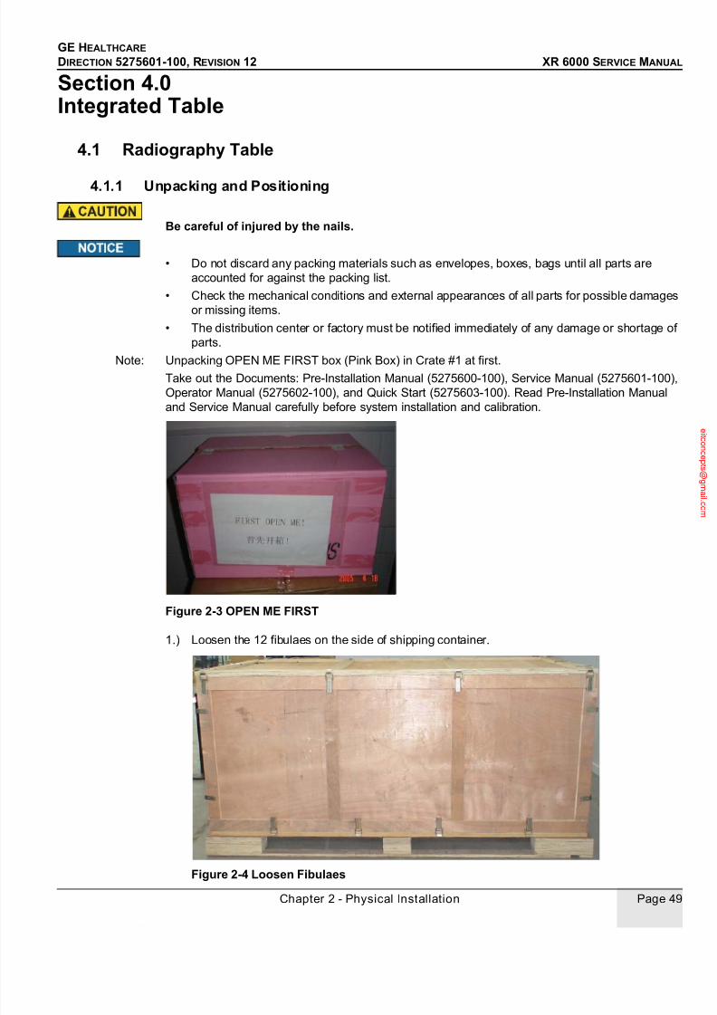
7/24/2019 GE XR6000 X-Ray - Service Manual
http://slidepdf.com/reader/full/ge-xr6000-x-ray-service-manual 49/421
GE HEALTHCARE
DIRECTION 5275601-100, REVISION 12 XR 6000 SERVICE MANUAL
Chapter 2 - Physical Installation Page 49
Section 4.0 Integrated Table
4.1 Radiography Table
4.1.1 Unpacking and Positioning
Be careful of injured by the nails.
• Do not discard any packing materials such as envelopes, boxes, bags until all parts are
accounted for against the packing list.
• Check the mechanical conditions and external appearances of all parts for possible damages
or missing items.
• The distribution center or factory must be notified immediately of any damage or shortage of
parts.
Note: Unpacking OPEN ME FIRST box (Pink Box) in Crate #1 at first.
Take out the Documents: Pre-Installation Manual (5275600-100), Service Manual (5275601-100),
Operator Manual (5275602-100), and Quick Start (5275603-100). Read Pre-Installation Manual
and Service Manual carefully before system installation and calibration.
Figure 2-3 OPEN ME FIRST
1.) Loosen the 12 fibulaes on the side of shipping container.
Figure 2-4 Loosen Fibulaes

7/24/2019 GE XR6000 X-Ray - Service Manual
http://slidepdf.com/reader/full/ge-xr6000-x-ray-service-manual 50/421
GE HEALTHCARE
DIRECTION 5275601-100, REVISION 12 XR 6000 SERVICE MANUAL
Page 50 Section 4.0 - Integrated Table
Note: To remove the side shipping container successfully, fix the fibulaes after loosen them.
2.) Remove the side shipping container, and table top is bound on it. See Figure 2-5.
Figure 2-5 Table Crate with Side Removed
3.) Loosen the remaining fibulaes, and remove the top and other sides of shipping containers
together. See Figure 2-6 and Figure 2-7.
Figure 2-6 Loosen Remaining Fibulaes
Side Shipping Container with Table Top

7/24/2019 GE XR6000 X-Ray - Service Manual
http://slidepdf.com/reader/full/ge-xr6000-x-ray-service-manual 51/421
GE HEALTHCARE
DIRECTION 5275601-100, REVISION 12 XR 6000 SERVICE MANUAL
Chapter 2 - Physical Installation Page 51
Figure 2-7 Remove Crate Top and Sides
4.) Remove the protective covering.
Figure 2-8 Remove the Protective Covering
5.) Take out all the boxes from the crate.

7/24/2019 GE XR6000 X-Ray - Service Manual
http://slidepdf.com/reader/full/ge-xr6000-x-ray-service-manual 52/421
GE HEALTHCARE
DIRECTION 5275601-100, REVISION 12 XR 6000 SERVICE MANUAL
Page 52 Section 4.0 - Integrated Table
Figure 2-9 Take Out All the Boxes
6.) Unpack the ramps and dolly.
Figure 2-10 Unpack Ramps and Dolly
7.) Place the ramps.
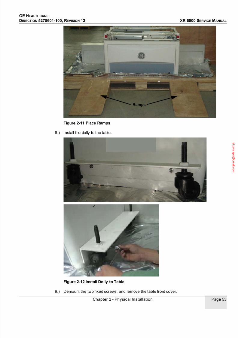
7/24/2019 GE XR6000 X-Ray - Service Manual
http://slidepdf.com/reader/full/ge-xr6000-x-ray-service-manual 53/421
GE HEALTHCARE
DIRECTION 5275601-100, REVISION 12 XR 6000 SERVICE MANUAL
Chapter 2 - Physical Installation Page 53
Figure 2-11 Place Ramps
8.) Install the dolly to the table.
Figure 2-12 Install Dolly to Table
9.) Demount the two fixed screws, and remove the table front cover.
Ramps
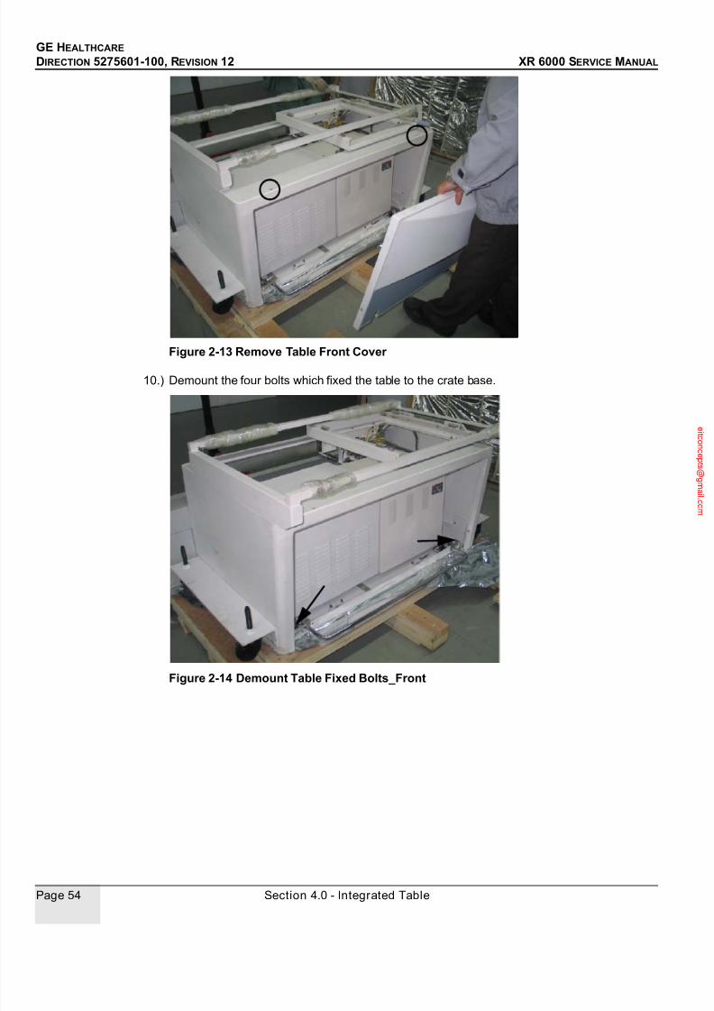
7/24/2019 GE XR6000 X-Ray - Service Manual
http://slidepdf.com/reader/full/ge-xr6000-x-ray-service-manual 54/421
GE HEALTHCARE
DIRECTION 5275601-100, REVISION 12 XR 6000 SERVICE MANUAL
Page 54 Section 4.0 - Integrated Table
Figure 2-13 Remove Table Front Cover
10.) Demount the four bolts which fixed the table to the crate base.
Figure 2-14 Demount Table Fixed Bolts_Front

7/24/2019 GE XR6000 X-Ray - Service Manual
http://slidepdf.com/reader/full/ge-xr6000-x-ray-service-manual 55/421
GE HEALTHCARE
DIRECTION 5275601-100, REVISION 12 XR 6000 SERVICE MANUAL
Chapter 2 - Physical Installation Page 55
Figure 2-15 Demount Table Fixed Bolts_Rear
11.) Adjust caster bolts to lower the casters down the table base level. See Figure 2-16.
Figure 2-16 Lower Casters
12.) Pull the table down the ramp and to the field.
DO NOT put your feet under the table base.
Be careful of being injured by integrated table because of the heavy weight.
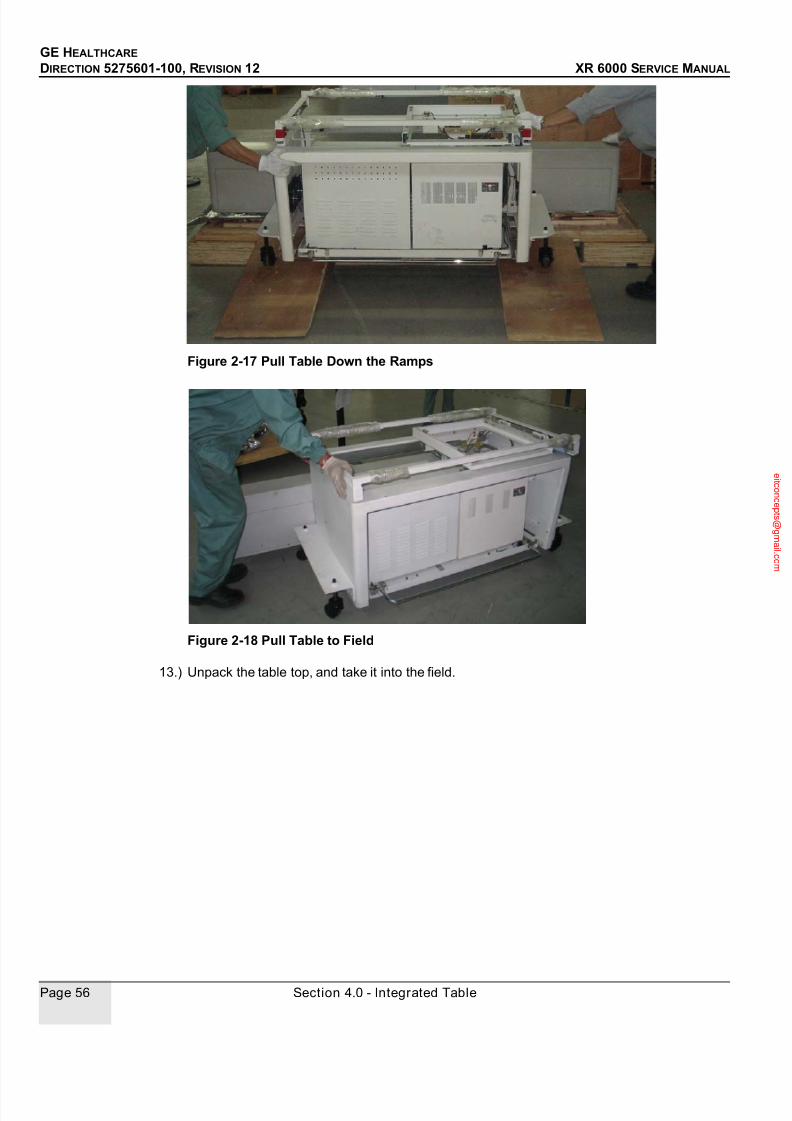
7/24/2019 GE XR6000 X-Ray - Service Manual
http://slidepdf.com/reader/full/ge-xr6000-x-ray-service-manual 56/421
GE HEALTHCARE
DIRECTION 5275601-100, REVISION 12 XR 6000 SERVICE MANUAL
Page 56 Section 4.0 - Integrated Table
Figure 2-17 Pull Table Down the Ramps
Figure 2-18 Pull Table to Field
13.) Unpack the table top, and take it into the field.

7/24/2019 GE XR6000 X-Ray - Service Manual
http://slidepdf.com/reader/full/ge-xr6000-x-ray-service-manual 57/421
GE HEALTHCARE
DIRECTION 5275601-100, REVISION 12 XR 6000 SERVICE MANUAL
Chapter 2 - Physical Installation Page 57
Figure 2-19 Cut Belts
Figure 2-20 Remove Protective Covering
Figure 2-21 Take to Field
4.1.2 Installation
1.) Refer to the room layout in Pre-Installation Manual (5275600-100), confirm the location of the
table with the operator, make marks and move the table away.
2.) Drill four holes at the marks, and then clean the holes of all dust and chips.

7/24/2019 GE XR6000 X-Ray - Service Manual
http://slidepdf.com/reader/full/ge-xr6000-x-ray-service-manual 58/421
GE HEALTHCARE
DIRECTION 5275601-100, REVISION 12 XR 6000 SERVICE MANUAL
Page 58 Section 4.0 - Integrated Table
Note: Please use 10 drill.
Figure 2-22 Drill Holes
3.) Move the table, let the mounting holes on the table align the holes in the floor, and adjust caster
bolts to upper the casters above the table base level.
Figure 2-23 Upper Casters4.) Demount the casters.
5.) Insert the supplied four M10 anchors and washers, and hammer the anchors into the holes.
6.) Level the table base as necessary with shims, and place the shims close to the anchors.
Figure 2-24 Table Base Level

7/24/2019 GE XR6000 X-Ray - Service Manual
http://slidepdf.com/reader/full/ge-xr6000-x-ray-service-manual 59/421
GE HEALTHCARE
DIRECTION 5275601-100, REVISION 12 XR 6000 SERVICE MANUAL
Chapter 2 - Physical Installation Page 59
7.) Tighten the anchors to fix the table to the floor.
8.) Demount the three table stop plates (RED color) in the table frame.
Figure 2-25 Demount Table Stop Plates
9.) Take out all the cables inside the tube stand rail, and route the cables.
Note: Suggest to route the cables from the table food end.
Figure 2-26 Route Cables
10.) Demount the cabinet tray with two screws each side and pull it out.
Be careful! DO NOT damage the cables.
TableHeadEnd
TableFootEnd

7/24/2019 GE XR6000 X-Ray - Service Manual
http://slidepdf.com/reader/full/ge-xr6000-x-ray-service-manual 60/421
GE HEALTHCARE
DIRECTION 5275601-100, REVISION 12 XR 6000 SERVICE MANUAL
Page 60 Section 4.0 - Integrated Table
Figure 2-27 Demount Cabinet Tray
Note: Pull the center of the foot pedal.
Figure 2-28 Pull Out Cabinet Tray
11.) Demount generator cover with four screws and PDU cover with two screws, and put them
aside.
Pull Here

7/24/2019 GE XR6000 X-Ray - Service Manual
http://slidepdf.com/reader/full/ge-xr6000-x-ray-service-manual 61/421
GE HEALTHCARE
DIRECTION 5275601-100, REVISION 12 XR 6000 SERVICE MANUAL
Chapter 2 - Physical Installation Page 61
Figure 2-29 Demount Covers

7/24/2019 GE XR6000 X-Ray - Service Manual
http://slidepdf.com/reader/full/ge-xr6000-x-ray-service-manual 62/421
GE HEALTHCARE
DIRECTION 5275601-100, REVISION 12 XR 6000 SERVICE MANUAL
Page 62 Section 4.0 - Integrated Table
4.2 Tube Stand
4.2.1 Unpacking
Be careful of injured by the nails.
• Do not discard any packing materials such as envelopes, boxes, bags until all parts are
accounted for against the packing list.
• Check the mechanical conditions and external appearances of all parts for possible damages
or missing items.
• The distribution center or factory must be notified immediately of any damage or shortage of
parts.
1.) Loosen all the 6 fibulaes, and remove the top and sides of shipping containers together. See
Figure 2-30.
Figure 2-30 Loosen Fibulaes and Remove Crate

7/24/2019 GE XR6000 X-Ray - Service Manual
http://slidepdf.com/reader/full/ge-xr6000-x-ray-service-manual 63/421
GE HEALTHCARE
DIRECTION 5275601-100, REVISION 12 XR 6000 SERVICE MANUAL
Chapter 2 - Physical Installation Page 63
2.) Take out the covers.
3.) Remove the two fixed plates with two bolts each.
Figure 2-31 Remove Fixed Plates
4.) Remove the protective covering.

7/24/2019 GE XR6000 X-Ray - Service Manual
http://slidepdf.com/reader/full/ge-xr6000-x-ray-service-manual 64/421
GE HEALTHCARE
DIRECTION 5275601-100, REVISION 12 XR 6000 SERVICE MANUAL
Page 64 Section 4.0 - Integrated Table
Figure 2-32 Remove Protective Covering
4.2.2 Installation
1.) Demount the rubber bumper and leveling bolt on one side of the tube stand rail.
Note: Suggest to install the tube stand from the table head end (if the cables are routed from the table
food end).
2.) Raise the tube stand.
TableHeadEnd

7/24/2019 GE XR6000 X-Ray - Service Manual
http://slidepdf.com/reader/full/ge-xr6000-x-ray-service-manual 65/421
GE HEALTHCARE
DIRECTION 5275601-100, REVISION 12 XR 6000 SERVICE MANUAL
Chapter 2 - Physical Installation Page 65
Figure 2-33 Raise the Tube Stand
3.) Slide the tube stand into the rail.
Figure 2-34 Install the Tube Stand
4.) Install the rubber bumper and screw back.
5.) Demount the RED counterweight lock screw on the back of tube stand.

7/24/2019 GE XR6000 X-Ray - Service Manual
http://slidepdf.com/reader/full/ge-xr6000-x-ray-service-manual 66/421
GE HEALTHCARE
DIRECTION 5275601-100, REVISION 12 XR 6000 SERVICE MANUAL
Page 66 Section 4.0 - Integrated Table
Figure 2-35 Demount Lock Screw
6.) Demount tube stand back cover, connect the tube stand cables (TM1-XS105 cable 5193103,
No1 cable 5197244, and Grouding cables 5193106 / 5193107), and remount the back cover.
Figure 2-36 Connect Tube Stand Cables
Part No. Part Name END1 Label From END2 label To
5193103 TM1-XS105 Cable XP105 5197244’s XS105 TM1-1 Table TM1 1
TM1-2 Table TM1 2
TM1-3 Table TM1 3
TM1-4 Table TM1 4
XS106 5220569’s XP106
5139106 Table Grounding Cable 2 PE1 PE1 PE2 PE2
5193107 Table Grounding Cable 3 PE2 PE2 PE3 PE3
5139106/5139107
5139103 - XS106
5139103 - XP105

7/24/2019 GE XR6000 X-Ray - Service Manual
http://slidepdf.com/reader/full/ge-xr6000-x-ray-service-manual 67/421
GE HEALTHCARE
DIRECTION 5275601-100, REVISION 12 XR 6000 SERVICE MANUAL
Chapter 2 - Physical Installation Page 67
Figure 2-37 Mount Back Cover
7.) Mount the cable routing plate to the tube stand.
Figure 2-38 Cable Routing in Plate
Note: DO NOT twist the cables when mounting the plate.

7/24/2019 GE XR6000 X-Ray - Service Manual
http://slidepdf.com/reader/full/ge-xr6000-x-ray-service-manual 68/421
GE HEALTHCARE
DIRECTION 5275601-100, REVISION 12 XR 6000 SERVICE MANUAL
Page 68 Section 4.0 - Integrated Table
Figure 2-39 Mount Cable Routing Plate
8.) Press the tube arm to the appropriate position that are easy to install the tube and collimator,
and insert the carriage fixed bolt again to fix the carriage.
Figure 2-40 Fix the Carriage

7/24/2019 GE XR6000 X-Ray - Service Manual
http://slidepdf.com/reader/full/ge-xr6000-x-ray-service-manual 69/421
GE HEALTHCARE
DIRECTION 5275601-100, REVISION 12 XR 6000 SERVICE MANUAL
Chapter 2 - Physical Installation Page 69
4.3 X-Ray Tube
Note: For tube instruction, refer to related contents contained in the related specifications.
Check calibration due date of Torque wrench and shelf-life of Loctite before usage.
In order to ensure to meet the security needs, apply Loctite 242(or 243) to the three screws
and tighten these 3 screws to 24 N-m (17.7 lbs-ft) with the torque wrench is the step must be
performed, while installation and FRU replace.
1.) Loosen the three bolts on the tube arm, put the tube forks into the tube stand arm.
2.) Apply Loctite 242(or 243) to the three screws assembling the tube fork with tube stand arm
3.) Tighten these three bolts to 24 N-m (17.7 lbs-ft) with the torque wrench
4.) Mount the cable supporting plate
Figure 2-41 Install Tube Fork and Supporting Plate
Note: Insert the tube fork by referring to the mark.
Figure 2-42 Mark
5.) Loosen the four screws of the upper clamp of tube fork, and remove the upper clamp of tube
fork.
To prevent the clamps from any impact. In case impact occurred, it should be verified that the
clamp has enough strength before installation.
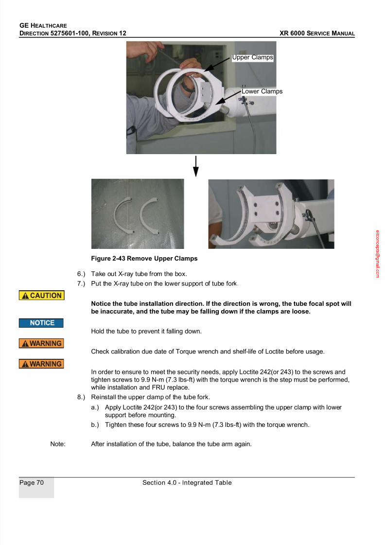
7/24/2019 GE XR6000 X-Ray - Service Manual
http://slidepdf.com/reader/full/ge-xr6000-x-ray-service-manual 70/421
GE HEALTHCARE
DIRECTION 5275601-100, REVISION 12 XR 6000 SERVICE MANUAL
Page 70 Section 4.0 - Integrated Table
Figure 2-43 Remove Upper Clamps
6.) Take out X-ray tube from the box.
7.) Put the X-ray tube on the lower support of tube fork.
Notice the tube installation direction. If the direction is wrong, the tube focal spot willbe inaccurate, and the tube may be falling down if the clamps are loose.
Hold the tube to prevent it falling down.
Check calibration due date of Torque wrench and shelf-life of Loctite before usage.
In order to ensure to meet the security needs, apply Loctite 242(or 243) to the screws and
tighten screws to 9.9 N-m (7.3 lbs-ft) with the torque wrench is the step must be performed,while installation and FRU replace.
8.) Reinstall the upper clamp of the tube fork.
a.) Apply Loctite 242(or 243) to the four screws assembling the upper clamp with lower
support before mounting.
b.) Tighten these four screws to 9.9 N-m (7.3 lbs-ft) with the torque wrench.
Note: After installation of the tube, balance the tube arm again.
Upper Clamps
Lower Clamps
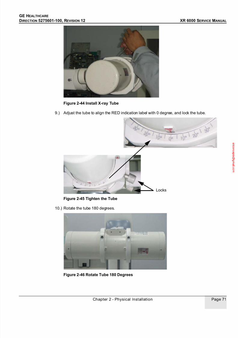
7/24/2019 GE XR6000 X-Ray - Service Manual
http://slidepdf.com/reader/full/ge-xr6000-x-ray-service-manual 71/421
GE HEALTHCARE
DIRECTION 5275601-100, REVISION 12 XR 6000 SERVICE MANUAL
Chapter 2 - Physical Installation Page 71
Figure 2-44 Install X-ray Tube
9.) Adjust the tube to align the RED indication label with 0 degree, and lock the tube.
Figure 2-45 Tighten the Tube
10.) Rotate the tube 180 degrees.
Figure 2-46 Rotate Tube 180 Degrees
Locks

7/24/2019 GE XR6000 X-Ray - Service Manual
http://slidepdf.com/reader/full/ge-xr6000-x-ray-service-manual 72/421
GE HEALTHCARE
DIRECTION 5275601-100, REVISION 12 XR 6000 SERVICE MANUAL
Page 72 Section 4.0 - Integrated Table
4.4 Control Box and Collimator
1.) Demount the two stop plates and take out the collimator flange.
Figure 2-47 Demount Stop Plates and Take Out Flange
Suggest to demount the two stop plates totally, but NOT only loosen them. Or the stopplates will crash the glass window during collimator installation.
Control Box
Handle
Control Box
Cover
Spacer
Collimator
Stop
Plates
Collimator
Flange

7/24/2019 GE XR6000 X-Ray - Service Manual
http://slidepdf.com/reader/full/ge-xr6000-x-ray-service-manual 73/421
GE HEALTHCARE
DIRECTION 5275601-100, REVISION 12 XR 6000 SERVICE MANUAL
Chapter 2 - Physical Installation Page 73
Figure 2-48 Wrong Way
Figure 2-49 Correct Way
2.) Demount the four mounting screws on the tube.
Figure 2-50 Demount Mounting Screws
Glass Window

7/24/2019 GE XR6000 X-Ray - Service Manual
http://slidepdf.com/reader/full/ge-xr6000-x-ray-service-manual 74/421
GE HEALTHCARE
DIRECTION 5275601-100, REVISION 12 XR 6000 SERVICE MANUAL
Page 74 Section 4.0 - Integrated Table
Check calibration due date of Torque wrench and shelf-life of Loctite before usage.
In order to ensure to meet the security needs, apply Loctite 242(or 243) to the screws and
tighten bolts to 9.9 N-m (7.3 lbs-ft) with the torque wrench is the step must be performed, while
installation and FRU replace.
3.) Put the spacer and control box handle between the collimator flange and the tube, apply
Loctite 242 (or 243) to the four screws, tighten to 9.9 N-m (7.3lbs-ft) with the torque wrench.
Note: Please install the collimator flange according to the marks on the x-ray tube.
Figure 2-51 Mark
Figure 2-52 Mount Control Box Handle
Collimator Flange
Control Handle
Daub to the
screw thread
Drop into
the hole
Spacer

7/24/2019 GE XR6000 X-Ray - Service Manual
http://slidepdf.com/reader/full/ge-xr6000-x-ray-service-manual 75/421
GE HEALTHCARE
DIRECTION 5275601-100, REVISION 12 XR 6000 SERVICE MANUAL
Chapter 2 - Physical Installation Page 75
Check calibration due date of Torque wrench and shelf-life of Loctite before usage.
In order to ensure to meet the security needs, The Loctite 242(or 243) to the bolts and tighten
bolts to 9.9 N-m (7.3 lbs-ft) with the torque wrench is the step must be performed, while
installation and FRU replace.
4.) Mount collimator onto the collimator adapter using the two stop plates, apply Loctite 242 (or
243) to the four screws, tighten to 9.9 N-m (7.3lbs-ft) with the torque wrench.
Figure 2-53 Mount Collimator
5.) Rotate tube back.
Figure 2-54 Rotate Tube Back
6.) Route the cable through cable supporting bracket to the tube side.
Note: DO NOT fix the cables on supporting bracket or plate before the cable connections on tube
side.
7.) Prior to the connection of the high-voltage cables, remove the old silicone compound on the
plug surfaces with clean dry cloth and check to verify there are as cracks, flaws, or traces of
creeping discharge on the surfaces.

7/24/2019 GE XR6000 X-Ray - Service Manual
http://slidepdf.com/reader/full/ge-xr6000-x-ray-service-manual 76/421
GE HEALTHCARE
DIRECTION 5275601-100, REVISION 12 XR 6000 SERVICE MANUAL
Page 76 Section 4.0 - Integrated Table
Note: When the traces of creeping discharge are found, be sure to replace the defective parts.
Grinding off the traces only will not be effective.
8.) Coat the tip of the cable plugs with the silicone compound about five to seven grams, that is,
to the extent the tip is hidden under the heaped up compound. At this time, the side of the cable
plug should be greased.
Figure 2-55 Coating with Silicone Compound
9.) Remove the cap covered the socket of the tube housing and wipe the inside softly with a clean
dry cloth. DO NOT use any chlorinated solvents to clean any parts.
10.) Connect the anode and cathode HV cables (2269002-5) to the X-ray tube.
Check the polarity of HV cables carefully, and DO NOT connect the two HV cablesreversely.
Connect the HV cables in the correct polarity with sufficient care not to produceclearance between the cable plug flange and the cable socket at the insertion of theplugs. Presence of such clearance or incomplete silicone compound coating will causecreeping discharge and normal operation of tube will be disturbed.
HV Cable Socket HV Cable
+ (ANODE) +
- (CATHODE) -
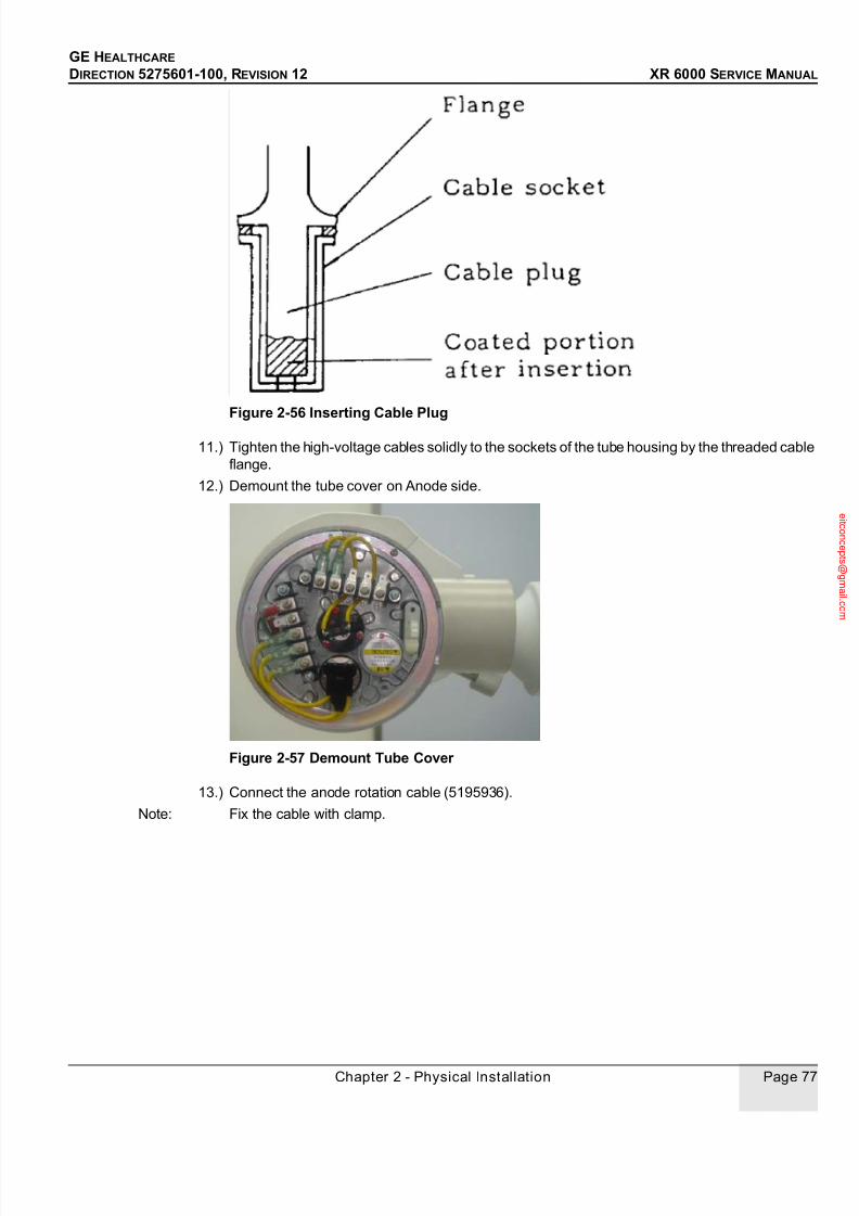
7/24/2019 GE XR6000 X-Ray - Service Manual
http://slidepdf.com/reader/full/ge-xr6000-x-ray-service-manual 77/421
GE HEALTHCARE
DIRECTION 5275601-100, REVISION 12 XR 6000 SERVICE MANUAL
Chapter 2 - Physical Installation Page 77
Figure 2-56 Inserting Cable Plug
11.) Tighten the high-voltage cables solidly to the sockets of the tube housing by the threaded cable
flange.
12.) Demount the tube cover on Anode side.
Figure 2-57 Demount Tube Cover
13.) Connect the anode rotation cable (5195936).
Note: Fix the cable with clamp.

7/24/2019 GE XR6000 X-Ray - Service Manual
http://slidepdf.com/reader/full/ge-xr6000-x-ray-service-manual 78/421
GE HEALTHCARE
DIRECTION 5275601-100, REVISION 12 XR 6000 SERVICE MANUAL
Page 78 Section 4.0 - Integrated Table
Figure 2-58 Anode Rotation Cable Conections
14.) Remount the tube cover.
Figure 2-59 Remount Tube Cover
15.) Connect the control box cables to the connecting plate, fix the plate onto control box, ty-rap
the cables and fix with a cupule, and mount the control box cover.
Tube HV Tank Color
1 C White
2 M Black
3 A Red
SW SW Brown
SW SW Yellow
E E Green
Part No. Part Name END1
Label
From END2 Label To
5197242 MC7 Cable XP102 Tube Fork
5197245's XS102
MC7+ MC7+
MC7- MC7-
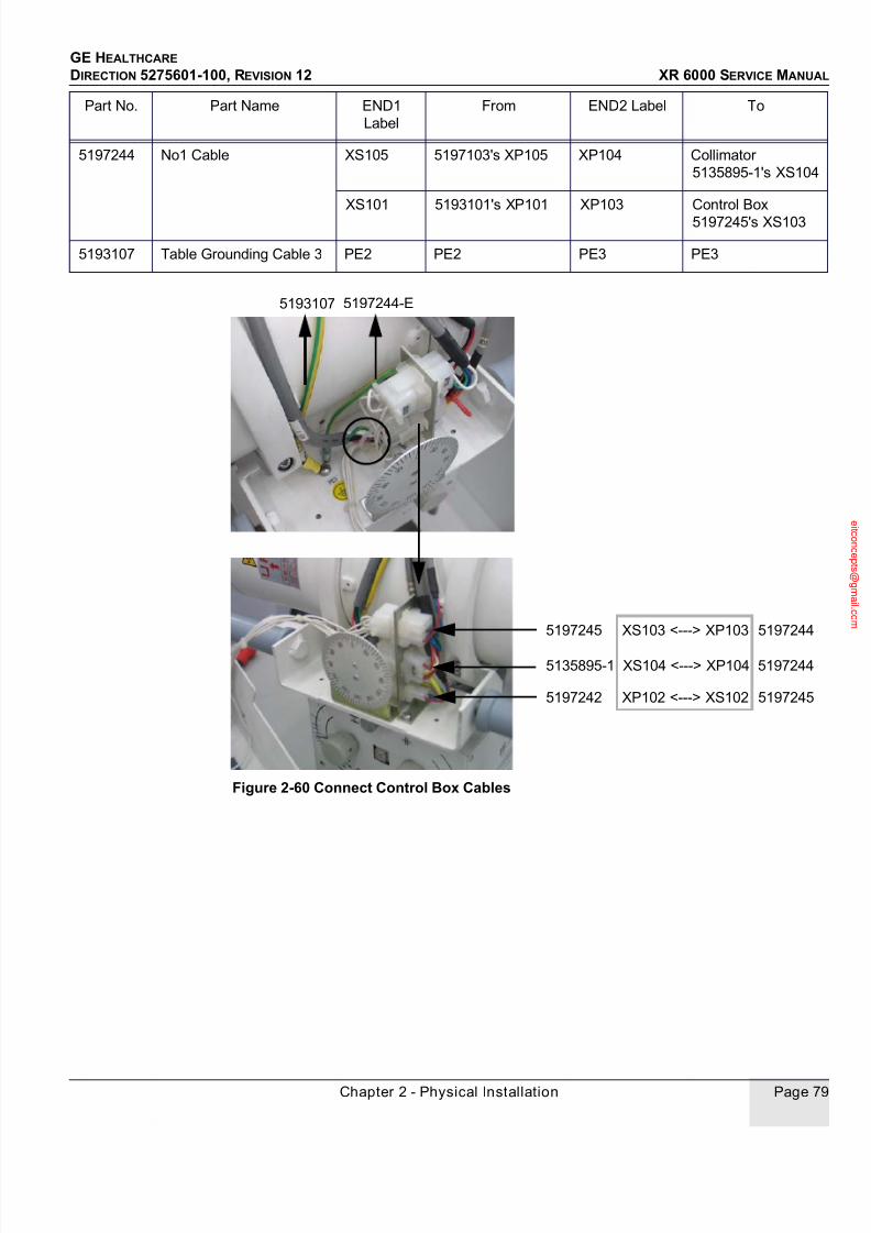
7/24/2019 GE XR6000 X-Ray - Service Manual
http://slidepdf.com/reader/full/ge-xr6000-x-ray-service-manual 79/421
GE HEALTHCARE
DIRECTION 5275601-100, REVISION 12 XR 6000 SERVICE MANUAL
Chapter 2 - Physical Installation Page 79
Figure 2-60 Connect Control Box Cables
5197244 No1 Cable XS105 5197103's XP105 XP104 Collimator
5135895-1's XS104
XP103 Control Box
5197245's XS103
XS101 5193101's XP101
5193107 Table Grounding Cable 3 PE2 PE2 PE3 PE3
Part No. Part Name END1
Label
From END2 Label To
5193107
5197242 XP102 <---> XS102 5197245
5135895-1 XS104 <---> XP104 5197244
5197245 XS103 <---> XP103 5197244
5197244-E

7/24/2019 GE XR6000 X-Ray - Service Manual
http://slidepdf.com/reader/full/ge-xr6000-x-ray-service-manual 80/421
GE HEALTHCARE
DIRECTION 5275601-100, REVISION 12 XR 6000 SERVICE MANUAL
Page 80 Section 4.0 - Integrated Table
Figure 2-61 Install Control Box Cover
16.) Install the cable supporting plate, route and ty-rap the cables, and fix them onto the plate.
Be careful of the cable moving range, and make sure the cable will not be damaged during
tube movement.
a. Loosen the handles.
b. Install thecontrol box cover.
c. Tighten the handles.

7/24/2019 GE XR6000 X-Ray - Service Manual
http://slidepdf.com/reader/full/ge-xr6000-x-ray-service-manual 81/421
GE HEALTHCARE
DIRECTION 5275601-100, REVISION 12 XR 6000 SERVICE MANUAL
Chapter 2 - Physical Installation Page 81
Figure 2-62 Fix Cables onto Supporting Plate
17.) Mount the cable supporting bracket onto the back of the tube stand, put the cables onto the
supporting bracket, but DO NOT fix the cables.
Figure 2-63 Mount Cable Supporting Bracket
18.) Connect the No1 cable (5197244).
Supporting Plate
Fix
Part No. Part Name END1
Label
From END2 Label To
5197244 No1 Cable XS105 5197103's XP105 XP104 Collimator
5135895-1's XS104
XP103 Control Box
5197245's XS103
XS101 5193101's XP101
5193101 MC6 Cable MC6 MC6 XP101 5197244’s XS101
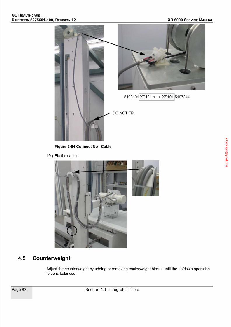
7/24/2019 GE XR6000 X-Ray - Service Manual
http://slidepdf.com/reader/full/ge-xr6000-x-ray-service-manual 82/421
GE HEALTHCARE
DIRECTION 5275601-100, REVISION 12 XR 6000 SERVICE MANUAL
Page 82 Section 4.0 - Integrated Table
Figure 2-64 Connect No1 Cable
19.) Fix the cables.
4.5 Counterweight
Adjust the counterweight by adding or removing couterweight blocks until the up/down operation
force is balanced.
DO NOT FIX
5193101 XP101 <---> XS101 5197244
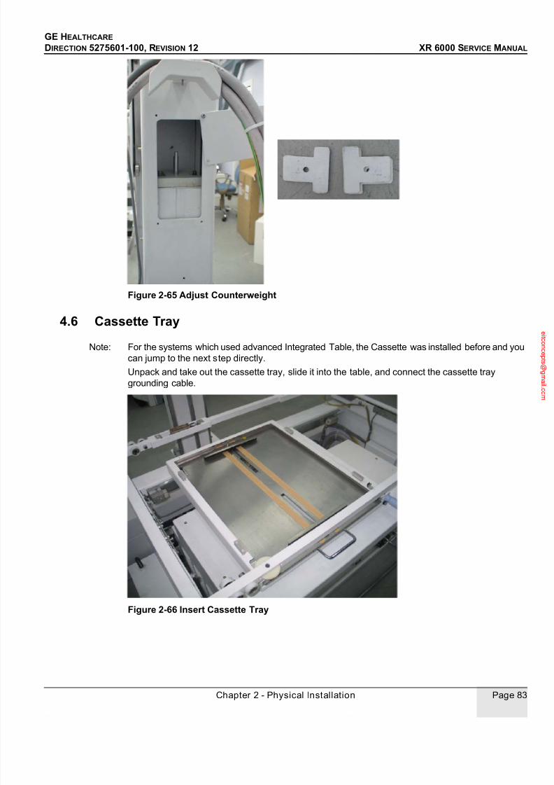
7/24/2019 GE XR6000 X-Ray - Service Manual
http://slidepdf.com/reader/full/ge-xr6000-x-ray-service-manual 83/421
GE HEALTHCARE
DIRECTION 5275601-100, REVISION 12 XR 6000 SERVICE MANUAL
Chapter 2 - Physical Installation Page 83
Figure 2-65 Adjust Counterweight
4.6 Cassette Tray
Note: For the systems which used advanced Integrated Table, the Cassette was installed before and you
can jump to the next step directly.
Unpack and take out the cassette tray, slide it into the table, and connect the cassette tray
grounding cable.
Figure 2-66 Insert Cassette Tray
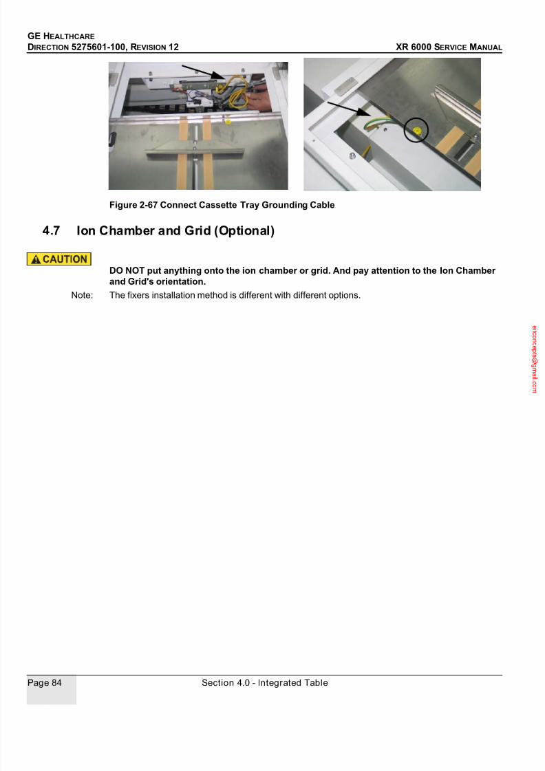
7/24/2019 GE XR6000 X-Ray - Service Manual
http://slidepdf.com/reader/full/ge-xr6000-x-ray-service-manual 84/421
GE HEALTHCARE
DIRECTION 5275601-100, REVISION 12 XR 6000 SERVICE MANUAL
Page 84 Section 4.0 - Integrated Table
Figure 2-67 Connect Cassette Tray Grounding Cable
4.7 Ion Chamber and Grid (Optional)
DO NOT put anything onto the ion chamber or grid. And pay attention to the Ion Chamberand Grid's orientation.
Note: The fixers installation method is different with different options.

7/24/2019 GE XR6000 X-Ray - Service Manual
http://slidepdf.com/reader/full/ge-xr6000-x-ray-service-manual 85/421
GE HEALTHCARE
DIRECTION 5275601-100, REVISION 12 XR 6000 SERVICE MANUAL
Chapter 2 - Physical Installation Page 85
4.7.1 Install both Ion Chamber and Grid for system with standard Integrated table
1.) Demount the cassette tray side cover and two of the four fixers, and loosen the other two.
Figure 2-68 Demount the Cover and Fixers
2.) Install the ion chamber and grid, connect table ion chamber (5167409) and 4 m cable
(5166493), and install the cassette tray side cover back.
Cassette TraySide Cover
Fixer Limit
Position
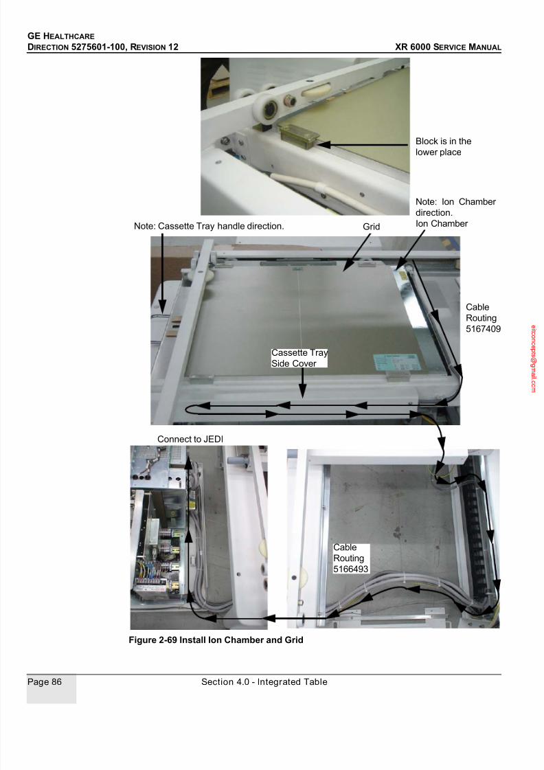
7/24/2019 GE XR6000 X-Ray - Service Manual
http://slidepdf.com/reader/full/ge-xr6000-x-ray-service-manual 86/421
GE HEALTHCARE
DIRECTION 5275601-100, REVISION 12 XR 6000 SERVICE MANUAL
Page 86 Section 4.0 - Integrated Table
Figure 2-69 Install Ion Chamber and Grid
Block is in the
lower place
Note: Ion Chamber
direction.
Ion Chamber Grid
Cassette Tray
Side Cover
Cable
Routing
5167409
Cable
Routing
5166493
Connect to JEDI
Note: Cassette Tray handle direction.

7/24/2019 GE XR6000 X-Ray - Service Manual
http://slidepdf.com/reader/full/ge-xr6000-x-ray-service-manual 87/421
GE HEALTHCARE
DIRECTION 5275601-100, REVISION 12 XR 6000 SERVICE MANUAL
Chapter 2 - Physical Installation Page 87
Figure 2-70 Table Ion Chamber to JEDI
AEC1

7/24/2019 GE XR6000 X-Ray - Service Manual
http://slidepdf.com/reader/full/ge-xr6000-x-ray-service-manual 88/421
GE HEALTHCARE
DIRECTION 5275601-100, REVISION 12 XR 6000 SERVICE MANUAL
Page 88 Section 4.0 - Integrated Table
4.7.2 Install the Grid Only for system with standard Integrated table
1.) Demount the four fixers.
Figure 2-71 Demount the Fixers
2.) Install the grid.
Fixer Limit
Position

7/24/2019 GE XR6000 X-Ray - Service Manual
http://slidepdf.com/reader/full/ge-xr6000-x-ray-service-manual 89/421
GE HEALTHCARE
DIRECTION 5275601-100, REVISION 12 XR 6000 SERVICE MANUAL
Chapter 2 - Physical Installation Page 89
Figure 2-72 Install Grid
4.7.3 Install the Ion Chamber and Grid for system with advanced Integrated tableFor the system with advanced integrated table, the grid was oscillate grid. The installatation should
be done as steps below:
Block is in the
upper place

7/24/2019 GE XR6000 X-Ray - Service Manual
http://slidepdf.com/reader/full/ge-xr6000-x-ray-service-manual 90/421
GE HEALTHCARE
DIRECTION 5275601-100, REVISION 12 XR 6000 SERVICE MANUAL
Page 90 Section 4.0 - Integrated Table
1.) Remove the cover A by remove the five screws as fig 2-73 shown.
Figure 2-73 Remove the cover A
2.) Loosen the four screws marked with circle in Fig 2-74 which were used to tighten the ion
chamber.
Figure 2-74 Loosen the four screws
3.) Insert the ionion chamber to the holder as Fig 2-75 shown. Please be care for the orientation
Cover Ascrew used to mount the cover
the four screws used to tighten theion chamber. The ion chamber was
used to help to show the screw’s position.

7/24/2019 GE XR6000 X-Ray - Service Manual
http://slidepdf.com/reader/full/ge-xr6000-x-ray-service-manual 91/421
GE HEALTHCARE
DIRECTION 5275601-100, REVISION 12 XR 6000 SERVICE MANUAL
Chapter 2 - Physical Installation Page 91
of the grid.
Figure 2-75 Insert the ion Chamber to the holder
4.) Adjust the position of the ion chamber as these steps:
1.) Make the rod perpendicular.
Figure 2-76 Make the rod perpendicular
2.) Use the cover A dismounted before as ruler to mark the center of the rectangle used to
hold the grid, then adjust the position of ion chamber to make the center of the ion
Make the rod perpendicular
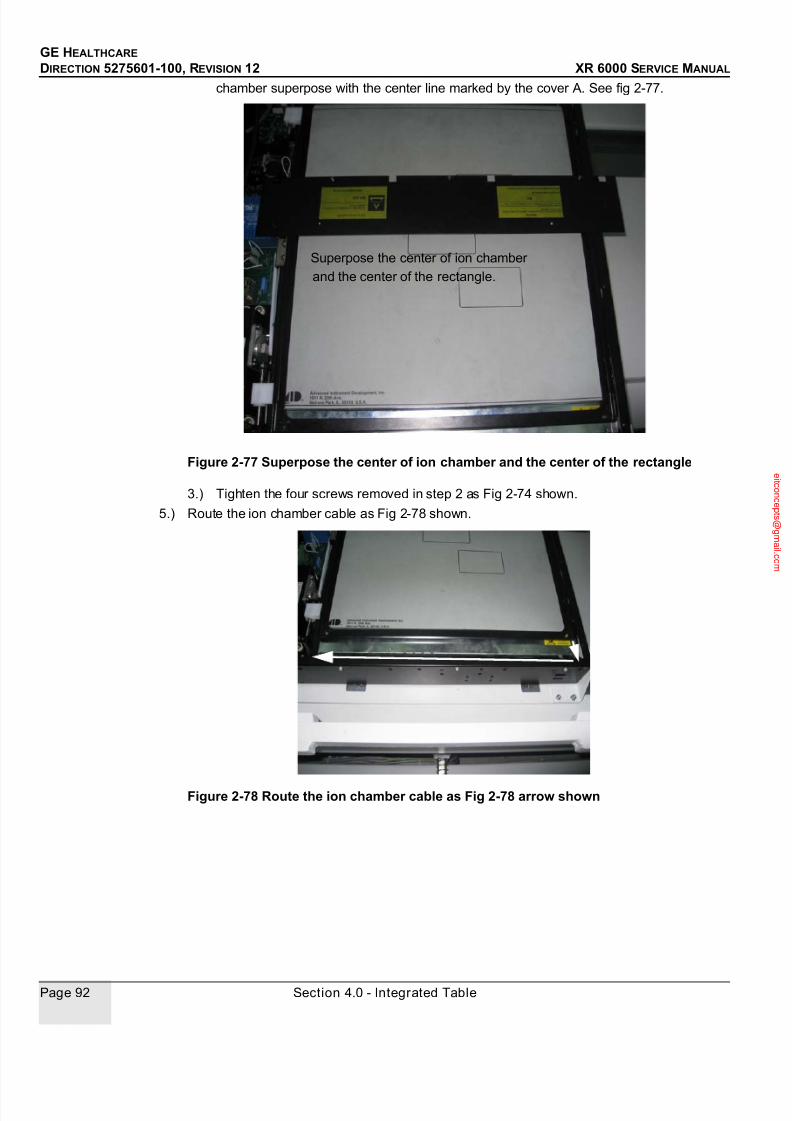
7/24/2019 GE XR6000 X-Ray - Service Manual
http://slidepdf.com/reader/full/ge-xr6000-x-ray-service-manual 92/421
GE HEALTHCARE
DIRECTION 5275601-100, REVISION 12 XR 6000 SERVICE MANUAL
Page 92 Section 4.0 - Integrated Table
chamber superpose with the center line marked by the cover A. See fig 2-77.
Figure 2-77 Superpose the center of ion chamber and the center of the rectangle
3.) Tighten the four screws removed in step 2 as Fig 2-74 shown.
5.) Route the ion chamber cable as Fig 2-78 shown.
Figure 2-78 Route the ion chamber cable as Fig 2-78 arrow shown
Superpose the center of ion chamber
and the center of the rectangle.
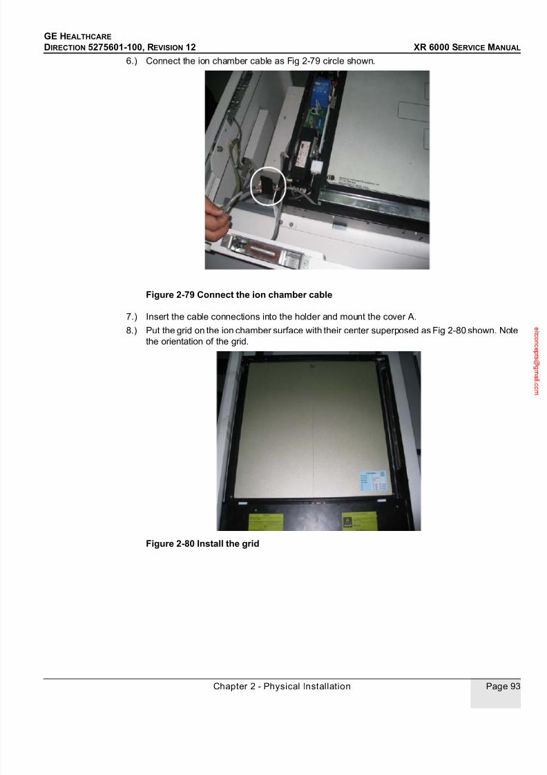
7/24/2019 GE XR6000 X-Ray - Service Manual
http://slidepdf.com/reader/full/ge-xr6000-x-ray-service-manual 93/421
GE HEALTHCARE
DIRECTION 5275601-100, REVISION 12 XR 6000 SERVICE MANUAL
Chapter 2 - Physical Installation Page 93
6.) Connect the ion chamber cable as Fig 2-79 circle shown.
Figure 2-79 Connect the ion chamber cable
7.) Insert the cable connections into the holder and mount the cover A.
8.) Put the grid on the ion chamber surface with their center superposed as Fig 2-80 shown. Note
the orientation of the grid.
Figure 2-80 Install the grid

7/24/2019 GE XR6000 X-Ray - Service Manual
http://slidepdf.com/reader/full/ge-xr6000-x-ray-service-manual 94/421
GE HEALTHCARE
DIRECTION 5275601-100, REVISION 12 XR 6000 SERVICE MANUAL
Page 94 Section 4.0 - Integrated Table
9.) Fix the grid with four fixers.
Figure 2-81 Fix the grid with four fixers
4.8 Electrical Connections
For details, please refer to Chapter 10 - Schematics, Chapter 11 - MIS Chart, and Pre-Installation
Manual (5275600-100).
1.) Connect and route System Power Cable (hospital provide).
Figure 2-82 Connect and Route System Power Cable
2.) Connect and Xray-on Light (pin 4, 6) and Room Door interlock (pin 1, 2) Cables (hospital
Fixer

7/24/2019 GE XR6000 X-Ray - Service Manual
http://slidepdf.com/reader/full/ge-xr6000-x-ray-service-manual 95/421
GE HEALTHCARE
DIRECTION 5275601-100, REVISION 12 XR 6000 SERVICE MANUAL
Chapter 2 - Physical Installation Page 95
provide). For details, please refer to Room Power Supply in Chapter 4 of Pre-Installation
Manual (5275600-100).
Figure 2-83 Connect Xray-on light and Room Door interlock Cables
3.) If wall stand ion chamber is ordered, connect and route the ion chamber 24 m cable (5166654)
and grounding cable (5193110) to JEDI.
9
8
7
6
5
4
3
2
1
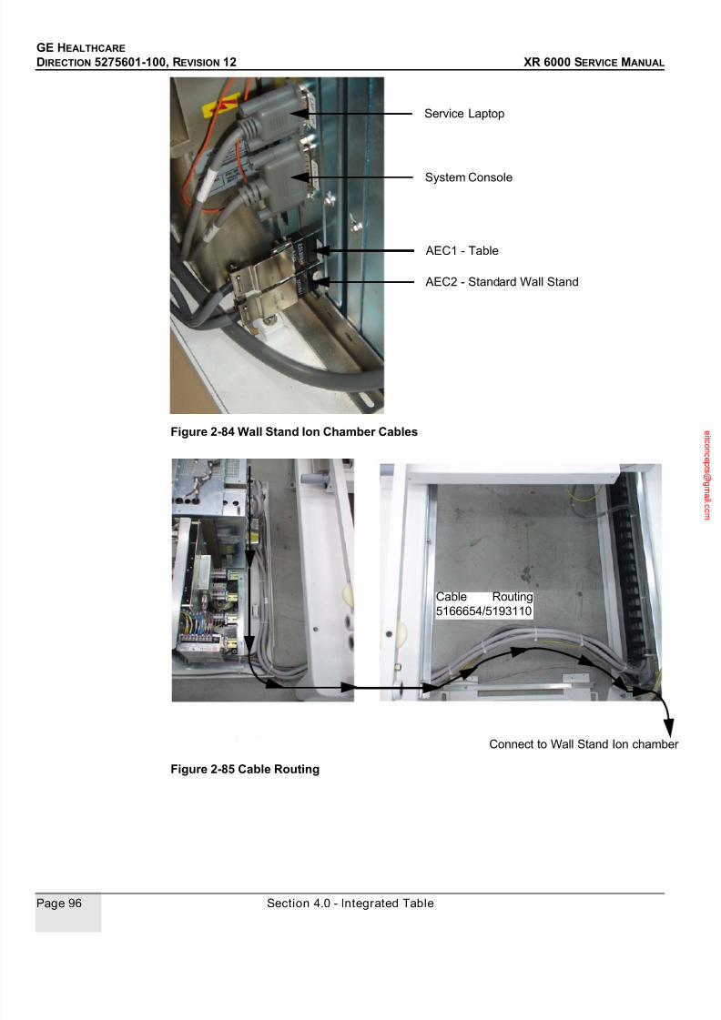
7/24/2019 GE XR6000 X-Ray - Service Manual
http://slidepdf.com/reader/full/ge-xr6000-x-ray-service-manual 96/421
GE HEALTHCARE
DIRECTION 5275601-100, REVISION 12 XR 6000 SERVICE MANUAL
Page 96 Section 4.0 - Integrated Table
Figure 2-84 Wall Stand Ion Chamber Cables
Figure 2-85 Cable Routing
Service Laptop
System Console
AEC1 - Table
AEC2 - Standard Wall Stand
Cable Routing
5166654/5193110
Connect to Wall Stand Ion chamber

7/24/2019 GE XR6000 X-Ray - Service Manual
http://slidepdf.com/reader/full/ge-xr6000-x-ray-service-manual 97/421
GE HEALTHCARE
DIRECTION 5275601-100, REVISION 12 XR 6000 SERVICE MANUAL
Chapter 2 - Physical Installation Page 97
4.9 Install Cabinet Tray
1.) Install generator and PDU covers, and push cabinet tray to under the table.
Figure 2-86 Install Generator and PDU Covers
2.) Fix the cabinet tray to the table base with two screws.
Figure 2-87 Install Cabinet Tray
Push Here

7/24/2019 GE XR6000 X-Ray - Service Manual
http://slidepdf.com/reader/full/ge-xr6000-x-ray-service-manual 98/421
GE HEALTHCARE
DIRECTION 5275601-100, REVISION 12 XR 6000 SERVICE MANUAL
Page 98 Section 4.0 - Integrated Table
4.10 Table Top Installation and Leveling
1.) Demount the stopper on one side of the table top, slide the table top onto the table base, and
remount the stopper.
Figure 2-88 Install the Table Top
2.) Check the table top leveling. If it is not level, loosen the mounting anchors, and adjust the
leveling bolts, then fix them with washers.
Figure 2-89 Adjust Leveling Bolts

7/24/2019 GE XR6000 X-Ray - Service Manual
http://slidepdf.com/reader/full/ge-xr6000-x-ray-service-manual 99/421
GE HEALTHCARE
DIRECTION 5275601-100, REVISION 12 XR 6000 SERVICE MANUAL
Chapter 2 - Physical Installation Page 99
Section 5.0 System Console
Route the console cables to the control room.
5.1 Without Console Stand
Connect and ty-rap the console cables. Position the system console to the location where the
operator can observe the patients conveniently.
Figure 2-90 Console Cable Connections
5.2 With Console Stand
1.) Assemble the console onto the console stand, and demount the rear cover.
Figure 2-91 Console Installation
Part No. Part NameSystemConsole
The Other End
5184620 Handswitch J1 Handswitch
5194292/5241079 RS232 Service Cable / ISP Download Cable J2 Service Laptop
5183903 Console Power Cable J3 PDU - TM3
5182354 JEDI Generator Communication Cable J4 PDU - J1

7/24/2019 GE XR6000 X-Ray - Service Manual
http://slidepdf.com/reader/full/ge-xr6000-x-ray-service-manual 100/421
GE HEALTHCARE
DIRECTION 5275601-100, REVISION 12 XR 6000 SERVICE MANUAL
Page 100 Section 5.0 - System Console
2.) Connect and ty-rap the console cables.
Figure 2-92 Console Cable Connections
3.) Demount console stand bottom cover with two screws. Confirm the location of the console with
the operator, make marks and move the console away.
Figure 2-93 Demount Bottom Cover
4.) Drill two holes at the marks, and then clean the holes of all dust and chips.Note: Please use 7 drill.
5.) Move the console, and let the mounting holes on the console foot panel align the holes in the
floor.
6.) Insert the supplied two M6 anchors and washers, and hammer the anchors into the holes.
7.) Tighten the anchors.
8.) Mount the bottom cover back.
Part No. Part NameSystemConsole The Other End
5184620 Handswitch J1 Handswitch
5194292/5241079 RS232 Service Cable / ISP Download Cable J2 Service Laptop
5183903 Console Power Cable J3 PDU - TM3
5182354 JEDI Generator Communication Cable J4 PDU - J1

7/24/2019 GE XR6000 X-Ray - Service Manual
http://slidepdf.com/reader/full/ge-xr6000-x-ray-service-manual 101/421
GE HEALTHCARE
DIRECTION 5275601-100, REVISION 12 XR 6000 SERVICE MANUAL
Chapter 2 - Physical Installation Page 101
Section 6.0 Collimator Alignment
1.) Power up the system. Check LEDs status. Refer to Chapter 4 - Functional Checks - 3.1
System Power Up.
2.) Move the tube to the lowest position above the table top, open collimator light, confirm thecenter of the light field projected by the collimator with an article, such as a screw.
Figure 2-94 Lowest SID
3.) Move the tube up to the highest position.
Figure 2-95 Highest SID
4.) Make sure the bias of the center is less than 3 mm, and make sure the collimator beam can
align the center point of the cassette tray handle.

7/24/2019 GE XR6000 X-Ray - Service Manual
http://slidepdf.com/reader/full/ge-xr6000-x-ray-service-manual 102/421
GE HEALTHCARE
DIRECTION 5275601-100, REVISION 12 XR 6000 SERVICE MANUAL
Page 102 Section 7.0 - DAP Meter Installation
Figure 2-96 Collimator Beam Align Cassette Tray Handle Center Point
5.) If the requirements above cannot be met, adjust the three screws on the tube fork to align the
collimator.
Figure 2-97 Align Collimator
Section 7.0DAP Meter Installation
Note: Do not touch the active area of the ionization chamber (1) with bared finger. It may degrade
the light transparency of the DAP meter.
Figure 2-98 DAP Meter
Procedures:
Collimatorbeam
Handle Center
Bias in less
than 3 mm

7/24/2019 GE XR6000 X-Ray - Service Manual
http://slidepdf.com/reader/full/ge-xr6000-x-ray-service-manual 103/421
GE HEALTHCARE
DIRECTION 5275601-100, REVISION 12 XR 6000 SERVICE MANUAL
Chapter 2 - Physical Installation Page 103
Note: Fix the cable inside the tube cover for the system which does not include the DAP meter.
1.) Installing the Chamber in the X-ray Unit
Slide the chamber into the middle level of accessory rails of the collimator till the detent is
reached.
Figure 2-99 Insert DAP Meter into the middle level of the collimator rail
2.) Connect the Chamber with system
The back side of the DAP meter includes a short cable with a round plastic plug connector(ODU: MediSnap, 4-pin). This includes the connections for the power supply.
Note: Please be aware that the connector cable from tube stand side is only for the use of connecting
the DAP meter.
Figure 2-100 Connect the DAP Meter to the 24V Power Supply
3.) Connect the other end of the connector to the 24V power supply of the PDU. Connection
diagram as below:
TURN OFF THE POWER BEFORE CONNECT/DISCONNECT THE CHAMBERDo not
connect/disconnect the chamber to/from the system when the power is turned on. It may
damage the electronics.
7/24/2019 GE XR6000 X-Ray - Service Manual
http://slidepdf.com/reader/full/ge-xr6000-x-ray-service-manual 104/421
GE HEALTHCARE
DIRECTION 5275601-100, REVISION 12 XR 6000 SERVICE MANUAL
Page 104 Section 7.0 - DAP Meter Installation
DO NOT PUT THE ADDITIONAL FILTER ABOVE THE CHAMBER
Do not put any filtration between chamber and the patient in the exam. It may cause the wrong
indication of DAP value.
4.) Switching the device on/ DAP meter ready for using
After DAP meter is well mounted to collimator and connected to system power supply, the
meter is switched on when system is powered on. The display unit responds with a brief signaltone and the following labels:
VACUDAP
Vx.xx
11111111
22222222
:
WAITING
0.00
The firmware version (Vx.xx) of the display unit is output first. The Power-On test in the
measuring chamber is then started and a display test is executed simultaneously. The displayunit waits for the result of the TEST function when the WAITING label is displayed. After the
successful conclusion of the power-on test, the meter is either in the Measuring function or an
error message is output. The measuring readiness is displayed by the measured value zero
(display: 0.00 or 0.0).
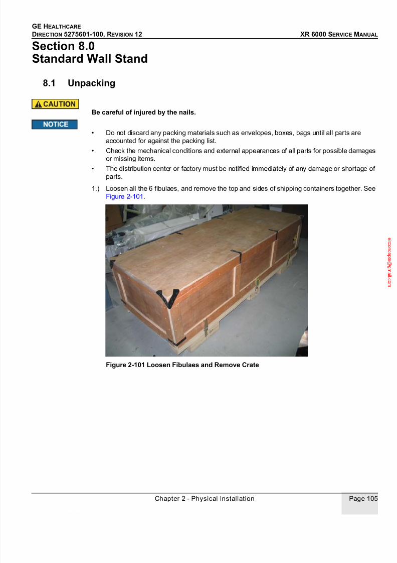
7/24/2019 GE XR6000 X-Ray - Service Manual
http://slidepdf.com/reader/full/ge-xr6000-x-ray-service-manual 105/421
GE HEALTHCARE
DIRECTION 5275601-100, REVISION 12 XR 6000 SERVICE MANUAL
Chapter 2 - Physical Installation Page 105
Section 8.0 Standard Wall Stand
8.1 Unpacking
Be careful of injured by the nails.
• Do not discard any packing materials such as envelopes, boxes, bags until all parts are
accounted for against the packing list.
• Check the mechanical conditions and external appearances of all parts for possible damages
or missing items.
• The distribution center or factory must be notified immediately of any damage or shortage of
parts.
1.) Loosen all the 6 fibulaes, and remove the top and sides of shipping containers together. See
Figure 2-101.
Figure 2-101 Loosen Fibulaes and Remove Crate

7/24/2019 GE XR6000 X-Ray - Service Manual
http://slidepdf.com/reader/full/ge-xr6000-x-ray-service-manual 106/421
GE HEALTHCARE
DIRECTION 5275601-100, REVISION 12 XR 6000 SERVICE MANUAL
Page 106 Section 8.0 - Standard Wall Stand
2.) Take out the covers.
3.) Remove the two fixed plates with two bolts each.
Figure 2-102 Remove Fixed Plates
4.) Remove the protective covering.

7/24/2019 GE XR6000 X-Ray - Service Manual
http://slidepdf.com/reader/full/ge-xr6000-x-ray-service-manual 107/421
GE HEALTHCARE
DIRECTION 5275601-100, REVISION 12 XR 6000 SERVICE MANUAL
Chapter 2 - Physical Installation Page 107
Figure 2-103 Remove Protective Covering
5.) Raise the wall stand.
Be careful of being injured by wall stand because of the heavy weight.
Figure 2-104 Raise Wall Stand

7/24/2019 GE XR6000 X-Ray - Service Manual
http://slidepdf.com/reader/full/ge-xr6000-x-ray-service-manual 108/421
GE HEALTHCARE
DIRECTION 5275601-100, REVISION 12 XR 6000 SERVICE MANUAL
Page 108 Section 8.0 - Standard Wall Stand
6.) Install dolly (5241044).
Figure 2-105 Dolly
7.) Adjust caster bolts to lower the casters down the wall stand base level. See Figure 2-106. Pull
wall stand into the field.
Figure 2-106 Lower Casters
8.2 Installation
1.) Refer to the room layout in Pre-Installation Manual (5275600-100), and confirm the location of
the wall stand with the operator. Move wall stand and its template to the location, adjust caster
Front
Rear
Front
Rear
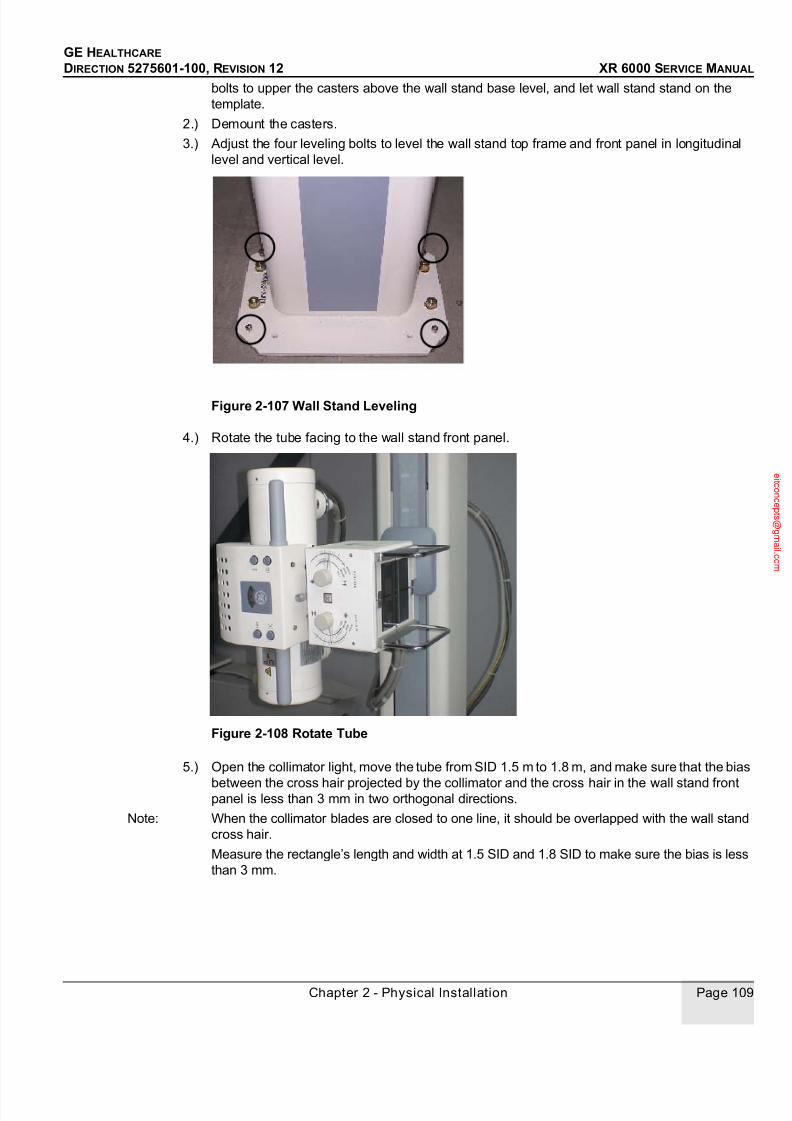
7/24/2019 GE XR6000 X-Ray - Service Manual
http://slidepdf.com/reader/full/ge-xr6000-x-ray-service-manual 109/421
GE HEALTHCARE
DIRECTION 5275601-100, REVISION 12 XR 6000 SERVICE MANUAL
Chapter 2 - Physical Installation Page 109
bolts to upper the casters above the wall stand base level, and let wall stand stand on the
template.
2.) Demount the casters.
3.) Adjust the four leveling bolts to level the wall stand top frame and front panel in longitudinal
level and vertical level.
Figure 2-107 Wall Stand Leveling
4.) Rotate the tube facing to the wall stand front panel.
Figure 2-108 Rotate Tube
5.) Open the collimator light, move the tube from SID 1.5 m to 1.8 m, and make sure that the bias
between the cross hair projected by the collimator and the cross hair in the wall stand frontpanel is less than 3 mm in two orthogonal directions.
Note: When the collimator blades are closed to one line, it should be overlapped with the wall stand
cross hair.
Measure the rectangle’s length and width at 1.5 SID and 1.8 SID to make sure the bias is less
than 3 mm.
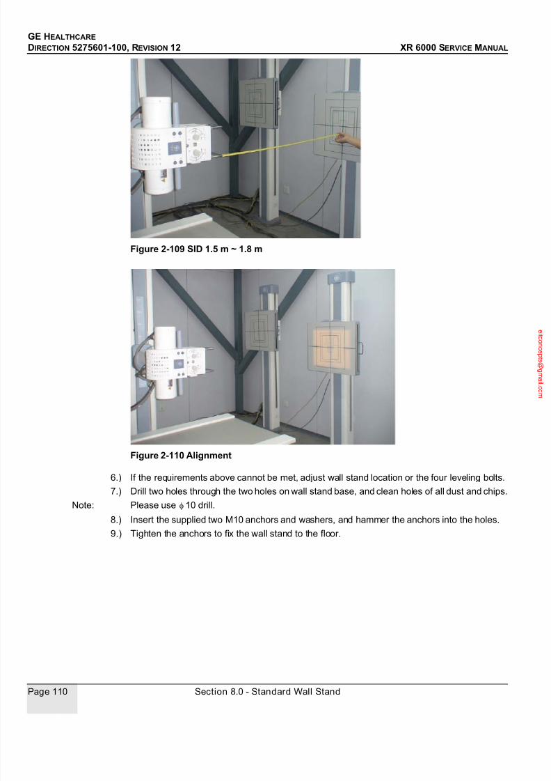
7/24/2019 GE XR6000 X-Ray - Service Manual
http://slidepdf.com/reader/full/ge-xr6000-x-ray-service-manual 110/421
GE HEALTHCARE
DIRECTION 5275601-100, REVISION 12 XR 6000 SERVICE MANUAL
Page 110 Section 8.0 - Standard Wall Stand
Figure 2-109 SID 1.5 m ~ 1.8 m
Figure 2-110 Alignment
6.) If the requirements above cannot be met, adjust wall stand location or the four leveling bolts.
7.) Drill two holes through the two holes on wall stand base, and clean holes of all dust and chips.
Note: Please use 10 drill.
8.) Insert the supplied two M10 anchors and washers, and hammer the anchors into the holes.
9.) Tighten the anchors to fix the wall stand to the floor.

7/24/2019 GE XR6000 X-Ray - Service Manual
http://slidepdf.com/reader/full/ge-xr6000-x-ray-service-manual 111/421
GE HEALTHCARE
DIRECTION 5275601-100, REVISION 12 XR 6000 SERVICE MANUAL
Chapter 2 - Physical Installation Page 111
Figure 2-111 Fix the Wall Stand
8.3 Cassette Tray
Unpack and take out the cassette tray, and slide it into the wall stand.
Figure 2-112 Insert Cassette Tray
8.4 Ion Chamber and Grid (Optional)
Note: The fixers installation method is different with different options. For details, please refer to section
4.7 Ion Chamber and Grid (Optional) in table installation.
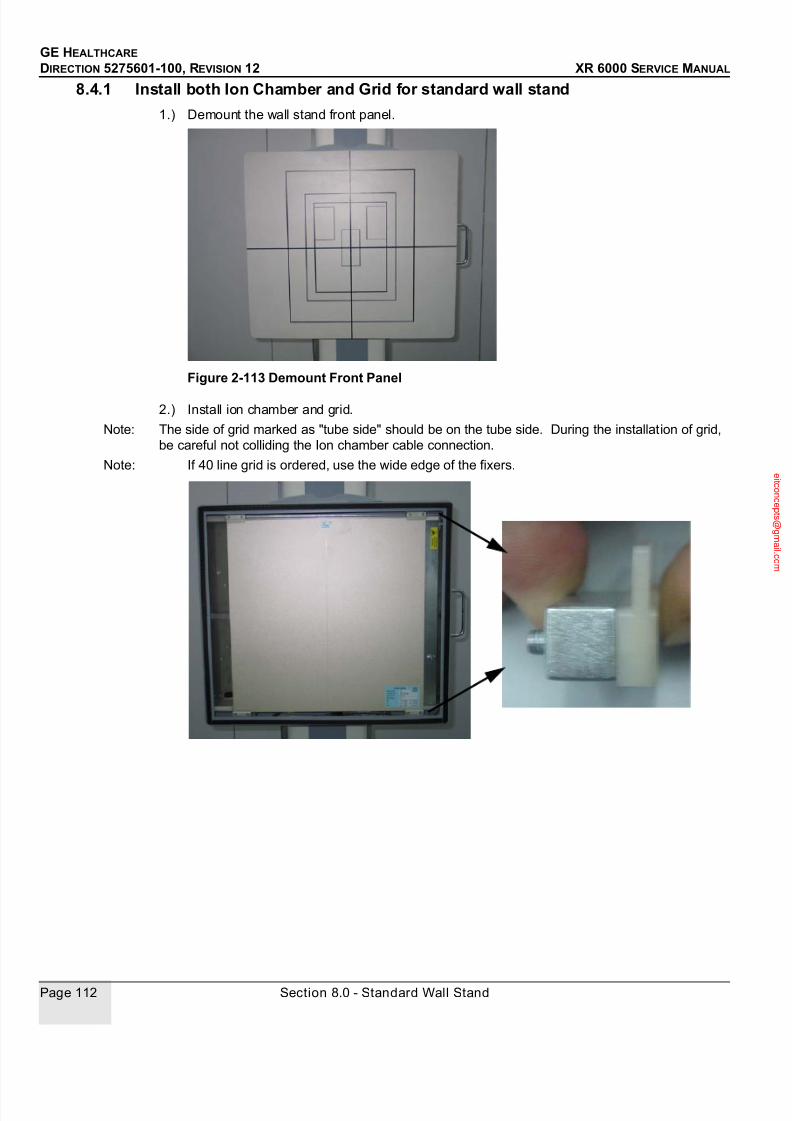
7/24/2019 GE XR6000 X-Ray - Service Manual
http://slidepdf.com/reader/full/ge-xr6000-x-ray-service-manual 112/421
GE HEALTHCARE
DIRECTION 5275601-100, REVISION 12 XR 6000 SERVICE MANUAL
Page 112 Section 8.0 - Standard Wall Stand
8.4.1 Install both Ion Chamber and Grid for standard wall stand
1.) Demount the wall stand front panel.
Figure 2-113 Demount Front Panel
2.) Install ion chamber and grid.
Note: The side of grid marked as "tube side" should be on the tube side. During the installation of grid,
be careful not colliding the Ion chamber cable connection.
Note: If 40 line grid is ordered, use the wide edge of the fixers.

7/24/2019 GE XR6000 X-Ray - Service Manual
http://slidepdf.com/reader/full/ge-xr6000-x-ray-service-manual 113/421
GE HEALTHCARE
DIRECTION 5275601-100, REVISION 12 XR 6000 SERVICE MANUAL
Chapter 2 - Physical Installation Page 113
Note: If 60 line or 78 line grid is ordered, use the wide edge of the fixers to the bottom and narrow
edge to the top.

7/24/2019 GE XR6000 X-Ray - Service Manual
http://slidepdf.com/reader/full/ge-xr6000-x-ray-service-manual 114/421
GE HEALTHCARE
DIRECTION 5275601-100, REVISION 12 XR 6000 SERVICE MANUAL
Page 114 Section 8.0 - Standard Wall Stand
3.) Connect and route the wall stand ion chamber cable.
Figure 2-114 Routing Ion Chamber Cables
Note: Ion Chamber direction.
Figure 2-115 Connect Ion Chamber Cables
4.) Remount the front panel.
From JEDI
Cable Routing
Ion Chamber Cable Connection
From back of Wall Stand
(5167409/5166654)
Ion Chamber Grounding Cable(5193110)
Cable Routing
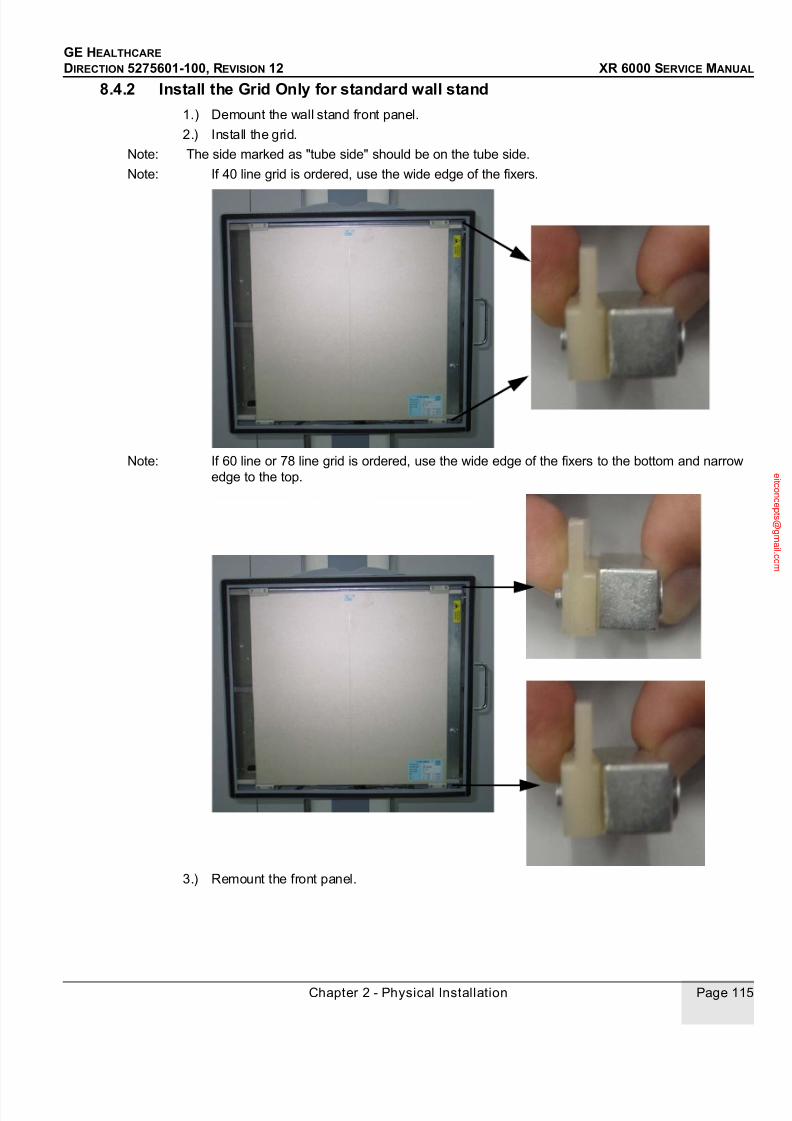
7/24/2019 GE XR6000 X-Ray - Service Manual
http://slidepdf.com/reader/full/ge-xr6000-x-ray-service-manual 115/421
GE HEALTHCARE
DIRECTION 5275601-100, REVISION 12 XR 6000 SERVICE MANUAL
Chapter 2 - Physical Installation Page 115
8.4.2 Install the Grid Only for standard wall stand
1.) Demount the wall stand front panel.
2.) Install the grid.
Note: The side marked as "tube side" should be on the tube side.
Note: If 40 line grid is ordered, use the wide edge of the fixers.
Note: If 60 line or 78 line grid is ordered, use the wide edge of the fixers to the bottom and narrow
edge to the top.
3.) Remount the front panel.

7/24/2019 GE XR6000 X-Ray - Service Manual
http://slidepdf.com/reader/full/ge-xr6000-x-ray-service-manual 116/421
GE HEALTHCARE
DIRECTION 5275601-100, REVISION 12 XR 6000 SERVICE MANUAL
Page 116 Section 8.0 - Standard Wall Stand
8.4.3 Install both Ion chamber and grid
1.) Demount the wall stand front panel
2.) Demount the cassette holder with the four screws marked with circle as the Fig below shown.
Figure 2-116 Demount the cassette holder
3.) Pull the the cassette holder out carefully and put it standing on ground.
4.) Demount the top cover of the cassette holder.
Figure 2-117 Remove the top cover of cassette holder
four screws fix the cassetteholder

7/24/2019 GE XR6000 X-Ray - Service Manual
http://slidepdf.com/reader/full/ge-xr6000-x-ray-service-manual 117/421
GE HEALTHCARE
DIRECTION 5275601-100, REVISION 12 XR 6000 SERVICE MANUAL
Chapter 2 - Physical Installation Page 117
5.) Loosen the four screws used to fix the ion chamber.
Figure 2-118 Loosen the four screws used to fix the ion chamber
6.) Demount the cover at the bottom of the front surface of the cassette holder.
7.) Insert the ion chamber in from the right side of the cassette hold at the orientation as the fig
shown below and route the cable according to the path the arrown shown.
Figure 2-119 Insert the ion chamber into the cassette holder and route the ion chambercable according to the path the arrow shown
8.) Lie down the cassette holder.
9.) Adjust the position of ion chamber to make sure that its center can superpose the center of
FOV as these steps:
Loosen the four screws used to fix the ion chamber.

7/24/2019 GE XR6000 X-Ray - Service Manual
http://slidepdf.com/reader/full/ge-xr6000-x-ray-service-manual 118/421
GE HEALTHCARE
DIRECTION 5275601-100, REVISION 12 XR 6000 SERVICE MANUAL
Page 118 Section 8.0 - Standard Wall Stand
1.) Make the rod perpendicular.
Figure 2-120 Make the rod perpendicular
2.) There is a screw hole on the center of the top side and bottom side of the rectangle
used to hold grid. Suppose the line across the two hole point was the FOV center and
we can use the cover dismounted at step 6 as a ruler to mark the line. Adjust the
position of ion chamber to make its center superpose the FOV’s center.
Figure 2-121 Make the center of ion chamber superpose the FOV’s center
10.) Tighten the four screws loosened at step 5 as Fig 2-115 to fix the ion chamber.
11.) Remount the top cover of the cassette holder.
12.) Remount the cassette holder to wall stand.
Make the rod perpendicular
the two screw holes can used to markthe FOV’s center line

7/24/2019 GE XR6000 X-Ray - Service Manual
http://slidepdf.com/reader/full/ge-xr6000-x-ray-service-manual 119/421
GE HEALTHCARE
DIRECTION 5275601-100, REVISION 12 XR 6000 SERVICE MANUAL
Chapter 2 - Physical Installation Page 119
13.) Connect the Ion chamber cable and ground cable as below Fig shown.
Figure 2-122 Connect the Ion chamber cable and ground cable
14.) Remount the cover at the bottom of the front surface of the cassette holder.
15.) Remount the wall stand front panel.
Connect the ground cable here
Connect the ion chamber cable here
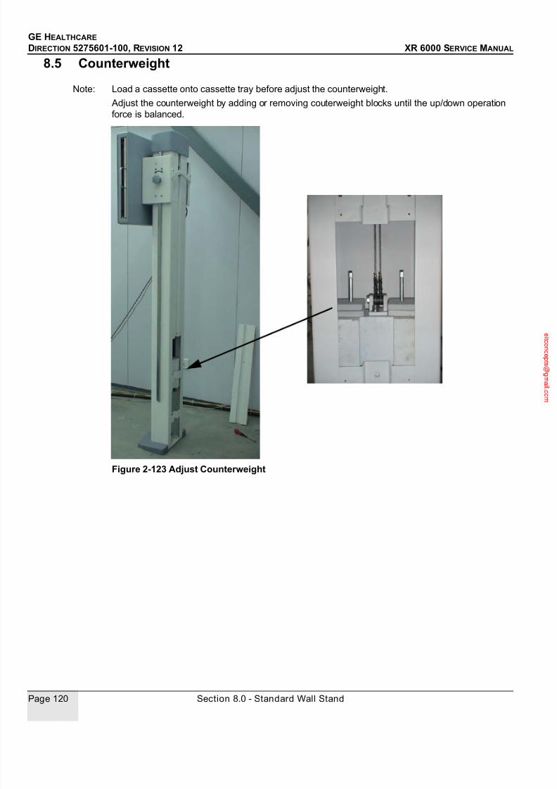
7/24/2019 GE XR6000 X-Ray - Service Manual
http://slidepdf.com/reader/full/ge-xr6000-x-ray-service-manual 120/421
GE HEALTHCARE
DIRECTION 5275601-100, REVISION 12 XR 6000 SERVICE MANUAL
Page 120 Section 8.0 - Standard Wall Stand
8.5 Counterweight
Note: Load a cassette onto cassette tray before adjust the counterweight.
Adjust the counterweight by adding or removing couterweight blocks until the up/down operation
force is balanced.
Figure 2-123 Adjust Counterweight

7/24/2019 GE XR6000 X-Ray - Service Manual
http://slidepdf.com/reader/full/ge-xr6000-x-ray-service-manual 121/421
GE HEALTHCARE
DIRECTION 5275601-100, REVISION 12 XR 6000 SERVICE MANUAL
Chapter 2 - Physical Installation Page 121
Section 9.0 Final Cover Installation
After system configuration and calibration, ty-rap all the cables, and install the protective covers.
9.1 Install Standard Tube Stand Covers
1
2
3

7/24/2019 GE XR6000 X-Ray - Service Manual
http://slidepdf.com/reader/full/ge-xr6000-x-ray-service-manual 122/421
GE HEALTHCARE
DIRECTION 5275601-100, REVISION 12 XR 6000 SERVICE MANUAL
Page 122 Section 9.0 - Final Cover Installation
1.) Loosen the screw on the tube arm protective cover.
Figure 2-124 Loosen the Protective Cover
2.) Insert SID ruler through the cover, and install the ruler.
Figure 2-125 Install SID Ruler
3.) Install tube stand side covers, and tighten the tube arm protective cover.Note: Notice the side covers directions.
The No1 Cable (5197244) should be routed inside the right side cover.

7/24/2019 GE XR6000 X-Ray - Service Manual
http://slidepdf.com/reader/full/ge-xr6000-x-ray-service-manual 123/421
GE HEALTHCARE
DIRECTION 5275601-100, REVISION 12 XR 6000 SERVICE MANUAL
Chapter 2 - Physical Installation Page 123
Figure 2-126 Route Cable Inside Right Side Cover
Figure 2-127 Tighten the Screw
4.) Install tube stand top cover.

7/24/2019 GE XR6000 X-Ray - Service Manual
http://slidepdf.com/reader/full/ge-xr6000-x-ray-service-manual 124/421
GE HEALTHCARE
DIRECTION 5275601-100, REVISION 12 XR 6000 SERVICE MANUAL
Page 124 Section 9.0 - Final Cover Installation
9.2 Install Table Front Cover
Figure 2-128 Install Table Front Cover
9.3 Install Standard Wall Stand Covers
Figure 2-129 Wall Stand
1
2

7/24/2019 GE XR6000 X-Ray - Service Manual
http://slidepdf.com/reader/full/ge-xr6000-x-ray-service-manual 125/421
GE HEALTHCARE
DIRECTION 5275601-100, REVISION 12 XR 6000 SERVICE MANUAL
Chapter 2 - Physical Installation Page 125
Section 10.0 Labels and Rating Plates
Attach English/multilingual labels to overlay the English/Chinese labels attached in factory.
10.1 System Console
Figure 2-130 5194330, System Console Rating Plate
10.2 Integrated Table
Label Description References
5194330 System Console Rating Plate See Figure 2-130
Label Description References
5180891 Standard Integrated Table Rating Plate See Figure 2-131

7/24/2019 GE XR6000 X-Ray - Service Manual
http://slidepdf.com/reader/full/ge-xr6000-x-ray-service-manual 126/421
GE HEALTHCARE
DIRECTION 5275601-100, REVISION 12 XR 6000 SERVICE MANUAL
Page 126 Section 10.0 - Labels and Rating Plates
Figure 2-131 Integrated Table Rating Plate
10.3 Cabinet
Figure 2-132 PDU Rating Plate
10.4 Wall Stand
Label Description References
5220653 PDU Rating Plate See Figure 2-132
Label Description References
5183492 Standard Wall Stand Rating Plate See Figure 2-133

7/24/2019 GE XR6000 X-Ray - Service Manual
http://slidepdf.com/reader/full/ge-xr6000-x-ray-service-manual 127/421
GE HEALTHCARE
DIRECTION 5275601-100, REVISION 12 XR 6000 SERVICE MANUAL
Chapter 2 - Physical Installation Page 127
Figure 2-133 5183492, Wall Stand Rating Plate

7/24/2019 GE XR6000 X-Ray - Service Manual
http://slidepdf.com/reader/full/ge-xr6000-x-ray-service-manual 128/421
GE HEALTHCARE
DIRECTION 5275601-100, REVISION 12 XR 6000 SERVICE MANUAL
Page 128 Section 11.0 - Installation Checklist
Section 11.0 Installation Checklist
Purpose: Installation checklist to confirm that all critical installation steps have been completed.
Item # Item Sign Off
1.) Power and ground cables connected and tightened:
• Power cables (how many, where)
• Ground cables (how many, where)
2.) All signal cables connected and tightened.
3.) Cable shield clamps installed and tightened (how many, where).
4.) All mounting bolts installed and tightened (floor and wall).
5.) Mechanical alignments done.
6.) Control room cables properly dressed.
7.) All covers installed.
8.) Room cleaned.
9.) Product locator cards collected.
10.) Missing components and/or options:
11.) List of any installation drawing deviations (all deviations should
be signed by customer).
12.) Packing materials disposed of.
13.) Dollies and crates returned:
• Positioner Table / Standard Wall Stand dolly
14.) Have all calibrations been completed?
15.) Have the sample images been installed on the system?
16.) Have purchased options been installed/enabled/configured?
17.) All appropriate regulatory labels installed:
• X-ray tube focal spot
18.) HHS testing completed?
19.) Have functional checks been completed?
20.) Are all covers installed?
21.) Have all protective tape/coverings been removed?
Table 2-1 Installation Checklist

7/24/2019 GE XR6000 X-Ray - Service Manual
http://slidepdf.com/reader/full/ge-xr6000-x-ray-service-manual 129/421
GE HEALTHCARE
DIRECTION 5275601-100, REVISION 12 XR 6000 SERVICE MANUAL
Chapter 2 - Physical Installation Page 129
22.) Are there any cosmetic issues?
23.) Are there any system issues?
24.) Are there any functional limitations?
25.) Has system documentation (paper) been given to the customer?
26.) Has local physics inspection been completed? (some states/sites
may not allow use of system for patients until this is done)
27.) Has backup of pristine system been performed? (Patient Data
Base as well as total system backup)
28.) Field engineer has completed all checklists:
• Pre-Installation
• Installation checklist
Item # Item Sign Off
Table 2-1 Installation Checklist
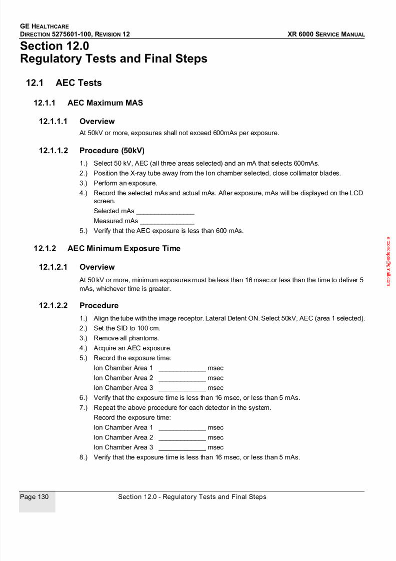
7/24/2019 GE XR6000 X-Ray - Service Manual
http://slidepdf.com/reader/full/ge-xr6000-x-ray-service-manual 130/421
GE HEALTHCARE
DIRECTION 5275601-100, REVISION 12 XR 6000 SERVICE MANUAL
Page 130 Section 12.0 - Regulatory Tests and Final Steps
Section 12.0 Regulatory Tests and Final Steps
12.1 AEC Tests
12.1.1 AEC Maximum MAS
12.1.1.1 Overview At 50kV or more, exposures shall not exceed 600mAs per exposure.
12.1.1.2 Procedure (50kV)
1.) Select 50 kV, AEC (all three areas selected) and an mA that selects 600mAs.
2.) Position the X-ray tube away from the Ion chamber selected, close collimator blades.
3.) Perform an exposure.
4.) Record the selected mAs and actual mAs. After exposure, mAs will be displayed on the LCDscreen.
Selected mAs ________________
Measured mAs _______________
5.) Verify that the AEC exposure is less than 600 mAs.
12.1.2 AEC Minimum Exposure Time
12.1.2.1 Overview
At 50 kV or more, minimum exposures must be less than 16 msec.or less than the time to deliver 5
mAs, whichever time is greater.
12.1.2.2 Procedure
1.) Align the tube with the image receptor. Lateral Detent ON. Select 50kV, AEC (area 1 selected).
2.) Set the SID to 100 cm.
3.) Remove all phantoms.
4.) Acquire an AEC exposure.
5.) Record the exposure time:
Ion Chamber Area 1 _____________ msec
Ion Chamber Area 2 _____________ msec
Ion Chamber Area 3 _____________ msec
6.) Verify that the exposure time is less than 16 msec, or less than 5 mAs.
7.) Repeat the above procedure for each detector in the system.
Record the exposure time:
Ion Chamber Area 1 _____________ msec
Ion Chamber Area 2 _____________ msec
Ion Chamber Area 3 _____________ msec
8.) Verify that the exposure time is less than 16 msec, or less than 5 mAs.
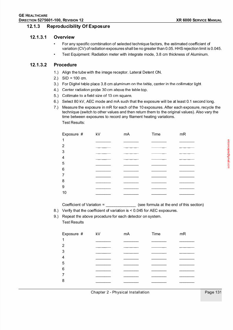
7/24/2019 GE XR6000 X-Ray - Service Manual
http://slidepdf.com/reader/full/ge-xr6000-x-ray-service-manual 131/421
GE HEALTHCARE
DIRECTION 5275601-100, REVISION 12 XR 6000 SERVICE MANUAL
Chapter 2 - Physical Installation Page 131
12.1.3 Reproducibility Of Exposure
12.1.3.1 Overview• For any specific combination of selected technique factors, the estimated coefficient of
variation (CV) of radiation exposures shall be no greater than 0.05. HHS rejection limit is 0.045.
• Test Equipment: Radiation meter with integrate mode, 3.8 cm thickness of Aluminum.
12.1.3.2 Procedure
1.) Align the tube with the image receptor. Lateral Detent ON.
2.) SID = 100 cm.
3.) For Digital table place 3.8 cm aluminum on the table, center in the collimator light.
4.) Center radiation probe 30 cm above the table top.
5.) Collimate to a field size of 13 cm square.
6.) Select 80 kV, AEC mode and mA such that the exposure will be at least 0.1 second long.
7.) Measure the exposure in mR for each of the 10 exposures. After each exposure, recycle the
technique (switch to other values and then return them to the original values). Also vary the
time between exposures to record any filament heating variations.
Test Results:
Exposure # kV mA Time mR
1 _______ _______ _______ _______
2 _______ _______ _______ _______
3 _______ _______ _______ _______
4 _______ _______ _______ _______
5 _______ _______ _______ _______
6 _______ _______ _______ _______
7 _______ _______ _______ _______
8 _______ _______ _______ _______
9 _______ _______ _______ _______
10 _______ _______ _______ _______
Coefficient of Variation = ______________ (see formula at the end of this section)
8.) Verify that the coefficient of variation is < 0.045 for AEC exposures.
9.) Repeat the above procedure for each detector on system.
Test Results
Exposure # kV mA Time mR
1 _______ _______ _______ _______
2 _______ _______ _______ _______
3 _______ _______ _______ _______
4 _______ _______ _______ _______
5 _______ _______ _______ _______
6 _______ _______ _______ _______
7 _______ _______ _______ _______
8 _______ _______ _______ _______

7/24/2019 GE XR6000 X-Ray - Service Manual
http://slidepdf.com/reader/full/ge-xr6000-x-ray-service-manual 132/421
GE HEALTHCARE
DIRECTION 5275601-100, REVISION 12 XR 6000 SERVICE MANUAL
Page 132 Section 12.0 - Regulatory Tests and Final Steps
9 _______ _______ _______ _______
10 _______ _______ _______ _______
Coefficient of Variation = ______________ (see formula at the end of this section)
10.) Verify that the coefficient of variation is < 0.045 for AEC exposures.
Calculation for Coefficient of Variation (C.V.):
Formula: C.V. = s / X(avg.) where s = sample standard deviation (n-1)
Sample standard deviation (s) can be calculated on a calculator with statistics functions (such
as the TI36Y) as follows:
* Clear the stat register, press (CSR).
* Enter the first reading and then press (+). Repeat this step for all readings.
* Press (mean) to get X(avg.).
* Press sample standard deviation key (n-1).
* Enter the results in the formula above.
12.2 Final Installation and Admin Tasks
1.) Ready system for normal customer operation.
2.) Install all covers on system equipment. (Refer to above for procedure.)
3.) Remove trash, remove installation equipment and tools, clean up room and store service
manuals.
4.) Fill out Product Locator Cards and return them.
Part No. Part Name
5183178 Pioneer console assembly
5180891 Standard integrated table assembly
5183392 Standard integrated tube stand assembly
5189248 Manual collimator
5192454 50kW Tube: Toshiba E7843X
2212259-2 Generator (VR Jedi 50 R1T)
5220653 Platform PDU
5213401 78l 10:1 180cm grid
080-1004 60l 10:1 180cm grid
5198785 40l 10:1 180cm grid
5167409-1 Table ion chamber
5167409-2 Wall stand ion chamber

7/24/2019 GE XR6000 X-Ray - Service Manual
http://slidepdf.com/reader/full/ge-xr6000-x-ray-service-manual 133/421
GE HEALTHCARE
DIRECTION 5275601-100, REVISION 12 XR 6000 SERVICE MANUAL
Chapter 2 - Physical Installation Page 133
5.) Record installation time in Service database.
5176556 Pioneer system console control board
Part No. Part Name

7/24/2019 GE XR6000 X-Ray - Service Manual
http://slidepdf.com/reader/full/ge-xr6000-x-ray-service-manual 134/421
GE HEALTHCARE
DIRECTION 5275601-100, REVISION 12 XR 6000 SERVICE MANUAL
Page 134 Section 12.0 - Regulatory Tests and Final Steps
This page is intentionally left blank.

7/24/2019 GE XR6000 X-Ray - Service Manual
http://slidepdf.com/reader/full/ge-xr6000-x-ray-service-manual 135/421
GE HEALTHCARE
DIRECTION 5275601-100, REVISION 12 XR 6000 SERVICE MANUAL
Chapter 3 - Configuraton & Calibration Page 135
Chapter 3 - Configuraton & Calibration
Section 1.0
Configuration & Calibration List
Section 2.0 Configuration & Calibration Contents
2.1 System Configuration
During the Application screen, press these two buttons for more than 5sec to switch from
Application screen to Configuration screen. If system is at configuration screen, press these two
buttons to switch from Configuration screen to Application screen. At the configuration screen,
operator can configure the Type of Generator, System Power, Table AEC, Wall Stand, Wall Stand
AEC.
1.) Configure the Generator
Press the Patient View button to configure that the generator is Jedi or Djinn.
2.) Configure the System Power
Press Receptor button to configure the system power is 50kW.
3.) Configure Table AEC
Section Content Page
2.1 System Configuration 123
2.2 X-ray Tube Seasoning 124
2.3 Service Software User Guide 139
2.4 Tube Configuration 145
2.5 Receptor Programming 146
2.6 Automated AEC Calibration 151
2.7 CR AEC Calibration 158
2.8 Checksum Validation 160
2.9 Backup and Restore Database Parameters 162
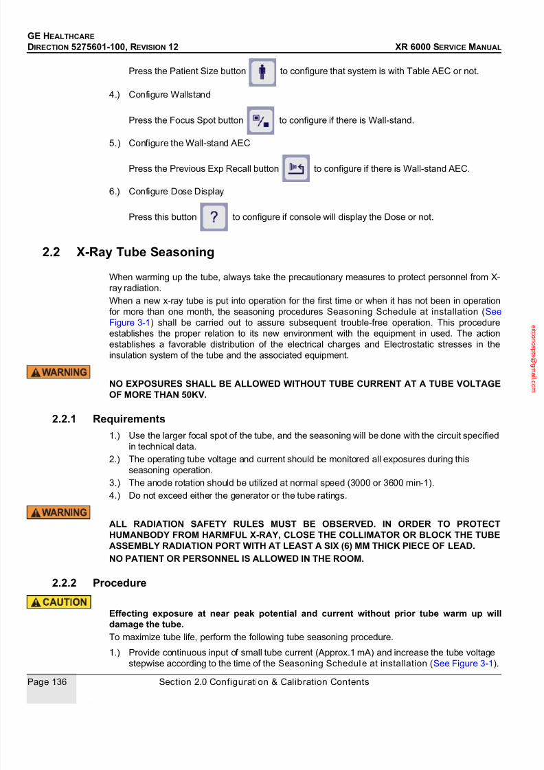
7/24/2019 GE XR6000 X-Ray - Service Manual
http://slidepdf.com/reader/full/ge-xr6000-x-ray-service-manual 136/421
GE HEALTHCARE
DIRECTION 5275601-100, REVISION 12 XR 6000 SERVICE MANUAL
Page 136 Section 2.0 Configuration & Calibration Contents
Press the Patient Size button to configure that system is with Table AEC or not.
4.) Configure Wallstand
Press the Focus Spot button to configure if there is Wall-stand.
5.) Configure the Wall-stand AEC
Press the Previous Exp Recall button to configure if there is Wall-stand AEC.
6.) Configure Dose Display
Press this button to configure if console will display the Dose or not.
2.2 X-Ray Tube Seasoning
When warming up the tube, always take the precautionary measures to protect personnel from X-
ray radiation.
When a new x-ray tube is put into operation for the first time or when it has not been in operation
for more than one month, the seasoning procedures Seasoning Schedule at installation (See
Figure 3-1) shall be carried out to assure subsequent trouble-free operation. This procedure
establishes the proper relation to its new environment with the equipment in used. The action
establishes a favorable distribution of the electrical charges and Electrostatic stresses in the
insulation system of the tube and the associated equipment.
NO EXPOSURES SHALL BE ALLOWED WITHOUT TUBE CURRENT AT A TUBE VOLTAGEOF MORE THAN 50KV.
2.2.1 Requirements
1.) Use the larger focal spot of the tube, and the seasoning will be done with the circuit specified
in technical data.
2.) The operating tube voltage and current should be monitored all exposures during this
seasoning operation.
3.) The anode rotation should be utilized at normal speed (3000 or 3600 min-1).
4.) Do not exceed either the generator or the tube ratings.
ALL RADIATION SAFETY RULES MUST BE OBSERVED. IN ORDER TO PROTECT
HUMANBODY FROM HARMFUL X-RAY, CLOSE THE COLLIMATOR OR BLOCK THE TUBEASSEMBLY RADIATION PORT WITH AT LEAST A SIX (6) MM THICK PIECE OF LEAD.
NO PATIENT OR PERSONNEL IS ALLOWED IN THE ROOM.
2.2.2 Procedure
Effecting exposure at near peak potential and current without prior tube warm up willdamage the tube.
To maximize tube life, perform the following tube seasoning procedure.
1.) Provide continuous input of small tube current (Approx.1 mA) and increase the tube voltage
stepwise according to the time of the Seasoning Schedule at installation (See Figure 3-1).
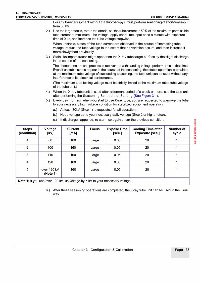
7/24/2019 GE XR6000 X-Ray - Service Manual
http://slidepdf.com/reader/full/ge-xr6000-x-ray-service-manual 137/421
GE HEALTHCARE
DIRECTION 5275601-100, REVISION 12 XR 6000 SERVICE MANUAL
Chapter 3 - Configuraton & Calibration Page 137
For any X-ray equipment without the fluoroscopy circuit, perform seasoning of short-time input
from 50 kV.
2.) Use the larger focus, rotate the anode, set the tube current to 50% of the maximum permissible
tube current at maximum tube voltage, apply short-time input once a minute with exposure
time of 0.1s, and increase the tube voltage stepwise.
When unstable, states of the tube current are observed in the course of increasing tube
voltage, reduce the tube voltage to the extent that no variation occurs, and then increase itmore slowly than previously.
3.) Stain like impact traces might appear on the X-ray tube target surface by the slight discharge
in the course of the seasoning.
The phenomena are one process to recover the withstanding voltage performance at that time,
Even if unstable states appear in the course of the seasoning, the stable operation is obtained
at the maximum tube voltage of succeeding seasoning, the tube unit can be used without any
interference to its electrical performance.
(The maximum tube testing voltage must be strictly limited to the maximum rated tube voltage
of the tube unit.)
4.) When the X-ray tube unit is used after a dormant period of a week or more, use the tube unit
after performing the Seasoning Schedule at Starting (See Figure 3-1).
5.) Every day morning, when you start to use X-ray tube, you are requested to warm-up the tube
to your necessary high voltage condition for stabilized equipment operation.
a.) At least 80kV (Step 1) is requested for all operation.
b.) Need voltage up to your necessary daily voltage (Step 2 or higher step).
c.) If discharge happened, re-warm up again under the previous condition.
6.) After these seasoning operations are completed, the X-ray tube unit can be used in the usual
way.
Steps(condition)
Voltage[kV]
Current[mA]
Focus Expose Time[sec.]
Cooling Time afterExposure [sec.]
Number ofcycle
1 80 160 Large 0.05 20 1
2 100 160 Large 0.05 20 1
3 110 160 Large 0.05 20 1
4 120 160 Large 0.05 20 1
5 over 120 kV
(Note 1)
160 Large 0.05 20 1
Note 1: If you use over 120 kV, up voltage by 5 kV to your necessary voltage.

7/24/2019 GE XR6000 X-Ray - Service Manual
http://slidepdf.com/reader/full/ge-xr6000-x-ray-service-manual 138/421
GE HEALTHCARE
DIRECTION 5275601-100, REVISION 12 XR 6000 SERVICE MANUAL
Page 138 Section 2.0 Configuration & Calibration Contents
Figure 3-1 Seasoning Schedule

7/24/2019 GE XR6000 X-Ray - Service Manual
http://slidepdf.com/reader/full/ge-xr6000-x-ray-service-manual 139/421
GE HEALTHCARE
DIRECTION 5275601-100, REVISION 12 XR 6000 SERVICE MANUAL
Chapter 3 - Configuraton & Calibration Page 139
Note: Please press and together to get into HUB Mode.
2.3 Service Software User Guide
2.3.1 SuppliesNone.
2.3.2 Tools• JEDI service software (the software is a DOS application)
• Console R232 cable (5194292)
• Computer with floppy or CD drive
2.3.3 Safety PrecautionsNot applicable.
2.3.4 PrerequisitesBasic knowledge of PC based computer laptop, DOS and usage of Microsoft WINDOWS.
2.3.5 Personnel1 person.
2.3.6 Time15 minutes.
2.3.7 Procedure
2.3.7.1 Loading service software on service laptopThe Service software is a DOS application. It can operate under DOS or Windows; but for softwaredownload or database backup, it is required to run ASIAN.exe under DOS to avoidcommunication problem (with the mouse, click on START, SHUTDOWN, RESTART
COMPUTER UNDER DOS MODE; see Chapter 9 - - Service Tool Job Cards - Section 1.0 -
Software Download / Upgrade).
To load the software on to the hard drive:
• Power ON Service laptop. Under Windows, run the File Manager (Explorer))
• Create a new directory (e.g.: JEDISVC) under C:\
• Insert the "Service Software" CD delivered with the equipment in the Service Tool set into theCD drive.
• Copy all the files from the CD to your hard drive.
(Double click on A:\, drag and drop on C:\ JEDISVC or whatever name of your directory.)
• Double click the file JEDP424B expanding the software to your hard drive.
The service software is installed and ready for use.
2.3.7.2 Using service softwareConnect Service terminal as follows:
• Use the 9 pin Service cable, Part No 2207478, to connect serial line of Service terminal to
system console.

7/24/2019 GE XR6000 X-Ray - Service Manual
http://slidepdf.com/reader/full/ge-xr6000-x-ray-service-manual 140/421
GE HEALTHCARE
DIRECTION 5275601-100, REVISION 12 XR 6000 SERVICE MANUAL
Page 140 Section 2.0 Configuration & Calibration Contents
• Switch on the Service terminal.
• To run the program:
Under Windows:
- Exit Windows. Restart computer in MS-DOS mode.
- Select Disk Drive from where you want to run the program: C: [enter]
- Change to the new directory
- Type: "ASIAN" [enter] to run the program
The following screen appears:
• Power ON the generator.
• Press function key F1.
The following screen appears:
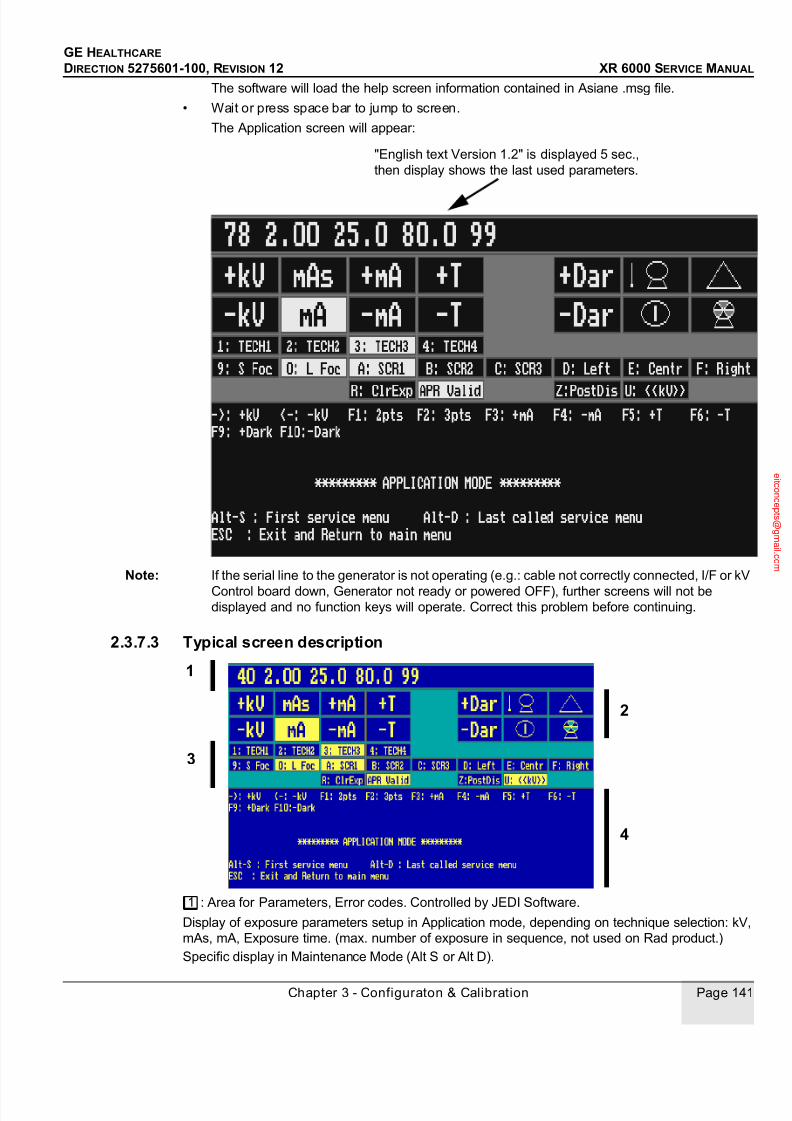
7/24/2019 GE XR6000 X-Ray - Service Manual
http://slidepdf.com/reader/full/ge-xr6000-x-ray-service-manual 141/421
GE HEALTHCARE
DIRECTION 5275601-100, REVISION 12 XR 6000 SERVICE MANUAL
Chapter 3 - Configuraton & Calibration Page 141
The software will load the help screen information contained in Asiane .msg file.
• Wait or press space bar to jump to screen.
The Application screen will appear:
Note: If the serial line to the generator is not operating (e.g.: cable not correctly connected, I/F or kV
Control board down, Generator not ready or powered OFF), further screens will not bedisplayed and no function keys will operate. Correct this problem before continuing.
2.3.7.3 Typical screen description
: Area for Parameters, Error codes. Controlled by JEDI Software.
Display of exposure parameters setup in Application mode, depending on technique selection: kV,
mAs, mA, Exposure time. (max. number of exposure in sequence, not used on Rad product.)
Specific display in Maintenance Mode (Alt S or Alt D).
"English text Version 1.2" is displayed 5 sec.,
then display shows the last used parameters.
1
3
2
4
1
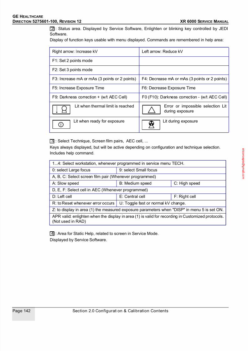
7/24/2019 GE XR6000 X-Ray - Service Manual
http://slidepdf.com/reader/full/ge-xr6000-x-ray-service-manual 142/421
GE HEALTHCARE
DIRECTION 5275601-100, REVISION 12 XR 6000 SERVICE MANUAL
Page 142 Section 2.0 Configuration & Calibration Contents
: Status area. Displayed by Service Software, Enlighten or blinking key controlled by JEDI
Software.
Display of function keys usable with menu displayed. Commands are remembered in help area:
: Select Technique, Screen film pairs, AEC cell, ...
Keys always displayed, but will be active depending on configuration and technique selection.
Includes help command.
: Area for Static Help, related to screen in Service Mode.
Displayed by Service Software.
Right arrow: Increase kV Left arrow: Reduce kV
F1: Set 2 points mode
F2: Set 3 points mode
F3: Increase mA or mAs (3 points or 2 points) F4: Decrease mA or mAs (3 points or 2 points)
F5: Increase Exposure Time F6: Decrease Exposure Time
F9: Darkness correction + (w/t AEC Cell) F0 (F10): Darkness correction - (w/t AEC Cell)
Lit when thermal limit is reached Error or impossible selection Lit
during exposure
Lit when ready for exposure Lit during exposure
1...4: Select workstation, whenever programmed in service menu TECH.
0: select Large focus 9: select Small focus
A, B, C: Select screen film pair (Whenever programmed)
A: Slow speed B: Medium speed C: High speedD, E, F: Select cell in AEC (Whenever programmed)
D: Left cell E: Central cell F: Right cell
R: to Reset whenever error occurs U: Toggle fast or normal kV change.
Z: to display in area (1) the measured exposure parameters when "DISP" in menu 5 is set ON.
APR valid: enlighten when the display in area (1) is valid for recording in Customized protocols.
(Not used in RAD)
2
3
4

7/24/2019 GE XR6000 X-Ray - Service Manual
http://slidepdf.com/reader/full/ge-xr6000-x-ray-service-manual 143/421
GE HEALTHCARE
DIRECTION 5275601-100, REVISION 12 XR 6000 SERVICE MANUAL
Chapter 3 - Configuraton & Calibration Page 143
SELECTING MAINTENANCE AND APPLICATION MODE; MAJOR KEYS
SERVICE MENU TREE BREAKDOWN
• Type [ALT] & [S] (Together) to go to Maintenance Menus (MENU 3)
• Type [ ] and [ ] keys to select a menu.
• Figure 3-2 shows the relationship between the Maintenance Mode menus and the function
keys used to access those menus.
• To return to a higher level, key in [R]
The darkened menus are used for Generator and room setup (Configuration and Calibration):menu 3, 4, 5.
Menu 3 is used to Configure the system
Menu 4 is used to calibrate AEC mode (Automatic Exposure Control)
Menu 5 is used to perform Checksum
Menu 1 is used to perform generator test and diagnostics.
Menu 2 is used to enter Date and Time, view/clear error log, and view/clear tube and generator
recorded tracking Data.
FROM PROCEDURE TO
APPLICATION MODE Type <ALT> - <S > (Together) SETUP/MAINTENANCE
MODEMENU 3
APPLICATION MODE Type <ALT> - <D > (Together) SETUP/MAINTENANCE
MODELAST MENU OR
SUB-MENU selected.
SETUP/MAINTENANCE
MODE
From any menu, type <R > (several
times if necessary) or <Q >
APPLICATION MODE
[Q] Return to application mode
[R] Return to a higher level menu
[W] Validate
[ALT] & [S] (Together) Calibration mode (Menu 3)
[ALT] & [D] Calibration mode (Last menu called)
[ ] and [ ] In maintenance mode, to move through menus
[F1] to [F0] Function keys with action based on context.
Other keys Based on context. Main function recalled in the screen and also
in sections wherever used.
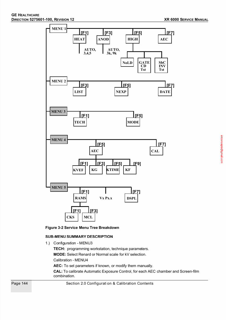
7/24/2019 GE XR6000 X-Ray - Service Manual
http://slidepdf.com/reader/full/ge-xr6000-x-ray-service-manual 144/421
GE HEALTHCARE
DIRECTION 5275601-100, REVISION 12 XR 6000 SERVICE MANUAL
Page 144 Section 2.0 Configuration & Calibration Contents
Figure 3-2 Service Menu Tree Breakdown
SUB-MENU SUMMARY DESCRIPTION
1.) Configuration - MENU3
TECH: programming workstation, technique parameters.
MODE: Select Renard or Normal scale for kV selection.
Calibration - MENU4
AEC: To set parameters if known, or modify them manually.
CAL: To calibrate Automatic Exposure Control, for each AEC chamber and Screen-film
combination.
MENU 3 [F1]
TECH
MENU 4
[F5]
AEC
KG KVEF
[F3][F1]
KTIME
[F5]
KF
MENU 5
[F1]
RAMS
MCLCKS
[F3][F1]
Vx Px.x
MODE
[F5]
[F9]
DSPL
[F7]
CAL
[F7]
MENU 2
LIST
[F3]
NEXP
[F5]
DATE
[F7]
MENU 1
HEAT
[F1]
HIGH
[F5]
AEC
[F7]
AUTO,3,4,5
ANOD
[F3]
AUTO,3k, 9k
GATENoLDCDTst
ShC INV Tst

7/24/2019 GE XR6000 X-Ray - Service Manual
http://slidepdf.com/reader/full/ge-xr6000-x-ray-service-manual 145/421
GE HEALTHCARE
DIRECTION 5275601-100, REVISION 12 XR 6000 SERVICE MANUAL
Chapter 3 - Configuraton & Calibration Page 145
(See 2.6 - Automatic AEC Calibration)
2.) Ram - MENU5
RAMS: NVRAm operation & display:
- CKSM: To update Checksum after configuration, calibration, parameter change. (See 2.8
- Checksum Validation)
- MCLR: Clear NVRam memory. Normally not to be used, unless specifically instructed.
Note: Do not use if Data Base backup has not been performed previously. Vx Px.x: Display generator software version (e.g. P3.3)
DSPL: In Maintenance Mode, to display parameter after exposure using key [Z]
3.) Utilities - MENU2
LIST: To display last recorded error codes (up to 64)
- Last error is viewed with Date and Time
- Function keys allow to scroll down and up
- [Z] to get back to the last recorded error
- Same consecutive error are counted Up in the same line
- [^H ], and [W] to clear error log
NEXP: To view/clear tube and generator recorded tracking Data. Clear must be performedonly when replacing X-Ray tube. Meaning of each parameter is found in Chapter 9 - - Service
Tool Job Cards - Section 2.0 - Tube Replacement Software Procedure.
DATE: To enter / modify the date and time.
4.) Diagnostics - MENU1
HEAT: To exercise Heater/filament function.
- Auto: run fixed current on both filament (if 2 filaments) in sequence on selected tube (If
more than 1).
- L or S: run 3, 4, or 5 Amps on Large or Small Focus.
ANOD: To exercise Rotor function.
- Auto: run rotation cycle in Low Speed then High Speed (If allowed by configuration) on
selected tube. (If more than 1)- 3k: run one cycle acceleration, hold, break in Low Speed on selected tube (If more than 1)
- 9k: run one cycle acceleration, hold, break in High Speed (If allowed by configuration) on
selected tube (If more than 1)
HIGH: To exercise High Voltage function.
- NoLD: To troubleshoot HV problem, without mA nor rotation with or without X-Ray tube.
Test is run from 80 to max. kV, adjustable from 1 to 60 sec.
- Gate CD Test: to verify operation of the gate command board on the Inverter. Test is run
during 10 sec. At 0 kV.
Note: Requires manual set up. Read related information in diagnostics section.
- ShC INV Tst: To verify operation of inverter with inverter in short circuit. Test is run during
100 msec. At 0 kV.Note: Requires manual set up. Read related information in diagnostics section.
AEC: To verify operation of AEC board. Refer to diagnostics section.
2.4 Tube Configuration
2.4.1 SuppliesNone.

7/24/2019 GE XR6000 X-Ray - Service Manual
http://slidepdf.com/reader/full/ge-xr6000-x-ray-service-manual 146/421
GE HEALTHCARE
DIRECTION 5275601-100, REVISION 12 XR 6000 SERVICE MANUAL
Page 146 Section 2.0 Configuration & Calibration Contents
2.4.2 Tools• JEDI service software (the software is a DOS application)
• Console R232 cable (5194292)
• Computer with floppy or CD drive
2.4.3 Safety PrecautionsNot applicable.
2.4.4 PrerequisitesThe service terminal must be configured and software installed (refer to 2.3 - Service Software User
Guide).
2.4.5 Personnel1 person.
2.4.6 Time
15 minutes.
2.4.7 Procedure
2.4.7.1 Load software according to tube present in the installation A database is available on the JEDI Service Software supplied in Service Tools:
• for 50 kW tube: Type E7843X File = E7843_R?.mx (? means the current revision)
Load the file corresponding to the tube present in the installation from Service Terminal. Refer to
2.9 - Backup and Restore Database Parameters.
2.4.7.2 Verify According to the tube used in the installation, verify if 50 kW database loaded for tube E7843X
• The maximum mA displayed on the console must be 630 mA for 80 kV.
The word "Workstation" is incorrectly used and displayed in the JEDI software screens.
"Workstation" actually refers to the word "Receptor".
2.5 Receptor Programming
2.5.1 Supplies
None.
2.5.2 Tools• JEDI service software (the software is a DOS application)
• Console R232 cable (5194292)
• Computer with floppy or CD drive
2.5.3 Safety PrecautionsThe JEDI is factory preprogrammed. Therefore, even if the data appears to correspond to the pre-
programming, it must be confirmed. For example, AEC enable, wall bucky enable must be
confirmed.
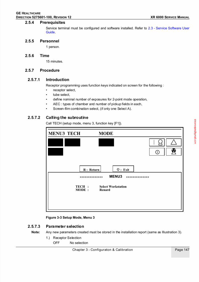
7/24/2019 GE XR6000 X-Ray - Service Manual
http://slidepdf.com/reader/full/ge-xr6000-x-ray-service-manual 147/421
GE HEALTHCARE
DIRECTION 5275601-100, REVISION 12 XR 6000 SERVICE MANUAL
Chapter 3 - Configuraton & Calibration Page 147
2.5.4 PrerequisitesService terminal must be configured and software installed. Refer to 2.3 - Service Software User
Guide.
2.5.5 Personnel1 person.
2.5.6 Time15 minutes.
2.5.7 Procedure
2.5.7.1 IntroductionReceptor programming uses function keys indicated on screen for the following :
• receptor select,
• tube select,
• define nominal number of exposures for 2-point mode operation,• AEC : types of chamber and number of pickup fields in each,
• Screen-film combination select, (if only one Select A).
2.5.7.2 Calling the subroutineCall TECH (setup mode, menu 3, function key [F1]).
Figure 3-3 Setup Mode, Menu 3
2.5.7.3 Parameter selectionNote: Any new parameters created must be stored in the installation report (same as Illustration 3).
1.) Receptor Selection
OFF No selection
: ExitR : Return
-> F1
MENU3
<-
TECH : Select WorkstationMODE : Renard
MENU3 **************
TECH
**************
MODE
F5

7/24/2019 GE XR6000 X-Ray - Service Manual
http://slidepdf.com/reader/full/ge-xr6000-x-ray-service-manual 148/421
GE HEALTHCARE
DIRECTION 5275601-100, REVISION 12 XR 6000 SERVICE MANUAL
Page 148 Section 2.0 Configuration & Calibration Contents
SPE * Anatomic (for RF room)
DIR* Anatomic (for RAD room)
POMU Wall-mounted Bucky (i.e. SG50 or SG70)
SETE Spot-film device technique on remote-controlled table (i.e. Prestilix 1600)
TOPO Tomography Bucky
TOSE Tomography spot-film device technique
POTA Table-mounted Bucky
PULM Pulmorapid
CHAN Film changer
TOCO Special tomographic applications
SECO Spot-film device technique on conventional table
NUME Digital mode
TONU Digital tomography
Use the [ ] and [ ] keys to select.
* For RAD
TECH 1 = DIRTECH 2 = POTA (TABLE BUCKY with moving grid) or DIR (if fixed grid).
TECH 3 = POMU (with moving grid) or DIR (if fixed grid) or OFF (if no Wall Bucky).
Figure 3-4 Receptor Menu
2.) Tube Selection
T1 Tube 1 only
3.) Select the number of nominal exposures for 2-point mode operation.
Receptor Tube Tomo tech & time
Nominal numberof exposures In2-point mode
Type of AEC

7/24/2019 GE XR6000 X-Ray - Service Manual
http://slidepdf.com/reader/full/ge-xr6000-x-ray-service-manual 149/421
GE HEALTHCARE
DIRECTION 5275601-100, REVISION 12 XR 6000 SERVICE MANUAL
Chapter 3 - Configuraton & Calibration Page 149
Suggested values are given below:
DIR N = 2 POTA N = 2
POMU N = 2
Use function keys [F5] and [F6] to select.
4.) Selection of Exposure Chamber
IN1 Ionization chamber 1 (for Table Bucky Receptor POTA).
IN2 Ionization chamber 2 (for Wall Bucky Receptor on - POMU).
Select AEC in or out using function keys [F7] et [F8]. Each chamber corresponds to a specific
technique, i.e. POMU and POTA.
5.) Control Console Function Key assignment
Function keys are assigned using the alphanumeric keyboard ([1] corresponds to function key
1, etc., up to 8). Use the shift key for numbers 0 to 9.
With the RAD Console only four techniques are available.
The technique selected is shown in reverse video in zone 3.
6.) Selection of screen-film combination used
Keys [A], [B] and [C] are used to select the first, second and third screen-film combinations,
respectively.The combination selected is displayed in reverse video in zone 2.
Press the key again to cancel a selection.
One combination is always selected. Select Key A for the RAD used screen film combination.
7.) Selection of Number of Pickup Fields
The number of pickup fields of the exposure chamber selected for AEC Mode with ionizing
chamber or II must be keyed in:
[D] middle pick-up field (one),
[F] three pick-up fields.
The number of pick-up fields is displayed in reverse video in zone 3.
8.) ValidationUse [W] to validate all values for a given function appearing on the screen.
2.5.7.4 Renard or normal scale for kv selection
1.) Go to Service Mode, and call Menu 3 using the arrows on the keyboard.
2.) Call MODE by pressing F5.
3.) Select NORMAL or RENARD Scale by pressing F5.
4.) Hit W to confirm.
2.5.7.5 Date & Time
To enter the Date and Time:1.) Go to Service Mode, and call Menu 2 using the arrows on the keyboard.
2.) Call DATE by pressing F7.
3.) Enter date (MM DD YYYY) via numeric keypad.
4.) Hit W to confirm.
5.) Hit F1.
6.) Enter time (HH MM) via numeric keypad.
7.) Hit W to confirm.
When replacing the battery in the CPU Board, clear the year-counter display on the righthand side
via F7 and F9 to confirm.

7/24/2019 GE XR6000 X-Ray - Service Manual
http://slidepdf.com/reader/full/ge-xr6000-x-ray-service-manual 150/421
GE HEALTHCARE
DIRECTION 5275601-100, REVISION 12 XR 6000 SERVICE MANUAL
Page 150 Section 2.0 Configuration & Calibration Contents
Anytime programming is modified, checksum must be validated (refer to 2.8 - Checksum
Validation).
Table 3-1 Receptor Parameters (Example for RAD with Wall Bucky and two ionisationchambers)
RECEPTOR SELECT
FUNCTION 1 2 3 4 5 6 7 8
RECEPTOR DIR POTA POMU OFF OFF OFF OFF OFFTUBE T1 T1 T1
NUMBER
OFEXPOSURES
IN 2-POINT
MODE
2 2 2
TOMOGRAPHIC
UNIT USED:
Y1
T1
Y2
T2Y3
T3
Y4
T4
Y5
T5
N N N
TYPE OF
CHAMBER
OUT IN1 IN2
mA
PLATEAUTIME
FOR1-POINTMODE
EXTERNAL
RECEPTORCO
MMAND*
No No No
SCREEN-FILM
COMBINATION
S
1
2
3
A A
NUMBEROFPICK-
UPFIELDS
- 3 3 Number of cells usedin AEC
MODE RENARD OR NORMAL kV SELECTION

7/24/2019 GE XR6000 X-Ray - Service Manual
http://slidepdf.com/reader/full/ge-xr6000-x-ray-service-manual 151/421
GE HEALTHCARE
DIRECTION 5275601-100, REVISION 12 XR 6000 SERVICE MANUAL
Chapter 3 - Configuraton & Calibration Page 151
2.6 Automatic AEC Calibration
2.6.1 SuppliesNone.
2.6.2 Tools• Sensitometer
• Densitometer
• Set of five plexiglass plates (5 cm x 25 cm x 25 cm)
For 5 cm, it is 2 inches
OR
• A plastic bucket with a minimum height of 25 cm (for water)
• JEDI service software (the software is a DOS application)
• Console R232 cable (5194292)
• Computer with floppy or CD drive
2.6.3 Safety precautionsStandard precautions for work with ionizing radiation.
2.6.4 Personnel1 person.
2.6.5 Time1 hour.
2.6.6 Prerequisites• Working knowledge of service terminal and installed software,
• Service terminal must be configured and software installed,
• Workstation configuration done,
• AEC option must be installed.
2.6.7 PROCEDURE
2.6.7.1 Development equipment
CHECK DEVELOPMENT EQUIPMENT
• Check that the automatic processor is available
• Check that solution concentrations and temperatures comply with the manufacturer's
specifications.
• Plot a sensitometrics curve to determine the gamma value of the film and to assess solution
quality.
• All the gray scale levels should be visible, and the base fog should not exceed 0.2 for the
development equipment to be correct.
Note: This procedure normally requires a sensitometer. If this is not available, proceed as follows:
• Run 2 exposures, using the same screen-film combination but with different mAs settings,
mAs(f1) and mAs(f2).
• Develop and measure the density d of each, d(f1) and d(f2). (Measured optical densities must
be between 1.0 and 2.0)

7/24/2019 GE XR6000 X-Ray - Service Manual
http://slidepdf.com/reader/full/ge-xr6000-x-ray-service-manual 152/421
GE HEALTHCARE
DIRECTION 5275601-100, REVISION 12 XR 6000 SERVICE MANUAL
Page 152 Section 2.0 Configuration & Calibration Contents
• Use the formula below to determine gamma:
Gamma = ( d(f2) - d(f1) ) / log10 (mAs(f2)/mAs (f1))
• If gamma is not between 2 and 3 change or renew the solution
2.6.7.2 Preliminary Remarks
1.) All calibrations must be performed with a source to image receptor distance between 0.8m
and 1.2m.
2.) Center the phantom over the middle pickup tube field.
3.) A calibration procedure has to be performed for each combination of ionization chamber and
screen-film.
4.) If the same screen-film combinations are used for several ionization chambers (e.g.
positionner and bucky), adjust the positionner chamber first, and adust KG only for the other
chambers.
For known screen-film combination or ionization chamber, KVEF, KT and KG could be entered with
MENU4 AEC (F5 key). Refer to 2.3 - Service Software User Guide.
2.6.7.3 PrincipleThe automation of this calibration is to use the optical density entered after one exposure or four
exposures to predict and propose the parameter for the next exposures. This leads to a reduction
in the number of exposures to run to find mAs, kV and reference AEC for a given optical density.
INIT
KVEF acquisition screen
Select ionization chamber
Select screen-film combination
Run kvef calibration
If needed run
Ktime calibration
If needed run
Format calibration
other screen-film ?
(2more possible)
Yes
No
Other ionization chamber ?(3 more possible)
Yes
Run kvef calibration
If needed run
Ktime calibration
other screen-film ?
No
Select screen-film combination
Run grid calibration
Other ionization chamber ?
Select ionization chamber
Yes
END
No
No
Yes
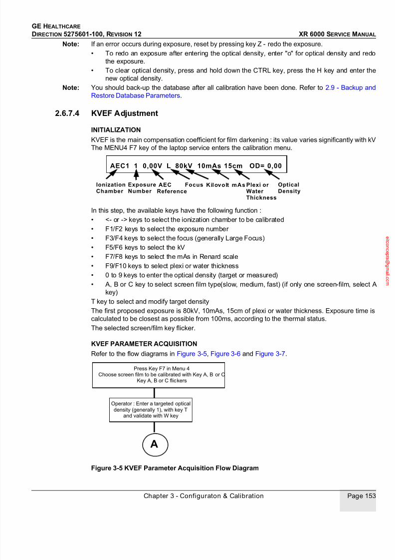
7/24/2019 GE XR6000 X-Ray - Service Manual
http://slidepdf.com/reader/full/ge-xr6000-x-ray-service-manual 153/421
GE HEALTHCARE
DIRECTION 5275601-100, REVISION 12 XR 6000 SERVICE MANUAL
Chapter 3 - Configuraton & Calibration Page 153
Note: If an error occurs during exposure, reset by pressing key Z - redo the exposure.
• To redo an exposure after entering the optical density, enter "o" for optical density and redo
the exposure.
• To clear optical density, press and hold down the CTRL key, press the H key and enter the
new optical density.
Note: You should back-up the database after all calibration have been done. Refer to 2.9 - Backup and
Restore Database Parameters.
2.6.7.4 KVEF Adjustment
INITIALIZATION
KVEF is the main compensation coefficient for film darkening : its value varies significantly with kV
The MENU4 F7 key of the laptop service enters the calibration menu.
In this step, the available keys have the following function :
• <- or -> keys to select the ionization chamber to be calibrated
• F1/F2 keys to select the exposure number
• F3/F4 keys to select the focus (generally Large Focus)
• F5/F6 keys to select the kV
• F7/F8 keys to select the mAs in Renard scale
• F9/F10 keys to select plexi or water thickness
• 0 to 9 keys to enter the optical density (target or measured)
• A, B or C key to select screen film type(slow, medium, fast) (if only one screen-film, select A
key)T key to select and modify target density
The first proposed exposure is 80kV, 10mAs, 15cm of plexi or water thickness. Exposure time is
calculated to be closest as possible from 100ms, according to the thermal status.
The selected screen/film key flicker.
KVEF PARAMETER ACQUISITION
Refer to the flow diagrams in Figure 3-5, Figure 3-6 and Figure 3-7.
Figure 3-5 KVEF Parameter Acquisition Flow Diagram
AEC1 1 0,00V L 80kV 10mAs 15cm OD= 0,00
IonizationChamber
ExposureNumber
AECReference
Kilovolt mAs Plexi orWater
Thickness
OpticalDensity
Focus
Operator : Enter a targeted opticaldensity (generally 1), with key T
and validate with W key
Press Key F7 in Menu 4Choose screen film to be calibrated with Key A, B or C
Key A, B or C flickers
A
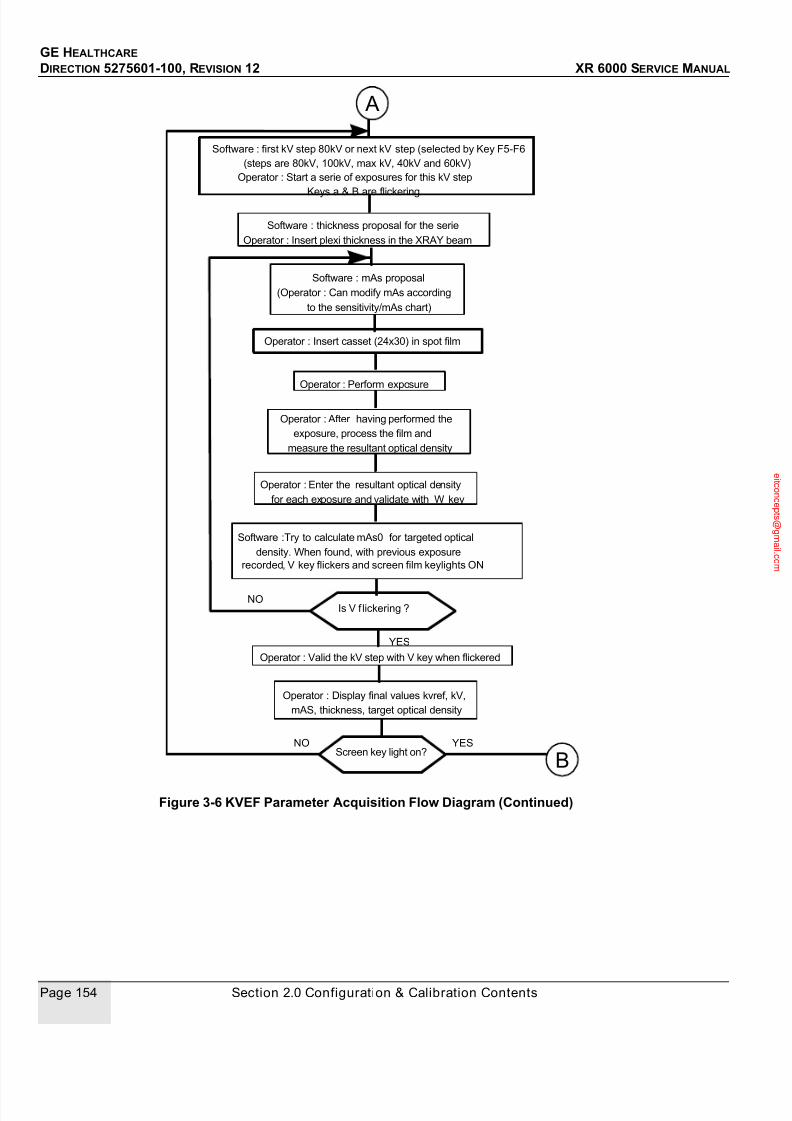
7/24/2019 GE XR6000 X-Ray - Service Manual
http://slidepdf.com/reader/full/ge-xr6000-x-ray-service-manual 154/421
GE HEALTHCARE
DIRECTION 5275601-100, REVISION 12 XR 6000 SERVICE MANUAL
Page 154 Section 2.0 Configuration & Calibration Contents
Figure 3-6 KVEF Parameter Acquisition Flow Diagram (Continued)
Software : first kV step 80kV or next kV step (selected by Key F5-F6
(steps are 80kV, 100kV, max kV, 40kV and 60kV)
Operator : Start a serie of exposures for this kV step
Software : thickness proposal for the serie
Operator : Insert plexi thickness in the XRAY beam
Software : mAs proposal
(Operator : Can modify mAs according
to the sensitivity/mAs chart)
Operator : Insert casset (24x30) in spot film
Operator : After having performed the
exposure, process the film and
measure the resultant optical density
Operator : Enter the resultant optical density
for each exposure and validate with W key
Software :Try to calculate mAs0 for targeted optical
density. When found, with previous exposure
recorded, V key flickers and screen film keylights ON
Is V f lickering ?NO
Operator : Valid the kV step with V key when flickered
YES
Operator : Display final values kvref, kV,
mAS, thickness, target optical density
Operator : Perform exposure
NOScreen key light on?
YES
B
A
Keys a & B are flickering

7/24/2019 GE XR6000 X-Ray - Service Manual
http://slidepdf.com/reader/full/ge-xr6000-x-ray-service-manual 155/421
GE HEALTHCARE
DIRECTION 5275601-100, REVISION 12 XR 6000 SERVICE MANUAL
Chapter 3 - Configuraton & Calibration Page 155
Figure 3-7 KVEF Parameter Acquisition Flow Diagram (Continued)
1.) Press T key and input Destination Density, then validates it with W key. Pressing T key
deselect Destination Density. Run the first exposures proposed by the software, develop the
films and measure the optical density. For each exposure, the software records the AEC signal
from the ionization chamber. The operator then selects the exposure number with F1/F2 keys,
enters the associated read optical density with key pad, and validates it with W key.
Note: There is no Beep during the exposure! The laptop Icon will light during X-ray.
2.) When the optical densities have been entered, the software calculate the parameters for thenext exposure regarding the result of the previous ones (AEC signal from ionization chamber
and optical density).
3.) The operator should run the next exposure proposed by the software, develop the film and
measure the optical density. The operator then selects the exposure number with F1/F2 keys
and enters the associated read optical density with the keypad, and validates it with the W key.
The software records the AEC signal from the ionization chamber. At each optical density
entered, the software evaluates if those values permit it to find the mAs0, which provides the
target density for this screen-film combination and the kV. When the mAs0 is found, the
software calculates the KVEF associated, then the V key starts to flicker to ask the operator to
validate the calibration by pressing the V keystroke.
4.) Select another kV and repeat the previous operation for all kV steps
Note: Don't forget to change the phantom thickness when changing kV settings!When all kV values are calibrated, the software extend the result and calculates the equivalent mAs
(for an optical density equal to the target value) to the kV,mA plan.
At the end of the first screen-film KVEF calibration , the operator selects the KT time calibration with
the V key after the V key has been illuminated.
K TIME PARAMETER ACQUISITION (EXPOSURE TIME CORRECTION)
In this step, the available keys have the following function :
• F1/F2 keys to select the exposure number
• 0 to 9 keys to enter the optical density (target or measured)
The operator could by-pass this calibration in depressing V key again.
The software uses the KVEF calibration to find the thickness for the first KTIME exposures : if the
mAs for 80kV, 15cm of plexi or water thickness are lower than 32mAs, the software calculates the
necessary plexi or water thickness to obtain more than 32 mAs. The calculated plexi or water
thickness is displayed.
End of kvef calibration. If first screen-film
calibration , select, if needed, time
next screen-film calibration
See descriptions of time and grid
calibrations below
B
AEC1 1 0,00V L 80kV 10mAs 15cm OD= 0,00
IonizationChamber
ExposureNumber
AECReference
Kilovolt mAs Plexi or Water
ThicknessOpticalDensity
Focus
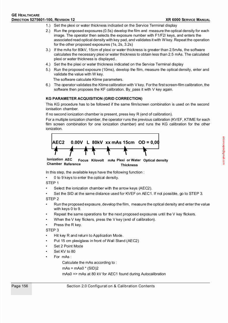
7/24/2019 GE XR6000 X-Ray - Service Manual
http://slidepdf.com/reader/full/ge-xr6000-x-ray-service-manual 156/421
GE HEALTHCARE
DIRECTION 5275601-100, REVISION 12 XR 6000 SERVICE MANUAL
Page 156 Section 2.0 Configuration & Calibration Contents
1.) Set the plexi or water thickness indicated on the Service Terminal display
2.) Run the proposed exposures (0.5s) develop the film and measure the optical density for each
image. The operator then selects the exposure number with F1/F2/ keys, and enters the
associated read optical density with key pad, and validates it with W key. Repeat the operation
for the other proposed exposures (1s, 2s, 3.2s)
3.) If the mAs for 80kV, 15cm of plexi or water thickness is greater than 2.5mAs, the software
calculates the necessary plexi or water thickness to obtain less than 2.5 mAs. The calculated
plexi or water thickness is displayed..
4.) Set the the plexi or water thickness indicated on the Service Terminal display
5.) Run the proposed exposure (10ms), develop the film, measure the optical density, enter and
validate the value with W key.
The software calculate Ktime parameters.
6.) The operator validates the Ktime calibration with V key. For the first screen-film calibration, the
software then proposes the KF calibration. By_pass it with V key again.
KG PARAMETER ACQUISITION (GRID CORRECTION)
This KG procedure has to be followed if the same film/screen combination is used on the second
ionisation chamber.
If no second ionization chamber is present, press key R (end of calibration).
For a multiple ionization chamber, the operator runs the previous calibration (KVEF, KTIME for each
film screen combination for one ionization chamber) and runs the KG calibration for the other
ionization.
In this step, the available keys have the following function :
• 0 to 9 keys to enter the optical density.
STEP 1
• Select the ionization chamber with the arrow keys (AEC2).
• Set the SID at the same distance used for KVEF on AEC1. If not possible, go to STEP 3.
STEP 2
• Run the proposed exposure, develop the film, measure the optical density and enter the value
with keys 0 to 9.
• Repeat the same operations for the next proposed exposures until the V key flickers.
• When the V key flickers, press the V key (end of calibration).
• Press the R key.STEP 3
• Hit key R and return to Application Mode.
• Put 15 cm plexiglass in front of Wall Stand (AEC2)
• Set 2 Point Mode
• Set KV to 80
• For mAs :
Calculate the mAs according to :
mAs = mAs0 * (SID)2
mAs0 => mAs at 80 kV for AEC1 found during Autocalibration
AEC2 0.00V L 80kV xx mAs 15cm OD = 0,00
Kilovolt mAs Optical density Focus IonizationChamber
Plexi or Water
Thickness
AEC
Reference
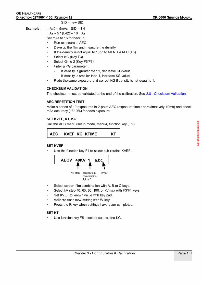
7/24/2019 GE XR6000 X-Ray - Service Manual
http://slidepdf.com/reader/full/ge-xr6000-x-ray-service-manual 157/421
GE HEALTHCARE
DIRECTION 5275601-100, REVISION 12 XR 6000 SERVICE MANUAL
Chapter 3 - Configuraton & Calibration Page 157
SID = new SID
Example: mAs0 = 5mAs SID = 1.4
mAs = 5 * (!.4)2 = 10 mAs
Set mAs to 16 for backup.
• Run exposure in AEC
• Develop the film and measure the density
• If the density is not equal to 1, go to MENU 4 AEC (F5)
• Select KG (Key F3)
• Select Grille 2 (Key F5/F6)
• Enter a KG parameter :
- If density is greater than 1, decrease KG value
- If density is smaller than 1, increase KG value
• Redo the same exposure and correct KG if density is not equal to 1.
CHECKSUM VALIDATION
The checksum must be validated at the end of the calibration. See 2.8 - Checksum Validation.
AEC REPETITION TESTMake a series of 10 exposures in 2-point AEC (exposure time : aproximatively 10ms) and check
mAs accuracy (+/-10%) for each exposure.
SET KVEF, KT, KG
Call the AEC menu (setup mode, menu4, function key [F5]).
SET KVEF
• Use the function key F1 to select sub-routine KVEF.
• Select screen-film combination with A, B or C keys.
• Select kV step 40, 60, 80, 100, or kVmax with F3/F4 keys.
• Set KVEF to known value with key pad.
• Validate each new setting with W key.• Press the R key when settings have been completed.
SET KT
• Use function key F5 to select sub-routine KG.
AEC KVEF KG KTIME KF
AECV 40KV 1 a.bc
screen-film
combination
1,2 or 3
KVEFKV step

7/24/2019 GE XR6000 X-Ray - Service Manual
http://slidepdf.com/reader/full/ge-xr6000-x-ray-service-manual 158/421
GE HEALTHCARE
DIRECTION 5275601-100, REVISION 12 XR 6000 SERVICE MANUAL
Page 158 Section 2.0 Configuration & Calibration Contents
• Use the following keys to select the screen-film combination : A for combination 1, B for
combination 2, C for combination3. The screen-film combination selected is displayed in
reverse video.
• Select time step number with F1/F2 keys. (N = 0 T = 10ms, N = 1 T = 100ms, N = 2 T = 500,
N = 3 T = 1s, N = 4 T = 2s, N = 5 T = 3.2s).
• If necessary, select time with F3/F4 keys.
• Set KTIME to the known value with F9/F10 keys.
• Validate each new setting with the W key.
• Press the R key when the settings have been completed.
SET KG• Use the function key F3 to select sub-routine KG.
• Use the function keys F5/F6 to scroll grid (grid number corresponds to the ionization chamber
number). Set KG to the known value using F9/F10 keys
• Validate each new setting with the W key
• Press the R key when settings have been completed.
CHECKSUM VALIDATION
The checksum must be validated after settings have been completed; refer to 2.8 - Checksum
Validation.
2.7 CR AEC Calibration
2.7.1 Systems with CR Filming OnlyUsually, a CR system does not require any compensation, so you can set all the values to 1.
2.7.1.1 Program Generator with Default CR Parameters
1.) Enter Generator service mode. Select MENU 4, AEC.
2.) Select the proper film - screen to calibrate.
Example:
3.) Program the generator with the following default values for KVEF, KG, KTIME, and KF.
AEC T N = 0 T = 0.5 1 a.bc
screen-film
combination
1,2 or 3
KTIMETimeTime step #
AEC G GRILLE 1 KG = a.b
grid no (f rom 1 to 4) KG 0.8 to 2
A: SCR1 B: SCR2 C: SCR3

7/24/2019 GE XR6000 X-Ray - Service Manual
http://slidepdf.com/reader/full/ge-xr6000-x-ray-service-manual 159/421
GE HEALTHCARE
DIRECTION 5275601-100, REVISION 12 XR 6000 SERVICE MANUAL
Chapter 3 - Configuraton & Calibration Page 159
Menu 4 F5 AEC F1 KVEF
Menu 4 F5 AEC F3 KG
(table) (chestand)
Menu 4 F5 AEC F5 KTIME
Menu 4 F5 AEC F9 KF
4.) Go to MENU 5, select F7 and turn display ON using F1.
5.) Go to MENU 5 and run CHECKSUM.
6.) Exit service mode into applications by pressing "R" on the laptop several times.
7.) Perform the "CR Dose Adjustment" procedure below.
2.7.1.2 CR Dose AdjustmentRefer to the specific CR service manuals for specific details.
1.) Set up the system to measure dose to the CR cassette.
2.) Make an exposure and record the dose.
3.) Adjust the KG parameter to get the desired dose (the desired dose may need determined by
Operators or CR supplier).
2.7.2 System with Film and CR Filming CombinedIf the system will be used with both Film and CR at the same time, then please keep the AEC
calibration data for Film.
If the dose for CR is not proper, the "+" and "-" button on the console can be used to increase or
decrease the dose.
Default KVEF Values 40 kV 60 kV 80 kV 100 kV 125 kV Max kV
(how the film responds to kV) 1 1 1 1 1 1
Default KG Values Grille 1 Grille 2 Grille 3 Grille 4
(overall density adjustments) 1 1 1 1
Default KVEF Values N0 N1 N2 N3 N4 N5
(how the film respoonds to
Time)
10 100 500 1000 2000 3200
1.00 1.00 1.00 1.00 1.00 1.00
Default KVEF Values 0 1 2 3 thru 16
(collimator size compensation) 1 1 1 1

7/24/2019 GE XR6000 X-Ray - Service Manual
http://slidepdf.com/reader/full/ge-xr6000-x-ray-service-manual 160/421
GE HEALTHCARE
DIRECTION 5275601-100, REVISION 12 XR 6000 SERVICE MANUAL
Page 160 Section 2.0 Configuration & Calibration Contents
2.7.3 Final Adjustment
2.7.3.1 Disable Unused Film-ScreenProgram the generator to disable all unused film-screen combinations.
Menu 3 F1 TECH
Example: If you calibrated SCREEN 2 only, disable SCREEN 1 and SCREEN 3.If you calibrated Film and CR, disable the unused screen.
2.7.3.2 Perform ChecksumRefer to 2.8 - Checksum Validation:
Menu 5 F1 RAMS F1 and V at the same time
2.7.3.3 Save MemoryBack up the generator database.
First service screen F6 Save Memory
The file can be named, but it must be in the DOS format.
Default name: SV_VAR.MX
Acceptable name: xxxxxxxx.MX (8 characters max.MX)
Save the file on the laptop hard drive.
Copy the file to the site floppy.
2.8 Checksum Validation
2.8.1 SuppliesNone.
2.8.2 Tools• JEDI service software (the software is a DOS application)
• Console R232 cable (5194292)
• Computer with floppy or CD drive
2.8.3 Safety PrecautionsNot applicable.
2.8.4 PrerequisitesService terminal must be configured and software installed (refer to 2.3 - Service Software User
Guide.
2.8.5 Personnel1 person.
2.8.6 Time5 minutes.

7/24/2019 GE XR6000 X-Ray - Service Manual
http://slidepdf.com/reader/full/ge-xr6000-x-ray-service-manual 161/421
GE HEALTHCARE
DIRECTION 5275601-100, REVISION 12 XR 6000 SERVICE MANUAL
Chapter 3 - Configuraton & Calibration Page 161
2.8.7 PROCEDURE
2.8.7.1 Preliminary Remarks
Checksums must be validated at end of generator setup or whenever a parameter is changed.
In the checksum validation process, the processor computes a number which is a function of all the
setup parameters. When the generator is powered up, this number is computed, i.e. the sum is
"checked".
If the two numbers differ, the generator displays an error code, indicating that one or more
parameters have been changed since the last time the sums were checked, or that a RAM-related
fault has occurred.
Note: X-ray generation is inhibited if there is a checksum error.
Note: The display Va.b on menu 5 is for the software version in the CPU board EPROMS.
2.8.7.2 Checksum ValidationCall RAMS (setup mode, menu 5, function key [F1].
Resulting display:
Enter function key [F1] and [V] simultaneously.
A buzzer will sound, indicating that the sums have been checked and OK on display screen.
MCLR is used to erase all setup parameters. Function key [F3] corresponding to this function
should not be used.
RAMS CKSM MCLR

7/24/2019 GE XR6000 X-Ray - Service Manual
http://slidepdf.com/reader/full/ge-xr6000-x-ray-service-manual 162/421
GE HEALTHCARE
DIRECTION 5275601-100, REVISION 12 XR 6000 SERVICE MANUAL
Page 162 Section 2.0 Configuration & Calibration Contents
2.9 Backup and Restore Database Parameters
2.9.1 SuppliesNone.
2.9.2 Tools• JEDI service software (the software is a DOS application)
• Console R232 cable (5194292)
• Computer with floppy or CD drive
2.9.3 Safety PrecautionsNot applicable.
2.9.4 Prerequisites
1.) The service terminal must be configured and the software installed (refer to 2.3 - Service
Software User Guide).
2.) All calibrations must have been completed.
2.9.5 Personnel1 person.
2.9.6 Time15 minutes.
2.9.7 ApplicabilitySetup parameters must be logged after the setup procedure has been completed, or whenever
these parameters are changed. This enables service engineers to key in parameters rapidly, i.e.when changing the KV Control Board in the event of a battery outage.
2.9.8 Procedure
2.9.8.1 CPU memory backupThe generator must be in application mode. The control console push buttons will be inactive during
the transfer.
• Connect service terminal to system console.
• Power up.
• Insert the calibration CD disk with write protection off.
• From Laptop Dos, A: (It can also be run from Service Laptop Hard Disk Drive but in DOS
mode).
• Type JEDI on the terminal.
• Hit [F6] to save memory.
The system asks for a file name. Default file name is A:\sv_var.mx.
• Type a file name or hit [ENTER].
During transfer, the number of frames sent is displayed.
When transfer ends, the message "Transfer successful" is displayed.
If any error is detected, the transfer stops and an error message is displayed.
See list of error messages in this section.

7/24/2019 GE XR6000 X-Ray - Service Manual
http://slidepdf.com/reader/full/ge-xr6000-x-ray-service-manual 163/421
GE HEALTHCARE
DIRECTION 5275601-100, REVISION 12 XR 6000 SERVICE MANUAL
Chapter 3 - Configuraton & Calibration Page 163
2.9.8.2 CPU memory restore All parameters stored in CPU NVRAM memory must have been saved previously on calibration CD
disk.
The procedure is the same as "Memory backup" except: Hit [F7] to restore memory.
This procedure is also used to down load new software (File type for Database or Software is
automaticaly recognised).
Note: Errors during memory restore may cause unpredictable results. A new transfer is required.
If generator is locked, cycle power and repeat the entire memory restore procedure.
2.9.8.3 Error messages
2.10 Dosimetric Calibration
2.10.1 Dose/DAP accuracy check procedureBefore conducting this procedure, make sure following items have been calibrated:
- Generator
- Tube
- HVL
- Collimator
- Positioner
- mR/mAs
Procedure:
1.) Set the dosimeter probe with the small ion chamber sensor at 25 cm above the Tabletop/
Wallstand where the prediction algorithm is performed.
Ensure the center of the probe is at the center of x-ray beam.
2.) Cover the detector with lead or other material, or move it out of the FOV if possible, so that the
detector will not be damaged from over exposure.
3.) Set Exposure technique:
FIXED (NON-AEC) mode
Table or Wallstand mode
MESSAGE ERROR
Cannot open file - No CD disk.
- CD write protected during attempt to backup.
File contains data.Delete old (y,n):
The file already exists (backup).If you answer "y", the existing file will be erased.
Error time out - Generator OFF.
- Terminal not connected to generator..
Error communication Error during transfer. Try a new transfer from the beginning.
Note: Ensure ASIAN.exe software running under DOS and not
under WINDOWS.
7/24/2019 GE XR6000 X-Ray - Service Manual
http://slidepdf.com/reader/full/ge-xr6000-x-ray-service-manual 164/421
GE HEALTHCARE
DIRECTION 5275601-100, REVISION 12 XR 6000 SERVICE MANUAL
Page 164 Section 2.0 Configuration & Calibration Contents
100kV, 50mA, 3.2mAs
20×20 cm FOV
100cm SID
4.) Take exposure.
5.) Read and take note of the results on dosimeter DoseRef. (unit in mR or μGy), the DAP value
on the DAP meter DAPviewer (μGy *m2).
6.) Convert dose unit if needed: 1 mR = 8.76μGy, 1μGy = 0.001 mGy
7.) Determine the reference field size (convert unit to m2 if needed) at the dosimeter position
Reference Field size = collimated FOV * (SOD/SID)2 where SOD is distance from tube focal
spot to dosimeter upper surface.
8.) Calculate the Reference Dose Area Product DAPRef. = DoseRef. * Reference Field size.
9.) Compare the DAPRef. with DAPviewer as following:
(DAPRef. - DAPviewer) / DAPRef.*100%
The acceptable error is less than ±30% when DAP ≥ 5μGy*m2
2.10.2 Dose/DAP accuracy maintenance
4.2In case the DAP error is larger than ±30% when DAP≥ 5μ
Gy*m2, check if the SID, FOVcalibration is good. If there is no problem, run Dose Prediction (mR/mAs) calibration then redo the
accuracy check.
7/24/2019 GE XR6000 X-Ray - Service Manual
http://slidepdf.com/reader/full/ge-xr6000-x-ray-service-manual 165/421
GE HEALTHCARE
DIRECTION 5275601-100, REVISION 12 XR 6000 SERVICE MANUAL
Chapter 4 - Functional Checks Page 165
Chapter 4 - Functional Checks
Section 1.0
IntroductionFunctional Checks describes the procedures necessary to determine whether the XR 6000
system (Refer to Figure 4-1) is operating correctly and performing within specifications.
All the XR 6000 system functions should conform to safety regulations, local codes or other
applicable standards.
• Operational Checks
• Performance Checks
Operational Checks may be performed by the customer or trained personnel. These checks onlyindicate that the unit is functioning correctly at an operational level. They do not indicate that the
unit is
performing within specifications.
Performance Checks must be performed by trained personnel only. These checks verify that
the unit is performing to specification. It is recommended to complete these checks during and
after installation, during periodic maintenance, and when the equipment is replaced or modified.
Before performing Functional Checks all System Configuration and Calibrations must be
completed. Refer to Chapter 3 - - Configuraton & Calibration.

7/24/2019 GE XR6000 X-Ray - Service Manual
http://slidepdf.com/reader/full/ge-xr6000-x-ray-service-manual 166/421
GE HEALTHCARE
DIRECTION 5275601-100, REVISION 12 XR 6000 SERVICE MANUAL
Page 166 Section 2.0 Tools and Test Equipment
Figure 4-1 XR 6000 System
Section 2.0 Tools and Test Equipment
In addition to the standard service tool kit the following tools and test equipment will be necessary
to perform the functional checks described in this chapter:
• DVM
• Metric Tape Measure
• KEITHLEY 35080A kV peak meter (or equivalent)
• RADCAL MDH2025 dosimeter (or equivalent) with 20x5-60 probe
1.) Tube Stand 2.) Tube Arm
3.) X-ray Tube 4.) Table Top
5.) Longitudinal Support 6.) Table Base
7.) Foot Pedal 8.) Cassette Tray
9.) Collimator 10.) Control Box
1
23
4
5
67
8
9
10

7/24/2019 GE XR6000 X-Ray - Service Manual
http://slidepdf.com/reader/full/ge-xr6000-x-ray-service-manual 167/421
GE HEALTHCARE
DIRECTION 5275601-100, REVISION 12 XR 6000 SERVICE MANUAL
Chapter 4 - Functional Checks Page 167
Section 3.0 Operational Checks
3.1 System Power Up
Power up the XR 6000 system, check that all the corresponding LEDs are displaying correctly.
Figure 4-2 LEDs
3.2 Tube Assembly Operation
This section is used to perform mechanical movement checks.
Green
Red

7/24/2019 GE XR6000 X-Ray - Service Manual
http://slidepdf.com/reader/full/ge-xr6000-x-ray-service-manual 168/421
GE HEALTHCARE
DIRECTION 5275601-100, REVISION 12 XR 6000 SERVICE MANUAL
Page 168 Section 3.0 Operational Checks
1.) Vertical Travel Control Switch.
2.) Longitudinal Travel Control Switch.
3.) Angulation Rotating Control Switch.4.) All Moving Function Control Switch.
5.) Angular Indicator.
6.) Handle.
3.2.1 Tube Stand Longitudinal MovementPressing the longitudinal movement button moving the tube stand.
• Check the tube stand movement is operating smoothly and uniformly.
• Check that the operation of the tube stand along with the cassette tray moves smoothly all the
way to the end of the table.
3.2.2 Tube Stand RotationHold the operation handle to drive the tube arm to the left or to the right for rotation, and check that
the tube stand can be rotated +/- 180 degree and can be stopped in anywhere.
3.2.3 Tube Arm Vertical Movement
1.) Press and hold the vertical button on the control box and check the tube arm can move
smoothly up and down.
2.) Release the button, it will stop in any position.
3.) Press the collimator lamp button.
4.) Move the tube from the lowest position to the highest position.
5.) Check the variance of the cross line, and make sure that it will be less than 5 mm, otherwise,
adjust the tube position.
3.2.4 X-Ray Tube AngulationPress and hold the angulation button and check that the X-ray tube angulation range is from -120
degree to +120 degree. The detents are at 0, +/-90 and +/-120 degree, and 0 degree detent
position is the tube arm's horizontal axis.
5
1 2
3 4 66
7/24/2019 GE XR6000 X-Ray - Service Manual
http://slidepdf.com/reader/full/ge-xr6000-x-ray-service-manual 169/421
GE HEALTHCARE
DIRECTION 5275601-100, REVISION 12 XR 6000 SERVICE MANUAL
Chapter 4 - Functional Checks Page 169
3.2.5 X-Ray Tube TiltingRelease the machine lock (two), and check the tube can be tilting from forward 20 degree to
backward 30 degree.
3.2.6 Table Top Movement Checks
1.) Double press the table foot pedals, check the tabletop is free for both Longitudinal and
transverse movement.
2.) Check that all movements are smooth.
3.) Release the table foot pedal, the table top will automatically lock at any position.
3.2.7 Cassette Tray MovementThe Cassette Tray is normally coupled with the tube stand..
1.) In coupled state:
The Cassette Tray should move together with the Tube Stand.
2.) Uncoupled state:
a.) Press the push button on the carriage. Check that the Cassette Tray can be movedlongitudinally without the tube stand.
b.) Release the push button, the Cassette Tray is locked in the position.
3.2.8 Collimator Rotation
1.) Loosen set screw.
2.) Rotate the collimator.
3.) Check the collimator can be rotated.
4.) Secure the set screw.
3.2.9 Collimator Light Timer Press the collimator light button and check the light will be power off in more than 30 seconds.
3.2.10 Wall Stand Carriage Vertical MovementCheck that the carriage can be moved smoothly up and down and can be locked in any position.
Section 4.0
Performance Checks
4.1 Console
1.) Check the buttons functions.
a.) Power up.
b.) Press every button except power up and off button, a beep sound will be heard.
2.) Check the APR Save function.
a.) Change any parameter of the factory default APR database.
b.) Press the APR Save button for more than 3 seconds, and the system console will
give a beep sound to inform the operators.

7/24/2019 GE XR6000 X-Ray - Service Manual
http://slidepdf.com/reader/full/ge-xr6000-x-ray-service-manual 170/421
GE HEALTHCARE
DIRECTION 5275601-100, REVISION 12 XR 6000 SERVICE MANUAL
Page 170 Section 4.0 Performance Checks
c.) Power off.
d.) Power up.
e.) Check the technique parameters be saved.
3.) Check the APR Restore factory default function.
a.) Press the buttons together for more than 10 seconds. System console will
retrieve the factory default APR database. After the retrieve is done, system console will
give a beep sound to inform the operators.
b.) Power off.
c.) Power up.
d.) Check the technique parameters.
4.2 Accuracy of X-Ray Field and Light Field Alignment
4.2.1 RequirementsThe following image is gotten in a plane that is perpendicular to x-ray field. Verify below
requirements are met.
|a1| + |a2| <= 1.7% SID and |b1| + |b2| <= 1.7% SID.
4.2.2 Test Method
1.) Put the cassette onto the table top.
2.) Set SID to 1000 mm +/- 1 mm, and measure the distance by the ruler of the collimator.
3.) Darken the test bay (all light sources should be switched off).
4.) Adjust the blades to get x-ray FOV of 260 mm x 260 mm.
5.) Using metal indicators to indicate the four edges of the actual light field, so that the light field
a1
a2
b1
b2
Visually Defined Field
X-ray Field
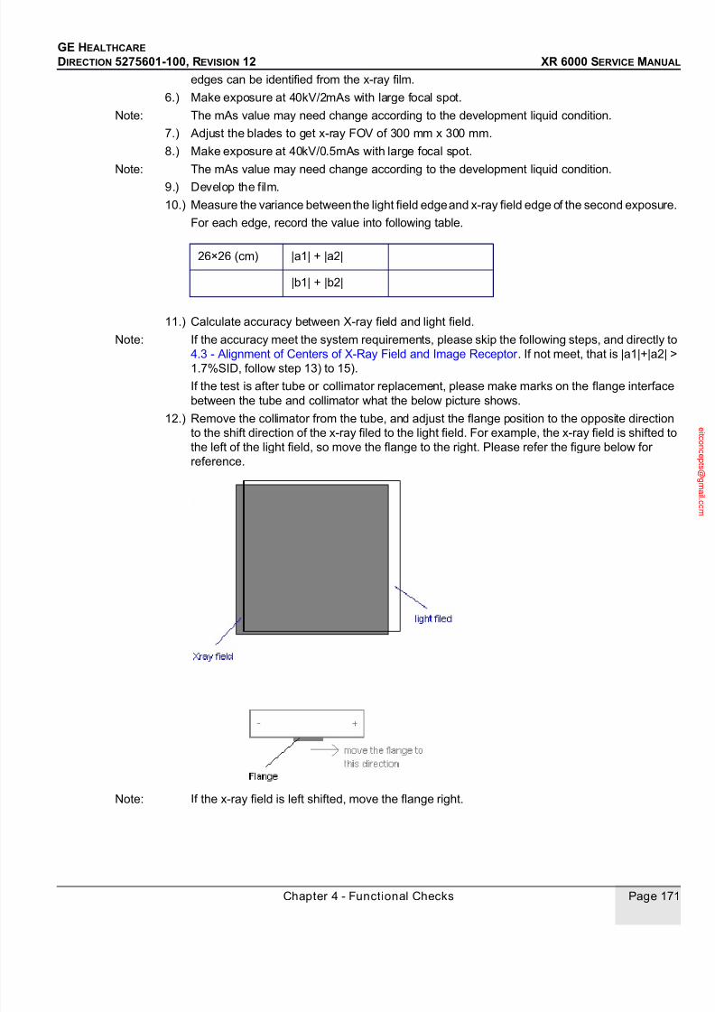
7/24/2019 GE XR6000 X-Ray - Service Manual
http://slidepdf.com/reader/full/ge-xr6000-x-ray-service-manual 171/421
GE HEALTHCARE
DIRECTION 5275601-100, REVISION 12 XR 6000 SERVICE MANUAL
Chapter 4 - Functional Checks Page 171
edges can be identified from the x-ray film.
6.) Make exposure at 40kV/2mAs with large focal spot.
Note: The mAs value may need change according to the development liquid condition.
7.) Adjust the blades to get x-ray FOV of 300 mm x 300 mm.
8.) Make exposure at 40kV/0.5mAs with large focal spot.
Note: The mAs value may need change according to the development liquid condition.
9.) Develop the film.
10.) Measure the variance between the light field edge and x-ray field edge of the second exposure.
For each edge, record the value into following table.
11.) Calculate accuracy between X-ray field and light field.
Note: If the accuracy meet the system requirements, please skip the following steps, and directly to
4.3 - Alignment of Centers of X-Ray Field and Image Receptor . If not meet, that is |a1|+|a2| >1.7%SID, follow step 13) to 15).
If the test is after tube or collimator replacement, please make marks on the flange interface
between the tube and collimator what the below picture shows.
12.) Remove the collimator from the tube, and adjust the flange position to the opposite direction
to the shift direction of the x-ray filed to the light field. For example, the x-ray field is shifted to
the left of the light field, so move the flange to the right. Please refer the figure below for
reference.
Note: If the x-ray field is left shifted, move the flange right.
26×26 (cm) |a1| + |a2|
|b1| + |b2|

7/24/2019 GE XR6000 X-Ray - Service Manual
http://slidepdf.com/reader/full/ge-xr6000-x-ray-service-manual 172/421
GE HEALTHCARE
DIRECTION 5275601-100, REVISION 12 XR 6000 SERVICE MANUAL
Page 172 Section 4.0 Performance Checks
Note: If the x-ray field is right shifted, move the flange left.
13.) Re-install the collimator to the moved flange, re-test the misalignment value between x-ray
field and light field.
14.) If the requirement |a1| + |a2| <= 1.7% SID and |b1| + |b2| <= 1.7% SID has been met, make
marks on the flange, spacer, and tube as below.
Note: Please oriente the collimator flange by referring to the thin and thick lines.
Figure 4-3 Make Thin Marks Inside
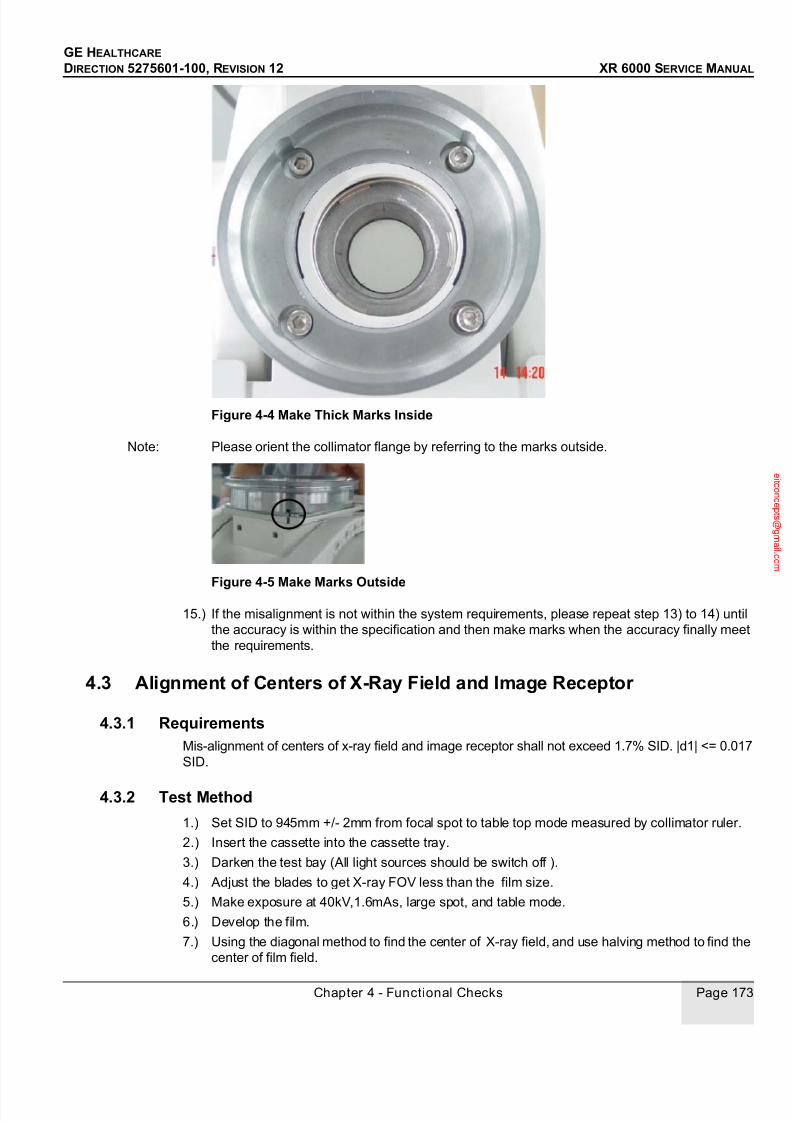
7/24/2019 GE XR6000 X-Ray - Service Manual
http://slidepdf.com/reader/full/ge-xr6000-x-ray-service-manual 173/421
GE HEALTHCARE
DIRECTION 5275601-100, REVISION 12 XR 6000 SERVICE MANUAL
Chapter 4 - Functional Checks Page 173
Figure 4-4 Make Thick Marks Inside
Note: Please orient the collimator flange by referring to the marks outside.
Figure 4-5 Make Marks Outside
15.) If the misalignment is not within the system requirements, please repeat step 13) to 14) until
the accuracy is within the specification and then make marks when the accuracy finally meet
the requirements.
4.3 Alignment of Centers of X-Ray Field and Image Receptor
4.3.1 RequirementsMis-alignment of centers of x-ray field and image receptor shall not exceed 1.7% SID. |d1| <= 0.017
SID.
4.3.2 Test Method
1.) Set SID to 945mm +/- 2mm from focal spot to table top mode measured by collimator ruler.
2.) Insert the cassette into the cassette tray.
3.) Darken the test bay (All light sources should be switch off ).
4.) Adjust the blades to get X-ray FOV less than the film size.
5.) Make exposure at 40kV,1.6mAs, large spot, and table mode.
6.) Develop the film.
7.) Using the diagonal method to find the center of X-ray field, and use halving method to find the
center of film field.

7/24/2019 GE XR6000 X-Ray - Service Manual
http://slidepdf.com/reader/full/ge-xr6000-x-ray-service-manual 174/421
GE HEALTHCARE
DIRECTION 5275601-100, REVISION 12 XR 6000 SERVICE MANUAL
Page 174 Section 4.0 Performance Checks
8.) Measure the distance between the two centers.
9.) Check whether it meets the requirement.
4.4 Image Quality
The Min resolution measured with following test method should be larger than 4lp/mm.
4.4.1 Test Method
1.) Set following exposure technique:
- 45kV;
- 4mAs;
- Small focus;
- SID = 100cm;
- 1cm thick plexiglass phantom;
- Resolution card.
2.) Put the resolution card onto the phantom, and put phantom on the center of the full FOV.
3.) Take exposure, develop the film.
4.) Put the film on a light box, maybe with the help of magnifying glass, read out the max resolution
of the film, verify the value is equal to or large than 4lp/mm.
After replace the tube or JEDI or some parts in JEDI, please do the tests below from 4.5 to 4.8.
Center of X-Ray Field
d1
Center of Cassette Film

7/24/2019 GE XR6000 X-Ray - Service Manual
http://slidepdf.com/reader/full/ge-xr6000-x-ray-service-manual 175/421
GE HEALTHCARE
DIRECTION 5275601-100, REVISION 12 XR 6000 SERVICE MANUAL
Chapter 4 - Functional Checks Page 175
4.5 Tube Voltage Accuracy
4.5.1 Tools A calibrated non-invasive kV meter of 2% accuracy or better. KV meter calibration value must be
inside the spec and must be in period of validity Or invasive Dynalyzer or equivalent.
4.5.2 RequirementsRange: 40kVp ~ 150kVp;
Minimum adjusting step: 1kV;
Accuracy: less than or equial to +/-(3%+2 kV+kV meter accuracy)
Note: If measurement with non-invasive kV meter failed, turn to Dynlayzer for accurate measurement.
4.5.3 Procedure
1.) System power up, select radiography mA at 200mA to 630mA, set 100ms, Large focal spot,
select exposure kV as following table.
2.) Take exposure with large spot and record the data of console display. The variance should be
met the requirement as above.
4.6 Tube Current
4.6.1 RequirementsRange: 10mA~630mA separate adjustment, 10.0, 12.5, 16.0, 20.0, 25.0, 32.0, 40.0, 50.0, 63.0,
80.0, 100.0, 125.0, 160.0, 200.0, 250.0, 320.0, 400.0, 500.0, 630.0;
Large Spot: 10~630mA;
Small Spot: 10~250mA;
Accuracy: less than or equal to +/-15%.
4.6.2 Procedure
1.) System power up, select three parameter mode (mA,kV,time) on system console. Manually
adjust exposure mA as following table, exposure at 150kV from 10 to 400mA, 80kV for 630mA,set 100ms exposure time.
2.) Take exposure by handle switch with Large Spot, record the data of console display.
Note: The mA used shall be minimum as allowed and mSec > 20.
Setting Value (kV) Test Data @ 200 mA Pass/Fail
40
80
150
Setting Value (kV) Test Data @ 80 kV Test Data @ 150 kV Pass/Fail
10 mA
200 mA

7/24/2019 GE XR6000 X-Ray - Service Manual
http://slidepdf.com/reader/full/ge-xr6000-x-ray-service-manual 176/421
GE HEALTHCARE
DIRECTION 5275601-100, REVISION 12 XR 6000 SERVICE MANUAL
Page 176 Section 4.0 Performance Checks
4.7 Exposure Time
4.7.1 RequirementsRange: 1.0ms~6300ms;
Separate adjustment: 1.0, 1.25, 1.6, 2.0, 2.5, 3.2, 4.0, 5.0, 6.3, 8.0, 10.0, 12.5, 16.0, 20.0, 25.0,
32.0, 40.0, 50.0, 63.0, 80.0, 100.0, 125.0, 160.0, 200.0, 250.0, 320.0, 400.0, 500.0, 630.0, 800,
1000, 1250, 1600, 2000, 2500, 3200, 4000, 5000, 6300;
Accuracy: less than or equal to +/-(10%+1ms).
4.7.2 Procedure
System power up, select radiography exposure parameter 80kV, 100mA. Take exposure andrecord the data of console display. The variance should be less than or equal to +/-(10%+1ms).
4.8 Exposure mAs
4.8.1 Requirements
Range: 0.5mAs~630mAs;Separate adjustment: 0.5, 0.63, 0.8, 1.0, 1.25, 1.6, 2.0, 2.5, 3.2, 4.0, 5.0, 6.3, 8.0, 10.0, 12.5, 16.0,
20.0, 25.0, 32.0, 40.0, 50.0, 63.0, 80.0, 100.0, 125.0, 160.0, 200.0, 250.0, 320.0, 400.0, 500.0, 630;
Accuracy: less than or equal to +/-(10%+0.2mAs).
4.8.2 Procedure
1.) System power up, select two-parameter exposure mode, and select the exposure mAs as
following table at 80kV.
2.) Take exposure and record the data of console display. The variance should be less than or
equal to +/-(10%+0.2mAs).
400 mA N/A
630 mA N/A
Setting Value (kV) Test Data @ 80 kV Test Data @ 150 kV Pass/Fail
Setting Time (ms) 10 500 6300
Test Data (ms)
Setting Value @ 80kV (mAs) Test Data (mAs) Pass/Fail
10
40
63
400 (type test)
630 (type test)
7/24/2019 GE XR6000 X-Ray - Service Manual
http://slidepdf.com/reader/full/ge-xr6000-x-ray-service-manual 177/421
GE HEALTHCARE
DIRECTION 5275601-100, REVISION 12 XR 6000 SERVICE MANUAL
Chapter 4 - Functional Checks Page 177
4.9 Automatic Exposure Control (AEC) - Optional
If table AEC or wall stand AEC is ordered, enable them through configuration screen of the console.
4.9.1 Table AEC
1.) Adjust the SID to 100 cm.
2.) Open the collimator.
3.) Select the large focal spot.
4.) Set 80 kV, 20 mAs backup, table mode, center cell of ion chamber selected, and take an
exposure.
5.) Check the exposure is terminated less than 5 mAs.
6.) Close the collimator.
7.) Select the large focal spot.
8.) Set 80 kV, 600 mAs, table mode, center cell of ion chamber selected, and take an exposure.
9.) Check that the exposure is interrupted after about 4 seconds, a buzzer will be heard, and the
inhibit indicator will light up.
10.) Check the exposure is terminated. The value is 600 mAs or less.
4.9.2 Wall Stand AEC
1.) Adjust the SID to 180 cm.
2.) Open the collimator.
3.) Select the large focal spot.
4.) Set 80 kV, 20 mAs backup, wall stand mode, center cell of ion chamber selected, and take an
exposure.
5.) Check the exposure is terminated less than 5 mAs.
6.) Close the collimator.
7.) Select the large focal spot.
8.) Set 80 kV, 600 mAs, wall stand mode, center cell of ion chamber selected, and take an
exposure.
9.) Check that the exposure is interrupted after about 4 seconds, a buzzer will be heard, and the
inhibit indicator will light up.
10.) Check the exposure is terminated. The value is 600 mAs or less.
Warm up or season the tube before exposures of high kV or mA can be taken appropriately.
4.10 Collimator Light Timer
Press the collimator light button and check that the light will go out automatically in more than 30
seconds.

7/24/2019 GE XR6000 X-Ray - Service Manual
http://slidepdf.com/reader/full/ge-xr6000-x-ray-service-manual 178/421
GE HEALTHCARE
DIRECTION 5275601-100, REVISION 12 XR 6000 SERVICE MANUAL
Page 178 Section 5.0 HHS Test
Section 5.0 HHS Test
Installers must indicate that the combination of installed HHS Certified Components is compatible
on Form F3382 provided in Direction 46-013894, System Field-Test For HHS.
Figure 4-6 System HHS Compliance Compatibility List
PRODUCT CATEGORY PRODUCT DESCRIPTION MODEL NUMBERX-RAY CONTROL SYSTEM CONSOLE 5183178
GEN. & PDU
X-RAY TUBE ASSEMBLYHOUSING (CASING)
Toshiba E7843X 5308337
BEAM LIMITING DEVICE Manual COLLIMATOR 5189248
CASSETTE TRAY CASSETTE TRAY

7/24/2019 GE XR6000 X-Ray - Service Manual
http://slidepdf.com/reader/full/ge-xr6000-x-ray-service-manual 179/421
Chapter 5 - JEDI GENERATOR THEORY AND FUNCTIONAL DESCRIPTION Page 179
GE HEALTHCARE
DIRECTION 5275601-100, REVISION 12 XR 6000 SERVICE MANUAL
Chapter 5 - JEDI GENERATOR THEORY AND
FUNCTIONAL DESCRIPTION
Section 1.0
Theory
1.1 Glossary
Glossary of terms used in this document:
Term Definition
ABC Automatic Brightness Control. Regulation loop which makes the
measured brightness equal to brightness demand
AEC Automatic Exposure Control. Exposure cut off technique which uses the
brightness signal to cut the exposure
CAN Controller Area Network. A network used for localized control.
CPU Control Processor Unit. Microprocessor and peripherals which run the
software/firmware
EPLD Erasable Programmable Logic Device.
EMC Electro Magnetic Compatibility. The EMC function prevents the generator
from polluting the power source.
FPGA Field Programmable Gate Array. It is programmed by the CPU core after
the reset and handles all the exposure control logic including the system
interface real-time lines.
HV RIPPLE High voltage variations due to inverter current pulses. Typically a few
percent.
STATEMACHINE
Software or hardware function which handles the state of a system and
authorize to go to the next state upon reception of specific events.
IGBT Insulated gate bipolar transistor. A type of power switch
Llp HV power inverter parallel resonant current; current in the parallel inductor
Llr HV power inverter serial resonant current; current in the serial inductor.
MOS Metal Oxide Semiconductor. A type of power switch
OGP On Gantry Processor. Unit which drives the generator in CT systems
PDU Power Distribution Unit
RMS Root Mean Square

7/24/2019 GE XR6000 X-Ray - Service Manual
http://slidepdf.com/reader/full/ge-xr6000-x-ray-service-manual 180/421
GE HEALTHCARE
DIRECTION 5275601-100, REVISION 12 XR 6000 SERVICE MANUAL
Page 180 Section 1.0 Theory
1.2 JEDI HIGH LEVEL BLOCK DIAGRAM
Figure 5-1 JEDI Generator / Functional Architecture
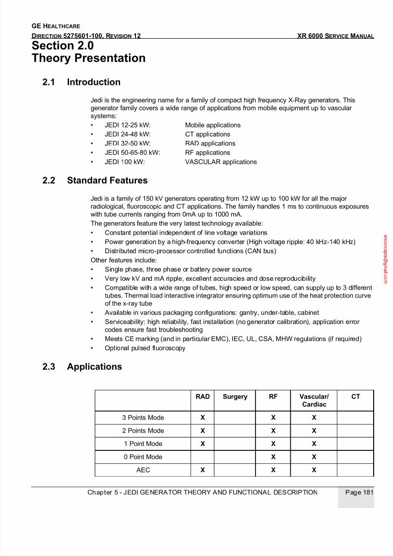
7/24/2019 GE XR6000 X-Ray - Service Manual
http://slidepdf.com/reader/full/ge-xr6000-x-ray-service-manual 181/421
Chapter 5 - JEDI GENERATOR THEORY AND FUNCTIONAL DESCRIPTION Page 181
GE HEALTHCARE
DIRECTION 5275601-100, REVISION 12 XR 6000 SERVICE MANUAL
Section 2.0 Theory Presentation
2.1 Introduction
Jedi is the engineering name for a family of compact high frequency X-Ray generators. This
generator family covers a wide range of applications from mobile equipment up to vascular
systems:
• JEDI 12-25 kW: Mobile applications
• JEDI 24-48 kW: CT applications
• JEDI 32-50 kW: RAD applications
• JEDI 50-65-80 kW: RF applications
• JEDI 100 kW: VASCULAR applications
2.2 Standard Features
Jedi is a family of 150 kV generators operating from 12 kW up to 100 kW for all the major
radiological, fluoroscopic and CT applications. The family handles 1 ms to continuous exposures
with tube currents ranging from 0mA up to 1000 mA.
The generators feature the very latest technology available:
• Constant potential independent of line voltage variations
• Power generation by a high-frequency converter (High voltage ripple: 40 kHz-140 kHz)
• Distributed micro-processor controlled functions (CAN bus)
Other features include:
• Single phase, three phase or battery power source
• Very low kV and mA ripple, excellent accuracies and dose reproducibility
• Compatible with a wide range of tubes, high speed or low speed, can supply up to 3 different
tubes. Thermal load interactive integrator ensuring optimum use of the heat protection curve
of the x-ray tube
• Available in various packaging configurations: gantry, under-table, cabinet
• Serviceability: high reliability, fast installation (no generator calibration), application error
codes ensure fast troubleshooting
• Meets CE marking (and in particular EMC), IEC, UL, CSA, MHW regulations (if required)
• Optional pulsed fluoroscopy
2.3 Applications
RAD Surgery RF Vascular/Cardiac
CT
3 Points Mode X X X
2 Points Mode X X X
1 Point Mode X X X
0 Point Mode X X
AEC X X X

7/24/2019 GE XR6000 X-Ray - Service Manual
http://slidepdf.com/reader/full/ge-xr6000-x-ray-service-manual 182/421
GE HEALTHCARE
DIRECTION 5275601-100, REVISION 12 XR 6000 SERVICE MANUAL
Page 182 Section 2.0 Theory Presentation
Legend:
• AEC - Automatic Exposure Control
• AET - Automatic Tomographic Exposure
• ABC - Automatic Brightness Control in fluoroscopy
2.4 Architecture
Refer to Illustration 19: Jedi Generator / Functional Architecture
The Jedi family is composed of 3 elements:
2.4.1 A Kernel• High voltage chain composed of kV control, HV power inverter and HV tank
• Anode rotation function• Tube filaments heater function
• Control bus for communication between the functions
• DC bus for power distribution to each function
• Input voltage to DC conversion: AC/DC function
• Low voltage power supply
• Application software, running on the kV control board
These functions are the Jedi core. They are present in all versions of the generator.
A function can be unique for all products, or can have several different releases based on product
specification.
Example: The anode rotation function is available in 2 releases:
• low speed rotation for applications where the tube has a max rotation of 3000 rpm
• high speed/low speed rotation for applications where at least one of the tubes can use 8000-
10000 rpm
The control bus is unique.
2.4.2 Options Depending on the Application• A System Interface which can be:
- CT interface
- RAD interface (console interface, room interface, AEC management present or not)
- ATLAS interface
Tomography X X
AET X X
Continuous/Pulsed
Fluoroscopy
X X X
Rad Exposures XCinema 30 fr/s X
Cinema 90 fr/s X
ABC X X
Variable mA Scans X
Low mA Fluoroscopy X

7/24/2019 GE XR6000 X-Ray - Service Manual
http://slidepdf.com/reader/full/ge-xr6000-x-ray-service-manual 183/421
Chapter 5 - JEDI GENERATOR THEORY AND FUNCTIONAL DESCRIPTION Page 183
GE HEALTHCARE
DIRECTION 5275601-100, REVISION 12 XR 6000 SERVICE MANUAL
• EMC function
• Grid function (RF, vascular)
• Bias function (RF, vascular)
• Tube management (2 tubes or 3 tubes option)
Figure 5-2 JEDI Generator / Functional Architecture
7/24/2019 GE XR6000 X-Ray - Service Manual
http://slidepdf.com/reader/full/ge-xr6000-x-ray-service-manual 184/421
GE HEALTHCARE
DIRECTION 5275601-100, REVISION 12 XR 6000 SERVICE MANUAL
Page 184 Section 2.0 Theory Presentation
2.5 A Packaging Architecture
The packaging architecture consists in a set of boxes which can be put together in several ways to
make Jedi fit either in a cabinet, or a console foot, or a table foot. The boxes can also be split in 2
units distant of several meters (example: CT gantry). Refer to Illustration 20.
The boxes normally consist of the following:
2.5.1 Auxiliaries Box• Rotation function
• Heater function
• Low voltage power supply (which can also be in the AC/DC box)
This box is always present.
2.5.2 Power Box• HV tank
• HV power inverter
• kV control• System interface (for the less complex system interface)
This box is always present.
2.5.3 AC/DC Box• MC filter (optional)
• AC/DC function
• Low voltage power supply (which can also be in the auxiliaries box)
This box is always present.
2.5.4 System Interface Box• RAD interface
• AEC interface
This box is present in the RAD product.
2.5.5 Optional Boxes• Tube selection
• Grid/Bias control

7/24/2019 GE XR6000 X-Ray - Service Manual
http://slidepdf.com/reader/full/ge-xr6000-x-ray-service-manual 185/421
Chapter 5 - JEDI GENERATOR THEORY AND FUNCTIONAL DESCRIPTION Page 185
GE HEALTHCARE
DIRECTION 5275601-100, REVISION 12 XR 6000 SERVICE MANUAL
Figure 5-3 JEDI Generator / Packaging Architecture
AC/DCBoard
EMC Filter
(Optional)
HV Tank
KV Control
Board
CTInterface
Gate Board
Tube
HV
Inverter
RectifierBlock
KV Measure
Dual Snub
+ -
Power Box AC/DC Box
Auxiliaries
Box
System Interface
Box for the radproduct
Optional
Boxes
Heater Board
RotationBoard
LVPS Board(for NP andEmperor)
RotationCapacitor
RotationCapacitor
RADInterface
AECInterface
TubeSelection
Grid/Bias Control
LVPS Board(for TIGER)
(optional)

7/24/2019 GE XR6000 X-Ray - Service Manual
http://slidepdf.com/reader/full/ge-xr6000-x-ray-service-manual 186/421
GE HEALTHCARE
DIRECTION 5275601-100, REVISION 12 XR 6000 SERVICE MANUAL
Page 186 Section 3.0 Technique Factors Measurement Criteria
Section 3.0 Technique Factors Measurement Criteria
3.1 kV Accuracies
JEDI emperor: Generator 50kW
Definition: accuracy between operator selection and the peak kV during the exposure.
Radiography:
40kV~150kV range: +/- 3%+/-2kV
3.2 mA Accuracies
JEDI emperor: Generator 50kW
Definition: accuracy between operator selection and the real mean mA during the exposure
(characterized by real kV>75% of the operator selection).
Radiography:
exposures shorter than 40ms (=mA loop setting time): +/- 10%+/-1mA
exposures longer than 40ms (=mA loop setting time): +/- 5%+/-1mA
3.3 mAs Accuracies
JEDI emperor: Generator 50kW
Two accuracies have to be defined: one in 3 point Mode, one in 2 point Mode.
1/3 point Mode
Definition: accuracy between operator selection (mA and ms) and the real mAs during the exposure
(characterized by real kV>75% of the operator selection).Radiography:
exposures shorter than 40ms (=mA loop setting time): +/- 15%+/-0.1mAs
exposures longer than 40ms (=mA loop setting time): +/- 10%+/-0.1mAs
2/2 point Mode
Definition: accuracy between the internal mAs measure displayed after the exposures on the
operator console and the real mAs during the exposure (characterized by real kV>75% of the
operator selection).
Note: mAs measure is also called postdisplayed.
Radiography, manual mode:
exposures shorter than 40ms (=mA loop setting time): +/- 5%+/-0.1mAsexposures longer than 40ms (=mA loop setting time): +/- 5%+/-0.1mAs
3.4 Exposure Time Accuracies
JEDI emperor: Generator 50kW
Time accuracy (3 point Mode)
Definition: accuracy between operator selection and real exposure time (characterized by real
kV>75% of the operator selection).
Radiography:
+/- 5%+/-0.5ms

7/24/2019 GE XR6000 X-Ray - Service Manual
http://slidepdf.com/reader/full/ge-xr6000-x-ray-service-manual 187/421
Chapter 6 - Exception Handling And Error Codes Page 187
GE HEALTHCARE
DIRECTION 5275601-100, REVISION 12 XR 6000 SERVICE MANUAL
Chapter 6 - Exception Handling And Error
Codes
Section 1.0
Exception Handling
JEDI software performs auto-test at power up and continuously monitors the correct operation of its
functions during application. Any malfunction is stored in the JEDI error log. Errors found can only
be reported if the generator is powered on and functional.
1.1 Diagnostics
There are different levels of diagnostics.
1.2 Power-On Diagnostic
At power-up the kV control performs its own initialisation, checks its memory integrity (checksum of
program and NVRAM) and starts the communication with its peripherals as well as the system.
Communication is permanently checked afterwards. It then initialises the Rotation board and
Heater board with their respective database parameters and loads kV control FPGA.
Eight LEDs (S7..S0) on the kV control board show the software status.
During power-on, the Heater board and the Rotation board CPUs are initialised and check their
memory integrity and hardware. If a problem is encountered, a PRD error is reported to the kV
control.
1.3 Live Diagnostics
1.) Under application faults will be reported through an error code on the Service Laptop. Some
are straightforward and convey the root cause. Refer to the recommended action in the error
list.
2.) Diagnostics run separately:
- heating function
- rotation function
- inverter gate command diagnostic
- inverter in short circuit diagnostic
- no load HV fucntion diagnostics3.) Manual Diagnostics
Through a troubleshooting guide based on an error message or when the generator does not
reply.
1.4 Error Code Structure
The error code structure described in this chapter applies to JEDI error detection and logging. The
JEDI error log file can be accessed from the system through the system console or a laptop (JEDI
error log upload functionality).

7/24/2019 GE XR6000 X-Ray - Service Manual
http://slidepdf.com/reader/full/ge-xr6000-x-ray-service-manual 188/421
GE HEALTHCARE
DIRECTION 5275601-100, REVISION 12 XR 6000 SERVICE MANUAL
Page 188 Section 1.0 Exception Handling
When an error is detected, it is logged in the JEDI error log file. The file contains a maximum of sixty
four error logs.
Each log shows the following structure:
The fields are described in the following paragraphs.
1.5 Simplified Error Code Definition
The simplified error code is a grouping of the JEDI error codes. This field gives a rapid
understanding of which part of JEDI is faulty.
1.6 Generator Phase Definition
The generator phase field contains the state of the generator when the er ror occur red.
1.7 Error Class Definition
There are five classes of errors that correspond to different levels of impact to the system. The class
of errors correspond to the seriousness of the errors.
Simplified
error code
Generator
Phase
Error
Class
Error
Code
Data associated
with the error code
Number of
occurrences
Date &
time
SimplifiedError Code
Description
30 Tube spits errors
40 Rotation errors
50 Heater errors
60 Exposure errors (HV inverter + mA measure + exposure control
70 Power supply errors (low voltage + DC bus)Hardware errors (internalcommunications + cables)
80 Hardware errors (internal communications + cables)
90 Application errors (saved RAM + software)
100 External communication errors
110 Thermal errors
120 Manipulation error
10 Rotation warnings (engineering use)
20 Heater warnings (engineering use)
25 LVPS warnings (engineering use)
27 Application warnings (mainly saved RAM battery change)
GeneratorPhase
Description
0 idle: entered in diagnostic mode
1 powered up; waiting for configuration
2 Stand by: configuration completed, waiting for a preparation command
3 Preparation in progress: JEDI gets ready to take X-rays
4 Ready for exposures (rotation at speed; filament; HV inverter drive ready; noerrors): waiting for an exposure command
5 High voltage on
6 Error detected and not yet cleared
Class Description

7/24/2019 GE XR6000 X-Ray - Service Manual
http://slidepdf.com/reader/full/ge-xr6000-x-ray-service-manual 189/421
Chapter 6 - Exception Handling And Error Codes Page 189
GE HEALTHCARE
DIRECTION 5275601-100, REVISION 12 XR 6000 SERVICE MANUAL
1.8 Error Code Definition
Each error code comprises two fields (which cannot be generated and used separately);
• the first field describes the JEDI function which is faulty (referred to as the function code)
• the second field describes the error detected.
Example: error code 0306 means:
• 03: high voltage generation function;
• 06: no kV feedback on anode.
Function Codes List
1 Errors which have no impact on the system operation.
Errors detected in background diagnostics during application. They are referred as "Warning"
errors,
to monitor drifts and used for engineering tracking.
The generator phase remains unchanged.
Errors are stored in the JEDI error log.
2 Errors which are detected by JEDI and that are recoverable automatically without noticeableeffect
on the system, such as error related to recovered tube spits.
The generator phase remains unchanged.
Errors which usually occur during exposure.
3 Errors detected by JEDI during exposure. They stop the exposure and revert the generator into
a safe state.
Error will be reset on Exposure Command release. It will require another Exposure Command to
restart the sequence.
The generator phase is set to "error" until the error is cleared.
4 Errors which are related to any hardware failures, software application or communication errors.
JEDI will revert to a safe state.If preparation is in progress, it is stopped.
Errors are cleared either by a reset error action from the system (for system having a reset error
mechanism) or by a prep release or by a new prep command.
The generator phase is set to "error" until ther error is cleared.
Application cannot work if errors are persistent.
5 These codes may appear when the generator or tube temperature limits are reached.
The application waits until the thermal information disappears. The error information is
temporary.
The generator phase is set to "error" until the error is cleared.
FunctionCode
Description
01 Rotation
02 heater
03 High voltage generation
04 mA control
05 Power supplies
06 System interface
07 Software
08 Application
09 Tube control

7/24/2019 GE XR6000 X-Ray - Service Manual
http://slidepdf.com/reader/full/ge-xr6000-x-ray-service-manual 190/421
GE HEALTHCARE
DIRECTION 5275601-100, REVISION 12 XR 6000 SERVICE MANUAL
Page 190 Section 2.0 Error Codes, Diagnostics & Troubleshooting
1.9 Data Associated With The Error Code
The field "data associated with the error code" shows detailed information over the state of the
generator when the error occurred.
Example: Rotation high speed acceleration state, small focus preheat, tube number 1 selected.
1.10 Number Of Occurrences
The field "number of occurrences" is used to log the same error occurring several times
consecutively. Instead of filling the error log file with the same error which has occurred
consecutively several times, the first error is logged and successive errors are recorded through
increasing the "number of occurrences" field.
1.11 Date & Time
The field "date & time" stores the date and time when the error occurred. This is the JEDI internal
date and time which may be different from the system date and time. In the case of logging the same
error the date/time is of the most recent entry.
Section 2.0
Error Codes, Diagnostics & Troubleshooting
2.1 Introduction
This diagnostics section is to introduce the JEDI generator with the following information:
• Power-On diagnostics LED indication.
• List all the potential error codes that can be issued by JEDI Generator.
• Provide error code explanation, potential cause and recommended action.
• List of diagnostics aids and explanation of diagnostics.
2.2 Power On Diagnostics
Refer to theory of operation for power-on sequence. This paragraph in this section is to providemeaning of boards' LED status. The LED display status is offering useful information at a glance to
proceed to error code based troubleshooting. Whenever in doubt, a simple step is to watch the LED
status display on the kV control board, then the Rotation and Heater.
kV control LED status:
• During Power On Diagnostics
10 Tube management
11 Grid
12 Bias
13 AEC
14 Hardware

7/24/2019 GE XR6000 X-Ray - Service Manual
http://slidepdf.com/reader/full/ge-xr6000-x-ray-service-manual 191/421
Chapter 6 - Exception Handling And Error Codes Page 191
GE HEALTHCARE
DIRECTION 5275601-100, REVISION 12 XR 6000 SERVICE MANUAL
The 8 LED's (S0...S7) are lit successively in both directions (Scrolling as indicated by the
arrows): the power up diagnostics are completed, kV control board is up and running.
One out of two is lit: Data base checksum problem. An error code is logged. Refer to error code
description.
S7, S6, S5 are lit along with either S0 or S1 or S2 (depending of the type of FPGA downOne
out of two is lit: Data base checksum problem. An error code is logged. Refer to error code
description.
• When an application error occurs (Not PRD)
The simplified error code is displayed on the Leds. They blink; when the error is cleared (by a
return to the standby mode for example), the 8 LEDs are lit successively.
Heater board LED status: (See central listing)
After the power on diagnostics, heater board LEDs DS1 and DS2 are lit successively. Any
different status correspond to an abnormal situation. An error code is logged. Refer to error
code description.
Rotation board LED status: (See central listing)
After the power on diagnostics, rotation board LED DS5 is blinking. Any different status
correspond to an abnormal situation. An error code is logged. Refer to error code description.
2.3 Error Code List
The error code list and associated short description is presented below.
kV control board
S0..................S7
_ o o o o
S0.........................S7
S0.....................S7
o o o o
o o o
S0.....................S7
e.g: No communication
Simplified
Error Code
Description ErrorClass ErrorCode Description
30 Tube Spits 2 0301H Tube spit (kV+ and kV- dropped)
2 0302H Tube spit (kV+ has dropped)

7/24/2019 GE XR6000 X-Ray - Service Manual
http://slidepdf.com/reader/full/ge-xr6000-x-ray-service-manual 192/421
GE HEALTHCARE
DIRECTION 5275601-100, REVISION 12 XR 6000 SERVICE MANUAL
Page 192 Section 2.0 Error Codes, Diagnostics & Troubleshooting
2 0303H Tube spit (kV- has dropped)
2 0304H Tube spit (kV regulation error)
2 0305H FPGA problem (restarting safety signal)
40 Rotation
Error
4 0101H No CAN message received within 5 secs
4 0102H Database not correct
4 0103H Rotation current overload
4 0104H Rotation Openload
4 0105H Rotation Phases unbalanced
4 0106H Rotation Phases error
4 0107H Rotation Inverter permanent overcurrent
4 0108H Rotation command error
4 0109H MAINS_DROP has failed
4 0110H PRD error
4 0111H F0 main frequency problem4 0149H Unknown Rotation error
50 Heater Error 4 0201H No CAN message received within 5 secs
4 0203H Heater inverter permanent overcurrent
4 0204H Filament permanent open circuit
4 0205H Heater Inverter permanent short circuit
4 0206H Filament too high for Pre-heat
4 0207H Filament too high for Pre-heat
4 0208H Filament too high for Heat
4 0209H Heater command error
4 0210H Current under estimated fork
4 0211H Current over estimated fork
4 0212H MAINS_DROP detected
4 0213H PRD error
4 0214H Stay too long in Boost
4 0215H Filament selection error
4 0216H Measured current while inverter OFF
4 0221H
0222H
0223H
0224H
Filament Database not correct
4 0248H
0249H
Unknown Heater error
60 Exposure
errors
3 0306H No kV Feedback on anode
3 0307H No kV Feedback on cathode
3 0308H No kV Feedback on anode and cathode
3 0309H kV detected during kV diag
3 0310H kV max detected
3 0311H ILP current not OK
3 0312H ILR current not OK
Simplified
Error Code
Description ErrorClass ErrorCode Description
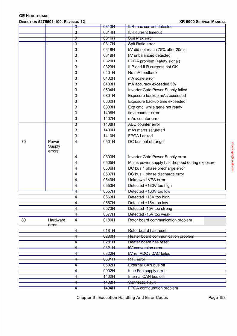
7/24/2019 GE XR6000 X-Ray - Service Manual
http://slidepdf.com/reader/full/ge-xr6000-x-ray-service-manual 193/421
Chapter 6 - Exception Handling And Error Codes Page 193
GE HEALTHCARE
DIRECTION 5275601-100, REVISION 12 XR 6000 SERVICE MANUAL
3 0313H ILR max current detected
3 0314H ILR current timeout
3 0316H Spit Max error
3 0317H Spit Ratio error
3 0318H kV did not reach 75% after 20ms
3 0319H kV unbalanced detected
3 0320H FPGA problem (safety signal)
3 0323H ILP and ILR currents not OK
3 0401H No mA feedback
3 0402H mA scale error
3 0403H mA accuracy exceeded 5%
3 0504H Inverter Gate Power Supply failed
3 0801H Exposure backup mAs exceeded
3 0802H Exposure backup time exceeded
3 0803H Exp cmd while gene not ready
3 1406H time counter error
3 1407H mAs counter error
3 1408H AEC counter error
3 1409H mAs meter saturated
3 1410H FPGA Locked
70 Power
Supply
errors
4 0501H DC bus out of range
4 0503H Inverter Gate Power Supply error
4 0505H Mains power supply has dropped during exposure
4 0506H DC bus 1 phase precharge error
4 0507H DC bus 1 phase discharge error
4 0549H Unknown LVPS error
4 0553H Detected +160V too high
4 0557H Detected +160V too low
4 0563H Detected +15V too high
4 0567H Detected +15V too low
4 0573H Detected -15V too strong
4 0577H Detected -15V too weak
80 Hardware
error
4 0180H Rotor board communication problem
4 0181H Rotor board has reset
4 0280H Heater board communication problem
4 0281H Heater board has reset
4 0321H kV conversion error
4 0322H kV ref ADC / DAC failed
4 0601H RTL error
4 0602H External CAN bus off
4 0902H tube Fan supply error
4 1402H Internal CAN bus off
4 1403H Connectic Fault
4 1404H FPGA configuration problem

7/24/2019 GE XR6000 X-Ray - Service Manual
http://slidepdf.com/reader/full/ge-xr6000-x-ray-service-manual 194/421
GE HEALTHCARE
DIRECTION 5275601-100, REVISION 12 XR 6000 SERVICE MANUAL
Page 194 Section 2.0 Error Codes, Diagnostics & Troubleshooting
4 1405H Tank sensor problem
90 Application
errors
4 0701H Saved RAM checksum pb
4 0702H Software problem
4 0703H Watchdog reset has just occurred
4 0704H Rotor/Heater hold too long
100 Communication errors
4 0603H Debug screen com error
4 0604H Database download error
4 0605H TAV communication error
4 0606H MPC/Madrid communication error
4 1301H AEC communication error
110 Thermal
error
5 0804H Tank Thermal Error
5 0903H Tube exceeded 70degC
120 Manipulatio
n error
5 1500H Tomo brightness error
5 1501H Exposure switch released during exposure
5 1502H AEC cut off error
10 Rotor
Warning
1 0151H CAN Domain command number error
1 0152H CAN Domain request with no transfer init
1 0153H CAN Domain Toggle bit error
1 0154H CAN Domain : less than 2 data to download
1 0155H CAN Domain Abort received & applied
1 0156H Bad index in config upload
1 0157H Tube switch while rotor not off
1 0158H Acceleration cmd while no tube selected1 0159H Acceleration cmd while database not OK
1 0160H Database download while rotor speeding
1 0161H Acceleration command not OK
1 0162H Rotor acceleration while in error
1 0163H No CAN message received within 4 secs
1 0164H Rotation Inverter overcurrent (< 3 times)
1 0199H Unknown rotation warning
20 Heater
Warning
1 0251H Received command is not OK
1 0252H Heater command not OK
1 0253H No CAN message received within 4 secs
1 0254H Heater inverter overcurrent
(inverter1) (<3 times)
1 0255H Filament open circuit (inverter1) (<3 times)
1 0256H Heater Inverter short circuit (inverter1) (<3times)
1 0257H Tube switch while filaments not OFF
1 0258H CAN Domain command number error
1 0259H CAN Domain request with no transfer init
1 0260H CAN Domain Toggle bit error

7/24/2019 GE XR6000 X-Ray - Service Manual
http://slidepdf.com/reader/full/ge-xr6000-x-ray-service-manual 195/421
Chapter 6 - Exception Handling And Error Codes Page 195
GE HEALTHCARE
DIRECTION 5275601-100, REVISION 12 XR 6000 SERVICE MANUAL
2.4 Error Reporting
The control console only displays the simplified error code from the Jedi generator.
Whenever a generator error is displayed on the operator console, the Jedi errorlog upload
functionality is available to get more detailed information about the error .This function is performed
from the service laptop.
The simplified error code is used to find the Jedi error code in the Jedi errorlog file.
With this information, look at the Jedi trouble shooting table to find the FRU to replace.
2.5 Diagnostics
This chapter describes diagnostics tools based on error codes and specific diagnostics.
Before any manual intervention, ensure the main power is off. Apply lock out-tag out procedure for
your own safety when manipulating inside the equipment is required.
2.6 Detailed Error Description & Troubleshooting Guide
The table below provides guidelines to troubleshoot Generator problems based on error code.
For each code, there is:
• Associated message and additional explanation related to the error occurrence.
• List potential cause, in the order of expected probability.
• Recommended action, with, in some cases, link to some more information as indicated where
cases apply, such as to run some specific diagnostics.
Codes are sorted by ascending order both for simplified code and error code.
Refer to the theory of operation for error code structure.
Information about associated data structure is located at the end of each error code subset
whenever it applies.
Whenever wiring, cabling, LED check is mentioned in the recommended actions, refer to the central
listing or to Illustration 1.
1 0261H CAN Domain : less than 2 data to download
1 0262H CAN Domain Abort received & applied
1 0263H Database download while heater not cut
1 0299H Unknown Heater warning
25 Low Voltage
Power
supplyWarnings
1 0550H No more warn +160V too low or too gigh
1 0551H Detected +160V too high
1 0555H Detected +160V too low
1 0560H No more warn +15V too low or too high
1 0561H Detected +15V too high
1 0565H Detected +15V too low
1 0570H No more warn -15V too low or too high
1 0571H Detected -15V too strong
1 0575H Detected -15V too weak
1 0599H Unknown LVPS warning27 Application
warnings
1 1401H Saved RAM power supply limit reached

7/24/2019 GE XR6000 X-Ray - Service Manual
http://slidepdf.com/reader/full/ge-xr6000-x-ray-service-manual 196/421
GE HEALTHCARE
DIRECTION 5275601-100, REVISION 12 XR 6000 SERVICE MANUAL
Page 196 Section 2.0 Error Codes, Diagnostics & Troubleshooting
Figure 6-1 JEDI Visual Power Supply Distribution for XR 6000
*
*
*
*
*
*
L E D s
I N V E R T E R . & L L C . C i r c u i t D
S 3 0 0
D C
b u s , 4 0 0 . . . 8 0 0 V
N e o n ' s
D
C
b u s , 4 0 0 . . . 8 0 0 V
D S 2
D S 1
D S 3
D S 1 ,
2
- 1 5 V , + 1 5 V
G a t e C o m m
a n d B o a r d
k V c t r l
R o t o r
B o a r d
E M C
F l t .
I / F
P D U
- 1 5 V
+ 1 5 V
" V C C " : + 5 V
3 p h , 3 8 0 - 4 8 0 V A C
A C / D C
D S 1
+
M
-
F 1
+
-
N E 1 H
e a t e r B o a r d
D S 3 , 2 ,
1
L V P
S
D C
b u s , 1 6 0
( 1 2 0 t o 2 0 0 V )
D S 7
+ 5 , - 1 5 , + 1 5
- 1 5 V
+ 1 5 V
C B 1
P U P T -
o r D S 7 -
6
*
A E C
N 1 ( 2 3 0 V )
C o n s o l e
K 1 -
1 5 V
+ 1 5 V
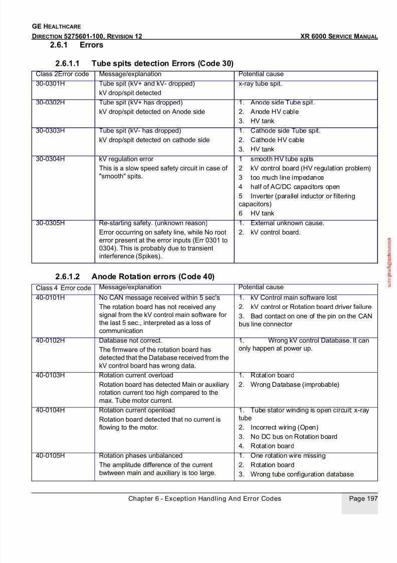
7/24/2019 GE XR6000 X-Ray - Service Manual
http://slidepdf.com/reader/full/ge-xr6000-x-ray-service-manual 197/421
Chapter 6 - Exception Handling And Error Codes Page 197
GE HEALTHCARE
DIRECTION 5275601-100, REVISION 12 XR 6000 SERVICE MANUAL
2.6.1 Errors
2.6.1.1 Tube spits detection Errors (Code 30)
2.6.1.2 Anode Rotation errors (Code 40)
Class 2Error code Message/explanation Potential cause
30-0301H Tube spit (kV+ and kV- dropped)
kV drop/spit detected
x-ray tube spit.
30-0302H Tube spit (kV+ has dropped)
kV drop/spit detected on Anode side
1. Anode side Tube spit.
2. Anode HV cable
3. HV tank
30-0303H Tube spit (kV- has dropped)
kV drop/spit detected on cathode side
1. Cathode side Tube spit.
2. Cathode HV cable
3. HV tank
30-0304H kV regulation error
This is a slow speed safety circuit in case of
"smooth" spits.
1 smooth HV tube spits
2 kV control board (HV regulation problem)
3 too much line impedance
4 half of AC/DC capacitors open
5 Inverter (parallel inductor or filteringcapacitors)
6 HV tank
30-0305H Re-starting safety. (unknown reason)
Error occurring on safety line, while No root
error present at the error inputs (Err 0301 to
0304). This is probably due to transient
interference (Spikes).
1. External unknown cause.
2. kV control board.
Class 4 Error code Message/explanation Potential cause
40-0101H No CAN message received within 5 sec's
The rotation board has not received any
signal from the kV control main software for
the last 5 sec., interpreted as a loss of
communication
1. kV Control main software lost
2. kV control or Rotation board driver failure
3. Bad contact on one of the pin on the CAN
bus line connector
40-0102H Database not correct.
The firmware of the rotation board has
detected that the Database received from the
kV control board has wrong data.
1. Wrong kV control Database. It can
only happen at power up.
40-0103H Rotation current overload
Rotation board has detected Main or auxiliary
rotation current too high compared to themax. Tube motor current.
1. Rotation board
2. Wrong Database (improbable)
40-0104H Rotation current openload
Rotation board detected that no current is
flowing to the motor.
1. Tube stator winding is open circuit: x-ray
tube
2. Incorrect wiring (Open)
3. No DC bus on Rotation board
4. Rotation board
40-0105H Rotation phases unbalanced
The amplitude difference of the current
bwtween main and auxiliary is too large.
1. One rotation wire missing
2. Rotation board
3. Wrong tube configuration database
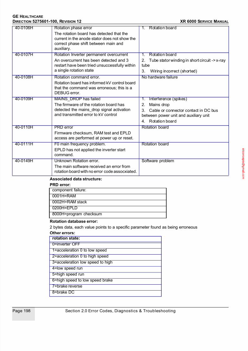
7/24/2019 GE XR6000 X-Ray - Service Manual
http://slidepdf.com/reader/full/ge-xr6000-x-ray-service-manual 198/421
GE HEALTHCARE
DIRECTION 5275601-100, REVISION 12 XR 6000 SERVICE MANUAL
Page 198 Section 2.0 Error Codes, Diagnostics & Troubleshooting
Associated data structure:
PRD error:
Rotation database error:
2 bytes data, each value points to a specific parameter found as being erroneous
Other errors:
40-0106H Rotation phase error
The rotation board has detected that the
current in the anode stator does not show the
correct phase shift between main and
auxiliary.
1. Rotation board
40-0107H Rotation Inverter permanent overcurrent
An overcurrent has been detected and 3restart have been tried unsuccessfully within
a single rotation state
1. Rotation board
2. Tube stator winding in short circuit -> x-raytube
3. Wiring incorrect (shorted)
40-0108H Rotation command error.
Rotation board has informed kV control board
that the command was erroneous; this is a
DEBUG error.
No hardware failure
40-0109H MAINS_DROP has failed
The firmware of the rotation board has
detected the mains_drop signal activation
and transmitted error to kV control
1. Interference (spikes)
2. Mains drop
3. Cable or connector contact in DC bus
between power unit and auxiliary unit
4. Rotation board40-0110H PRD error
Firmware checksum, RAM test and EPLD
access are performed at power up or reset.
Rotation board
40-0111H F0 main frequency problem.
EPLD has not applied the inverter start
command.
Rotation board
40-0149H Unknown Rotation error.
The main software received an error from
rotation board with no error code assocxiated.
Software problem
component failure:
0001H=RAM
0002H=RAM stack
0200H=EPLD
8000H=program checksum
rotation state:
0=inverter OFF1=acceleration 0 to low speed
2=acceleration 0 to high speed
3=acceleration low speed to high
4=low speed run
5=high speed run
6=high speed to low speed brake
7=brake reverse
8=brake DC

7/24/2019 GE XR6000 X-Ray - Service Manual
http://slidepdf.com/reader/full/ge-xr6000-x-ray-service-manual 199/421
Chapter 6 - Exception Handling And Error Codes Page 199
GE HEALTHCARE
DIRECTION 5275601-100, REVISION 12 XR 6000 SERVICE MANUAL
2.6.1.3 Filament Heater errors (Code 50)Class4 Error code Message/explanation Potential cause
50-0201H No CAN message received within 5 sec's
The Heater board has not received any
command from the kV control main software
for the last 5 sec., interpreted as a loss of
communication
1. kV Control main software lost
2. kV control or Heater board driver failure
3. Bad contact on one of the pin on the CAN
bus line connector
50-0203H Heater inverter permanent overcurrent. (SW
limit)
Issued by the heater board when an
overcurrent has been detected and 3 restarts
have been tried without success within 100
ms
1. Heater board
50-0204H Filament permanent open circuit.
Issued by the heater board when an open has
been detected and 3 restarts have been tried
without success within 100 ms
1. X-ray tube filament open
2. Heater to HV tank cable
3. Cathode HV cable or pin contacts
4. Open circuit in filament transformer inside
HV Tank.50-0205H Heater Inverter permanent short circuit (HW
limit)
Issued by the heater board when a short
circuit has been detected and 3 restarts have
been tried without success within 100 ms
1. Heater board
50-0206H Filament current too high on inverter 1 for
"Pre-Heat"
This is the result of an integrated value of the
RMS current measurement on Heater board
comparison with max. Tube value in
Database.
1. Tube Database or calibration
2. Heater board
50-0207H Filament current too high on inverter 1 for"Boost"
Same as above
1. Tube Database or calibration
2. Heater board
50-0208H Filament current too high on inverter 1 for
"Heat"
Same as above
1. Tube Database or calibration
2. Heater board
50-0209H Heater command error
Heater board has informed kV control board
that the command was erroneous; this is a
DEBUG error.
No hardware failure
50-0210H Current under estimated fork/range
RMS filament current measurement (every0.5 msec.) on heater board is too high
Heater board
50-0211H Current under estimated fork range
RMS filament current measurement (every
0.5 msec.) on heater board is too low
1. Open circuit
2. Heater board
50-0212H MAINS_DROP detected.
The firmware of the Heater board has
detected the mains_drop signal activation
and has transmitted error to kV control
1. Interference (spikes)
2. Mains drop
3. Cable or connector contact in DC bus
between AC/DC and auxiliary unit4
. Heater board

7/24/2019 GE XR6000 X-Ray - Service Manual
http://slidepdf.com/reader/full/ge-xr6000-x-ray-service-manual 200/421
GE HEALTHCARE
DIRECTION 5275601-100, REVISION 12 XR 6000 SERVICE MANUAL
Page 200 Section 2.0 Error Codes, Diagnostics & Troubleshooting
Associated data structure:PRD error :
Filament database error:2 bytes bitmap (LSByte=small focus, MSByte=large focus)
Each bit points to an erroneous parameter
Other errors:1 byte bitmap with the following structure:
50-0213H PRD error
Firmware checksum, RAM test and EPLD
access are performed at power up or reset.
1. Heater board
2. No -15V on Heater board
50-0214H Boost too long on inverter 1.
Boost command stayed longer than 400 ms
May be a loss of communication during boost.
50-0215H Filament selection error.
The relay on the Heater board selecting thefilament is in the wrong position with respect
to the selection
Heater board
50-0216H Measured current while inverter OFF
Inverter current has been measured while the
inverter was not commanded
Heater board
50-
0221H
0222H
0223H
0224H
Filament Database not correct
The firmware of the heater board has
detected that the Received Database from kV
control contains erroneous data for Tube 1, 2,
3, or 4.
1. Wrong kV control Database. It can only
happen at power up.
50-
0248H
0249H
Unknown heater error
The main software received an error from
heater board with no error code associated.
Software problem.
component failure:
0001H=RAM
0002H=RAM stack
0200H=EPLD
8000H=program checksum
bit7 (MSB) bit6 bit5 bit4 bit3 bit2 bit1 bit0 (LSB)
focus selected tube selected small focus state large focus state
0=small focus selected
1=large focus selected
1=tube 1 selected
2=tube 2
3=tube 3
4=tube 4
0=inverter OFF
1=preheat
2=boost
3=heat
0=inverter OFF
1=preheat
2=boost
3=heat
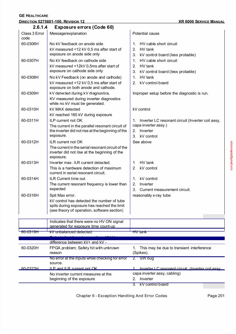
7/24/2019 GE XR6000 X-Ray - Service Manual
http://slidepdf.com/reader/full/ge-xr6000-x-ray-service-manual 201/421
Chapter 6 - Exception Handling And Error Codes Page 201
GE HEALTHCARE
DIRECTION 5275601-100, REVISION 12 XR 6000 SERVICE MANUAL
2.6.1.4 Exposure errors (Code 60)Class 3 Error
code
Message/explanation Potential cause
60-0306H No kV feedback on anode side
kV measured <12 kV 0,5 ms after start of
exposure on anode side only
1. HV cable short circuit
2. HV tank
3. kV control board (less probable)
60-0307H No kV feedback on cathode side
kV measured <12kV 0,5ms after start of
exposure on cathode side only
1. HV cable short circuit
2. HV tank
3. kV control board (less probable)
60-0308H No kV Feedback (on anode and cathode)
kV measured <12 kV 0,5 ms after start of
exposure on both anode and cathode.
1. HV tank
2. kV control board
60-0309H kV detected during kV diagnostics.
KV measured during inverter diagnostics
while no kV must be generated.
Improper setup before the diagnostic is run.
60-0310H kV MAX detected
kV reached 160 kV during exposure
kV control
60-0311H ILP current not OK.
The current in the parallel resonant circuit of
the inverter did not rise at the beginning of the
exposure.
1. Inverter LC resonant circuit (Inverter coil assy,
capa inverter assy.)
2. Inverter
3. kV control
60-0312H ILR current not OK
The current in the serial resonant circuit of the
inverter did not rise at the beginning of the
exposure.
See above
60-0313H Inverter max. ILR current detected.
This is a hardware detection of maximum
current in serial resonant circuit.
1 HV tank
2 kV control
60-0314H ILR Current time out.
The current resonant frequency is lower than
expected
1. kV control
2. Inverter
3. Current measurement circuit.
60-0316H Spit Max error.
kV control has detected the number of tube
spits during exposure has reached the limit
(see theory of operation, software section)
reasonably x-ray tube
60-0318H kV did not reach 75% after 20 ms.
Indicates that there were no HV ON signal
generated for exposure time count-up
1. kV control
60-0319H kV unbalanced detected.
Detects that there is more than 12 kV
difference between kV+ and kV -
HV tank
60-0320H FPGA problem; Safety hit with unknown
reason
No error at the inputs while checking for error
source.
1. This may be due to transient interference
(Spikes).
2. SW bug
60-0323H ILP and ILR current not OK
No inverter current measures at the
beginning of the exposure
1. Inverter LC resonant circuit. (Inverter coil assy,
capa inverter assy, cabling)
2. Inverter
3. kV control board
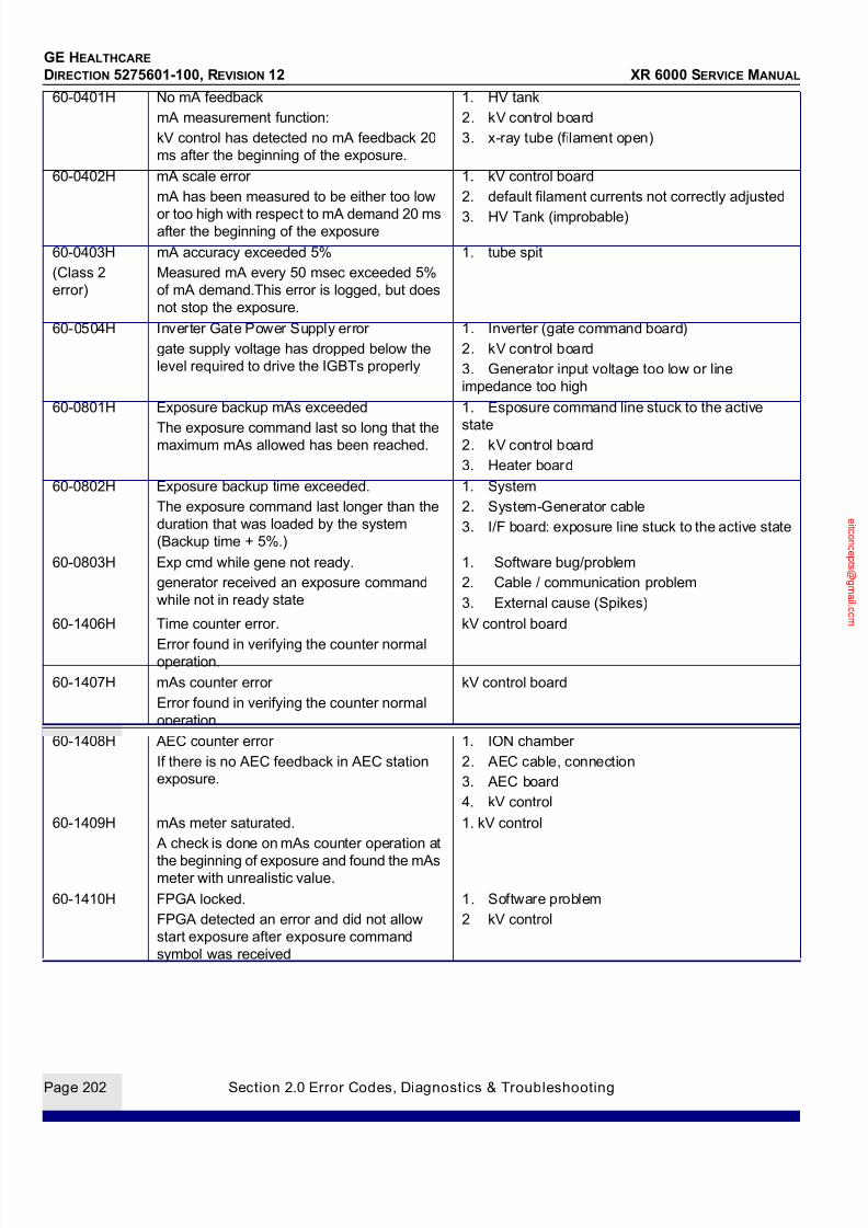
7/24/2019 GE XR6000 X-Ray - Service Manual
http://slidepdf.com/reader/full/ge-xr6000-x-ray-service-manual 202/421
GE HEALTHCARE
DIRECTION 5275601-100, REVISION 12 XR 6000 SERVICE MANUAL
Page 202 Section 2.0 Error Codes, Diagnostics & Troubleshooting
60-0401H No mA feedback
mA measurement function:
kV control has detected no mA feedback 20
ms after the beginning of the exposure.
1. HV tank
2. kV control board
3. x-ray tube (filament open)
60-0402H mA scale error
mA has been measured to be either too low
or too high with respect to mA demand 20 msafter the beginning of the exposure
1. kV control board
2. default filament currents not correctly adjusted
3. HV Tank (improbable)
60-0403H
(Class 2
error)
mA accuracy exceeded 5%
Measured mA every 50 msec exceeded 5%
of mA demand.This error is logged, but does
not stop the exposure.
1. tube spit
60-0504H Inverter Gate Power Supply error
gate supply voltage has dropped below the
level required to drive the IGBTs properly
1. Inverter (gate command board)
2. kV control board
3. Generator input voltage too low or line
impedance too high
60-0801H Exposure backup mAs exceeded
The exposure command last so long that themaximum mAs allowed has been reached.
1. Esposure command line stuck to the active
state2. kV control board
3. Heater board
60-0802H Exposure backup time exceeded.
The exposure command last longer than the
duration that was loaded by the system
(Backup time + 5%.)
1. System
2. System-Generator cable
3. I/F board: exposure line stuck to the active state
60-0803H Exp cmd while gene not ready.
generator received an exposure command
while not in ready state
1. Software bug/problem
2. Cable / communication problem
3. External cause (Spikes)
60-1406H Time counter error.
Error found in verifying the counter normaloperation.
kV control board
60-1407H mAs counter error
Error found in verifying the counter normal
operation.
kV control board
60-1408H AEC counter error
If there is no AEC feedback in AEC station
exposure.
1. ION chamber
2. AEC cable, connection
3. AEC board
4. kV control
60-1409H mAs meter saturated.
A check is done on mAs counter operation at
the beginning of exposure and found the mAsmeter with unrealistic value.
1. kV control
60-1410H FPGA locked.
FPGA detected an error and did not allow
start exposure after exposure command
symbol was received
1. Software problem
2 kV control
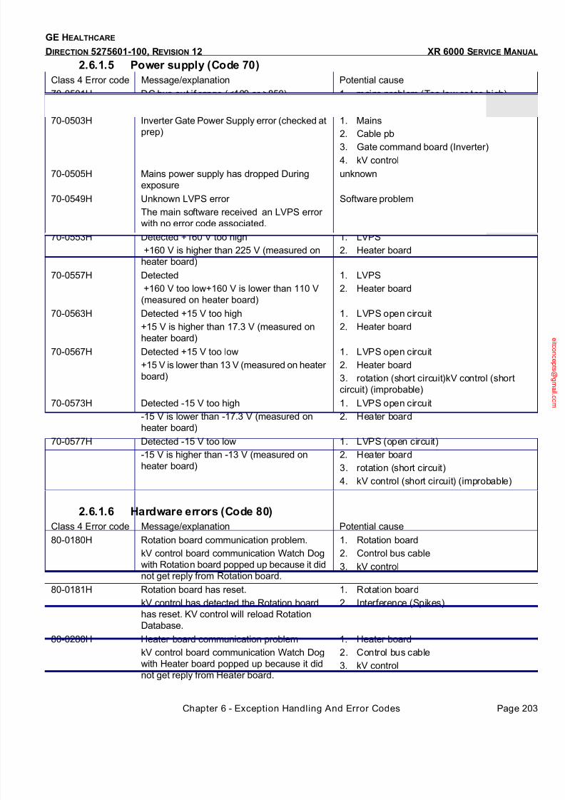
7/24/2019 GE XR6000 X-Ray - Service Manual
http://slidepdf.com/reader/full/ge-xr6000-x-ray-service-manual 203/421
Chapter 6 - Exception Handling And Error Codes Page 203
GE HEALTHCARE
DIRECTION 5275601-100, REVISION 12 XR 6000 SERVICE MANUAL
2.6.1.5 Power supply (Code 70)
2.6.1.6 Hardware errors (Code 80)
Class 4 Error code Message/explanation Potential cause
70-0501H DC bus out if range (<400 or >850) 1. mains problem (Too low or too high)
2. One phase missing at Generator input
70-0503H Inverter Gate Power Supply error (checked at
prep)
1. Mains
2. Cable pb
3. Gate command board (Inverter)
4. kV control
70-0505H Mains power supply has dropped During
exposure
unknown
70-0549H Unknown LVPS error
The main software received an LVPS error
with no error code associated.
Software problem
70-0553H Detected +160 V too high
+160 V is higher than 225 V (measured on
heater board)
1. LVPS
2. Heater board
70-0557H Detected +160 V too low+160 V is lower than 110 V
(measured on heater board)
1. LVPS2. Heater board
70-0563H Detected +15 V too high
+15 V is higher than 17.3 V (measured on
heater board)
1. LVPS open circuit
2. Heater board
70-0567H Detected +15 V too low
+15 V is lower than 13 V (measured on heater
board)
1. LVPS open circuit
2. Heater board
3. rotation (short circuit)kV control (short
circuit) (improbable)
70-0573H Detected -15 V too high
-15 V is lower than -17.3 V (measured onheater board)
1. LVPS open circuit
2. Heater board
70-0577H Detected -15 V too low
-15 V is higher than -13 V (measured on
heater board)
1. LVPS (open circuit)
2. Heater board
3. rotation (short circuit)
4. kV control (short circuit) (improbable)
Class 4 Error code Message/explanation Potential cause
80-0180H Rotation board communication problem.
kV control board communication Watch Dog
with Rotation board popped up because it did
not get reply from Rotation board.
1. Rotation board
2. Control bus cable
3. kV control
80-0181H Rotation board has reset.
kV control has detected the Rotation board
has reset. KV control will reload Rotation
Database.
1. Rotation board
2. Interference (Spikes)
80-0280H Heater board communication problem
kV control board communication Watch Dog
with Heater board popped up because it did
not get reply from Heater board.
1. Heater board
2. Control bus cable
3. kV control
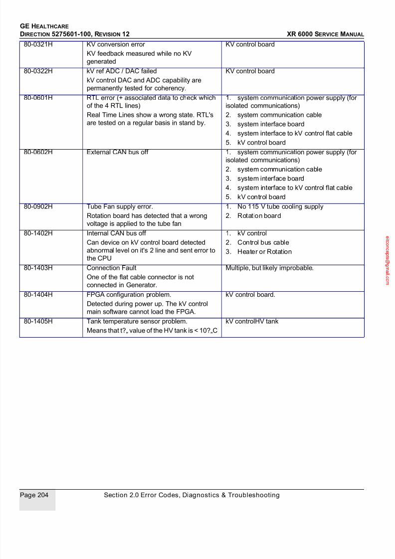
7/24/2019 GE XR6000 X-Ray - Service Manual
http://slidepdf.com/reader/full/ge-xr6000-x-ray-service-manual 204/421
GE HEALTHCARE
DIRECTION 5275601-100, REVISION 12 XR 6000 SERVICE MANUAL
Page 204 Section 2.0 Error Codes, Diagnostics & Troubleshooting
80-0321H KV conversion error
KV feedback measured while no KV
generated
KV control board
80-0322H kV ref ADC / DAC failed
kV control DAC and ADC capability are
permanently tested for coherency.
KV control board
80-0601H RTL error (+ associated data to check whichof the 4 RTL lines)
Real Time Lines show a wrong state. RTL's
are tested on a regular basis in stand by.
1. system communication power supply (forisolated communications)
2. system communication cable
3. system interface board
4. system interface to kV control flat cable
5. kV control board
80-0602H External CAN bus off 1. system communication power supply (for
isolated communications)
2. system communication cable
3. system interface board
4. system interface to kV control flat cable
5. kV control board
80-0902H Tube Fan supply error.
Rotation board has detected that a wrong
voltage is applied to the tube fan
1. No 115 V tube cooling supply
2. Rotation board
80-1402H Internal CAN bus off
Can device on kV control board detected
abnormal level on it's 2 line and sent error to
the CPU
1. kV control
2. Control bus cable
3. Heater or Rotation
80-1403H Connection Fault
One of the flat cable connector is not
connected in Generator.
Multiple, but likely improbable.
80-1404H FPGA configuration problem.Detected during power up. The kV control
main software cannot load the FPGA.
kV control board.
80-1405H Tank temperature sensor problem.
Means that t?„ value of the HV tank is < 10?„C
kV controlHV tank
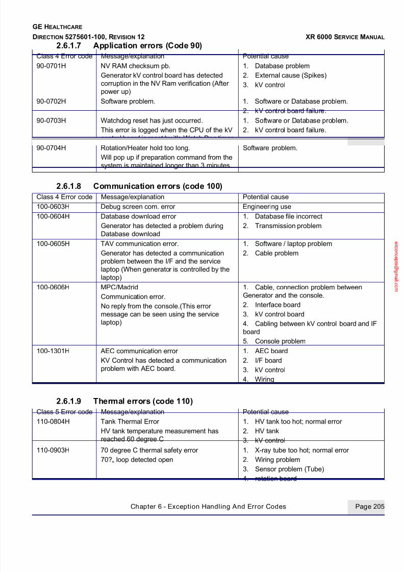
7/24/2019 GE XR6000 X-Ray - Service Manual
http://slidepdf.com/reader/full/ge-xr6000-x-ray-service-manual 205/421
Chapter 6 - Exception Handling And Error Codes Page 205
GE HEALTHCARE
DIRECTION 5275601-100, REVISION 12 XR 6000 SERVICE MANUAL
2.6.1.7 Application errors (Code 90)
2.6.1.8 Communication errors (code 100)
2.6.1.9 Thermal errors (code 110)
Class 4 Error code Message/explanation Potential cause
90-0701H NV RAM checksum pb.
Generator kV control board has detected
corruption in the NV Ram verification (After
power up)
1. Database problem
2. External cause (Spikes)
3. kV control
90-0702H Software problem. 1. Software or Database problem.2. kV control board failure.
90-0703H Watchdog reset has just occurred.
This error is logged when the CPU of the kV
control board is reset by it's Watch Dog timer.
1. Software or Database problem.
2. kV control board failure.
90-0704H Rotation/Heater hold too long.
Will pop up if preparation command from the
system is maintained longer than 3 minutes.
Software problem.
Class 4 Error code Message/explanation Potential cause100-0603H Debug screen com. error Engineering use
100-0604H Database download error
Generator has detected a problem during
Database download
1. Database file incorrect
2. Transmission problem
100-0605H TAV communication error.
Generator has detected a communication
problem between the I/F and the service
laptop (When generator is controlled by the
laptop)
1. Software / laptop problem
2. Cable problem
100-0606H MPC/Madrid
Communication error.
No reply from the console.(This error
message can be seen using the service
laptop)
1. Cable, connection problem between
Generator and the console.
2. Interface board
3. kV control board
4. Cabling between kV control board and IF
board
5. Console problem
100-1301H AEC communication error
KV Control has detected a communication
problem with AEC board.
1. AEC board
2. I/F board
3. kV control
4. Wiring
Class 5 Error code Message/explanation Potential cause
110-0804H Tank Thermal Error
HV tank temperature measurement has
reached 60 degree C
1. HV tank too hot; normal error
2. HV tank
3. kV control
110-0903H 70 degree C thermal safety error
70?„ loop detected open
1. X-ray tube too hot; normal error
2. Wiring problem
3. Sensor problem (Tube)
4. rotation board
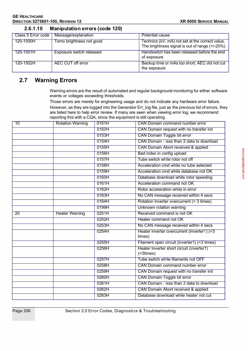
7/24/2019 GE XR6000 X-Ray - Service Manual
http://slidepdf.com/reader/full/ge-xr6000-x-ray-service-manual 206/421
GE HEALTHCARE
DIRECTION 5275601-100, REVISION 12 XR 6000 SERVICE MANUAL
Page 206 Section 2.0 Error Codes, Diagnostics & Troubleshooting
2.6.1.10 Manipulation errors (code 120)
2.7 Warning Errors
Warning errors are the result of automated and regular background monitoring for either software
events or voltages exceeding thresholds.
Those errors are merely for engineering usage and do not indicate any hardware error failure.
However, as they are logged into the Generator Err_log file, just as the previous list of errors, they
are listed here to help error review. If many are seen when viewing error log, we recommend
reporting this with a CQA, since the equipment is still operating.
Class 5 Error code Message/explanation Potential cause
120-1500H Tomo brightness not good Technics (kV, mA) not set at the correct value.
The brightness signal is out of range (+/-20%)
120-1501H Exposure switch released Handswitch has been released before the end
of exposure
120-1502H AEC CUT off error Backup time or mAs too short; AEC did not cut
the exposure
10 Rotation Warning 0151H CAN Domain command number error0152H CAN Domain request with no transfer init
0153H CAN Domain Toggle bit error
0154H CAN Domain : less than 2 data to download
0155H CAN Domain Abort received & applied
0156H Bad index in config upload
0157H Tube switch while rotor not off
0158H Acceleration cmd while no tube selected
0159H Acceleration cmd while database not OK
0160H Database download while rotor speeding
0161H Acceleration command not OK0162H Rotor acceleration while in error
0163H No CAN message received within 4 secs
0164H Rotation Inverter overcurrent (< 3 times)
0199H Unknown rotation warning
20 Heater Warning 0251H Received command is not OK
0252H Heater command not OK
0253H No CAN message received within 4 secs
0254H Heater inverter overcurrent (inverter1) (<3
times)
0255H Filament open circuit (inverter1) (<3 times)
0256H Heater Inverter short circuit (inverter1)
(<3times)
0257H Tube switch while filaments not OFF
0258H CAN Domain command number error
0259H CAN Domain request with no transfer init
0260H CAN Domain Toggle bit error
0261H CAN Domain : less than 2 data to download
0262H CAN Domain Abort received & applied
0263H Database download while heater not cut

7/24/2019 GE XR6000 X-Ray - Service Manual
http://slidepdf.com/reader/full/ge-xr6000-x-ray-service-manual 207/421
Chapter 6 - Exception Handling And Error Codes Page 207
GE HEALTHCARE
DIRECTION 5275601-100, REVISION 12 XR 6000 SERVICE MANUAL
2.8 Other Failures
0299H Unknown heater warning
25 Low Voltage Power
Supply Warnings
0550H No more warn +160V too low or too high
0555H Detected +160V too low
0560H No more warn +15V too low or too high
0561H Detected +15V too high
0565H Detected +15V too low
0570H No more warn -15V too low or too high
0571H Detected -15V too strong
0575H Detected -15V too weak
0599H Unknown LVPS warning
27 Application
warnings
1401H Saved RAM power supply limit reached
This message is the result of a computation
that is made by the software based on the Date
for a period of approximately 7 years
Error code Message/explanation Potential cause
System GENERATOR does not reply to the system 1. No power on Generator
2. EMC filter
3. AC/DC- Diode bridge
4. Cable between AC/DC and LVPS
5. LVPS down
6. CAN cable problem
7. kV control
8. CT interface
9. Rotation board10. Heater board
11. Inverter in short circuit
12. Generator to system cable
3 phases CB1 breaker trips in PDU 1. Short circuit on Generator :
IGBT in short circuit
ACDC or bridge rectifier in short circuit
EMC filter in short circuit
Software or Data base corrupt 1. After software download:
-Incorrect or uncompleted download
-Checksum problem
Error
code
Message /
explanation
Potential cause Recommended action Troubleshooting guide
Console CONSOLE boot
up error
Console power supply is not
correct
Locate the Switch Power DSP1 on the back of
PDU, then adjust VR1 to make 5V terminal out put
5.50.05V.
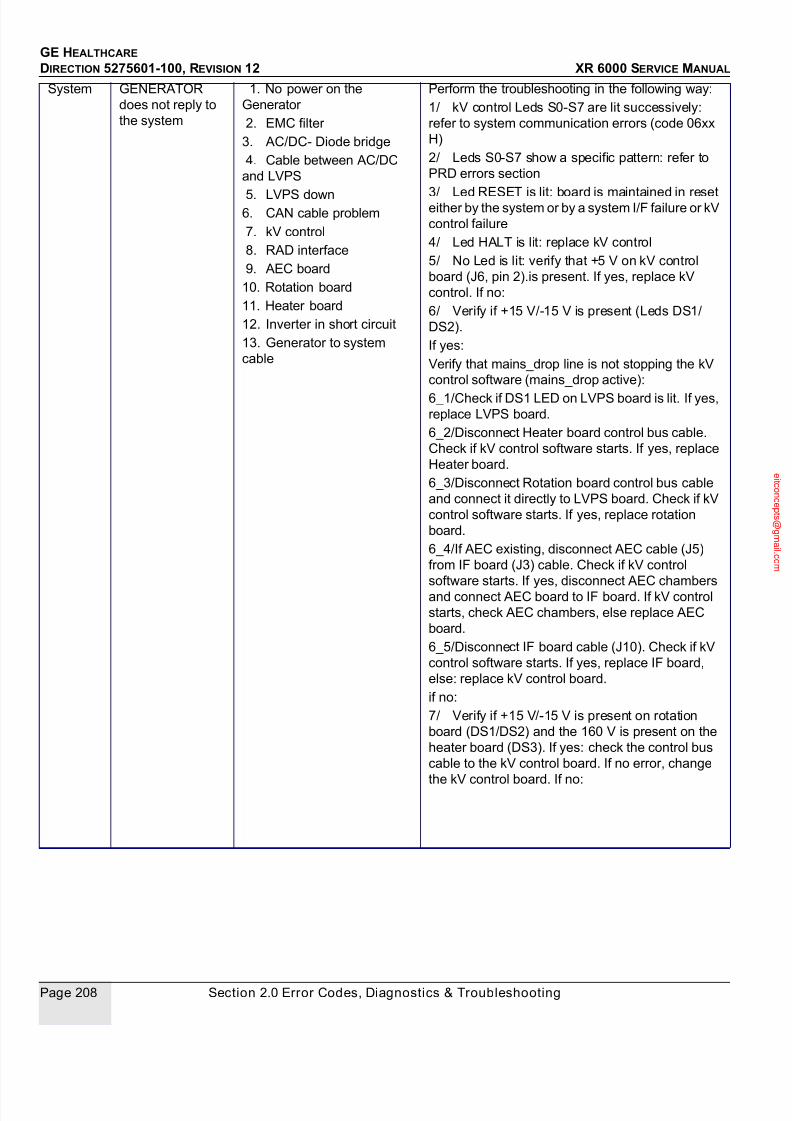
7/24/2019 GE XR6000 X-Ray - Service Manual
http://slidepdf.com/reader/full/ge-xr6000-x-ray-service-manual 208/421
GE HEALTHCARE
DIRECTION 5275601-100, REVISION 12 XR 6000 SERVICE MANUAL
Page 208 Section 2.0 Error Codes, Diagnostics & Troubleshooting
System GENERATOR
does not reply to
the system
1. No power on the
Generator
2. EMC filter
3. AC/DC- Diode bridge
4. Cable between AC/DC
and LVPS
5. LVPS down6. CAN cable problem
7. kV control
8. RAD interface
9. AEC board
10. Rotation board
11. Heater board
12. Inverter in short circuit
13. Generator to system
cable
Perform the troubleshooting in the following way:
1/ kV control Leds S0-S7 are lit successively:
refer to system communication errors (code 06xx
H)
2/ Leds S0-S7 show a specific pattern: refer to
PRD errors section
3/ Led RESET is lit: board is maintained in reseteither by the system or by a system I/F failure or kV
control failure
4/ Led HALT is lit: replace kV control
5/ No Led is lit: verify that +5 V on kV control
board (J6, pin 2).is present. If yes, replace kV
control. If no:
6/ Verify if +15 V/-15 V is present (Leds DS1/
DS2).
If yes:
Verify that mains_drop line is not stopping the kV
control software (mains_drop active):
6_1/Check if DS1 LED on LVPS board is lit. If yes,
replace LVPS board.
6_2/Disconnect Heater board control bus cable.
Check if kV control software starts. If yes, replace
Heater board.
6_3/Disconnect Rotation board control bus cable
and connect it directly to LVPS board. Check if kV
control software starts. If yes, replace rotation
board.
6_4/If AEC existing, disconnect AEC cable (J5)
from IF board (J3) cable. Check if kV control
software starts. If yes, disconnect AEC chambers
and connect AEC board to IF board. If kV control
starts, check AEC chambers, else replace AEC
board.
6_5/Disconnect IF board cable (J10). Check if kV
control software starts. If yes, replace IF board,
else: replace kV control board.
if no:
7/ Verify if +15 V/-15 V is present on rotation
board (DS1/DS2) and the 160 V is present on the
heater board (DS3). If yes: check the control bus
cable to the kV control board. If no error, change
the kV control board. If no:

7/24/2019 GE XR6000 X-Ray - Service Manual
http://slidepdf.com/reader/full/ge-xr6000-x-ray-service-manual 209/421
Chapter 6 - Exception Handling And Error Codes Page 209
GE HEALTHCARE
DIRECTION 5275601-100, REVISION 12 XR 6000 SERVICE MANUAL
2.9 Heating Function diagnostics
Purpose: The purpose of this test is to drive the heater inverter(s) on both filaments and all the tubes
connected to the Generator in order to identify a faulty heater FRU or a wrong connection between
heater board, HV Tank and tube(s).
Pre-requisites: • kV control board alive and running: S0-S7 Leds are lit successively or a combination of them
blink• heater board alive and running: DS1 and DS2 Leds are lit successively
• heater DC supply present: DS3 Led is lit
Test type: No manual interaction
Sequence: Select the tube to run the test on, start the diagnostic.
The following sequence runs on the small focus and then on the large focus:
• 5 seconds preheat
• 0,4 s boost
• 5 s heat (focal spot max current - 1Amp)
There is 10 s stop time between each focal spot run.
During the test, the heater safeties are checked the same way than in application mode.
GENERATOR
does not reply to
the
system(Cond't)
8/ Verify if the LVPS DC input is right. If no, check
AC/DC fuse and input line
If yes:
9/ disconnect all output cables from the LVPS
board. Verify the +15 V/-15 V/160 V output. If right:
reconnect each board successively to find the one
stucking the 15V to ground. If wrong, replace LVPSboard
3 phases CB1
breaker trips in
PDU
1. Short circuit on
Generator:
- IGBT in short circuit
- ACDC or bridge rectifier
in short circuit
- EMC filter in short circuit
1/ Disconnect DC bus cables between AC/DC
and inverter (on AC/DC side)
2/ Check if these cables are in short circuit. If yes,
replace inverter
if no,
3/ Remove ACDC board
4/ Check between outputs pins then between
inputs of ACDC board. If short circuit, replace AC/
DC FRU
if no:
5/ Check bridge rectifier, between outputs, if yes,
replace ACDC FRU (including rectifier bridge)
if no:
6/ Check bridge rectifier, between inputs, if yes,
replace ACDC FRU (including rectifier bridge)
if no:
7/ Disconnect AC line input from EMC board.
Check EMC for short circuit between phases. If
short circuit, replace EMC board.
Software or Data
base corrupt
1. After software download:
- Incorrect or uncompleted
download- Checksum problem
Retry download
Console display
malfunction
Console power does not
reach the specification
PDU DPS1:V1 output should be +5V. Adjust the
potentiometer if needed.

7/24/2019 GE XR6000 X-Ray - Service Manual
http://slidepdf.com/reader/full/ge-xr6000-x-ray-service-manual 210/421
GE HEALTHCARE
DIRECTION 5275601-100, REVISION 12 XR 6000 SERVICE MANUAL
Page 210 Section 2.0 Error Codes, Diagnostics & Troubleshooting
Error codes reporting:
Refer to the troubleshooting table.
2.10 Rotation Function diagnostics
Purpose: The purpose of this test is to drive the rotation inverter(s) in high speed mode (for application
supporting high speed mode) and low speed mode on all the tubes connected to the Generator inorder to identify a faulty rotation FRU or a faulty dephasing capacitors FRU or a wrong connection
between rotation board and tube.
Pre-requisites: • kV control board alive and running: S0-S7 Leds are lit successively or a combination of them
blink
• rotation board alive and running: DS5 Led blinking
• rotation DC supply present: DS7 neon is lit
• cabling between rotation board and tube checked
Test type: No manual interaction, no loop on
Sequence: Select the tube to run the test on, start the diagnostic.
The following sequence runs in low speed mode and then in high speed mode (if high speed mode
allowed):
• acceleration (time depends on tube type)
• 2 s run
• brake (time depends on tube type)
There is 2 s stop time between each speed mode.
During the test, the rotation safeties are checked the same way than in application mode.
Error codes reporting:
For the other error codes, refer to the troubleshooting table.
2.11 Inverter in Short Circuit Function diagnostics
Purpose: The purpose of this test is to verify that the HV power inverter is working properly. The inverter is
commanded at a fixed frequency and is loaded with a short circuit. Verification is made that the
inverter currents are correctly set. At the same time verification is made that no High voltage ismeasured. This test is performed without connecting the HV Tank to the inverter so that no Xray is
generated. Anode rotation and filament drive are not activated during this test.
Pre-requisites: • Generator input line in an acceptable range (380 V-10% to 480 V+10% for 3-phase AC input)
• kV control board alive and running: S0-S7 Leds are lit successively or a combination of them
blink
• inverter gate_cmd board DC supply present: DS300 neon is lit
• inverter dual snubber board DC supply present: DS1 neon is lit
• Inverter gate command diagnostic passed without failure
Test type: Manual operation is required.
Error code Associated data Conclusion
0103H
0104H
0105H
0106H
Associated data points only to high speed
mode
Power-off. Check if rotation board K2 relay is
short circuiting the rotor capacitors. If yes
replace the rotation board. If no replace the
rotation capacitors
0103H
0104H
0105H
0106H
Associated data points to both high speed
and low speed mode
Replace the rotation board
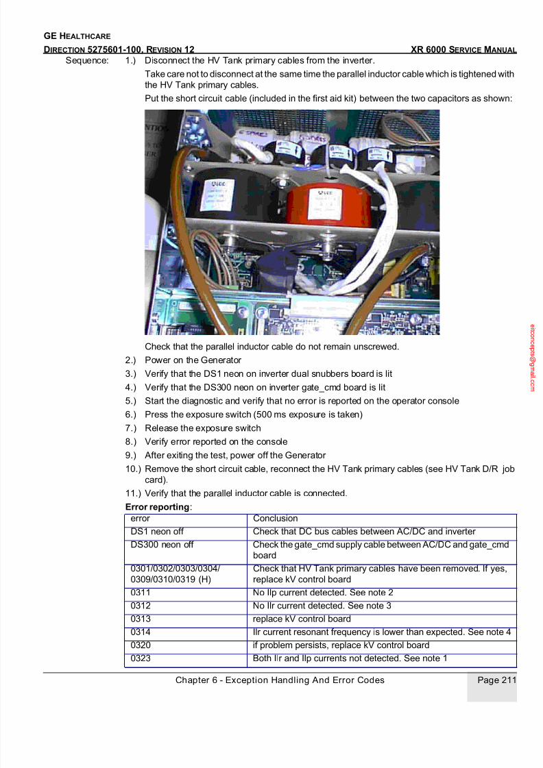
7/24/2019 GE XR6000 X-Ray - Service Manual
http://slidepdf.com/reader/full/ge-xr6000-x-ray-service-manual 211/421
Chapter 6 - Exception Handling And Error Codes Page 211
GE HEALTHCARE
DIRECTION 5275601-100, REVISION 12 XR 6000 SERVICE MANUAL
Sequence: 1.) Disconnect the HV Tank primary cables from the inverter.
Take care not to disconnect at the same time the parallel inductor cable which is tightened with
the HV Tank primary cables.
Put the short circuit cable (included in the first aid kit) between the two capacitors as shown:
Check that the parallel inductor cable do not remain unscrewed.
2.) Power on the Generator
3.) Verify that the DS1 neon on inverter dual snubbers board is lit
4.) Verify that the DS300 neon on inverter gate_cmd board is lit
5.) Start the diagnostic and verify that no error is reported on the operator console6.) Press the exposure switch (500 ms exposure is taken)
7.) Release the exposure switch
8.) Verify error reported on the console
9.) After exiting the test, power off the Generator
10.) Remove the short circuit cable, reconnect the HV Tank primary cables (see HV Tank D/R job
card).
11.) Verify that the parallel inductor cable is connected.
Error reporting:
error Conclusion
DS1 neon off Check that DC bus cables between AC/DC and inverter
DS300 neon off Check the gate_cmd supply cable between AC/DC and gate_cmd
board
0301/0302/0303/0304/
0309/0310/0319 (H)
Check that HV Tank primary cables have been removed. If yes,
replace kV control board
0311 No Ilp current detected. See note 2
0312 No Ilr current detected. See note 3
0313 replace kV control board
0314 Ilr current resonant frequency is lower than expected. See note 4
0320 if problem persists, replace kV control board
0323 Both Ilr and Ilp currents not detected. See note 1

7/24/2019 GE XR6000 X-Ray - Service Manual
http://slidepdf.com/reader/full/ge-xr6000-x-ray-service-manual 212/421
GE HEALTHCARE
DIRECTION 5275601-100, REVISION 12 XR 6000 SERVICE MANUAL
Page 212 Section 2.0 Error Codes, Diagnostics & Troubleshooting
Note 1: Ilp and Ilr currents not detected
1.) Check the -15 V (Led DS1) on kV control board (see central listing). If it is not lit, refer to "other
failures" section. Else:
2.) Power off the Generator. Wait until all neons are off.
3.) Check that the currents transformers (capacitor set) to gate_cmd board cable is correctly
connected. If yes:
4.) Check that the inverter inductors are correctly connected. If yes:
5.) Check that the gate_cmd to HV Tank cable and HV Tank to kV control cables are correctly
connected. If yes, replace the inverter
6.) Reconnect all the cables
Note 2: Ilp current not detected
1.) Power off the Generator. Wait until all neons are off.
2.) Check that the parallel inductor is correctly connected. If yes:
3.) Check that the parallel inductor impedance is 0 Ohms. If no: replace inverter. If yes:
4.) Check that inverter capacitors (capacitors set) are not broken. If yes, replace the capacitor set.
Else:
5.) Disconnect the currents transformers to gate_cmd board cable. Check that the parallel current
transformer impedance is 0. If no: replace the capacitor set. Else:
6.) Check that the gate_cmd to HV Tank cable and HV Tank to kV control cables are correctly
connected. If yes:
7.) Disconnect the HV Tank to kV control cable. Check that the impedance between pin 20 andpin 21 of J2 of HV Tank is 3,3 Ohms. If no replace the inverter. If yes replace kV control board.
8.) Reconnect all the cables.
Note 3: Ilr current not detected
1.) Power off the Generator. Wait until all neons are off
2.) Check that the inductors are correctly connected. If yes:
3.) Disconnect the currents transformers to gate_cmd board cable. Check that the serial current
transformer impedance is 0. If no: change capacitor set. Else:
4.) Check that inverter capacitors (capacitors set) are not broken. If yes, replace the capacitor set.
Else:
5.) Check that the gate_cmd to HV Tank cable and HV Tank to kV control cables are correctly
connected. If yes:
6.) Disconnect the HV Tank to kV control cable. Check that the impedance between pin 20 and
pin 21 of J2 of HV Tank is 5 Ohms. If no replace iverter. If yes replace kV control board.
7.) Reconnect all the cables
Note 4: Ilr current resonant frequency is lower than expected
1.) Power off the Generator. Wait until all neons are off.
2.) Check that the inductors are correctly connected. If yes:
3.) Check that the inverter capacitors (capacitors set) are not broken. If yes: replace the apacitor
set. Else:
4.) Disconnect the currents transformers to gate_cmd board cable. Check that the parallel current
0501 kV control or inverter can be faulty
0503 kV control or inverter can be faulty
0504 kV control or inverter can be faulty
0505 Isolation fault between inverter components and ground. Check
inverter inductors. If no faulty component, kV control or inverter
can be faulty

7/24/2019 GE XR6000 X-Ray - Service Manual
http://slidepdf.com/reader/full/ge-xr6000-x-ray-service-manual 213/421
Chapter 6 - Exception Handling And Error Codes Page 213
GE HEALTHCARE
DIRECTION 5275601-100, REVISION 12 XR 6000 SERVICE MANUAL
transformer impedance is 0. If no: change the capacitor set. Else: replace kV control board.
5.) Reconnect all the cables
2.12 AEC diagnostics
Purpose: The purpose of this test is to drive the AEC function in order to identify a faulty AEC, IF or kV control
board FRU or the wrong connection between the AEC board and ion chambers.Pre-requisites: • application mode without AEC mode is running properly
• kV Control board alive and running: S0-S7 LEDs are lit successively or a combination of them
blink
• cabling between IF board, AEC board and ionization chambers checked.
Test type: Automated, with the use of Service Laptop
Sequence: Select AEC function in menu 1 on Service Laptop.
Press V to run the test.
AEC function is verified through a series of 7 tests as follows:
• AEC return measurement test:
A voltage reference is switched to one input of the AEC select multiplex.
Nominal value of return voltage = 5.24 VTest 1 is OK if: 4 V < measured value < 6 V
This test is also performed at lower frequency count up:
Test 2 is OK if: 4 V < measured value < 6 V.
• Switching Gain test (x10):
A voltage reference is switched to one input of the AEC select multiplex and count up gain is
applied.
Nominal value of return volatge = 4.76 V
Test 3 is OK if: 4 V < measured value < 6 V.
• AEC ion chamber HV power supply test:
A portion of HV power supply is switched to one input of the AEC select multiplex:
- No cell selected, Test 4 is OK if return voltage measurement is 0 V.
- Select respectively one of the three cells, left, right, middle.
Test 5, 6, 7 are OK if: 1 V < measured value < 3 V.
Error codes reporting:
(*) except for AEC board with serial number: 2184569-X: the resulting error code must be 0001111
(test is OK on this board the HV power supply test is not performed).
For the other error codes, refer to the troubleshooting table.
2.13 No Load HV diagnostics
Purpose: The purpose of this test is to verify that the HV power inverter and HV tank are working properly.
The exposure is taken as in application mode except that no filament drive nor anode rotation is
running. Verification is made that the inverter currents are correctly set and that kV regulation is
operating properly. As no filament drive is applied, no XRays are generated.
Error Code Associated Data Conclusion
1111111 (*) None Test OK
Any combination None Test KO = test failed; replace AEC board
0001000 None Communication error:
- Replace AEC board
- If same problem, apart from a DOA board, suspect
IF board then KV Control board.

7/24/2019 GE XR6000 X-Ray - Service Manual
http://slidepdf.com/reader/full/ge-xr6000-x-ray-service-manual 214/421
GE HEALTHCARE
DIRECTION 5275601-100, REVISION 12 XR 6000 SERVICE MANUAL
Page 214 Section 2.0 Error Codes, Diagnostics & Troubleshooting
This test also allow to separate Generator from HV cable or x-ray tube problem by running it with
or without the HV cables plugged on the HV tank.
Pre-requisites: • Generator input line in an acceptable range (380 V -10% to 480 V +10% for 3-phase AC input)
• kV control board alive and running: S0-S7 Leds are lit successively or a combination of them
blink
• inverter gate_cmd board DC supply present: DS300 neon is lit
• inverter dual snubber board DC supply present: DS1 neon is lit• Inverter gate command diagnostic passed without failure
• Inverter in short circuit diagnostic passed without failure
• *) HV Receptacles must be filled with oil if HV cables are removed.
Test type: Manual operation is required.
Sequence: 1.) Power on the Generator
2.) Start the diagnostic and verify:
- error reported on the operator console
- inverter gate_cmd board Leds DS101, DS102, DS201, DS202 are lit: IGBTs gate drive
supply is working properly
3.) Select kV (default = 80 kV) and exposure time (default = 1 sec.).
4.) Press the exposure switch
5.) During the "exposure", verify:
- error reported on the operator console
6.) Release the exposure switch
7.) Power off the Generator
Error reporting:
See Troubleshooting Table.
2.14 Inverter Gate Command diagnostics
Purpose: The purpose of this test is to verify that the HV power inverter drive is working properly. The IGBTsgate drive supply and the IGBTs gate drive is verified. At the same time verification is made that no
inverter currents nor High voltage are measured. This test is performed without DC voltage applied
to the inverter so that no Xray is generated. Anode rotation and filament drive are not activated
during this test.
Pre-requisites: • generator input line in an acceptable range (380V-10% to 480V+10% for 3-phase AC input)
• kV control board alive and running: S0-S7 Leds are lit successively or a combination of them
blink
• inverter gate_cmd board DC supply present: DS300 neon is lit
Test type: Manual operation is required.
Sequence: 1.) Switch the system OFF. Ensure there is no voltage on AC/DC board
2.) FOR XR 6000:
- Remove DC BUS cable going to Inverter (refer to Chapter 8 - - Renewal Parts-3.4 -
Inverter Mid-Power Assembly).
- Remove the EMC cover (refer to Chapter 8 - - Renewal Parts-3.4 - Inverter Mid-Power
Assembly).
- Refer to Central Listing to "GATE COMMAND BOARD" and to "DUAL SNUB BOARD" for
leds location.
3.) Power on the Generator
4.) Verify that the DS1 neon on inverter dual snubbers board is not lit
5.) Start the diagnostic and verify:
- error reported on the operator console

7/24/2019 GE XR6000 X-Ray - Service Manual
http://slidepdf.com/reader/full/ge-xr6000-x-ray-service-manual 215/421
Chapter 6 - Exception Handling And Error Codes Page 215
GE HEALTHCARE
DIRECTION 5275601-100, REVISION 12 XR 6000 SERVICE MANUAL
- inverter gate_cmd board Leds DS101, DS102, DS201, DS202 are lit: IGBTs gate drive
supply is working properly
6.) Press the exposure switch (10 s exposure is taken after a 10 sec. delay)
7.) During the "exposure", verify:
- error reported on the operator console
- inverter gate_cmd board Leds DS100 and DS200 are lit: IGBTs gate drive is working
properly
8.) Release the exposure switch
9.) Power off the Generator
10.) Reconnect the 2 DC bus cables from the AC/DC board (see Central Listing).
Error reporting:Error Conclusion
DS1 neon lit Check that DC bus cables have been removed
DS300 neon off Check the gate_cmd supply cable between AC/DC and gate_cmd
board
0301/0302/0303/0304/
0309/0310/0311/0312/
0313/0314/0319/0323
(H)
Check that DC bus cables have been removed.
If yes, replace kV control board
0320 if problem persists, replace Kv control board
0501 kV control or inverter fault, replace inverter first
0503 kV control or inverter fault, replace inverter first
0504 kV control or inverter fault, replace inverter first
one of DS101/DS102/
DS201/DS202 LEDs off
while no error reported
Replace inverter
DS100 and/or DS200
LEDs off
Check cabling between kV control, HV Tank and gate_cmd board.
If cabling is right, kV control or inverter fault, replace inverter first
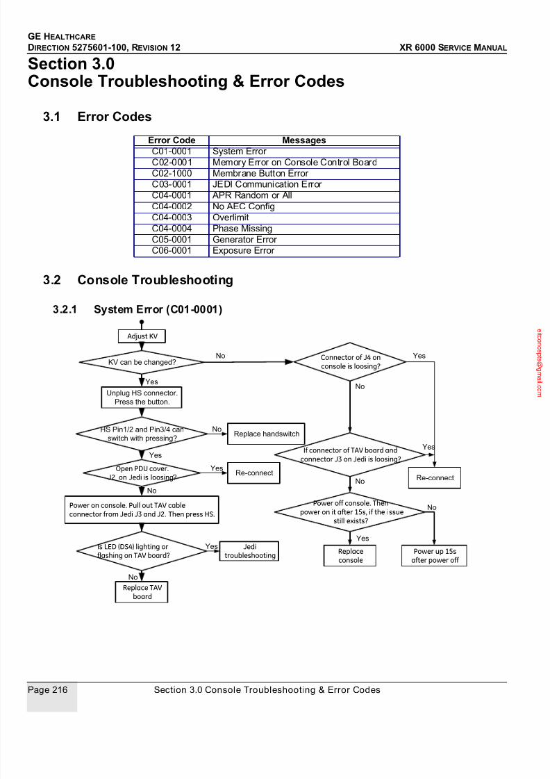
7/24/2019 GE XR6000 X-Ray - Service Manual
http://slidepdf.com/reader/full/ge-xr6000-x-ray-service-manual 216/421
GE HEALTHCARE
DIRECTION 5275601-100, REVISION 12 XR 6000 SERVICE MANUAL
Page 216 Section 3.0 Console Troubleshooting & Error Codes
Section 3.0 Console Troubleshooting & Error Codes
3.1 Error Codes
3.2 Console Troubleshooting
3.2.1 System Error (C01-0001)
Error Code MessagesC01-0001 System Error
C02-0001 Memory Error on Console Control Board
C02-1000 Membrane Button Error
C03-0001 JEDI Communication Error
C04-0001 APR Random or All
C04-0002 No AEC Config
C04-0003 Overlimit
C04-0004 Phase Missing
C05-0001 Generator Error
C06-0001 Exposure Error
Adjust KV
Yes
KV can be changed?
Press the button.
No
HS Pin1/2 and Pin3/4 can
switch with pressing?
Yes
No
Open PDU cover.J2 on Jedi is loosing?
Yes
No
Power on console. Pull out TAV cableconnector from Jedi J3 and J2. Then press HS.
Is LED (DS4) lighting orflashing on TAV board?
Connector of J4 onconsole is loosing?
If connector of TAV board andconnector J3 on Jedi is loosing?
Power off console. Then power on it after 15s, if the issue
still exists?
Yes
No
No
Yes
No
Yes
No
Yes
Replace handswitch
Re-connect
Replace TAVboard
Replaceconsole
Re-connect
Power up 15safter power off
Jeditroubleshooting
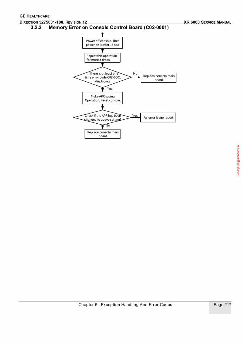
7/24/2019 GE XR6000 X-Ray - Service Manual
http://slidepdf.com/reader/full/ge-xr6000-x-ray-service-manual 217/421
Chapter 6 - Exception Handling And Error Codes Page 217
GE HEALTHCARE
DIRECTION 5275601-100, REVISION 12 XR 6000 SERVICE MANUAL
3.2.2 Memory Error on Console Control Board (C02-0001)
Power off console. Thenpower on it after 15 sec.
Repeat this operation
for more 3 times.
If there is at least onetime error code C02-0001
displaying.
No
Yes
Make APR savingOperation. Reset console.
Check if the APR has been
changed to above setting?
Yes
No
Replace console main
board
As error issue report
Replace console main
board
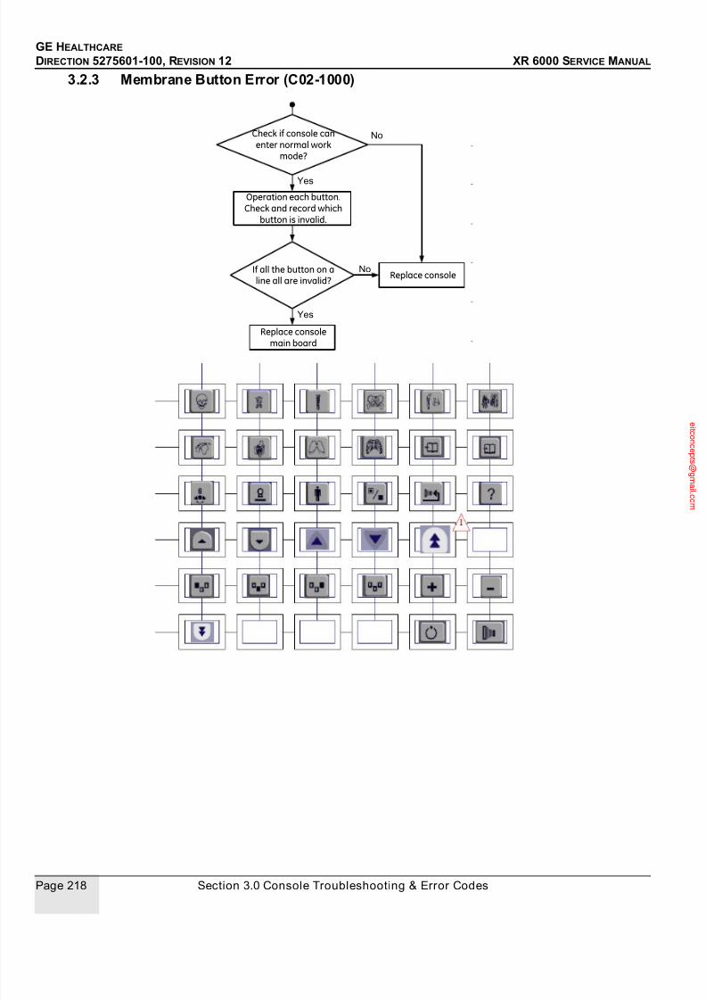
7/24/2019 GE XR6000 X-Ray - Service Manual
http://slidepdf.com/reader/full/ge-xr6000-x-ray-service-manual 218/421
GE HEALTHCARE
DIRECTION 5275601-100, REVISION 12 XR 6000 SERVICE MANUAL
Page 218 Section 3.0 Console Troubleshooting & Error Codes
3.2.3 Membrane Button Error (C02-1000)
Operation each button.Check and record which
button is invalid.
Check if console canenter normal work
mode?
If all the button on aline all are invalid?
Yes
No
Yes
NoReplace console
Replace consolemain board

7/24/2019 GE XR6000 X-Ray - Service Manual
http://slidepdf.com/reader/full/ge-xr6000-x-ray-service-manual 219/421
Chapter 6 - Exception Handling And Error Codes Page 219
GE HEALTHCARE
DIRECTION 5275601-100, REVISION 12 XR 6000 SERVICE MANUAL
3.2.4 JEDI Communication Error (C03-0001)
3.2.5 APR Random or All (C04-0001) APR parameters are invalid, its root cause is perhaps one or more parameters from local database
are over-limit. LCD screen will display zero.
3.2.6 No AEC Config (C04-0002) AEC Operation will be regarded as an error, if there is not AEC configuration.
3.2.7 Overlimit (C04-0003)Value is out of predefined range. Jedi can not accept.
Yes
Check if connector J4of console is loosing?
Power off console, thenpower on it after 15 sec
Check if the errordisappears?
Power off console. OpenPDU cover
Check if the connectorof TAV board and J3 connector
of Jedi is loosing?
Open TAV cover,and power on console. Check if
LED DS1 is light?Check if DS3 is flashing?
Yes
No
No
Yes
No
YesCheck if DS2 is flashing?
No
Yes
No
No
Yes
Replace consoleReplace console
or TAV boardReplace TAVboard
Re-connect
Power up 15safter power off
Jeditroubleshooting
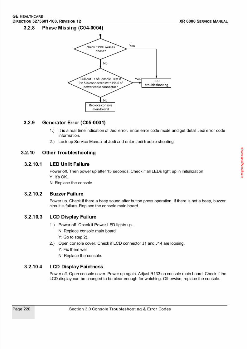
7/24/2019 GE XR6000 X-Ray - Service Manual
http://slidepdf.com/reader/full/ge-xr6000-x-ray-service-manual 220/421
GE HEALTHCARE
DIRECTION 5275601-100, REVISION 12 XR 6000 SERVICE MANUAL
Page 220 Section 3.0 Console Troubleshooting & Error Codes
3.2.8 Phase Missing (C04-0004)
3.2.9 Generator Error (C05-0001)1.) It is a real time indication of Jedi error. Enter error code mode and get detail Jedi error code
information.
2.) Look up Service Manual of Jedi and enter Jedi trouble shooting.
3.2.10 Other Troubleshooting
3.2.10.1 LED Unlit FailurePower off. Then power up after 15 seconds. Check if all LEDs light up in initialization.
Y: It’s OK.
N: Replace the console.
3.2.10.2 Buzzer FailurePower up. Check if there a beep sound after button press operation. If there is not a beep, buzzer
circuit is failure. Replace the console main board.
3.2.10.3 LCD Display Failure
1.) Power off. Check if Power LED lights up.
N: Replace console main board;
Y: Go to step 2).
2.) Open console cover. Check if LCD connector J1 and J14 are loosing.Y: Fix them well;
N: Replace the console.
3.2.10.4 LCD Display FaintnessPower off. Open console cover. Power up again. Adjust R133 on console main board. Check if the
LCD display can be changed to be clear enough for watching. Otherwise, replace the console.
check if PDU missesphase?
Yes
No
No
Pull out J3 of Console. Test ifPin 5 is connected with Pin 6 of
power cable connector?
YesPDU
troubleshooting
Replace consolemain board

7/24/2019 GE XR6000 X-Ray - Service Manual
http://slidepdf.com/reader/full/ge-xr6000-x-ray-service-manual 221/421
Chapter 6 - Exception Handling And Error Codes Page 221
GE HEALTHCARE
DIRECTION 5275601-100, REVISION 12 XR 6000 SERVICE MANUAL
3.2.10.5 Power Un failurePower off. Pull out J3 connector from console. Check if there is 24VDC between Pin1 and Pin2 of
Power cable. This is console 24V supplier from PDU. If it does not exist, check PDU. Otherwise,
replace the console main board.
Section 4.0PDU Troubleshooting
4.1 PDU Troubleshooting
4.1.1 No Console Power
Check TM1 1,2,3 is380VAC and BK is
close
Close BK orhostipital BK
N
Y
Check DSP1 input is110 VAC or not
N Check T1 output is110VAC or not
Y Replace F3 orfilter NF1
Y
Check DSP1 output is24 V or not
Replace DSP1
N
Replace Consoleor Console Cable
YCheck T1 input is380 VAC or not
N
Replace F1
N
Replace T1Y
No Console Power

7/24/2019 GE XR6000 X-Ray - Service Manual
http://slidepdf.com/reader/full/ge-xr6000-x-ray-service-manual 222/421
GE HEALTHCARE
DIRECTION 5275601-100, REVISION 12 XR 6000 SERVICE MANUAL
Page 222 Section 4.0 PDU Troubleshooting
4.1.2 No EM Lock Power or No Collimator Power
No EM lock poweror
No collimator power
Check LED1 is light ornot
Close BK orhostipital BK
N
Check DSP2 input is110 VAC or not
N Check T2 output is110VAC or not
Y
Check DSP2 output is24 V or not
Replace DSP2
N
Replace EM lockor
Replace Collimator
YCheck T2 input is380 VAC or not
N
N
Check CT2 is close ornot
Check K1 is close ornot
N
N
Check TM3 1 vs 7 voltageis 24 VDC or not
Replace Console
Y
Replace F4Y
Replace T2Y
Replace F2Y
Replace CT2Y
Replace K1Y

7/24/2019 GE XR6000 X-Ray - Service Manual
http://slidepdf.com/reader/full/ge-xr6000-x-ray-service-manual 223/421
Chapter 6 - Exception Handling And Error Codes Page 223
GE HEALTHCARE
DIRECTION 5275601-100, REVISION 12 XR 6000 SERVICE MANUAL
4.1.3 No Generator Power
NO Generator
Power
Check TM1 1,2,3 is
380VAC
Check hospitalpower
N
Y
Check CT1 is close ornot
YReplace CT1
N
Check DSP1 output is24 VDC or not
Y
Refer to No Console PowerTroubleshooting Chart
Y
N
Check K1 is close ornot
N
Check TM3 1 vs 7 voltage
is 24 VDC or not
N
Replace Console
N
N
Replace K1
Y
Check CT2 is close ornot
Check T2 is output is
110 VAC or not
Y
Replace K2
Y
Replace F2
Replace CT2N

7/24/2019 GE XR6000 X-Ray - Service Manual
http://slidepdf.com/reader/full/ge-xr6000-x-ray-service-manual 224/421
GE HEALTHCARE
DIRECTION 5275601-100, REVISION 12 XR 6000 SERVICE MANUAL
Page 224 Section 4.0 PDU Troubleshooting
This page is intentionally left blank.
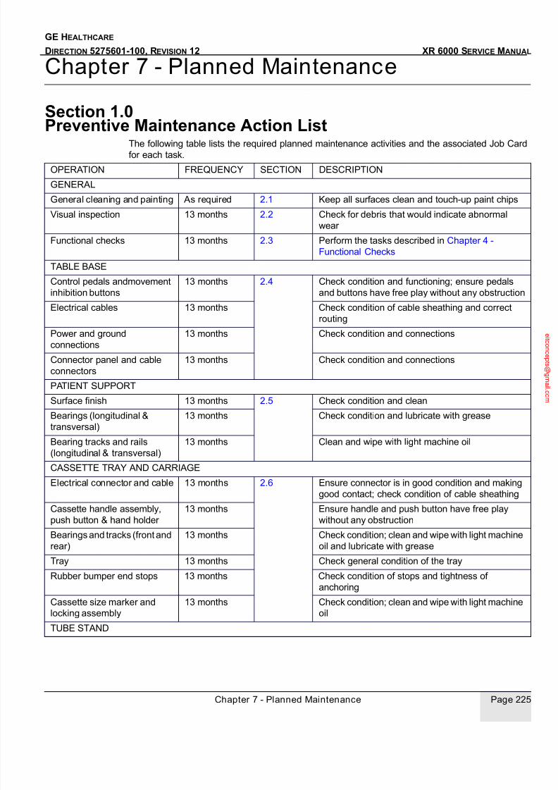
7/24/2019 GE XR6000 X-Ray - Service Manual
http://slidepdf.com/reader/full/ge-xr6000-x-ray-service-manual 225/421
Chapter 7 - Planned Maintenance Page 225
GE HEALTHCARE
DIRECTION 5275601-100, REVISION 12 XR 6000 SERVICE MANUAL
Chapter 7 - Planned Maintenance
Section 1.0 Preventive Maintenance Action List
The following table lists the required planned maintenance activities and the associated Job Card
for each task.
OPERATION FREQUENCY SECTION DESCRIPTION
GENERAL
General cleaning and painting As required 2.1 Keep all surfaces clean and touch-up paint chips
Visual inspection 13 months 2.2 Check for debris that would indicate abnormal
wear
Functional checks 13 months 2.3 Perform the tasks described in Chapter 4 -
Functional Checks
TABLE BASE
Control pedals andmovement
inhibition buttons
13 months 2.4 Check condition and functioning; ensure pedals
and buttons have free play without any obstruction
Electrical cables 13 months Check condition of cable sheathing and correct
routing
Power and ground
connections
13 months Check condition and connections
Connector panel and cable
connectors
13 months Check condition and connections
PATIENT SUPPORT
Surface finish 13 months 2.5 Check condition and clean
Bearings (longitudinal &transversal)
13 months Check condition and lubricate with grease
Bearing tracks and rails
(longitudinal & transversal)
13 months Clean and wipe with light machine oil
CASSETTE TRAY AND CARRIAGE
Electrical connector and cable 13 months 2.6 Ensure connector is in good condition and making
good contact; check condition of cable sheathing
Cassette handle assembly,
push button & hand holder
13 months Ensure handle and push button have free play
without any obstruction
Bearings and tracks (front and
rear)
13 months Check condition; clean and wipe with light machine
oil and lubricate with grease
Tray 13 months Check general condition of the tray
Rubber bumper end stops 13 months Check condition of stops and tightness of
anchoring
Cassette size marker and
locking assembly
13 months Check condition; clean and wipe with light machine
oil
TUBE STAND
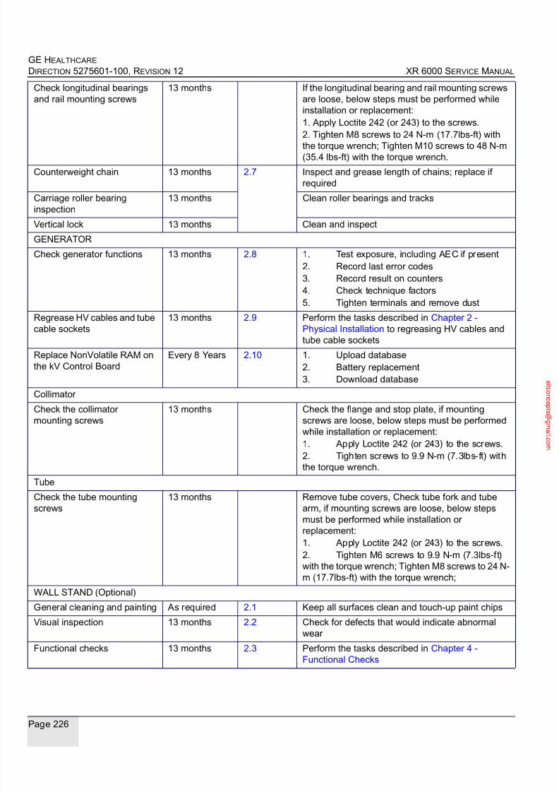
7/24/2019 GE XR6000 X-Ray - Service Manual
http://slidepdf.com/reader/full/ge-xr6000-x-ray-service-manual 226/421
GE HEALTHCARE
DIRECTION 5275601-100, REVISION 12 XR 6000 SERVICE M ANUAL
Page 226
Check longitudinal bearings
and rail mounting screws
13 months If the longitudinal bearing and rail mounting screws
are loose, below steps must be performed while
installation or replacement:
1. Apply Loctite 242 (or 243) to the screws.
2. Tighten M8 screws to 24 N-m (17.7lbs-ft) withthe torque wrench; Tighten M10 screws to 48 N-m
(35.4 lbs-ft) with the torque wrench.
Counterweight chain 13 months 2.7 Inspect and grease length of chains; replace if
required
Carriage roller bearing
inspection
13 months Clean roller bearings and tracks
Vertical lock 13 months Clean and inspect
GENERATOR
Check generator functions 13 months 2.8 1. Test exposure, including AEC if present
2. Record last error codes
3. Record result on counters4. Check technique factors
5. Tighten terminals and remove dust
Regrease HV cables and tube
cable sockets
13 months 2.9 Perform the tasks described in Chapter 2 -
Physical Installation to regreasing HV cables and
tube cable sockets
Replace NonVolatile RAM on
the kV Control Board
Every 8 Years 2.10 1. Upload database
2. Battery replacement
3. Download database
Collimator
Check the collimator
mounting screws
13 months Check the flange and stop plate, if mounting
screws are loose, below steps must be performed
while installation or replacement:
1. Apply Loctite 242 (or 243) to the screws.
2. Tighten screws to 9.9 N-m (7.3lbs-ft) with
the torque wrench.
Tube
Check the tube mounting
screws
13 months Remove tube covers, Check tube fork and tube
arm, if mounting screws are loose, below steps
must be performed while installation or
replacement:
1. Apply Loctite 242 (or 243) to the screws.
2. Tighten M6 screws to 9.9 N-m (7.3lbs-ft)with the torque wrench; Tighten M8 screws to 24 N-
m (17.7lbs-ft) with the torque wrench;
WALL STAND (Optional)
General cleaning and painting As required 2.1 Keep all surfaces clean and touch-up paint chips
Visual inspection 13 months 2.2 Check for defects that would indicate abnormal
wear
Functional checks 13 months 2.3 Perform the tasks described in Chapter 4 -
Functional Checks

7/24/2019 GE XR6000 X-Ray - Service Manual
http://slidepdf.com/reader/full/ge-xr6000-x-ray-service-manual 227/421
Chapter 7 - Planned Maintenance Page 227
GE HEALTHCARE
DIRECTION 5275601-100, REVISION 12 XR 6000 SERVICE MANUAL
Section 2.0
Preventive Maintenance
The following pages list the preventive maintenance detailed activities.
2.1 General Cleaning and Painting
2.1.1 SuppliesCleaning liquids and compounds.
Touch-up paint.
2.1.2 ToolsNone.
2.1.3 Safety PrecautionsRemove power from the system before beginning work.
Check that the power is off.
2.1.4 prerequisites
None.
2.1.5 Personnel1 person.
2.1.6 Time15 minutes.
2.1.7 Procedure
1.) Remove power from the system.
2.) Carefully clean all surfaces of the system. Note any paint damage as you clean the system.
3.) Apply touch-up paint to any paint-damage areas.
4.) Reapply power to the system.
2.2 Visual Inspection
2.2.1 SuppliesNone.
Counterweight chain 13 months 2.7 Inspect and grease length of chains; replace if
required
Carriage roller bearing
inspection
13 months Clean roller bearings and tracks
Vertical lock 13 months Clean and inspect
7/24/2019 GE XR6000 X-Ray - Service Manual
http://slidepdf.com/reader/full/ge-xr6000-x-ray-service-manual 228/421
GE HEALTHCARE
DIRECTION 5275601-100, REVISION 12 XR 6000 SERVICE MANUAL
Page 228 Section 2.0 Preventive Maintenance
2.2.2 ToolsNone.
2.2.3 Safety PrecautionsRemove power from the system before beginning work.
Check that the power is off.
2.2.4 PrerequisitesNone.
2.2.5 Personnel1 person.
2.2.6 Time15 minutes.
2.2.7 Procedure1.) Remove power from the system.
2.) Visually check around the moving parts of the system for any debris, wear or damage. This
includes tabletop, tube stand, XRT mount, collimator moving parts and the wall stand if
present.
3.) If any debris, wear or damage is observed, replace or repair the affected areas.
4.) Reapply power to the system.
2.3 Functional Checks
2.3.1 SuppliesNone.
2.3.2 ToolsNone.
2.3.3 Safety PrecautionsNo specific precautions.
Check that the power is off.
2.3.4 PrerequisitesNone.
2.3.5 Personnel1 person.
2.3.6 Time45 minutes.

7/24/2019 GE XR6000 X-Ray - Service Manual
http://slidepdf.com/reader/full/ge-xr6000-x-ray-service-manual 229/421
Chapter 7 - Planned Maintenance Page 229
GE HEALTHCARE
DIRECTION 5275601-100, REVISION 12 XR 6000 SERVICE MANUAL
2.3.7 ProcedureFollow the functional checks specified in Chapter 4 - Functional Checks of this Service Manual.
2.4 Table Base Maintenance
2.4.1 SuppliesNone.
2.4.2 ToolsMeasuring tape.
2.4.3 Safety PrecautionsRemove power from the system before beginning work as indicated in the procedure steps.
Check that the power is off.
2.4.4 PrerequisitesNone.
2.4.5 Personnel1 person.
2.4.6 Time45 minutes.
2.4.7 Procedure
1.) Control Pedals and Movement Inhibition Buttons
a.) Confirm the control pedal unlocks the table top when depressed and locks the table top
in place when released. Adjust the locks as required if there is inappropriate table motion.
b.) Confirm that each of the 4 movement inhibit buttons on the control panel release the
appropriate lock when depressed and locks the relevant motion when released. Adjust
the locks as required if there is inappropriate motion.
2.) Electrical cables
a.) Remove power from system
b.) Check condition of all cables including cable sheathing, connectors and overall condition;
if any cable damage is noted, replace or repair affected cable
c.) Confirm that the cables are correctly routed
3.) Power and ground cables
a.) Check that power is removed from system
b.) Check condition of all power and ground cables including cable sheathing, connections
and overall condition; if any cable damage is noted, replace or repair affected cable
c.) Confirm that the cables are correctly routed
4.) Connector panel and cable connectors
a.) Check that power is removed from system
b.) Check condition of all interconnection cables including cable sheathing, connections and
overall condition; if any cable damage is noted, replace or repair affected cable
c.) Confirm that the cables are correctly routed

7/24/2019 GE XR6000 X-Ray - Service Manual
http://slidepdf.com/reader/full/ge-xr6000-x-ray-service-manual 230/421
GE HEALTHCARE
DIRECTION 5275601-100, REVISION 12 XR 6000 SERVICE MANUAL
Page 230 Section 2.0 Preventive Maintenance
d.) Reapply power when complete
2.5 Patient Support Maintenance
2.5.1 SuppliesGrease.
Light Machine Oil.
2.5.2 ToolsNone.
2.5.3 Safety PrecautionsRemove power from the system before beginning work.
Check that the power is off.
2.5.4 Prerequisites
None.
2.5.5 Personnel1 person.
2.5.6 Time45 minutes.
2.5.7 Procedure
1.) Surface finish.
Remove the dust from the table top and table topside rails.
2.) Bearings (longitudinal and transversal).
Remove the dust.
3.) Bearing tracks and rails (longitudinal and transversal).
Remove the dust from the bearing tracks and rails. Add the light machine oil on the tracks and
rails.
4.) Rubber bumper end stops (longitudinal and transversal).
Verify the bumper stops have no cracks and one fixed tightly.
2.6 Cassette Tray Carriage Maintenance
2.6.1 SuppliesGrease.
Light Machine Oil.
2.6.2 ToolsNone.
2.6.3 Safety PrecautionsRemove power from the system before beginning work.

7/24/2019 GE XR6000 X-Ray - Service Manual
http://slidepdf.com/reader/full/ge-xr6000-x-ray-service-manual 231/421
Chapter 7 - Planned Maintenance Page 231
GE HEALTHCARE
DIRECTION 5275601-100, REVISION 12 XR 6000 SERVICE MANUAL
Check that the power is off.
2.6.4 PrerequisitesNone.
2.6.5 Personnel1 person.
2.6.6 Time45 minutes.
2.6.7 Procedure
1.) Electrical connector and cable
Confirm properly connected.
2.) Cassette handle assembly, push button and hand holder
Check the push button function. Check the movement with the handle functions.
3.) Bearings and tracks (front and rear)
Remove the dust and add grease or light machine oil.
4.) Rubber bumper and stops
Confirm the bumper and stops have no cracks and are fixed tightly.
5.) Tray
Confirm the pull-in and pull-out movement is smooth.
6.) Cassette size marker and locking assembly
Check the cassette size marker is firmly set and the cassette locking assembly is functional.
2.7 Tube Stand and Wall Stand Maintenance2.7.1 Supplies
Grease.
Light Machine Oil.
2.7.2 ToolsNone.
2.7.3 Safety PrecautionsRemove power from the system before beginning work.
Check that the power is off.
2.7.4 PrerequisitesNone.
2.7.5 Personnel1 person.
2.7.6 Time45 minutes.

7/24/2019 GE XR6000 X-Ray - Service Manual
http://slidepdf.com/reader/full/ge-xr6000-x-ray-service-manual 232/421
GE HEALTHCARE
DIRECTION 5275601-100, REVISION 12 XR 6000 SERVICE MANUAL
Page 232 Section 2.0 Preventive Maintenance
2.7.7 Procedure
1.) Counterweight chain (Tube stand)
Check the chain is fixed tightly.
2.) Carriage roller bearing inspection
Corresponding movement operates smoothly.
3.) Vertical lockConfirm proper function.
2.8 Generator Functional Checks
2.8.1 SuppliesFilm.
Error-code recording form.
X-ray counter recording form.
2.8.2 ToolsLaptop.
2.8.3 Safety PrecautionsNo specific precautions.
2.8.4 PrerequisitesNone.
2.8.5 Personnel1 person.
2.8.6 Time60 minutes.
2.8.7 Procedure
2.8.7.1 Test exposure
Post display ini tialization:
Connect the service LaptopRun the service software
Go to calibration mode by using keys “ALT and S”
Go to MENU 5 with arrow keys
Press (F7) to select DSPL
Press (F1) to select Display ON
Press Q to quit the program and return to application mode

7/24/2019 GE XR6000 X-Ray - Service Manual
http://slidepdf.com/reader/full/ge-xr6000-x-ray-service-manual 233/421
Chapter 7 - Planned Maintenance Page 233
GE HEALTHCARE
DIRECTION 5275601-100, REVISION 12 XR 6000 SERVICE MANUAL
mA accuracy
Run the exposures in table below and check if the mA value on post display (Z key) is between
the min and max value.
If not , run the same exposure 10 times with exposure time set to 12.5ms and then check again.
AEC funct ional ity check (i f exist ing)Put 15cm of Plexiglas or a plastic bucket with 15 cm of water on the table top
Select Two point mode (mAs)
Set kV to 80 kV and mAs to 600
Run the exposure
Develop the film
Check that the density is 1 +/-10%.If not redo AEC calibration.
2.8.7.2 Record last error codesGo to calibration mode by using keys “ALT and S”
Go to MENU 2 with arrow keysPress (F3) to select LIST
Press (F5) to select the first error code
Fill the chart below with the error code number
Then use F5 key for following error code.
Refer to diagnostic section (Chapter 6) for fix if necessary.
Clear the Error Log after checking. (Use CTRL and H keys, then confirm with W key).
Focus Parameter mA results (Post Display) min and max value
Small 40 kV 100mA 50ms 90-110
Small 80kV 100mA 50ms 90-110
Small 120kV 100mA 50ms 90-110
Large 40 kV 200mA 50ms 180-220
Large 80kV 200mA 50ms 180-220
Large 120kV 200mA 50ms 180-220
Simplified
Error Code
Error Code Generator
Phase
Error Class Data associated
with the Error Code
Number of
occurrences
Date and
Time
1
2
3
4
5
6
7
8
9
10
11
12
13

7/24/2019 GE XR6000 X-Ray - Service Manual
http://slidepdf.com/reader/full/ge-xr6000-x-ray-service-manual 234/421
GE HEALTHCARE
DIRECTION 5275601-100, REVISION 12 XR 6000 SERVICE MANUAL
Page 234 Section 2.0 Preventive Maintenance
2.8.7.3 Record results on countersGo to calibration mode by using keys “ALT and S”
Go to MENU 2 with arrow keys
Press (F5) to select NEXP(Number of EXPosures)
Press (F5) to select the first counter
Fill the chart below with the counter number
Then use F5 key for following counter.
14
15
16
17
18
19
2021
22
23
24
25
26
27
28
29
30
Counter name Data Explanation
No WARM-UP Don't care Number of skipped warm-up (N/A)
RX GSF H Cumulated exposure time on Small Focus
RXGLF H Cumulated exposure time on Large Focus
RXSCOP Don't care Cumulated exposure time in Fluoro (N/A)
ROTANOD H Cumulated anode rotation time
NEXPSF Cumulated number of exposure on Small Focus
NEXPLF Cumulated number of exposure on Large Focus
N100%SF Don't care Cumulated number of exposure on Small Focus at100% (N/A)
N100%LF Don't care Cumulated number of exposure on Large Focus
at 100% (N/A)
NAMOR Cumulated Number of spits
KJSF E Cumulated dissipated power on Small Focus
KJLF E Cumulated dissipated power on Large Focus
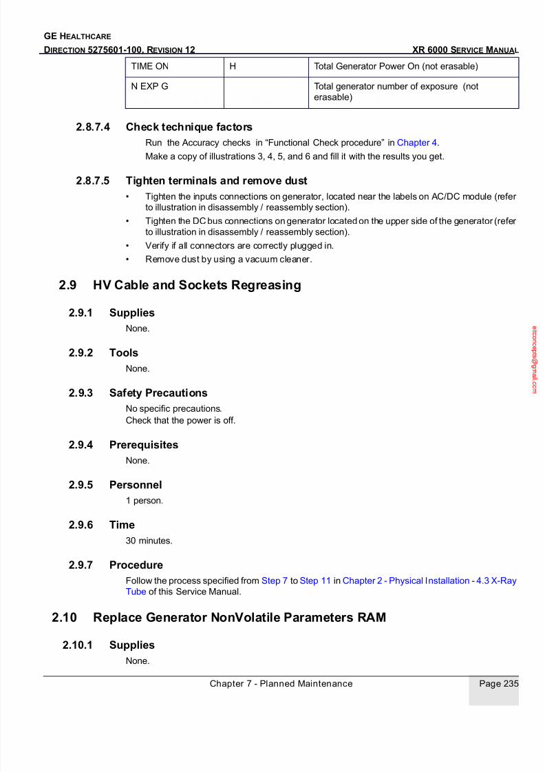
7/24/2019 GE XR6000 X-Ray - Service Manual
http://slidepdf.com/reader/full/ge-xr6000-x-ray-service-manual 235/421
Chapter 7 - Planned Maintenance Page 235
GE HEALTHCARE
DIRECTION 5275601-100, REVISION 12 XR 6000 SERVICE MANUAL
2.8.7.4 Check technique factorsRun the Accuracy checks in “Functional Check procedure” in Chapter 4.
Make a copy of illustrations 3, 4, 5, and 6 and fill it with the results you get.
2.8.7.5 Tighten terminals and remove dust• Tighten the inputs connections on generator, located near the labels on AC/DC module (refer
to illustration in disassembly / reassembly section).
• Tighten the DC bus connections on generator located on the upper side of the generator (refer
to illustration in disassembly / reassembly section).
• Verify if all connectors are correctly plugged in.
• Remove dust by using a vacuum cleaner.
2.9 HV Cable and Sockets Regreasing
2.9.1 SuppliesNone.
2.9.2 ToolsNone.
2.9.3 Safety Precautions
No specific precautions.
Check that the power is off.
2.9.4 PrerequisitesNone.
2.9.5 Personnel1 person.
2.9.6 Time
30 minutes.
2.9.7 ProcedureFollow the process specified from Step 7 to Step 11 in Chapter 2 - Physical Installation - 4.3 X-Ray
Tube of this Service Manual.
2.10 Replace Generator NonVolatile Parameters RAM
2.10.1 SuppliesNone.
TIME ON H Total Generator Power On (not erasable)
N EXP G Total generator number of exposure (not
erasable)

7/24/2019 GE XR6000 X-Ray - Service Manual
http://slidepdf.com/reader/full/ge-xr6000-x-ray-service-manual 236/421
GE HEALTHCARE
DIRECTION 5275601-100, REVISION 12 XR 6000 SERVICE MANUAL
Page 236 Section 2.0 Preventive Maintenance
2.10.2 Tools5.5 nut driver or socket wrench with ratchet.
2.10.3 Safety PrecautionsRemove power from the system before beginning work.
Check that the power is off.
To protect the circuit boards, do not forget to wear the antistatic bracelet.
2.10.4 PrerequisitesUpload the database that is stored in the RAM before starting the replacement procedure
Refer to Chapter 3 - Configuraton & Calibration - 2.9 Backup and Restore Database Parameters.
2.10.5 Personnel1 person.
2.10.6 Time
45 minutes.
2.10.7 Procedure
2.10.7.1 Remove and Replace the RAMOn the kV Control board, note the direction that the RAM faces. Insert the tip of a small screw driver
underneath left side of U32 and lever gently, then grasp it between your thumb and forefinger and
pull it directly away from its support on the board.
Insert the new Nonvolatile Parameters RAM in its place. Be careful to insert it facing in the same
direction.
Refer to Central Listing section for more details.
This NV RAM contains a LITHIUM CARBON MonoFlouride (LiCFx) battery, used to provide the
battery backup for the static RAM and the time keeper device.Electrical Characteristics: 3 V - 49
mAh type BR 1225.Resend the former component to your local GEMS representative for recycling.
2.10.7.2 Download DatabaseReapply power.
Download the database (refer to Chapter 3 - Configuraton & Calibration - 2.9 Backup and Restore
Database Parameters.).

7/24/2019 GE XR6000 X-Ray - Service Manual
http://slidepdf.com/reader/full/ge-xr6000-x-ray-service-manual 237/421
GE HEALTHCARE
DIRECTION 5275601-100, REVISION 12 XR 6000 SERVICE MANUAL
Chapter 8 - Renewal Parts Page 237
Chapter 8 - Renewal Parts
Section 1.0
Renewal Parts ListNote: Refer to Section 2.0 for information regarding JEDI Generator Renewal Parts.
Item Part No. Description Quantity/unit
1 5183178 Pioneer console assembly 12 5199452 Pioneer console E-board 13 5184620 Handswitch 14 5182285 TAV board 15 5195772 Relay DC24V 16 5195778 Power supply 150W 1
7 5195779 Power supply 320W 18 5181727 Long electromagnetism brake assembly C (tube stand
movement)
1
9 5182277 Line wheel 210 5195615 Circle electrical bracket A (up/down) 111 5191715 Tube stand top cover (50kW) 112 5181910 Pioneer tube support assembly (without clamps) 113 5181374 Tube fork clamps 114 5184986 Rotundity electricity brake assembly B (tube rotate) 115 5180983 Pioneer tube cover assembly (mechanical parts) 116 5215489 Table top 117 5184226 Long electricity brake assembly B (table top lognitudinal) 218 5184407 Table front cover 1
19 5184488 Long electricity brake assembly A (table top transverse) 320 5184750 Lock handle (table cassette tray) 121 5184895 Foot Pedal Tweak spring 222 5196542 Pioneer WS cassette tray spring kit (spring 5193827, twist
spring 5193856)
2
23 5184245 Wall Stand bottom cover 124 5184272 Wall Stand top cover 125 5195279 Switch VS10N051C2 126 5193099 MC3 MC4 cable 127 5193102 MC8 cable 128 5260909 Key switch 529 5195278 Foot pedal switch 130 5196543 Bearing kit 1 GB/T276 6001-2Z(021-0141) + 5181681 6
31 5196544 Bearing kit 2 GB/T276 6001-2Z (021-0141) + 5182435 432 021-0103 Bearing GB/T276 6200-2Z 1233 021-0129 Bearing GB/T276 6203-2Z 234 021-0102 Bearing GB/T276 6000-2Z 1935 021-0122 Bearing GB/T276 609-2Z 336 5184698 Bearing outer circle A 437 5184364 Nylon outer circle B 1238 5183903 Pioneer console power cable 139 5182354 Pioneer generator console cable 140 5212348 Table 78L 10:1 100 cm grid 141 2259298-75 Table 60L 10:1 100 cm grid 142 5308337 Tube (50kW): Toshiba E7843X 143 5213401 Wall stand with 78L 10:1 180 cm grid 1

7/24/2019 GE XR6000 X-Ray - Service Manual
http://slidepdf.com/reader/full/ge-xr6000-x-ray-service-manual 238/421
GE HEALTHCARE
DIRECTION 5275601-100, REVISION 12 XR 6000 SERVICE MANUAL
Page 238
Note: If the part 5192454 needs replacement, please order tube 5308337.
44 2226687 Wall stand with 60L 10:1 180 cm grid 145 5189248 Manual collimator 146 5136302 Collimator lamp 24V 147 5224261 Pioneer PDU breaker 148 5224263 Pioneer PDU contactor 50A 149 5224276 Pioneer PDU contactor 9A 150 5224272 Pioneer PDU Fuse kit 1
51 5224265 Relay MY2J 24VDC 152 5224548 NTC board assembly 153 5224274 Pioneer PDU transformer 550VA 254 5224275 Lose phase monitor 155 2259298-85 HV cables (8 m federal standard high voltage cable) 256 5167409-1 Table ion chamber (same as VR) 157 5167409-2 Wall stand ion chamber (same as VR) 158 5184391 Faceplate 159 5335073 Tabletop IF board 160 5184224 Photo drawer part assembly 161 5323823 Bucky Handle Assembly 162 5193838 Pioneer WS cassette tray support assembly 163 5184243 Table cassette tray 1
64 5184224 WS cassette tray 1
Item 1 Item 2
Item 3
Item 38
Item 39
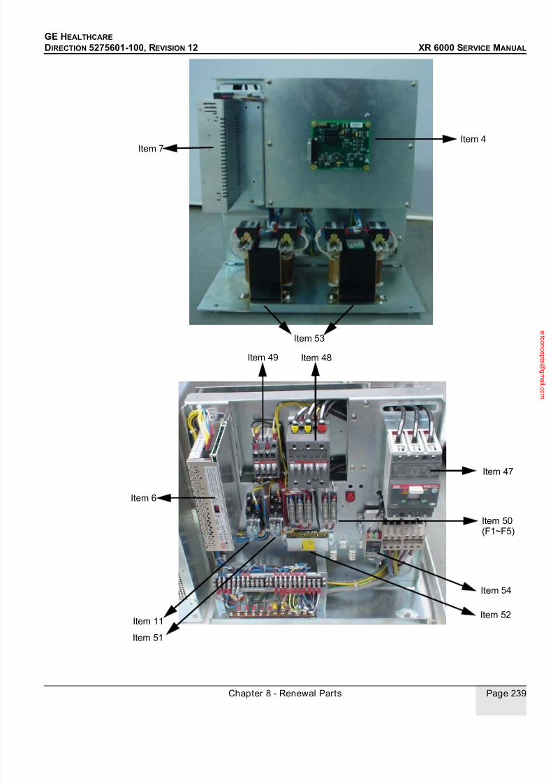
7/24/2019 GE XR6000 X-Ray - Service Manual
http://slidepdf.com/reader/full/ge-xr6000-x-ray-service-manual 239/421
GE HEALTHCARE
DIRECTION 5275601-100, REVISION 12 XR 6000 SERVICE MANUAL
Chapter 8 - Renewal Parts Page 239
Item 4Item 7
Item 53
Item 47
Item 48Item 49
Item 50(F1~F5)
Item 11
Item 6
Item 52
Item 51
Item 54

7/24/2019 GE XR6000 X-Ray - Service Manual
http://slidepdf.com/reader/full/ge-xr6000-x-ray-service-manual 240/421
GE HEALTHCARE
DIRECTION 5275601-100, REVISION 12 XR 6000 SERVICE MANUAL
Page 240
Item 8Item 30 Item 30
Item 33Item 33
Item 31
Item 31
Item 30
Item 40, 41, 43, 44
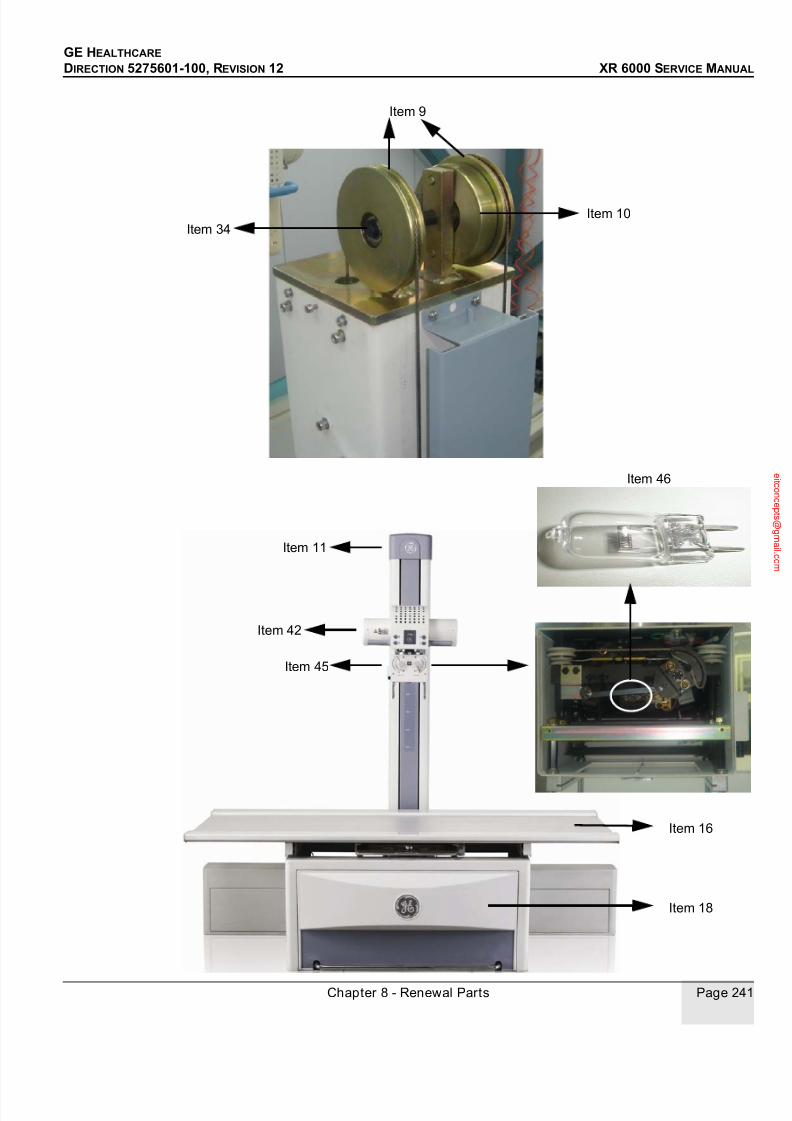
7/24/2019 GE XR6000 X-Ray - Service Manual
http://slidepdf.com/reader/full/ge-xr6000-x-ray-service-manual 241/421
GE HEALTHCARE
DIRECTION 5275601-100, REVISION 12 XR 6000 SERVICE MANUAL
Chapter 8 - Renewal Parts Page 241
Item 9
Item 10
Item 34
Item 18
Item 16
Item 42
Item 45
Item 46
Item 11

7/24/2019 GE XR6000 X-Ray - Service Manual
http://slidepdf.com/reader/full/ge-xr6000-x-ray-service-manual 242/421
GE HEALTHCARE
DIRECTION 5275601-100, REVISION 12 XR 6000 SERVICE MANUAL
Page 242
Item 15
Item 28
Item 14
Item 13
Item 12
Item 32
Two
Four TotallyFour Totally

7/24/2019 GE XR6000 X-Ray - Service Manual
http://slidepdf.com/reader/full/ge-xr6000-x-ray-service-manual 243/421
GE HEALTHCARE
DIRECTION 5275601-100, REVISION 12 XR 6000 SERVICE MANUAL
Chapter 8 - Renewal Parts Page 243
Item 17
Item 34, 37
Item 34, 37
Item 34, 37
Item 26
Item 27
Item 55

7/24/2019 GE XR6000 X-Ray - Service Manual
http://slidepdf.com/reader/full/ge-xr6000-x-ray-service-manual 244/421
GE HEALTHCARE
DIRECTION 5275601-100, REVISION 12 XR 6000 SERVICE MANUAL
Page 244
Item 19
Item 25
Item 35
Item 34, 36
Item 19Item 19
Item 21 Item 21Item 29
Item 34, 36

7/24/2019 GE XR6000 X-Ray - Service Manual
http://slidepdf.com/reader/full/ge-xr6000-x-ray-service-manual 245/421
GE HEALTHCARE
DIRECTION 5275601-100, REVISION 12 XR 6000 SERVICE MANUAL
Chapter 8 - Renewal Parts Page 245
Item 56
Item 57
Item 28
Item 20
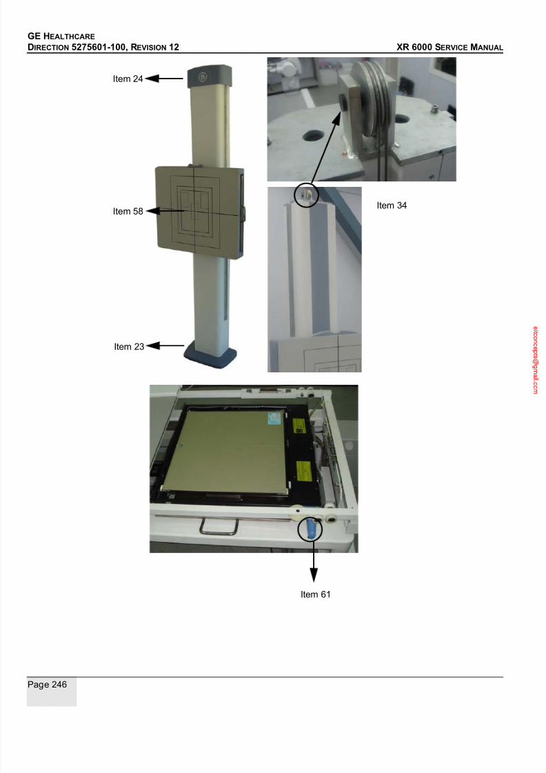
7/24/2019 GE XR6000 X-Ray - Service Manual
http://slidepdf.com/reader/full/ge-xr6000-x-ray-service-manual 246/421
GE HEALTHCARE
DIRECTION 5275601-100, REVISION 12 XR 6000 SERVICE MANUAL
Page 246
Item 34
Item 24
Item 23
Item 58
Item 61

7/24/2019 GE XR6000 X-Ray - Service Manual
http://slidepdf.com/reader/full/ge-xr6000-x-ray-service-manual 247/421
GE HEALTHCARE
DIRECTION 5275601-100, REVISION 12 XR 6000 SERVICE MANUAL
Chapter 8 - Renewal Parts Page 247
Note: If any brake is replaced, please use electric iron to seal the cable.
1.1 Bearing kit 5196543, 5196544
1.) Power off.
2.) Demount the tube stand. Please refer to Chapter 2 - Physical Installation - Section 4.0
Integrated Table - 4.2 Tube Stand
3.) Replace the bearing.
4.) Put a standard slide between the idler wheel and the eccentric cam. Then ajust the position of
the eccentric cam to assure the clearance between idler wheel and the standard slide is 0.5-
1mm with clearance gauge. See the illustration below.、
Item 22 - 5193827 Item 22 - 5193856

7/24/2019 GE XR6000 X-Ray - Service Manual
http://slidepdf.com/reader/full/ge-xr6000-x-ray-service-manual 248/421
GE HEALTHCARE
DIRECTION 5275601-100, REVISION 12 XR 6000 SERVICE MANUAL
Page 248
5.) Reinstall the tube stand.Please refer to Chapter 2 - Physical Installation - Section 4.0
Integrated Table - 4.2 Tube Stand
1.2 X-Ray Tube (5192454) / Collimator (5189248) Replacement
Note: About disassembly/reassembly of the tube assembly or collimator, please refer to Chapter 2 -Physical Installation - Section 4.0 Integrated Table - 4.3 X-Ray Tube ~ 4.4 Control Box and
Collimator .
Note: Accuracy of X-ray field and Light field alignment is required after tube or collimator replacement.
For details, please refer to Chapter 4 - Functional Checks - 4.2 Accuracy of X-Ray Field and Light
Field Alignment.
1.3 Collimator Lamp (5136302) Replacement
1.) Power off.
2.) Loose the fix knob, and rotate the collimator to the location which is convenient for operation.
Idler Wheel
Eccentric Cam
Put the standard slide here

7/24/2019 GE XR6000 X-Ray - Service Manual
http://slidepdf.com/reader/full/ge-xr6000-x-ray-service-manual 249/421
GE HEALTHCARE
DIRECTION 5275601-100, REVISION 12 XR 6000 SERVICE MANUAL
Chapter 8 - Renewal Parts Page 249
3.) Demount the back cover with four screws (two in the back cover, and two in side covers).
4.) Replace the collimator lamp.
Note: Note the former lamp’s location.
5.) Remount back cover, rotate collimator back, and tighten the fix knob.
Another Screw

7/24/2019 GE XR6000 X-Ray - Service Manual
http://slidepdf.com/reader/full/ge-xr6000-x-ray-service-manual 250/421
GE HEALTHCARE
DIRECTION 5275601-100, REVISION 12 XR 6000 SERVICE MANUAL
Page 250
Note: The collimator uses a special Collimator lamp.When the collimator lamp burns out it MUST be
replaced with the replacement lamp listed in the renewal parts section. Part number 5136302 MUST
be used as a replacement lamp. DO NOT use any other lamp as a replacement bulb as X-ray field
to Light field alignment may not meet HHS requirements.
1.4 Rotundity Electricity Brake Assembly (5184986) Replacement
Note: About disassembly/reassembly of the tube assembly, please refer to Chapter 2 - Physical
Installation - Section 4.0 Integrated Table - 4.3 X-Ray Tube ~ 4.4 Control Box and Collimator .
1.) Power off.
2.) Lower the tube assembly to the location which is convenient for operation.
3.) Disconnect all the cables of X-ray tube, collimator and control box.
4.) Rotate the tube to 180 degree, and let the X-ray window upturned.
5.) Uninstall the collimator.
6.) Uninstall the control box.
7.) Rotate the tube back.
8.) Uninstall the two upper clamps of the tube fork.9.) Remove the tube, and put it away carefully.
10.) Loosen the three fix screws on the tube arm, and demount the tube fork.
11.) Demount the fix screw.
12.) Pull out the tube arm rotation shaft.
Note: Notice the ball bearing.

7/24/2019 GE XR6000 X-Ray - Service Manual
http://slidepdf.com/reader/full/ge-xr6000-x-ray-service-manual 251/421
GE HEALTHCARE
DIRECTION 5275601-100, REVISION 12 XR 6000 SERVICE MANUAL
Chapter 8 - Renewal Parts Page 251
13.) Demount the cable clamp, disconnect the cable, and take out the rotundity electricity brake
assembly.

7/24/2019 GE XR6000 X-Ray - Service Manual
http://slidepdf.com/reader/full/ge-xr6000-x-ray-service-manual 252/421
GE HEALTHCARE
DIRECTION 5275601-100, REVISION 12 XR 6000 SERVICE MANUAL
Page 252
14.) Replace the brake, seal the cable, and fix it with cable clamp.15.) Refer to the above steps to re-install the parts.
Note: Please refer to Chapter 2 - Physical Installation - Section 6.0 Collimator Alignment to do alignment.
1.5 Wall Stand Cassette Tray Spring Kit (5196542) Replacement
1.) Power off.
2.) Take out wall stand cassette tray.
3.) Demount the two rear covers.

7/24/2019 GE XR6000 X-Ray - Service Manual
http://slidepdf.com/reader/full/ge-xr6000-x-ray-service-manual 253/421
GE HEALTHCARE
DIRECTION 5275601-100, REVISION 12 XR 6000 SERVICE MANUAL
Chapter 8 - Renewal Parts Page 253
4.) Replace the springs.
BE CAREFUL OF NOT BE SCRATCHED DURING REPLACING THE SPRINGS.
5.) Remount the covers and insert cassette tray back to wall stand.
1.6 Console Replacement
Note: Please ask customers to write down the APR parameters set by themselves.
1.) Power off.
2.) Disconnect all the cables connected to the console: power cable (J3), communication cable
(J4), and handswitch (J1).
Figure 8-1 Disconnect Console Cables
3.) Demount the handswitch socket off from the handswitch mounting plate.
4.) If console stand is ordered, please demount console off from the console stand. If not, please
skip this step.

7/24/2019 GE XR6000 X-Ray - Service Manual
http://slidepdf.com/reader/full/ge-xr6000-x-ray-service-manual 254/421
GE HEALTHCARE
DIRECTION 5275601-100, REVISION 12 XR 6000 SERVICE MANUAL
Page 254
Figure 8-2 Console Uninstallation
5.) Install the handswitch socket which is demounted before to the mounting plate on the new
console.
6.) Connect the related cables.
7.) If console stand is ordered, mount the new console onto the console stand. If not, please skip
this step.
8.) Power up.
9.) Switch to configuration mode and set the site’s system configuration.
- 32kW or 50kW
- WS AEC or not
- Table AEC or not
- Have WS or not
- Dose display or not
10.) Retrieve factory default APR database.11.) Exit configuration mode, and reset system.
1.7 Console Main Board Replacement
Note: Please ask customers to write down the APR parameters set by themselves.
1.) Power off.
2.) If console stand is ordered, please disconnect the power cable (J3) and communication cable
(J4), and demount console off from the console stand. If not, please skip this step.
Figure 8-3 Disconnect Console Cables

7/24/2019 GE XR6000 X-Ray - Service Manual
http://slidepdf.com/reader/full/ge-xr6000-x-ray-service-manual 255/421
GE HEALTHCARE
DIRECTION 5275601-100, REVISION 12 XR 6000 SERVICE MANUAL
Chapter 8 - Renewal Parts Page 255
Figure 8-4 Console Uninstallation
3.) Open the console cover with six screws.
4.) Disconnect all the cable connectors on the main board.
Note: J14 LCD cable blue side is upside in the socket.
5.) Demount the main board with 8 screws, and mount the new one.
6.) Connect all the cable connectors to the main board.
Note: J14 LCD cable blue side should be upside in the socket.
7.) Close the console cover with six screws.
8.) If console stand is ordered, mount the console onto the console stand, and connect the related
cables. If not, please skip this step.
9.) Power up.
10.) Switch to configuration mode and set the site’s system configuration.
- 32kW or 50kW
- WS AEC or not
- Table AEC or not
- Have WS or not
- Dose display or not
11.) Retrieve factory default APR database.
12.) Exit configuration mode, and reset system.
1.8 Hand Switch Replacement
1.) Power off.
2.) Disconnect the handswitch cable from J1.3.) Connect the new handswitch cable to J1.
4.) Place the new handswitch handle onto handswitch socket.
1.9 TAV Board Replacement
1.) Power off.
2.) Open table front cover.
3.) Pull out the cabinet tray.

7/24/2019 GE XR6000 X-Ray - Service Manual
http://slidepdf.com/reader/full/ge-xr6000-x-ray-service-manual 256/421
GE HEALTHCARE
DIRECTION 5275601-100, REVISION 12 XR 6000 SERVICE MANUAL
Page 256
Figure 8-5 Pull Out Cabinet Tray
4.) Demount PDU cover.
5.) Demount TAV board cover.
6.) Disconnect the communication cable connector from TAV board J1.
7.) Demount TAV board, and install the new one.
8.) Connect the communication cable.
9.) Mount the TAV board cover.
10.) Mount PDU cover.
11.) Push back the cabinet tray under the table.
Figure 8-6 Push Back Cabinet Tray
12.) Close table front cover.
Pull Here
Push Here

7/24/2019 GE XR6000 X-Ray - Service Manual
http://slidepdf.com/reader/full/ge-xr6000-x-ray-service-manual 257/421
GE HEALTHCARE
DIRECTION 5275601-100, REVISION 12 XR 6000 SERVICE MANUAL
Chapter 8 - Renewal Parts Page 257
1.10 Table Top IF Board (5335073) Replacement
1.) The default setting for DIP switch S3 as
2.) Set DIP switch as following before installing
Section 2.0 JEDI Generator Renewal Parts
2.1 Introduction
This Section provides information for the identification of Renewal Parts for the JEDI 50 R 1T
generator.
2.2 JEDI Generator Renewal Parts List
Table 8-1
DIP-Switch bit 1 2 3 4
XR6000 On On On On
Table 8-2
DIP-Switch bit 1 2 3 4
XR6000 On On On Off
Part No. Description Quantity
/Unit
2212259-2 Generator (Jedi 50 R1T) 1
2409043 Rotation Board JEDI Program V3.02 1
5126988-2 LVPS 3PH V3 1
5126989 Mid Power Inverter Assy 1
5126994-3 Programmed kV Control Board P 3.2 1
5126997 AC/DC 3PH Board Assy 1
5126999 EMC Filter 1
2217057 First Aid Spare 1
2214527 HV Tank (ref: 2186730 FRU order is 2214527) 1
2184567-4 RAD I/F Board 1
5119911 AEC Board 1
2409047 Filament Board 1
99185290 Fuse 15A 1

7/24/2019 GE XR6000 X-Ray - Service Manual
http://slidepdf.com/reader/full/ge-xr6000-x-ray-service-manual 258/421
GE HEALTHCARE
DIRECTION 5275601-100, REVISION 12 XR 6000 SERVICE MANUAL
Page 258 Section 2.0 JEDI Generator Renewal Parts
2.3 FRU Information
Information shown for each FRU (Field Replaceable Unit) is explained below.
Wherever possible, the FRU or its position is illustrated for easy identification.
2121569 Power bridge 1
2200700 Inverter Coils Mid Power Assy 1
2159419 Non-Volatile parameters RAM 1
2208000 Assy AEC cable 1
2198191 KV Measure - KV Control cable 1
2215903 ROT/LVPS/Heater cable 1
2214511 System cable 1
5133341 Capa Inverter Assy 2
2202419 I/F RAD - AEC cable (option) 1
2202418 KV control - I/F RAD cable 1
2221983 CAN cable 1
2198185 KV Measure - Gate Command cable 1
Inverter PW Assembly
Inverter Capa Assembly
2203900
FRU name
Part number forordering
Notes. These may include:Reference to an illustration with more informationReference to a relevant Disassembly/ReassemblyJob Card Items included with the FRU etc.
Items shown in this way areincluded in the FRU shownimmediately above, but may also beordered separately.
2187001

7/24/2019 GE XR6000 X-Ray - Service Manual
http://slidepdf.com/reader/full/ge-xr6000-x-ray-service-manual 259/421
GE HEALTHCARE
DIRECTION 5275601-100, REVISION 12 XR 6000 SERVICE MANUAL
Chapter 8 - Renewal Parts Page 259
2.4 Jedi 50 R 1T Structure
JEDI 50 R 1T
2212259-2
JEDI STD HV Tank2214527
Module Auxiliaries 50 R 1T
2215808
Module Power 50 R 1T2229597
AEC I/F Cable2202419
First Aid Spares2217057
Equipped AC/DC 50 R 1T
2221722
Power Unit HLB2214447-2
Interface Module 50 R 1T
2205629-2
AEC Board (option)2204112-2
System cable2214511
CAN Cable2221983
Service Tools2228546

7/24/2019 GE XR6000 X-Ray - Service Manual
http://slidepdf.com/reader/full/ge-xr6000-x-ray-service-manual 260/421
GE HEALTHCARE
DIRECTION 5275601-100, REVISION 12 XR 6000 SERVICE MANUAL
Page 260 Section 2.0 JEDI Generator Renewal Parts
2.5 Renewal Parts
Figure 8-7 JEDI 50 R 1T Generator Location of Main Assemblies
Miscellaneous Items:
First aid spares: Services tools
1 short circuit cable Service software, 2227656
1 fuse 15 A 700 VDC RS232 Cable, 2207478
1 fuse 10 A 250 V
10 M4-8 mm screws
10 tie-wraps
TOP VIEW
REAR VIEW
AC/DC Unit
AC/DC Unit
Power Unit
Power Unit
Interface Unit
Auxiliary Unit
InterfaceUnit
Auxiliary Unit
Jedi StandardHV Tank

7/24/2019 GE XR6000 X-Ray - Service Manual
http://slidepdf.com/reader/full/ge-xr6000-x-ray-service-manual 261/421
GE HEALTHCARE
DIRECTION 5275601-100, REVISION 12 XR 6000 SERVICE MANUAL
Chapter 8 - Renewal Parts Page 261
Figure 8-8 JEDI 50 R 1T AC/DC Unit, Interface Unit & Auxiliary Unit
AC/DC Unit
AC/DC 3 Phase Mid PowerAssy (Board & Rectifier+ 2 cables)
2214995FRU: 1Job Card D/R JEDI 17-30
EMC Filter Board2209840FRU: 1Job Card D/R JEDI 17-29
Interface Unit
AEC Board V12184569-2 AEC Board V22222253FRU: 1Job Card D/R JEDI 17-36
RAD I/F Board V12184567-4RAD I/F Board V2 2226456FRU: 1Job Card D/R JEDI 17-25
Auxiliary Unit
Rotor Board High Speed2214605-3FRU: 1Job Card D/R JEDI 17-35
Filament Board 1 Inv.2214604FRU: 1Job Card D/R JEDI 17-34
LV Power Supply 3 Ph Board2212166FRU: 1Job Card D/R JEDI 17-33
5126999
5126997
5119911
2409043
5126988-2
2409047

7/24/2019 GE XR6000 X-Ray - Service Manual
http://slidepdf.com/reader/full/ge-xr6000-x-ray-service-manual 262/421
GE HEALTHCARE
DIRECTION 5275601-100, REVISION 12 XR 6000 SERVICE MANUAL
Page 262 Section 2.0 JEDI Generator Renewal Parts
Figure 8-9 JEDI 50 R 1T Power Unit
Jedi Standard HV Tank2214527FRU: 1Job Card D/R JEDI 17-23
Inverter Mid Power Assy2215814FRU: 1Job Card D/R JEDI 17-24
A
Capa Inverter Assy2229505FRU: 2Job Card D/R JEDI 17-32
Inverter Coils Mid Power Assy2200700FRU: 2Job Card D/R JEDI 17-31
Programmed kV ControlBoard2214606-2FRU: 1Job Card D/R JEDI 17-26
Non-Volatile parametersRAM2159419FRU: 2Job Card PM JEDI 15-2
A
5133341
5126994-3
5126989
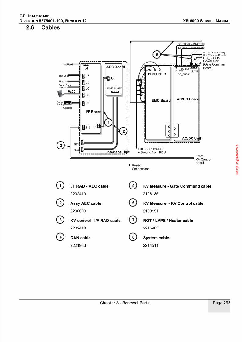
7/24/2019 GE XR6000 X-Ray - Service Manual
http://slidepdf.com/reader/full/ge-xr6000-x-ray-service-manual 263/421
GE HEALTHCARE
DIRECTION 5275601-100, REVISION 12 XR 6000 SERVICE MANUAL
Chapter 8 - Renewal Parts Page 263
2.6 Cables
I/F RAD - AEC cable KV Measure - Gate Command cable
2202419 2198185
Assy AEC cable KV Measure - KV Control cable
2208000 2198191
KV control - I/F RAD cable ROT / LVPS / Heater cable
2202418 2215903
CAN cable System cable2221983 2214511
AC/DC Board
I/F Board
Interface Unit
EMC Board
AC/DC Unit
KeyedConnections
PH3PH2PH1
Not Used
Not Used
Not Used
Room Door Interface
Console
AEC1
AEC2
AEC Board
DC_BUS N to INVERTER
DC_BUS P to INVERTER
DC_BUS toPower Unit(Gate Comman
DC_BUS-DC_BUS+
PH3
PH2
PH1
DC_BUS M
THREE PHASES+ Ground from PDU
J4
J1
J1J2J3
J3
J2&TP2J1&TP1
9pts
J7
J5
J6
J8
J9
9pts
9pts
9pts
9pts
25pts
J1064pts
16ptsJ3
16pts
J5
9pts9ptsW22
9pts
9pts
ServiceLaptop
DC_BUS to AuxiliaryUnit (Rotation Board)
Board)
FromKV Controlboard
2
8
1
3
1
2
3
8
1 5
2 6
3 7
4 8
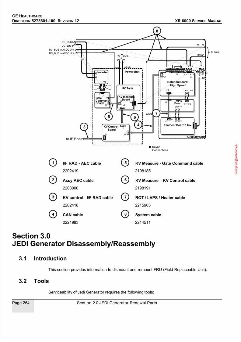
7/24/2019 GE XR6000 X-Ray - Service Manual
http://slidepdf.com/reader/full/ge-xr6000-x-ray-service-manual 264/421
GE HEALTHCARE
DIRECTION 5275601-100, REVISION 12 XR 6000 SERVICE MANUAL
Page 264 Section 2.0 JEDI Generator Renewal Parts
I/F RAD - AEC cable KV Measure - Gate Command cable
2202419 2198185
Assy AEC cable KV Measure - KV Control cable
2208000 2198191
KV control - I/F RAD cable ROT / LVPS / Heater cable
2202418 2215903
CAN cable System cable
2221983 2214511
Section 3.0
JEDI Generator Disassembly/Reassembly
3.1 Introduction
This section provides information to dismount and remount FRU (Field Replaceable Unit).
3.2 Tools
Serviceability of Jedi Generator requires the following tools:
26 pts
CANJ2
134911 56
1Inverter
Auxiliary Unit
Gate
KV Control
Power Unit
HV Tank
KV Measure
LVPS
Rotation Board
Filament Board 1 Inv.
DC_BUS N
DC_BUS P
DC_BUS to ACDC Unit J1
DC_BUS to ACDC Unit J3
NP
KeyedConnections
ILr ILp
blue
grey red
grey
1
1
1
to Tube
J4
1
J3
J1
J2
J3
J1
J1
J2J3
anode cathode
to IF Board
to Tube
Rotor
J1J2
J3
J1A CF-N CF-P
CF1CF2
- + A C P- +
J2A
J1 CF1CF2
1 CF3CF4
1
CAN
J2CommandBoard
Board
Board
High Speed
Board
64pts
50pts
26pts
50pts
34pts
26pts
26pts
26pts
26pts
LF0
SF
34pts
70 o C
1 11
8
5 6
34
7
8
3
5 6
4
7
1 5
2 6
3 7
4 8

7/24/2019 GE XR6000 X-Ray - Service Manual
http://slidepdf.com/reader/full/ge-xr6000-x-ray-service-manual 265/421
GE HEALTHCARE
DIRECTION 5275601-100, REVISION 12 XR 6000 SERVICE MANUAL
Chapter 8 - Renewal Parts Page 265
Digital Multimeter (A)
Phillips Screwdriver (B)
Allen Key (C)
Screwdriver With Interchangeable Socket Head (D)
Long Extension for Ratchet Wrench (E)
Short Extension for Ratchet Wrench (F)
Cutting Pliers (G)
High Voltage Wrench (H)
Ratchet Wrench (I)
Socket Wrench (J)
Hexagonal Head Socket Set (K)
3.3 HV Tank, 1 Tube, 1-3 Phase
3.3.1 SuppliesNone
3.3.2 Tools• 5.5 mm nut driver or socket wrench with ratchet.
• 3 mm Allen wrench.
• 13 mm socket with ratchet.
3.3.3 Safety Precautions
BEFORE ANY MANUAL INTERVENTION, ENSURE THE MAIN POWER IS OFF. APPLY LOCKOUT - TAG OUT PROCEDURE FOR YOUR OWN SAFETY WHEN MANIPULATING INSIDE THEEQUIPMENT IS REQUIRED.To protect the circuit boards, do not forget to wear the antistatic bracelet.
3.3.4 PrerequisitesRemove the generator from the table and put it on its bottom side on the floor or on a work bench.
a
B
C
D
E
F
G
H
I
J
K
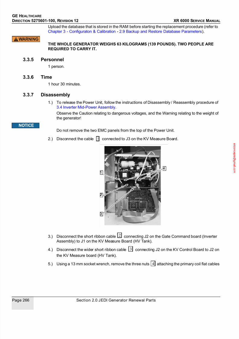
7/24/2019 GE XR6000 X-Ray - Service Manual
http://slidepdf.com/reader/full/ge-xr6000-x-ray-service-manual 266/421
GE HEALTHCARE
DIRECTION 5275601-100, REVISION 12 XR 6000 SERVICE MANUAL
Page 266 Section 2.0 JEDI Generator Renewal Parts
Upload the database that is stored in the RAM before starting the replacement procedure (refer to
Chapter 3 - Configuraton & Calibration - 2.9 Backup and Restore Database Parameters).
THE WHOLE GENERATOR WEIGHS 63 KILOGRAMS (139 POUNDS). TWO PEOPLE AREREQUIRED TO CARRY IT.
3.3.5 Personnel1 person.
3.3.6 Time1 hour 30 minutes.
3.3.7 Disassembly
1.) To release the Power Unit, follow the instructions of Disassembly / Reassembly procedure of
3.4 Inverter Mid-Power Assembly.
Observe the Caution relating to dangerous voltages, and the Warning relating to the weight of
the generator!
Do not remove the two EMC panels from the top of the Power Unit.
2.) Disconnect the cable connected to J3 on the KV Measure Board.
3.) Disconnect the short ribbon cable connecting J2 on the Gate Command board (Inverter Assembly) to J1 on the KV Measure Board (HV Tank).
4.) Disconnect the wider short ribbon cable connecting J2 on the KV Control Board to J2 on
the KV Measure board (HV Tank).
5.) Using a 13 mm socket wrench, remove the three nuts attaching the primary coil flat cables
1
2
3
4
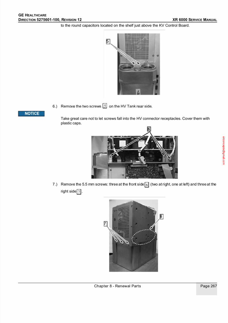
7/24/2019 GE XR6000 X-Ray - Service Manual
http://slidepdf.com/reader/full/ge-xr6000-x-ray-service-manual 267/421
GE HEALTHCARE
DIRECTION 5275601-100, REVISION 12 XR 6000 SERVICE MANUAL
Chapter 8 - Renewal Parts Page 267
to the round capacitors located on the shelf just above the KV Control Board.
6.) Remove the two screws on the HV Tank rear side.
Take great care not to let screws fall into the HV connector receptacles. Cover them with
plastic caps.
7.) Remove the 5.5 mm screws: three at the front side (two at right, one at left) and three at the
right side .
5
6
6
7

7/24/2019 GE XR6000 X-Ray - Service Manual
http://slidepdf.com/reader/full/ge-xr6000-x-ray-service-manual 268/421
GE HEALTHCARE
DIRECTION 5275601-100, REVISION 12 XR 6000 SERVICE MANUAL
Page 268 Section 2.0 JEDI Generator Renewal Parts
8.) At the rear side, remove the eight 3 mm Allen screws which secure the heat sink of the
Inverter Mid Power Assembly to the HV Tank.
9.) Take off the assembly constitued by five parts: EMC covers, Coils Inverter Assy, Capa Inverter
Assy, Mid Power Assy and KV Control Board. The HV Tank is now free .
3.3.8 ReassemblyReverse the disassembly procedure to reassemble and replace the unit.
1.) Mount the flat cable J1 on the kV Measure Board of the new HV Tank (refer to (refer to
Disassembly section ).
2.) Reassemble the HV Tank with the other elements of the Power Unit (refer to Disassembly
section ).3.) Mount the eight 3 mm Allen screws to secure the heat sink of the Inverter Mid Power Assembly
to the HV Tank. (refer to section Disassembly ).
Tighten to torque 8 N.m (80 kg.cm).
4.) Put back the 3 front 5.5 mm hex head screws (refer to section Disassembly ), one at the
left side,two at the right side.
Tighten them between 1.5 to 2 N.m (15 to 20 kg.cm).
5.) Reconnect the short ribbon cable from J1 on the KV Measure board to J2 on the Gate
Command board (refer to section Disassembly ).
6.) Using the 13 mm socket wrench, connect the primary coil flat cables to the three capacitors
8
9
9
2
9
8
6
2
1

7/24/2019 GE XR6000 X-Ray - Service Manual
http://slidepdf.com/reader/full/ge-xr6000-x-ray-service-manual 269/421
GE HEALTHCARE
DIRECTION 5275601-100, REVISION 12 XR 6000 SERVICE MANUAL
Chapter 8 - Renewal Parts Page 269
).
The two flat cables with white bands on them go both together on the middle capacitor
with the parallel resonant cable (refer to section Reassembly ).
7.) Reconnect the cable to J3 on the KV Measure Board (refer to section Disassembly ).
Tighten the nuts to 8 N.m (80 kg.cm).
8.) Reconnect the wider short ribbon cable from J2 on the kV Control board to J2 on the kV
Measure Board (refer to section Disassembly ).
9.) Mount the two 5.5 hex head screws securing the cover to the HV Tank on the HV outlet side
(refer to section Disassembly ) and the three screws on the other side (refer to sectionDisassembly ).
Tighten the screws between 1.5 to 2 N.m (15 to 20 kg.cm).
10.) Mount the Power Unit on the support plate.
THE POWER UNIT WEIGHTS 30 KG (66 POUNDS).
11.) Refer to Disassembly / Reassembly procedure of 3.4 Inverter Mid-Power Assembly to
complete reassembly of the Unit.
12.) Put 5 cl of oil into the HV receptacles. Reconnect the HV cables.
3.3.9 VerifyConnect the service laptop (refer to Chapter 3 - Configuraton & Calibration - 2.3 Service Software
User Guide) and proceed to "HV no load diagnostics" to ensure correct operation.
Skip steps "Gate Command and Inverter in Short Circuit" diagnostics.
3.4 Inverter Mid-Power Assembly
3.4.1 SuppliesNone
1
2
2
1
3
57
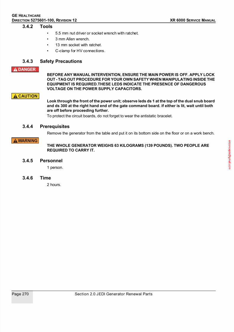
7/24/2019 GE XR6000 X-Ray - Service Manual
http://slidepdf.com/reader/full/ge-xr6000-x-ray-service-manual 270/421
GE HEALTHCARE
DIRECTION 5275601-100, REVISION 12 XR 6000 SERVICE MANUAL
Page 270 Section 2.0 JEDI Generator Renewal Parts
3.4.2 Tools• 5.5 mm nut driver or socket wrench with ratchet.
• 3 mm Allen wrench.
• 13 mm socket with ratchet.
• C-clamp for HV connections.
3.4.3 Safety Precautions
BEFORE ANY MANUAL INTERVENTION, ENSURE THE MAIN POWER IS OFF. APPLY LOCKOUT - TAG OUT PROCEDURE FOR YOUR OWN SAFETY WHEN MANIPULATING INSIDE THEEQUIPMENT IS REQUIRED.THESE LEDS INDICATE THE PRESENCE OF DANGEROUSVOLTAGE ON THE POWER SUPPLY CAPACITORS.
Look through the front of the power unit; observe leds ds 1 at the top of the dual snub boardand ds 300 at the right hand end of the gate command board. if either is lit, wait until bothare off before proceeding further.
To protect the circuit boards, do not forget to wear the antistatic bracelet.
3.4.4 PrerequisitesRemove the generator from the table and put it on its bottom side on the floor or on a work bench.
THE WHOLE GENERATOR WEIGHS 63 KILOGRAMS (139 POUNDS). TWO PEOPLE AREREQUIRED TO CARRY IT.
3.4.5 Personnel1 person.
3.4.6 Time2 hours.

7/24/2019 GE XR6000 X-Ray - Service Manual
http://slidepdf.com/reader/full/ge-xr6000-x-ray-service-manual 271/421
GE HEALTHCARE
DIRECTION 5275601-100, REVISION 12 XR 6000 SERVICE MANUAL
Chapter 8 - Renewal Parts Page 271
3.4.7 Disassembly
Figure 8-10 JEDI 50 R 1T Generator General View
1
2
3
4
5
TOP VIEW
3
4
3
1
4
2
5
1
2
TABLE BUCKY
WALL BUCKY
DOOR LAP TOP
CONSOLEAEC1AEC2
TABLE BUCKYWALL BUCKYDOORLAPTOPCONSOLE
AEC2 AEC1
1
2
3
4
5
AC/DC UNIT
POWER UNIT
INTERFACE UNIT
AUXILIARY UNIT
SUPPORT PLATE
FRONT VIEW
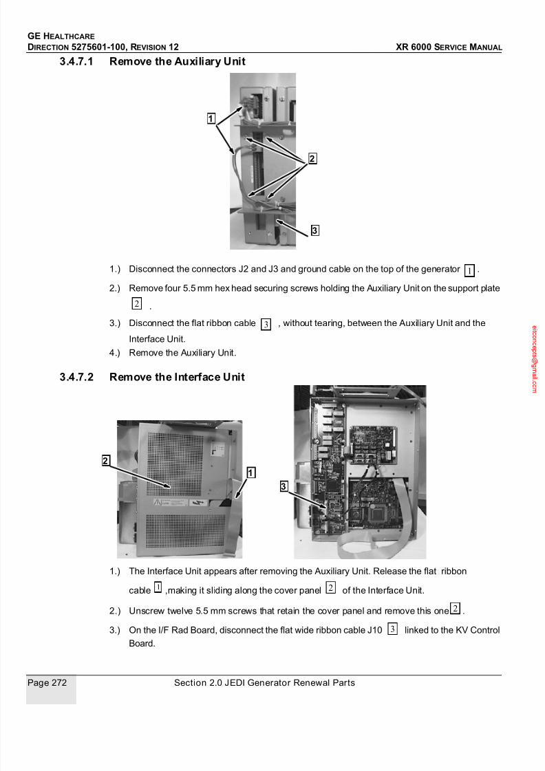
7/24/2019 GE XR6000 X-Ray - Service Manual
http://slidepdf.com/reader/full/ge-xr6000-x-ray-service-manual 272/421
GE HEALTHCARE
DIRECTION 5275601-100, REVISION 12 XR 6000 SERVICE MANUAL
Page 272 Section 2.0 JEDI Generator Renewal Parts
3.4.7.1 Remove the Auxiliary Unit
1.) Disconnect the connectors J2 and J3 and ground cable on the top of the generator .
2.) Remove four 5.5 mm hex head securing screws holding the Auxiliary Unit on the support plate
.
3.) Disconnect the flat ribbon cable , without tearing, between the Auxiliary Unit and the
Interface Unit.
4.) Remove the Auxiliary Unit.
3.4.7.2 Remove the Interface Unit
1.) The Interface Unit appears after removing the Auxiliary Unit. Release the flat ribbon
cable ,making it sliding along the cover panel of the Interface Unit.
2.) Unscrew twelve 5.5 mm screws that retain the cover panel and remove this one .
3.) On the I/F Rad Board, disconnect the flat wide ribbon cable J10 linked to the KV Control
Board.
1
2
3
1
2
3
12
3
1 2
2
3

7/24/2019 GE XR6000 X-Ray - Service Manual
http://slidepdf.com/reader/full/ge-xr6000-x-ray-service-manual 273/421
GE HEALTHCARE
DIRECTION 5275601-100, REVISION 12 XR 6000 SERVICE MANUAL
Chapter 8 - Renewal Parts Page 273
THE POWER UNIT WEIGHTS 30 KILOGRAMS (66 POUNDS). DO NOT TRY TO LIFT ITWITHOUT ASSISTANCE.
4.) Unscrew twelve 5.5 mm screws securing the Interface Unit box to the Power box.
5.) Taking care of the flat wide ribbon cable ,remove the Interface Unit box. The components
of the Power Unit appear: coils assembly, capacitors assembly, KV Control Board.
3.4.7.3 Remove the AC/DC Unit and the support plate
1.) On the top of the generator, the two connectors are fixed mecanically on the support
plate. Unscrew connectors screws in order to release the 4 power cables coming fromthe Power Unit and the AC/DC Unit.
2.) Remove the screw securing the ground cable on the AC/DC Unit. Disconnect the cable
linking the AC/DC Unit and the Power Unit .
3.) Remove the four screws on the support plate in order to release the Power Unit. This one
is then free.
3
3
1
2
3
4
5
2
5
1
2
3
4
5

7/24/2019 GE XR6000 X-Ray - Service Manual
http://slidepdf.com/reader/full/ge-xr6000-x-ray-service-manual 274/421
GE HEALTHCARE
DIRECTION 5275601-100, REVISION 12 XR 6000 SERVICE MANUAL
Page 274 Section 2.0 JEDI Generator Renewal Parts
3.4.7.4 Remove the Inverter Mid Power Assembly
1.) Remove the 5.5 mm hex head screws which secure the two EMC cover panels at each
side of the Power Unit; remove the panels.
2.) With a 10 mm socket wrench with ratchet ,remove the three hex head screws securing the
2
3
1
1
2

7/24/2019 GE XR6000 X-Ray - Service Manual
http://slidepdf.com/reader/full/ge-xr6000-x-ray-service-manual 275/421
GE HEALTHCARE
DIRECTION 5275601-100, REVISION 12 XR 6000 SERVICE MANUAL
Chapter 8 - Renewal Parts Page 275
cables Q100C , Q100E and Q200C on the Inverter Mid Power Assembly.
3.) Disconnect flat ribbon cables from J1 and J3 on the Gate Command Board and
disconnnect J4 at the right hand side of the board.
4.) With 10 mm wrench, disconnect the parallel Coil connection from the Current Transformer
pass through and with 13 mm wrench the other connection from the Capacitor
Assembly .
5.) Remove the eight 3 mm Allen screws which secure the Inverter Mid Power Assembly to
the HV Tank.
3
5
6
7
8
A
A
4
5
6
7

7/24/2019 GE XR6000 X-Ray - Service Manual
http://slidepdf.com/reader/full/ge-xr6000-x-ray-service-manual 276/421
GE HEALTHCARE
DIRECTION 5275601-100, REVISION 12 XR 6000 SERVICE MANUAL
Page 276 Section 2.0 JEDI Generator Renewal Parts
6.) Remove the Inverter Mid Power Assembly .
3.4.8 Reassembly
1.) Present the new Inverter assembly. Put back the eight 3 mm Allen screws to secure the
Inverter Mid Power assembly to the HV Tank (refer to section 3.4 Inverter Mid-Power
Assembly ).
Tighten them firmly to torque 2 N.m (20 kg.cm).
2.) Remount all cables that were removed:
a.) Remount the three Coil cables on the Inverter IGBT's with three 5.5 mm screws.
Tighten them firmly to torque 3 N.m (30 kg.cm).
RESPECT THE ORIENTATION OF THE CABLES TO THE IGBTS CONNECTIONS TOAVOID CABLE CONTACT WITH TOP COVER.
b.) Reconnect the short flat cable between the HV Tank and the Gate Command board (J3),
and the inverter current feedback cable (J1) on the Gate Command board (refer to
section 3.4 Inverter Mid-Power Assembly ).
c.) Reconnect the DC bus cable to J4 to the right hand side of the Gate Command board.
d.) With the 10 mm screw and flat and lock washer, reconnect the shorter cable of the parallel
coil on the Inverter assembly onto the right hand side current transformer (Ti1/100) pass
through. .
Tighten to 3 N.m (30 kg.cm) torque.
8
7
4
Top J4 -+
A

7/24/2019 GE XR6000 X-Ray - Service Manual
http://slidepdf.com/reader/full/ge-xr6000-x-ray-service-manual 277/421
GE HEALTHCARE
DIRECTION 5275601-100, REVISION 12 XR 6000 SERVICE MANUAL
Chapter 8 - Renewal Parts Page 277
e.) With the 13 mm screw, with flat and lock washer, reconnect the longer cable of the coil
on the central capacitor (C3UF) of the Capacitor assembly, together with the two primary
HV Transformer flat wires (the two with a white ring).
Tighten to 8 N.m (80 kg.cm) torque.
3.) Perform an overall inspection before proceeding. Use the following illustration to check the
connections are right.
B
B

7/24/2019 GE XR6000 X-Ray - Service Manual
http://slidepdf.com/reader/full/ge-xr6000-x-ray-service-manual 278/421
GE HEALTHCARE
DIRECTION 5275601-100, REVISION 12 XR 6000 SERVICE MANUAL
Page 278 Section 2.0 JEDI Generator Renewal Parts
4.) Remount the two EMC panels on the top of Power Unit with the 5.5 hex head screws.
Tighten all the cover screws to torque between 1.5 to 2 N.m (15 to 20 kg.cm)
5.) Assemble the Power Unit with the AC/DC Unit on the support plate with 5.5 mm hex head
screws. Put back in place the disconnected cables: ground, DC bus (refer to section 3.4
Inverter Mid-Power Assembly).
6.) Remount the Interface Unit on the support plate then the Auxiliary Unit. Follow the inverse
procedure indicated in the sections and .
7.) Remount the generator inside the table.
3.4.9 VerifyRun HV LOAD DIAGNOSTIC - "Inverter in Short Circuit Diagnostics" and "Inverter Gate Command
Diagnostic" are not pre-requested.
Verify correct operation on the whole application range.
3.5 I/F Board RAD
3.5.1 SuppliesNone
+ -
C
E E
C
HV Tank
Capa Assembly
Coil Assembly
Inverter Assembly
Q100C Q200C
Q100E
+ DC - DC Ti1/40 Ti1/100
Parallel Coil
C3UF
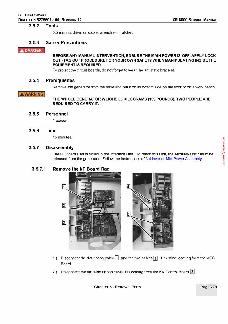
7/24/2019 GE XR6000 X-Ray - Service Manual
http://slidepdf.com/reader/full/ge-xr6000-x-ray-service-manual 279/421
GE HEALTHCARE
DIRECTION 5275601-100, REVISION 12 XR 6000 SERVICE MANUAL
Chapter 8 - Renewal Parts Page 279
3.5.2 Tools5.5 mm nut driver or socket wrench with ratchet.
3.5.3 Safety Precautions
BEFORE ANY MANUAL INTERVENTION, ENSURE THE MAIN POWER IS OFF. APPLY LOCKOUT - TAG OUT PROCEDURE FOR YOUR OWN SAFETY WHEN MANIPULATING INSIDE THEEQUIPMENT IS REQUIRED.To protect the circuit boards, do not forget to wear the antistatic bracelet.
3.5.4 PrerequisitesRemove the generator from the table and put it on its bottom side on the floor or on a work bench.
THE WHOLE GENERATOR WEIGHS 63 KILOGRAMS (139 POUNDS). TWO PEOPLE AREREQUIRED TO CARRY IT.
3.5.5 Personnel1 person.
3.5.6 Time15 minutes.
3.5.7 DisassemblyThe I/F Board Rad is situed in the Interface Unit. To reach this Unit, the Auxiliary Unit has to be
released from the generator. Follow the instructions of 3.4 Inverter Mid-Power Assembly.
3.5.7.1 Remove the I/F Board Rad
1.) Disconnect the flat ribbon cable and the two cables , if existing, coming from the AEC
Board.
2.) Disconnect the flat wide ribbon cable J10 coming from the KV Control Board .
4
5
1
2
3
1 2
3

7/24/2019 GE XR6000 X-Ray - Service Manual
http://slidepdf.com/reader/full/ge-xr6000-x-ray-service-manual 280/421
GE HEALTHCARE
DIRECTION 5275601-100, REVISION 12 XR 6000 SERVICE MANUAL
Page 280 Section 2.0 JEDI Generator Renewal Parts
3.) Remove the four screws of connectors J8 and J9 .
4.) Remove the ten 5.5 mm screws securing the Interface Board Rad; remove the board.
3.5.8 Reassembly
1.) Reverse the disassembly procedure to reassemble the unit. Tighten screws to torque between1.5 and 2 N.m (15 to 20 kg.cm).
2.) Power the system on and verify that the system functions properly.
3.6 KV Board RAD
3.6.1 SuppliesNone
3.6.2 Tools• 5.5 mm nut driver or socket wrench with ratchet.
• 10 mm Allen wrench.
• 13 mm socket with ratchet.
3.6.3 Safety Precautions
BEFORE ANY MANUAL INTERVENTION, ENSURE THE MAIN POWER IS OFF. APPLY LOCKOUT - TAG OUT PROCEDURE FOR YOUR OWN SAFETY WHEN MANIPULATING INSIDE THEEQUIPMENT IS REQUIRED.
To protect the circuit boards, do not forget to wear the antistatic bracelet.
3.6.4 PrerequisitesRemove the generator from the table and put it on its bottom side on the floor or on a work bench.
THE WHOLE GENERATOR WEIGHS 63 KILOGRAMS (139 POUNDS). TWO PEOPLE AREREQUIRED TO CARRY IT.The KV Control board contains a saved memory Database with essentially the following
parameters:
• Tube configuration parameters, AEC calibration parameters, and Room configuration
(workstation, AEC, screen film pairs).
• Filament aging variable
• Error Log• Recorded parameter data
If it is possible, backup database first. Else, the diagram hereafter helps you to determine the action
to take for your situation.
4
5
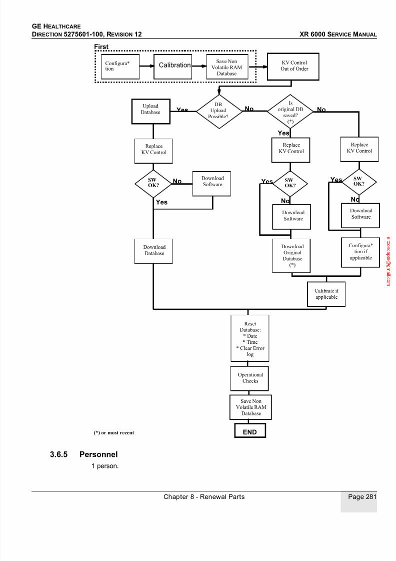
7/24/2019 GE XR6000 X-Ray - Service Manual
http://slidepdf.com/reader/full/ge-xr6000-x-ray-service-manual 281/421
GE HEALTHCARE
DIRECTION 5275601-100, REVISION 12 XR 6000 SERVICE MANUAL
Chapter 8 - Renewal Parts Page 281
3.6.5 Personnel1 person.
KV Control
Out of Order
No
First
DBUpload
Possible?
No
Yes
Isoriginal DB
saved?
(*)
Upload
Database
SW OK?
No
Replace
KV Control
Download
Software
Yes
Download
Database
Reset
Database:
* Date
* Time
* Clear Errorlog
Replace
KV Control
SW OK?
No
Yes
END
Operational
Checks
SWOK?
No
Yes
Save Non
Volatile RAM
Database
Configura*
tion if
applicable
Save Non
Volatile RAM
Database
CalibrationConfigura* tion
Download
Original
Database
(*)
Yes
(*) or most recent
Calibrate if
applicable
Replace
KV Control
Download
Software
Download
Software
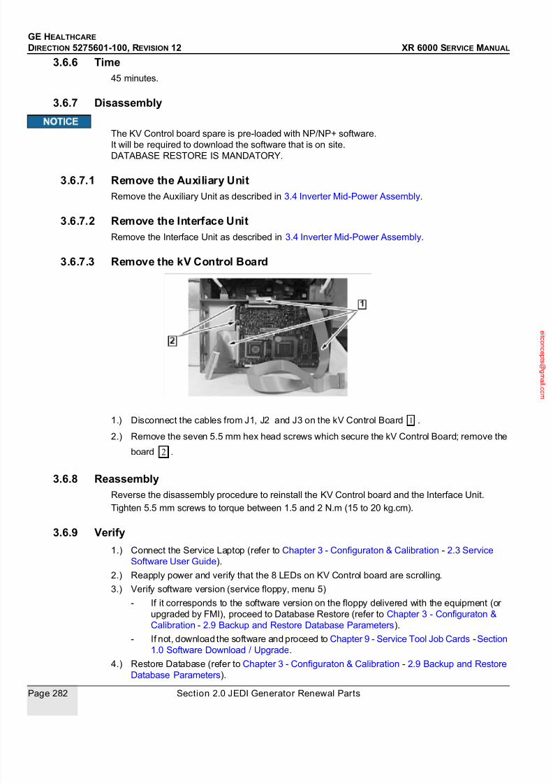
7/24/2019 GE XR6000 X-Ray - Service Manual
http://slidepdf.com/reader/full/ge-xr6000-x-ray-service-manual 282/421
GE HEALTHCARE
DIRECTION 5275601-100, REVISION 12 XR 6000 SERVICE MANUAL
Page 282 Section 2.0 JEDI Generator Renewal Parts
3.6.6 Time45 minutes.
3.6.7 Disassembly
The KV Control board spare is pre-loaded with NP/NP+ software.It will be required to download the software that is on site.
DATABASE RESTORE IS MANDATORY.
3.6.7.1 Remove the Auxiliary UnitRemove the Auxiliary Unit as described in 3.4 Inverter Mid-Power Assembly.
3.6.7.2 Remove the Interface UnitRemove the Interface Unit as described in 3.4 Inverter Mid-Power Assembly.
3.6.7.3 Remove the kV Control Board
1.) Disconnect the cables from J1, J2 and J3 on the kV Control Board .
2.) Remove the seven 5.5 mm hex head screws which secure the kV Control Board; remove the
board .
3.6.8 ReassemblyReverse the disassembly procedure to reinstall the KV Control board and the Interface Unit.
Tighten 5.5 mm screws to torque between 1.5 and 2 N.m (15 to 20 kg.cm).
3.6.9 Verify
1.) Connect the Service Laptop (refer to Chapter 3 - Configuraton & Calibration - 2.3 ServiceSoftware User Guide).
2.) Reapply power and verify that the 8 LEDs on KV Control board are scrolling.
3.) Verify software version (service floppy, menu 5)
- If it corresponds to the software version on the floppy delivered with the equipment (or
upgraded by FMI), proceed to Database Restore (refer to Chapter 3 - Configuraton &
Calibration - 2.9 Backup and Restore Database Parameters).
- If not, download the software and proceed to Chapter 9 - Service Tool Job Cards -Section
1.0 Software Download / Upgrade.
4.) Restore Database (refer to Chapter 3 - Configuraton & Calibration - 2.9 Backup and Restore
Database Parameters).
1
2

7/24/2019 GE XR6000 X-Ray - Service Manual
http://slidepdf.com/reader/full/ge-xr6000-x-ray-service-manual 283/421
GE HEALTHCARE
DIRECTION 5275601-100, REVISION 12 XR 6000 SERVICE MANUAL
Chapter 8 - Renewal Parts Page 283
- Up-to-date database if available
- Most recent or originally saved Data Base if available
- Default one from the floppy delivered with the equipment in the Service Tool set.
Alternately, you may try to swap the NVRAM chip (U32) from the former to the new KV Control
board to keep all the parameters. Refer to Chapter 7 - Planned Maintenance - 2.10 Replace
Generator NonVolatile Parameters RAM“Replace Non Volatile Parameters RAM” JobCard. If this
chip is not involved in the failure or the cause for replacement, it will allow to keep up-to-date data.5.) Calibrate:
- Perform several exposures on both focus in several workstation, with exposure time
longer than 12.5 ms.
If default database was restored, it is necessary to resume room set up and AEC calibration (if
present) (refer to Chapter 3 - Configuraton & Calibration - 2.6 Automatic AEC Calibration). Then
perform the checksum (refer to Chapter 3 - Configuraton & Calibration - 2.8 Checksum Validation).
6.) Save Database on the service floppy delivered with the equipment (refer to Chapter 3 -
Configuraton & Calibration - 2.9 Backup and Restore Database Parameters).
3.7 EMC Board 3 Phases
3.7.1 SuppliesNone.
3.7.2 Tools5.5 mm nut driver or socket wrench with ratchet.
3.7.3 Safety Precautions
BEFORE ANY MANUAL INTERVENTION, ENSURE THE MAIN POWER IS OFF. APPLY LOCK
OUT - TAG OUT PROCEDURE FOR YOUR OWN SAFETY WHEN MANIPULATING INSIDE THEEQUIPMENT IS REQUIRED.
To protect the circuit boards, do not forget to wear the antistatic bracelet.
3.7.4 PrerequisitesRemove the generator from the table and put it on its bottom side on the floor or on a work bench.
THE WHOLE GENERATOR WEIGHTS 63 KILOGRAMS (139 POUNDS). TWO PEOPLE AREREQUIRED TO CARRY IT.
3.7.5 Personnel1 person.
3.7.6 Time45 minutes.

7/24/2019 GE XR6000 X-Ray - Service Manual
http://slidepdf.com/reader/full/ge-xr6000-x-ray-service-manual 284/421
GE HEALTHCARE
DIRECTION 5275601-100, REVISION 12 XR 6000 SERVICE MANUAL
Page 284 Section 2.0 JEDI Generator Renewal Parts
3.7.7 Disassembly
3.7.7.1 Remove the AC/DC Unit
1.) On the top of the generator, disconnect the connectors J1 and J2 .
2.) On the support plate, unscrew connectors screws in order to release the 2 power cables
coming from the AC/DC Unit .
3.) Disconnect the ground cable .
4.) Remove the four 5.5 mm screws securing the AC/DC Unit to the support plate . The AC/
DC Unit is now free .
1
2
3
4
5

7/24/2019 GE XR6000 X-Ray - Service Manual
http://slidepdf.com/reader/full/ge-xr6000-x-ray-service-manual 285/421
GE HEALTHCARE
DIRECTION 5275601-100, REVISION 12 XR 6000 SERVICE MANUAL
Chapter 8 - Renewal Parts Page 285
3.7.7.2 Remove the EMC Board
1.) Remove ten 5.5 mm hex head screws which retain the cover. Remove that one.
2.) Remove the three nuts securing the phase cables and three screws retaining the EMC
board to the rectifier block.
3.) Unscrew nine 5.5 mm hex head screws and remove the EMC Board .
3.7.8 ReassemblyReverse the disassembly procedure to reinstall the EMC board.
Tighten 5.5 mm screws to torque between 1.5 and 2 N.m (15 to 20 kg.cm).
Ensure that U1 screw is tighten to the torque between 1.5 and 2 N.m (15 to 20 kg.cm). Refer
to Disassembly .
Remount the generator inside the table.
3.7.9 VerifyReapply power and verify the presence of 3 phases.
Verify that the system functions correctly.
3.8 AC/DC 3 PH Mid Power Assembly
3.8.1 SuppliesNone.
3.8.2 Tools• 5.5 mm socket, with ratchet if possible (to remove cover and board)
• 10 mm socket with ratchet (to remove DC and rectifier cables)
1
2
3
5
1 2
3 4
5
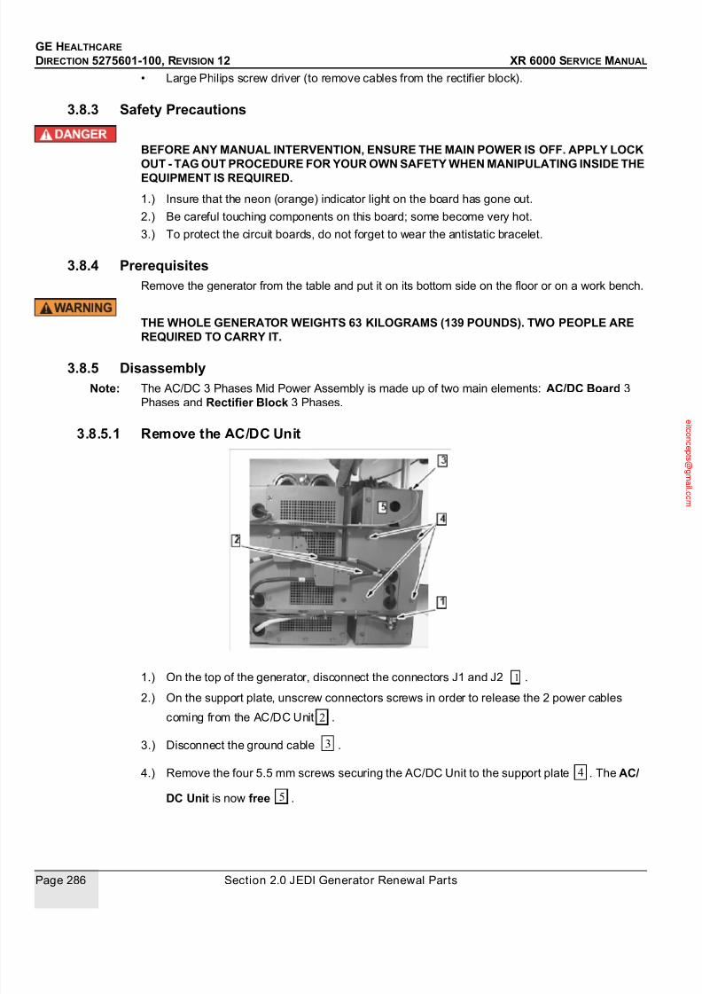
7/24/2019 GE XR6000 X-Ray - Service Manual
http://slidepdf.com/reader/full/ge-xr6000-x-ray-service-manual 286/421
GE HEALTHCARE
DIRECTION 5275601-100, REVISION 12 XR 6000 SERVICE MANUAL
Page 286 Section 2.0 JEDI Generator Renewal Parts
• Large Philips screw driver (to remove cables from the rectifier block).
3.8.3 Safety Precautions
BEFORE ANY MANUAL INTERVENTION, ENSURE THE MAIN POWER IS OFF. APPLY LOCKOUT - TAG OUT PROCEDURE FOR YOUR OWN SAFETY WHEN MANIPULATING INSIDE THE
EQUIPMENT IS REQUIRED.
1.) Insure that the neon (orange) indicator light on the board has gone out.
2.) Be careful touching components on this board; some become very hot.
3.) To protect the circuit boards, do not forget to wear the antistatic bracelet.
3.8.4 PrerequisitesRemove the generator from the table and put it on its bottom side on the floor or on a work bench.
THE WHOLE GENERATOR WEIGHTS 63 KILOGRAMS (139 POUNDS). TWO PEOPLE AREREQUIRED TO CARRY IT.
3.8.5 DisassemblyNote: The AC/DC 3 Phases Mid Power Assembly is made up of two main elements: AC/DC Board 3
Phases and Rectifier Block 3 Phases.
3.8.5.1 Remove the AC/DC Unit
1.) On the top of the generator, disconnect the connectors J1 and J2 .
2.) On the support plate, unscrew connectors screws in order to release the 2 power cables
coming from the AC/DC Unit .
3.) Disconnect the ground cable .
4.) Remove the four 5.5 mm screws securing the AC/DC Unit to the support plate . The AC/
DC Unit is now free .
1
2
3
4
5

7/24/2019 GE XR6000 X-Ray - Service Manual
http://slidepdf.com/reader/full/ge-xr6000-x-ray-service-manual 287/421
GE HEALTHCARE
DIRECTION 5275601-100, REVISION 12 XR 6000 SERVICE MANUAL
Chapter 8 - Renewal Parts Page 287
3.8.5.2 Remove the AC/DC Board
1.) Remove fourteen 5.5 mm hex head screws which retain the cover. Remove that one.
2.) Remove the two DC cables fastened with 10 mm nuts on the board .
3.) Remove two screws retaining the AC/DC board to the rectifier block .
4.) Remove seven 5.5 mm hex head screws and lift out the AC/DC Board .
3.8.5.3 Remove the Rectifier Block
1.) The Rectifier Block appears after removing the EMC Board (refer to 3.7 EMC Board 3
Phases) and the AC/DC Board.
2.) With the Allen key 3 mm, unscrew the 2 screws holding the rectifier to the chassis and
remove the block.
3.8.6 Reassembly
1.) Reverse the disassembly procedure to reinstall the AC/DC 3 PH Mid Power Assembly and the
1
2
3 4
1
2
7/24/2019 GE XR6000 X-Ray - Service Manual
http://slidepdf.com/reader/full/ge-xr6000-x-ray-service-manual 288/421
GE HEALTHCARE
DIRECTION 5275601-100, REVISION 12 XR 6000 SERVICE MANUAL
Page 288 Section 2.0 JEDI Generator Renewal Parts
EMC Board.
2.) Tighten the 10 mm cable retaining nuts to 3 N.m (30 kg.cm), and the 5.5 mm hex head screws
to 1.5 to 2 N.m (15 to 20 kg.cm).
Ensure cable terminals are repositioned as noticed before.
Verify that the + and - DC Bus cables are not reversed to prevent damage to the Inverter
(Refer to section Disassembly .
The Rectifier Block has to be placed with the two poles in regard of the AC/DC Board
(Refer to section Disassembly .
Be careful to preserve the special grease that is spread between the Rectifier Block andthe chassis. This grease, called: Conductive Surface Compound, provides both thermaland electrical conductivity that is important in reducing failure of the rectifier.
3.) Remount the generator inside the table.
3.8.7 VerifyReapply power and verify that the system functions correctly.
3.9 Inverter Coil Mid Power Assembly
3.9.1 SuppliesNone.
3.9.2 Tools• 5.5 mm nut driver or socket wrench with ratchet.
• 3 mm Allen wrench.
• 13 mm socket with ratchet.
3.9.3 Safety Precautions
BEFORE ANY MANUAL INTERVENTION, ENSURE THE MAIN POWER IS OFF. APPLY LOCKOUT - TAG OUT PROCEDURE FOR YOUR OWN SAFETY WHEN MANIPULATING INSIDE THEEQUIPMENT IS REQUIRED.
To protect the circuit boards, do not forget to wear the antistatic bracelet.
3.9.4 PrerequisitesRemove the generator from the table and put it on its bottom side on the floor or on a work bench.
THE WHOLE GENERATOR WEIGHTS 63 KILOGRAMS (139 POUNDS). TWO PEOPLE AREREQUIRED TO CARRY IT.
3.9.5 Personnel1 person.
1
1

7/24/2019 GE XR6000 X-Ray - Service Manual
http://slidepdf.com/reader/full/ge-xr6000-x-ray-service-manual 289/421
GE HEALTHCARE
DIRECTION 5275601-100, REVISION 12 XR 6000 SERVICE MANUAL
Chapter 8 - Renewal Parts Page 289
3.9.6 Time2 hours.
3.9.7 Disassembly
RESPECT THE CAUTION RELATING TO DANGEROUS VOLTAGE.
3.9.7.1 Remove the Auxiliary Unit and the Interface UnitRemove these Units as described in Disassembly / Reassembly procedure for 3.4 Inverter Mid-
Power Assembly.
3.9.7.2 Remove the AC/DC Unit and the support plateRemove the AC/DC Unit and the support plate as described in 3.4 Inverter Mid-Power Assembly.
THE POWER UNIT IS NOW FREE BUT IT WEIGHTS 30 KILOGRAMS (66 POUNDS). DO NOTTRY TO LIFT IT WITHOUT ASSISTANCE.
3.9.7.3 Remove the Inverter Coil Mid Power Assembly
1.) On the Power Unit, remove the 5.5 mm hex head screws which secure the L-shaped EMC
cover panel ; remove this one.
2.) With a 10 mm socket wrench with ratchet , remove the three hex head screws securing
A
1
2
3
1
2
3 4

7/24/2019 GE XR6000 X-Ray - Service Manual
http://slidepdf.com/reader/full/ge-xr6000-x-ray-service-manual 290/421
GE HEALTHCARE
DIRECTION 5275601-100, REVISION 12 XR 6000 SERVICE MANUAL
Page 290 Section 2.0 JEDI Generator Renewal Parts
the cables Q100C, Q100E and Q200C on the Inverter Mid Power Assembly.
3.) Remove the 10 mm screw on the left current transformer Ti1/40 pass through, top of the
Capacitor assembly. Retain the washers and release the cable.4.) Disconnect the two cables linking coils to capacitors at right and left Use a socket wrench
to remove screws.
5.) On each side , remove one 5.5 mm screw holding the coils support.
6.) Remove the Inverter Coil assembly .
3.9.8 Reassembly
1.) Present the new Inverter Coil assembly and mount one 5.5 mm hex head screw on each side
of the frame to hold the Coil assembly (refer to 3.9 Inverter Coil Mid Power Assembly
removed .
Tighten to torque between 1.5 to 2 N.m (15 to 20 kg.cm)
2.) Remount all cables that were removed.
a.) Remount the three Coil cables on the Inverter Mid Power Assembly (IGBTS) with three
5
6
7 7
6
5
6
7
8
8
7

7/24/2019 GE XR6000 X-Ray - Service Manual
http://slidepdf.com/reader/full/ge-xr6000-x-ray-service-manual 291/421
GE HEALTHCARE
DIRECTION 5275601-100, REVISION 12 XR 6000 SERVICE MANUAL
Chapter 8 - Renewal Parts Page 291
screws . There is a locking washer between the screws and the cable.
Tighten firmly to torque 3 N.m (30 kg.cm).
RESPECT THE ORIENTATION OF THE CABLES TO THE IGBTS CONNECTIONS TOAVOID CABLE CONTACT WITH TOP COVER.
b.) With the 10 mm screw, with flat and lock washer, remount the remaining cable from the
right coil (of the Coil assembly) onto the upper left current transformer Ti1/40 pass
through (refer to section Disassembly .
Tighten firmly to torque 3 N.m (30 kg.cm).
c.) Using a socket wrench, connect the two cables linking coils to capacitors at right and left
(refer to section Disassembly .
Tighten to torque between 1.5 to 2 N.m (15 to 20 kg.cm).
3.) Refer to Disassembly / Reassembly procedure for 3.4 Inverter Mid-Power Assembly.
1
2 5
6

7/24/2019 GE XR6000 X-Ray - Service Manual
http://slidepdf.com/reader/full/ge-xr6000-x-ray-service-manual 292/421
GE HEALTHCARE
DIRECTION 5275601-100, REVISION 12 XR 6000 SERVICE MANUAL
Page 292 Section 2.0 JEDI Generator Renewal Parts
3.9.9 VerifyIt is recommended to perform the “No load HV“ diagnostics test. “INVERTER GATE” and
“INVERTER in Short Circuit ” diagnostics are not pre-requested.
Verify correct operation on the whole application range.
3.10 Capacitor Inverter Assembly
3.10.1 SuppliesNone.
3.10.2 Tools• 5.5 mm nut driver or socket wrench with ratchet.
• 10 mm allen wrench.
• 13 mm socket with ratchet.
3.10.3 Safety Precautions
BEFORE ANY MANUAL INTERVENTION, ENSURE THE MAIN POWER IS OFF. APPLY LOCKOUT - TAG OUT PROCEDURE FOR YOUR OWN SAFETY WHEN MANIPULATING INSIDE THEEQUIPMENT IS REQUIRED.To protect the circuit boards, do not forget to wear the antistatic bracelet.
ENSURE THERE IS NO VOLTAGE ON THE DC BUS CABLE.
3.10.4 PrerequisitesRemove the generator from the table and put it on its bottom side on the floor or on a work bench.
THE WHOLE GENERATOR WEIGHTS 63 KILOGRAMS (139 POUNDS). TWO PEOPLE AREREQUIRED TO CARRY IT.
3.10.5 Personnel1 person.
3.10.6 Time3 hours.
3.10.7 Disassembly
RESPECT THE CAUTION RELATING TO DANGEROUS VOLTAGE.
3.10.7.1 Remove the Auxiliary Unit and the Interface UnitRemove these Units as described in 3.4 Inverter Mid-Power Assembly.
3.10.7.2 Remove the AC/DC Unit and the Support Plate
Remove the AC/DC Unit and the support plate together as described in 3.4 Inverter Mid-Power
Assembly.
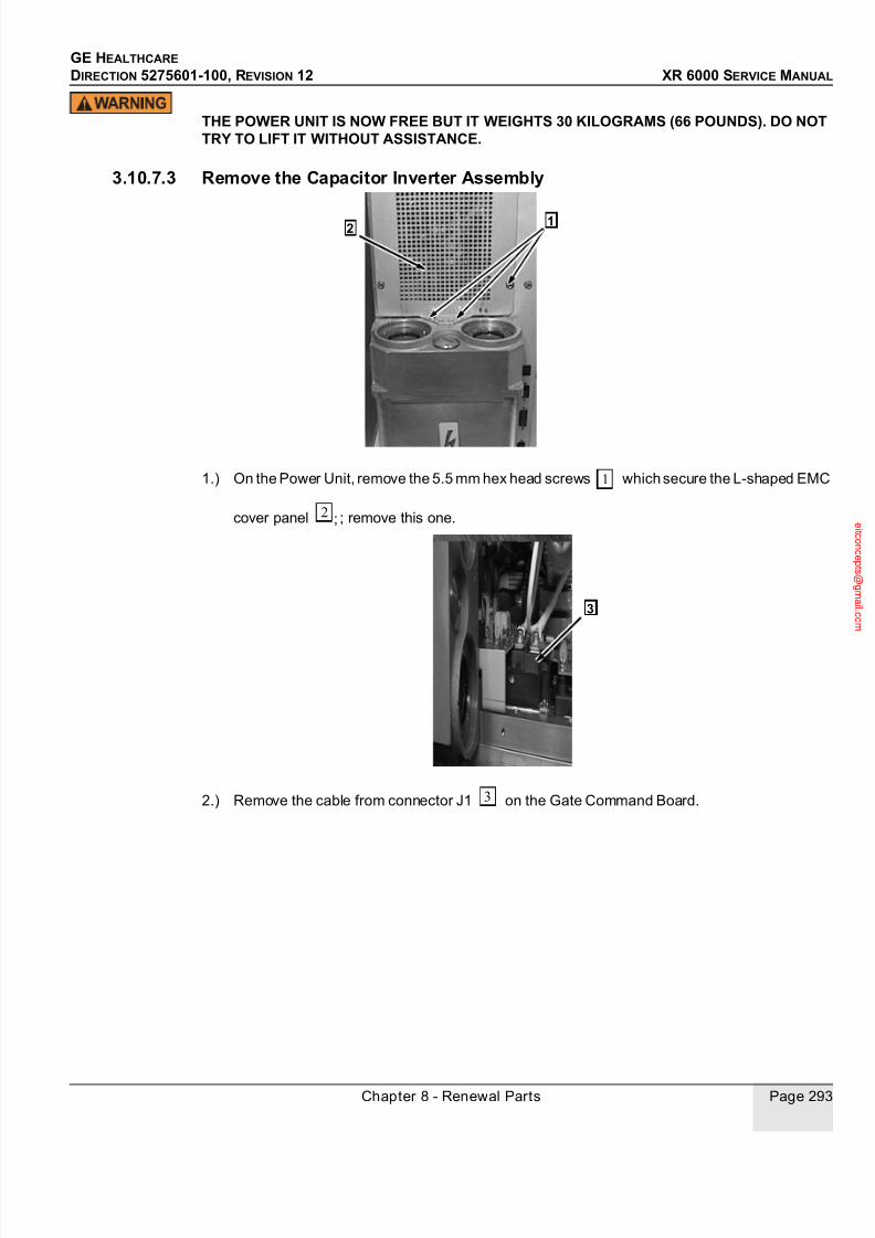
7/24/2019 GE XR6000 X-Ray - Service Manual
http://slidepdf.com/reader/full/ge-xr6000-x-ray-service-manual 293/421
GE HEALTHCARE
DIRECTION 5275601-100, REVISION 12 XR 6000 SERVICE MANUAL
Chapter 8 - Renewal Parts Page 293
THE POWER UNIT IS NOW FREE BUT IT WEIGHTS 30 KILOGRAMS (66 POUNDS). DO NOTTRY TO LIFT IT WITHOUT ASSISTANCE.
3.10.7.3 Remove the Capacitor Inverter Assembly
1.) On the Power Unit, remove the 5.5 mm hex head screws which secure the L-shaped EMC
cover panel ; remove this one.
2.) Remove the cable from connector J1 on the Gate Command Board.
12
1
2 ;
3
3
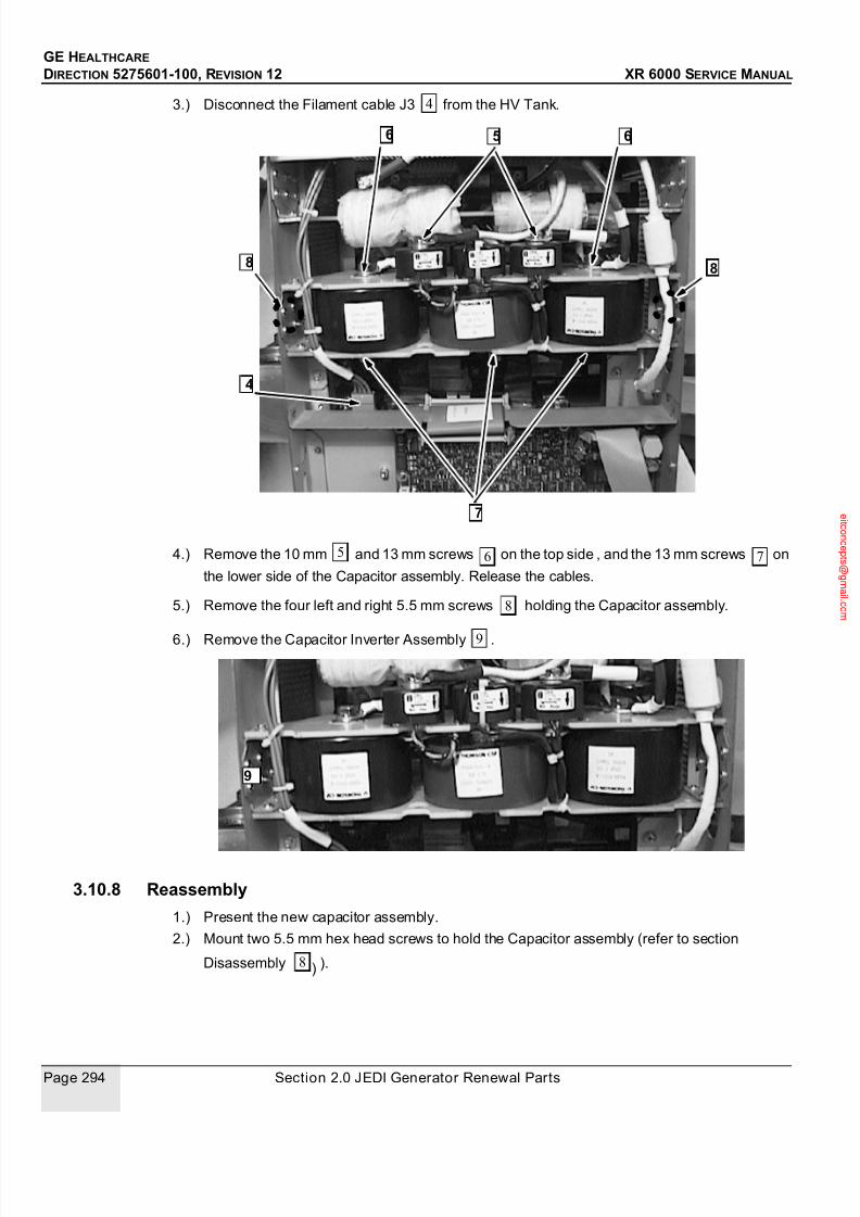
7/24/2019 GE XR6000 X-Ray - Service Manual
http://slidepdf.com/reader/full/ge-xr6000-x-ray-service-manual 294/421
GE HEALTHCARE
DIRECTION 5275601-100, REVISION 12 XR 6000 SERVICE MANUAL
Page 294 Section 2.0 JEDI Generator Renewal Parts
3.) Disconnect the Filament cable J3 from the HV Tank.
4.) Remove the 10 mm and 13 mm screws on the top side , and the 13 mm screws on
the lower side of the Capacitor assembly. Release the cables.
5.) Remove the four left and right 5.5 mm screws holding the Capacitor assembly.
6.) Remove the Capacitor Inverter Assembly .
3.10.8 Reassembly
1.) Present the new capacitor assembly.
2.) Mount two 5.5 mm hex head screws to hold the Capacitor assembly (refer to section
Disassembly ).
4
4
5 6
7
8
6
8
5 6 7
8
9
9
8 )

7/24/2019 GE XR6000 X-Ray - Service Manual
http://slidepdf.com/reader/full/ge-xr6000-x-ray-service-manual 295/421
GE HEALTHCARE
DIRECTION 5275601-100, REVISION 12 XR 6000 SERVICE MANUAL
Chapter 8 - Renewal Parts Page 295
3.) Reconnect the cable J1 on the Gate Command Board (refer to section Disassembly ).
4.) Attach the shorter cable (parallel coil) on the upper right current transformer (Ti1/100)
pass through with a 10 mm screw and its washers (refer to section Disassembly .
Tighten to torque 3 N.m (30 kg.cm).
5.) Remount the DC+ cable and the corresponding serial coil cable together on the upper leftside of the capacitor assembly with a 13 mm screw and its washers (refer to section
Disassembly . Tighten to torque 8 N.m (80 kg.cm).
6.) Remount the DC- cable and the corresponding serial coil cable together on the upperright side of the capacitor assembly with a 13 mm screw and its washers (refer to section
Disassembly . Tighten to torque 8 N.m (80 kg.cm).
7.) Remount the remaining serial coil cable to the upper left current transformer (Ti1/40) pass
through with a 10 mm screw and its washers (refer to section Disassembly . Tighten
to torque 3 N.m (30 kg.cm).8.) Run the ”INVERTER IN SHORT CIRCUIT” diagnostic:
HV TANK PRIMARY CABLES ARE DISCONNECTED AND ISOLATED.
Note: Connect the short circuit cable (included in the first aid kit) between the left capacitor and the
central capacitor (see picture in ”Inverter In Short Circuit diagnostics”).
a.) Tighten one extremity of the short circuit on the left capacitor with a 13 mm screw and
its washers. Tighten to torque 8 N.m (80 kg.cm).
b.) Mount the longer wire (Parallel Coil) and the other extremity of the short circuit on the
central capacitor (C3UF) with a 13 mm screw and its washers. Tighten to torque 8 N.m
(80 kg.cm),
3
1 5
6
6
1 5

7/24/2019 GE XR6000 X-Ray - Service Manual
http://slidepdf.com/reader/full/ge-xr6000-x-ray-service-manual 296/421
GE HEALTHCARE
DIRECTION 5275601-100, REVISION 12 XR 6000 SERVICE MANUAL
Page 296 Section 2.0 JEDI Generator Renewal Parts
Use the illustration below to check the connections are right:
c.) Reassemble the Power Unit with AC/DC Unit, Interface Unit and Auxiliary Unit (refer to
3.4 Inverter Mid-Power Assembly).
d.) Run “inverter short circuit diagnostics”.
9.) After ”INVERTER SHORT CIRCUIT” diagnostics, disassemble the Auxiliary Unit and the
Interface Unit (see section Disassembly). Remove the short circuit cable.10.) On the central capacitor (C3UF), attach together the two flat wires of the primary coils of the
HV transformer that have a white ring and the longer wire of Parallel Coil with a 13 mm
screw and its washers. Tighten to torque 8 N.m (80 kg.cm).
11.) Mount the two remaining flat cables from the HV Tank with 13 mm screws and their
+ -
C
E E
C
Capa Assembly
Coil Assembly
Inverter Assembly
Q100C Q200C
Q100E
+ DC - DC Ti1/40 Ti1/100
Parallel Coil
C3UF SHORT CIRCUIT
2
2
3 3
3

7/24/2019 GE XR6000 X-Ray - Service Manual
http://slidepdf.com/reader/full/ge-xr6000-x-ray-service-manual 297/421
GE HEALTHCARE
DIRECTION 5275601-100, REVISION 12 XR 6000 SERVICE MANUAL
Chapter 8 - Renewal Parts Page 297
washers underneath the capacitor assembly, one on the left side, one on the right side.
12.) Reconnect the Filament cable J3 on the HV Tank (refer to section Disassembly .
13.) Mount the two last remaining 5.5 mm hex head screws on the left and right side of the frame
(refer to section Disassembly).
Tighten to torque 1.5 to 2 N.m (15 to 20 kg.cm).
14.) Reassemble the Power Unit. Mount it with the AC/DC Unit, the Interface Unit and the AuxiliaryUnit on the support plate (Refer to 3.4 Inverter Mid-Power Assembly).
3.10.9 VerifyIt is recommended to perform the “No load HV“ diagnostics test. Verify correct operation on the
whole application range.
3.11 LV Power Supply 3 Phase Board
3.11.1 SuppliesNone.
3.11.2 Tools5.5 mm hex nut driver or socket wrench with ratchet.
3.11.3 Safety Precautions
BEFORE ANY MANUAL INTERVENTION, ENSURE THE MAIN POWER IS OFF. APPLY LOCKOUT - TAG OUT PROCEDURE FOR YOUR OWN SAFETY WHEN MANIPULATING INSIDE THEEQUIPMENT IS REQUIRED.
1.) Insure that the Neon N1 (orange) indicator light on the LVPS Board has gone out.
2.) Be careful touching components on the LVPS Board. Some become very hot.
To protect the circuit boards, do not forget to wear the antistatic bracelet.
3.11.4 PrerequisitesRemove the generator from the table and put it on its bottom side on the floor or on a work bench.
THE WHOLE GENERATOR WEIGHTS 63 KILOGRAMS (139 POUNDS). TWO PEOPLE AREREQUIRED TO CARRY IT.
3.11.5 Personnel1 person.
3.11.6 Time15 minutes.
4

7/24/2019 GE XR6000 X-Ray - Service Manual
http://slidepdf.com/reader/full/ge-xr6000-x-ray-service-manual 298/421
GE HEALTHCARE
DIRECTION 5275601-100, REVISION 12 XR 6000 SERVICE MANUAL
Page 298 Section 2.0 JEDI Generator Renewal Parts
3.11.7 Disassembly
3.11.7.1 Remove the Auxiliary Unit
1.) Disconnect the connectors J2 and J3 and the ground cable on the top of the generator .
2.) Remove four 5.5 mm hex head securing screws olding the Auxiliary Unit on the support
plate .
3.) Disconnect the flat ribbon cable without tearing, between the Auxiliary Unit and the
Interface Unit .
4.) Remove the Auxiliary Unit.
1
2 4
5
3 4
6
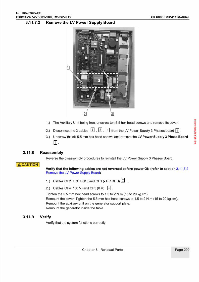
7/24/2019 GE XR6000 X-Ray - Service Manual
http://slidepdf.com/reader/full/ge-xr6000-x-ray-service-manual 299/421
GE HEALTHCARE
DIRECTION 5275601-100, REVISION 12 XR 6000 SERVICE MANUAL
Chapter 8 - Renewal Parts Page 299
3.11.7.2 Remove the LV Power Supply Board
1.) The Auxiliary Unit being free, unscrew ten 5.5 hex head screws and remove its cover.
2.) Disconnect the 3 cables , , from the LV Power Supply 3 Phases board .
3.) Unscrew the six 5.5 mm hex head screws and remove the LV Power Supply 3 Phase Board
.
3.11.8 ReassemblyReverse the disassembly procedures to reinstall the LV Power Supply 3 Phases Board.
Verify that the following cables are not reversed before power ON (refer to section 3.11.7.2
Remove the LV Power Supply Board:
1.) Cables CF2 (+DC BUS) and CF1 (- DC BUS) .
2.) Cables CF4 (160 V) and CF3 (0 V) .
Tighten the 5.5 mm hex head screws to 1.5 to 2 N.m (15 to 20 kg.cm).
Remount the cover. Tighten the 5.5 mm hex head screws to 1.5 to 2 N.m (15 to 20 kg.cm).
Remount the auxiliary unit on the generator support plate.
Remount the generator inside the table.
3.11.9 VerifyVerify that the system functions correctly.
1 2 3 4
4
2
3

7/24/2019 GE XR6000 X-Ray - Service Manual
http://slidepdf.com/reader/full/ge-xr6000-x-ray-service-manual 300/421
GE HEALTHCARE
DIRECTION 5275601-100, REVISION 12 XR 6000 SERVICE MANUAL
Page 300 Section 2.0 JEDI Generator Renewal Parts
3.12 Filament Board 1 INV
3.12.1 SuppliesNone.
3.12.2 Tools5.5 mm hex nut driver or socket wrench with ratchet.
3.12.3 Safety Precautions
BEFORE ANY MANUAL INTERVENTION, ENSURE THE MAIN POWER IS OFF. APPLY LOCKOUT - TAG OUT PROCEDURE FOR YOUR OWN SAFETY WHEN MANIPULATING INSIDE THEEQUIPMENT IS REQUIRED.
1.) Insure that the Neon DS3 (green) indicator light on the Filament Board has gone out.
2.) Be careful touching components on the Filament Board . Some become very hot.
To protect the circuit boards, do not forget to wear the antistatic bracelet.
3.12.4 PrerequisitesRemove the generator from the table and put it on its bottom side on the floor or on a work bench.
THE WHOLE GENERATOR WEIGHTS 63 KILOGRAMS (139 POUNDS). TWO PEOPLE AREREQUIRED TO CARRY IT.
3.12.5 Personnel1 person.
3.12.6 Time15 minutes.

7/24/2019 GE XR6000 X-Ray - Service Manual
http://slidepdf.com/reader/full/ge-xr6000-x-ray-service-manual 301/421
GE HEALTHCARE
DIRECTION 5275601-100, REVISION 12 XR 6000 SERVICE MANUAL
Chapter 8 - Renewal Parts Page 301
3.12.7 Disassembly
3.12.7.1 Remove the Auxiliary Unit
1.) Disconnect the connectors J2 and J3 and the ground cable on the top of the generator .
2.) Remove four 5.5 mm hex head securing screws holding the Auxiliary Unit on the
support plate .
3.) Disconnect the flat ribbon cable , without tearing, between the Auxiliary Unit and the
Interface Unit .
4.) Remove the Auxiliary Unit.
1
2 4
5
3 4
6

7/24/2019 GE XR6000 X-Ray - Service Manual
http://slidepdf.com/reader/full/ge-xr6000-x-ray-service-manual 302/421
GE HEALTHCARE
DIRECTION 5275601-100, REVISION 12 XR 6000 SERVICE MANUAL
Page 302 Section 2.0 JEDI Generator Renewal Parts
3.12.7.2 Remove the Filament Board
1.) The Auxiliary Unit being free, unscrew ten 5.5 mm hex head screws and remove its cover.
2.) Disconnect the ribbon cable between the Filament Board and the LVPS Board
. Disconnect and the connector J2 .
3.) Unscrew the six 5.5 mm hex head screws and remove the Filament Board 1 INV .
3.12.8 ReassemblyReverse the disassembly procedures to reinstall the Filament Board 1 INV.
Verify that cables CF4 (160 V) and CF3 (0 V) are not reversed before power ON (refer tosection 3.12.7.2 Remove the Filament Board).
Tighten the 5.5 mm hex head screws to 1.5 to 2 N.m (15 to 20 kg.cm).
Remount the cover. Tighten the 5.5 mm hex head screws to 1.5 to 2 N.m (15 to 20 kg.cm).
Remount the auxiliary unit on the generator support plate.
Remount the generator inside the table.
3.12.9 VerifyVerify that the system functions correctly.
Run Heater Function Diagnostics.
3.13 Rotor Board High Speed
3.13.1 SuppliesNone.
1 4 5
2 3
4
2

7/24/2019 GE XR6000 X-Ray - Service Manual
http://slidepdf.com/reader/full/ge-xr6000-x-ray-service-manual 303/421
GE HEALTHCARE
DIRECTION 5275601-100, REVISION 12 XR 6000 SERVICE MANUAL
Chapter 8 - Renewal Parts Page 303
3.13.1.1 Tools5.5 mm hex nut driver or socket wrench with ratchet.
3.13.2 Safety Precautions
BEFORE ANY MANUAL INTERVENTION, ENSURE THE MAIN POWER IS OFF. APPLY LOCKOUT - TAG OUT PROCEDURE FOR YOUR OWN SAFETY WHEN MANIPULATING INSIDE THEEQUIPMENT IS REQUIRED.
1.) Insure that the Neon DS7 (orange) indicator light on the Rotor Board has gone out.
2.) Be careful touching components on the Rotor Board. Some become very hot.
To protect the circuit boards, do not forget to wear the antistatic bracelet.
3.13.3 PrerequisitesRemove the generator from the table and put it on its bottom side on the floor or on a work bench.
THE WHOLE GENERATOR WEIGHTS 63 KILOGRAMS (139 POUNDS). TWO PEOPLE AREREQUIRED TO CARRY IT.
3.13.4 Personnel1 person.
3.13.5 Time15 minutes.
3.13.6 Disassembly
3.13.6.1 Remove the Auxiliary Unit
1.) Disconnect the connectors J2 and J3 and the ground cable on the top of the generator .
2.) Remove four 5.5 mm hex head securing screws holding the Auxiliary Unit on the
support plate .
1
2 4
5

7/24/2019 GE XR6000 X-Ray - Service Manual
http://slidepdf.com/reader/full/ge-xr6000-x-ray-service-manual 304/421
GE HEALTHCARE
DIRECTION 5275601-100, REVISION 12 XR 6000 SERVICE MANUAL
Page 304 Section 2.0 JEDI Generator Renewal Parts
3.) Disconnect the flat ribbon cable , without tearing, between the Auxiliary Unit and the
Interface Unit .
4.) Remove the Auxiliary Unit.
3.13.6.2 Remove the Rotor Board
1.) The Auxiliary Unit being free, unscrew ten 5.5 mm hex head screws and remove its cover.
2.) Disconnect the ribbon cable between the Rotor Board High Speed and the LVPS
Board Disconnect cables CF1 and CF2 .
3.) Unscrew two 5.5 mm hex head screws that are in holes below the surface of the board
and that secure an IGBT.
4.) Unscrew the eight 5.5 mm hex head screws and remove the Rotor Board High Speed .
Be careful to preserve the special grease that is spread between the IGBT and a heat sinkunder the Rotation Board. This grease, called "Conductive Surface Compound", providesboth thermal and electrical conductivity that are important in reducing failure of the IGBT.
3.13.7 ReassemblyReverse the disassembly procedure to reinstall the Rotor Board High Speed.
Tighten the 5.5 mm hex head screws to 1.5 to 2 N.m (15 to 20 kg.cm).
Ensure that cables are correctly connected. Ensure that marks on the cables match themarks on the board.
Remount the cover. Tighten the 5.5 mm hex head screws to 1.5 to 2 N.m (15 to 20 kg.cm).
Remount the auxiliary unit on the generator support plate.
Remount the generator inside the table.
3 4
6
1 4
5 2
3
4

7/24/2019 GE XR6000 X-Ray - Service Manual
http://slidepdf.com/reader/full/ge-xr6000-x-ray-service-manual 305/421
GE HEALTHCARE
DIRECTION 5275601-100, REVISION 12 XR 6000 SERVICE MANUAL
Chapter 8 - Renewal Parts Page 305
3.13.8 VerifyVerify that the system functions correctly.
Run Heater Function Diagnostics.
3.14 AEC Board
3.14.1 SuppliesNone.
3.14.2 Tools5.5 mm nut driver or socket wrench with ratchet.
3.14.3 Safety Precautions
BEFORE ANY MANUAL INTERVENTION, ENSURE THE MAIN POWER IS OFF. APPLY LOCK
OUT - TAG OUT PROCEDURE FOR YOUR OWN SAFETY WHEN MANIPULATING INSIDE THEEQUIPMENT IS REQUIRED.To protect the circuit boards, do not forget to wear the antistatic bracelet.
3.14.4 PrerequisitesRemove the generator from the table and put it on its bottom side on the floor or on a work bench.
THE WHOLE GENERATOR WEIGHTS 63 KILOGRAMS (139 POUNDS). TWO PEOPLE AREREQUIRED TO CARRY IT.
3.14.5 Personnel
1 person.
3.14.6 Time10 minutes.

7/24/2019 GE XR6000 X-Ray - Service Manual
http://slidepdf.com/reader/full/ge-xr6000-x-ray-service-manual 306/421
GE HEALTHCARE
DIRECTION 5275601-100, REVISION 12 XR 6000 SERVICE MANUAL
Page 306 Section 2.0 JEDI Generator Renewal Parts
3.14.7 Disassembly
3.14.7.1 Remove the Auxiliary Unit
1.) Disconnect the connectors J2 and J3 and the ground cable on the top of the generator .
2.) Remove four 5.5 mm hex head securing screws holding the Auxiliary Unit on the
support plate .
3.) Disconnect the flat ribbon cable , without tearing, between the Auxiliary Unit and the
Interface Unit .
4.) Remove the Auxiliary Unit.
3.14.7.2 Remove the AEC Board
1.) After removing the Auxiliary Unit, the Interface Unit appears. Release the flat ribbon cable
1
2 4
5
3 4
6

7/24/2019 GE XR6000 X-Ray - Service Manual
http://slidepdf.com/reader/full/ge-xr6000-x-ray-service-manual 307/421
GE HEALTHCARE
DIRECTION 5275601-100, REVISION 12 XR 6000 SERVICE MANUAL
Chapter 8 - Renewal Parts Page 307
, making it sliding along the cover panel of the Interface Unit.
2.) Unscrew twelve 5.5 mm screws that retain the cover panel and remove this one .
3.) Disconnect the flat ribbon cable from J5 between the I/F Board RAD and the AEC
Board .
4.) Disconnect the connectors J2 and J1 and Test Points TP1 and TP2 on the AEC
Board.
5.) Remove the six 5.5 mm screws securing the AEC Board .
3.14.8 ReassemblyReverse the disassembly procedure to reassemble the unit. Tighten screws to torque between 1.5
and 2 N.m (15 to 20 kg.cm).
3.14.9 VerifyReapply power. Proceed to ”AEC diagnostics” to ensure correct operation.
1 2
2
3
4
5
6
7
8
3 7
8
4 5 6
8

7/24/2019 GE XR6000 X-Ray - Service Manual
http://slidepdf.com/reader/full/ge-xr6000-x-ray-service-manual 308/421
GE HEALTHCARE
DIRECTION 5275601-100, REVISION 12 XR 6000 SERVICE MANUAL
Page 308 Section 2.0 JEDI Generator Renewal Parts
This page is intentionally left blank.

7/24/2019 GE XR6000 X-Ray - Service Manual
http://slidepdf.com/reader/full/ge-xr6000-x-ray-service-manual 309/421
Chapter 9 - Service Tool Job Cards Page 309
GE HEALTHCARE
DIRECTION 5275601-100, REVISION 12 XR 6000 SERVICE MANUAL
Chapter 9 - Service Tool Job Cards
Section 1.0
Software Download / Upgrade
1.1 Supplies
None.
1.2 Tools
• JEDI service software (the software is a DOS application)
• Console R232 cable (5194292)
• Computer with floppy or CD drive
1.3 Safety Precautions
Not applicable.
1.4 Prerequisites
Basic knowledge of PC based computer laptop, DOS and usage of Microsoft WINDOWS.
1.5 Personnel1 person.
1.6 Time
15 minutes.
1.7 Procedure
1.7.1 Load Software File on Service Laptop
1.) To load the software on to the hard drive(windows 2000 or under):It can operate under DOS
or Windows;
2.) Power ON the computer, Under Windows, run the File Manager (Explorer);
3.) Create a new directory (e.g.: JEDITEST) under C:\;
4.) Insert the ”JEDI Software” floppy delivered with the equipment into the floppy drive;
5.) Copy all the files from the floppy to your hard drive.
1.7.2 Unzip software fileThe CD drive supplied with the equipment (or the upgrade kit) contains “Auto-zipped” files.

7/24/2019 GE XR6000 X-Ray - Service Manual
http://slidepdf.com/reader/full/ge-xr6000-x-ray-service-manual 310/421
GE HEALTHCARE
DIRECTION 5275601-100, REVISION 12 XR 6000 SERVICE MANUAL
Page 310 Section 1.0 Software Download / Upgrade
It is necessary to load those files on the hard disk drive and run them; they will unzip and create
other files that you will use.
• Double click on the JEDP424B.exe file, and verify that the new file is created.
1.7.3 Software download
1.) Connect console R232 cable Part No. 5194292 to console connecter J2;
2.) System power up;
3.) Press button together more than 5 seconds to enter the HUB model;
4.) Restart the computer in DOS mode (for software download or database backup, it is required
to run ASIAN.exe under DOS to avoid communication problem).
With the mouse, click on START, SHUTDOWN, RESTART COMPUTER UNDER DOS
MODE.
5.) Run the program:
Under DOS:
* Select Disk drive from where you want to run the program:
* C: [enter]
* key in: “ASIAN” [enter]
6.) From the laptop software main screen, type “F7: restore memory”.
7.) Type “appl.mx”, then enter (or C:\JEDI\appl.mx).Wait for the count to start. It may take 20 seconds before starting. The software code transfer
will take about 20 minutes. Download is complete when all the LEDs on kV Control board are
ON and laptop indicates download is complete.
Normally, the kV Control board will reset at the end of transfer and all the LEDs will scroll.
8.) Verify the software version is P3.2, behind “RAM” text (or P3.X in case of new software);

7/24/2019 GE XR6000 X-Ray - Service Manual
http://slidepdf.com/reader/full/ge-xr6000-x-ray-service-manual 311/421
Chapter 9 - Service Tool Job Cards Page 311
GE HEALTHCARE
DIRECTION 5275601-100, REVISION 12 XR 6000 SERVICE MANUAL
9.) Select menu 2 with the arrows, select LIST, and clear generator error log. (^H, then W);
10.) To exit program, press Q, or R to return then ESC, or ESC twice.
Section 2.0
Tube Replacement Software Procedure
2.1 Supplies
None.
2.2 Tools
• JEDI service software (the software is a DOS application)
• Console R232 cable (5194292)
• Computer with floppy or CD drive
2.3 Safety Precautions
Not applicable.
2.4 Prerequisites
Basic knowledge of PC based computer laptop, DOS and usage of Microsoft WINDOWS.Knowledge of Service Software (refer to Chapter 3 - - Configuraton & Calibration - 2.3 - Service
Software User Guide).
2.5 Personnel
1 person.
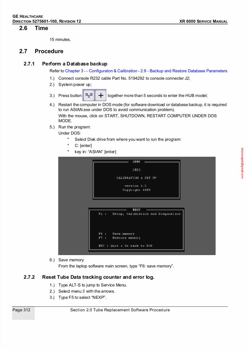
7/24/2019 GE XR6000 X-Ray - Service Manual
http://slidepdf.com/reader/full/ge-xr6000-x-ray-service-manual 312/421
GE HEALTHCARE
DIRECTION 5275601-100, REVISION 12 XR 6000 SERVICE MANUAL
Page 312 Section 2.0 Tube Replacement Software Procedure
2.6 Time
15 minutes.
2.7 Procedure
2.7.1 Perform a Database backupRefer to Chapter 3 - - Configuraton & Calibration - 2.9 - Backup and Restore Database Parameters
1.) Connect console R232 cable Part No. 5194292 to console connecter J2;
2.) System power up;
3.) Press button together more than 5 seconds to enter the HUB model;
4.) Restart the computer in DOS mode (for software download or database backup, it is required
to run ASIAN.exe under DOS to avoid communication problem).
With the mouse, click on START, SHUTDOWN, RESTART COMPUTER UNDER DOS
MODE.5.) Run the program:
Under DOS:
* Select Disk drive from where you want to run the program:
* C: [enter]
* key in: “ASIAN” [enter]
6.) Save memory
From the laptop software main screen, type “F6: save memory”.
2.7.2 Reset Tube Data tracking counter and error log.
1.) Type ALT-S to jump to Service Menu.
2.) Select menu 2 with the arrows.
3.) Type F5 to select “NEXP”.

7/24/2019 GE XR6000 X-Ray - Service Manual
http://slidepdf.com/reader/full/ge-xr6000-x-ray-service-manual 313/421
Chapter 9 - Service Tool Job Cards Page 313
GE HEALTHCARE
DIRECTION 5275601-100, REVISION 12 XR 6000 SERVICE MANUAL
Note: Before resetting all the memory, it is advised to record them on table 2.7.4 - Generator Counter
Reading Record, found at the end of this Job Card.
4.) Enter H, press W to confirm.
All the tube related Data will be erased; only Generator related Data will be kept.
The filament ageing parameter will be reset to default value.

7/24/2019 GE XR6000 X-Ray - Service Manual
http://slidepdf.com/reader/full/ge-xr6000-x-ray-service-manual 314/421
GE HEALTHCARE
DIRECTION 5275601-100, REVISION 12 XR 6000 SERVICE MANUAL
Page 314 Section 2.0 Tube Replacement Software Procedure
5.) Type Q to go back to main screen.
2.7.3 Verify new tube operation, clear error log
1.) Press F1 to jump to application screen.
2.) Run a dozen of exposures from low kv, mA, to high kV, mA in direct workstation.
3.) Verify correct operation of the system.
4.) Go in menu 2, LIST (F3); Clear the Error log.
5.) Exit from laptop service software.
6.) Run exposures from the Operating console.
7.) Take necessary steps to ship the replaced tube. Include filled out table with tube
information.
2.7.4 Generator Counter Reading Record
GENERATOR COUNTER READING RECORD
Date of reading: Date of putting into service:
Address of
installation:
Generator identification:
Serial number:
Software version:
Options: (AEC)
X-Ray system
description:
Counter name Tube data Explanation
NO WARMUP Number of skipped Warm-up (N/A on Tiger)

7/24/2019 GE XR6000 X-Ray - Service Manual
http://slidepdf.com/reader/full/ge-xr6000-x-ray-service-manual 315/421
Chapter 9 - Service Tool Job Cards Page 315
GE HEALTHCARE
DIRECTION 5275601-100, REVISION 12 XR 6000 SERVICE MANUAL
2.7.5 Tube Database DownloadThe service tool software can operate under Windows (Windows 2000 or lower version) or DOS.
1.) Use the RS232 Service Cable (5194292) to connect the console connector J2 with computer.
2.) Power up the computer, insert the CD (5212186). Under Windows, run the File Manager(Explorer).
3.) Create a new directory (e.g.: JEDITEST) under C:\.
4.) Copy all the files from the CD to your new directory.
5.) Double click the file "ASIAN.EXE" to run service tool software.
6.) System power up.
7.) On the application screen, press button together for more than 5 seconds to
enter the HUB mode.
8.) Press function key F7 to Load Software according to the tube installed.
- 50 kW tube: type E7843X File : E7843_R?.mx (? means the current revision)
9.) When the successful installation message display, press Esc button on the computer.
10.) Press the function key F1 into the Jedi application interface.
11.) Press Alt and S key together to enter service interface.
12.) Set Date&Time.
- Call Menu 2 using the arrows on the keyboard.
- Call DATE by pressing F7.
- Enter date (MM DD YYYY) via numeric keypad.
- Hit W to confirm.
- Hit F1.
RXGSF H Cumulated exposure time on small focus
RXGLF H Cumulated exposure time on large focus
RXSCOP H Cumulated exposure time in fluoro (N/A on RAD.)
ROTANOD H Cumulated Anode rotation time
NEXPSF Cumulated Number of exposure on small focus
NEXPLF Cumulated Number of exposure on large focus
N100%SF Cumulated Number of exposure on small focus at
100 % Power (N/A on Tiger)
N100%LF Cumulated Number of exposure on large focus (N/
A on Tiger)
NAMOR Cumulated Number of spits
KJSF E Cumulated dissipated power on Small focus
KJLF E Cumulated dissipated power on Large focus
TIME_ON H Total generator Power On time (Not erasable)
N_EXP_G H Total generator number of exposure (Not erasable)
7/24/2019 GE XR6000 X-Ray - Service Manual
http://slidepdf.com/reader/full/ge-xr6000-x-ray-service-manual 316/421
GE HEALTHCARE
DIRECTION 5275601-100, REVISION 12 XR 6000 SERVICE MANUAL
Page 316 Section 2.0 Tube Replacement Software Procedure
- Enter time (HH MM) via numeric keypad.
- Hit W to confirm.
13.) Checksums
Checksums must be validated at the end of the generator setup or whenever a parameter is
changed.
- Call Menu 5 using the arrows on the keyboard.
- Press function key F1.
- Press function key [F1] and [V] simultaneously.
- A buzzer will sound, which indicating that the sums have been checked and OK on display
screen.
14.) Press "R" key to return to the application mode.
15.) Press Esc key to exit the JEDI software.
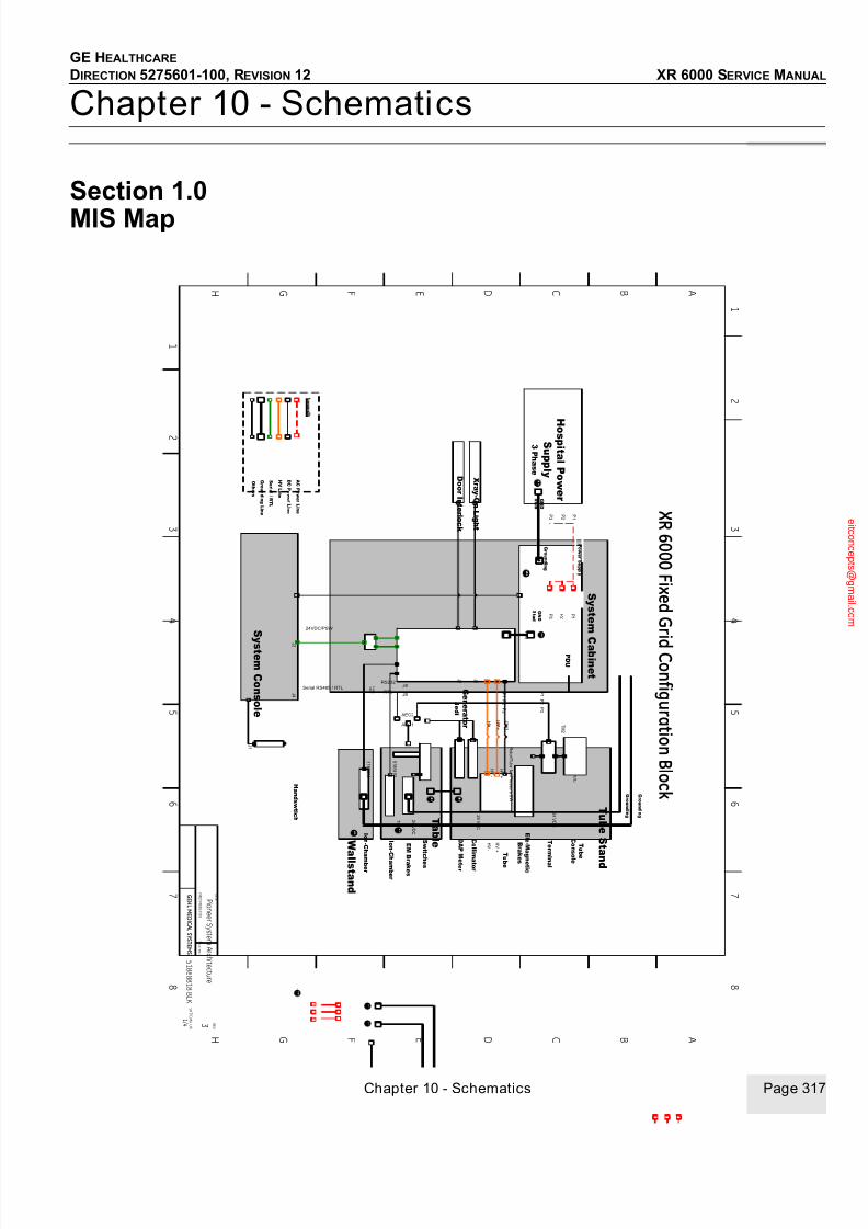
7/24/2019 GE XR6000 X-Ray - Service Manual
http://slidepdf.com/reader/full/ge-xr6000-x-ray-service-manual 317/421
GE HEALTHCARE
DIRECTION 5275601-100, REVISION 12 XR 6000 SERVICE MANUAL
Chapter 10 - Schematics Page 317
Chapter 10 - Schematics
Section 1.0
MIS Map
1
2
3
4
5
6
7
8
1
2
3
4
5
6
7
8
A B C D E F G H
A B C D E F G H
P i o n e e r
P i o n e e r S y s t e m A r c h i t e c t u r e
T I T L E
F I R S T M A D E F O R :
R E V
G E H L ME D I C A L S Y S T E M S
S H T / C O N T O N
5 1 8 8 8 8 1 8 B L K
1 / 4 3
X R 6 0 0 0 F i x e d G r
i d C o n f i g u r a t i o nB l o c k
S
y s t em
C on s ol e
S y s t em
C a b i n e t
T u b e S t an d
H o s pi t al P ow er
S u p pl y
3 P h a s e
Xr a y- OnL i gh t
D o or I n t er l o ck
Gr o un d i n g
P D U
H an d sw t i ch
G en er a t or
J e d i
Gr o un d i n g
T
u b e
I on- C
h am b er
R o t or / T
u b ef an
/ P r e
s s ur e
S W
H V +
H V -
Serial RS485 / RTL
2 4 V D
C
GND
S t u d
GND
S t u d
E l e- M a g
n e t i c
Br ak
e s
A CP ow er L i n e
Gr o un d i n gL i n e
24VDC/PSW
HVL i n e
O t h er s
D CP ow er L i n e
2 4 V D
C
P 1
P 2
P 3
I on- Ch a
m b er
AEC1
AEC2
W al l s t an d
P 3
P 3
T a b l e
Gr o un d i n g
E MBr ak e s
2 4 V D
C
J9 J 4
J 1
J 3
R S 4 8 5 /
R S 2 3 2
J8
RTL
RS232
S er i al / RT L
T u b e
C on s o
l e
2 4 V D
C
S wi t c
h e s
T M
3
T M2
T M1
P ow er S u p pl y
P 1
P 2
P 3
P 1 P 2
P 1 P 2
H V +
H V -
H V -
H V +
J 2
/ J 3
J 6
J 6
T er m
i n al
5 1
6 6 4
9 3
5 1
6 6 6 5 4
C ol l i m
a t or
DAP M
e t er
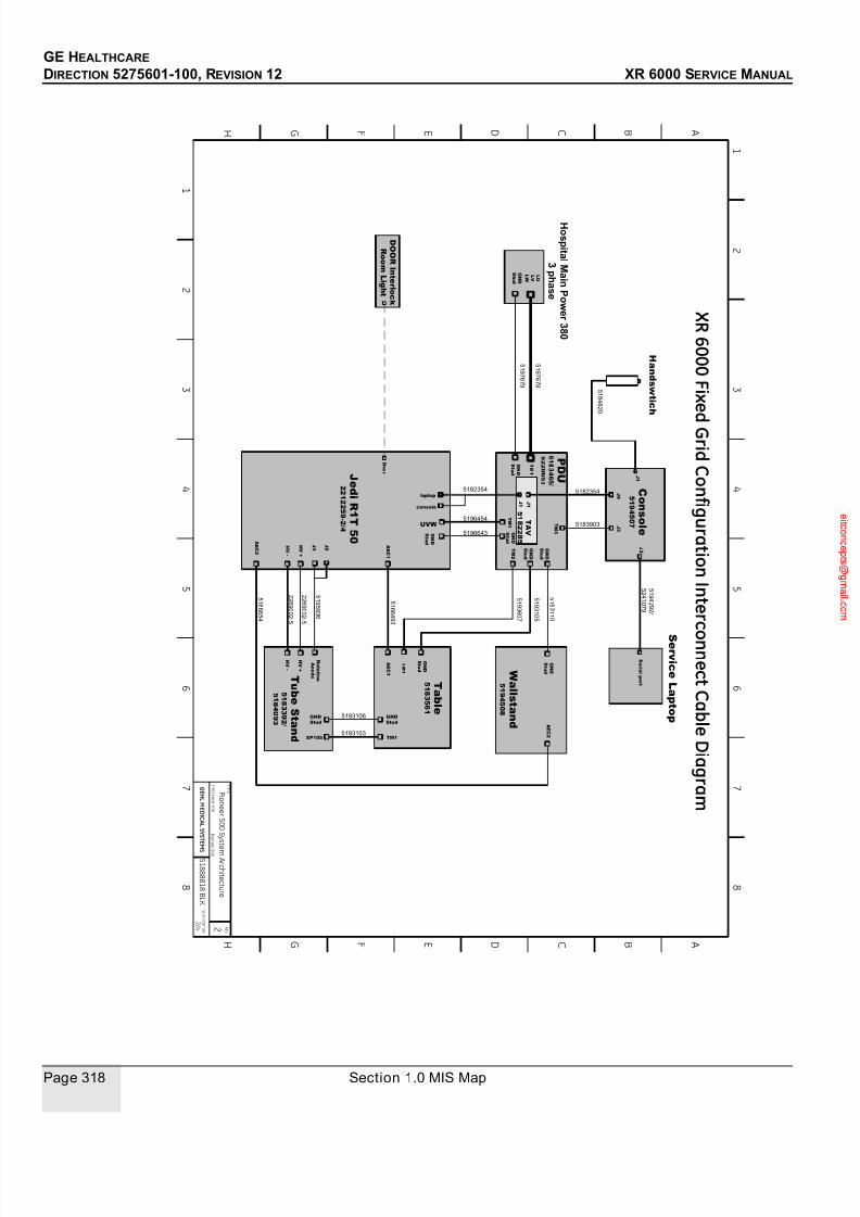
7/24/2019 GE XR6000 X-Ray - Service Manual
http://slidepdf.com/reader/full/ge-xr6000-x-ray-service-manual 318/421
GE HEALTHCARE
DIRECTION 5275601-100, REVISION 12 XR 6000 SERVICE MANUAL
Page 318 Section 1.0 MIS Map
1
2
3
4
5
6
7
8
1
2
3
4
5
6
7
8
A B C D E F G H
A B C D E F G H
P i o n e e r 5 0 0
P i o n e e r 5 0 0 S y s t e
m A r c h i t e c t u r e
T I T L E
F I R S T M A D E F O R :
R E V
G E H L ME D I C A L S Y S T E M
S
S H T / C O N T O N
5 1 8 8 8 8 1 8 B L K
2 / 4 2
X R 6 0 0 0 F i x e
d G r i d C o n f i g u r a t i o n I n t e r c
o n n e c t C a b l eD i a g r a m
C on s ol e
5 1 9 4 5 0 7
5182354
J e d i R1 T 5 0
2 2 1 2 2 5 9 - 2 / 4
5 1 9 5 9 3 6
2 2 6 9 0 0 2 - 5
HV-
5 1 6 6 4 9 3
J 1
5 1 9 3 1 0 5
AE C1
AE C2
W al l s t an d
5 1 9 4 5 0 8
T a b l e
5 1 8 3 5 6 1
5 1 9 3 6 0 7
console
J 4
5 1 9 3 1 1 0
5 1 6 6 6 5 4
laptop
5183903
J 2
TM 3
2 2 6 9 0 0 2 - 5
HV+
TM1
XP105
5193106
5193103TM1
5182354
PD U
5 1 8 3 4 6 5 /
5 2 2 0 6 5 3
J 1
GND
S t u d
TM1
GND
S t u d
T u b e S t an d
5 1 8 3 3 9 2 /
5 1 8 4 0 9 3
TM2
GND
S t u d
5196454 J 3
S er vi c eL a p t o p
S er i al p or t
GND
S t u d
GND
Stud
GND
Stud
5 1 9 4 2 9 2 /
5 2 4 1 0 7 9
H an d sw t i ch
5 1 8 4 6 2 0
UVW
H o s pi t al M ai nP ow er 3 8 0
3 ph a s e
5 1 9 7 6 7 8
HV+
HV-
J 2
J 3
R o t a t i on
An o d e
AE C1
AE C2
D O ORI n t er l o ck
R o om
L i gh t
D o or
TM1
J 1
J 1
TAV
5 1 8 2 2 8 5
GND
S t u d
GND
S t u d
5 1 9 7 6 7 9
L U
L V
L W
5196643 GND
S t u d
GND
S t u d

7/24/2019 GE XR6000 X-Ray - Service Manual
http://slidepdf.com/reader/full/ge-xr6000-x-ray-service-manual 319/421
GE HEALTHCARE
DIRECTION 5275601-100, REVISION 12 XR 6000 SERVICE MANUAL
Chapter 10 - Schematics Page 319
1
2
3
4
5
6
7
8
1
2
3
4
5
6
7
8
A B C DE F G H
A B C DE F G H
P i o n e e r
P
i o n e e r S y s t e m A r c h i t e c t u r e
T I T L E
F I R S T M
A DE F O R :
R E V
GE HL ME D I C A L S Y S T E M S
S H T / C O N T O N
5 1 8 8 8 8 1 8 B L K
3 / 4 3
X R 6 0 0 0
O s c i l l a t i n gB u c k y C o n f i g
u r a t i o nB l o c k
S y s t em
C on s ol e
S y s t em
C a bi n e t
T u b e S t an d
H o s pi t al P ow er
S u p pl y
3Ph a s e
Xr a y- OnLi gh t
D o or I n t er l o ck
Gr o un di n g
PD U
H an d sw t i ch
G en er a t or
J e di
Gr o un di n g
T u b e
I on- Ch am b er
R o t or / T
u b ef an
/ Pr e
s s ur e
SW
HV+
HV-
Serial RS485 / RTL
2 4 VD
C
GND
S t u d
GND
S t u d
El e-M a gn e t i c
Br ak e s
A CP ow er Li n e
Gr o un di n gLi n e
24VDC/PSW
HVLi n e
O t h er s
D CP ow er Li n e
C ol l i m a t or
2 4 VD
C
P1
P2
P 3
I on- Ch am b er
AEC1
AEC2
W al l s t an d
P 3
P 3
T a bl e
Gr o un di n g
EMBr ak e s
2 4 VD
C
J9 J 4
J 1
J 3
5 1
6 6 4
9 3
W al l - s
t an
d B
u ck
y C on
t r ol
R S4
8 5 /
R S2
3 2
J8
RTL
RS232
S er i al / RTL
T u b e
C on s ol e
2 4 VD
C
Swi t ch e s
T M
3
T M2
T M1
P ow er S u p pl y
P1
P2
P 3
P1 P2
P1 P2
HV+
HV-
HV-
HV+
J 2 / J 3
J 6
J 6
T er mi n al
B u ck y
B u ck y
WS Bucky
Table Bucky
T a b l eB
u ck
y C on
t r ol
5 1
6 6 6 5 4
J 4
2 4 VD
C
Swi t ch e s
T M1
EMBr ak e s
J 1
J 4
110 VAC
DAPM e t er

7/24/2019 GE XR6000 X-Ray - Service Manual
http://slidepdf.com/reader/full/ge-xr6000-x-ray-service-manual 320/421
GE HEALTHCARE
DIRECTION 5275601-100, REVISION 12 XR 6000 SERVICE MANUAL
Page 320 Section 1.0 MIS Map
1
2
3
4
5
6
7
8
1
2
3
4
5
6
7
8
A B C D E F G H
A B C D E F G H
P i o n e e r 5 0 0
P i o n e e r 5 0 0 S y s t e m A r c h i t e c t u r e
T I T L E
F I R S T M A D E F O R :
R E V
G
E HL ME D I C A L S Y S T E M S
S H T / C O N T O N
5 1 8 8 8 8 1 8 B L K
4 / 4 3
X R 6 0 0 0 O s c i l l a t i n gB u c k y C o n f i g u r a t i o n I n t e r c o n n e c t C a b l e
D i a g r a m C
on s ol e
5 1 9 4 5 0 7
5182354
J e d i R1 T 5 0
2 2 1 2 2 5 9 -2
5 1 9 5 9 3 6
2 2 6 9 0 0 2 - 5
HV-
5 1 6 6 4 9 3
J 1
5 1 9 3 1 0 5
AE C1
AE C2
W al l s t an d
5 3 1 6 7 7 3
T a b l e
5 3 1 6 7 7 2
5 1 9 3 6 0 7
console
J 4
5 1 9 3 1 1 0
5 1 6 6 6 5 4
laptop
5183903
J 2
TM 3
2 2 6 9 0 0 2 - 5
HV+
TM1
XP105
5193106
5193103TM1
5182354
PD U
5 2 2 0 6 5 3
J 1
GND
S t u d
TM1
GND
S t u d
T u b e S t an d
5 1 8 3 3 9 2
TM2
GND
S t u d
5196454 J 3
S er vi c eL a p t o p
S er i al p or t
GND
S t u d
GND
Stud
GND
Stud
5
1 9 4 2 9 2 /
5
2 4 1 0 7 9
H an d sw t i ch
5 1 8 4 6 2 0
UVW
H o s pi t al M ai nP ow er 3 8 0
3 ph a s e
5 1 9 7 6 7 8
HV+
HV-
J 2
J 3
R o t a t i on
An o d e
AE C1
AE C2
D O ORI n t er l o ck
R o om
L i gh t
D o or
TM1
J 1
J 1
TAV
5 1 8 2 2 8 5
GND
S t u d
GND
S t u d
5 1 9 7 6 7 9
L U
L V
L W
5196643 GND
S t u d
GND
S t u d
J 1
J 4 5313870
5 3 1 5 8
3 4
B u ck y
W S
B u ck y
B u ck y
T a b l e
B u ck y
5 3 1 3 8
6 9
5 3 1 5 8 6 4
TM1
J 4

7/24/2019 GE XR6000 X-Ray - Service Manual
http://slidepdf.com/reader/full/ge-xr6000-x-ray-service-manual 321/421
GE HEALTHCARE
DIRECTION 5275601-100, REVISION 12 XR 6000 SERVICE MANUAL
Chapter 10 - Schematics Page 321
1.1 Jedi 50 R 1T Cabling

7/24/2019 GE XR6000 X-Ray - Service Manual
http://slidepdf.com/reader/full/ge-xr6000-x-ray-service-manual 322/421
GE HEALTHCARE
DIRECTION 5275601-100, REVISION 12 XR 6000 SERVICE MANUAL
Page 322 Section 1.0 MIS Map
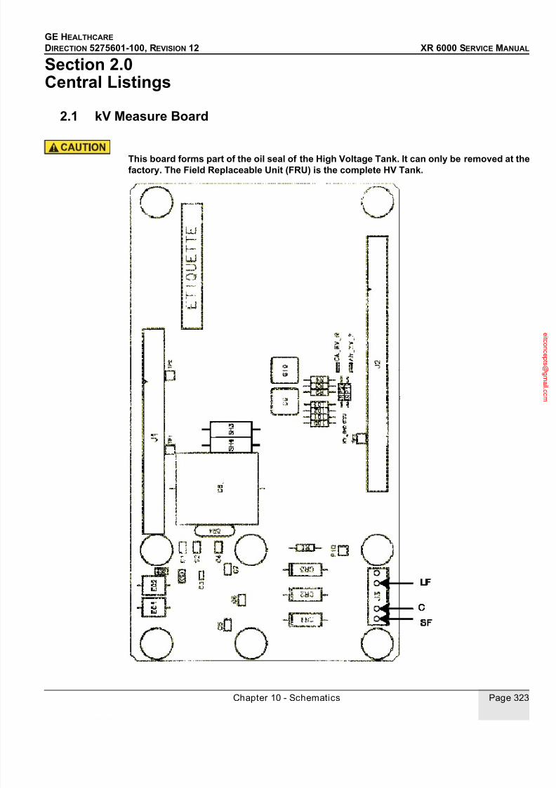
7/24/2019 GE XR6000 X-Ray - Service Manual
http://slidepdf.com/reader/full/ge-xr6000-x-ray-service-manual 323/421
GE HEALTHCARE
DIRECTION 5275601-100, REVISION 12 XR 6000 SERVICE MANUAL
Chapter 10 - Schematics Page 323
Section 2.0 Central Listings
2.1 kV Measure Board
This board forms part of the oil seal of the High Voltage Tank. It can only be removed at thefactory. The Field Replaceable Unit (FRU) is the complete HV Tank.

7/24/2019 GE XR6000 X-Ray - Service Manual
http://slidepdf.com/reader/full/ge-xr6000-x-ray-service-manual 324/421
GE HEALTHCARE
DIRECTION 5275601-100, REVISION 12 XR 6000 SERVICE MANUAL
Page 324 Section 2.0 Central Listings
2.2 Filament Board 1 Inv.
HIGH VOLTAGE: DO NOT GO INTO GENERATOR UNTIL INDICATOR DS3 GOES OUT.
RST - Red - Board beingreset or powered up
SF_LF - Yellow - SmallFocus / Large Focus
Relay Feedback
DS2 - Yellow - StatusLED
DS1 - Yellow - StatusLED
DS3 - Green - +160vDC present
DS4 - Yellow - InverterOutput Running
ON - Yellow - InverterCommand ON
160v LF Common
SF
0
160v
DC

7/24/2019 GE XR6000 X-Ray - Service Manual
http://slidepdf.com/reader/full/ge-xr6000-x-ray-service-manual 325/421
GE HEALTHCARE
DIRECTION 5275601-100, REVISION 12 XR 6000 SERVICE MANUAL
Chapter 10 - Schematics Page 325
2.3 Rotation Board High Speed
HIGH VOLTAGE: DO NOT GO INTO GENERATOR UNTIL INDICATOR DS6 AND DS7 (NEON-ORANGE) GO OUT.
DS6
CommonDC bus
Auxiliary
DC bus
Main
DC bus

7/24/2019 GE XR6000 X-Ray - Service Manual
http://slidepdf.com/reader/full/ge-xr6000-x-ray-service-manual 326/421
GE HEALTHCARE
DIRECTION 5275601-100, REVISION 12 XR 6000 SERVICE MANUAL
Page 326 Section 2.0 Central Listings
2.3.1 Indicators
2.3.2 J2 Wiring
INDICATOR COLOR INDICATES:
RESET RED BOARD BEING RESET OR POWERED UP
INV_ON YELLOW THE INVERTER IS RUNNING
DS1 GREEN PRESENCE OF +15 V SUPPLY
DS2 GREEN PRESENCE OF -15 V SUPPLY
DS3 GREEN PRESENCE OF +5 V SUPPLY
DS4-DS5 YELLOW BOARD STATUS
DS6 NEON (ORANGE) FAN VAC POWER SUPPLY PRESENT
DS7 NEON (ORANGE) DC BUS PRESENT
1 2 3 4 5 6 7 8 9 10 11 12 13 14 15 16
X-ray tube
Thermal safety
Fan, 115V ACLine input
Fan*, 115V ACLine output
115V
sense
* used in application with fan cooling
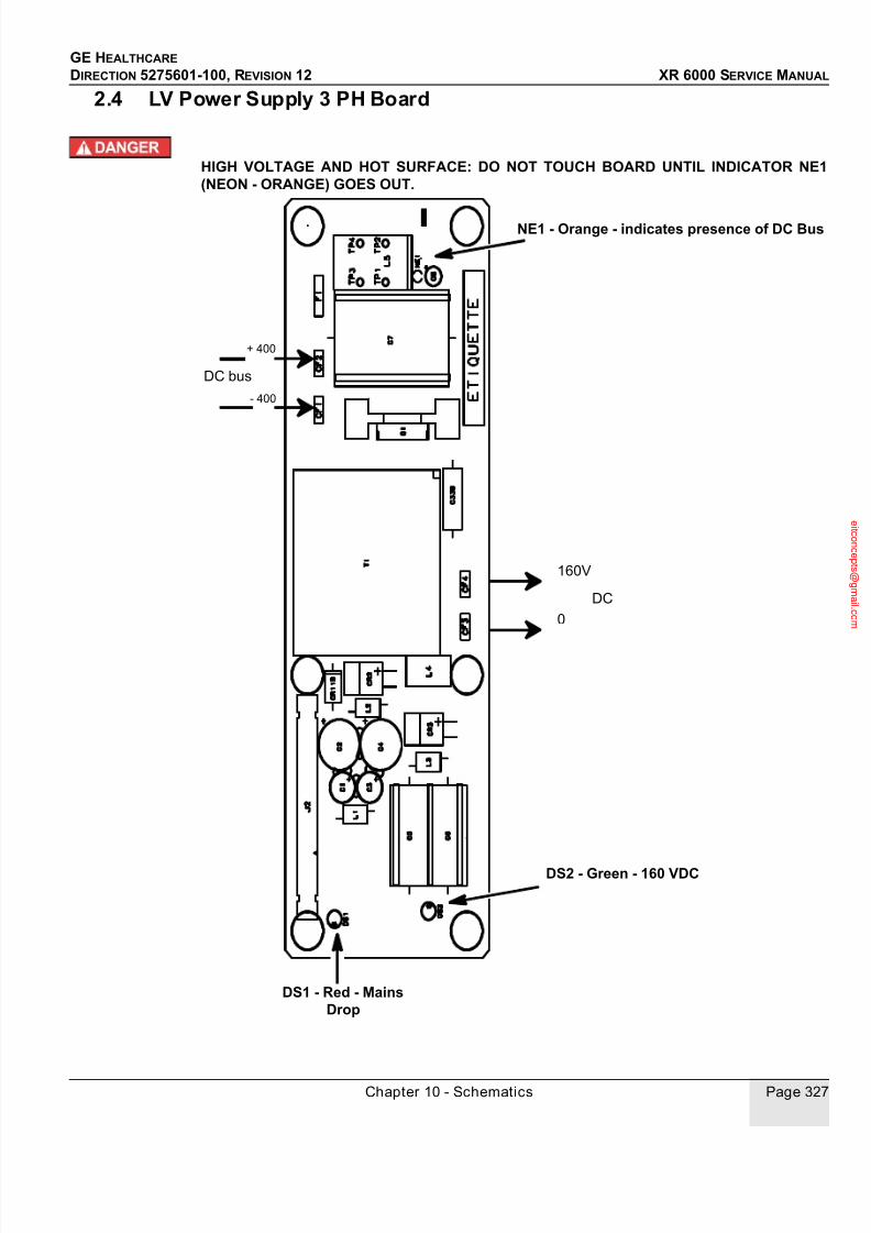
7/24/2019 GE XR6000 X-Ray - Service Manual
http://slidepdf.com/reader/full/ge-xr6000-x-ray-service-manual 327/421
GE HEALTHCARE
DIRECTION 5275601-100, REVISION 12 XR 6000 SERVICE MANUAL
Chapter 10 - Schematics Page 327
2.4 LV Power Supply 3 PH Board
HIGH VOLTAGE AND HOT SURFACE: DO NOT TOUCH BOARD UNTIL INDICATOR NE1(NEON - ORANGE) GOES OUT.
NE1 - Orange - indicates presence of DC Bus
DS2 - Green - 160 VDC
DS1 - Red - MainsDrop
- 400
DC bus
160V
+ 400
DC
0
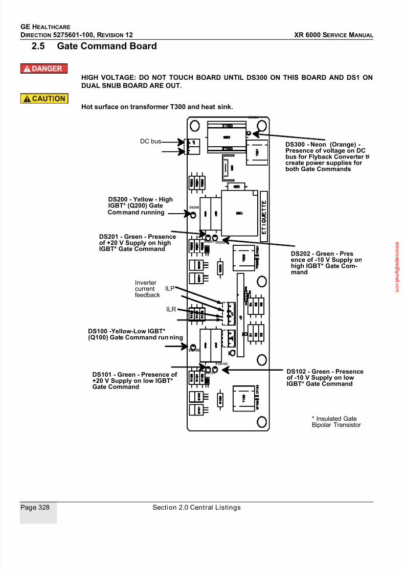
7/24/2019 GE XR6000 X-Ray - Service Manual
http://slidepdf.com/reader/full/ge-xr6000-x-ray-service-manual 328/421
GE HEALTHCARE
DIRECTION 5275601-100, REVISION 12 XR 6000 SERVICE MANUAL
Page 328 Section 2.0 Central Listings
2.5 Gate Command Board
HIGH VOLTAGE: DO NOT TOUCH BOARD UNTIL DS300 ON THIS BOARD AND DS1 ONDUAL SNUB BOARD ARE OUT.
Hot surface on transformer T300 and heat sink.
DS100
DS102
DS200
DS101
DS100 -Yellow-Low IGBT*(Q100) Gate Command run ning
DS101 - Green - Presence of +20 V Supply on low IGBT*Gate Command
DS200 - Yellow - HighIGBT* (Q200) GateCommand running
DS102 - Green - Presenceof -10 V Supply on lowIGBT* Gate Command
DS202 - Green - Presence of -10 V Supply onhigh IGBT* Gate Com-mand
DS300 - Neon (Orange) -Presence of voltage on DCbus for Flyback Converter tcreate power supplies for both Gate Commands
* Insulated GateBipolar Transistor
DS300
DS201 DS202
DS201 - Green - Presenceof +20 V Supply on highIGBT* Gate Command
DC bus
Inverter currentfeedback
ILP
ILR

7/24/2019 GE XR6000 X-Ray - Service Manual
http://slidepdf.com/reader/full/ge-xr6000-x-ray-service-manual 329/421
GE HEALTHCARE
DIRECTION 5275601-100, REVISION 12 XR 6000 SERVICE MANUAL
Chapter 10 - Schematics Page 329
2.6 Dual Snub Board
HIGH VOLTAGE: DO NOT GO INTO GENERATOR UNTIL INDICATOR DS1 (NEON - ORANGE)GOES OUT.
DS1 - Neon (Orange) - Indicates presence of voltage on DC Bus

7/24/2019 GE XR6000 X-Ray - Service Manual
http://slidepdf.com/reader/full/ge-xr6000-x-ray-service-manual 330/421
GE HEALTHCARE
DIRECTION 5275601-100, REVISION 12 XR 6000 SERVICE MANUAL
Page 330 Section 2.0 Central Listings
2.7 kV Control Board

7/24/2019 GE XR6000 X-Ray - Service Manual
http://slidepdf.com/reader/full/ge-xr6000-x-ray-service-manual 331/421
GE HEALTHCARE
DIRECTION 5275601-100, REVISION 12 XR 6000 SERVICE MANUAL
Chapter 10 - Schematics Page 331
2.7.1 Switches and Jumpers
2.7.2 Indicators
2.7.3 Non Volatile RAM
SWITCH OR JUMPER FUNCTION
RST RESET PUSH BUTTON
INDICATOR COLOR INDICATES:
CONF RED FIELD PROGRAMMABLE GATE ARRAY (FPGA)
CONFIGURATION NOT ACCOMPLISHED
OK YELLOW INVERTER GATE POWER SUPPLY OK
TX_TAV YELLOW TRANSMIT TO SERVICE LAPTOP
RX_TAV YELLOW RECEIVE FROM SERVICE LAPTOP
TX_CONS YELLOW TRANSMIT TO CONSOLE (IF EXISTING)RX_CONS YELLOW RECEIVE FROM CONSOLE (IF EXISTING)
T_CAN_X YELLOW SYSTEM CAN BUS TRANSMIT
R_CAN_X YELLOW SYSTEM CAN BUS RECEIVE
HALT RED MICROPROCESSOR HALTED
RESET RED BOARD BEING RESET
S0 TO S7 YELLOW STATUS LED
IN APPLICATION MODE THESE LEDS FLASH IN
SEQUENCE CONTINUOUSLY
DS1 GREEN -15V SUPPLY
DS2 GREEN +15V SUPPLY
REFERENCE DESIGNATION
U32 NON VOLATILE PARAMETERS RAM (BATTERY
INCLUDED)

7/24/2019 GE XR6000 X-Ray - Service Manual
http://slidepdf.com/reader/full/ge-xr6000-x-ray-service-manual 332/421
GE HEALTHCARE
DIRECTION 5275601-100, REVISION 12 XR 6000 SERVICE MANUAL
Page 332 Section 2.0 Central Listings
2.8 AC/DC 3 Phase board
HIGH VOLTAGE: DO NOT GO INTO GENERATOR UNTIL DS1 (NEON - ORANGE) GOES OUT.
Some components on this board can become very hot.

7/24/2019 GE XR6000 X-Ray - Service Manual
http://slidepdf.com/reader/full/ge-xr6000-x-ray-service-manual 333/421
GE HEALTHCARE
DIRECTION 5275601-100, REVISION 12 XR 6000 SERVICE MANUAL
Chapter 10 - Schematics Page 333
2.9 I/F Board RAD V1
TUBE
PUPT - Yellow -Data being sent to the console
Service Laptop
Console
N1 - Orange (neon) -Indicates presence of 100VAC for the
Presence of strap
Serial Link Configuration (RS422)
Room Door & Light
Wall Bucky
Table Bucky
ON & VAC
Pin 1
Pin 9
Pin 1
Pin 1
Pin 9
Pin 9

7/24/2019 GE XR6000 X-Ray - Service Manual
http://slidepdf.com/reader/full/ge-xr6000-x-ray-service-manual 334/421
GE HEALTHCARE
DIRECTION 5275601-100, REVISION 12 XR 6000 SERVICE MANUAL
Page 334 Section 2.0 Central Listings
2.10 I/F Board RAD V2
Service Laptop
Console
N1 - Orange (neon) - Indicates presence of100 VAC for the Bucky
Presence of strap -TUBE 1
Room Door & Light I/F
Wall Bucky
Table Bucky
ON & VAC
To AEC board
DS4: CAN TRANSMIT(yellow)
DS5: EXT.CANTRANSMIT (yellow)
OPTIONAL
No strap (engineeringuse)
DS3: Reset led (red)
DS1, DS2: Status micro
processor (yellow)
DS6: Receive Datafrom console (yellow)
DS7: DATA being sent toconsole (TRANSMIT)
(yellow)
Pin 1
Pin 9
Pin 1
Pin 9 Pin 1
Pin 9
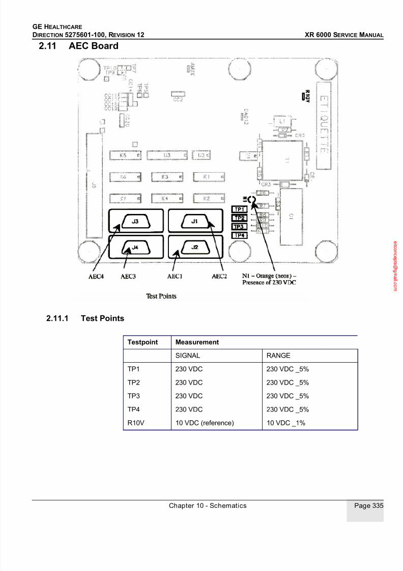
7/24/2019 GE XR6000 X-Ray - Service Manual
http://slidepdf.com/reader/full/ge-xr6000-x-ray-service-manual 335/421
GE HEALTHCARE
DIRECTION 5275601-100, REVISION 12 XR 6000 SERVICE MANUAL
Chapter 10 - Schematics Page 335
2.11 AEC Board
2.11.1 Test Points
Testpoint Measurement
SIGNAL RANGE
TP1 230 VDC 230 VDC _5%
TP2 230 VDC 230 VDC _5%
TP3 230 VDC 230 VDC _5%
TP4 230 VDC 230 VDC _5%
R10V 10 VDC (reference) 10 VDC _1%

7/24/2019 GE XR6000 X-Ray - Service Manual
http://slidepdf.com/reader/full/ge-xr6000-x-ray-service-manual 336/421
GE HEALTHCARE
DIRECTION 5275601-100, REVISION 12 XR 6000 SERVICE MANUAL
Page 336 Section 2.0 Central Listings
2.12 AEC Board V2
2.13 Test Points
N1 - Orange (neon) - Presence of 230 VDC AEC3 AEC4 AEC2AEC1
TESTPOINT MEASUREMENTSIGNAL RANGE
TP1 230 VDC 230 VDC _5%
TP2 230 VDC 230 VDC _5%
TP3 230 VDC 230 VDC _5%
TP4 230 VDC 230 VDC _5%
TP5 AEC assignment reference 0 to 10 V
TP6 10 VDC (reference) 10 VDC _1%
TP7 AEC return voltage
TP8 AEC1 return voltage
TP9 AEC2 return voltage
TP10 AEC3 return voltage
TP11 AEC4 return voltage

7/24/2019 GE XR6000 X-Ray - Service Manual
http://slidepdf.com/reader/full/ge-xr6000-x-ray-service-manual 337/421
GE HEALTHCARE
DIRECTION 5275601-100, REVISION 12 XR 6000 SERVICE MANUAL
Chapter 10 - Schematics Page 337
Section 3.0 Schematics
3.1 PDU Connection Diagram
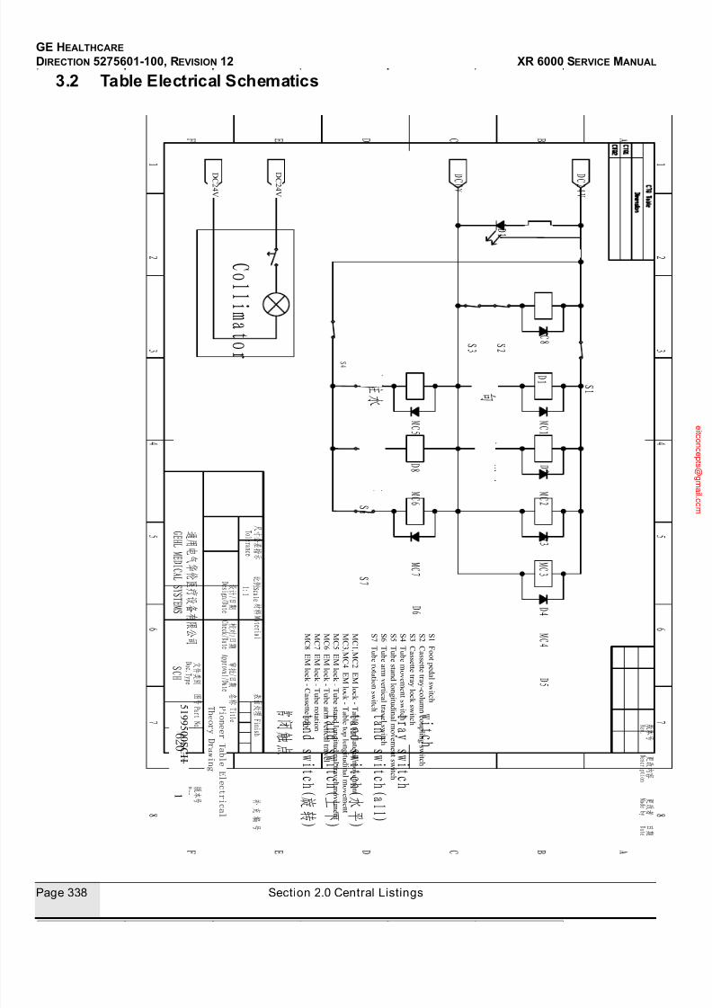
7/24/2019 GE XR6000 X-Ray - Service Manual
http://slidepdf.com/reader/full/ge-xr6000-x-ray-service-manual 338/421
GE HEALTHCARE
DIRECTION 5275601-100, REVISION 12 XR 6000 SERVICE MANUAL
Page 338 Section 2.0 Central Listings
3.2 Table Electrical Schematics
S 1 F o o t p e d a l s wi t c h
S 2 C a s s e t t e t r a y- c ol
umn c o u pl i n
g s wi t c h
S 3 C a s s e t t e t r a yl o c k s wi t c h
S 4 T u b e m o v e m e n t
s wi t c h
S 5 T u b e s t a n d l on
gi
t u d i n a l m o v e m e n t s wi t c h
S 6 T u b e a r m v e r t i c a
l t r a v e l s wi t c h
S 7 T u b e r o t a t i on s w
i t c h
M C 1 ,M C 2 E Ml o c k
-T a b l e t o pl a t e r a l m o v e m e n t
M C 3 ,M C 4 E Ml o c k
-T a b l e t o pl on
gi t u d i n a l m o v e m e n t
M C 5 E Ml o c k -T u b
e s t a n d l on
gi t u d i n a l t r a v e l m o v e m e n t
M C 6 E Ml o c k -T u b
e a r m v e t i c a l t r a v e l
M C 7 E Ml o c k -T u b
e r o t a t i on
M C 8 E Ml o c k - C a s
s e t t e t r a y
2
D C 2 4 V
D C 2 4 V
2 1
5 1 9 9 5 0 0 S C H

7/24/2019 GE XR6000 X-Ray - Service Manual
http://slidepdf.com/reader/full/ge-xr6000-x-ray-service-manual 339/421
GE HEALTHCARE
DIRECTION 5275601-100, REVISION 12 XR 6000 SERVICE MANUAL
Chapter 10 - Schematics Page 339
P i on e e r T a b l e C a b l e s A s s e m b l y
5 1 9 7
2 4 1 AD W
3
3

7/24/2019 GE XR6000 X-Ray - Service Manual
http://slidepdf.com/reader/full/ge-xr6000-x-ray-service-manual 340/421
GE HEALTHCARE
DIRECTION 5275601-100, REVISION 12 XR 6000 SERVICE MANUAL
Page 340 Section 2.0 Central Listings

7/24/2019 GE XR6000 X-Ray - Service Manual
http://slidepdf.com/reader/full/ge-xr6000-x-ray-service-manual 341/421
GE HEALTHCARE
DIRECTION 5275601-100, REVISION 12 XR 6000 SERVICE MANUAL
Chapter 10 - Schematics Page 341
3.3 A61001C Console Control Board Circuit Diagram
F r i
F e b
1 6
1 5 : 3 0 : 3 6
2 0 0 7
2
o f
1 5
t o t a l l o g i c
5 1 7 6 5 5 6 S C H
2
o f
2
2
I 1
I 4
I 3
I 5
I 7
I 6 I 8
C o m p a n y
R e s t r i c t e d
8
6
5
R e v
B S i z e
1
6
C D B
2
A
5
7
8
4
3
S h e e t
3
2
1
4
B l o c k
S h e e t
G E
H e a
l t h c a r e
7
D w g
N o
B l o c k
P a t h
M E M O R Y
A R M_
I O < 3 0 . . 0 >
L C D
D A T A < 3 1 . . 0 >
A D D R < 2 3 . . 0 >
A R M_
I O < 3 0 . . 0 > H
C L
K
A R M_
C O N < 9 . . 0 >
A R M_
R E S E T
J T A G
A R M_
R E S E T
C P L D_
J T A G < 3 . . 0 >
A R M_
J T A G < 5 . . 0 >
P O W E R
I N T E R F A C
E
I S P_
E N T E R
C P L D_
I O < 3 3 . . 0 >
A R M_
I O < 3 0 . . 0 >
A R M_
R E S E T
L E D < 6 . . 1 >
E P M 5 7 0
F E E D_
D O G
I S P_ E N
T E R
A R M_
I O < 3 0 . . 0 >
C P L D_
I O < 3 3 . . 0
>
L E D < 6 . . 1 >
H C L K
A D D R < 2 3 . . 0 >
D A T A < 3 1 . . 0 >
C P L D_
J T A G < 3 . . 0 >
C P L D_
C L K
A R M_
R E S E T
A R M_
C O N < 9 . . 0 >
L P C 2 2 9 4
F E E D_
D O G
D A T A < 3
1 . . 0 >
A D D R < 2 3 . . 0 >
A R M_
I O < 3 0 . . 0 >
A R M_
C O N < 9 . . 0 >
C P L D_
C L K
A R M_
R E S E T
A R M_
J T A G < 5 . . 0 >
C P L D_
J T A G < 3 . . 0 >
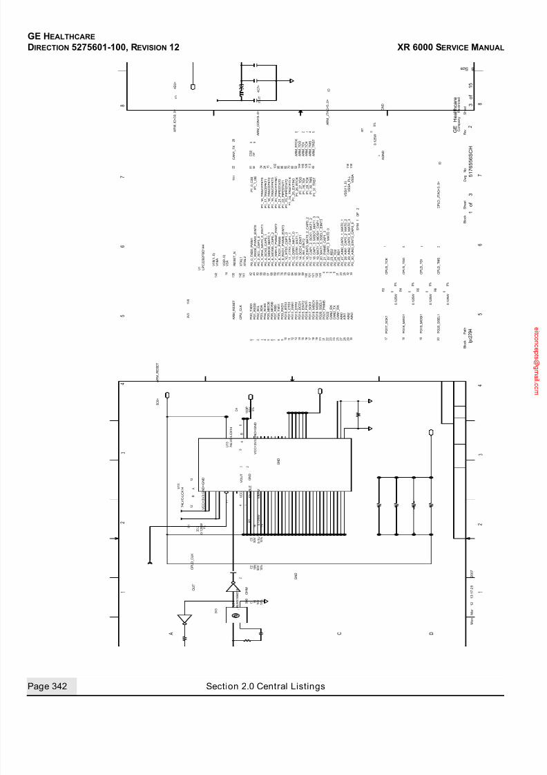
7/24/2019 GE XR6000 X-Ray - Service Manual
http://slidepdf.com/reader/full/ge-xr6000-x-ray-service-manual 342/421
GE HEALTHCARE
DIRECTION 5275601-100, REVISION 12 XR 6000 SERVICE MANUAL
Page 342 Section 2.0 Central Listings
M o n
M a r
1 2
1 3 : 1 7 : 2 8
2 0 0 7
3
o f
1 5
l p c 2 2 9 4
5 1 7 6 5 5 6 S C H
1
o f
3
2
4 D 3 >
5 C 6 >
4 C 7 >
1 K
2 0 2 1
1 4
2 2
A I N 0
C A N 2_ R X
2 5
2 4
A I N 1
P O 1 7_ S C K 1
0 . 1 2 5 W
V C C = 3 V 3 ; G N D = G N D
B L M 3 1 A 6 0 1 S
1
7 4 L V C - L C X 1 4
U 1 3
V C C = 3 V 3 ; G N D = G N D
1 3
7 4 L V C - L C X 1 4
1 0 %
3
4
2
Y 1
R 1
1 2
U 1 3
R 7
C 1
C 4
2
1
F L 3
8
9
R 6
R 5
R 4
R 3
1 4 1
1 4 2
1 3 8 1 3 9
1 4 3
2 2
1 3 5
4 3 1
1 3
1 2 6
1 4 0
1 4 4
5 2
7 0
8 2
8 6
9 5 1
0 2
9 0
7 1 5
2 4
3 4
7 6 7 5 6 9 6 1
5 9 5 8 3 3
5 0 3 2
2 5 2 3 2 1 8 5 4
1 2 3 4 9
1 2 2
1 2 1
1 0 1
1 0 0 9 9 9 2 8 5 8 4 8 3 7 8 4 2
U 1
1 %
G N D
C P U_ C L K
3 V 3
A R M_ I O < 3 0 . . 0 >
2 6
A R M_ T D O
P O 1 2_ D S R 1
0 . 1 2 5 W
1 3
1 2
1 1
P O 2 0_ S S E L 1
P O 1 1_ C T S 1
P O 1 0_ R T S 1
0
1 V 8
3 V 3
A G N D
G N D
G N D
1 0 0 P
C P L D_ C L K
0 . 1 2 5 W 1 %
3 3 . 2
5 %
0
2 3 0
0 . 1 2 5 W
1 7
4
P O 6_ M O S I 0
0
0 . 1 2 5 W
0
0 %
A R M_ R E S E T
2
P O 1 3_ D T R 1
P O 9_ R X D 1
P O 4_ S C K 0
P O 2_ S C L
P O 1 5_ E I N T 2
P O 1 4_ D C D 1
8
1 0 N
1 6 V
1 0 %
0 . 1 2 5 W
0 %
1 9
2 0
1
A R M_ T D I
A R M_ T C K
2 3
A R M_ R E S E T
L P C 2 2 9 2 F B D 1 4 4
1 7 9 1 4
1 6 1 7 1 8
2 7 2 8
3 0
0 . 1 2 5 W
1
0
C P
L D_ T D I
0 %
0 %
C P
L D_ T D O
C P L D_ J T A G < 3 . . 0 >
1 8
C P
L D_ T C K
0 %
5 0 V
6 0 0
O H M
P O 7_ S S E L
C P
L D_ T M S
P O 1 9_ M O S I 1
P O 1 8_ M I S O 1
1 U
P O 1 7_ S C K 1
1 9
0
. 1 U
2 3
C A N 1_ R X
C A N 2_ T X
A I N 3
1 5
6 5 3 0
5 0 V
P O 1 8_ M I S O 1
P O 1 6_ E I N T 0
P O 8_ T X D 1
P O 5_ M I S O 0
P O 3_ S D A
P O 1_ R X D 0
C A N 1_ T X
9 1
6
P O 1 9_ M O S I 1
P O 2 1_ P W M 5
P O 2 0_ S S E L 1
A I N 2
2 9
P O 2 2
5 0 V
C 2
C 3
R 2
1 0
1 0 %
1 0 M H Z
P O 0_ T X D 0
6 8
0
C S 0
9
O E
A R M_ C O N < 9 . . 0 >
4
A R M_ T R S T
5
A R M_ T M S
0
A R M_ J T A G < 5 . . 0 >
A R M_ R T C K
6 0
C o m p a n y
R e s t r i c t e d
8
6
5
R e v
B S i z e
1
6
C D B
2
A
5
7
8
4
3
S h e e t
3
2
1
4
B l o c k
S h e e t
G E
H e a l t h c a r e
7
D w g
N o
B l o c k
P a t h
A
O U T
I O
A
B
V C C
V O U T
G N D
E N A B L E
O U T
A
B
I O
I O
S Y M
1
O F
2
P 0_ 0_ T X D 0_ P W M 1
P 0_ 2_ S C L_ C A P 0_ 0
P 0_ 4_ S C K 0_ C A P 0_ 1
P 0_ 5_ M I S O 0_ M A T 0_ 1
P 0_ 7_ S S E L 0_ P W M 2_ E I N T 2
P 0_ 9_ R X D 1_ P W M 6_ E I N T 3
P 0_ 1 0_ R T S 1_ C A P 1_ 0
P 0_ 1 2_ D S R 1_ M A T 1_ 0
P 0_ 1 3_ D T R 1_ M A T 1_ 1
P 0_ 1 4_ D C D 1_ E I N T 1
P 0_ 2 2_ C A P 0_ 0_ M A T 0_ 0
P 0_ 2 1_ P W M 5_ C A P 1_ 3
X T A L 2
T D 1
V 1 8 ( 1 . . 0 )
V S S ( 1 1 . . 0 )
V S S A_ P L L
V S S A
P 1_ 2 9_ T C K
P 1_ 2 8_ T D I
P 1_ 2 6_ R T C K
P 1_ 2 4_ T R A C E C L K
P 0_ 1_ R X D 0_ P W M 3_ E I N T 0
P 0_ 1 1_ C T S 1_ C A P 1_ 1
P 1_ 2 7_ T D O
P 1_ 2 5_ E X T I N 0
P 1_ 2 3_ P I P E S T A T 2
V 3 A
P 1_ 1 6_ T R A C E P K T 0
P 1_ 1 7_ T R A C E P K T 1
P 1_ 2 2_ P I P E S T A T 1
P 1_ 2 1_ P I P E S T A T 0
P 1_ 2 0_ T R A C E S Y N C
P 1_ 1 8_ T R A C E P K T 2
P 1_ 1 9_ T R A C E P K T 3
P 1_ 0_ C S 0
P 1_ 1_ O E
P 1_ 3 0_ T M S
P 1_ 3 1_ T R S T
X T A L 1
P 0_ 3_ S D A_ M A T 0_ 0_ E I N T 1
P 0_ 1 6_ E I N T 0_ M A T 0_ 2_ C A P 0_ 2
P 0_ 1 9_ M A T 1_ 2_ M O S I 1_ C A P 1_ 2
V 1 8 A
V 3 ( 9 . . 0 )
R E S E T_ N
P 0_ 6_ M O S I 0_ C A P 0_ 2
P 0_ 8_ T X D 1_ P W M 4
P 0_ 1 5_ R I 1_ E I N T 2
P 0_ 1 7_ C A P 1_ 2_ S C K 1_ M A T 1_ 2
P 0_ 1 8_ C A P 1_ 3_ M I S O 1_ M A T 1_ 3
P 0_ 2 0_ M A T 1_ 3_ S S E L 1_ E I N T 3
P 0_ 3 0_ A I N 3_ E I N T 3_ C A P 0_ 0
P 0_ 2 9_ A I N 2_ C A P 0_ 3_ M A T 0_ 3
P 0_ 2 8_ A I N 1_ C A P 0_ 2_ M A T 0_ 2
P 0_ 2 7_ A I N 0_ C A P 0_ 1_ M A T 0_ 1
P 0_ 2 5_ R D 1
P 0_ 2 4_ T D 2
P 0_ 2 3_ R D 2
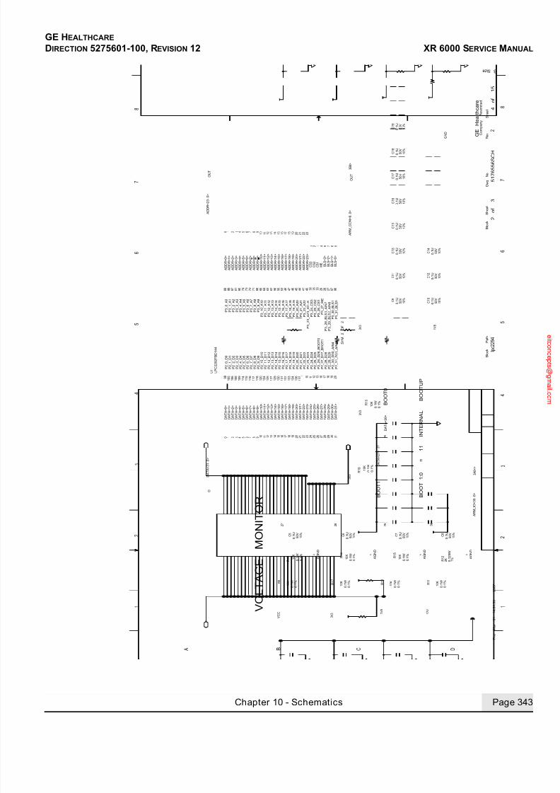
7/24/2019 GE XR6000 X-Ray - Service Manual
http://slidepdf.com/reader/full/ge-xr6000-x-ray-service-manual 343/421
GE HEALTHCARE
DIRECTION 5275601-100, REVISION 12 XR 6000 SERVICE MANUAL
Chapter 10 - Schematics Page 343
B O O T 1 : 0
=
1 1
I N T E R N A
L
B O O T U P
B O O T 0
B O O T 1
V O L T A G E
M O N I T O R
T h u
M a r
0 1
1 4 : 3 1 : 5 9
2 0 0 7
4
o f
1 5
l p c 2 2 9 4
5 1 7 6 5 5 6 S C H
2
o f
3
2
3 B 8 >
3 A 8 < >
1 V 8
0 . 1 %
R 1 7
0 . 1 W
1 0 K 0 . 1 W A G
N D
0 . 1 %
0 . 1 W
C 5
2 7
R 1 9
R 1 2
R 1 1
C 8
R 1 6
R 1
5
R 1
4
R 1 3
R 1 0
R 8
C 1 9
C 1 8
C 1 7
C 1 0
C
1 2
C 1 4
C 1 6
C 1 5
C 1 3
C
1 1
C 9
C 6
C 7
6 6
7 1
7 2
7 3
7 4
8 0
8 1
9 6
9 7
8 7
2 7
2 8
2 9
3 0
3 5
3 6
4 0
4 1
4 4
4 5
8 8
4 6
4 7
4 8
5 3
5 5
5 6
6 2
6 3
6 4
6 5
8 9
1 1 8
1 1 7
1 1 6
1 1 5
1 1 4
1 0 9
1 0 8 2
0 1 9
1 0 6 1
8 1 7
1 6
1 3
1 2
1 1
1 0 1
1 3 7
1 3 6
1 0 5
1 3 4
1 3 3
1 3 2
1 3 1
1 3 0
1 2 9
1 2 7
1 2 5
1 2 4
1 2 0 9
8
U 1
2 7
6 5
B L S < 2 >
B L S < 1 >
4 2 1
2 7
3 1
4
2 3
2 2
2 1
2 0
1 9
1 8
1 7
1 6
1 5
1 4
1 3
1 2
1 1
1 0 9 8 7 6 5 3 2 1
2 9
2 8
2 6
2 5
2 4
2 3
1 9
1 8
1 7
1 6
1 5
1 3
1 1
1 0
7 6 5 3 2 1 0
B L S < 0 >
C S 1
1 2
0
2 1
1 V 8
1 0 %
5 0 V
0 . 1 U
0 . 1 U 5 0 V
0 . 1 U 5 0 V 1 0 %
5 0 V
0 . 1 U
0 . 1 U 5 0 V 1 0 %
0 . 1 U 5 0 V
1 0 %
5 0 V
0 . 1 U
0 . 1 U
1 0 %
5 0 V
0 . 1 U
1 0 %
5 0 V
0 . 1 U
3 0
2 2
5 0 V
3 V 3
4
0 . 1 %
0 . 1 W
0 . 1 U 5 0 V
2 9
1 0 %
1 0 K
1 0 K
1 0 %
1 0 %
2 8
3 V 3
1 0 K
0 . 1 U
1 0 %
V C C
1 4
9 2 0
A R M_ C O N < 9 . . 0 >
L P C 2 2 9 2 F B D 1 4 4
C S 2
3 7 8
D A
T A < 3 1 >
D A
T A < 3 0 >
D A
T A < 2 9 >
D A
T A < 2 8 >
D A
T A < 2 7 >
D A
T A < 2 6 >
D A
T A < 2 5 >
D A
T A < 2 4 >
D A
T A < 2 3 >
D A
T A < 2 2 >
D A
T A < 2 1 >
D A
T A < 2 0 >
D A
T A < 1 9 >
D A
T A < 1 8 >
D A
T A < 1 7 >
D A
T A < 1 6 >
D A
T A < 1 5 >
D A
T A < 1 4 >
D A
T A < 1 3 >
D A
T A < 1 1 >
D A
T A < 1 0 >
D A
T A < 9 >
D A
T A < 8 >
D A
T A < 7 >
D A
T A < 5 >
D A
T A < 4 >
D A
T A < 3 >
D A
T A < 2 >
D A
T A < 1 >
D A
T A < 0 >
A D D R < 2 0 >
A D D R < 1 9 >
A D D R < 1 8 >
A D D R < 1 7 >
A D D R < 1 6 >
A D D R < 1 5 >
A D D R < 1 4 >
A D D R < 1 3 >
A D D R < 1 2 >
A D D R < 1 1 >
A D D R < 9 >
A D D R < 8 >
A D D R < 7 >
A D D R < 6 >
A D D R < 5 >
A D D R < 4 >
A D D R < 3 >
A D D R < 2 >
A D D R < 1 >
A D D R < 0 >
A D D R < 2 1 >
A D D R < 2 3 >
A D D R < 2 2 >
A D D R < 2 3 . . 0 >
D A T A < 3 1 . . 0 >
0 . 1 % A G
N D
A G
N D
0 . 1 U
1 0 %
5 0 V
0 . 1 % 1 0 K
3 0
A R M_ I O < 3 0 . . 0 >
3 V 3
1 0 %
1 2 V
1 0 K
0 . 1 W
A G
N D
1 0 K
0 . 1 W
0 . 1 %
2 K
5 0 V
0 . 1 U
0 . 1 2 5 W
1 %
A D D R < 1 0 >
D A
T A < 1 2 >
2 6
0 . 1 W
0 . 1 %
G N D
1 0 K
1 0 K
D A
T A < 6 >
8
C S 3
W E B L S < 3 >
0 . 1 % D
A T A < 2 7 >
3 V 3
0 . 1 W
0 . 1 %
1 0 %
D A T A < 2 6 >
0 . 1 W
1 0 %
0 . 1 U
5 0 V
1 0 %
5 0 V
C o m p a n y
R e s t r i c t e d
8
6
5
R e v
B S i z e
1
6
C D B
2
A
5
7
8
4
3
S h e e t
3
2
1
4
B l o c k
S h e e t
G E
H e a l t h c a r e
7
D w g
N o
B l o c k
P a t h
O U T
S Y M
2
O F
2
P 2_ 3 1_ D 3 1_ A I N 5
P 3_ 2 9_ B L S 2_ A I N 6
P 3_ 2_ A 2
P 3_ 2 5_ C S 2
P 3_ 2 4_ C S 3
P 3_ 2 3_ A 2 3_ X C L K
P 3_ 2 2_ A 2 2
P 3_ 4_ A 4
P 2_ 2 7_ D 2 7_ B O O T 1
P 2_ 2 9_ D 2 9
P 2_ 3 0_ D 3 0_ A I N 4
P 2_ 2 8_ D 2 8
P 2_ 2 6_ D 2 6_ B O O T 0
P 2_ 2 5_ D 2 5
P 2_ 2 4_ D 2 4
P 2_ 2 3_ D 2 3
P 2_ 2 2_ D 2 2
P 2_ 2 1_ D 2 1
P 2_ 2 0_ D 2 0
P 2_ 1 9_ D 1 9
P 2_ 1 8_ D 1 8
P 2_ 1 7_ D 1 7
P 2_ 1 6_ D 1 6
P 3_ 3 1_ B L S 0
P 3_ 3 0_ B L S 1
P 3_ 2 8_ B L S 3_ A I N 7
P 3_ 2 7_ W E
P 3_ 2 6_ C S 1
P 3_ 2 0_ A 2 0
P 3_ 2 1_ A 2 1
P 3_ 1 9_ A 1 9
P 3_ 1 8_ A 1 8
P 3_ 1 7_ A 1 7
P 3_ 1 6_ A 1 6
P 3_ 1 5_ A 1 5
P 3_ 1 3_ A 1 3
P 3_ 1 4_ A 1 4
P 3_ 1 2_ A 1 2
P 3_ 1 1_ A 1 1
P 3_ 1 0_ A 1 0
P 3_ 9_ A 9
P 3_ 8_ A 8
P 3_ 7_ A 7
P 3_ 5_ A 5
P 3_ 6_ A 6
P 3_ 3_ A 3
P 3_ 1_ A 1
P 3_ 0_ A 0
P 2_ 1 4_ D 1 4
P 2_ 1 3_ D 1 3
P 2_ 3_ D 3
P 2_ 1 5_ D 1 5
P 2_ 0_ D 0
P 2_ 1_ D 1
P 2_ 2_ D 2
P 2_ 4_ D 4
P 2_ 5_ D 5
P 2_ 8_ D 8
P 2_ 1 1_ D 1 1
P 2_ 1 2_ D 1 2
P 2_ 1 0_ D 1 0
P 2_ 9_ D 9
P 2_ 7_ D 7
P 2_ 6_ D 6
A
O U T
I O
A A A

7/24/2019 GE XR6000 X-Ray - Service Manual
http://slidepdf.com/reader/full/ge-xr6000-x-ray-service-manual 344/421
GE HEALTHCARE
DIRECTION 5275601-100, REVISION 12 XR 6000 SERVICE MANUAL
Page 344 Section 2.0 Central Listings
T R P = 2 . 6 7 * C R S T = 1 2 5 . 5 M S
E X T E N D E D
M O D E
T W D = 2 . 6
7 * C S W * 5 0 0 = 6 . 3 S
A R M
R E S E T
&
W A T C H D O G
T h u
M a r
0 1
1 4 : 3 2 : 0 2
2 0 0 7
5
o f
1 5
l p c 2 2 9 4
5 1 7 6 5 5 6 S C H
3
o f
3
2
3 A 4 <
R 9
1 %
1
S 1 K T 1 1 B 1 J M
3
0 . 1 2 5 W
1 0 V
J U M P E R
R 2 0
2 . 4 9 K 0 . 1 2 5 W
F E E D_ D O G
R 1 8
1 %
V C C 1
0 K 0 . 1 2 5 W
2
G N D
2 . 2 U
5 0 V
5 0 V 1 0 %
C 2 3
1 0 %
V C C
C 2 0
4 . 7 N
3 V 3
C 2 1
1 0 K
1 %
J 3
R 2 1
0 . 1 U
2
1 %
0 . 1 2 5 W
A R
M_ R E S E T
1 %
0 . 1 2 5 W 2 0 K
R 2 2
1 0 %
G N D
C 2 2
U 2 4
M A X 6 3 0 1
5
5 V
6 8 4 3
7
1
2
1 0 %
5 0 V
4 7 N
4
1 K
G N D
1
C o m p a n y
R e s t r i c t e d
8
6
5
R e
v
B S i z e
1
6
C D B
2
A
5
7
8
4
3
S h e e t
3
2
1
4
B l o c k
S h e e t
G
E
H e a l t h c a r e
7
D w g
N o
B l o c k
P a t h
I N
2 1
3 4
O U T
V C C
W D I
R E S E T_ I N
W D S
S R T
S W T
R E S E T_ N
G N D
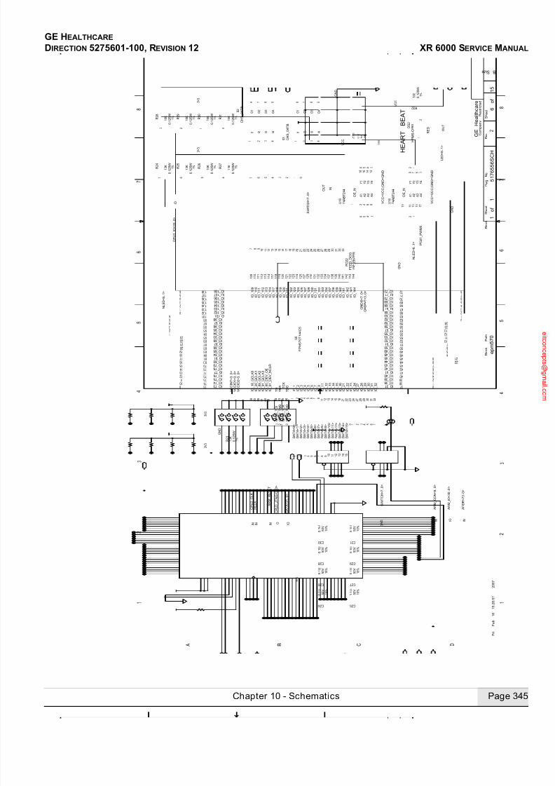
7/24/2019 GE XR6000 X-Ray - Service Manual
http://slidepdf.com/reader/full/ge-xr6000-x-ray-service-manual 345/421
GE HEALTHCARE
DIRECTION 5275601-100, REVISION 12 XR 6000 SERVICE MANUAL
Chapter 10 - Schematics Page 345
H E A R
T
B E A T
F r i
F e b
1 6
1 5 : 2 8 : 5 1
2 0 0 7
6
o f
1 5
e p m 5 7 0
5 1 7 6 5 5 6 S C H
1
o f
1
2
9
6
1
0
1 5
1 4
1 3
1 2
1 1
1 0
7 6 5 4 3 2 1 0
2
5
8
5
7
1 0
1 2
2 3
0
1
2
2 4
3
4
5
6
7
8
9 8 7 6 5 4 3 2 1 0
0 1 2
9
1 0
1 1
1 2
1 3 1 4
1 5
1 6
1 7
1 8 1 9
2 0
2 1
2 2
2 3
2
1
3
4
5
0
6
1
3
4
5
6
A D D R < 2 3 . . 0 >
A R M_ C O N < 9 . . 0 >
7 8 9 1 1
1 3 1 4 1 5 1 6 1 7
1 9 2 0 2 1
2 3 2 4
3 1
C H
S_ 0 4 T B
1 %
1 0 K
0 . 1 2 5 W
3
1 %
0 . 1 2 5 W
1 0 K
2
3 V 3
0 . 1 2 5 W
1 0 K
1 %
1 %
1 0 K
0 . 1 2 5 W
1 0
1 %
1 0 K
0 . 1 2 5 W
0 . 1 2 5 W
1 0 K
1 %
6 7
3 V 3
1 %
1 0 K
0 . 1 2 5 W
1 0 K
0 . 1 2 5 W 1 %
7 6 5 4 5
C H S_ 0 4 T B
4 3 2 1 0
1 %
3 3 2 0 . 1 2 5 W
6 5 4 3 1 2
4 1
G N D
L E D < 6 . . 1 >
2 1
6
2 7 2 8
1 8
2
2
D A T A < 1 4 >
D A T A < 1 5 >
D A T A < 8 >
D A T A < 6 >
D A T A < 7 >
D A T A < 9 >
D A T A < 1 0 >
D A T A < 1 2 >
D A T A < 1 3 >
C P L D_ T D O
N L E D < 6 . . 1 >
3 V 3
1 0 %
0 . 1 U
1 0 %
5 0 V
5 0 V
1 0
%
0 . 1 U
0 . 1 U
1 0 %
5 0 V
5 0 V
5 0 V 1 0 %
5 0 V 1 0 %
3 V 3
G N D
D A T A < 3 1 . . 0 >
H C L K
A R M_ R E S E T
C P L D_ T C K
3
D A T A < 4 >
D A T A < 3 >
D A T A < 2 >
S W I T C H < 7 . . 0 >
3
1 2
4
D A T A < 1 >
D A T A < 0 >
3 V 3
C P L D_ T M S
E P M 5 7 0 T 1 4 4 C 5
5 0 V
G N D
0 . 1 U
S W I T C H < 7 . . 0 >
G N D
1 0 K
0 . 1 2 5 W
1 %
5 0 V 1 0 %
1 0
%
0 . 1 U
0 . 1 U
D A T A < 5 >
5 0 V
0 . 1 U
C 2 4
C 2 6
C 2 8
C 3 0 C 3 1
C 2 5
C 2 7
C 2 9
S 3 1 2 3 4
8 7 6 5
R 3 0
R 2 9
R 2 8
R 3 1
S 2
1 2 3 4
8 7 6 5
R 2 7
R 2 4
R 2 5
R 2 6
R 2 3
2
1
R 3 2
U 6
1
1 0 1
1 0 2 1 0 3 1 0 4 1 0 5 1 0 6 1 0 7
1 0 8
1 0 9
1 1
1 1 2 1 1 7 1 1 8 1 1 9
1 2
1 2 0 1 2 1 1 2 2 1 2 3 1 2 5 1 2 7
1 3
1 3 3 1 3 4 1 3 7
1 4 1 5 1 6
1 8 2
2 1 2 2 2 3 2 4 2 7 2 8 2 9 3
3 0
3 1 3 2
3 7
3 8
3 9
4
4 0 4 1
4 2
4 3
4 4
4 5 4 8
4 9
5
5 0
5 1
5 2 5 3
5 5
5 7
5 8
5 9
6
6 0
6 2
6 3
6 6
6 7
6 8 6 9
7
7 0
7 1
7 2
7 3
7 4
7 5
7 6 7 7
7 8
7 9
8
8 0
8 1 8 4
8 5
8 6
8 7
8 8
8 9 9 1
9 3
9 4
9 5
9 6
9 7 9 8
3 5
3 4
3 6
3 3
G N D
G N D
C
3 2
1 0 %
V C C = V C C ; G N D = G N D 1
6 1 4
6 8 4 7
4 A B T 2 4 4
9 7 3 5
1 5 1 7
1 3
1 1
1 9
U 1 6
P O 2 1_ P W M 5
V C C
V C C
D S 2
H S M
S - C 6 5 0
R E D
V C C = V C C ; G N D = G N D
C P L D_ J T A G < 3 . . 0 >
C P L D_ C L K
3 0
1 3 1 1 3 2
2 6
1 2 9
2 9
1 3 0
3 3
1 2 4
2 0
1 0
C P L D_ I O < 3 3 . . 0 >
1 1 0 1 1 1
6 1
1 1 4 1 1 3
0 . 1 U
1 3 8
4
1 3
1 1
7
A R M_ I O < 3 0 . . 0 >
N L E D < 6 . . 1 >
2 2
1 4 3 1 4 1 1 3 9
3 2
1 4 2
2 2
1 4 4
0 . 1 U
D A T A < 1 1 >
F E E D_ D O G
1 2
1 8
2 1
5 6
I S P_ E N T E R
2 5
C P L D_ T D I
7 4 A B T 2 4 4
U 1 6
P O 2 2
1 4 0
C o m p a n y
R e s t r i c t e d
8
6
5
R
e v
B S i z e
1
6
C D B
2
A
5
7
8
4
3
S h e e t
3
2
1
4
B l o c k
S h e e t
G E
H e a l t h c a r e
7
D w g
N o
B l o c k
P a t h
I N
O U T
I N
O E_ N
A 1 A 2
A 4
A 3
Y 3 Y 4
Y 2
Y 1
O E_ N
A 1 A 2
A 4
A 3
Y 3 Y 4
Y 2
Y 1
I O
I N I O I N
I O
I O_ 6 0_ D E V_ O E
I O_ 6 1_ D E V_ N C L R
I O_ 1 8_ G C L K 0
T C K
T D O
T M S
T D I
I O_ 9 1_ G C L K 3
I O _ 7 5
I O _ 7 8
I O_ 1 6
I O_ 1 4
I O_ 1 5
I O_ 1 3
I O_ 1 2
I O_
8
I O_
7
I O_
1 1
I O_
3
I O_
5
I O_
6
I O_
4
I O_
2
I O_
1
I O_ 3 2
I O_
3 1
I O_ 3 0
I O_ 2 9
I O_
2 7
I O_ 2 2
I O_ 2 8
I O_
2 1
V C C I O 1 < 3 . . 0 >
V C C I O 2 < 3 . . 0 >
V C C I N T < 3 . . 0 >
I O_ 2 4
I O_ 2 3
I O _ 7 2
I O _ 7 0 I O _ 7 1
I O _ 6 7
I O _ 6 9 I O _ 6 8
I O _ 6 6 I O _ 6 3 I O _ 6 2
I O _ 5 8 I O _ 5 9
I O _ 5 5 I O _ 5 7
I O _ 5 1 I O _ 5 2 I O _ 5 3
I O _ 4 4
I O _ 4 8 I O _ 4 5
I O _ 5 0 I O _ 4 9
I O _ 4 3 I O _ 4 2
I O _ 4 0 I O _ 4 1
I O _ 3 9
I O _ 3 7 I O _ 3 8
I O _ 1 0 4
I O _ 1 0 1
I O _ 9 7
I O _ 9 5
I O _ 9 3
I O _ 8 7
I O _ 8 1
I O _ 7 3 I O _ 7 4
I O _ 7 9
I O_ 1 0 9
I O_ 1 1 0
I O_ 1 1 9
I O_
1 2 1
I O_ 1 2 2
I O_ 1 2 4
I O_ 1 2 5
I O_ 1 2 7
I O_ 1 2 9
I O_ 1 3 0
I O_
1 3 1
I O_ 1 3 3
I O_ 1 3 2
I O_ 1 3 4
I O_ 1 3 7
I O_ 1 3 8
I O_ 1 4 0
I O_ 1 3 9
I O_ 1 4 2
I O_
1 4 1
I O_ 1 4 3
I O_ 1 4 4
I O_ 1 1 7
I O_ 1 1 3
I O_
1 1 1
I O _ 1 0 7 I O _ 1 0 6 I O
_ 1 2 3
I O_ 1 2 0
I O_ 1 1 8
I O_ 1 1 4
I O_ 1 1 2 I O _ 1 0 8
G N D I N T < 3 . . 0 >
G N D I 0 < 7 . . 0 >
I O _ 8 5
I O _ 7 6 I O _ 7 7
I O _ 8 0
I O _ 8 4
I O _ 8 6
I O _ 8 8
I O _ 9 4
I O _ 9 6
I O _ 9 8
I O _ 1 0 2 I O _ 1 0 3
I O _ 1 0 5
I O_ 2 0_ G C L K 1
I O_ 8 9_ G C L K 2
O U T
I N
O 1
I 3 I 2 I 4 I 1
O 4
O 3
O 2
O 1
I 3 I 2 I 4 I 1
O 4
O 3
O 2
I N I O

7/24/2019 GE XR6000 X-Ray - Service Manual
http://slidepdf.com/reader/full/ge-xr6000-x-ray-service-manual 346/421
GE HEALTHCARE
DIRECTION 5275601-100, REVISION 12 XR 6000 SERVICE MANUAL
Page 346 Section 2.0 Central Listings
P O W E R
C O N N E C T O R
H A N D L E C
O N N E C T O R
C P L D_
I N T E R L O C K
C P L D_
P R E P
C P L D_
E X P
M o n
M a r
1 2
1 3 : 5 3 : 0 7
2 0 0 7
7
o f
1 5
i n t e r f a c e
5 1 7 6 5 5 6 S C H
1
o f
5
2
5 0
O H M
7 D 1 <
P R E P
E X P
7 D 1 <
G N D
C P L D_
I O < 3 >
3 9
G N D
C 3 6
0 . 1 U
P D U G N D
9 B 3 <
1 0 D 4 <
1 0 C 6 >
1
1 D 3 < >
9 B 3 < >
1 0 B 1 < >
1 1 C 8 < >
7 A 8 <
7 B 5 >
7 C 1 <
7 A 8 >
7 C 7 >
7 C 7 >
2 0 K
R 3 9
5 0 V
R 4 4
R 4 1
2 0 K 0 . 1 2 5 W
1 %
R 4 0
2 0 K 0 . 1 2 5 W
1 0 %
1 5 K
R 4 7
2 0 K
1 %
1 2 V
R 4 6
G N D
2
J 4
O V E R_
C U R R E N T
0 . 1 U
0 . 1 2 5 W
R 4 3
1 5 K
G N D
3
U 1 4
P D U G N D
5
C 3 5 1
3
1 1
0 . 1 U
C 3 4
U 1 4
M C 1 4 8 9 A
9
0 . 1 2 5 W
5 1 2
1 5
1 3
1 1
1
M H P 4_
5 0 T B 1 0_
0 0
1 %
8
1 9
F L 5
C 3 3
6
4 1 0
F 1
R 3 3
R 3 7
R 3 8
R 3 6
3 8 1
5
6
K 2
4
1
5
6
2
5 7
1 7
U 8
C R 1
C R 2
2
1
F L 4
3
1
6 5 4
3 2 1
J 6
4
2 1
8
4 7 2 1
3 6
K 1
M H 2
1 M H 3
1 M H 7
1 M H 6
1 M H 5
1 M H 8
1 M H 4
1
D 3
2
1
Q 2
Q 1
C 3 7
R 4 8
C 3 9
R 4 5
D 1
4 3 2 1
J 7
1 2 V
G N D
G N D
5 0 V
5 0 V
0 . 1 U
1 %
G N D
1 2 V
B L M 3 1 P 5 0 0 S
A Z 7 4 2 - 2 C - 2 4 D
M C 1 4 8 9 A
2 A
2 0 0 V
6 . 7 V
0 1
S M B J 5 . 0
6 . 7 V
0 . 1 2 5 W 1 %
4 . 9 9 K
1 %
0 . 1 2 5 W
1 5 K
4 0 V
2
4 . 9 9 K
0 . 1 2 5 W
1 5 K
0 . 1 2 5 W
1 %
P D U 2 4 V
2
C P L D_
I O < 1 >
P D U 2 4 V
P I N
S H I E L D
S H I E L D
G N D
M H P 4_
5 0 T B 1 0_
0 0
M H P 4_
5 0 T B 1 0_
0 0
M H P 4_
5 0 T B 1 0_
0 0
M H P 4_
5 0 T B 1 0_
0 0
M H P 4_
5 0 T B 1 0_
0 0
1
W
I R E_
T O_
B O A R D 2
2 N
2 0 %
2 5 0 V
1 %
1 M E G
0 . 1 2 5 W
3
X_
R A Y_
L I G H T
1 %
G 6 B_ 2 1 1 4 P_ U S 2 4 V D C
4 0 V
L S M 3 4 0 J
P D U G N D
2 4 V_
I N
L S M 3 4 0 J
0 . 1 2 5 W
1 0 K
0
X R A Y_
O N_
L I G H T
R I G H T_
A N G L E
P I N
P D U G N D
M U R S 3 2 0 T 3
5 0
O H M
1 0 %
5 0
O H M
5 0 V
1 0 %
V C C
5 0 V
3 V 3
V C C = 3 V 3 ; G N
D = G N D
1 5 K
1 0 %
V C C = V C C ; G N D = G N D
1 %
0 . 1 2 5 W 1 %
1 %
V C C = V C C ; G N D = G N D
M C 1 4 8 9 A
0 . 1 2 5 W
1 %
R 4 2
1 5 K
U 1 4
V C C = V C C ; G N D = G N D
1 0 %
V C C
O N / O F F_
K E Y < 3 . . 0 >
M M B T 3 9 0 4
D 2
P D U G N D
7 4 L V C_
L C X 2
4 4
C P L D_
I O < 0 >
C P L D_
I O < 2 >
S M B J 5 . 0
1 2 V
M C 1 4 8 9 A
U 1 4
1 0 %
5 0 V
0 . 1 2 5 W
B L M 3 1 P 5 0 0 S
V C C = V C C ; G N D = G N D
0 . 1 U
0 . 1 2 5 W
8
C P L D_
I O < 3 3 . . 0 >
M M B T 3 9 0 4
K 3 G 6 B_ 2 1 1 4 P_ U S 2 4 V D C
P S W
P I N
R I G H T_
A N G L E
G N D
F L 7
1
1 %
C 3 8
W I R E_
T O_
B O A R D
P S W
D O O R I N
T E R L O C K
D O O R I N
T E R L O C K
P R E P
E X P
M H P 4_
5 0 T B 1 0_
0 0
M H P 4_
5 0 T B 1 0_
0 0
M H 1
B L M 3 1 P 5 0 0 S
W I R E_
T O_
B O A R D
R I G H T_
A N G L E
3
4
0 . 1 U
3
C o m p a n y
R e s t r i c t e d
8
6
5
R
e v
B S i z e
1
6
C D B
2
A
5
7
8
4
3
S h e e t
3
2
1
4
B l o c k
S h e e t
G E
H e a l t h c a r e
7
D w g
N o
B l o c k
P a t h
E C
B
I O
I N
O
R E S P_ C T R L
I N
O
R E S P_ C T R L
I N
O
R E S P_ C T R L
C L O S E D 1
O P E N 1
C O I L N
C O I L P
C L O S E D 2
O P E N 2
C L O S E D 1
O P E N 1
C O I L N
C O I L P
C L O S E D 2
O P E N 2
3 4 1 2
O E_ N
A 1 A 2
A 4
A 3
Y 3 Y 4
Y 2
Y 1
I N
O
R E S P_ C T
R L
5
2
6 4
1 3
4 3
2 1
C O I L 2
C O I L 1
C O M < 1 >
C O M < 0 >
C L O S E D < 0 >
O P E N < 0 >
O P E N < 1 >
C L O S E D < 1 >
E C
B

7/24/2019 GE XR6000 X-Ray - Service Manual
http://slidepdf.com/reader/full/ge-xr6000-x-ray-service-manual 347/421
GE HEALTHCARE
DIRECTION 5275601-100, REVISION 12 XR 6000 SERVICE MANUAL
Chapter 10 - Schematics Page 347
F r i
D e c
1 5
1 5 : 4 1 : 3 3
2 0 0 6
8
o f
1 5
i n t e r f a c e
5 1 7 6 5 5 6 S C H
2
o f
5
2
1 0 C 8 < >
1 0 C 6 < >
9 C 8 <
9 B 1 < >
C 5 0
C 4 1
6
2
8
1
5
4
U 4
R 5 7
T P 1
T P 2
R 5 3
R 5 4
C 4 5
C 4 4
C 4 3
C 4 0
R 5 6
C 4 9
C 4 8
C 4 7
C 4 6
R 5 1
1
2
D
S 1
C 4 2
R 5 5
R 5 2
R 4 9
R 5 0
5 1 8 4
6 7
U 5
6
2
8
1
5
4
U 3
7
1 1
1 2
5
6 1 0 9
U 1 2
2 1
1 2
1 4
2 8
1 7
1 6 1 3
2 7
2 6
U 2
V C C
0 . 1 U
1 0 %
C A N_ L
C A N_ H
1 2 1
1 % 0 . 1 2 5 W
D C R
0 1 0 5 0 5 U
1 0 V
1 0 %
1 0 %
1 6 V
1 U
H S M Y - C 6 5
0
3 3 2
V C C = 3 V 3 ; G N D = G N D
H C P L 0 7 2 0 - 0 6 0
1 %
3 3 2
0 . 1 U 1 0 %
5 0 V
0 . 1 U
5 0 V
T J A 1 0 5 0
1 0 %
5 0 V
0 . 1 U
1 0 %
5 0 V
0 . 1 U
1 0 %
0 . 4 7 U
1 6 V
T I N 1
K 0 . 1 2 5 W
1 % 4
7 U
1 0 %
1 6 V 1 0 %
1 U
2 6
2 5
Y E L L O W
7 4 V H C 1 2 3 A
2 6 2 5
0 . 1 2 5 W
1 %
1 0 K
T I N
5
V
0 . 4 7 U
1 0 %
1 6 V
1 %
0 . 1 2 5 W
2 0 K
0 . 1 2 5 W
0 %
0
1 %
0 . 1 2 5 W
1 0 K
1 %
1 0 %
5 0 V
C A N 1_ T X
C A N 1_ R X
C A N 1_ T X
C A N 1_ R X
A R M_ R E S E T
A R M_ I O < 3 0 . . 0 >
3 V 3
V C C
3 V 3
C A N_ V C C
C A N_ G N D
C A N_ G N D
C A N_ V C C
G N D
G N D
V C C
C A N_ G N D
0 . 1 2 5 W
1 %
H C P L 0 7 2 0 - 0 6 0
0 . 1 2 5 W
0 . 1 2 5 W
1 0 K
0 . 1
U
G N D
3 V 3
G N D
G N D
V C C
G N D
5 0 V
V C C = C A N_ V C C ; G N D = C A N_ G N D
C o m p a n y
R e s t r i c t e d
8
6
5
R e v
B S i z e
1
6
C D B
2
A
5
7
8
4
3
S h e e t
3
2
1
4
B l o c k
S h e e t
G E
H e a l t h c a r e
7
D w g
N o
B l o c k
P a t h
V I
G N D 1
G N D 2
V D D 1
V O V
D D 2
V R E F
S T X D
R X D
C A N H
C A N L
V I G
N D 1
G N D 2
V D D 1
V O
V D D 2
C E X T
Q
Q_
N
R D
B A_
N
R E X T_ C E X T
S Y N C I N
V S 2
V S 1
E R R O R_ N
V O U T
0 V O U T
E N A B L E
V R E C
0 V I N 2
0 V I N 1
I N
I O

7/24/2019 GE XR6000 X-Ray - Service Manual
http://slidepdf.com/reader/full/ge-xr6000-x-ray-service-manual 348/421
GE HEALTHCARE
DIRECTION 5275601-100, REVISION 12 XR 6000 SERVICE MANUAL
Page 348 Section 2.0 Central Listings
M o n
M a r
1 2
1 3 : 2 2 : 1 5
2 0 0 7
9
o f
1 5
i n t e r f a c e
5 1 7 6 5 5 6 S C H
3
o f
5
2
1 1 D 6 < >
7 A 5 >
1 0 C 6 >
1 0 C 6 <
1 0 C 8 <
8 B 6 < >
8 C 1 <
1 0 C 8 >
7 D 4 < >
1 0 B 1 < >
1 1 C 8 < >
1 0 K
0 . 1 2 5 W
P O 8_ T X D 1
P O 9_ R X D 1
1 0 K
3
R 6 9
0 . 1 2 5 W
R 6 2
0 . 1 2 5 W
I S P_ E N T E R
1 %
0 . 1 2 5 W
P M B D 9 1 4
3 V 3
1 5 K
G N D
3 V 3
Q 3 M M B T 3 9 0 4
R T S
0 . 1 2 5 W
R 6 1
1 %
2 0 K
R S 2 3 2 < 3 . . 0 >
2 G N D
8 5 V
D 4
P O 1 4_ D C D 1
+ 0 . 0 5
0
R 6 3
3 V 3
C 5 1
2 4
G N D
R 6 7
G N D
3
P O 0_ T X D 0
I S P_ R X D
4 3
V C C
D A T A_ O U T
D A T A_ I N
M A X 4 8 8 E
U 1 8
8 7 3
4 2
1
5 6
G N D
V C C = 3 V 3 ; G N D = G N D
G N D
C 5 4
C 5
2
C 5 5
C 5 6
2 6 1 6
7
1 0
1 4
1 1 8
1 3
1 5
5 1
U 1 7
C 6 0
C 5 7
C 5 3
R 6 5 C
5 8
1
2
D S 5
R 7 2
R 6 4
4 1 3
2 1
U 1 2
R 5 9
R 6 0
R 5 8
1 2
1 4
1 6
1 8
1 8 6 4 2
U 8
M A X 3 2 3 2 C
V C C = 3 V 3 ; G N D = G N D
0 . 1 U
5 0 V 1 0 %
G N D
O V E R_ C U R R E N T
R S 4 8 5_ R X
+
7 4 L V C_ L C X 2 4 4
P O 8_ T X D 1
D A T A_ I N
1 1 0
P O 9_ R X D 1
D A T A_ O U T
4 . 9 9 K
0 . 1 2 5 W
5 0 V
1 %
0 . 1 W
1 0 %
5 0 V
0 . 1 U
1 4
8
9
1 0 %
5 0 V
0 . 1 U
5 0 V
0 . 1
U
1 0 %
7 4 V H C 1 2 3 A
1 %
0 . 1 2 5 W
3 3 2
H
S M Y - C 6 5 0
1 0 %
1 U 1 6 V
1 %
0 . 1 2 5 W
2 0 K
0
1
0
1
0
P O 1_ R X D 0
1 0 %
5 0 V
0 . 1 U
5 0 V 1 0 %
0 . 1 U
I S P_ T X D
0 . 1 U
R S 4 8 5_ T X -
R S 4 8 5_ T X +
1 %
3 V 3
3 V 3
G N D
G N D
A R M_ I O < 3 0 . . 0 >
V C C
3 V 3
G N D
V C C
1 1 0
0 . 1 W
0 . 1 %
G N D
0 . 1 2 5 W 1 %
Y E L L O W
D 5
1 2
9
+ 0 . 0 5
P M B D 9 1 4
D T R
A R M_ R E S E T
D 6
1 5
1 4
3 V 3
G N D
R 7 1
P M B D 9 1 4
8 5 V
M M B T 3 9 0 4
1 0 %
0 . 1 U
R 6 6
1 %
0 . 1 2 5 W 2 0 K
1 %
R 6 8
2 0 K 0 . 1 2 5 W
8 5 V
0
0 . 1 2 5 W
Q 4
1 U 1 6 V 1 0 %
0 . 1 %
1 0 %
R S 4 8 5_ R X
-
C P L D_ I O < 3 3 . . 0 >
5 0 V
C 5 9
0 %
C o m p a n y
R e s t r i c t e d
8
6
5
R e v
1
6
C D B
2
A
5
7
8
4
3
S h e e t
3
2
1
4
B l o c k
S h e e t
G E
H e a l t h c a r e
7
D w g
N o
B l o c k
P a t h
E C
B
E C
B
R 2 I N
R 1 I N
T 2 I N
T 1 I N
C 2 M
C 2 P
C 1 M
C 1 P
V N
V C C
V P
G N D
R 2 O U T
T 2 O U T
R 1 O U T
T 1 O U T
C E X T
Q
Q_
N
R D
B A_
N
R E X T_ C E X T
O E_ N
A 1 A 2
A 4
A 3
Y 3 Y 4
Y 2
Y 1
O U T
V C C
B D I
Y Z
A
R O
G N D

7/24/2019 GE XR6000 X-Ray - Service Manual
http://slidepdf.com/reader/full/ge-xr6000-x-ray-service-manual 349/421
GE HEALTHCARE
DIRECTION 5275601-100, REVISION 12 XR 6000 SERVICE MANUAL
Chapter 10 - Schematics Page 349
G E N E R A T O R C O N N E C T O R
P R E P A R E
E X P O S U R E
M o n
M a r
1 2
1 3 : 2 6 : 2 8
2 0 0 7
1 0
o f
1 5
i n t e r f a c e
5 1 7 6 5 5 6 S C H
4
o f
5
2
1 0 A 3 <
1 0 A 8 >
1 0 A 6 >
1 0 C 6 >
1 0 A 3 >
1 0 C 1 <
1 0 B 3 <
1 0 A 3 >
1 0 A 6 >
1 0 C 6 >
1 0 A 8 >
9 B 3 <
1 0 C 6 <
1 0 C 8 <
1 0 C 8 <
1 0 A 6 >
1 0 C 6 <
1 0 C 8 <
1 0 C 6 >
1 0 C 8 >
1 0 C 8 <
1 0 C 6 <
1 0 C 6 <
1 0 C 8 <
1 0 B 2 <
7 D 4 < >
9 B 3 < >
1 1 C 8 < >
8 C 8 < >
9 A 5 >
9 B 3 <
8 B 8 < >
9 A 5 >
7 A 7 <
7 C 5 >
F L 6
B L M 3 1 P 5 0 0 S
X R A Y_
O N / O
F F +
5 0
O H M
X R A Y_
C M D -
R E S E T -
E X P O S U R E_
S W
E X P O S U R E_
E N A B L E +
B U Z_
C M D
X R A Y_
O N / O F F -
E X P O S U R E_
E N A B L E -
6
3
R E S E T +
P R E P A R E_
S W
X R A Y_
C M D +
7
R 7 4
0 . 1 %
R S 4 8 5_
R X +
B U Z
P R E P A R E_
S W
E X P O S U R E_
S W
1
V C C = V C C ; G N D = G N D
2
0 . 1 2 5 W
B U Z_
C M D
X
R A Y_
O N / O F F
9 7
7 4 L V C_
L C X 2 4 4
E X P O S U R E_
E N A B L E -
E X P O S U R E_
E N A B L E +
X R A Y_ O
N / O F F -
X R A Y_
O N / O F F +
X R A Y_
C M D -
X R A Y_
C M D +
R E S E T +
R E S E T -
X R A Y_
O N / O F F
X R A Y_
C M D
R E S E T
E X P O S U R E_
E N A B L E
1 0 %
4 . 9 9 K
1 1 0
0 . 1 W
G N D
1
V C C = 3 V 3 ; G N D = G N D
1 1
C
P L D_
I O < 6 >
C
P L D_
I O < 4 >
C P L D_
I O < 3 3 . . 0 >
R 7 0
1 % 0 . 1 2 5 W
2 0 K
M C 1 4 8 9 A
U 2 0
R 7 5
1 4
8
5 6
1 5 K
4 Q 6 1
8 P I N
2 1 1 1 7 3 8
V C C
R 7 7
V C C = 3 V 3 ; G N D = G N D
R 7 8
1 %
G N D
R I B B O N_
C A B L E_
S T A N D A R D
2 0
2 4
P I N
R I G H T_
A N G L E
C A N_
G N D
1 3
G N D
0 . 1 2 5 W
1 0 K
7
1 2
9
1 7
8
2 4 V
1 4
2 5
2 3
1 9
1 5
1
1 % 0
. 1 2 5 W
1 0 K
R 8 2
C A N_
L
R S 4 8 5_
T X +
R S 4 8 5_
R X -
C A N_
H
R S 4 8 5_
T X -
J 1 1
1 0
1 1
1 2
1 3
1 4
1 6
1 8
2
2 1
2 2
2 6
4
5 7
8
9
1 5
U L N 2 8 0 3
X R A Y_
C M D C
6 4
7 4 L V C_
L C X 2 4 4
4
2
R 8 3
R 8 4
1 0
U 1 3
2
1
U 1 3
2
P 1
2
1
1 1
1 6
1 7
1 8
3 1
1 0
C 6 2
R 7 9
C 6 3
C 6 6
C 6 5
C 6 1
R 7 3
R 7 6
6 5
1
2 4
3 8
U 1 9
3
1 2
1 6
1 8
1 6 2 U 7
3 5
1 9
1 7
1 5
1 3
1 1
U 7
R 8 7
R 8 6
R 8 9
6 5
1
2 4
3 7 8
U 2 2
R 8 1
R 8 0
R 8 5
6 5
1
2 4
3 7 8
U 2 1
C
P L D_
I O < 7 > 7
4 L V C - L C X 1 4
V C C = 3 V 3 ; G N D = G N D
5 0 V
1 %
3 3 2
B U Z
1 0 K
3 3 2
G N D
C P L D_ I O < 1 0 >
2 4 V
I 1 5 0
1 %
0 . 1 2 5 W
X R A Y_
O N_
L I G H T
1 %
0 . 1 2 5 W
1 1
G N D
G N D
G N D
G N D
G N
D
G N D
G N D
G N D
0 . 1 2 5 W
1 0 %
1 0
1 %
G N D
M A X 4 8 8 E
V C C
0 . 1 W
0 . 1 %
1 1 0
0 . 1 2 5 W
1 % 1
1 0
0 . 1 W
M A X 4 8 8 E
0 . 1 %
1 1 0
0 . 1 W
V C C
0 . 1 2 5 W
1 %
4 . 9 9 K
0 . 1 W
0 . 1 %
1 1 0
M A X 4 8 8 E
0 . 1 %
1 1 0
0 . 1 W
V C C
0 . 1 2
5 W
1 %
4 . 9 9
K
0 . 1 %
4 5 6 7 8 9
0 . 1 U
1 0 %
5 0 V
0 . 1 U
5 0 V
5 0 V
0 . 1 U
1 0 %
V C C
V C
C
1 0 %
5 0 V
3 V 3
1 2 V
C P L D_
I O < 1 1 >
C
P L D_
I O < 5 >
C
P L D_
I O < 8 >
C
P L D_
I O < 9 >
X_
R A Y_
L I G H T
0 . 1 U
1 0 K
1 2 V
0 . 1 U
7 4 L V C - L C X 1 4
5 0 V
0 . 1 U
1 0 %
V C C
R E S E T
E X P O S U R E_
E N A B L E
0 . 1 2 5 W
1 %
G N D
V C C = 3 V 3 ; G N D = G N D
3 V 3
C o m p a n y
R e s t r i c t e d
8
6
5
R
e v
B S i z e
1
6
C D B
2
A
5
7
8
4
3
S h e e t
3
2
1
4
B l o c k
S h e e t
G E
H e a l t h c a r e
7
D w g
N o
B l o c k
P a t h
V C C
B D I
Y Z
A
R O
G N D
I N
O
R E S P_ C T R L
O E_ N
A 1 A 2
A 4
A 3
Y 3 Y 4
Y 2
Y 1
O E_ N
A 1 A 2
A 4
A 3
Y 3 Y 4
Y 2
Y 1
V C C
B D I
Y Z
A
R O
G N D
V C C
B D I
Y Z
A
R O
G N D
A
B
A
B
B U Z Z E R
I 1
G N D
C O M M O N
O 8
O 2
O 1
O 6
O 5
I 8
O 7
O 4
O 3
I 7 I 6 I 5 I 4 I 3 I 2
2 6
2 4
3 1 7 9 1 1
1 9
1 7
2 4 6 8 1 2
1 0
1 4 1 6 1 8
2 2
2 0
5 1 3 1 5
2 1 2 3 2 5

7/24/2019 GE XR6000 X-Ray - Service Manual
http://slidepdf.com/reader/full/ge-xr6000-x-ray-service-manual 350/421
GE HEALTHCARE
DIRECTION 5275601-100, REVISION 12 XR 6000 SERVICE MANUAL
Page 350 Section 2.0 Central Listings
P O W E R
O N
T U B E
W A R M
R E A D Y
O N
O F F
X R A Y
O N
K E Y B O A R D
C O N N E C T O R
I N H I B I T
W e d
F e b
2 8
1 6 : 0 0 : 4 2
2 0 0 7
1 1
o f
1 5
i n t e r f a c e
5 1 7 6 5 5 6 S C H
5
o f
5
2
9 D 7 < >
7 D 4 < >
9 B 3 < >
1 0 B 1 < >
7 B 2 < >
Y E L L O W
3 3 2
R 9 6
1 %
0 . 1
2 5 W
R 9 5
1 %
0 . 1
2 5 W
3 3 2
1 %
0 . 1 2 5 W
3 3 2
R 3 5
2
0 . 1 2 5 W
R I G H T_ A N G L E
R S 2 3 2 < 3 . . 0 >
C P L
D_ I O < 3 3 . . 0 >
L E D < 6 . . 1 >
1 %
1 %
0 . 1
2 5 W 1 %
1 . 2 1 K
R 1 0 0
0 . 1
2 5 W
1 5 0
0 . 1
2 5 W
V C C = 3 V 3 ; G N D = G N D
7 4 L V C_ L C X 2 4 4
1 0 0 V
M M S D 4 1 4 8
1 0 0 V
M M S D 4 1 4 8
1 0 0 V
0 . 1 2 5 W
1 0 K
R I B B O N_ C A B L E_ L O W_ P R O F I L E
R I G H T_ A N G L E
P I N
2
3
G N D
I S P_ R X D
R T S
1
0
I S P_ T X D
P I N
1 %
1 0 K
1 %
1 0 K
1 0 K
0 . 1 2 5 W 1 %
1 0 K
0 . 1 2 5 W 1 %
1 0 K
1 0 K
0 . 1 2 5 W 1 %
1
4
3 2 0
7 4 L V C_ L C X 2 4 4
1 2 1 3 1 4 1 5
1 6 1 7
3 3 2
6
O N / O F F_ K E Y < 3 . . 0 >
C P L D_ I O < 1 2 >
C P L D_ I O < 1 3 >
C P L D_ I O < 1 4 >
C P L D_ I O < 1 5 >
C P L D_ I O < 1 6 >
C P L D_ I O < 1 7 >
1 9
2 0
2 1
G N D
0 . 1 2 5 W 1 %
1 0 K
1 0 K
1 %
0 . 1 2 5 W
1 0 K
1 %
0 . 1 2 5 W
1 %
1 %
G N D
0 . 1 2 5 W
0 . 1 2 5 W
1 0 K
0 . 1 2 5 W
G N D
2
3
1
D T R
D U A L_ R O W_ H E A D E R
P D U G N D
1 0 K
1 %
0 . 1 2 5 W
G N D
1 0 %
5 0 V
0 . 1 U
3 V 3
1 0 %
5 0 V
0 . 1 U
U 2 6
1 1
1 7
1 9
9 7 5
U 2 6
2 4 6 8 1
1 4 1 2
J 8
1
1 0
2
3
4
5
6
7
8
9
D 9
D 1 0
D 8
D 7
R 9 7
R 9 8
R 9 0
R 9 1
R 9 2
D S 4
1 1
J 1 2
1 0
1 1
1 2
1 3
1 4
1 5 1 7
1 8
1 9
2
2 7
2 8
2 9 3
3 0
3 1
3 2
4
5
6
7
8
9
R 1 0 2
R 1 0 1
R 1 0 3
R 1 0 4
R 1 0 5
R 1 0 6
C 6 7
D 1 2
1
3
V C C = 3 V 3 ; G N D = G N D
1 6
1 8
R 9 4
0 . 1 2 5 W
M M S D 4 1 4 8
G N D
C 6 8
V C C
V C C
1 %
2
1 6
2 2 2 4 2 6
2 1
M M S D 4 1 4 8
1 0 0 V
M M S D 4 1 4 8
1 0 0 V
2 3 2 2
V C C = V C C ; G N D = G N D
7 4 A B T 2 4 4
1 8 1 6
1 2
1 4
6 8 4 2 1
U 2 3
C P L D_ I O < 2 1 >
C P L D_ I O < 2 2 >
C P L D_ I O < 2 3 >
1 9
1 1 1 3
1 7
1 5
5 3 7 9
7 4 A B T 2 4 4
V C C = V C C ; G N D = G N D
U 2 3
1 8
C P L D_ I O < 1 8 >
C P L D_ I O < 1 9 >
C P L D_ I O < 2 0 >
1 0 0 V
D 1 1
M M S D 4 1 4 8
2 0
G N D
5
V C C
1 5 0
R 9 9
1 % R 9 3
2 5
2 3
1 3 1 5
G R E E N
R 3 4
P D U 2 4 V
H S M Y - C 6 5 0
H S M G - C 6 5 0
D S 3
C
o m p a n y
R e s t r i c t e d
8
6
5
R e v
B S i z e
1
6
C D B
2
A
5
7
8
4
3
S h e e t
3
2
1
4
B l o c k
S h e e t
G
E
H e a l t h c a r e
7
D w g
N o
B l o c k
P a t h
I N
3 1
2 6 8 1 0
5 9 7
4
O E_ N
A 1 A 2
A 4
A 3
Y 3 Y 4
Y 2
Y 1
O E_ N
A 1 A 2
A 4
A 3
Y 3 Y 4
Y 2
Y 1
O E_ N
A 1 A 2
A 4
A 3
Y 3 Y 4
Y 2
Y 1
O E_ N
A 1 A 2
A 4
A 3
Y 3 Y 4
Y 2
Y 1
3 2
3 0
2 6
2 4
2 8
2 2
2 0
1 8
1 4 1 6
1 0 1 2 8 6 4 2
3 1
2 9
2 7
2 3 2 5
2 1
1 9
1 7
1 3 1 5
1 1
9 7 5 3 1

7/24/2019 GE XR6000 X-Ray - Service Manual
http://slidepdf.com/reader/full/ge-xr6000-x-ray-service-manual 351/421
GE HEALTHCARE
DIRECTION 5275601-100, REVISION 12 XR 6000 SERVICE MANUAL
Chapter 10 - Schematics Page 351
1 2 V
T O
L C D
O U T P U T
H V
5 V
T O
3 . 3 V
5 V
T O
1 . 8 V
T W O
P A R T S
A S
C L O S E
A S
P O S S I B L E
P O W E R
S U P P L Y
2 4 V
T O
1 2 V
2 4 V
T O
5 V
F r i
D e c
1 5
1 5 : 4 1 : 3 6
2 0 0 6
1 2
o f
1 5
p o w e r
5 1 7 6 5 5 6 S C H
1
o f
1
2
5 4 3
2 1
U 2 5
C 8 2
C 8 1
4 3
2 1
F L 9
C 8 6 C 8 5
C 7 4
C 7 3
G 2
G 1
2 1
J 1
4 3
2 1
F L
8
R 1 1 4
4 3
2 1
F L 2
C 7 0
T P 4
R 1 0 8
C 7 2
R 1 1 2
T P 6
8 1
7 2
4
6
3
U 1 0
C 7 6
D 1 4
L 2
1 2
D S 7
T P 3
T P 5
C 7 5
R 1 1 1
C R 5
1 2
D S 6
L 1
C R 4
D 1 3
R 1 1 3
R 1 0 7
R 1 0 9
R 1 1 0
C 7 1
C 6 9
C R 3
4 3
2 1
F L 1
8 1
7 2
4
6
3
U 9
T P 7
T P 9
C 8 3
D 1 5
C 7 8
C 8 0
R 1 2 0
R 1 1 6
C 7 7
C 7 9
R 1 1 5
R 1 1 9
C 8 4
T P 1 0
D 1 6
T P 8
R 1 1 7
4
2 1
5
V R 1
1
5 4
2 6 3
V R 2
R 1 1 8
P D U G N D
2 4 V_
I N
2 4 V_
I N S M 6 T 2 7 A
T I N
Z J Y S 5 1 R 5 - 2 P
2 0 0
O H M
T I N
Z J Y S 5 1 R 5 - 2 P
2 0 0
O H M
2 7 V
P D U G N D
0 . 1 2 5 W 1 %
L M 2 6 7 6 T
I N 0 . 1 U
1 0 %
Z J Y S 5 1 R 5 - 2 P
G N D
1 . 2 1 V
T O
2 0 V
1 0 U
+ 8 0 % - 2 0 %
3 3 U
5 0 V
0 . 1 U
2 0 0
O H M
Z J
Y S 5 1 R 5 - 2 P
1 0 0 U
5 0 V
5 0 V 2 0 %
G N D
P D U
G N D
2 4 V_ I N
2 0 0
O H M
1 0 %
2 4 V
1 0 0 U
G N D
2 0 %
5 0 V
T I N
2 2 U
1 0 %
5 A
L S M 3 4 0 J
1 0 %
0 . 1 U
0 . 1 %
0 . 1 W
2 0 %
5 0 V 1 0 %
3 5 V
P 6 S M B 1 8 A
1 8 V
0 . 1 U 5 0 V
1 6 V
0 . 1 2 5 W 1 %
1 K
V C C
B A S 1 1 6
7 5 V
2 . 8 7 K
0 . 1 W
1 %
1 %
1 . 4
K
0 . 1 W
T I N
1 6 V
1 0 U
+ 8 0 % - 2 0 %
T I N
1 %
1 K
0 . 1 2 5 W
1 V 8
L T 1 9 6 3 E Q
0 . 1 2 5 W
+ 8 0 % - 2 0 %
1 0 U
1 6 V
G N D
0 . 1 U 5 0 V 1 0 %
B A S 1 1 6
7 5 V
G N D T
I N
3 V 3
V C
C
1 %
0 . 1 2 5 W
1 K
T I N
G N D
1 6 V
1 0 0 U
1 0 %
1 K
0 . 1 2 5 W
1 %
L T 1 5 2 9 - 3 . 3
3 . 3
V
L M 2 6 7 6
5 0 V
3 5 V
1 0 %
2 2 U
3 3 U 2 0 %
1 0 N
2 0 %
4 . 7 U
G N D
S H I E L D
1 2 V
1 2 V
V C C
G N D
H S M G - C 6 5 0
W I R E_
T O_ B O A R D
R I G H
T_ A N G L E
1 0 %
4 0 V
P I N
5 0 V
4 0 V
0 . 1 2 5 W
G R E E N
H S M G - C 6 5 0
0 . 1 2 5 W
5 A
L S M 3 4 0 J
1 0 %
1 K 0 . 1 2 5 W
1 K
0 . 1 U
5 0 V
1 K
1 %
0 . 1 2 5 W
3 . 1
6 K
0 . 1 W
6 . 7 V
S M B J 5 . 0
G R E E N
4 9 9
1 %
5 . 1 1 K
5 0 V
1 0 %
1 %
1 %
5 . 1 1 K
1 0 N
1 %
5 0 V
1 0 %
1 0 0 U
9 . 0 9 K
0 . 1 %
C
o m p a n y
R e s t r i c t e d
8
6
5
R e v
B S i z e
1
6
C D B
2
A
5
7
8
4
3
S h e e t
3
2
1
4
B l o c k
S h e e t
G
E
H e a l t h c a r e
7
D w g
N o
B l o c k
P a t h
F E E D B A C K
O N_ O F F
S W I T_ O U T
B O O S T
I N P U T
G N D
T A B_ G N D
V I N
S E N S E
V O U T
G N D 1
G N D 2
S H D N_ N
F E E D B A C K
O N_ O F F
S W I T_ O U T
B O O S T
I N P U T
G N D
T A B_ G N D
V I N S H D N_ N
V O U T
S E N S E_ A D J
G N D < 1 - 0 >
C X A - L 1 0 L
1 2
5 3 4
1
2
G 2
G 1

7/24/2019 GE XR6000 X-Ray - Service Manual
http://slidepdf.com/reader/full/ge-xr6000-x-ray-service-manual 352/421
GE HEALTHCARE
DIRECTION 5275601-100, REVISION 12 XR 6000 SERVICE MANUAL
Page 352 Section 2.0 Central Listings
F r i
D e c
1 5
1 5 : 4 1 : 3 8
2 0 0 6
1 3
o f
1 5
j t a g
5 1 7 6 5 5 6 S C H
1
o f
1
2
9
8
7
6
5
4
3
2 0
2
1 9
1 8
1 7
1 6
1 5
1 4
1 3
1 2
1 1
1 0
1
J 5
R 1 3 1
R 1 3 0
R 1 2 9
R 1 2 7
R 1 2 2
R 1 2 8
R 1 2 6
R 1 2 4
C 8 7
C 8 8
R 1 2 1
R 1 2 3
9
8
7
6
5
4
3
2 1 0
1
J 2
G N D
G N D
3 V 3
3 V 3
G N D
G N D
3 V 3
A R M
_ T C K
A R M
_ R T C K
A R M
_ T R S T
A R M
_ T D I
A R M
_ T D O
A R M_ R E S E T
A R M
_ T M S
D U A L_ R O W_ H E A D E R_ B R E A K
S T R A I G H T
P I N
0 . 1 2 5 W
P I N
C P L D_ J T A G < 3 . . 0 >
0 . 1 U
1 0 %
5 0 V
0 . 1 U
C P L D_ T M S
1 0 K
1 %
0 . 1 2 5 W
0 . 1 2 5 W
1 %
1 0 K
0 . 1 2 5 W
1 %
1 0 K
C P L D_ T C K
0 . 1 2 5 W
1 %
1 0 K
C P L D_ T D O
C P L D_ T D I
D U A L_ R O W_ H E A D E R_ B R E A
K
0 . 1 2 5 W
1 %
1 0 K
1 0 K
1 %
0 . 1 2 5 W
0 . 1 2 5 W
1 %
1 0 K
1 0 K
1 %
0 . 1 2 5 W
1 0 K
0 . 1 2 5 W
1 %
5 0 V 1 0 %
A R M_ J T A G < 5 . . 0 >
5 2 4 3 0 1
1 %
1 0 K
S T R A I G H T
0 2 3 1
C o m p a n y
R e s t r i c t e d
8
6
5
R e v
B S i z e
1
6
C D B
2
A
5
7
8
4
3
S h e e t
3
2
1
4
B l o c k
S h e e t
G
E
H e a l t h c a r e
7
D w g
N o
B l o c k
P a t h
I O
1 9
9 1 1
1 3 5 1 3 1 5 1 7
1 4 1 6
7
1 2 2 4 6 8
1 0
2 0
1 8
I O
I N
3 1
2 6 8 1 0
5 9 7
4

7/24/2019 GE XR6000 X-Ray - Service Manual
http://slidepdf.com/reader/full/ge-xr6000-x-ray-service-manual 353/421
GE HEALTHCARE
DIRECTION 5275601-100, REVISION 12 XR 6000 SERVICE MANUAL
Chapter 10 - Schematics Page 353
C Y C L E
T I M E
F P S H I F T : C L O C K
I N P U T
=
1 6
:
1
M o n
M a r
1 2
1 3 : 2 7 : 2 9
2 0 0 7
1 4
o f
1 5
l c d
5 1 7 6 5 5 6 S C H
1
o f
1
2
1 4 D 4 <
1 4 D 4 <
1 4 D 4 <
1 4 D 4 <
1 4 C 4 <
1 4 C 4 <
1 4 C 4 <
1 4 C 4 <
1 4 B 7 >
1 4 B 7 >
1 4 B 7 >
1 4 B 7 >
1 4 B 7 >
1 4 B 7 >
1 4 B 7 >
1 4 B 7 >
F P D < 0 >
F P D < 1 >
F P D < 2 >
F P D < 3 >
C P
L O A D
F R M
D I S P
F P D < 0 >
F P D < 1 >
F P D < 2 >
F P D < 3 >
D I S P
C P
L O A D
F R M
3 8
3 7
G N D
2
B L M 3 1 A 6 0 1 S
G 2 G 1
9 8 7 6 5 4 3
2 0 2
1 9
1 8
1 7
1 6
1 5
1 4
1 3
1 2
1 1
1 0 1
J 1 4
T P
_ L C D G N D
T P_ L C D V
R 1 3 6
R 1 2 5
R 1 3 3
3
4 1
Y 2
2 9
3 1
2 4
3 5 3 4
4 2
5 4
3 6
4 1
2 7
2 3
2 6 3 0
1 8
1 9
2 0
2 1
4 4
4 5
4 6
4 7
4 9
5 0
5 1
5 2
4 3
6 0
5 9
5 8
5 7
5 6
3 9
6 1 5 6 8 9
1 0
1 1
1 3
1 4
6 2
6 3
6 4 2 3 4
1 5
1 6
U 1 5
C 9 6
C 9 2
C 9 3
C 9 4
C 9 5
R 1 3 4
4
3
U 1 3
6
5
U 1 3
2
1
F L 1 0
C 9 1
C 9 0
C 8 9
R 1 3 5
R 1 3 2
F L E X_ C A B L E_ Z I F_ B O T T O M
S O C K E T
R I G H T_ A N G L E
0 . 1 U
1 0 K
1 %
0 . 1 2 5 W 1 0 K
3 V 3
T I N
A R M_ R E S E T
A D D R < 1 1 >
0 . 1 2 5 W
H C L K
A D D R < 0 >
A D D R < 1 >
A D D R < 2 >
A D D R < 3 >
A D D R < 4 >
A D D R < 5 >
A D D R < 6 >
A D D R < 7 >
A D D R < 8 >
A D D R < 9 >
A D D R < 1 0 >
A D D R < 1 2 >
A D D R < 1 3 >
A D D R < 1 4 >
A D D R < 1 5 >
D A T A < 7 >
D A T A < 6 >
D A T A < 5 >
D A T A < 4 >
D A T A < 3 >
D A T A < 2 >
D A T A < 1 >
D A T A < 0 >
D A T A < 3 1 . . 0 >
W E
A D D R < 2 3 . . 0 >
A R M_ C O N < 9 . . 0 >
O E
C S 3
A R M_ I O < 3 0 . . 0 >
P O 1 6_ E I N T 0
1 U 1 6 V 6
0 0
O H M
3 V 3
7 4 L V C - L C X 1 4
V C C = 3 V 3 ; G N D = G N D
3 3 . 2
3 3 . 2
1 %
0 1 2 3 4 5 6 7 8 9 1 0
1 1 1 2 1 3 1 4 1 5
7 6 5 4 3 2 1 0
4 9 3
3 V 3
1 6
S 1 D 1 3 7 0 0 F 0 2
5 0 V 1 0 %
0 . 1 U
0 . 1 U
5 0 V 1 0 %
5 0 V 1 0 %
0 . 1 U
0 . 1 U
5 0 V
0 . 1 U
1 0 %
5 0 V
G N D
G N D
7 4 L V C - L C X 1 4
G N D
5 0 V
1 0 %
0 . 1 2 5 W 1 %
1 0 %
4 0 M H Z
1 0 N
1 K
1 0 %
5 0 V
0 . 1 2 5 W
1 %
1 0 %
V C C = 3 V 3 ; G N D = G N D
3 V 3
3 V 3
1 %
1 0 %
5 0 0 M W
T I N
0 . 1 2 5 W 1 5 K
G N D
G N D
S H I E L D
C o m p a n y
R e s t r i c t e d
8
6
5
R
e v
B S i z e
1
6
C D B
2
A
5
7
8
4
3
S h e e t
3
2
1
4
B l o c k
S h e e t
G E
H e a l t h c a r e
7
D w g
N o
B l o c k
P a t h
I N
Y D I S
V S S < 4 . . 0 >
X E C L
M O
D_ O U T
Y S C L
F P
F R A M E
F
P L I N E
F P
S H I F T
F
P D A T 2
F
P D A T 3 D
7
F
P D A T 1
F
P D A T 0 D
5 D 4
D 6
D 2 D 3
D 0 D 1
W
A I T_ N
C S_ N
X C D 1
C L K I
C N F 4
C N F 3
C N F 2
A 0
A S_ N
W R_ N
R D_ N
A 5
A 4
A 1
A 3
A 2
A 9 A 1 0
A 8
A 7
A 6
A 1 1 A 1 2
X C G 1
A 1 3
A 1 4
A 1 5
R E S E T_ N
C N F 0
C N F 1
S C A N E N
T S T E N
N I O V D D < 1 . . 0 >
H I O V D D < 2 . . 0 >
C O R E V D D < 2 . . 0 >
2 0
1 9
1 8
7 6 5 4 3 2 1 1 7
G 2
1 2
1 1
G 1
1 0
1 5
9 1 6
8 1 3 1 4
C W
O U T
V C C
V O U T
G N D
E N A B L E
I O I O
A
B
A
B
I N
I N
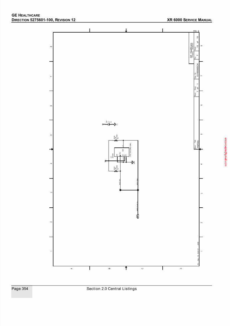
7/24/2019 GE XR6000 X-Ray - Service Manual
http://slidepdf.com/reader/full/ge-xr6000-x-ray-service-manual 354/421
GE HEALTHCARE
DIRECTION 5275601-100, REVISION 12 XR 6000 SERVICE MANUAL
Page 354 Section 2.0 Central Listings
F r i
D e c
1 5
1 5 : 4 1 : 4 1
2 0 0 6
1 5
o f
1 5
m e m o r y
5 1 7 6 5 5 6 S C H
1
o f
1
2
C 9 7
R 1 3 8
R 1 3 7
7
5
6 3 2 1
U 1 1
3 V 3
5 0 V
1 0 %
0 . 1 U
G N D
V C C = 3 V 3 ; G N D = G N D
G N D 3
V 3
0 . 1 2 5 W
1 0 K
P O 2_ S C L
3 2
1 %
1 0 K
1 %
0 . 1 2 5 W
2 4 C 2 5 6
P O 3_ S D A
A R M_ I O < 3 0 . . 0 >
C
o m p a n y
R e s t r i c t e d
8
6
5
R e v
B S i z e
1
6
C D B
2
A
5
7
8
4
3
S h e e t
3
2
1
4
B l o c k
S h e e t
G
E
H e a l t h c a r e
7
D w g
N o
B l o c k
P a t h
I O
S D A
S C L
W P
A 0
A 2
A 1

7/24/2019 GE XR6000 X-Ray - Service Manual
http://slidepdf.com/reader/full/ge-xr6000-x-ray-service-manual 355/421
GE HEALTHCARE
DIRECTION 5275601-100, REVISION 12 XR 6000 SERVICE MANUAL
Chapter 10 - Schematics Page 355
3.4 Jedi Generator TAV Interface Board
P O W E R S U
P P L Y I S
O L A T E D
5 V
1 2 V
T O
5 V
C H A N G
E T O
1 6 V
P O W E R G O O D
F r i
D e c
2 9
1 6 : 0 4 : 0 3
2 0 0 6
1
o f
4
j e d i_ t a v
5 1 8 2 2 8 5 S C H
1
o f
4
1
W A N
G Z Y
1
2 9 - D E C - 0 6
3 5 V
C 6
7 6
F
1
R 4
1 2
D S 1
T P 3
T P 4
C 8
C 5
R 3
C 2
C 1
2 1
1 2
1 4
2 8
1 7
1 6 1 3
2 7
2 6
U 1
T P 2
T P 1
D 2
C 9
L 1
D 1
C 7
R 1
R 2
C 4
C 3
4 3
2 1
F L 1
8 1
2
4 3
U 2
G N D
0 . 1 U
2 0 %
3 5 V
V A R I O U S
1 % 0 . 1 2 5 W
3 . 1 6 K
1 %
1 0 %
G R E E N
H L M P - 1 7 9 0
0 3 - J U L Y - 0 6
A
W A N
G Z Y
L S M 3 4 0 J
5 A
1 2 V
1 2 V_
I N
1 2 V_
G N D
6
3 V
F
A S T_
A C T I O N
0 . 4 7 U
1 0 %
1 6 V
R S 2 3 2_
V C C
T I N
R S 2 3 2_
G N D
T I N
4 7 U
1 0 %
1 U 2 5 V
1 0 K 0 . 1 2 5 W
D C R 0 1 0 5 0 5 U
5 V
1 6 V 1 0 %
0 . 4 7 U
V C C
3 5 V 1 0 %
1 0 U
G N D
1 A
2 0 0
O H M
Z J Y S 5 1 R 5 - 2 P
4 0 V
5 0 V 1 0 %
1 0 N
1 0 %
1 0 U
6 . 8 V
0 . 1 2 5 W
1 %
5 1 1
V C C
0 . 1 2 5 W
1 %
1 K
T I N
1 0 %
5 0 V
1 0 0 U
3 5 V
M M S Z 5 2 3 5 B
3 3 U 2 0 %
L M 2 6 7 6
T I N
C o m p a n y
R e s t r i c t e d
8
6
5
R E V 2 0 1 J u l y 0 4 D
R e v
B S i z e
1
6
C D B
2
A
5
7
8
A B C
4
3
S h e
e t
3
2
1
4
B l o c k
S h e e t
G E
H e a l t h c a r e
7
D w g
N o
B l o c k
P a t h
S Y N C I N
V S 2
V S 1
E R R O R_
N
V O U T
0 V O U T
E N A B L E
V R E C
0 V I N 2
0 V I N 1
D A T E
S I G N
O F F
R E V I S I O N
E C R / E C O
F E E D B A C K
O N_
O F F
S W I T_
O U T
B O O S T
I N P U T
G N D
T A B_
G N D
P

7/24/2019 GE XR6000 X-Ray - Service Manual
http://slidepdf.com/reader/full/ge-xr6000-x-ray-service-manual 356/421
GE HEALTHCARE
DIRECTION 5275601-100, REVISION 12 XR 6000 SERVICE MANUAL
Page 356 Section 2.0 Central Listings
R X
L E D
R S 4 8 5
-
R S 2 3 2
C O N V E R T O R
T X
L E D
W e d
S e p
1 3
1 4 : 2 9 : 5 6
2 0 0 6
2
o f
4
j e d i_ t a v
5 1 8 2 2 8 5 S C H
2
o f
4
1
C 3 2
C 3 0
C 3 1
C 2 9
6
2
8
1
5
4
U 6
6
2
8
1
5
4
U 5
R 6
R 8
3 7
1 5
1 3
1 1
9
8
1 0
1 4
1 2
1 6
1 5 6 2 4
U 3
1
2
D S 3
1
2
D S 2
R 1 3
R 1
4
C 1 5
7
1 1
1 2
5
6 1 0 9
U 4
R 1 8
R 1 1
R 5
C 1 4
R 7
R 1 7
R 1 6
1 5 3
4 1 3
1 4 2 1
U 4
C 1 0
C 1 2
C 1 1
C 1 3
6 5
1
2 4
3 7 8
U 7
0 . 1 2 5 W
R S 4 8 5_ R X
T X D
H C P L 0 7 2 0 - 0 6 0
R S 2 3 2_ G N D
0 . 1 2 5 W
1 %
H L M P - 1 7 1 9
R S 2 3 2_ G N D
R S 2 3 2_ V C C
0
2 0 K 0 . 1 2 5 W
R S 2 3 2_ R X
T X D
R S 2 3 2_ T X
R X D
1
1 0 %
+ 0 . 0 5
H C P L 0 7 2 0 - 0 6 0
0 . 1 U
5 0 V
R X D
R S 4 8 5_ T X
V C C
G N D
1 0 %
5 0 V
0 . 1 U
1 %
5 1 1
R S 4 8 5_ R X
V C C
0 . 1 %
C O N S O L E_ T X -
C O N S O L E_ T X +
0 . 1 W
V C C
4
1 %
0 . 1 2 5 W
R S 2 3 2_ V C C
V C C = V C C ; G N D = G N D
1 %
0 . 1 2 5 W
R S 2 3 2_ R X
2
1 %
5 0 V
0 . 1 U
5 0 V
R S 2 3 2 < 1 . . 2 >
0 . 1 U
M A X 3 2 2 1 E
1 0 %
R S 4 8 5 < 1 . . 4 >
1 1 0
0 . 1 %
0 . 1 W
1 0 %
V C C
1 %
7 4 H C 1 2 3
1 0 %
2 0 K
1 K
1 K
V C C
5 1 1
1 %
0 . 1 2 5 W
H L M P - 1 7 1 9
Y E L L O W
1 U 1 6 V
Y E L L O W
1 0 %
5 0 V
0 . 1 U
V C C
1
2
M A X 4 8 8 E
1 1 0
3
C O N S O L
E_ R X +
C O N S O L
E_ R X -
2 0 K
7 4 H C 1 2 3
V C C = V C C ; G N D = G N D
0 . 1 2 5 W
1 0 %
1 U 1 6 V
0 . 1 2 5 W
1 0 %
R S 2 3 2_ V C C
1 0 %
5 0 V
0 . 1 U
0 . 1 U
5 0 V 1 0 %
R S 2 3 2_ G N D
R S 2 3 2_ G N D
R S 2 3 2_ V C C
G N D
V C C
5 0 V
0 . 1 U
G N D
C o m p a n y
R e s t r i c t e d
8
6
5
R E V 2 0 1 J u l y 0 4 D
R e v
B S i z e
1
6
C D B
2
A
5
7
8
A B C
4
3
S h e e t
3
2
1
4
B l o c k
S h e e t
G E
H e a l t h c a r e
7
D w g
N o
B l o c k
P a t h
V I
G N D 1
G N D 2
V D D 1
V O V
D D 2
V I G
N D 1
G N D 2
V D D 1
V O
V D D 2
F O R C E O N
E N_
N
R 1 I N
T 1 I N
C 2 N
C 2 P
C 1 N
C 1 P
V N
V P
V C C
G N D
F O R C E O F F_ N
I N V A L I D_ N
R 1 O U T
T 1 O U T
C E X T
Q
Q_
N
R D
B A_
N
R E X T_ C E X T
V C C
B D I
Y Z
A
R O
G N D
C E X T
Q
Q_
N
R D
B A_
N
R E X T_ C E X T
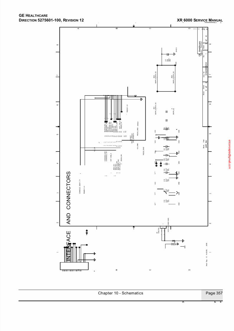
7/24/2019 GE XR6000 X-Ray - Service Manual
http://slidepdf.com/reader/full/ge-xr6000-x-ray-service-manual 357/421
GE HEALTHCARE
DIRECTION 5275601-100, REVISION 12 XR 6000 SERVICE MANUAL
Chapter 10 - Schematics Page 357
I N T E R F A C E
A N D
C O N N E C T O R S
W e d
S e p
1 3
1 4 : 2 9 : 5 6
2 0 0 6
3
o f
4
j e d i_ t a v
5 1 8 2 2 8 5 S C H
3
o f
4
1
G 2
G 1
9 8 7 6 5 4 3
2 5
2 4
2 3
2 2
2 1
2 0
2
1 9
1 8
1 7
1 6
1 5
1 4
1 3
1 2
1 1
1 0 1
J 1
C 2 3
C 2 4
R 1 9
3
2 1
U 8
C 2 2
C 2 1
C 1 7
C 2 0
C 1 9
C 1 8
C 1 6
1 M H 4
1 M H 2
1 M H 3
1 M H 1
R S 4 8 5 < 1 . . 4 >
C O N S O L E_ J E D I < 1 . . 7 >
J E D I_ R X +
E X T_ C A N_ L
J E D I_ P R E P_ S W
J E D I_ O N_ S W
J E D I_ T X +
E X T_ C A N_ H
R S 2 3 2_ R X
C O N S O L E_ T X +
C O N S O L E_ R X +
R S 2 3 2 < 1 . . 2 >
E X T_ C A N_ H
J E D I_ E X P_ S W
J E D I_ R X -
E X T_ C A N_ L
O N_
S W
J E D I_ T X -
C O N S O L E_ T X -
C O N S O L E_ R X -
P R E P A R E_ S W
E X P O S U R E_ S W
R S 2 3 2_ T X
2
5 7 4
1
1
2
2 1
R S 2 3 2_ G N D
1 2 V_
G N D
R S 2 3 2_ G N D
1 2 V_
I N
S H I E L D
1
1 6
4
5 4
3 4 3
3 2
S O C K E T
R I G H T_ A N G L E
S T D_ D E N S I T Y
V C C
V C C
V C C
G N D
2 5 0 V
2 0 %
2 2 N
S H I E L D
M H P 4_ 5 0 T B 1 0_ 0 0
M H P 4_ 5 0 T B 1 0_ 0 0
G N D
G N D
G N D
0 . 1 U
1 0 %
5 0 V
0 . 1 U
1 0 %
5 0 V
V C C
V C C
0 . 1 U
1 0 %
5 0 V
V C C
G
N D
G N D
G N D
0 . 1 U
1 0 %
5 0 V
0 . 1 U
1 0 %
5 0 V
V
C C
0 . 1 U
1 0 %
5 0 V
G N D
G N D
5 0 V 1 0 %
0 . 1 U
5 0 V 1 0 %
0 . 1 U
M H P 4_ 5 0 T B 1 0_ 0 0
2 0 K
1 %
0 . 1 2 5 W
G N D
7 4 A
C T 0 0
V
C C = V C C ; G N D = G N D
M H P 4_ 5 0 T B 1 0_ 0 0
V C C
C o m p a n y
R e s t r i c t e d
8
6
5
R E V 2 0 1 J u l y 0 4 D
R e v
B S i z e
1
6
C D B
2
A
5
7
8
A B C
4
3
S h e e t
3
2
1
4
B l o c k
S h e e t
G E
H e a l t h c a r e
7
D w g
N o
B l o c k
P a t h
2 3 1 3
4
1 7
9 1 0
1 5 7 6 8 1 2
1 1
1 4
1 6
1 5
1 9
1 8
2 0
2 2
G 1 G 2
2 5
2 4
2 3
2 1
Y
B A
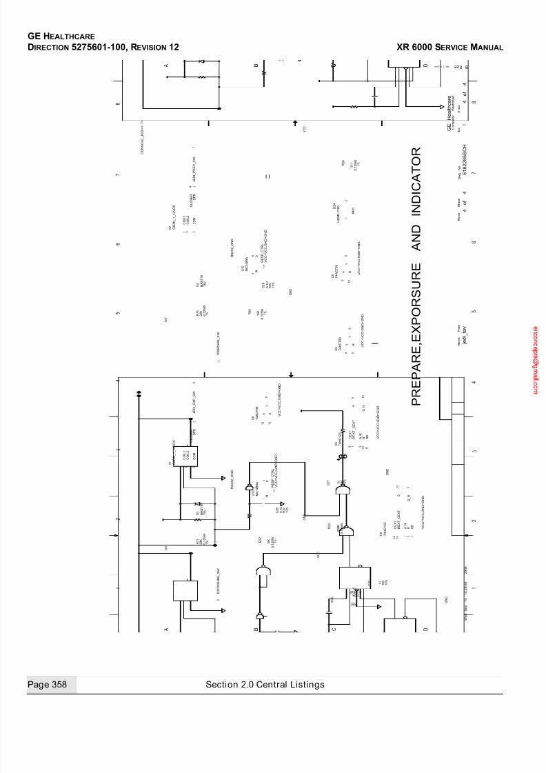
7/24/2019 GE XR6000 X-Ray - Service Manual
http://slidepdf.com/reader/full/ge-xr6000-x-ray-service-manual 358/421
GE HEALTHCARE
DIRECTION 5275601-100, REVISION 12 XR 6000 SERVICE MANUAL
Page 358 Section 2.0 Central Listings
P
R E P A R E , E X P O R S U R E
A N D
I N D I C A T O R
W e d
S e p
1 3
1 4 : 2 9 : 5 6
2 0 0 6
4
o f
4
j e d i_ t a v
5 1 8 2 2 8 5 S C H
4
o f
4
1
C 2 7
C 2 5
R 2 0
R 2 3
R 2 4
C 2 8
5
6
4 U
1 0
R 2 5
D 4
3
2 5 1
4
K 2
3
2 5 1
4
K 1
R 2 6
1
2
D S 4
6
5 4
U 8
1 1
1 3
1 2
U 8
8
1 0 9
U 8
R
2 2
C 2 6
R 2
1
2
3
1
U 1 0
D 3
7 1 1
1 2
5
6 1 0 9
U 9
1 5 3
4 1 3
1 4 2 1
U 9
1 U 1 6 V 1 0 %
1 6 V
1 U
1 0 %
1 %
3 9 2 K 0 . 1 2 5 W
V C C
1 %
2 0 0 K
0 . 1 2 5 W
1 %
M C 1 4 8 9 A
V C C = V C C ; G N D = G N D
V C C = V C C ; G N D = G N D
7 4 A C T 0 0
V C C = V C C ; G N D = G N D
7 4 A C T 0 0
V C C = V C C ; G N D = G N D
M
C 1 4 8 9 A
E X P O S U R E_ S W
7 4 A C T 0 0
P R E P A R E_ S W
0 . 1 2 5 W
1 5 K
R E D
0 . 1 2 5 W
1 5 K
H L M P - 1 7 0 0
0 . 1 U
V C C = V C C ; G N D = G N D
B A S 1 1 6
7 5 V
R S 2 3 2_ G N D
J E D I_
E X P_ S W
1 0 %
5 0 V
0 . 1 2 5 W
2 0 K
G N D
1 %
2 0 K
0 . 1
2 5 W
G 6 R N_ 1_ 1 2 V D C
J E D I_ P R E P_ S W
2
6
7
3
G 6 R N_ 1_ 1 2 V D C
R S 2 3 2_ G N D
G N D
7 4 H C 1 2 3
C O N S O L E_ J E D I < 1 . . 7 >
1 %
7 5 V
B A S 1 1 6
V C C
G N D
5 0 V 1 0 %
0 . 1 U
0 . 1 2 5
W 1 %
G N D
V C C = V C C ; G N D = G N D
7 4 H C 1 2 3
1 2 V
5 1 1
1 %
V C C
1 2 V
V C C = V C C ; G N D = G N D
C o m p a n y
R e s t r i c t e d
8
6
5
R E V 2 0 1 J u l y 0 4 D
R e v
B S i z e
1
6
C D B
2
A
5
7
8
A B C
4
3
S h e e t
3
2
1
4
B l o c k
S h e e t
G E
H e a l t h c a r e
7
D w g
N o
B l o c k
P a t h
C O I L 1
C O I L 2
O P N
C L O S E D
C O M
C O I L 1
C O I L 2
O P N
C L O S E D
C O M
Y
B A
Y
B A
Y
B A
I N
O
R E S P_ C T R L
C E X T
Q
Q_ N
R D
B A_
N
R E X T_ C E X T
I N
O
R E S P_ C T R L
C E X T
Q
Q_
N
R D
B A_
N
R E X T_ C E X T
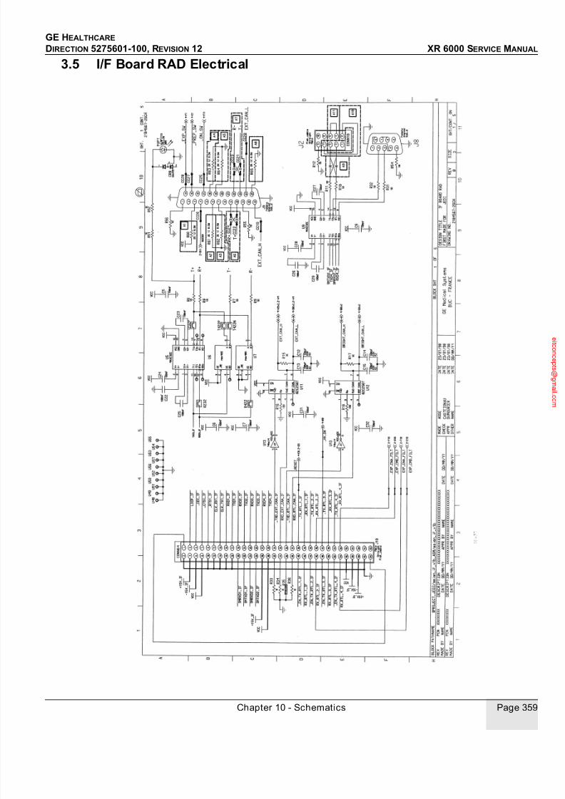
7/24/2019 GE XR6000 X-Ray - Service Manual
http://slidepdf.com/reader/full/ge-xr6000-x-ray-service-manual 359/421
GE HEALTHCARE
DIRECTION 5275601-100, REVISION 12 XR 6000 SERVICE MANUAL
Chapter 10 - Schematics Page 359
3.5 I/F Board RAD Electrical

7/24/2019 GE XR6000 X-Ray - Service Manual
http://slidepdf.com/reader/full/ge-xr6000-x-ray-service-manual 360/421
GE HEALTHCARE
DIRECTION 5275601-100, REVISION 12 XR 6000 SERVICE MANUAL
Page 360 Section 2.0 Central Listings

7/24/2019 GE XR6000 X-Ray - Service Manual
http://slidepdf.com/reader/full/ge-xr6000-x-ray-service-manual 361/421
GE HEALTHCARE
DIRECTION 5275601-100, REVISION 12 XR 6000 SERVICE MANUAL
Chapter 10 - Schematics Page 361

7/24/2019 GE XR6000 X-Ray - Service Manual
http://slidepdf.com/reader/full/ge-xr6000-x-ray-service-manual 362/421
GE HEALTHCARE
DIRECTION 5275601-100, REVISION 12 XR 6000 SERVICE MANUAL
Page 362 Section 2.0 Central Listings

7/24/2019 GE XR6000 X-Ray - Service Manual
http://slidepdf.com/reader/full/ge-xr6000-x-ray-service-manual 363/421
GE HEALTHCARE
DIRECTION 5275601-100, REVISION 12 XR 6000 SERVICE MANUAL
Chapter 10 - Schematics Page 363
3.6 I/F Board RAD V2 Electrical

7/24/2019 GE XR6000 X-Ray - Service Manual
http://slidepdf.com/reader/full/ge-xr6000-x-ray-service-manual 364/421
GE HEALTHCARE
DIRECTION 5275601-100, REVISION 12 XR 6000 SERVICE MANUAL
Page 364 Section 2.0 Central Listings
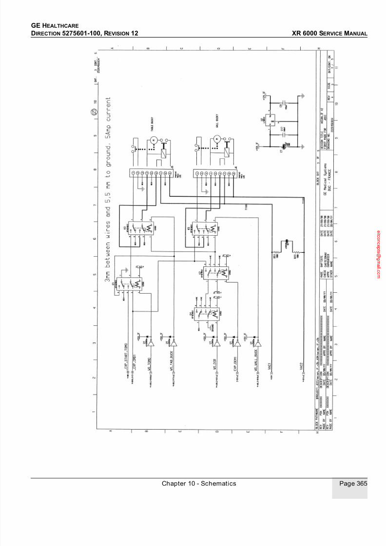
7/24/2019 GE XR6000 X-Ray - Service Manual
http://slidepdf.com/reader/full/ge-xr6000-x-ray-service-manual 365/421
GE HEALTHCARE
DIRECTION 5275601-100, REVISION 12 XR 6000 SERVICE MANUAL
Chapter 10 - Schematics Page 365

7/24/2019 GE XR6000 X-Ray - Service Manual
http://slidepdf.com/reader/full/ge-xr6000-x-ray-service-manual 366/421
GE HEALTHCARE
DIRECTION 5275601-100, REVISION 12 XR 6000 SERVICE MANUAL
Page 366 Section 2.0 Central Listings

7/24/2019 GE XR6000 X-Ray - Service Manual
http://slidepdf.com/reader/full/ge-xr6000-x-ray-service-manual 367/421
GE HEALTHCARE
DIRECTION 5275601-100, REVISION 12 XR 6000 SERVICE MANUAL
Chapter 10 - Schematics Page 367
3.7 Rotor board

7/24/2019 GE XR6000 X-Ray - Service Manual
http://slidepdf.com/reader/full/ge-xr6000-x-ray-service-manual 368/421
GE HEALTHCARE
DIRECTION 5275601-100, REVISION 12 XR 6000 SERVICE MANUAL
Page 368 Section 2.0 Central Listings

7/24/2019 GE XR6000 X-Ray - Service Manual
http://slidepdf.com/reader/full/ge-xr6000-x-ray-service-manual 369/421
GE HEALTHCARE
DIRECTION 5275601-100, REVISION 12 XR 6000 SERVICE MANUAL
Chapter 10 - Schematics Page 369

7/24/2019 GE XR6000 X-Ray - Service Manual
http://slidepdf.com/reader/full/ge-xr6000-x-ray-service-manual 370/421
GE HEALTHCARE
DIRECTION 5275601-100, REVISION 12 XR 6000 SERVICE MANUAL
Page 370 Section 2.0 Central Listings

7/24/2019 GE XR6000 X-Ray - Service Manual
http://slidepdf.com/reader/full/ge-xr6000-x-ray-service-manual 371/421
GE HEALTHCARE
DIRECTION 5275601-100, REVISION 12 XR 6000 SERVICE MANUAL
Chapter 10 - Schematics Page 371

7/24/2019 GE XR6000 X-Ray - Service Manual
http://slidepdf.com/reader/full/ge-xr6000-x-ray-service-manual 372/421
GE HEALTHCARE
DIRECTION 5275601-100, REVISION 12 XR 6000 SERVICE MANUAL
Page 372 Section 2.0 Central Listings
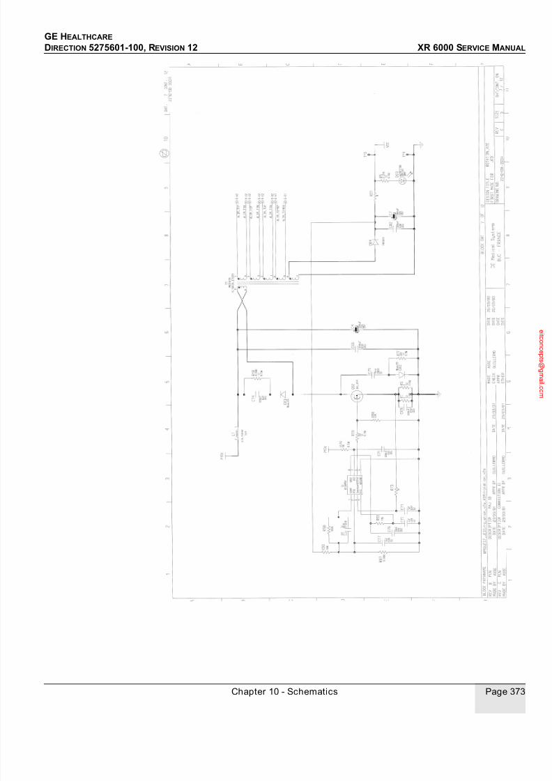
7/24/2019 GE XR6000 X-Ray - Service Manual
http://slidepdf.com/reader/full/ge-xr6000-x-ray-service-manual 373/421
GE HEALTHCARE
DIRECTION 5275601-100, REVISION 12 XR 6000 SERVICE MANUAL
Chapter 10 - Schematics Page 373

7/24/2019 GE XR6000 X-Ray - Service Manual
http://slidepdf.com/reader/full/ge-xr6000-x-ray-service-manual 374/421
GE HEALTHCARE
DIRECTION 5275601-100, REVISION 12 XR 6000 SERVICE MANUAL
Page 374 Section 2.0 Central Listings

7/24/2019 GE XR6000 X-Ray - Service Manual
http://slidepdf.com/reader/full/ge-xr6000-x-ray-service-manual 375/421
GE HEALTHCARE
DIRECTION 5275601-100, REVISION 12 XR 6000 SERVICE MANUAL
Chapter 10 - Schematics Page 375
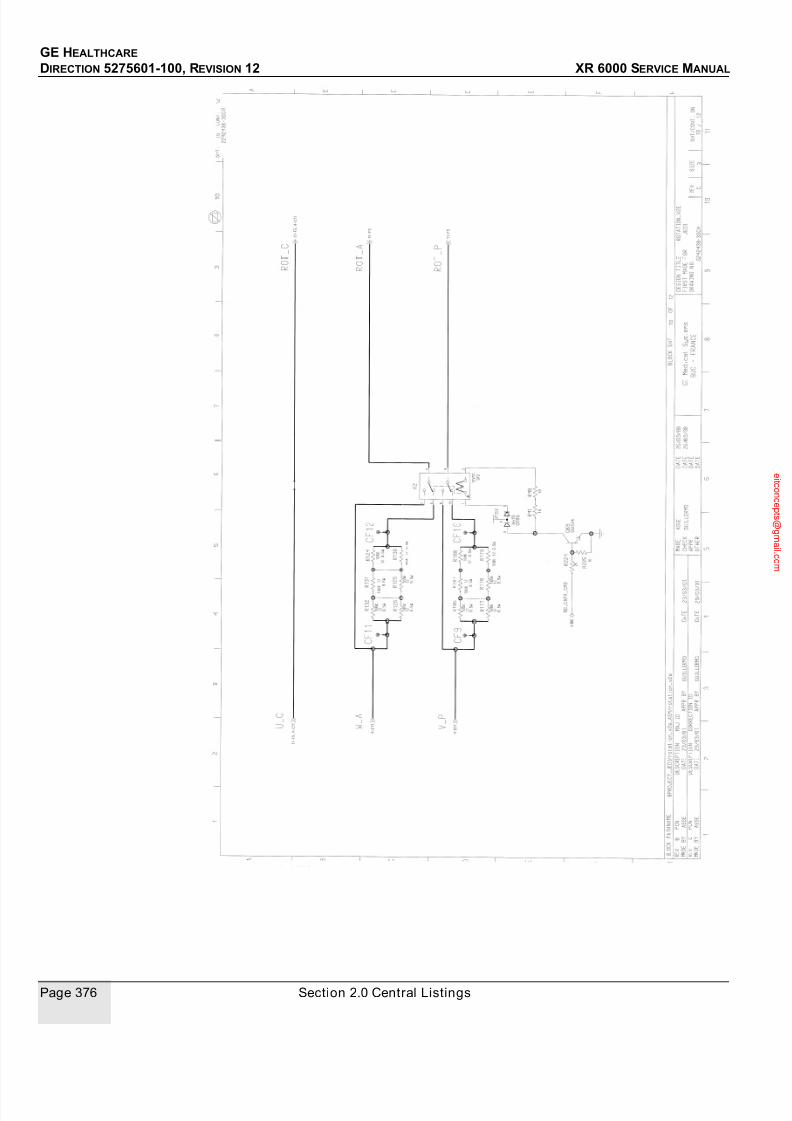
7/24/2019 GE XR6000 X-Ray - Service Manual
http://slidepdf.com/reader/full/ge-xr6000-x-ray-service-manual 376/421
GE HEALTHCARE
DIRECTION 5275601-100, REVISION 12 XR 6000 SERVICE MANUAL
Page 376 Section 2.0 Central Listings
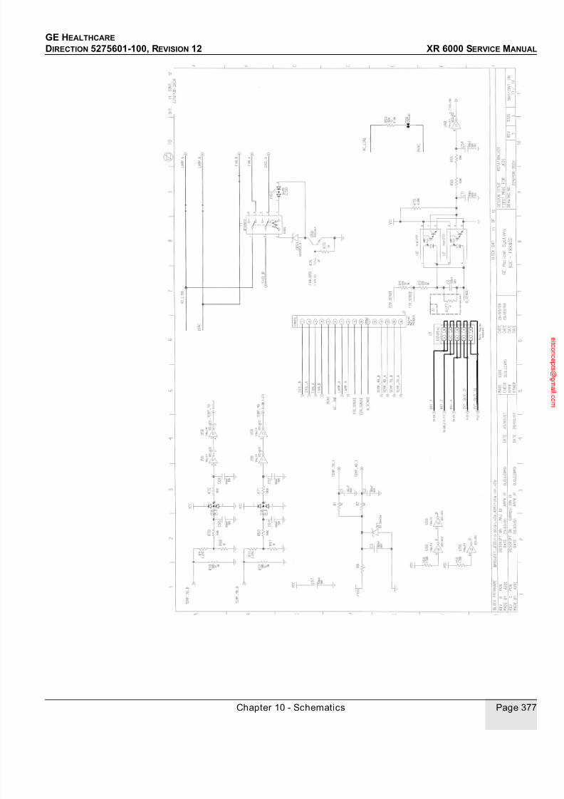
7/24/2019 GE XR6000 X-Ray - Service Manual
http://slidepdf.com/reader/full/ge-xr6000-x-ray-service-manual 377/421
GE HEALTHCARE
DIRECTION 5275601-100, REVISION 12 XR 6000 SERVICE MANUAL
Chapter 10 - Schematics Page 377

7/24/2019 GE XR6000 X-Ray - Service Manual
http://slidepdf.com/reader/full/ge-xr6000-x-ray-service-manual 378/421
GE HEALTHCARE
DIRECTION 5275601-100, REVISION 12 XR 6000 SERVICE MANUAL
Page 378 Section 2.0 Central Listings
3.8 Heater board

7/24/2019 GE XR6000 X-Ray - Service Manual
http://slidepdf.com/reader/full/ge-xr6000-x-ray-service-manual 379/421
GE HEALTHCARE
DIRECTION 5275601-100, REVISION 12 XR 6000 SERVICE MANUAL
Chapter 10 - Schematics Page 379
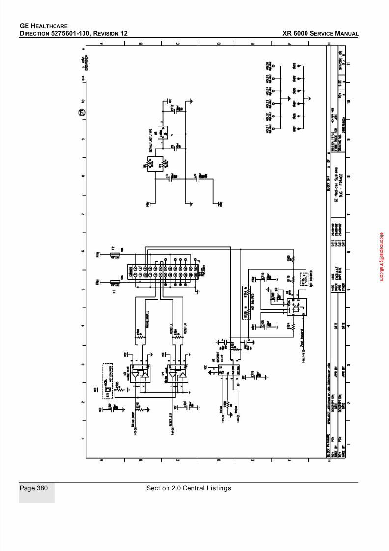
7/24/2019 GE XR6000 X-Ray - Service Manual
http://slidepdf.com/reader/full/ge-xr6000-x-ray-service-manual 380/421
GE HEALTHCARE
DIRECTION 5275601-100, REVISION 12 XR 6000 SERVICE MANUAL
Page 380 Section 2.0 Central Listings

7/24/2019 GE XR6000 X-Ray - Service Manual
http://slidepdf.com/reader/full/ge-xr6000-x-ray-service-manual 381/421
GE HEALTHCARE
DIRECTION 5275601-100, REVISION 12 XR 6000 SERVICE MANUAL
Chapter 10 - Schematics Page 381

7/24/2019 GE XR6000 X-Ray - Service Manual
http://slidepdf.com/reader/full/ge-xr6000-x-ray-service-manual 382/421
GE HEALTHCARE
DIRECTION 5275601-100, REVISION 12 XR 6000 SERVICE MANUAL
Page 382 Section 2.0 Central Listings

7/24/2019 GE XR6000 X-Ray - Service Manual
http://slidepdf.com/reader/full/ge-xr6000-x-ray-service-manual 383/421
GE HEALTHCARE
DIRECTION 5275601-100, REVISION 12 XR 6000 SERVICE MANUAL
Chapter 10 - Schematics Page 383

7/24/2019 GE XR6000 X-Ray - Service Manual
http://slidepdf.com/reader/full/ge-xr6000-x-ray-service-manual 384/421
GE HEALTHCARE
DIRECTION 5275601-100, REVISION 12 XR 6000 SERVICE MANUAL
Page 384 Section 2.0 Central Listings

7/24/2019 GE XR6000 X-Ray - Service Manual
http://slidepdf.com/reader/full/ge-xr6000-x-ray-service-manual 385/421

7/24/2019 GE XR6000 X-Ray - Service Manual
http://slidepdf.com/reader/full/ge-xr6000-x-ray-service-manual 386/421
GE HEALTHCARE
DIRECTION 5275601-100, REVISION 12 XR 6000 SERVICE MANUAL
Page 386 Section 2.0 Central Listings
O P T I M I Z E
F O R
1 0 0 M A
M o n
M a y
1 6
1 2 : 1 7 : 5 5
2 0 0 5
2
o f 2
L V P S_
T R I_ V 5
2 2 1 2 1 6 6 - 5 S C H
2
o f
2
1
0 . 5 A M P
L O W_
V O L T A G E
F
O R W A R D_
M E A S U R E
0 . 2 5 A M P
L O W_
V O L T A G E
L O W_
V O L T A G E
0 . 2 5 A M P
0 . 2 5 A M P
L O W_
V O L T A G E
L O W_
V O L T A G E
0 . 2 5 A M P
L O W_
V O L T A
G E
1 A M P
0 . 2 5 A M P
L O W_
V O L T A G E
L O W_
V O L T A G E
0 . 2 5 A M P
L O W_
V O L T A G E
L O W_
V O L T A G E
0 . 2 5 A M P
0 . 2 5 A M P
L O W_
V O L T A G E
0 . 2 5 A M P
L O W_
V O L T A G
E
0 . 2 5 A M P
0 . 2 5 A M P
L O W_
V O L T A G E
_ M A I N S_
D R O P
L O W_
V O L T A G E
0 . 2 5 A M P
0 . 7 5 A M P
L O W_
V O L T A G E
0 . 2 5 A M P
L O W_
V O L T A G E
0 . 2 5 A M P
L O W
_ V O L T A G E
0 . 2 5 A M P
L O W_
V O L T A G E
L O W_
V O L T A G E
L O W_
V O L T A G E
0 . 2 5 A M P
2 1
3
C R 6
7 5 V
B A W 5 6
C 1 0
1 0 %
5 0 V
0 . 4 7 U
R 1 9
0 . 1 W
1 %
1 K R
1 7
0 . 1 W
1 K
1 % R
1 6
0 . 1 W
1 %
2 K R
1 8
2 K 0 . 1 W
1 %
R 1
5 %
1 0 1 W
P 1 5 V
C 2 2
0 . 4 7 U
1 0 %
5 0 V
3
1
4
U 4
5 V
M C 7 8 M 0 5 C D T
V C C
C 1 7
1 0 %
5 0 V
0 . 1 U
C 1 5
0 . 1 U
1 0 %
5 0 V
R 1 5
0 . 1 W
2 0 K
1 %
8
7
4
2 3
1
6
5 U 3 L M 3 1 1
P 1 5 V
V C C
R 1
1
0 . 1 W 1 % 1
0 K
C 1 4
0 . 1 U
5 0 V 1 0 %
M 1
5 V
M 1 5 V
R 8
1 0 0 K
0 . 1 W 1 %
R 6
1 % 1
0 K
0 . 1 W
V C C
1 2
D S 1
I S L O C A L P A R T = T R U E
H L M P
1 7 0 9
R E D
R 9
1 %
2 K 0 . 1 W
V C C
C 1 1
0 . 1 U
5 0 V 1 0 %
P 1 5 V
C 2 1
5 0 V
0 . 1 U
1 0 %
V C C
1
2 4 3 7 6
U 2
M A X 4 8 5
V C C = V C C ; G N D = G N D_
C H A S S I S
C 9
5 0 V
0 . 1 U
1 0 %
R 2
1 %
1 K 0 . 1 W
P O W E R_
M 1 5 V
9
8
7
6
5
4
3
2 6
2 5
2 4
2 3
2 2
2 1
2 0
2
1 9
1 8
1 7
1 6
1 5
1 4
1 3
1 2
1 1
1 0
1
J 1
S T R A I G H T
P I N
R I B B O N_
C A B L E_
S T A N
D A R D P
O W E R_
P 1 5 V
V C C
C o m p a n y
R e s t r i c t e d
8
6
5
R E V 2 0 1 J u l y 0 4 D
R e v
B S i z e
1
6
C D B
2
A
5
7
8
A B C
4
3
S h e e t
3
2
1
4
B l o c k
S h e e t
G E
H e a l t h c a r e
7
D w g
N o
B l o c k
P a t h
R O
A B D E
D I
R E_
N
A
K 2
K 1
G N D
V O U T
V I N
2 6
2 4
3 1 7 9 1 1
1 9
1 7
2 4 6 8
1 2
1 0
1 4 1 6 1 8
2 2
2 0
5 1 3 1 5
2 1 2 3 2 5
V N
B A L _ S T R B A L
G N D
V O U T
V P
S t a t e : R E L E A S E - D o c u m e n t i s r e l e a s e d a n d u n d e r f o r m a l C h a n g e C o n t r o l . C h a n g e s a r e s u b j e c t t o t h e E C R / E C O P r o c e s s . S e e t h e G E M S e P D M S y s t e m t o d e t e r m i n e t h e s t a t u s o f t h i s d o c u m e n t .
A p p r o v e d D
o c u m e n t - 2 2 1 2 1 6 6 - 5 S C H_
r 1 . p
d f P a g e 3 o f 3

7/24/2019 GE XR6000 X-Ray - Service Manual
http://slidepdf.com/reader/full/ge-xr6000-x-ray-service-manual 387/421
GE HEALTHCARE
DIRECTION 5275601-100, REVISION 12 XR 6000 SERVICE MANUAL
Chapter 10 - Schematics Page 387
3.10 Inverter

7/24/2019 GE XR6000 X-Ray - Service Manual
http://slidepdf.com/reader/full/ge-xr6000-x-ray-service-manual 388/421
GE HEALTHCARE
DIRECTION 5275601-100, REVISION 12 XR 6000 SERVICE MANUAL
Page 388 Section 2.0 Central Listings
3.11 Gate cmd

7/24/2019 GE XR6000 X-Ray - Service Manual
http://slidepdf.com/reader/full/ge-xr6000-x-ray-service-manual 389/421
GE HEALTHCARE
DIRECTION 5275601-100, REVISION 12 XR 6000 SERVICE MANUAL
Chapter 10 - Schematics Page 389

7/24/2019 GE XR6000 X-Ray - Service Manual
http://slidepdf.com/reader/full/ge-xr6000-x-ray-service-manual 390/421
GE HEALTHCARE
DIRECTION 5275601-100, REVISION 12 XR 6000 SERVICE MANUAL
Page 390 Section 2.0 Central Listings
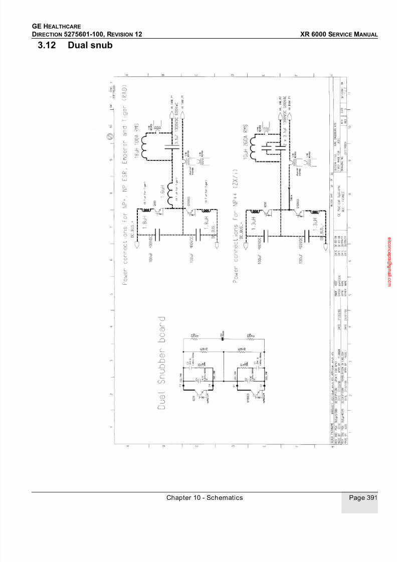
7/24/2019 GE XR6000 X-Ray - Service Manual
http://slidepdf.com/reader/full/ge-xr6000-x-ray-service-manual 391/421
GE HEALTHCARE
DIRECTION 5275601-100, REVISION 12 XR 6000 SERVICE MANUAL
Chapter 10 - Schematics Page 391
3.12 Dual snub

7/24/2019 GE XR6000 X-Ray - Service Manual
http://slidepdf.com/reader/full/ge-xr6000-x-ray-service-manual 392/421
GE HEALTHCARE
DIRECTION 5275601-100, REVISION 12 XR 6000 SERVICE MANUAL
Page 392 Section 2.0 Central Listings
3.13 AC/DC board

7/24/2019 GE XR6000 X-Ray - Service Manual
http://slidepdf.com/reader/full/ge-xr6000-x-ray-service-manual 393/421
GE HEALTHCARE
DIRECTION 5275601-100, REVISION 12 XR 6000 SERVICE MANUAL
Chapter 10 - Schematics Page 393
3.14 AEC board
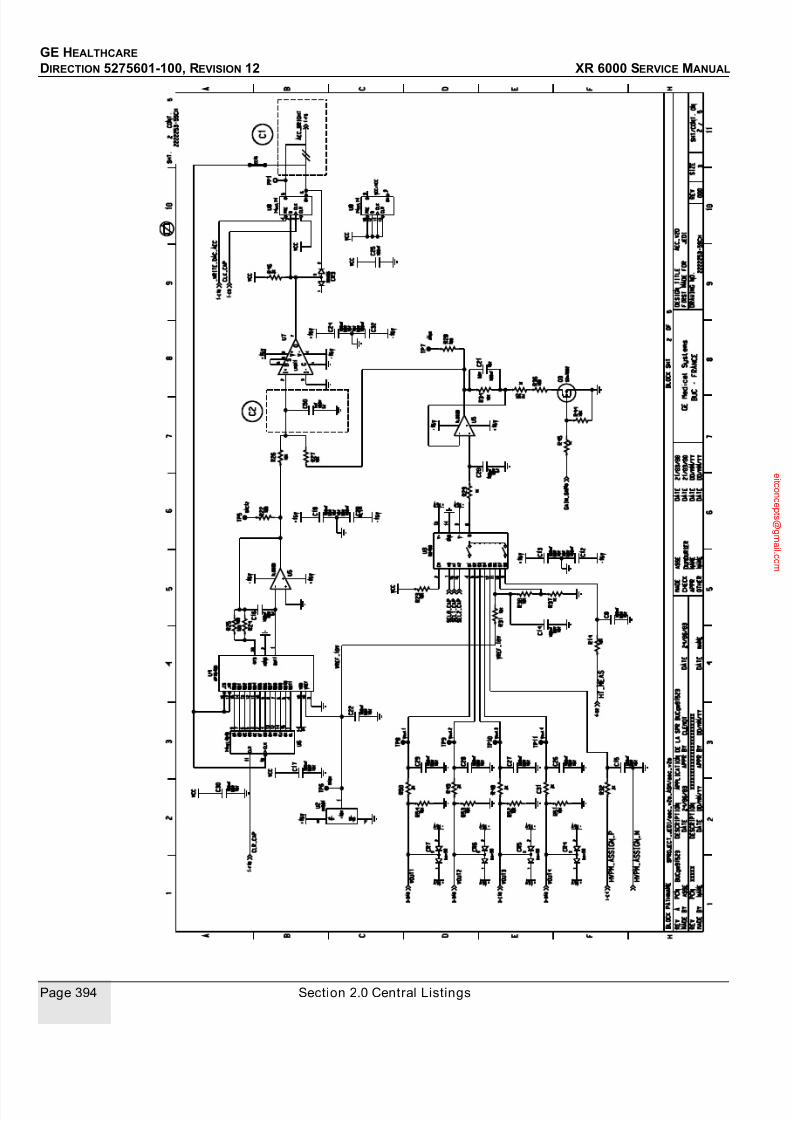
7/24/2019 GE XR6000 X-Ray - Service Manual
http://slidepdf.com/reader/full/ge-xr6000-x-ray-service-manual 394/421
GE HEALTHCARE
DIRECTION 5275601-100, REVISION 12 XR 6000 SERVICE MANUAL
Page 394 Section 2.0 Central Listings
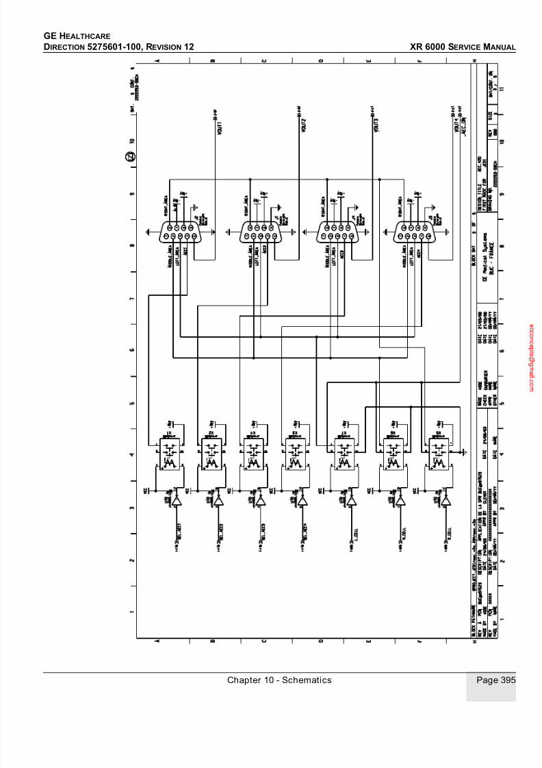
7/24/2019 GE XR6000 X-Ray - Service Manual
http://slidepdf.com/reader/full/ge-xr6000-x-ray-service-manual 395/421
GE HEALTHCARE
DIRECTION 5275601-100, REVISION 12 XR 6000 SERVICE MANUAL
Chapter 10 - Schematics Page 395
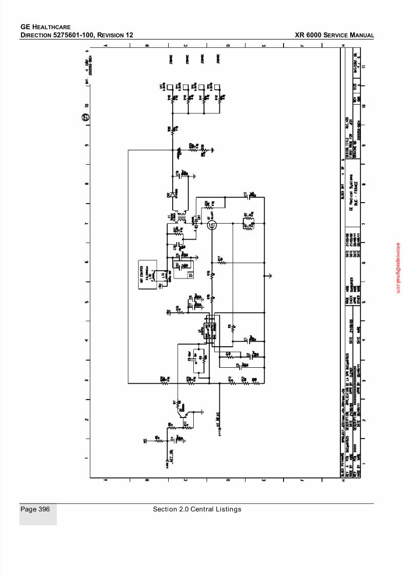
7/24/2019 GE XR6000 X-Ray - Service Manual
http://slidepdf.com/reader/full/ge-xr6000-x-ray-service-manual 396/421
GE HEALTHCARE
DIRECTION 5275601-100, REVISION 12 XR 6000 SERVICE MANUAL
Page 396 Section 2.0 Central Listings

7/24/2019 GE XR6000 X-Ray - Service Manual
http://slidepdf.com/reader/full/ge-xr6000-x-ray-service-manual 397/421
GE HEALTHCARE
DIRECTION 5275601-100, REVISION 12 XR 6000 SERVICE MANUAL
Chapter 10 - Schematics Page 397
3.15 Rad IF
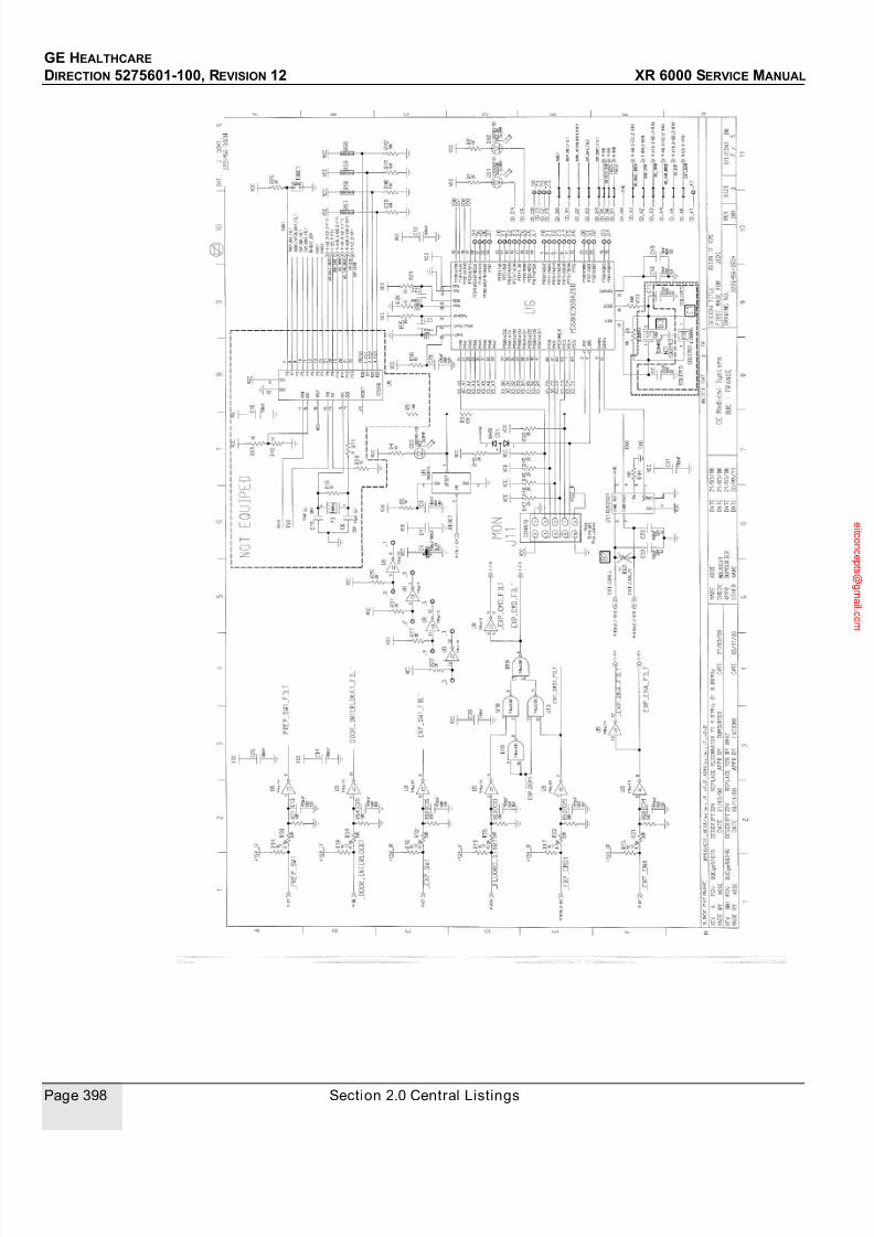
7/24/2019 GE XR6000 X-Ray - Service Manual
http://slidepdf.com/reader/full/ge-xr6000-x-ray-service-manual 398/421
GE HEALTHCARE
DIRECTION 5275601-100, REVISION 12 XR 6000 SERVICE MANUAL
Page 398 Section 2.0 Central Listings

7/24/2019 GE XR6000 X-Ray - Service Manual
http://slidepdf.com/reader/full/ge-xr6000-x-ray-service-manual 399/421
GE HEALTHCARE
DIRECTION 5275601-100, REVISION 12 XR 6000 SERVICE MANUAL
Chapter 10 - Schematics Page 399
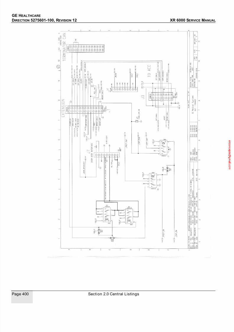
7/24/2019 GE XR6000 X-Ray - Service Manual
http://slidepdf.com/reader/full/ge-xr6000-x-ray-service-manual 400/421
GE HEALTHCARE
DIRECTION 5275601-100, REVISION 12 XR 6000 SERVICE MANUAL
Page 400 Section 2.0 Central Listings

7/24/2019 GE XR6000 X-Ray - Service Manual
http://slidepdf.com/reader/full/ge-xr6000-x-ray-service-manual 401/421
GE HEALTHCARE
DIRECTION 5275601-100, REVISION 12 XR 6000 SERVICE MANUAL
Chapter 11 - MIS Chart Page 401
Chapter 11 - MIS Chart
Section 1.0
ScopeThis section provides detailed information about each MIS run in the form of individual MIS cable
charts.
Each of the following charts defines a single interconnection in the system. The charts are arranged
in the order, according to MIS numbers. In some cases, a particular MIS number is repeated, except
for a letter added at the end. Such a set of charts use the same cable, and carry essentially the
same signals, however the applications for each chart is different - the point of connection is
different (at one or both ends) for each chart in the set.
Section 2.0 How to Use
Each MIS cable shown on the MIS map has its own MIS chart. Each chart identifies all signals
present on the cable, and the specific pins associated with each signal. See Figure 11-1 for an
example.
Figure 11-1 MIS Chart Example

7/24/2019 GE XR6000 X-Ray - Service Manual
http://slidepdf.com/reader/full/ge-xr6000-x-ray-service-manual 402/421
GE HEALTHCARE
DIRECTION 5275601-100, REVISION 12 XR 6000 SERVICE MANUAL
Page 402 Section 3.0 MIS Charts
Section 3.0 MIS Charts
3.1 System Console
3.1.1 J1 Handswitch Interface, 5184620
3.1.2 J2 FW Download Serial Port, 5194292
Handswitch System Console
1
Handswitch J1
1
2 2
3 3
4 4
COM
PREP
COM
EXP
System Console Service Laptop
1
J2 Serial Port
2 to console
3 from console
4
Receive Data
Transmit Data
5 GNDSignal Ground

7/24/2019 GE XR6000 X-Ray - Service Manual
http://slidepdf.com/reader/full/ge-xr6000-x-ray-service-manual 403/421
GE HEALTHCARE
DIRECTION 5275601-100, REVISION 12 XR 6000 SERVICE MANUAL
Chapter 11 - MIS Chart Page 403
3.1.3 J3 Power and RTL Interface, 5183903
System Console Download Tool
1
J2 Serial Port
2 to console
3 from console
4
Receive Data
Transmit Data
5 GNDSignal Ground
6
7 from consoleRequest to Send
from console
Data Terminal Ready
PDU System Console
1
TM3 J3
2 2 Console Power Input
3 3 Console Power Input
4
GND
GND
5 5Power Issue A
6
7 7 RTL (0-DC24V; Active: 0V)PSW
4E
DC24V1 Console Power Input
Power Issue B6

7/24/2019 GE XR6000 X-Ray - Service Manual
http://slidepdf.com/reader/full/ge-xr6000-x-ray-service-manual 404/421
GE HEALTHCARE
DIRECTION 5275601-100, REVISION 12 XR 6000 SERVICE MANUAL
Page 404 Section 3.0 MIS Charts
3.1.4 J4 Generator Interface, 5182354
System Console TAV
1
J4 J1
9 2
10 3
11
RS485_RX+
RS485_TX+
12
5
12V_IN
13
14 14Exposure_SW
412V_GND
12V_GND1
CAN_H6
15 15Prepare_SW
17 16ON_SW
22 17RS485_RX-
23 18RS485_TX-
24 19CAN_L
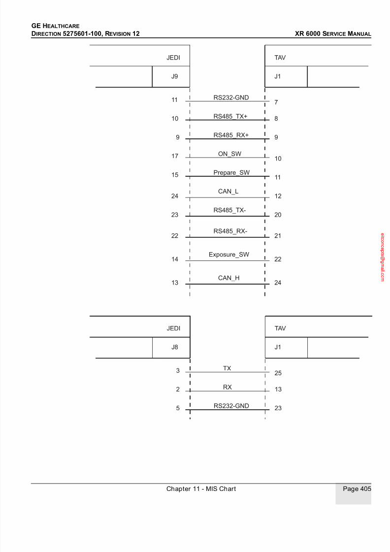
7/24/2019 GE XR6000 X-Ray - Service Manual
http://slidepdf.com/reader/full/ge-xr6000-x-ray-service-manual 405/421
GE HEALTHCARE
DIRECTION 5275601-100, REVISION 12 XR 6000 SERVICE MANUAL
Chapter 11 - MIS Chart Page 405
JEDI TAV
11
J9 J1
10 8
9 9
17
RS485_TX+
RS485_RX+
15 11Prepare_SW
24
23 20RS485_TX-
10ON_SW
RS232-GND7
CAN_L 12
22 21RS485_RX-
14 22Exposure_SW
13 24CAN_H
JEDI TAV
3
J8 J1
2 13
5 23
RX
RS232-GND
TX25
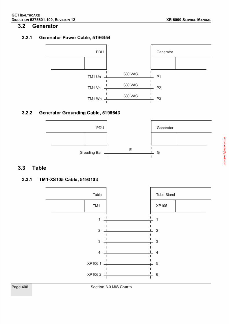
7/24/2019 GE XR6000 X-Ray - Service Manual
http://slidepdf.com/reader/full/ge-xr6000-x-ray-service-manual 406/421
GE HEALTHCARE
DIRECTION 5275601-100, REVISION 12 XR 6000 SERVICE MANUAL
Page 406 Section 3.0 MIS Charts
3.2 Generator
3.2.1 Generator Power Cable, 5196454
3.2.2 Generator Grounding Cable, 5196643
3.3 Table3.3.1 TM1-XS105 Cable, 5193103
PDU Generator
TM1 Un P1
TM1 Vn P2
TM1 Wn P3
380 VAC
380 VAC
380 VAC
PDU Generator
Grouding Bar GE
Tube StandTable
1 1
2 2
3 3
4 4
XP106 1 5
XP105TM1
XP106 2 6
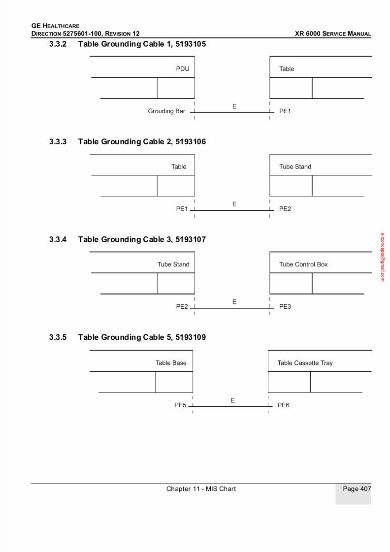
7/24/2019 GE XR6000 X-Ray - Service Manual
http://slidepdf.com/reader/full/ge-xr6000-x-ray-service-manual 407/421
GE HEALTHCARE
DIRECTION 5275601-100, REVISION 12 XR 6000 SERVICE MANUAL
Chapter 11 - MIS Chart Page 407
3.3.2 Table Grounding Cable 1, 5193105
3.3.3 Table Grounding Cable 2, 5193106
3.3.4 Table Grounding Cable 3, 5193107
3.3.5 Table Grounding Cable 5, 5193109
PDU Table
Grouding Bar PE1E
Table Tube Stand
PE1 PE2E
Tube Stand Tube Control Box
PE2 PE3E
Table Base Table Cassette Tray
PE5 PE6E

7/24/2019 GE XR6000 X-Ray - Service Manual
http://slidepdf.com/reader/full/ge-xr6000-x-ray-service-manual 408/421
GE HEALTHCARE
DIRECTION 5275601-100, REVISION 12 XR 6000 SERVICE MANUAL
Page 408 Section 3.0 MIS Charts
3.3.6 Table Power Cable, 5193607
3.3.6.1 Table MC7 Cable, 5197242
PDU TM2 Table TM1
5 3
6 4
7 8
24 V
0 V
foot-1
8 224 V
9 10 V
Tube StandControl Box
1 1
2 2
MC7 CableXP102
24V
0V

7/24/2019 GE XR6000 X-Ray - Service Manual
http://slidepdf.com/reader/full/ge-xr6000-x-ray-service-manual 409/421
GE HEALTHCARE
DIRECTION 5275601-100, REVISION 12 XR 6000 SERVICE MANUAL
Chapter 11 - MIS Chart Page 409
3.3.7 Table Cable No1, 5197244
Tube StandControl Box / Collimator
Control Box XS103 1 XP101 1
XP101 2Control Box XS103 2
Control Box XS103 3
XP105 1Control Box XS103 4
XP105 2Control Box XS103 5
XP105 3
Collimator Connector 1 XP105 4
Collimator Connector 2 XP105 5
Collimator Connector 3 XP105 6
Collimator Connector 4

7/24/2019 GE XR6000 X-Ray - Service Manual
http://slidepdf.com/reader/full/ge-xr6000-x-ray-service-manual 410/421
GE HEALTHCARE
DIRECTION 5275601-100, REVISION 12 XR 6000 SERVICE MANUAL
Page 410 Section 3.0 MIS Charts
This page is intentionally left blank.

7/24/2019 GE XR6000 X-Ray - Service Manual
http://slidepdf.com/reader/full/ge-xr6000-x-ray-service-manual 411/421
GE HEALTHCARE
DIRECTION 5275601-100, REVISION 12 XR 6000 SERVICE MANUAL
Appendix A - Elec tromagnetic Compatibi li ty (EMC) Page 411
Appendix A - Electromagnetic Compatibility
(EMC)
Section 1.0
Compliance Statement
This equipment complies with IEC 60601-1-2:2001+A1:2004 EMC standard for medical devices.
This equipment generates, uses, and can radiate radio frequency energy. The equipment may
cause radio frequency interference to other medical and non-medical devices and radio
communications.
To provide reasonable protection against such interference, this product complies the radiated
emission as per CISPR11 Group1 Class A standard limits.
However, there is no guarantee that interference will not occur in a particular installation.If this equipment is found to cause interference (which may be determined by turning the equipment
on and off), the user (or qualified service personnel) should attempt to correct the problem by one
or more of the following measure(s):
• Reorient or relocate the affected device(s)
• Increase the separation between the equipment and the affected device (see recommended
separation distances)
• Power the equipment from a source different from that of the affected device
• Consult the point of purchase or service representative for further suggestions
Use of accessories, transducers, cables and other parts other than those specified by the
manufacturer of this equipment may result in increased emissions or decreased immunity of the
equipment.The manufacturer is not responsible for any interference caused by using other than recommended
interconnect cables or by unauthorized changes or modifications to this equipment. Unauthorized
changes or modifications could void the users' authority to operate the equipment.
All interconnect cables to peripheral devices must be shielded and properly grounded, except when
technologically prohibited. Use of cables not properly shielded and grounded may result in the
equipment causing radio frequency interference.
The XR 6000 is predominantly intended for use in non-domestic environments, and not directly
connected to the Public Mains Network that supplies buildings used for domestic purposes.
The compatible accessories must be used within the recommended operating conditions outlined
in the operation manuals. In addition to calibration and warm-up, other devices must be reset before
and after use to ensure accurate dose measurements. Sustained exposure to electromagneticfields (exceeding the test conditions) may cause false measurements. Failure to follow the
recommended use may cause false measurements.
The magnetic field environment from a MRI device located nearby is a risk of interference.
All of the above are required to achieve the Electromagnetic Compatibility for a typical installation
of the XR 6000. Further detailed data & requirements are described in the Use Recommendations
and Installation Recommendations sections.

7/24/2019 GE XR6000 X-Ray - Service Manual
http://slidepdf.com/reader/full/ge-xr6000-x-ray-service-manual 412/421
GE HEALTHCARE
DIRECTION 5275601-100, REVISION 12 XR 6000 SERVICE MANUAL
Page 412 Section 2.0 Compatibility Tables
Section 2.0 Compatibility Tables
This equipment complies with IEC 60601-1-2:2001+A1:2004 EMC standard for medical devices.
The XR 6000 is suitable to be used in an electromagnetic environment, as per the limits &
recommendations described in the tables hereafter:
• Emission Compliance level & limits (Table 1).
• Immunity Compliance level & recommendations to maintain equipment clinical utility (see
Table 2 and Table 3).
Note: This system complies with above mentioned EMC standard when used with supplied cables.
If different cable lengths are required, contact a qualified service representative for advice.
2.1 Electromagnetic Emission
Guidance and manufacturer’s declaration – Electromagnetic Emissions
The XR 6000 is intended for use in the electromagnetic environment specified below. Thecustomer or the user of the XR 6000 should assure that it is used in such an environment.
Emissions Test Compliance Electromagnetic Environment Guidance
RF emission,
CISPR 11
Group 1 The XR 6000 uses RF energy only for its internal
function. Therefore, its RF emissions are very low and
are not likely to cause any interference in nearby
electronic equipment.
RF emissions,
CISPR 11
Class A The XR 6000 is suitable for use in non-domestic
environments, and not directly connected to the Public
Mains Network. The XR 6000 is predominantly intended
for use (e.g. in hospitals) with an appropriate power
supply (see operation manual) and the recommendedshielding for portable use.
Harmonic emissions,
IEC 61000-3-2
Not applicable
Voltage fluctuations/
flicker emissions,
IEC 61000-3-3
Not applicable
Table 1 XR 6000 Electromagnetic Emission

7/24/2019 GE XR6000 X-Ray - Service Manual
http://slidepdf.com/reader/full/ge-xr6000-x-ray-service-manual 413/421
GE HEALTHCARE
DIRECTION 5275601-100, REVISION 12 XR 6000 SERVICE MANUAL
Appendix A - Elec tromagnetic Compatibi li ty (EMC) Page 413
2.2 Electromagnetic Immunity
Guidance and Manufacturer’s declaration – electromagnetic immunity.
The XR 6000 is intended for use in the electromagnetic environment specified below. The customer or the user
of the XR 6000 should assure that it is used in such an environment.
Immunity Test IEC 60601-1-2 Test Level Compliance Level Electromagnetic Environment
Guidance
Electrostatic
discharge (ESD),
IEC 61000-4-2
6 kV contact.
8 kV air.
6 kV contact.
8 kV air.
Floors should be wood,
concrete, or ceramic tile. If floors
are covered with synthetic
material, the relative humidity
should be at least 30%.
Electrical fast
transient/burst,
EC 61000-4-4
2 kV for power supply
lines.
1 kV for input/output
lines.
2 kV for power supply
lines.
1 kV for input/output
lines.
Mains power quality should be
that of a typical commercial or
hospital environment
Surge,
IEC 61000-4-5
1 kV differential mode.
2 kV common mode.
1 kV differential mode.
2 kV common mode.
Mains power quality should be
that of a typical commercial or
hospital environment.
Voltage dips, short
interruptions and
voltage variations on
power supply input
lines, IEC 61000-4-
11
< 5% UT, (> 95% dip in UT)
for 0.5 cycle.
40% UT (60% dip in UT)
for 5 cycles.
70% UT (30% dip in UT) for
25 cycles.
< 5% UT, (> 95% dip in UT)
for 5 sec.
0% UT for 5 sec. Mains power quality should be
that of a typical commercial or
hospital environment. If the user
of the XR 6000 requires
continued operation during
power mains interruptions, it is
recommended that the XR 6000
be powered from an
uninterruptible power supply or abattery.
Power frequency (50/
60 Hz) magnetic field,
IEC 61000-4-8
3 A/m 3 A/m Power frequency magnetic fields
should be at levels characteristic
of a typical location in a typical
commercial or hospital
environment.
Note: These are guidelines. Actual conditions may vary.
Table 2 XR 6000 Electromagnetic Immunity

7/24/2019 GE XR6000 X-Ray - Service Manual
http://slidepdf.com/reader/full/ge-xr6000-x-ray-service-manual 414/421
GE HEALTHCARE
DIRECTION 5275601-100, REVISION 12 XR 6000 SERVICE MANUAL
Page 414 Section 2.0 Compatibility Tables
Guidance and Manufacturer’s declaration - electromagnetic immunity. The XR 6000 is suitable for use in the specified
electromagnetic environment. The customer or the user of the XR 6000 should assure that it is used in an
electromagnetic environment as described below.
Immunity Test IEC 60601-1-2
Test Level
Compliance
Level
Electromagnetic Environment Guidance
Conducted RF,
IEC 61000-4-6
3 Vrms, 150 kHz to
80 MHz
V1 = 3Vrms Portable and mobile RF communications equipment
should be used no closer to any part of the XR 6000,
including cables, than the recommended separation
distance calculated from the equation appropriate for the
frequency of the transmitter.
Recommended Separation Distance
80 MHz to 800 MHz
800 MHz to 2.5 GHz
where, P is the maximum output power rating of the
transmitter in watts (W) according to the transmitter
manufacturer and d is the recommended separation
distance in metres (m).
Field strengths from fixed RF transmitters, as
determined by an electromagnetic site surveya, should
be less than the compliance level in each frequency
rangeb.
Interference may occur in the vicinity of equipment
marked with the following symbol:
Radiated RF
IEC 61000-4-3
3 V/m, 80 MHz to
2.5 GHz
E1 = 3V/m
a Field strengths from fixed transmitters, such as base stations for radio (cellular/cordless) telephones and land
mobile radios, amateur radio, AM and FM radio broadcast, and TV broadcast cannot be predicted theoretically with
accuracy. To assess the electromagnetic environment due to fixed RF transmitters, an electromagnetic site survey
should be considered. If the measured field strength in the location in which the XR 6000 is used exceeds the applicable
RF compliance level above, the XR 6000 should be observed to verify normal operation. If abnormal performance is
observed, additional measures may be necessary, such as re-orienting or relocating the XR 6000.
b Over the frequency range 150 kHz to 80 MHz, field strengths should be less than [V1] V/m.
These guidelines may not apply in all situations. Electromagnetic propagation is affected by absorption and reflection
from structures, objects, and people.
Table 3 XR 6000 Electromagnetic Immunity (Continued)
d = 1.2
d = 1.2
d = 2.3
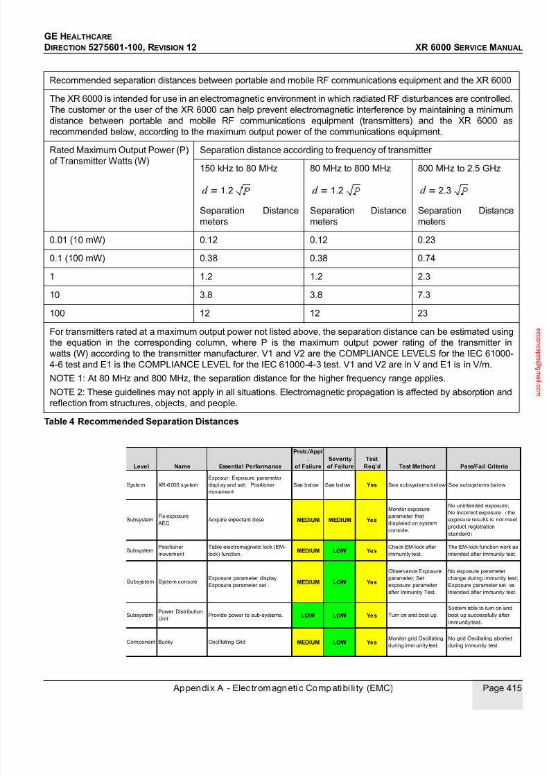
7/24/2019 GE XR6000 X-Ray - Service Manual
http://slidepdf.com/reader/full/ge-xr6000-x-ray-service-manual 415/421
GE HEALTHCARE
DIRECTION 5275601-100, REVISION 12 XR 6000 SERVICE MANUAL
Appendix A - Elec tromagnetic Compatibi li ty (EMC) Page 415
Recommended separation distances between portable and mobile RF communications equipment and the XR 6000
The XR 6000 is intended for use in an electromagnetic environment in which radiated RF disturbances are controlled.
The customer or the user of the XR 6000 can help prevent electromagnetic interference by maintaining a minimum
distance between portable and mobile RF communications equipment (transmitters) and the XR 6000 as
recommended below, according to the maximum output power of the communications equipment.Rated Maximum Output Power (P)
of Transmitter Watts (W)
Separation distance according to frequency of transmitter
150 kHz to 80 MHz
Separation Distance
meters
80 MHz to 800 MHz
Separation Distance
meters
800 MHz to 2.5 GHz
Separation Distance
meters
0.01 (10 mW) 0.12 0.12 0.23
0.1 (100 mW) 0.38 0.38 0.74
1 1.2 1.2 2.3
10 3.8 3.8 7.3
100 12 12 23
For transmitters rated at a maximum output power not listed above, the separation distance can be estimated using
the equation in the corresponding column, where P is the maximum output power rating of the transmitter in
watts (W) according to the transmitter manufacturer. V1 and V2 are the COMPLIANCE LEVELS for the IEC 61000-
4-6 test and E1 is the COMPLIANCE LEVEL for the IEC 61000-4-3 test. V1 and V2 are in V and E1 is in V/m.
NOTE 1: At 80 MHz and 800 MHz, the separation distance for the higher frequency range applies.
NOTE 2: These guidelines may not apply in all situations. Electromagnetic propagation is affected by absorption and
reflection from structures, objects, and people.
Table 4 Recommended Separation Distances
d = 1.2 d = 1.2 d = 2.3
Level Name Essential Performance
Prob./Appl.
of FailureSeverity
of FailureTest
Req’d Test Methord Pass/Fail Criteria
Sys tem XR-6000 sys tem
Exposur; Exposure parameter
display and set; Positioner
movement.
See below See below Yes See subsystems below See subsystems below
SubsystemFix exposure
AEC Acquire expectant dose MEDIUM MEDIUM Yes
Monitor exposure
parameter that
displaied on system
console.
No unintended exposure;
No Incorrect exposure (the
exposure results is not meet
product registration
standard)
SubsystemPositioner
movement
Table electromagnetic lock (EM-
lock) function.MEDIUM LOW Yes
Check EM-lock after
immunity test.
The EM-lock function work as
intended after immunity test.
Subsystem System consoleExposure parameter display
Exposure parameter set .MEDIUM LOW Yes
Observance Exposure
parameter; Set
exposure parameter
after Immunity Test.
No exposure parameter
change during immunity test;
Exposure parameter set as
intended after immunity test.
SubsystemPower Distribution
UnitProvide power to sub-systems. LOW LOW Yes Turn on and boot up.
System able to turn on and
boot up successfully after
immunity test.
Component Bucky Oscillating Grid MEDIUM LOW YesMonitor grid Oscillating
during imm unity test.
No grid Oscillating aborted
during immunity test.
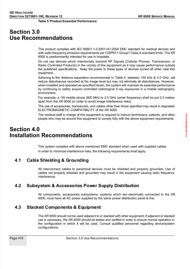
7/24/2019 GE XR6000 X-Ray - Service Manual
http://slidepdf.com/reader/full/ge-xr6000-x-ray-service-manual 416/421
GE HEALTHCARE
DIRECTION 5275601-100, REVISION 12 XR 6000 SERVICE MANUAL
Page 416 Section 3.0 Use Recommendations
Table 5 Product Essential Performance
Section 3.0 Use Recommendations
This product complies with IEC 60601-1-2:2001+A1:2004 EMC standard for medical devices and
with radio frequency emission requirements per CISPR11 Group1 Class A standard limits. The XR
6000 is predominantly intended for use in hospitals.
Do not use devices which intentionally transmit RF Signals (Cellular Phones, Transceivers, or
Radio Controlled Products) in the vicinity of this equipment as it may cause performance outside
the published specifications. Keep the power to these types of devices turned off when near this
equipment.
Adhering to the distance separation recommended in Table 4, between 150 kHz & 2.5 GHz, will
reduce disturbances recorded at the image level but may not eliminate all disturbances. However,
when installed and operated as specified herein, the system will maintain its essential performance
by continuing to safely acquire controlled radiological X-ray exposures in a mobile radiography
environment.For example, a 1W mobile phone (800 MHz to 2.5 GHz carrier frequency) shall be put 2.3 meters
apart from the XR 6000 (in order to avoid image interference risks).
The use of accessories, transducers, and cables other than those specified may result in degraded
ELECTROMAGNETIC COMPATIBILITY of the XR 6000.
The medical staff in charge of this equipment is required to instruct technicians, patients, and other
people who may be around this equipment to comply fully with the above equipment requirements.
Section 4.0
Installation Recommendations
This system complies with above mentioned EMC standard when used with supplied cables.
In order to minimize interference risks, the following requirements shall apply.
4.1 Cable Shielding & Grounding
All interconnect cables to peripheral devices must be shielded and properly grounded. Use of
cables not properly shielded and grounded may result in the equipment causing radio frequency
interference.
4.2 Subsystem & Accessories Power Supply Distribution
All components, accessories subsystems, systems which are electrically connected to the XR
6000, must have all AC power supplied by the same power distribution panel & line.
4.3 Stacked Components & Equipment
The XR 6000 should not be used adjacent to or stacked with other equipment; if adjacent or stacked
use is necessary, the XR 6000 should be tested and verified in order to ensure normal operation in
the configuration in which it will be used. Consult qualified personnel regarding device/system
configurations.
7/24/2019 GE XR6000 X-Ray - Service Manual
http://slidepdf.com/reader/full/ge-xr6000-x-ray-service-manual 417/421
GE HEALTHCARE
DIRECTION 5275601-100, REVISION 12 XR 6000 SERVICE MANUAL
Appendix A - Elec tromagnetic Compatibi li ty (EMC) Page 417
4.4 Low Frequency Magnetic Field
Not applicable.
4.5 Electrostatic Discharge Environment & Recommendations
In order to reduce electrostatic discharge interference, install a charge dissipative floor material toavoid electrostatic charge buildup.
The relative humidity shall be at least 30 percent.
The dissipative material shall be connected to the system ground reference, if applicable.

7/24/2019 GE XR6000 X-Ray - Service Manual
http://slidepdf.com/reader/full/ge-xr6000-x-ray-service-manual 418/421
GE HEALTHCARE
DIRECTION 5275601-100, REVISION 12 XR 6000 SERVICE MANUAL
Page 418 Section 4.0 Installation Recommendations

7/24/2019 GE XR6000 X-Ray - Service Manual
http://slidepdf.com/reader/full/ge-xr6000-x-ray-service-manual 419/421
GE HEALTHCARE
DIRECTION 5275601-100, REVISION 12 XR 6000 SERVICE MANUAL
Appendix B - Revision His to ry Page 419
Appendix B - Revision History
Revision Date Reason for change
1 June 20, 2007 First Release
2 Nov. 08, 2007 Add cabinet tray pull/push location, silicone compound to HVcables, PDU troubleshootings, part replacement, Jedi schematics,and PM formUpdate table unpacking process, accuracy of x-ray field and lightfield alignment, table top part number
3 Feb. 15, 2008 Remove "LING LONG" Add door light and gate command pin direction Add Collimator PM
4 April 25, 2008 Add technique factors measurement criteria. Add CR AEC calibration process. Add tube stand bearing replacement instruction Add note to grid installation instruction. Add instruction to table leveling adjustment. Add system configuration instruction.
5 Aug 28,2008 Add installation instruction for oscillate grid for the systemconfigured with advanced tube stand and advanced wall stand. Add HHS test instruction.
6 Mar 09, 2011 Update tube voltage accuracy in chapter 4.Update FRU list
7 Aug 18, 2011 Revise EMC standard version
8 Jun 15,2012 Add Bucky Handle Assembly to FRU list.
9 Jun 29, 2012 Add requirement to meet the 3rd edition IEC60601 standards.
10 Jun 25, 2014 Remove CE Mark.
11 Aug 25, 2014 Add CE Mark. update Figure 2-55
12 Oct 30, 2014 Add LOCTITE 242(or 243) requirements during the tubeinstallation; Add FRU parts Item 63, item 64

7/24/2019 GE XR6000 X-Ray - Service Manual
http://slidepdf.com/reader/full/ge-xr6000-x-ray-service-manual 420/421
GE HEALTHCARE
DIRECTION 5275601-100, REVISION 12 XR 6000 SERVICE MANUAL
Page 420 Appendix B - Revision History

7/24/2019 GE XR6000 X-Ray - Service Manual
http://slidepdf.com/reader/full/ge-xr6000-x-ray-service-manual 421/421