Embed Size (px)
Citation preview

International Journal of Research in Engineering and Science (IJRES)
ISSN (Online): 2320-9364, ISSN (Print): 2320-9356 www.ijres.org Volume 9 Issue 8 ǁ 2021 ǁ PP. 54-67
www.ijres.org 54 | Page
Analysis and design of elevated water tank for different seismic
zones
Gayathri Devi R (Student at dept of civil engineering, NCET Bangalore)
Chaitra D M (Asst. Professor at dept of civil engineering, NCET Bangalore)
Abstract Water tanks are widely used for storing potable water. Large capacity elevated circular tanks are used to store
a variety of liquids, e.g. water for drinking and fire fighting, petroleum, chemicals, and liquefied natural gas. A
water tank is used to store to tide over the daily requirements. Due to lack of water around the world,
importance is given more on the water storage project. So water storage is very important as it plays a vital role
in everyday life. The recent edition for the design concerning towards liquid retaining structure have been
revised. Elevated water tanks are one of the most lifeline structures in earthquake prone regions. They are
critical elements in municipal water supply, firefighting systems and in many industrial facilities for storage of
water. Hence elevated water tanks must remain functional even after the earthquake.
The main aim of this study is to analyze and design the circular elevated water tank in different seismic zones
due to earthquake using ETABS software. Any Civil Engineering structures are conceived keeping in mind its
intended use, the materials available, cost and aseptic considerations.. Key Words: Elevated circular water tank, ETABS.
---------------------------------------------------------------------------------------------------------------------------------------
Date of Submission: 01-08-2021 Date of acceptance: 15-08-2021
---------------------------------------------------------------------------------------------------------------------------------------
I. INTRODUCTION
Water plays very important role in everyday life, so water storage is very important. In general,
depending upon the location tanks are classified as tank resting on ground, underground water tank, and
overhead or elevated water tank. Depending upon their shape, water tanks are further classified as rectangular
tanks, circular tanks and intze tanks. An elevated water tank is a large water storage container constructed for
the purpose of holding water supply at certain height to provide sufficient pressure in the water distribution
system. Elevated water tanks consists of huge water mass at the top of the slender staging which are most critical consideration for the failure of the tank during earthquakes.
Elevated water tanks are critical and strategic structures and the damage of these structures during
earthquakes may endanger drinking water supply, cause to fail in preventing large files and substantial
economic loss. The elevated water tanks are frequently used in seismic active regions. Due to the lack of
knowledge of supporting system some of the water tanks were collapsed or heavily damaged. So there is need to
focus on seismic safety of lifeline structures with respect to alternate supporting system which are safe during
earthquake and also to withstand more design forces.
Circular water tank
The circular over head tanks are used to store water up to 7, 50,000 liters. The diameter varies from 5
to 15m m. The water tank is the container to store water for purposes of distribution, irrigation, fire extinguish, or future use. Water can be of any shape and size as per requirement. The design of circular water tank is
necessary for the economical and safe use of tanks.
[Document title]
Static earthquake method: Static analysis is a design approach where equivalent static story forces, due to wind or earthquakes,
are applied to the structure. The computation of story forces is prescriptive, and formulations for calculating
these forces are provided within the applicable building code. Linear static analysis is typically restricted to use
in regular structures, where dynamic behavior is dominated by the fundamental mode of vibration, without
significant higher modes and torsion effects and in regions of low seismicity.
Since tall buildings often exhibit significant higher mode effects and the effects of torsion are
important, linear dynamic analysis, instead of linear static analysis, is typically conducted for the seismic design of tall buildings, even in regions of low seismicity.

Analysis and design of elevated water tank for different seismic zones
www.ijres.org 55 | Page
Seismic zone:
The varying geology at different locations in the country implies that the likelihood of damaging
earthquakes taking place at different locations is different. Thus, a seismic zone map is required to identify these regions. Based on the levels of intensities sustained during damaging past earthquakes, the 1970 version of the
zone map subdivided India into four zones – II, III, IV and V (Figure 3). The maximum Modified Mercalli
(MM) intensity of seismic shaking expected in these zones were V or less, VI, VII, VIII, and IX and higher,
respectively. Parts of Himalayan boundary in the north and northeast, and the Kachchh area in the west were
classified as zone V.
II. OBJECTIVES:
To study about the analysis and design of water tank.
Comparing the structural responses of tanks for different seismic zones.
To know about the design philosophy for the safe an economical design of water tank.
To optimize the shape, size and number of columns to resist the forces in critical zone.
III. METHODOLOGY:
In this present study, the behaviors of the structure due to different seismic zones were studied. Plans of
water tanks are analyzed using ETABS 18.0.0 software. ETABS is one of the most useful and friendly software
which is developed by Computers and Structural Engineers of U.S.A. In this project static loads are considered
for the study. i.e. (Earthquake loads in x and y direction and Wind loads). Analysis is carryout through Static
Earthquake Method and subjected to Diaphragm, mass sources, and load combinations. Extracting the results for
different seismic zones of water tank from the ETABS software and comparing it with each other. Extracted
analysis result are mainly focused on different parameters like Average drift, Storey displacement, Overturning
moments an Shear of different seismic zones.
The Graphical User Interface
The graphical user interface is shown in Figure. Several important features of the interface are shown. Those
features include the main window, main title bar, display title bar, menu bar, toolbars, display windows, status
bar, mouse pointer position coordinates and the current units.
LOAD SPECIFICATIONS:
The structures are under different loads such as Dead load (DL), Live load (LL), Earthquake load (EQ) and
Wind load (WL).
1. Water load: density x height of the wall = 10 x 2.5 =25kN/m2.
2. Wind load: Wind loads are considered as per, IS 875-part 3.
a. Wind speed: 33m/s
b. Terrain category: 2.
3. Seismic load: seismic loads are considered as per, IS 1893 (part-I) 2002.
a. Seismic zone: 2, 3, 4, 5
b. Zone factor Z: 0.1, 0.16, 0.24, 0.36.
c. Soil type: II (medium soil).
d. Importance factor: 1.5(Refer table 6).
e. Response reduction factor: 5 (Refer table 7) (OMRF-Ordinary RC Moment Resisting frame).
f. Structure type: RC frame Structure
WATER TANK SPECIFICATIONS:
Geometry and Material properties of the structure are given below.
1. Diameter of water tank calculation:
Calculation for 2lac litres
A=V/h
=200/2.5=80
A=3.14*r2
80=3.14*r2
r=5.04
D=10.09m 2. Number of stories: story4+tank grid.
3. Height: 15m.

Analysis and design of elevated water tank for different seismic zones
www.ijres.org 56 | Page
4. Grade of steel: Fe 500.
5. Grade of concrete: For Columns - 25 Mpa.
For Beams – 25 Mpa. 6. Support conditions: Fixed.
7. Size of columns : 400 x 400mm
8. Size of beams: 450 x 230mm.
9. Thickness of wall: 250mm.
10. Thickness of slab: 250mm.
Before section properties, grid data is given i.e. column grid and tank grid.
Figure 1: 3D view of water tank after grid system
STATIC SEISMIC LOADING:
The automatic data entry of equivalent static seismic loads according to various standards is applicable for
common buildings where each story can be defined and can reasonably act as a rigid diaphragm. The parameters
are to be applied to the seismic load calculation.
Seismic Load Direction Factor
Enter the directions and magnitudes of the seismic loads to be applied.
Scale Factor in Global X: Scale factor in GCS X-direction.
Scale Factor in Global Y: Scale factor in GCS Y-direction. As per code seismic zone factor for zone 2: 0.1,zone 3: 0.16,zone 4: 0.24 and zone 5: 0.36.
Importance factor: 1.5.
Assigning proprerties:
Figure 2: Plan view and 3d view after assigning model
MODELLING AND ANALYSIS IN ETABS:
Analysis:
After all the loads are assigned, now click analyze=>run analysis. After the complete structure is
analyzed, the deformed shape of the structure is shown in 3D view. This is due to the loads that are acting on all
the sections i.e., beam, columns, walls and slabs. The concrete design command is given to complete beam and
column design. The results of design can be viewed graphically or in the form of table.
Design reactions exporting.

Analysis and design of elevated water tank for different seismic zones
www.ijres.org 57 | Page
Zone 2:
Figure 3: Plan view and 3d model of zone 2 after analysis
Zone 3:
Figure 4: Plan view and 3d model of zone 3 after analysis
[Document title]
Zone 4:
Figure 5: Plan view and 3d model of zone 4 after analysis
Zone 5:
Figure 6: Plan view and 3d model of zone 5 after analysis
IV. RESULTS AND DISCUSSION: After modeling and analysis by using ETABS, the graphical results of water tank are shown below in
terms of story displacement, story drift, story shear and overturning moments. The results of each zone and
comparison are discussed below using MS Excel.

Analysis and design of elevated water tank for different seismic zones
www.ijres.org 58 | Page
GRAPHICAL REPRESENTATION:
Story displacement:
Total displacement of any storey with respect to ground and there is maximum permissible limit prescribed in IS codes.
Permissible story displacement is H/300.
Max story displacement for combo: 0.9water load+0.9dead load+1.5eqx (dcon 17)
Figure 7: comparison of story displacement dcon17
[Document title]
From the below table, it clearly shows that max displacement is 28.967mm, for zone 5 at 15m height.
Max displacement for zone 2 is 8.064mm, zone 3 is 12.888mm, zone 4 is 19.319mm and zone 5 is
28.967mm.
By considering different zones, zone 5 getting maximum story displacements which contains maximum
zone factor 0.36 and zone 2 getting least story displacement which contains zone factor 0.1.
As per IS: 1893 the max total deflection is total height/300 i.e.; 15000/300=50mm, the deflection is in
control.
Max story displacement for combo: 0.9water load+0.9dead load-1.5eqx (dcon 18)
Figure 8: comparison of story displacement dcon18
From the below table, it clearly shows that max displacement is 28.917mm, for zone 5 at 15m height.
Max displacement for zone 2 is 8.015mm, zone 3 is 12.838mm, zone 4 is 19.27mm and zone 5 is
28.917mm.
By considering different zones, zone 5 getting maximum story displacements which contains maximum
zone factor 0.36 and zone 2 getting least story displacement which contains zone factor 0.1.
As per IS: 1893 the max total deflection is total height/300 i.e.; 15000/300=50mm, the deflection is in
control.
0, 0 0, 0 0
5
10
15
20
0 10 20 30 40
El
eva
tio
n
displacement mm
Story displacement dcon 17
story displacement zone 2
story displacement zone 3
story displacement zone 4
story displacement zone 5
0
5
10
15
20
0 10 20 30 40
Ele
vati
on
Story displacement
Story displacement dcon 18
story displacement zone 2
story displacement zone 3
story displacement zone 4
story displacement zone 5

Analysis and design of elevated water tank for different seismic zones
www.ijres.org 59 | Page
Max story displacement for combo: 0.9water load+0.9dead load+1.5eqy (dcon 19)
Figure 9: comparison of story displacement dcon19
[Document title]
• From the below table, it clearly shows that max displacement is 28.946mm, for zone 5 at 15m height.
• Max displacement for zone 2 is 8.252mm, zone 3 is 13.028mm, zone 4 is 19.395mm and zone 5 is 28.946mm.
• By considering different zones , zone 5 getting maximum story displacement which contains maximum zone factor 0.36 and zone 2 getting least story displacement which contains zone factor 0.1
• As per IS: 1893 the max total deflection is total height/300 i.e.; 15000/300=50mm, the deflection is in control.
Max story displacement for combo: 0.9water load+0.9dead load-1.5eqy (dcon 20)
Figure 10: comparison of story displacement dcon20
• From the below table, it clearly shows that max displacement is 28.359mm, for zone 5 at 15m height.
• Max displacement for zone 2 is 7.666mm, zone 3 is 12.441mm, zone 4 is 18.808mm and zone 5 is 28.359mm.
• By considering different zones , zone 5 getting maximum story displacement which contains maximum zone factor 0.36 and zone 2 getting least story displacement which contains zone factor 0.1
• As per IS: 1893 the max total deflection is total height/300 i.e.; 15000/300=50mm, the deflection is in control.
Story drift: Story drift is the difference of displacements between two consecutive stories divided by the height of that
story. Drift is a very complex topic in structural engineering. It is the lateral displacement of one level relative to
the level above or below. Story drift ratio is the story drift divided by the story height.
0
5
10
15
20
0 10 20 30 40
Elev
atio
n
Story displacement
Story displacement dcon 19
story displacement zone 2
story displacement zone 3
story displacement zone 4
story displacement zone 5
0
5
10
15
20
0 10 20 30
Elev
atio
n
Story displacement
Story displacement dcon 20
story displacement zone 2
story displacement zone 3
story displacement zone 4

Analysis and design of elevated water tank for different seismic zones
www.ijres.org 60 | Page
Max story drifts for combo: 0.9water load+0.9dead load+1.5eqx (dcon 17)
Figure 11: comparison of story drift dcon17
• From the below table, it clearly shows that max drift is 0.00278, for zone 5 at 9m height.
• Max drift for zone 2 is 0.00079, zone 3 is 0.00125, zone 4 is 0.001862 and zone 5 is 0.00278.
• By considering different zones, zone 5 getting maximum story drifts which contains maximum zone factor 0.36 and zone 2 getting least story drift which contains zone factor 0.1.
• As per IS: 1893 the max drift is 0.01, the drift is in control.
Max story drifts for combo: 0.9water load+0.9dead load-1.5eqx (dcon 18)
Figure 12: comparison of story drift dcon18
• From the below table, it clearly shows that max drift is 0.002779, for zone 5 at 9m height.
• Max drift for zone 2 is 0.000789, zone 3 is 0.001248, zone 4 is 0.001862 and zone 5 is 0.00278.
• By considering different zones, zone 5 getting maximum story drifts which contains maximum zone factor 0.36 and zone 2 getting least story drift which contains zone factor 0.1.
• As per IS: 1893 the max drift is 0.01, the drift is in control.
0
5
10
15
20
0 0.001 0.002 0.003
Ele
vati
on
Story drifts
Story drifts dcon 17
story drifts zone 2
story drifts zone 3
story drifts zone 4
story drifts zone 5
0
5
10
15
20
0 0.001 0.002 0.003
Elev
atio
n
Story drifts
Story drifts dcon 18
story drifts zone 2
story drifts zone 3
story drifts zone 4
story drifts zone 5

Analysis and design of elevated water tank for different seismic zones
www.ijres.org 61 | Page
Max story drifts for combo: 0.9water load+0.9dead load+1.5eqy (dcon 19)
Figure 13: comparison of story drift dcon19
• From the below table, it clearly shows that max drift is 0.00279, for zone 5 at 9m height.
• Max drift for zone 2 is 0.0008, zone 3 is 0.001259, zone 4 is 0.001872 and zone 5 is 0.00279.
• By considering different zones, zone 5 getting maximum story drifts which contains maximum zone factor 0.36 and zone 2 getting least story drift which contains zone factor 0.1.
• As per IS: 1893 the max drift is 0.01, the drift is in control.
Max story drifts for combo: 0.9water load+0.9dead load-1.5eqy (dcon 20)
Figure 14: comparison of story drift dcon20
• From the below table, it clearly shows that max drift is 0.00277, for zone 5 at 9m height.
• Max drift for zone 2 is 0.00078, zone 3 is 0.001239, zone 4 is 0.001852 and zone 5 is 0.00277.
• By considering different zones, zone 5 getting maximum story drifts which contains maximum zone factor 0.36 and zone 2 getting least story drift which contains zone factor 0.1.
• As per IS: 1893 the max drift is 0.01, the drift is in control
Story shear:
In story shear, you can visualize the possible governing lateral load on a certain floor at a given direction. And
this will aid to understanding or investigating why wind governs over seismic on certain direction or vice versa.
0
5
10
15
20
0 0.001 0.002 0.003
Ele
vati
on
Story drifts
Story drifts dcon 19
story drifts zone 2
story drifts zone 3
story drifts zone 4
story drifts zone 5
0
5
10
15
20
0 0.001 0.002 0.003
Ele
vati
on
Story drifts
Story drifts dcon 20
story drifts zone 2
story drifts zone 3
story drifts zone 4
story drifts zone 5

Analysis and design of elevated water tank for different seismic zones
www.ijres.org 62 | Page
Story shears for combo: 0.9water load+0.9dead load+1.5eqx (dcon 17)
Figure 15: comparison of story shear dcon17
• From the below table, it clearly shows that max story shear is -42.0719kN, for zone 2 at 15m height.
• Story shear for zone 2 is -42.0719kN, zone 3 is -67.315kN, zone 4 is -100.9725kN and zone 5 is -
151.4587kN.
• By considering different zones , zone 2 getting maximum story shears which contains zone factor 0.1
and zone 5 getting least story shear which contains zone factor 0.36.
•
Story shears for combo: 0.9water load+0.9dead load-1.5eqx (dcon 18)
Figure 16: comparison of story shear dcon18
• From the below table, it clearly shows that max story shear is 42.0719kN, for zone 2 at 15m height.
• Story shear for zone 2 is 42.0719kN, zone 3 is 67.315kN, zone 4 is 100.9725kN and zone 5 is 151.4587kN.
• By considering different zones , zone 2 getting maximum story shears which contains zone factor 0.1 and zone 5 getting least story shear which contains zone factor 0.36 .
0
5
10
15
20
-500 -400 -300 -200 -100 0
Ele
vati
on
Story shears
Story shears dcon 17
story shears zone 2
story shears zone 3
story shears zone 4
story shears zone 5
0
5
10
15
20
0 100 200 300 400 500
Elev
atio
n
Story shears
Story shears dcon 18
story shears zone 2
story shears zone 3
story shears zone 4
story shears zone 5

Analysis and design of elevated water tank for different seismic zones
www.ijres.org 63 | Page
Story shears for combo: 0.9water load+0.9dead load+1.5eqy (dcon 19)
Figure 17: comparison of story shear dcon19
• From the below table, it clearly shows that max story shear is -42.0878kN, for zone 2 at 15m height.
• Story shear for zone 2 is -42.0878kN, zone 3 is -67.3406kN, zone 4 is -101.0108kN and zone 5 is -151.516kN.
• By considering different zones , zone 2 getting maximum story shears which contains zone factor 0.1 and zone 5 getting least story shear which contains zone factor 0.36 .
•
Story shears for combo: 0.9water load+0.9dead load-1.5eqy (dcon 20)
Figure 18: comparison of story shear dcon20
From the below table, it clearly shows that max story shear is 389.919kN, for zone 5 at 3m height.
Story shear for zone 2 is 108.3108kN, zone 3 is 173.2973kN, zone 4 is 259.946kN and zone 5 is
389.919kN.
By considering different zones , zone 5 getting maximum story shears which contains zone factor 0.36 and zone 2 getting least story shear which contains zone factor 0.1 .
Overturning moments:
The "overturning moment" at any horizontal plane is the moment on the structure as a whole resulting from the
dynamic earthquake forces above the plane, giving due regard to signs of the modal forces.
0
5
10
15
20
-600 -400 -200 0
Elev
atio
n
Story shears
Story shears dcon 19
story shears zone 2
story shears zone 3
story shears zone 4
story shears zone 5
0
5
10
15
20
0 100 200 300 400 500
Elev
atio
n
Story shears
Story shears dcon 20
story shears zone 2
story shears zone 3
story shears zone 4
story shears zone 5
Analysis and design of elevated water tank for different seismic zones
www.ijres.org 64 | Page
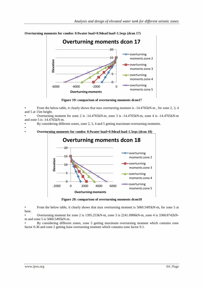
Overturning moments for combo: 0.9water load+0.9dead load+1.5eqx (dcon 17)
Figure 19: comparison of overturning moments dcon17
• From the below table, it clearly shows that max overturning moment is -14.4765kN-m , for zone 2, 3, 4 and 5 at 15m height.
• Overturning moment for zone 2 is -14.4765kN-m, zone 3 is -14.4765kN-m, zone 4 is -14.4765kN-m and zone 5 is -14.4765kN-m.
• By considering different zones, zone 2, 3, 4 and 5 getting maximum overturning moments.
•
• Overturning moments for combo: 0.9water load+0.9dead load-1.5eqx (dcon 18)
Figure 20: comparison of overturning moments dcon18
• From the below table, it clearly shows that max overturning moment is 5060.5495kN-m, for zone 5 at base.
• Overturning moment for zone 2 is 1395.253kN-m, zone 3 is 2241.0906kN-m, zone 4 is 3368.8742kN-m and zone 5 is 5060.5495kN-m.
• By considering different zones, zone 5 getting maximum overturning moment which contains zone factor 0.36 and zone 2 getting least overturning moment which contains zone factor 0.1.
0
5
10
15
20
-6000 -4000 -2000 0
Ele
vati
on
Overturning moments
Overturning moments dcon 17
overturning moments zone 2
overturning moments zone 3
overturning moments zone 4
overturning moments zone 5
0
5
10
15
20
-2000 0 2000 4000 6000
Elev
atio
n
Overturning moments
Overturning moments dcon 18
overturning moments zone 2
overturning moments zone 3
overturning moments zone 4
overturning moments zone 5
Analysis and design of elevated water tank for different seismic zones
www.ijres.org 65 | Page
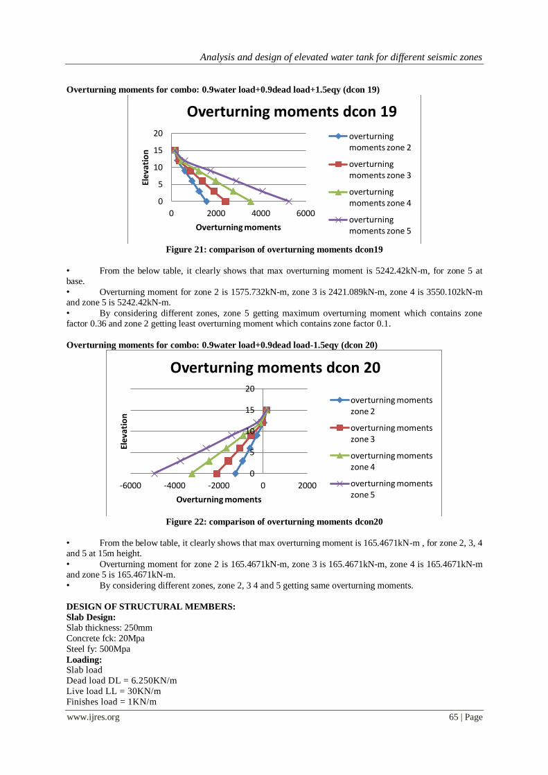
Overturning moments for combo: 0.9water load+0.9dead load+1.5eqy (dcon 19)
Figure 21: comparison of overturning moments dcon19
• From the below table, it clearly shows that max overturning moment is 5242.42kN-m, for zone 5 at base.
• Overturning moment for zone 2 is 1575.732kN-m, zone 3 is 2421.089kN-m, zone 4 is 3550.102kN-m and zone 5 is 5242.42kN-m.
• By considering different zones, zone 5 getting maximum overturning moment which contains zone factor 0.36 and zone 2 getting least overturning moment which contains zone factor 0.1.
Overturning moments for combo: 0.9water load+0.9dead load-1.5eqy (dcon 20)
Figure 22: comparison of overturning moments dcon20
• From the below table, it clearly shows that max overturning moment is 165.4671kN-m , for zone 2, 3, 4 and 5 at 15m height.
• Overturning moment for zone 2 is 165.4671kN-m, zone 3 is 165.4671kN-m, zone 4 is 165.4671kN-m and zone 5 is 165.4671kN-m.
• By considering different zones, zone 2, 3 4 and 5 getting same overturning moments.
DESIGN OF STRUCTURAL MEMBERS:
Slab Design:
Slab thickness: 250mm
Concrete fck: 20Mpa
Steel fy: 500Mpa
Loading: Slab load
Dead load DL = 6.250KN/m
Live load LL = 30KN/m
Finishes load = 1KN/m
0
5
10
15
20
0 2000 4000 6000
Ele
vati
on
Overturning moments
Overturning moments dcon 19
overturning moments zone 2
overturning moments zone 3
overturning moments zone 4
overturning moments zone 5
0
5
10
15
20
-6000 -4000 -2000 0 2000
Elev
atio
n
Overturning moments
Overturning moments dcon 20
overturning moments zone 2
overturning moments zone 3
overturning moments zone 4
overturning moments zone 5

Analysis and design of elevated water tank for different seismic zones
www.ijres.org 66 | Page
Total load = 37.250KN/m
Factored load = 56KN/m
Slab data: Slab type: Regular
Load: 56KN/m
Longer span (ly):4m
Shorter span (lx):2m
ly/lx ratio:2.00
Loading on edges one way two way
W longer 51 KN/m .=w*lx/2 .=(w*lx/2) + (1-
(1/3)*(lx/ly)2)
W shorter 37 KN/m .=w*lx/3
Moments
one way
two way
Mx 24 KN-m .=w*lx2/ 8 =αx * w*lx2
My 13 KN-m .=αy * w*lx2
Thickness Check OK =Mulim > Mux or Muy
Deflection 0 mm = 5*W*l4/(384EI)
Area of Steel Astx Asty
300 sqmm 300 sqmm
Spacing required in mm
8# 10# 12# 16#
x y x y x y x x
168 c/c 168 c/c 262 c/c 262 c/c 377 c/c 377 c/c 670 c/c 670 c/c
= ast of bar*1000/ast req
Final Ast
provided
x y
10@150 10@150
DESIGN OF ISOLATED FOOTING:
Footing size design:
Load Pu = 975KN
Design load P = 715KN
Moment in X direction Mux: 25KN-m
Moment in Y direction Muy: 1KN-m Column size Cx = 400mm
Cy = 400mm
SBC q = 180KN/sqm
Footing size required A: 3.97sqmm
Footing size provided: L= 2.20m
B= 2.20m
Area provided: 4.84mts
Zx= 1.77
Net upward pressure: 157KN/m2
FOOTING SIZE OK
Slab design: Lx= 0.900
Ly= 0.900
Bending moment in x dir Mx= 96KN-m
Bending moment in y dir My= 96KN-m
Concrete= 25Mpa
Steel= 500Mpa
Minimum depth required: 170

Analysis and design of elevated water tank for different seismic zones
www.ijres.org 67 | Page
Depth provided D= 600mm
Clear cover c = 50mm
Effective cover d' =56mm Effective depth d' =544mm
Area of Steel Spacing c/c in mm
12# 16# 20#
653 sqmm 173 c/c 308 c/c 481 c/c
653 sqmm 173 c/c 308 c/c 481 c/c
Minimum Ast required in x direction.
Minimum Ast required in y direction.
Ast across x direction 12mm dia @ 150mm c/s 754sqmm
Ast across y direction 12mm dia @ 150mm c/s 754sqmm
One way shear along x direction:
Vu1 = 185KN
Ζc = 0.155Mpa
Ζv = 0.263 Mpa
Vc1 = 315KN
One way shear check ok
One way shear along y direction:
Vu1 = 185KN
Ζc = 0.155Mpa
Ζv = 0.263 Mpa
Vc1 = 315KN
One way shear check ok
Two way shear:
Vu2 = 933KN
Ζc =0.454 Mpa
ks*Ζv =1.250 Mpa Vc1 =2568 KN
Two way shear check OK
Conclusion
• As per IS: 1893 the max total deflection is total height/300 i.e.; 15000/300=50mm, the deflection is in control.
• Zone 2 having lesser displacement and story shear compare to zone 3, 4 and 5.
• As per IS: 1893 the max drift is 0.01, the drift is in control.
• By considering different zones , zone 5 getting maximum story shears which contains zone factor 0.36
and zone 2 getting least story shear which contains zone factor 0.1 .
• By considering different zones, zone 5 getting maximum overturning moment which contains zone
factor 0.36 and zone 2 getting least overturning moment which contains zone factor 0.1.
• Reinforcement in columns and beams are more in zone 5 compared to other zones.
REFERENCE: [1]. Design of water tank by Nibedita Sahoo 10401010 Department of Civil engineering.
[2]. Urmila Ronad1,Raghu K.S2, Guruprasad T.N3.” SEISMIC ANALYSIS OF CIRCULAR ELEVATED TANK”, IRJET , Volume:
03 Issue: 09 | Sep-2016.
[3]. Tejaswini , Mamatha “Design and Analysis of Elevated Water Tank”, IRJET, Volume: 07 Issue: 08 | Aug 2020.
[4]. Nandagopan.M. 1 , Shinu Shajee, Dynamic Analysis of RCC Water Tanks with Varying Height of Water Level, IJIRSET, Vol. 6,
Issue 4, April 2017.
[5]. Mr. G. Praveen , Dr. P. Siva Prasad, Mr. Ch. Sri Varma , V. Sanjay Gokul Analysis and Design of Elevated Circular Over Head
Water Tank,IRJET.
[6]. Smt.Dhotre, Chandrakala(Ekbote S.S.) Lecturer in , Applied Mechanics Department, Government polytechnic Solapur. Final year
student, M.E. Structural Engg. Prof. Jawalkar G.C , Analysis on Overhead Circular water tank for various bearing capacity with
sloping ground, , IJSER, Volume 6, Issue 5, May-2015 .
[7]. Standard codes: IS 456:2000
[8]. Hemishkumar Patel1 , Prof. Jayeshkumar Pitroda2 , Dr. K. B. Parikh, Analysis of circular and rectangular overhead watertank,
Conference Paper · March 2014.