Embed Size (px)
Citation preview

■ Gate valves ■ Gate valve ■ 700 HJ/JJ (GA ■ PN 10-40) ■ PN 10-100 ■ DN 50-150
Technical alterations reserved6100.1.08.1140
Admissible operating pressure [bar] at design temperature [°C] 1)
Material PN -60 -10 20 120 150 200 250 300 350 400 425 450 475 500 510 520 530 540 550
1.0619 16 16,0 16,0 16,0 15,0 14,0 13,0 11,0 10,0 8,025 25,0 25,0 25,0 23,0 22,0 20,0 17,0 16,0 13,040 40,0 40,0 40,0 37,0 35,0 32,0 28,0 24,0 21,0
1.0460 10 2) 10,0 10,0 10,0 9,6 8,8 8,1 6,9 6,3 5,016 16,0 16,0 16,0 15,3 14,0 13,0 11,0 10,0 8,025 25,0 25,0 25,0 23,9 22,0 20,0 17,0 16,0 13,040 40,0 40,0 40,0 38,1 35,0 32,0 28,0 24,0 21,063 63,0 63,0 63,0 58,1 50,0 45,0 40,0 36,0 32,0
100 100,0 100,0 100,0 92,5 80,0 70,0 60,0 56,0 50,0
1.0566 3)4) 10 2) 10,0 10,0 10,0 10,0 10,0 9,0 8,0 7,016 2) 16,0 16,0 16,0 16,0 15,0 14,0 13,0 11,025 2) 25,0 25,0 25,0 25,0 24,0 22,0 20,0 17,040 2) 40,0 40,0 40,0 40,0 39,0 35,0 31,0 28,063 2) 63,0 63,0 63,0 63,0 61,0 55,0 49,0 44,0
100 2) 100,0 100,0 100,0 100,0 96,0 88,0 79,0 70,0
1.5415 10 2) 10,0 10,0 10,0 10,0 10,0 10,0 8,8 8,0 7,6 7,2 6,816 2) 16,0 16,0 16,0 16,0 16,0 16,0 14,1 12,8 12,2 11,5 10,9
25 25,0 25,0 25,0 25,0 25,0 25,0 22,0 20,0 19,0 18,0 17,040 40,0 40,0 40,0 40,0 40,0 40,0 35,0 31,0 30,0 29,0 28,063 63,0 63,0 63,0 63,0 63,0 63,0 56,0 50,0 47,0 46,0 45,0
100 100,0 100,0 100,0 100,0 100,0 100,0 87,0 78,0 74,0 72,0 70,0
1.7335 10 2) 10,0 10,0 10,0 10,0 10,0 10,0 10,0 9,6 9,2 8,8 8,4 8,0 7,2 6,0 4,8 3,616 2) 16,0 16,0 16,0 16,0 16,0 16,0 16,0 15,4 14,7 14,1 13,4 12,8 11,5 9,6 7,7 5,8
25 25,0 25,0 25,0 25,0 25,0 25,0 25,0 24,0 23,0 22,0 21,0 20,0 18,0 15,0 12,0 9,040 40,0 40,0 40,0 40,0 40,0 40,0 40,0 38,0 36,0 35,0 34,0 33,0 29,0 24,0 19,0 15,063 63,0 63,0 63,0 63,0 63,0 63,0 63,0 61,0 58,0 57,0 56,0 53,0 47,0 40,0 32,0 25,0
100 100,0 100,0 100,0 100,0 100,0 100,0 100,0 95,0 91,0 89,0 87,0 82,0 74,0 62,0 49,0 38,0
1.7383 10 2) 10,0 10,0 10,0 10,0 10,0 10,0 10,0 9,5 9,1 8,9 8,7 8,3 7,4 6,3 5,0 4,4 3,8 3,316 2) 16,0 16,0 16,0 16,0 16,0 16,0 16,0 15,2 14,6 14,2 13,9 13,2 11,8 10,0 7,9 7,0 6,0 5,225 2) 25,0 25,0 25,0 25,0 25,0 25,0 25,0 23,8 22,8 22,3 21,8 20,6 18,4 15,6 12,4 10,9 9,4 8,140 2) 40,0 40,0 40,0 40,0 40,0 40,0 40,0 38,0 36,4 35,6 34,8 33,0 29,5 25,0 19,8 17,4 15,1 13,063 2) 63,0 63,0 63,0 63,0 63,0 63,0 63,0 60,8 58,2 57,0 55,7 52,8 47,2 40,0 31,7 27,8 24,2 20,8
100 2) 100,0 100,0 100,0 100,0 100,0 100,0 100,0 95,0 91,0 89,0 87,0 82,5 73,8 62,5 49,5 43,5 37,8 32,5
1) Operating temperature = design temperature minus temperature surcharge acc. to DIN regulations. 2) Pressure rating not applicable in design code3) In case of stainless steel bolts (DIN material code A4-70) with > 8 x d bolt length the strength characteristics acc. to table 6 of DIN 267 part 11 have been considered.4) At temperature > 50 °C only applicable for short time service.
Pressure rate table acc. DIN 2401
■ Gate valves ■ Gate valve ■ 700 HJ/JJ (GA ■ PN 10-40) ■ PN 10-100 ■ DN 50-150
Technical alterations reserved 6100.1.08.11 41
Admissible operating pressure [bar] at design temperature [°C] 1)
Material PN -10 20 50 100 150 200 250 300 350 400 450 460 470 480 490 500 510 520 530 540 550 560 570 580 590 600
1.0619 16 16,0 16,0 16,0 14,8 14,0 13,3 12,1 11,0 10,2 9,5 5,225 25,0 25,0 25,0 23,2 22,0 20,8 19,0 17,2 16,0 14,8 8,240 40,0 40,0 40,0 37,1 35,2 33,3 30,4 27,6 25,7 23,8 13,1
1.0460 10 10,0 10,0 10,0 9,2 8,8 8,3 7,6 6,9 6,4 5,9 3,216 16,0 16,0 16,0 14,8 14,0 13,3 12,1 11,0 10,2 9,5 5,225 25,0 25,0 25,0 23,2 22,0 20,8 19,0 17,2 16,0 14,8 8,240 40,0 40,0 40,0 37,1 35,2 33,3 30,4 27,6 25,7 23,8 13,163 63,0 63,0 63,0 58,5 55,5 52,5 48,0 43,5 40,5 37,5 20,7
100 100,0 100,0 100,0 92,8 88,0 83,3 76,1 69,0 64,2 59,5 32,8
1.5415 10 10,0 10,0 10,0 10,0 10,0 10,0 9,7 8,5 8,0 7,4 6,9 6,4 5,9 5,4 4,9 4,4 3,5 2,8 2,216 16,0 16,0 16,0 16,0 16,0 16,0 15,6 13,7 12,9 11,9 11,0 10,2 9,4 8,6 7,8 7,0 5,6 4,4 3,525 25,0 25,0 25,0 25,0 25,0 25,0 24,4 21,4 20,2 18,6 17,2 16,0 14,7 13,5 12,3 11,0 8,8 7,0 5,540 40,0 40,0 40,0 40,0 40,0 40,0 39,0 34,2 32,3 29,9 27,6 25,6 23,6 21,6 19,7 17,7 14,0 11,2 8,963 63,0 63,0 63,0 63,0 63,0 63,0 61,5 54,0 51,0 47,1 43,5 40,3 37,2 34,1 31,0 27,9 22,2 17,7 14,1
100 100,0 100,0 100,0 100,0 100,0 100,0 97,6 85,7 80,9 74,7 69,0 64,0 59,1 54,2 49,2 44,2 35,2 28,0 22,3
1.7335 10 10,0 10,0 10,0 10,0 10,0 10,0 10,0 10,0 9,5 9,0 8,4 8,0 7,6 7,2 6,8 6,5 5,5 4,4 3,7 2,9 2,3 1,9 1,516 16,0 16,0 16,0 16,0 16,0 16,0 16,0 16,0 15,2 14,4 13,4 12,8 12,1 11,5 10,8 10,4 8,8 7,1 5,9 4,6 3,7 3,0 2,525 25,0 25,0 25,0 25,0 25,0 25,0 25,0 25,0 23,8 22,5 21,0 20,0 19,0 18,0 17,0 16,3 13,8 11,1 9,3 7,2 5,8 4,7 3,940 40,0 40,0 40,0 40,0 40,0 40,0 40,0 40,0 38,0 36,0 33,7 32,0 30,4 28,8 27,2 26,0 22,0 17,9 14,8 11,6 9,3 7,6 6,263 63,0 63,0 63,0 63,0 63,0 63,0 63,0 63,0 60,0 56,7 53,1 50,5 47,9 45,4 42,8 41,1 34,8 28,2 23,4 18,3 14,7 12,0 9,9
100 100,0 100,0 100,0 100,0 100,0 100,0 100,0 100,0 95,2 90,0 84,2 80,2 76,1 72,0 68,0 65,2 55,2 44,7 37,1 29,0 23,3 19,0 15,7
1.7383 10 10,0 10,0 10,0 10,0 10,0 10,0 10,0 10,0 9,7 9,2 8,8 8,3 7,8 7,3 6,9 6,4 5,6 4,9 4,2 3,7 3,2 2,7 2,4 2,0 1,8 1,616 16,0 16,0 16,0 16,0 16,0 16,0 16,0 16,0 15,6 14,8 14,0 13,3 12,5 11,8 11,0 10,2 8,9 7,8 6,8 5,9 5,1 4,4 3,8 3,3 2,8 2,525 25,0 25,0 25,0 25,0 25,0 25,0 25,0 25,0 24,4 23,2 22,0 20,8 19,6 18,4 17,2 16,0 14,0 12,2 10,7 9,2 8,0 6,9 6,0 5,2 4,5 4,040 40,0 40,0 40,0 40,0 40,0 40,0 40,0 40,0 39,0 37,1 35,2 33,3 31,4 29,5 27,6 25,7 22,4 19,6 17,1 14,8 12,9 11,0 9,7 8,3 7,2 6,463 63,0 63,0 63,0 63,0 63,0 63,0 63,0 63,0 61,5 58,5 55,5 52,5 49,5 46,5 43,5 40,5 35,4 30,9 27,0 23,4 20,4 17,4 15,3 13,2 11,4 10,2
100 100,0 100,0 100,0 100,0 100,0 100,0 100,0 100,0 97,6 92,8 88,0 83,3 78,5 73,8 69,0 64,2 56,1 49,0 42,8 37,1 32,3 27,6 24,2 20,9 18,0 16,1
1) Operating temperature = design temperature minus temperature surcharge acc. to DIN regulations.
Pressure rate table acc. DIN EN 1092-1

Technical alterations reserved6100.1.08.1142
■ Gate valves ■ Gate valve ■ 700 HJ/JJ (GA ■ PN 10-40) ■ PN 10-100 ■ DN 50-150
Admissible operating pressure [bar] at design temperature [°C] 1)
Material PD -60 -10 20 100 150 200 250 300 350 400 410 420 430 440 450 460 470 480 490 500 510 520 530 540 550 560 570 580 590 600
1.0460 1,0 10,0 10,0 10,0 10,0 9,7 8,5 7,5 6,4 5,9 4,9 4,6 4,4 4,2 3,9 3,5 2,9 2,41,6 16,0 16,0 16,0 16,0 15,1 13,2 11,8 10,2 9,5 7,6 7,3 6,9 6,5 6,1 5,4 4,5 3,72,5 25,0 25,0 25,0 25,0 24,5 21,5 19,2 16,1 14,8 12,4 11,8 11,2 10,6 10,0 8,8 7,4 6,14,0 40,0 40,0 40,0 40,0 39,5 34,6 30,9 27,6 23,8 20,0 19,0 18,0 17,1 16,1 14,2 11,9 9,86,3 63,0 63,0 63,0 63,0 60,3 52,7 47,1 40,5 37,5 30,5 29,0 27,5 26,0 24,5 21,7 18,1 14,9
10,0 100,0 100,0 100,0 100,0 94,0 82,0 74,0 64,2 59,5 48,0 45,0 43,0 41,0 38,0 34,0 28,0 23,0
1.0566 2)3) 1,0 10,0 10,21 10,21 10,0 10,0 9,0 8,0 7,01,6 16,0 16,3 16,3 16,0 15,0 14,0 13,0 11,02,5 25,0 25,5 25,5 25,0 24,0 22,0 20,0 17,04,0 40,0 40,8 40,8 40,0 39,0 35,0 31,0 28,06,3 63,0 64,3 64,3 63,0 61,0 55,0 49,0 44,0
10,0 100,0 102,1 102,1 100,0 96,0 88,0 79,0 70,0
1.5415 1,0 12,0 12,0 12,0 12,0 11,5 10,6 9,1 8,8 8,5 8,4 8,3 8,3 8,2 8,2 8,1 8,0 8,0 7,0 5,4 4,1 3,3 2,61,6 19,0 19,0 19,0 19,0 17,9 16,5 14,2 13,7 13,2 13,1 13,0 12,9 12,8 12,7 12,6 12,5 12,5 10,9 8,5 6,5 5,1 4,12,5 30,0 30,0 30,0 30,0 29,1 26,8 23,0 22,2 21,5 21,3 21,2 21,0 20,9 20,7 20,5 20,4 20,2 17,7 13,8 10,5 8,3 6,64,0 48,0 48,0 48,0 48,0 47,0 43,2 37,1 35,8 34,6 34,4 34,1 33,9 33,6 33,4 33,1 32,9 32,6 28,5 22,2 16,9 13,3 10,76,3 77,0 77,0 77,0 77,0 71,6 65,9 56,5 54,6 52,7 52,4 52,0 51,6 51,2 50,9 50,5 50,1 49,7 43,4 33,9 25,8 20,3 16,3
10,0 120,0 120,0 120,0 120,0 112,0 103,0 88,0 85,0 82,0 82,0 81,0 81,0 80,0 79,0 79,0 78,0 78,0 68,0 53,0 40,0 32,0 25,0
1.7335 1,0 12,0 12,0 12,0 12,0 12,0 12,1 11,2 10,6 10,0 9,8 9,7 9,6 9,5 9,4 9,3 9,2 9,2 9,1 8,3 7,0 5,5 4,5 3,6 2,8 2,3 1,91,6 19,0 19,0 19,0 19,0 19,0 18,9 17,5 16,5 15,6 15,4 15,2 15,0 14,8 14,6 14,5 14,4 14,3 14,2 12,9 10,9 8,6 7,0 5,7 4,4 3,6 2,92,5 30,0 30,0 30,0 30,0 30,0 30,0 28,4 26,8 25,3 25,0 24,7 24,4 24,1 23,8 23,6 23,5 23,3 23,2 21,0 17,7 14,0 11,4 9,2 7,2 5,9 4,84,0 48,0 48,0 48,0 48,0 48,0 48,0 45,7 43,3 40,8 40,3 39,8 39,3 38,8 38,3 38,1 37,8 37,6 37,3 33,9 28,5 22,5 18,4 14,8 11,6 9,5 7,76,3 77,0 77,0 77,0 77,0 77,0 75,3 69,7 65,9 62,2 61,4 60,6 59,9 59,1 58,4 58,0 57,6 57,3 56,9 51,6 43,4 34,4 28,0 22,6 17,6 14,5 11,8
10,0 120,0 120,0 120,0 120,0 120,0 118,0 109,0 103,0 97,0 96,0 95,0 94,0 92,0 91,0 91,0 90,0 89,0 89,0 81,0 68,0 54,0 44,0 35,0 28,0 23,0 18,0
1.7383 1,0 12,0 12,0 12,0 12,0 12,0 12,0 12,0 11,2 10,6 10,4 10,3 10,2 10,1 10,0 9,8 9,7 9,6 9,2 8,2 7,1 6,2 5,4 4,7 4,1 3,5 3,1 2,7 2,3 2,01,6 19,0 19,0 19,0 19,0 19,0 19,0 19,0 17,0 17,0 16,0 16,0 16,0 16,0 16,0 15,0 15,0 15,0 14,0 13,0 11,0 10,0 8,0 7,0 6,0 5,0 5,0 4,0 4,0 3,02,5 30,0 30,0 30,0 30,0 30,0 30,0 30,0 28,0 27,0 27,0 26,0 26,0 26,0 25,0 25,0 25,0 24,0 23,0 21,0 18,0 16,0 14,0 12,0 10,0 9,0 8,0 7,0 6,0 5,04,0 48,0 48,0 48,0 48,0 48,0 48,0 48,0 46,0 43,0 43,0 42,0 42,0 41,0 41,0 40,0 40,0 39,0 38,0 33,0 29,0 25,0 22,0 19,0 17,0 14,0 13,0 11,0 9,0 8,06,3 77,0 77,0 77,0 77,0 77,0 77,0 75,0 70,0 66,0 65,0 64,0 64,0 63,0 62,0 61,0 61,0 60,0 57,0 51,0 44,0 39,0 34,0 29,0 26,0 22,0 19,0 17,0 14,0 13,0
10,0 120,0 120,0 120,0 120,0 120,0 120,0 118,0 109,0 103,0 102,0 101,0 99,0 98,0 97,0 96,0 95,0 94,0 89,0 79,0 69,0 61,0 53,0 46,0 40,0 34,0 30,0 26,0 22,0 20,0
1) Operating temperature = design temperature minus temperature surcharge acc. to DIN regulations. 2) At temperatures > 50 °C only applicable for short time service. 3) In case of stainless steel bolts (DIN material code A4-70) with > 8 x d bolt length the strength characteristics acc. to table 6 of DIN 267 part 11 have been considered.
Pressure rate table only valid for buttweld ends
Technical alterations reserved 6100.1.08.11 43
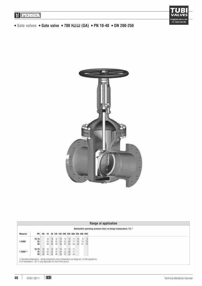
■ Gate valves ■ Gate valve ■ 700 HJ/JJ (GA ■ PN 10-40) ■ PN 10-100 ■ DN 50-150
Design Highlights
■ The main valve body is one-piece die-forged
incorporating the bonnet flange and the guide for the
shut-off device
■ Hard faced seats (valve body and shut-off device).
Hardness app. 35-37 HRC
■ Bolted bonnet with reduced shaft bolts
■ Full bore, except DN 65/50 and DN 125/100
■ Non - turning rising stem
■ Type GA, turning non-rising stem
Benefits
■ Die-forged parts, compared with cast steel parts are
generally free from porosity and shrink holes. The
special of the valve body minimizes the existance of
welding seams
■ Extremely resistant to wear
■ To improve the stress capability when temperature and
pressure fluctuate
■ No reduction in seat area
■ Minimum wear to the gland packing compared with
ground stem surfaces
■ Small dimensions
Standard features
■ Spit wedge = Type 700 JJ■ Flexible wedge = Type 700 HJ■ Die-forged body and bonnet■ Full bore,
exception DN 65/50 and DN 125/100■ Outside screw and yoke■ Non turning, rising stem■ Yoke sleeve ■ Available with flange and
buttweld ends
Option Version GA
■ Split wedge / Flexible wedge■ Inside screw■ Non-rising turning stem
Pressure and temperature ratings
■ Pressure rating up to 100 bar■ Acc. to PERSTA PD 10 up to 120 bar■ Temperature rating up to 600 °C
Materials
■ 1.0460■ 1.0619 just for flange type PN 10-40■ 1.0566■ 1.5415■ 1.7335■ 1.7383
Further materials on request
Media
Depending on the material the gate valves are suitable
for water, gas, oil and other non aggressive media
Fields of application
Chemical industries, power plants, ship building and
other

■ Gate valves ■ Gate valve ■ 700 HJ/JJ (GA ■ PN 10-40) ■ PN 10-100 ■ DN 50-150
Technical alterations reserved6100.1.08.1144
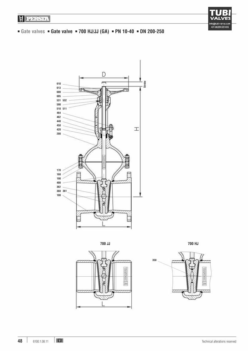
610
613
600
605
510
531
511
590
464
462
440
420
450
200
190
170
160
400
360
363
100
700 GA
361
Str
oke
■ Gate valves ■ Gate valve ■ 700 HJ/JJ (GA ■ PN 10-40) ■ PN 10-100 ■ DN 50-150
Pos. Component 1.0619 (11) 1.0460 (21) 1.0566 (25) 1.5415 (42) 1.7335 (44) 1.7383 (45)PN 10-40
100 Body 1.0619 1) 1.0460 1) 1.0566 1) 1.5415 2) 1.7335 2) 1.7383 2)
160 4Gasket Graphite 4) Graphite 4) Graphite 4) Graphite 4) Graphite 4) Graphite 4)
170 Stud 1.7709 1.7709 A4-70 1.7709 1.7709 1.7709190 Hexagonal nut 1.7218 1.7218 A4-70 1.7218 1.7218 1.7218200 Bonnet 1.0460 1.0460 1.0566 1.5415 1.7335 1.7383360/361 4Disc 1.0460 3) 1.0460 3) 1.0566 3) 1.5415 2) 1.7335 2) 1.7383 2)
363 Pressure piece 1.4021 1.4021 1.4021 1.4021 1.4021 1.4021400 4Stem 1.4021 1.4021 1.4571 1.4122 1.4122 1.4122420 4Packing Graphite Graphite Graphite Graphite Graphite Graphite440 Gland flange 1.0460 1.0460 1.4571 1.0460 1.0460 1.0460450 Grooved pin St St 1.4571 St St St462 Eye bolt 1.1181 1.1181 A4-50 1.1181 1.1181 1.1181464 Hexagonal nut 1.1181 1.1181 A4-70 1.1181 1.1181 1.1181510 4Yoke sleeve 1.0718 1.0718 1.0718 1.0718 1.0718 1.0718511 4Roller bearing WLSt WLSt WLSt WLSt WLSt WLSt531 Yoke nut 1.0718 1.0718 1.0718 1.0718 1.0718 1.0718590 Grease nipple 5.8 5.8 5.8 5.8 5.8 5.8600 Handwheel 0.7040 0.7040 0.7040 0.7040 0.7040 0.7040605 Key 1.0060 1.0060 1.0060 1.0060 1.0060 1.0060610 Hexagonal pipe nut St St St St St St613 Screw pin 45H 45H 45H 45H 45H 45H
4Spare parts
1) Welded on with Cr17 2) Welded on with Stellite 3) Welded on with 18/8 4) DN 150 grooved with graphite layer
Attention: Ki-Gate-Valve 700 GA only in material 1.0460
Materials
700 GA GS-C25N 700 GA
PN 10-25 40-100 10-40 63-100 10-40 63-100 10-25 40 10-25 40 63 100 10-40 63-100 10-25 40 10-40 KvsDN L L H H Stroke D D H1 FL FL FL FL FL FL BW BW FL FL BW (m3/h)
50 250 250 337 337 63 180 180 280 21,5 21,5 19,0 19,0 23,5 26,5 15,0 15,5 19,0 19,0 15,0 258,065 / 50 270 290 337 337 63 180 180 280 21,0 21,0 26,0 30,5 15,5 16,0 21,0 21,0 28,0 258,080 280 310 410 410 90 225 225 345 40,0 40,0 35,0 35,0 40,5 45,0 28,0 31,0 35,0 35,0 28,0 628,0100 300 350 455 505 110 280 360 405 57,0 61,5 50,0 54,0 63,0 71,0 43,0 47,0 50,0 54,0 43,0 991,0125 / 100 325 400 455 505 110 280 360 405 53,5 59,0 74,0 89,0 45,0 49,0 53,0 59,0 45,0 991,0150 350 450 655 685 165 360 450 525 114,0 120,0 92,0 98,0 138,0 155,0 80,0 100,0 92,0 98,0 80,0 2323,0
Dimensions/mm Weights/kg and Kvs-values
Technical alterations reserved 6100.1.08.11 45
■ Gate valves ■ Gate valve ■ 700 HJ/JJ (GA) ■ PN 10-40 ■ DN 200-250
Technical alterations reserved6100.1.08.1146
Admissible operating pressure [bar] at design temperature [°C] 1)
Material PN -60 -10 20 120 150 200 250 300 350 400 450
10-16 16 16 16 15 14 13 11 10 8 61.0460 25 25 25 25 24 22 20 17 16 13 10
40 40 40 40 38 35 32 28 24 21 10
10-16 16 16 16 16 15 14 13 111.0566 2) 25 25 25 25 25 24 22 20 17
40 40 40 40 40 38 35 32 28
1) Operating temperature = design temperature minus temperature surcharge acc. to DIN regulations.2) At temperature > 50 °C only applicable for short-time service.
Range of application

■ Gate valves ■ Gate valve ■ 700 HJ/JJ (GA) ■ PN 10-40 ■ DN 200-250
Design Highlights
■ Die-forged body and bonnet
■ Hard faced seats (valve body and shut-off device)
Hardness app. 35-37 HRC
■ Bolted bonnet with reduced shaft bolts
■ Full bore
■ Non-turning, rising stem
■ Type GA, rotating non-rising stem
■ Possibility to add an actuator-flange
Standard features
■ Split wedge = Type 700 JJ■ Flexible wedge = Type 700 HJ■ Die-forged body and bonnet■ Full bore■ Outside screw and yoke■ Non-turning rising stem■ Yoke sleeve ■ Available with flange and
buttweld ends
Optional standard features GA
■ Split wedge / Flexible wedge■ Inside screw■ Non-rising turning stem
Pressure and temperature ratings
■ Pressure rating up to 40 bar■ Temperature rating up to 450 °C
Benefits
■ Free from porosity and shrink holes
■ Extremely resistant to wear
■ To improve the stress capability when temperature and
pressure fluctuate
■ No reduction at seat area
■ Minimum wear to the gland packing compared
with ground stem surfaces
■ Small dimensions
■ Simple retrofitting of an actuator possible
Materials
■ 1.0460■ 1.0566
Further materials on request
Media
Depending on the material the gate valves are suitable
For water, gas, oil and other non aggressive media
Fields of application
Chemical industries, power plants, ship building and
other
Technical alterations reserved 6100.1.08.11 47
■ Gate valves ■ Gate valve ■ 700 HJ/JJ (GA) ■ PN 10-40 ■ DN 200-250
Technical alterations reserved6100.1.08.1148
610
613
600
605
531
590
510
464
462
440
450
420
200
170
160
190
400
362
360
100
532
700 JJ 700 HJ
511
361
350
Str
oke

■ Gate valves ■ Gate valve ■ 700 HJ/JJ (GA) ■ PN 10-40 ■ DN 200-250
Pos. Component 1.0460 (21) 1.0566 (25)
100 Body 1.0460 3) 1.0566 3)
160 4Gasket Grooved with Grooved withgraphite layer graphite layer
170 Stud 1.1181 A4-70190 Hexagonal nut 1.1181 A4-70200 Bonnet 1.0460 1.0566350 4Wedge 1.0460 4) 1.0566 4)
360/361 4Disc 1.8507 4) 1.0566 4)
362 4Ball WLSt WLSt400 4Stem 1.4021 5) 1.4571420 4Packing Graphite Graphite440 Gland flange 1.0460 1.4571450 Grooved pin St 1.4571462 Eye bolt 1.1181 A4-50464 Hexagonal nut 1.1181 A4-70510 Yoke sleeve 1.0718 1.0718511 4Needle bearing WLSt WLSt531 4Yoke nut 1.0718 1.0718532 Screw pin 45H 45H590 4Grease nipple 5.8 5.8600 Handwheel 0.7040 0.7040605 Key 1.0060 1.0060610 Hexagonal pipe nut St St613 Screw pin 45H 45H
4Spare parts
3) Welded on with 18/84) Welded on with Cr175) PN 40 DN 250 = 1.4122
Further materials on request.
Attention: Ki-Gate-Valve 700 GA only in material 1.0460
Materials
FL FL BW BW KvsDN PN 10-25 PN 40 PN 10-25 PN 40 (m3/h)
200 151,5 185 140 140 4000250 285,0 325 245 280 6247
700 GADN
200 138,5 170 125 125 4000250 263,0 303 223 258 6247
Weights/kg and Kvs-values
PN PN PN PN10-25 40 10-25 40
DN L L H Stroke D D
200 400 550 810 220 360 450250 450 650 975 285 450 450
700 GADN H1
200 590250 725
Dimensions/mm
Technical alterations reserved 6100.1.08.11 49
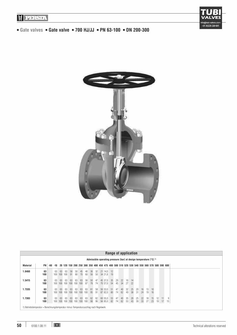
■ Gate valves ■ Gate valve ■ 700 HJ/JJ ■ PN 63-100 ■ DN 200-300
Technical alterations reserved6100.1.08.1150
Admissible operating pressure [bar] at design temperature [°C] 1)
Material PN -60 -10 20 120 150 200 250 300 350 400 450 475 480 500 510 520 530 540 550 560 570 580 590 600
1.0460 63 63 63 63 58 50 45 40 36 32 21 14,0 12100 100 100 100 91 80 70 60 56 50 34 21,8 19
1.5415 63 63 63 63 63 63 63 56 50 47 45 37,0 35 29 22 16 14100 100 100 100 100 100 100 87 78 74 70 57,0 54 45 34 27 22
1.7335 63 63 63 63 63 63 63 63 61 58 56 53,0 51 47 40 32 25 20 16 13 10100 100 100 100 100 100 100 100 95 91 87 82,0 80 74 62 49 38 31 24 19 16
1.7383 63 63 63 63 63 63 63 63 62 62 60 55,0 53 47 40 35 28 25 22 18 15 12 11 9100 100 100 100 100 100 100 100 98 96 94 85,0 82 74 62 53 43 39 33 27 23 19 17 15
1) Betriebstemperatur = Berechnungstemperatur minus Temperaturzuschlag nach Regelwerk.
Range of application

■ Gate valves ■ Gate valve ■ 700 HJ/JJ ■ PN 63-100 ■ DN 200-300
Standard features
■ Split wedge = Type 700 JJ■ Flexible wedge = Type 700 HJ■ Die-forged body and bonnet■ Full bore■ Outside screw and yoke■ Non-turning, rising stem■ Yoke sleeve■ Available with flange and
buttweld ends
Pressure and temperature ratings
■ Pressure rating up to 100 bar■ Temperature rating up to 600 °C
Materials
■ 1.0460■ 1.5415■ 1.7335■ 1.7383
For low temperature service available as casting.
Other materials on request.
Design Highlights
■ Die-forged body and bonnet
■ Hard faced seats (valve body and shut-off device)
■ Gasket located in gap
■ Full bore
■ Non-rising stem
Benefits
■ Free from porosity and shrink holes
■ Extremely resistant to wear
■ Blow out protection
■ No reduction in seat area
■ Minimum wear to the gland packing compared
with ground stem surfaces
Fields of application
Chemical industries, power plants, ship building and
other
Media
Depending on the material the gate valves are suitable
for water, gas, oil and other non aggressive media
Technical alterations reserved 6100.1.08.11 51
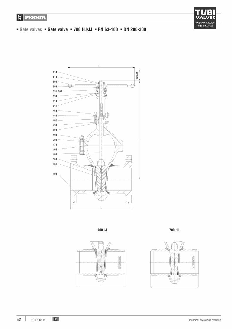
■ Gate valves ■ Gate valve ■ 700 HJ/JJ ■ PN 63-100 ■ DN 200-300
Technical alterations reserved6100.1.08.1152
700 JJ 700 HJ
Str
oke
613
610
600
605
531 532
590
510
511
464
440
462
450
420
190
200
170
160
400
360
361
100

■ Gate valves ■ Gate valve ■ 700 HJ/JJ ■ PN 63-100 ■ DN 200-300
Pos. Component 1.0460 (21) 1.5415 (42) 1.7335 (44) 1.7383 (45)
100 Body 1.0460 1.7383/1.5415 1.7383/1.7335 1.7383160 4Seat ring Grooved with Grooved with Grooved with Grooved with
graphite layer graphite layer graphite layer graphite layer170 Stud 1.7709 1.7709 1.7709 1.7709190 Hexagonal nut 1.7218 1.7218 1.7218 1.7218200 Bonnet 1.7383 1.7383 1.7383 1.7383360/361 4Disc 1.7383 4) 1.7383 1.7383 1)3) 1.8507 3)
400 4Stem 1.4021 1.4122 1.4122 1.4122420 4Packing Graphite Graphite Graphite Graphite440 Gland flange 1.0460 1.0460 1.0460 1.0460450 Grooved pin St 6) St 6) St 6) St 6)
462 Eye bolt 1.1181 5) 1.1181 5) 1.1181 5) 1.1181 5)
464 Hexagonal nut 1.1181 9) 1.1181 9) 1.1181 9) 1.1181 9)
510 4Yoke sleeve 1.0718 8) 1.0718 8) 1.0718 8) 1.0718 8)
511 4Roller bearing WLSt 7) WLSt 7) WLSt 7) WLSt 7)
531 Yoke nut 1.0718 1.0718 1.0718 1.0718532 Screw pin 45H 45H 45H 45H590 Grease nipple 5.8 5.8 5.8 5.8600 Handwheel St St St St605 Key 1.0060 1.0060 1.0060 1.0060610 Handwheel nut St St St St613 Screw pin 45H 45H 45H 45H
4Spare parts
1) DN 250 = 1.7383 welded on with Stellite2) welded on with Cr173) welded on with Stellite4) DN 250 = 1.0460 welded on with Cr175) DN 250 = 1.77096) DN 250 = 1.72187) DN 250 = Roller bearing8) DN 250 = CW 713 R9) DN 250 = 1.7218
Materials
FL FL BWPN PN PN Kvs
DN 63 100 63-100 (m3/h)
200 270 285 215 4000250 480 538 430 6247300 690 750 560 8997
Weights/kg and Kvs-values
PN 63-100
DN L H Stroke D
200 550 890 210 600250 650 1110 265 720300 750 1310 313 900
Dimensions/mm
Technical alterations reserved 6100.1.08.11 53

Technical alterations reserved6100.1.08.1154
■ Gate valves ■ Gate valve ■ 400 JJ ■ PN 63-100 ■ DN 350-700
Admissible operating pressure [bar] at design temperature [°C] 1)
Material PN -10 20 120 150 200 250 300 350 400 450 475 480 500 510 520 530 540 550 560 570 580 590 600
1.0425 63 63 63 63 58 50 45 40 36 32 21 14,0 12100 100 100 100 91 80 70 60 56 50 34 21,8 19
1.5415 63 63 63 63 63 63 63 56 50 47 45 37,0 35 29 22 16 14100 100 100 100 100 100 100 87 78 74 70 57,0 54 45 34 27 22
1.7335 63 63 63 63 63 63 63 63 61 58 56 53,0 51 47 40 32 25 20 16 13 10100 100 100 100 100 100 100 100 95 91 87 82,0 80 74 62 49 38 31 24 19 16
1.7383 63 63 63 63 63 63 63 63 62 62 60 55,0 53 47 40 35 28 25 22 18 15 12 11 9100 100 100 100 100 100 100 100 98 96 94 85,0 82 74 62 53 43 39 33 27 23 19 17 15
1) Operating temperature = design temperature minus temperature surcharge acc. to DIN regulations.
Range of application

Technical alterations reserved 6100.1.08.11 55
■ Gate valves ■ Gate valve ■ 400 JJ ■ PN 63-100 ■ DN 350-700
Standard features
■ Split wedge type■ Die-forged body and bonnet■ Outside screw and yoke■ Possibility to add an actuator
Pressure and temperature ratings
■ Pressure rating up to 100 bar■ Temperature rating up to 600 °C
Materials
■ 1.0425■ 1.5415■ 1.7335■ 1.7383
Media
Depending on the material the gate valves are suitable
for water, gas, oil and other non aggressive media
Fields of application
Chemical industries, power plants, ship building and
other
Design Highlights
■ Seats and wedge faced with stellite
■ Non-turning, rising stem
■ Gland flange and gland ring in two separate pieces
■ Yoke sleeve supported by needle bearing
Benefits
■ Best possible sliding performance, minimum wear
■ Minimum wear to the gland packing
■ Damage to the stem by irregular tightening of
gland bolts is avoided
■ Minimize the expenditure of effort
when operating valve
Technical alterations reserved6100.1.08.1156
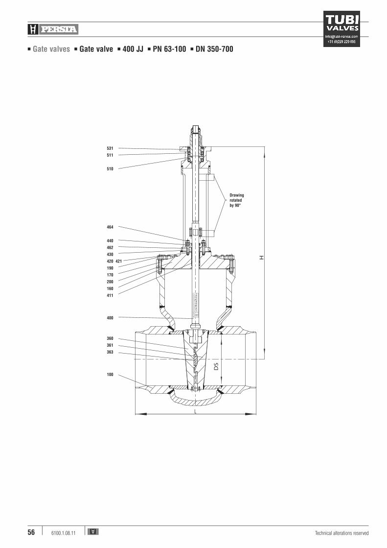
■ Gate valves ■ Gate valve ■ 400 JJ ■ PN 63-100 ■ DN 350-700
531
511
510
464
440
462
430
420 421
190
170
200
160
411
400
360
361
363
100
Drawing rotated by 90°

Technical alterations reserved 6100.1.08.11 57
■ Gate valves ■ Gate valve ■ 400 JJ ■ PN 63-100 ■ DN 350-700
Pos. Component 1.0425 (22) 1.5415 (42) 1.7335 (44) 1.7383 (45)
100 Body 1.0425 1.5415 1.7335 1.7383welded on with Stellite Stellite Stellite Stellite
160 4Gasket Graphite Graphite Graphite Graphite170 Stud 1.7709 1.7709 1.7709 1.7709190 Hexagonal nut 1.7218 1.7218 1.7218 1.7218200 Bonnet 1.0460 1.5415 1.7335 1.7383360/361 4Double disc 1.7383 1.7383 1.7383 1.7383
welded on with Stellite Stellite Stellite Stellite363 4Pressure piece 1.4122 1.4122 1.4122 1.4122400 4Stem 1.4021 1.4122 1.4122 1.4122411 4Guide bushing 1.8507 1.8507 1.8507 1.8507420/421 4Packing Graphite Graphite Graphite Graphite430 Gland ring 1.5415 1.5415 1.5415 1.5415440 Gland flange 1.5415 1.5415 1.7383 1.7383462 Stud 1.7709 1.7709 1.7709 1.7709464 Hexagonal nut 1.7218 1.7218 1.7218 1.7218510 4Yoke sleeve CW 713 R CW 713 R CW 713 R CW 713 R511 4Roller bearing WLSt WLSt WLSt WLSt531 Screwing 1.7335 1.7335 1.7335 1.7335
4Spare parts
Materials
KvsDN BW (m3/h)
350 950 11243400 1500 14521450 1850 18105500 2350 22353600 4300 32188700 5100 41773
Weights/kg and Kvs-values
DN DS Stroke L H
350 330 365 850 1620400 375 417 950 1745450 419 455 1050 2030500 464 515 1150 2260600 559 625 1350 2560700 640 690 1550 2695
Dimensions/mm
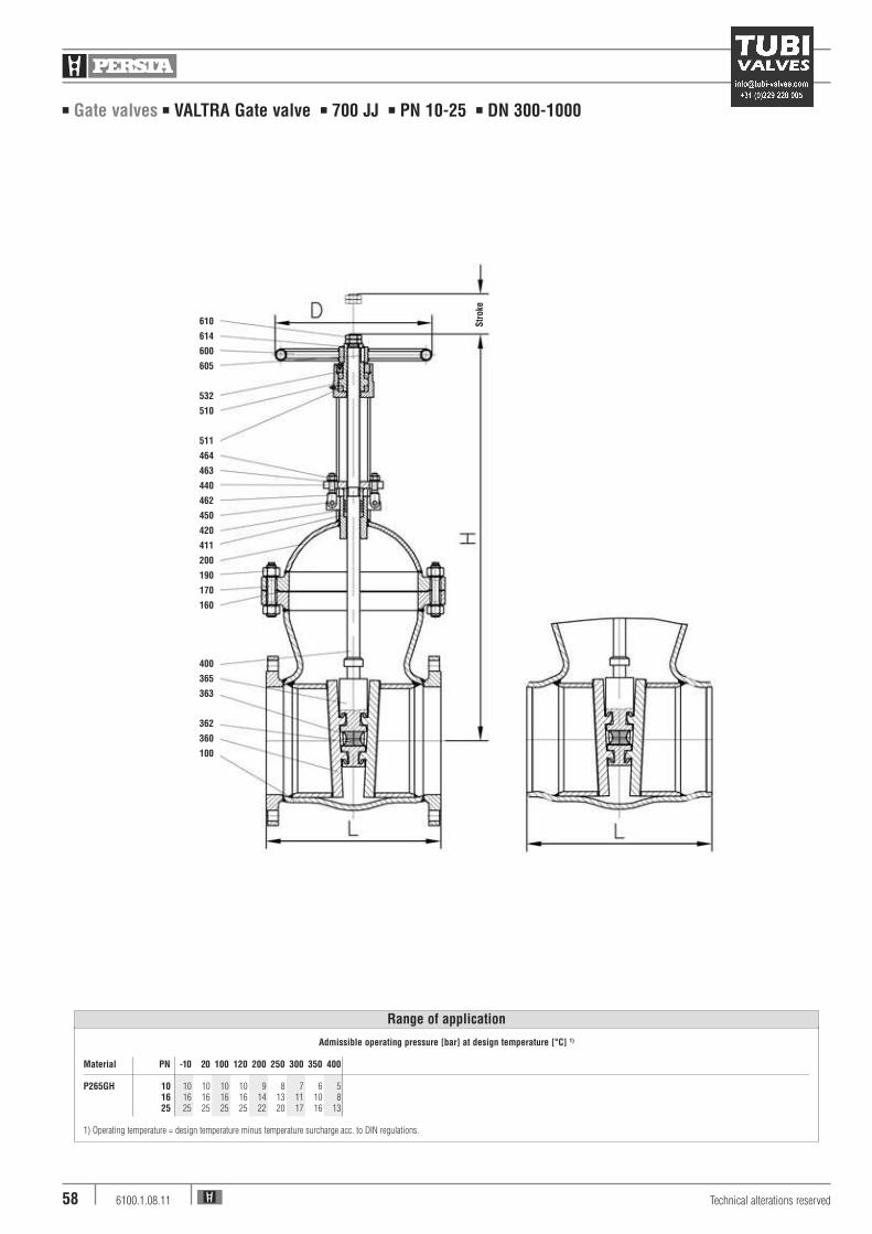
■ Gate valves ■ VALTRA Gate valve ■ 700 JJ ■ PN 10-25 ■ DN 300-1000
Technical alterations reserved6100.1.08.1158
610
614
600
605
532
510
511
464
463
440
462
450
420
411
200
190
170
160
400
365
363
362
360
100
Admissible operating pressure [bar] at design temperature [°C] 1)
Material PN -10 20 100 120 200 250 300 350 400
P265GH 10 10 10 10 10 9 8 7 6 516 16 16 16 16 14 13 11 10 825 25 25 25 25 22 20 17 16 13
1) Operating temperature = design temperature minus temperature surcharge acc. to DIN regulations.
Range of application
Str
oke

■ Gate valves ■ VALTRA Gate valve ■ 700 JJ ■ PN 10-25 ■ DN 300-1000
Pos. Component P265GH (22)
100 Body P265GHwelded on with X20CrMo171
160 4Gasket Sigraflex170 Stud 1.7158190 Hexagonal nut 1.7158200 Bonnet P265GH360 4Key P265GH
welded on with X8CrTi18362 4Ball 1.4021363 4Pressure piece 1.4021365 4Double disc guide P265GH400 4Stem 1.4021411 Guide bushing GG 25420 4Packing Graphite440 Gland flange P265GH450 Pin 1.1181462 Gland bolt 1.1181463 Washer St464 Hexagonal nut 1.0501510 4Yoke sleeve 0.7040511 4Thrust ball bearing WLSt531 Screwing S355J2G3532 Countersink screw 8.8600 Handwheel St605 Key 1.0050610 Hexagonal nut 5.6614 Retaining ring FSt
4Spare parts
Further materials on request.
Materials
PN PN PN PN PN PN10 16 25 10 16 25 Kvs
DN FL FL FL BW BW BW (m3/h)
300 320 330 360 295 295 315 9230350 390 405 445 360 360 380 11237400 540 560 610 500 500 525 14677500 815 860 945 765 765 850 23561600 1210 1270 1425 1170 1170 1285 33929700 1690 1715 1980 1630 1630 1775 46181800 2410 2440 2750 2330 2330 2500 603189001000
Weights/kg and Kvs-values
PN PN PN PN PN 10-25 10-25 10-16 25 10-25
DN L H Stroke Stroke D
300 500 1165 345 345 450350 550 1260 375 375 500400 600 1410 420 420 600500 700 1715 545 545 800600 800 2035 635 655 800700 900 2260 790 800800 1000 2690 845 8009001000
Dimensions/mm
Technical alterations reserved 6100.1.08.11 59
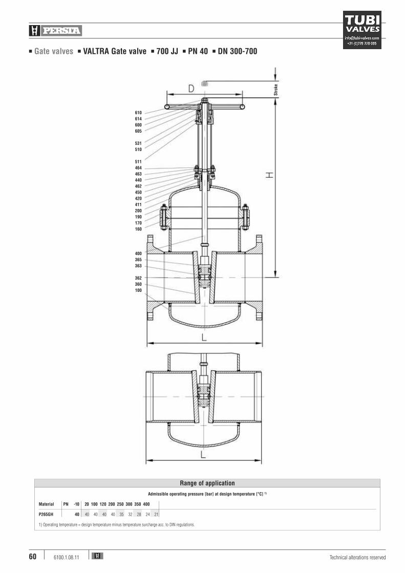
■ Gate valves ■ VALTRA Gate valve ■ 700 JJ ■ PN 40 ■ DN 300-700
Technical alterations reserved6100.1.08.1160
610
614
600
605
531
510
511
464
463
440
462
450
420
411
200
190
170
160
400
365
363
362
360
100
Admissible operating pressure [bar] at design temperature [°C] 1)
Material PN -10 20 100 120 200 250 300 350 400
P265GH 40 40 40 40 40 35 32 28 24 21
1) Operating temperature = design temperature minus temperature surcharge acc. to DIN regulations.
Range of application
Str
oke

■ Gate valves ■ VALTRA Gate valve ■ 700 JJ ■ PN 40 ■ DN 300-700
Pos. Component P265GH (22)
100 Body P265GHwelded on with X20CrMo171
160 4Gasket Sigraflex170 Tension screw 1.7158190 Hexagonal nut 1.7158200 Bonnet P265GH360 4Key P265GH
welded on with X8CrTi18362 4Ball 1.4021363 4Pressure piece 1.4021365 4Double disc guide P265GH400 4Stem 1.4021411 Guide bushing GG 25420 4Packing Graphite440 Gland flange P265GH450 Pin 1.1181462 Gland bolt 1.1181463 Washer St464 Hexagonal nut 1.0501510 4Yoke sleeve 0.7040511 4Thrust ball bearing WLSt531 Screwing S355J2G3532 Countersink screw 8.8600 Handwheel St605 Key 1.0050610 Hexagonal nut 5.6614 Retaining ring FSt
4Spare parts
Further materials on request.
Materials
KvsDN FL BW (m3/h)
300 440 370 9230350 610 460 11237400 890 710 14677500 1270 1050 23561600 2310 1980 33929700 3210 2960 46181800
Weights/kg and Kvs-values
DN L H Stroke D
300 750 1260 345 500350 850 1295 375 600400 950 1575 445 800500 1150 1795 525 800600 1350 2155 640 800700 1550 2595 770 800800
Dimensions/mm
Technical alterations reserved 6100.1.08.11 61
■ Gate valves ■ Gate valve ■ 700 JJ ■ PN 160 / PD 18 ■ DN 50-300/250
Technical alterations reserved6100.1.08.1162
FL- Admissible operating pressure [bar] at design temperature [°C] 1)
VersionMaterial PN -10 20 120 150 200 250 300 350 400 450 500 510 520 530 540 550
1.5415 160 160 160 160 160 160 160 139 125 118 112 72 55 43 351.7335 160 160 160 160 160 160 160 160 153 146 139 118 100 79 62 46 351.7383 160 160 160 160 160 160 160 160 153 146 139 118 100 79 70 61 52
1) Operating temperature = design temperature minus temperature surcharge acc. to DIN regulations.
Range of application
BW- Admissible operating pressure [bar] at design temperature [°C] 1)
VersionMaterial PD 20 50 100 120 150 200 250 300 350 400 420 430 440 460 470 480 490 500 510 520 530 540 550 560 570 580 590 600
1.5415 18 258 246 229 219 204 185 170 146 141 136 134 133 132 130 129 128 112 88 67 53 421.7335 18 258 249 234 228 219 205 194 180 170 161 156 155 153 150 149 148 147 133 112 89 72 58 46 37 301.7383 18 258 250 239 233 224 210 205 194 180 170 166 164 162 159 156 155 153 131 115 100 88 76 66 56 50 43 37 33
1) Operating temperature = design temperature minus temperature surcharge acc. to DIN regulations.

■ Gate valves ■ Gate valve ■ 700 JJ ■ PN 160 / PD 18 ■ DN 50-300/250
Design Highlights
■ Die-forged valve body with incorporated seats
■ Seats and wedge faced with stellite
■ Non-rising handwheel
■ Non-turning, rising stem
■ Hammer head connection between wedge and stem
■ Gland ring and gland flange in two separate pieces
■ Yoke sleeve supported at the top and at the bottom by
means of needle bearings (axial type)
■ Valve head equipped with dirt scrapers below and
above the bearings
Benefits
■ Free from porosity and shrink holes
■ Best possible sliding performance, minimum wear
■ Small dimensions
■ Minimum wear to the gland packing
■ The wedges are able to move parallel to the axis of the
pipeline within the guiding groove. This protects the
stem against bending moments
■ Damage to the stem by irregular tightening of gland
bolts is avoided
■ To minimize the expenditure of effort when opening
and closing the valve
■ To protect against dirt and to avoid the loss
of lubricants
Standard features
■ Die-forged body■ Flexible wedge■ Incorporated seats■ Outside screw■ Gasket located in a groove■ Yoke sleeve with needle bearings■ Universal valve head for mounting actuators
Pressure and temperature ratings
■ Pressure rating BW up to 233 bar (PD 18)■ Pressure rating FL up to 160 bar■ Temperature ratings up -10 °C to 600 °C
Materials
■ 1.5415■ 1.7335■ 1.7383
Further materials, e.g. F92 on request
Media
Depending on the material the gate valves are suitable
for water, gas, oil and other non aggressive media
Fields of application
Chemical industries, power plants, ship building and
other
Technical alterations reserved 6100.1.08.11 63

■ Gate valves ■ Gate valve ■ 700 JJ ■ PN 160 / PD 18 ■ DN 50-300/250
Technical alterations reserved6100.1.08.1164
610
613
600
605
540
553
542
510
511
552
464
440
462
430
420
412
200
190
410
170
160
400
100
360
361
363
421S
troke
Version DN 50 - 80
■ Gate valves ■ Gate valve ■ 700 JJ ■ PN 160 / PD 18 ■ DN 50-300/250
Pos. Component 1.5415 (42) 1.7335 (44) 1.7383 (45)
100 Body 1.5415 1) 1.7383/1.7335 1) 1.7383 1)
160 4Gasket Grooved with Grooved with Grooved withgraphite layer graphite layer graphite layer
170 Stud 1.7709 1.7709 2) 1.7709 2)
189 Expansion shaft -- 1.7709 2) 1.7709 2)
190 Hexagonal nut 1.7218 1.7218 1.7218200 Bonnet 1.7383 1.7383 1.7383360/361 4Double disc 1.7383 1) 1.7383 1) 1.7383 1)
363 4Pressure piece 1.4122 1.4122 1.4122400 4Stem 1.4923 1.4923 1.4923410 Back seat bushing 1.4006 1.4006 1.4006412 Bottom ring 1.0718 1.0718 1.0718420/421 4Packing Graphite Graphite Graphite430 Gland ring 1.5415 1.5415 1.5415440 Gland flange 1.5415 1.5415 1.5415450 Rivet pin 1.7218 1.7218 1.7218462 Eye bolt 1.7709 1.7709 1.7709464 Hexagonal nut 1.7218 1.7218 1.7218510 4Yoke sleeve CW 713 R CW 713 R CW 713 R511 4Roller bearing WLSt WLSt WLSt540 Flange 1.0425 1.0460 1.0460542 Headcap screw 8.8 8.8 8.8552/553 4Gasket NBR Viton Viton590 Grease nipple 5.8 5.8 5.8600 Handwheel St St St605 Key 1.0060 1.0060 1.0060610 Hexagonal pipe nut St St St613 Screw pin 45H 45H 45H
4Spare parts
1) Welded on with Stellite
2) Working temperature > 550 °C = Material 1.4923
Materials
KvsDN FL BW (m3/h)
50 60 45 22865 / 50 66 5280 116 100 565100 148 125 930125 / 100 165 130150 320 270 1995200 610 520 3458250 1050 930 5367300 / 250 1180 980 5041
Weights/kg and Kvs-values
DN L H Stroke D
50 300 490 80 35065 / 50 360 490 80 35080 390 610 105 400100 450 695 130 500125 / 100 525 695 130 500150 600 890 185 800200 750 1090 235 1000250 900 1275 265 1000300 / 250 1050 1275 265 1000
Dimensions/mm
Technical alterations reserved 6100.1.08.11 65


![6SUDZR]GDQLH ] HJ]DPLQX PDWXUDOQHJR :2-(:Ï'=7:2 0$à232/6.,( · 6sudzr]gdqlh ] hj]dplqx pdwxudoqhjr 3u]helhj hj]dplqx 7dehod ,qirupdfmh grw\f] fh su]helhjx hj]dplqx 7huplq hj]dplqx](https://img.dokumen.tips/doc/110x75/5f5168b426368d37502f266e/6sudzrgdqlh-hjdplqx-pdwxudoqhjr-2-72-02326-6sudzrgdqlh-hjdplqx.jpg)