Embed Size (px)
Citation preview

Gate-Style DEMCO ValvesDependability, inline repairability, flexible trim options, and drop-tight position shutoff
ContentsIntroduction � � � � � � � � � � � � � � � � � � � � � � � � � � � � � � � � � � � � � � � � � � � � � � � � � � � � � � � � � � � � � � � � � � � � � � � � � � � � � � � � 3Series DM gate valves � � � � � � � � � � � � � � � � � � � � � � � � � � � � � � � � � � � � � � � � � � � � � � � � � � � � � � � � � � � � � � � � � � � 4Product specifications � � � � � � � � � � � � � � � � � � � � � � � � � � � � � � � � � � � � � � � � � � � � � � � � � � � � � � � � � � � � � � � � � � � 5
Dimensions, materials, and parts listSeries DM gate valves
7,500-psi working pressure (WP) � � � � � � � � � � � � � � � � � � � � � � � � � � � � � � � � � � � � � � � � � � � � � � � � � � 65,000-psi WP � � � � � � � � � � � � � � � � � � � � � � � � � � � � � � � � � � � � � � � � � � � � � � � � � � � � � � � � � � � � � � � � � � � � � � � � � � 14ASME Class 600 � � � � � � � � � � � � � � � � � � � � � � � � � � � � � � � � � � � � � � � � � � � � � � � � � � � � � � � � � � � � � � � � � � � � � � 22ASME Class 900 � � � � � � � � � � � � � � � � � � � � � � � � � � � � � � � � � � � � � � � � � � � � � � � � � � � � � � � � � � � � � � � � � � � � � � 24ASME Class 1500 � � � � � � � � � � � � � � � � � � � � � � � � � � � � � � � � � � � � � � � � � � � � � � � � � � � � � � � � � � � � � � � � � � � � 26
Series DMA gate valve7,500-psi WP—automated � � � � � � � � � � � � � � � � � � � � � � � � � � � � � � � � � � � � � � � � � � � � � � � � � � � � � � � � 305,000-psi WP—automated � � � � � � � � � � � � � � � � � � � � � � � � � � � � � � � � � � � � � � � � � � � � � � � � � � � � � � � � 38
2

Introduction
Oklahoma City, Oklahoma, USA.
Cameron is a leading provider of valves, valve automation, and measurement systems to the oil and gas industry. Our products are primarily used to control, direct, and measure the flow of oil and gas as it is moved to refineries, petrochemical plants, and industrial centers for processing.
We provide valve products that are sold through distributor networks worldwide� Our products are used in oil and gas and industrial applications and include widely recognized brands such as DEMCO* valves; NAVCO* floating ball valves; NEWCO* gate, globe, and check valves; DOUGLAS CHERO* forged-steel gate, globe, and check valves; NUTRON* ball valves; TOM WHEATLEY* check valves; WHEATLEY* check valves; and WKM* valves�
Designed for dependable, heavy-duty performance in abrasive and corrosive service conditions, butterfly-style DEMCO valves are commonly selected for a number of oilfield applications, including drilling and production�
3

Series DM Gate ValvesSeries DM gate valves, the premier gate valve in the oil and gas drilling market, are specifically engineered for the rigorous requirements of oilfield applications� Designed for dependable, heavy-duty performance in abrasive service conditions, Series DM gate valves are commonly selected for a number of oilfield applications, including
■ drilling standpipe manifold ■ pump manifold block valves ■ high-pressure mud mixing lines ■ high-pressure drilling system block valves�
The Series DM gate valves are available in ASME Classes 600, 900, and 1500� They also are available in 5,000-psi gauge pressure and 7,500-psi gauge pressure (not API monogrammed)�
Features and benefitsInline field repairabilityThe bonnet is easily removed for internal parts inspection, replacement, or both without removing the valve from the line� This design simplicity permits fast and easy service without the need for special tools�
Flexible trim offeringsOptional materials for stems, gates, seat inserts, and seat elastomers make it easier to trim valves for a wide range of service conditions�
AutomationAutomation is available for 5,000- and 7,500-psi pressure-rated valves�
Exclusive seats design for drop-tight sealingThe Series DM gate valve seats use an unique design to provide a drop-tight shutoff in abrasive and erosive service�
The valves conform to ■ American Bureau of Shipping (ABS) ■ Det Norske Veritas (DNV) ■ NACE MR0175�
Series DM 7500The seat consists of two identical metal wear rings encapsulated in elastomer to form a cylindrical shape with a gate slot and two round ports� The closed gate bears on the downstream wear ring, and the elastomer provides a drop-tight pressure-responsive seal around the port�
Series DM 5000, Class 600, 900, 1500The cylindrical seat assembly fits into the machined body cavity and is expanded outward toward the valve ports by the bonnet and spread ring in the bottom of the seat� The expansion occurs when the bonnet is tightened onto the body while engaging the seat pin extensions from both wear rings� The spread ring ensures the seat elastomer presses uniformly against the body bore� This design ensures that the seat seals tight against the body and around each valve port� This design has proved to be effective even if the gate and seat ring become scored or abraded during service� When it comes time for maintenance, the seat’s single-piece design makes it easy to pull out of the body for replacement�
5-in [130-mm] 7,500-psi WP Series DM gate valve.
5-in [130-mm] 5,000-psi WP Series DMA gate valve.
4

DM Series Pressure Classes and SizesPort Size, in [mm] Pressure Classes
600 900 1500 5000 7500Full port (FP) 2 [50] ● ● ● ●
21/2 [65] ● ● ●
3 [80] ● ● ● ● ●
4 [100] ● ● ● ● ●
5 [125] ● ●
6 [150] ● ●
Reduced port (RP)
2 × 11/2 [50 × 40] ●
21/2 × 2 [65 × 50] ●
3 × 2 [80 × 50] ●
4 × 3 [100 × 80] ● ●
5 × 4 [125 × 100] ● ●
6 × 4 [150 × 100] ●
6 × 5 [150 × 125] ● ●
8 × 6 [200 × 150] ●
Product SpecificationsSeries DM gate valve general technical informationValve size designations and weld end dimensional informationAll references to pipe size in this catalog are the nominal size� The actual OD and ID for various nominal sizes and schedules are tabulated below� Weld end bodies are machined at each end to match the pipe OD and ID�
Quality, inspections, and testing ■ The Cameron quality system is based on ISO 9000 and API Spec Q1
requirements and is ISO 9001:2008 certified� Cameron monitors all phases of valve production, from material receipt to final inspection, including liaising with third-party inspectors and certifying authorities�
All gate-style DEMCO valves are hydrostatically tested; stem seal, body, and seat are inspected for zero leakage under pressure before being released for shipment� Hydrotest specifications are based upon the latest-edition API Spec 6A testing requirements; Series DM 7500 Groups 2 and 3 valves undergo additional test cycles, including low-pressure seat tests prior to being released for shipment�
■ Group 1—Basic valve� Hydrostatic shell test—11,250 psi for 3 min� Hydrostatic seat test—7,500 psi for 3 min, each side� Material traceability on body and bonnet�
■ Group 2—Same as Group 1, except hydrostatic shell test—11,250 psi for 3 min, drop to 0 psi, then 11,250 psi for 15 min� Test is charted� Hydrostatic seat test—7,500 psi for 3 min, drop to 0 psi, 7,500 psi for 15 min, drop to 0 psi, then 300 psi for 5 min, each side� Test is charted� Material traceability on body, bonnet, stem, and bolting� Impact tests at or below −50 degF [−46 degC] on body, bonnet, stem, and bolting� Surface nondestructive examination (NDE) on body, bonnet, and stem�
■ Group 3—Same as Group 2, plus volumetric NDE on body and bonnet�
Seat seal options ■ Buna-N (nitrile) is excellent for petroleum oil and gases, fuel oils, and
alcohols from –10 to 200 degF [–23 to 93 degC]� ■ FKM is highly resistant to mineral acids and hydrocarbons, and is
serviceable from –10 to 400 degF [–23 to 204 degC]; not suitable for steam�
■ HNBR is formulated for use with synthetic and oil-based drilling mud service from –20 to 250 degF [–29 to 121 degC]�
Ordering information ■ Give pipe size, pressure class, and end connection� ■ Specify pressure class of flanged ends, raised face (RF), or ring type
joint (RTJ)� ■ For threaded ends, provide type of pipe:
● nonupset tubing (TBG)
● long casing thread (LCSG)
● external upset tubing (UPTBG)
● short casing thread (CSG)� ■ For weld ends, give schedule of mating pipe�
Nominal Size, in [mm]
OD IDSch. 40 Sch. 80 Sch. 160 XXH
11/2 [40] 1.900 1.610 1.500 – –
2 [50] 2.375 2.067 1.939 1.687 1.503
21/2 [65] 2.875 2.469 2.323 2.125 1.771
3 [80] 3.500 3.068 2.900 2.624 2.300
4 [100] 4.500 4.026 3.826 3.438 3.152
5 [125] 5.563 – 4.813 4.313 4.063
6 [150] 6.625 6.065 5.761 5.187 4.897
Series DM Gate Valves/Product Specifications
5

Series DM gate valves—7,500-psi WP2-in [50-mm] seat port
Dimensional Data and WeightsDimension Valve Seat Port Size for 7,500-psi WP: 2 in [50 mm] A, length, in [mm] Weld end 9.00 [229]
Flanged end, API length 20.50 [521]
Hammer union end 15.74 [400]
For flanged ends API ring number BX-152
Flange ID, in [mm] 2.00 [50]
Flange OD, in [mm] 7.88 [200]
Flange bolts, amount; in [mm] 8; 3/4 [19]
Weight, lbm [kg] Weld end 83 [38]
Flanged end 144 [65]
Hammer union end 101 [46]
Number of handle turns from open to closed 8.6
B, height, center to top (open), in [mm] 13.04 [331]
C, handle diameter, in [mm] 14.00 [356]
Dimensions, Materials, and Parts List
C
B
A
4
14
18
20
19
12
11
3 16 13 23
6

Series DM gate valves—7,500-psi WP
Parts ListRepair Kit
Key No.
Qty. Description Valve Seat Port Size for 7,500-psi WP: 2 in [50 mm] Repair Kit Component Part NumbersGroup 1 Group 2 Group 3
Assembly Base Number—NACE Compliant J025088 J025103 J0251041 1 Body ASTM A487 Gr. 4 Class D –2 1 Bonnet 4130 –
■ ● 3 1 Gate 41XX with quench, polish, quench (QPQ) nitriding 2171111-01410 SS with QPQ nitriding 2139624-02
■ ● 4 1 Gate clip 3XX SS M4504805 1 Handle ASTM A536 Gr. 65-45-12 –6 4 Heavy hex nut, 1-8 UNC ASTM A194 Gr. 2H ASTM A194 Gr. 7 –7 2 Heavy hex nut, 3/4-10 UNC ASTM A194 Gr. 2H ASTM A194 Gr. 7 –8 1 Housing ASTM A350 Gr. LF2 Class 1 J0249829 1 Lock handle CD 1213/15 –10 1 Lubricating nipple, 1/8 NPT Steel –
■ 11 1 O-ring, AS-568-210, secondary seal HNBR 2712425-13FKM J005531-210
■ 12 1 O-ring, AS-568-224, housing seal Buna-N J005526-224■ ● 13 2 O-ring, AS-568-229, wear ring seal HNBR 2712425-03
FKM J005521-229■ ● 14 1 O-ring, AS-568-342, bonnet seal HNBR 2712425-60
FKM J005521-34215 1 Retainer CD 1213/15 17-4PH SS –
■ ● 16 1 Seat assembly 410 SS with QPQ nitriding and HNBR 2139742-01410 SS with QPQ nitriding and FKM 2139741-02
17 1 Split pin, 3/16 in × 13/4 in [5 × 45] Steel –■ 18 1 Stem 410 SS J024983-107■ 19 1 Stem screw CD 1213/15 J001913■ 20 1 Stem seal assembly with bushing HNBR and bronze JN23231-008
FKM and bronze JN23231-00621 4 Stud (double ended), 1-8 UNC × 4.50 (long) ASTM A193 Gr. B7 ASTM A193 Gr. L7 –22 2 Stud (double ended), 3/4-10 UNC × 3.00 (long) ASTM A193 Gr. B7 ASTM A193 Gr. L7 –
■ ● 23 2 Wear ring 41XX with QPQ nitriding M452267410 SS 2139647-02
■ Major repair kit J025177-10274—one each for one year of service.● Minor repair kit J025177-00274.Major and minor repair kits listed for trim option J0XXXXX-XX72140 (410 SS stem, 41XX with QPQ gate, HNBR seat and seals).Consult Cameron for other repair kit trim options.
J025088-3 7 7 2 1 4 0Assembly Base Number 2 in [50 mm], Group 1
Assembly Part Number Example
End ConnectionNo. DescriptionFlanged
3 10,000 RTJ
Weld2 2.00-in [50 mm] XXH
4 3.00-in [80-mm] OD × 2.00-in [50-mm] ID
Hammer union9 2.00-in [50-mm] XXH 1502
hammer union
Seat and Seal ElastomerNo. Description2 FKM and FKM
4 HNBR and HNBR
Ring Groove InlayNo. Description0 –
1 316 SS inlay†
2 625 SS inlay†
† Inlay only available on flanged valves.
Seat Ring MaterialNo. Description1 410 SS
Gate and Wear Ring MaterialNo. Description2 41XX and 41XX
7 410 SS and 410 SS
Stem MaterialNo. Description7 410 stainless
steel (SS)
Body ConfigurationNo. Description5 Weld
7 Flanged
9 Hammer union
End connection Stem material
Gate and wear ring material
Seat ring material
Seat and seal elastomerRing groove inlay
7

Series DM gate valves—7,500-psi WP3-in [80-mm] seat port
Dimensional Data and WeightsDimension Valve Seat Port Size for 7,500-psi WP: 3 in [80 mm] A, length, in [mm] Weld end 13.00 [330]
Flanged end 24.38 [619]
Hammer union end 4 in 24.62 [625]
3 in 18.88 [480]
For flanged ends API ring number BX-154
Flange ID, in [mm] 3.00 [80]
Flange OD, in [mm] 10.62 [270]
Flange bolts, amount; in [mm] 8; 1 [25]
Weight, lbm [kg] Weld end 185 [84]
Flanged end 299 [136]
Hammer union end 4 in 269 [122]
3 in 211 [96]
Number of handle turns from open to closed 16.0
B, height, center to top (open), in [mm] 20.48 [520]
C, handle diameter, in [mm] 24.00 [610]
C
B
A
5
15
12
25, 26
13
22
23
20
4 18 14 27
8

Series DM gate valves—7,500-psi WP
Parts ListRepair Kit
Key No.
Qty. Description Valve Seat Port Size for 7,500-psi WP: 3 in [80 mm] Repair Kit Component Part NumbersGroup 1 Group 2 Group 3
Assembly Base Number—NACE Compliant J025299 J025300 J0253011 1 Body ASTM A487 Gr. 4 Class D –2 1 Bonnet 4130 –3 4 Capscrew socket head, 1/2 UNC × 1.50 (long) ASTM A574 Alloy Steel 18-8 SS –
■ ● 4 1 Gate 41XX with QPQ nitriding 2171112-01410 SS with QPQ nitriding 2139628-02
■ ● 5 1 Gate clip 3XX SS M4505056 1 Handle ASTM A536 Gr. 65-45-12 –7 1 Handle screw CD 1018/26 –8 12 Heavy hex nut, 1-8 UNC ASTM A194 Gr. 2H ASTM A194 Gr. 7 –9 1 Housing HR 1018/22 –10 4 Hex head bolt, 1/2-13 UNC × 3.00 (long) SAE International steel Gr. 5 –11 1 Lubricating nipple, 1/8 NPT Steel –
■ 12 1 O-ring, AS-568-214, secondary seal HNBR 2712425-01FKM J005531-214
■ 13 1 O-ring, AS-568-224, housing seal Buna-N J005526-224■ ● 14 2 O-ring, AS-568-340, wear ring seal HNBR 2712783-03
FKM J005521-340■ ● 15 1 O-ring, AS-568-361, bonnet seal HNBR 2712787-07
FKM J005521-36116 1 Relief fitting, 1/8 NPT Steel –17 1 Retainer HR 1018/22 17-4PH SS –
■ ● 18 1 Seat assembly 410 SS with QPQ nitriding and HNBR 2139744-01410 SS with QPQ nitriding and FKM 2139743-02
19 1 Sight tube Clear acrylic –■ 20 1 Stem 410 SS 213597-01
21 1 Stem cap ASTM A536 Gr. 65-45-12 –■ 22 1 Stem screw CD 1018/26 213600-01■ 23 1 Stem seal assembly with bushing HNBR and bronze JN01951-008
FKM and bronze JN01951-00624 12 Stud (double ended), 1-8 UNC × 4.50 (long) ASTM A193 Gr. B7 ASTM A193 Gr. L7 –
■ 25 2 Thrust needle roller bearing Hardened steel 50315432■ 26 4 Thrust washer Hardened steel 50315409■ ● 27 2 Wear ring 41XX with QPQ nitriding M452571
410 SS 2139648-02■ Major repair kit J025177-11374—one each for one year of service.● Minor repair kit J025177-00374.Major and minor repair kits listed for trim option J0XXXXX-XX72140 (410 SS stem, 41XX with QPQ gate, and HNBR seat and seals).Consult Cameron for other repair kit trim options.
J025299-3 7 7 2 1 2 1Assembly Base Number 3 in [80 mm], Group 1
Assembly Part Number Example
End ConnectionNo. DescriptionFlanged
3 10,000 RTJ
Weld2 3.00-in [80-mm] XXH
4 4.00-in [100-mm] XXH
5 4.50-in [114-mm] OD × 2.96-in [75-mm] ID
Hammer union8 3.00-in [80-mm] XXH 1502
hammer union
9 4.00-in [100-mm] XXH 1502 hammer union
Seat and Seal ElastomerNo. Description2 FKM and FKM
4 HNBR and HNBR
Ring Groove InlayNo. Description0 –
1 316 SS inlay†
2 625 SS inlay†
† Inlay only available on flanged valves.
Seat Ring MaterialNo. Description1 410 SS
Gate and Wear Ring MaterialNo. Description2 41XX and 41XX
7 410 SS and 410 SS
Stem MaterialNo. Description7 410 SS
Body ConfigurationNo. Description5 Weld
7 Flanged
9 Hammer union
End connection Stem material
Gate and wear ring material
Seat ring material
Seat and seal elastomerRing groove inlay
9

Series DM gate valves—7,500-psi WP4-in [100-mm] seat port
Dimensional Data and WeightsDimension Valve Seat Port Size for 7,500-psi WP: 4 in [100 mm] A, length, in [mm] Weld end 16.00 [406]
Flanged end 26.38 [670]
Hammer union end 5 in 25.62 [651]
4 in 27.62 [702]
For flanged ends API ring number BX-155
Flange ID, in [mm] 4.00 [100]
Flange OD, in [mm] 12.44 [316]
Flange bolts, amount; in [mm] 8; 11/8 [29]
Weight, lbm [kg] Weld end 281 [127]
Flanged end 456 [207]
Hammer union end 5 in 379 [172]
4 in 365 [166]
Number of handle turns from open to closed 21.3
B, height, center to top (open), in [mm] 27.53 [699]
C, handle diameter, in [mm] 24.00 [610]
C
B
A
5
15
20
12
25, 26
13
22
23
4 14 2718
10

Series DM gate valves—7,500-psi WP
Parts ListRepair Kit
Key No.
Qty. Description Valve Seat Port Size for 7,500-psi WP: 4 in [100 mm] Repair Kit Component Part NumbersGroup 1 Group 2 Group 3
Assembly Base Number—NACE Compliant J025102 J025107 J0251081 1 Body ASTM A487 Gr. 4 Class D –2 1 Bonnet 4130 –3 4 Capscrew socket head, 5/8 UNC × 1.75 (long) ASTM A574 Alloy Steel 18-8 SS –
■ ● 4 1 Gate 41XX with QPQ nitriding 2171267-01410 SS with QPQ nitriding 2139637-02
■ ● 5 1 Gate clip 3XX SS M4505056 1 Handle ASTM A536 Gr. 65-45-12 –7 1 Handle screw CD 1018/26 –8 10 Heavy hex nut, 11/8-8 UNC ASTM A194 Gr. 2H ASTM A194 Gr. 7 –9 4 Hex head bolt, 5/8-11 UNC × 3.50 (long) SAE steel Gr. 5 –10 4 Housing HR 1018/22 –11 1 Lubricating nipple, 1/8 NPT Steel –
■ 12 1 O-ring, AS-568-216, secondary seal HNBR 2726268-01FKM J005531-216
■ 13 1 O-ring, AS-568-228, housing seal Buna-N J005526-228■ ● 14 2 O-ring, AS-568-349, wear ring seal HNBR 2712787-04
FKM J005521-349■ ● 15 1 O-ring, AS-568-364, bonnet seal HNBR 2712426-11
FKM J005521-36416 1 Relief fitting, 1/8 NPT Steel –17 1 Retainer HR 1018/22 17-4PH SS –
■ ● 18 1 Seat assembly 410 SS with QPQ nitriding and HNBR 2139746-01410 SS with QPQ nitriding and FKM 2139745-02
19 1 Sight tube Clear acrylic –■ 20 1 Stem 410 SS 2140684-01
21 1 Stem cap ASTM A536 Gr. 65-45-12 –■ 22 1 Stem screw CD 1018/26 J019159■ 23 1 Stem seal assembly with bushing HNBR and bronze JN15853-008
FKM and bronze JN15853-00624 10 Stud (double ended), 11/8-8 UNC × 5.50 (long) ASTM A193 Gr. B7 ASTM A193 Gr. L7 –
■ 25 2 Thrust needle roller bearing Hardened steel J050911-005■ 26 4 Thrust washer Hardened steel J050911-006■ ● 27 2 Wear ring 41XX with QPQ nitriding M452290
410 SS 2139649-02■ Major repair kit J025177-10474—one each for one year of service.● Minor repair kit J025177-00474.Major and minor repair kits listed for trim option J0XXXXX-XX72140 (410 SS stem, 41XX with QPQ gate, and HNBR seat and seals).Consult Cameron for other repair kit trim options.
J025102-3 7 7 2 1 4 2Assembly Base Number 4 in [100 mm], Group 1
Assembly Part Number Example
End ConnectionNo. DescriptionFlanged
3 10,000 RTJ
Weld2 4.00-in [100-mm] XXH
3 5.00-in [125-mm] XXH
4 5.81-in [148-mm] OD × 4.06-in [103-mm] ID
5 6.00-in [152-mm] OD × 4.00-in [100-mm] ID
Hammer union8 4.00-in [100-mm] XXH
1502 hammer union
9 5.00-in [125-mm] XXH 1502 hammer union
Seat and Seal ElastomerNo. Description2 FKM and FKM
4 HNBR and HNBR
Ring Groove InlayNo. Description0 –
1 316 SS inlay†
2 625 SS inlay†
† Inlay only available on flanged valves.
Seat Ring MaterialNo. Description1 410 SS
Gate and Wear Ring MaterialNo. Description2 41XX and 41XX
7 410 SS and 410 SS
Stem MaterialNo. Description7 410 SS
Body ConfigurationNo. Description5 Weld
7 Flanged
9 Hammer union
End connection Stem material
Gate and wear ring material
Seat ring material
Seat and seal elastomerRing groove inlay
11
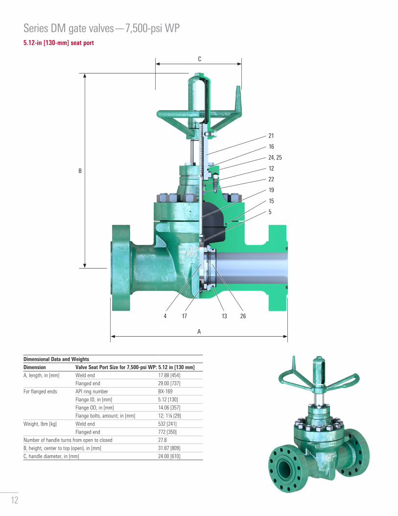
Series DM gate valves—7,500-psi WP5.12-in [130-mm] seat port
Dimensional Data and WeightsDimension Valve Seat Port Size for 7,500-psi WP: 5.12 in [130 mm] A, length, in [mm] Weld end 17.88 [454]
Flanged end 29.00 [737]
For flanged ends API ring number BX-169
Flange ID, in [mm] 5.12 [130]
Flange OD, in [mm] 14.06 [357]
Flange bolts, amount; in [mm] 12; 11/8 [29]
Weight, lbm [kg] Weld end 532 [241]
Flanged end 772 [350]
Number of handle turns from open to closed 27.8
B, height, center to top (open), in [mm] 31.87 [809]
C, handle diameter, in [mm] 24.00 [610]
C
B
A
5
15
12
24, 25
16
21
22
19
4 13 2617
12

Series DM gate valves—7,500-psi WP
Parts ListRepair Kit
Key No.
Qty. Description Valve Seat Port Size for 7,500-psi WP: 5.12 in [130 mm] Repair Kit Component Part NumbersGroup 1 Group 2 Group 3
Assembly Base Number—NACE Compliant J025090 J025109 J0251101 1 Body ASTM A487 Gr. 4 Class D –2 1 Bonnet 4130 –3 4 Capscrew socket head, 5/8 UNC × 1.75 (long) ASTM A574 Alloy Steel 18-8 SS –
■ ● 4 1 Gate 41XX with QPQ nitriding 2171108-01410 SS with QPQ nitriding 2139629-02
■ ● 5 1 Gate clip 3XX SS M4516496 1 Handle ASTM A536 Gr. 65-45-12 –7 1 Handle screw CD 1018/26 –8 12 Heavy hex nut, 11/4-8 UN ASTM A194 Gr. 2H ASTM A194 Gr. 7 –9 4 Hex head bolt, 3/4-10 UNC × 4.00 (long) SAE steel Gr. 5 –10 1 Housing HR 1018/22 –11 1 Lubricating nipple, 1/8 NPT Steel –
■ 12 1 O-ring, AS-568-218, secondary seal HNBR 2712425-12FKM J005531-218
■ 13 2 O-ring, AS-568-435, wear ring seal HNBR 2726268-02FKM J005521-435
■ ● 14 1 O-ring, AS-568-446, bonnet seal HNBR 2712425-78FKM J005521-446
15 1 Retainer HR 1018/22 17-4PH SS –■ 16 1 Rod wiper, housing seal Urethane 2726191-02-95■ ● 17 1 Seat assembly 410 SS with QPQ nitriding and HNBR 2139748-01
410 SS with QPQ nitriding and FKM 2269500-0118 1 Sight tube Clear acrylic –
■ 19 1 Stem 410 SS J024943-10720 1 Stem cap ASTM A536 Gr. 65-45-12 –
■ 21 1 Stem screw CD 1018/26 J023415■ 22 1 Stem seal assembly with bushing HNBR and bronze JN16995-008
FKM and bronze JN16995-00623 12 Stud (double ended), 11/4-8 UN × 6.25 (long) ASTM A193 Gr. B7 ASTM A193 Gr. L7 –
■ 24 2 Thrust needle roller bearing Hardened steel J050911-009■ 25 4 Thrust washer Hardened steel J050911-010■ ● 26 2 Wear ring 41XX with QPQ nitriding M452619
410 SS 2139650-02■ Major repair kit J025177-10574—one each for one year of service.● Minor repair kit J025177-00574.Major and minor repair kits listed for trim option J0XXXXX-XX72140 (410 SS stem, 41XX with QPQ gate, and HNBR seat and seals).Consult Cameron for other repair kit trim options.
J025090-3 7 7 7 1 2 0Assembly Base Number 5�12 in [130 mm], Group 1
Assembly Part Number Example
End ConnectionNo. DescriptionFlanged
3 10,000 RTJ
Weld4 6.00-in [150-mm] XXH
6 7.25-in [184-mm] OD × 5.12-in [130-mm] ID
Seat and Seal ElastomerNo. Description2 FKM and FKM
4 HNBR and HNBR
Ring Groove InlayNo. Description0 –
1 316 SS inlay†
2 625 SS inlay†
† Inlay only available on flanged valves.
Seat Ring MaterialNo. Description1 410 SS
Gate and Wear Ring MaterialNo. Description2 41XX and 41XX
7 410 SS and 410 SS
Stem MaterialNo. Description7 410 SS
Body ConfigurationNo. Description5 Weld
7 Flanged
End connection Stem material
Gate and wear ring material
Seat ring material
Seat and seal elastomerRing groove inlay
13

Series DM gate valves—5,000-psi WP2-in [50-mm] seat port
Dimensional Data and WeightsDimension Valve Seat Port Size for 5,000-psi WP: 2 in [50 mm] A, length, in [mm] Weld and threaded end 9.00 [229]
Flanged end 12.12 [308]
Hammer union end 15.74 [400]
For flanged ends API ring number R-24
Flange ID, in [mm] 2.00 [50]
Flange OD, in [mm] 8.50 [216]
Flange bolts, amount; in [mm] 8; 7/8 [22]
Weight, lbm [kg] Weld and threaded end 58 [26]
Flanged end 103 [47]
Hammer union end 77 [35]
Number of handle turns from open to closed 10.2
B, height, center to top (open), in [mm] 13.00 [330]
C, handle diameter, in [mm] 14.00 [356]
C
B
A
19
11
18
12
13
17
4 15
14

Series DM gate valves—5,000-psi WP
Parts ListRepair Kit
Key No.
Qty. Description Valve Seat Port Size for 5,000-psi WP: 2 in [50 mm] Repair Kit Component Part NumbersAssembly Base Number—NACE Compliant
2-in [50-mm] nominal end—threaded, flanged, weld, and hammer J024929
2.50-in [65-mm] nominal end—weld J0252051 1 Body ASTM A105 for Threaded, weld, and hammer –
ASTM A487 Gr. 4 Class A for Flanged –2 1 Bonnet ASTM A105 –3 1 Coupling ASTM A487 Gr. 4 Class A –
■ ● 4 1 Gate 41XX with electroless nickel plating (ENP) J001887-002ASTM A351 Gr. CF8M J001887-108
5 1 Handle ASTM A536 Gr. 65-45-12 –6 1 Housing CD 1018 –7 1 Index pin Steel –8 1 Lock handle CD 1213/15 –9 1 Lock screw Steel –10 1 Lubricating nipple, 1/8 NPT Steel –
■ 11 1 O-ring, AS-568-210, secondary seal Buna-N J005526-210■ 12 1 O-ring, AS-568-224, housing seal Buna-N J005526-224■ ● 13 1 O-ring, AS-568-342, bonnet seal Buna-N J005526-342
FKM J005531-34214 1 Retainer CD 1213/15 –
■ ● 15 1 Seat assembly 1045 and Buna-N J001876-0111045 and FKM J001876-012
ASTM A351 Gr. CF8M and Buna-N J001876-081ASTM A351 Gr. CF8M and FKM J001876-082
16 1 Split pin, 3/16 × 13/4 Steel –■ 17 1 Stem 316 SS J001931-008■ 18 1 Stem screw CD 1213/15 J001913■ 19 1 Stem seal assembly with bushing Buna-N and bronze JN01949-001
FKM and bronze JN01949-006■ Major repair kit J025216-11221—one each for one year of service.● Minor repair kit J025216-01221.Major and minor repair kits listed for trim option J0XXXXX-XX82110 (316 SS stem, 41XX with ENP gate, and 1045 Buna-N seat and seals).Consult Cameron for other repair kit trim options.
J024929-2 7 8 2 1 1 0Assembly Base Number 2 in [50 mm]
Assembly Part Number Example
End ConnectionNo. DescriptionFlanged
2 5,000 RTJ
Weld1 Sch. 80
2 XXH
5 Sch. 160
Threaded0 LP
2 UPTBG
Hammer union9 2.00-in [50-mm] XXH 1502
hammer union
Seat and Seal ElastomerNo. Description1 Buna-N and
Buna-N
2 FKM and FKM
Ring Groove InlayNo. Description0 –
1 316 SS inlay†
2 625 SS inlay†
† Inlay only available on flanged valves.
Seat Insert MaterialNo. Description1 1045
8 ASTM A351 Gr. CF8M
Gate MaterialNo. Description2 41XX
8 ASTM A351 Gr. CF8M
Stem MaterialNo. Description8 316 SS
Body ConfigurationNo. Description4 Threaded
5 Weld
7 Flanged
9 Hammer union
End connection Stem material
Gate material
Seat insert material
Seat and seal elastomerRing groove inlay
15

Series DM gate valves—5,000-psi WP3-in [80-mm] seat port
Dimensional Data and WeightsDimension Valve Seat Port Size for 5,000-psi WP: 3 in [80 mm] A, length, in [mm] Weld and threaded end 11.00 [279]
Flanged end 15.63 [397]
Hammer union end 4 in 16.88 [429]
3 in 22.62 [574]
For flanged ends API ring number R-35
Flange ID, in [mm] 3.00 [80]
Flange OD, in [mm] 10.50 [267]
Flange bolts, amount; in [mm] 8; 11/8 [29]
Weight, lbm [kg] Weld and threaded end 158 [72]
Flanged end 239 [109]
Hammer union end 4 in 178 [81]
3 in 185 [84]
Number of handle turns from open to closed 11.0
B, height, center to top (open), in [mm] 18.00 [457]
C, handle diameter, in [mm] 19.00 [483]
C
B
A
18
10
17
11
12
16
3 14
16
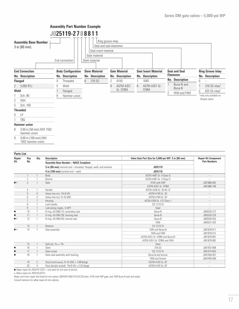
Series DM gate valves—5,000-psi WP
Parts ListRepair Kit
Key No.
Qty. Description Valve Seat Port Size for 5,000-psi WP: 3 in [80 mm] Repair Kit Component Part NumbersAssembly Base Number—NACE Compliant
3-in [80-mm] nominal end—threaded, flanged, weld, and hammer J025119
4-in [100-mm] nominal end—weld J0251161 1 Body ASTM A487 Gr. 4 Class D –2 1 Bonnet ASTM A487 Gr. 4 Class D –
■ ● 3 1 Gate 41XX with ENP J001886-002ASTM A351 Gr. CF8M J001886-108
4 1 Handle ASTM A536 Gr. 65-45-12 –5 4 Heavy hex nut, 13/8-8 UN ASTM A194 Gr. 2H –6 2 Heavy hex nut, 3/4-10 UNC ASTM A194 Gr. 2H –7 1 Housing ASTM A350 Gr. LF2 Class 1 –8 1 Lock handle CD 1213/15 –9 1 Lubricating nipple, 1/8 NPT Steel –
■ 10 1 O-ring, AS-568-212, secondary seal Buna-N J005526-212■ 11 1 O-ring, AS-568-226, housing seal Buna-N J005526-226■ ● 12 1 O-ring, AS-568-433, bonnet seal Buna-N J005526-433
FKM J005531-43313 1 Retainer CD 1213/15 –
■ ● 14 1 Seat assembly 1045 and Buna-N J001878-0111045 and FKM J001878-012
ASTM A351 Gr. CF8M and Buna-N J001878-081ASTM A351 Gr. CF8M and FKM J001878-082
15 1 Split pin, 3/16 × 13/4 Steel –■ 16 1 Stem 316 SS J001932-008■ 17 1 Stem screw CD 1213/15 J001914-003■ 18 1 Stem seal assembly with bushing Buna-N and bronze JN01950-001
FKM and bronze JN01950-00619 2 Stud (continuous), 3/4-10 UNC × 2.88 (long) ASTM A193 Gr. B7 –20 4 Stud (double ended), 13/8-8 UN × 5.25 (long) ASTM A193 Gr. B7 –
■ Major repair kit J025216-12221—one each for one year of service.● Minor repair kit J025216-02221.Major and minor repair kits listed for trim option J0XXXXX-XX82110 (316 SS stem, 41XX with ENP gate, and 1045 Buna-N seat and seals).Consult Cameron for other repair kit trim options.
J025119-2 7 8 8 8 1 1Assembly Base Number 3 in [80 mm]
Assembly Part Number Example
End ConnectionNo. DescriptionFlanged
2 5,000 RTJ
Weld1 Sch. 80
2 XXH
5 Sch. 160
Threaded0 LP
1 TBS
Hammer union8 3.00-in [50-mm] XXH 1502
hammer union
9 4.00-in [100-mm] XXH 1502 hammer union
Seat and Seal ElastomerNo. Description1 Buna-N and
Buna-N
2 FKM and FKM
Ring Groove InlayNo. Description0 –
1 316 SS inlay†
2 625 SS inlay†
† Inlay only available on flanged valves.
Seat Insert MaterialNo. Description1 1045
8 ASTM A351 Gr. CF8M
Gate MaterialNo. Description2 41XX
8 ASTM A351 Gr. CF8M
Stem MaterialNo. Description8 316 SS
Body ConfigurationNo. Description4 Threaded
5 Weld
7 Flanged
9 Hammer union
End connection Stem material
Gate material
Seat insert material
Seat and seal elastomerRing groove inlay
17

Series DM gate valves—5,000-psi WP4-in [100-mm] seat port
Dimensional Data and WeightsDimension Valve Seat Port Size for 5,000-psi WP: 4 in [100 mm] A, length, in [mm] Weld and threaded end 13.00 [330]
Flanged end 18.00 [457]
Hammer union end 5 in 22.62 [574]
4 in 24.62 [625]
For flanged ends API ring number R-39
Flange ID, in [mm] 4.00 [100]
Flange OD, in [mm] 12.25 [311]
Flange bolts, amount; in [mm] 8; 11/4 [32]
Weight, lbm [kg] Weld and threaded end 236 [107]
Flanged end 373 [169]
Hammer union end 5 in 332 [151]
4 in 328 [149]
Number of handle turns from open to closed 22.9
B, height, center to top (open), in [mm] 24.57 [624]
C, handle diameter, in [mm] 23.00 [584]
C
B
A
20
11
23
19
12
9
18
13
4 15
18

Series DM gate valves—5,000-psi WP
Parts ListRepair Kit
Key No.
Qty. Description Valve Seat Port Size for 5,000-psi WP: 4 in [100 mm] Repair Kit Component Part NumbersAssembly Base Number—NACE Compliant
4-in [100-mm] nominal end—threaded, flanged, weld, and hammer J025206
5-in [125-mm] nominal end—weld and hammer J025118
6-in [150-mm] nominal end—weld J0252201 1 Body ASTM A487 Gr. 4 Class D –2 1 Bonnet ASTM A487 Gr. 4 Class D –3 1 Downstop ring 303 SS –
■ ● 4 1 Gate 41XX with ENP J001926-002ASTM A351 Gr. CF8M J001926-108
5 1 Handle ASTM A536 Gr. 65-45-12 –6 4 Heavy hex nut, 13/4 special ASTM A194 Gr. 2H –7 2 Heavy hex nut, 7/9-9 UNC ASTM A194 Gr. 2H –8 1 Housing HR 1018 –
■ 9 1 Key Steel J005305-1001610 1 Lubricating nipple, 1/8 NPT Steel –
■ 11 1 O-ring, AS-568-214, secondary seal Buna-N J005526-214■ 12 1 O-ring, AS-568-226, housing seal Buna-N J005526-226■ ● 13 1 O-ring, AS-568-439, bonnet seal Buna-N J005520-439
FKM J005531-43914 1 Retainer CD 1213/15 –
■ ● 15 1 Seat assembly 1045 and Buna-N J002207-0211045 and FKM J002207-022
ASTM A351 Gr. CF8M and Buna-N J002207-081ASTM A351 Gr. CF8M and FKM J002207-082
16 1 Sight tube Clear acrylic –17 1 Stem cap ASTM A536 Gr. 65-45-12 –
■ 18 1 Stem 316 SS J007439-008■ 19 1 Stem screw CD 1213/15 J007416■ 20 1 Stem seal assembly with bushing Buna-N and bronze JN01951-001
FKM and bronze JN01951-00621 2 Stud (continuous), 7/8-9 UN × 3.50 (long) ASTM A193 Gr. B7 –22 4 Stud (double ended), 13/4 special × 6.00 (long) ASTM A193 Gr. B7 –
■ 23 2 Thrust washer Teflon and phenolic material J007426■ Major repair kit J025216-14221—one each for one year of service.● Minor repair kit J025216-04221.Major and minor repair kits listed for trim option J0XXXXX-XX82110 (316 SS stem, 41XX with ENP gate, and 1045 Buna-N seat and seals).Consult Cameron for other repair kit trim options.
J025206-2 7 8 2 1 2 1Assembly Base Number 4 in [100 mm]
Assembly Part Number Example
End ConnectionNo. DescriptionFlanged
2 5,000 RTJ
Weld1 Sch. 80
2 XXH
5 Sch. 160
Threaded0 LP
1 TBS
Hammer union8 4.00-in [100-mm] XXH
1502 hammer union
9 5.00-in [125-mm] XXH 1502 hammer union
Seat and Seal ElastomerNo. Description1 Buna-N and
Buna-N
2 FKM and FKM
Ring Groove InlayNo. Description0 –
1 316 SS inlay†
2 625 SS inlay†
† Inlay only available on flanged valves.
Seat Insert MaterialNo. Description1 1045
8 ASTM A351 Gr. CF8M
Gate MaterialNo. Description2 41XX
8 ASTM A351 Gr. CF8M
Stem MaterialNo. Description8 316 SS
Body ConfigurationNo. Description4 Threaded
5 Weld
7 Flanged
9 Hammer union
End connection Stem material
Gate material
Seat insert material
Seat and seal elastomerRing groove inlay
19

Series DM gate valves—5,000-psi WP5.12-in [130-mm] seat port
Dimensional Data and WeightsDimension Valve Seat Port Size for 5,000-psi WP: 5.12 in [130 mm] A, length, in [mm] Weld and threaded end 16.00 [406]
Flanged end 28.62 [727]
For flanged ends API ring number R-44
Flange ID, in [mm] 5.12 [130]
Flange OD, in [mm] 14.75 [375]
Flange bolts, amount; in [mm] 8; 11/2 [38]
Weight, lbm [kg] Weld end 329 [149]
Flanged end 611 [277]
Number of handle turns from open to closed 29.6
B, height, center to top (open), in [mm] 30.93 [786]
C, handle diameter, in [mm] 24.00 [610]
C
B
A
22
12
24, 25
13
21
20
14
4 15
20

Series DM gate valves—5,000-psi WP
Parts ListRepair Kit
Key No.
Qty. Description Valve Seat Port Size for 5,000-psi WP: 5.12 in [130 mm] Repair Kit Component Part NumbersAssembly Base Number—NACE Compliant
5-in [125-mm] nominal end—threaded and flanged J025317
6-in [150-mm] nominal end—weld J0253261 1 Body ASTM A487 Gr. 4 Class D –2 1 Bonnet ASTM A487 Gr. 4 Class D –3 1 Downstop ring 303 SS –4 4 Capscrew socket head, 5/8 UNC × 1.75 (long) ASTM A574 Alloy Steel –
■ ● 5 1 Gate 41XX with ENP J021952-002ASTM A487 Gr. CA15 Class C J021952-108
6 1 Handle ASTM A536 Gr. 65-45-12 –7 1 Handle screw CD 1018/26 –8 12 Heavy hex nut, 1-8 UNC ASTM A194 Gr. 2H –9 4 Hex head bolt, 5/8-11 UNC × 3.50 (long) SAE steel Gr. 2 –10 1 Housing HR 1018/22 –11 1 Lubricating nipple, 1/8 NPT Steel –
■ 12 1 O-ring, AS-568-216, secondary seal Buna-N J005526-216■ 13 1 O-ring, AS-568-228, housing seal Buna-N J005526-228■ ● 14 1 O-ring, AS-568-367, bonnet seal Buna-N J005520-367
FKM J005531-36715 1 Relief fitting, 1/8 NPT Steel –16 1 Retainer HR 1018/22 –
■ ● 17 1 Seat assembly 1045 and Buna-N J021948-0191045 and FKM J021948-012
ASTM A487 Gr. CA15 Class C and Buna-N J021948-099ASTM A487 Gr. CA15 Class C and FKM J021948-092
18 1 Sight tube Clear acrylic –19 1 Stem cap ASTM A536 Gr. 65-45-12 –
■ 20 1 Stem 17-4PH SS J021943-009■ 21 1 Stem screw CD 1018/26 J019159■ 22 1 Stem seal assembly with bushing Buna-N and bronze J015853-001
FKM and bronze J015853-00623 12 Stud (double ended), 1-8 UNC × 4.50 (long) ASTM A193 Gr. B7 –
■ 24 2 Thrust needle roller bearing Hardened steel J050911-005■ 25 4 Thrust washer Hardened steel J050911-006■ Major repair kit J025216-15221—one each for one year of service.● Minor repair kit J025216-05221.Major and minor repair kits listed for trim option J0XXXXX-XX82110 (17-4PH SS stem, 41XX with ENP gate, and 1045 Buna-N seat and seals).Consult Cameron for other repair kit trim options.
J025317-7 7 8 8 1 2 0Assembly Base Number
Assembly Part Number Example
End ConnectionNo. DescriptionFlanged
7 5,000 RTJ
Weld2 XXH
5 Sch. 160
Threaded3 LC
Seat and Seal ElastomerNo. Description1 Buna-N and
Buna-N
2 FKM and FKM
Ring Groove InlayNo. Description0 –
1 316 SS inlay†
2 625 SS inlay†
† Inlay only available on flanged valves.
Seat Insert MaterialNo. Description1 1045
8 ASTM A487 Gr. CA15 Class C
Gate MaterialNo. Description2 41XX
8 ASTM A487 Gr. CA15 Class C
Stem MaterialNo. Description8 17-4PH SS
Body ConfigurationNo. Description4 Threaded
5 Weld
7 Flanged
End connection Stem material
Gate material
Seat insert material
Seat and seal elastomerRing groove inlay
21
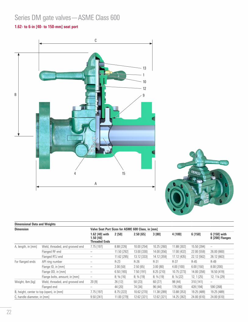
Series DM gate valves—ASME Class 6001.62- to 6-in [40- to 150-mm] seat port
Dimensional Data and WeightsDimension Valve Seat Port Sizes for ASME 600 Class, in [mm]
1.62 [40] with 1.50 [40] Threaded Ends
2 [50] 2.50 [65] 3 [80] 4 [100] 6 [150] 6 [150] with 8 [200] Flanges
A, length, in [mm] Weld, threaded, and grooved end 7.75 [197] 8.88 [226] 10.00 [254] 10.25 [260] 11.88 [302] 15.50 [394] –
Flanged RF end – 11.50 [292] 13.00 [330] 14.00 [356] 17.00 [432] 22.00 [559] 26.00 [660]
Flanged RTJ end – 11.62 [295] 13.12 [333] 14.12 [359] 17.12 [435] 22.12 [562] 26.12 [663]
For flanged ends API ring number – R-23 R-26 R-31 R-37 R-45 R-49
Flange ID, in [mm] – 2.00 [50] 2.50 [65] 3.00 [80] 4.00 [100] 6.00 [150] 8.00 [200]
Flange OD, in [mm] – 6.50 [165] 7.50 [191] 8.25 [210] 10.75 [273] 14.00 [356] 16.50 [419]
Flange bolts, amount; in [mm] – 8; 5/8 [16] 8; 3/4 [19] 8; 3/4 [19] 8; 7/8 [22] 12; 1 [25] 12; 11/8 [29]
Weight, lbm [kg] Weld, threaded, and grooved end 20 [9] 26 [12] 50 [23] 60 [27] 98 [44] 310 [141] –
Flanged end – 44 [20] 74 [34] 96 [44] 176 [80] 428 [194] 590 [268]
B, height, center to top (open), in [mm] 7.75 [197] 8.75 [222] 10.62 [270] 11.38 [289] 13.88 [353] 19.25 [489] 19.25 [489]
C, handle diameter, in [mm] 9.50 [241] 11.00 [279] 12.62 [321] 12.62 [321] 14.25 [362] 24.00 [610] 24.00 [610]
C
B
A
12
9
10
1
13
4 15
22

Series DM gate valves—ASME Class 600
Parts ListKey No.
Qty. Description Valve Seat Port Sizes for ASME 600 Class, in [mm]
1.62 [40] with 1.50 [40] Threaded Ends
2 [50] 2.50 [65] 3 [80] 4 [100] 6 [150] 6 [150] with 8 [200] Flanges
Assembly base number
Threaded J003938 J001072 J001074 J001076 J001078 J001080 –
Weld – J001092 J001094 J001096 J001098 J001100 –
Grooved – J001082 J001084 J001086 J001088 J001090 –
Flanged – J001062 J001064 J001066 J001068 J001070 J003945
1† 1 Backup ring Chrome leather2 1 Body ASTM A216 Gr. WCB3 1 Bonnet ASTM A216 Gr. WCB4† 1 Gate 1045 with ENP
ASTM A351 CF8M5 1 Handle ASTM A536 Gr. 65-45-126 4 Heavy hex nut, body – ASTM A194 Gr. 2H7 4 Hex head bolt, body SAE Gr. 5 Na8 1 Lubricating nipple, 1/8 NPT Steel9† 1 O-ring, bonnet seal Buna-N
FKM10† 1 O-ring, stem seal Buna-N
FKM11† 1 Seat assembly 1045 and Buna-N
1045 and FKMASTM A351 Gr. CF8M and Buna-N
ASTM A351 Gr. CF8M and FKM12† 1 Stem 303 SS
316 SS13† 1 Stem pin Spring steel14 4 Stud (double ended), body – ASTM A193 Gr. B7† Recommended spare parts. Contact Cameron for specific part numbers.
J001072-2 7 2 2 1 1 0Assembly Base Number 2 in [50 mm]
Assembly Part Number Example
End ConnectionNo. DescriptionFlanged
2 600 RTJ
3 600 RF
Weld0 Sch. 40
Threaded0 LP
1 TBG
2 UPTBG
Grooved0 Sch. 80
Seat and Seal ElastomerNo. Description1 Buna-N and
Buna-N
2 FKM and FKM
Ring Groove InlayNo. Description0 –
1 316 SS inlay†
2 625 SS inlay†
† Inlay only available on flanged valves.
Seat Insert MaterialNo. Description1 1045
8 ASTM A351 Gr. CF8M
Gate MaterialNo. Description2 1045
8 ASTM A351 Gr. CF8M
Stem MaterialNo. Description2 303 SS
8 316 SS
Body ConfigurationNo. Description4 Threaded
5 Weld
6 Grooved
7 Flanged
End connection Stem material
Gate material
Seat insert material
Seat and seal elastomerRing groove inlay
23

Series DM gate valves—ASME Class 9002- to 6-in [50- to 150-mm] seat port
Dimensional Data and WeightsDimension Valve Seat Port Sizes for ASME 900 Class, in [mm]
2 [50] 2.50 [65] 3 [80] 4 [100] 6 [150]A, length, in [mm] Weld, threaded, and grooved end 9.00 [229] 9.75 [248] 11.00 [279] 13.00 [330] 20.00 [508]
Flanged RF end 14.50 [368] 16.50 [419] 15.00 [381] 18.00 [457] 24.00 [610]
Flanged RTJ end 14.62 [371] 16.62 [422] 15.12 [384] 18.12 [460] 24.12 [613]
For flanged ends API ring number R-24 R-27 R-31 R-37 R-45
Flange ID, in [mm] 2.00 [50] 2.50 [65] 3.00 [80] 4.00 [100] 6.00 [150]
Flange OD, in [mm] 8.50 [216] 9.62 [244] 9.50 [241] 11.50 [292] 15.00 [381]
Flange bolts, amount; in [mm] 8; 7/8 [22] 8; 1 [25] 8; 7/8 [22] 8; 11/8 [19] 12; 11/8 [19]
Weight, lbm [kg] Weld, threaded, and grooved end 48 [22] 87 [39] 95 [43] 140 [64] 325 [147]
Flanged end 100 [45] 170 [77] 160 [73] 230 [104] 540 [245]
B, height, center to top (open), in [mm] 9.88 [251] 22.88 [581] 12.75 [324] 15.00 [381] 19.25 [489]
C, handle diameter, in [mm] 14.50 [368] 19.00 [483] 19.00 [483] 23.00 [584] 24.00 [610]
C
B
A
9
13
8
10
1
14
4 12
24
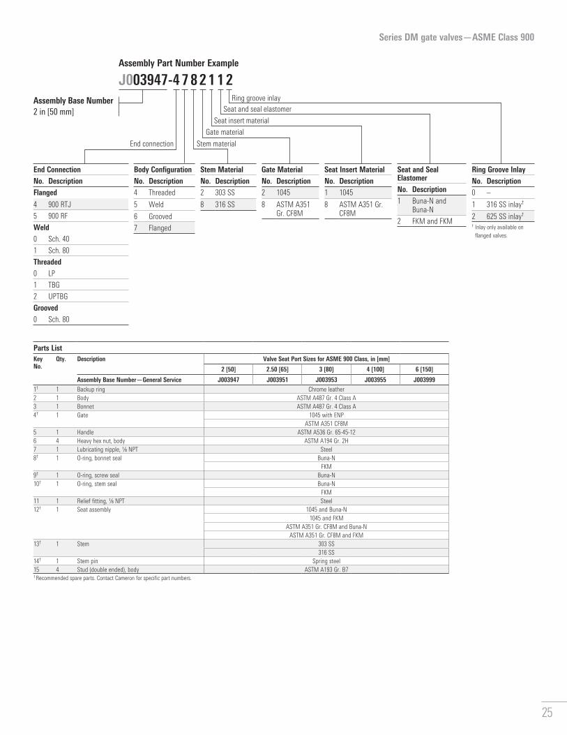
Series DM gate valves—ASME Class 900
Parts ListKey No.
Qty. Description Valve Seat Port Sizes for ASME 900 Class, in [mm]
2 [50] 2.50 [65] 3 [80] 4 [100] 6 [150]
Assembly Base Number—General Service J003947 J003951 J003953 J003955 J0039991† 1 Backup ring Chrome leather2 1 Body ASTM A487 Gr. 4 Class A3 1 Bonnet ASTM A487 Gr. 4 Class A4† 1 Gate 1045 with ENP
ASTM A351 CF8M5 1 Handle ASTM A536 Gr. 65-45-126 4 Heavy hex nut, body ASTM A194 Gr. 2H7 1 Lubricating nipple, 1/8 NPT Steel8† 1 O-ring, bonnet seal Buna-N
FKM9† 1 O-ring, screw seal Buna-N10† 1 O-ring, stem seal Buna-N
FKM11 1 Relief fitting, 1/8 NPT Steel12† 1 Seat assembly 1045 and Buna-N
1045 and FKMASTM A351 Gr. CF8M and Buna-N
ASTM A351 Gr. CF8M and FKM13† 1 Stem 303 SS
316 SS14† 1 Stem pin Spring steel15 4 Stud (double ended), body ASTM A193 Gr. B7† Recommended spare parts. Contact Cameron for specific part numbers.
J003947-4 7 8 2 1 1 2Assembly Base Number 2 in [50 mm]
Assembly Part Number Example
End ConnectionNo. DescriptionFlanged
4 900 RTJ
5 900 RF
Weld0 Sch. 40
1 Sch. 80
Threaded0 LP
1 TBG
2 UPTBG
Grooved0 Sch. 80
Seat and Seal ElastomerNo. Description1 Buna-N and
Buna-N
2 FKM and FKM
Ring Groove InlayNo. Description0 –
1 316 SS inlay†
2 625 SS inlay†
† Inlay only available on flanged valves.
Seat Insert MaterialNo. Description1 1045
8 ASTM A351 Gr. CF8M
Gate MaterialNo. Description2 1045
8 ASTM A351 Gr. CF8M
Stem MaterialNo. Description2 303 SS
8 316 SS
Body ConfigurationNo. Description4 Threaded
5 Weld
6 Grooved
7 Flanged
End connection Stem material
Gate material
Seat insert material
Seat and seal elastomerRing groove inlay
25

Series DM gate valves—ASME Class 15002- to 3-in [50- to 80-mm] seat port
Dimensional Data and WeightsDimension Valve Seat Port Sizes for ASME 1500 Class, in [mm]
2 [50] 2.50 [65] 3 [80]A, length, in [mm] Weld, threaded, and grooved end 9.00 [229] 9.75 [248] 11.00 [279]
Flanged RF end 14.50 [368] 16.50 [419] 18.50 [470]
Flanged RTJ end 14.62 [371] 16.62 [422] 18.62 [473]
For flanged ends API ring number R-24 R-27 R-35
Flange ID, in [mm] 2.00 [50] 2.50 [65] 3.00 [80]
Flange OD, in [mm] 8.50 [216] 9.62 [244] 10.50 [267]
Flange bolts, amount; in [mm] 8; 7/8 [22] 8; 1 [25] 8; 11/8 [29]
Weight, lbm [kg] Weld, threaded, and grooved end 48 [22] 87 [39] 113 [51]
Flanged end 100 [45] 170 [77] 205 [93]
B, height, center to top (open), in [mm] 9.88 [25] 22.88 [581] 12.75 [324]
C, handle diameter, in [mm] 14.50 [368] 19.00 [483] 19.00 [483]
C
B
A
4 12
9
13
8
10
1
14
26

Series DM gate valves—ASME Class 1500
Parts ListKey No.
Qty. Description Valve Seat Port Sizes for ASME 1500 Class, in [mm]
2 [50] 2.50 [65] 3 [80]
Assembly Base Number—General Service J003948 J003952 J0039571† 1 Backup ring Chrome leather2 1 Body ASTM A487 Gr. 4 Class A3 1 Bonnet ASTM A487 Gr. 4 Class A4† 1 Gate 1045 with ENP
ASTM A351 CF8M5 1 Handle ASTM A536 Gr. 65-45-126 4 Heavy hex nut, body ASTM A194 Gr. 2H7 1 Lubricating nipple, 1/8 NPT Steel8† 1 O-ring, bonnet seal Buna-N
FKM9† 1 O-ring, screw seal Buna-N10† 1 O-ring, stem seal Buna-N
FKM11 1 Relief fitting, 1/8 NPT Steel12† 1 Seat assembly 1045 and Buna-N
1045 and FKMASTM A351 Gr. CF8M and Buna-N
ASTM A351 Gr. CF8M and FKM13† 1 Stem 303 SS
316 SS14† 1 Stem pin Spring steel15 4 Stud (double ended), body ASTM A193 Gr. B7† Recommended spare parts. Contact Cameron for specific part numbers.
J003948-6 7 2 8 8 1 1Assembly Base Number 2 in [50 mm], flanged
Assembly Part Number Example
End ConnectionNo. DescriptionFlanged
6 1500 RTJ
7 1500 RF
Weld0 Sch. 40
1 Sch. 80
5 Sch. 160
Threaded0 LP
1 TBG
2 UPTBG
Grooved0 Sch. 80
Seat and Seal ElastomerNo. Description1 Buna-N and
Buna-N
2 FKM and FKM
Ring Groove InlayNo. Description0 –
1 316 SS inlay†
2 625 SS inlay†
† Inlay only available on flanged valves.
Seat Insert MaterialNo. Description1 1045
8 ASTM A351 Gr. CF8M
Gate MaterialNo. Description2 1045
8 ASTM A351 Gr. CF8M
Stem MaterialNo. Description2 303 SS
8 316 SS
Body ConfigurationNo. Description4 Threaded
5 Weld
6 Grooved
7 Flanged
End connection Stem material
Gate material
Seat insert material
Seat and seal elastomerRing groove inlay
27

Series DM gate valves—ASME Class 15004-in [100-mm] seat port
Dimensional Data and WeightsDimension Valve Seat Port Size for ASME 1500 Class: 4 in [100 mm] A, length, in [mm] Weld, and threaded end 13.00 [330]
Flanged RF end 21.50 [546]
Flanged RTJ end 21.62 [549]
For flanged ends API ring number R-39
Flange ID, in [mm] 4.00 [100]
Flange OD, in [mm] 12.25 [311]
Flange bolts, amount; in [mm] 8; 11/4 [32]
Weight, lbm [kg] Weld, and threaded end 162 [73]
Flanged end 320 [145]
B, height, center to top (open), in [mm] 21.25 [540]
C, handle diameter, in [mm] 23.00 [854]
C
B
A
18
16
10
12
17
11
3 14
28

Series DM gate valves—ASME Class 1500
Parts ListKey No.
Qty. Description Valve Seat Port Size for ASME 1500 Class: 4 in [100 mm]
Assembly Base Number—General Service J0030101 1 Body ASTM A487 Gr. 4 Class A2 1 Bonnet ASTM A487 Gr. 4 Class A3† 1 Gate 41XX with ENP
ASTM A351 Gr. CF8M4 1 Handle ASTM A536 Gr. 65-45-125 4 Heavy hex nut, body ASTM A194 Gr. 2H6 2 Heavy hex nut, bonnet ASTM A194 Gr. 2H7 1 Housing CD 10298 1 Lock handle CD 1213/159 1 Lubricating nipple, 1/8 NPT Steel10† 1 O-ring, bonnet seal Buna-N
FKM11† 1 O-ring, housing seal Buna-N12† 1 O-ring, secondary seal Buna-N13 1 Retainer CD 1213/1514† 1 Seat assembly 1045 and Buna-N
1045 and FKMASTM A351 Gr. CF8M and Buna-N
ASTM A351 Gr. CF8M and FKM15 1 Split pin, 3/16 in × 13/4 in Steel16† 1 Stem 303 SS
316 SS17† 1 Stem screw CD 1213/1518† 1 Stem seal assembly with bushing Buna-N and bronze
FKM and bronze19 2 Stud (continuous), bonnet ASTM A193 Gr. B720 4 Stud (double ended), body ASTM A193 Gr. B7† Recommended spare parts. Contact Cameron for specific part numbers.
J003948-6 7 2 2 1 2 2Assembly Base Number 4 in [100 mm]
Assembly Part Number Example
End ConnectionNo. DescriptionFlanged
6 1500 RTJ
7 1500 RF
Weld0 Sch. 40
1 Sch. 80
5 Sch. 160
Threaded0 LP
3 LCSG
Seat and Seal ElastomerNo. Description1 Buna-N and
Buna-N
2 FKM and FKM
Ring Groove InlayNo. Description0 –
1 316 SS inlay†
2 625 SS inlay†
† Inlay only available on flanged valves.
Seat Insert MaterialNo. Description1 1045
8 ASTM A351 Gr. CF8M
Gate MaterialNo. Description2 41XX
8 ASTM A351 Gr. CF8M
Stem MaterialNo. Description2 303 SS
8 316 SS
Body ConfigurationNo. Description4 Threaded
5 Weld
7 Flanged
End connection Stem material
Gate material
Seat insert material
Seat and seal elastomerRing groove inlay
29

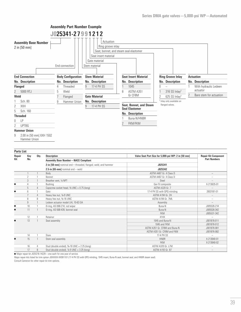
Series DMA gate valves—7,500-psi WP—Automated2-in [50-mm] seat port
Dimensional Data and WeightsDimension Valve Seat Port Size for for 7,500-psi WP: 2 in [50 mm]A, length, in [mm] Weld end 9.00 [229]
Flanged end 20.50 [521]
Hammer union end 15.74 [400]
For flanged ends API ring number BX-152
Flange ID, in [mm] 2.00 [50]
Flange OD, in [mm] 7.88 [200]
Flange bolts, amount; in [mm] 8; 3/4 [19]
Weight, with actuator, lbm [kg] Weld end 108 [49]
Flanged end 169 [77]
Hammer union end 126 [57]
Cylinder max pressure, psi [MPa] 3,000 [20.7]
Cylinder inlet/outlet connection 4X 3/8 NPT
B, height, center to top, in [mm] 19.95 [507]
B
A
7
17
3
11
13
6 12 2015
30

Series DMA gate valves—7,500-psi WP—Automated
J025296-3 7 8 9 1 2 0 1Assembly Base Number 2 in [50 mm]
Assembly Part Number Example
End ConnectionNo. DescriptionFlanged
3 10000 RTJ
Weld2 2.00 in [50 mm] XXH
4 3.00 in [80 mm] OD × 2.00 in [50mm] ID
Hammer Union8 2.00 in [50 mm] XXH 1502
hammer union
Seat and Seal ElastomerNo. Description2 FKM
4 HNBR
ActuationNo. Description1 With hydraulic Ledeen*
actuator
2 Bare stem for actuation
Ring Groove InlayNo. Description0 –
1 316 SS Inlay†
2 625 SS Inlay†
† Inlay only available on flanged valves.
Seat Ring MaterialNo. Description1 410 SS
Gate/Wear Ring MaterialNo. Description8 17-4 PH SS/410 SS
9 17-4 PH SS/41XX
Stem MaterialNo. Description8 17-4 PH SS
Body ConfigurationNo. Description5 Weld
7 Flanged
9 Hammer union
End connection Stem material
Gate/wear ring material
Seat ring material
Seat and seal elastomerRing groove inlay
Actuation
Parts ListRepair Kit
Key No.
Qty. Description Valve Seat Port Size for 7,500-psi WP: 3 in [80 mm] Repair Kit Component Part NumbersGroup 1 Group 2 Group 3
Assembly Base Number—NACE Compliant J025296 J025343 J0253441 1 Body ASTM A487 Gr. 4 Class D –2 1 Bonnet 4130 –
■ 3 1 Bushing Gar-Fil composite –4 1 Breather vent, 1/8 NPT Steel X-213635-015 4 Capscrew socket head, 3/8 UNC × 0.75 (long) ASTM A320 Gr. L7M –
■ 6 1 Gate 17-4 PH SS with QPQ nitriding 2603688-01■ 7 1 Gate clip 3XX SS M450480
8 12 Heavy hex nut, 1-8 UNC ASTM A194 Gr. 2H ASTM A194 Gr. 7 –9 8 Heavy hex nut, 3/8-16 UNC ASTM A194 Gr. 7 –10 1 Ledeen actuator model LHL 70-60 DA Assembly –
■ 11 1 O-ring, AS-568-224, rod wiper Buna-N J005526-214■ 12 2 O-ring, AS-568-229, wear ring seal HNBR 2712425-03
FKM J005521-229■ 13 1 O-ring, AS-568-342, bonnet seal HNBR 2712425-60
FKM J005521-34214 1 Retainer 41XX –
■ 15 1 Seat assembly 410 SS with QPQ nitriding and HNBR 2139742-01410 SS with QPQ nitriding and FKM 2139741-02
16 1 Stem 17-4 PH SS with ENP –■ 17 1 Stem seal assembly HNBR X-213640-01
FKM X-213640-0218 12 Stud (double ended), 1-8 UNC × 4.00 (long) ASTM A193 Gr. B7 ASTM A193 Gr. L7 –19 8 Stud (double ended), 3/8-16 UNC × 2.25 (long) ASTM A320 Gr. L7 –
■ 20 2 Wear ring 41XX with QPQ nitriding M452267410 SS 2139647-02
■ Major repair kit J025177-10279—one each for one year of service.Major repair kits listed for trim option J0XXXXX-XX891401 (17-4 PH SS stem, 17-4 PH SS with QPQ gate, HNBR seat and seals).Consult Cameron for other repair kit trim options.
31

Series DMA gate valves—7,500-psi WP—Automated3-in [80-mm] seat port
Dimensional Data and WeightsDimension Valve Seat Port Size for for 7,500-psi WP: 3 in [80 mm]A, length, in [mm] Weld end 13.00 [330]
Flanged end 24.38 [619]
Hammer union end 4 in 24.62 [625]
3 in 18.88 [480]
For flanged ends API ring number BX-154
Flange ID, in [mm] 3.00 [80]
Flange OD, in [mm] 10.62 [270]
Flange bolts, amount; in [mm] 8; 1 [25]
Weight, with actuator, lbm [kg] Weld end 215 [97]
Flanged end 328 [149]
Hammer union end 4 in 299 [135]
3 in 241 [109]
Cylinder max pressure, psi [MPa] 3,000 [20.7]
Cylinder inlet/outlet connection 4X 3/8 NPT
B, height, center to top, in [mm] 22.26 [565]
B
A
13
17
4
11
7
6 12 2015
32

Series DMA gate valves—7,500-psi WP—Automated
J025295-3 7 8 8 1 4 2 1Assembly Base Number 3 in [80 mm]
Assembly Part Number Example
End ConnectionNo. DescriptionFlanged
3 10000 RTJ
Weld2 3.00 in [80 mm] XXH
4 4.00 in [100 mm] XXH
5 4.50 in [114 mm] OD × 2.96 in [75 mm] ID
Hammer Union8 3.00 in [80 mm] XXH 1502
hammer union
9 4.00 in [100 mm] XXH 1502 hammer union
Seat and Seal ElastomerNo. Description2 FKM
4 HNBR
ActuationNo. Description1 With hydraulic Ledeen
actuator
2 Bare stem for actuation
Ring Groove InlayNo. Description0 –
1 316 SS Inlay†
2 625 SS Inlay†
† Inlay only available on flanged valves.
Seat Ring MaterialNo. Description1 410 SS
Gate/Wear Ring MaterialNo. Description8 17-4 PH SS/410 SS
9 17-4 PH SS/41XX
Stem MaterialNo. Description8 17-4 PH SS
Body ConfigurationNo. Description5 Weld
7 Flanged
9 Hammer union
End connection Stem material
Gate/wear ring material
Seat ring material
Seat and seal elastomerRing groove inlay
Actuation
Parts ListRepair Kit
Key No.
Qty. Description Valve Seat Port Size for 7,500-psi WP: 2 in [50 mm] Repair Kit Component Part NumbersGroup 1 Group 2 Group 3
Assembly Base Number—NACE Compliant J025295 J025331 J0253321 1 Body ASTM A487 Gr. 4 Class D –2 1 Bonnet 4130 –3 1 Breather vent, 1/8 NPT Steel –
■ 4 1 Bushing Gar-Fil composite X-213633-015 4 Capscrew socket head, 3/8 UNC × 0.75 (long) ASTM A320 Gr. L7M –
■ 6 1 Gate 17-4 PH SS with QPQ nitriding X-213643-01■ 7 1 Gate clip 3XX SS X-213652-01
8 12 Heavy hex nut, 1-8 UNC ASTM A194 Gr. 2H ASTM A194 Gr. 7 –9 8 Heavy hex nut, 3/8-16 UNC ASTM A194 Gr. 7 –10 1 Ledeen actuator model LHL 85-84 DA Assembly –
■ 11 1 O-ring, AS-568-217, rod wiper Buna-N J005526-217■ 12 2 O-ring, AS-568-340, wear ring seal HNBR 2712783-03
FKM J005521-340■ 13 1 O-ring, AS-568-361, bonnet seal HNBR 2712787-07
FKM J005521-36114 1 Retainer 41XX –
■ 15 1 Seat assembly 410 SS with QPQ nitriding and HNBR 2139744-01410 SS with QPQ nitriding and FKM 2139743-02
16 1 Stem 17-4 PH SS –■ 17 1 Stem seal assembly HNBR X-213638-01
FKM X-213638-0218 12 Stud (double ended), 1-8 UNC × 4.50 (long) ASTM A193 Gr. B7 ASTM A320 Gr. L7 –19 8 Stud (double ended), 3/8-16 UNC × 2.25 (long) ASTM A320 Gr. L7 –
■ 20 2 Wear ring 41XX with QPQ nitriding M452571410 SS 2139648-02
■ Major repair kit J025177-10379—one each for one year of service.Major repair kits listed for trim option J0XXXXX-XX891401 (17-4 PH SS stem, 17-4 PH SS with QPQ gate, HNBR seat and seals).Consult Cameron for other repair kit trim options.
33

Dimensional Data and WeightsDimension Valve Seat Port Size for for 7,500-psi WP: 4 in [100 mm]A, length, in [mm] Weld end 16.00 [406]
Flanged end 26.38 [670]
Hammer union end 5 in 25.62 [651]
4 in 27.62 [702]
For flanged ends API ring number BX-155
Flange ID, in [mm] 4.00 [100]
Flange OD, in [mm] 12.44 [316]
Flange bolts, amount; in [mm] 8; 11/8 [29]
Weight, with actuator, lbm [kg] Weld end 311 [140]
Flanged end 486 [220]
Hammer union end 5 in 409 [185]
4 in 395 [179]
Cylinder max pressure, psi [MPa] 3,000 [20.7]
Cylinder inlet/outlet connection 4X 1/2 NPT
B, height, center to top, in [mm] 25.47 [647]
Series DMA gate valves—7,500-psi WP—Automated4-in [100-mm] seat port
B
A
13
17
4
11
7
6 12 2015
34

Series DMA gate valves—7,500-psi WP—Automated
J025294-3 7 8 8 1 2 1 2Assembly Base Number 4 in [100 mm]
Assembly Part Number Example
End ConnectionNo. DescriptionFlanged
3 10000 RTJ
Weld2 4.00 in [100 mm] XXH
3 5.00 in [125 mm] XXH
4 5.81 in [148 mm] OD × 4.06 in [103 mm]
5 6.00 in [152 mm] OD × 4.00 in [100 mm] ID
Threaded8 4.00 in [100 mm] XXH 1502
Hammer Union
9 5.00 in [125 mm] XXH 1502 Hammer Union
Body ConfigurationNo. Description5 Weld
7 Flanged
9 Hammer Union
End connection Stem material
Gate/wear ring material
Seat ring material
Seat and seal elastomerRing groove inlay
Parts ListRepair Kit
Key No.
Qty. Description Valve Seat Port Size for 7,500-psi WP: 4 in [100 mm] Repair Kit Component Part NumbersGroup 1 Group 2 Group 3
Assembly Base Number—NACE Compliant J025294 J025329 J0253301 1 Body ASTM A487 Gr. 4 Class D –2 1 Bonnet 4130 –3 1 Breather vent, 1/8 NPT Steel –
■ 4 1 Bushing Gar-Fil composite X-213632-015 4 Capscrew socket head, 7/16 UNC × 0.88 (long) ASTM A320 Gr. L7M –
■ 6 1 Gate 17-4 PH SS with QPQ nitriding X-213642-01■ 7 1 Gate clip 3XX SS X-213651-01
8 10 Heavy hex nut, 11/8-8 UNC ASTM A194 Gr. 2H ASTM A194 Gr. 7 –9 8 Heavy hex nut, 7/16-14 UNC ASTM A194 Gr. 7 –10 1 Ledeen actuator model LHL 100-110 DA Assembly –
■ 11 1 O-ring, AS-568-220, rod wiper Buna-N J005526-220■ 12 2 O-ring, AS-568-349, wear ring seal HNBR 2712787-04
FKM J005521-349■ 13 1 O-ring, AS-568-364, bonnet seal HNBR 2712426-11
FKM J005521-36414 1 Retainer 41XX –
■ 15 1 Seat assembly 410 SS with QPQ nitriding and HNBR 2139746-01410 SS with QPQ nitriding and FKM 2139745-02
16 1 Stem 17-4 PH SS –■ 17 1 Stem seal assembly HNBR X-213637-01
FKM X-213637-0218 10 Stud (double ended), 11/8-8 UNC × 5.50 (long) ASTM A193 Gr. B7 ASTM A320 Gr. L7 –19 8 Stud (double ended), 7/16-14 UNC × 2.63 (long) ASTM A320 Gr. L7 –
■ 20 2 Wear ring 41XX with QPQ nitriding M452290410 SS 2139649-02
■ Major repair kit J025177-10479—one each for one year of service.Major repair kits listed for trim option J0XXXXX-XX891401 (17-4 PH SS stem, 17-4 PH with QPQ gate, HNBR seat and seals).Consult Cameron for other repair kit trim options.
Seat and Seal ElastomerNo. Description2 FKM
4 HNBR
ActuationNo. Description1 With hydraulic Ledeen
actuator
2 Bare stem for actuation
Ring Groove InlayNo. Description0 –
1 316 SS Inlay†
2 625 SS Inlay†
† Inlay only available on flanged valves.
Seat Ring MaterialNo. Description1 410 SS
Gate/Wear Ring MaterialNo. Description8 17-4 PH SS/410 SS
9 17-4 PH SS/41XX
Stem MaterialNo. Description8 17-4 PH SS
Actuation
35

Series DMA gate valves—7,500-psi WP—Automated5.12-in [130-mm] seat port
Dimensional Data and WeightsDimension Valve Seat Port Size for for 7,500-psi WP: 5.12 in [130 mm]A, length, in [mm] Weld end 17.88 [454]
Flanged end 29.00 [737]
For flanged ends API ring number BX-169
Flange ID, in [mm] 5.12 [130]
Flange OD, in [mm] 14.06 [357]
Flange bolts, amount; in [mm] 12; 11/8 [29]
Weight, with actuator, lbm [kg] Weld end 600 [272]
Flanged end 839 [381]
Cylinder max pressure, psi [MPa] 3,000 [20.7]
Cylinder inlet/outlet connection 4X 1/2 NPT
B, height, center to top, in [mm] 30.66 [779]
B
A
13
17
4
11
7
6 12 2015
36

Series DMA gate valves—7,500-psi WP—Automated
J025293-3 7 8 9 1 2 1 1Assembly Base Number 5�12 in [130 mm]
Assembly Part Number Example
Parts ListRepair Kit
Key No.
Qty. Description Valve Seat Port Size for 7,500-psi WP: 5.12 in [130 mm] Repair Kit Component Part NumbersGroup 1 Group 2 Group 3
Assembly Base Number—NACE Compliant J025293 J025327 J0253281 1 Body ASTM A487 Gr. 4 Class D –2 1 Bonnet 4130 –3 1 Breather vent, 1/8 NPT Steel –
■ 4 1 Bushing Gar-Fil composite X-213631-015 4 Capscrew socket head, 5/8 UNC × 1.00 (long) ASTM A320 Gr. L7M –
■ 6 1 Gate 17-4 PH SS with QPQ nitriding X-213641-01■ 7 1 Gate clip 3XX SS X-213650-01
8 12 Heavy hex nut, 11/4-8 UNC ASTM A194 Gr. 2H ASTM A194 Gr. 7 –9 8 Heavy hex nut, 5/8-11 UNC ASTM A194 Gr. 7ML –10 1 Ledeen actuator model LHL 120-143 DA Assembly –
■ 11 1 O-ring, AS-568-224, rod wiper Buna-N J005526-224■ 12 2 O-ring, AS-568-435, wear ring seal HNBR 2726268-02
FKM J005521-435■ 13 1 O-ring, AS-568-446, bonnet seal HNBR 2712425-78
FKM J005521-44614 1 Retainer 41XX –
■ 15 1 Seat assembly 410 SS with QPQ nitriding and HNBR 2139748-01410 SS with QPQ nitriding and FKM 2269500-01
16 1 Stem 17-4 PH SS –■ 17 1 Stem seal assembly HNBR X-213636-01
FKM X-213636-0218 12 Stud (double ended), 11/4-8 UNC × 6.25 (long) ASTM A193 Gr. B7 ASTM A320 Gr. L7 –19 8 Stud (double ended), 5/8-11 UNC × 3.25 (long) ASTM A320 Gr. L7M –
■ 20 2 Wear ring 41XX with QPQ nitriding M452619410 SS 2139650-02
■ Major repair kit J025177-10579—one each for one year of service.Major repair kits listed for trim option J0XXXXX-XX891401 (17-4 PH SS stem, 17-4 PH with QPQ gate, HNBR seat and seals).Consult Cameron for other repair kit trim options.
End ConnectionNo. DescriptionFlanged
3 10000 RTJ
Weld4 6.00 in [150 mm] XXH
6 7.25 in [184 mm] OD × 5.12 in [130 mm] ID
Body ConfigurationNo. Description5 Weld
7 Flanged
9 Hammer Union
End connection Stem material
Gate/wear ring material
Seat ring material
Seat and seal elastomerRing groove inlay
Seat and Seal ElastomerNo. Description2 FKM/FKM
4 HNBR/HNBR
ActuationNo. Description1 With hydraulic Ledeen
actuator
2 Bare stem for actuation
Ring Groove InlayNo. Description0 –
1 316 SS Inlay†
2 625 SS Inlay†
† Inlay only available on flanged valves.
Seat Ring MaterialNo. Description1 410 SS
Gate/Wear Ring MaterialNo. Description8 17-4 PH SS/410 SS
9 17-4PH SS/41XX
Stem MaterialNo. Description8 17-4 PH SS
Actuation
37

Series DMA gate valves—5,000-psi WP—Automated2-in [50-mm] seat port
Dimensional Data and WeightsDimension Valve Seat Port Size for for 5,000-psi WP: 2 in [50 mm]A, length, in [mm] Weld end 9.00 [229]
Flanged end 12.12 [308]
Hammer union end 15.74 [400]
For flanged ends API ring number R-24
Flange ID, in [mm] 2.00 [50]
Flange OD, in [mm] 8.50 [216]
Flange bolts, amount; in [mm] 8; 7/8 [22]
Weight, with actuator, lbm [kg] Weld, and threaded end 86 [39]
Flanged end 131 [60]
Hammer union end 105 [48]
Cylinder max pressure, psi [MPa] 3,000 [20.7]
Cylinder inlet/outlet connection 4X 3/8 NPT
B, height, center to top, in [mm] 19.56 [497]
B
A
11
15
4
10
6 13
38
Series DMA gate valves—5,000-psi WP—Automated
J025341-2 7 9 9 1 2 1 2Assembly Base Number 2 in [50 mm]
Assembly Part Number Example
Parts ListRepair Kit
Key No.
Qty. Description Valve Seat Port Size for 5,000-psi WP: 2 in [50 mm] Repair Kit Component Part NumbersAssembly Base Number—NACE Compliant
2-in [50-mm] nominal end—threaded, flanged, weld, and hammer J025341
2.5-in [65-mm] nominal end—weld J0253421 1 Body ASTM A487 Gr. 4 Class D –2 1 Bonnet ASTM A487 Gr. 4 Class D –3 1 Breather vent, 1/8 NPT Steel –
■ 4 1 Bushing Gar-Fil composite X-213635-015 4 Capscrew socket head, 3/8 UNC × 0.75 (long) ASTM A320 Gr. 7 –
■ 6 1 Gate 17-4 PH SS with QPQ nitriding 2603181-017 4 Heavy hex nut, 7/8-9 UNC ASTM A194 Gr. 2H –8 8 Heavy hex nut, 3/8-16 UNC ASTM A194 Gr. 7ML –9 1 Ledeen actuator model LHL 70-63 DA Assembly –
■ 10 1 O-ring, AS-568-214, rod wiper Buna-N J005526-214■ 11 1 O-ring, AS-568-439, bonnet seal Buna-N J005526-342
FKM J005531-34212 1 Retainer 41XX –
■ 13 1 Seat assembly 1045 and Buna-N J001876-0111045 and FKM J001876-012
ASTM A351 Gr. CF8M and Buna-N J001876-081ASTM A351 Gr. CF8M and FKM J001876-082
14 1 Stem 17-4 PH SS –■ 15 1 Stem seal assembly HNBR X-213640-01
FKM X-213640-0216 4 Stud (double ended), 3/8-16 UNC × 2.25 (long) ASTM A320 Gr. L7M –17 8 Stud (double ended), 7/8-9 UNC × 3.25 (long) ASTM A193 Gr. B7 –
■ Major repair kit J025216-14229—one each for one year of service.Major repair kits listed for trim option J0XXXXX-XX991101 (17-4 PH SS with QPQ nitriding, 1045 insert, Buna-N seat, bonnet seal, and HNBR steam seal).Consult Cameron for other repair kit trim options.
End ConnectionNo. DescriptionFlanged
2 5000 RTJ
Weld1 Sch. 80
2 XXH
5 Sch. 160
Threaded0 LP
2 UPTBG
Hammer Union9 2.00 in [50 mm] XXH 1502
Hammer Union
Body ConfigurationNo. Description4 Threaded
5 Weld
7 Flanged
9 Hammer Union
End connection Stem material
Gate material
Seat insert material
Seat, bonnet, and steam seal elastomerRing groove inlay
Seat, Bonnet, and Steam Seal ElastomerNo. Description1 Buna-N/HNBR
2 FKM/FKM
ActuationNo. Description1 With hydraulic Ledeen
actuator
2 Bare stem for actuation
Ring Groove InlayNo. Description0 –
1 316 SS Inlay†
2 625 SS Inlay†
† Inlay only available on flanged valves.
Seat Insert MaterialNo. Description1 1045
8 ASTM A351 Gr CF8MGate Material
No. Description9 17-4 PH SS
Stem MaterialNo. Description9 17-4 PH SS
Actuation
39

Series DMA gate valves—5,000-psi WP—Automated4-in [100-mm] seat port
Dimensional Data and WeightsDimension Valve Seat Port Size for for 5,000-psi WP: 4 in [100 mm]A, length, in [mm] Weld end 13.00 [330]
Flanged end 18.00 [457]
Hammer union end 5 in 22.62 [574]
4 in 24.62 [625]
For flanged ends API ring number R-39
Flange ID, in [mm] 4.00 [100]
Flange OD, in [mm] 12.25 [311]
Flange bolts, amount; in [mm] 8; 11/4 [32]
Weight, with actuator, lbm [kg] Weld, and threaded end 272 [123]
Flanged end 409 [185]
Hammer union end 5 in 368 [167]
4 in 364 [165]
Cylinder max pressure, psi [MPa] 3,000 [20.7]
Cylinder inlet/outlet connection 4X 1/2 NPT
B, height, center to top, in [mm] 27.11 [689]
B
A
11
15
4
10
6 13
40

Series DMA gate valves—5,000-psi WP—Automated
J025297-2 7 9 9 8 1 0 1Assembly Base Number 4 in [100 mm]
Assembly Part Number Example
Parts ListRepair Kit
Key No.
Qty. Description Valve Seat Port Size for 5,000-psi WP: 4 in [100 mm] Repair Kit Component Part NumbersAssembly Base Number—NACE Compliant
4-in [100-mm] nominal end—threaded, flanged, weld, and hammer J025297
5-in [125-mm] nominal end—weld and hammer J0253331 1 Body ASTM A487 Gr. 4 Class D –2 1 Bonnet ASTM A487 Gr. 4 Class D –3 1 Breather vent, 1/8 NPT Steel –
■ 4 1 Bushing Gar-Fil composite X-213632-015 4 Capscrew socket head, 7/16 UNC × 0.88 (long) ASTM A320 Gr. 7 –
■ 6 1 Gate 17-4 PH SS with QPQ nitriding 2603247-017 4 Heavy hex nut, 13/4 special ASTM A194 Gr. 2H –8 8 Heavy hex nut, 7/16-14 UNC ASTM A194 Gr. 7ML –9 1 Ledeen actuator model LHL 100-119 DA Assembly –
■ 10 1 O-ring, AS-568-220, rod wiper Buna-N J005526-220■ 11 1 O-ring, AS-568-439, bonnet seal Buna-N J005526-439
FKM J005531-43912 1 Retainer 41XX –
■ 13 1 Seat assembly 1045 and Buna-N X-213637-011045 and FKM X-213637-02
ASTM A351 Gr. CF8M and Buna-N J002207-081ASTM A351 Gr. CF8M and FKM J002207-082
14 1 Stem 17-4 PH SS –■ 15 1 Stem seal assembly HNBR X-213637-01
FKM X-213637-0216 4 Stud (double ended), 13/4 special × 6.00 (long) ASTM A193 Gr. B7 –17 8 Stud (double ended), 7/16-14 UNC × 2.63 (long) ASTM A320 Gr. L7 –
■ Major repair kit J025216-14229—one each for one year of service.Major repair kits listed for trim option J0XXXXX-XX991101 (17-4 PH SS with QPQ nitriding, 1045 insert, Buna-N seat, bonnet seal, and HNBR steam seal).Consult Cameron for other repair kit trim options.
End ConnectionNo. DescriptionFlanged
2 5000 RTJ
Weld1 Sch. 80
2 XXH
5 Sch. 160
Threaded0 LP
1 TBS
Hammer Union8 4.00 in [100 mm] XXH 1502
Hammer Union
9 5.00 in [125 mm] XXH 1502 Hammer Union
Body ConfigurationNo. Description4 Threaded
5 Weld
7 Flanged
9 Hammer Union
End connection Stem material
Gate material
Seat insert material
Seat, bonnet, and steam seal elastomerRing groove inlay
Seat, Bonnet, and Steam Seal ElastomerNo. Description1 Buna-N/HNBR
2 FKM/FKM
ActuationNo. Description1 With hydraulic Ledeen
actuator
2 Bare stem for actuation
Ring Groove InlayNo. Description0 –
1 316 SS Inlay†
2 625 SS Inlay†
† Inlay only available on flanged valves.
Seat Insert MaterialNo. Description1 1045
8 ASTM A351 Gr CF8MGate Material
No. Description9 17-4 PH SS
Stem MaterialNo. Description9 17-4 PH SS
Actuation
41

Series DMA gate valves—5,000-psi WP—Automated5.12-in [130-mm] seat port
Dimensional Data and WeightsDimension Valve Seat Port Size for for 5,000-psi WP: 5.12 in [130 mm]A, length, in [mm] Weld end 16.00 [406]
Flanged end 28.62 [727]
For flanged ends API ring number R-44
Flange ID, in [mm] 5.12 [130]
Flange OD, in [mm] 14.75 [375]
Flange bolts, amount; in [mm] 8; 11/2 [38]
Weight, with actuator, lbm [kg] Weld, and threaded end 415 [188]
Flanged end 697 [316]
Cylinder max pressure, psi [MPa] 3,000 [20.7]
Cylinder inlet/outlet connection 4X 1/2 NPT
B, height, center to top, in [mm] 30.25 [768]
B
A
11
15
4
10
6 13
42

Series DMA gate valves—5,000-psi WP—Automated
J025325-7 7 9 9 2 2 1 1Assembly Base Number 5�12 in [130 mm]
Assembly Part Number Example
Parts ListRepair Kit
Key No.
Qty. Description Valve Seat Port Size for 5,000-psi WP: 5.12 in [130 mm] Repair Kit Component Part NumbersAssembly Base Number—NACE Compliant
5-in [125-mm] nominal end—threaded and flanged J025325
6-in [150-mm] nominal end—weld J0253341 1 Body ASTM A487 Gr. 4 Class D –2 1 Bonnet ASTM A487 Gr. 4 Class D –3 1 Breather vent, 1/8 NPT Steel –
■ 4 1 Bushing Gar-Fil composite X-213631-015 4 Capscrew socket head, 5/8 UNC × 1.00 (long) ASTM A320 Gr. L7M –
■ 6 1 Gate 17-4 PH SS with QPQ nitriding 2603248-017 12 Heavy hex nut, 1-8 UNC ASTM A194 Gr. 2H –8 8 Heavy hex nut, 5/8-11 UNC ASTM A194 Gr. 7ML –9 1 Ledeen actuator model LHL 120-148 DA Assembly –
■ 10 1 O-ring, AS-568-224, rod wiper Buna-N J005526-224■ 11 1 O-ring, AS-568-367, bonnet seal Buna-N J005520-367
FKM J005531-36712 1 Retainer 41XX –
■ 13 1 Seat assembly 1045 and Buna-N J021948-0191045 and FKM J021948-012
ASTM A351 Gr. CF8M and Buna-N J021948-099ASTM A351 Gr. CF8M and FKM J021948-092
14 1 Stem 17-4 PH SS –■ 15 1 Stem seal assembly HNBR X-213636-01
FKM X-213636-0216 12 Stud (double ended), 1-8 UNC × 4.50 (long) ASTM A193 Gr. B7 –17 8 Stud (double ended), 5/8-11 UNC × 3.25 (long) ASTM A320 Gr. L7M –
■ Major repair kit J025216-15229—one each for one year of service.Major repair kits listed for trim option J0XXXXX-XX991101 (17-4 PH SS with QPQ nitriding, 1045 insert, Buna-N seat, bonnet seal, and HNBR stem seal).Consult Cameron for other repair kit trim options.
End ConnectionNo. DescriptionFlanged
7 5000 RTJ
Weld2 XXH
5 Sch. 160
Threaded3 LC
Body ConfigurationNo. Description4 Threaded
5 Weld
7 Flanged
End connection Stem material
Gate material
Seat insert material
Seat, bonnet, and steam seal elastomerRing groove inlay
Seat, Bonnet, and Steam Seal ElastomerNo. Description1 Buna-N/HNBR
2 FKM/FKM
ActuationNo. Description1 With hydraulic Ledeen
actuator
2 Bare stem for actuation
Ring Groove InlayNo. Description0 –
1 316 SS Inlay†
2 625 SS Inlay†
† Inlay only available on flanged valves.
Seat Insert MaterialNo. Description1 1045
8 ASTM A351 Gr CF8MGate Material
No. Description9 17-4 PH SS
Stem MaterialNo. Description9 17-4 PH SS
Actuation
43

products.slb.com/valves
Gate-Style DEMCO Valves
*Mark of SchlumbergerOther company, product, and service names are the properties of their respective owners�Copyright © 2019 Schlumberger� All rights reserved� 17-VL-362851