Embed Size (px)
Citation preview
The O� cial 2015 Conference Newspaper
Published by , and
VISIT OUR STAND C430, HALL 4
DAY FOURFriday, 30 October 2015
INSIDE THIS ISSUE3 Conference Programme
5 CoTEs Programme
6 China’s gas-fired energy revolution is on the move
Siemens technology is helping move gas through China’s vital and extensive WEGP system
10 Observe unique design requirements for LNG pumps and valvesFluor discusses the exclusive design specifications of pumps and valves for LNG service
13 LNG projects pull big financing with long-term contractsSpecial Focus discussion on developments and investments for emerging gas markets
16 Utilizing open platform architecture, expertise for improved compressor controlThe capabilities of Energy Control Technologies
17 Jereh Group, Primus Green Energy announce global market collaboration
Companies celebrated partnership at a crowded Tuesday press event
19 Scenes from Gastech
The Gastech Conference & Exhibi-tion, Japan will be held 4–7 April 2017 in Chiba/Tokyo. This is the largest and most important business and technology event for the gas and LNG sector, creating a global platform to address and discuss the latest challenges faced in Asia and on a wider international scale.
Gastech moves to Japan for the first time and is being hosted by The Japan Gastech Consortium, which is made up of 10 of Japan’s leading energy companies, including: JERA; Mitsubishi Corporation; Mitsui & Co.; Tokyo Gas; INPEX; ITO-CHU Corporation; JAPEX; JX Group—ENEOS; Marubeni Corporation; and Sum-itomo Corporation.
Bringing the international energy eco-system to the world’s number one con-sumer of LNG and leading global tech-nology hub is an exciting and unique opportunity for the gas market. Japan’s future energy security is a matter of national priority, and the challenging decisions regarding the fuels the coun-try chooses are essential. The need to re-engage and renegotiate major long-term LNG and gas contracts over the next few years will help Japanese customers drive better value and flexibility in the future.
While Japan has its own energy chal-lenges and future to decide, the Gastech Conference & Exhibition will provide the international gas market with the perfect backdrop to discuss wider commercial and technical energy issues, such as energy security, risk management, technological advancements, joint venture collaboration, the latest technologies, investments, succes-sion planning, contracting, project financ-ing, management and many more business critical issues that will help advance and set the path for greater gas advocacy.
The event’s multi-faceted programme will cater to the full energy eco-system’s needs, from C-level and government, mar-keting and trading, to engineers, opera-
tions and asset teams. The Conference, Gas Leaders’ Summit, VIP Programme, LNG Procurement Forum, Women In Energy, Youth Programmes and the newly expanded Technical Programme—combined with the Exhibition and multiple business network-ing events—present a vital opportunity to gather with industry leaders and colleagues to learn, exchange ideas and collaborate.
Following Gastech’s official launch in Tokyo, the demand to participate from leading energy organisations has been unprecedented. So far, over 60% of the available space has already been booked.
The 10 Japan Gastech Consortium Com-panies are being joined by renowned IOCs; NOCs; governments; legal, banking and financial institutions; marketing and trad-ing organisations; EPCs; shipping and technology companies; trade bodies and associations; and many more.
The organisers of Gastech 2017 can’t wait to welcome you to this must-attend event. ■
To discuss your Gastech 2017 participation, please visit us today during the remainder of Gastech 2015 at SingEx Hall 4—Stand C430, email Simon Ford at [email protected], or visit www.gastechevent.com.
Gastech 2017 heads to the Land of the Rising SunJapanese and international industry leaders will examine the critical role of gas and LNG for Japan’s future energy security at Gastech Japan 2017 in Tokyo.
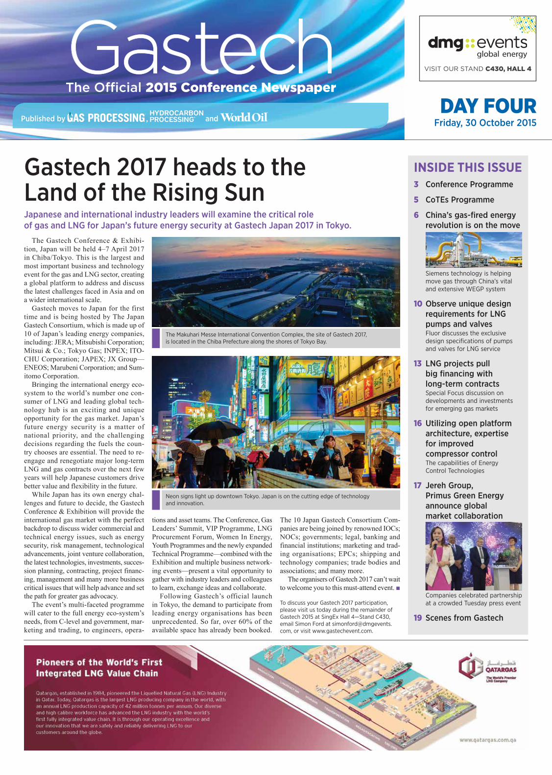
The Makuhari Messe International Convention Complex, the site of Gastech 2017, is located in the Chiba Prefecture along the shores of Tokyo Bay.
Neon signs light up downtown Tokyo. Japan is on the cutting edge of technology and innovation.

Stay Connected to the Latest Technology, News, Projects and Trends in the Global Gas Processing Industry!Gas Processing and GasProcessingNews.com are the newest information platforms from Gulf Publishing Company, publisher of Hydrocarbon Processing and World Oil. Gas Processing covers the latest in process technologies, equipment, operations and maintenance, and environment and regulations pertaining to Natural Gas Liquids (NGLs), Liquefi ed Natural Gas (LNG), Gas-to-Liquids (GTLs) and Liquefi ed Petroleum Gas (LPG). GasProcessingNews.com provides breaking news, market insight, in-depth articles covering the latest developments and advancements in the gas processing industry, project data and more.
GasProcessingNews.com
Technology and Business Information for the Global Gas Processing Industry
Subscribe Today!
Special Supplement to
LNG TECHNOLOGY PLANT DESIGN
Pair NGL recovery with LNG for improved processing
Reduce costs for fired heater purge systems in LNG plants
ENERGY NETWORKSSmall-scale methanol offers
supply flexibility, cost efficiency
Gas-to-power networks bring resources online faster
Technology and Business Information for the Global Gas Processing Industry
GasProcessingNews.com | SEPTEMBER/OCTOBER 2015
Start your FREE SUBSCRIPTION at GasProcessingNews.com
Friday, 30 October 2015 3Gastech Conference Newspaper ■ DAY FOUR
Vice President, Midstream and DownstreamBret Ronk
Gastech ContactsGavin Sutcliffe, Head of Conference
and Governing BodyCharlie Cracknell, Event Director
EditorMike Rhodes
Contributing EditorsKurt AbrahamAdrienne Blume
PhotographerKelly Abraham
Production ManagerAngela Bathe Dietrich
Artist/IllustratorDavid Weeks
Advertising Production ManagerCheryl Willis
AdvertisersABS .............................................................7
ADNOC ..................................................... 4
Construction Boxscore Database ...... 13
dmg::events global energy .............1, 20
Gas Processing .........................................2
Gulf Publishing Company Events ........9
HOEGH LNG ..............................................5
QATARGAS Operating Company ..........1
US Gas Processing Plant Directory ..... 11
www.HydrocarbonProcessing.com
Published by Hydrocarbon Processing as four daily editions, 27–30 October 2015. If you wish to advertise in this newspaper, or to submit a press release, please contact the editor via email at [email protected].
Gastech
2 Greenway Plaza, Suite 1020 Houston, TX 77252-77046 USA+1-713-529-4301
DAY 3 CORRECTIONThe presidency of the International Gas Union passed from Jérôme Ferrier to David C. Carroll in May of this year, following the 26th World Gas Conference in Paris (Gastech Show Daily, Thursday, 29 October 2015, page 7).
FLNG success begins with designADRIENNE BLUME, Gas Processing
At Thursday afternoon’s special focus stream on FLNG innovation, containment and storage, Ian Jewitt, FLNG HSSE Team Lead for Shell Global Solutions, discussed floating LNG (FLNG) engineering in a safety context.
Jewitt explained how Shell has carried out exhaustive risk assessment studies for its Prelude FLNG project. These assessments included hazard identification exercises; quantitative risk assessments; fire, explo-sion and cold spill risk assessments; and ship collision studies, among many others.
Hazard identification. Due to the unique requirements of FLNG vessels, a number of potential hazards must be addressed. These hazards include hydrocar-
bons under pressure, loss of containment, boiler explosions and weather conditions, among many others. “To understand the risks associated with all aspects of FLNG projects, it has been necessary to perform a full range of safety studies,” Jewitt said.
“The layout of the entire facility was based on risk management,” Jewitt said. Along these lines, heavy equipment is sep-arated from personnel living quarters by as much distance as possible to minimize injuries or loss of life from potential fires and explosions.
Safety gap design and spill risks. Prelude’s safety design employs a safety gap philosophy, wherein large safety gaps are implemented between modules. These
safety gaps act as mitigation gaps to reduce the risk of incident escalation.
Another area of concern is cryogenic spill risk. The risk of cryogenic spills is larger on an LNG carrier because of the additional process equipment needed on a floating LNG facility. Shell’s FLNG design minimizes the cryogenic inventory that could potentially be released, reducing the potential contact time of cold liquid spills within critical structures.
Viability of nearshore FLNG. Fol-lowing Jewitt’s talk, Javid Talib, Vice President and FLNG Program Manager for Black & Veatch, examined the factors that make nearshore mid-scale FLNG a viable option.
As an alternative to building a fixed-asset, onshore plant, nearshore FLNG has a shorter construction schedule and can move to commercial operation much faster than a traditional FLNG project. “There’s a need to start conceptual studies right up front,” Talib said. “It’s never too early to start planning.”
Topsides and onshore planning. Design of the topsides begins with technol-ogy selection and decisions on production capacity, train sizes and LNG offloading strategy. Project planners must choose between a single large production train and multiple small production trains. A large single train provides economies of scale and a reduced footprint, but no operational flexibility and complex startup and turn-down issues.
Conversely, the loss of economies of scale found with small multiple trains can be overcome with technology. Small mul-tiple trains have an increased footprint, although the units can be modularized. A multiple-train configuration also yields operational flexibility, easier startup and shutdown, higher availability, dedicated trains for offtake, and production continu-ation during shutdowns.
The VP also noted that the CAPEX for nearshore mid-size FLNG projects is man-ageable, relatively speaking. “The CAPEX is bite-sized and bankable compared to other, larger FLNGs,” he concluded. ■
COMMERCIAL STREAM
MORNINGLNG Projects: Non-Technical Risks, Progress and Delivery
9:00–9:10 Chairperson’s Welcome ■ Chris Clucas, Group Fleet Director,
Bernhard Schulte Shipmanagement Ltd ■ Paul Sullivan, Senior Vice President—
Global LNG and FLNG, WorleyParsons Group
9:10–10:50 PART 1: Global Project Update
9:10–9:35 Managing a Complex, Integrated LNG Project in a Developing Country: The Papua New Guinea (PNG) LNG Project
■ Andrew Barry, Managing Director, ExxonMobil PNG
9:35–10:00 Singapore’s World Class LNG Terminal to Set New Industry Standards and Trends for the Future
■ Dilip Patel, Engineering Manager, Singapore LNG Corporation Pte Ltd
10:00–10:25 Design Innovations and Successful Execution of the Queensland Curtis LNG Project
■ Alasdair Cathcart, General Manager of LNG and Senior Vice President, Bechtel Oil, Gas & Chemicals
10:25–10:50 Opportunities and Challenges of Opening up a New LNG Frontier in Mozambique
■ Ferruccio Taverna, Vice President Mozambique LNG Sales Area Manager of Midstream Gas and Power, Eni
10:50–11:10 Networking and Coffee Break
11:10–12:25 PART 2: Risk, Corporate Social Responsibility and People
11:10–11:35 Social Licence—People Can Stop Projects ■ Mary Lou Lauria, Global Managing Consultant, Environmental
Management and Approvals, WorleyParsons Group
11:35–12:00 Non-Technical Risk Management in Shell’s Integrated Gas Business
■ Karen Westley, General Manager Non-Technical Risk, Shell Integrated Gas
12:00–12:25 The True Cost of a Low-Price LNG Project ■ Heinz Kotzot, LNG Technology Manager, KBR
12:30–13:00 The Gastech Governing Body Wrap-Up and Summary
CONFERENCE AND EXHIBITION OPENING TIMES Conference ExhibitionTuesday 27 October 2015 14:00–17:50 10:00–18:00Wednesday 28 October 2015 09:00–18:00 10:00–19:00Thursday 29 October 2015 09:00–18:00 10:00–18:00Friday 30 October 2015 09:00–13:00 10:00–16:00
Conference Programme
To see the schedule for Centres of Technical Excellence (CoTEs), please see page 5
JAVID TALIB, Vice President and FLNG Program Manager, Black & Veatch
IAN JEWITT, FLNG HSSE Team Lead, Shell Global Solutions
ADNOC daily show.indd 4 9/3/15 11:29 AM
Friday, 30 October 2015 5Gastech Conference Newspaper ■ DAY FOUR
Visit our Gastech stand B520.
Höegh LNG is a leading owner and operator of floating LNG import infrastructure (FSRUs), has developed flexible FLNG design solutions and is an experienced operator of LNG Carriers.
www.hoeghlng.com
Banner Gastech Show Daily 2015.indd 1 07.09.2015 10:01:30
CoTEs—FRIDAY 30 OCTOBER 2015
EXCELLENCE IN GERMAN TECHNOLOGY (Exhibition Theatre A)
INFORMATION AND COMMUNICATION TECHNOLOGY (Exhibition Theatre B)
PIPELINE INFRASTRUCTURE (Exhibition Theatre C)
Introduction 10:15–10:30
Moderator Introductory RemarksMichael Witter, Ambassador, Embassy of the Federal Republic of Germany to Singapore Ragnar Strauch, Director International Markets Process Technology, VDMA German Engineering Federation
Session 1 10:30–10:55
Controlling Valve Pressure in LNG Units and VesselsOlaf Schulernberg, Director Construction and Development, GOETZE Armaturen
Enhanced Security for Oil and Gas Facilities in a Volatile WorldPeter Flynn, Global Business Development Director, Telecoms and Electronics, SNC-Lavalin/Kentz
Towed Pipeline Production SystemsMarin Abelanet, Engineering Director, Asia and Australia, Subsea 7
Session 211:00–11:25
Lessons Learned Solving Pilot Valve Instability Issues on LNG Storage TanksSven Zdun, Sales Manager Southeast Asia, Braunschweiger Flammenfilter GmbH (PROTEGO)
Unidirectional Security Gateways for Natural Gas InfrastructureDimitry Shvartsman, Director of Industrial Security, Waterfall Security Solutions Ltd.
Advanced Magnetic Filtration Makes a Clean Fuel CleanerRoger Simonson, President and CEO, Black Powder Solutions
Session 311:30–11:55
A Review of Non-invasive Techniques for LNG MeasurementPeter Liptrot, Application Engineer, FLEXIM
Intelligent Knowledge Based Operations Advisory and Training Systems to Improve LNG OperationsSankar Selvaraj, HOD—Solutions Research Centre, BSD/SGDC, Yokogawa Electric International Pte Ltd
Evolution of Orifice Metering: Bridging the Technology GapJonathan Page, Technical Sales Manager— UK Facility, Canalta
12:00–12:30 Networking and Coffee Break Safety First Approach and Understanding Pipe-Laying Operations in Different Environment ConditionsJaya Sinnathurai, Pipeline Manager Asia Pacific, Caterpillar Asia Pte Ltd
Session 412:30–12:55
Removing Efficiently Divalent Salts from Meg Reclamation Units—Developing a Tailor-made SolutionDetlef Steidl, Director Application Engineering, BHS-Sonthofen Inc.
Session 5 13:00–13:25
Process Optimization and Safety Issues on Biogas PlantsLutz Hörnschemeyer, Export Manager, Hermann Sewerin GmbH
Closing Remarks 13:25–13:30
Moderator Closing RemarksRagnar Strauch, Director International Markets Process Technology, VDMA German Engineering Federation
CoTEs session preview—Securing oil and gas facilities
During one of Friday morning’s CoTEs Information and Communication Tech-nology in Gas seminars (10:30–10:55), Peter Flynn, Global Business Develop-ment Director, Telecoms and Electronics, SNC-Lavalin/Kentz, will present a case study, “Enhanced security for oil and gas facilities in a volatile world.”
Oil and gas facilities are usually sit-uated in remote locations in areas that are often geo-politically sensitive, with infrastructure that has little, if any, pro-tection. Nonetheless, these facilities need to have personnel onsite and often represent several billions of dollars of investment, making them high in both monetary and strategic value, and at risk of sabotage or attack.
A client requested protection system solutions from such threats for a vast gas field, and the objective was to design a system that would:
• DETECT a potential threat• ASSESS the threat• ACT on the threat.The paper, authored by Albert Aspden,
Chief Engineer (Telecoms), SNC-Lavalin, discusses the technology options consid-ered and the prescribed solution: Using access control systems and CCTV surveil-
lance to protect numerous facilities and major gas pipelines across a geographic area of some 1,300 km2.
Background. The field in question com-prised 120 stations of various sizes, includ-ing warehouses, gas-oil separation plants and water injection plants. The client speci-fied that the security protection system was to provide access control for entrances/exits and fence-line CCTV surveillance, as well as CCTV security surveillance of tens of kilometers of sensitive major pipelines.
While this paper focuses on those par-ticular systems, the FEED also covered elements such as control room modifica-tions, including civil engineering for room extension/modification, acoustic paneling, ceilings, flooring and ergonomics. Con-sideration was also given to HVAC for additional cooling, electrical engineering for power and lighting, specialist telecoms engineering for extension of LAN, access control, CCTV storage and retrieval with video wall, and instrumentation engineer-ing for fire and gas modifications.
Results, observations and con-clusions. Technical challenges included determining the number and location of
cameras to facilitate control room interven-tion and incident response, while overcom-ing limited focal lengths of cameras, poor visibility in a dusty environment, and cam-era tower stability issues. In this vast and remote location, any devices would have to be solar-powered and sufficiently robust to survive the extreme desert environment.
Illuminating 1,300 km2 of video sur-veillance was impractical, so thermal imaging cameras were considered, as well as use of dual technology of both optical and thermal cameras. However, initial cal-culations of camera quantities prescribed by the client meant multiple video feeds monitored by multiple security operators, leading to image overload and compro-mising security.
These constraints lead to a solution based on “blind” surveillance by ground radars integrated with medium- and long-range optical/thermal pan, tilt and zoom cameras, which automatically lock the nearest camera onto any DETECTed tar-get. The security operator is then able to ASSESS and ACT on the target. This solu-tion provides added value by delivering a single view security operator screen when the client’s prescription for multiple views was deemed unworkable.
Already proven in a major gas port facil-ity, the proposed security design provides a robust, effective and efficient solution to ensure the facilities are safeguarded, and that risks are as low as reasonably practi-cable as prescribed by the client. ■
Attend this and other informative CoTEs seminars, and visit the SNC-Lavalin team at #C145 for further discussion.
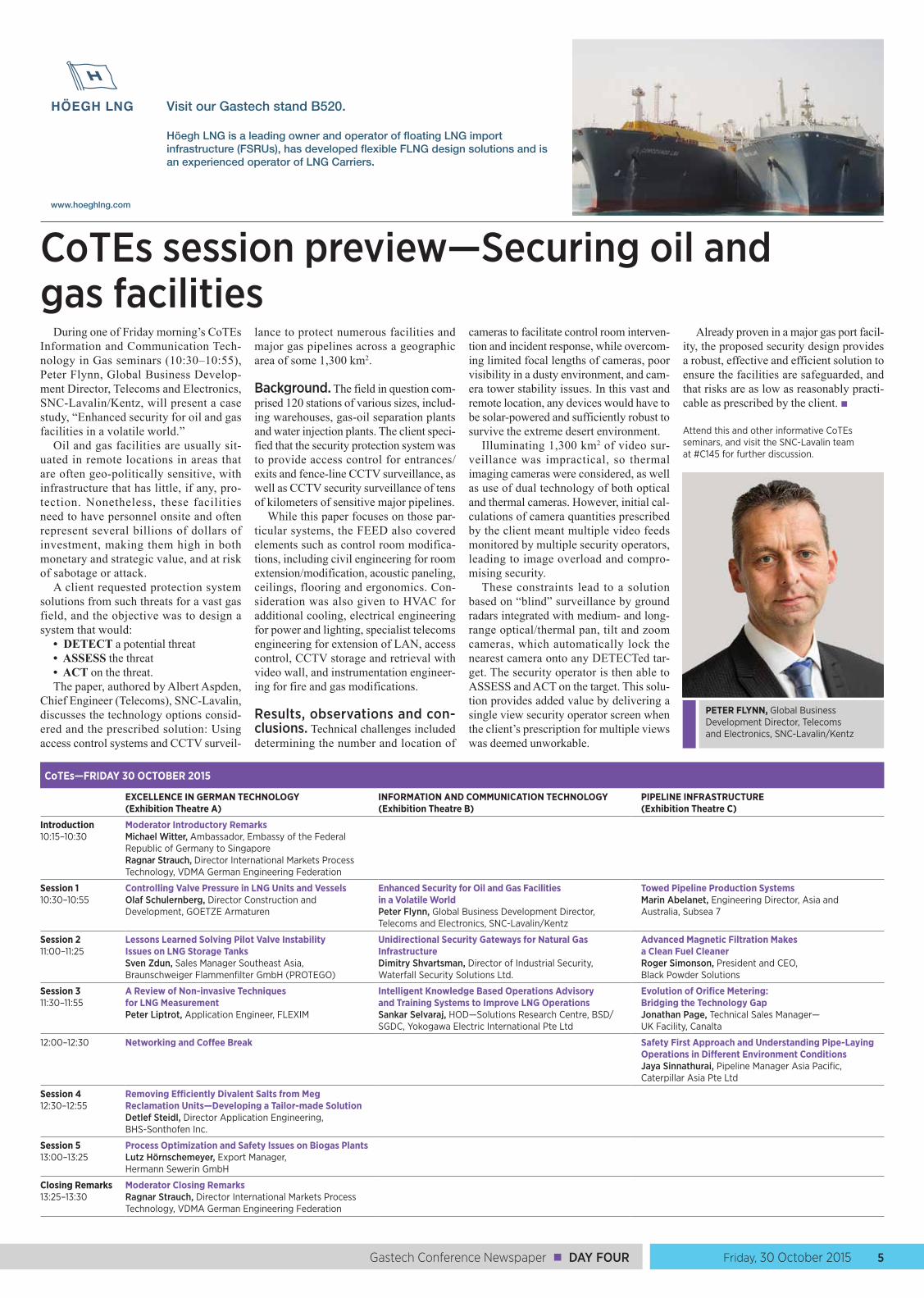
PETER FLYNN, Global Business Development Director, Telecoms and Electronics, SNC-Lavalin/Kentz
DAY FOUR ■ Gastech Conference Newspaper6 Friday, 30 October 2015
China’s gas-fired energy revolution is on the moveMIKE RHODES, Gas Processing
China is the largest consumer of energy in the world: as the economy and GDP grows, so too will the demand for energy. To master this challenge, energy-hungry China needs uninterrupted access to affordable bulk energy, and, to maintain energy security, this must be achieved without substantially increasing dependence on energy imports.
The progression from coal to gas. The country’s high energy self-sufficiency is primarily due to its extensive coal reserves: however, dependency on coal, mainly pro-duced by small and comparatively inef-ficient coal-fired power plants, is the key driver behind high CO2 emissions that have made China the world’s largest emitter. Although it is expanding under a series of Five-Year Plans, gas’s share of the country’s energy mix remains small, despite having the world’s largest technically recoverable shale gas reserves. Recent developments in shale exploration in other countries, particu-larly the US, have increased prospects for a more ambitious shift toward gas, which would cut annual coal consumption by an amount nearly equal to the primary energy demand of the Republic of Korea.
The country is expected to reduce the share of coal-powered generation to 56%
by 2030, while the share of other power sources, such as gas and renewables, would increase. In 2012, gas accounted for only 2% of the total power generation in China; it is estimated that amount will grow to nearly 7% by 2030. The government has set an ambitious goal to have more than 10% gas share in its Total Primary Energy Consumption (TPEC) by the year 2020—that is, almost 400 Bcmy of gas—which will be more than 10% of world gas supply.
This would require further research to adapt the current international drilling techniques to China’s specific and often difficult geological conditions. The China National Petroleum Company (CNPC) is moving quickly to explore domestic shale gas reserves in partnership with interna-tional gas producers such as Royal Dutch Shell and Chevron.
Turning gas into power. The govern-ment has acknowledged these needs and taken many positive steps toward replacing coal with cleaner energy options. One of these solutions is the accelerated construction of highly efficient, gas-powered combined-cycle power plants (CCPP). Experts estimate that the total power generation capacity in China will exceed 2,500 GW in 2030, which
approaches twice the 2014 installed capacity of 1,360 GW. To achieve this, an additional 200 GW of CCPP capacity will be needed. The increased share of power generated by gas-fired power plants would reduce CO2 emissions by 1,320 MMt in 2030, nearly 20% of the estimated CO2 emissions of the country’s power sector in 2030.
The government has instituted a number of aggressive actions to combat the air pol-lution that is prevalent in many of its larger cities, particularly Beijing. The “Beijing Clean Air Action Plan 2013 to 2017” was launched to support this strategy, and Bei-jing Jingxi Gas Thermal Power Co. Ltd. was established to set an example for future combined heat and power (CHP) plants.
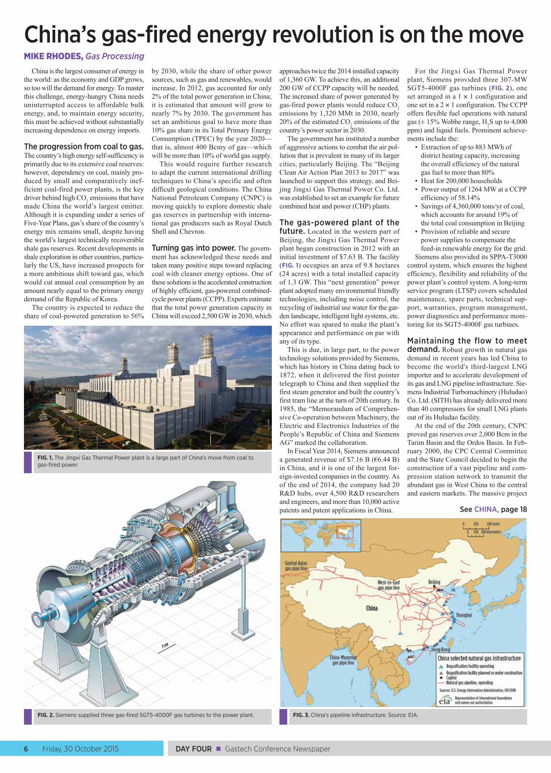
The gas-powered plant of the future. Located in the western part of Beijing, the Jingxi Gas Thermal Power plant began construction in 2012 with an initial investment of $7.63 B. The facility (FIG. 1) occupies an area of 9.8 hectares (24 acres) with a total installed capacity of 1.3 GW. This “next generation” power plant adopted many environmental friendly technologies, including noise control, the recycling of industrial use water for the gar-den landscape, intelligent light systems, etc. No effort was spared to make the plant’s appearance and performance on par with any of its type.
This is due, in large part, to the power technology solutions provided by Siemens, which has history in China dating back to 1872, when it delivered the first pointer telegraph to China and then supplied the first steam generator and built the country’s first tram line at the turn of 20th century. In 1985, the “Memorandum of Comprehen-sive Co-operation between Machinery, the Electric and Electronics Industries of the People’s Republic of China and Siemens AG” marked the collaboration.
In Fiscal Year 2014, Siemens announced a generated revenue of $7.16 B (€6.44 B) in China, and it is one of the largest for-eign-invested companies in the country. As of the end of 2014, the company had 20 R&D hubs, over 4,500 R&D researchers and engineers, and more than 10,000 active patents and patent applications in China.
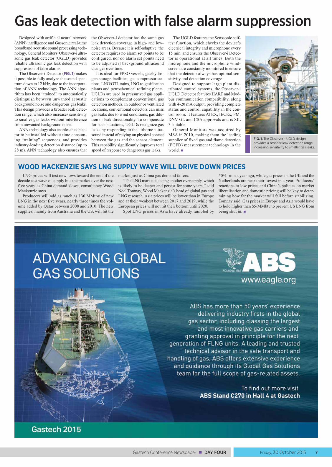
For the Jingxi Gas Thermal Power plant, Siemens provided three 307-MW SGT5-4000F gas turbines (FIG. 2), one set arranged in a 1 × 1 configuration and one set in a 2 × 1 configuration. The CCPP offers flexible fuel operations with natural gas (± 15% Wobbe range, H2S up to 4,000 ppm) and liquid fuels. Prominent achieve-ments include the:
• Extraction of up to 883 MWh of district heating capacity, increasing the overall efficiency of the natural gas fuel to more than 80%
• Heat for 200,000 households• Power output of 1264 MW at a CCPP
efficiency of 58.14%• Savings of 4,360,000 tons/yr of coal,
which accounts for around 19% of the total coal consumption in Beijing
• Provision of reliable and secure power supplies to compensate the feed-in renewable energy for the grid.
Siemens also provided its SPPA-T3000 control system, which ensures the highest efficiency, flexibility and reliability of the power plant’s control system. A long-term service program (LTSP) covers scheduled maintenance, spare parts, technical sup-port, warranties, program management, power diagnostics and performance moni-toring for its SGT5-4000F gas turbines.
Maintaining the flow to meet demand. Robust growth in natural gas demand in recent years has led China to become the world's third-largest LNG importer and to accelerate development of its gas and LNG pipeline infrastructure. Sie-mens Industrial Turbomachinery (Huludao) Co. Ltd. (SITH) has already delivered more than 40 compressors for small LNG plants out of its Huludao facility.
At the end of the 20th century, CNPC proved gas reserves over 2,000 Bcm in the Tarim Basin and the Ordos Basin. In Feb-ruary 2000, the CPC Central Committee and the State Council decided to begin the construction of a vast pipeline and com-pression station network to transmit the abundant gas in West China to the central and eastern markets. The massive project
FIG. 1. The Jingxi Gas Thermal Power plant is a large part of China’s move from coal to gas-fired power.
FIG. 2. Siemens supplied three gas-fired SGT5-4000F gas turbines to the power plant. FIG. 3. China’s pipeline infrastructure. Source: EIA.
See CHINA, page 18
Friday, 30 October 2015 7Gastech Conference Newspaper ■ DAY FOUR
Gas leak detection with false alarm suppressionDesigned with artificial neural network
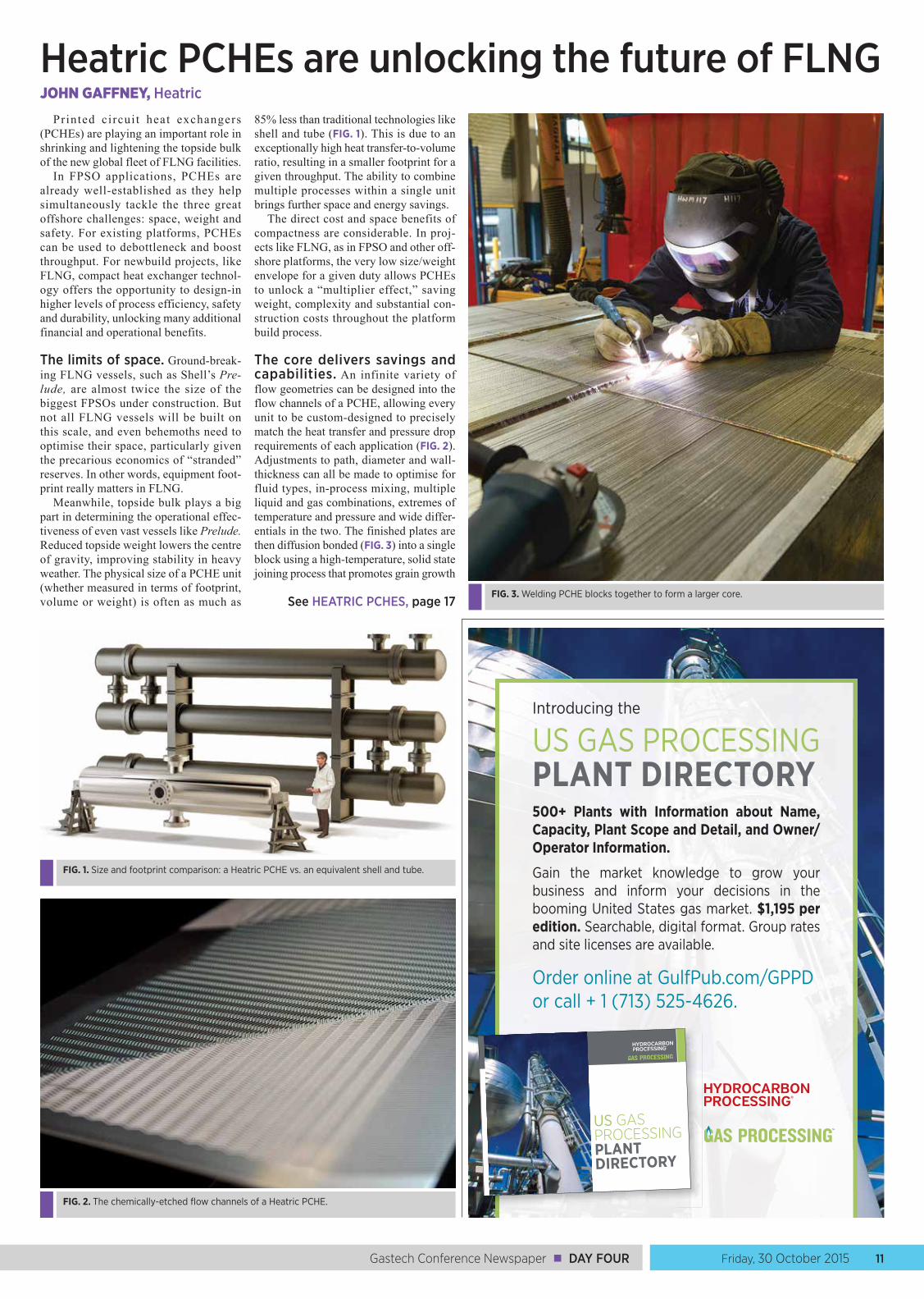
(ANN) intelligence and Gassonic real-time broadband acoustic sound processing tech-nology, General Monitors’ Observer-i ultra-sonic gas leak detector (UGLD) provides reliable ultrasonic gas leak detection with suppression of false alarms.
The Observer-i Detector (FIG. 1) makes it possible to fully analyze the sound spec-trum down to 12 kHz, due to the incorpora-tion of ANN technology. The ANN algo-rithm has been “trained” to automatically distinguish between unwanted acoustic background noise and dangerous gas leaks. This design provides a broader leak detec-tion range, which also increases sensitivity to smaller gas leaks without interference from unwanted background noise.
ANN technology also enables the detec-tor to be installed without time consum-ing “training” sequences, and provides industry-leading detection distance (up to 28 m). ANN technology also ensures that
the Observer-i detector has the same gas leak detection coverage in high- and low-noise areas. Because it is self-adaptive, the detector requires no alarm set points to be configured, nor do alarm set points need to be adjusted if background ultrasound changes over time.
It is ideal for FPSO vessels, gas/hydro-gen storage facilities, gas compressor sta-tions, LNG/GTL trains, LNG re-gasification plants and petrochemical refining plants. UGLDs are used in pressurized gas appli-cations to complement conventional gas detection methods. In outdoor or ventilated locations, conventional detectors can miss gas leaks due to wind conditions, gas dilu-tion or leak directionality. To compensate for such situations, UGLDs recognize gas leaks by responding to the airborne ultra-sound instead of relying on physical contact between the gas and the sensor element. This capability significantly improves total speed of response to dangerous gas leaks.
The UGLD features the Senssonic self-test function, which checks the device’s electrical integrity and microphone every 15 min. and ensures the Observer-i Detec-tor is operational at all times. Both the microphone and the microphone wind-screen are constantly monitored to ensure that the detector always has optimal sen-sitivity and detection coverage.
Designed to support large plant dis-tributed control systems, the Observer-i UGLD Detector features HART and Mod-bus communication compatibility, along with 4-20 mA output, providing complete status and control capability in the con-trol room. It features ATEX, IECEx, FM, DNV GL and CSA approvals and is SIL 3 suitable.
General Monitors was acquired by MSA in 2010, making them the leading supplier of fixed gas and flame detection (FGFD) measurement technology in the world. ■
FIG. 1. The Observer-i UGLD design provides a broader leak detection range, increasing sensitivity to smaller gas leaks.
WOOD MACKENZIE SAYS LNG SUPPLY WAVE WILL DRIVE DOWN PRICESLNG prices will test new lows toward the end of the
decade as a wave of supply hits the market over the next five years as China demand slows, consultancy Wood Mackenzie says.
Producers will add as much as 130 MMtpy of new LNG in the next five years, nearly three times the vol-ume added by Qatar between 2008 and 2010. The new supplies, mainly from Australia and the US, will hit the
market just as China gas demand falters.“The LNG market is facing another oversupply, which
is likely to be deeper and persist for some years,” said Noel Tomnay, Wood Mackenzie’s head of global gas and LNG research. Asia prices will be lower than in Europe and at their weakest between 2017 and 2019, while the European prices will not hit their bottom until 2020.
Spot LNG prices in Asia have already tumbled by
50% from a year ago, while gas prices in the UK and the Netherlands are near their lowest in a year. Producers’ reactions to low prices and China’s policies on market liberalisation and domestic pricing will be key to deter-mining how far the market will fall before stabilizing, Tomnay said. Gas prices in Europe and Asia would have to hold higher than $5/MMbtu to prevent US LNG from being shut in. ■

DAY FOUR ■ Gastech Conference Newspaper8 Friday, 30 October 2015
Small-scale LNG plugs pipeline gaps, complements traditional LNG
Gas Processing spoke to Hasan Dan-dashly, president and CEO of Downstream Technology Solutions for GE Oil and Gas, about the role of small-scale LNG in the evolving natural gas marketplace, the chal-lenges and opportunities for implement-ing small-scale gas processing in different world regions, and the outlook for floating LNG (FLNG).
GP. What do you see as some of the advantages of small- scale LNG vs. large-scale LNG? How is small-scale gas processing transforming the developing world, as well as US infrastructure?
Dandashly. Gas is clearly becoming more abundant in the world. It’s one of the cleanest fuels, and it’s a fairly cost-effec-tive fuel. To capitalize on this gas for many
applications—power generation, indus-try, petrochemical production and trans-portation—a network is required. Often, the network remains the integral part of connecting the source of gas to the points of consumption, such as power, industry, transportation, etc.
The networks that connect these points are made of pipelines, of which the US has an abundance. However, as we know, building new pipelines is not cheap and is time consuming—they have to go through a lot of regulatory hurdles before they are built. LNG tankers (and CNG tankers, for shorter distances) are another part of the network. They enable gas to be liquefied in one part of the world and then moved to another part of the world for consumption.
However, it takes a while to build net-works involving big LNG plants, tankers and pipelines. There are areas where you
can speed up the development of the net-work by liquefying or compressing gas at a small scale, at the point where the gas becomes available, and then transporting it to the point of use. We call this the Vir-tual Pipeline, with alternative transpor-tation methods, such as trucking, taking the place of physical pipelines (FIG. 1). It supplements the network, and the benefits of that supplement and of the small-scale LNG process are faster speed to market and lower CAPEX, so gas demand can be met quickly and cheaply.
There are multiple applications for this technology. In North America, there’s an application in the oil field, which GE has already demonstrated, through a JV with Ferus Natural Gas Fuels, in an agreement with Statoil. In this agreement, the JV is capturing flared gas in the Bakken shale play. We treat the gas, we compress it into CNG using GE technology, and then we move it to the rigs and fracing pumps in the Bakken using Ferus Natural Gas Fuels’ expertise in distribution. This strat-egy is good for the environment because we’re capturing gas that would be flared otherwise, and we’re also saving our cus-tomers money on diesel used to run rigs and fracing pumps.
Other applications for small-scale LNG in North America focus on transportation. With retrofitting, you can use LNG or CNG instead of diesel for heavy-duty trucking, locomotive, marine and mining operations. For some of these vehicles, natural gas can now be both the cargo and the fuel.
Another application in North America is exports. Sometimes there’s less gas available to process, or it’s desirable to begin production at a smaller scale, with
the option of expanding operations in the future, as capital allows. Big LNG plants require large input sources of natural gas and require investment in a large, full-capacity system upfront. But when you have a plant that’s assembled from 10 small-scale LNG trains, its operation and maintenance flexibility can be optimized. In the field, it takes a lot less time to put the modules together. Also, one train can be installed at a time, and the system can be scaled up by adding trains as is neces-sary or financially feasible.
At the international level, it gets very interesting. Small-scale LNG is devel-oping in China and can be implemented within relatively small space constraints (FIG. 2). A lot of transportation in China is driven by natural gas. Since they are developing the market for vehicles and other transportation methods, the demand for new vehicles is higher than in a more saturated market. New vehicles running on natural gas can be sold more easily, which is easier than retrofitting vehicles already on roads. Small-scale LNG also has an advantage in China because, from a regulatory perspective, LNG is taxed and priced differently than regular gasoline, to provide an economic advantage.
In Indonesia, there is a growing need for power and an abundant supply of gas, but transmission grids and pipeline networks are not well developed. Virtual pipeline net-works can provide interim, and sometimes permanent, solutions.
Sub-Saharan Africa is another area in which there’s a lot of gas and a big need for power generation, but there isn’t a suf-ficient pipeline network. In northern Nige-ria, many people’s economic struggles are linked closely to a lack of access to power. By liquefying gas on a small scale and transporting it to areas of need, opera-tors can reach key markets they otherwise couldn’t, more quickly and with less capital investment upfront. A pipeline can be dif-ficult to build and maintain, but a Virtual Pipeline can come online faster, enabling greater agility in the network. This, in turn, can provide power to areas where it was previously unavailable or unreliable.
Small-scale LNG is an exciting space. It’s not an “either/or” with regard to large-scale LNG, though; one doesn’t take away from the other. As gas becomes more avail-able and more prevalent, small-scale lique-faction and compression, and the concept of a Virtual Pipeline, add to the network. The large-scale LNG plants will always be able to operate fairly efficiently and cheaply with large volumes of gas, but they take longer to build and can be more expensive than small-scale LNG plants.
GP. In an ideal scenario, how long does it take to set up a Virtual Pipeline network?
Dandashly. A small-scale LNG plant can be built in about a year. So, from when you start planning the project to the time you have the plant down on the ground and producing, it could be as little as 18 months. Of course, to complete the full supply and demand network, transportation logistics, offtake agreements and customer agree-
FIG. 3. A small-scale LNG plant in Australia.
HASAN DANDASHLY, President and CEO, Downstream Technology Solutions, GE Oil and Gas
FIG. 1. GE’s Virtual Pipeline uses small-scale LNG production and truck delivery of gas to supplement energy networks at a faster speed to market and lower CAPEX.
FIG. 2. A small-scale LNG plant in China.

Friday, 30 October 2015 9Gastech Conference Newspaper ■ DAY FOUR
Gulf Publishing Company and Gas Processing Events Our events provide unique opportunities for speakers, delegates, exhibitors and sponsors to meet face-to-face to discuss the latest industry trends and technological advances.
For information about sponsoring or exhibiting, contact: [email protected].
March 1–2, 2016 | Galveston, TX | EnergyConstructionForum.comEnergy Construction Forum (ECF) is a unique and timely gathering covering all phases of major expansions and new construction projects, with a focus on the challenges and solutions facing the industry today. ECF is the only event that brings together all of the key stakeholders in the rapidly growing energy projects and construction marketplace.
March 2016 | EMGasconference.comEastern Mediterranean Gas Conference (EMGC) will provide attendees with the knowledge and insight necessary to successfully build business operations in this burgeoning region, where an estimated 40 Tcf of recoverable natural gas reserves have been discovered.
April 4–6, 2016 | Houston, TX | OGsupplyChain.comThe inaugural O&G Supply Chain Forum will cover all sectors of the oil and gas supply chain – upstream, midstream and downstream – and the challenges and issues that are specific to each. Attendees will learn to maximize efficiencies, mine savings opportunities and reduce their environmental impact. The event will feature a one-day workshop, a high-level, two-day program, and an exhibit floor.
August 2–3, 2016 | Houston, TX | GTLTechForum.comThe fourth annual GTL Technology Forum will cover the technological and operational advancements in GTL processes that are reducing costs, driving market growth and increasing global activity.
September 13–14, 2016 | Houston, TX | GasProcessingConference.comThe second GasPro Americas will cover natural gas technologies and markets in the Americas. The two-day technology conference will focus on exploring the latest trends, opportunities and challenges in the natural gas sector.
AMERICAS
ments must be in place so that the LNG can be utilized as fuel at the end application.
We can build the plant itself in 9–12 months at the factory, and then it needs to be installed in the field. The modules can be built in many different parts of the world. Likewise, there are major manufacturers for the trucks in many different places.
GP. Small-scale processing solutions offer flexibility, cost effectiveness and speed to market, which are extremely attractive to producers and suppliers, especially in a low-cost environment.
Dandashly. Absolutely. Small-scale LNG does meet those needs. I think the discussion is also moving toward how traditional LNG can utilize modular-ity to achieve greater cost effectiveness. At GE, we have solutions on both ends. We have great capabilities for large-scale LNG, and we have an expertise in building modular solutions. As a case in point, for a large-scale LNG project in Australia, we built modules out of our plant in Italy and shipped them, thereby saving significant costs and time for our customer.
We provide compression for large-scale plants, which is the heart of an LNG train. We have modular capability for our larg-est LNG solution. On the small-scale side, we have complete modular capability, where our preassembled and tested mod-ules (which comprise a large portion of the liquefaction system) are shipped to the site, and the onsite construction company can assemble and commission a complete turn-key train with minimal installation work.
GP. What opportunities do you see for floating LNG, and do you think it will be a key technology trend in the future?
Dandashly. Floating LNG projects, like the Shell [Prelude] project and the Petronas [PFLNG 1] project, are definitely coming. I think they’ll provide flexibility in that, many years from now, when the gas [reserves] are depleted, you can move an FLNG vessel—you don’t have to dismantle it.
We do see that FLNG is an upcoming trend because it provides for that flexibil-ity and modularity, and we are very active in that space, both in our large-scale and small-scale LNG technologies. We’ve sup-ported the Shell and Petronas projects, so we’re active in the major published proj-ects in the FLNG space.
GP. What do you see as the greatest challenges in terms of technology implementation, especially for newer solutions like small-scale processing?
Dandashly. From a technology perspec-tive, I don’t really see that we have any challenges that we can’t overcome with the technology that we have available to us today in the market, and especially inside GE. I think the challenges are more appar-ent in the speed of adoption, because of all of the different players that need to come in, and they all need to come in at the same time to create that new market.
If we take the example of LNG or CNG for trucking, you need to convert the trucks, you need to build the fueling stations and you need to build the com-pression stations—essentially, you need
to build the whole infrastructure. So, it becomes a question of: How quickly can you bring all the players together that are required to provide the solution? In North America, with the oil price being down and the diesel differential not being there, it will create the additional challenge of slowing that process a bit.
However, I think that, over the long term, the technology adoption is happen-ing. In North America, we have abundant gas, so it will make sense to move heavy-duty trucking, locomotives and marine ves-sels into that space. It’s just a question of time, and how all of the players will come together to make it happen.
The example of what we did with Statoil in the Bakken is a good one. Together with Ferus Natural Gas Fuels (which specializes in moving molecules over hard terrain) and GE Ventures (the GE venture capital team that invests), we were able to bring GE technology to Statoil for use in an entirely different context, solving a new problem, which is flare gas reduction and monetizing natural gas as a fuel for oilfield operations. By doing things like this, we create the cat-alyst to get the idea moving, and now we’re taking it from the Bakken to other places.
As we look at Sub-Saharan Africa or Asia, we’re looking at not only how to simply sell GE technology, but also how to bring logistics and the other players together so that we can create a total solution.
You have to speed it up. You can’t make everybody wait for somebody else. At GE, we’re good at doing this, and we’re able to bring these parties together to start proj-ects. The partnerships that you need are dif-ferent in every country, because the players
are different. Technology is global, but the logistics and the EPC companies are differ-ent everywhere, and you need to have the know-how in each country to do this.
GE Oil and Gas operates in 120 coun-tries. Our scale gives us an advantage. So, when we go to Nigeria or to Angola or to Ghana, there are hundreds of employees already there—people who know the mar-ket and who have the relationships with people in that country, or who are from that country—which gives us the ability to move faster in those environments. ■HASAN DANDASHLY has served as the president and CEO of Downstream Technology Solutions for GE Oil & Gas in Houston, Texas, since July 2013. He leads GE Oil & Gas’ newly structured business providing products and services in the traditional downstream, industrial and evolving unconventional resources and distributed gas markets.
Prior to this role, Mr. Dandashly led GE’s Oil & Gas Global Services business since May 2012, based in Florence, Italy. His career started with Honeywell, where he spent 15 years in leadership roles in corporate research, air transport systems, and the industrial automation and control divisions. Mr. Dandashly joined GE in 1998 as a software products manager for GE’s Intelligent Platforms business. In 2000, he moved to GE transportation, where he ran Train Management Systems, a business offering dispatching and planning systems for freight railroads. Following five years in this role, he moved to Qatar in 2005, where he led the development of the company’s new technology center. In 2007, he moved to GE Energy as general manager for Power Generation Services in the Middle East and Africa, based in Dubai.
Mr. Dandashly is a graduate of the Lebanese American University in Beirut, where he obtained a bachelor’s degree in computer science, and of the University of Minnesota in the US, where he received a master’s degree in computer science.

DAY FOUR ■ Gastech Conference Newspaper10 Friday, 30 October 2015
Pumps and valves for LNG service have many exclusive design characteristics and specifications that must be accounted for and followed during the development of an LNG terminal, storage tank or vessel (FIG. 1). Pumps are integrally mounted on the same shaft as the motor, which is sub-merged without coupling or mechanical seals in the LNG liquid.
For retractable, in-tank applications, the pumps can be installed inside the LNG storage tanks in vertical pump columns, with foot valves located at the bottom. This setup removes the possibility of tank leak-age due to piping or other external prob-lems. The pump retraction system permits the unit to be safely removed from an oper-ational tank without venting gas vapor to the atmosphere.
By enclosing the entire unit within a suction vessel built to an appropriate pressure vessel code, such as American Society of Mechanical Engineers (ASME) 8, the system becomes safe and simple. The pump is factory aligned; there are no couplings and no auxiliary pipe work for seal purge, bearing cooling or lubrication. These characteristics make for a light-weight, uncomplicated installation.
The ability to install the pumps inside a storage vessel allows the vessel to be placed underground or to be covered by mounding. This scenario avoids the pos-
sibility of catastrophic failure, and it elimi-nates tank penetrations below the liquid level. It also removes the need for water deluge systems and protects the tanks from being engulfed by fire, radiation, vandal-ism and/or sabotage.
Key factors in the consideration of LNG application pumps are:
1. Lubrication and cooling systems2. Thrust equalizing mechanism3. Bearing configuration4. Junction box (JB) assembly and
electrical penetrations5. Cryodynamic inducer design6. Vibration monitoring systems.
Cryogenic pump specifications. The induction motors in cryogenic appli-cations present certain design, manufactur-ing and testing challenges and advantages when compared to traditional motors. Since the fluid passes through the rotating machine components, specific design and testing parameters have been developed to incorporate the requirements of such low-temperature fluids.
Heat generation in the motor is not a concern when cryogenic fluids are moved. Tests have shown that the stator coils of a submerged cryogenic machine experience a 12°C maximum temperature increase during full-load operation.
Each motor design is project-specific and based on application requirements. Each design is also verified by a perfor-mance test. Motor manufacturing involves proprietary insulation systems, best-in-class techniques and the highest-quality materials to ensure that each unit meets design conditions.
Specifications in the consideration of cryogenic application pumps include:
1. Thrust equalizing2. Bearing configuration3. JB assembly4. Electrical penetrations5. Cryodynamic design requirements6. Vibration monitoring.
Design features of LNG valves. Valves used in LNG service (FIG. 2) are designed with an extended bonnet to avoid packing freezing at operating tempera-tures, and this allows operations to cycle valves when required. Valves manufac-tured for cryogenic applications should comply with the type tested to BS6364 or an equivalent standard; non-metallic materials should be restricted to polytetra-fluoroethylene (PTFE) and graphite.
Fire-safe design to prevent internal leak-age is achieved by using resilient sealing materials that do not decompose or dete-riorate in a fire. In a ball valve, the edge of the metal seat retainer, preloaded by the seat spring, comes into contact with the ball to shut off the line fluid, which mini-mizes internal leakage through the valve bore. The seat retainer also compresses.
The flexible graphite retainer packing prevents fluid leakage from between the valve body and the seat retainer. The appli-cable codes comply with American Petro-leum Institute (API) 607 and API 2218, Fire protecting practices in petroleum and petrochemical plants.
End flanges on valves should comply with ASME B16.5 (for valve diameters up to 24 in.) and with ASME B16.47, Series A (for valve diameters larger than 24 in.). A bidirectional flow sealing mechanism is used so that each of the upstream and downstream seats of the valve is ade-quately maintained in contact with the ball by means of a seat spring. Line pressure further assists with this contact method.
The design of cavity pressure relief is provided to avoid trapped volatile liquid being released into downstream. A shell pressure test should be performed, as per API 598 and ASME B16.34. Test duration should be a minimum of 5 minutes for all valve components, apart from the backseat test, and all valves must undergo a seat clo-sure test.
The supplier must demonstrate that each valve has performed a satisfactory test below –196°C (–230°F), or has been qualified by cryogenic testing for the rep-resentative sizes and ratings proposed. All
raised-face valves must have a smooth surface finish, as per ASME B16.5, with a surface finish range of 125 root mean square (RMS) to 250 RMS, as per ASME B46.1. Ring-type joint-face valves must have a smooth surface finish of 63 RMS.
Face-to-face dimensions of valves should comply with ASME B16.10, ASME BS1873 or ASME API6D. Wall thickness should comply with valve design standards such as API 600, API BS5351 and ASME B16.34. Butt-welded valves must comply with the guidelines listed in ASME B16.25.
Key factors in the consideration of LNG application valves include:
1. The thermal conduction and heat transmission from the low-temperature fluid should be suppressed to a minimum, while a cooling effect is provided with the help of an extension bonnet. The packing is prevented from being exposed to the low-temperature liquid, and a secure seal is achieved.
2. A surface-hardening treatment with a cobalt-chromium alloy is recommended for better performance.
3. A cavity pressure-relief feature should be included.
4. Seat lapping is needed.5. Stem-binding prevention
is achieved with PTFE/perfluoroalkoxy construction.
6. Low-emission-type packing(s) should be used to avoid compression creep stress.
7. The design must prevent abnormal pressure within the cavity.
8. The valve should be designed to experience little to no pressure loss.
9. The valve should have a fire-safe design.
10. The installation of drip-plates should be considered, as needed.
11. All welded sections should be 100% radio-graphed, and a die-penetration test should be conducted.
12. Full traceability of the materials used, along with their compositions, is required for pressure-retaining components—i.e., body, cover, extended bonnet, bolting, shaft, seat and disc, including the ball.
13. A chemical composition analysis of each cast/melt and heat batch is required for all pressure-retaining cast/forged or bar sections.
14. All components must be impact tested per ASME 8, Division 1, at –196°C. ■
GOBIND KHIANI has spent more than 20 years in the energy and power business, with more than 10 years of experience in western Canada’s oil and gas industry, and additional experience in the UK and Dubai. He is based out of Calgary, Alberta. He graduated from the University of Poona in India and completed his master’s degree in materials and mechanical engineering from the University of Calgary in Alberta, Canada. He is a registered professional engineer working in the western provinces and prairies of Canada.
Observe unique design requirements for LNG pumps and valvesG. KHIANI, Fluor Canada Ltd.
FIG. 1. Diagram of a vessel used in the transport of LNG.
FIG. 2. A valve used in LNG service. Photo courtesy of Bray Valves USA.
ABS TO CLASS FIRST LNG CARRIERS WITH KOGAS KC-1
ABS, a leading provider of classification services to the global marine and off-shore industries, has been selected to class two LLNG carriers (LNGCs) for SK Shipping, featuring the KC-1 cargo containment system (CCS).
The agreement brings to five the number of LNGCs to be built to joint ABS/KR class for Korea Gas Corporation (KOGAS), the world’s largest LNG importer.
Two 174,000-m3 LNGCs will be built with the KOGAS-developed KC-1 CCS for SK Shipping at the Samsung Heavy Industries yard in South Korea. An addi-tional three 174,000-m3 LNGCs featuring the No. 96-type CCS—two for Korea Line Corporation and one for Hyundai LNG Shipping—will be built at Daewoo Shipbuilding and Marine Engineering.
Upon delivery, the ships will be chartered to KOGAS and will carry shale gas from the US to South Korea beginning in 2017.
KOGAS developed the KC-1 CCS in a seven-year joint development project with shipyards Hyundai, Samsung and Daewoo. The primary KC-1 concept is to minimize the impact of primary barrier deformation on the insulation system from the hull. The system uses 1.5-mm corrugated stainless steel membrane as the pri-mary and secondary barriers, and polyurethane foam with a density of 115 kg/m3 as the insulating material, an arrangement normally used in shore-based storage.
ABS issued an extended approval in principal and general design approval for the system in 2014. ■
Friday, 30 October 2015 11Gastech Conference Newspaper ■ DAY FOUR
Heatric PCHEs are unlocking the future of FLNGJOHN GAFFNEY, Heatric
Printed circui t heat exchangers (PCHEs) are playing an important role in shrinking and lightening the topside bulk of the new global fleet of FLNG facilities.
In FPSO applications, PCHEs are already well-established as they help simultaneously tackle the three great offshore challenges: space, weight and safety. For existing platforms, PCHEs can be used to debottleneck and boost throughput. For newbuild projects, like FLNG, compact heat exchanger technol-ogy offers the opportunity to design-in higher levels of process efficiency, safety and durability, unlocking many additional financial and operational benefits.
The limits of space. Ground-break-ing FLNG vessels, such as Shell’s Pre-lude, are almost twice the size of the biggest FPSOs under construction. But not all FLNG vessels will be built on this scale, and even behemoths need to optimise their space, particularly given the precarious economics of “stranded” reserves. In other words, equipment foot-print really matters in FLNG.
Meanwhile, topside bulk plays a big part in determining the operational effec-tiveness of even vast vessels like Prelude. Reduced topside weight lowers the centre of gravity, improving stability in heavy weather. The physical size of a PCHE unit (whether measured in terms of footprint, volume or weight) is often as much as
85% less than traditional technologies like shell and tube (FIG. 1). This is due to an exceptionally high heat transfer-to-volume ratio, resulting in a smaller footprint for a given throughput. The ability to combine multiple processes within a single unit brings further space and energy savings.
The direct cost and space benefits of compactness are considerable. In proj-ects like FLNG, as in FPSO and other off-shore platforms, the very low size/weight envelope for a given duty allows PCHEs to unlock a “multiplier effect,” saving weight, complexity and substantial con-struction costs throughout the platform build process.
The core delivers savings and capabilities. An infinite variety of flow geometries can be designed into the flow channels of a PCHE, allowing every unit to be custom-designed to precisely match the heat transfer and pressure drop requirements of each application (FIG. 2). Adjustments to path, diameter and wall-thickness can all be made to optimise for fluid types, in-process mixing, multiple liquid and gas combinations, extremes of temperature and pressure and wide differ-entials in the two. The finished plates are then diffusion bonded (FIG. 3) into a single block using a high-temperature, solid state joining process that promotes grain growth
Introducing the
US GAS PROCESSING PLANT DIRECTORY 500+ Plants with Information about Name, Capacity, Plant Scope and Detail, and Owner/Operator Information.
Gain the market knowledge to grow your business and inform your decisions in the booming United States gas market. $1,195 per edition. Searchable, digital format. Group rates and site licenses are available.
Order online at GulfPub.com/GPPD or call + 1 (713) 525-4626.
US GAS PROCESSING PLANT DIRECTORY
FIG. 1. Size and footprint comparison: a Heatric PCHE vs. an equivalent shell and tube.
FIG. 2. The chemically-etched flow channels of a Heatric PCHE.
FIG. 3. Welding PCHE blocks together to form a larger core.See HEATRIC PCHES, page 17
DAY FOUR ■ Gastech Conference Newspaper12 Friday, 30 October 2015
In today’s low-oil-price environment, energy operating and service companies are finding synergies in mergers and acqui-sitions to create added value and to reduce costs. The same holds true for natural gas-focused companies.
Whether gas is developed as associated gas from oil wells, produced from gas and condensate wells, or discovered as stranded gas in remote or harsh environments, the best way to optimize the value of gas is to move it to consumers in a high-demand form. In many regions around the world, that form is liquid fuels. As a historical leader in GTL technology, Black & Veatch (B&V) is ramping up its capabilities to serve this growing market.
In the fourth quarter of 2014, B&V and Emerging Fuels Technology (EFT) joined forces to improve the speed-to-market, cost-effectiveness and reliable pathways to implement GTL projects. The agreement covers projects that use a variety of feed-stocks, including natural gas, municipal solid waste, biomass and coal, which are often collectively referred to as XTL.
Under one aspect of the agreement, B&V will apply its expertise in EPC proj-ect execution, as well as in modular and skid-mounted design and standardiza-tion, to develop and implement packaged designs for small-scale GTL and XTL plants with design sizes ranging from 500 bpd to 10 Mbpd. The packaged designs, which use shop-fabricated modules that can be shipped by truck, result in reduced project costs and timelines.
Gas Processing spoke with B&V’s vice president and manager of oil and gas, Doug Miller, about the state of the industry and what lies ahead for GTL technology.
GP. How long has B&V been designing GTL systems?
Miller. B&V began participating in GTL plant designs in the early 1990s. The com-pany has professionals with project experi-ence dating back to the 1980s. Our experi-enced professionals have been instrumental in working with catalyst and technology suppliers, such as EFT, which has a proven, licensed technology and a patented catalyst for producing GTL products from syngas.
As a team, B&V and EFT are creat-ing and developing GTL solutions for the
industry and maximizing the strengths of each organization. As part of this contin-ued emphasis on growth plans for the GTL industry, and with responsibilities as part of the B&V oil and gas business line, B&V and EFT are involved daily in the develop-ment and advancement of GTL technology and are excited about the future potential for the industry.
Our GTL process knowledge, coupled with our EPC project execution, allows B&V to participate from early feasibility studies through detailed engineering, com-missioning, startup and performance test-ing of facilities.
GP. How has GTL plant design and technology evolved over time?
Miller. Companies are continuously searching for means to find solutions that address cost, scheduling and attractive eco-nomics. Technology companies like EFT continue to address more capital-efficient process designs, catalyst productivity, cat-alyst life and the ability to produce high yields at favorable conditions.
Engineering companies often look for ways to package equipment in skids and to standardize, where feasible, to make repeat-able designs for future units to reduce over-all plant cost and scheduling. Looking at this from an industry perspective, GTL has continued to spark interest as companies and environmental demands evolve to reduce emissions from oil and gas operations.
Also, flared gas regulations are driving demand for capture, and GTL is a potential solution. Cleaner transportation fuels gener-ated from Fischer-Tropsch (FT) synthesis of syngas are becoming an environmentally desirable way to reduce fuel burn emissions.
Furthermore, engines are benefitting from performance improvements, as well as from the use of synthetic lubricants gen-erated from synthetic crude oil.
GP. How has the EPC of modular GTL facilities changed over time?
Miller. The evolution of the technology, and the approach to streamlined costs and schedules for facilities, have resulted in a greater demand to find skid-packaging and modular-construction solutions.
Factors include providing construc-tion in remote locations, where resources and site-specific issues make construction more difficult and costly. Also, the indus-try has experienced times when construc-tion resources were constrained. The use of skids or modules in such a situation helps reduce field hours for construction.
Additionally, the use of skids and mod-ules has increased to accommodate the con-cept of offshore applications, where plac-ing modules on a floating unit is desirable. Developing skids and standardizing sizes also aids in repeatability and flexibility to deliver a product to market faster.
GP. What type of catalysts for GTL technology are the most economical?
Miller. GTL catalysts for FT reactions are generally active metals, such as iron or
cobalt, with promoters, such as noble met-als or oxides. These GTL catalysts are gen-erally found with various supports, such as alumina, silica or titanium.
Economics are a function of project drivers and decisions that the end users must factor into their determination for selection. One selection might be less expensive than another, yet may not pro-vide the same productivity or yields and may be less active.
To assess the economics for catalyst choices, it is important to be aware of the overall project economics and drivers for selection. For example, the EFT catalyst is highly productive and active, and the favorable economics have resulted in it being selected for various projects. The EFT catalyst is commercially available for use on GTL projects.
GP. Is GTL a good solution for stranded gas in remote locations and harsh environments?
Miller. Yes. The potential and volume of stranded gas in remote locations make GTL an attractive option for those types of applications. It is important to assess the volume of the stranded gas in various fields to couple the appropriate size and number of GTL facilities for that field. Facility capacity can be constructed and adjusted to match the field size.
Stranded gas is also a viable means for skids and modules, depending on the loca-tion, the field size and the GTL volume required. Utilizing GTL for these stranded fields is an appealing means of develop-ing them.
For these locations, the infrastructure, product handling and transportation of the GTL liquids require close evaluation.
GP. Has the oil price drop affected the GTL market?
Miller. The reduction in oil prices has impacted the economy as a whole, from a gas processing perspective. While transpor-tation-type GTL fuels derived from natural gas have seen reduced margins, specialty products derived from the GTL process have higher margins and have not realized the same impact. Projects to upgrade GTL products to lubricants and waxes have an opportunity despite the lower oil prices due to these higher product margins.
Additionally, the GTL business has the versatility to produce GTL liquids from feed sources other than natural gas, result-ing in a generation of valuable products that are less sensitive to oil prices.
Furthermore, environmental drivers to reduce emissions can also support GTL production that is less sensitive to oil prices. Lubricants from GTL are more environmentally friendly than traditional oil-based lubricants.
GTL simply requires syngas as a feed-stock for the reaction. There are a multitude of other markets, aside from oil-based driv-ers, to create a starting-point feedstock for GTL synthesis, such as biomass, flared and stranded gas, and other zero-carbon-fuel or low-carbon-fuel feedstocks.
GP. What are the biggest challenges and solutions for companies that want to acquire and operate GTL facilities?
Miller. Two key challenges are, first, establishing the infrastructure to address the gas supply and the liquid products and, second, developing an economic, attractive solution for the overall facility.
The first challenge that the industry is facing is to develop the infrastructure to accommodate the liquids generated at pro-posed GTL facilities on the product end. Pipelines often are not available to accom-modate these syncrude or lubricant prod-ucts. Instead, facilities are handling these products via rail or trucking.
Another challenge is to develop the gas gathering and collection facilities to feed smaller GTL units in remote locations where stranded gas exists or where wells are presently shut in.
Second, finding a solution to satisfy the economics of the facility is a problem that companies are facing while oil prices are depressed. However, through creative tech-nologies like skid packaging, as well as developing specialty product lines, B&V and EFT offer solutions that are attracting attention due to favorable economics.
GP. What new or next-generation GTL technology will B&V roll out in the near future?
Miller. Stay tuned through the year as B&V and EFT release information on the FLARE BUSTER plant design. This con-cept is designed to utilize stranded gas or flared gas on smaller-scale volumes, such as through individual plants in the 500-bpd to 1,000-bpd range that are capable of pro-ducing GTL products.
The FLARE BUSTER design will be a skid-based, transportable solution to achieve flexibility in installation and relo-cation, as well as to reduce construction challenges in remote locations. This will result in emissions-control benefits for locations that are heavy in gas flaring. It will also provide a way to produce at wells that are shut in because of insufficient means to consume the produced gas. ■
DOUG MILLER is vice president and business line manager of oil and gas operations for Black & Veatch. Mr. Miller is responsible for execution oversight for the oil and gas business line within B&V’s energy business, ensuring that project team activities reach successful execution, including cost and schedule objectives, as well as safety and quality plans, for the entire scope of work.
Mr. Miller assists business development activities that address the full realm of midstream gas processing involving treating, NGL recovery, fractionation and activities for other means of monetizing natural gas, such as GTL technology.
Mr. Miller previously served as the process chemical department manager for B&V. Prior to that role, he held positions over 24 years as a project manager, chief engineer, engineering manager and principal process engineer.
Mr. Miller began his career as a chemical engineer for Eastman Kodak in Longview, Texas. He is a registered professional engineer in Kansas.
Black & Veatch forms GTL partnership to solve processing challengesDOUG MILLER, Black & Veatch
DOUG MILLER, vice president and business line manager of oil and gas operations for Black & Veatch (B&V)
Friday, 30 October 2015 13Gastech Conference Newspaper ■ DAY FOUR
www.ConstructionBoxscore.com
THE FUTURE OF DOWNSTREAM PROJECT INTELLIGENCE
Market Intelligence for the Global Refi ning, Petrochemical and Gas Processing/LNG industries
Project details on thousands of active projects and construction contracts in the global refi ning, petrochemical, gas processing, LNG and solids industries
Advanced search, including by project type, scope, region, investment and more
Daily updates for new and updated projects
The Weekly Boxscore Update e-newsletters
Relied upon and trusted by HPI professionals for more than 60 years
For more information, contact J’Nette Davis-Nichols, Specialized Products Manager, at +1 (713) 520-4426 or [email protected]
Welcome to the NEW Construction Boxscore Database
Logon to ConstructionBoxscore.com today!
LNG projects pull big financing with long-term contractsADRIENNE BLUME, Gas Processing
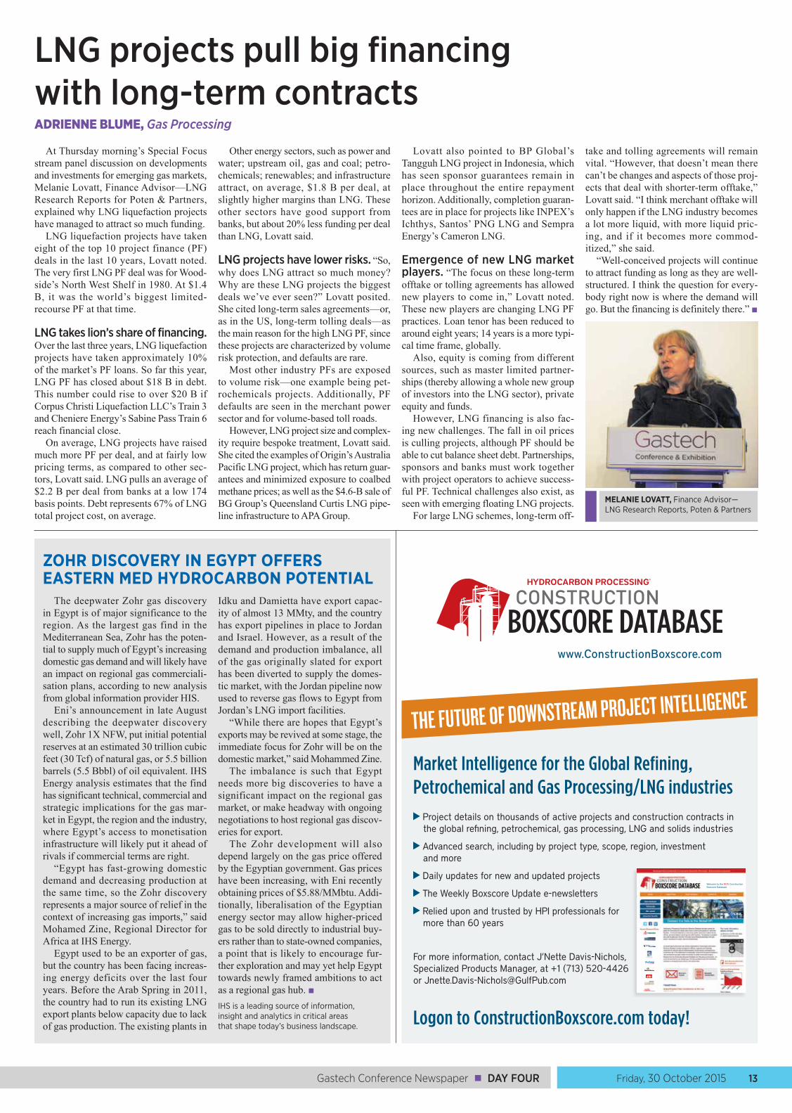
At Thursday morning’s Special Focus stream panel discussion on developments and investments for emerging gas markets, Melanie Lovatt, Finance Advisor—LNG Research Reports for Poten & Partners, explained why LNG liquefaction projects have managed to attract so much funding.
LNG liquefaction projects have taken eight of the top 10 project finance (PF) deals in the last 10 years, Lovatt noted. The very first LNG PF deal was for Wood-side’s North West Shelf in 1980. At $1.4 B, it was the world’s biggest limited-recourse PF at that time.
LNG takes lion’s share of financing. Over the last three years, LNG liquefaction projects have taken approximately 10% of the market’s PF loans. So far this year, LNG PF has closed about $18 B in debt. This number could rise to over $20 B if Corpus Christi Liquefaction LLC’s Train 3 and Cheniere Energy’s Sabine Pass Train 6 reach financial close.
On average, LNG projects have raised much more PF per deal, and at fairly low pricing terms, as compared to other sec-tors, Lovatt said. LNG pulls an average of $2.2 B per deal from banks at a low 174 basis points. Debt represents 67% of LNG total project cost, on average.
Other energy sectors, such as power and water; upstream oil, gas and coal; petro-chemicals; renewables; and infrastructure attract, on average, $1.8 B per deal, at slightly higher margins than LNG. These other sectors have good support from banks, but about 20% less funding per deal than LNG, Lovatt said.
LNG projects have lower risks. “So, why does LNG attract so much money? Why are these LNG projects the biggest deals we’ve ever seen?” Lovatt posited. She cited long-term sales agreements—or, as in the US, long-term tolling deals—as the main reason for the high LNG PF, since these projects are characterized by volume risk protection, and defaults are rare.
Most other industry PFs are exposed to volume risk—one example being pet-rochemicals projects. Additionally, PF defaults are seen in the merchant power sector and for volume-based toll roads.
However, LNG project size and complex-ity require bespoke treatment, Lovatt said. She cited the examples of Origin’s Australia Pacific LNG project, which has return guar-antees and minimized exposure to coalbed methane prices; as well as the $4.6-B sale of BG Group’s Queensland Curtis LNG pipe-line infrastructure to APA Group.
Lovatt also pointed to BP Global’s Tangguh LNG project in Indonesia, which has seen sponsor guarantees remain in place throughout the entire repayment horizon. Additionally, completion guaran-tees are in place for projects like INPEX’s Ichthys, Santos’ PNG LNG and Sempra Energy’s Cameron LNG.
Emergence of new LNG market players. “The focus on these long-term offtake or tolling agreements has allowed new players to come in,” Lovatt noted. These new players are changing LNG PF practices. Loan tenor has been reduced to around eight years; 14 years is a more typi-cal time frame, globally.
Also, equity is coming from different sources, such as master limited partner-ships (thereby allowing a whole new group of investors into the LNG sector), private equity and funds.
However, LNG financing is also fac-ing new challenges. The fall in oil prices is culling projects, although PF should be able to cut balance sheet debt. Partnerships, sponsors and banks must work together with project operators to achieve success-ful PF. Technical challenges also exist, as seen with emerging floating LNG projects.
For large LNG schemes, long-term off-
take and tolling agreements will remain vital. “However, that doesn’t mean there can’t be changes and aspects of those proj-ects that deal with shorter-term offtake,” Lovatt said. “I think merchant offtake will only happen if the LNG industry becomes a lot more liquid, with more liquid pric-ing, and if it becomes more commod-itized,” she said.
“Well-conceived projects will continue to attract funding as long as they are well-structured. I think the question for every-body right now is where the demand will go. But the financing is definitely there.” ■
MELANIE LOVATT, Finance Advisor— LNG Research Reports, Poten & Partners
ZOHR DISCOVERY IN EGYPT OFFERS EASTERN MED HYDROCARBON POTENTIAL
The deepwater Zohr gas discovery in Egypt is of major significance to the region. As the largest gas find in the Mediterranean Sea, Zohr has the poten-tial to supply much of Egypt’s increasing domestic gas demand and will likely have an impact on regional gas commerciali-sation plans, according to new analysis from global information provider HIS.
Eni’s announcement in late August describing the deepwater discovery well, Zohr 1X NFW, put initial potential reserves at an estimated 30 trillion cubic feet (30 Tcf) of natural gas, or 5.5 billion barrels (5.5 Bbbl) of oil equivalent. IHS Energy analysis estimates that the find has significant technical, commercial and strategic implications for the gas mar-ket in Egypt, the region and the industry, where Egypt’s access to monetisation infrastructure will likely put it ahead of rivals if commercial terms are right.
“Egypt has fast-growing domestic demand and decreasing production at the same time, so the Zohr discovery represents a major source of relief in the context of increasing gas imports,” said Mohamed Zine, Regional Director for Africa at IHS Energy.
Egypt used to be an exporter of gas, but the country has been facing increas-ing energy deficits over the last four years. Before the Arab Spring in 2011, the country had to run its existing LNG export plants below capacity due to lack of gas production. The existing plants in
Idku and Damietta have export capac-ity of almost 13 MMty, and the country has export pipelines in place to Jordan and Israel. However, as a result of the demand and production imbalance, all of the gas originally slated for export has been diverted to supply the domes-tic market, with the Jordan pipeline now used to reverse gas flows to Egypt from Jordan’s LNG import facilities.
“While there are hopes that Egypt’s exports may be revived at some stage, the immediate focus for Zohr will be on the domestic market,” said Mohammed Zine.
The imbalance is such that Egypt needs more big discoveries to have a significant impact on the regional gas market, or make headway with ongoing negotiations to host regional gas discov-eries for export.
The Zohr development will also depend largely on the gas price offered by the Egyptian government. Gas prices have been increasing, with Eni recently obtaining prices of $5.88/MMbtu. Addi-tionally, liberalisation of the Egyptian energy sector may allow higher-priced gas to be sold directly to industrial buy-ers rather than to state-owned companies, a point that is likely to encourage fur-ther exploration and may yet help Egypt towards newly framed ambitions to act as a regional gas hub. ■IHS is a leading source of information, insight and analytics in critical areas that shape today’s business landscape.
DAY FOUR ■ Gastech Conference Newspaper14 Friday, 30 October 2015
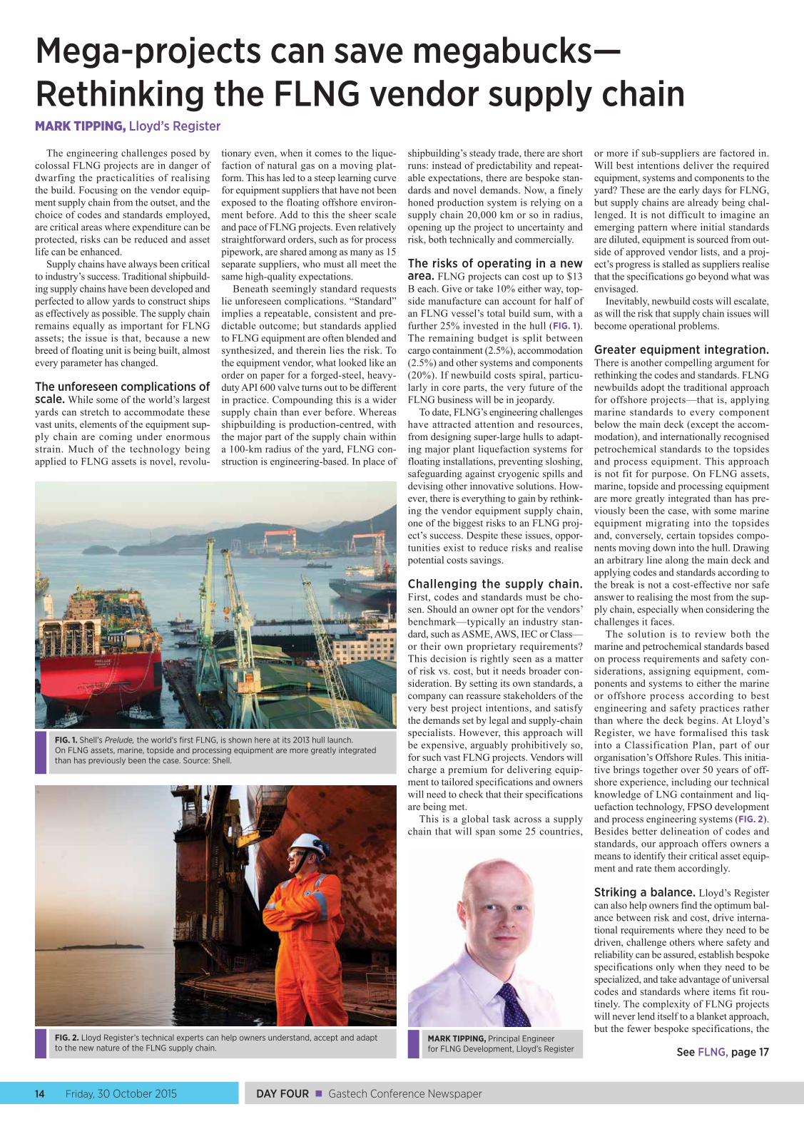
The engineering challenges posed by colossal FLNG projects are in danger of dwarfing the practicalities of realising the build. Focusing on the vendor equip-ment supply chain from the outset, and the choice of codes and standards employed, are critical areas where expenditure can be protected, risks can be reduced and asset life can be enhanced.
Supply chains have always been critical to industry’s success. Traditional shipbuild-ing supply chains have been developed and perfected to allow yards to construct ships as effectively as possible. The supply chain remains equally as important for FLNG assets; the issue is that, because a new breed of floating unit is being built, almost every parameter has changed.
The unforeseen complications of scale. While some of the world’s largest yards can stretch to accommodate these vast units, elements of the equipment sup-ply chain are coming under enormous strain. Much of the technology being applied to FLNG assets is novel, revolu-
tionary even, when it comes to the lique-faction of natural gas on a moving plat-form. This has led to a steep learning curve for equipment suppliers that have not been exposed to the floating offshore environ-ment before. Add to this the sheer scale and pace of FLNG projects. Even relatively straightforward orders, such as for process pipework, are shared among as many as 15 separate suppliers, who must all meet the same high-quality expectations.
Beneath seemingly standard requests lie unforeseen complications. “Standard” implies a repeatable, consistent and pre-dictable outcome; but standards applied to FLNG equipment are often blended and synthesized, and therein lies the risk. To the equipment vendor, what looked like an order on paper for a forged-steel, heavy-duty API 600 valve turns out to be different in practice. Compounding this is a wider supply chain than ever before. Whereas shipbuilding is production-centred, with the major part of the supply chain within a 100-km radius of the yard, FLNG con-struction is engineering-based. In place of
shipbuilding’s steady trade, there are short runs: instead of predictability and repeat-able expectations, there are bespoke stan-dards and novel demands. Now, a finely honed production system is relying on a supply chain 20,000 km or so in radius, opening up the project to uncertainty and risk, both technically and commercially.
The risks of operating in a new area. FLNG projects can cost up to $13 B each. Give or take 10% either way, top-side manufacture can account for half of an FLNG vessel’s total build sum, with a further 25% invested in the hull (FIG. 1). The remaining budget is split between cargo containment (2.5%), accommodation (2.5%) and other systems and components (20%). If newbuild costs spiral, particu-larly in core parts, the very future of the FLNG business will be in jeopardy.
To date, FLNG’s engineering challenges have attracted attention and resources, from designing super-large hulls to adapt-ing major plant liquefaction systems for floating installations, preventing sloshing, safeguarding against cryogenic spills and devising other innovative solutions. How-ever, there is everything to gain by rethink-ing the vendor equipment supply chain, one of the biggest risks to an FLNG proj-ect’s success. Despite these issues, oppor-tunities exist to reduce risks and realise potential costs savings.
Challenging the supply chain. First, codes and standards must be cho-sen. Should an owner opt for the vendors’ benchmark—typically an industry stan-dard, such as ASME, AWS, IEC or Class—or their own proprietary requirements? This decision is rightly seen as a matter of risk vs. cost, but it needs broader con-sideration. By setting its own standards, a company can reassure stakeholders of the very best project intentions, and satisfy the demands set by legal and supply-chain specialists. However, this approach will be expensive, arguably prohibitively so, for such vast FLNG projects. Vendors will charge a premium for delivering equip-ment to tailored specifications and owners will need to check that their specifications are being met.
This is a global task across a supply chain that will span some 25 countries,
or more if sub-suppliers are factored in. Will best intentions deliver the required equipment, systems and components to the yard? These are the early days for FLNG, but supply chains are already being chal-lenged. It is not difficult to imagine an emerging pattern where initial standards are diluted, equipment is sourced from out-side of approved vendor lists, and a proj-ect’s progress is stalled as suppliers realise that the specifications go beyond what was envisaged.
Inevitably, newbuild costs will escalate, as will the risk that supply chain issues will become operational problems.
Greater equipment integration. There is another compelling argument for rethinking the codes and standards. FLNG newbuilds adopt the traditional approach for offshore projects—that is, applying marine standards to every component below the main deck (except the accom-modation), and internationally recognised petrochemical standards to the topsides and process equipment. This approach is not fit for purpose. On FLNG assets, marine, topside and processing equipment are more greatly integrated than has pre-viously been the case, with some marine equipment migrating into the topsides and, conversely, certain topsides compo-nents moving down into the hull. Drawing an arbitrary line along the main deck and applying codes and standards according to the break is not a cost-effective nor safe answer to realising the most from the sup-ply chain, especially when considering the challenges it faces.
The solution is to review both the marine and petrochemical standards based on process requirements and safety con-siderations, assigning equipment, com-ponents and systems to either the marine or offshore process according to best engineering and safety practices rather than where the deck begins. At Lloyd’s Register, we have formalised this task into a Classification Plan, part of our organisation’s Offshore Rules. This initia-tive brings together over 50 years of off-shore experience, including our technical knowledge of LNG containment and liq-uefaction technology, FPSO development and process engineering systems (FIG. 2). Besides better delineation of codes and standards, our approach offers owners a means to identify their critical asset equip-ment and rate them accordingly.
Striking a balance. Lloyd’s Register can also help owners find the optimum bal-ance between risk and cost, drive interna-tional requirements where they need to be driven, challenge others where safety and reliability can be assured, establish bespoke specifications only when they need to be specialized, and take advantage of universal codes and standards where items fit rou-tinely. The complexity of FLNG projects will never lend itself to a blanket approach, but the fewer bespoke specifications, the
Mega-projects can save megabucks—Rethinking the FLNG vendor supply chainMARK TIPPING, Lloyd’s Register
FIG. 1. Shell’s Prelude, the world’s first FLNG, is shown here at its 2013 hull launch. On FLNG assets, marine, topside and processing equipment are more greatly integrated than has previously been the case. Source: Shell.
FIG. 2. Lloyd Register’s technical experts can help owners understand, accept and adapt to the new nature of the FLNG supply chain.
MARK TIPPING, Principal Engineer for FLNG Development, Lloyd’s Register See FLNG, page 17
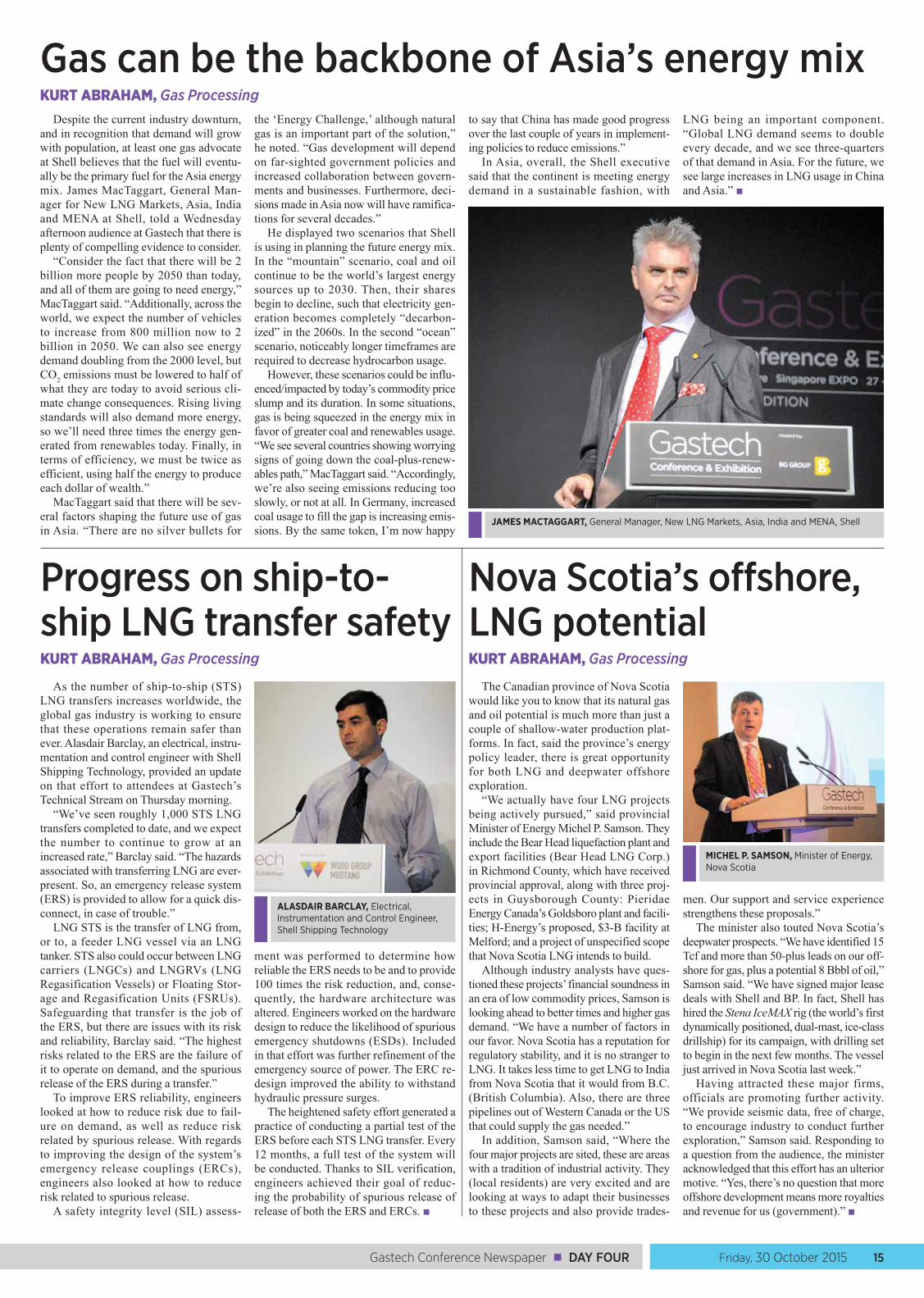
Friday, 30 October 2015 15Gastech Conference Newspaper ■ DAY FOUR
Despite the current industry downturn, and in recognition that demand will grow with population, at least one gas advocate at Shell believes that the fuel will eventu-ally be the primary fuel for the Asia energy mix. James MacTaggart, General Man-ager for New LNG Markets, Asia, India and MENA at Shell, told a Wednesday afternoon audience at Gastech that there is plenty of compelling evidence to consider.
“Consider the fact that there will be 2 billion more people by 2050 than today, and all of them are going to need energy,” MacTaggart said. “Additionally, across the world, we expect the number of vehicles to increase from 800 million now to 2 billion in 2050. We can also see energy demand doubling from the 2000 level, but CO2 emissions must be lowered to half of what they are today to avoid serious cli-mate change consequences. Rising living standards will also demand more energy, so we’ll need three times the energy gen-erated from renewables today. Finally, in terms of efficiency, we must be twice as efficient, using half the energy to produce each dollar of wealth.”
MacTaggart said that there will be sev-eral factors shaping the future use of gas in Asia. “There are no silver bullets for
the ‘Energy Challenge,’ although natural gas is an important part of the solution,” he noted. “Gas development will depend on far-sighted government policies and increased collaboration between govern-ments and businesses. Furthermore, deci-sions made in Asia now will have ramifica-tions for several decades.”
He displayed two scenarios that Shell is using in planning the future energy mix. In the “mountain” scenario, coal and oil continue to be the world’s largest energy sources up to 2030. Then, their shares begin to decline, such that electricity gen-eration becomes completely “decarbon-ized” in the 2060s. In the second “ocean” scenario, noticeably longer timeframes are required to decrease hydrocarbon usage.
However, these scenarios could be influ-enced/impacted by today’s commodity price slump and its duration. In some situations, gas is being squeezed in the energy mix in favor of greater coal and renewables usage. “We see several countries showing worrying signs of going down the coal-plus-renew-ables path,” MacTaggart said. “Accordingly, we’re also seeing emissions reducing too slowly, or not at all. In Germany, increased coal usage to fill the gap is increasing emis-sions. By the same token, I’m now happy
to say that China has made good progress over the last couple of years in implement-ing policies to reduce emissions.”
In Asia, overall, the Shell executive said that the continent is meeting energy demand in a sustainable fashion, with
LNG being an important component. “Global LNG demand seems to double every decade, and we see three-quarters of that demand in Asia. For the future, we see large increases in LNG usage in China and Asia.” ■
Gas can be the backbone of Asia’s energy mixKURT ABRAHAM, Gas Processing
JAMES MACTAGGART, General Manager, New LNG Markets, Asia, India and MENA, Shell
Progress on ship-to-ship LNG transfer safetyKURT ABRAHAM, Gas Processing
As the number of ship-to-ship (STS) LNG transfers increases worldwide, the global gas industry is working to ensure that these operations remain safer than ever. Alasdair Barclay, an electrical, instru-mentation and control engineer with Shell Shipping Technology, provided an update on that effort to attendees at Gastech’s Technical Stream on Thursday morning.
“We’ve seen roughly 1,000 STS LNG transfers completed to date, and we expect the number to continue to grow at an increased rate,” Barclay said. “The hazards associated with transferring LNG are ever-present. So, an emergency release system (ERS) is provided to allow for a quick dis-connect, in case of trouble.”
LNG STS is the transfer of LNG from, or to, a feeder LNG vessel via an LNG tanker. STS also could occur between LNG carriers (LNGCs) and LNGRVs (LNG Regasification Vessels) or Floating Stor-age and Regasification Units (FSRUs). Safeguarding that transfer is the job of the ERS, but there are issues with its risk and reliability, Barclay said. “The highest risks related to the ERS are the failure of it to operate on demand, and the spurious release of the ERS during a transfer.”
To improve ERS reliability, engineers looked at how to reduce risk due to fail-ure on demand, as well as reduce risk related by spurious release. With regards to improving the design of the system’s emergency release couplings (ERCs), engineers also looked at how to reduce risk related to spurious release.
A safety integrity level (SIL) assess-
ment was performed to determine how reliable the ERS needs to be and to provide 100 times the risk reduction, and, conse-quently, the hardware architecture was altered. Engineers worked on the hardware design to reduce the likelihood of spurious emergency shutdowns (ESDs). Included in that effort was further refinement of the emergency source of power. The ERC re-design improved the ability to withstand hydraulic pressure surges.
The heightened safety effort generated a practice of conducting a partial test of the ERS before each STS LNG transfer. Every 12 months, a full test of the system will be conducted. Thanks to SIL verification, engineers achieved their goal of reduc-ing the probability of spurious release of release of both the ERS and ERCs. ■
Nova Scotia’s offshore, LNG potentialKURT ABRAHAM, Gas Processing
The Canadian province of Nova Scotia would like you to know that its natural gas and oil potential is much more than just a couple of shallow-water production plat-forms. In fact, said the province’s energy policy leader, there is great opportunity for both LNG and deepwater offshore exploration.
“We actually have four LNG projects being actively pursued,” said provincial Minister of Energy Michel P. Samson. They include the Bear Head liquefaction plant and export facilities (Bear Head LNG Corp.) in Richmond County, which have received provincial approval, along with three proj-ects in Guysborough County: Pieridae Energy Canada’s Goldsboro plant and facili-ties; H-Energy’s proposed, $3-B facility at Melford; and a project of unspecified scope that Nova Scotia LNG intends to build.
Although industry analysts have ques-tioned these projects’ financial soundness in an era of low commodity prices, Samson is looking ahead to better times and higher gas demand. “We have a number of factors in our favor. Nova Scotia has a reputation for regulatory stability, and it is no stranger to LNG. It takes less time to get LNG to India from Nova Scotia that it would from B.C. (British Columbia). Also, there are three pipelines out of Western Canada or the US that could supply the gas needed.”
In addition, Samson said, “Where the four major projects are sited, these are areas with a tradition of industrial activity. They (local residents) are very excited and are looking at ways to adapt their businesses to these projects and also provide trades-
men. Our support and service experience strengthens these proposals.”
The minister also touted Nova Scotia’s deepwater prospects. “We have identified 15 Tcf and more than 50-plus leads on our off-shore for gas, plus a potential 8 Bbbl of oil,” Samson said. “We have signed major lease deals with Shell and BP. In fact, Shell has hired the Stena IceMAX rig (the world’s first dynamically positioned, dual-mast, ice-class drillship) for its campaign, with drilling set to begin in the next few months. The vessel just arrived in Nova Scotia last week.”
Having attracted these major firms, officials are promoting further activity. “We provide seismic data, free of charge, to encourage industry to conduct further exploration,” Samson said. Responding to a question from the audience, the minister acknowledged that this effort has an ulterior motive. “Yes, there’s no question that more offshore development means more royalties and revenue for us (government).” ■
ALASDAIR BARCLAY, Electrical, Instrumentation and Control Engineer, Shell Shipping Technology
MICHEL P. SAMSON, Minister of Energy, Nova Scotia
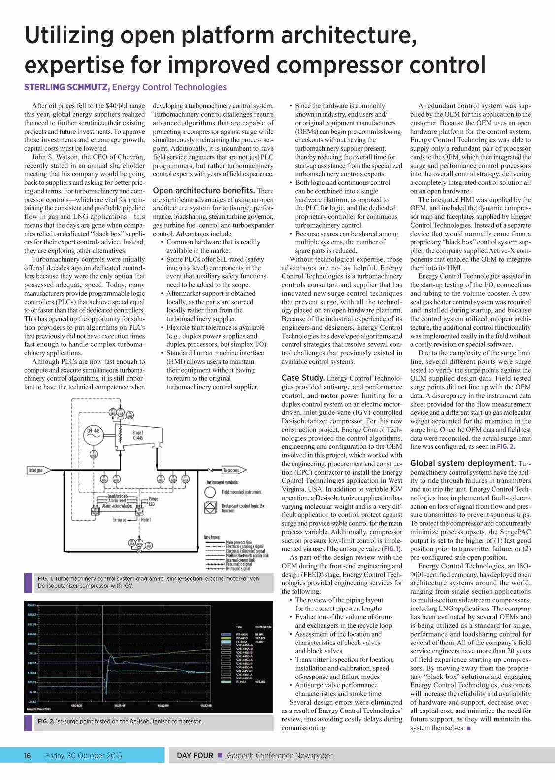
DAY FOUR ■ Gastech Conference Newspaper16 Friday, 30 October 2015
After oil prices fell to the $40/bbl range this year, global energy suppliers realized the need to further scrutinize their existing projects and future investments. To approve those investments and encourage growth, capital costs must be lowered.
John S. Watson, the CEO of Chevron, recently stated in an annual shareholder meeting that his company would be going back to suppliers and asking for better pric-ing and terms. For turbomachinery and com-pressor controls—which are vital for main-taining the consistent and profitable pipeline flow in gas and LNG applications—this means that the days are gone when compa-nies relied on dedicated “black box” suppli-ers for their expert controls advice. Instead, they are exploring other alternatives.
Turbomachinery controls were initially offered decades ago on dedicated control-lers because they were the only option that possessed adequate speed. Today, many manufacturers provide programmable logic controllers (PLCs) that achieve speed equal to or faster than that of dedicated controllers. This has opened up the opportunity for solu-tion providers to put algorithms on PLCs that previously did not have execution times fast enough to handle complex turboma-chinery applications.
Although PLCs are now fast enough to compute and execute simultaneous turboma-chinery control algorithms, it is still impor-tant to have the technical competence when
developing a turbomachinery control system. Turbomachinery control challenges require advanced algorithms that are capable of protecting a compressor against surge while simultaneously maintaining the process set-point. Additionally, it is incumbent to have field service engineers that are not just PLC programmers, but rather turbomachinery control experts with years of field experience.
Open architecture benefits. There are significant advantages of using an open architecture system for antisurge, perfor-mance, loadsharing, steam turbine governor, gas turbine fuel control and turboexpander control. Advantages include:
• Common hardware that is readily available in the market.
• Some PLCs offer SIL-rated (safety integrity level) components in the event that auxiliary safety functions need to be added to the scope.
• Aftermarket support is obtained locally, as the parts are sourced locally rather than from the turbomachinery supplier.
• Flexible fault tolerance is available (e.g., duplex power supplies and duplex processors, but simplex I/O).
• Standard human machine interface (HMI) allows users to maintain their equipment without having to return to the original turbomachinery control supplier.
• Since the hardware is commonly known in industry, end users and/or original equipment manufacturers (OEMs) can begin pre-commissioning checkouts without having the turbomachinery supplier present, thereby reducing the overall time for start-up assistance from the specialized turbomachinery controls experts.
• Both logic and continuous control can be combined into a single hardware platform, as opposed to the PLC for logic, and the dedicated proprietary controller for continuous turbomachinery control.
• Because spares can be shared among multiple systems, the number of spare parts is reduced.
Without technological expertise, those advantages are not as helpful. Energy Control Technologies is a turbomachinery controls consultant and supplier that has innovated new surge control techniques that prevent surge, with all the technol-ogy placed on an open hardware platform. Because of the industrial experience of its engineers and designers, Energy Control Technologies has developed algorithms and control strategies that resolve several con-trol challenges that previously existed in available control systems.
Case Study. Energy Control Technolo-gies provided antisurge and performance control, and motor power limiting for a duplex control system on an electric motor-driven, inlet guide vane (IGV)-controlled De-isobutanizer compressor. For this new construction project, Energy Control Tech-nologies provided the control algorithms, engineering and configuration to the OEM involved in this project, which worked with the engineering, procurement and construc-tion (EPC) contractor to install the Energy Control Technologies application in West Virginia, USA. In addition to variable IGV operation, a De-isobutanizer application has varying molecular weight and is a very dif-ficult application to control, protect against surge and provide stable control for the main process variable. Additionally, compressor suction pressure low-limit control is imple-mented via use of the antisurge valve (FIG. 1).
As part of the design review with the OEM during the front-end engineering and design (FEED) stage, Energy Control Tech-nologies provided engineering services for the following:
• The review of the piping layout for the correct pipe-run lengths
• Evaluation of the volume of drums and exchangers in the recycle loop
• Assessment of the location and characteristics of check valves and block valves
• Transmitter inspection for location, installation and calibration, speed- of-response and failure modes
• Antisurge valve performance characteristics and stroke time.
Several design errors were eliminated as a result of Energy Control Technologies’ review, thus avoiding costly delays during commissioning.
A redundant control system was sup-plied by the OEM for this application to the customer. Because the OEM uses an open hardware platform for the control system, Energy Control Technologies was able to supply only a redundant pair of processor cards to the OEM, which then integrated the surge and performance control processors into the overall control strategy, delivering a completely integrated control solution all on an open hardware.
The integrated HMI was supplied by the OEM, and included the dynamic compres-sor map and faceplates supplied by Energy Control Technologies. Instead of a separate device that would normally come from a proprietary “black box” control system sup-plier, the company supplied Active-X com-ponents that enabled the OEM to integrate them into its HMI.
Energy Control Technologies assisted in the start-up testing of the I/O, connections and tubing to the volume booster. A new seal gas heater control system was required and installed during startup, and because the control system utilized an open archi-tecture, the additional control functionality was implemented easily in the field without a costly revision or special software.
Due to the complexity of the surge limit line, several different points were surge tested to verify the surge points against the OEM-supplied design data. Field-tested surge points did not line up with the OEM data. A discrepancy in the instrument data sheet provided for the flow measurement device and a different start-up gas molecular weight accounted for the mismatch in the surge line. Once the OEM data and field test data were reconciled, the actual surge limit line was configured, as seen in FIG. 2.
Global system deployment. Tur-bomachinery control systems have the abil-ity to ride through failures in transmitters and not trip the unit. Energy Control Tech-nologies has implemented fault-tolerant action on loss of signal from flow and pres-sure transmitters to prevent spurious trips. To protect the compressor and concurrently minimize process upsets, the SurgePAC output is set to the higher of (1) last good position prior to transmitter failure, or (2) pre-configured safe open position.
Energy Control Technologies, an ISO-9001-certified company, has deployed open architecture systems around the world, ranging from single-section applications to multi-section sidestream compressors, including LNG applications. The company has been evaluated by several OEMs and is being utilized as a standard for surge, performance and loadsharing control for several of them. All of the company’s field service engineers have more than 20 years of field experience starting up compres-sors. By moving away from the proprie-tary “black box” solutions and engaging Energy Control Technologies, customers will increase the reliability and availability of hardware and support, decrease over-all capital cost, and minimize the need for future support, as they will maintain the system themselves. ■
Utilizing open platform architecture, expertise for improved compressor controlSTERLING SCHMUTZ, Energy Control Technologies
FIG. 1. Turbomachinery control system diagram for single-section, electric motor-driven De-isobutanizer compressor with IGV.
FIG. 2. 1st-surge point tested on the De-isobutanizer compressor.
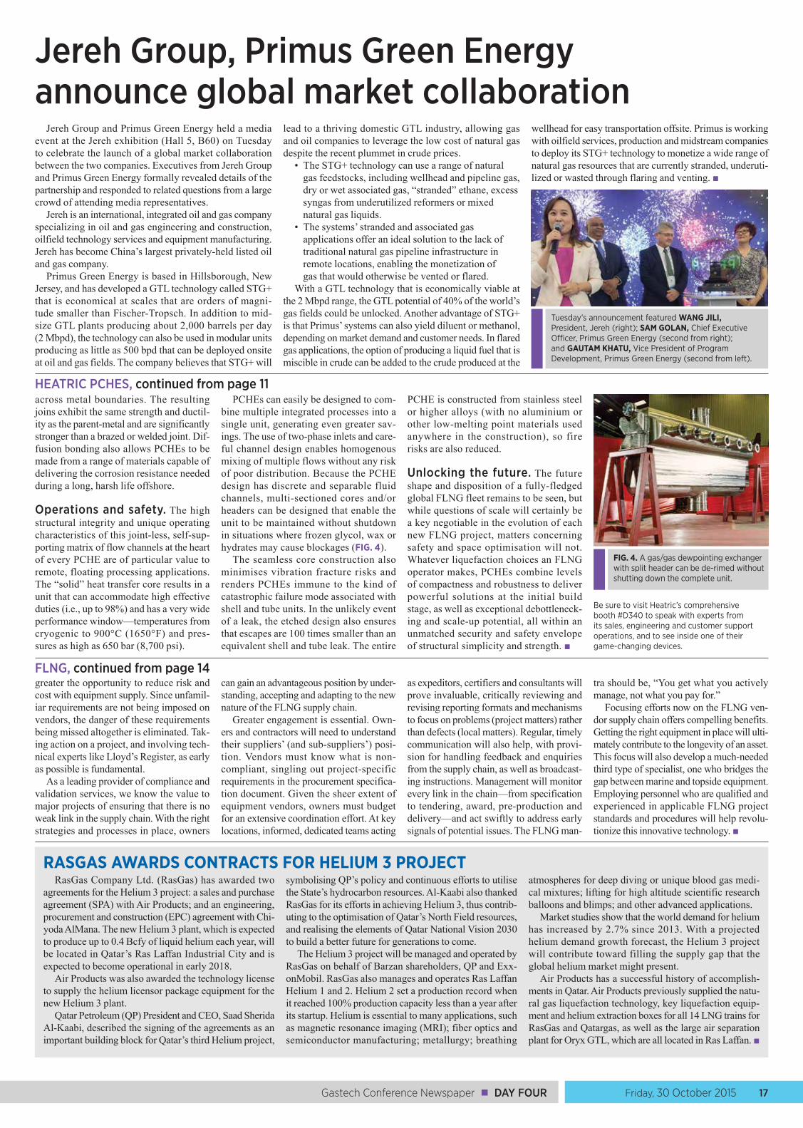
Friday, 30 October 2015 17Gastech Conference Newspaper ■ DAY FOUR
across metal boundaries. The resulting joins exhibit the same strength and ductil-ity as the parent-metal and are significantly stronger than a brazed or welded joint. Dif-fusion bonding also allows PCHEs to be made from a range of materials capable of delivering the corrosion resistance needed during a long, harsh life offshore.
Operations and safety. The high structural integrity and unique operating characteristics of this joint-less, self-sup-porting matrix of flow channels at the heart of every PCHE are of particular value to remote, floating processing applications. The “solid” heat transfer core results in a unit that can accommodate high effective duties (i.e., up to 98%) and has a very wide performance window—temperatures from cryogenic to 900°C (1650°F) and pres-sures as high as 650 bar (8,700 psi).
PCHEs can easily be designed to com-bine multiple integrated processes into a single unit, generating even greater sav-ings. The use of two-phase inlets and care-ful channel design enables homogenous mixing of multiple flows without any risk of poor distribution. Because the PCHE design has discrete and separable fluid channels, multi-sectioned cores and/or headers can be designed that enable the unit to be maintained without shutdown in situations where frozen glycol, wax or hydrates may cause blockages (FIG. 4).
The seamless core construction also minimises vibration fracture risks and renders PCHEs immune to the kind of catastrophic failure mode associated with shell and tube units. In the unlikely event of a leak, the etched design also ensures that escapes are 100 times smaller than an equivalent shell and tube leak. The entire
PCHE is constructed from stainless steel or higher alloys (with no aluminium or other low-melting point materials used anywhere in the construction), so fire risks are also reduced.
Unlocking the future. The future shape and disposition of a fully-fledged global FLNG fleet remains to be seen, but while questions of scale will certainly be a key negotiable in the evolution of each new FLNG project, matters concerning safety and space optimisation will not. Whatever liquefaction choices an FLNG operator makes, PCHEs combine levels of compactness and robustness to deliver powerful solutions at the initial build stage, as well as exceptional debottleneck-ing and scale-up potential, all within an unmatched security and safety envelope of structural simplicity and strength. ■
Be sure to visit Heatric’s comprehensive booth #D340 to speak with experts from its sales, engineering and customer support operations, and to see inside one of their game-changing devices.
HEATRIC PCHES, continued from page 11
FIG. 4. A gas/gas dewpointing exchanger with split header can be de-rimed without shutting down the complete unit.
greater the opportunity to reduce risk and cost with equipment supply. Since unfamil-iar requirements are not being imposed on vendors, the danger of these requirements being missed altogether is eliminated. Tak-ing action on a project, and involving tech-nical experts like Lloyd’s Register, as early as possible is fundamental.
As a leading provider of compliance and validation services, we know the value to major projects of ensuring that there is no weak link in the supply chain. With the right strategies and processes in place, owners
can gain an advantageous position by under-standing, accepting and adapting to the new nature of the FLNG supply chain.
Greater engagement is essential. Own-ers and contractors will need to understand their suppliers’ (and sub-suppliers’) posi-tion. Vendors must know what is non-compliant, singling out project-specific requirements in the procurement specifica-tion document. Given the sheer extent of equipment vendors, owners must budget for an extensive coordination effort. At key locations, informed, dedicated teams acting
as expeditors, certifiers and consultants will prove invaluable, critically reviewing and revising reporting formats and mechanisms to focus on problems (project matters) rather than defects (local matters). Regular, timely communication will also help, with provi-sion for handling feedback and enquiries from the supply chain, as well as broadcast-ing instructions. Management will monitor every link in the chain—from specification to tendering, award, pre-production and delivery—and act swiftly to address early signals of potential issues. The FLNG man-
tra should be, “You get what you actively manage, not what you pay for.”
Focusing efforts now on the FLNG ven-dor supply chain offers compelling benefits. Getting the right equipment in place will ulti-mately contribute to the longevity of an asset. This focus will also develop a much-needed third type of specialist, one who bridges the gap between marine and topside equipment. Employing personnel who are qualified and experienced in applicable FLNG project standards and procedures will help revolu-tionize this innovative technology. ■
FLNG, continued from page 14
Jereh Group, Primus Green Energy announce global market collaboration
Jereh Group and Primus Green Energy held a media event at the Jereh exhibition (Hall 5, B60) on Tuesday to celebrate the launch of a global market collaboration between the two companies. Executives from Jereh Group and Primus Green Energy formally revealed details of the partnership and responded to related questions from a large crowd of attending media representatives.
Jereh is an international, integrated oil and gas company specializing in oil and gas engineering and construction, oilfield technology services and equipment manufacturing. Jereh has become China’s largest privately-held listed oil and gas company.
Primus Green Energy is based in Hillsborough, New Jersey, and has developed a GTL technology called STG+ that is economical at scales that are orders of magni-tude smaller than Fischer-Tropsch. In addition to mid-size GTL plants producing about 2,000 barrels per day (2 Mbpd), the technology can also be used in modular units producing as little as 500 bpd that can be deployed onsite at oil and gas fields. The company believes that STG+ will
lead to a thriving domestic GTL industry, allowing gas and oil companies to leverage the low cost of natural gas despite the recent plummet in crude prices.
• The STG+ technology can use a range of natural gas feedstocks, including wellhead and pipeline gas, dry or wet associated gas, “stranded” ethane, excess syngas from underutilized reformers or mixed natural gas liquids.
• The systems’ stranded and associated gas applications offer an ideal solution to the lack of traditional natural gas pipeline infrastructure in remote locations, enabling the monetization of gas that would otherwise be vented or flared.
With a GTL technology that is economically viable at the 2 Mbpd range, the GTL potential of 40% of the world’s gas fields could be unlocked. Another advantage of STG+ is that Primus’ systems can also yield diluent or methanol, depending on market demand and customer needs. In flared gas applications, the option of producing a liquid fuel that is miscible in crude can be added to the crude produced at the
wellhead for easy transportation offsite. Primus is working with oilfield services, production and midstream companies to deploy its STG+ technology to monetize a wide range of natural gas resources that are currently stranded, underuti-lized or wasted through flaring and venting. ■
Tuesday’s announcement featured WANG JILI, President, Jereh (right); SAM GOLAN, Chief Executive Officer, Primus Green Energy (second from right); and GAUTAM KHATU, Vice President of Program Development, Primus Green Energy (second from left).
RASGAS AWARDS CONTRACTS FOR HELIUM 3 PROJECTRasGas Company Ltd. (RasGas) has awarded two
agreements for the Helium 3 project: a sales and purchase agreement (SPA) with Air Products; and an engineering, procurement and construction (EPC) agreement with Chi-yoda AlMana. The new Helium 3 plant, which is expected to produce up to 0.4 Bcfy of liquid helium each year, will be located in Qatar’s Ras Laffan Industrial City and is expected to become operational in early 2018.
Air Products was also awarded the technology license to supply the helium licensor package equipment for the new Helium 3 plant.
Qatar Petroleum (QP) President and CEO, Saad Sherida Al-Kaabi, described the signing of the agreements as an important building block for Qatar’s third Helium project,
symbolising QP’s policy and continuous efforts to utilise the State’s hydrocarbon resources. Al-Kaabi also thanked RasGas for its efforts in achieving Helium 3, thus contrib-uting to the optimisation of Qatar’s North Field resources, and realising the elements of Qatar National Vision 2030 to build a better future for generations to come.
The Helium 3 project will be managed and operated by RasGas on behalf of Barzan shareholders, QP and Exx-onMobil. RasGas also manages and operates Ras Laffan Helium 1 and 2. Helium 2 set a production record when it reached 100% production capacity less than a year after its startup. Helium is essential to many applications, such as magnetic resonance imaging (MRI); fiber optics and semiconductor manufacturing; metallurgy; breathing
atmospheres for deep diving or unique blood gas medi-cal mixtures; lifting for high altitude scientific research balloons and blimps; and other advanced applications.
Market studies show that the world demand for helium has increased by 2.7% since 2013. With a projected helium demand growth forecast, the Helium 3 project will contribute toward filling the supply gap that the global helium market might present.
Air Products has a successful history of accomplish-ments in Qatar. Air Products previously supplied the natu-ral gas liquefaction technology, key liquefaction equip-ment and helium extraction boxes for all 14 LNG trains for RasGas and Qatargas, as well as the large air separation plant for Oryx GTL, which are all located in Ras Laffan. ■
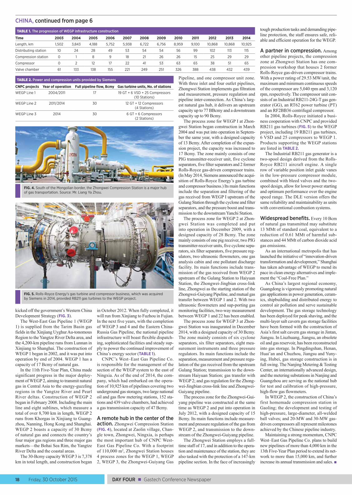
DAY FOUR ■ Gastech Conference Newspaper18 Friday, 30 October 2015
kicked off the government’s Western China Development Strategy (FIG. 3).
The West-East Gas Pipeline 1 (WEGP 1) is supplied from the Tarim Basin gas fields in the Xinjiang Uyghur Au-tonomous Region to the Yangtze River Delta area, and the 4,200-km pipeline runs from Lunnan in Xinjiang to Shanghai. The construction of WEGP 1 began in 2002, and it was put into operation by end of 2004. WEGP 1 has a capacity of 17 Bcmy of natural gas.
In the 11th Five-Year Plan, China made significant progress in the major deploy-ment of WEGP 2, aiming to transmit natural gas in Central Asia to the energy-guzzling regions in the Yangtze River and Pearl River deltas. Construction of WEGP 2 began in February 2008. Including the main line and eight sublines, which measure a total of over 8,700 km in length, WEGP 2 runs from Khorgas in Xinjiang to Guang-zhou, Nanning, Hong Kong and Shanghai. WEGP 2 boasts a capacity of 30 Bcmy of natural gas and connects the country’s four major gas regions and three major gas markets—the Bohai Sea Rim, the Yangtze River Delta and the coastal areas.
The 30-Bcmy capacity WEGP 3 is 7,378 km in total length, and construction began
in October 2012. When fully completed, it will run from Xinjiang to Fuzhou in Fujian. In the next five years, with the completion of WEGP 3 and 4 and the Eastern China-Russia Gas Pipeline, the national pipeline infrastructure will boast flexible dispatch-ing, sophisticated facilities and steady sup-ply to power the continued improvement of China’s energy sector (TABLE 1).
CNPC’s West–East Gas Pipeline Co. is responsible for the management of the section of the WEGP system to the east of Ningxia. As of the end of 2014, the com-pany, which had embarked on the opera-tion of 10,925 km of pipelines covering two underground gas storages, two large national oil and gas flow metering stations, 152 sta-tions and 439 valve chambers, had achieved a gas transmission capacity of 47 Bcmy.
A remote hub in the center of the action. Zhongwei Compression Station (FIG. 4), located at Zaolin village, Chan-gle town, Zhongwei, Ningxia, is perhaps the most important hub of CNPC West-East Gas Pipeline Co. With a footprint of 110,000 m2, Zhongwei Station houses 4 process zones for the WEGP 1, WEGP 2, WEGP 3, the Zhongwei-Guiyang Gas
Pipeline, and one compressor unit zone. With three inlet and four outlet pipelines, Zhongwei Station implements gas filtration and measurement, pressure regulation and pipeline inter-connection. As China’s larg-est natural gas hub, it delivers an upstream capacity up to 77 BBcmy and a downstream capacity up to 90 Bcmy.
The process zone for WEGP I at Zhon-gwei Station began construction in March 2004 and was put into operation in Septem-ber the same year, with a designed capacity of 13 Bcmy. After completion of the expan-sion project, the capacity was increased to 17 Bcmy. The zone mainly consists of one PIG transmitter-receiver unit, five cyclone separators, five filter separators and 2 former Rolls-Royce gas-driven compressor trains. (In May 2014, Siemens announced the acqui-sition of Rolls-Royce Energy’s gas turbine and compressor business.) Its main functions include the separation and filtering of the gas received from WEGP I upstream of the Gulang Station through the cyclone and filter separators, and the pressure boost and trans-mission to the downstream Yanchi Station.
The process zone for WEGP 2 at Zhon-gwei Station was completed and put into operation in December 2009, with a designed capacity of 28 Bcmy. The zone mainly consists of one pig receiver, two PIG transmitter-receiver units, five cyclone sepa-rators, six filter separators, five pressure reg-ulators, two ultrasonic flowmeters, one gas analysis cabin and one pollutant discharge facility. Its main functions include trans-mission of the gas received from WEGP 2 upstream of the Gulang Station to Haiyuan Station, the Zhongwei-Jingbian cross-link line, Zhongwei as the starting station of the Zhongwei-Guiyang Pipeline, and mutual gas transfer between WEGP 1 and 2. With two ultrasonic flowmeters and sup-porting gas monitoring facilities, two-way measurement between WEGP 1 and 22 has been enabled.
The process zone for WEGP 3 at Zhon-gwei Station was inaugurated in December 2014, with a designed capacity of 30 Bcmy. The zone mainly consists of six cyclone separators, six filter separators, eight mea-surement instruments and three pressure regulators. Its main functions include the separation, measurement and pressure regu-lation of the gas received from the upstream Gulang Station; transmission to the down-stream Haiyuan Station; gas transfer with WEGP 2; and gas regulation for the Zhong-wei-Jingbian cross-link line and Zhongwei-Guiyang pipeline.
The process zone for the Zhongwei-Gui-yang pipeline was constructed at the same time as WEGP 2 and put into operation in July 2012, with a designed capacity of 15 Bcmy. Its main functions include measure-ment and pressure regulation of the gas from WEGP 2, and transmission to the down-stream of the Zhongwei-Guiyang pipeline.
The Zhongwei Station employs a full-time staff of 17, and in addition to the opera-tion and maintenance of the station, they are also tasked with the protection of a 147-km pipeline section. In the face of increasingly
tough production tasks and demanding pipe-line protection, the staff ensures safe, reli-able and efficient operation for the WEGP.
A partner in compression. Among other pipeline projects, the compression zone at Zhongwei Station has one com-pression workshop that houses 2 former Rolls-Royce gas-driven compressor trains. With a power rating of 29.53 MW/unit, the maximum and minimum continuous speeds of the compressor are 5,040 rpm and 3,120 rpm, respectively. The compressor unit con-sists of an Industrial RB211-24G-T gas gen-erator (GG), an RT62 power turbine (PT) and an RF2BB36 centrifugal compressor.
In 2004, Rolls-Royce initiated a busi-ness cooperation with CNPC and provided RB211 gas turbines (FIG. 5) to the WEGP project, including 19 RB211 gas turbines, 6 VSD and 25 compressors to WEGP 1. Products supporting the WEGP stations are listed in TABLE 2.
The Industrial RB211 gas generator is a two-spool design derived from the Rolls-Royce RB211 aircraft engine. A single row of variable position inlet guide vanes in the low-pressure compressor module, combined with bleed valves and the two-spool design, allow for lower power starting and optimum performance over the engine speed range. The DLE version offers the same reliability and maintainability as units with conventional combustion systems.
Widespread benefits. Every 10 Bcm of natural gas transmitted may substitute 13 MMt of standard coal, equivalent to a reduction of 0.61 MMt of harmful sub-stances and 44 MMt of carbon dioxide acid gas emissions.
As an international metropolis that has launched the initiative of “innovation-driven transformation and development,” Shanghai has taken advantage of WEGP to mend its pace in clean energy alternatives and imple-ment the “Coal-Free Plan.”
As China’s largest regional economy, Guangdong is vigorously promoting natural gas applications in power generation, ceram-ics, shipbuilding and distributed energy to control air pollution and serve sustainable development. The gas storage technology has been deployed for peak shaving, and the multi-layer salt cavern gas storage facilities have been formed with the construction of Asia’s first salt cavern gas storage in Jintan, Jiangsu. In Liuzhuang, Jiangsu, an obsolete oil and gas reservoir, has been reconstructed into gas storage. In Pingdingshan, Henan, Huai’an and Chuzhou, Jiangsu and Yuny-ing, Hubei, gas storage construction is in full swing. The Nanjing Metering & Testing Center, an internationally advanced design, and the metering substations in Nanjing and Guangzhou are serving as the national hub for test and calibration of high-pressure, high-flow gas flowmeters.
In WEGP 2, the construction of China’s first homemade compression station in Gaoling; the development and testing of high-pressure, large-diameter, all-welded ball valves; and 20-MW and 30-MW gas-driven compressors all represent milestones achieved by the Chinese pipeline industry.
Maintaining a strong momentum, CNPC West–East Gas Pipeline Co. plans to build new pipelines of more than 4,000 km in the 13th Five-Year Plan period to extend its net-work to more than 15,000 km, and further increase its annual transmission and sales. ■
FIG. 4. South of the Mongolian border, the Zhongwei Compression Station is a major hub of gas transportation. Source: Mr. Liang Ya Zhou.
FIG. 5. Rolls-Royce Energy’s gas turbine and compressor business, which was acquired by Siemens in 2014, provided RB211 gas turbines to the WEGP project.
TABLE 1. The progression of WEGP infrastructure construction
Time 2003 2004 2005 2006 2007 2008 2009 2010 2011 2012 2013 2014
Length, km 1,502 3,843 4,188 5,752 5,938 6,722 6,756 8,959 9,100 10,868 10,868 10,925
Distributing station 10 24 28 49 53 54 54 56 99 102 113 115
Compression station 0 1 8 9 18 21 26 26 15 25 29 29
Compressor 0 2 12 17 22 41 53 63 65 38 51 65
Valve chamber 61 133 138 155 221 249 251 326 388 438 432 439
TABLE 2. Power and compression units provided by Siemens
CNPC projects Year of operation Full pipeline flow, Bcmy Gas turbine units, No. of stations
WEGP Line 1 2004/2011 17 19 GT + 6 VSD + 25 Compressors (10 Stations)
WEGP Line 2 2011/2014 30 12 GT + 12 Compressors (4 Stations)
WEGP Line 3 2014 30 6 GT + 6 Compressors (2 Stations)
CHINA, continued from page 6
Friday, 30 October 2015 19Gastech Conference Newspaper ■ DAY FOUR
Scenes from Gastech
In front of TOTAL’S stand, a television crew interviews attendees about Gastech’s events and current natural gas issues.
Exhibitors and customers enjoy a light moment at EXXONMOBIL’S stand.
An exhibitor explains his firm’s business line to interested attendees.
Location, location, location—foot traffic remained heavy around KBR’S stand in Hall 4.
Gastech Co-Chairman PAUL SULLIVAN trades project stories with industry friends at the WORLEYPARSONS booth.
Engineers compared notes at the neighboring SAMSUNG and SHELL stands.
SAIPEM’S stand is filled with substantial information on offshore and onshore construction and drilling projects.
Representing Chart Ferox a.s, VACLAV CHRZ describes how to match LNG fueling stations to vehicle fleets during a CoTEs session.
Gastech attendees received vital information on gas trends during a Commercial Stream session.
Delfin LNG Founder and CEO FREDERICK JONES explains to attendees why he thinks the US is the perfect place to revolutionize LNG trade.
HOSTED BY:
OFFICIAL KNOWLEDGE PARTNER ORGANISED BY OFFICIAL KNOWLEDGE PARTNER ORGANISED BY
MOREMEETINGS & NETWORKING
MOREEXHIBITION SPACE
Connecting, informing and advancing the world’s gas and LNG value chain
MORECONFERENCEDELEGATES
MOREBUSINESS
SECURE YOUR PARTICIPATION OR FIND OUT MORE ABOUT GASTECH 2017!
[email protected]+65 6422 1475 (Singapore)+44 203 772 6091 (London)+81 3 6455 4175 (Japan)
www.gastechevent.com
GT17 Advert for show daily v1.indd 1 14/10/2015 11:03