Embed Size (px)
Citation preview

Gasket & FastenerHandbookA Technical Guide To Gasketing & Bolted Flanges

w w w . l a m o n s . c o m
About LamonsLamons is one of the largest gasket and bolt suppliers in the world, committed to quality and local service. We have 6 manufacturing and 21 sales and services branches positioned all around the world combined with many licensees and distributors. We are strategically located to provide customers with the widest selection of gasket materials and fastener stock ready for immediate delivery. Lamons’ various locations feature leading technology and state of the art manufacturing facilities capable of producing engineered products to custom specifications serving the refining, chemical, power generation, offshore, subsea, petrochemical (upstream and downstream), and pulp and paper industries, among others.

50Sealing Global - Servicing Local
Section Two: Semi-Metallic Gaskets
Semi-Metallic gaskets are designed to feature soft, pliable sealing materials - which enhance the tightness of the assembly with lower overall load requirements when compared to full metallic gaskets. They are most popular due to this confi guration, and are available in a wide variety of styles and sizes. They can typically be fabricated of any metal which is available in thin strip or sheet, and which can be welded. Therefore, they can be used against virtually any corrosive medium dependent upon the choice of the metal and fi ller/facing material. Additionally, they can be used over the complete temperature range from cryogenic to approximately 2000ºF (1093ºC). Semi-metallic gaskets can generally be used in pressures ranging from vacuum to those seen in ASME B16.5 standard 2500 pressure class fl ange ratings. They are resilient and, as a consequence, can compensate somewhat for fl ange movement that may occur due to temperature gradients, variations of pressure and vibration.
Lamons offers the following fi ller / facing materials for semi-metallic gaskets:
Temperature Range
PTFE Cryogenic to 500°F (260ºC)
Flexible Graphite Cryogenic to 850°F (454ºC)
Oxidati on Resistant Grade Flexible Graphite Cryogenic to 975°F (524ºC)
HTG (High Temperature Gasket) Cryogenic to 1500°F (816ºC)
Mica Cryogenic to 1832°F (1000ºC)
Ceramic Cryogenic to 2000°F (1093ºC)
51Sealing Global - Servicing Local
Lamons CorruKammTM Product Family
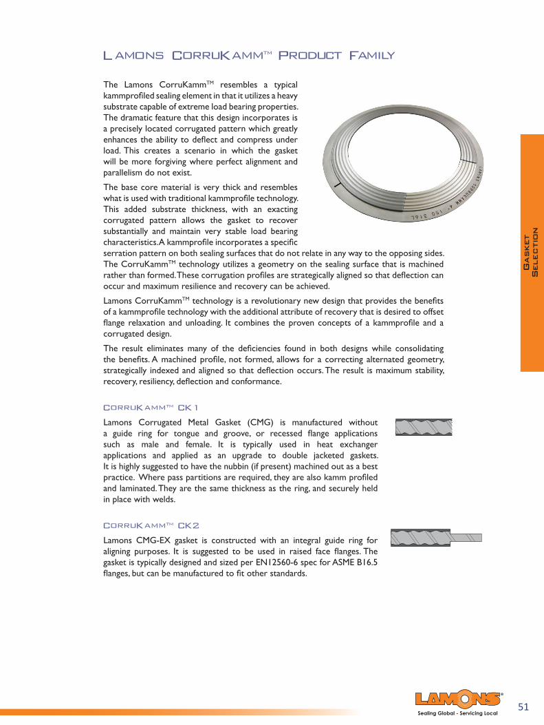
The Lamons CorruKammTM resembles a typical kammprofiled sealing element in that it utilizes a heavy substrate capable of extreme load bearing properties. The dramatic feature that this design incorporates is a precisely located corrugated pattern which greatly enhances the ability to deflect and compress under load. This creates a scenario in which the gasket will be more forgiving where perfect alignment and parallelism do not exist.
The base core material is very thick and resembles what is used with traditional kammprofile technology. This added substrate thickness, with an exacting corrugated pattern allows the gasket to recover substantially and maintain very stable load bearing characteristics. A kammprofile incorporates a specific serration pattern on both sealing surfaces that do not relate in any way to the opposing sides. The CorruKammTM technology utilizes a geometry on the sealing surface that is machined rather than formed. These corrugation profiles are strategically aligned so that deflection can occur and maximum resilience and recovery can be achieved.
Lamons CorruKammTM technology is a revolutionary new design that provides the benefits of a kammprofile technology with the additional attribute of recovery that is desired to offset flange relaxation and unloading. It combines the proven concepts of a kammprofile and a corrugated design.
The result eliminates many of the deficiencies found in both designs while consolidating the benefits. A machined profile, not formed, allows for a correcting alternated geometry, strategically indexed and aligned so that deflection occurs. The result is maximum stability, recovery, resiliency, deflection and conformance.
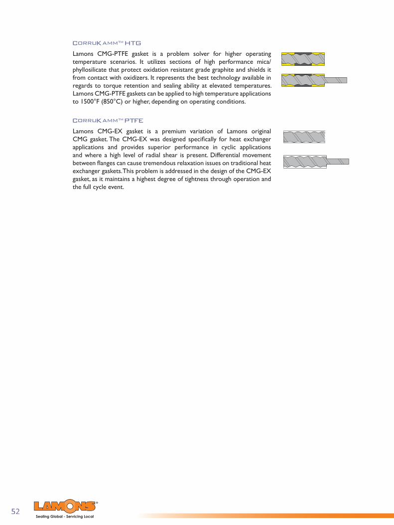
CorruKammTM CK1
Lamons Corrugated Metal Gasket (CMG) is manufactured without a guide ring for tongue and groove, or recessed flange applications such as male and female. It is typically used in heat exchanger applications and applied as an upgrade to double jacketed gaskets. It is highly suggested to have the nubbin (if present) machined out as a best practice. Where pass partitions are required, they are also kamm profiled and laminated. They are the same thickness as the ring, and securely held in place with welds.
CorruKammTM CK2
Lamons CMG-EX gasket is constructed with an integral guide ring for aligning purposes. It is suggested to be used in raised face flanges. The gasket is typically designed and sized per EN12560-6 spec for ASME B16.5 flanges, but can be manufactured to fit other standards.
52Sealing Global - Servicing Local
CorruKammTM HTG
Lamons CMG-PTFE gasket is a problem solver for higher operating temperature scenarios. It utilizes sections of high performance mica/phyllosilicate that protect oxidation resistant grade graphite and shields it from contact with oxidizers. It represents the best technology available in regards to torque retention and sealing ability at elevated temperatures. Lamons CMG-PTFE gaskets can be applied to high temperature applications to 1500°F (850°C) or higher, depending on operating conditions.
CorruKammTM PTFE
Lamons CMG-EX gasket is a premium variation of Lamons original CMG gasket. The CMG-EX was designed specifi cally for heat exchanger applications and provides superior performance in cyclic applications and where a high level of radial shear is present. Differential movement between fl anges can cause tremendous relaxation issues on traditional heat exchanger gaskets. This problem is addressed in the design of the CMG-EX gasket, as it maintains a highest degree of tightness through operation and the full cycle event.

53Sealing Global - Servicing Local
Lamons Kammpro® GasketProduct Family
Lamons Kammpro gaskets are recognized as a problem solver for heat exchangers, large vessels, and equipment that experience excessive movement due to thermal expansion. The Kammpro provides one of the tightest seals combined with superior load bearing characteristics. Kammpro gaskets consist of a metal sealing core with or without a guide ring. The sealing core is a solid metal gasket with concentric serrations on both sealing surfaces and faced with a soft material such as flexible graphite, EPTFE, or a Lamons HTG configuration depending on operating conditions. It is the preferred design when needing improved performance at low seating stresses. The simultaneous actions of a high compressibility facing material on the outside of the grooved metal in combination with limited penetration of the tips of the solid metal core enhance the interaction of the two materials. This allows the components to perform individually to their optimum capabilities. Kammpro gaskets are manufactured in different materials and non-circular shapes with extreme accuracy. They can also be custom engineered to fit various applications. The suggested flange surface finish for Kammpro gaskets is 125-250 AARH.
Kammpro LP 1 is manufactured without a guide ring for tongue and groove, or recessed flange applications such as male and female. It is typically used in heat exchanger applications and applied as an upgrade to double jacketed gaskets. It is highly suggested to have the nubbin (if present) machined out as a best practice. Where pass partitions are required, they are also kamm profiled and laminated. They are the same thickness as the ring, and securely held in place with welds.
Kammpro LP2 is constructed with an integral guide ring for aligning purposes. It is suggested to be used in raised face flanges. The gasket is typically designed and sized per EN12560-6 spec for ASME B16.5 flanges, but can be manufactured to fit other standards.
Kammpro LP3 utilizes a loose fit guide ring. This popular design is preferred for nominal pipe size and pressure class raised face flanges and is used in equipment with excessive radial shear characteristics, thermal cycling, and expansions. The gasket is typically designed and sized per EN12560-6 spec for ASME B16.5 flanges, but can be manufactured to fit other standards.
Kammpro-HTG is a problem solver for higher operating temperature scenarios. It utilizes sections of high performance mica/phyllosilicate that protect oxidation resistant grade graphite and shields it from contact with oxidizers. Lamons Kammpro-HTG represents the best technology available in regards to torque retention and sealing ability at elevated temperatures. Lamons Kammpro HTG gaskets can be applied to high temperature applications to 1500°F (850°C) or higher, depending on operating conditions.
54Sealing Global - Servicing Local
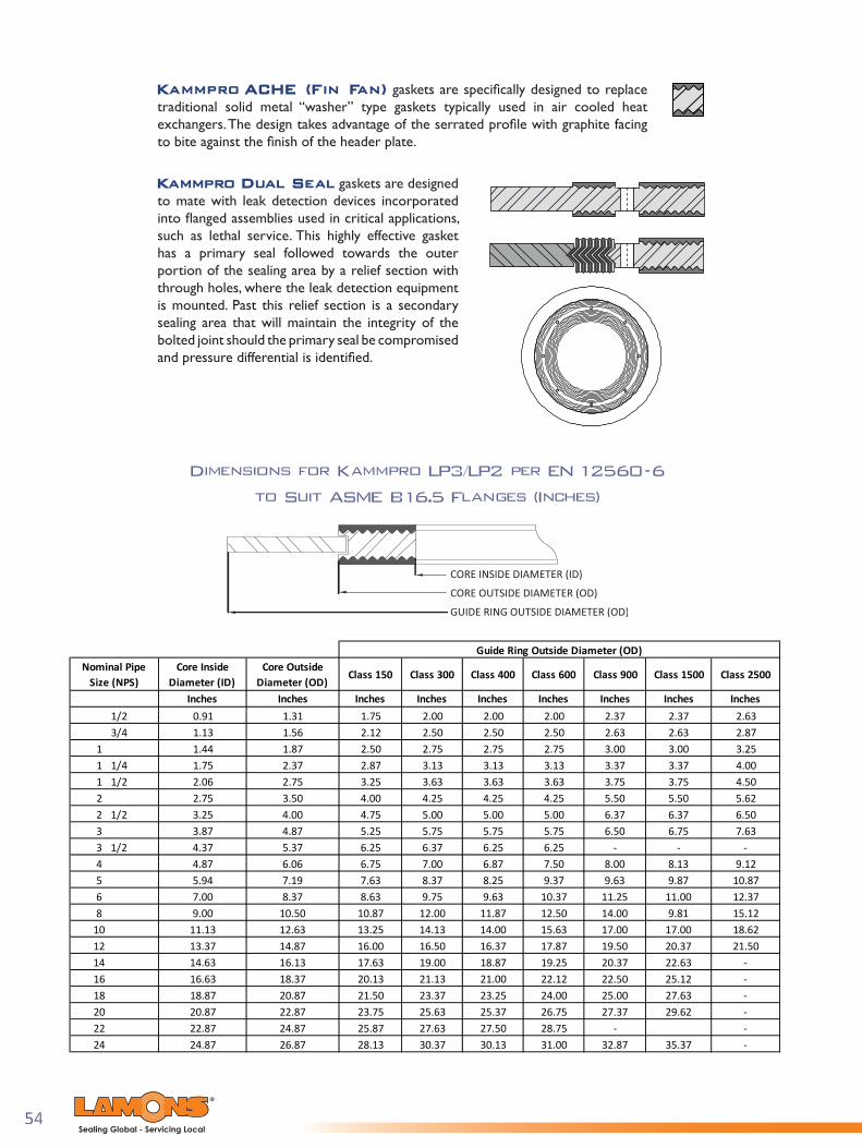
Kammpro ACHE (Fin Fan) gaskets are specifi cally designed to replace traditional solid metal “washer” type gaskets typically used in air cooled heat exchangers. The design takes advantage of the serrated profi le with graphite facing to bite against the fi nish of the header plate.
Kammpro Dual Seal gaskets are designed to mate with leak detection devices incorporated into fl anged assemblies used in critical applications, such as lethal service. This highly effective gasket has a primary seal followed towards the outer portion of the sealing area by a relief section with through holes, where the leak detection equipment is mounted. Past this relief section is a secondary sealing area that will maintain the integrity of the bolted joint should the primary seal be compromised and pressure differential is identifi ed.
Dimensions for Kammpro LP3/LP2 per EN 12560-6
to Suit ASME B16.5 Flanges (Inches)
Nominal Pipe Size (NPS)
Core Inside Diameter (ID)
Core Outside Diameter (OD)
Class 150 Class 300 Class 400 Class 600 Class 900 Class 1500 Class 2500
Inches Inches Inches Inches Inches Inches Inches Inches Inches1/2 0.91 1.31 1.75 2.00 2.00 2.00 2.37 2.37 2.633/4 1.13 1.56 2.12 2.50 2.50 2.50 2.63 2.63 2.87
1 1.44 1.87 2.50 2.75 2.75 2.75 3.00 3.00 3.251 1/4 1.75 2.37 2.87 3.13 3.13 3.13 3.37 3.37 4.001 1/2 2.06 2.75 3.25 3.63 3.63 3.63 3.75 3.75 4.502 2.75 3.50 4.00 4.25 4.25 4.25 5.50 5.50 5.622 1/2 3.25 4.00 4.75 5.00 5.00 5.00 6.37 6.37 6.503 3.87 4.87 5.25 5.75 5.75 5.75 6.50 6.75 7.633 1/2 4.37 5.37 6.25 6.37 6.25 6.25 - - -4 4.87 6.06 6.75 7.00 6.87 7.50 8.00 8.13 9.125 5.94 7.19 7.63 8.37 8.25 9.37 9.63 9.87 10.876 7.00 8.37 8.63 9.75 9.63 10.37 11.25 11.00 12.378 9.00 10.50 10.87 12.00 11.87 12.50 14.00 9.81 15.12
10 11.13 12.63 13.25 14.13 14.00 15.63 17.00 17.00 18.6212 13.37 14.87 16.00 16.50 16.37 17.87 19.50 20.37 21.5014 14.63 16.13 17.63 19.00 18.87 19.25 20.37 22.63 -16 16.63 18.37 20.13 21.13 21.00 22.12 22.50 25.12 -18 18.87 20.87 21.50 23.37 23.25 24.00 25.00 27.63 -20 20.87 22.87 23.75 25.63 25.37 26.75 27.37 29.62 -22 22.87 24.87 25.87 27.63 27.50 28.75 - -24 24.87 26.87 28.13 30.37 30.13 31.00 32.87 35.37 -
Guide Ring Outside Diameter (OD)

55Sealing Global - Servicing Local
Dimensions for Kammpro LP3/LP2 per EN 12560-6
to Suit ASME B16.5 Flanges (Millimeters)
Nominal Pipe Size (NPS)
Core Inside Diameter (ID)
Core Outside Diameter (OD)
Class 150 Class 300 Class 400 Class 600 Class 900 Class 1500 Class 2500
mm mm mm mm mm mm mm mm mm1/2 23.0 33.3 44.4 50.8 50.8 50.8 60.3 60.3 66.73/4 28.6 39.7 53.9 63.5 63.5 63.5 66.7 66.7 73.0
1 36.5 47.6 63.5 69.8 69.8 69.8 76.2 76.2 82.51 1/4 44.4 60.3 73.0 79.4 79.4 79.4 85.7 85.7 101.61 1/2 52.4 69.8 82.5 92.1 92.1 92.1 95.2 95.2 114.32 69.8 88.9 101.6 108.0 108.0 108.0 139.7 139.7 142.82 1/2 82.5 101.6 120.6 127.0 127.0 127.0 161.9 161.9 165.13 98.4 123.8 133.4 146.1 146.1 146.1 165.1 171.5 193.73 1/2 111.1 136.5 158.8 161.9 158.7 158.7 - - -4 123.8 154.0 171.5 177.8 174.6 190.5 203.2 206.4 231.75 150.8 182.6 193.7 212.7 209.5 238.1 244.5 250.8 276.26 177.8 212.7 219.1 247.7 244.5 263.5 285.8 279.4 314.38 228.6 266.7 276.2 304.8 301.6 317.5 355.6 249.3 384.1
10 282.6 320.7 336.5 358.8 355.6 396.9 431.8 431.8 473.012 339.7 377.8 406.4 419.1 415.9 454.0 495.3 517.5 546.114 371.5 409.6 447.7 482.6 479.4 488.9 517.5 574.7 -16 422.3 466.7 511.2 536.6 533.4 561.9 571.5 638.1 -18 479.4 530.2 546.1 593.7 590.5 609.6 635.0 701.7 -20 530.2 581.0 603.2 650.9 644.5 679.5 695.3 752.4 -22 581.0 631.8 657.2 701.7 698.5 730.3 - - -24 631.8 682.6 714.4 771.5 765.2 787.4 835.0 898.5 -
Guide Ring Outside Diameter (OD)

56Sealing Global - Servicing Local
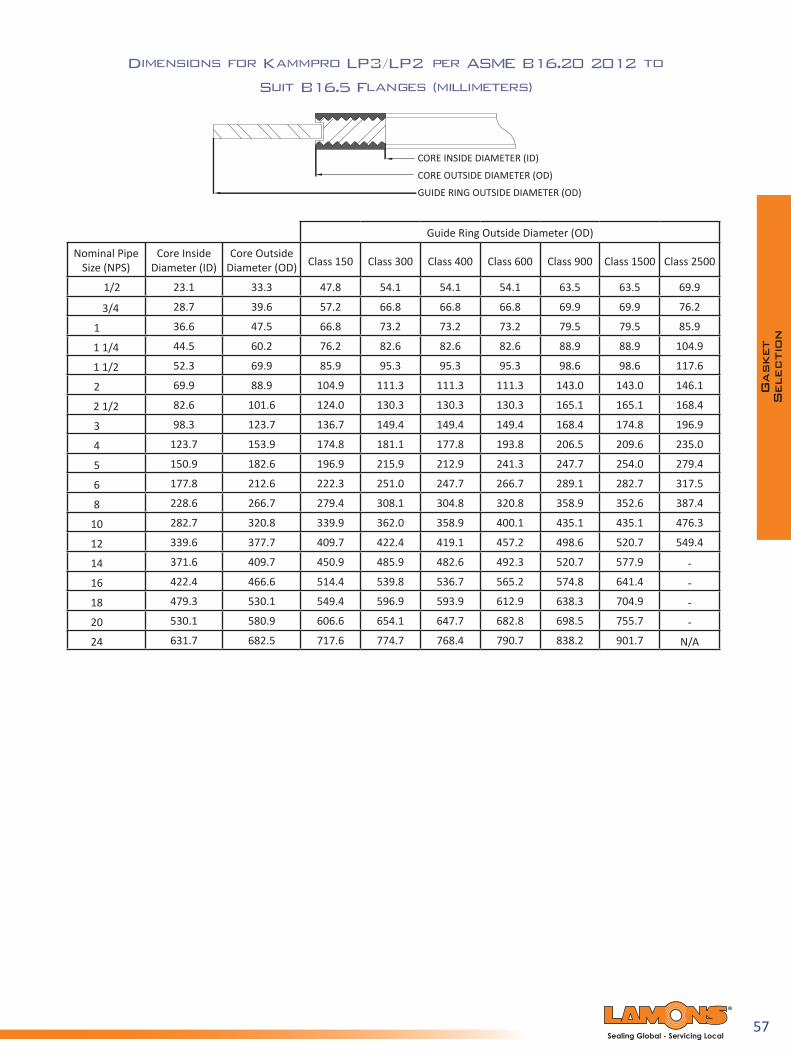
Dimensions for Kammpro LP3/LP2 per ASME B16.20 2012 to
Suit B16.5 Flanges (Inches)
Guide Ring Outside Diameter (OD)
Nominal Pipe Size (NPS)
Core Inside Diameter (ID)
Core Outside Diameter (OD) Class 150 Class 300 Class 400 Class 600 Class 900 Class 1500 Class 2500
1/2 0.91 1.31 1.88 2.13 2.13 2.13 2.50 2.50 2.75
3/4 1.13 1.56 2.25 2.63 2.63 2.63 2.75 2.75 3.00
1 1.44 1.87 2.63 2.88 2.88 2.88 3.13 3.13 3.38
1 1/4 1.75 2.37 3.00 3.25 3.25 3.25 3.50 3.50 4.13
1 1/2 2.06 2.75 3.38 3.75 3.75 3.75 3.88 3.88 4.63
2 2.75 3.50 4.13 4.38 4.38 4.38 5.63 5.63 5.75
2 1/2 3.25 4.00 4.88 5.13 5.13 5.13 6.50 6.50 6.63
3 3.87 4.87 5.38 5.88 5.88 5.88 6.63 6.88 7.75
4 4.87 6.06 6.88 7.13 7.00 7.63 8.13 8.25 9.25
5 5.94 7.19 7.75 8.50 8.38 9.50 9.75 10.00 11.00
6 7.00 8.37 8.75 9.88 9.75 10.50 11.38 11.13 12.50
8 9.00 10.50 11.00 12.13 12.00 12.63 14.13 13.88 15.25
10 11.13 12.63 13.38 14.25 14.13 15.75 17.13 17.13 18.75
12 13.37 14.87 16.13 16.63 16.50 18.00 19.63 20.50 21.63
14 14.63 16.13 17.75 19.31 19.00 19.38 20.50 22.75 -
16 16.63 18.37 20.25 21.25 21.13 22.25 22.63 25.25 -
18 18.87 20.87 21.63 23.50 23.38 24.13 25.13 27.75 -
20 20.87 22.87 23.88 25.75 25.50 26.88 27.50 29.75 -
24 24.87 26.87 28.25 30.50 30.25 31.13 33.00 35.50 N/A
57Sealing Global - Servicing Local
Dimensions for Kammpro LP3/LP2 per ASME B16.20 2012 to
Suit B16.5 Flanges (millimeters)
Guide Ring Outside Diameter (OD)
Nominal Pipe Size (NPS)
Core Inside Diameter (ID)
Core Outside Diameter (OD) Class 150 Class 300 Class 400 Class 600 Class 900 Class 1500 Class 2500
1/2 23.1 33.3 47.8 54.1 54.1 54.1 63.5 63.5 69.9
3/4 28.7 39.6 57.2 66.8 66.8 66.8 69.9 69.9 76.2
1 36.6 47.5 66.8 73.2 73.2 73.2 79.5 79.5 85.9
1 1/4 44.5 60.2 76.2 82.6 82.6 82.6 88.9 88.9 104.9
1 1/2 52.3 69.9 85.9 95.3 95.3 95.3 98.6 98.6 117.6
2 69.9 88.9 104.9 111.3 111.3 111.3 143.0 143.0 146.1
2 1/2 82.6 101.6 124.0 130.3 130.3 130.3 165.1 165.1 168.4
3 98.3 123.7 136.7 149.4 149.4 149.4 168.4 174.8 196.9
4 123.7 153.9 174.8 181.1 177.8 193.8 206.5 209.6 235.0
5 150.9 182.6 196.9 215.9 212.9 241.3 247.7 254.0 279.4
6 177.8 212.6 222.3 251.0 247.7 266.7 289.1 282.7 317.5
8 228.6 266.7 279.4 308.1 304.8 320.8 358.9 352.6 387.4
10 282.7 320.8 339.9 362.0 358.9 400.1 435.1 435.1 476.3
12 339.6 377.7 409.7 422.4 419.1 457.2 498.6 520.7 549.4
14 371.6 409.7 450.9 485.9 482.6 492.3 520.7 577.9 -
16 422.4 466.6 514.4 539.8 536.7 565.2 574.8 641.4 -
18 479.3 530.1 549.4 596.9 593.9 612.9 638.3 704.9 -
20 530.1 580.9 606.6 654.1 647.7 682.8 698.5 755.7 -
24 631.7 682.5 717.6 774.7 768.4 790.7 838.2 901.7 N/A

58Sealing Global - Servicing Local
Dimensions for Kammpro LP3/LP2 per ASME B16.47 Series A to Suit B16.47 Series A (Inches)
Centering Ring
Centering Ring
Centering Ring
Centering Ring
Centering Ring
NPSInside
DiameterOutside
DiameterOutside
DiameterInside
DiameterOutside
DiameterOutside
DiameterInside
DiameterOutside
DiameterOutside
DiameterInside
DiameterOutside
DiameterOutside
DiameterInside
DiameterOutside
DiameterOutside
Diameter
26 26.50 27.75 30.50 27.00 29.00 32.88 27.00 29.00 32.75 27.00 29.00 34.13 27.00 29.00 34.75
28 28.50 29.75 32.75 29.00 31.00 35.38 29.00 31.00 35.13 29.00 31.00 36.00 29.00 31.00 37.25
30 30.50 31.75 34.75 31.25 33.25 37.50 31.25 33.25 37.25 31.25 33.25 38.25 31.25 33.25 39.75
32 32.50 33.88 37.00 33.50 35.50 39.63 33.50 35.50 39.50 33.50 35.50 40.25 33.50 35.50 42.25
34 34.50 35.88 39.00 35.50 37.50 41.63 35.50 37.50 41.50 35.50 37.50 42.25 35.50 37.50 44.75
36 36.50 38.13 41.25 37.63 39.63 44.00 37.63 39.63 44.00 37.63 39.63 44.50 37.75 39.75 47.25
38 38.50 40.13 43.75 38.50 40.00 41.50 38.25 40.25 42.25 39.00 41.00 43.50 40.75 42.75 47.25
40 40.50 42.13 45.75 40.25 42.13 43.88 40.38 42.38 44.38 41.25 43.25 45.50 43.25 45.25 49.25
42 42.50 44.25 48.00 42.25 44.13 45.88 42.38 44.38 46.38 43.50 45.50 48.00 45.25 47.25 51.25
44 44.50 46.38 50.25 44.50 46.50 48.00 44.50 46.50 48.50 45.75 47.75 50.00 47.50 49.50 53.88
46 46.50 48.38 52.25 46.38 48.38 50.13 47.00 49.00 50.75 47.75 49.75 52.25 50.00 52.00 56.50
48 48.50 50.38 54.50 48.63 50.63 52.13 49.00 51.00 53.00 50.00 52.00 54.75 52.00 54.00 58.50
50 50.50 52.50 56.50 51.00 53.00 54.25 51.00 53.00 55.25 52.00 54.00 57.00 -- -- --
52 52.50 54.50 58.75 53.00 55.00 56.25 53.00 55.00 57.25 54.00 56.00 59.00 -- -- --
54 54.50 56.50 61.00 55.25 57.25 58.75 55.25 57.25 59.75 56.25 58.25 61.25 -- -- --
56 56.50 63.25 63.25 57.25 59.25 60.75 57.25 59.25 61.75 58.25 60.25 63.50 -- -- --
58 58.50 65.50 65.50 59.50 61.50 62.75 59.25 61.25 63.75 60.50 62.50 65.50 -- -- --
60 60.50 67.50 67.50 61.50 63.50 64.75 61.75 63.75 66.25 62.75 64.75 68.25 -- -- --
Grooved Core
Class 150 Class 300
Grooved Core
Class 400
Grooved Core
Class 600
Grooved Core
Class 900
Grooved Core

59Sealing Global - Servicing Local
Dimensions for Kammpro LP3/LP2 per ASME B16.47 Series A to Suit B16.47 Series A (Millimeters)
Centering Ring
Centering Ring
Centering Ring
Centering Ring
Centering Ring
NPSInside
DiameterOutside
DiameterOutside
DiameterInside
DiameterOutside
DiameterOutside
DiameterInside
DiameterOutside
DiameterOutside
DiameterInside
DiameterOutside
DiameterOutside
DiameterInside
DiameterOutside
DiameterOutside
Diameter
26 673.1 704.9 774.7 685.8 736.6 835.2 685.8 736.6 831.9 685.8 736.6 866.9 685.8 736.6 882.7
28 723.9 755.7 831.9 736.6 787.4 898.7 736.6 787.4 892.3 736.6 787.4 914.4 736.6 787.4 946.2
30 774.7 806.5 882.7 793.8 844.6 952.5 793.8 844.6 946.2 793.8 844.6 971.6 793.8 844.6 1009.7
32 825.5 860.6 939.8 850.9 901.7 1006.6 850.9 901.7 1003.3 850.9 901.7 1022.4 850.9 901.7 1073.2
34 876.3 911.4 990.6 901.7 952.5 1057.4 901.7 952.5 1054.1 901.7 952.5 1073.2 901.7 952.5 1136.7
36 927.1 968.5 1047.8 955.8 1006.6 1117.6 955.8 1006.6 1117.6 955.8 1006.6 1130.3 958.9 1009.7 1200.2
38 977.9 1019.3 1111.3 977.9 1016.0 1054.1 971.6 1022.4 1073.2 990.6 1041.4 1104.9 1035.1 1085.9 1200.2
40 1028.7 1070.1 1162.1 1022.4 1070.1 1114.6 1025.7 1076.5 1127.3 1047.8 1098.6 1155.7 1098.6 1149.4 1251.0
42 1079.5 1124.0 1219.2 1073.2 1120.9 1165.4 1076.5 1127.3 1178.1 1104.9 1155.7 1219.2 1149.4 1200.2 1301.8
44 1130.3 1178.1 1276.4 1130.3 1181.1 1219.2 1130.3 1181.1 1231.9 1162.1 1212.9 1270.0 1206.5 1257.3 1368.6
46 1181.1 1228.9 1327.2 1178.1 1228.9 1273.3 1193.8 1244.6 1289.1 1212.9 1263.7 1327.2 1270.0 1320.8 1435.1
48 1231.9 1279.7 1384.3 1235.2 1286.0 1324.1 1244.6 1295.4 1346.2 1270.0 1320.8 1390.7 1320.8 1371.6 1485.9
50 1282.7 1333.5 1435.1 1295.4 1346.2 1378.0 1295.4 1346.2 1403.4 1320.8 1371.6 1447.8 -- -- --
52 1333.5 1384.3 1492.3 1346.2 1397.0 1428.8 1346.2 1397.0 1454.2 1371.6 1422.4 1498.6 -- -- --
54 1384.3 1435.1 1549.4 1403.4 1454.2 1492.3 1403.4 1454.2 1517.7 1428.8 1479.6 1555.8 -- -- --
56 1435.1 1485.9 1606.6 1454.2 1505.0 1543.1 1454.2 1505.0 1568.5 1479.6 1530.4 1612.9 -- -- --
58 1485.9 1536.7 1663.7 1511.3 1562.1 1593.9 1505.0 1555.8 1619.3 1536.7 1587.5 1663.7 -- -- --
60 1536.7 1587.5 1714.5 1562.1 1612.9 1644.7 1568.5 1619.3 1682.8 1593.9 1644.7 1733.6 -- -- --
Grooved Core
Class 150 Class 300
Grooved Core
Class 400
Grooved Core
Class 600
Grooved Core
Class 900
Grooved Core

60Sealing Global - Servicing Local
Dimensions for Kammpro LP3/LP2 per ASME B16.47 Series B to Suit B16.47 Series B (Inches)
Centering Ring
Centering Ring
Centering Ring
Centering Ring
Centering Ring
NPSInside
DiameterOutside
DiameterOutside
DiameterInside
DiameterOutside
DiameterOutside
DiameterInside
DiameterOutside
DiameterOutside
DiameterInside
DiameterOutside
DiameterOutside
DiameterInside
DiameterOutside
DiameterOutside
Diameter
26 26.50 27.50 28.56 26.50 28.00 30.38 26.25 27.50 29.38 26.13 28.13 30.13 27.25 29.50 33.00
28 28.50 29.50 30.56 28.50 30.00 32.50 28.13 29.50 31.50 27.75 29.75 32.25 29.25 31.50 35.50
30 30.50 31.50 32.56 30.50 32.00 34.88 30.13 31.75 33.75 30.63 32.63 34.63 31.75 33.75 37.75
32 32.50 33.50 34.69 32.50 34.00 37.00 32.00 33.88 35.88 32.75 34.75 36.75 34.00 36.00 40.00
34 34.50 35.75 36.81 34.50 36.00 39.13 34.13 35.88 37.88 35.00 37.00 39.25 36.25 38.25 42.25
36 36.50 37.75 38.88 36.50 38.00 41.25 36.13 38.00 40.25 37.00 39.00 41.25 37.25 39.25 44.25
38 38.38 39.75 41.13 39.75 41.25 43.25 38.25 40.25 42.25 39.00 41.00 43.50 40.75 42.75 47.25
40 40.25 41.88 43.13 41.75 43.25 45.25 40.38 42.38 44.38 41.25 43.25 45.50 43.25 45.25 49.25
42 42.50 43.88 45.13 43.75 45.25 47.25 42.38 44.38 46.38 43.50 45.50 48.00 45.25 47.25 51.25
44 44.25 45.88 47.13 45.75 47.25 49.25 44.50 46.50 48.50 45.75 47.75 50.00 47.50 49.50 53.88
46 46.50 48.19 49.44 47.88 49.38 51.88 47.00 49.00 50.75 47.75 49.75 52.25 50.00 52.00 56.50
48 48.50 50.00 51.44 49.75 51.63 53.88 49.00 51.00 53.00 50.00 52.00 54.75 52.00 54.00 58.50
50 50.50 52.19 53.44 51.88 53.38 55.88 51.00 53.00 55.25 52.00 54.00 57.00 -- -- --
52 52.50 54.19 55.44 53.88 55.38 57.88 53.00 55.00 57.25 54.00 56.00 59.00 -- -- --
54 54.50 56.00 57.63 55.25 57.25 60.25 55.25 57.25 59.75 56.25 58.25 61.25 -- -- --
56 56.88 58.19 59.63 58.25 60.00 62.75 57.25 59.25 61.75 58.25 60.25 63.50 -- -- --
58 59.08 60.19 62.19 60.44 61.94 65.19 59.25 61.25 63.75 60.50 62.50 65.50 -- -- --
60 61.31 62.44 64.19 62.56 64.19 67.19 61.75 63.75 66.25 62.75 64.75 68.25 -- -- --
Grooved Core
Class 150 Class 300
Grooved Core
Class 400
Grooved Core
Class 600
Grooved Core
Class 900
Grooved Core
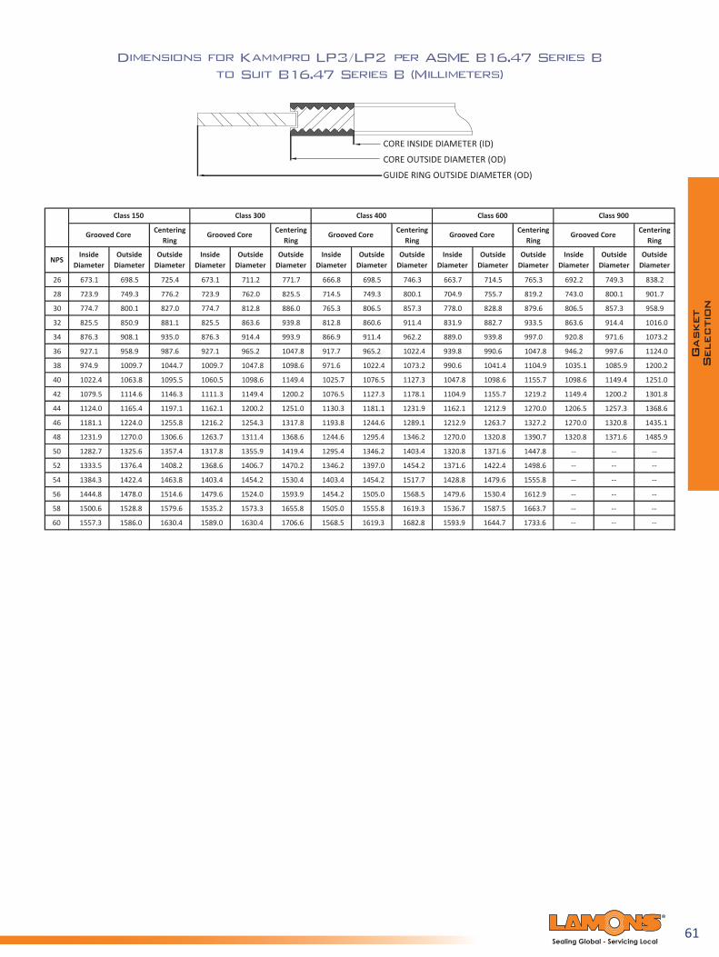
61Sealing Global - Servicing Local
Dimensions for Kammpro LP3/LP2 per ASME B16.47 Series B to Suit B16.47 Series B (Millimeters)
Centering Ring
Centering Ring
Centering Ring
Centering Ring
Centering Ring
NPSInside
DiameterOutside
DiameterOutside
DiameterInside
DiameterOutside
DiameterOutside
DiameterInside
DiameterOutside
DiameterOutside
DiameterInside
DiameterOutside
DiameterOutside
DiameterInside
DiameterOutside
DiameterOutside
Diameter
26 673.1 698.5 725.4 673.1 711.2 771.7 666.8 698.5 746.3 663.7 714.5 765.3 692.2 749.3 838.2
28 723.9 749.3 776.2 723.9 762.0 825.5 714.5 749.3 800.1 704.9 755.7 819.2 743.0 800.1 901.7
30 774.7 800.1 827.0 774.7 812.8 886.0 765.3 806.5 857.3 778.0 828.8 879.6 806.5 857.3 958.9
32 825.5 850.9 881.1 825.5 863.6 939.8 812.8 860.6 911.4 831.9 882.7 933.5 863.6 914.4 1016.0
34 876.3 908.1 935.0 876.3 914.4 993.9 866.9 911.4 962.2 889.0 939.8 997.0 920.8 971.6 1073.2
36 927.1 958.9 987.6 927.1 965.2 1047.8 917.7 965.2 1022.4 939.8 990.6 1047.8 946.2 997.6 1124.0
38 974.9 1009.7 1044.7 1009.7 1047.8 1098.6 971.6 1022.4 1073.2 990.6 1041.4 1104.9 1035.1 1085.9 1200.2
40 1022.4 1063.8 1095.5 1060.5 1098.6 1149.4 1025.7 1076.5 1127.3 1047.8 1098.6 1155.7 1098.6 1149.4 1251.0
42 1079.5 1114.6 1146.3 1111.3 1149.4 1200.2 1076.5 1127.3 1178.1 1104.9 1155.7 1219.2 1149.4 1200.2 1301.8
44 1124.0 1165.4 1197.1 1162.1 1200.2 1251.0 1130.3 1181.1 1231.9 1162.1 1212.9 1270.0 1206.5 1257.3 1368.6
46 1181.1 1224.0 1255.8 1216.2 1254.3 1317.8 1193.8 1244.6 1289.1 1212.9 1263.7 1327.2 1270.0 1320.8 1435.1
48 1231.9 1270.0 1306.6 1263.7 1311.4 1368.6 1244.6 1295.4 1346.2 1270.0 1320.8 1390.7 1320.8 1371.6 1485.9
50 1282.7 1325.6 1357.4 1317.8 1355.9 1419.4 1295.4 1346.2 1403.4 1320.8 1371.6 1447.8 -- -- --
52 1333.5 1376.4 1408.2 1368.6 1406.7 1470.2 1346.2 1397.0 1454.2 1371.6 1422.4 1498.6 -- -- --
54 1384.3 1422.4 1463.8 1403.4 1454.2 1530.4 1403.4 1454.2 1517.7 1428.8 1479.6 1555.8 -- -- --
56 1444.8 1478.0 1514.6 1479.6 1524.0 1593.9 1454.2 1505.0 1568.5 1479.6 1530.4 1612.9 -- -- --
58 1500.6 1528.8 1579.6 1535.2 1573.3 1655.8 1505.0 1555.8 1619.3 1536.7 1587.5 1663.7 -- -- --
60 1557.3 1586.0 1630.4 1589.0 1630.4 1706.6 1568.5 1619.3 1682.8 1593.9 1644.7 1733.6 -- -- --
Class 400
Grooved Core
Class 600
Grooved Core
Class 900
Grooved CoreGrooved Core
Class 150 Class 300
Grooved Core

62Sealing Global - Servicing Local
Dimensions for Kammpro LP3/LP2 per EN 1514 - 6 to
Suit Type A and B Flanges Facings (Inches)
mm Inches10 0.87 1.42 1.81 1.81 1.81 1.81 2.20 2.20 2.20 2.64 2.64 2.64 1.02 1.65 2.01 2.01 2.01 2.01 2.40 2.40 2.40 2.83 2.83 --
2015
1.22 1.85 2.40 2.40 2.40 2.40 -- -- -- -- -- --25 1.42 2.05 2.80 2.80 2.80 2.80 3.23 3.23 3.23 3.27 3.62 4.0932 1.81 2.44 2.60 3.23 3.23 3.23 3.23 -- -- -- -- -- --40 2.09 2.72 2.87 3.62 3.62 3.62 3.62 4.06 4.06 4.06 4.29 4.69 5.3150 2.56 3.19 3.43 4.21 4.21 4.21 4.21 4.45 4.69 4.69 4.88 5.28 5.9165 3.19 3.94 4.06 5.00 5.00 5.00 5.00 5.39 5.63 5.63 6.02 6.69 7.5680 3.74 4.53 4.76 5.59 5.59 5.59 5.59 5.83 6.06 6.06 6.69 7.48 8.15
100 4.65 5.43 5.75 6.38 6.38 6.61 6.61 6.85 7.09 7.09 7.95 9.02 10.08125 5.59 6.38 7.01 7.56 7.56 7.64 7.64 8.27 8.54 8.54 9.53 10.79 11.85150 6.69 7.48 8.35 8.54 8.54 8.82 8.82 9.72 10.12 10.12 11.18 12.24 13.70175 7.68 8.46 9.65 9.72 9.72 10.00 10.43 10.91 11.30 11.18 12.44 14.09 15.83200 8.66 9.45 9.76 11.02 10.71 10.71 11.18 11.42 12.17 12.76 12.76 14.09 15.67 17.40250 10.63 11.42 11.81 13.39 12.87 12.91 13.39 13.86 14.33 15.39 15.28 17.40 19.21 --300 12.60 13.39 14.02 15.75 14.84 15.08 15.75 16.42 16.69 18.03 18.03 21.10 -- --350 14.76 15.55 16.34 -- 17.20 17.44 17.99 18.66 19.13 20.16 -- -- -- --400 16.77 17.72 18.66 -- 19.25 19.49 20.24 21.50 21.38 22.52 -- -- -- --450 18.90 19.92 -- -- 21.22 21.85 -- 22.48 -- -- -- -- -- --500 20.87 22.05 23.15 -- 23.39 24.29 24.57 24.72 25.87 27.72 -- -- -- --600 24.80 26.14 27.56 -- 27.36 28.90 28.78 29.41 30.08 32.01 -- -- -- --700 28.74 30.31 31.97 -- 31.89 31.65 32.80 33.54 34.61 37.40 -- -- -- --800 32.68 34.49 34.88 -- 36.10 35.87 37.09 38.35 38.90 -- -- -- -- --900 36.61 38.66 39.13 -- 40.04 39.80 41.02 42.68 43.62 -- -- -- -- --
1000 40.94 43.23 43.70 -- 44.25 44.41 45.43 47.01 48.03 -- -- -- -- --1200 49.21 51.97 52.52 -- 52.80 52.83 53.70 55.04 57.17 -- -- -- -- --1400 56.69 59.92 -- -- 60.94 60.71 62.13 63.70 -- -- -- -- -- --1600 64.96 6.77 -- -- 69.76 69.45 70.79 72.05 -- -- -- -- -- --1800 72.83 75.35 -- -- 77.64 77.32 78.74 -- -- -- -- -- -- --2000 80.71 83.46 -- -- 85.91 85.35 87.80 -- -- -- -- -- -- --2200 88.58 91.65 -- -- 93.86 93.62 -- -- -- -- -- -- -- --2400 96.85 98.90 -- -- 102.13 -- -- -- -- -- -- -- -- --2600 105.12 107.40 -- -- 110.00 -- -- -- -- -- -- -- -- --2800 113.78 116.22 -- -- 118.66 -- -- -- -- -- -- -- -- --3000 122.05 124.65 -- -- 127.09 -- -- -- -- -- -- -- -- --
See PN 64 to PN 160
See PN 250 to PN 400
PN 40 PN 64
Inches
PN 250 PN 320 PN 400PN 100 PN 160
Inches
DNCore
Inside Diameter
Core Outside Diameter (OD)
PN10/40 PN 64/160 PN 250/400 PN 25
Guide Ring Outside Diameter (OD)
PN 10 PN 16

63Sealing Global - Servicing Local
Dimensions for Kammpro LP3/LP2 per EN 1514 - 6 to
Suit Type A and B Flanges Facings (Millimeters)
mm mm10 22 36 46 46 46 46 56 56 56 67 67 6715 26 42 51 51 51 51 61 61 61 72 72 --20 31 47 61 61 61 61 -- -- -- -- -- --25 36 52 71 71 71 71 82 82 82 83 92 10432 46 62 66 82 82 82 82 -- -- -- -- -- --40 53 69 73 92 92 92 92 103 103 103 109 119 13550 65 81 87 107 107 107 107 113 119 119 124 134 15065 81 100 103 127 127 127 127 137 143 143 153 170 19280 95 115 121 142 142 142 142 148 154 154 170 190 207
100 118 138 146 162 162 168 168 174 180 180 202 229 256125 142 162 178 192 192 194 194 210 217 217 242 274 301150 170 190 212 217 217 224 224 247 257 257 284 311 348175 195 215 245 247 247 254 265 277 287 284 316 358 402200 220 240 248 280 272 272 284 290 309 324 324 358 398 442250 270 290 300 340 327 328 340 352 364 391 388 442 488 --300 320 340 356 400 377 383 400 417 424 458 458 536 -- --350 375 395 415 -- 437 443 457 474 486 512 -- -- -- --400 426 450 474 -- 489 495 514 546 543 572 -- -- -- --450 480 506 -- -- 539 555 -- 571 -- -- -- -- -- --500 530 560 588 -- 594 617 624 628 657 704 -- -- -- --600 630 664 700 -- 695 734 731 747 764 813 -- -- -- --700 730 770 812 -- 810 804 833 852 879 950 -- -- -- --800 830 876 886 -- 917 911 942 974 988 -- -- -- -- --900 930 982 994 -- 1017 1011 1042 1084 1108 -- -- -- -- --
1000 1040 1098 1110 -- 1124 1128 1154 1194 1220 -- -- -- -- --1200 1250 1320 1334 -- 1341 1342 1364 1398 1452 -- -- -- -- --1400 1440 1522 -- -- 1548 1542 1578 1618 -- -- -- -- -- --1600 1650 172 -- -- 1772 1764 1798 1830 -- -- -- -- -- --1800 1850 1914 -- -- 1972 1964 2000 -- -- -- -- -- -- --2000 2050 2120 -- -- 2182 2168 2230 -- -- -- -- -- -- --2200 2250 2328 -- -- 2384 2378 -- -- -- -- -- -- -- --2400 2460 2512 -- -- 2594 -- -- -- -- -- -- -- -- --2600 2670 2728 -- -- 2794 -- -- -- -- -- -- -- -- --2800 2890 2952 -- -- 3014 -- -- -- -- -- -- -- -- --3000 3100 3166 -- -- 3228 -- -- -- -- -- -- -- -- --
DNPN 250 PN 320
Core Outside Diameter (OD) Guide Ring Outside Diameter (OD)
PN 10 PN 16 PN 25 PN 160PN 10/40
Core Inside Diameter
(ID)PN 64/160 PN 250/400 PN 400
See PN 64 to PN 160
See PN 250 to PN 400
PN 40 PN 64
mm mm
PN 100

64Sealing Global - Servicing Local
A note on Kammpro gasket dimensions
Kammpro gaskets are an ideal upgrade for equipment applications where standard spiral wound gaskets, double jacketed designs, and corrugated metallic gaskets are commonly used.
Kammpro LP1 dimensions can be the same as Style W or Style 300/310 gaskets that are seated in large male/female, large tongue/groove, and small tongue/groove joints. Technically, the dimensions that are specifi ed for large spiral wound ASME B16.20 for ASME B16.47 Series A and B fl anges can still apply for the Kammpro Gaskets per LP3/LP2 design.
Kammpro LP3/LP2 Tolerances per ASME B16.20 Specification:
• Core inside diameter for NPS ½ to 24 is +1/64”, - 0” (+0.4 mm, - 0 mm)
• Core outside diameter for NPS ½ to 24 is +0”, -1/64” (+0 mm, - 0.4 mm)
• Guide ring outside diameter for NPS ½ to 24 is ±1/32” (±0.8 mm)
Kammpro LP3/LP2 Tolerances per EN 1514-6 Specification:
• Core inside diameter for DN 10 through DN 1000 is +1/64”, - 0” (+0.4 mm, - 0 mm)
• Core outside diameter for DN 10 through DN 1000 is +0”, -1/64” (+0 mm, - 0.4 mm)
• Core inside diameter for DN 1000 and larger is +3/64”, -0” (+1.0 mm, - 0 mm)
• Core outside diameter for DN 1000 and larger is +0”, -3/64” (+0 mm, - 1.0mm)
• Guide ring outside diameter is ±1/32” (±0.8 mm)

65Sealing Global - Servicing Local
Lamons SpiraSeal® Product F amily
Spiral wound gaskets have become extremely popular due to the wide variety of available styles and sizes. Spiral wound gaskets can be fabricated of any metal which is available in thin strip and which can be welded; therefore, they can be used against virtually any corrosive medium dependent upon the choice of the metal and filler. They can be used over the complete temperature range from cryogenic to approximately 2000ºF (1093ºC). This type of gasket can be used in all pressures from vacuum to the standard 2500 pressure class flange ratings. Spiral wound gaskets can also be manufactured with variable densities, i.e. relatively low density gaskets for vacuum service up to extremely high density gaskets having a seating stress of approximately 30,000 psi (207 MPa). The softer gaskets would require a seating stress in the range of 5,000 psi (34 MPa).
Variable DensitySpiral wound gaskets are manufactured by alternately winding strips of metal and soft fillers on the outer edge of winding mandrels that determine the inside dimensions of the wound component. In the winding process, the alternating plies are maintained under pressure. Varying the pressure during the winding operation and/or the thickness of the soft filler, the density of the gasket can be controlled over a wide range. As a general rule, low winding pressure and thick soft fillers are used for low pressure applications. Thin fillers and high pressure loads are used for high pressure applications. This, of course, would account for the higher bolt loads that have to be applied to the gasket in high pressure applications. In addition to all these advantages of the spiral wound gasket, they are relatively low cost.
A vailable sizes and ThicknessesLamons spiral wound gaskets are available in thicknesses of 0.0625” (1.5 mm), 0.100” (2.5 mm), 0.125” (3 mm), 0.175” (4 mm), 0.250” (6.4 mm), and 0.285” (7 mm). The chart on page 47 indicates the size range that can normally be fabricated in the various thicknesses along with the recommended compressed thickness of each and the maximum flange width.
Flange Surface FinishUse of spiral wound gaskets gives the designer and the user a wider tolerance for flange surface finishes than other metallic gaskets. While they can be used against most commercially available flange surface finishes, experience has indicated that the appropriate flange surface finishes used with spiral wound gaskets are as follows:
• 125 to 250 AARH optimum
• 500 AARH maximum

66Sealing Global - Servicing Local
Available SpiraSeal® Styles
Lamons spiral wound gaskets are available in a variety of styles to suit the particular fl ange facing being utilized on the fl anges.
Lamons Style WStyle W gaskets are SpiraSeal® windings only. No inner or outer ring is utilized. Used in a variety of different applications, they may be furnished in many different sizes and thicknesses.
Style W gaskets are made in standard sizes to fi t:
A. Large tongue and groove joints, 1/2 to 24 NPS, standard pressures;
B. Small tongue and groove joints, 1/2 to 24 NPS, standard pressures; and,
C. Large male and female joints 1/4 to 24 NPS, standard pressures,
Lamons Style WRStyle WR gaskets consist of a spiral wound sealing component with a solid metal outer guide ring. The outer guide ring serves to center the gasket properly in the fl ange joint, acts as an anti-blowout device, provides radial support for the spiral wound component, and acts as a compression gauge to prevent the spiral wound component from being over crushed. Normally the outer guide rings are furnished in mild steel, but can be supplied in other metals when required by operating conditions.
Lamons Style WRIStyle WRI is identical to style WR, with the addition of an inner ring. The inner ring also serves several functions. Primarily, it provides radial support for the gasket on the ID to help prevent the occurrences of buckling or imploding. The inner ring also serves as an additional compression limiter. Its ID is normally sized slightly larger than the ID of the fl ange bore, minimizing turbulence in process fl ow. The inner rings are normally supplied in the same material as the spiral wound component. Lamons normally manufactures standard Style WR and WRI spiral wound gaskets to ASME B16.20, designed to suit ASME B16.5 and ASME B16.47 fl anges.
Lamons Style WRI-LEStyle WRI-LE design is the optimum choice when gasket high density and low emissions are a must. The improved spiral wound design incorporates the typical essentials such as a carbon steel guide ring, along with a stainless steel inner ring.
Manufacturing procedures for the low emissions gasket precisely regulate the amount of metal wire wraps per inch; this higher number of wraps helps create a more robust and dense gasket, which in turn reduce emissions. Machinery settings are carefully regulated and set to higher pressure settings which generate higher tension on the winding to densify and extrude the fi ller to a minimum of 0.008” (0.2032 mm) above the winding metal surface. This extruded material creates a thin barrier between the winding surface and fl ange sealing surface to help fi ll minor fl ange surface blemishes and inconsistencies. Flanges in the 150 to 2500 pressure class range will benefi t from this leading edge design.

67Sealing Global - Servicing Local
Lamons Style WRI-LCStyle WRI-LC gaskets provide a seal at relatively lower seating stress. This means that our design requires less bolt load to seat, yet still has the recovery like a standard spiral wound. The WRI-LC gasket is typical to Class 150 and 300 flanges, where users have a concern with insufficient potential of pre-load. But, the density of the WRI-LC gasket can be varied to meet virtually any requirement. Electronic controls on Lamons’ SpiraSeal machines assure high quality precision welding with equal spacing, the correct number of metal plies on the gasket inside periphery, proper ratio of metal to filler, proper number of metal plies on the outside and spot welds on the OD.
Lamons Style WRI-HTGStyle WRI-HTG gaskets combine the corrosion and oxidation resistance of mica with the “sealability” of flexible graphite. The mica material, in conjunction with the metal spirals serves as a barrier between oxidizing process conditions and/or external air and the graphite. While Inconel® X-750 is commonly selected as the winding metal, any alloy can be selected. The overall effective rating of the HTG configuration can be utilized in temperatures of up to 1500°F (815°C). Higher temperatures can be realized given further consultation with Lamons Engineering Department.
Lamons Style WRI-LPDesigned for highly corrosive environments, Style WRI-LP is a Spiral wound gasket with a conventional outer guide ring and a “Kammpro” style LP1 inner ring. This dual sealing design engages the raised face completely from the OD to the bore. The winding can be constructed with the required metal and soft filler specified by the user. The “Kammpro” inner ring metal can be ordered in any alloy, such as Monel®, or in carbon steel. A carbon steel inner ring can be given a protective PTFE coating for increased chemical resistance. The Kammpro inner ring is faced typically with either 0.020” (0.5 mm) thick EPTFE or graphite. The WRI-LP has seen wide-spread approvals for Hydrofluoric Acid (HF) service, although this design has much further potential. Its main advantages are: no metal contact with the media; chemical resistance; fire safe design; sizing to meet ASME B16.5; available in large diameter and for special flanges.
Lamons InhibitorLamons Inhibitor gasket provides corrosion resistance in the most extreme conditions. It combines a HTG filler configuration with highest purity graphite, and a Kammpro inner ring laminated with soft PTFE material. The design of the Inhibitor gasket utilizes the Kammpro inner ring to provide the primary sealing interface. The inner ring material and its covering layer are inert in terms of corrosion through contact with dissimilar materials. This fire safe design incorporates the sealing integrity of highest purity graphite in conjunction with mica on the ID and OD, preventing the entrance of further corrosive conditions to the media.

68Sealing Global - Servicing Local
Lamons Style WR-ABInward buckling of spiral wound gaskets is sometimes a concern in industry today. Work is ongoing through various industry committees to improve the standard in this regard. Some end users do not want to use inner rings due to cost or bore intrusion - to address this stance, Lamons offers Style WR-AB. By creating a space for expansion between the OD of the winding and the outer ring, the buckling along the inside could be reduced. This feature, combined with a reinforced inside circumference, help to further reduce the likelihood of inward buckling after installation.
Lamons Style WRI-HFThis gasket was developed for Hydrofl uoric (HF) acid applications. It consists of a Monel® and PTFE winding with a carbon steel centering ring and a PTFE inner ring. The carbon steel outer ring can be coated with special HF acid detecting paint if desired. The PTFE inner ring reduces corrosion to the fl anges between the bore of the pipe and the ID of the spiral wound sealing element.
Lamons Style WRI-RJThe style WRI-RJ gasket is identical to a Style WRI in construction features but is specially sized to be used as a replacement gasket for fl anges machined to accept oval or octagonal ring joint gaskets. The sealing component is located between the IDof the groove machined in the fl ange and the fl ange bore. These are intended to be used as replacement parts and are considered a maintenance item. In new construction, where spiral wound gaskets are intended to be used, raised face fl anges should be utilized.
Lamons Style MW, MWC & MWIThese gaskets are available in round, obround, and oval shapes and are used for standard manhole cover plates. When spiral wound manhole gaskets with a straight side are required, it is necessary that some curvature be allowable, given to the fact that spiral wound gaskets are wrapped under tension and therefore tend to buckle inward when the gaskets are removed from the winding mandrel. As a rule of thumb, the ratio of the long ID to the short ID should not exceed three to one.
Lamons Style HStyle H gaskets are for use on boiler hand hole and tubecap assemblies. They are available in round, square, rectangular, diamond, obround, oval and pear shapes. Lamons has tooling available for manufacturing most of the standard handhold and tubecap sizes of the various boiler manufacturers. However, these are also available in special sizes and shapes. (To order special gaskets, dimensional drawings or sample cover plates should be provided in order to assure proper fi t.)
MW MWC
MWI

69Sealing Global - Servicing Local
Lamons Style WP & WRPThese gaskets are similar to Style W and Style WR, with the addition of pass partitions for use with shell and tube heat exchangers. Partitions are normally supplied as double-jacketed construction, made of the same material as the spiral wound component. The partition strips can be soft soldered, tack welded or silver soldered to the spiral wound component. The double-jacketed partition strips are normally slightly thinner than the spiral wound component in order to minimize the bolt loading required to properly seat the gasket.
Lamons Style LThe spiral wound components of Style L are identical to those of Style W and in addition have a wire loop welded to the outer periphery of the gasket, sized so as to fit over diametrically opposite bolts, for proper centering of the spiral wound component on the gasket seating surface. Whenever possible, it is recommended that a Style WR gasket be used in lieu of a Style L gasket because of the obvious advantages of the outer solid metal guide ring. The Style L is considerably more difficult to produce than the Style WR and therefore more expensive.
Spiral Wound Gasket Dimensions for Pipe FlangesSpiral wound gaskets must be sized to ensure the winding component is seated properly between flat surfaces. If it protrudes beyond a raised face or into a flange bore, mechanical damage and leakage may occur.
Style W typically is applied in confined groove type flanges, and it is sized by the following formulas:
Gasket is confined on the Inside Diameter (ID) and Outside Diameter (OD):Gasket Inside Diameter (ID) = Groove Inside Diameter (ID) + 1/16” (1.5 mm)Gasket Outside Diameter (OD) = Groove Outside Diameter (OD) – 1/16” (1.5 mm)
Gasket is confined on the Outside Diameter (OD):Gasket Inside Diameter (ID) = Bore + Minimum 1/4” (6.4 mm)Gasket Outside Diameter (OD) = Recess Outside Diameter (OD) - 1/16” (1.5 mm)
Limitation of Size & Thickness
*These limitations are intended as a general guide only. Materials of construction and flange width of gasket can affect the limitations listed.
Inches mm Inches mm Inches mm Inches mm0.063 1.59 9 229 0.375 9.53 0.050/0.055 1.27/1.390.100 2.54 12 305 0.500 12.70 0.075/0.080 1.91/2.030.125 3.18 40 1016 0.750 19.05 0.090/0.100 2.29/2.540.175 4.45 75 1905 1.000 25.40 0.125/0.135 3.18/3.430.250 6.35 160 4064 1.250 31.75 0.180/0.200 4.57/5.080.285 7.24 160 4064 1.250 31.75 0.200/0.220 5.08/5.59
Recommended Compressed Thickness
Maximum Flange Width*
Maximum Inside Diameter (ID)*Gasket Thickness
WP
WRP
Limitations of Size & Thickness
70Sealing Global - Servicing Local
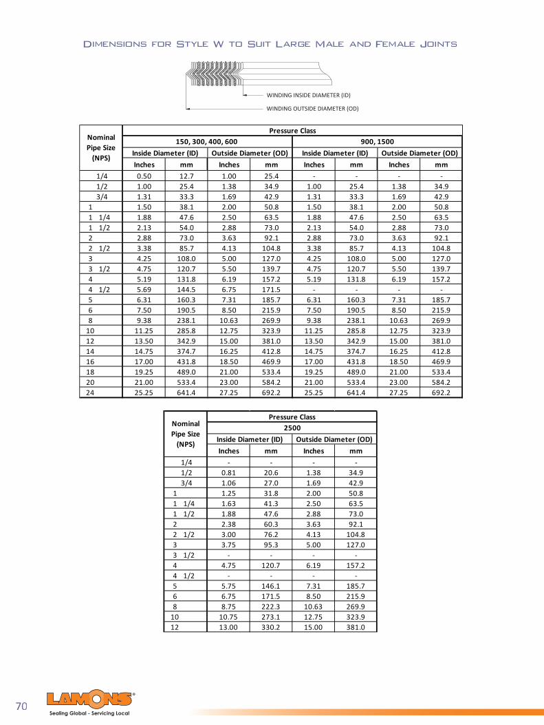
Dimensions for Style W to Suit Large Male and Female Joints
WINDING INSIDE DIAMETER (ID)
WINDING OUTSIDE DIAMETER (OD)
Inches mm Inches mm Inches mm Inches mm1/4 0.50 12.7 1.00 25.4 - - - -1/2 1.00 25.4 1.38 34.9 1.00 25.4 1.38 34.93/4 1.31 33.3 1.69 42.9 1.31 33.3 1.69 42.9
1 1.50 38.1 2.00 50.8 1.50 38.1 2.00 50.81 1/4 1.88 47.6 2.50 63.5 1.88 47.6 2.50 63.51 1/2 2.13 54.0 2.88 73.0 2.13 54.0 2.88 73.02 2.88 73.0 3.63 92.1 2.88 73.0 3.63 92.12 1/2 3.38 85.7 4.13 104.8 3.38 85.7 4.13 104.83 4.25 108.0 5.00 127.0 4.25 108.0 5.00 127.03 1/2 4.75 120.7 5.50 139.7 4.75 120.7 5.50 139.74 5.19 131.8 6.19 157.2 5.19 131.8 6.19 157.24 1/2 5.69 144.5 6.75 171.5 - - - -5 6.31 160.3 7.31 185.7 6.31 160.3 7.31 185.76 7.50 190.5 8.50 215.9 7.50 190.5 8.50 215.98 9.38 238.1 10.63 269.9 9.38 238.1 10.63 269.9
10 11.25 285.8 12.75 323.9 11.25 285.8 12.75 323.912 13.50 342.9 15.00 381.0 13.50 342.9 15.00 381.014 14.75 374.7 16.25 412.8 14.75 374.7 16.25 412.816 17.00 431.8 18.50 469.9 17.00 431.8 18.50 469.918 19.25 489.0 21.00 533.4 19.25 489.0 21.00 533.420 21.00 533.4 23.00 584.2 21.00 533.4 23.00 584.224 25.25 641.4 27.25 692.2 25.25 641.4 27.25 692.2
Pressure Class
Inside Diameter (ID)
NominalPipe Size
(NPS) Outside Diameter (OD) Inside Diameter (ID) Outside Diameter (OD)900, 1500150, 300, 400, 600
Inches mm Inches mm1/4 - - - -1/2 0.81 20.6 1.38 34.93/4 1.06 27.0 1.69 42.9
1 1.25 31.8 2.00 50.81 1/4 1.63 41.3 2.50 63.51 1/2 1.88 47.6 2.88 73.02 2.38 60.3 3.63 92.12 1/2 3.00 76.2 4.13 104.83 3.75 95.3 5.00 127.03 1/2 - - - -4 4.75 120.7 6.19 157.24 1/2 - - - -5 5.75 146.1 7.31 185.76 6.75 171.5 8.50 215.98 8.75 222.3 10.63 269.9
10 10.75 273.1 12.75 323.912 13.00 330.2 15.00 381.0
Pressure Class2500
Inside Diameter (ID) Outside Diameter (OD)
NominalPipe Size
(NPS)

71Sealing Global - Servicing Local
Style W Gasket Tolerances:
Gasket Diameter (Inches) Inside Diameter (ID) Outside Diameter (OD)Up to 1" (+3/64", - 0.00") (+0.00", - 1/32")1" to 24" (+1/32", - 0.00") (+0.00", - 1/32")
24" to 36" (+3/64", - 0.00") (+0.00", - 1/16")36" to 60" (+1/16", - 0.00") (+0.00", - 1/16")
60" and above (+3/32", - 0.00") (+0.00", - 3/32")
Gasket Diameter (mm) Inside Diameter (ID) Outside Diameter (OD)Up to 25.4 mm (+1.2 mm, - 0.00 mm) (+0.00 mm, - 0.8 mm)
25.4 mm to 610 mm (+0.8 mm, - 0.00 mm) (+0.00 mm, - 0.8 mm)610 mm to 914 mm (+1.2 mm, - 0.00 mm) (+0.00 mm, - 1.6 mm)
914 mm to 1524 mm (+1.6 mm, - 0.00 mm) (+0.00 mm, - 1.6 mm)1524 mm and above (+2.4 mm, - 0.00 mm) (+0.00 mm, - 2.4 mm)
Thickness +0.015” - 0.00” (+0.381 mm, - 0.00 mm) on special gaskets with: a. Less than 1” (25.4 mm) ID greater that 26” (660.4 mm) ID. b. PTFE fillers c. 1” (25.4 mm) or larger flange width.Thickness + 0.010 - 0.000” (+0.254 mm, - 0.00 mm) for most other sizes and materials.
Dimensions for Style W
WINDING INSIDE DIAMETER (ID)
WINDING OUTSIDE DIAMETER (OD)
Inches mm Inches mm1/2 1.00 25.4 1.38 34.93/4 1.31 33.3 1.69 42.9
1 1.50 38.1 2.00 50.81 1/4 1.88 47.6 2.50 63.51 1/2 2.13 54.0 2.88 73.02 2.88 73.0 3.63 92.12 1/2 3.38 85.7 4.13 104.83 4.25 108.0 5.00 127.03 1/2 4.75 120.7 5.50 139.74 5.19 131.8 6.19 157.25 6.31 160.3 7.31 185.76 7.50 190.5 8.50 215.98 9.38 238.1 10.63 269.9
10 11.25 285.8 12.75 323.912 13.50 342.9 15.00 381.014 14.75 374.7 16.25 412.816 16.75 425.5 18.50 469.918 19.25 489.0 21.00 533.420 21.00 533.4 23.00 584.224 25.25 641.4 27.25 692.2
* 2500# only thru 12" NPS
Pressure Class150-2500*
Inside Diameter(ID)
Outside Diameter(OD)
Nominal Pipe Size
(NPS)Inches mm Inches mm
1/2 1.00 25.4 1.38 34.93/4 1.31 33.3 1.69 42.9
1 1.50 38.1 1.88 47.61 1/4 1.88 47.6 2.25 57.21 1/2 2.13 54.0 2.50 63.52 2.88 73.0 3.25 82.62 1/2 3.38 85.7 3.75 95.33 4.25 108.0 4.63 117.53 1/2 4.75 120.7 5.13 130.24 5.19 131.8 5.69 144.55 6.31 160.3 6.81 173.06 7.50 190.5 8.00 203.28 9.38 238.1 10.00 254.0
10 11.25 285.8 12.00 304.812 13.50 342.9 14.25 362.014 14.75 374.7 15.50 393.716 16.75 425.5 17.63 447.718 19.25 489.0 20.13 511.220 21.00 533.4 22.00 558.824 25.25 641.4 26.25 666.8
* 2500# only thru 12" NPS
Pressure Class150-2500*
Inside Diameter(ID)
Outside Diameter(OD)
Nominal Pipe Size
(NPS)
For Large Tongue and Groove Joints
For Small Tongue and Groove Joints

72Sealing Global - Servicing Local
Inches mm Inches mm Inches mm Inches mmInches mm Inches mm Inches mm Inches mm
Inches mm Inches mm Inches mm Inches mm
Inches mm Inches mm Inches mm Inches mm
1/4* - - 0.50 12.7 0.88 22.2 1.75 44.51/4* - - 0.50 12.7 0.88 22.2 1.75 44.5
1/4* - - 0.50 12.7 0.88 22.2 1.75 44.5
1/4* - - 0.50 12.7 0.88 22.2 1.75 44.5
1/2 0.56 14.2 0.75 19.1 1.25 31.8 1.88 47.61/2 0.56 14.2 0.75 19.1 1.25 31.8 2.13 54.0
1/2 0.56 14.2 0.75 19.1 1.25 31.8 2.13 54.0
1/2 0.56 14.2 0.75 19.1 1.25 31.8 2.13 54.0
3/4 0.81 20.6 1.00 25.4 1.56 39.7 2.25 57.23/4 0.81 20.6 1.00 25.4 1.56 39.7 2.63 66.7
3/4 0.81 20.6 1.00 25.4 1.56 39.7 2.63 66.7
3/4 0.81 20.6 1.00 25.4 1.56 39.7 2.63 66.7
1 1.06 26.9 1.25 31.8 1.88 47.6 2.63 66.71 1.06 26.9 1.25 31.8 1.88 47.6 2.88 73.0
1 1.06 26.9 1.25 31.8 1.88 47.6 2.88 73.0
1 1.06 26.9 1.25 31.8 1.88 47.6 2.88 73.0
1 1/4 1.50 38.1 1.88 47.6 2.38 60.3 3.00 76.21 1/4 1.50 38.1 1.88 47.6 2.38 60.3 3.25 82.6
1 1/4 1.50 38.1 1.88 47.6 2.38 60.3 3.25 82.6
1 1/4 1.50 38.1 1.88 47.6 2.38 60.3 3.25 82.6
1 1/2 1.75 44.5 2.13 54.0 2.75 69.9 3.38 85.71 1/2 1.75 44.5 2.13 54.0 2.75 69.9 3.75 95.3
1 1/2 1.75 44.5 2.13 54.0 2.75 69.9 3.75 95.3
1 1/2 1.75 44.5 2.13 54.0 2.75 69.9 3.75 95.3
2 2.19 55.6 2.75 69.9 3.38 85.7 4.13 104.82 2.19 55.6 2.75 69.9 3.38 85.7 4.38 111.1
2 2.19 55.6 2.75 69.9 3.38 85.7 4.38 111.1
2 2.19 55.6 2.75 69.9 3.38 85.7 4.38 111.1
2 1/2 2.62 66.5 3.25 82.6 3.88 98.4 4.88 123.82 1/2 2.62 66.5 3.25 82.6 3.88 98.4 5.13 130.2
2 1/2 2.62 66.5 3.25 82.6 3.88 98.4 5.13 130.2
2 1/2 2.62 66.5 3.25 82.6 3.88 98.4 5.13 130.2
3 3.19 81.0 4.00 101.6 4.75 120.7 5.38 136.53 3.19 81.0 4.00 101.6 4.75 120.7 5.88 149.2
3 3.19 81.0 4.00 101.6 4.75 120.7 5.88 149.2
3 3.19 81.0 4.00 101.6 4.75 120.7 5.88 149.2
3 1/2* 3.50 88.9 4.50 114.3 5.25 133.4 6.38 161.93 1/2* 4.50 114.3 5.25 133.4 6.50 165.1
3 1/2* 4.13 104.8 5.25 133.4 6.38 161.9
3 1/2 4.13 104.8 5.25 133.4 6.38 161.9
4 4.19 106.4 5.00 127.0 5.88 149.2 6.88 174.64 4.19 106.4 5.00 127.0 5.88 149.2 7.13 181.0
4 4.04 102.6 4.75 120.7 5.88 149.2 7.00 177.8
4 4.04 102.6 4.75 120.7 5.88 149.2 7.63 193.7
5 5.19 131.8 6.13 155.6 7.00 177.8 7.75 196.95 5.19 131.8 6.13 155.6 7.00 177.8 8.50 215.9
5 5.05 128.3 5.81 147.6 7.00 177.8 8.38 212.7
5 5.05 128.3 5.81 147.6 7.00 177.8 9.50 241.3
6 6.19 157.2 7.19 182.6 8.25 209.6 8.75 222.36 6.19 157.2 7.19 182.6 8.25 209.6 9.88 250.8
6 6.10 154.9 6.88 174.6 8.25 209.6 9.75 247.7
6 6.10 154.9 6.88 174.6 8.25 209.6 10.50 266.7
8 8.50 215.9 9.19 233.4 10.38 263.5 11.00 279.48 8.50 215.9 9.19 233.4 10.38 263.5 12.13 308.0
8 8.10 205.7 8.88 225.4 10.38 263.5 12.00 304.8
8 8.10 205.7 8.88 225.4 10.38 263.5 12.63 320.7
10 10.56 268.2 11.31 287.3 12.50 317.5 13.38 339.710 10.56 268.2 11.31 287.3 12.50 317.5 14.25 362.0
10 10.05 255.3 10.81 274.6 12.50 317.5 14.13 358.8
10.05 255.3 10.81 274.6 12.50 317.5 15.75 400.1
12 12.50 317.5 13.38 339.7 14.75 374.7 16.13 409.612 12.50 317.5 13.38 339.7 14.75 374.7 16.63 422.3
12 12.10 307.3 12.88 327.0 14.75 374.7 16.50 419.1
1210
12.10 307.3 12.88 327.0 14.75 374.7 18.00 457.2
14 13.75 349.3 14.63 371.5 16.00 406.4 17.75 450.914 13.75 349.3 14.63 371.5 16.00 406.4 19.13 485.8
14 13.50 342.9 14.25 362.0 16.00 406.4 19.00 482.6
14 13.50 342.9 14.25 362.0 16.00 406.4 19.38 492.1
16 15.75 400.1 16.63 422.3 18.25 463.6 20.25 514.416 15.75 400.1 16.63 422.3 18.25 463.6 21.25 539.8
16 15.35 389.9 16.25 412.8 18.25 463.6 21.13 536.6
16 15.35 389.9 16.25 412.8 18.25 463.6 22.25 565.2
18 17.69 449.3 18.69 474.7 20.75 527.1 21.63 549.318 17.69 449.3 18.69 474.7 20.75 527.1 23.50 596.9
18 17.25 438.2 18.50 469.9 20.75 527.1 23.38 593.7
18 17.25 438.2 18.50 469.9 20.75 527.1 24.13 612.8
20 19.69 500.1 20.69 525.5 22.75 577.9 23.88 606.420 19.69 500.1 20.69 525.5 22.75 577.9 25.75 654.1
20 19.25 489.0 20.50 520.7 22.75 577.9 25.50 647.7
20 19.25 489.0 20.50 520.7 22.75 577.9 26.88 682.6
24 23.75 603.3 24.75 628.7 27.00 685.8 28.25 717.624 23.75 603.3 24.75 628.7 27.00 685.8 30.50 774.7
24 23.25 590.6 24.75 628.7 27.00 685.8 30.25 768.4
24 23.25 590.6 24.75 628.7 27.00 685.8 31.13 790.6
*Not Listed in ASME B16.20
*Not Listed in ASME B16.20
Inches mm Inches mm Inches mm Inches mm
Inches mm Inches mm Inches mm Inches mm
Inches mm Inches mm Inches mm Inches mm1/4* - - - - - - - -
1/4* - - - - - - - -
1/4* - - - - - - - -1/2 0.56 14.2 0.75 19.1 1.25 31.8 2.50 63.5
1/2 0.56 14.2 0.75 19.1 1.25 31.8 2.50 63.5
1/2 0.56 14.2 0.75 19.1 1.25 31.8 2.75 69.93/4 0.81 20.6 1.00 25.4 1.56 39.7 2.75 69.9
3/4 0.81 20.6 1.00 25.4 1.56 39.7 2.75 69.9
3/4 0.81 20.6 1.00 25.4 1.56 39.7 3.00 76.21 1.06 26.9 1.25 31.8 1.88 47.6 3.13 79.4
1 1.06 26.9 1.25 31.8 1.88 47.6 3.13 79.4
1 1.06 26.9 1.25 31.8 1.88 47.6 3.38 85.71 1/4 1.31 33.3 1.56 39.7 2.38 60.3 3.50 88.9
1 1/4 1.31 33.3 1.56 39.7 2.38 60.3 3.50 88.9
1 1/4 1.31 33.3 1.56 39.7 2.38 60.3 4.13 104.81 1/2 1.63 41.4 1.88 47.6 2.75 69.9 3.88 98.4
1 1/2 1.63 41.4 1.88 47.6 2.75 69.9 3.88 98.4
1 1/2 1.63 41.4 1.88 47.6 2.75 69.9 4.63 117.52 2.06 52.3 2.31 58.7 3.38 85.7 5.63 142.9
2 2.06 52.3 2.31 58.7 3.38 85.7 5.63 142.9
2 2.06 52.3 2.31 58.7 3.38 85.7 5.75 146.12 1/2 2.50 63.5 2.75 69.9 3.88 98.4 6.50 165.1
2 1/2 2.50 63.5 2.75 69.9 3.88 98.4 6.50 165.1
2 1/2 2.50 63.5 2.75 69.9 3.88 98.4 6.63 168.33 3.10 78.7 3.75 95.3 4.75 120.7 6.63 168.3
3 3.10 78.7 3.63 92.1 4.75 120.7 6.88 174.6
3 3.10 78.7 3.63 92.1 4.75 120.7 7.75 196.93 1/2* 4.13 104.8 5.25 133.4 7.50 190.5
3 1/2* 4.13 104.8 5.25 133.4 7.38 187.3
3 1/2* - - - - - -4 4.04 102.6 4.75 120.7 5.88 149.2 8.13 206.4
4 3.85 97.8 4.63 117.5 5.88 149.2 8.25 209.6
4 3.85** 97.8** 4.63 117.5 5.88 149.2 9.25 235.05 5.05 128.3 5.81 147.6 7.00 177.8 9.75 247.7
5 4.90 124.5 5.63 142.9 7.00 177.8 10.00 254.0
5 4.90** 124.5** 5.63 142.9 7.00 177.8 11.00 279.46 6.10 154.9 6.88 174.6 8.25 209.6 11.38 288.9
6 5.80 147.3 6.75 171.5 8.25 209.6 11.13 282.6
6 5.80** 147.3** 6.75 171.5 8.25 209.6 12.50 317.58 7.75 196.9 8.75 222.3 10.13 257.2 14.13 358.8
8 7.75 196.9 8.50 215.9 10.13 257.2 13.88 352.4
8 7.75** 196.9** 8.50 215.9 10.13 257.2 15.25 387.410 9.69 246.1 10.88 276.2 12.25 311.2 17.13 435.0
10 9.69 246.1 10.50 266.7 12.25 311.2 17.13 435.0
10 9.69** 246.1** 10.63 269.9 12.25 311.2 18.75 476.312 11.50 292.1 12.75 323.9 14.50 368.3 19.63 498.5
12 11.50** 292.1** 12.75 323.9 14.50 368.3 20.50 520.7
12 11.50** 292.1** 12.50 317.5 14.50 368.3 21.63 549.314 12.63 320.8 14.00 355.6 15.75 400.1 20.50 520.7
14 12.63** 320.8** 14.25 362.0 15.75 400.1 22.75 577.9
*Not Listed in ASME B16.2016 14.75 374.7 16.25 412.8 18.00 457.2 22.63 574.7
16 14.50** 368.3** 16.00 406.4 18.00 457.2 25.25 641.4
** Inner rings are required
18 16.75 425.5 18.25 463.6 20.50 520.7 25.13 638.2
18 16.75** 425.5** 18.25 463.6 20.50 520.7 27.75 704.9
20 19.00 482.6 20.50 520.7 22.50 571.5 27.50 698.5
20 18.75** 476.3** 20.25 514.4 22.50 571.5 29.75 755.7
24 23.25** 590.6 24.75 628.7 26.75 679.5 33.00 838.2
24 22.75** 577.9** 24.25 616.0 26.75 679.5 35.50 901.7
*Not Listed in ASME B16.20 ** Inner rings are required
Class 600
Winding Outside Diameter (OD)
Winding Outside Diameter (OD)
Nominal Pipe Size (NPS) Winding Inside
Diameter (ID)
Class 400
Guide Ring Outside Diameter (OD)
Winding Inside Diameter (ID)
Winding Outside Diameter (OD)
Winding Inside Diameter (ID)
Guide Ring Outside Diameter (OD)
Inner Ring Inside Diameter (ID)
Class 1500
Winding Outside Diameter (OD)
Winding Outside Diameter (OD)
Winding Inside Diameter (ID)
Winding Outside Diameter (OD)
Inner Ring Inside Diameter (ID)
Guide Ring Outside Diameter (OD)
Winding Outside Diameter (OD)
Class 900
Winding Inside Diameter (ID)
Nominal Pipe Size (NPS) Guide Ring Outside
Diameter (OD)
Inner Ring Inside Diameter (ID)
Inner Ring Inside Diameter (ID)
Nominal Pipe Size (NPS)
Class 150Nominal Pipe
Size (NPS)
Winding Inside Diameter (ID)
Guide Ring Outside Diameter (OD)
Class 300
Inner Ring Inside Diameter (ID)
Inner Ring Inside Diameter (ID)
Inner Ring Inside Diameter (ID)
Winding Inside Diameter (ID)
Guide Ring Outside Diameter (OD)
Nominal Pipe Size (NPS)
Nominal Pipe Size (NPS)
Class 2500Nominal Pipe
Size (NPS) Guide Ring Outside Diameter (OD)
3.50 88.9
3.50 88.93.50 88.9
3.50 88.9 3.50 88.9
3.50 88.9
Dimensions for Style WRI per ASME B16.20
to Suit ASME B16.5 Flanges
Double Color Coding for SpiraSeal® Gaskets per ASME B16.20
Metallic Windings
304 SS
316L SS
317L SS
347 SS
321 SS
Monel®
Inconel® 600/625
Nickel
Yellow
Green
Maroon
Blue
Turquoise
Orange
Gold
Red
lncoloy 800/825
Titanium
Alloy 20
Carbon Steel
Hastelloy® “B”
Hastelloy® “C”
Phos. Bronze
White
Purple
Black
Silver
Brown
Beige
Copper
Non-Metallic Fillers
PTFE
Ceramic
Flexible Graphite
Phyllosilicate (HTG)
White Stripe
Light Green Stripe
Gray Stripe
Light Blue Stripe
INNER RING INSIDE DIAMETER (ID)
WINDING INSIDE DIAMETER (ID)
WINDING OUTSIDE DIAMETER (OD)GUIDE RING OUTSIDE DIAMETER (OD)

73Sealing Global - Servicing Local
Inches mm Inches mm Inches mm Inches mmInches mm Inches mm Inches mm Inches mm
Inches mm Inches mm Inches mm Inches mm
Inches mm Inches mm Inches mm Inches mm
1/4* - - 0.50 12.7 0.88 22.2 1.75 44.51/4* - - 0.50 12.7 0.88 22.2 1.75 44.5
1/4* - - 0.50 12.7 0.88 22.2 1.75 44.5
1/4* - - 0.50 12.7 0.88 22.2 1.75 44.5
1/2 0.56 14.2 0.75 19.1 1.25 31.8 1.88 47.61/2 0.56 14.2 0.75 19.1 1.25 31.8 2.13 54.0
1/2 0.56 14.2 0.75 19.1 1.25 31.8 2.13 54.0
1/2 0.56 14.2 0.75 19.1 1.25 31.8 2.13 54.0
3/4 0.81 20.6 1.00 25.4 1.56 39.7 2.25 57.23/4 0.81 20.6 1.00 25.4 1.56 39.7 2.63 66.7
3/4 0.81 20.6 1.00 25.4 1.56 39.7 2.63 66.7
3/4 0.81 20.6 1.00 25.4 1.56 39.7 2.63 66.7
1 1.06 26.9 1.25 31.8 1.88 47.6 2.63 66.71 1.06 26.9 1.25 31.8 1.88 47.6 2.88 73.0
1 1.06 26.9 1.25 31.8 1.88 47.6 2.88 73.0
1 1.06 26.9 1.25 31.8 1.88 47.6 2.88 73.0
1 1/4 1.50 38.1 1.88 47.6 2.38 60.3 3.00 76.21 1/4 1.50 38.1 1.88 47.6 2.38 60.3 3.25 82.6
1 1/4 1.50 38.1 1.88 47.6 2.38 60.3 3.25 82.6
1 1/4 1.50 38.1 1.88 47.6 2.38 60.3 3.25 82.6
1 1/2 1.75 44.5 2.13 54.0 2.75 69.9 3.38 85.71 1/2 1.75 44.5 2.13 54.0 2.75 69.9 3.75 95.3
1 1/2 1.75 44.5 2.13 54.0 2.75 69.9 3.75 95.3
1 1/2 1.75 44.5 2.13 54.0 2.75 69.9 3.75 95.3
2 2.19 55.6 2.75 69.9 3.38 85.7 4.13 104.82 2.19 55.6 2.75 69.9 3.38 85.7 4.38 111.1
2 2.19 55.6 2.75 69.9 3.38 85.7 4.38 111.1
2 2.19 55.6 2.75 69.9 3.38 85.7 4.38 111.1
2 1/2 2.62 66.5 3.25 82.6 3.88 98.4 4.88 123.82 1/2 2.62 66.5 3.25 82.6 3.88 98.4 5.13 130.2
2 1/2 2.62 66.5 3.25 82.6 3.88 98.4 5.13 130.2
2 1/2 2.62 66.5 3.25 82.6 3.88 98.4 5.13 130.2
3 3.19 81.0 4.00 101.6 4.75 120.7 5.38 136.53 3.19 81.0 4.00 101.6 4.75 120.7 5.88 149.2
3 3.19 81.0 4.00 101.6 4.75 120.7 5.88 149.2
3 3.19 81.0 4.00 101.6 4.75 120.7 5.88 149.2
3 1/2* 3.50 88.9 4.50 114.3 5.25 133.4 6.38 161.93 1/2* 4.50 114.3 5.25 133.4 6.50 165.1
3 1/2* 4.13 104.8 5.25 133.4 6.38 161.9
3 1/2 4.13 104.8 5.25 133.4 6.38 161.9
4 4.19 106.4 5.00 127.0 5.88 149.2 6.88 174.64 4.19 106.4 5.00 127.0 5.88 149.2 7.13 181.0
4 4.04 102.6 4.75 120.7 5.88 149.2 7.00 177.8
4 4.04 102.6 4.75 120.7 5.88 149.2 7.63 193.7
5 5.19 131.8 6.13 155.6 7.00 177.8 7.75 196.95 5.19 131.8 6.13 155.6 7.00 177.8 8.50 215.9
5 5.05 128.3 5.81 147.6 7.00 177.8 8.38 212.7
5 5.05 128.3 5.81 147.6 7.00 177.8 9.50 241.3
6 6.19 157.2 7.19 182.6 8.25 209.6 8.75 222.36 6.19 157.2 7.19 182.6 8.25 209.6 9.88 250.8
6 6.10 154.9 6.88 174.6 8.25 209.6 9.75 247.7
6 6.10 154.9 6.88 174.6 8.25 209.6 10.50 266.7
8 8.50 215.9 9.19 233.4 10.38 263.5 11.00 279.48 8.50 215.9 9.19 233.4 10.38 263.5 12.13 308.0
8 8.10 205.7 8.88 225.4 10.38 263.5 12.00 304.8
8 8.10 205.7 8.88 225.4 10.38 263.5 12.63 320.7
10 10.56 268.2 11.31 287.3 12.50 317.5 13.38 339.710 10.56 268.2 11.31 287.3 12.50 317.5 14.25 362.0
10 10.05 255.3 10.81 274.6 12.50 317.5 14.13 358.8
10.05 255.3 10.81 274.6 12.50 317.5 15.75 400.1
12 12.50 317.5 13.38 339.7 14.75 374.7 16.13 409.612 12.50 317.5 13.38 339.7 14.75 374.7 16.63 422.3
12 12.10 307.3 12.88 327.0 14.75 374.7 16.50 419.1
1210
12.10 307.3 12.88 327.0 14.75 374.7 18.00 457.2
14 13.75 349.3 14.63 371.5 16.00 406.4 17.75 450.914 13.75 349.3 14.63 371.5 16.00 406.4 19.13 485.8
14 13.50 342.9 14.25 362.0 16.00 406.4 19.00 482.6
14 13.50 342.9 14.25 362.0 16.00 406.4 19.38 492.1
16 15.75 400.1 16.63 422.3 18.25 463.6 20.25 514.416 15.75 400.1 16.63 422.3 18.25 463.6 21.25 539.8
16 15.35 389.9 16.25 412.8 18.25 463.6 21.13 536.6
16 15.35 389.9 16.25 412.8 18.25 463.6 22.25 565.2
18 17.69 449.3 18.69 474.7 20.75 527.1 21.63 549.318 17.69 449.3 18.69 474.7 20.75 527.1 23.50 596.9
18 17.25 438.2 18.50 469.9 20.75 527.1 23.38 593.7
18 17.25 438.2 18.50 469.9 20.75 527.1 24.13 612.8
20 19.69 500.1 20.69 525.5 22.75 577.9 23.88 606.420 19.69 500.1 20.69 525.5 22.75 577.9 25.75 654.1
20 19.25 489.0 20.50 520.7 22.75 577.9 25.50 647.7
20 19.25 489.0 20.50 520.7 22.75 577.9 26.88 682.6
24 23.75 603.3 24.75 628.7 27.00 685.8 28.25 717.624 23.75 603.3 24.75 628.7 27.00 685.8 30.50 774.7
24 23.25 590.6 24.75 628.7 27.00 685.8 30.25 768.4
24 23.25 590.6 24.75 628.7 27.00 685.8 31.13 790.6
*Not Listed in ASME B16.20
*Not Listed in ASME B16.20
Inches mm Inches mm Inches mm Inches mm
Inches mm Inches mm Inches mm Inches mm
Inches mm Inches mm Inches mm Inches mm1/4* - - - - - - - -
1/4* - - - - - - - -
1/4* - - - - - - - -1/2 0.56 14.2 0.75 19.1 1.25 31.8 2.50 63.5
1/2 0.56 14.2 0.75 19.1 1.25 31.8 2.50 63.5
1/2 0.56 14.2 0.75 19.1 1.25 31.8 2.75 69.93/4 0.81 20.6 1.00 25.4 1.56 39.7 2.75 69.9
3/4 0.81 20.6 1.00 25.4 1.56 39.7 2.75 69.9
3/4 0.81 20.6 1.00 25.4 1.56 39.7 3.00 76.21 1.06 26.9 1.25 31.8 1.88 47.6 3.13 79.4
1 1.06 26.9 1.25 31.8 1.88 47.6 3.13 79.4
1 1.06 26.9 1.25 31.8 1.88 47.6 3.38 85.71 1/4 1.31 33.3 1.56 39.7 2.38 60.3 3.50 88.9
1 1/4 1.31 33.3 1.56 39.7 2.38 60.3 3.50 88.9
1 1/4 1.31 33.3 1.56 39.7 2.38 60.3 4.13 104.81 1/2 1.63 41.4 1.88 47.6 2.75 69.9 3.88 98.4
1 1/2 1.63 41.4 1.88 47.6 2.75 69.9 3.88 98.4
1 1/2 1.63 41.4 1.88 47.6 2.75 69.9 4.63 117.52 2.06 52.3 2.31 58.7 3.38 85.7 5.63 142.9
2 2.06 52.3 2.31 58.7 3.38 85.7 5.63 142.9
2 2.06 52.3 2.31 58.7 3.38 85.7 5.75 146.12 1/2 2.50 63.5 2.75 69.9 3.88 98.4 6.50 165.1
2 1/2 2.50 63.5 2.75 69.9 3.88 98.4 6.50 165.1
2 1/2 2.50 63.5 2.75 69.9 3.88 98.4 6.63 168.33 3.10 78.7 3.75 95.3 4.75 120.7 6.63 168.3
3 3.10 78.7 3.63 92.1 4.75 120.7 6.88 174.6
3 3.10 78.7 3.63 92.1 4.75 120.7 7.75 196.93 1/2* 4.13 104.8 5.25 133.4 7.50 190.5
3 1/2* 4.13 104.8 5.25 133.4 7.38 187.3
3 1/2* - - - - - -4 4.04 102.6 4.75 120.7 5.88 149.2 8.13 206.4
4 3.85 97.8 4.63 117.5 5.88 149.2 8.25 209.6
4 3.85** 97.8** 4.63 117.5 5.88 149.2 9.25 235.05 5.05 128.3 5.81 147.6 7.00 177.8 9.75 247.7
5 4.90 124.5 5.63 142.9 7.00 177.8 10.00 254.0
5 4.90** 124.5** 5.63 142.9 7.00 177.8 11.00 279.46 6.10 154.9 6.88 174.6 8.25 209.6 11.38 288.9
6 5.80 147.3 6.75 171.5 8.25 209.6 11.13 282.6
6 5.80** 147.3** 6.75 171.5 8.25 209.6 12.50 317.58 7.75 196.9 8.75 222.3 10.13 257.2 14.13 358.8
8 7.75 196.9 8.50 215.9 10.13 257.2 13.88 352.4
8 7.75** 196.9** 8.50 215.9 10.13 257.2 15.25 387.410 9.69 246.1 10.88 276.2 12.25 311.2 17.13 435.0
10 9.69 246.1 10.50 266.7 12.25 311.2 17.13 435.0
10 9.69** 246.1** 10.63 269.9 12.25 311.2 18.75 476.312 11.50 292.1 12.75 323.9 14.50 368.3 19.63 498.5
12 11.50** 292.1** 12.75 323.9 14.50 368.3 20.50 520.7
12 11.50** 292.1** 12.50 317.5 14.50 368.3 21.63 549.314 12.63 320.8 14.00 355.6 15.75 400.1 20.50 520.7
14 12.63** 320.8** 14.25 362.0 15.75 400.1 22.75 577.9
*Not Listed in ASME B16.2016 14.75 374.7 16.25 412.8 18.00 457.2 22.63 574.7
16 14.50** 368.3** 16.00 406.4 18.00 457.2 25.25 641.4
** Inner rings are required
18 16.75 425.5 18.25 463.6 20.50 520.7 25.13 638.2
18 16.75** 425.5** 18.25 463.6 20.50 520.7 27.75 704.9
20 19.00 482.6 20.50 520.7 22.50 571.5 27.50 698.5
20 18.75** 476.3** 20.25 514.4 22.50 571.5 29.75 755.7
24 23.25** 590.6 24.75 628.7 26.75 679.5 33.00 838.2
24 22.75** 577.9** 24.25 616.0 26.75 679.5 35.50 901.7
*Not Listed in ASME B16.20 ** Inner rings are required
Class 600
Winding Outside Diameter (OD)
Winding Outside Diameter (OD)
Nominal Pipe Size (NPS) Winding Inside
Diameter (ID)
Class 400
Guide Ring Outside Diameter (OD)
Winding Inside Diameter (ID)
Winding Outside Diameter (OD)
Winding Inside Diameter (ID)
Guide Ring Outside Diameter (OD)
Inner Ring Inside Diameter (ID)
Class 1500
Winding Outside Diameter (OD)
Winding Outside Diameter (OD)
Winding Inside Diameter (ID)
Winding Outside Diameter (OD)
Inner Ring Inside Diameter (ID)
Guide Ring Outside Diameter (OD)
Winding Outside Diameter (OD)
Class 900
Winding Inside Diameter (ID)
Nominal Pipe Size (NPS) Guide Ring Outside
Diameter (OD)
Inner Ring Inside Diameter (ID)
Inner Ring Inside Diameter (ID)
Nominal Pipe Size (NPS)
Class 150Nominal Pipe
Size (NPS)
Winding Inside Diameter (ID)
Guide Ring Outside Diameter (OD)
Class 300
Inner Ring Inside Diameter (ID)
Inner Ring Inside Diameter (ID)
Inner Ring Inside Diameter (ID)
Winding Inside Diameter (ID)
Guide Ring Outside Diameter (OD)
Nominal Pipe Size (NPS)
Nominal Pipe Size (NPS)
Class 2500Nominal Pipe
Size (NPS) Guide Ring Outside Diameter (OD)
3.50 88.9
3.50 88.93.50 88.9
3.50 88.9 3.50 88.9
3.50 88.9
Dimensions for Style WRI per ASME B16.20
to Suit ASME B16.5 Flanges
INNER RING INSIDE DIAMETER (ID)
WINDING INSIDE DIAMETER (ID)
WINDING OUTSIDE DIAMETER (OD)GUIDE RING OUTSIDE DIAMETER (OD)

74Sealing Global - Servicing Local
Dimensions for Style WRI per ASME B16.20
to Suit ASME B16.5 Flanges
Inches mm Inches mm Inches mm Inches mmInches mm Inches mm Inches mm Inches mm
Inches mm Inches mm Inches mm Inches mm
Inches mm Inches mm Inches mm Inches mm
1/4* - - 0.50 12.7 0.88 22.2 1.75 44.51/4* - - 0.50 12.7 0.88 22.2 1.75 44.5
1/4* - - 0.50 12.7 0.88 22.2 1.75 44.5
1/4* - - 0.50 12.7 0.88 22.2 1.75 44.5
1/2 0.56 14.2 0.75 19.1 1.25 31.8 1.88 47.61/2 0.56 14.2 0.75 19.1 1.25 31.8 2.13 54.0
1/2 0.56 14.2 0.75 19.1 1.25 31.8 2.13 54.0
1/2 0.56 14.2 0.75 19.1 1.25 31.8 2.13 54.0
3/4 0.81 20.6 1.00 25.4 1.56 39.7 2.25 57.23/4 0.81 20.6 1.00 25.4 1.56 39.7 2.63 66.7
3/4 0.81 20.6 1.00 25.4 1.56 39.7 2.63 66.7
3/4 0.81 20.6 1.00 25.4 1.56 39.7 2.63 66.7
1 1.06 26.9 1.25 31.8 1.88 47.6 2.63 66.71 1.06 26.9 1.25 31.8 1.88 47.6 2.88 73.0
1 1.06 26.9 1.25 31.8 1.88 47.6 2.88 73.0
1 1.06 26.9 1.25 31.8 1.88 47.6 2.88 73.0
1 1/4 1.50 38.1 1.88 47.6 2.38 60.3 3.00 76.21 1/4 1.50 38.1 1.88 47.6 2.38 60.3 3.25 82.6
1 1/4 1.50 38.1 1.88 47.6 2.38 60.3 3.25 82.6
1 1/4 1.50 38.1 1.88 47.6 2.38 60.3 3.25 82.6
1 1/2 1.75 44.5 2.13 54.0 2.75 69.9 3.38 85.71 1/2 1.75 44.5 2.13 54.0 2.75 69.9 3.75 95.3
1 1/2 1.75 44.5 2.13 54.0 2.75 69.9 3.75 95.3
1 1/2 1.75 44.5 2.13 54.0 2.75 69.9 3.75 95.3
2 2.19 55.6 2.75 69.9 3.38 85.7 4.13 104.82 2.19 55.6 2.75 69.9 3.38 85.7 4.38 111.1
2 2.19 55.6 2.75 69.9 3.38 85.7 4.38 111.1
2 2.19 55.6 2.75 69.9 3.38 85.7 4.38 111.1
2 1/2 2.62 66.5 3.25 82.6 3.88 98.4 4.88 123.82 1/2 2.62 66.5 3.25 82.6 3.88 98.4 5.13 130.2
2 1/2 2.62 66.5 3.25 82.6 3.88 98.4 5.13 130.2
2 1/2 2.62 66.5 3.25 82.6 3.88 98.4 5.13 130.2
3 3.19 81.0 4.00 101.6 4.75 120.7 5.38 136.53 3.19 81.0 4.00 101.6 4.75 120.7 5.88 149.2
3 3.19 81.0 4.00 101.6 4.75 120.7 5.88 149.2
3 3.19 81.0 4.00 101.6 4.75 120.7 5.88 149.2
3 1/2* 3.50 88.9 4.50 114.3 5.25 133.4 6.38 161.93 1/2* 4.50 114.3 5.25 133.4 6.50 165.1
3 1/2* 4.13 104.8 5.25 133.4 6.38 161.9
3 1/2 4.13 104.8 5.25 133.4 6.38 161.9
4 4.19 106.4 5.00 127.0 5.88 149.2 6.88 174.64 4.19 106.4 5.00 127.0 5.88 149.2 7.13 181.0
4 4.04 102.6 4.75 120.7 5.88 149.2 7.00 177.8
4 4.04 102.6 4.75 120.7 5.88 149.2 7.63 193.7
5 5.19 131.8 6.13 155.6 7.00 177.8 7.75 196.95 5.19 131.8 6.13 155.6 7.00 177.8 8.50 215.9
5 5.05 128.3 5.81 147.6 7.00 177.8 8.38 212.7
5 5.05 128.3 5.81 147.6 7.00 177.8 9.50 241.3
6 6.19 157.2 7.19 182.6 8.25 209.6 8.75 222.36 6.19 157.2 7.19 182.6 8.25 209.6 9.88 250.8
6 6.10 154.9 6.88 174.6 8.25 209.6 9.75 247.7
6 6.10 154.9 6.88 174.6 8.25 209.6 10.50 266.7
8 8.50 215.9 9.19 233.4 10.38 263.5 11.00 279.48 8.50 215.9 9.19 233.4 10.38 263.5 12.13 308.0
8 8.10 205.7 8.88 225.4 10.38 263.5 12.00 304.8
8 8.10 205.7 8.88 225.4 10.38 263.5 12.63 320.7
10 10.56 268.2 11.31 287.3 12.50 317.5 13.38 339.710 10.56 268.2 11.31 287.3 12.50 317.5 14.25 362.0
10 10.05 255.3 10.81 274.6 12.50 317.5 14.13 358.8
10.05 255.3 10.81 274.6 12.50 317.5 15.75 400.1
12 12.50 317.5 13.38 339.7 14.75 374.7 16.13 409.612 12.50 317.5 13.38 339.7 14.75 374.7 16.63 422.3
12 12.10 307.3 12.88 327.0 14.75 374.7 16.50 419.1
1210
12.10 307.3 12.88 327.0 14.75 374.7 18.00 457.2
14 13.75 349.3 14.63 371.5 16.00 406.4 17.75 450.914 13.75 349.3 14.63 371.5 16.00 406.4 19.13 485.8
14 13.50 342.9 14.25 362.0 16.00 406.4 19.00 482.6
14 13.50 342.9 14.25 362.0 16.00 406.4 19.38 492.1
16 15.75 400.1 16.63 422.3 18.25 463.6 20.25 514.416 15.75 400.1 16.63 422.3 18.25 463.6 21.25 539.8
16 15.35 389.9 16.25 412.8 18.25 463.6 21.13 536.6
16 15.35 389.9 16.25 412.8 18.25 463.6 22.25 565.2
18 17.69 449.3 18.69 474.7 20.75 527.1 21.63 549.318 17.69 449.3 18.69 474.7 20.75 527.1 23.50 596.9
18 17.25 438.2 18.50 469.9 20.75 527.1 23.38 593.7
18 17.25 438.2 18.50 469.9 20.75 527.1 24.13 612.8
20 19.69 500.1 20.69 525.5 22.75 577.9 23.88 606.420 19.69 500.1 20.69 525.5 22.75 577.9 25.75 654.1
20 19.25 489.0 20.50 520.7 22.75 577.9 25.50 647.7
20 19.25 489.0 20.50 520.7 22.75 577.9 26.88 682.6
24 23.75 603.3 24.75 628.7 27.00 685.8 28.25 717.624 23.75 603.3 24.75 628.7 27.00 685.8 30.50 774.7
24 23.25 590.6 24.75 628.7 27.00 685.8 30.25 768.4
24 23.25 590.6 24.75 628.7 27.00 685.8 31.13 790.6
*Not Listed in ASME B16.20
*Not Listed in ASME B16.20
Inches mm Inches mm Inches mm Inches mm
Inches mm Inches mm Inches mm Inches mm
Inches mm Inches mm Inches mm Inches mm1/4* - - - - - - - -
1/4* - - - - - - - -
1/4* - - - - - - - -1/2 0.56 14.2 0.75 19.1 1.25 31.8 2.50 63.5
1/2 0.56 14.2 0.75 19.1 1.25 31.8 2.50 63.5
1/2 0.56 14.2 0.75 19.1 1.25 31.8 2.75 69.93/4 0.81 20.6 1.00 25.4 1.56 39.7 2.75 69.9
3/4 0.81 20.6 1.00 25.4 1.56 39.7 2.75 69.9
3/4 0.81 20.6 1.00 25.4 1.56 39.7 3.00 76.21 1.06 26.9 1.25 31.8 1.88 47.6 3.13 79.4
1 1.06 26.9 1.25 31.8 1.88 47.6 3.13 79.4
1 1.06 26.9 1.25 31.8 1.88 47.6 3.38 85.71 1/4 1.31 33.3 1.56 39.7 2.38 60.3 3.50 88.9
1 1/4 1.31 33.3 1.56 39.7 2.38 60.3 3.50 88.9
1 1/4 1.31 33.3 1.56 39.7 2.38 60.3 4.13 104.81 1/2 1.63 41.4 1.88 47.6 2.75 69.9 3.88 98.4
1 1/2 1.63 41.4 1.88 47.6 2.75 69.9 3.88 98.4
1 1/2 1.63 41.4 1.88 47.6 2.75 69.9 4.63 117.52 2.06 52.3 2.31 58.7 3.38 85.7 5.63 142.9
2 2.06 52.3 2.31 58.7 3.38 85.7 5.63 142.9
2 2.06 52.3 2.31 58.7 3.38 85.7 5.75 146.12 1/2 2.50 63.5 2.75 69.9 3.88 98.4 6.50 165.1
2 1/2 2.50 63.5 2.75 69.9 3.88 98.4 6.50 165.1
2 1/2 2.50 63.5 2.75 69.9 3.88 98.4 6.63 168.33 3.10 78.7 3.75 95.3 4.75 120.7 6.63 168.3
3 3.10 78.7 3.63 92.1 4.75 120.7 6.88 174.6
3 3.10 78.7 3.63 92.1 4.75 120.7 7.75 196.93 1/2* 4.13 104.8 5.25 133.4 7.50 190.5
3 1/2* 4.13 104.8 5.25 133.4 7.38 187.3
3 1/2* - - - - - -4 4.04 102.6 4.75 120.7 5.88 149.2 8.13 206.4
4 3.85 97.8 4.63 117.5 5.88 149.2 8.25 209.6
4 3.85** 97.8** 4.63 117.5 5.88 149.2 9.25 235.05 5.05 128.3 5.81 147.6 7.00 177.8 9.75 247.7
5 4.90 124.5 5.63 142.9 7.00 177.8 10.00 254.0
5 4.90** 124.5** 5.63 142.9 7.00 177.8 11.00 279.46 6.10 154.9 6.88 174.6 8.25 209.6 11.38 288.9
6 5.80 147.3 6.75 171.5 8.25 209.6 11.13 282.6
6 5.80** 147.3** 6.75 171.5 8.25 209.6 12.50 317.58 7.75 196.9 8.75 222.3 10.13 257.2 14.13 358.8
8 7.75 196.9 8.50 215.9 10.13 257.2 13.88 352.4
8 7.75** 196.9** 8.50 215.9 10.13 257.2 15.25 387.410 9.69 246.1 10.88 276.2 12.25 311.2 17.13 435.0
10 9.69 246.1 10.50 266.7 12.25 311.2 17.13 435.0
10 9.69** 246.1** 10.63 269.9 12.25 311.2 18.75 476.312 11.50 292.1 12.75 323.9 14.50 368.3 19.63 498.5
12 11.50** 292.1** 12.75 323.9 14.50 368.3 20.50 520.7
12 11.50** 292.1** 12.50 317.5 14.50 368.3 21.63 549.314 12.63 320.8 14.00 355.6 15.75 400.1 20.50 520.7
14 12.63** 320.8** 14.25 362.0 15.75 400.1 22.75 577.9
*Not Listed in ASME B16.2016 14.75 374.7 16.25 412.8 18.00 457.2 22.63 574.7
16 14.50** 368.3** 16.00 406.4 18.00 457.2 25.25 641.4
** Inner rings are required
18 16.75 425.5 18.25 463.6 20.50 520.7 25.13 638.2
18 16.75** 425.5** 18.25 463.6 20.50 520.7 27.75 704.9
20 19.00 482.6 20.50 520.7 22.50 571.5 27.50 698.5
20 18.75** 476.3** 20.25 514.4 22.50 571.5 29.75 755.7
24 23.25** 590.6 24.75 628.7 26.75 679.5 33.00 838.2
24 22.75** 577.9** 24.25 616.0 26.75 679.5 35.50 901.7
*Not Listed in ASME B16.20 ** Inner rings are required
Class 600
Winding Outside Diameter (OD)
Winding Outside Diameter (OD)
Nominal Pipe Size (NPS) Winding Inside
Diameter (ID)
Class 400
Guide Ring Outside Diameter (OD)
Winding Inside Diameter (ID)
Winding Outside Diameter (OD)
Winding Inside Diameter (ID)
Guide Ring Outside Diameter (OD)
Inner Ring Inside Diameter (ID)
Class 1500
Winding Outside Diameter (OD)
Winding Outside Diameter (OD)
Winding Inside Diameter (ID)
Winding Outside Diameter (OD)
Inner Ring Inside Diameter (ID)
Guide Ring Outside Diameter (OD)
Winding Outside Diameter (OD)
Class 900
Winding Inside Diameter (ID)
Nominal Pipe Size (NPS) Guide Ring Outside
Diameter (OD)
Inner Ring Inside Diameter (ID)
Inner Ring Inside Diameter (ID)
Nominal Pipe Size (NPS)
Class 150Nominal Pipe
Size (NPS)
Winding Inside Diameter (ID)
Guide Ring Outside Diameter (OD)
Class 300
Inner Ring Inside Diameter (ID)
Inner Ring Inside Diameter (ID)
Inner Ring Inside Diameter (ID)
Winding Inside Diameter (ID)
Guide Ring Outside Diameter (OD)
Nominal Pipe Size (NPS)
Nominal Pipe Size (NPS)
Class 2500Nominal Pipe
Size (NPS) Guide Ring Outside Diameter (OD)
3.50 88.9
3.50 88.93.50 88.9
3.50 88.9 3.50 88.9
3.50 88.9
INNER RING INSIDE DIAMETER (ID)
WINDING INSIDE DIAMETER (ID)
WINDING OUTSIDE DIAMETER (OD)GUIDE RING OUTSIDE DIAMETER (OD)

75Sealing Global - Servicing Local
Inches mm Inches mm Inches mm Inches mmInches mm Inches mm Inches mm Inches mm
Inches mm Inches mm Inches mm Inches mm
Inches mm Inches mm Inches mm Inches mm
1/4* - - 0.50 12.7 0.88 22.2 1.75 44.51/4* - - 0.50 12.7 0.88 22.2 1.75 44.5
1/4* - - 0.50 12.7 0.88 22.2 1.75 44.5
1/4* - - 0.50 12.7 0.88 22.2 1.75 44.5
1/2 0.56 14.2 0.75 19.1 1.25 31.8 1.88 47.61/2 0.56 14.2 0.75 19.1 1.25 31.8 2.13 54.0
1/2 0.56 14.2 0.75 19.1 1.25 31.8 2.13 54.0
1/2 0.56 14.2 0.75 19.1 1.25 31.8 2.13 54.0
3/4 0.81 20.6 1.00 25.4 1.56 39.7 2.25 57.23/4 0.81 20.6 1.00 25.4 1.56 39.7 2.63 66.7
3/4 0.81 20.6 1.00 25.4 1.56 39.7 2.63 66.7
3/4 0.81 20.6 1.00 25.4 1.56 39.7 2.63 66.7
1 1.06 26.9 1.25 31.8 1.88 47.6 2.63 66.71 1.06 26.9 1.25 31.8 1.88 47.6 2.88 73.0
1 1.06 26.9 1.25 31.8 1.88 47.6 2.88 73.0
1 1.06 26.9 1.25 31.8 1.88 47.6 2.88 73.0
1 1/4 1.50 38.1 1.88 47.6 2.38 60.3 3.00 76.21 1/4 1.50 38.1 1.88 47.6 2.38 60.3 3.25 82.6
1 1/4 1.50 38.1 1.88 47.6 2.38 60.3 3.25 82.6
1 1/4 1.50 38.1 1.88 47.6 2.38 60.3 3.25 82.6
1 1/2 1.75 44.5 2.13 54.0 2.75 69.9 3.38 85.71 1/2 1.75 44.5 2.13 54.0 2.75 69.9 3.75 95.3
1 1/2 1.75 44.5 2.13 54.0 2.75 69.9 3.75 95.3
1 1/2 1.75 44.5 2.13 54.0 2.75 69.9 3.75 95.3
2 2.19 55.6 2.75 69.9 3.38 85.7 4.13 104.82 2.19 55.6 2.75 69.9 3.38 85.7 4.38 111.1
2 2.19 55.6 2.75 69.9 3.38 85.7 4.38 111.1
2 2.19 55.6 2.75 69.9 3.38 85.7 4.38 111.1
2 1/2 2.62 66.5 3.25 82.6 3.88 98.4 4.88 123.82 1/2 2.62 66.5 3.25 82.6 3.88 98.4 5.13 130.2
2 1/2 2.62 66.5 3.25 82.6 3.88 98.4 5.13 130.2
2 1/2 2.62 66.5 3.25 82.6 3.88 98.4 5.13 130.2
3 3.19 81.0 4.00 101.6 4.75 120.7 5.38 136.53 3.19 81.0 4.00 101.6 4.75 120.7 5.88 149.2
3 3.19 81.0 4.00 101.6 4.75 120.7 5.88 149.2
3 3.19 81.0 4.00 101.6 4.75 120.7 5.88 149.2
3 1/2* 3.50 88.9 4.50 114.3 5.25 133.4 6.38 161.93 1/2* 4.50 114.3 5.25 133.4 6.50 165.1
3 1/2* 4.13 104.8 5.25 133.4 6.38 161.9
3 1/2 4.13 104.8 5.25 133.4 6.38 161.9
4 4.19 106.4 5.00 127.0 5.88 149.2 6.88 174.64 4.19 106.4 5.00 127.0 5.88 149.2 7.13 181.0
4 4.04 102.6 4.75 120.7 5.88 149.2 7.00 177.8
4 4.04 102.6 4.75 120.7 5.88 149.2 7.63 193.7
5 5.19 131.8 6.13 155.6 7.00 177.8 7.75 196.95 5.19 131.8 6.13 155.6 7.00 177.8 8.50 215.9
5 5.05 128.3 5.81 147.6 7.00 177.8 8.38 212.7
5 5.05 128.3 5.81 147.6 7.00 177.8 9.50 241.3
6 6.19 157.2 7.19 182.6 8.25 209.6 8.75 222.36 6.19 157.2 7.19 182.6 8.25 209.6 9.88 250.8
6 6.10 154.9 6.88 174.6 8.25 209.6 9.75 247.7
6 6.10 154.9 6.88 174.6 8.25 209.6 10.50 266.7
8 8.50 215.9 9.19 233.4 10.38 263.5 11.00 279.48 8.50 215.9 9.19 233.4 10.38 263.5 12.13 308.0
8 8.10 205.7 8.88 225.4 10.38 263.5 12.00 304.8
8 8.10 205.7 8.88 225.4 10.38 263.5 12.63 320.7
10 10.56 268.2 11.31 287.3 12.50 317.5 13.38 339.710 10.56 268.2 11.31 287.3 12.50 317.5 14.25 362.0
10 10.05 255.3 10.81 274.6 12.50 317.5 14.13 358.8
10.05 255.3 10.81 274.6 12.50 317.5 15.75 400.1
12 12.50 317.5 13.38 339.7 14.75 374.7 16.13 409.612 12.50 317.5 13.38 339.7 14.75 374.7 16.63 422.3
12 12.10 307.3 12.88 327.0 14.75 374.7 16.50 419.1
1210
12.10 307.3 12.88 327.0 14.75 374.7 18.00 457.2
14 13.75 349.3 14.63 371.5 16.00 406.4 17.75 450.914 13.75 349.3 14.63 371.5 16.00 406.4 19.13 485.8
14 13.50 342.9 14.25 362.0 16.00 406.4 19.00 482.6
14 13.50 342.9 14.25 362.0 16.00 406.4 19.38 492.1
16 15.75 400.1 16.63 422.3 18.25 463.6 20.25 514.416 15.75 400.1 16.63 422.3 18.25 463.6 21.25 539.8
16 15.35 389.9 16.25 412.8 18.25 463.6 21.13 536.6
16 15.35 389.9 16.25 412.8 18.25 463.6 22.25 565.2
18 17.69 449.3 18.69 474.7 20.75 527.1 21.63 549.318 17.69 449.3 18.69 474.7 20.75 527.1 23.50 596.9
18 17.25 438.2 18.50 469.9 20.75 527.1 23.38 593.7
18 17.25 438.2 18.50 469.9 20.75 527.1 24.13 612.8
20 19.69 500.1 20.69 525.5 22.75 577.9 23.88 606.420 19.69 500.1 20.69 525.5 22.75 577.9 25.75 654.1
20 19.25 489.0 20.50 520.7 22.75 577.9 25.50 647.7
20 19.25 489.0 20.50 520.7 22.75 577.9 26.88 682.6
24 23.75 603.3 24.75 628.7 27.00 685.8 28.25 717.624 23.75 603.3 24.75 628.7 27.00 685.8 30.50 774.7
24 23.25 590.6 24.75 628.7 27.00 685.8 30.25 768.4
24 23.25 590.6 24.75 628.7 27.00 685.8 31.13 790.6
*Not Listed in ASME B16.20
*Not Listed in ASME B16.20
Inches mm Inches mm Inches mm Inches mm
Inches mm Inches mm Inches mm Inches mm
Inches mm Inches mm Inches mm Inches mm1/4* - - - - - - - -
1/4* - - - - - - - -
1/4* - - - - - - - -1/2 0.56 14.2 0.75 19.1 1.25 31.8 2.50 63.5
1/2 0.56 14.2 0.75 19.1 1.25 31.8 2.50 63.5
1/2 0.56 14.2 0.75 19.1 1.25 31.8 2.75 69.93/4 0.81 20.6 1.00 25.4 1.56 39.7 2.75 69.9
3/4 0.81 20.6 1.00 25.4 1.56 39.7 2.75 69.9
3/4 0.81 20.6 1.00 25.4 1.56 39.7 3.00 76.21 1.06 26.9 1.25 31.8 1.88 47.6 3.13 79.4
1 1.06 26.9 1.25 31.8 1.88 47.6 3.13 79.4
1 1.06 26.9 1.25 31.8 1.88 47.6 3.38 85.71 1/4 1.31 33.3 1.56 39.7 2.38 60.3 3.50 88.9
1 1/4 1.31 33.3 1.56 39.7 2.38 60.3 3.50 88.9
1 1/4 1.31 33.3 1.56 39.7 2.38 60.3 4.13 104.81 1/2 1.63 41.4 1.88 47.6 2.75 69.9 3.88 98.4
1 1/2 1.63 41.4 1.88 47.6 2.75 69.9 3.88 98.4
1 1/2 1.63 41.4 1.88 47.6 2.75 69.9 4.63 117.52 2.06 52.3 2.31 58.7 3.38 85.7 5.63 142.9
2 2.06 52.3 2.31 58.7 3.38 85.7 5.63 142.9
2 2.06 52.3 2.31 58.7 3.38 85.7 5.75 146.12 1/2 2.50 63.5 2.75 69.9 3.88 98.4 6.50 165.1
2 1/2 2.50 63.5 2.75 69.9 3.88 98.4 6.50 165.1
2 1/2 2.50 63.5 2.75 69.9 3.88 98.4 6.63 168.33 3.10 78.7 3.75 95.3 4.75 120.7 6.63 168.3
3 3.10 78.7 3.63 92.1 4.75 120.7 6.88 174.6
3 3.10 78.7 3.63 92.1 4.75 120.7 7.75 196.93 1/2* 4.13 104.8 5.25 133.4 7.50 190.5
3 1/2* 4.13 104.8 5.25 133.4 7.38 187.3
3 1/2* - - - - - -4 4.04 102.6 4.75 120.7 5.88 149.2 8.13 206.4
4 3.85 97.8 4.63 117.5 5.88 149.2 8.25 209.6
4 3.85** 97.8** 4.63 117.5 5.88 149.2 9.25 235.05 5.05 128.3 5.81 147.6 7.00 177.8 9.75 247.7
5 4.90 124.5 5.63 142.9 7.00 177.8 10.00 254.0
5 4.90** 124.5** 5.63 142.9 7.00 177.8 11.00 279.46 6.10 154.9 6.88 174.6 8.25 209.6 11.38 288.9
6 5.80 147.3 6.75 171.5 8.25 209.6 11.13 282.6
6 5.80** 147.3** 6.75 171.5 8.25 209.6 12.50 317.58 7.75 196.9 8.75 222.3 10.13 257.2 14.13 358.8
8 7.75 196.9 8.50 215.9 10.13 257.2 13.88 352.4
8 7.75** 196.9** 8.50 215.9 10.13 257.2 15.25 387.410 9.69 246.1 10.88 276.2 12.25 311.2 17.13 435.0
10 9.69 246.1 10.50 266.7 12.25 311.2 17.13 435.0
10 9.69** 246.1** 10.63 269.9 12.25 311.2 18.75 476.312 11.50 292.1 12.75 323.9 14.50 368.3 19.63 498.5
12 11.50** 292.1** 12.75 323.9 14.50 368.3 20.50 520.7
12 11.50** 292.1** 12.50 317.5 14.50 368.3 21.63 549.314 12.63 320.8 14.00 355.6 15.75 400.1 20.50 520.7
14 12.63** 320.8** 14.25 362.0 15.75 400.1 22.75 577.9
*Not Listed in ASME B16.2016 14.75 374.7 16.25 412.8 18.00 457.2 22.63 574.7
16 14.50** 368.3** 16.00 406.4 18.00 457.2 25.25 641.4
** Inner rings are required
18 16.75 425.5 18.25 463.6 20.50 520.7 25.13 638.2
18 16.75** 425.5** 18.25 463.6 20.50 520.7 27.75 704.9
20 19.00 482.6 20.50 520.7 22.50 571.5 27.50 698.5
20 18.75** 476.3** 20.25 514.4 22.50 571.5 29.75 755.7
24 23.25** 590.6 24.75 628.7 26.75 679.5 33.00 838.2
24 22.75** 577.9** 24.25 616.0 26.75 679.5 35.50 901.7
*Not Listed in ASME B16.20 ** Inner rings are required
Class 600
Winding Outside Diameter (OD)
Winding Outside Diameter (OD)
Nominal Pipe Size (NPS) Winding Inside
Diameter (ID)
Class 400
Guide Ring Outside Diameter (OD)
Winding Inside Diameter (ID)
Winding Outside Diameter (OD)
Winding Inside Diameter (ID)
Guide Ring Outside Diameter (OD)
Inner Ring Inside Diameter (ID)
Class 1500
Winding Outside Diameter (OD)
Winding Outside Diameter (OD)
Winding Inside Diameter (ID)
Winding Outside Diameter (OD)
Inner Ring Inside Diameter (ID)
Guide Ring Outside Diameter (OD)
Winding Outside Diameter (OD)
Class 900
Winding Inside Diameter (ID)
Nominal Pipe Size (NPS) Guide Ring Outside
Diameter (OD)
Inner Ring Inside Diameter (ID)
Inner Ring Inside Diameter (ID)
Nominal Pipe Size (NPS)
Class 150Nominal Pipe
Size (NPS)
Winding Inside Diameter (ID)
Guide Ring Outside Diameter (OD)
Class 300
Inner Ring Inside Diameter (ID)
Inner Ring Inside Diameter (ID)
Inner Ring Inside Diameter (ID)
Winding Inside Diameter (ID)
Guide Ring Outside Diameter (OD)
Nominal Pipe Size (NPS)
Nominal Pipe Size (NPS)
Class 2500Nominal Pipe
Size (NPS) Guide Ring Outside Diameter (OD)
3.50 88.9
3.50 88.93.50 88.9
3.50 88.9 3.50 88.9
3.50 88.9
Dimensions for Style WRI per ASME B16.20
to Suit ASME B16.5 Flanges
INNER RING INSIDE DIAMETER (ID)
WINDING INSIDE DIAMETER (ID)
WINDING OUTSIDE DIAMETER (OD)GUIDE RING OUTSIDE DIAMETER (OD)

76Sealing Global - Servicing Local
Spiral-Wound WR/WRI Tolerancesper ASME B16.20 Specifications
• The winding thickness: ±0.005” (0.13 mm) measured across the metallic porti on of the winding not including the fi ller.
• The winding outside diameter o NPS ½ through NPS 8 is ±1/32” (±0.8 mm)o NPS 10 through NPS 24 is +1/16”, - 1/32” (+1.5 mm, -0.8 mm)
• The winding inside diametero NPS ½ through NPS 8 is ±1/64” (±0.4 mm )o NPS 10 through NPS 24 is ±1/32” (±0.8 mm)
• The guide ring outside diameter: ±1/32” (±0.8 mm)
• The guide ring and inner thickness shall be from 0.117” (2.97 mm) to 0.131” (3.33 mm)
• The inner ring inside diameter:o NPS ½ through 3 is ±1/32” (±0.8 mm)o NPS 4 through 24 is ±1/16” (±1.5 mm)
Table for Minimum Pipe Wall Thickness that is Suitable
for use with Standard Inner Rings per the ASME B16.20
General Notes per ASME B16.20: • The pipe wall schedules identi fi ed represent the minimum pipe wall thickness suitable for use with inner rings
for ASME B16.5 fl anges (reference ASME B 36.10M and B36.19M).• Gasket with inner rings should be used only with socket welding, lapped, welding neck, and integral fl anges.* Not Listed in ASME B16.20
150 300 400 600 900 1500 2500
1/23/4 Schedule 80
11 1/41 1/222 1/23 Schedule 403 1/2*4568
10121416182024
Nominal Pipe Size
(NPS)
Pressure Class
Schedule 80
Schedule 80Schedule 10S Schedule 30

77Sealing Global - Servicing Local
Table for Limitations on the Maximum ASME B16.5 Flange Bore
for use with Standard ASME B16.20 Spiral Wound Gaskets
Abbreviations: SO = slip on and threaded WN = welding neck SW = standard wall
Notes per the ASME B16.20 specification:1. Inner rings are required for class 900 NPS 24, class 1500 NPS 12 through 24, and class 2500 NPS 4 through NPS 12 per the ASME B16.20. These
inner rings may extend into the pipe bore a maximum of 1/16” (1.5 mm) under the worst combination of maximum bore, eccentric installation, and additive tolerances.
2. In these sizes, the gasket is suitable for a welding neck flange with a standard wall bore, if the gasket and the flanges are assembled concentrically. This also applies to a nozzle. It is the user’s responsibility to determine if the gasket is satisfactory for a flange or any larger bore.
3. Gaskets in theses sizes are suitable for slip on flanges only if the gaskets and flanges are assembled concentrically4. A nozzle is a long welding neck; the bore equals the flange NPS5. A NPS 24 gasket is suitable for nozzles.
150 300 400 600 900 (1) 1500 (1) 2500 (1)
1/23/4 WN Flange only
1 No Flanges1 1/4 Use 600 SO Flange (3)1 1/2 WN Flange (2)22 1/234568
1012141618 No Flanges2024
SO Flange (3)
NominalPipe Size
(NPS)
Pressure Class
WN Flange only (2)
SO Flange (3)
WN Flange with Schedule 10S bore described in ASME
B36.19M (Excludes nozzle (4) and SO Flanges) (5)
WN Flange, any boreSO and WN
Flange any bore
WN flange with SW bore(include nozzle (4)
but excludes SO flange)
WN flange only (2)WN Flange (2)
SO and WN Flange any bore
WN Flange with Schedule 0S bore described in
ASME B36.19M (Includes nozzle (4)
but excludes SO Flanges)WN flange with schedule80 bore (excludes nozzle
(4) and SO flange) (5)
No FlangesUse 1500

78Sealing Global - Servicing Local
Dimensions for Style WR/WRI to Suit AWWA C207
Class E Slip-On and Welding Neck Flanges
INNER RING INSIDE DIAMETER (ID)
WINDING INSIDE DIAMETER (ID)
WINDING OUTSIDE DIAMETER (OD)GUIDE RING OUTSIDE DIAMETER (OD)
Inches mm Inches mm Inches mm Inches mm22 22.00 558.8 22.75 577.9 24.00 609.6 26.00 660.426 26.00 660.4 26.50 673.1 27.75 704.9 30.50 774.728 28.00 711.2 28.50 723.9 27.75 704.9 32.75 831.930 30.00 762.0 30.50 774.7 31.75 806.5 34.75 882.732 32.00 812.8 32.50 825.5 33.88 860.4 37.00 939.834 34.00 863.6 34.50 876.3 35.88 911.2 39.00 990.636 36.00 914.4 36.50 927.1 38.13 968.4 41.25 1047.838 38.00 965.2 38.50 977.9 40.13 1019.2 43.75 1111.340 40.00 1016.0 40.50 1028.7 42.13 1070.0 45.75 1162.142 42.00 1066.8 42.50 1079.5 44.25 1124.0 48.00 1219.244 44.00 1117.6 44.50 1130.3 46.38 1177.9 50.25 1276.446 46.00 1168.4 46.50 1181.1 48.38 1228.7 52.25 1327.248 48.00 1219.2 48.50 1231.9 50.38 1279.5 54.50 1384.350 50.00 1270.0 50.50 1282.7 52.50 1333.5 56.50 1435.152 52.00 1320.8 52.50 1333.5 54.50 1384.3 58.75 1492.354 54.00 1371.6 54.50 1384.3 56.50 1435.1 61.00 1549.460 60.00 1524.0 60.50 1536.7 62.50 1587.5 67.50 1714.5
Class 125
Inner Ring Inside Diameter (ID)
Winding Outside Diameter (OD)
Guide Ring Outside Diameter (OD)
Winding Inside Diameter (ID)
Nominal Pipe Size (NPS)
Inches mm Inches mm Inches mm Inches mm26 26.00 660.4 26.50 673.1 27.75 704.9 29.13 739.828 28.00 711.2 28.50 723.9 29.75 755.7 31.13 790.630 30.00 762.0 30.50 774.7 31.75 806.5 33.38 847.732 32.00 812.8 32.50 825.5 33.75 857.3 35.38 898.534 34.00 863.6 34.50 876.3 35.88 911.2 37.50 952.536 36.00 914.4 36.50 927.1 37.88 962.0 39.50 1003.338 38.00 965.2 38.50 977.9 39.88 1012.8 41.50 1054.140 40.00 1016.0 40.50 1028.7 42.00 1066.8 43.50 1104.942 42.00 1066.8 42.50 1079.5 44.00 1117.6 45.88 1165.244 44.00 1117.6 44.50 1130.3 46.00 1168.4 47.88 1216.046 46.00 1168.4 46.50 1181.1 48.00 1219.2 49.88 1266.848 48.00 1219.2 48.50 1231.9 50.13 1273.2 51.88 1317.650 50.00 1270.0 50.50 1282.7 52.25 1327.2 53.88 1368.452 52.00 1320.8 52.50 1333.5 54.38 1381.1 56.13 1425.654 54.00 1371.6 54.50 1384.3 56.38 1431.9 58.13 1476.460 60.00 1524.0 60.50 1536.7 62.50 1587.5 61.13 1552.6
Class 175
Inner Ring Inside Diameter (ID)
Winding Inside Diameter (ID)
Winding Outside Diameter (OD)
Guide Ring Outside Diameter (OD)
Nominal Pipe Size (NPS)

79Sealing Global - Servicing Local
Dimensions for Style WR/WRI to Suit AWWA C207
Class E Slip-On and Welding Neck Flanges
INNER RING INSIDE DIAMETER (ID)
WINDING INSIDE DIAMETER (ID)
WINDING OUTSIDE DIAMETER (OD)GUIDE RING OUTSIDE DIAMETER (OD)
Inches mm Inches mm Inches mm Inches mm26 26.00 660.4 26.50 673.1 27.75 704.9 29.63 752.528 28.00 711.2 28.50 723.9 29.75 755.7 31.63 803.330 30.00 762.0 30.50 774.7 31.75 806.5 33.88 860.432 32.00 812.8 32.50 825.5 33.88 860.4 35.88 911.234 34.00 863.6 34.50 876.3 35.88 911.2 37.88 962.036 36.00 914.4 36.50 927.1 38.13 968.4 40.38 1025.538 38.00 965.2 38.50 977.9 40.13 1019.2 42.38 1076.340 40.00 1016.0 40.50 1028.7 42.13 1070.0 44.38 1127.142 42.00 1066.8 42.50 1079.5 44.25 1124.0 46.63 1184.344 44.00 1117.6 44.50 1130.3 46.38 1177.9 49.00 1244.646 46.00 1168.4 46.50 1181.1 48.38 1228.7 51.00 1295.448 48.00 1219.2 48.50 1231.9 50.38 1279.5 53.00 1346.252 52.00 1320.8 52.50 1333.5 54.25 1378.0 57.38 1457.354 54.00 1371.6 54.50 1384.3 56.50 1435.1 59.38 1508.160 60.00 1524.0 60.50 1536.7 62.50 1587.5 65.38 1660.566 66.00 1676.4 66.50 1689.1 68.50 1739.9 72.50 1841.5
Nominal Pipe Size (NPS)
Class 350
Inner Ring Inside Diameter (ID)
Winding Inside Diameter (ID)
Winding Outside Diameter (OD)
Guide Ring Outside Diameter (OD)
Inches mm Inches mm Inches mm Inches mm26 26.00 660.4 26.50 673.1 27.75 704.9 32.75 831.928 28.00 711.2 28.50 723.9 29.75 755.7 35.25 895.430 30.00 762.0 30.50 774.7 31.75 806.5 37.50 952.532 32.00 812.8 32.50 825.5 33.88 860.4 39.75 1009.734 34.00 863.6 34.50 876.3 35.88 911.2 41.75 1060.536 36.00 914.4 36.50 927.1 38.13 968.4 44.00 1117.638 38.00 965.2 38.50 977.9 40.13 1019.2 46.00 1168.440 40.00 1016.0 40.50 1028.7 42.13 1070.0 48.25 1225.642 42.00 1066.8 42.50 1079.5 44.25 1124.0 50.75 1289.144 44.00 1117.6 44.50 1130.3 46.38 1177.9 53.00 1346.246 46.00 1168.4 46.50 1181.1 48.38 1228.7 55.25 1403.448 48.00 1219.2 48.50 1231.9 50.38 1279.5 58.75 1492.3
Class 250
Inner Ring Inside Diameter (ID)
Winding Outside Diameter (OD)
Guide Ring Outside Diameter (OD)
Winding Inside Diameter (ID)
Nominal Pipe Size (NPS)

80Sealing Global - Servicing Local
Dimensions for Style WR/WRI per ASME B16.20 to Suit
ASME B16.47 Series A or MSS-SP-44 Flanges
INNER RING INSIDE DIAMETER (ID)
WINDING INSIDE DIAMETER (ID)
WINDING OUTSIDE DIAMETER (OD)GUIDE RING OUTSIDE DIAMETER (OD)
Inches mm Inches mm Inches mm Inches mm22* - - 22.75 577.9 24.00 609.6 26.00 660.426 25.75 654.1 26.50 673.1 27.75 704.9 30.50 774.728 27.75 704.9 28.50 723.9 29.75 755.7 32.75 831.930 29.75 755.7 30.50 774.7 31.75 806.5 34.75 882.732 31.75 806.5 32.50 825.5 33.88 860.4 37.00 939.834 33.75 857.3 34.50 876.3 35.88 911.2 39.00 990.636 35.75 908.1 36.50 927.1 38.13 968.4 41.25 1047.838 37.75 958.9 38.50 977.9 40.13 1019.2 43.75 1111.340 39.75 1009.7 40.50 1028.7 42.13 1070.0 45.75 1162.142 41.75 1060.5 42.50 1079.5 44.25 1124.0 48.00 1219.244 43.75 1111.3 44.50 1130.3 46.38 1177.9 50.25 1276.446 45.75 1162.1 46.50 1181.1 48.38 1228.7 52.25 1327.248 47.75 1212.9 48.50 1231.9 50.38 1279.5 54.50 1384.350 49.75 1263.7 50.50 1282.7 52.50 1333.5 56.50 1435.152 51.75 1314.5 52.50 1333.5 54.50 1384.3 58.75 1492.354 53.50 1358.9 54.50 1384.3 56.50 1435.1 61.00 1549.456 55.50 1409.7 56.50 1435.1 58.50 1485.9 63.25 1606.658 57.50 1460.5 58.50 1485.9 60.50 1536.7 65.50 1663.760 59.50 1511.3 60.50 1536.7 62.50 1587.5 67.50 1714.5
Nominal Pipe Size (NPS) Winding Inside
Diameter (ID)Winding Outside Diameter (OD)
Guide Ring Outside Diameter (OD)
Class 150Inner Ring Inside
Diameter (ID)
Inches mm Inches mm Inches mm Inches mm22* - - 22.75 577.9 24.75 628.7 27.75 704.926 25.75 654.1 27.00 685.8 29.00 736.6 32.88 835.028 27.75 704.9 29.00 736.6 31.00 787.4 35.38 898.530 29.75 755.7 31.25 793.8 33.25 844.6 37.50 952.532 31.75 806.5 33.50 850.9 35.50 901.7 39.63 1006.534 33.75 857.3 35.50 901.7 37.50 952.5 41.63 1057.336 35.75 908.1 37.63 955.7 39.63 1006.5 44.00 1117.638 37.50 952.5 38.50 977.9 40.00 1016.0 41.50 1054.140 39.50 1003.3 40.25 1022.4 42.13 1070.0 43.88 1114.442 41.50 1054.1 42.25 1073.2 44.13 1120.8 45.88 1165.244 43.50 1104.9 44.50 1130.3 46.50 1181.1 48.00 1219.246 45.38 1152.7 46.38 1177.9 48.38 1228.7 50.13 1273.248 47.63 1209.8 48.63 1235.1 50.63 1285.9 52.13 1324.050 49.00 1244.6 51.00 1295.4 53.00 1346.2 54.25 1378.052 52.00 1320.8 53.00 1346.2 55.00 1397.0 56.25 1428.854 53.25 1352.6 55.25 1403.4 57.25 1454.2 58.75 1492.356 55.25 1403.4 57.25 1454.2 59.25 1505.0 60.75 1543.158 57.00 1447.8 59.50 1511.3 61.50 1562.1 62.75 1593.960 60.00 1524.0 61.50 1562.1 63.50 1612.9 64.75 1644.7
*Not l i s ted in ASME B16.20
Nominal Pipe Size (NPS) Inner Ring Inside
Diameter (ID)
Class 300Winding Outside Diameter (OD)
Guide Ring Outside Diameter (OD)
Winding Inside Diameter (ID)

81Sealing Global - Servicing Local
Dimensions for Style WR/WRI per ASME B16.20 to Suit
ASME B16.47 Series A or MSS-SP-44 Flanges
INNER RING INSIDE DIAMETER (ID)
WINDING INSIDE DIAMETER (ID)
WINDING OUTSIDE DIAMETER (OD)GUIDE RING OUTSIDE DIAMETER (OD)
Inches Inches mm Inches mm Inches mm Inches mm22* - - 22.75 577.9 24.75 628.7 27.63 701.726 26.00 660.4 27.00 685.8 29.00 736.6 32.75 831.928 28.00 711.2 29.00 736.6 31.00 787.4 35.13 892.230 29.75 755.7 31.25 793.8 33.25 844.6 37.25 946.232 32.00 812.8 33.50 850.9 35.50 901.7 39.50 1003.334 34.00 863.6 35.50 901.7 37.50 952.5 41.50 1054.136 36.13 917.7 37.63 955.7 39.63 1006.5 44.00 1117.638 37.50 952.5 38.25 971.6 40.25 1022.4 42.25 1073.240 39.38 1000.3 40.38 1025.5 42.38 1076.3 44.38 1127.142 41.38 1051.1 42.38 1076.3 44.38 1127.1 46.38 1177.944 43.50 1104.9 44.50 1130.3 46.50 1181.1 48.50 1231.946 46.00 1168.4 47.00 1193.8 49.00 1244.6 50.75 1289.148 47.50 1206.5 49.00 1244.6 52.00 1320.8 53.00 1346.250 49.50 1257.3 51.00 1295.4 53.00 1346.2 55.25 1403.452 51.50 1308.1 53.00 1346.2 55.00 1397.0 57.25 1454.254 53.25 1352.6 55.25 1403.4 57.25 1454.2 59.75 1517.756 55.25 1403.4 57.25 1454.2 59.25 1505.0 61.75 1568.558 57.25 1454.2 59.25 1505.0 61.25 1555.8 63.75 1619.360 59.75 1517.7 61.75 1568.5 63.75 1619.3 66.25 1682.8
Nominal Pipe Size
(NPS)
Class 400Guide Ring Outside
Diameter (OD)Winding Outside Diameter (OD)
Inner Ring Inside Diameter (ID)
Winding Inside Diameter (ID)
Inches Inches mm Inches mm Inches mm Inches mm22* - - 22.75 577.9 24.75 628.7 28.88 733.426 25.50 647.7 27.00 685.8 29.00 736.6 34.13 866.828 27.50 698.5 29.00 736.6 31.00 787.4 36.00 914.430 29.75 755.7 31.25 793.8 33.25 844.6 38.25 971.632 32.00 812.8 33.50 850.9 35.50 901.7 40.25 1022.434 34.00 863.6 35.50 901.7 37.50 952.5 42.25 1073.236 36.13 917.7 37.63 955.7 39.63 1006.5 44.50 1130.338 37.50 952.5 39.00 990.6 41.00 1041.4 43.50 1104.940 39.75 1009.7 41.25 1047.8 43.25 1098.6 45.50 1155.742 42.00 1066.8 43.50 1104.9 45.50 1155.7 48.00 1219.244 43.75 1111.3 45.75 1162.1 47.75 1212.9 50.00 1270.046 45.75 1162.1 47.75 1212.9 49.75 1263.7 52.25 1327.248 48.00 1219.2 50.00 1270.0 52.00 1320.8 54.75 1390.750 50.00 1270.0 52.00 1320.8 54.00 1371.6 57.00 1447.852 52.00 1320.8 54.00 1371.6 56.00 1422.4 59.00 1498.654 54.25 1378.0 56.25 1428.8 58.25 1479.6 61.25 1555.856 56.25 1428.8 58.25 1479.6 60.25 1530.4 63.50 1612.958 58.00 1473.2 60.50 1536.7 62.50 1587.5 65.50 1663.760 60.25 1530.4 62.75 1593.9 64.75 1644.7 68.25 1733.6
Nominal Pipe Size
(NPS)Winding Outside Diameter (OD)
Guide Ring Outside Diameter (OD)
Winding Inside Diameter (ID)
Inner Ring Inside Diameter (ID)
Class 600
*Not l i s ted in ASME B16.20

82Sealing Global - Servicing Local
Large Spiral Wound Gasket Tolerances per ASME B16.20 to be used with ASME B16.47 Series A Flanges
• The winding thickness is ±0.005” (±0.13 mm) measured across the metallic porti on of the gasket not including the fi ller
• The winding inside diameter o NPS 26 through NPS 34 is ±1/32” (±0.8 mm) o NPS 36 through NPS 60 is ± 3/64” (±1.3 mm)
• The winding outside diameter o NPS 26 through 60 is ± 1/16” (1.5 mm)
• The guide ring outside diameter tolerance is ±1/32” (±0.8 mm)
• The guide ring and inner thickness shall be from 0.117” (2.97 mm) to 0.131” (3.33 mm)
• The inner ring inside diameter is: ±1/8” (±3.0 mm)
• These inner rings are suitable for use with pipe walls 0.38” (9.53 mm) or thicker
Dimensions for Style WR/WRI per ASME B16.20 to Suit
ASME B16.47 Series A or MSS-SP-44 Flanges
INNER RING INSIDE DIAMETER (ID)
WINDING INSIDE DIAMETER (ID)
WINDING OUTSIDE DIAMETER (OD)GUIDE RING OUTSIDE DIAMETER (OD)
Inches mm Inches mm Inches mm Inches mm22* - - 24.25 616.0 27.00 685.8 33.00 838.226 26.00 660.4 27.00 685.8 29.00 736.6 34.75 882.728 28.00 711.2 29.00 736.6 31.00 787.4 37.25 946.230 30.25 768.4 31.25 793.8 33.25 844.6 39.75 1009.732 32.00 812.8 33.50 850.9 35.50 901.7 42.25 1073.234 34.00 863.6 35.50 901.7 37.50 952.5 44.75 1136.736 36.25 920.8 37.75 958.9 39.75 1009.7 47.25 1200.238 39.75 1009.7 40.75 1035.1 42.75 1085.9 47.25 1200.240 41.75 1060.5 43.25 1098.6 45.25 1149.4 49.25 1251.042 43.75 1111.3 45.25 1149.4 47.25 1200.2 51.25 1301.844 45.50 1155.7 47.50 1206.5 49.50 1257.3 53.88 1368.446 48.00 1219.2 50.00 1270.0 52.00 1320.8 56.50 1435.148 50.00 1270.0 52.00 1320.8 54.00 1371.6 58.50 1485.9
*Not listed in ASME B16.20**Inner rings are required
Nominal Pipe Size (NPS)
Winding Inside Diameter (ID)
Winding Outside Diameter (OD)
Guide Ring Outside Diameter (OD)
Inner Ring Inside Diameter (ID)**
Class 900

83Sealing Global - Servicing Local
Dimensions for Style WR/WRI per ASME B16.20 to Suit
ASME B16.47 Series B or API-605 Flanges
INNER RING INSIDE DIAMETER (ID)
WINDING INSIDE DIAMETER (ID)
WINDING OUTSIDE DIAMETER (OD)GUIDE RING OUTSIDE DIAMETER (OD)
Inches mm Inches mm Inches mm Inches mm26 25.75 654.05 26.50 673.1 27.50 698.5 28.56 725.528 27.75 704.9 28.50 723.9 29.50 749.3 30.56 776.330 29.75 755.7 30.50 774.7 31.50 800.1 32.56 827.132 31.75 806.5 32.50 825.5 33.50 850.9 34.69 881.134 33.75 857.3 34.50 876.3 35.75 908.1 36.81 935.036 35.75 908.1 36.50 927.1 37.75 958.9 38.88 987.438 37.75 958.9 38.38 974.7 39.75 1009.7 41.13 1044.640 39.75 1009.7 40.25 1022.4 41.88 1063.6 43.13 1095.442 41.75 1060.5 42.50 1079.5 43.88 1114.4 45.13 1146.244 43.75 1111.3 44.25 1124.0 45.88 1165.2 47.13 1197.046 45.75 1162.1 46.50 1181.1 48.19 1224.0 49.44 1255.748 47.75 1212.9 48.50 1231.9 50.00 1270.0 51.44 1306.550 49.75 1263.7 50.50 1282.7 52.19 1325.6 53.44 1357.352 51.75 1314.5 52.50 1333.5 54.19 1376.4 55.44 1408.154 53.75 1365.3 54.50 1384.3 56.00 1422.4 57.63 1463.756 56.00 1422.4 56.88 1444.6 58.19 1478.0 59.63 1514.558 58.19 1478.0 59.08 1500.6 60.19 1528.8 62.19 1579.660 60.44 1535.2 61.31 1557.3 62.44 1585.9 64.19 1630.4
Winding Outside Diameter (OD)
Guide Ring Outside Diameter (OD)
Class 150Inner Ring Inside
Diameter (ID)Winding Inside Diameter (ID)
Nominal Pipe Size (NPS)
Inches mm Inches mm Inches mm Inches mm26 25.75 654.05 26.50 673.1 28.00 711.2 30.38 771.528 27.75 704.9 28.50 723.9 30.00 762.0 32.50 825.530 29.75 755.7 30.50 774.7 32.00 812.8 34.88 885.832 31.75 806.5 32.50 825.5 34.00 863.6 37.00 939.834 33.75 857.3 34.50 876.3 36.00 914.4 39.13 993.836 35.75 908.1 36.50 927.1 38.00 965.2 41.25 1047.838 38.25 971.6 39.75 1009.7 41.25 1047.8 43.25 1098.640 40.25 1022.4 41.75 1060.5 43.25 1098.6 45.25 1149.442 42.75 1085.9 43.75 1111.3 45.25 1149.4 47.25 1200.244 44.25 1124.0 45.75 1162.1 47.25 1200.2 49.25 1251.046 46.38 1178.1 47.88 1216.0 29.38 746.1 51.88 1317.648 45.50 1155.7 49.75 1263.7 51.63 1311.3 53.88 1368.450 49.88 1267.0 51.88 1317.6 53.38 1355.7 55.88 1419.252 51.88 1317.8 53.88 1368.4 55.38 1406.5 57.88 1470.054 53.75 1365.3 55.25 1403.4 57.25 1454.2 60.25 1530.456 56.25 1428.8 58.25 1479.6 60.00 1524.0 62.75 1593.958 58.44 1484.4 60.44 1535.1 61.94 1573.2 65.19 1655.860 61.31 1557.3 62.56 1589.1 64.19 1630.4 67.19 1706.6
Class 300Winding Inside Diameter (ID)
Inner Ring Inside Diameter (ID)
Winding Outside Diameter (OD)
Guide Ring Outside Diameter (OD)
Nominal Pipe Size (NPS)

84Sealing Global - Servicing Local
Dimensions for Style WR/WRI per ASME B16.20 to Suit
ASME B16.47 Series B or API-605 Flanges
INNER RING INSIDE DIAMETER (ID)
WINDING INSIDE DIAMETER (ID)
WINDING OUTSIDE DIAMETER (OD)GUIDE RING OUTSIDE DIAMETER (OD)
Inches mm Inches mm Inches mm Inches mm26 25.75 654.05 26.25 666.8 27.50 698.5 29.38 746.128 27.63 701.8 28.13 714.4 29.50 749.3 31.50 800.130 29.63 752.6 30.13 765.2 31.75 806.5 33.75 857.332 31.50 800.1 32.00 812.8 33.88 860.4 35.88 911.234 33.50 850.9 34.13 866.8 35.88 911.2 37.88 962.036 35.38 898.7 36.13 917.6 38.00 965.2 40.25 1022.438 37.50 952.5 38.25 971.6 40.25 1022.4 42.25 1073.240 39.38 1000.3 40.38 1025.5 42.38 1076.3 44.38 1127.142 41.38 1051.1 42.38 1076.3 44.38 1127.1 46.38 1177.944 43.50 1104.9 44.50 1130.3 46.50 1181.1 48.50 1231.946 46.00 1168.4 47.00 1193.8 49.00 1244.6 50.75 1289.148 47.50 1206.5 49.00 1244.6 51.00 1295.4 53.00 1346.250 49.50 1257.3 51.00 1295.4 53.00 1346.2 55.25 1403.452 51.50 1308.1 53.00 1346.2 55.00 1397.0 57.25 1454.254 53.25 1352.6 55.25 1403.4 57.25 1454.2 59.75 1517.756 55.25 1403.4 57.25 1454.2 59.25 1505.0 61.75 1568.558 57.25 1454.2 59.25 1505.0 61.25 1555.8 63.75 1619.360 59.75 1517.7 61.75 1568.5 63.75 1619.3 66.25 1682.8
Class 400Guide Ring Outside
Diameter (OD)Winding Inside Diameter (ID)
Inner Ring Inside Diameter (ID)
Winding Outside Diameter (OD)
Nominal Pipe Size (NPS)
Inches mm Inches mm Inches mm Inches mm26 25.38 644.652 26.13 663.6 28.13 714.4 30.13 765.228 27.00 685.8 27.75 704.9 29.75 755.7 32.25 819.230 29.63 752.6 30.63 777.9 32.63 828.7 34.63 879.532 31.25 793.8 32.75 831.9 34.75 882.7 36.75 933.534 33.50 850.9 35.00 889.0 37.00 939.8 39.25 997.036 35.50 901.7 37.00 939.8 39.00 990.6 41.25 1047.838 37.50 952.5 39.00 990.6 41.00 1041.4 43.50 1104.940 39.75 1009.7 41.25 1047.8 43.25 1098.6 45.50 1155.742 42.00 1066.8 43.50 1104.9 45.50 1155.7 48.00 1219.244 43.75 1111.3 45.75 1162.1 47.75 1212.9 50.00 1270.046 45.75 1162.1 47.75 1212.9 49.75 1263.7 52.25 1327.248 48.00 1219.2 50.00 1270.0 52.00 1320.8 54.75 1390.750 50.00 1270.0 52.00 1320.8 54.00 1371.6 57.00 1447.852 52.00 1320.8 54.00 1371.6 56.00 1422.4 59.00 1498.654 54.25 1378.0 56.25 1428.8 58.25 1479.6 61.25 1555.856 56.25 1428.8 58.25 1479.6 60.25 1530.4 63.50 1612.958 58.00 1473.2 60.50 1536.7 62.50 1587.5 65.50 1663.760 60.25 1530.4 62.75 1593.9 64.75 1644.7 68.25 1733.6
Winding Outside Diameter (OD)
Class 600Inner Ring Inside
Diameter (ID)Guide Ring Outside
Diameter (OD)Winding Inside Diameter (ID)
Nominal Pipe Size (NPS)
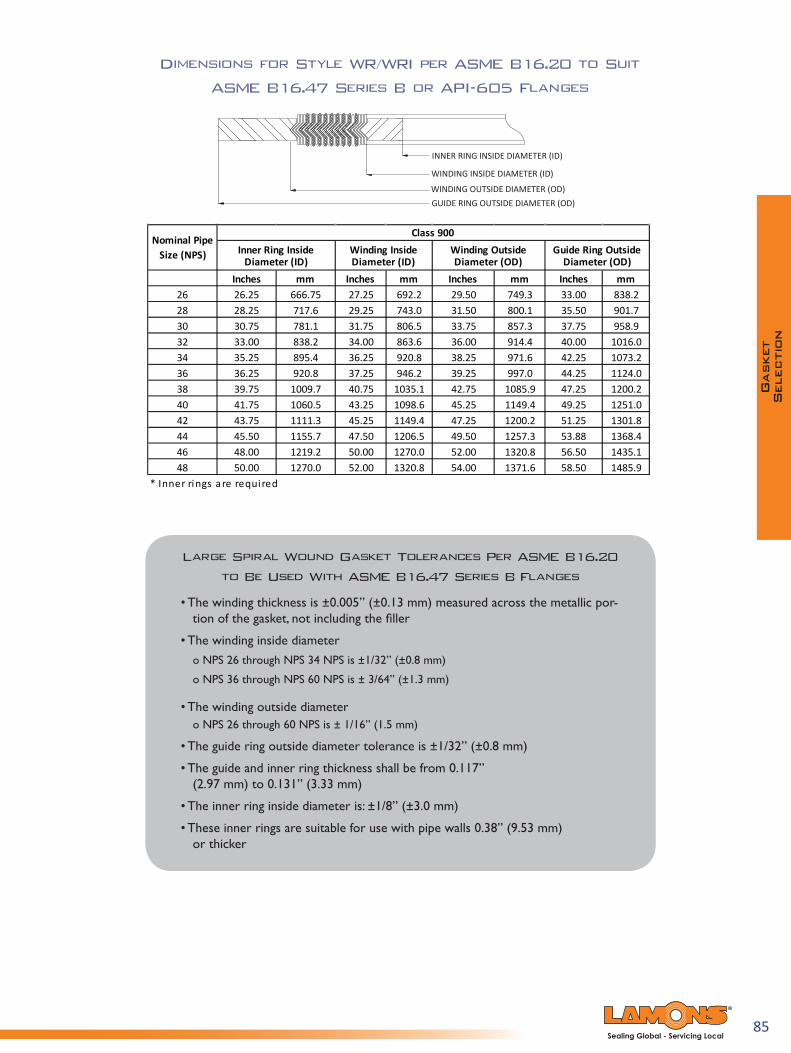
85Sealing Global - Servicing Local
Large Spiral Wound Gasket Tolerances Per ASME B16.20 to Be Used With ASME B16.47 Series B Flanges
• The winding thickness is ±0.005” (±0.13 mm) measured across the metallic por-tion of the gasket, not including the filler
• The winding inside diameter o NPS 26 through NPS 34 NPS is ±1/32” (±0.8 mm)
o NPS 36 through NPS 60 NPS is ± 3/64” (±1.3 mm)
• The winding outside diameter o NPS 26 through 60 NPS is ± 1/16” (1.5 mm)
• The guide ring outside diameter tolerance is ±1/32” (±0.8 mm)
• The guide and inner ring thickness shall be from 0.117” (2.97 mm) to 0.131” (3.33 mm)
• The inner ring inside diameter is: ±1/8” (±3.0 mm)
• These inner rings are suitable for use with pipe walls 0.38” (9.53 mm) or thicker
Dimensions for Style WR/WRI per ASME B16.20 to Suit
ASME B16.47 Series B or API-605 Flanges
INNER RING INSIDE DIAMETER (ID)
WINDING INSIDE DIAMETER (ID)
WINDING OUTSIDE DIAMETER (OD)GUIDE RING OUTSIDE DIAMETER (OD)
Inches mm Inches mm Inches mm Inches mm26 26.25 666.75 27.25 692.2 29.50 749.3 33.00 838.228 28.25 717.6 29.25 743.0 31.50 800.1 35.50 901.730 30.75 781.1 31.75 806.5 33.75 857.3 37.75 958.932 33.00 838.2 34.00 863.6 36.00 914.4 40.00 1016.034 35.25 895.4 36.25 920.8 38.25 971.6 42.25 1073.236 36.25 920.8 37.25 946.2 39.25 997.0 44.25 1124.038 39.75 1009.7 40.75 1035.1 42.75 1085.9 47.25 1200.240 41.75 1060.5 43.25 1098.6 45.25 1149.4 49.25 1251.042 43.75 1111.3 45.25 1149.4 47.25 1200.2 51.25 1301.844 45.50 1155.7 47.50 1206.5 49.50 1257.3 53.88 1368.446 48.00 1219.2 50.00 1270.0 52.00 1320.8 56.50 1435.148 50.00 1270.0 52.00 1320.8 54.00 1371.6 58.50 1485.9
* Inner rings are required
Nominal Pipe Size (NPS)
Class 900Inner Ring Inside
Diameter (ID)Winding Outside Diameter (OD)
Guide Ring Outside Diameter (OD)
Winding Inside Diameter (ID)
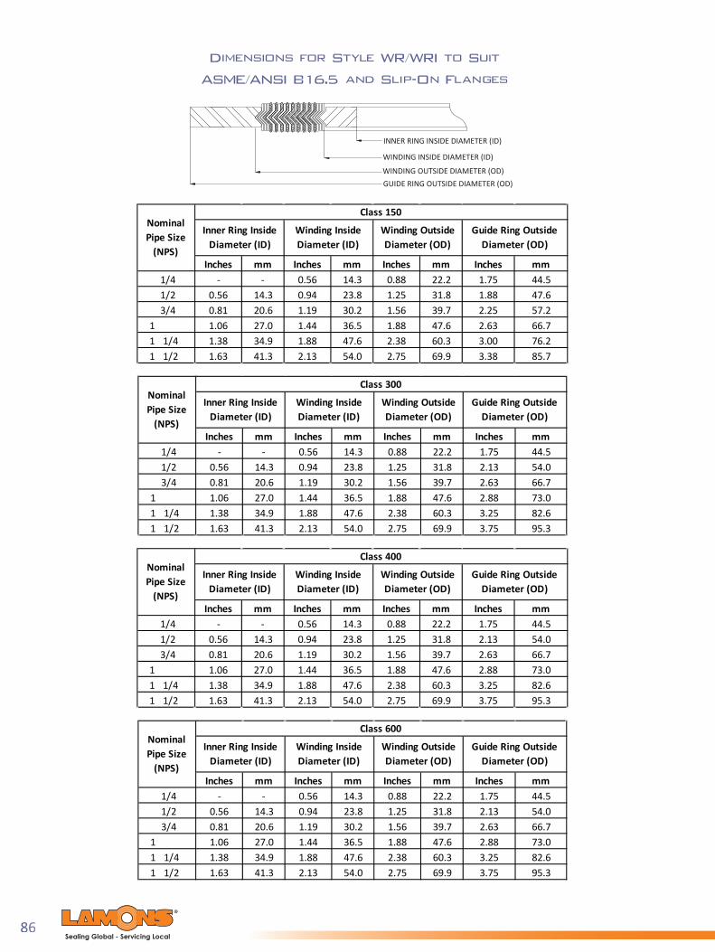
86Sealing Global - Servicing Local
Dimensions for Style WR/WRI to Suit
ASME/ANSI B16.5 and Slip-On Flanges
INNER RING INSIDE DIAMETER (ID)
WINDING INSIDE DIAMETER (ID)
WINDING OUTSIDE DIAMETER (OD)GUIDE RING OUTSIDE DIAMETER (OD)
Inches mm Inches mm Inches mm Inches mm1/4 - - 0.56 14.3 0.88 22.2 1.75 44.51/2 0.56 14.3 0.94 23.8 1.25 31.8 1.88 47.63/4 0.81 20.6 1.19 30.2 1.56 39.7 2.25 57.2
1 1.06 27.0 1.44 36.5 1.88 47.6 2.63 66.71 1/4 1.38 34.9 1.88 47.6 2.38 60.3 3.00 76.21 1/2 1.63 41.3 2.13 54.0 2.75 69.9 3.38 85.7
Winding Inside Diameter (ID)
Winding Outside Diameter (OD)
Guide Ring Outside Diameter (OD)
Nominal Pipe Size
(NPS)
Class 150
Inner Ring Inside Diameter (ID)
Inches mm Inches mm Inches mm Inches mm1/4 - - 0.56 14.3 0.88 22.2 1.75 44.51/2 0.56 14.3 0.94 23.8 1.25 31.8 2.13 54.03/4 0.81 20.6 1.19 30.2 1.56 39.7 2.63 66.7
1 1.06 27.0 1.44 36.5 1.88 47.6 2.88 73.01 1/4 1.38 34.9 1.88 47.6 2.38 60.3 3.25 82.61 1/2 1.63 41.3 2.13 54.0 2.75 69.9 3.75 95.3
Winding Outside Diameter (OD)
Guide Ring Outside Diameter (OD)
Class 400
Inner Ring Inside Diameter (ID)
Winding Inside Diameter (ID)
Nominal Pipe Size
(NPS)
Inches mm Inches mm Inches mm Inches mm1/4 - - 0.56 14.3 0.88 22.2 1.75 44.51/2 0.56 14.3 0.94 23.8 1.25 31.8 2.13 54.03/4 0.81 20.6 1.19 30.2 1.56 39.7 2.63 66.7
1 1.06 27.0 1.44 36.5 1.88 47.6 2.88 73.01 1/4 1.38 34.9 1.88 47.6 2.38 60.3 3.25 82.61 1/2 1.63 41.3 2.13 54.0 2.75 69.9 3.75 95.3
Winding Inside Diameter (ID)
Winding Outside Diameter (OD)
Guide Ring Outside Diameter (OD)
Inner Ring Inside Diameter (ID)
Class 300Nominal Pipe Size
(NPS)
Inches mm Inches mm Inches mm Inches mm1/4 - - 0.56 14.3 0.88 22.2 1.75 44.51/2 0.56 14.3 0.94 23.8 1.25 31.8 2.13 54.03/4 0.81 20.6 1.19 30.2 1.56 39.7 2.63 66.7
1 1.06 27.0 1.44 36.5 1.88 47.6 2.88 73.01 1/4 1.38 34.9 1.88 47.6 2.38 60.3 3.25 82.61 1/2 1.63 41.3 2.13 54.0 2.75 69.9 3.75 95.3
Class 600
Inner Ring Inside Diameter (ID)
Winding Inside Diameter (ID)
Winding Outside Diameter (OD)
Guide Ring Outside Diameter (OD)
Nominal Pipe Size
(NPS)

87Sealing Global - Servicing Local
Dimensions for Style WR/WRI to Suit
ASME/ANSI B16.5 and Slip-On Flanges
INNER RING INSIDE DIAMETER (ID)
WINDING INSIDE DIAMETER (ID)
WINDING OUTSIDE DIAMETER (OD)GUIDE RING OUTSIDE DIAMETER (OD)
Standard spiral wound gasket dimensions are not compatible with slip-on flanges, threaded flange, or lap joint flanges in certain sizes due to the larger bore on slip-on flanges.
Inches mm Inches mm Inches mm Inches mm1/2 0.56 14.3 0.94 23.8 1.25 31.8 2.50 63.53/4 0.81 20.6 1.19 30.2 1.56 39.7 2.75 69.9
1 1.06 27.0 1.44 36.5 1.88 47.6 3.13 79.41 1/4 1.38 34.9 1.88 47.6 2.38 60.3 3.50 88.91 1/2 1.63 41.3 2.13 54.0 2.75 69.9 3.88 98.4
Class 900
Inner Ring Inside Diameter (ID)
Winding Inside Diameter (ID)
Winding Outside Diameter (OD)
Guide Ring Outside Diameter (OD)
Nominal Pipe Size
(NPS)
Inches mm Inches mm Inches mm Inches mm1/2 0.56 14.3 0.94 23.8 1.25 31.8 2.50 63.53/4 0.81 20.6 1.19 30.2 1.56 39.7 2.75 69.9
1 1.06 27.0 1.44 36.5 1.88 47.6 3.13 79.41 1/4 1.38 34.9 1.88 47.6 2.38 60.3 3.50 88.91 1/2 1.63 41.3 2.13 54.0 2.75 69.9 3.88 98.4
Class 1500
Inner Ring Inside Diameter (ID)
Winding Inside Diameter (ID)
Winding Outside Diameter (OD)
Guide Ring Outside Diameter (OD)
Nominal Pipe Size
(NPS)

88Sealing Global - Servicing Local
Dimensions for Style WR/WRI to Suit Type A and B
Flange Facings per EN 1514-2 (Inches)
INNER RING INSIDE DIAMETER (ID)
WINDING INSIDE DIAMETER (ID)
WINDING OUTSIDE DIAMETER (OD)GUIDE RING OUTSIDE DIAMETER (OD)
PN10 PN25 PN40 PN63 PN100 PN160
mm Inches Inches10 0.709 0.94515 0.906 1.14220 1.102 1.33925 1.378 1.61432 1.693 1.92940 1.969 2.20550 2.402 2.756 4.44965 3.031 3.386 5.39480 3.543 3.898 5.827
100 4.528 5.000 6.378 6.850125 5.512 5.984 7.559 8.268150 6.575 7.047 8.543 9.724200 8.504 8.976 10.709 11.181 11.417 12.165250 10.512 10.984 12.874 13.386 13.858 14.331 15.394 15.276300 12.520 12.992 14.842 15.748 16.417 16.693 18.031 18.031350 14.173 14.803 17.205 17.992 18.661 19.134 20.157 -400 16.142 16.614 19.213 20.236 21.496 21.378 22.520 -500 20.079 20.551 23.346 24.567 24.724 25.866 27.716 -600 24.016 24.488 27.362 28.779 29.409 30.079 32.008 -700 27.953 28.425 31.890 32.795 33.543 34.606 37.402 -800 31.890 32.677 36.102 37.087 38.346 38.898 - -900 35.827 36.614 40.039 41.024 42.677 43.622 - -
1000 39.764 40.551 44.252 45.433 47.008 - - -
1.339 1.339 2.2051.811
Guide Ring Outside Diameter (OD)Winding Outside Diameter (OD)
Inches
1.811 -1.535 1.535
2.087 2.087
21.654
4.016 4.1734.528 4.685
6.772 6.929
13.93715.748
2.677 2.6773.386
17.717
3.386
12.75611.929 12.087
7.835 7.9929.764 9.921
5.630 5.7876.0637.0878.543
10.118
5.591
2.0082.4022.795
5.000
2.402-
3.228-
4.0554.6855.630
3.2283.6224.213
PN10, PN25,PN40
PN63, PN100, PN160
Winding Outside Diameter (OD)
Inches Inches
2.402 -
25.59129.76434.01637.95342.283
14.09415.90517.95321.89025.82730.00034.25238.18942.520
6.6147.6388.819
Inner ring Inside
Diameter (ID)
Winding Inside
Diameter (ID)
DN

89Sealing Global - Servicing Local
Dimensions for Style WR/WRI to Suit Type A and B
Flange Facings per EN 1514-2 (Millimeters)
INNER RING INSIDE DIAMETER (ID)
WINDING INSIDE DIAMETER (ID)
WINDING OUTSIDE DIAMETER (OD)GUIDE RING OUTSIDE DIAMETER (OD)
PN10 PN25 PN40 PN63 PN100 PN160
mm mm mm10 18 2415 23 2920 28 3425 35 4132 43 4940 50 5650 61 70 11365 77 86 13780 90 99 148
100 115 127 162 174125 140 152 192 210150 167 179 217 247200 216 228 272 284 290 309250 267 279 327 340 352 364 391 388300 318 330 377 400 417 424 458 458350 360 376 437 457 474 486 512 -400 410 422 488 514 546 543 572 -500 510 522 593 624 628 657 704 -600 610 622 695 731 747 764 813 -700 710 722 810 833 852 879 950 -800 810 830 917 942 974 988 - -900 910 930 1017 1042 1084 1108 - -
1000 1010 1030 1124 1154 1194 - - -
6156
Winding Outside Diameter (OD)
Guide Ring Outside Diameter (OD)
PN63, PN100, PN160
mm
103-
82-
mm
154115143119
168 180143 147194 217172 176224 257199 203
324248303
252307
354400
358404
450550
456556
650756
656762
864964
870970
616886
102
34394653
1074
3439-
53-
6886
106119
1080
465161718292
107127142
mm
DNPN10, PN25,
PN40
Inner ring Inside
Diameter (ID)
Winding Inside
Diameter (ID)
Winding Outside Diameter (OD)

90Sealing Global - Servicing Local
Dimensions for Style WR to Suit British Standard BS 10
Welded Neck & Slip-On Flanges Table D and E (Millimeters)
WINDING INSIDE DIAMETER (ID)
WINDING OUTSIDE DIAMETER (OD)GUIDE RING OUTSIDE DIAMETER (OD)
TABLED
TABLEE
1/2 26.2 37.3 54.0 54.03/4 31.8 42.9 60.3 60.3
1 39.7 52.4 69.9 69.91 1/4 47.6 60.3 74.6 74.61 1/2 54.0 66.7 85.8 85.82 66.7 79.4 98.5 98.52 1/2 82.6 98.5 111.2 111.23 96.9 112.8 130.2 130.23 1/2 109.6 125.5 149.3 149.34 123.9 139.7 161.9 161.94 1/2 136.6 152.4 174.6 174.65 149.2 165.1 193.6 193.66 174.6 190.5 219.0 215.97 200.0 219.0 244.5 241.38 225.4 244.5 276.2 273.09 250.8 269.9 308.0 304.8
10 276.3 295.3 336.6 336.611 301.6 320.7 362.0 362.012 327.0 349.3 387.4 384.213 368.3 390.6 419.1 415.914 393.7 416.0 447.7 447.715 419.1 441.3 473.0 473.016 444.5 466.7 498.5 498.517 473.0 498.5 530.3 527.018 498.5 523.9 562.0 562.019 523.9 549.3 587.4 587.420 549.3 574.7 619.2 619.221 574.7 603.3 651.0 647.722 600.0 628.7 673.1 673.123 625.5 654.0 698.5 698.524 650.9 679.5 730.3 728.7
Winding Inside Diameter (ID)
NominalPipe Size
(NPS)
Guide Ring Outside Diameter (OD)Winding Outside
Diameter (OD)
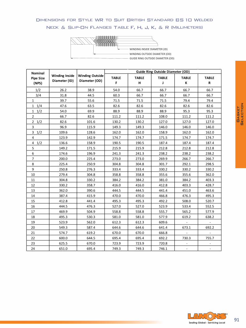
91Sealing Global - Servicing Local
Dimensions for Style WR to Suit British Standard BS 10 Welded
Neck & Slip-On Flanges Table F, H, J, K, & R (Millimeters)
WINDING INSIDE DIAMETER (ID)
WINDING OUTSIDE DIAMETER (OD)GUIDE RING OUTSIDE DIAMETER (OD)
1/2 26.2 38.9 54.0 66.7 66.7 66.7 66.73/4 31.8 44.5 60.3 66.7 66.7 66.7 66.7
1 39.7 55.6 71.5 71.5 71.5 79.4 79.41 1/4 47.6 63.5 82.6 82.6 82.6 82.6 82.61 1/2 54.0 69.9 88.9 88.9 88.9 95.3 95.32 66.7 82.6 111.2 111.2 108.0 111.2 111.22 1/2 82.6 101.6 130.2 130.2 127.0 127.0 127.03 96.9 115.9 149.3 149.3 146.0 146.0 146.03 1/2 109.6 128.6 162.0 162.0 158.9 162.0 162.04 123.9 142.9 174.7 174.7 171.5 174.7 174.74 1/2 136.6 158.9 190.5 190.5 187.4 187.4 187.45 149.2 171.5 215.9 215.9 212.8 212.8 212.86 174.6 196.9 241.3 241.3 238.2 238.2 238.27 200.0 225.4 273.0 273.0 269.9 266.7 266.78 225.4 250.9 304.8 304.8 301.7 292.1 298.59 250.8 276.3 333.4 333.4 330.2 330.2 330.2
10 279.4 304.8 358.8 358.8 355.6 355.6 362.011 304.8 330.2 384.2 384.2 381.0 384.2 403.312 330.2 358.7 416.0 416.0 412.8 403.3 428.713 362.0 390.6 444.5 444.5 441.4 451.0 463.614 387.4 415.9 470.0 470.0 466.8 476.3 495.315 412.8 441.4 495.3 495.3 492.2 508.0 520.716 444.5 476.3 527.0 527.0 523.9 533.4 552.517 469.9 504.9 558.8 558.8 555.7 565.2 577.918 495.3 530.3 581.0 581.0 577.9 619.2 638.219 523.9 562.0 612.3 612.3 609.6 - -20 549.3 587.4 644.6 644.6 641.4 673.1 692.221 574.7 619.2 670.0 670.0 666.8 - -22 600.0 644.5 695.4 695.4 692.2 730.3 755.723 625.5 670.0 723.9 723.9 720.8 - -24 651.0 695.4 749.3 749.3 746.1 - -
Guide Ring Outside Diameter (OD)Winding Inside Diameter (ID)
Winding Outside Diameter (OD)
NominalPipe Size
(NPS) TABLE
KTABLE
FTABLE
RTABLE
HTABLE
J

92Sealing Global - Servicing Local
Dimensions for Style WR to Suit British Standard BS 10
Welded Neck & Slip-On Flanges Table S (Millimeters)
WINDING INSIDE DIAMETER (ID)
WINDING OUTSIDE DIAMETER (OD)GUIDE RING OUTSIDE DIAMETER (OD)
19.1 31.8 19.1 31.8 69.925.4 39.7 25.4 39.7 69.9
1 31.8 47.6 31.8 47.6 82.6
1 1/4 38.1 55.6 38.1 55.6 88.9
1 1/2 44.5 63.5 44.5 63.5 101.6
2 57.2 76.2 57.2 79.4 114.3
2 1/2 69.9 88.9 73.0 95.3 127.0
3 82.6 101.6 85.7 108.0 142.9
3 1/2 95.3 114.3 98.4 120.7 168.3
4 108.0 127.0 111.1 136.5 177.8
4 1/2 120.7 139.7 123.8 149.2 190.5
5 133.4 152.4 136.5 161.9 212.7
6 158.8 177.8 161.9 187.3 247.7
7 187.3 209.6 187.3 219.1 288.9
8 212.7 235.0 212.7 244.5 323.9
9 238.1 260.4 241.3 273.1 358.8
10 263.5 285.8 266.7 301.6 393.7
288.9 317.5 292.1 327.0 435.0
314.3 346.1 320.7 355.6 469.9
339.7 371.5 346.1 384.2 501.7
365.1 400.1 371.5 409.6 539.8390.5 428.6 400.1 438.2 581.0415.9 454.0 425.5 466.7 616.0
Guide Ring Outside Diameter (OD)Winding Outside
Diameter (OD)Winding Inside Diameter (ID)
Winding Inside Diameter (ID)
Winding Outside Diameter (OD)
BS 10: 1931 BS 10: 1962
Nominal Pipe Size (NPS)
11 (12) 3/4 O/D Pipe
12 (14) 3/4 O/D Pipe
13 (15) 3/4 O/D Pipe
14 (16) 3/4 O/D Pipe 15 (17) 3/4 O/D Pipe 16 (18) 3/4 O/D Pipe
1/23/4

93Sealing Global - Servicing Local
Dimensions for Style WR/WRI per British BS 3381 to Suit
BS 1560 and ASME/ANSI B16.5 Flanges (Millimeters)
INNER RING INSIDE DIAMETER (ID)
WINDING INSIDE DIAMETER (ID)
WINDING OUTSIDE DIAMETER (OD)GUIDE RING OUTSIDE DIAMETER (OD)
1/2 14.3 54.03/4 20.6 66.7
1 27.0 73.01 1/4 34.9 82.61 1/2 41.3 95.32 52.4 111.12 1/2 63.5 130.23 77.8 149.24 103.2 181.05 128.5 215.96 154.0 250.88 203.2 308.0
10 254.0 362.012 303.2 422.314 342.9 485.816 393.7 539.818 444.5 596.920 495.3 654.124 596.9
32.240.148.060.770.386.198.8
121.1149.6178.2210.0263.9317.9375.1406.8464.0527.5578.3686.2
18.725.031.444.150.466.379.094.9
120.3147.2174.2225.0280.6333.0364.7415.5469.5520.3625.1 774.7
Guide Ring Outside Diameter (OD)
1/2 14.3 18.7 32.2 47.63/4 20.6 26.6 40.1 57.2
1 27.0 32.9 48.0 66.71 1/4 34.9 45.6 60.7 76.21 1/2 41.3 53.6 70.3 85.72 52.4 69.5 86.1 104.82 1/2 63.5 82.2 98.8 123.83 77.8 101.2 121.1 136.54 103.2 126.6 149.6 174.65 128.5 153.6 178.2 196.96 154.0 180.6 210.0 222.38 203.2 231.4 263.9 279.4
10 254.0 286.9 317.9 339.712 303.2 339.3 375.1 409.614 342.9 371.1 406.8 450.916 393.7 421.9 464.0 514.418 444.5 475.9 527.5 549.320 495.3 526.7 578.3 606.424 596.9 631.4 686.2 717.6
Class 150
Winding Outside Diameter (OD)
Winding Inside Diameter (ID)
Guide Ring Outside Diameter (OD)
Nominal Pipe Size (NPS)
Inner Ring Inside Diameter (ID)
Class 300Inner Ring Inside
Diameter (ID)Winding Inside Diameter (ID)
Winding Outside Diameter (OD)
Nominal Pipe Size (NPS)
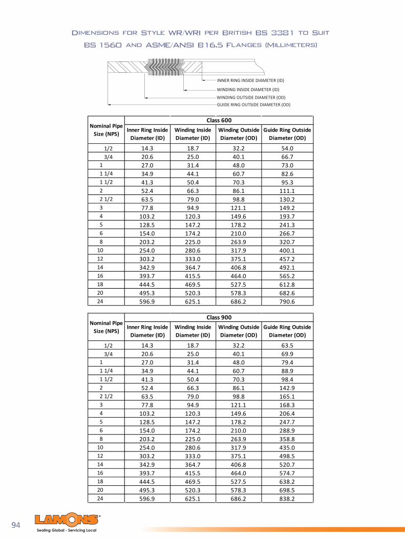
94Sealing Global - Servicing Local
Dimensions for Style WR/WRI per British BS 3381 to Suit
BS 1560 and ASME/ANSI B16.5 Flanges (Millimeters)
1/2 14.3 18.7 32.2 54.03/4 20.6 25.0 40.1 66.7
1 27.0 31.4 48.0 73.01 1/4 34.9 44.1 60.7 82.61 1/2 41.3 50.4 70.3 95.32 52.4 66.3 86.1 111.12 1/2 63.5 79.0 98.8 130.23 77.8 94.9 121.1 149.24 103.2 120.3 149.6 193.75 128.5 147.2 178.2 241.36 154.0 174.2 210.0 266.78 203.2 225.0 263.9 320.7
10 254.0 280.6 317.9 400.112 303.2 333.0 375.1 457.214 342.9 364.7 406.8 492.116 393.7 415.5 464.0 565.218 444.5 469.5 527.5 612.820 495.3 520.3 578.3 682.624 596.9 625.1 686.2 790.6
Class 600Inner Ring Inside
Diameter (ID)Winding Inside Diameter (ID)
Guide Ring Outside Diameter (OD)
Nominal Pipe Size (NPS)
Winding Outside Diameter (OD)
1/2 14.3 18.7 32.2 63.53/4 20.6 25.0 40.1 69.9
1 27.0 31.4 48.0 79.41 1/4 34.9 44.1 60.7 88.91 1/2 41.3 50.4 70.3 98.42 52.4 66.3 86.1 142.92 1/2 63.5 79.0 98.8 165.13 77.8 94.9 121.1 168.34 103.2 120.3 149.6 206.45 128.5 147.2 178.2 247.76 154.0 174.2 210.0 288.98 203.2 225.0 263.9 358.8
10 254.0 280.6 317.9 435.012 303.2 333.0 375.1 498.514 342.9 364.7 406.8 520.716 393.7 415.5 464.0 574.718 444.5 469.5 527.5 638.220 495.3 520.3 578.3 698.524 596.9 625.1 686.2 838.2
Class 900Winding Outside Diameter (OD)
Guide Ring Outside Diameter (OD)
Nominal Pipe Size (NPS)
Inner Ring Inside Diameter (ID)
Winding Inside Diameter (ID)
INNER RING INSIDE DIAMETER (ID)
WINDING INSIDE DIAMETER (ID)
WINDING OUTSIDE DIAMETER (OD)GUIDE RING OUTSIDE DIAMETER (OD)

95Sealing Global - Servicing Local
Dimensions for Style WR/WRI per British BS 3381 to Suit
BS 1560 and ASME/ANSI B16.5 Flanges (Millimeters)
1/2 14.3 18.7 32.2 63.53/4 20.6 25.0 40.1 69.9
1 27.0 31.4 48.0 79.41 1/4 34.9 44.1 60.7 88.91 1/2 41.3 50.4 70.3 98.42 52.4 66.3 86.1 142.92 1/2 63.5 79.0 98.8 165.13 77.8 94.9 121.1 174.64 103.2 120.3 149.6 209.65 128.5 147.2 178.2 254.06 154.0 174.2 210.0 282.68 203.2 225.0 263.9 352.4
10 254.0 280.6 317.9 435.012 303.2 333.0 375.1 520.714 342.9 364.7 406.8 577.916 393.7 415.5 464.0 641.418 444.5 469.5 527.5 704.920 495.3 520.3 578.3 755.724 596.9 625.1 686.2 901.7
Inner Ring Inside Diameter (ID)
Winding Inside Diameter (ID)
Winding Outside Diameter (OD)
Class 1500Guide Ring Outside
Diameter (OD)
Nominal Pipe Size (NPS)
1/2 14.3 18.7 32.2 69.93/4 20.6 25.0 40.1 76.2
1 27.0 31.4 48.0 85.71 1/4 34.9 39.3 60.7 104.81 1/2 41.3 47.2 70.3 117.52 52.4 58.3 86.1 146.12 1/2 63.5 69.5 98.8 168.33 77.8 91.7 121.1 196.94 103.2 117.1 149.6 235.05 128.5 142.5 178.2 279.46 154.0 171.1 210.0 317.58 203.2 215.5 263.9 387.4
10 254.0 269.5 317.9 476.312 303.2 323.5 375.1 549.6
Class 2500Guide Ring Outside
Diameter (OD)Inner Ring Inside
Diameter (ID)
Nominal Pipe Size (NPS)
Winding Inside Diameter (ID)
Winding Outside Diameter (OD)
INNER RING INSIDE DIAMETER (ID)
WINDING INSIDE DIAMETER (ID)
WINDING OUTSIDE DIAMETER (OD)GUIDE RING OUTSIDE DIAMETER (OD)
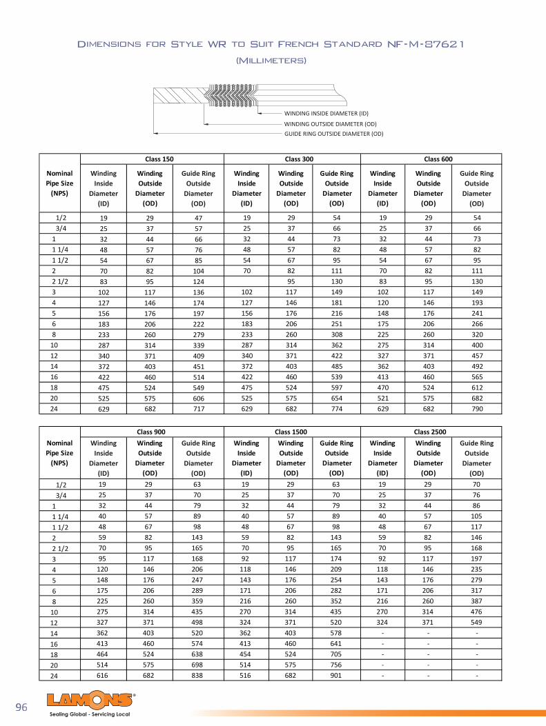
96Sealing Global - Servicing Local
Dimensions for Style WR to Suit French Standard NF-M-87621
(Millimeters)
WINDING INSIDE DIAMETER (ID)
WINDING OUTSIDE DIAMETER (OD)GUIDE RING OUTSIDE DIAMETER (OD)
1/2 19 29 47 19 29 54 19 29 543/4 25 37 57 25 37 66 25 37 66
1 32 44 66 32 44 73 32 44 731 1/4 48 57 76 48 57 82 48 57 821 1/2 54 67 85 54 67 95 54 67 952 70 82 104 70 82 111 70 82 1112 1/2 83 95 124 95 130 83 95 1303 102 117 136 102 117 149 102 117 1494 127 146 174 127 146 181 120 146 1935 156 176 197 156 176 216 148 176 2416 183 206 222 183 206 251 175 206 2668 233 260 279 233 260 308 225 260 320
10 287 314 339 287 314 362 275 314 40012 340 371 409 340 371 422 327 371 45714 372 403 451 372 403 485 362 403 49216 422 460 514 422 460 539 413 460 56518 475 524 549 475 524 597 470 524 61220 525 575 606 525 575 654 521 575 68224 629 682 717 629 682 774 629 682 790
1/2 19 29 63 19 29 63 19 29 703/4 25 37 70 25 37 70 25 37 76
1 32 44 79 32 44 79 32 44 861 1/4 40 57 89 40 57 89 40 57 1051 1/2 48 67 98 48 67 98 48 67 1172 59 82 143 59 82 143 59 82 1462 1/2 70 95 165 70 95 165 70 95 1683 95 117 168 92 117 174 92 117 1974 120 146 206 118 146 209 118 146 2355 148 176 247 143 176 254 143 176 2796 175 206 289 171 206 282 171 206 3178 225 260 359 216 260 352 216 260 387
10 275 314 435 270 314 435 270 314 47612 327 371 498 324 371 520 324 371 54914 362 403 520 362 403 578 - - -16 413 460 574 413 460 641 - - -18 464 524 638 454 524 705 - - -20 514 575 698 514 575 756 - - -24 616 682 838 516 682 901 - - -
Winding Outside
Diameter (OD)
Class 600
Class 900
Class 150 Class 300
Class 1500 Class 2500
Winding Outside
Diameter (OD)
Winding Outside
Diameter (OD)
Winding Outside
Diameter (OD)
Guide Ring Outside
Diameter (OD)
Winding Inside
Diameter (ID)
Winding Inside
Diameter (ID)
Nominal Pipe Size
(NPS)
Winding Outside
Diameter (OD)
Winding Inside
Diameter (ID)
Winding Outside
Diameter (OD)
Guide Ring Outside
Diameter (OD)
Winding Inside
Diameter (ID)
Nominal Pipe Size
(NPS)
Guide RingOutside
Diameter(OD)
Guide RingOutside
Diameter(OD)
Guide RingOutside
Diameter(OD)
Guide RingOutside
Diameter(OD)
WindingInside
Diameter(ID)
WindingInside
Diameter(ID)

97Sealing Global - Servicing Local
Dimensions for Style WR to Suit Japanese (JIS) Flanges
Pressure Rating 10 kgf/cm2
WINDING INSIDE DIAMETER (ID)
WINDING OUTSIDE DIAMETER (OD)GUIDE RING OUTSIDE DIAMETER (OD)
DN
Inches mm Inches mm Inches mm10 0.945 24 1.457 37 2.047 5215 1.102 28 1.614 41 2.244 5720 1.339 34 1.850 47 2.441 6225 1.575 40 2.087 53 2.913 7432 2.008 51 2.638 67 3.307 8440 2.244 57 2.874 73 3.504 8950 2.717 69 3.504 89 4.094 10465 3.425 87 4.213 107 4.882 12480 3.858 98 4.646 118 5.276 13490 4.331 110 5.118 130 5.669 144
100 4.843 123 5.630 143 6.260 159125 5.827 148 6.811 173 7.480 190150 6.850 174 7.835 199 8.661 220175 7.913 201 8.898 226 9.646 245200 8.937 227 9.921 252 6.693 170225 9.921 252 10.906 277 11.417 290250 10.945 278 12.205 310 13.071 332300 12.953 329 14.213 361 14.843 377350 14.409 366 15.984 406 16.614 422400 16.417 417 17.992 457 19.055 484450 18.425 468 20.394 518 21.220 539500 20.394 518 22.362 568 23.386 594550 22.402 569 24.370 619 25.591 650600 24.409 620 26.378 670 27.559 700
Winding Outside Diameter (OD)
Guide Ring Outside Diameter (OD)
Winding Inside Diameter (ID)
10.629 270

98Sealing Global - Servicing Local
INNER RING INSIDE DIAMETER (ID)
WINDING INSIDE DIAMETER (ID)
WINDING OUTSIDE DIAMETER (OD)GUIDE RING OUTSIDE DIAMETER (OD)
Dimensions for Style WR to Suit Japanese (JIS) Flanges
Pressure Rating 16-20 kgf/cm2
DN
Inches mm Inches mm Inches mm Inches mm10 0.709 18 0.945 24 1.457 37 2.047 5215 0.866 22 1.102 28 1.614 41 2.244 5720 1.102 28 1.339 34 1.850 47 2.441 6225 1.339 34 1.575 40 2.087 53 2.913 7432 1.693 43 2.008 51 2.638 67 3.307 8440 1.929 49 2.244 57 2.874 73 3.504 8950 2.402 61 2.717 69 3.504 89 4.094 10465 3.031 77 3.425 87 4.213 107 4.882 12480 3.504 89 3.898 99 4.685 119 5.512 14090 4.016 102 4.488 114 5.472 139 5.906 150
100 4.528 115 5.000 127 5.984 152 6.496 165125 5.512 140 5.984 152 6.969 177 7.953 202150 6.535 166 7.165 182 8.425 214 9.331 237175 - - - - - - - -200 8.543 217 9.173 233 10.433 265 11.102 282225 - - - - - - - -250 10.551 268 11.339 288 12.913 328 13.937 354300 12.559 319 13.346 339 14.921 379 15.906 404350 14.016 356 14.803 376 16.378 416 17.717 450400 16.024 407 17.008 432 18.976 482 20.000 508450 18.031 458 19.016 483 20.984 533 22.559 573500 20.000 508 20.984 533 22.953 583 24.724 628550 22.008 559 22.992 584 24.961 634 26.929 684600 24.016 610 25.000 635 26.969 685 28.898 734
Inner Ring Inside Diameter (ID)
Winding Inside Diameter (ID)
Winding Outside Diameter (OD)
Guide Ring Outside Diameter (OD)

99Sealing Global - Servicing Local
INNER RING INSIDE DIAMETER (ID)
WINDING INSIDE DIAMETER (ID)
WINDING OUTSIDE DIAMETER (OD)GUIDE RING OUTSIDE DIAMETER (OD)
Dimensions for Style WR to Suit Japanese (JIS) Flanges
Pressure Rating 30 kgf/cm2
Dimensions for Style WR to Suit Japanese (JIS) Flanges
Pressure Rating 40 kgf/cm2
DN
Inches mm Inches mm Inches mm Inches mm10 0.591 15 0.827 21 1.339 34 2.323 5915 0.709 18 0.945 24 1.457 37 2.520 6420 0.906 23 1.142 29 1.654 42 2.717 6925 1.142 29 1.378 35 1.890 48 3.110 7932 1.496 38 1.732 44 2.362 60 3.504 8940 1.693 43 2.008 51 2.638 67 3.937 10050 2.165 55 2.480 63 3.110 79 4.488 11465 2.677 68 3.071 78 3.858 98 5.512 14080 3.150 80 3.543 90 4.331 110 5.906 15090 3.622 92 4.016 102 5.000 127 6.378 162
100 4.094 104 4.567 116 5.551 141 7.165 182125 5.039 128 5.512 140 6.496 165 8.819 224150 6.024 153 6.496 165 7.756 197 10.433 265200 7.953 202 8.583 218 9.843 250 12.402 315250 9.882 251 10.669 271 12.244 311 14.882 378300 11.811 300 12.598 320 14.173 360 17.087 434350 13.228 336 14.016 356 15.591 396 18.858 479400 15.079 383 15.866 403 17.835 453 20.906 531
Guide Ring Outside Diameter (OD)
Winding Outside Diameter (OD)
Inner Ring Inside Diameter (ID)
Winding Inside Diameter (ID)
DN
Inches mm Inches mm Inches mm Inches mm10 0.709 18 0.945 24 1.457 37 2.323 5915 0.866 22 1.102 28 1.614 41 2.520 6420 1.102 28 1.339 34 1.850 47 2.717 6925 1.339 34 1.575 40 2.087 53 3.110 7932 1.693 43 2.008 51 2.638 67 3.504 8940 1.929 49 2.244 57 2.874 73 3.937 10050 2.402 61 2.717 69 3.504 89 4.488 11465 2.677 68 3.071 78 3.858 98 5.512 14080 3.150 80 3.543 90 4.331 110 5.906 15090 3.622 92 4.016 102 5.000 127 6.378 162
100 4.094 104 4.567 116 5.551 141 6.772 172125 5.039 128 5.512 140 6.496 165 8.150 207150 6.024 153 6.496 165 7.756 197 9.803 249200 7.953 202 8.583 218 9.843 250 11.575 294250 9.882 251 10.669 271 12.244 311 14.173 360300 11.811 300 12.598 320 14.173 360 16.457 418350 13.228 336 14.016 356 15.591 396 18.228 463400 15.079 383 15.866 403 17.835 453 20.630 524
Winding Inside Diameter (ID)
Winding Outside Diameter (OD)
Guide Ring Outside Diameter (OD)
Inner Ring Inside Diameter (ID)
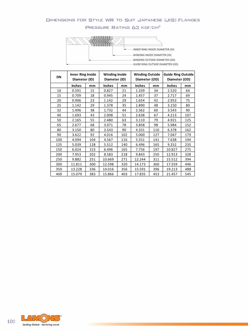
100Sealing Global - Servicing Local
INNER RING INSIDE DIAMETER (ID)
WINDING INSIDE DIAMETER (ID)
WINDING OUTSIDE DIAMETER (OD)GUIDE RING OUTSIDE DIAMETER (OD)
Dimensions for Style WR to Suit Japanese (JIS) Flanges
Pressure Rating 63 kgf/cm2
DN
Inches mm Inches mm Inches mm Inches mm10 0.591 15 0.827 21 1.339 34 2.520 6415 0.709 18 0.945 24 1.457 37 2.717 6920 0.906 23 1.142 29 1.654 42 2.953 7525 1.142 29 1.378 35 1.890 48 3.150 8032 1.496 38 1.732 44 2.362 60 3.543 9040 1.693 43 2.008 51 2.638 67 4.213 10750 2.165 55 2.480 63 3.110 79 4.921 12565 2.677 68 3.071 78 3.858 98 5.984 15280 3.150 80 3.543 90 4.331 110 6.378 16290 3.622 92 4.016 102 5.000 127 7.047 179
100 4.094 104 4.567 116 5.551 141 7.638 194125 5.039 128 5.512 140 6.496 165 9.252 235150 6.024 153 6.496 165 7.756 197 10.827 275200 7.953 202 8.583 218 9.843 250 12.913 328250 9.882 251 10.669 271 12.244 311 15.512 394300 11.811 300 12.598 320 14.173 360 17.559 446350 13.228 336 14.016 356 15.591 396 19.213 488400 15.079 383 15.866 403 17.835 453 21.457 545
Inner Ring Inside Diameter (ID)
Winding Inside Diameter (ID)
Winding Outside Diameter (OD)
Guide Ring Outside Diameter (OD)

101Sealing Global - Servicing Local
Dimensions for Style WR-RJ/WRI-RJ to Suit
Raised Face to RTJ Flanges
INNER RING INSIDE DIAMETER (ID)
WINDING INSIDE DIAMETER (ID)
WINDING OUTSIDE DIAMETER (OD)GUIDE RING OUTSIDE DIAMETER (OD)
Inches mm Inches mm Inches mm Inches mm11 1/4 1.38 34.9 1.81 46.0 3.00 76.21 1/2 1.63 41.3 2.13 54.0 3.38 85.72 2.13 54.0 2.75 69.9 4.13 104.82 1/2 2.75 69.9 3.31 84.1 4.88 123.83 3.31 84.1 3.94 100.0 5.38 136.54 4.31 109.5 5.19 131.8 6.88 174.65 5.31 134.9 6.19 157.2 7.75 196.96 6.31 160.3 7.19 182.6 8.75 222.38 8.25 209.6 9.19 233.4 11.00 279.4
10 10.31 261.9 11.44 290.5 13.38 339.712 12.19 309.6 13.56 344.5 16.13 409.614 13.44 341.3 14.94 379.4 17.75 450.916 15.31 388.9 16.94 430.2 20.25 514.418 17.25 438.2 19.00 482.6 21.63 549.320 19.13 485.8 21.13 536.6 23.88 606.424 23.00 584.2 25.25 641.4 28.25 717.6
Inner Ring Inside Diameter (ID)
Inside Diameter of inner ring will
depend on bore schedule. Please
consult with Lamons Engineering for
proper sizing
Guide Ring Outside Diameter (OD)
Winding Inside Diameter (ID)
Winding Outside Diameter (OD)
Contact Lamons Engineering for Sizes
Class 150
Inches mm Inches mm Inches mm Inches mm1/2 0.56 14.3 0.94 23.8 2.13 54.03/4 0.81 20.6 1.25 31.8 2.63 66.7
1 1.06 27.0 1.56 39.7 2.88 73.01 1/4 1.31 33.3 1.88 47.6 3.25 82.61 1/2 1.56 39.7 2.19 55.6 3.75 95.32 2.13 54.0 2.69 68.3 4.38 111.12 1/2 2.75 69.9 3.31 84.1 5.13 130.23 3.31 84.1 3.94 100.0 5.88 149.24 4.31 109.5 5.19 131.8 7.13 181.05 5.31 134.9 6.44 163.5 8.50 215.96 6.44 163.5 7.63 193.7 9.88 250.88 8.25 209.6 9.94 252.4 12.13 308.0
10 10.31 261.9 12.00 304.8 14.25 362.012 12.88 327.0 14.25 362.0 16.63 422.314 14.25 362.0 15.75 400.1 19.13 485.816 16.25 412.8 17.75 450.9 21.25 539.818 18.25 463.6 20.25 514.4 23.50 596.920 20.25 514.4 22.19 563.6 25.75 654.124 24.25 616.0 26.31 668.3 30.50 774.7
Inside Diameter of inner ring will
depend on bore schedule. Please
consult with Lamons Engineering for
proper sizing
Winding Inside Diameter (ID)
Winding Outside Diameter (OD)
Guide Ring Outside Diameter (OD)
Inner Ring Inside Diameter (ID)
Class 300
NominalPipe Size
(NPS)
NominalPipe Size
(NPS)

102Sealing Global - Servicing Local
Dimensions for Style WR-RJ/WRI-RJ to Suit
Raised Face to RTJ Flanges
INNER RING INSIDE DIAMETER (ID)
WINDING INSIDE DIAMETER (ID)
WINDING OUTSIDE DIAMETER (OD)GUIDE RING OUTSIDE DIAMETER (OD)
Inches mm Inches mm Inches mm Inches mm1/2 0.56 14.3 0.94 23.8 2.13 54.03/4 0.81 20.6 1.25 31.8 2.63 66.7
1 1.06 27.0 1.56 39.7 2.88 73.01 1/4 1.31 33.3 1.88 47.6 3.25 82.61 1/2 1.56 39.7 2.19 55.6 3.75 95.32 2.13 54.0 2.69 68.3 4.38 111.12 1/2 2.75 69.9 3.31 84.1 5.13 130.23 3.31 84.1 3.94 100.0 5.88 149.24 4.31 109.5 5.19 131.8 7.63 193.75 5.31 134.9 6.44 163.5 9.50 241.36 6.44 163.5 7.63 193.7 10.50 266.78 8.25 209.6 9.94 252.4 12.63 320.7
10 10.31 261.9 12.00 304.8 15.75 400.112 12.88 327.0 14.25 362.0 18.00 457.214 14.25 362.0 15.75 400.1 19.38 492.116 16.25 412.8 17.75 450.9 22.25 565.218 18.25 463.6 20.25 514.4 24.13 612.820 20.25 514.4 22.19 563.6 26.88 682.624 24.25 616.0 26.31 668.3 31.13 790.6
Inside Diameter of inner ring will
depend on bore schedule. Please
consult with Lamons Engineering for
proper sizing
Guide Ring Outside Diameter (OD)
Class 600Inner Ring Inside
Diameter (ID)Winding Inside Diameter (ID)
Winding Outside Diameter (OD)
Inches mm Inches mm Inches mm Inches mm1/2 0.56 14.3 0.94 23.8 2.13 54.03/4 0.81 20.6 1.25 31.8 2.63 66.7
1 1.06 27.0 1.56 39.7 2.88 73.01 1/4 1.31 33.3 1.88 47.6 3.25 82.61 1/2 1.56 39.7 2.19 55.6 3.75 95.32 2.13 54.0 2.69 68.3 4.38 111.12 1/2 2.75 69.9 3.31 84.1 5.13 130.23 3.31 84.1 3.94 100.0 5.88 149.24 4.31 109.5 5.19 131.8 7.00 177.85 5.31 134.9 6.44 163.5 8.38 212.76 6.44 163.5 7.63 193.7 9.75 247.78 8.25 209.6 9.94 252.4 12.00 304.8
10 10.31 261.9 12.00 304.8 14.13 358.812 12.88 327.0 14.25 362.0 16.50 419.114 14.25 362.0 15.75 400.1 19.00 482.616 16.25 412.8 17.75 450.9 21.13 536.618 18.25 463.6 20.25 514.4 23.38 593.720 20.25 514.4 22.19 563.6 25.50 647.724 24.25 616.0 26.31 668.3 30.25 768.4
Inside Diameter of inner ring will
depend on bore schedule. Please
consult with Lamons Engineering for
proper sizing
Guide Ring Outside Diameter (OD)
Winding Outside Diameter (OD)
Class 400Inner Ring Inside
Diameter (ID)Winding Inside Diameter (ID)
NominalPipe Size
(NPS)
NominalPipe Size
(NPS)
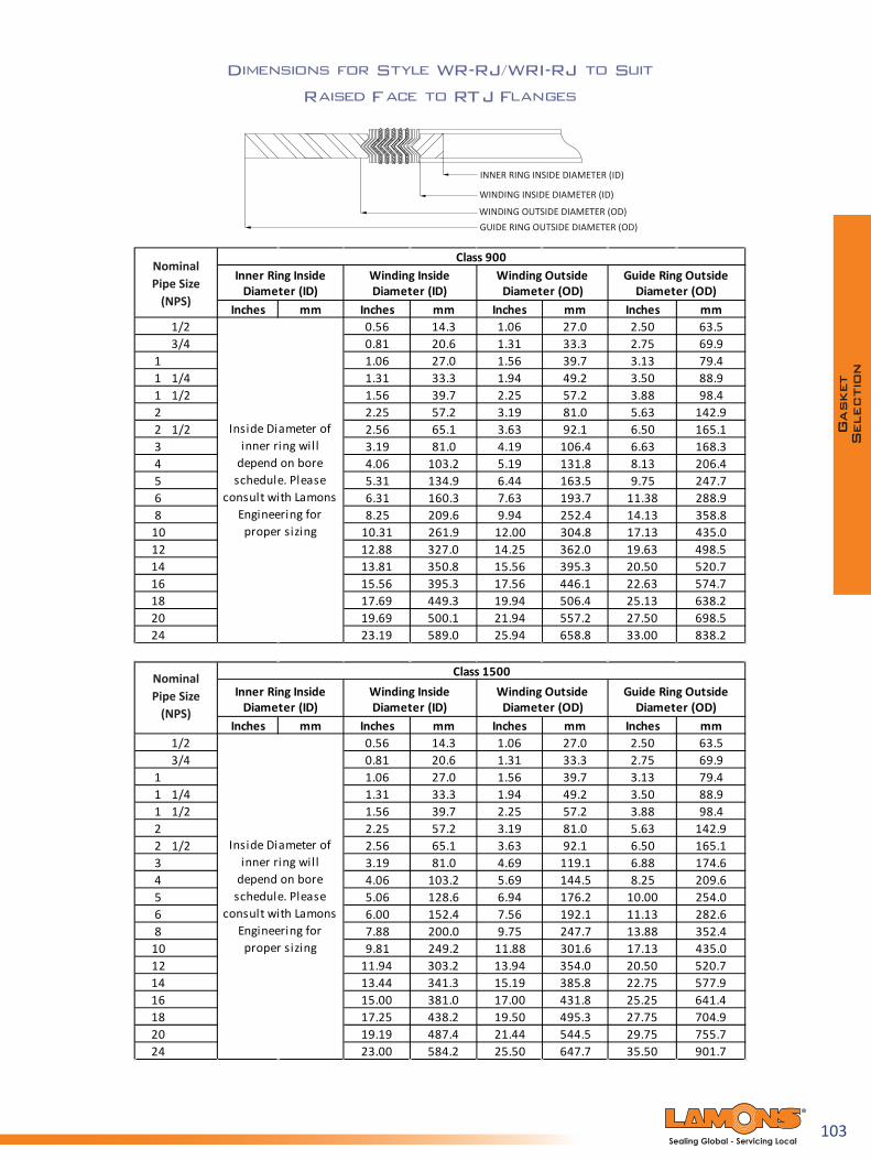
103Sealing Global - Servicing Local
Dimensions for Style WR-RJ/WRI-RJ to Suit
Raised Face to RTJ Flanges
INNER RING INSIDE DIAMETER (ID)
WINDING INSIDE DIAMETER (ID)
WINDING OUTSIDE DIAMETER (OD)GUIDE RING OUTSIDE DIAMETER (OD)
Inches mm Inches mm Inches mm Inches mm1/2 0.56 14.3 1.06 27.0 2.50 63.53/4 0.81 20.6 1.31 33.3 2.75 69.9
1 1.06 27.0 1.56 39.7 3.13 79.41 1/4 1.31 33.3 1.94 49.2 3.50 88.91 1/2 1.56 39.7 2.25 57.2 3.88 98.42 2.25 57.2 3.19 81.0 5.63 142.92 1/2 2.56 65.1 3.63 92.1 6.50 165.13 3.19 81.0 4.19 106.4 6.63 168.34 4.06 103.2 5.19 131.8 8.13 206.45 5.31 134.9 6.44 163.5 9.75 247.76 6.31 160.3 7.63 193.7 11.38 288.98 8.25 209.6 9.94 252.4 14.13 358.8
10 10.31 261.9 12.00 304.8 17.13 435.012 12.88 327.0 14.25 362.0 19.63 498.514 13.81 350.8 15.56 395.3 20.50 520.716 15.56 395.3 17.56 446.1 22.63 574.718 17.69 449.3 19.94 506.4 25.13 638.220 19.69 500.1 21.94 557.2 27.50 698.524 23.19 589.0 25.94 658.8 33.00 838.2
Inside Diameter of inner ring will
depend on bore schedule. Please
consult with Lamons Engineering for
proper sizing
Inner Ring Inside Diameter (ID)
Winding Inside Diameter (ID)
Winding Outside Diameter (OD)
Guide Ring Outside Diameter (OD)
Class 900
Inches mm Inches mm Inches mm Inches mm1/2 0.56 14.3 1.06 27.0 2.50 63.53/4 0.81 20.6 1.31 33.3 2.75 69.9
1 1.06 27.0 1.56 39.7 3.13 79.41 1/4 1.31 33.3 1.94 49.2 3.50 88.91 1/2 1.56 39.7 2.25 57.2 3.88 98.42 2.25 57.2 3.19 81.0 5.63 142.92 1/2 2.56 65.1 3.63 92.1 6.50 165.13 3.19 81.0 4.69 119.1 6.88 174.64 4.06 103.2 5.69 144.5 8.25 209.65 5.06 128.6 6.94 176.2 10.00 254.06 6.00 152.4 7.56 192.1 11.13 282.68 7.88 200.0 9.75 247.7 13.88 352.4
10 9.81 249.2 11.88 301.6 17.13 435.012 11.94 303.2 13.94 354.0 20.50 520.714 13.44 341.3 15.19 385.8 22.75 577.916 15.00 381.0 17.00 431.8 25.25 641.418 17.25 438.2 19.50 495.3 27.75 704.920 19.19 487.4 21.44 544.5 29.75 755.724 23.00 584.2 25.50 647.7 35.50 901.7
Inside Diameter of inner ring will
depend on bore schedule. Please
consult with Lamons Engineering for
proper sizing
Inner Ring Inside Diameter (ID)
Winding Inside Diameter (ID)
Winding Outside Diameter (OD)
Guide Ring Outside Diameter (OD)
Class 1500
NominalPipe Size
(NPS)
NominalPipe Size
(NPS)

104Sealing Global - Servicing Local
Markings for Standard Spiral Wound Gaskets
Markings for Standard Kammpro® Gaskets
LAM
ONS W
RI 2 150 316L FG 316L IR 316L OR ASM
E B1
6.20
Pressure Class
Nominal Pipe Size
Gasket Style
Inner Ring
Outer Ring
Winding MetalFiller Material
ASME B16.20or applicablespecification
Manufacturer'sName

105Sealing Global - Servicing Local
Lamons Corrugated Metal Gaskets (CMG®) Product Family
Lamons CMG gaskets are considered the standard in respect to corrugated metal gasket technology. They are an excellent choice for 150 and 300 class ASME fl anges where available bolt loading is minimal. The substrate geometry promotes recovery and resilience through thermal cycles and extended service life. CMG’s can be direct replacements for spiral wound gaskets and can eliminate inward buckling issues while creating a seal at moderate fl ange stresses. Available in a wide range of substrate alloys and covering layer options, CMG gaskets can be utilized to solve many common fl ange problems. CMG substrate geometries are designed to achieve maximum recovery characteristics. A specifi c pitch, core thickness and wall angle are engineered to maximize the seal’s ability to overcome problems associated with joint relaxation, pressure and thermal cycles. CMG is an excellent choice for pressure classes 150 and 300 ASME B16.5 fl anges where available load is minimal.
CMG
Lamons Corrugated Metal Gasket (CMG) is a high perfor-mance gasket for standard fl ange or heat exchanger appli-cations. The CMG molds in place by fi lling in irregularities of the spaces, creating a superior seal. It maintains the seal even in harsh environments, including hydrocarbons and steam applications. The gasket is ideal where low bolt load is present or where high gasket stresses are available. The thin profi le is benefi cial in areas where fl ange separation is limited. The heavy 22 gauge core and 1/8” (3.175 mm) pitch frequency results in superior recovery and crush resistance in the most demanding applications.
CMG-EX
Lamons CMG-EX gasket is a premium variation of Lamons original CMG gasket. The CMG-EX was designed specifi cally for heat exchanger applications and provides superior performance in cyclic applications and where a high level of radial shear is present. Differential movement between fl anges can cause tremendous relaxation issues on traditional heat exchanger gaskets. This problem is addressed in the design of the CMG-EX gasket, as it maintains a highest degree of tightness through operation and the full cycle event.
CMGT
Lamons CMGT style gasket maintains the same distinctive performance of the CMG, but provides an additional level of chemical resistance by utilizing a PTFE inner ring. Premium fl exible graphite covering layers are used over a corrugated substrate with a PTFE facing covering the inner perimeter of the gasket. This confi guration allows the user to maintain a “fi re safe” design but have the benefi ts of additional chemical resistance with less potential of graphite contamination in their process.
through thermal cycles and extended service life.
in a wide range of substrate alloys and covering layer

106Sealing Global - Servicing Local
CMG-PTFE
Lamons CMG-PTFE gasket is also based upon the same design as the CMG, but utilizes full expanded PTFE covering layers. This design is commonly used in FRP or plastic piping where low available load is critical. Premium chemical resistance is realized by the pure PTFE facings, and a variety of metallurgical substrates can be used to match the piping system. The same proprietary substrate geometry is utilized to optimize recovery and resilience.
CMG-HTG
Lamons CMG-HTG offers rebound and a recovery characteristics where movement between the fl anges is a concern, and oxidation of the graphite facing is a potential at elevated temperatures. Lamons CMG-HTG (high temperature gasket) is confi gured such that the sealing benefi t of graphite is included, and is protected with oxidation-resistant barriers of mica material.
Dimensions for Corrugated Metal Gasket (CMG)
to Suit ASME B16.5 Flanges
INSIDE DIAMETER (ID)OUTSIDE DIAMETER (OD)
NominalPipe Size
(NPS)
Inches mm Inches mm1/2 0.84 21 1.88 483/4 1.06 27 2.25 57
1 1.31 33 2.62 671 1/4 1.66 42 3.00 761 1/2 1.91 49 3.38 862 2.38 60 4.12 1052 1/2 2.88 73 4.88 1243 3.50 89 5.38 1373 1/2 4.00 102 6.38 1624 4.50 114 6.88 1755 5.56 141 7.75 1976 6.62 168 8.75 2228 8.62 219 11.00 279
10 10.75 273 13.38 34012 12.75 324 16.13 41014 14.00 356 17.75 45116 16.00 406 20.25 51418 18.00 457 21.62 54920 20.00 508 23.88 60724 24.00 610 28.25 718
Class 150
Inside Diameter (ID)
Outside Diameter (OD)
NominalPipe Size
(NPS)
Inches mm Inches mm1/2 0.84 21 2.12 543/4 1.06 27 2.62 67
1 1.31 33 2.88 731 1/4 1.66 42 3.25 831 1/2 1.91 49 3.75 952 2.38 60 4.38 1112 1/2 2.88 73 5.12 1303 3.50 89 5.88 1493 1/2 4.00 102 6.50 1654 4.50 114 7.12 1815 5.56 141 8.50 2166 6.62 168 9.88 2518 8.62 219 12.12 308
10 10.75 273 14.25 36212 12.75 324 16.62 42214 14.00 356 19.12 48616 16.00 406 21.25 54018 18.00 457 23.50 59720 20.00 508 25.75 65424 24.00 610 30.50 775
Class 300
Inside Diameter (ID)
Outside Diameter (OD)

107Sealing Global - Servicing Local
Information required to fill an order:
• Gasket shape per the standard shape index
• Metal material• Filler/facing material• Thickness
Dimensions required to fill an order:
A: Outside Diameter (OD)B: Inside Diameter (ID)D: Pass partition widthE: Distance from centerline of gasket to
centerline of first pass partitionF: Distance from centerline of gasket to
centerline of second pass partitionG: Distance from centerline of gasket to
centerline of third pass partitionH: Distance from centerline of gasket to
centerline of fourth pass partitionBCD: Bolt Circle DiameterBHD: Bolt Hole Diameter
R: Radius Number of bolt holes (for full face gasket shape)
Lamons Heat Exchanger Specifications
D
CL
CL
F
E
ø
øB
øA
CL
CL
D
R
øAøB
øBCD
øBHD
D
CL
CL
G H
E
F
øAøB

108Sealing Global - Servicing Local
Lamons Heat Exchanger Gaskets Standard shape index
K-3 K-4K-2K-1J-5 J-6 J-7 J-8
J-3 J-4J-2J-1I-8 I-9 I-10 I-11
I-6 I-7I-5I-4H-12 I-1 I-2 I-3
H-10 H-11H-9H-8H-4 H-5 H-6 H-7
H-2 H-3H-1G-9G-5 G-6 G-7 G-8
G-3 G-4G-2G-1E-4 F-1 F-2 F-3
E-2 E-3E-1D-2R C-1 C-2 D-1

109Sealing Global - Servicing Local
Lamons Metal & Jacketed GasketProduct F amily
Lamons jacketed gaskets are normally supplied with a non-asbestos, high temperature filler. The standard filler is normally sufficient for applications up to 900°F (482°C). Other soft fillers are available for higher temperatures or special applications. Standard metals used to make jacketed gaskets, regardless of the type, are aluminum, copper, the various brasses, soft steel, nickel, Monel®, Inconel®, and stainless steel types 304, 316, 321, 347, 410. The choice of metal used for the jacketed part of gasket would depend upon the service conditions being encountered.
Style 300 Double Jacketed Gasket
Double jacketed gaskets are most commonly used in heat exchanger applications. They are available in virtually any material that is commercially found in 26 gauge sheet. They are also used in standard flanges where the service is not critical and at temperatures beyond which a soft gasket can be used. Since most double jacketed gaskets are custom made, there is virtually no limit to the size, shape or configuration in which these gaskets can be made. This particular type of gasket can be used in a myriad of applications. Since the size and shape are not a problem and since most materials can be obtained commercially, this particular gasket style is popular. It must be remembered that the primary seal against leakage, using a double jacketed gasket, is the metal inner lap where the gasket is thickest before being compressed and densest when compressed. This particular section flows, affecting the seal. As a consequence, the entire inner lap must be under compression. Frequently, the outer lap is not under compression and does not aid in the sealing of the gasket. On most heat exchanger applications the outer lap is also under compression, providing a secondary seal. The intermediate part of a double-jacketed gasket does very little to effect the sealing capability of the gasket. In some cases, nubbins are provided on heat exchanger designs to provide an intermediate seal. This nubbin is normally 1/64” (0.4 mm) high by 1/8” (3 mm) wide. Experience has indicated, however, that there is little advantage to this particular design. The primary seal is still dependent on the inner lap of the gasket doing the brute work and the secondary seal, when applicable, would be provided by the outer lap.
Style 310 Plain Flat Metal Gaskets
Flat metal gaskets are best suited for applications such as valve bonnets, ammonia fittings, heat exchangers, hydraulic presses, tongue-and-groove joints. They can be used when compressibility is not required to compensate for flange surface finish, warpage or misalignment, and where sufficient clamping force is available to seat the particular metal selected. They must be sealed by the flow of the gasket metal into the imperfections on the gasket seating surfaces of the flange. This typically requires heavy compressive forces. The hardness of gasket metal must be less than the hardness of the flanges to prevent damage to the gasket seating surface of the flange. Flat metal gaskets are relatively inexpensive to produce and can be made of virtually any material that is available in sheet form. Size limitation is normally restricted to the sheet size. Larger gaskets can be fabricated by welding.
Note: Monel® and Inconel® are registered trademarks of Special Metals Corporation.
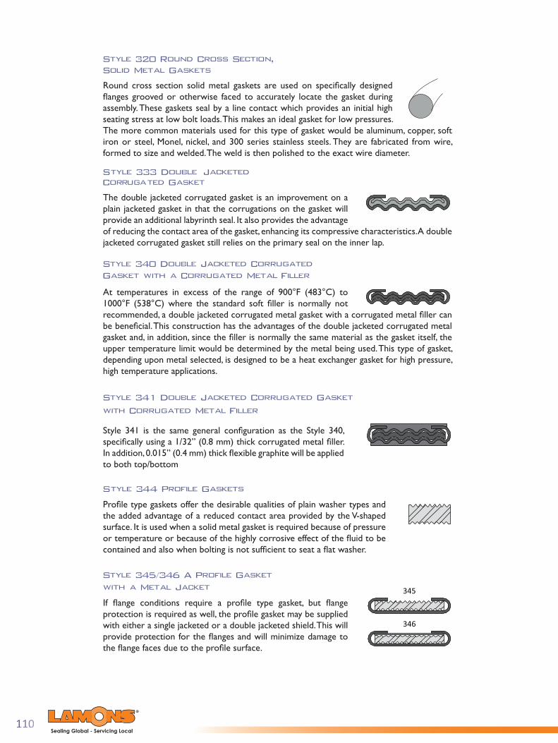
110Sealing Global - Servicing Local
Style 320 Round Cross Section, Solid Metal Gaskets
Round cross section solid metal gaskets are used on specifi cally designed fl anges grooved or otherwise faced to accurately locate the gasket during assembly. These gaskets seal by a line contact which provides an initial high seating stress at low bolt loads. This makes an ideal gasket for low pressures. The more common materials used for this type of gasket would be aluminum, copper, soft iron or steel, Monel, nickel, and 300 series stainless steels. They are fabricated from wire, formed to size and welded. The weld is then polished to the exact wire diameter.
Style 333 Double Jacketed Corrugated Gasket
The double jacketed corrugated gasket is an improvement on a plain jacketed gasket in that the corrugations on the gasket will provide an additional labyrinth seal. It also provides the advantage of reducing the contact area of the gasket, enhancing its compressive characteristics. A double jacketed corrugated gasket still relies on the primary seal on the inner lap.
Style 340 Double Jacketed Corrugated Gasket with a Corrugated Metal Filler
At temperatures in excess of the range of 900°F (483°C) to 1000°F (538°C) where the standard soft fi ller is normally not recommended, a double jacketed corrugated metal gasket with a corrugated metal fi ller can be benefi cial. This construction has the advantages of the double jacketed corrugated metal gasket and, in addition, since the fi ller is normally the same material as the gasket itself, the upper temperature limit would be determined by the metal being used. This type of gasket, depending upon metal selected, is designed to be a heat exchanger gasket for high pressure, high temperature applications.
Style 341 Double Jacketed Corrugated Gasket with Corrugated Metal Filler
Style 341 is the same general confi guration as the Style 340, specifi cally using a 1/32” (0.8 mm) thick corrugated metal fi ller. In addition, 0.015” (0.4 mm) thick fl exible graphite will be applied to both top/bottom
Style 344 Profile Gaskets
Profi le type gaskets offer the desirable qualities of plain washer types and the added advantage of a reduced contact area provided by the V-shaped surface. It is used when a solid metal gasket is required because of pressure or temperature or because of the highly corrosive effect of the fl uid to be contained and also when bolting is not suffi cient to seat a fl at washer.
Style 345/346 A Profile Gasket with a Metal Jacket
If fl ange conditions require a profi le type gasket, but fl ange protection is required as well, the profi le gasket may be supplied with either a single jacketed or a double jacketed shield. This will provide protection for the fl anges and will minimize damage to the fl ange faces due to the profi le surface.
346
345

111Sealing Global - Servicing Local
French Type Gaskets
French type gaskets are available in a one-piece jacketed construction for narrow radial widths not exceeding 1/4” (6.35 mm) and in two and three-piece constructions. This type of gasket can also be used with the jacket on the external edge of the gasket when the application requires the outer edge of the gasket to be exposed to fluid pressure. The most widely used French type gaskets are fabricated using a copper sheath. The double jacketed construction is preferred over the French or single jacketed construction, where practical, since it provides a totally sheathed gasket with none of the soft filler exposed.
Style 350 Single Jacketed Gasket
The majority of applications for single jacketed gaskets are normally 1/4” (6.35 mm) or less in radial width. This type of gasket is used in air tool applications and engine applications where space is limited, gasket seating surfaces are narrow and relatively low compressive forces are available for seating the gasket.
Style 382 Single Jacketed Overlap
In the single-jacketed overlap construction the maximum flange width is approximately 1/4” (6.4 mm). This type of gasket is used when total enclosure of the soft filler material is required and when the flange width makes it impractical to use a double jacketed gasket
Style 375 Double Jacketed Double Shell Gasket
The double-jacketed, double-shelled gasket is similar to the double jacketed gasket except that instead of using a shell and a liner, two shells are used in the fabrication of the gasket. It has the advantage of a double lap at both the ID and the OD of the gasket, adding greater stability to the gasket. The construction will withstand higher compressive loads. Double-shell gaskets are normally restricted to use in high pressure applications.
Style 395 Modified French Type
This particular type of gasket is normally used with very light flanges on duct work handling hot gases. Its construction consists of two French type shields welded together with a Cerafelt filler material on either side of the metal. Metal thickness is normally 26 gauge, rolled on the ID to act as a shield.
Style 370 Corrugated Gasket
The Style 370 includes adhering non-asbestos material strips or fiberglass cord to the corrugated faces – typically in the “valleys”.
Note: Without exception all of the solid metal gaskets require a very fine surface finish on the flanges. A flange with a flange surface roughness of 63 AARH or smoother is desired. Under no circumstances should the surface finish exceed 125 AARH. In addition, radial gouges or scores would be almost impossible to seal using solid metal gaskets.

112Sealing Global - Servicing Local
INSIDE DIAMETER (ID)
OUTSIDE DIAMETER (OD)
Dimensions for Double Jacketed (DJ) Gaskets per
ASME B16.20 to Suit ASME B16.5 Flanges
General Note: The gasket thickness tolerance is (+0.03 in., - 0.000 in.) (+0.8 mm, - 0.0 mm)
Note:(1) For gaskets NPS 1/2 through NPS 24, the outside and inside diameter tolerances are +0.06 in, - 0.0 in. (+1.5 mm, - 0.0 mm)
(2) There are no Class 400 fl anges for NPS 1/2 through NPS 3 (use Class 600)
(3) There are no Class 900 fl anges for NPS 1/2 through NPS 2 1/2 (use Class 1500)
(4) There are no Class 2500 fl anges NPS 14 and larger
Nominal Pipe Size (NPS)
Inches mm Inches mm Inches mm Inches mm1/2 0.880 22.4 -- -- 2.380 60.5 2.630 66.83/4 1.130 28.7 -- -- 2.630 66.8 2.880 73.2
1 1.500 38.1 -- -- 3.000 76.2 3.250 82.61 1/4 1.880 47.8 -- -- 3.380 85.9 4.000 101.61 1/2 2.130 54.1 -- -- 3.750 95.3 4.500 114.32 2.880 73.2 -- -- 5.500 139.7 5.630 143.02 1/2 3.380 85.9 -- -- 6.380 162.1 6.500 165.13 4.250 108.0 6.500 165.1 6.750 171.5 7.630 193.84 5.190 131.8 8.000 203.2 8.130 206.5 9.130 231.95 6.000 152.4 9.630 244.6 9.880 251.0 10.880 276.46 7.500 190.5 11.250 285.8 11.000 279.4 12.380 314.58 9.380 238.3 14.000 355.6 13.750 349.3 15.130 384.3
10 11.250 285.8 17.000 431.8 17.000 431.8 18.630 473.212 13.500 342.9 19.500 495.3 20.380 517.7 21.500 546.114 14.750 374.7 20.380 517.7 22.630 574.8 -- --16 16.750 425.5 22.500 571.5 25.130 638.3 -- --18 19.250 489.0 25.000 635.0 27.630 701.8 -- --20 21.000 533.4 27.380 695.5 29.630 752.6 -- --24 25.250 641.4 32.880 835.2 35.380 898.7 -- --
Gasket Inside Diameter (ID) (1) 900 (3)
Gasket Outside Diameter (OD) by Class (1)
1500 2500 (4)
Nominal Pipe Size (NPS)
Inches mm Inches mm Inches mm Inches mm Inches mm1/2 0.880 22.4 1.750 44.5 2.000 50.8 -- -- 2.000 50.83/4 1.130 28.7 2.130 54.1 2.500 63.5 -- -- 2.500 63.5
1 1.500 38.1 2.500 63.5 2.750 69.9 -- -- 2.750 69.91 1/4 1.880 47.8 2.880 73.2 3.130 79.5 -- -- 3.130 79.51 1/2 2.130 54.1 3.250 82.6 3.630 92.2 -- -- 3.630 92.22 2.880 73.2 4.000 101.6 4.250 108.0 -- -- 4.250 108.02 1/2 3.380 85.9 4.750 120.7 5.000 127.0 -- -- 5.000 127.03 4.250 108.0 5.250 133.4 5.750 146.1 -- -- 5.750 146.14 5.190 131.8 6.750 171.5 7.000 177.8 6.880 174.8 7.500 190.55 6.000 152.4 7.630 193.8 8.380 212.9 8.250 209.6 9.380 238.36 7.500 190.5 8.630 219.2 9.750 247.7 9.630 244.6 10.380 263.78 9.380 238.3 10.880 276.4 12.000 304.8 11.880 301.8 12.500 317.5
10 11.250 285.8 13.250 336.6 14.130 358.9 14.000 355.6 15.630 397.012 13.500 342.9 16.000 406.4 16.500 419.1 16.380 416.1 17.880 454.214 14.750 374.7 17.630 447.8 19.000 482.6 18.880 479.6 19.250 489.016 16.750 425.5 20.130 511.3 21.130 536.7 21.000 533.4 22.130 562.118 19.250 489.0 21.500 546.1 23.380 593.9 23.250 590.6 24.000 609.620 21.000 533.4 23.750 603.3 25.630 651.0 25.380 644.7 26.750 679.524 25.250 641.4 28.130 714.5 30.380 771.7 30.130 765.3 31.000 787.4
Gasket Inside Diameter (ID) (1)
Gasket Outside Diameter (OD) by Class (1)
150 300 400 (2) 600

113Sealing Global - Servicing Local
INSIDE DIAMETER (ID)
OUTSIDE DIAMETER (OD)
Dimensions for Double Jacketed (DJ) Gaskets per
ASME B16.20 to Suit ASME B16.47 Series A Flanges
General Note:The gasket thickness tolerance is +0.03 in, -0.000 in (+0.8 mm, -0.0 mm)
Notes:(1) For gaskets NPS 26 through NPS 60, the outside diameter and inside diameter tolerances are +0.13 in, -0.000 in (+3.3 mm, -0.0 mm).
(2) There are no Class 900 flanges for NPS 50 and larger.
Inches mm Inches mm Inches mm Inches mm26 26.50 673.1 30.38 771.7 32.75 831.9 32.63 828.828 28.50 723.9 32.63 828.8 35.25 895.4 35.00 889.030 30.50 774.7 34.63 879.6 37.38 949.5 37.13 943.132 32.50 825.5 36.88 936.8 39.50 1003.3 39.38 1000.334 34.50 876.3 38.88 987.6 41.50 1054.1 41.38 1051.136 36.50 927.1 41.13 1044.7 43.88 1114.6 43.88 1114.638 38.50 977.9 43.63 1108.2 41.38 1051.1 42.13 1070.140 40.50 1028.7 45.63 1159.0 43.75 1111.3 44.25 1124.042 42.50 1079.5 47.88 1216.2 45.75 1162.1 46.25 1174.844 44.50 1130.3 50.13 1273.3 47.88 1216.2 48.38 1228.946 46.50 1181.1 52.13 1324.1 50.00 1270.0 50.63 1286.048 48.50 1231.9 54.38 1381.3 52.00 1320.8 52.88 1343.250 50.50 1282.7 56.38 1432.1 54.13 1374.9 55.13 1400.352 52.50 1333.5 58.63 1489.2 56.13 1425.7 57.13 1451.154 54.50 1384.3 60.88 1546.4 58.63 1489.2 59.63 1514.656 56.50 1435.1 63.13 1603.5 60.63 1540.0 61.63 1565.458 58.50 1485.9 65.38 1660.7 62.63 1590.8 63.63 1616.260 60.50 1536.7 67.38 1711.5 64.63 1641.6 66.13 1679.7
Nominal Pipe Size
(NPS)
Outside Diameter (OD) by Class (1)
Inside Diameter(ID) (1)
Class 150 Class 300 Class 400 (2)
Inches mm Inches mm Inches mm26 26.50 673.1 34.00 863.6 34.63 879.628 28.50 723.9 35.88 911.4 37.13 943.130 30.50 774.7 38.13 968.5 39.63 1006.632 32.50 825.5 40.13 1019.3 42.13 1070.134 34.50 876.3 42.13 1070.1 44.63 1133.636 36.50 927.1 44.38 1127.3 47.13 1197.138 38.50 977.9 43.38 1101.9 47.13 1197.140 40.50 1028.7 45.38 1152.7 49.13 1247.942 42.50 1079.5 47.88 1216.2 51.13 1298.744 44.50 1130.3 49.88 1267.0 53.75 1365.346 46.50 1181.1 52.13 1324.1 56.38 1432.148 48.50 1231.9 54.63 1387.6 58.38 1482.950 50.50 1282.7 56.88 1444.8 -- --52 52.50 1333.5 58.88 1495.6 -- --54 54.50 1384.3 61.13 1552.7 -- --56 56.50 1435.1 63.13 1603.5 -- --58 58.50 1485.9 65.38 1660.7 -- --60 60.50 1536.7 68.13 1730.5 -- --
Nominal Pipe Size
(NPS)
Outside Diameter (OD) by Class (1)
Inside Diameter (ID) (1)
Class 600 Class 900 (2)
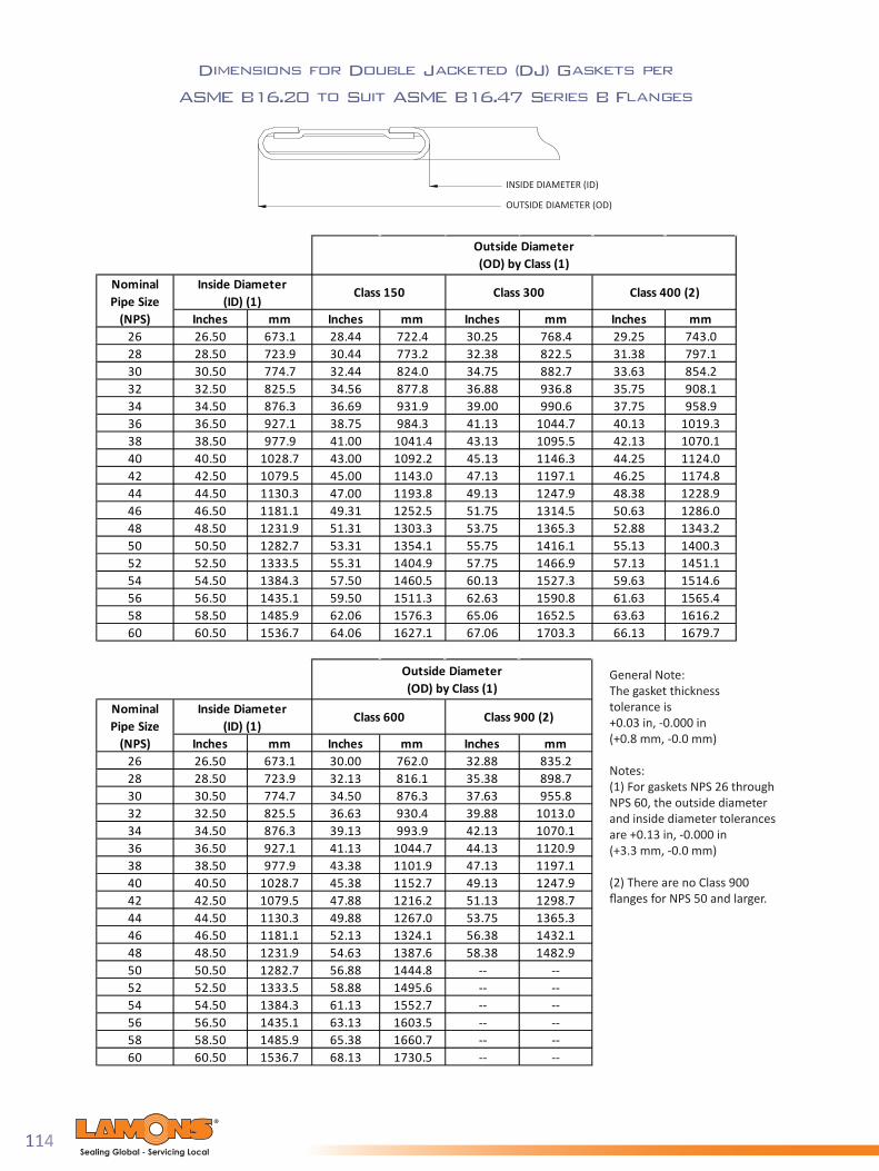
114Sealing Global - Servicing Local
INSIDE DIAMETER (ID)
OUTSIDE DIAMETER (OD)
Dimensions for Double Jacketed (DJ) Gaskets per
ASME B16.20 to Suit ASME B16.47 Series B Flanges
General Note:The gasket thickness tolerance is +0.03 in, -0.000 in (+0.8 mm, -0.0 mm)
Notes:(1) For gaskets NPS 26 through NPS 60, the outside diameter and inside diameter tolerances are +0.13 in, -0.000 in(+3.3 mm, -0.0 mm)
(2) There are no Class 900 fl anges for NPS 50 and larger.
Inches mm Inches mm Inches mm Inches mm26 26.50 673.1 28.44 722.4 30.25 768.4 29.25 743.028 28.50 723.9 30.44 773.2 32.38 822.5 31.38 797.130 30.50 774.7 32.44 824.0 34.75 882.7 33.63 854.232 32.50 825.5 34.56 877.8 36.88 936.8 35.75 908.134 34.50 876.3 36.69 931.9 39.00 990.6 37.75 958.936 36.50 927.1 38.75 984.3 41.13 1044.7 40.13 1019.338 38.50 977.9 41.00 1041.4 43.13 1095.5 42.13 1070.140 40.50 1028.7 43.00 1092.2 45.13 1146.3 44.25 1124.042 42.50 1079.5 45.00 1143.0 47.13 1197.1 46.25 1174.844 44.50 1130.3 47.00 1193.8 49.13 1247.9 48.38 1228.946 46.50 1181.1 49.31 1252.5 51.75 1314.5 50.63 1286.048 48.50 1231.9 51.31 1303.3 53.75 1365.3 52.88 1343.250 50.50 1282.7 53.31 1354.1 55.75 1416.1 55.13 1400.352 52.50 1333.5 55.31 1404.9 57.75 1466.9 57.13 1451.154 54.50 1384.3 57.50 1460.5 60.13 1527.3 59.63 1514.656 56.50 1435.1 59.50 1511.3 62.63 1590.8 61.63 1565.458 58.50 1485.9 62.06 1576.3 65.06 1652.5 63.63 1616.260 60.50 1536.7 64.06 1627.1 67.06 1703.3 66.13 1679.7
Class 300 Class 400 (2)Nominal Pipe Size
(NPS)
Outside Diameter (OD) by Class (1)
Inside Diameter(ID) (1)
Class 150
Inches mm Inches mm Inches mm26 26.50 673.1 30.00 762.0 32.88 835.228 28.50 723.9 32.13 816.1 35.38 898.730 30.50 774.7 34.50 876.3 37.63 955.832 32.50 825.5 36.63 930.4 39.88 1013.034 34.50 876.3 39.13 993.9 42.13 1070.136 36.50 927.1 41.13 1044.7 44.13 1120.938 38.50 977.9 43.38 1101.9 47.13 1197.140 40.50 1028.7 45.38 1152.7 49.13 1247.942 42.50 1079.5 47.88 1216.2 51.13 1298.744 44.50 1130.3 49.88 1267.0 53.75 1365.346 46.50 1181.1 52.13 1324.1 56.38 1432.148 48.50 1231.9 54.63 1387.6 58.38 1482.950 50.50 1282.7 56.88 1444.8 -- --52 52.50 1333.5 58.88 1495.6 -- --54 54.50 1384.3 61.13 1552.7 -- --56 56.50 1435.1 63.13 1603.5 -- --58 58.50 1485.9 65.38 1660.7 -- --60 60.50 1536.7 68.13 1730.5 -- --
Nominal Pipe Size
(NPS)
Outside Diameter (OD) by Class (1)
Inside Diameter (ID) (1)
Class 600 Class 900 (2)

115Sealing Global - Servicing Local
Section Three: Metallic Gaskets
Lamons Ring Type Joint (RT J) Gasket Product Family
Lamons manufactures and supplies a large variety of ring type joint gaskets. Lamons Ring Type Joint (RTJ) standard size gaskets are manufactured in accordance to API 6A, API 17D and ASME B16.20 specifi cations.
Ring joint gaskets come in two basic types, an oval cross section (Style 377) and an octagonal cross section (Style 388). These basic shapes are used in pressures up to 10,000 psi (64 MPa). The dimensions are standardized and require specially grooved fl anges. The octagonal cross section has a higher sealing effi ciency than the oval and would be the preferred gasket. However, only the oval cross section can be used in the old type round bottom groove. The newer fl at bottom groove design will accept either the oval or the octagonal cross section. The sealing surfaces on the ring joint grooves must be smoothly fi nished to 63 micro inches and be free of objectionable ridges, tool or chatter marks. RTJ assemblies seal by an initial line contact or an edging action as the compressive forces are applied.
The hardness of the ring should always be less than the hardness of the fl anges to prevent fl ange deformation. Dimensions for standard ring joint gaskets and grooves are covered in ASME B16.20 and API 6A, API 17D and ASME B16.5/B16.20.
Lamons stocks a wide range of sizes and materials ready for immediate shipment, from R11 to R105. Our extensive inventory of raw materials allows for best in class delivery of special sizes and shapes. Please consult with Lamons Engineering for design of non-standard items.
Octagonal (STYLE 388)Oval (STYLE 377)

116Sealing Global - Servicing Local
Material Designati onMaximumHardness
Rockwell B
MaximumHardness
BrinellSoft Iron D 56 90
Low Carbon Steel S 68 1204-6 Chrome F-5* 72 130
304 Stainless Steel S304 83 160316 Stainless Steel S316 83 160321 Stainless Steel S321 83 160347 Stainless Steel S347 83 160410 Stainless Steel S410 86 170
Alloy 625 INC 625 89 180Alloy 825 INC 825 92 195
Other CRAs Hardness shall meet Lamons material specifi cati ons*F-5 identi fi cati on designates ASTM Specifi cati onA 182 chemical compositi on requirements only
Typical Ring Joint Gasket Materials

117Sealing Global - Servicing Local
Size Designations for Oval or Octagonal Rings
2000 3000 5000
1/2 -- R-11 R-12 R-12 R-13 -- -- --3/4 -- R-13 R-14 R-14 R-16 -- -- --
1 R-15 R-16 R-16 R-16 R-18 -- -- --1 1/4 R-17 R-18 R-18 R-18 R-21 -- -- --1 1/2 R-19 R-20 R-20 R-20 R-23 -- -- --2 R-22 R-23 R-24 R-24 R-26 -- -- --2 1/16 -- -- -- -- -- R-232 1/2 R-25 R-26 R-27 R-27 R-28 -- -- --2 9/16 -- -- -- -- -- R-263 R-29 R-31 R-31 R-35 R-32 -- -- --3 1/8 -- -- -- -- -- R-353 1/2 R-33 R-34 R-34 -- -- -- -- --4 R-36 R-37 R-37 R-39 R-38 -- -- --4 1/16 -- -- -- -- -- R-395 R-40 R-41 R-41 R-44 R-42 -- -- --5 1/8 -- -- -- -- -- R-446 R-43 R-45 R-45 R-46 R-47 -- -- --7 1/16 -- -- -- -- -- R-468 R-48 R-49 R-49 R-50 R-51 -- -- --9 -- -- -- -- -- R-50
10 R-52 R-53 R-53 R-54 R-55 -- -- --11 -- -- -- -- -- R-5412 R-56 R-57 R-57 R-58 R-60 -- -- --13 5/8 -- -- -- -- --14 R-59 R-61 R-62 R-63 -- -- -- --16 R-64 R-65 R-66 R-67 -- -- -- --16 3/4 -- -- -- -- --18 R-68 R-69 R-70 R-71 -- -- -- --20 R-72 R-73 R-74 R-75 -- -- -- --20 3/4 -- -- -- -- -- R7421 1/4 -- -- -- -- -- R-73 -- --22 R-80 R-81 -- -- -- -- -- --24 R-76 R-77 R-78 R-79 -- -- -- --26 -- R-93 R-100 -- -- -- -- --28 -- R-94 R-101 -- -- -- -- --30 -- R-95 R-102 -- -- -- -- --32 -- R-96 R-103 -- -- -- -- --34 -- R-97 R-104 -- -- -- -- --36 -- R-98 R-105 -- -- -- -- --
2500NominalPipe Size
(NPS)150 300-600 900 1500
R-37
R-31
R-24
R-27
API 6A (psi)Flange Pressure Class
R-65
R-57
R-53
R-49
R-45
R-41

118Sealing Global - Servicing Local
Dimensions for Type R Octagonal and Oval Ring Gaskets
to Suit ASME B16.20 and API 6A
Tolerances:P = average pitch diameter of ring, ± 0.007” (±0.18 mm)A = width of ring, ± 0.008” (± 0.20 mm) B, H = height of ring, (+ 0.05”, -0.02”) (+1.3 mm, -0.5 mm) Variati on in height throughout the enti re circumference of any given ring shall not exceed 0.02” within these tolerances C = width of fl at on octagonal ring ± 0.008” (±0.20 mm) B1 = radius in ring, ± 0.02” (± 0.5 mm)23 deg = angle, ± 1/2 deg (± 0 deg 30min)
Inches mm Inches mm Inches mm Inches mm Inches mm Inches mmR-11 1.344 34.14 0.250 6.35 0.440 11.2 0.380 9.7 0.170 4.32 0.060 1.5R-12 1.563 39.70 0.313 7.95 0.560 14.2 0.500 12.7 0.206 5.23 0.060 1.5R-13 1.688 42.88 0.313 7.95 0.560 14.2 0.500 12.7 0.206 5.23 0.060 1.5R-14 1.750 44.45 0.313 7.95 0.560 14.2 0.500 12.7 0.206 5.23 0.060 1.5R-15 1.875 47.63 0.313 7.95 0.560 14.2 0.500 12.7 0.206 5.23 0.060 1.5R-16 2.000 50.80 0.313 7.95 0.560 14.2 0.500 12.7 0.206 5.23 0.060 1.5R-17 2.250 57.15 0.313 7.95 0.560 14.2 0.500 12.7 0.206 5.23 0.060 1.5R-18 2.375 60.33 0.313 7.95 0.560 14.2 0.500 12.7 0.206 5.23 0.060 1.5R-19 2.563 65.10 0.313 7.95 0.560 14.2 0.500 12.7 0.206 5.23 0.060 1.5R-20 2.688 68.28 0.313 7.95 0.560 14.2 0.500 12.7 0.206 5.23 0.060 1.5R-21 2.844 72.24 0.438 11.13 0.690 17.5 0.630 16.0 0.305 7.75 0.060 1.5R-22 3.250 82.55 0.313 7.95 0.560 14.2 0.500 12.7 0.206 5.23 0.060 1.5R-23 3.250 82.55 0.438 11.13 0.690 17.5 0.630 16.0 0.305 7.75 0.060 1.5R-24 3.750 95.25 0.438 11.13 0.690 17.5 0.630 16.0 0.305 7.75 0.060 1.5R-25 4.000 101.60 0.313 7.95 0.560 14.2 0.500 12.7 0.206 5.23 0.060 1.5R-26 4.000 101.60 0.438 11.13 0.690 17.5 0.630 16.0 0.305 7.75 0.060 1.5R-27 4.250 107.95 0.438 11.13 0.690 17.5 0.630 16.0 0.305 7.75 0.060 1.5R-28 4.375 111.13 0.500 12.70 0.750 19.1 0.690 17.5 0.341 8.66 0.060 1.5R-29 4.500 114.30 0.313 7.95 0.560 14.2 0.500 12.7 0.206 5.23 0.060 1.5R-30 4.625 117.48 0.438 11.13 0.690 17.5 0.630 16.0 0.305 7.75 0.060 1.5R-31 4.875 123.83 0.438 11.13 0.690 17.5 0.630 16.0 0.305 7.75 0.060 1.5R-32 5.000 127.00 0.500 12.70 0.750 19.1 0.690 17.5 0.341 8.66 0.060 1.5R-33 5.188 131.78 0.313 7.95 0.560 14.2 0.500 12.7 0.206 5.23 0.060 1.5R-34 5.188 131.78 0.438 11.13 0.690 17.5 0.630 16.0 0.305 7.75 0.060 1.5R-35 5.375 136.53 0.438 11.13 0.690 17.5 0.630 16.0 0.305 7.75 0.060 1.5R-36 5.875 149.23 0.313 7.95 0.560 14.2 0.500 12.7 0.206 5.23 0.060 1.5R-37 5.875 149.23 0.438 11.13 0.690 17.5 0.630 16.0 0.305 7.75 0.060 1.5R-38 6.188 157.18 0.625 15.88 0.880 22.4 0.810 20.6 0.413 10.49 0.060 1.5R-39 6.375 161.93 0.438 11.13 0.690 17.5 0.630 16.0 0.305 7.75 0.060 1.5R-40 6.750 171.45 0.313 7.95 0.560 14.2 0.500 12.7 0.206 5.23 0.060 1.5R-41 7.125 180.98 0.438 11.13 0.690 17.5 0.630 16.0 0.305 7.75 0.060 1.5R-42 7.500 190.50 0.750 19.05 1.000 25.4 0.940 23.9 0.485 12.32 0.060 1.5R-43 7.625 193.68 0.313 7.95 0.560 14.2 0.500 12.7 0.206 5.23 0.060 1.5R-44 7.625 193.68 0.438 11.13 0.690 17.5 0.630 16.0 0.305 7.75 0.060 1.5R-45 8.313 211.15 0.438 11.13 0.690 17.5 0.630 16.0 0.305 7.75 0.060 1.5R-46 8.313 211.15 0.500 12.70 0.750 19.1 0.690 17.5 0.341 8.66 0.060 1.5R-47 9.000 228.60 0.750 19.05 1.000 25.4 0.940 23.9 0.485 12.32 0.060 1.5R-48 9.750 247.65 0.313 7.95 0.560 14.2 0.500 12.7 0.206 5.23 0.060 1.5R-49 10.625 269.88 0.438 11.13 0.690 17.5 0.630 16.0 0.305 7.75 0.060 1.5R-50 10.625 269.88 0.625 15.88 0.880 22.4 0.810 20.6 0.413 10.49 0.060 1.5R-51 11.000 279.40 0.875 22.23 1.130 28.7 1.060 26.9 0.583 14.81 0.060 1.5R-52 12.000 304.80 0.313 7.95 0.560 14.2 0.500 12.7 0.206 5.23 0.060 1.5R-53 12.750 323.85 0.438 11.13 0.690 17.5 0.630 16.0 0.305 7.75 0.060 1.5R-54 12.750 323.85 0.625 15.88 0.880 22.4 0.810 20.6 0.413 10.49 0.060 1.5R-55 13.500 342.90 1.125 28.58 1.440 36.6 1.380 35.1 0.750 19.05 0.090 2.3R-56 15.000 381.00 0.313 7.95 0.560 14.2 0.500 12.7 0.206 5.23 0.060 1.5R-57 15.000 381.00 0.438 11.13 0.690 17.5 0.630 16.0 0.305 7.75 0.060 1.5
Width of Flat on Octagonal Ring (C)
Radius in Octagonal Ring (R1)
Height of Ring
Pitch Diameter of Ring (P)
Ring Number
Width of Ring (A) Oval (B) Octagonal (H)
Octagonal

119Sealing Global - Servicing Local
Inches mm Inches mm Inches mm Inches mm Inches mm Inches mmR-58 15.000 381.00 0.875 22.23 1.130 28.7 1.060 26.9 0.583 14.81 0.060 1.5R-59 15.625 396.88 0.313 7.95 0.560 14.2 0.500 12.7 0.206 5.23 0.060 1.5R-60 16.000 406.40 1.250 31.75 1.560 39.6 1.500 38.1 0.879 22.33 0.090 2.3R-61 16.500 419.10 0.438 11.13 0.690 17.5 0.630 16.0 0.305 7.75 0.060 1.5R-62 16.500 419.10 0.625 15.88 0.880 22.4 0.810 20.6 0.413 10.49 0.060 1.5R-63 16.500 419.10 1.000 25.40 1.310 33.3 1.250 31.8 0.681 17.30 0.090 2.3R-64 17.875 454.03 0.313 7.95 0.560 14.2 0.500 12.7 0.206 5.23 0.060 1.5R-65 18.500 469.90 0.438 11.13 0.690 17.5 0.630 16.0 0.305 7.75 0.060 1.5R-66 18.500 469.90 0.625 15.88 0.880 22.4 0.810 20.6 0.413 10.49 0.060 1.5R-67 18.500 469.90 1.125 28.58 1.440 36.6 1.380 35.1 0.780 19.81 0.090 2.3R-68 20.375 517.53 0.313 7.95 0.560 14.2 0.500 12.7 0.206 5.23 0.060 1.5R-69 21.000 533.40 0.438 11.13 0.690 17.5 0.630 16.0 0.305 7.75 0.060 1.5R-70 21.000 533.40 0.750 19.05 1.000 25.4 0.940 23.9 0.485 12.32 0.060 1.5R-71 21.000 533.40 1.125 28.58 1.440 36.6 1.380 35.1 0.780 19.81 0.090 2.3R-72 22.000 558.80 0.313 7.95 0.560 14.2 0.500 12.7 0.206 5.23 0.060 1.5R-73 23.000 584.20 0.500 12.70 0.750 19.1 0.690 17.5 0.341 8.66 0.060 1.5R-74 23.000 584.20 0.750 19.05 1.000 25.4 0.940 23.9 0.485 12.32 0.060 1.5R-75 23.000 584.20 1.250 31.75 1.560 39.6 1.500 38.1 0.879 22.33 0.090 2.3R-76 26.500 673.10 0.313 7.95 0.560 14.2 0.500 12.7 0.206 5.23 0.060 1.5R-77 27.250 692.15 0.625 15.88 0.880 22.4 0.810 20.6 0.413 10.49 0.060 1.5R-78 27.250 692.15 1.000 25.40 1.310 33.3 1.250 31.8 0.681 17.30 0.090 2.3R-79 27.250 692.15 1.375 34.93 1.750 44.5 1.630 41.4 0.977 24.82 0.090 2.3R-80 24.250 615.95 0.313 7.95 -- -- 0.500 12.7 0.206 5.23 0.060 1.5R-81 25.000 635.00 0.563 14.30 -- -- 0.750 19.1 0.377 9.58 0.060 1.5R-82 2.250 57.15 0.438 11.13 -- -- 0.630 16.0 0.305 7.75 0.060 1.5R-84 2.500 63.50 0.438 11.13 -- -- 0.630 16.0 0.305 7.75 0.060 1.5R-85 3.125 79.38 0.500 12.70 -- -- 0.690 17.5 0.341 8.66 0.060 1.5R-86 3.563 90.50 0.625 15.88 -- -- 0.810 20.6 0.413 10.49 0.060 1.5R-87 3.938 100.03 0.625 15.88 -- -- 0.810 20.6 0.413 10.49 0.060 1.5R-88 4.875 123.83 0.750 19.05 -- -- 0.940 23.9 0.485 12.32 0.060 1.5R-89 4.500 114.30 0.750 19.05 -- -- 0.940 23.9 0.485 12.32 0.060 1.5R-90 6.125 155.58 0.875 22.23 -- -- 1.060 26.9 0.583 14.81 0.060 1.5R-91 10.250 260.35 1.250 31.75 -- -- 1.500 38.1 0.879 22.33 0.090 2.3R-92 9.000 228.60 0.438 11.13 0.690 -- 0.630 16.0 0.305 7.75 0.060 1.5R-93 29.500 749.30 0.750 19.05 -- -- 0.940 23.9 0.485 12.32 0.060 1.5R-94 31.500 800.10 0.750 19.05 -- -- 0.940 23.9 0.485 12.32 0.060 1.5R-95 33.750 857.25 0.750 19.05 -- -- 0.940 23.9 0.485 12.32 0.060 1.5R-96 36.000 914.40 0.875 22.23 -- -- 1.060 26.9 0.583 14.81 0.060 1.5R-97 38.000 965.20 0.875 22.23 -- -- 1.060 26.9 0.583 14.81 0.060 1.5R-98 40.250 1022.35 0.875 22.23 -- -- 1.060 26.9 0.583 14.81 0.060 1.5R-99 9.250 234.95 0.438 11.13 -- -- 0.630 16.0 0.305 7.75 0.060 1.5
R-100 29.500 749.30 1.125 28.58 -- -- 1.380 35.1 0.780 19.81 0.090 2.3R-101 31.500 800.10 1.250 31.75 -- -- 1.500 38.1 0.879 22.33 0.090 2.3R-102 33.750 857.25 1.250 31.75 -- -- 1.500 38.1 0.879 22.33 0.090 2.3R-103 36.000 914.40 1.250 31.75 -- -- 1.500 38.1 0.879 22.33 0.090 2.3R-104 38.000 965.20 1.375 34.93 -- -- 1.630 41.4 0.977 24.82 0.090 2.3R-105 40.250 1022.35 1.375 34.93 -- -- 1.630 41.4 0.977 24.82 0.090 2.3
Width of Flat on Octagonal Ring (C)
Radius in Octagonal Ring (R1)
Height of Ring
Ring Number
Pitch Diameter of Ring (P)
Width of Ring (A) Oval (B) Octagonal (H)
Dimensions for Type R Octagonal and Oval Ring Gaskets
per ASME B16.20 and API 6A
Oval
Tolerances:P = average pitch diameter of ring, ±0.007” (±0.18 mm)A = width of ring, ±0.008” (±0.20 mm) B, H = height of ring, (+0.05”, -0.02”) (+1.3 mm, -0.5 mm) Variation in height throughout the entire circumference of any given ring shall not exceed 0.02” within these tolerances C = width of flat on octagonal ring ±0.008” (±0.20 mm) B1 = radius in ring, ±0.02” (±0.5 mm)23 deg= angle, ±1/2 deg (±0 deg 30min)

120Sealing Global - Servicing Local
RX Ring Designations for API 6B Flanges
RX ring gaskets are similar in shape to the standard octagonal ring joint gasket but their cross section is designed to take advantage of the contained fl uid pressure in effecting a seal. They are made to API 6A and interchangeable with standard octagonal rings for oil fi eld drilling and production applications in API 6B fl anges. RX is used at pressures up to 5,000 psi (34.37 MPa). Standard sizes are stocked in low carbon steel, 304 and 316.
RX Ring Designations for API 6B Flanges
*Crossover Flange Connecti ons
2000 psi 2900 psi 3000 psi 5000 psi lbs KgRX 20 1 1/2 -- 1 1/2 1 1/2 0.527 0.240RX 23 2 1/16 -- -- -- 1.150 0.523RX 24 -- -- 2 1/16 2 1/16 1.330 0.605RX 26 2 9/16 -- -- -- 1.420 0.645RX 27 -- -- 2 9/16 2 9/16 1.500 0.682RX 31 3 1/8 -- 3 1/8 -- 1.730 0.786RX 35 -- -- -- 3 1/8 1.910 0.868RX 37 4 1/16 -- 4 1/16 -- 2.090 0.950RX 39 -- -- -- 4 1/16 2.270 1.032RX 41 5 1/8 -- 5 1/8 -- 2.540 1.155RX 44 -- -- -- 5 1/8 2.720 1.236RX 45 7 1/16 -- 7 1/16 -- 2.960 1.345RX 46 -- -- -- 7 1/16 3.660 1.664RX 47 -- -- -- 8* 8.560 3.891RX 49 9 -- 9 -- 3.790 1.723RX 50 -- -- -- 9 5.360 2.436RX 53 11 -- 11 -- 4.560 2.073RX 54 -- -- -- 11 6.450 2.932RX 57 13 5/8 -- 13 5/8 -- 5.360 2.436RX 63 -- -- -- 14 26.400 12.000RX 65 16 3/4 -- -- -- 6.630 3.014RX 66 -- -- 16 3/4 -- 9.390 4.268RX 69 18 -- -- -- 7.520 3.418RX 70 -- -- 18 -- 20.140 9.155RX 73 21 1/4 -- -- -- 11.630 5.286RX 74 -- -- 20 3/4 -- 22.100 10.045RX 82 -- 1 -- -- 0.790 0.359RX 84 -- 1 1/2 -- -- 0.880 0.400RX 85 -- 2 -- -- 0.880 0.400RX 86 -- 2 1/2 -- -- 1.790 0.814RX 87 -- 3 -- -- 1.980 0.900RX 88 -- 4 -- -- 3.220 1.464RX 89 -- 3 1/2 -- -- 2.980 1.355RX 90 -- 5 -- -- 6.820 3.100RX 91 -- 10 -- -- 17.100 7.773RX 99 8* -- 8* -- 3.310 1.505
RX 201 -- -- -- -- 0.250 0.114RX 205 -- -- -- -- 0.300 0.136RX 210 -- -- -- -- 0.750 0.341RX 215 -- -- -- -- 1.500 0.682
API Ring Number
Sizes of Flange (Inches) Weight

121Sealing Global - Servicing Local
Dimensions for Type RX Ring Gaskets per
ASME B16.20 and API 6A
Note:(1) Rings RX-82 through RX-91 only require one pressure passage hole as illustrated. The Center line of the hole shall be located at the midpoint of dimension C.(2) Tolerance on these dimensions is (+0, -0.015”) (+0 mm,-0.38 mm).(3) Tolerance on these dimensions is (+0.02”, -0) (+0.5 mm, -0 mm)
Tolerances:OD = outside diameter of ring, +0.020”, -0 (+0.51 mm, -0 mm)A = width of ring, +0.008”, -0 (+0.20 mm, -0 mm) variation in width throughout the entire circumference of any ring shall not exceed 0.004” (0.10 mm) within these tolerances. C = width of flat, +0.006”, -0 (+0.15 mm, -0 mm)D = height of outside bevel, +0, -0.03” (+0 mm, -0.76 mm)H = height of ring, +0.008”, -0 (+0.20 mm, -0 mm) variation in height througout the entire circumference of any ring shall not exceed 0.004” (0.10 mm) within these tolerances.R1 = radius of ring, ±0.02” (±0.5 mm)E = hole size, ±0.02” (±0.5 mm)23 deg = angle, ±1/2 deg (±0 deg 30 min)
Inches mm Inches mm Inches mm Inches mm Inches mm Inches mm Inches mm
RX-20 3.000 76.20 0.344 8.74 0.182 4.62 0.125 3.18 0.750 19.05 0.060 1.5 -- --RX-23 3.672 93.27 0.469 11.91 0.254 6.45 0.167 4.24 1.000 25.40 0.060 1.5 -- --RX-24 4.172 105.97 0.469 11.91 0.254 6.45 0.167 4.24 1.000 25.40 0.060 1.5 -- --RX-25 4.313 109.55 0.344 8.74 0.182 4.62 0.125 3.18 0.750 19.05 0.060 1.5 -- --RX-26 4.406 111.91 0.469 11.91 0.254 6.45 0.167 4.24 1.000 25.40 0.060 1.5 -- --RX-27 4.656 118.26 0.469 11.91 0.254 6.45 0.167 4.24 1.000 25.40 0.060 1.5 -- --RX-31 5.297 134.54 0.469 11.91 0.254 6.45 0.167 4.24 1.000 25.40 0.060 1.5 -- --RX-35 5.797 147.24 0.469 11.91 0.254 6.45 0.167 4.24 1.000 25.40 0.060 1.5 -- --RX-37 6.297 159.94 0.469 11.91 0.254 6.45 0.167 4.24 1.000 25.40 0.060 1.5 -- --RX-39 6.797 172.64 0.469 11.91 0.254 6.45 0.167 4.24 1.000 25.40 0.060 1.5 -- --RX-41 7.547 191.69 0.469 11.91 0.254 6.45 0.167 4.24 1.000 25.40 0.060 1.5 -- --RX-44 8.047 204.39 0.469 11.91 0.254 6.45 0.167 4.24 1.000 25.40 0.060 1.5 -- --RX-45 8.734 221.84 0.469 11.91 0.254 6.45 0.167 4.24 1.000 25.40 0.060 1.5 -- --RX-46 8.750 222.25 0.531 13.49 0.263 6.68 0.188 4.78 1.125 28.58 0.060 1.5 -- --RX-47 9.656 245.26 0.781 19.84 0.407 10.34 0.271 6.88 1.625 41.28 0.090 2.3 -- --RX-49 11.047 280.59 0.469 11.91 0.254 6.45 0.167 4.24 1.000 25.40 0.060 1.5 -- --RX-50 11.156 283.36 0.656 16.66 0.335 8.51 0.208 5.28 1.250 31.75 0.060 1.5 -- --RX-53 13.172 334.57 0.469 11.91 0.254 6.45 0.167 4.24 1.000 25.40 0.060 1.5 -- --RX-54 13.281 337.34 0.656 16.66 0.335 8.51 0.208 5.28 1.250 31.75 0.060 1.5 -- --RX-57 15.422 391.72 0.469 11.91 0.254 6.45 0.167 4.24 1.000 25.40 0.060 1.5 -- --RX-63 17.391 441.73 1.063 27.00 0.582 14.78 0.333 8.46 2.000 50.80 0.090 2.3 -- --RX-65 18.922 480.62 0.469 11.91 0.254 6.45 0.167 4.24 1.000 25.40 0.060 1.5 -- --RX-66 18.031 457.99 0.656 16.66 0.335 8.51 0.208 5.28 1.250 31.75 0.060 1.5 -- --RX-69 21.422 544.12 0.469 11.91 0.254 6.45 0.167 4.24 1.000 25.40 0.060 1.5 -- --RX-70 21.656 550.06 0.781 19.84 0.407 10.34 0.271 6.88 1.625 41.28 0.090 2.3 -- --RX-73 23.469 596.11 0.531 13.49 0.263 6.68 0.208 5.28 1.250 31.75 0.060 1.5 -- --RX-74 23.656 600.86 0.781 19.84 0.407 10.34 0.271 6.88 1.625 41.28 0.090 2.3 -- --RX-82 2.672 67.87 0.469 11.91 0.254 6.45 0.167 4.24 1.000 25.40 0.060 1.5 0.060 1.5RX-84 2.922 74.22 0.469 11.91 0.254 6.45 0.167 4.24 1.000 25.40 0.060 1.5 0.060 1.5RX-85 3.547 90.09 0.531 13.49 0.263 6.68 0.167 4.24 1.000 25.40 0.060 1.5 0.060 1.5RX-86 4.078 103.58 0.594 15.09 0.335 8.51 0.188 4.78 1.125 28.58 0.060 1.5 0.090 2.3RX-87 4.453 113.11 0.594 15.09 0.335 8.51 0.188 4.78 1.125 28.58 0.060 1.5 0.090 2.3RX-88 5.484 139.29 0.688 17.48 0.407 10.34 0.208 5.28 1.250 31.75 0.060 1.5 0.120 3.0RX-89 5.109 129.77 0.719 18.26 0.407 10.34 0.208 5.28 1.250 31.75 0.060 1.5 0.120 3.0RX-90 6.875 174.63 0.781 19.84 0.479 12.17 0.292 7.42 1.750 44.45 0.090 2.3 0.120 3.0RX-91 11.297 286.94 1.188 30.18 0.780 19.81 0.297 7.54 1.781 45.24 0.090 2.3 0.120 3.0RX-99 9.672 245.67 0.469 11.91 0.254 6.45 0.167 4.24 1.000 25.40 0.060 1.5 -- --
RX-201 2.026 51.46 0.226 5.74 0.126 3.20 0.057 1.45 0.445 11.30 0.02 (3) 0.5 (3) -- --RX-205 2.453 62.31 0.219 5.56 0.12 3.05 0.072 (2) 1.83 (2) 0.437 11.10 0.02 (3) 0.5 (3) -- --RX-210 3.844 97.64 0.375 9.53 0.231 5.87 0.125 (2) 3.18 (2) 0.750 19.05 0.03 (3) 0.8 (3) -- --RX-215 5.547 140.89 0.469 11.91 0.21 5.33 0.167 (2) 4.24 (2) 1.000 25.40 0.06 (3) 1.5 (3) -- --
Ring Number
Pitch Diameter of Ring (P)
Width of Ring (A) Hole Size (E)(1)Width of Flat (C) Height of Outside Bevel (D)
Height of Ring (H) Radius of Ring (R1)
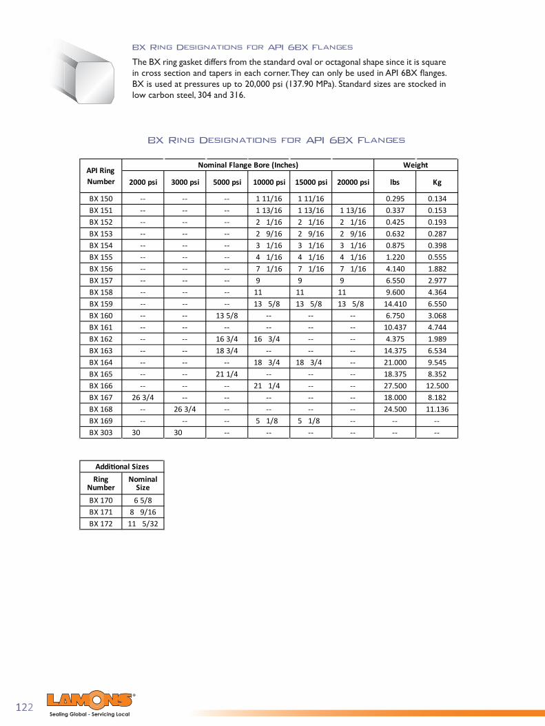
122Sealing Global - Servicing Local
BX Ring Designations for API 6BX Flanges
BX Ring Designations for API 6BX Flanges
The BX ring gasket differs from the standard oval or octagonal shape since it is square in cross section and tapers in each corner. They can only be used in API 6BX fl anges. BX is used at pressures up to 20,000 psi (137.90 MPa). Standard sizes are stocked in low carbon steel, 304 and 316.
2000 psi 3000 psi 5000 psi 10000 psi 15000 psi 20000 psi lbs Kg
BX 150 -- -- -- 1 11/16 1 11/16 0.295 0.134BX 151 -- -- -- 1 13/16 1 13/16 1 13/16 0.337 0.153BX 152 -- -- -- 2 1/16 2 1/16 2 1/16 0.425 0.193BX 153 -- -- -- 2 9/16 2 9/16 2 9/16 0.632 0.287BX 154 -- -- -- 3 1/16 3 1/16 3 1/16 0.875 0.398BX 155 -- -- -- 4 1/16 4 1/16 4 1/16 1.220 0.555BX 156 -- -- -- 7 1/16 7 1/16 7 1/16 4.140 1.882BX 157 -- -- -- 9 9 9 6.550 2.977BX 158 -- -- -- 11 11 11 9.600 4.364BX 159 -- -- -- 13 5/8 13 5/8 13 5/8 14.410 6.550BX 160 -- -- 13 5/8 -- -- -- 6.750 3.068BX 161 -- -- -- -- -- -- 10.437 4.744BX 162 -- -- 16 3/4 16 3/4 -- -- 4.375 1.989BX 163 -- -- 18 3/4 -- -- -- 14.375 6.534BX 164 -- -- -- 18 3/4 18 3/4 -- 21.000 9.545BX 165 -- -- 21 1/4 -- -- -- 18.375 8.352BX 166 -- -- -- 21 1/4 -- -- 27.500 12.500BX 167 26 3/4 -- -- -- -- -- 18.000 8.182BX 168 -- 26 3/4 -- -- -- -- 24.500 11.136BX 169 -- -- -- 5 1/8 5 1/8 -- -- --BX 303 30 30 -- -- -- -- -- --
API Ring Number
Nominal Flange Bore (Inches) Weight
Ring Number
Nominal Size
BX 170 6 5/8BX 171 8 9/16BX 172 11 5/32
Additional Sizes

123Sealing Global - Servicing Local
General Notes:(a) Radius R shall be 8% to 12% of the gasket height HNote:(1) One pressure passage hole is required per gasket as illustrated. The center line of the hole shall be located at the midpoint of dimension C.Tolerances: OD = outside diameter of ring (+0, -0.005”) (+0.00, -0.15 mm)H = height of ring (+0.008”, -0) (+0.20 mm, -0.00) Variation in height throughout the entire circumference of any ring shall not exceed (0.004”) (0.10 mm) within these tolerances.A = width of ring (+0.008”, -0) (+0.20 mm, -0) Variation in width throughout the entire circumference of any ring shall not exceed (0.004”) (0.10 mm)within these tolerances.ODT = outside diameter of flat (±0.002”) (±0.05 mm)C = width of flat (+0.006”, -0) (+0.15 mm, -0.00)D = hole size (±0.02”) (±0.5 mm)R = radius of ring, see general note (b)23 deg = angle, ±1/4 deg (±0 deg 150 min)
Dimensions for Type BX Ring Gaskets
to Suit ASME B16.20 and API 6A
Inches mm Inches mm Inches mm Inches mm Inches mm Inches mm Inches mmBX-150 1 11/16 43 2.842 72.19 0.366 9.30 0.366 9.30 2.790 70.87 0.314 7.98 0.060 1.5BX-151 1 13/16 46 3.008 76.40 0.379 9.63 0.379 9.63 2.954 75.03 0.325 8.26 0.060 1.5BX-152 2 1/16 52 3.334 84.68 0.403 10.24 0.403 10.24 3.277 83.24 0.346 8.79 0.060 1.5BX-153 2 9/16 65 3.974 100.94 0.448 11.38 0.448 11.38 3.910 99.31 0.385 9.78 0.060 1.5BX-154 3 1/16 78 4.600 116.84 0.488 12.40 0.488 12.40 4.531 115.09 0.419 10.64 0.060 1.5BX-155 4 1/16 103 5.825 147.96 0.560 14.22 0.560 14.22 5.746 145.95 0.481 12.22 0.060 1.5BX-156 7 1/16 179 9.367 237.92 0.733 18.62 0.733 18.62 9.263 235.28 0.629 15.98 0.120 3.0BX-157 9 229 11.593 294.46 0.826 20.98 0.826 20.98 11.476 291.49 0.709 18.01 0.120 3.0BX-158 11 279 13.860 352.04 0.911 23.14 0.911 23.14 13.731 348.77 0.782 19.86 0.120 3.0BX-159 13 5/8 346 16.800 426.72 1.012 25.70 1.012 25.70 16.657 423.09 0.869 22.07 0.120 3.0BX-160 13 5/8 346 15.850 402.59 0.938 23.83 0.541 13.74 15.717 399.21 0.408 10.36 0.120 3.0BX-161 16 5/8 422 19.347 491.41 1.105 28.07 0.638 16.21 19.191 487.45 0.482 12.24 0.120 3.0BX-162 16 5/8 422 18.720 475.49 0.560 14.22 0.560 14.22 18.641 473.48 0.481 12.22 0.060 1.5BX-163 18 3/4 476 21.896 556.16 1.185 30.10 0.684 17.37 21.728 551.89 0.516 13.11 0.120 3.0BX-164 18 3/4 476 22.463 570.56 1.185 30.10 0.968 24.59 22.295 566.29 0.800 20.32 0.120 3.0BX-165 21 1/4 540 24.595 624.71 1.261 32.03 0.728 18.49 24.417 620.19 0.550 13.97 0.120 3.0BX-166 21 1/4 540 25.198 640.03 1.261 32.03 1.029 26.14 25.020 635.51 0.851 21.62 0.120 3.0BX-167 26 3/4 679 29.896 759.36 1.412 35.86 0.516 13.11 29.696 754.28 0.316 8.03 0.060 1.5BX-168 26 3/4 679 30.128 765.25 1.412 35.86 0.632 16.05 29.928 760.17 0.432 10.97 0.060 1.5BX-169 5 1/8 130 6.831 173.51 0.624 15.85 0.509 12.93 6.743 171.27 0.421 10.69 0.060 1.5BX-170 6 5/8 168 8.584 218.03 0.560 14.22 0.560 14.22 8.505 216.03 0.481 12.22 0.060 1.5BX-171 8 9/16 217 10.529 267.44 0.560 14.22 0.560 14.22 10.450 265.43 0.481 12.22 0.060 1.5BX-172 11 5/32 283 13.113 333.07 0.560 14.22 0.560 14.22 13.034 331.06 0.481 12.22 0.060 1.5BX-303 30 762 33.573 852.75 1.494 37.95 0.668 16.97 33.361 847.37 0.457 11.61 0.060 1.5
Outside Diameter of Flat ODT
Width of Flat, C Hole Size, D (1)Ring Number
Nominal SizeOuterside
Diameter of Ring (OD)
Height of Ring, H Width of Ring, A

124Sealing Global - Servicing Local
Markings for Standard Ring Type Joint Gaskets
SRX and SBX Ring Gaskets
Type SRX and SBX gaskets per API 17D for Subsea Wellhead and Tree Equipment are vented to prevent pressure lock when connecti ons are made up underwater. They have identi cal measurements to RX and BX ring gaskets with the same number designati on, and they will fi t the same corresponding connectors. The “S” indicates these gaskets have cross-drilled holes, as fl uid entrapment in the ring groove can interfere with proper make up underwater (subsea). With the vent hole, any water trapped between a ring groove bott om and the sealing area of the gasket can escape to the equipment I.D. bore. Material per spec is defi ned as a corrosion resistant alloy.
SBX ring gaskets can be manufactured in two options for drilling the pressure passage holes as shown below.
The purpose of these two pressure passage holes is to prevent pressure lock whenconnections are made up underwater.
Opti on A Opti on B
Material Code and ProductSpecification Level
Lamons APILicense Number
API Monogram
Gasket RingNumber
Date of Manufacture
Material Heat NumberManufacturer's
Name
LAMONS 6A0112.1 RX39 S-4 08-11 21230

125Sealing Global - Servicing Local
Style 377R (Rubber Coated Rings)
Style 377R is a rubber coated oval ring gasket (usually steel) used in pressure test-ing to minimize damage to flanges. The rubber contact points provide additional seals while protecting the flange surfaces.
Style 377T (Transition Rings)
Style 377T, combination rings combine two different sizes having the same pitch diameter permitting bolt up of differing size flanges.
Bridgeman (Style 393)
The Bridgeman gasket is a pressure activated gasket for use on pressure vessel heads and valve bonnets for pressures of 1500 psi (10 MPa) and above. The cross section of the gasket is such that internal pressure acting against the ring forces it against the containing surface making a self-energized seal. Bridgeman gaskets are frequently silver plated or lead plated to provide a softer surface and minimize the force required to flow the gasket metal into the flange surface.
Delta (Style 392)
A delta gasket is a pressure actuated gasket used primarily on pressure vessels and valve bonnets at very high pressures in excess of 5000 psi (34 MPa). As with the lens gasket, complete drawings and material specifications must be supplied. Internal pressure forces the gasket material to expand when the pressure forces tend to separate the flanges. Extremely smooth surface finishes of 63 micro inches or smoother are required when using this type of gasket.
Lens (Style 394)
A lens type gasket is a line contact seal for use in high pressure piping systems and in pressure vessel heads. The lens cross section is a spherical gasket surface and requires special machining on the flanges. These gaskets will seat with a small bolt load since the contact area is very small and gasket seating pressures are very high. Normally the gasket materials should be softer than the flange. In ordering lens gaskets, complete drawings and material specifications must be supplied.

126Sealing Global - Servicing Local
Dimensions for Lens Rings per DIN 2696
(Millimeters)
Nominal Pipe d
d1S for d
Max
d2 Middler d3 X
Size (DN) min. max. ContactDiameter
Nominal Pressure PN64-40010 10 14 21 7 17.1 25 18 5.715 14 18 28 805 22 32 27 625 20 29 43 11 34 50 39 640 34 43 62 14 48 70 55 850 46 55 78 16 60 88 68 965 62 70 102 20 76.6 112 85 1380 72 82 116 22 88.2 129 97 13
100 94 108 143 26 116 170 127 15125 116 135 180 29 149 218 157 22150 139 158 210 33 171 250 183 26
Nominal Pressure PN64-100*175 176 183 243 31 202.5 296 218 28200 198 206 276 35 225 329 243 27250 246 257 332 37 277.7 406 298 25300 295 305 385 40 323.5 473 345 26350 330 348 425 41 368 538 394 23400 385 395 475 42 417.2 610 445 24
Nominal Pressure PN160-400*175 162 177 243 37 202.5 296 218 21200 183 200 276 40 225 329 243 25250 230 246 332 46 277.7 406 298 25300 278 285 385 50 323.5 473 345 30
r
d1
X S
d3
d2d
*Avoid using these Nominal Pipe Sizes

127Sealing Global - Servicing Local
Kammpro® Ring Type Joint (RT J ) Gaskets
Kammpro-ORJ
The Kammpro-ORJ is constructed to the standard octagonal API 6A or ASME B16.20 dimensions with the addition of the Kammpro design applied to the sealing areas and faced with oxidation resistant flexible graphite. This design is ideal for applications where cracking or embrittlement has been experienced in the ring joint groove. It is available in a large variety of metal material and can be fabricated as custom engineered designs. Special or custom sizing options are also available.
Kamm-PEG
Kamm-PEG represents a Pressure Energized Gasket with Kammprofiled sealing surfaces, where a RX type ring is typically used for high pressure reactors. Frequently, custom ring are used in the top and bottom of hydro processing reactors. To greatly enhance sealing ability, top and bottom OD angled sealing gasket surfaces are serrated per Kammprofiled specifications and faced with oxidation inhibited flexible graphite. It has the benefits of under compression graphite flows into minor imperfections creating higher seal tightness.
Kammpro Adapter (RT J TO RF)Kammpro-Adapter gaskets allow for ring type joint flanges to be mated up to raised face flanges, utilizing the strengths of the full metallic with the added benefit of kammprofiled sealing surfaces laminated with flexible graphite. Provided the pitch of the groove is sufficiently located under the raised face, this design is among the most robust of adapter styles.
Specialty Machined Products
Lamons maintains a high capacity of programable mill and lathe capability for custom machine work on most any specialty component. As a leading manufacturer of custom machined products for the refining, petrochemical and in-dustrial markets, Lamons recognizes the quality and service levels these industries require. We have over 30 state of the art CNC machines operated by programmers and machin-ists to deliver high quality machined components with the quickest response time in the industry.
From a sample, drawing or CAD file, Lamons can program and manufacture/machine custom parts with the highest precision and repeatability within 0.0005” (0.013 mm).
Specialty rings and industrial machined components can be rapidly produced to exact dimensions and to customer specification. Lamons stocks the most extensive inventory of centrifugal castings, forgings and plate in the industry allowing us to respond quickly to most any customer need. From small machined components to rings over 6 feet (1800 mm), Lamons has the capacity and turning capability to deliver most any configuration of heavy cross sectioned components.

w w w . l a m o n s . c o m
Lamons Corporate Headquarters7300 Airport Blvd.
Houston, Texas 77061United States
Phone: +1 713 222 0284Toll Free: 1 800 231 6906