Embed Size (px)
Citation preview

1
Gas Processing – State of the Art - Design Guide Line
Mahin Rameshni, P.E. President & CEO, Rameshni &
Associates Technology & Engineering LLC
Gas Treating in gas industries, and in oil and chemical facilities is getting more complex due to emissions
requirements established by environmental regulatory agencies. In addition, increasing demand of using
new wells with complex components and new sources of sour gases is encouraging gas specialists to
look forward to the new technologies, new solvents, and new ways to find solutions. In response to this
trend, gas preconditioning upstream, or final step(s) for gas conditioning downstream of the gas-treating
unit, are emerging as the best options to comply with the most stringent regulations. The final steps of
gas conditioning are a combination of different processes to remove impurities such as elemental sulfur,
solids, heavy hydrocarbons, and mercaptans that current commercial solvents are not able to handle. In
cases where there is no sulfur recovery / tail gas unit installed downstream of the gas plant to destroy
the remaining impurities, meeting the product specification is very crucial. Solvents could be
contaminated with undesired elements, causing plugging, foaming, corrosion, or changing the required
product specification. Over the years, many papers have been presented due to the gas preparation
required prior to any gas treating system. There is no indication, however, of any unique process that is
able to handle all of the impurities.
In cases where sulfur recovery and tail gas units are installed downstream of the gas plant, gas
preconditioning may not be required and most of the impurities will be destroyed in the sulfur recovery
unit. However, with the increasing sulfur content in crude oil and natural gas and the tightening
regulations of sulfur content in fuels, refiners and gas processors are being pushed to obtain additional
sulfur recovery capacity. At the same time, environmental regulatory agencies in many countries
continue to promulgate more stringent standards for sulfur emissions from oil, gas, and chemical
processing facilities. It is necessary to develop and implement reliable and cost effective technologies to
cope with the changing requirements. In response to this trend, several new Claus tail gas technologies
are emerging to comply with the most stringent regulations.
Typical sulfur recovery efficiencies for Claus plants are 90-96% for a two- stage plant, and 95-98% for a
three- stage plant. Most countries require sulfur recovery efficiency in the range of 98.5% to 99.9% or
higher. Therefore, the sulfur constituents in the Claus tail gas need to be reduced further.
The key parameters affecting the selection of the gas-treating and tail-gas cleanup process are:
• Selection of gas preconditioning process upstream or final gas
conditioning downstream of the gas treating unit based on nature
of impurities

2
• Gas pressure and temperature
• Feed gas composition, including H2S content, CO2 and
hydrocarbons, and other contaminants
• Process configuration
• Selection of the dehydration process
• Product specification, such as H2S, CO2, H2O, hydrocarbons, and
mercaptans
• Optimization of the existing equipment
• equired recovery efficiency
• Concentration of sulfur species in the stack gas
• Ease of operation
• emote location
• Sulfur product quality
• Costs (capital and operating)
In response to the above trends, selection of the right tools is very crucial. Those tools could be a “right”
technology, a “right” solvent, a “right” simulator, and a proper economic design with low- energy
consumption to reduce operating and capital costs.
Generic and specialty solvents are being divided into three different categories to achieve sales gas
specifications: 1) chemical solvents 2) physical solvents 3) and physical-chemical (hybrid) solvents. In
other words, regular gas units could be identified as amine units for H2S removal, dehydration process,
turbo expander for deep chilling, and caustic treatment for removing sulfur compounds from liquid
product. Or they could be specified as solvents for H2S Selectivity, solvents for CO2 emoval, and
solvents for organic Sulfur emoval.
Final selection is ultimately based on process economics, reliability, versatility, and environmental
constrains. Clearly, the selection procedure is not a trivial matter and any tool that provides a reliable
mechanism for process design is highly desirable. Acid gas removal is the removal of H2S and CO2 from
gas streams by using absorption technology and chemical solvents.
This paper emphasizes on the selection criteria for gas preconditioning and the final steps of gas
conditioning processes for industry needs.

3
The various gas-treating process technologies with commercialized chemical, physical, and hybrid
solvents to meet the various environmental regulations are presented. This paper also demonstrates
how these processes are chosen based on the selection criteria mentioned above.
The various Claus tail gas-treating technologies developed and commercialized to meet the various
environmental regulations are presented. Depending on the process route selected, an overall sulfur
recovery efficiency of 98.5% to 99.9% or higher is achievable. The latter recovery corresponds to less
than 250 parts per million by volume (ppmv) of SO2 in the offgas going to the thermal oxidizer prior to
its’ venting to the atmosphere.
As the results of the new revolutions in challenging the various solvents and different process
configurations, gas processing in gas industries and refineries has become more complex. In response to
this trend and to comply with the product specifications, more equipment and more process upstream
or downstream of gas processing should be implemented.
The selection criteria for gas processing is not limited to the selection of gas treating configurations by
itself; it is expanded to the selection criteria of more side process / down streams configurations, to
complete the gas processing in order to meet the product specification and to satisfy environmental
regulatory agency requirements.
For instance, if the H2S concentration of gas to the sulfur recovery unit is low, the acid gas enrichment
unit is recommended. Acid gas from the gas-treating unit flows through the acid gas enrichment unit
where the H2S has substantially separated from the CO2 and N2. The stream that is enriched in H2S is fed
to the sulfur recovery unit while the desulfurized CO2 and N2 stream is sent to the thermal incinerator.
Figure 1 represents the basic gas treating and sulfur recovery facilities. Acid gas and liquid sweetening
will be followed by the other process that is shown in figure 1. Liquid sweetening will be discussed in the
following sections.
Figure 1- Basic Gas Treating & Sulfur Recovery Facilities

4
Acid gas removal is the removal of H2S and CO2 from gas streams by using absorption technology and
chemical solvents. Sour gas contains H2S, CO2, H2O, hydrocarbons, COS/CS2, solids, mercaptans, NH3,
BTEX, and all other unusual impurities that require additional steps for their removal.
There are many treating processes available. However, no single process is ideal for all applications. The
initial selection of a particular process may be based on feed parameters such as composition, pressure,
temperature, and the nature of the impurities, as well as product specifications. The second selection of
a particular process may be based on acid/sour gas percent in the feed, whether all CO2, all H2S, or
mixed and in what proportion, if CO2 is significant, whether selective process is preferred for the
SU/TGU feed, and reduction of amine unit regeneration duty. The final selection could be based on
content of C3+ in the feed gas and the size of the unit (small unit reduces advantage of special solvent
and may favor conventional amine).
Final selection is ultimately based on process economics, reliability, versatility, and environmental
constraints. Clearly, the selection procedure is not a trivial matter and any tool that provides a reliable
mechanism for process design is highly desirable.
The variety of the acid gas sources that have different gas compositions, pressure, temperature, and
nature of impurities and might require different means of gas processing to meet the product
specification, are presented in table I.
Table I- Acid Gas Sources
Natural Gas Processing LNG Facilities
Petroleum efining Synthesis Gas Treating
Chemicals and Petrochemicals Coal & Heavy Oil Gasification
LPG Systems Pipeline Dew Point Control
Landfill Gas Facilities Feed to Tail Gas Treating
Ammonia & Hydrogen Plants
Selection of the right tools is very crucial. Establishing and conducting all the elements together at the
same time, would generate such a beautiful art in gas treating.
Natural Gas Processing
Natural gas is one of the common sources of gas treating, with a wide range in CO2/H2S ratios and high
pressure treating. If natural gas is not an LNG application, it could be treated with selective H2S removal
if significant CO2 is present. If C3+ is present, the desirability of using physical or mixed solvents is
reduced. If organic sulfur is present, the desirability of using physical or mixed solvents is increased.
It is favored to use proprietary solvents if natural gas has significant CO2 and /or H2S for large units/ and
to use conventional solvents for small units particularly with modest acid /sour gas levels.
5
Petroleum Refining
Petroleum refining is another source of gas treating with low CO2 content, unless the refinery has
catalyst cracking unit, in which case the gas may contain COS, organic sulfur, cyanides, ammonia, and
organic acids. The acid gas from hydrotreating and hydrocracking essentially contains H2S and ammonia.
The gas treating pressures and H2S specifications vary for individual applications, and MEA/DEA/MDEA
or formulated amines are the typical solvents. The refinery typically has multiple absorbers and a
common regenerator as listed below:
• Fuel gas treating
• Hydrotreater product/fuel gas
• Hydrotreater recycle gas
• Hydrocracker product/fuel gas
• Hydrocracker recycle gas
• LPG liq-liq contactor
• Thermal/catalyst cracker gases
• Services independent or combined as practical
Synthesis Gas Treatment
Synthesis gas treatment is characterized by high CO2 and low (or no) H2S. If the amount of CO2 is limited,
it is preferred to use selective H2S treating via formulated/hindered amine, mixed solvent, or physical
solvent. If H2S is not present and there is modest or essentially complete CO2 removal, it is preferred to
use activated MDEA, hot potassium, mixed amine, and physical solvent.
Data Base Outline
In order to select the optimized process, gas-treating units are divided into several categories and each
one requires different solvents, simulator, or available technology. However, each project is required to
be evaluated with more than one technology in order to meet the project specification, circulation rate,
and duties, which is truly dependent on the gas composition (such as H2S, CO2 and NH3). In addition, the
selected process must be evaluated to make sure it is economic.
Table II represents the most common process being used in gas plant industries.

6
Table II- Data Base Outline
HP Gas Treating System, Bulk CO2 Removal from Natural Gas, and
Selective H2S Removal
Physical Solvent Process (SELEXOL, Murphreesorb, IFPEXOL)
Other Solvent Process (DEA, MDEA, DGA, aMDEA, Sulfinol M/D, Flexsorb, Gas/SPEC *SS, Membrane +
amine, UCASOL, Chevron-IPN, Benfield, K2CO3)
Tail Gas Treating (H2S Recycle & Selective Cat. Oxidation Process
Typical Solvent (MDEA, HS-101/103, Gas/Spec *SS, Sulfinol, Flexsorb)
BS /Amine Process Shell SCOT/ ACO BOC ecycle
esulf Dual-Solve BS / Wet Oxidation
MCC CBA Sulfreen
BS /Selectox BS/Hi-Activity/POClaus Super Claus
Incinerator Tail Gas
Wellman-Lord Clintox Elsorb
Claus Master Cansolv Bio-Claus
Clausorb
Acid Gas Enrichment
Typical Solvent (MDEA, Sulfinol M/D, FLEXSORB, UCARSOL, Gas/SPEC *SS)
Ammonia Plants
Physical Solvents, aMDEA, Hot Potassium, Dow 800 series, etc.
Cryogenic Systems
Chemical Solvents
Enhanced Oil Recovery (EOR)
Chemical & physical Solvents
EOR CO2 Recovery Plants
Similar to Bulk CO2 emoval
Ethylene Plants
Similar to Bulk CO2 emoval
Flash Regeneration CO2 Removal
Similar to Bulk CO2 emoval

7
Hydrogen Plants
Chemicals Solvents
LPG Treating
Chemical Solvents
Oil Refinery Systems
Chemical & Physical Solvents
Dehydration systems
EG, DEG, TEG, Solvents, Methanol, Molecular Sieve Process, etc.
Unusual impurities are on the increase by demand of exploring new sources of the sour gas.
Following are some the unusual impurities that may require additional removal steps in gas -treating.
Feed gas compositions should be evaluated for needs of gas preparation prior entering to any gas plant.
Contaminated gas will damage the solvent and cause plugging, pipeline cleaning of liquids and solids,
corrosion, foaming, and changing product specifications. This paper addresses different aw Gas
Preconditioning and Final Conditioning processes.
• Elemental Sulfur
• Heavy Hydrocarbons (CnHm) & BTEX, such as Benzene & C8+
• COS, CS2, SH, Mercaptans, Hg
• Solids, Carbon
Elemental Sulfur Removal
Several studies have being performed regarding the elemental sulfur removal in gas plant industries.
Elemental sulfur causes the “series” problem within the gas plant such as plugging of exchangers, crystal
forming and contaminating the solvent, and changing the product specifications.
GPSA Engineering Data Book and the Perry and Chilton Chemical Engineering Handbook, show that the
gravity-based scrubbers are not effective for particles smaller than approximately 1 micron, whereas
filtration is effective for particles as small as 0.01 micron.
Sulfur is one of the elements that have a tendency to bond extensively to itself and chains in a similar
fashion to carbon, and produces S8. Chains can break and react with other molecules such as H2S or
produce solid sulfur that is suspended in the water.
Sulfur has the potential to act as a fairly strong oxidizing agent and causes corrosion in stainless steel
equipment.

8
Inline Separator / Filtration System
All gas-sweetening units should have a well-designed inlet separator. Inline separator has been used as a
filtration system to remove the particles and to remove any entrained solids. The inline separator should
be designed not only on the basis of inlet fluid volumes but also on surge capacity to handle slugs of
liquid hydrocarbons, H2O, and well-treated chemicals. In cases where solids or liquids are known or
anticipated to be a problem, a high-efficiency separator such as a coalescing filter separator should be
used.
The second stage of filtration should be performed by using the carbon filter for removing particles
down to 5 microns. The activated carbon filter should always be located downstream because the
deposition of solids would plug the carbon filter and prevent its regeneration.
If the gas is contaminated with the large amount of the elemental sulfur, even more steps should be
taken before entering the gas into the inline separator. Otherwise, inline separator will plug.
The latest filtration system is the implementation of designing the special media for the elemental sulfur
removal. This filter can facilitate the separation of the sulfur in conjunction with simultaneous liquid
aerosol removal. The liquid quantity would be available for assisting the separator, i.e. whether or not
additional water injection ahead of the filter would be necessary. This could be done by simply adding a
water injection upstream of the inlet nozzle. Due to the hazardous (lethal) nature of the gas, it would be
advisable to have the ability to steam or nitrogen-purge a unit that would need to be serviced. Basically,
the installation of this filter provides the ability to simultaneously water-wash the gas while providing
for sub-micron elemental sulfur removal. The filter media allows small liquid droplets to coalesce by
impingement. As larger droplets grow, they become sufficiently heavy to drain through the glass fibers.
To prevent plugging of the glass fibers, a pleated paper of prefilter could be used.
Disposal Solvent Injection
DAD’s and DMDS are well known as the disposal solvents that could be injected to the well to absorb
the elemental sulfur. The rich fluid, which contains elemental sulfur, is disposed and the solvent will not
be regenerated.
Sulfur Scrubbing by Using Chemical Solvent
The elemental sulfur removal is achievable by using absorption oil as a sulfur solvent in sour gas wells to
control sulfur deposition. This solvent is based on a mixture of alkylnaphthalenes diluted in a mineral oil;
both can physically combine with the precipitated sulfur. The solvent will be regenerated and its
behavior in corrosion inhibitors is outlined. This solvent, with an oil-soluble inhibitor having proper
phase behavior, can effectively control corrosion in sour gas wells with high reservoir water production.
Application of a solvent in sour gas wells should satisfy the following important characteristics:
• No corrosion with the well fluid

9
• Sufficient sulfur solubility
• No irreversible reactions with precipitated sulfur
• Stability under conditions
• Low vapor pressure
• Corrosion prevention
• Ability to separate from water
• Suitable uniform quality
• Suitable viscosity
• Ability to be regenerated and recirculated
• Simple recovery of the absorbent sulfur
The liquid is injected at the wellheads and travels by gravity through the annulus. The solvent mixes with
the upcoming gas and formation water and is reproduced by the well fluid. The annulus cross-section
narrows around the couplings of the tubing connectors. At high injection rates, the annulus becomes
partially filled up, forming a liquid column and creating slugs that travel through the tubing.
The produced liquid phases are separated at the surface by 3 three-stage systems consisting of a free-
water knockout drum, a separator, and the scrubber of the glycol dehydrator. The formation-
water/solvent mixture is collected in tanks at each well site.
The temperature decrease shifts the sulfur solubility of the gas to lower values. Depending on the
particular super-saturation of the gas, sulfur precipitation could take place in the cooler. To prevent
plugging of the cooler tubes, a small volume of solvent is injected downstream of the free-water
knockout drum, the sulfur loading capacity is about 30 g/L.
Slug Catchers
If the elemental sulfur content in the feed gas is very high, slug catchers are highly recommended to
remove the elemental sulfur. Slug catchers should be designed with enough capacity to remove all the
particles.
Gravity-Based Scrubber
The elemental sulfur could be removed by using the gravity-based scrubber with a separation flash drum
or settling storage tank that should be sized with sufficient residence time.

10
Heavy Hydrocarbon Removal
During phasing-in of new wells, feed gas is enriched with heavy hydrocarbons and oil. Hydrocarbon
liquids are known to cause foaming in amine systems. It has been found that hydrocarbon liquid may
reside in the piping; however, the liquid flow regime must be evaluated.
Then, the first option is to drain these hydrocarbons from pipelines. This liquid could be drained from a
pipe by installing dip legs at different locations such as at the end of header, and between the final two
branches.
The purpose of carbon filtration removal of hydrocarbon molecules and chemical contaminants, which
promote amine foaming, is to remove hydrocarbons prior to the amine unit.
Selective solvents have a capability of removing trace sulfur compounds, but hydrocarbon losses with
the acid gas are high.
Hydrocarbons have a higher solubility in physical solvent than in water; therefore, a higher physical
solvent concentration should result in an increase in hydrocarbon content in the acid gas. There are
other options could be used for hydrocarbon removal, such as:
• Using physical solvent for gas treating if applicable.
• Draining the heavy hydrocarbons from pipelines prior to gas plant.
• Providing a Water Wash Scrubber (with a separation flash drum
with sufficient residence time, the dissolved hydrocarbon can
gravity-separate from the bulk solution) and using baffles & weirs.
• Providing a gas carbon filter upstream of multi-cyclone separator
and coalescing filter.
• Providing skimming facilities such as skimming pots for flash drums
with sufficient residence time.
• Using mole-sieve bed downstream of the gas treating (mole-sieves
could be designed with multi-beds for the dehydration, aromatic
removal, and Hg removal, etc. in one package).
• Adding one or two fractionation columns within gas treating for the
removal of the remaining hydrocarbons, and to recover the C2-C4
and blend it back to the treated gas to maintain the required
heating value.
• If the amine-based solvent is applicable, some hydrocarbon removal
could be achieved by minimizing the lean amine, running stripper
with lower pressure, and using low circulation rate.

11
• If the sulfur recovery unit is located downstream of the gas plant,
the heavy hydrocarbons and BTEX could be destroyed by designing
a suitable burner to achieve 2,200 °F minimum. If the acid gas
feeding to the sulfur recovery unit has the low percent of H2S (Lean
Gas), oxygen enrichment is recommended.
If the gas has retrograde properties close to its hydrocarbon dew points, it is of particular importance to
minimize pressure losses. Drums could be equipped with proper hydrocarbon condensate withdrawal,
such as skimming pots.
BTEX Emissions
An amine unit operates by contacting an amine solution with the sour gas or liquid feed counter-
currently in an absorber column. H2S and CO2 in the feed are absorbed by the amine in the solution,
and the sweetened gas exits the top of the column. ich amine exits the bottom of the column and is
sent through the regeneration system to remove the acid gases and dissolved hydrocarbons, including
BTEX. The lean solution is then circulated to the top of the absorber to continue the cycle. The
sweetened gas exiting the absorber is saturated by water from its contact with the amine. The
overheads, including BTEX from the amine regenerator column, are sent to a sulfur recovery unit.
The aromatic compounds including benzene, Toluene, Ethylbenzene, and Xylene (collectively known as
BTEX), are included as hazardous factors in air pollutants.
If the raw gas contains appreciable amounts of H2S, a sulfur plant is used to treat the overheads from
the rich amine stripper. This treating normally destroys any BTEX or other hydrocarbons. Several
operating parameters directly affect the amount of BTEX absorbed in an amine unit, such as inlet BTEX
composition, contactor operating pressure, amine circulation rate, solvent type, and lean solvent
temperature.
MDEA absorbs the lowest amount of BTEX compared to DEA and MEA; therefore, it is recommended to
use MDEA where BTEX is observed in the sour gas, (if it is applicable).
Several operating parameters directly affect the amount of BTEX absorbed in an amine unit. These
factors include the inlet BTEX composition, contactor operating pressure, amine circulation rate, solvent
type, and lean solvent temperature. Following is a list of strategies that should be followed to limit the
BTEX emissions from gas plant:
• Minimize the lean amine temperature. The amount of BTEX
emissions in amine systems decreases with an increase in lean
solvent temperature.
• Use the best solvent for treating requirements. (i.e. MDEA absorbs
the lowest amount of BTEX).

12
• Minimize the lean circulation rate. BTEX pick up increases almost
linearly with an increase in circulation rate.
• If the stripper pressure is higher, the overall BTEX emissions are
lower.
Sulfur has the potential to act as a fairly strong oxidizing agent and cause corrosion in stainless steel
equipment.
H2S is very soluble in molten sulfur; so then H2S would be expected from typical solubility’s of gases into
liquids. Sulfur reacts with hydrocarbons to form mercaptans, which are present in sour gas. The high
solubility of sulfur in CS2 has been recognized. Other solvents are oily disulfides, amines, alkanolamines,
and aromatic hydrocarbons. Amines and alkanolamines compounds are extensively used in German
sour-production schemes and depend on the following reaction for taking up sulfur.
NH2 + H2S � NH3 + HS9
Technology has been patented for loop systems using this approach.
Sulfur should be managed and it is reasonable to predict that a suitable chemical base might prevent
sulfur deposition. Acid-base reactions are rapid compared to decomposition reactions and could act to
capture the sulfanes as ionic polysulfides before decomposition occurs.
If water is contaminated with bicarbonate, that water becomes corrosive. This is a suggestion here that
indicates aqueous sodium bicarbonate should be injected into the bottom of the wellbore to control
sulfur deposition until production matures and the formation water takes over.
If the gas containing high levels of sulfur, say more than 10 tons per day is to be removed, then a
regenerable H2S adsorption / desorption process, such as a Claus process for the conversion of the
removed H2S into elemental sulfur, is normally favored.
If less than a few hundred pounds/day of sulfur needs to be removed, fixed beds of chemical absorbents
will remove H2S to any level required. The used catalysts and absorbents can be sold to the metal
recovery industry, and there are no disposal problems.
Integration with Membranes
Membranes are now being used widely for the purification of natural gas containing high levels of CO2.
For instance, it has developed a membrane-based process to separate and recover hydrocarbons,
including propylene and ethylene, from nitrogen and light gases. Unfortunately, the membranes
available presently lack selectivity, and it is not possible to precisely control the rate of diffusion of the
various components present across the membrane. Therefore, it is rare for the stripped gas to meet the
sales gas specification.

13
Integration with Molecular Sieves
Molecular sieves are used extensively to dry natural gas. In this role, they will also remove H2S but
because water is significantly more powerfully bonded than H2S, they are not very effective for the
combined H2S/H2O removal duty.
The new technology is using the molecular sieves as a multi-bed combination, each for a specific duty.
This combination could be a dehydration bed, in addition to a removal bed for heavy hydrocarbon(s),
Hg, or any other impurities that could be effectively selected for removal technology. These beds should
be cost effectively designed.
COS /CS2 Removal
Some of the chemical and physical solvents are capable of removing COS / CS2 at some level; however,
the solvent may not be able to meet the product specification. In that case, using another conditioning
process is feasible. The molecular sieves process could be used for COS / CS2. The amine reclaimer
system is an alternative for COS / CS2. eclaimer operation is a semi-continuos batch operation for
removal of degradation product from the solution and removal of suspended solids and impurities.
eclaimer operates on a side stream of 1-3 percent of total solvent circulation rate. If a physical solvent
is being used for the acid gas removal, COS / CS2 could be improved by increasing the fresh solvent
circulation rate since the semi-solvent is already saturated and providing an additional chiller system
would increase the absorption process.
Any gas treating, including natural gas and refinery offgas, are contaminated with mercaptan and COS.
Any gas-treating unit operates by contacting a solvent solution with the sour gas or liquid feed counter-
currently in an absorber column. H2S and CO2 in the feed are absorbed by the solvent in the solution,
and the sweetened gas exits the top of the column. ich solvent exits the bottom of the column and is
sent through the regeneration system to remove the acid gases, dissolved hydrocarbons, and COS.
Several operating parameters directly affect the amount of COS absorbed in a gas treating unit, such as
inlet COS composition, contactor operating pressure, solvent circulation rate, solvent type, and lean
solvent temperature. The chosen solvent should be capable of absorbing COS in the absorption process
and release the COS to the acid gas in the regenerator. The acid gas from the regenerator is sent to the
sulfur recovery unit to decompose any sulfur compounds, including COS.
Pure physical solvent is particularly effective in a high-pressure system, high-acid gas treatment for
removing H2S, CO2, COS, organic sulfur species, and a wide range of other gas stream contaminates.
Usually, two absorbers are designed with physical solvents, one absorber for H2S removal with semi-lean
physical solvent and another absorber for CO2 and COS removal with lean, pure solvents. If more
absorption of COS is required, additional free-COS, free-lean solvent should be fed to the H2S absorber,
or semi-lean physical solvent has to be cooled prior feeding the H2S absorber.

14
The purpose of the amine reclaiming units is to distill the water and amine from the fouled solution
leaving behind the entrained solids, dissolved salts, and degradation products that cause foaming and
corrosion problems.
The reclaimer is an integral part of a successful amine sweetening process. It normally operates on a
side stream of the lean amine solution leaving the bottom of the stripper column. The temperature of
the reclaimer is to be controlled through the cycle. The presence of COS, CS2, FeSO2, free oxygen, and
other contaminants can poison the amine. In such cases, a reclaimer is often used to regenerate the
degraded amine. Amine degradation depends on different factors. All of the feed to the reclaimer is
assumed to go overhead except the degraded amine. A flash calculation would be essentially impossible
since the composition and properties of the degraded amine vary widely and are never accurately
determined. The reclaimer has only one inlet stream that comes from the reboiler, and two outlet
streams (the reclaimer OVHD and the reclaimer dump). The reclaimer operating temperature is in a
range of 300-350 ° F and, usually, 1-5 percent of the lean amine would be fed to the reclaimer.
Effect of NH3
When small amounts of ammonia are present in the sour gas, nearly all of the ammonia should be
scrubbed from the sour gas by the amine solution. Due to the high solubility of ammonia in water, the
ammonia may build up in the circulating rich-amine solution and present several problems in the
absorber and stripper. Some of the operational problems with ammonia are meeting the project
specification, flood in the stripper, inability to hold the pressure control set points on the condenser or
reboiler.
These problems all have the same root cause. Ammonia is absorbed at the pressure and temperature in
the absorber, rich amine is loaded with ammonia fed to the stripper, and the K value for ammonia in the
condenser is considerably less than one. Therefore, most of the ammonia is vaporized in the stripper,
and is returned in the reflux. This process continues to build up until steady-state ammonia either
overcomes the low K value in the condenser or forces its way to the reboiler against high K value in the
tower.
Dehydration Process
Gas hydrates are crystalline compounds composed of water and natural gas in the pipelines. The
conditions that tend to promote hydrate formation include the following: low temperature, high
pressure, and a gas at, or below, its water dew point with free water present. The formation of hydrates
can be prevented by using any of the following methods:
• Adjusting the temperature and pressure until hydrate formation is
not favored.
• Dehydrating a gas stream to prevent a free water phase.
• Inhibiting hydrate formation in the free water phase.
15
EG, DEG, and TEG are the most widely used solvents for bulk removal of water from natural gas.
Methods of calculations are the K-chart method and Hammer Schmidt’s Equation, which are both
presented in GPSA, 1994, and computer simulation.
Use of amines in aqueous solutions saturates the sweet gas with water vapor, regardless of whether the
entering sour gas is wet or dry.
For some amine processes, this means that a dehydration step necessarily follows sweetening. One
process, which overcomes this shortcoming, is the use of MDEA or DEA in combination with ethylene or
diethylene-glycol.
The combination of amine and glycol will usually do an excellent job in removing acid gas constituents,
but generally does not dehydrate as well as a conventional glycol installation.
Using other technologies, capable of water removal, could be EG injection, methanol-protected cold
processes, hydrate- formation temperature predications, and Cold Finger Drizo. Finally, the molecular
sieve process is an alternative for the dehydration process in addition to removal of other impurities.
The most common amine design configuration includes one single absorber, one single regenerator, and
all related equipment such as pumps, filters, and heat exchangers. Sometimes other configurations
required to be considered to be able to design the gas treating units, in addition to being able to meet
the project requirement. Other considerations are listed below as a reference:
• One single absorber, and one single regenerator
• One single absorber, and several flash stages
• Absorber A in series with absorber B, and single regenerator
• Absorber A/B in parallel with a common regenerator
• Split –flow configuration using absorber A, B, or A/B
• Absorber A/B with two lean amine feeds
• Absorber A/ B and regenerator with side heaters / coolers
• Single –Stage Co-current static mixing element
• Absorber A/B with amine pump-around
• One single absorber, one single regenerator, with amine and Semi-amine split flow
• H2S & CO2 Absorbers, one single egenerator, with amine and Semi-amine split flow
• Molecular sieve process
• Membrane process
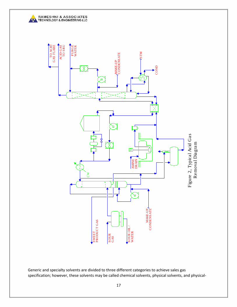
Figure 2 represents the typical amine unit configuration. Some of the above configurations are not
common processes; therefore, a brief description follows:
Absorber with pump-around may be used when a gas stream containing, for example nine mole percent
of CO2. In order to reduce the total circulation of the solvent, an internal recycle or pump-around circuit
is used with a heat exchanger to cool the stream. The process enables recovery of 89% of CO2 in the
feed gas.

16
Split- flow may be used to provide a significant reduction in the amount of stripping steam needed. Lean
and semi-lean solvent enters the absorber to sweeten the gas. The partially stripped semi-lean solvent
stream is drawn off the third tray of the regenerator.
Molecular sieve process may be used for selectivity of H2S removal in the presence of CO2.
In this process, the gas passes through one of two to four fixed beds of molecular sieves, where the H2S
along with H2O and organic sulfur compounds are removed from the gas by a process similar to
adsorption. When the bed becomes saturated with H2S, the main gas flow is switched to another bed,
which is freshly regenerated. Twenty percent of the sweet gas is heated to 600 -700 °F, and passed
through the fouled bed to regenerate it. The hot regeneration gas is then cooled and processed by an
amine unit to remove H2S from the regeneration gas. The regeneration gas is sweetened; it rejoins the
main gas stream downstream of the sieve beds.
Liquid Treating
Liquid treating is another amine unit for sweetening hydrocarbon liquids by using DEA, MDEA, or MEA
solvent.
The acid condensate-sweetening unit removes H2S and CO2 from the acid condensate feed by liquid-
liquid contacting the sour condensate with lean solvent such as DEA.
The sour condensate flows through the acid condensate coalesce filter where particulate matter is
removed and entrained water is coalesced and separated. The acid condensate then flows to the acid
condensate contactors where CO2 and H2S are absorbed by the lean DEA solution.
The contactors are liquid-liquid contactors containing 2 or 3 packed sections. The treated condensate
from the acid condensate contactor is washed using a recirculating water wash. The treated condensate
and the wash water are mixed in the water-wash static mixer. The mixer is then coalesced into two
liquid phases and separated in the water-wash separator.
Makeup water is continuously added to the circulating water-wash circuit to control the buildup of DEA
in the wash water and to help maintain the water content of the DEA system. Water is also
continuously withdrawn from the water-wash circuit and mixed with the rich DEA solution.
In this process, liquid hydrocarbon enters the bottom of a packed absorber and lean amine enters the
top of the absorber. Sweet liquid leaves the absorber from the top and rich amine leaves the absorber
from the bottom. The most common liquid–liquid absorbers are packed contactors, jet educator-mixers,
and static mixers. However, other processes such as Merox, Molecular Sieve, KOH, and Iron Sponge
could do the liquid treating process.
17
Generic and specialty solvents are divided to three different categories to achieve sales gas
specification; however, these solvents may be called chemical solvents, physical solvents, and physical-
TO
AC
IDG
AS
FL
AR
E
AC
ID G
AS
TO
SR
U
PU
RG
EW
AT
ER
SW
EE
TP
RO
DU
CT
GA
S
SO
UR
GA
S
SO
UR
OIL
/W
AT
ER
CW
MA
MIN
ED
RA
IN
ST
M
MA
KE
-UP
CO
ND
EN
SA
TE
MA
KE
-UP
CO
ND
EN
SA
TE
CO
ND
Fig
ure
2,
Typic
al A
cid
Gas
Rem
oval D
iagra
m
18
chemical (hybrid) solvents. On the other hand, regular amine units are divided into an amine unit for H2S
removal, molecular sieve dehydration, turbo expander for deep chilling, and caustic treating for
removing sulfur compounds from liquid product, or finally, are divided to:
• Solvents for H2S selectivity
• Solvents for CO2 removal
• Solvents for organic sulfur removal
The primary differences in process by using generic amines are in solution concentrations. MEA is
ordinarily used in a 10 to 20 percent by weight in the aqueous solution. DEA is also used in the 10 to 30
percent by weight in the aqueous solution. DIPA, DGA, and MDEA are used in higher concentrations.
Typical concentration ranges for DIPA and MDEA are 30 to 50 percent by weight in the aqueous solution.
DGA concentrations range from approximately 40 to 70 percent by weight.
Selective H2S Removal2
The absorption of H2S and the selectivity of H2S over CO2 are enhanced at a lower operating
temperature; consequently, it is desirable to minimize the lean amine temperature.
To achieve low H2S slippage in the absorber operating at high pressure, it is necessary to strip the amine
to a very-low H2S loading (typical loading is < 0.01 mole-acid gas/mole amine). Steam stripping occurs in
the regenerator at high temperature and reverses the reactions given above. The steam reduces the
partial pressure of H2S and CO2 over the amine, thus reducing the equilibrium concentration (or loading)
of these components in the amine.
For highly selective H2S removal, solvents by The DOW Chemical Co. (Gas Spec), Union Carbide (Ucarsol),
BASF (aMDEA), EXXON (Flexsorb), and others have been developed that exhibit greater selectivity and
H2S removal to lower treated gas specifications. However, these solvents are MDEA-based solvents.
These solvents have other applications; such as H2S removal from CO2 enhanced oil recovery (O)
enrichment processes.
Solvents for H2S selectivity are used for refinery systems with high CO2 slip, tail gas treating, natural gas
treating, H2S removal from liquid hydrocarbon streams, natural gas scrubbing, and refinery systems with
LPG streams containing olefins.
Bulk CO2 Removal
Solvents for CO2 removal are used for natural gas treaters, landfill gas facilities with high CO2 feed,
ammonia and hydrogen plants, and natural gas or LNG facilities with downstream cryogenic facilities.
MDEA solvent and mixtures of amines can be used for bulk CO2 removal. However, this performance is

19
very sensitive to one or more of the operating parameters, such as liquid residence time on the trays,
circulation rate, and lean amine temperature.
MDEA has a number of properties, which make it desirable for applications such as:
• High solution concentration up to 50 to 55 wt %
• High-acid gas loading
• Low corrosion
• Slow degradation
• Lower heats of reaction
• Low- vapor pressure and solution losses
Amine solvents and physical solvents are used over a wide variety of process conditions, ranging from
atmosphere pressure for refinery off-gas and Claus tail gas treating, to high pressure for natural gas
sweetening.
Amine solution in water is very effective at absorbing and holding H2S and CO2 from weak acids, when
dissolved in water. The weak acids react with the amine base to help hold them in the solution.
Therefore, a chemical solvent (such as amine) is used for these components.
The Hot Potassium Carbonate Process has been utilized successfully for bulk CO2 removal from a
number of gas mixtures. It has been used for sweetening natural gases containing both CO2 and H2S. If
gas mixture containing little or no CO2, potassium bisulfide is very difficult to regenerate, and it is not
suitable.
Physical Solvent Process3
Physical solvents for organic sulfur removal are used to remove sulfur compounds such as carbonyl
sulfide, carbon disulfide, dimethyl disulfide, methyl mercaptan, ethyl mercaptan, and C3- mercaptan. The
feed to the gas treating units are from natural gas and refinery offgas, landfill gas recovery, ammonia
production, coal and heavy- oil gasification, syngas treating, and pipeline dew point control. The physical
solvent has low volatility, low to moderate viscosity, high boiling points, and excellent chemical and
thermal stability.
Acid gas (such as H2S, CO2, CH3SH, CS2, and SO2) is more soluble in these solvents than CH4, C2H6, Co, H2,
N2, and O2. Heavier hydrocarbons and water are also soluble in these solvents. The selectivity of physical
solvents to the acid gases over the hydrocarbons is best achieved by control of solvent polyglyme
distribution, water content, and operating conditions. Physical solubility of components in physical
solvent is related to the ratio of the number of solute molecules and the number of solvent weight,
which decreases the number of molecules per unit mass. Consequently, capacity for the solute is
reduced. Another interesting interaction is the SO2 polyglyme relationship. SO2 is highly soluble in these
solvents by an order of magnitude greater than H2S. The interaction is reversible with a heat solution of
approximately 35 KJ/mol, or roughly twice that of H2S.

20
Sometimes, gas contaminants (like mercaptans and trace sulfur compounds) do not form acids in water
and are relatively unaffected by amine solutions.
To remove these contaminants, we resort to simple absorption in a fluid using a physical solvent. Water
has a small amount of absorption or solubility for mercaptans, but not enough to be effective in meeting
the light specifications. Therefore, solvents that are classified as a “hybrid” solvent are designed to
merge the effects of chemical and physical solvent technologies. This solvent is usually about 20-30%wt
water, 40-60% amine, and 10-40% physical solvent.
Figure 3 represents the typical physical solvent configuration. The configuration should be optimized
based on the acid gas composition. Table III represents the main processes available in gas industries.
Table III- Main Available Processes
Physio-Chemical Physical MIXED SOLVENTS Miscellaneous
Conventional Amines Selexol LE-701 Solids Beds
Proprietary Amines Methanol Sulfinol M/D Chemical Adsorption
Activated Murphree sorb Exxon ange Physical Adsorption
Formulated K2CO3
Hindered Amines Chemical
Hot Carbonate edox
800 Slurries
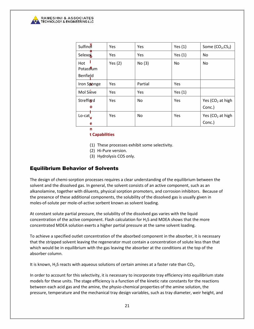
Table IV represents the solvent capabilities4.
Solvent Meets
ppmv,
H2S
emoves
Mercap.
COS, Sulfur
Selective
H2S
emoval
Solution
Degraded by
MEA Yes Partial No Yes (COS,CO2,
CS2)
DEA Yes Partial No Some (COS,
CO2,
CS2)
DGA Yes Partial No Yes (COS,CO2,
CS2)
MDEA Yes Partial Yes (1) No
21
T
a
b
l
e
I
V
-
S
o
l
v
e
n
t Capabilities
(1) These processes exhibit some selectivity.
(2) Hi-Pure version.
(3) Hydrolysis COS only.
Equilibrium Behavior of Solvents
The design of chemi-sorption processes requires a clear understanding of the equilibrium between the
solvent and the dissolved gas. In general, the solvent consists of an active component, such as an
alkanolamine, together with diluents, physical sorption promoters, and corrosion inhibitors. Because of
the presence of these additional components, the solubility of the dissolved gas is usually given in
moles-of-solute per mole-of-active sorbent known as solvent loading.
At constant solute partial pressure, the solubility of the dissolved gas varies with the liquid
concentration of the active component. Flash calculation for H2S and MDEA shows that the more
concentrated MDEA solution exerts a higher partial pressure at the same solvent loading.
To achieve a specified outlet concentration of the absorbed component in the absorber, it is necessary
that the stripped solvent leaving the regenerator must contain a concentration of solute less than that
which would be in equilibrium with the gas leaving the absorber at the conditions at the top of the
absorber column.
It is known, H2S reacts with aqueous solutions of certain amines at a faster rate than CO2.
In order to account for this selectivity, it is necessary to incorporate tray efficiency into equilibrium state
models for these units. The stage efficiency is a function of the kinetic rate constants for the reactions
between each acid gas and the amine, the physio-chemical properties of the amine solution, the
pressure, temperature and the mechanical tray design variables, such as tray diameter, weir height, and
Sulfinol Yes Yes Yes (1) Some (CO2,CS2)
Selexol Yes Yes Yes (1) No
Hot
Potassium
Benfield
Yes (2) No (3) No No
Iron Sponge Yes Partial Yes
Mol Sieve Yes Yes Yes (1)
Strefford Yes No Yes Yes (CO2 at high
Conc.)
Lo-cat Yes No Yes Yes (CO2 at high
Conc.)

22
weir length. The Murphree Efficiency Equation is known as the most common approach to design the
amine units as well as the equilibrium solubility and phase enthalpy.
Vapor-phase enthalpy is calculated by the Pen-obinson Equation of State, which integrates ideal gas-
heat capacity data from a reference temperature liquid-phase enthalpy, and also includes the effect of
latent heat of vaporization and heat of reaction.
The absorption or desorption of H2S and CO2 in amine solutions involves a heat effect due to the
chemical reaction. This heat effect is a function of amine type and concentration and the mole loading
of acid gases. The heat of solution of acid gases is usually obtained by differentiating the experimental
solubility data using a form of the Gibbs-Helmholtz Equation. The heat effect results from evaporation
and condensation of amine and water in both the absorber and regenerator of liquid enthalpy. Water
content of the sour water gas feed can have a dramatic effect on the predicted temperature profile in
the absorber and should be considered especially at low pressures.

23
Fig
ure
3,
Ty
pic
al
Ph
ys
ica
l S
olv
en
t C
on
fig
ura
tio
n
H2S
AB
S.
CO
2 A
BS
.
SA
LE
SG
AS
H2S
RE
Cyl
DR
UM
L/R
EX
CH
AN
GE
R
LP
C
LP
S
NO
. 1
CO
2R
EC
YC
LE
FL
AS
HD
RU
M
NO
. 2
CO
2R
EC
YC
LE
FL
AS
HD
RU
M
TO
VE
NT
VE
NT
GA
SF
LA
SH
DR
UM
AG
T
O S
RU
FE
ED
GA
S
FIL
TE
RS
EP
AR
AT
OR
CH
ILL
ER
/R
EF
RIG
ER
AT
OR
CH
ILL
ER
/R
EF
RIG
ER
AT
OR

24
Software
The commercial simulation software provided by Hysim/ Hysis, D.B. obinson, and Tsweet, is widely
used in the gas processing industry. All three programs use thermodynamic models that Kent and
Eisenberg develop it. However, each one has been fitted using proprietary data as well. Therefore, the
result of each simulator might be different for the same case. All listed commercial programs claims that
are able to handle any type of generic amine design, but sometimes will not have the same results or
even it is not possible to use them as a suitable tool to solve the entire problem. Therefore, it is wise to
use engineering judgment and to design a gas plant, to meet all gas treating design aspects.
Typical Product Specifications
Table V represents the typical product specifications for refining, gas processing, and tail gas-treating
plants.
Table V- Typical Product Specifications
Refining Gas Processing Tail Gas Treating
Fuel gas treating : 50 to
100 ppmv
CO2 LNG Plant: 50
ppmv
H2S USA: 10 ppmv
LPG: copper strip CO2 General: 2% vol H2S General: 150 to 200
ppmv
H2S : 1 to 4 ppmv
Tendency to Foam at High Concentration
If foaming occurs, it is often caused by some alien compound being introduced into the system, such as
a corrosion inhibitor being injected at the wellhead. Other root causes could be pipeline liquids and
solids entering the amine system through an ineffective, raw-gas preconditioning system, contaminants
in the circulation amine, or dissolved amine degradation products and additives in the system.
Operational problems with amines, including excessive losses, foaming, corrosion, hydrogen cracking
and blistering, are symptoms of poor performance, which can be traced to the accumulation of amine
heat-stable salts. The ion exchange-based process removes both the heat stable salts anions and any
metalcations from any amine system.
Foaming in an amine sweetening process can result in a number of different problems, (e.g. reduced
plant gas, decreased efficiency, specifications cannot be met, and amine losses).
Foaming could be caused from suspended solids, condensed hydrocarbons, amine degradation
products, and overheating of amine or any foreign material such as makeup water, corrosion inhibitor,
etc.

25
Silicon-based, and a few other types of antifoam agents, have been found to work reasonably well in
many cases. Antifoams are surface-active molecules that change the surface tension of liquid to reduce
foaming. In addition, the solution should be kept clean by using adequate mechanical and carbon
filtration, carbon should be changed when it is spent, heat stable salts should be prevented from
building up, and proper metallurgy should be selected.
Corrosion in Amine Unit
Corrosion in amine units (especially in DEA units) needs very special attention for the repair of existing
equipment as well as inspection of the entire unit with the following procedures:
• Initial inspection of repaired equipment
• e-inspection of undamaged equipment
• Equipment and piping requiring examination
• Examination and procedures and methods
• Wet-fluorescent magnetic-particle testing
• Dry magnetic-particle testing
• Shear-wave ultrasonic testing
• Visual testing
• Visual testing
• Surface preparation
For amine units, PWHT is recommended for all carbon steel equipment, including piping, exposed to
amine at service temperature of 180 ° F and higher. Not only the maximum operating temperature but
also effect of heat tracing and steam-out on the metal temperature of components in contact with the
amine should be considered.
Industry experience has shown that many reported instances of ASCC in DEA units have occurred in non-
PWHT carbon steel equipment exposed to temperatures higher than 180 0F. However, some cracking
problems have been reported in DEA units at temperatures below this value.
In some cases, equipment including piping has been known to crack during steam-out, owing to the
presence of amine. Each user company should evaluate the need for PWHT at temperatures below 180 °
F in equipment such as absorbers and contactors.
MEA degrades to form acidic and basic products.
Acidic degradation forms multi-acids and eventually reacts with bases to form heat-stable salts, which
are removed by carbon filtration; however, acids cause corrosion. To reduce or prevent corrosion,
remember to consider the following items:
• Keep contaminants out of unit
• Use filtration, wash feed
• Select adequate metallurgy
26
• Avoid buildup to heat-stable salts
• Design to limit reboiler tube temperatures
• Limit flow velocities
• Avoid air ingress
• The acid gas composition leaving the acid gas removal has an impact on sulfur recovery efficiency.
If the H2S concentration of gas to the sulfur recovery unit is low, the acid gas enrichment unit is
recommended. H2S, hydrocarbons, and ammonia content would establish the criteria for sulfur recovery
designs and efficiency and to overcome the remaining impurities that heritage from acid gas processing.
The conventional sulfur plant could be converted to the oxygen enrichment to process more sour gas
and to destroy the impurities require the higher temperature for destruction at the same time. If the
solvent in the existing gas plant has been changed in order to process more acid gas, the downstream
units such as the SU/TGU need some equipment modifications for capacity expansion. In general
commercially available technologies offer three levels of oxygen enrichment: low-level (up to 28%),
medium-level (up to 45%), and high-level (up to 100%) providing additional capacity of about 25%, 75%,
and 150% respectively. All of the existing major equipment can be reused for low-level oxygen
enrichment. For medium-level oxygen enrichment a specially designed burner is needed. High-level
oxygen enrichment requires the implementation of technology staged or recycle process. The process
involves the addition of a new reaction furnace burner, reaction furnace, and waste heat boiler
upstream of the existing equipment. The solvent in the tail gas unit could also be converted to a more
selective solvent, in order to be capable of processing more acid gas. The process involves the addition
of a new quench circulation pump; quench water cooler, and an amine cooler, to increase the cooling
duty. Otherwise, all of the existing major equipment can be reused.
Using oxygen enrichment with the proper burner design for ammonia and BTEX destruction would allow
the burner to operate with the higher temperature and would destroy the undesired elements. It might
be required to convert the catalyst to TiO2 to destroy the impurities such as COS/CS2.
The design criteria for sulfur recovery units could be the following:
• Higher air/oxygen demand
• Dilution effect on Claus equilibrium
• Dilution effect on vapor loss
• COS/CS2 loss (TiO2 & BS)
The emission level is pending on the selection criteria of the sulfur recovery designs and the tail gas
treating in terms of the oxygen enrichment level and the selection of the special solvent, respectively, to
achieve SO2, CO, NOX, and H2S (10 ppmv max) to the acceptable level.
The operating cost and sulfur product quality is ultimately based on the following items:
• Chemical consumption amine vs. liquid edox
• Catalyst requirement (TiO2 & others)
• Byproducts (water & steam)

27
• Contaminants (liquid edox, bio processes)
• Access to means of disposal (agricultural use & blend-away in a large pool)
Figure 4 represents the sulfur recovery efficiency based on dry H2S content.
The dry H2S content could be calculated prior to design of the sulfur recovery units.
Figure 4 – H2S Content VS. SRU Recovery
Revamp Options
The acid gas processes, sulfur recovery units, and the tail gas units could be evaluated in terms of
reconfigurations, and economic impact to meet the new requirements and increase the capacity as
follows:
• Transition from generic to proprietary solvents in acid gas removal
• Transition from air to oxygen in sulfur recovery units, to increase the capacity and destroy NH3,
BTEX, and heavy hydrocarbons
• econfigure catalyst in the reactors
• Transition from generic to proprietary solvents in tail gas units
• Increase the amine concentration to process more feed gas
• Evaluation of the existing equipment
• Evaluation of the existing plot plan for any addition of the new equipment
• Converting from Strefford Process to amine process
References
90
92
94
96
98
0 10 20 30 40 50 60 70 80 90 100
Reco
very
, %
H2S Content, % dry
28
1. Process Screening and Selection for efinery Acid Gas emoval
Processing, Gupta, and S.., et. al., Energy Progress, 6:4, pp. 239-
47, December, 1986
2. Tertiary Ethanolamines More Economical for emoval of H2S and
CO2, iesenfeld, F.D., et. al., Oil & Gas Journal, pp. 61-65,
September 29, 1986
3. Modeling acid gas treating by using AG physical solvents, Don D.
Zhang Presented at Laurence eid Conference 1999.
4. Gas Processors Suppliers Association, 10th
edition, Volume 2,
Section 21


![Hobas GRP pipe systems PN 1 - Amiblu · 2020. 6. 10. · Jacking Pipe PN 1 de [mm] SN SN SN SN SN SN SN SN SN SN SN SN Coupling Type 32000 40000 50000 64000 80000 100000 128000 160000](https://img.dokumen.tips/doc/110x75/61236c822e9bd427c4013216/hobas-grp-pipe-systems-pn-1-amiblu-2020-6-10-jacking-pipe-pn-1-de-mm-sn.jpg)

![OTMguide Screens v3.ppt [Read-Only]...HTML Document, 790 bytes com.au Paint (RFU) in duding Con s umables Refinish GU C] N/S,F GU GU GU C] NSF GU C] N/S,F GU Paint Onh Hours Repair](https://img.dokumen.tips/doc/110x75/5e823631d11dde0c3b540dc3/otmguide-screens-v3ppt-read-only-html-document-790-bytes-comau-paint-rfu.jpg)


![jL/]Gb|gu/ gu/kflnsf :yfgLo /fhkq](https://img.dokumen.tips/doc/110x75/6271c26f6eef2f252a0b912c/jlgbgu-gukflnsf-yfglo-fhkq.jpg)

