Embed Size (px)
Citation preview

Gas Pressures – FAQs
Squire Energy provide gas pressure data with our gas meter solutions. This information is intended for use by the downstream (outlet) designer to complete their design for the outlet pipework and appliances and ensures integrity of the whole system as all designs and installations must be in accordance with the Gas Safety (Installation and Use) Regulations. Based upon our experience we provide answers to some of the most frequently asked questions below:
1. “Why only 19 mbar inlet pressure and 15 mbar outlet pressure?”
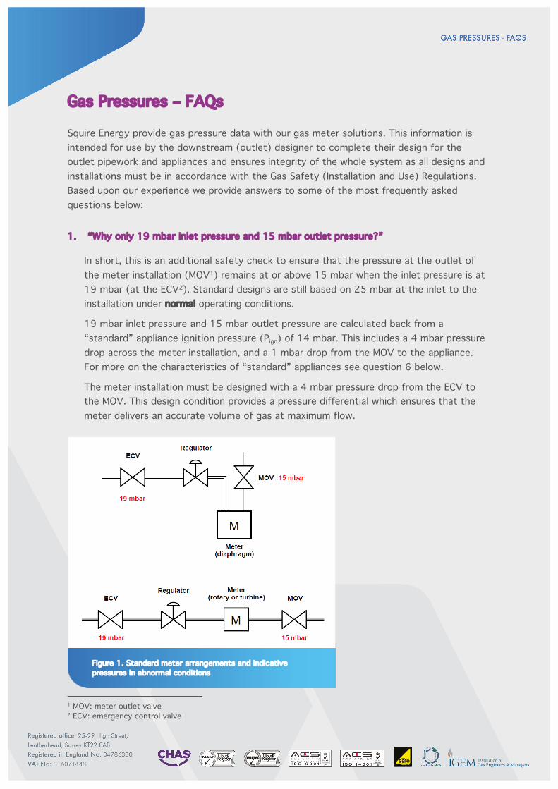
In short, this is an additional safety check to ensure that the pressure at the outlet of the meter installation (MOV1) remains at or above 15 mbar when the inlet pressure is at 19 mbar (at the ECV2). Standard designs are still based on 25 mbar at the inlet to the installation under normal operating conditions.
19 mbar inlet pressure and 15 mbar outlet pressure are calculated back from a “standard” appliance ignition pressure (Pign) of 14 mbar. This includes a 4 mbar pressure drop across the meter installation, and a 1 mbar drop from the MOV to the appliance. For more on the characteristics of “standard” appliances see question 6 below.
The meter installation must be designed with a 4 mbar pressure drop from the ECV to the MOV. This design condition provides a pressure differential which ensures that the meter delivers an accurate volume of gas at maximum flow.
1 MOV: meter outlet valve 2 ECV: emergency control valve
Figure 1. Standard meter arrangements and indicative pressures in abnormal conditions
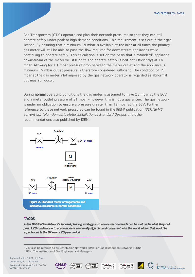
Gas Transporters (GTs3) operate and plan their network pressures so that they can still operate safely under peak or high demand conditions. This requirement is set out in their gas licence. By ensuring that a minimum 19 mbar is available at the inlet at all times the primary gas meter will still be able to pass the flow required for downstream appliances while continuing to operate safely. This calculation is set on the basis that a “standard” appliance downstream of the meter will still ignite and operate safely (albeit not efficiently) at 14 mbar. Allowing for a 1 mbar pressure drop between the meter outlet and the appliance, a minimum 15 mbar outlet pressure is therefore considered sufficient. The condition of 19 mbar at the gas meter inlet imposed by the gas network operator is regarded as abnormal but may still occur.
During normal operating conditions the gas meter is assumed to have 25 mbar at the ECV and a meter outlet pressure of 21 mbar – however this is not a guarantee. The gas network is under no obligation to ensure a pressure greater than 19 mbar at the ECV. Further reference to these network pressures can be found in the IGEM4 publication IGEM/GM/6 current ed. `Non-domestic Meter Installations’. Standard Designs and other recommendations also published by IGEM.
*Note: A Gas Distribution Network’s forward planning strategy is to ensure that demands can be met under what they call peak 1:20 conditions – to accommodate abnormally high demand consistent with the worst winter that would be experienced in the UK over a 20-year period.
3 May also be referred to as Distribution Networks (DNs) or Gas Distribution Networks (GDNs) 4 IGEM: The Institution of Gas Engineers and Managers
Figure 2. Standard meter arrangements and indicative pressures in normal conditions
2. “Is it possible to provide a gas meter installation with nil or very
low pressure drop?”
No. As the pressure differential is the motive force required to deliver an accurate volume of gas at a given rate of flow it is not possible to provide an installation with a low pressure drop without adversely affecting the accuracy of the meter and the performance of the regulator.
The regulator is a statutory safety feature providing overpressure protection to the downstream installation. As it operates mechanically, without an external source of power, it needs the pressure differential to function as intended.
There are commonly two types of gas meter – positive displacement (e.g. diaphragm and rotary meters) and inferential (e.g. turbine meters).
Positive Displacement
Totalised “packets” of known volumes pass through the meter.
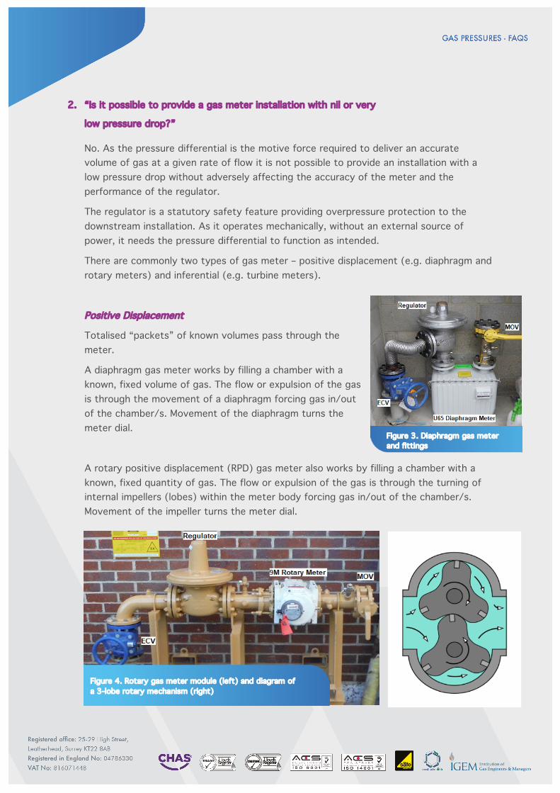
A diaphragm gas meter works by filling a chamber with a known, fixed volume of gas. The flow or expulsion of the gas is through the movement of a diaphragm forcing gas in/out of the chamber/s. Movement of the diaphragm turns the meter dial.
A rotary positive displacement (RPD) gas meter also works by filling a chamber with a known, fixed quantity of gas. The flow or expulsion of the gas is through the turning of internal impellers (lobes) within the meter body forcing gas in/out of the chamber/s. Movement of the impeller turns the meter dial.
Figure 4. Rotary gas meter module (left) and diagram of a 3-lobe rotary mechanism (right)
Figure 3. Diaphragm gas meter and fittings
Inferential
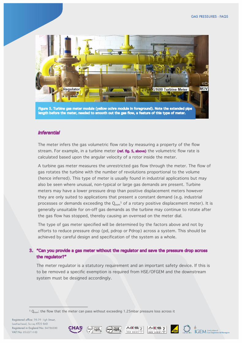
The meter infers the gas volumetric flow rate by measuring a property of the flow stream. For example, in a turbine meter (ref. fig. 5, above) the volumetric flow rate is calculated based upon the angular velocity of a rotor inside the meter.
A turbine gas meter measures the unrestricted gas flow through the meter. The flow of gas rotates the turbine with the number of revolutions proportional to the volume (hence inferred). This type of meter is usually found in industrial applications but may also be seen where unusual, non-typical or large gas demands are present. Turbine meters may have a lower pressure drop than positive displacement meters however they are only suited to applications that present a constant demand (e.g. industrial processes or demands exceeding the Qnom
5 of a rotary positive displacement meter). It is generally unsuitable for on-off gas demands as the turbine may continue to rotate after the gas flow has stopped, thereby causing an overread on the meter dial.
The type of gas meter specified will be determined by the factors above and not by efforts to reduce pressure drop (pd, pdrop or Pdrop) across a system. This should be achieved by careful design and specification of the system as a whole.
3. “Can you provide a gas meter without the regulator and save the pressure drop across the regulator?”
The meter regulator is a statutory requirement and an important safety device. If this is to be removed a specific exemption is required from HSE/OFGEM and the downstream system must be designed accordingly.
5 Qnom: the flow that the meter can pass without exceeding 1.25mbar pressure loss across it
Figure 5. Turbine gas meter module (yellow ochre module in foreground). Note the extended pipe length before the meter, needed to smooth out the gas flow, a feature of this type of meter.
4. “In the past we have previously been given general assurances that we’ll get 21 mbar at the meter outlet”
This is a common misconception. No-one is or was ever able to provide such an assurance. Pressures fluctuate in the system throughout the day and throughout the year, especially in Winter where demand is significantly higher. Whilst the pressure at the inlet to a meter can be high enough to permit a pressure of 21mbar at the meter outlet (under optimal conditions) there is not a statutory requirement for this to be maintained at all times. As stated in the answer to question 1, The GT (as the owner/operator of the gas network), has no obligation under their licence to guarantee anything other than 19 mbar at the ECV. Any guarantee you may receive from any party that confirms >19 mbar at the inlet to the primary meter (at the ECV), on a standard or Low Pressure (LP) gas network should be regarded with extreme caution.
With gas meters provided by Squire Energy our information sheet describes the pressure parameters that we have used for our design, in accordance with specifications within the UK gas industry and in accordance with the recommendations of IGEM and the operating policy of the relevant GT.
5. “What pressure drop should I use when determining the installation (outlet) pipework design?”
A competent engineer should determine this but the IGEM publication IGE/UP/2 current ed. `Installation Pipework on Industrial and Commercial Premises …` states that for natural gas, where the operating pressure (OP) is <25 mbar, the maximum design pressure drop at the maximum design flow should not exceed 1.0 mbar. For OP >25 mbar the maximum design pressure drop at the maximum design flow should not exceed 10% of the OP. Maximum (unfiltered) gas velocity should not exceed 20 m/s.
6. “Our M&E installer has stated that they require 21 mbar at the appliances”
If your installer maintains that elevated pressures are required at the inlet to the appliance then you may have to consider the provision of a gas booster/compressor – see questions 7 and 8 below.
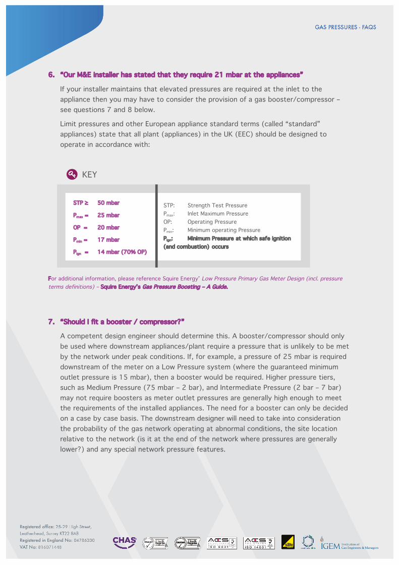
Limit pressures and other European appliance standard terms (called “standard” appliances) state that all plant (appliances) in the UK (EEC) should be designed to operate in accordance with:
For additional information, please reference Squire Energy’ Low Pressure Primary Gas Meter Design (incl. pressure terms definitions) – Squire Energy’s Gas Pressure Boosting – A Guide.
7. “Should I fit a booster / compressor?”
A competent design engineer should determine this. A booster/compressor should only be used where downstream appliances/plant require a pressure that is unlikely to be met by the network under peak conditions. If, for example, a pressure of 25 mbar is required downstream of the meter on a Low Pressure system (where the guaranteed minimum outlet pressure is 15 mbar), then a booster would be required. Higher pressure tiers, such as Medium Pressure (75 mbar – 2 bar), and Intermediate Pressure (2 bar – 7 bar) may not require boosters as meter outlet pressures are generally high enough to meet the requirements of the installed appliances. The need for a booster can only be decided on a case by case basis. The downstream designer will need to take into consideration the probability of the gas network operating at abnormal conditions, the site location relative to the network (is it at the end of the network where pressures are generally lower?) and any special network pressure features.
STP: Strength Test Pressure Pmax: Inlet Maximum Pressure OP: Operating Pressure Pmin: Minimum operating Pressure Pign: Minimum Pressure at which safe ignition (and combustion) occurs
STP ≥ 50 mbar
Pmax = 25 mbar
OP = 20 mbar
Pmin = 17 mbar
Pign = 14 mbar (70% OP)
KEY
Boosters or compressors should not be considered as a solution to overcome incorrectly (undersized) downstream installation pipework.
The designer should also consult with their M&E installer and appliance manufacturer to verify the minimum required inlet working pressures to the gas appliances to be installed. The final decision whether to install a booster/compressor etc. rests with the designer and not Squire Energy.
It is not good practice to retro-fit a booster/compressor (or to install “non-standard” or “non-typical” equipment) if the system has not been designed to accommodate it. Retro-fitting a booster/ compressor post-construction, without prior notification or approval, could render the entire gas installation as “unfit for purpose” and potentially unsafe.
For additional information, please reference Squire Energy’ Gas Pressure Boosting – A Guide or IGEM GM/6 current ed. `Non-domestic meter installations – Standard Designs.
Further reading can also be found at
http://pwemag.co.uk/news/fullstory.php/aid/1586/When_gas_pressure_needs_a_boost.html (“When gas pressure needs a boost” by Bernard Dawson, Technical Director of Riello).
8. “We have decided / our M&E installer has advised us that a booster / compressor is required / proposed. What information do I need to provide to Squire Energy to ensure that the proposed new gas connection, offtake and primary gas meter is designed (and subsequently installed) correctly to meet my requirements?”
Should you opt to install any booster, compressor or “non-standard” or “non-typical” plant or equipment or are aware of any “non-typical” heating or gas loads, demands or plant operating profiles or design parameters that are considered non-typical Squire Energy should be informed when the request is submitted for the quotation for any new offtake, primary gas meter works etc.
You should provide the following information to Squire Energy prior to the preparation and production of the quotation / estimate by us to ensure that any network analysis (by the GT or 3rd party or Squire Energy) is carried out correctly thereby ensuring all on-site plant requirements are taken in to account:
§ Volume of gas the booster is required to handle (“max plant flow rate”) in kW / SCMH6
§ Maximum pressure lift proposed in mbar § Minimum flow rate § Booster / compressor “ramp rate” - time taken (seconds) to reach full load from
start up § Crash stop – time taken (seconds) from max flow rate / max elevated pressure
to zero flow rate / zero pressure elevation
6 SCMH: standard cubic meters per hour
If we are only made aware of non-typical loads or non-typical equipment being proposed after a quotation has been accepted this will negate any previous design works or offer of works or services. A new quotation / estimate and associated design, review and approval (by the GT) will then be required to ensure the correct design and plant operating information is included and to make sure that the GT’ gas network has sufficient available pressure and capacity and that any connection, offtake (mains/services), termination and primary gas meter is correct and fit for purpose.
The minimum required information above should be provided to Squire Energy by the customer or their nominated advisor or 3rd party agent prior to the preparation of the quotation or any design work by Squire Energy. For ease of use we have developed a `Non-typical Demand Form` which is available upon request. Given the factors that can influence the correct performance of a gas booster and the gas utilisation plant there are clear benefits to seeking specialist input when getting involved with this highly complex area. Squire Energy is not a manufacturer or supplier of specialist booster plant or utilisation plant or equipment and we recommend that the customer and their installer seek out such specialist expert services as necessary and as required.
For additional information, please reference Squire Energy’s Gas Pressure Boosting – A Guide.

Acknowledgements
—
We are very fortunate at Squire Energy to have a team of managers, operatives and engineers with many years’ experience and knowledge gained from working in the gas and construction industry; both in the upstream and downstream areas as specifiers and designers, installers and problem solvers. We have unashamedly tapped in to this resource to help compile this guide.
However, we appreciate and acknowledge the invaluable assistance, recommendations and guidance which we have accessed and referred to, in particular the gas industry practices and recommendations published by The Institution of Gas Engineers and Managers (IGEM - http://www.igem.org.uk/). We would also like to acknowledge the specialist and expert advice from various manufacturers and suppliers to the industry and we recommend that the customer and their installer seek out such specialist advice from these and other expert parties.
Disclaimer
—
This document/guidance/note/advisory information is intended for general guidance purposes only and is not offered as any instruction or as a full or exhaustive list and is intended for general guidance purposes only. This document is not intended as a replacement for any legislation, legislative guidance, ACoPs or manufacturers instruction or interpretation of any and all such information. Reference should be made to appropriate Institution of Gas Engineers and Managers published recommendations, British Standards, UK/EU legislation, ACoPs, appropriate and other industry guidelines, recognised good working practice and policy and recommendations where made by the appropriate Gas Transporter, Meter Asset Manager, Approved Meter Installer, plant supplier or manufacturer or any other relevant 3rd party.
The contents therein remain the intellectual property of Squire Energy and may not be copied, shared or circulated without first obtaining our prior permission. Any information relating to `customer guidance`/`guidance`/`note`/`advisory information` or `additional information` contained within or which may be attached to any correspondence by Squire Energy or subsequently forwarded is provided for assistance, guidance and general information purposes only.
Squire Energy, its employees or agents will not be held responsible for accuracy (or inaccuracies), provenance or for any outcome or any loss whatsoever, however arising from its use (or misuse) or interpretation or reliance on such information. Whilst Squire Energy makes every attempt to ensure the accuracy and reliability of the information provided this should not be relied upon as replacement of or interpretation of legislation, a replacement of or substitute for formal or legal advice, interpretation of legislation or intended to suggest that any party should not also obtain guidance from any originating body or bodies or 3rd party, manufacturer, supplier, appropriate department of the Local Authority, County or Borough Council and / or their partners or any associates or any specialists, legal advisors or reference to UK/EU legislation, as these shall all take precedence.