Embed Size (px)
Citation preview
GAS METER BOX LOCATION HANDBOOK (FOR GAS METER SIZES AL8 TO AL18) GAS DIVISION
Document No: AGA-A&C-MA03 Revision No: 9 Issue Date: 20/03/2019
GAS METER BOX LOCATION HANDBOOK (FOR GAS METER SIZES AL8 TO AL18)
Document No: AGA-A&C-MA03
Revision No: 9
Issue Date: 20/03/2019 Page i of 53
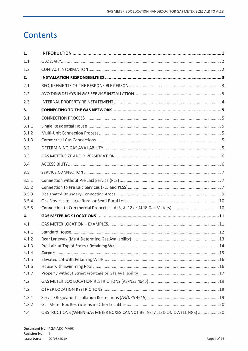
Contents
1. INTRODUCTION ....................................................................................................................... 1
1.1 GLOSSARY ........................................................................................................................................... 2
1.2 CONTACT INFORMATION ................................................................................................................... 2
2. INSTALLATION RESPONSIBILITIES ............................................................................................. 3
2.1 REQUIREMENTS OF THE RESPONSIBLE PERSON ................................................................................ 3
2.2 AVOIDING DELAYS IN GAS SERVICE INSTALLATION ........................................................................... 3
2.3 INTERNAL PROPERTY REINSTATEMENT ............................................................................................. 4
3. CONNECTING TO THE GAS NETWORK ....................................................................................... 5
3.1 CONNECTION PROCESS ...................................................................................................................... 5
3.1.1 Single Residential House .................................................................................................................... 5
3.1.2 Multi-Unit Connection Process .......................................................................................................... 5
3.1.3 Commercial Gas Connections ............................................................................................................ 5
3.2 DETERMINING GAS AVAILABILITY ...................................................................................................... 5
3.3 GAS METER SIZE AND DIVERSIFICATION ............................................................................................ 6
3.4 ACCESSIBILITY ..................................................................................................................................... 6
3.5 SERVICE CONNECTION ....................................................................................................................... 7
3.5.1 Connection without Pre Laid Service (PLS) ........................................................................................ 7
3.5.2 Connection to Pre Laid Services (PLS and PLSS) ................................................................................. 7
3.5.3 Designated Boundary Connection Areas ........................................................................................... 9
3.5.4 Gas Services to Large Rural or Semi-Rural Lots ................................................................................ 10
3.5.5 Connection to Commercial Properties (AL8, AL12 or AL18 Gas Meters) ......................................... 10
4. GAS METER BOX LOCATIONS .................................................................................................. 11
4.1 GAS METER LOCATION – EXAMPLES ................................................................................................ 11
4.1.1 Standard House ................................................................................................................................ 12
4.1.2 Rear Laneway (Must Determine Gas Availability)............................................................................ 13
4.1.3 Pre-Laid at Top of Stairs / Retaining Wall ........................................................................................ 14
4.1.4 Carport ............................................................................................................................................. 15
4.1.5 Elevated Lot with Retaining Walls .................................................................................................... 16
4.1.6 House with Swimming Pool ............................................................................................................. 16
4.1.7 Property without Street Frontage or Gas Availability ...................................................................... 17
4.2 GAS METER BOX LOCATION RESTRICTIONS (AS/NZS 4645) ............................................................. 19
4.3 OTHER LOCATION RESTRICTIONS..................................................................................................... 19
4.3.1 Service Regulator Installation Restrictions (AS/NZS 4645) .............................................................. 19
4.3.2 Gas Meter Box Restrictions in Other Localities ................................................................................ 20
4.4 OBSTRUCTIONS (WHEN GAS METER BOXES CANNOT BE INSTALLED ON DWELLINGS) .................. 20
GAS METER BOX LOCATION HANDBOOK (FOR GAS METER SIZES AL8 TO AL18)
Document No: AGA-A&C-MA03
Revision No: 9
Issue Date: 20/03/2019 Page ii of 53
5. GAS METER BOX INSTALLATION REQUIREMENTS .................................................................... 22
5.1 REQUIREMENTS ............................................................................................................................... 22
5.1.1 AL8 Gas Meter Box (Partially Recessed or face mounted) ............................................................... 22
5.1.2 AL12 Gas Meter Box (Partially Recessed or face mounted) ............................................................ 22
5.1.3 AL8 Dual Gas and Electric Meter Box (Partially Recessed or face mounted) .................................. 23
5.1.4 AL12 Dual Gas and Electric Meter Box (Partially Recessed or face mounted) ................................ 23
5.1.5 Multi-Unit Gas Meter Boxes (Partially Recessed or Face Mounted) ............................................... 23
5.1.6 Gas Meter Box (Fully Recessed) ....................................................................................................... 24
5.2 GAS METER BOX MOUNTED ON WALLS .......................................................................................... 25
5.2.1 Gas Meter Boxes on Nib Walls (Recommended Alternative Gas Meter Box Position) ................... 25
5.2.2 Gas Meter Boxes on Freestanding Walls ......................................................................................... 25
5.2.3 Gas Service Riser and Footing Requirements .................................................................................. 27
5.3 LOCATING A GAS METER BOX AWAY FROM OPENINGS INTO A BUILDING ..................................... 28
5.3.1 Window within Gas Meter Box Exclusion Zone ............................................................................... 28
5.4 GAS METER BOXES MOUNTED ADJACENT TO ELECTRICAL POWER DOMES ................................... 29
5.5 GAS METER BOXES MOUNTED ADJACENT TO SOURCE OF IGNITION .............................................. 29
5.6 PROTECTION FOR GAS METERS ....................................................................................................... 30
5.7 SECURITY FOR GAS METER BOX AND ENCLOSURE .......................................................................... 31
5.7.1 Viewing Apertures for Locked Enclosures ........................................................................................ 31
5.7.2 Mandatory Lock Requirements ........................................................................................................ 31
6. GAS METER BANKS AND ENCLOSURES .................................................................................... 33
6.1 MULTI-UNIT GAS METER BOXES ...................................................................................................... 33
6.2 BANKS OF GAS METER BOXES .......................................................................................................... 33
6.3 BANKS OF GAS METERS MOUNTED ON AGA APPROVED BRACKETS IN BUILDING RECESSES .......................................................................................................................................... 35
6.3.1 Depth and Height of Recesses ......................................................................................................... 35
6.3.2 Inside the Recess .............................................................................................................................. 36
6.4 GAS METERS IN RECESSES (ENCLOSURES) ....................................................................................... 36
6.5 DOORS AND VENTILATION ............................................................................................................... 37
6.6 FLOOR FINISHES ............................................................................................................................... 38
6.7 SECURITY ACCESS ............................................................................................................................. 38
6.8 SIGNAGE ........................................................................................................................................... 38
7. RELATED DOCUMENTS ........................................................................................................... 39
8. DISCLAIMER ........................................................................................................................... 40
9. DOCUMENT APPROVAL ......................................................... ERROR! BOOKMARK NOT DEFINED.
10. DOCUMENT HISTORY ............................................................ ERROR! BOOKMARK NOT DEFINED.
11. APPENDICES .......................................................................................................................... 41
APPENDIX A. GAS CONNECTION CHECKLIST ....................................................................................... 42
GAS METER BOX LOCATION HANDBOOK (FOR GAS METER SIZES AL8 TO AL18)
Document No: AGA-A&C-MA03
Revision No: 9
Issue Date: 20/03/2019 Page iii of 53
APPENDIX B. GAS SERVICE INSTALLATION ON HOLD FORM ................................................................ 44
APPENDIX C. GAS SAFETY – DOS AND DON’TS ................................................................................... 46
APPENDIX D. FEEDBACK FORM .......................................................................................................... 48
LIST OF FIGURES
Figure 1: Overview – Request for Gas ................................................................................................................................ 5
Figure 2: Gas Meter Selection and Diversity Factors .......................................................................................................... 6
Figure 3 Plan Showing Gas Mains and Pre-Laid Service Locations ..................................................................................... 7
Figure 4 Typical Connection to a Pre-Laid Service .............................................................................................................. 8
Figure 5 Stairways at Front of Properties ........................................................................................................................... 9
Figure 6 Pre-Laid Gas Services Installed Under Stairways (PLSS) ....................................................................................... 9
Figure 7: Legend for Diagrams .......................................................................................................................................... 11
Figure 8 Standard House................................................................................................................................................... 12
Figure 9 Rear Laneway ...................................................................................................................................................... 13
Figure 10 Pre-Laid at Top of Stairs (Double Stairway) ...................................................................................................... 14
Figure 11 Pre-Laid at Top of Stairs (Straight on Single Stairway) ...................................................................................... 14
Figure 12 Carport .............................................................................................................................................................. 15
Figure 13 Elevated Lot with Retaining Walls .................................................................................................................... 16
Figure 14 House with Swimming Pool .............................................................................................................................. 16
Figure 15 Property without Street Frontage or Gas Availability ....................................................................................... 17
Figure 16 Gas Meter Box Installed Above Flight of Stairs (Unacceptable Positions) ........................................................ 21
Figure 17 AL8 Gas Meter Box............................................................................................................................................ 22
Figure 18 AL12 Gas Meter Box.......................................................................................................................................... 22
Figure 19 AL8 Dual Gas and Electric Meter Box ................................................................................................................ 23
Figure 20 AL12 Combined Gas and Electric Meter Box .................................................................................................... 23
Figure 21 AL8 Double and Triple Gas Meter Box .............................................................................................................. 23
Figure 22 Gas Meter Box (Fully Recessed) ........................................................................................................................ 24
Figure 23 Nib Wall ............................................................................................................................................................ 25
Figure 24 Freestanding Wall Housing Gas Meter Box (Example / Reference Only – not for construction) ..................... 26
Figure 25 Footing Cut Away .............................................................................................................................................. 27
Figure 26 Distances from Openings into the Building ...................................................................................................... 28
Figure 27 Permanently Fixing Window within Exclusion Zone ......................................................................................... 29
Figure 28 Distances from Electrical Power Domes ........................................................................................................... 29
Figure 29 Distances from Sources of Ignition ................................................................................................................... 30
Figure 30 Gas Meter Box Protection (Examples) .............................................................................................................. 30
Figure 31 Gas Meter Box Protection (Bollard Diagrams) .................................................................................................. 31
Figure 32 Gas Meter Box Viewing Apertures .................................................................................................................... 31
Figure 33 Double and Triple Gas Meter Boxes ................................................................................................................. 33
Figure 34 AL8 Standard Gas Meter Bank Layout – Gas Meter Boxes ............................................................................... 34
Figure 35 AL8 Non-Standard Gas Meter Bank Layout – Gas Meter Boxes ....................................................................... 34
Figure 36 AL8 Gas Meter Groupings ................................................................................................................................. 35
Figure 37 Acceptable Recess or Enclosure ....................................................................................................................... 36
Figure 38 Recess or Enclosure with Fully Louvered Doors ............................................................................................... 37
GAS METER BOX LOCATION HANDBOOK (FOR GAS METER SIZES AL8 TO AL18)
Document No: AGA-A&C-MA03
Revision No: 9
Issue Date: 20/03/2019 Page 1 of 53
1. INTRODUCTION
ATCO Gas Australia (AGA) owns and maintains the underground network of gas pipelines in Western Australia, bringing natural gas to over 725,000 homes and businesses. This Handbook provides guidance for installing your natural gas meter box and service for safe, reliable and efficient connection to AGA natural gas distribution network.
This document is not to be used for guidance for any works at AGA’s Albany Liquefied Petroleum Gas (LPG) network due to the differences in properties and behaviour between LPG and natural gas. Information provided in this document relates only to installation of AGA’s infrastructure and does not relate to installation of other utility services. Where a combination gas / electrical meter box is to be utilised, the relevant electrical authority’s requirements must also be met.
New developments typically have buildings that occupy a larger portion of the block and there are an increasing number of developments located in elevated positions. The changing designs of these developments can compromise standard gas meter box locations. AGA wishes to avoid delays by providing information to the industry at design stage, eliminating costly alterations and variations during construction.
This Handbook outlines the installation procedures to streamline processes and help avoid delays or additional work and costs being incurred by the requestor.
This Handbook must be considered a “live” document and is therefore subject to change.
The Feedback Form, (refer to Appendix D), can be used to provide improvement suggestions, relating to this document, to AGA.
GAS METER BOX LOCATION HANDBOOK (FOR GAS METER SIZES AL8 TO AL18)
Document No: AGA-A&C-MA03
Revision No: 9
Issue Date: 20/03/2019 Page 2 of 53
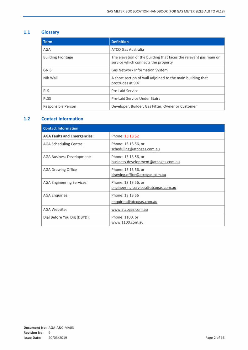
1.1 Glossary
Term Definition
AGA ATCO Gas Australia
Building Frontage The elevation of the building that faces the relevant gas main or service which connects the property
GNIS Gas Network Information System
Nib Wall A short section of wall adjoined to the main building that protrudes at 90º
PLS Pre-Laid Service
PLSS Pre-Laid Service Under Stairs
Responsible Person Developer, Builder, Gas Fitter, Owner or Customer
1.2 Contact Information
Contact Information
AGA Faults and Emergencies: Phone: 13 13 52
AGA Scheduling Centre: Phone: 13 13 56, or [email protected]
AGA Business Development: Phone: 13 13 56, or [email protected]
AGA Drawing Office Phone: 13 13 56, or [email protected]
AGA Engineering Services: Phone: 13 13 56, or [email protected]
AGA Enquiries: Phone: 13 13 56
AGA Website: www.atcogas.com.au
Dial Before You Dig (DBYD): Phone: 1100, or www.1100.com.au
GAS METER BOX LOCATION HANDBOOK (FOR GAS METER SIZES AL8 TO AL18)
Document No: AGA-A&C-MA03
Revision No: 9
Issue Date: 20/03/2019 Page 3 of 53
2. INSTALLATION RESPONSIBILITIES
This section provides information on the restrictions and conditions placed on gas meter box locations. Graphics in Section 4.1 are provided to illustrate both correct and incorrect installations.
2.1 Requirements of the Responsible Person
Caution: It is recommended that the Responsible Person complete the Gas Connection Checklist, (refer to Appendix A).
It is the responsibility of the person requesting a gas service to ensure they are fully aware of the following:
The connection process as detailed in the Connection Process Handbook.
Their responsibilities and obligations to achieve a prompt, efficient service connection that meet the requirements provided within this document.
Specific responsibilities are as follows:
Locate the gas meter box in conforming position.
Provide information and plans for any known location of soak wells, reticulation pipes or other services or below ground obstructions.
Arrange any reinstatement inside the property line including associated costs.
Provide authorisation approval for any excavation inside the property line required to complete the gas connection, i.e., Notice of Acceptance or Gas Service Installation on Hold Form, refer to Appendix B.
Ensure line of service is free from hazards or obstructions (e.g., building material, protruding building footings or vegetation) Ensure gas meter box is installed entirely within the property boundary for the property requiring the gas connection, unless other written arrangements have been accepted by AGA.
Following the installation of the gas service, a gas meter and regulator assembly will be fitted with a security disc located in the gas meter outlet. The consumers’ gas fitter is responsible to commission (introduce gas into) their supply piping downstream of the gas meter.
2.2 Avoiding Delays in Gas Service Installation
Gas service installation may be delayed for a number of reasons and gas service installation may be deferred by placing the installation on hold until the reason for the delay is rectified.
A Gas Service Installation on Hold Form, (refer to Appendix B) will be left in the gas meter box (for new dwellings) or in the consumer letter box, if existing premises.
Examples of situations where delays may occur:
The gas meter box is installed in a non-compliant position:
o Too close to a window that can be opened
GAS METER BOX LOCATION HANDBOOK (FOR GAS METER SIZES AL8 TO AL18)
Document No: AGA-A&C-MA03
Revision No: 9
Issue Date: 20/03/2019 Page 4 of 53
o Meter box installed too high
o Footing requires cutting to accommodate the gas service riser
Paving or driveway is installed beneath gas meter boxes and permission is required in order to remove or lift paving.
Rubble or debris is on the line of service route preventing access for installation.
2.3 Internal Property Reinstatement
Internal property reinstatement refers to any reinstatement and restoration of surfaces inside the property boundary, including but not limited to, paving, driveway and lawns.
If paving or other finished surface must be lifted or removed to install the gas service, then the Responsible Person is responsible for the reinstatement.
For an established premise, it is the gasfitter’s responsibility to obtain the Responsible Person’s signature in the last paragraph of the Gas Service Installation on Hold Form, refer to Appendix B, confirming that they agree to the conditions of the installation. The form must be left in the customer’s gas meter box.
For new connections, the permission letter must be left in the gas meter box.
GAS METER BOX LOCATION HANDBOOK (FOR GAS METER SIZES AL8 TO AL18)
Document No: AGA-A&C-MA03
Revision No: 9
Issue Date: 20/03/2019 Page 5 of 53
3. CONNECTING TO THE GAS NETWORK
This section provides information on the connection process, gas availability, gas meter box accessibility and network connection, including connection to pre-laid services.
3.1 Connection Process
3.1.1 Single Residential House
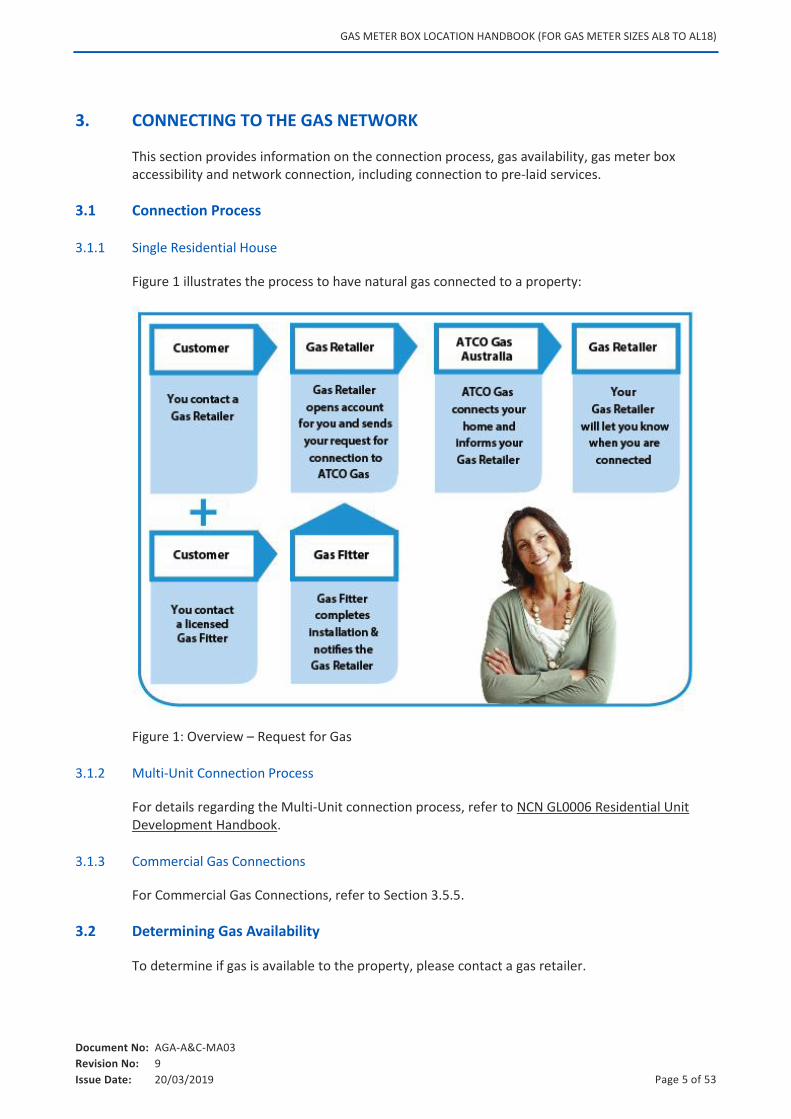
Figure 1 illustrates the process to have natural gas connected to a property:
Figure 1: Overview – Request for Gas
3.1.2 Multi-Unit Connection Process
For details regarding the Multi-Unit connection process, refer to NCN GL0006 Residential Unit Development Handbook.
3.1.3 Commercial Gas Connections
For Commercial Gas Connections, refer to Section 3.5.5.
3.2 Determining Gas Availability
To determine if gas is available to the property, please contact a gas retailer.
GAS METER BOX LOCATION HANDBOOK (FOR GAS METER SIZES AL8 TO AL18)
Document No: AGA-A&C-MA03
Revision No: 9
Issue Date: 20/03/2019 Page 6 of 53
If gas is not outside the property but in an adjoining street, or if there is no appropriate gas main in the vicinity, then a mains extension may be required to bring gas to the property. If requested, a gas retailer will organise a quotation from AGA to extend the gas main to the property.
Where a gas connection cannot readily be made because there is no direct street frontage to a gas main (e.g., a property on a rear laneway without gas mains), refer to Section 4.1.7.
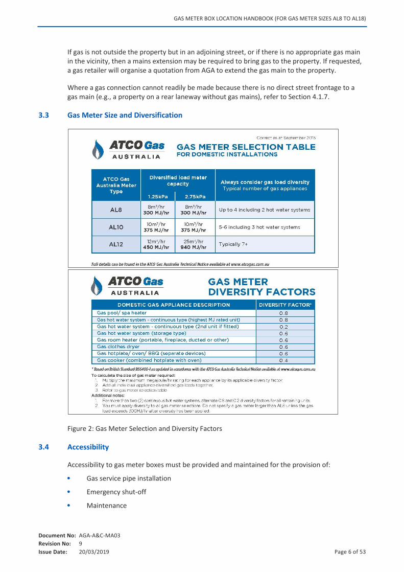
3.3 Gas Meter Size and Diversification
Figure 2: Gas Meter Selection and Diversity Factors
3.4 Accessibility
Accessibility to gas meter boxes must be provided and maintained for the provision of:
Gas service pipe installation
Emergency shut-off
Maintenance
GAS METER BOX LOCATION HANDBOOK (FOR GAS METER SIZES AL8 TO AL18)
Document No: AGA-A&C-MA03
Revision No: 9
Issue Date: 20/03/2019 Page 7 of 53
Gas meter reading
Inspection
A minimum 600mm clearance must be maintained in front of the gas meter box at all times.
3.5 Service Connection
The gas network connection point is normally pre-determined by the location of a Pre-laid Service (PLS) or Pre-laid Service under Stairs (PLSS), prior to selecting an approved gas meter box location.
3.5.1 Connection without Pre Laid Service (PLS)
Where there is no PLS or PLSS, the line of service between the gas meter box and the gas connection point in the roadway is to be considered, ensuring the route is unhindered and free from hazards and obstructions. For additional details refer to Section 4.4.
3.5.2 Connection to Pre Laid Services (PLS and PLSS)
In the majority of new subdivisions a PLS or PLSS is installed in a common trench to the boundary line of a property when the subdivision is developed.
The line of service between the gas meter box and the PLS is to be considered, ensuring the route is unhindered and free from hazards and obstructions. For additional details refer to Section 4.4.
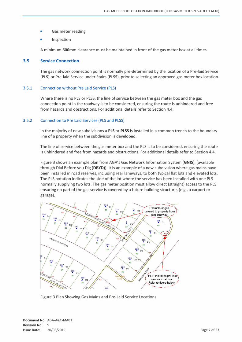
Figure 3 shows an example plan from AGA’s Gas Network Information System (GNIS), (available through Dial Before you Dig (DBYD)). It is an example of a new subdivision where gas mains have been installed in road reserves, including rear laneways, to both typical flat lots and elevated lots. The PLS notation indicates the side of the lot where the service has been installed with one PLS normally supplying two lots. The gas meter position must allow direct (straight) access to the PLS ensuring no part of the gas service is covered by a future building structure, (e.g., a carport or garage).
Figure 3 Plan Showing Gas Mains and Pre-Laid Service Locations
GAS METER BOX LOCATION HANDBOOK (FOR GAS METER SIZES AL8 TO AL18)
Document No: AGA-A&C-MA03
Revision No: 9
Issue Date: 20/03/2019 Page 8 of 53
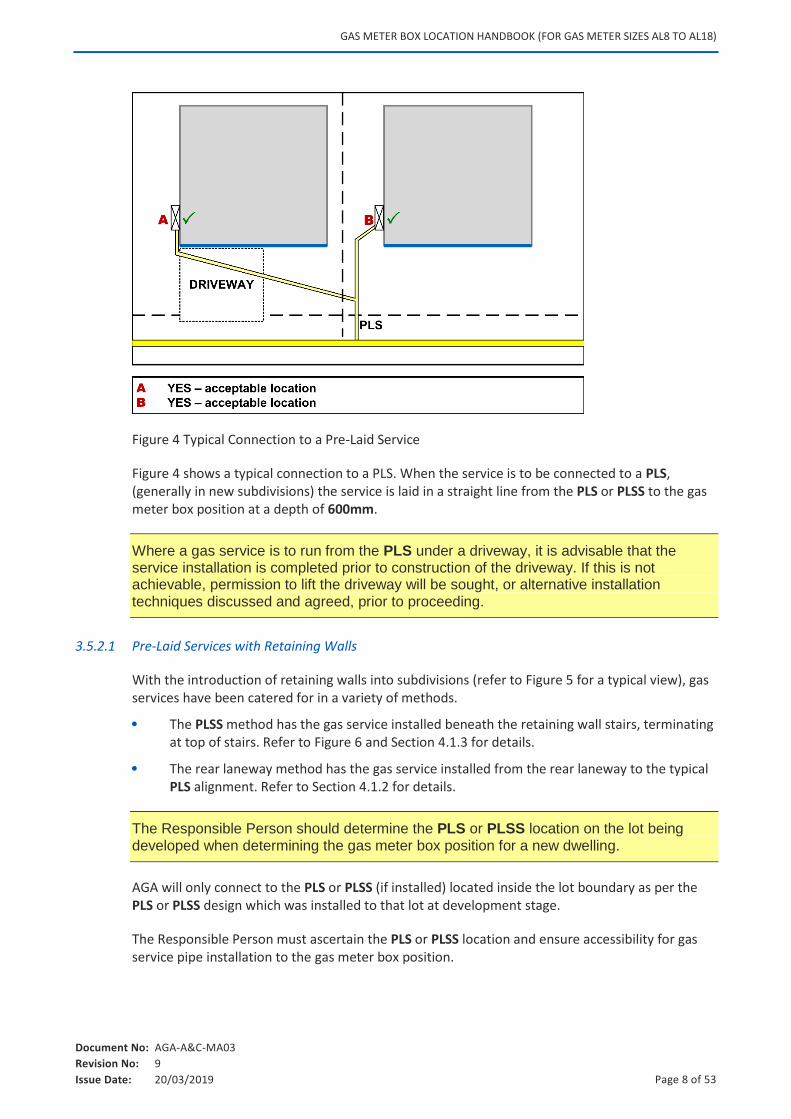
Figure 4 Typical Connection to a Pre-Laid Service
Figure 4 shows a typical connection to a PLS. When the service is to be connected to a PLS, (generally in new subdivisions) the service is laid in a straight line from the PLS or PLSS to the gas meter box position at a depth of 600mm.
Where a gas service is to run from the PLS under a driveway, it is advisable that the service installation is completed prior to construction of the driveway. If this is not achievable, permission to lift the driveway will be sought, or alternative installation techniques discussed and agreed, prior to proceeding.
3.5.2.1 Pre-Laid Services with Retaining Walls
With the introduction of retaining walls into subdivisions (refer to Figure 5 for a typical view), gas services have been catered for in a variety of methods.
The PLSS method has the gas service installed beneath the retaining wall stairs, terminating at top of stairs. Refer to Figure 6 and Section 4.1.3 for details.
The rear laneway method has the gas service installed from the rear laneway to the typical PLS alignment. Refer to Section 4.1.2 for details.
The Responsible Person should determine the PLS or PLSS location on the lot being developed when determining the gas meter box position for a new dwelling.
AGA will only connect to the PLS or PLSS (if installed) located inside the lot boundary as per the PLS or PLSS design which was installed to that lot at development stage.
The Responsible Person must ascertain the PLS or PLSS location and ensure accessibility for gas service pipe installation to the gas meter box position.
GAS METER BOX LOCATION HANDBOOK (FOR GAS METER SIZES AL8 TO AL18)
Document No: AGA-A&C-MA03
Revision No: 9
Issue Date: 20/03/2019 Page 9 of 53
If a gas meter box is located in a position which may become inaccessible, then AGA will not approve the connection.
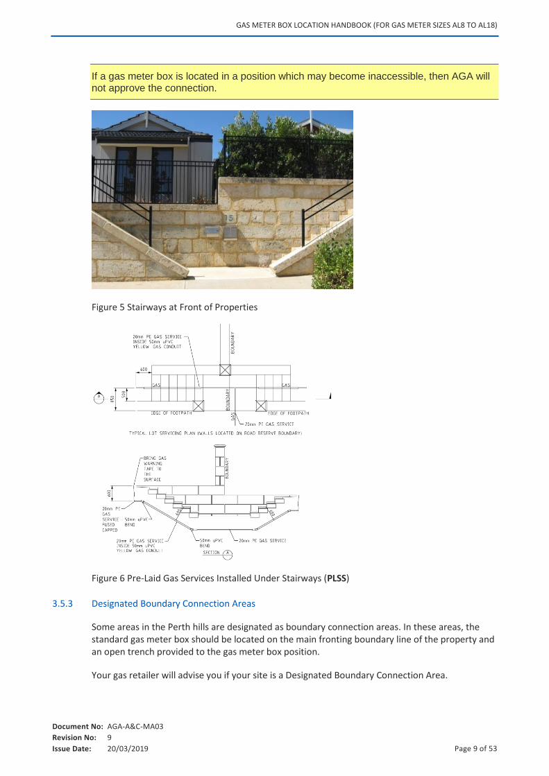
Figure 5 Stairways at Front of Properties
Figure 6 Pre-Laid Gas Services Installed Under Stairways (PLSS)
3.5.3 Designated Boundary Connection Areas
Some areas in the Perth hills are designated as boundary connection areas. In these areas, the standard gas meter box should be located on the main fronting boundary line of the property and an open trench provided to the gas meter box position.
Your gas retailer will advise you if your site is a Designated Boundary Connection Area.
GAS METER BOX LOCATION HANDBOOK (FOR GAS METER SIZES AL8 TO AL18)
Document No: AGA-A&C-MA03
Revision No: 9
Issue Date: 20/03/2019 Page 10 of 53
3.5.4 Gas Services to Large Rural or Semi-Rural Lots
The gas meter box should be mounted on the main fronting boundary line of the property. Alternatively, it may be mounted on the primary building in a suitable, compliant position. Additional charges may apply for services over 20m in length.
All the following conditions must be met:
A suitable straight and direct trench is to be provided from the boundary to the gas meter location by the Responsible Person.
The route shall, as far as practicable, be at right angles to the gas main or as directed by AGA.
The bed of the trench shall be soil that is free from rock or other sharp formation that may cause damage to the Polyethylene (PE) gas service pipe.
The minimum depth of cover is 600mm.
A front boundary connection is the preferred option when the Building Frontage is greater than 20m from the boundary line.
3.5.5 Connection to Commercial Properties (AL8, AL12 or AL18 Gas Meters)
For a new gas connection to a commercial property requiring an AL8 or AL12 gas meter, refer to the Connection Process Handbook.
Installation of an AL18 gas meter, or greater, requires a Commercial Gas Request (CGR) to be submitted to AGA. Refer to the link below for further information:
http://www.atcogas.com.au/For-Business/Connecting-to-Our-Network/
The siting of AL8, AL12 and AL18 gas meters for commercial properties is subject to the conditions detailed in this document. Where possible, gas meter boxes for commercial properties should be mounted on the boundary in a protected location.
Approval for commercial gas meter locations will be subject to site inspection and assessment by AGA Construction Department. Contact AGA Scheduling with any enquiries.
Where gas meter box is not located on the boundary, an open trench may be required.
GAS METER BOX LOCATION HANDBOOK (FOR GAS METER SIZES AL8 TO AL18)
Document No: AGA-A&C-MA03
Revision No: 9
Issue Date: 20/03/2019 Page 11 of 53
4. GAS METER BOX LOCATIONS
This section sets out requirements for the location of gas meter boxes. Refer also to the relevant power authority in instances where combination gas / electric meter boxes are to be installed.
The line of service between the gas meter box and the gas connection point is to be considered, ensuring the route is free from hazards / obstructions, and is straight.
Gas meter boxes must be installed in a location not greater than 1,000mm behind the Building Frontage of a dwelling.
Note: Building Frontage is defined as the elevation of the building that faces the relevant gas main or service which connects the property.
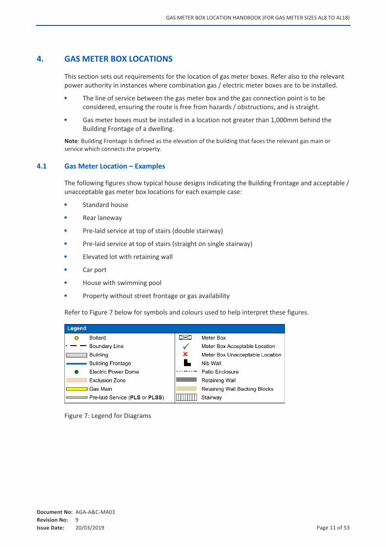
4.1 Gas Meter Location – Examples
The following figures show typical house designs indicating the Building Frontage and acceptable / unacceptable gas meter box locations for each example case:
Standard house
Rear laneway
Pre-laid service at top of stairs (double stairway)
Pre-laid service at top of stairs (straight on single stairway)
Elevated lot with retaining wall
Car port
House with swimming pool
Property without street frontage or gas availability
Refer to Figure 7 below for symbols and colours used to help interpret these figures.
Figure 7: Legend for Diagrams
GAS METER BOX LOCATION HANDBOOK (FOR GAS METER SIZES AL8 TO AL18)
Document No: AGA-A&C-MA03
Revision No: 9
Issue Date: 20/03/2019 Page 12 of 53
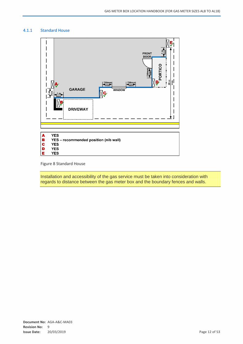
4.1.1 Standard House
Figure 8 Standard House
Installation and accessibility of the gas service must be taken into consideration with regards to distance between the gas meter box and the boundary fences and walls.
GAS METER BOX LOCATION HANDBOOK (FOR GAS METER SIZES AL8 TO AL18)
Document No: AGA-A&C-MA03
Revision No: 9
Issue Date: 20/03/2019 Page 13 of 53
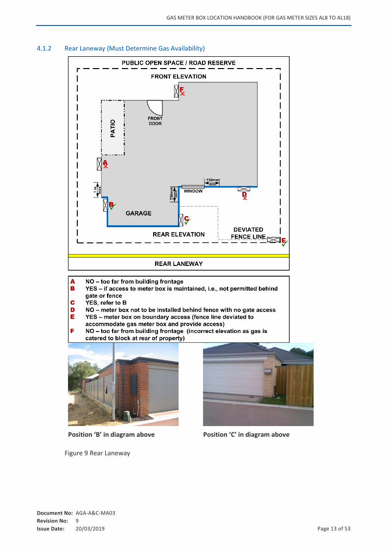
4.1.2 Rear Laneway (Must Determine Gas Availability)
Position ‘B’ in diagram above Position ‘C’ in diagram above
Figure 9 Rear Laneway
GAS METER BOX LOCATION HANDBOOK (FOR GAS METER SIZES AL8 TO AL18)
Document No: AGA-A&C-MA03
Revision No: 9
Issue Date: 20/03/2019 Page 14 of 53
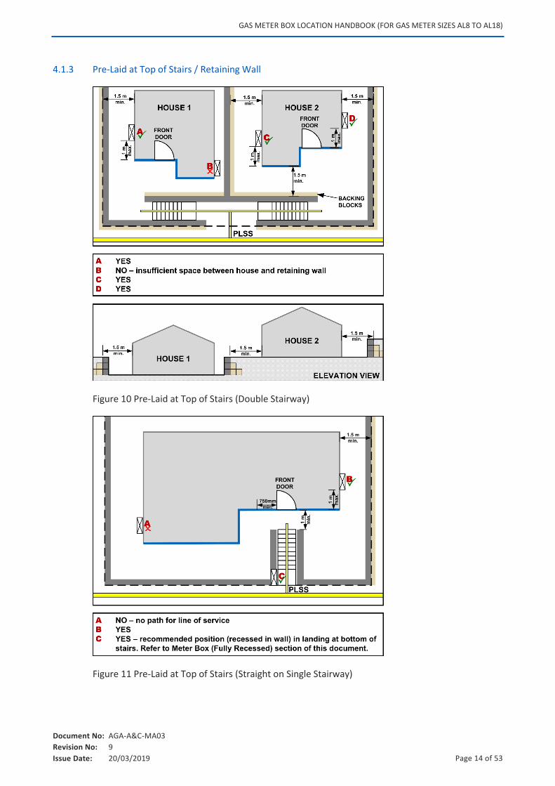
4.1.3 Pre-Laid at Top of Stairs / Retaining Wall
Figure 10 Pre-Laid at Top of Stairs (Double Stairway)
Figure 11 Pre-Laid at Top of Stairs (Straight on Single Stairway)
GAS METER BOX LOCATION HANDBOOK (FOR GAS METER SIZES AL8 TO AL18)
Document No: AGA-A&C-MA03
Revision No: 9
Issue Date: 20/03/2019 Page 15 of 53
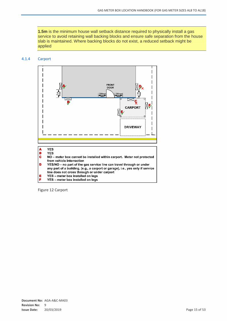
1.5m is the minimum house wall setback distance required to physically install a gas service to avoid retaining wall backing blocks and ensure safe separation from the house slab is maintained. Where backing blocks do not exist, a reduced setback might be applied
4.1.4 Carport
Figure 12 Carport
GAS METER BOX LOCATION HANDBOOK (FOR GAS METER SIZES AL8 TO AL18)
Document No: AGA-A&C-MA03
Revision No: 9
Issue Date: 20/03/2019 Page 16 of 53
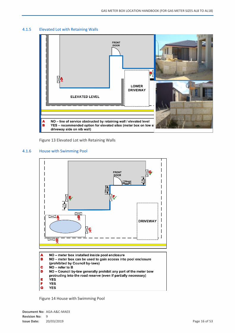
4.1.5 Elevated Lot with Retaining Walls
Figure 13 Elevated Lot with Retaining Walls
4.1.6 House with Swimming Pool
Figure 14 House with Swimming Pool
GAS METER BOX LOCATION HANDBOOK (FOR GAS METER SIZES AL8 TO AL18)
Document No: AGA-A&C-MA03
Revision No: 9
Issue Date: 20/03/2019 Page 17 of 53
Note: A gas service line must not travel through any part of a pool enclosure. Should any future works position the gas service inside the pool area, the Responsible Person must complete an Alter Gas Meter / Service Position – Request Form.
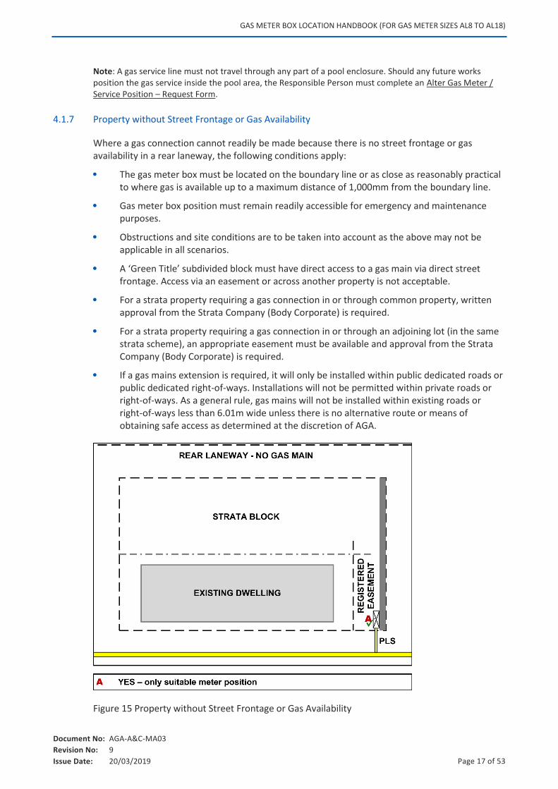
4.1.7 Property without Street Frontage or Gas Availability
Where a gas connection cannot readily be made because there is no street frontage or gas availability in a rear laneway, the following conditions apply:
The gas meter box must be located on the boundary line or as close as reasonably practical to where gas is available up to a maximum distance of 1,000mm from the boundary line.
Gas meter box position must remain readily accessible for emergency and maintenance purposes.
Obstructions and site conditions are to be taken into account as the above may not be applicable in all scenarios.
A ‘Green Title’ subdivided block must have direct access to a gas main via direct street frontage. Access via an easement or across another property is not acceptable.
For a strata property requiring a gas connection in or through common property, written approval from the Strata Company (Body Corporate) is required.
For a strata property requiring a gas connection in or through an adjoining lot (in the same strata scheme), an appropriate easement must be available and approval from the Strata Company (Body Corporate) is required.
If a gas mains extension is required, it will only be installed within public dedicated roads or public dedicated right-of-ways. Installations will not be permitted within private roads or right-of-ways. As a general rule, gas mains will not be installed within existing roads or right-of-ways less than 6.01m wide unless there is no alternative route or means of obtaining safe access as determined at the discretion of AGA.
Figure 15 Property without Street Frontage or Gas Availability
GAS METER BOX LOCATION HANDBOOK (FOR GAS METER SIZES AL8 TO AL18)
Document No: AGA-A&C-MA03
Revision No: 9
Issue Date: 20/03/2019 Page 18 of 53
AGA will not install a new gas service line which crosses through an adjoining lot in order to provide a service to a subdivided property. However in some circumstances AGA may, at its absolute discretion, determine that a new gas service line can be installed where it crosses another property.
Examples of factors that may be taken into consideration by AGA:
There is an existing gas service line or gas meter that requires relocation.
Written agreement has been obtained from all affected Responsible Persons in relation to the location of the service line.
In an existing strata scheme, written agreement has been obtained from all affected land owners in relation to the location of the gas service line.
Whether gas easements have been registered.
GAS METER BOX LOCATION HANDBOOK (FOR GAS METER SIZES AL8 TO AL18)
Document No: AGA-A&C-MA03
Revision No: 9
Issue Date: 20/03/2019 Page 19 of 53
4.2 Gas Meter Box Location Restrictions (AS/NZS 4645)
The gas meter shall not be installed in any of the following locations in accordance with AS/NZS 4645.1:2008 (Appendix K):
A bedroom.
A lift shaft or lift motor room.
A room specifically intended for electrical switchgear.
A fire-isolated stairway or passage.
A fire hydrant duct or hose reel cabinet.
Sprinkler or hydrant pump room.
Gas meter boxes must not be located closer than 500mm from a source of ignition. Sources of ignition include electrical devices such as the external unit of a split system air conditioner, pool pumps, external power points, etc.
Where egress from a building would be obstructed.
Where excessive temperatures or sudden excessive changes in temperature may occur.
In a cavity wall, unless installed in an approved ventilated enclosure which is sealed from the cavity.
Where access for reading or maintenance is restricted.
In an unventilated position.
On or in the ground.
On a floor which contains material which may corrode the gas meter.
Where subject to physical damage unless the gas meter is adequately protected. The definition of adequate protection shall be determined by AGA in all instances.
4.3 Other Location Restrictions
This section identifies other restrictions that must be considered when locating a gas meter box.
4.3.1 Service Regulator Installation Restrictions (AS/NZS 4645)
The gas service regulator shall not be installed in any of the following locations in accordance with AS/NZS 4645.1:2008 (Appendix J3):
i) A lift shaft.
ii) A lift motor room.
iii) A room specifically intended for electrical switch gear.
iv) A position that would obstruct egress from the building in the event of an emergency.
v) A bedroom.
vi) A fire-isolated stairway or passage.
vii) A fire hydrant duct or hose reel cabinet.
viii) Sprinkler or hydrant pump room.
GAS METER BOX LOCATION HANDBOOK (FOR GAS METER SIZES AL8 TO AL18)
Document No: AGA-A&C-MA03
Revision No: 9
Issue Date: 20/03/2019 Page 20 of 53
ix) Near a source of ignition.
x) In a position that would obstruct egress from a building.
xi) In the foundation area under a building.
xii) In a cavity wall, unless installed in an adequately ventilated enclosure and the cavity is sealed.
xiii) On the ground.
xiv) On a floor which is frequently wetted.
xv) On a floor which contains material which may corrode the service regulator.
A service regulator may be installed in an enclosure adjoining but not directly communicating with a location referred to in the last paragraph above, providing the walls, doors or access to such an enclosure are not within the path of egress from a fire exit. The walls and door of the enclosure shall have a fire resistance rating acceptable to the statutory authority responsible for building regulations.
The location of a service regulator shall provide ready and safe access for authorised persons carrying out maintenance.
4.3.2 Gas Meter Box Restrictions in Other Localities
A gas meter box must not be installed in the following locations:
On a fence, unless the fence is constructed of masonry.
Note: Local council by-laws prohibit fixing gas meter boxes to a neighbouring boundary fence.
On, or recessed into, limestone walls.
Note: This does not apply to reconstituted limestone walls.
In a carport or any other location where it may be struck by vehicular traffic.
In a situation where there is an obstruction to installing the gas service, maintaining or reading the gas meter or accessing the gas meter box in an emergency.
In a position where any part of the gas service to supply the gas meter box has to pass under any part of a building (i.e., carport, garage, etc.).
Where excavation alongside an unsupported wall or structure will compromise that wall or structure.
On the fence of, or within a pool or spa area.
Behind fencing or a locked gate, unless the lock is an approved WA Services (WAS) lock, and the gas meter remains readily accessible at all times.
In a position that contravenes the requirements of other utility service providers.
Ensure that the gas meter box is installed within the property boundary for the property requiring the gas connection, unless other arrangements have been accepted by AGA in writing.
4.4 Obstructions (When Gas Meter Boxes Cannot be installed on Dwellings)
There are circumstances that require a gas meter box to be placed at a location other than on the dwelling (e.g., on the property boundary).
GAS METER BOX LOCATION HANDBOOK (FOR GAS METER SIZES AL8 TO AL18)
Document No: AGA-A&C-MA03
Revision No: 9
Issue Date: 20/03/2019 Page 21 of 53
In these instances, to avoid delays contact AGA on 13 13 56.
The following are examples of obstructions necessitating an alternative installation location:
Steep site levels
Soil conditions that may include limestone or rock
Tiered or terraced gardens
Trees or dense vegetation
Retaining walls
On or above elevated ground
Gas meter boxes must remain readily accessible
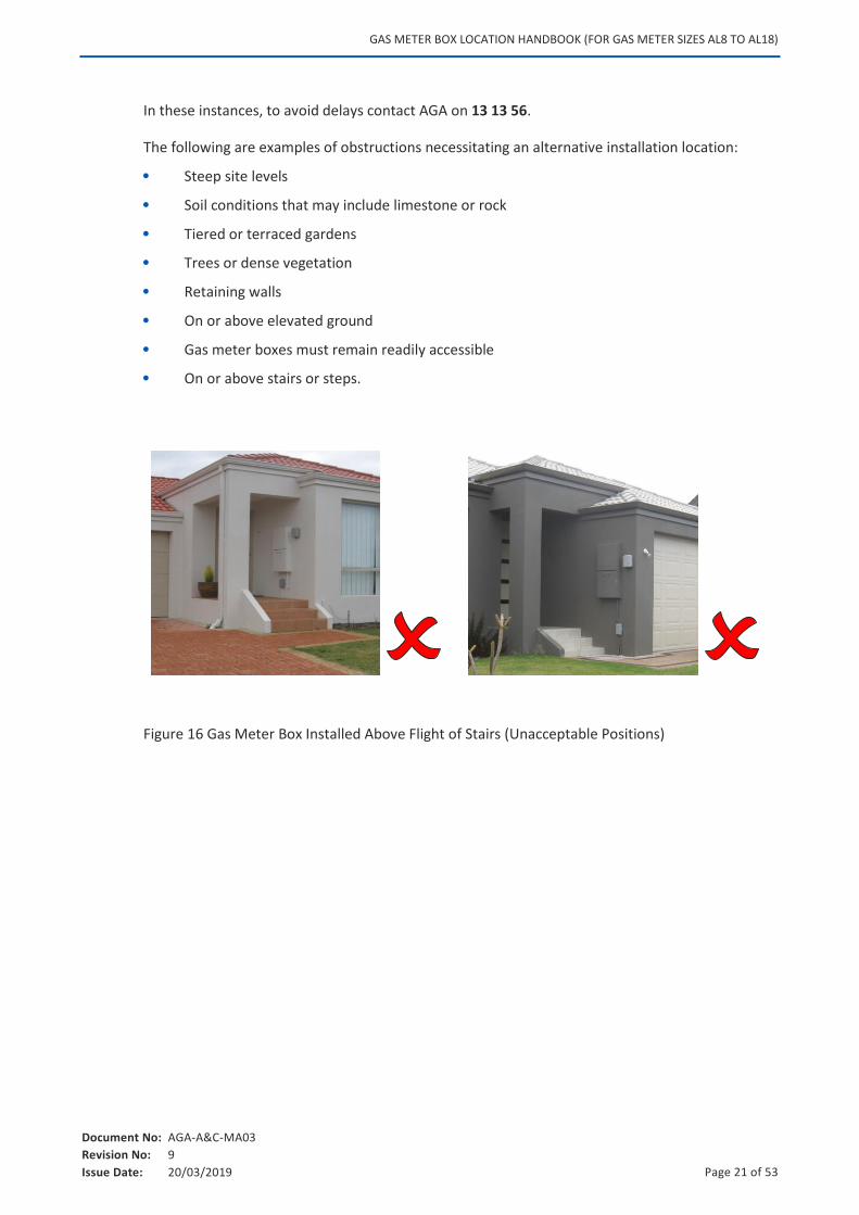
On or above stairs or steps.
Figure 16 Gas Meter Box Installed Above Flight of Stairs (Unacceptable Positions)
GAS METER BOX LOCATION HANDBOOK (FOR GAS METER SIZES AL8 TO AL18)
Document No: AGA-A&C-MA03
Revision No: 9
Issue Date: 20/03/2019 Page 22 of 53
5. GAS METER BOX INSTALLATION REQUIREMENTS
This section provides general information for gas meter boxes which must meet all ATCO Gas Australia design (dimension, ventilation, security, material) and mounting requirements.
Specific gas meter box dimensions can be provided by AGA upon request.
5.1 Requirements
A gas meter box may be surface mounted or semi-recessed and must satisfy the location requirements set out below.
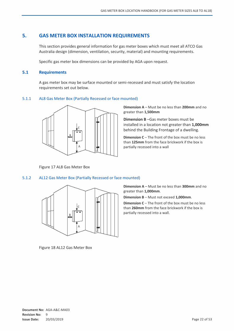
5.1.1 AL8 Gas Meter Box (Partially Recessed or face mounted)
Dimension A – Must be no less than 200mm and no greater than 1,500mm
Dimension B –Gas meter boxes must be installed in a location not greater than 1,000mm behind the Building Frontage of a dwelling.
Dimension C – The front of the box must be no less than 125mm from the face brickwork if the box is partially recessed into a wall
Figure 17 AL8 Gas Meter Box
5.1.2 AL12 Gas Meter Box (Partially Recessed or face mounted)
Dimension A – Must be no less than 300mm and no greater than 1,000mm.
Dimension B – Must not exceed 1,000mm.
Dimension C – The front of the box must be no less than 260mm from the face brickwork if the box is partially recessed into a wall.
Figure 18 AL12 Gas Meter Box
GAS METER BOX LOCATION HANDBOOK (FOR GAS METER SIZES AL8 TO AL18)
Document No: AGA-A&C-MA03
Revision No: 9
Issue Date: 20/03/2019 Page 23 of 53
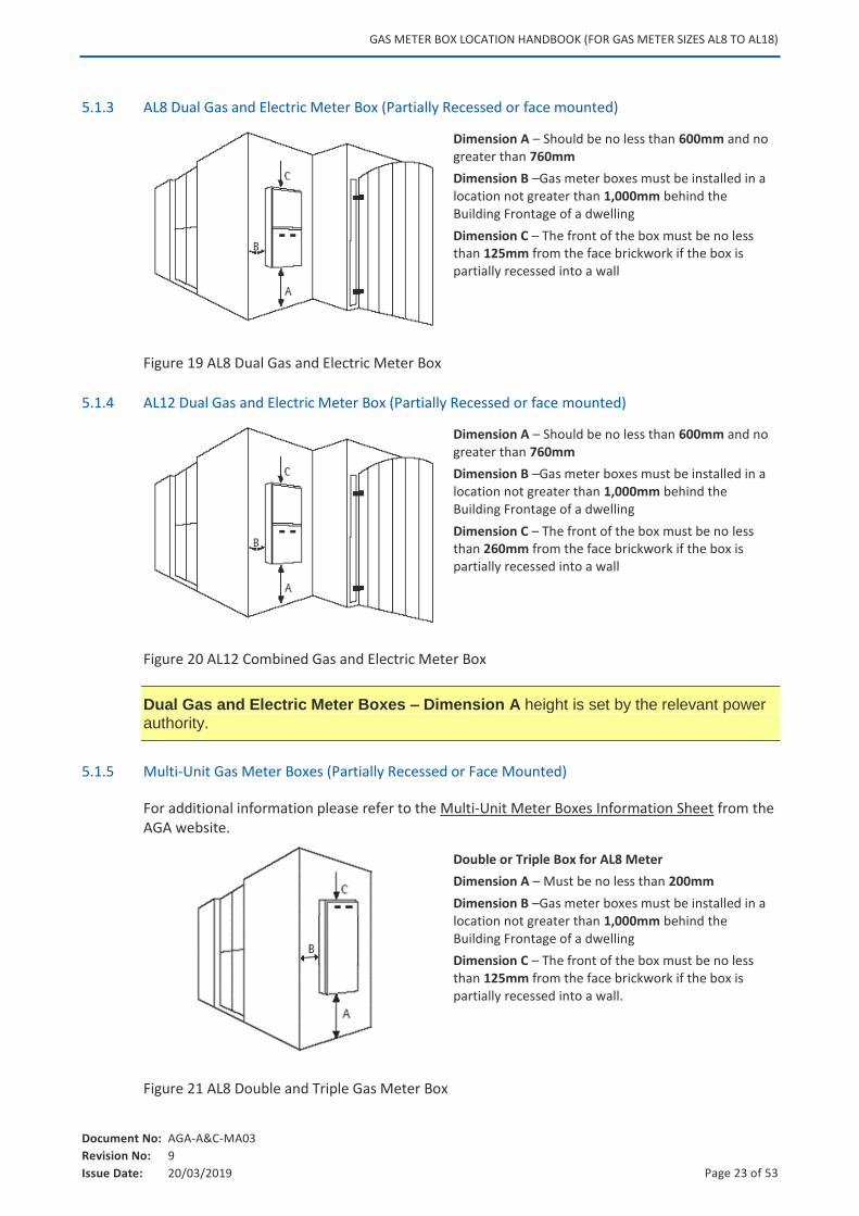
5.1.3 AL8 Dual Gas and Electric Meter Box (Partially Recessed or face mounted)
Dimension A – Should be no less than 600mm and no greater than 760mm
Dimension B –Gas meter boxes must be installed in a location not greater than 1,000mm behind the Building Frontage of a dwelling
Dimension C – The front of the box must be no less than 125mm from the face brickwork if the box is partially recessed into a wall
Figure 19 AL8 Dual Gas and Electric Meter Box
5.1.4 AL12 Dual Gas and Electric Meter Box (Partially Recessed or face mounted)
Dimension A – Should be no less than 600mm and no greater than 760mm
Dimension B –Gas meter boxes must be installed in a location not greater than 1,000mm behind the Building Frontage of a dwelling
Dimension C – The front of the box must be no less than 260mm from the face brickwork if the box is partially recessed into a wall
Figure 20 AL12 Combined Gas and Electric Meter Box
Dual Gas and Electric Meter Boxes – Dimension A height is set by the relevant power authority.
5.1.5 Multi-Unit Gas Meter Boxes (Partially Recessed or Face Mounted)
For additional information please refer to the Multi-Unit Meter Boxes Information Sheet from the AGA website.
Double or Triple Box for AL8 Meter
Dimension A – Must be no less than 200mm
Dimension B –Gas meter boxes must be installed in a location not greater than 1,000mm behind the Building Frontage of a dwelling
Dimension C – The front of the box must be no less than 125mm from the face brickwork if the box is partially recessed into a wall.
Figure 21 AL8 Double and Triple Gas Meter Box
GAS METER BOX LOCATION HANDBOOK (FOR GAS METER SIZES AL8 TO AL18)
Document No: AGA-A&C-MA03
Revision No: 9
Issue Date: 20/03/2019 Page 24 of 53
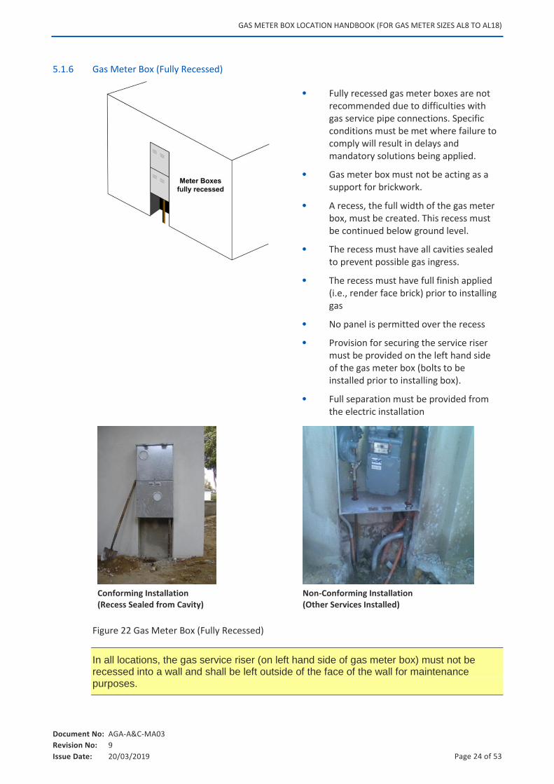
5.1.6 Gas Meter Box (Fully Recessed)
Fully recessed gas meter boxes are not recommended due to difficulties with gas service pipe connections. Specific conditions must be met where failure to comply will result in delays and mandatory solutions being applied.
Gas meter box must not be acting as a support for brickwork.
A recess, the full width of the gas meter box, must be created. This recess must be continued below ground level.
The recess must have all cavities sealed to prevent possible gas ingress.
The recess must have full finish applied (i.e., render face brick) prior to installing gas
No panel is permitted over the recess
Provision for securing the service riser must be provided on the left hand side of the gas meter box (bolts to be installed prior to installing box).
Full separation must be provided from the electric installation
Conforming Installation (Recess Sealed from Cavity)
Non-Conforming Installation (Other Services Installed)
Figure 22 Gas Meter Box (Fully Recessed)
In all locations, the gas service riser (on left hand side of gas meter box) must not be recessed into a wall and shall be left outside of the face of the wall for maintenance purposes.
GAS METER BOX LOCATION HANDBOOK (FOR GAS METER SIZES AL8 TO AL18)
Document No: AGA-A&C-MA03
Revision No: 9
Issue Date: 20/03/2019 Page 25 of 53
5.2 Gas Meter Box Mounted on Walls
A gas meter box may be fixed to an exterior wall which is:
Constructed of masonry
Clad, provided it is suitably fixed to framework underneath the cladding
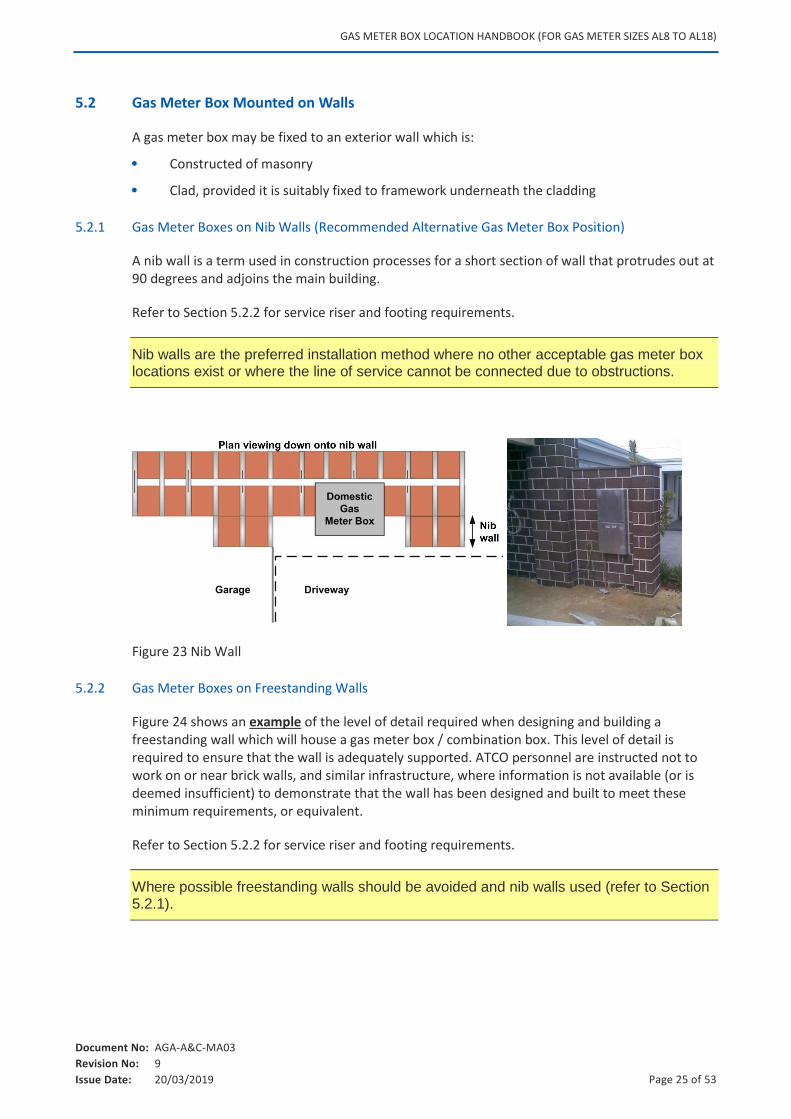
5.2.1 Gas Meter Boxes on Nib Walls (Recommended Alternative Gas Meter Box Position)
A nib wall is a term used in construction processes for a short section of wall that protrudes out at 90 degrees and adjoins the main building.
Refer to Section 5.2.2 for service riser and footing requirements.
Nib walls are the preferred installation method where no other acceptable gas meter box locations exist or where the line of service cannot be connected due to obstructions.
Figure 23 Nib Wall
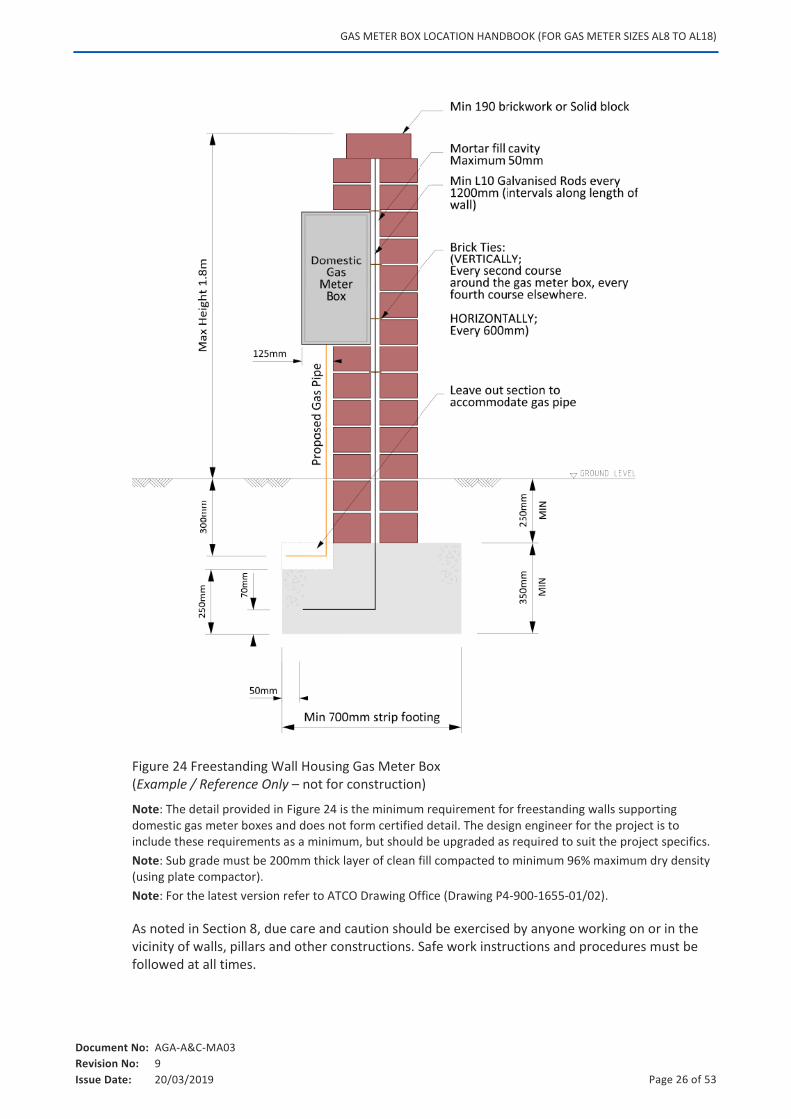
5.2.2 Gas Meter Boxes on Freestanding Walls
Figure 24 shows an example of the level of detail required when designing and building a freestanding wall which will house a gas meter box / combination box. This level of detail is required to ensure that the wall is adequately supported. ATCO personnel are instructed not to work on or near brick walls, and similar infrastructure, where information is not available (or is deemed insufficient) to demonstrate that the wall has been designed and built to meet these minimum requirements, or equivalent.
Refer to Section 5.2.2 for service riser and footing requirements.
Where possible freestanding walls should be avoided and nib walls used (refer to Section 5.2.1).
GAS METER BOX LOCATION HANDBOOK (FOR GAS METER SIZES AL8 TO AL18)
Document No: AGA-A&C-MA03
Revision No: 9
Issue Date: 20/03/2019 Page 26 of 53
Figure 24 Freestanding Wall Housing Gas Meter Box (Example / Reference Only – not for construction)
Note: The detail provided in Figure 24 is the minimum requirement for freestanding walls supporting domestic gas meter boxes and does not form certified detail. The design engineer for the project is to include these requirements as a minimum, but should be upgraded as required to suit the project specifics.
Note: Sub grade must be 200mm thick layer of clean fill compacted to minimum 96% maximum dry density (using plate compactor).
Note: For the latest version refer to ATCO Drawing Office (Drawing P4-900-1655-01/02).
As noted in Section 8, due care and caution should be exercised by anyone working on or in the vicinity of walls, pillars and other constructions. Safe work instructions and procedures must be followed at all times.
GAS METER BOX LOCATION HANDBOOK (FOR GAS METER SIZES AL8 TO AL18)
Document No: AGA-A&C-MA03
Revision No: 9
Issue Date: 20/03/2019 Page 27 of 53
You should conduct your own independent due-diligence checks and verifications, such as obtaining advice from relevant competent engineering experts, and other relevant professionals. This includes ensuring the stability, structural integrity, support, durability, performance, drainage, safety, quality, adequacy, fitness for purpose, and compliance with all relevant laws, standards and codes of such constructions.
These checks apply to all constructions, including: any wall / pillar location, footings, foundations, protections, materials and any equipment, fittings, wires, cabling, pipes, conduits or apparatus (including any gas meter box) to be used, applied or installed in relation to the construction. These checks shall also be applied (as relevant) to the full lifecycle of activities, including maintenance, upkeep, repair, monitoring and checking of any such constructions on an ongoing basis.
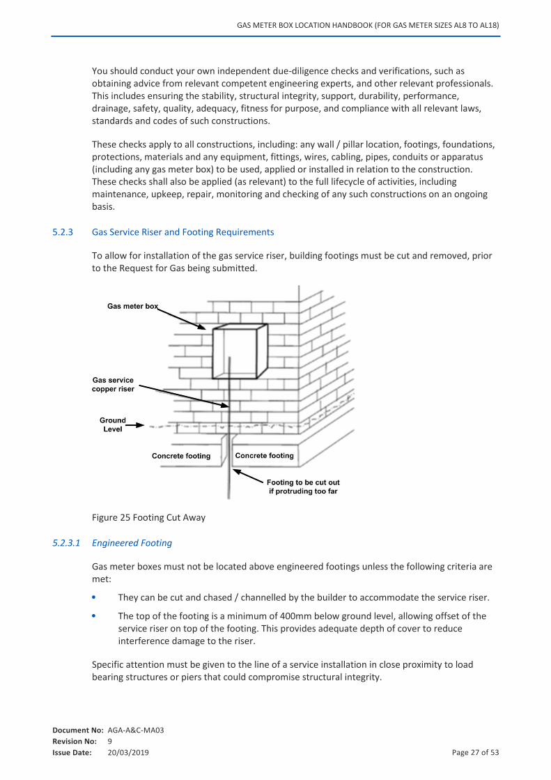
5.2.3 Gas Service Riser and Footing Requirements
To allow for installation of the gas service riser, building footings must be cut and removed, prior to the Request for Gas being submitted.
Figure 25 Footing Cut Away
5.2.3.1 Engineered Footing
Gas meter boxes must not be located above engineered footings unless the following criteria are met:
They can be cut and chased / channelled by the builder to accommodate the service riser.
The top of the footing is a minimum of 400mm below ground level, allowing offset of the service riser on top of the footing. This provides adequate depth of cover to reduce interference damage to the riser.
Specific attention must be given to the line of a service installation in close proximity to load bearing structures or piers that could compromise structural integrity.
GAS METER BOX LOCATION HANDBOOK (FOR GAS METER SIZES AL8 TO AL18)
Document No: AGA-A&C-MA03
Revision No: 9
Issue Date: 20/03/2019 Page 28 of 53
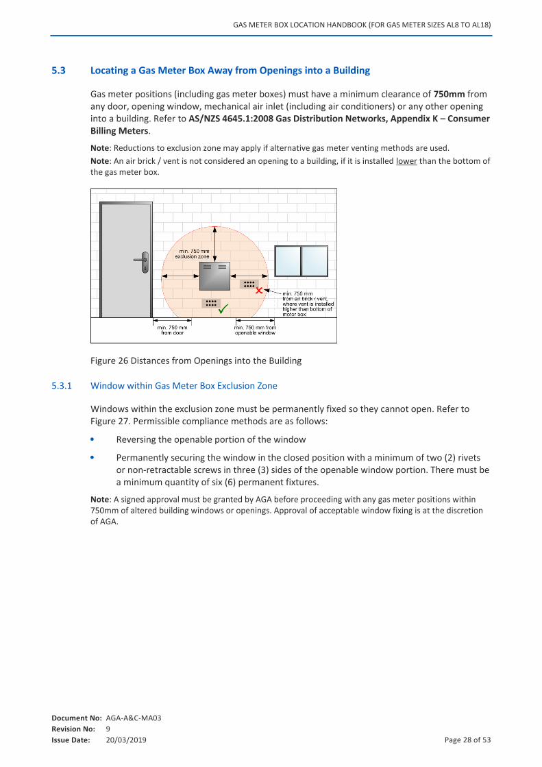
5.3 Locating a Gas Meter Box Away from Openings into a Building
Gas meter positions (including gas meter boxes) must have a minimum clearance of 750mm from any door, opening window, mechanical air inlet (including air conditioners) or any other opening into a building. Refer to AS/NZS 4645.1:2008 Gas Distribution Networks, Appendix K – Consumer Billing Meters.
Note: Reductions to exclusion zone may apply if alternative gas meter venting methods are used.
Note: An air brick / vent is not considered an opening to a building, if it is installed lower than the bottom of the gas meter box.
Figure 26 Distances from Openings into the Building
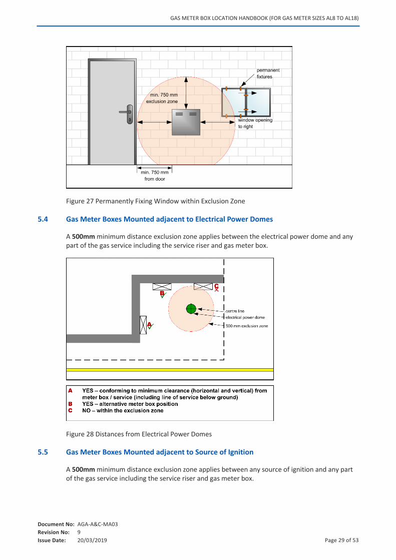
5.3.1 Window within Gas Meter Box Exclusion Zone
Windows within the exclusion zone must be permanently fixed so they cannot open. Refer to Figure 27. Permissible compliance methods are as follows:
Reversing the openable portion of the window
Permanently securing the window in the closed position with a minimum of two (2) rivets or non-retractable screws in three (3) sides of the openable window portion. There must be a minimum quantity of six (6) permanent fixtures.
Note: A signed approval must be granted by AGA before proceeding with any gas meter positions within 750mm of altered building windows or openings. Approval of acceptable window fixing is at the discretion of AGA.
GAS METER BOX LOCATION HANDBOOK (FOR GAS METER SIZES AL8 TO AL18)
Document No: AGA-A&C-MA03
Revision No: 9
Issue Date: 20/03/2019 Page 29 of 53
Figure 27 Permanently Fixing Window within Exclusion Zone
5.4 Gas Meter Boxes Mounted adjacent to Electrical Power Domes
A 500mm minimum distance exclusion zone applies between the electrical power dome and any part of the gas service including the service riser and gas meter box.
Figure 28 Distances from Electrical Power Domes
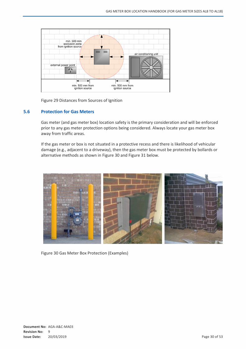
5.5 Gas Meter Boxes Mounted adjacent to Source of Ignition
A 500mm minimum distance exclusion zone applies between any source of ignition and any part of the gas service including the service riser and gas meter box.
GAS METER BOX LOCATION HANDBOOK (FOR GAS METER SIZES AL8 TO AL18)
Document No: AGA-A&C-MA03
Revision No: 9
Issue Date: 20/03/2019 Page 30 of 53
Figure 29 Distances from Sources of Ignition
5.6 Protection for Gas Meters
Gas meter (and gas meter box) location safety is the primary consideration and will be enforced prior to any gas meter protection options being considered. Always locate your gas meter box away from traffic areas.
If the gas meter or box is not situated in a protective recess and there is likelihood of vehicular damage (e.g., adjacent to a driveway), then the gas meter box must be protected by bollards or alternative methods as shown in Figure 30 and Figure 31 below.
Figure 30 Gas Meter Box Protection (Examples)
GAS METER BOX LOCATION HANDBOOK (FOR GAS METER SIZES AL8 TO AL18)
Document No: AGA-A&C-MA03
Revision No: 9
Issue Date: 20/03/2019 Page 31 of 53
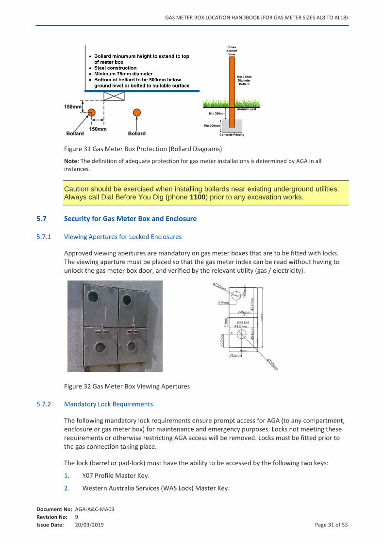
Figure 31 Gas Meter Box Protection (Bollard Diagrams)
Note: The definition of adequate protection for gas meter installations is determined by AGA in all instances.
Caution should be exercised when installing bollards near existing underground utilities. Always call Dial Before You Dig (phone 1100) prior to any excavation works.
5.7 Security for Gas Meter Box and Enclosure
5.7.1 Viewing Apertures for Locked Enclosures
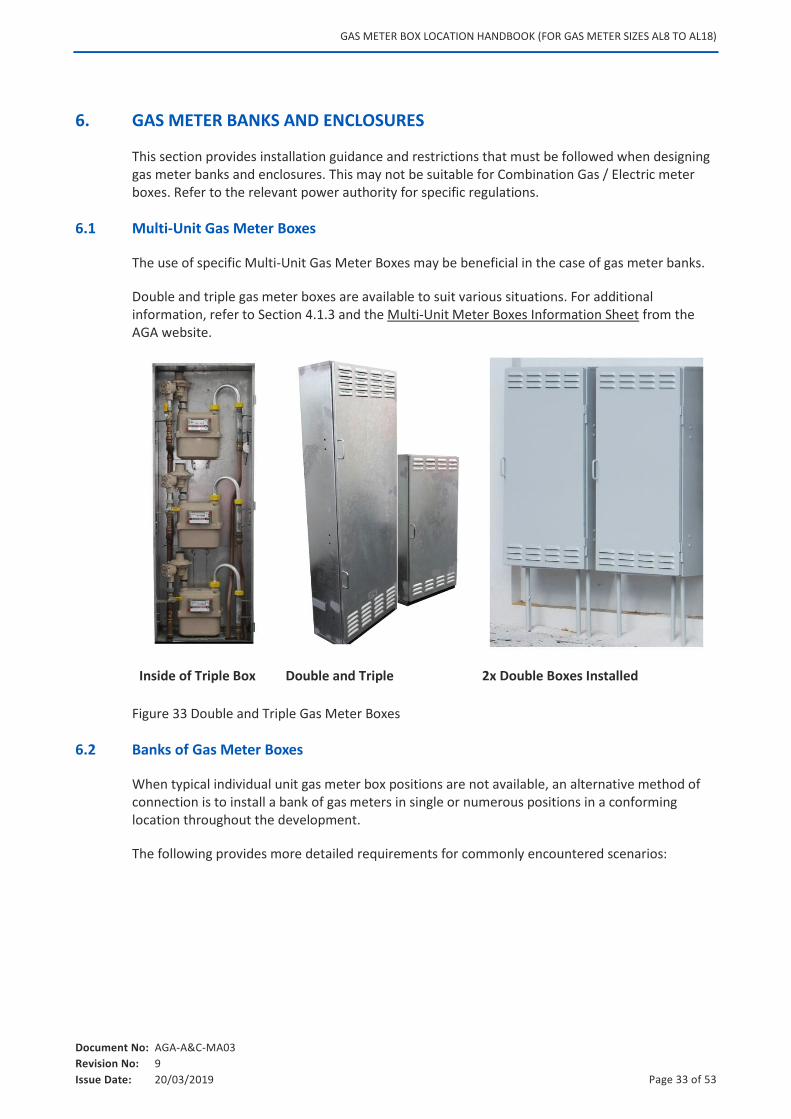
Approved viewing apertures are mandatory on gas meter boxes that are to be fitted with locks. The viewing aperture must be placed so that the gas meter index can be read without having to unlock the gas meter box door, and verified by the relevant utility (gas / electricity).
Figure 32 Gas Meter Box Viewing Apertures
5.7.2 Mandatory Lock Requirements
The following mandatory lock requirements ensure prompt access for AGA (to any compartment, enclosure or gas meter box) for maintenance and emergency purposes. Locks not meeting these requirements or otherwise restricting AGA access will be removed. Locks must be fitted prior to the gas connection taking place.
The lock (barrel or pad-lock) must have the ability to be accessed by the following two keys:
1. Y07 Profile Master Key.
2. Western Australia Services (WAS Lock) Master Key.

GAS METER BOX LOCATION HANDBOOK (FOR GAS METER SIZES AL8 TO AL18)
Document No: AGA-A&C-MA03
Revision No: 9
Issue Date: 20/03/2019 Page 32 of 53
Note: Refer to the relevant power authority for locking details of electrical meter boxes.
GAS METER BOX LOCATION HANDBOOK (FOR GAS METER SIZES AL8 TO AL18)
Document No: AGA-A&C-MA03
Revision No: 9
Issue Date: 20/03/2019 Page 33 of 53
6. GAS METER BANKS AND ENCLOSURES
This section provides installation guidance and restrictions that must be followed when designing gas meter banks and enclosures. This may not be suitable for Combination Gas / Electric meter boxes. Refer to the relevant power authority for specific regulations.
6.1 Multi-Unit Gas Meter Boxes
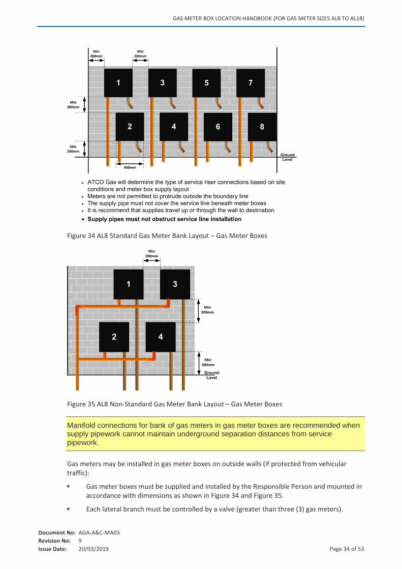
The use of specific Multi-Unit Gas Meter Boxes may be beneficial in the case of gas meter banks.
Double and triple gas meter boxes are available to suit various situations. For additional information, refer to Section 4.1.3 and the Multi-Unit Meter Boxes Information Sheet from the AGA website.
Inside of Triple Box Double and Triple 2x Double Boxes Installed
Figure 33 Double and Triple Gas Meter Boxes
6.2 Banks of Gas Meter Boxes
When typical individual unit gas meter box positions are not available, an alternative method of connection is to install a bank of gas meters in single or numerous positions in a conforming location throughout the development.
The following provides more detailed requirements for commonly encountered scenarios:
GAS METER BOX LOCATION HANDBOOK (FOR GAS METER SIZES AL8 TO AL18)
Document No: AGA-A&C-MA03
Revision No: 9
Issue Date: 20/03/2019 Page 34 of 53
Figure 34 AL8 Standard Gas Meter Bank Layout – Gas Meter Boxes
Figure 35 AL8 Non-Standard Gas Meter Bank Layout – Gas Meter Boxes
Manifold connections for bank of gas meters in gas meter boxes are recommended when supply pipework cannot maintain underground separation distances from service pipework.
Gas meters may be installed in gas meter boxes on outside walls (if protected from vehicular traffic):
Gas meter boxes must be supplied and installed by the Responsible Person and mounted in accordance with dimensions as shown in Figure 34 and Figure 35.
Each lateral branch must be controlled by a valve (greater than three (3) gas meters).
GAS METER BOX LOCATION HANDBOOK (FOR GAS METER SIZES AL8 TO AL18)
Document No: AGA-A&C-MA03
Revision No: 9
Issue Date: 20/03/2019 Page 35 of 53
In all gas meter bank and enclosures, unit numbers are to be indicated in or on each gas meter box or bracket prior to the gas connection taking place.
6.3 Banks of Gas Meters Mounted on AGA Approved Brackets in Building Recesses
Enclosure width is to be determined from the number of gas meters to be situated in the enclosure.
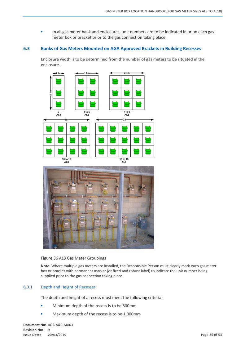
Figure 36 AL8 Gas Meter Groupings
Note: Where multiple gas meters are installed, the Responsible Person must clearly mark each gas meter box or bracket with permanent marker (or fixed and robust label) to indicate the unit number being supplied prior to the gas connection taking place.
6.3.1 Depth and Height of Recesses
The depth and height of a recess must meet the following criteria:
Minimum depth of the recess is to be 600mm
Maximum depth of the recess is to be 1,000mm
GAS METER BOX LOCATION HANDBOOK (FOR GAS METER SIZES AL8 TO AL18)
Document No: AGA-A&C-MA03
Revision No: 9
Issue Date: 20/03/2019 Page 36 of 53
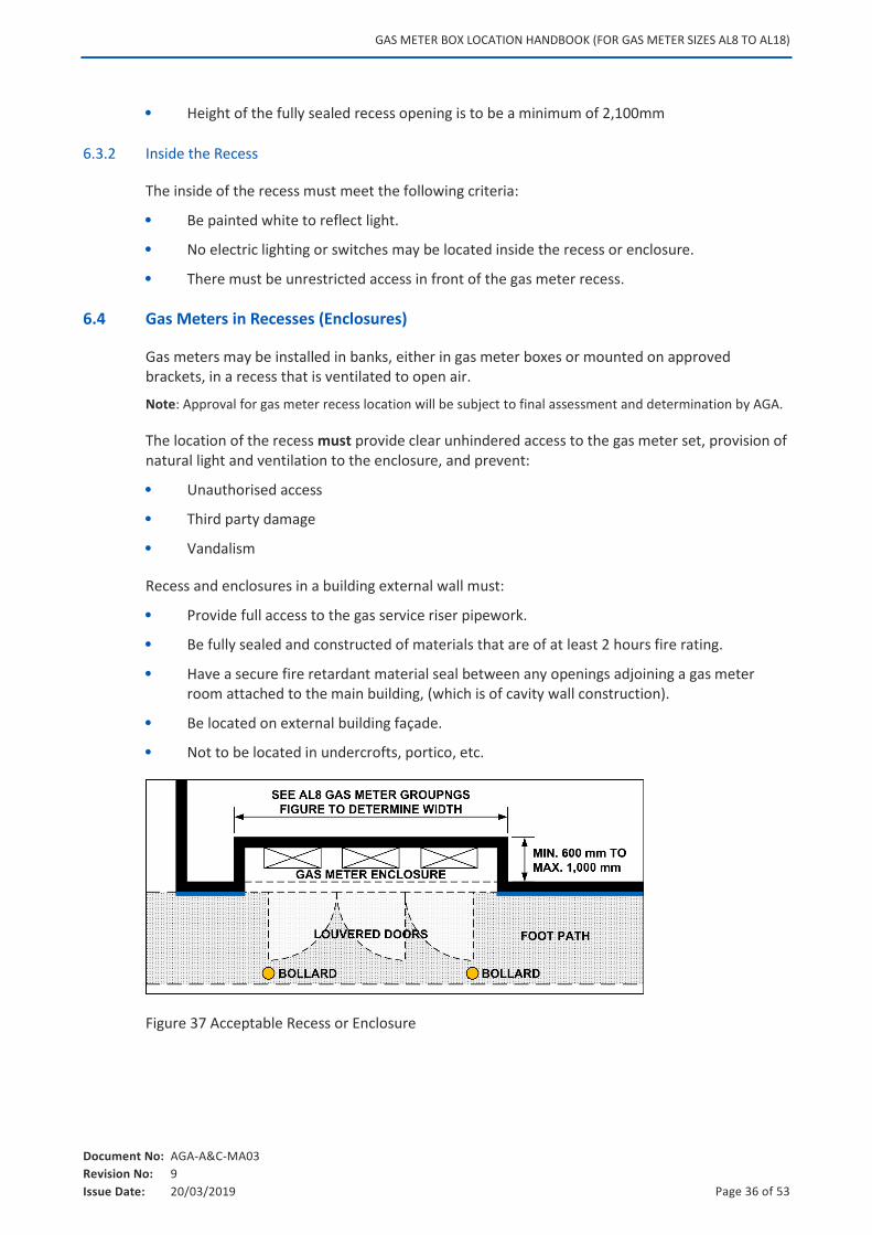
Height of the fully sealed recess opening is to be a minimum of 2,100mm
6.3.2 Inside the Recess
The inside of the recess must meet the following criteria:
Be painted white to reflect light.
No electric lighting or switches may be located inside the recess or enclosure.
There must be unrestricted access in front of the gas meter recess.
6.4 Gas Meters in Recesses (Enclosures)
Gas meters may be installed in banks, either in gas meter boxes or mounted on approved brackets, in a recess that is ventilated to open air.
Note: Approval for gas meter recess location will be subject to final assessment and determination by AGA.
The location of the recess must provide clear unhindered access to the gas meter set, provision of natural light and ventilation to the enclosure, and prevent:
Unauthorised access
Third party damage
Vandalism
Recess and enclosures in a building external wall must:
Provide full access to the gas service riser pipework.
Be fully sealed and constructed of materials that are of at least 2 hours fire rating.
Have a secure fire retardant material seal between any openings adjoining a gas meter room attached to the main building, (which is of cavity wall construction).
Be located on external building façade.
Not to be located in undercrofts, portico, etc.
Figure 37 Acceptable Recess or Enclosure
GAS METER BOX LOCATION HANDBOOK (FOR GAS METER SIZES AL8 TO AL18)
Document No: AGA-A&C-MA03
Revision No: 9
Issue Date: 20/03/2019 Page 37 of 53
Note: There must be one (1) metre of unrestricted space in front of gas meter recess and the edge of the recess must be 750mm away from an opening into a building.
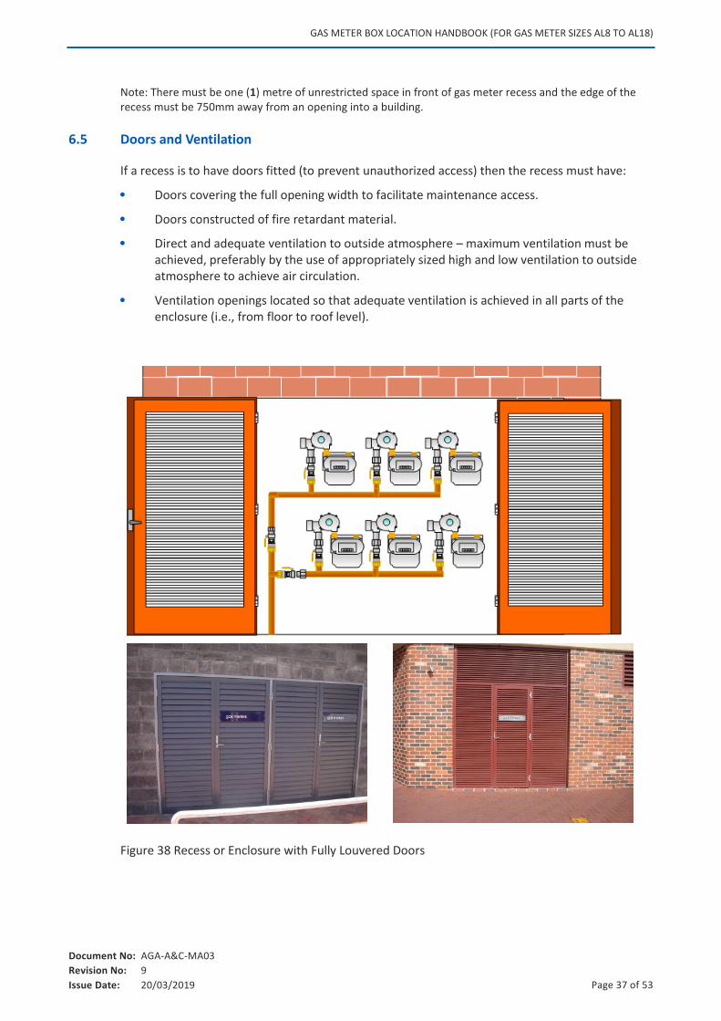
6.5 Doors and Ventilation
If a recess is to have doors fitted (to prevent unauthorized access) then the recess must have:
Doors covering the full opening width to facilitate maintenance access.
Doors constructed of fire retardant material.
Direct and adequate ventilation to outside atmosphere – maximum ventilation must be achieved, preferably by the use of appropriately sized high and low ventilation to outside atmosphere to achieve air circulation.
Ventilation openings located so that adequate ventilation is achieved in all parts of the enclosure (i.e., from floor to roof level).
Figure 38 Recess or Enclosure with Fully Louvered Doors
GAS METER BOX LOCATION HANDBOOK (FOR GAS METER SIZES AL8 TO AL18)
Document No: AGA-A&C-MA03
Revision No: 9
Issue Date: 20/03/2019 Page 38 of 53
6.6 Floor Finishes
Floor finishes shall be of 15mm blue metal (minimum 100mm thick) over plastic sheeting, except where the gas meter set is located in a position where the floor of the recess is part of the building. In this case, the gas meter riser shall be installed in a manner that will provide future access to the gas service riser pipework both above and below ground.
6.7 Security Access
All gas meter enclosures must have approved Western Australian Services (WAS) locks installed for maintenance and emergency access. For more information refer to Section 5.7.2 Mandatory Lock Requirements.
6.8 Signage
Recesses enclosed with doors must have appropriate signage on the outside to indicate gas meters are located inside.
GAS METER BOX LOCATION HANDBOOK (FOR GAS METER SIZES AL8 TO AL18)
Document No: AGA-A&C-MA03
Revision No: 9
Issue Date: 20/03/2019 Page 39 of 53
7. RELATED DOCUMENTS
The following AGA documentation must be referred to when positioning gas meter boxes:
AGA Documents Referenced
ATCO Gas Australia Policies, Procedures and SWIs (available upon request)
Connection Process Handbook
Multi-Unit Meter Box Information Sheet
Residential Unit Development Handbook
The following standards and legislation must also be referred to when positioning gas meter boxes:
Standards and Legislation
AS/NZS 4645.1 Gas Distribution Networks, Part 1 – Network Management
AS/NZS 4645.1 Gas Distribution Networks, Appendix K – Consumer Billing Meters
AS/NZS 4130 Polyethylene (PE) Pipes for Pressure Applications
AS/NZS 5601.1 Gas Installations
Energy Coordination Act 1994
Environmental Protection Act 1986
Gas Standard Act 1972
Gas Standards [Gas Fitting and Consumer Gas Installations] Regulations 1999
Occupational Safety and Health Act 1984
Occupational Safety and Health Regulations 1996
Utility Providers Code of Practice for Western Australia
Western Australia Excavation Code of Practice 2005
GAS METER BOX LOCATION HANDBOOK (FOR GAS METER SIZES AL8 TO AL18)
Document No: AGA-A&C-MA03
Revision No: 9
Issue Date: 20/03/2019 Page 40 of 53
8. DISCLAIMER
1. The diagrams provided in this document are not intended to be used as advice of any kind or a design for any construction or other purpose and must not be used or relied upon as such.
2. Information provided in this document relates only to installation of ATCO Gas Australia’s infrastructure and does not relate to installation of other utility services.
3. The diagrams and drawings provided are not to scale.
4. Diagrams provided in this document cannot be used to ensure the stability, structural integrity, support, durability, performance, drainage, safety, quality, adequacy, fitness for purpose or compliance with any law, standard or code of any wall, pillar or other construction or its location, footings, foundations, protections, materials or any equipment, fittings, wires, cabling, pipes, conduits or apparatus (including any gas meter box) used, applied or installed in relation to any construction.
5. Due care and caution should be exercised by anyone working on or near walls, pillars and other constructions. Safe work instructions and procedures should be followed at all times.
6. To the maximum extent allowed by law, no warranty or representation is given or made concerning the diagrams provided in this document (including as to quality, completeness, accuracy or fitness for any purpose or that it complies with any applicable laws, standards or codes).
7. You should conduct your own independent due diligence checks and verifications and obtain your own independent design and advice from relevant competent engineering experts and other professionals (including to ensure the stability, structural integrity, support, durability, performance, drainage, safety, quality, adequacy, fitness for any purpose and compliance with all relevant laws, standards and codes) for your own constructions (including for any wall or pillar), their location, footings, foundations, protections, materials and any equipment, fittings, wires, cabling, pipes, conduits or apparatus (including any gas meter box) to be used, applied or installed in relation to those constructions; and for the maintenance, upkeep, repair, monitoring and checking on an ongoing basis of any such constructions.
8. To the maximum extent allowed by law, ATCO Gas Australia, its related bodies corporate and officers, employees, agents or contractors are not liable in any way whatsoever (including for negligence, recklessness or breach of any statutory duty) for any loss, liability, cost or claim of any kind whatsoever (including any direct loss, indirect loss, consequential loss, economic loss, loss of profit, loss of opportunity, death, illness, injury or damage to reputation or goodwill) arising from or in relation to the use of or reliance on diagrams in this document.
9. ATCO Gas Australia reserves the right at any time (without giving any notice) modify, supplement or withdraw diagrams or any other part of this document.
10. In this document, ‘including’ means ‘including, but not limited to’. Reference to ‘this diagram’ includes any part of it (including any information or drawing in it).
11. ATCO Gas Australia owns the copyright in the diagram referred to as Figure 24 and does not give any license to copy or reproduce this diagram.
GAS METER BOX LOCATION HANDBOOK (FOR GAS METER SIZES AL8 TO AL18)
Document No: AGA-A&C-MA03
Revision No: 9
Issue Date: 20/03/2019 Page 41 of 53
9. APPENDICES
The Appendices contains printable forms, checklists and other information referred to throughout this document.
List of Appendices
Appendix A Gas Connection Checklist
Appendix B Gas Service Installation on Hold Form
Appendix C Gas Safety – DOs and DON’Ts
Appendix D Feedback Form

GAS METER BOX LOCATION HANDBOOK (FOR GAS METER SIZES AL8 TO AL18)
Document No: AGA-A&C-MA03
Revision No: 9
Issue Date: 20/03/2019 Page 42 of 53
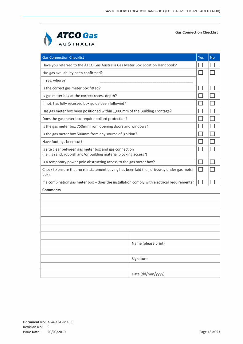
APPENDIX A. GAS CONNECTION CHECKLIST
GAS METER BOX LOCATION HANDBOOK (FOR GAS METER SIZES AL8 TO AL18)
Document No: AGA-A&C-MA03
Revision No: 9
Issue Date: 20/03/2019 Page 43 of 53
Gas Connection Checklist
Gas Connection Checklist Yes No
Have you referred to the ATCO Gas Australia Gas Meter Box Location Handbook?
Has gas availability been confirmed?
If Yes, where? ______________________________________________
Is the correct gas meter box fitted?
Is gas meter box at the correct recess depth?
If not, has fully recessed box guide been followed?
Has gas meter box been positioned within 1,000mm of the Building Frontage?
Does the gas meter box require bollard protection?
Is the gas meter box 750mm from opening doors and windows?
Is the gas meter box 500mm from any source of ignition?
Have footings been cut?
Is site clear between gas meter box and gas connection (i.e., is sand, rubbish and/or building material blocking access?)
Is a temporary power pole obstructing access to the gas meter box?
Check to ensure that no reinstatement paving has been laid (i.e., driveway under gas meter box).
If a combination gas meter box – does the installation comply with electrical requirements?
Comments
Name (please print)
Signature
Date (dd/mm/yyyy)

GAS METER BOX LOCATION HANDBOOK (FOR GAS METER SIZES AL8 TO AL18)
Document No: AGA-A&C-MA03
Revision No: 9
Issue Date: 20/03/2019 Page 44 of 53
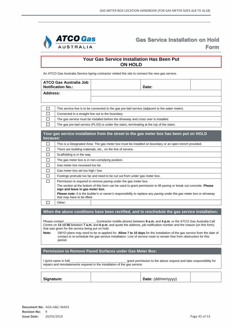
APPENDIX B. GAS SERVICE INSTALLATION ON HOLD FORM
GAS METER BOX LOCATION HANDBOOK (FOR GAS METER SIZES AL8 TO AL18)
Document No: AGA-A&C-MA03
Revision No: 9
Issue Date: 20/03/2019 Page 45 of 53
Gas Service Installation on Hold
Form
Your Gas Service Installation Has Been Put ON HOLD
An ATCO Gas Australia Service laying contractor visited this site to connect the new gas service.
ATCO Gas Australia Job Notification No.: Date:
Address:
This service line is to be connected to the gas pre-laid service (adjacent to the water meter).
Connected in a straight line out to the boundary.
The gas service must be installed before the driveway and cross over is installed.
The gas pre-laid service (PLSS) is under the stairs, terminating at the top of the stairs.
Your gas service installation from the street to the gas meter box has been put on HOLD because:
This is a Designated Area: The gas meter box must be installed on boundary or an open trench provided.
There are building materials, etc., on the line of service.
Scaffolding is in the way.
The gas meter box is in non-complying position.
Gas meter box recessed too far.
Gas meter box set too high / low.
Footings protrude too far and need to be cut out from under gas meter box.
Permission is required to remove paving under the gas meter box.
The section at the bottom of this form can be used to grant permission to lift paving or break out concrete. Please sign and leave in gas meter box.
Please note: it is the builder’s or owner’s responsibility to replace any paving under the gas meter box or driveway that may have to be lifted.
Other:
When the above conditions have been rectified, and to reschedule the gas service installation:
Please contact __________________ (contractor mobile phone) between 8 a.m. and 4 p.m. or the ATCO Gas Australia Call Centre on 13 13 56 between 7 a.m. and 6 p.m. and quote the address, job notification number and the reason (on this form) that was given for the service being put on hold.
Note: DBYD plans may need to be re-applied for. Allow 7 to 10 days for the installation of the gas service from the date of contact to re-schedule the gas service installation. Line of service route to remain free from obstruction for this period.
Permission to Remove Paved Surfaces under Gas Meter Box:
I (print name in full) ________________________________ grant permission to the above request and take responsibility for repairs and reinstatements required in the installation of the gas service.
Signature: Date: (dd/mm/yyyy)

GAS METER BOX LOCATION HANDBOOK (FOR GAS METER SIZES AL8 TO AL18)
Document No: AGA-A&C-MA03
Revision No: 9
Issue Date: 20/03/2019 Page 46 of 53
APPENDIX C. GAS SAFETY – DOS AND DON’TS
GAS METER BOX LOCATION HANDBOOK (FOR GAS METER SIZES AL8 TO AL18)
Document No: AGA-A&C-MA03
Revision No: 9
Issue Date: 20/03/2019 Page 47 of 53
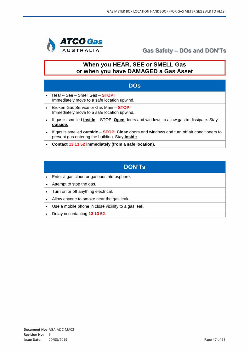
Gas Safety – DOs and DON'Ts
When you HEAR, SEE or SMELL Gas or when you have DAMAGED a Gas Asset
DOs
Hear – See – Smell Gas – STOP! Immediately move to a safe location upwind.
Broken Gas Service or Gas Main – STOP! Immediately move to a safe location upwind.
If gas is smelled inside – STOP! Open doors and windows to allow gas to dissipate. Stay outside.
If gas is smelled outside – STOP! Close doors and windows and turn off air conditioners to prevent gas entering the building. Stay inside.
Contact 13 13 52 immediately (from a safe location).
DON’Ts
Enter a gas cloud or gaseous atmosphere.
Attempt to stop the gas.
Turn on or off anything electrical.
Allow anyone to smoke near the gas leak.
Use a mobile phone in close vicinity to a gas leak.
Delay in contacting 13 13 52.

GAS METER BOX LOCATION HANDBOOK (FOR GAS METER SIZES AL8 TO AL18)
Document No: AGA-A&C-MA03
Revision No: 9
Issue Date: 20/03/2019 Page 48 of 53
APPENDIX D. FEEDBACK FORM
GAS METER BOX LOCATION HANDBOOK (FOR GAS METER SIZES AL8 TO AL18)
Document No: AGA-A&C-MA03
Revision No: 9
Issue Date: 20/03/2019 Page 49 of 53
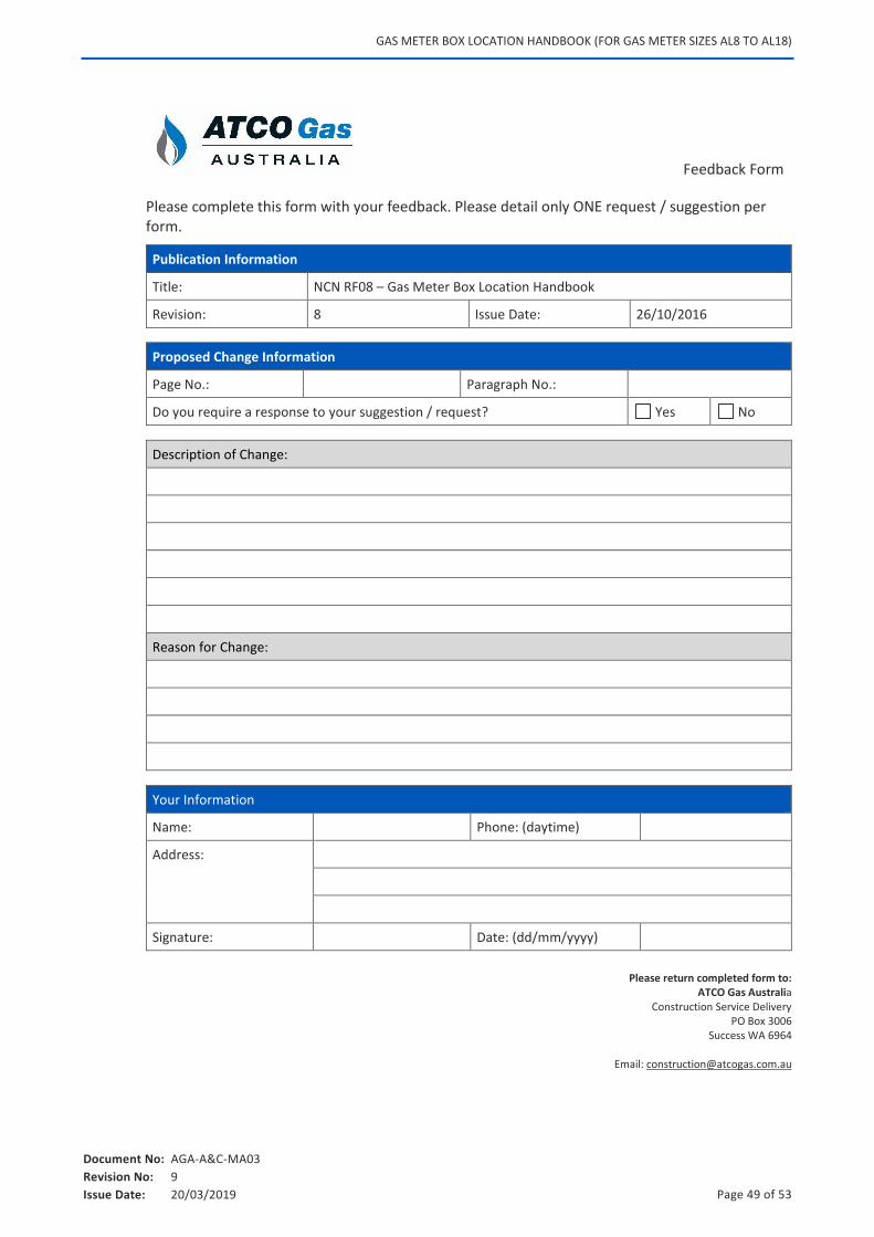
Feedback Form
Please complete this form with your feedback. Please detail only ONE request / suggestion per form.
Publication Information
Title: NCN RF08 – Gas Meter Box Location Handbook
Revision: 8 Issue Date: 26/10/2016
Proposed Change Information
Page No.: Paragraph No.:
Do you require a response to your suggestion / request? Yes No
Description of Change:
Reason for Change:
Your Information
Name: Phone: (daytime)
Address:
Signature: Date: (dd/mm/yyyy)
Please return completed form to:
ATCO Gas Australia Construction Service Delivery
PO Box 3006 Success WA 6964
Email: [email protected]