Embed Size (px)
Citation preview

500 Tennessee Waltz ParkwayAshland City, TN 37015
GAS FIRED COMMERCIAL COPPER BOILERSInstruction Manual
PRINTED 1115 321078-004
Thank you for buying this energy efficient boiler. We appreciate your confidence in our products.
MODELS: HW 300, 399, 420, 520, 670
FOR HYDRONIC HEATING AND HOT WATER SUPPLYUP - FLOW MODELS
INSTALLATION - OPERATION MAINTENANCE - LIMITED WARRANTY
INDOOR ONLY
WARNING: If the information in theseinstructions is not followed exactly, a fireor explosion may result causing propertydamage, personal injury or death.
Do not store or use gasoline or otherflammable vapors and liquids in thevicinity of this or any other appliance.
WHAT TO DO IF YOU SMELL GAS:
Do not try to light any appliance.
Do not touch any electrical switch; donot use any phone in your building.
Immediately call your gas supplierfrom a neighbor’s phone. Follow thegas supplier’s instructions.
If you cannot reach your gas supplier,call the fire department.
Installation and service must beperformed by a qualified installer,service agency or the gas supplier.
••
•
•
H

2
Air Requirements ............................................................................. 16
Unconfined Space ........................................................................... 16
Fresh Air Openings for Confined Spaces ........................................ 17
VENTING .............................................................................................. 21Standard Venting ............................................................................. 21
Sidewall Venting .............................................................................. 22
Venting System ................................................................................ 22
GAS SUPPLY CONNECTIONS ........................................................... 24Gas Manifold Pressure Regulators .................................................. 25
BOILER START UP AND OPERATIONS ............................................. 26Filling the System ............................................................................ 26
Precautions ...................................................................................... 26
Pilot and Main Burner ...................................................................... 26
Checking and Adjusting Input .......................................................... 28
TROUBLESHOOTING ......................................................................... 32GENERAL MAINTENANCE ................................................................. 40
Manual Reset High Limit Switch Continuity Test ............................. 40
Pressure Relief Valve Test ............................................................... 40
Cleaning and Flushing Instructions ................................................. 40
Venting Maintenance ....................................................................... 41
WIRING ................................................................................................ 42Wiring Connections ......................................................................... 42
PIPING DIAGRAMS ............................................................................. 47LIMITED WARRANTY .......................................................................... 61NOTES ................................................................................................. 63
TABLE OF CONTENTSTABLE OF CONTENTS .......................................................................... 2SAFE INSTALLATION, USE AND SERVICE.......................................... 3GENERAL SAFETY................................................................................ 4INTRODUCTION .................................................................................... 5
Abbreviations Used ........................................................................... 5Qualifications ..................................................................................... 5
DIMENSIONS AND CAPACITY DATA .................................................... 6CONTROL COMPONENTS ................................................................... 8BOILER INSTALLATION CONSIDERATIONS ..................................... 12
Hydronic System ............................................................................. 12Hot Water Supply Boiler System - General Water Line Connections ......................................................................................................... 12Closed Water Systems .................................................................... 13Thermal Expansion .......................................................................... 13Vent Valves ...................................................................................... 13Manifold Headers ............................................................................ 13Cooling Piping ................................................................................. 13Circulating Pump ............................................................................. 13
GENERAL REQUIREMENTS .............................................................. 15Required Ability ................................................................................ 15Location ........................................................................................... 15Replacing Existing Common Vented Boiler ..................................... 15Chemical Vapor Corrosion ............................................................... 16Installation Clearances .................................................................... 16Leveling ........................................................................................... 16System Connections ........................................................................ 16

3
The proper installation, use and servicing of this boiler is extremely important to your safety and the safety of others.Many safety-related messages and instructions have been provided in this manual and on your boiler to warn you and others of a potential injury hazard. Read and obey all safety messages and instructions throughout this manual. It is very important that the meaning of each safety message is understood by you and others who install, use, or service this boiler.
DANGER indicates an imminentlyhazardous situation which, if not avoided,will result in injury or death.
This is the safety alert symbol. It is used to alert you topotential personal injury hazards. Obey all safetymessages that follow this symbol to avoid possibleinjury or death.
WARNING indicates a potentially hazardoussituation which, if not avoided, could resultin injury or death.
CAUTION indicates a potentially hazardoussituation which, if not avoided, could result inminor or moderate injury.
CAUTION used without the safety alertsymbol indicates a potentially hazardoussituation which, if not avoided, could result inproperty damage.
WARNING
CAUTION
CAUTION
DANGER
All safety messages will generally tell you about the type of hazard, what can happen if you do not follow the safety message, and how to avoid the risk of injury.
IMPORTANT DEFINITIONS
Gas Supplier: The Natural Gas or Propane Utility or service who supplies gas for utilization by the gas burning appliances within this application. The gas supplier typically has responsibility for the inspection and code approval of gas piping up to and including the Natural Gas meter or Propane storage tank of a building. Many gas suppliers also offer service and inspection of appliances within the building.
SAFE INSTALLATION, USE AND SERVICE
APPROVALS
H

4
GROUNDING INSTRUCTIONS
This boiler must be grounded in accordance with the National Electrical Code, Canadian Electrical Code and/or local codes. Boiler is polarity sensitive; correct wiring is imperative for proper operation.This boiler must be connected to a grounded metal, permanent wiring system, or an equipment grounding conductor must be run with the circuit conductors and connected to the equipment grounding terminal or lead on the boiler.
CORRECT GAS
Make sure the gas on which the boiler will operate is the same as that speci fied on the boiler rating plate. Do not install the boiler if equipped for a different type of gas; con sult your supplier.
PRECAUTIONS
If the unit is exposed to the following, do not operate until all corrective steps have been made by a qualified service technician:
1. Exposure to fire.2. If damaged.3. Firing without water.4. Sooting.If the boiler has been exposed to flooding, it must be replaced.
PROPANE OR LIQUEFIED PETROLEUM (LP) GAS MODELS
Boilers for propane (LP) gas are different from natural gas models. A natural gas boiler will not function safely on propane (LP) gas and no attempt should be made to convert a boiler from natural gas to propane (LP) gas.
Propane (LP) gas must be used with great caution. It is highly explosive and heavier than air. It collects first in the low areas making its odor difficult to detect at nose level. If propane (LP) gas is present or even suspected, do not attempt to find the cause yourself. Leave the building, leaving doors open to ventilate, then call your gas supplier or service agent. Keep area clear until a service call has been made.
At times you may not be able to smell an propane (LP) gas leak. One cause is odor fade, which is a loss of the chemical odorant that gives propane (LP) gas its distinctive smell. Another cause can be your physical condition, such as having a cold or diminishing sense of smell with age. For these reasons, the use of a propane gas detector is recommended.If you experience an out of gas situation, do not try to relight boilers yourself. Call your local service agent. Only trained propane (LP) professionals should conduct the required safety checks in accordance with industry standards.
HIGH ALTITUDE INSTALLATIONS
Rated inputs are suitable up to 2000 feet (610 m) elevation. Consult the factory for installation at altitudes over 2000 feet (610 m).
GENERAL SAFETY

5
This design complies with the current edition of the ANSI Z21.13 low-pressure boiler standard.Compliance under this standard implies that when the boiler underwent test, the gas manifold and control assembly pro vided on the boiler met safe lighting and other performance criteria.Detailed installation diagrams are found in this manual. These diagrams will serve to provide the installer a reference for the materials and methods of piping necessary. It is essential that all water, gas piping and wiring be installed as shown on the diagrams. You should thoroughly read and understand this manual before installation and/or operation of this boiler.The factory warranty will be void if the boiler(s) have been improperly installed or operated.In addition to these instructions, the boiler(s) shall be installed in accordance with those installation regulations in force in the local area where the installation is to be made. These shall be carefully followed in all cases. Authorities having jurisdiction should be consulted before installations are made.In the absence of local codes, the installation must comply withthe current editions, as follows:In the United States:The National Fuel Gas Code, ANSI Z223.1/NFPA 54 and the National Electric Code, NFPA 70.In Canada:Installation Code CAN/CSA B149.1 and Canadian Electrical Code, CSA C22.1.Thank you for purchasing this boiler. Properly installed and maintained, it should give you years of trouble free service.
ABBREVIATIONS USED
Abbreviations found in this Instruction Manual include :• ANSI - American National Standards Institute• ASME - American Society of Mechanical Engineers• NEC - National Electrical Code• NFPA - National Fire Protection Association• UL - Underwriters Laboratory• CSA - Canadian Standards Association
INTRODUCTIONQUALIFICATIONS
QUALIFIED INSTALLER OR SERVICE AGENCYInstallation and service of this boiler requires ability equivalent to that of a Qualified Agency, as defined by ANSI below. In the field involved. Installation skills such as plumbing, air supply, venting, gas supply and electrical supply are required in addition to electrical testing skills when performing service.ANSI Z21.13 - CSA 4.9: “Qualified Agency” - “Any individual, firm, corporation or company that either in person or through a representative is engaged in and is responsible for (a) the installation, testing or replacement of gas piping or (b) the connection, installation, testing, repair or servicing of appliances and equipment; that is experienced in such work; that is familiar with all precautions required; and that has complied with all the requirements of the authority having jurisdiction.”If you are not qualified (as defined by ANSI above) and licensed or certified as required by the authority having jurisdiction to perform a given task do not attempt to perform any of the procedures described in this manual. If you do not understand the instructions given in this manual do not attempt to perform any procedures outlined in this manual.

6
DIMENSIONS AND CAPACITY DATA
EXTRA OPENINGFOR THERMOMETERA N D P R E S S U R E RELIEF VALVEHW-520 AND HW--670
DIMENSIONS IN INCHESMODELS
HW-300 HW-399 HW-420 HW-520 HW-670
A Overall height 65 (1651) 57-1/8 (1451) 57-1/8 (1451) 68-5/16 (1735) 67-1/2 (1715)
B Height to Top of Jacket 43-1/4 (1099) 45-1/8 (1146) 45-1/8 (1146) 56-1/4 (1429) 56-1/4 (1429)
C Floor to Center Line Water Inlet 36 (914) 38-3/4 (984) 38-3/4 (984) 46 (1168) 46 (1168)
D Diameter of Jacket 25-1/4 (641) 27 (686) 27 (686) 27 (686) 27 (686)
E Floor to Center Line Water Outlet 12 (305) 12 (305) 12 (305) 12 (305) 12 (305)
F Draft Diverter Outlet Diameter 8 (203) 10 (254) 10 (254) 10 (254) 12 (305)
G Floor to Center Line Gas Inlet 16-1/2 (419) 16-3/4 (425) 16-3/4 (425) 18 (457) 18 (457)
H Overall Depth 29-5/8 (753) 31-1/2 (800) 31-1/2 (800) 36-1/2 (927) 36-1/2 (927)
J Support Height 9 (229) 9 (229) 9 (229) 9 (229) 9 (229)
K Width of Control String (approx.) 14 (356) 14 (356) 14 (356) 11 (279) 11 (279)
L Pipe Size of Water Inlet (NPT) 1-1/4 1-1/2 1-1/2 2 2
M Pipe Size of Water Outlet (NPT) 1-1/4 1-1/2 1-1/2 2 2
N Pipe Size of Gas Inlet (NPT) 3/4 3/4 1 1 1
P Control String Plus 1/2 Jacket Diameter (approx.) 26-5/8 (676) 27-1/2 (699) 27-1/2 (699) 24-1/2 (622) 24-1/2 (622)
S Horizontal Length between Water Inlet and Outlet 5-3/8 (137) 5-1/2 (140) 5-1/2 (140) 5-3/4 (146) 5-3/4 (146)
T Control String from Jacket 5 (127) 5 (127) 5 (127) 7 (178) 7 (178)
Approximate shipping weight lbs. (Kilograms) 250 (113) 301 (137) 301 (137) 381 (173) 381 (173)
NOTE: All dimensions in inches (millimeters) except pipe size which is NPT
BTU INPUT/OUTPUTTEMPERATURE RISE AND PRESSURE DROP20 DEG. F
RISE30 DEG. F
RISE40 DEG. F
RISEMODELS INPUT RATING BTU/HR
NATURAL & PROPANE (LP) GASOUTPUT RATING BTU/HR
NATURAL & PROPANE (LP) GASGPM PD-FT
HEADGPM PD-FT
HEADGPM PD-FT
HEAD
HW 300 300,000 240,000 24 8 16 3 12 2
HW 399 399,000 319,200 32 16 21 7 16 5
HW 420 420,000 336,000 34 18 22 8 17 5.5
HW 520 520,000 416,000 42 12 28 5 21 4
HW 670 Nat 660,000 528,000 53 22 35 10 26 5.5
HW 670 Prop 670,000 536,000 54 22 36 10 27 5.5
TABLE 1. DIMENSIONS AND CAPACITY DATA
FIGURE 1. DIMENSIONS
TABLE 2. FLOW, HEAD AND TEMPERATURE RISE

7
TABLE 3. RECOVERY CAPACITIES
MODELS TYPE OF GAS
INPUT °F 20 40 50 60 70 80
BTU/HR KW °C (11) (22) (28) (33) (39) (44)
HW 300Natural
300,000 88GPH 1,455 727 582 485 416 364
Propane LPH 5,506 2,753 2,202 1,835 1,573 1,377
HW 399Natural
399,000 117GPH 1,935 967 774 645 553 484
Propane LPH 7,323 3,662 2,929 2,441 2,092 1,831
HW 420Natural
420,000 123GPH 2,036 1,018 815 679 582 509
Propane LPH 7,708 3,854 3,083 2,569 2,202 1,927
HW 520Natural
520,000 152GPH 2,521 1,261 1,008 840 720 630
Propane LPH 9,544 4,772 3,818 3,181 2,727 2,386
HW 670 Natural 660,000 193GPH 3,200 1,600 1,280 1,067 914 800
LPH 12,113 6,057 4,845 4,038 3,461 3,028
HW 670 Propane 670,000 196GPH 3,248 1,624 1,299 1,083 928 812
LPH 12,297 6,148 4,919 4,099 3,513 3,074
ELECTRICAL REQUIREMENTS
MODELS SUPPLY VOLTAGE (VOLTS)
FREQUENCY (HZ)
CURRENT (AMPS)
HW 300 120 60 12HW 399 120 60 12
HW 420 120 60 12HW 520 120 60 12HW 670 120 60 12
TABLE 4. ELECTRICAL REQUIREMENTS

8
FIGURE 2. COMPONENT LOCATIONS
CONTROL COMPONENTS

9
THERMAL BALANCER
Figure 5 shows the internal wiring of the thermal balancer. The device may be tested after disconnecting the four leads from their respective terminals on the unit.
1. Apply a test light to the yellow and red leads.• The lamp should light as the contact in this circuit is
normally closed when the resistor is cool.2. Apply a light to the black and yellow leads.
• The lamp should not light as the contact in this circuit is normally open when the resistor is cool.
3. Remove the test light.4. Apply 120 volts to the white and red leads which power the
1900 ohm resistor. After a warming period the contacts of the thermal balancer should operate.
5. Remove the test light.6. Apply the test light as described in steps 1 and 2.While the resistor is still warm the lamp indications should be the opposite as described previously.
MANUAL RESET HIGH LIMIT
This boiler is equipped with a manual reset high limit switch, located under the small cover on the side of the jacket, see Figure 6. This device provides positive shutdown of the boiler in the event of boiler or system malfunction. Should the surface temperature of the copper tubing heat exchanger reach 250°F (120°C), the high limit switch will activate, the gas control valve will close, the pilot and main burners will be extinguished. If the high limit switch should shut off unit, check the following conditions:
• No water in boiler.• Restricted water flow through the boiler.• Improper wiring (boiler firing without circulating pump
operating).• Pump failure.
After correcting failure condition remove the protector switch cover and push the reset button. The high limit switch may be reset after the coil surface cools to 6°F (3.3°C) below the trip setting.
AUTO RESET HIGH LIMIT
The high limit is a safety device wired in series with the ignition system. Set the high limit control to approximately 100°F above the maximum designed system temperature. If the boiler outlet water temperature should exceed the high limit setting, the main gas control valve will close but the circulating pump will continue to operate. Maximum adjustable setting is 115°C (239°F) cut-out with a 3°C (5°F) to 25°C (45°F) adjustable differential, see Figure 3.
INTERMITTENT IGNITION CONTROL MODULE
The Honeywell S-8600 control module contains the electronic components of the system and also serves as a control wiring system for the controls mounted on the boiler. The control module performs the following functions:1. Checks for safe-start by sensing for a false flame condition
on start-up.2. Generates a potential of 15,000 volts for spark ignition of the
pilot burner.3. Opens the pilot valve.4. Discontinues ignition spark when the pilot flame is
established. The S-8600 control used on propane gas models provides safety lockout if the pilot fails to ignite within the pilot flame establishing period. The S-8600 control used on natural gas models continues trial for ignition until pilot flame is established.
5. After proof of pilot flame, opens then main valve.6. On a power loss, shuts the boiler down. When power is
restored it will begin a new ignition cycle.7. On a loss of flame, shuts off main gas and starts trial for pilot
ignition.Please refer to TROUBLESHOOTING SECTION for more information.
FIGURE 3. AUTO RESET HIGH LIMIT
FIGURE 4. S-8600 INTERMITTENT IGNITION CONTROL MODULE (IID)
FIGURE 5. THERMAL BALANCER
FIGURE 6. HIGH LIMIT SWITCH

10
PRESSURE RELIEF VALVE
An ASME rated pressure relief valve is furnished with the boiler. A fitting for the pressure relief valve is provided in the top of the boiler. Never operate the heating elements without being certain the boiler is filled with water and a properly sized pressure relief valve is installed in the pressure relief valve opening provided.The pressure rating of the pressure relief valve should be equal to or less than the rated pressure capacity of any component in the system including the boiler. Should the valve need to be replaced, call the toll free phone number listed on the back of this manual for further technical assistance.
A discharge pipe from the pressure relief valve should terminate at an adequate floor drain. Do not thread, plug, or cap the end of the drain line.
The Discharge Pipe:• Shall not be smaller in size than the outlet pipe size of the
valve, or have any reducing couplings or other restrictions.• Shall not be plugged or blocked.• Shall not be exposed to freezing temperatures.• Shall be of material listed for hot water distribution.• Shall be installed so as to allow complete drainage of both
the pressure relief valve and the discharge pipe.• Must terminate a maximum of six inches above a floor
drain or external to the building. In cold climates, it is recommended that the discharge pipe be terminated at an adequate drain inside the building.
• Shall not have any valve or other obstruction between the pressure relief valve and the drain.
Once the boiler is installed and filled with water and the system is pressurized, manually test the operation of the pressure relief valve.
Explosion HazardPressure Relief Valve mustcomply with ASME code.
Properly sized Pressure ReliefValve must be installed inopening provided.
Can result in overheating andexcessive tank pressure.
Can cause serious injury or death.
Water Damage Hazard
Pressure Relief Valve discharge pipe mustterminate at adequate drain.
•
CAUTION
If any pressure relief valve is replaced, the replacement valve must comply with the current editions of the ASME Boiler and Pressure Vessel Code, Section IV or CSA B51, as applicable. Select a pressure relief valve with a discharge NOT less than the boiler input, and a pressure rating NOT exceeding the working pressure of any component in the system.All HW models ship factory standard with a 125 psi relief valve for hot water supply applications an optional 50 psi relief valve is available for units to be used for space heating applications.An ASME rated temperature and pressure relief valve must be installed on each and every water storage tank in a hot water supply system.The storage tank temperature and pressure (T & P) relief valve must comply with the applicable construction provisions of the Standard for Relief valves and Automatic Gas Shutoff Devices for Hot Water Supply Systems, Z21.22 - CSA 4.4. The T & P valve must be of the automatic reset type and not embody a single-use type of fusible plug, cartridge or linkage.The T & P relief valve should have a maximum temperature rating of 100°C (210°F), a pressure rating NOT exceeding the lowest rated working pressure of any system component, and a discharge capacity exceeding the total input of the water boilers supplying water to the storage tank.Locate the T & P relief valve (a) in the top of the storage tank or (b) in the side of the tank on centerline within upper 6 inches from the top of the tank. See Figure 30 to Figure 43 on Pages 47 to 60. Tapping shall be threaded in accordance with the latest version of the Standard for Pipe Threads, General Purpose (inch), ANSI/ASME B.120.1.

11
USE ANTI-SCALD VALVE(S) in the hot water system to reduce the risks of scalds at points of use such as lavatories, sinks and bathing facilities.A change in water temperature in the storage tank lower than the Tank Temperature Control setting will cause the sensor to close its contacts and consequently energize the boiler.If the Tank Temperature Control is out of calibration, replace it with a new one; do not attempt to fix this control.
THERMOMETERS
Thermometers should be obtained and field installed as shown in the installation diagrams.Thermometers are installed in the system as a means of detecting a possible liming condition in the boiler. An increase of 5°F (3°C) over the normal temperature rise through the boiler is an indication that lime is present. The term "temperature" designates the difference between the boiler inlet and outlet water temperature.An increase of 5°F (3°C) above the recorded temperature rise may signify a liming condition in the coils or heat exchanger. Refer to Cleaning and Flushing Instructions on Page 40 for deliming instructions.Record temperature rise at initial start-up for future reference.
DRAIN VALVE (NOT SUPPLIED)
A drain valve must be obtained and installed on each boiler and tank for draining purposes.
TANK TEMPERATURE CONTROL
The water temperature in the storage tank is controlled by the Tank Temperature Control. The sensing element is mounted inside the hot water storage tank.
The tank temperature control is adjustable from 100°F (37.7°C)to 220°F (104.4°C). It is recommended that lower water temperatures be used to avoid the risk of scalding. It is further recommended, in all cases, that the water temperature be set for the lowest temperature which satisfies the user’s hot water needs. This will also provide the most energy efficient operation of the boiler and minimize scale formation.The boiler should be located in an area where the general public does not have access to set temperatures. Setting the water temperature at 120°F (49°C) will reduce the risk of scalds. Some people are more likely to be permanently injured by hot water than others. These include the elderly, children, the infirm and the physically/mentally disabled. Table 5 shows the approximate time-to-burn relationship for normal adult skin. If anyone using hot water provided by the boiler being installed fits into one of these groups or if there is a local code or state law requiring a certain water temperature at the point of use, then special precautions must be taken. Contact a qualified service technician or qualified agency.
Water Temperature °F (°C)
Time for 1st Degree Burn (Less Severe Burns)
Time for Permanent Burns 2nd & 3rd Degree
(Most Severe Burns)
110 (43) (normal shower temp.)
116 (47) (pain threshold)
116 (47) 35 minutes 45 minutes
122 (50) 1 minute 5 minutes
131 (55) 5 seconds 25 seconds
140 (60) 2 seconds 5 seconds
149 (65) 1 second 2 seconds
154 (68) instantaneous 1 second
(U.S. Government Memorandum, C.P.S.C., Peter L. Armstrong, Sept. 15, 1978)
Water temperature over 125°F (52°C)can cause severe burns instantlyresulting in severe injury or death.
Children, the elderly and thephysically or mentally disabled are athighest risk for scald injury.
Feel water before bathing orshowering.
Temperature limiting devices such asmixing valves must be installedwhen required by codes and toensure safe temperatures at fixtures.
TABLE 5. TEMPERATURE AND TIME TO PRODUCE BURNS

12
BOILER INSTALLATION CONSIDERATIONSHYDRONIC SYSTEM
All modern hydronic type boilers are exceptionally fast heating units. The low water volumes in relation to firing rates require special attention to water flow rates for smooth, efficient operation. These considerations for the A. O. Smith copper heat exchanger boilers are covered below.Conventional 20 ºF (10 ºC) drop in systems for a fully loaded boiler will maintain the following approximate flow rates:
MODELS GPM (LPM)HW-300 24 (91)HW-399 32 (121)HW-420 34 (127)HW-520 42 (158)HW-670 54 (203)
Figure 30 to Figure 43 on Pages 47 to 60 show typical installations of the boiler with pipe sizing and circulating pump selected by the installer to provide adequate water flow whenever the boiler is firing.In a system with several large zones of which any might be smaller than approximately 1/3 of the system should include a hydronic balancer as shown in the piping diagrams. The balancer connects between the system supply and the return line before the circulating pump inlet. Adjustment of the balancing cock should permit adequate boiler flow rate when only the smallest zone is in operation.Attention should be given to balancing inputs and water flow rates where wide variations of system flow rates can occur.The recommended minimum flow rates that will result in approximately 50 ºF (30 ºC) temperature rise across the boiler are as follows:
MODELS GPM (LPM)HW-300 10 (36)HW-399 13 (49)HW-420 13 (49)HW-520 17 (63)HW-670 21 (81)
Pipe sizing and boiler loop pump selection data are shown in Table 8 for several different temperature rises across the boilers.
MODEL TEMP. RISE °F (°C) GPM *PUMP
SIZEPIPE SIZE
HW-300
20 (10) 30 (15) 30 (15)40 (20)
24161612
1-1/2" PR150125100
2"1-1/2"1-1/4"
1"
HW-399
20 (10)35 (15)40 (20)40 (20)
32181616
60-131-1/2" HV
150125
2"1-1/2"1-1/2"1-1/4"
HW-420
20 (10)35 (15)40 (20)40 (20)
34191717
60-131-1/2" HV
150125
2"1-1/2"1-1/2"1-1/4"
HW-520
20 (10)20 (10)35 (17)40 (20)
42422421
2-1/2"1-1/2" HV1-1/2" HV
150
2-1/2"2"
1-1/2"1-1/2"
HW-670
20 (10)30 (15)35 (17)40 (20)
54363127
60-132-1/2"
2"1-1/2" HV
3"2-1/2"
2"1-1/2"
NOTE: Pipe loop sizes and pump selections based on 50 equivalent feet of pipe and fittings.
*All pump sizes listed are B & G model numbers.
HOT WATER SUPPLY BOILER SYSTEM - GENERAL WATER LINE CONNECTIONS
Piping diagrams will serve to provide the installer with a reference for the materials and methods of piping necessary for installation. It is essential that all water piping be installed and connected as shown on the diagrams. Check the diagrams to be used thoroughly before starting installation to avoid possible errors and to minimize time and material cost. It is essential that all water piping be installed and connected as shown on the diagrams. Figure 30 to Figure 43 on Pages 47 to 60.These boilers can be used ONLY in a forced circulation hot water heating system. Since most forced circulation systems will be of the closed type, install the water supply line as shown on piping diagrams, Fast filling of large pipe, old radiator installations and pressure purging of series loop systems (where high pressures are not available) requires bypassing of the pressure reducing valve. Generally, pressure purging is not possible with a well pump system. High point air venting is essential.If the system is of the open type, a pressure reducing valve will not be required as the water supply to the system will be controlled by a manually operated valve. An overhead surge tank is required.
TABLE 6. WATER FLOW RATES
TABLE 7. MINIMUM WATER FLOW RATES RESULTING IN TEMPERATURE RISE
TABLE 8. PUMP AND PIPE SIZING DATA (PIPING FROM TEES IN MAIN TO BOILER BRANCHES)

13
COOLING PIPING
When the boiler is used in conjunction with a refrigeration system it must be installed so that the chilled medium is piped in parallel with the boiler with appropriate valves to prevent the chilled medium from entering the boiler, see Figure 7.Water temperature in the heating system must be reduced to less than 1000F (38°C) before cooling system is started, or damage to the chiller unit may occur.
FIGURE 7. SCHEMATIC SHOWING PROPER PIPING ISOLATION OF THE BOILER FROM THE CHILLER
If the boiler is connected to chilled water piping or its heating coils are exposed to refrigerated air, the boiler piping system must be equipped with flow valves or other automatic means to prevent gravity circulation through the boiler during the cooling cycle.
CIRCULATING PUMP
Constant circulating pump operation of the boiler voids the warranty. Constant water flow through the unit will “wash” away the copper’s natural protective coating. This is called velocity erosion. This erosion is not as great a problem when intermittent circulating operation is used per the recommended installation procedure. Constant circulation of water through the building’s system main is permissible as long as the water does not constantly flow through the boiler. Only all bronze or stainless steel circulating pumps are to be used with the unit when it is installed in hot water supply systems.
FIGURE 8. A TYPICAL CIRCULATING PUMP
Although each circulating pump that requires oiling is oiled and operated by the manufacturer, It must be oiled again before operated. See Figure 8 above.Refer to the pump manufacturer’s instructions for lubrication requirements.
CLOSED WATER SYSTEMS
Water supply systems may, because of code requirements or such conditions as high line pressure, among others, have installed devices such as pressure reducing valves, check valves, and back flow preventers. Devices such as these cause the water system to be a closed system.
THERMAL EXPANSION
As water is heated, it expands (thermal expansion). In a closed system the volume of water will grow when it is heated. As the volume of water grows there will be a corresponding increase in water pressure due to thermal expansion. Thermal expansion can cause premature tank failure (leakage). This type of failure is not covered under the limited warranty. Thermal expansion can also cause intermittent Temperature-Pressure Relief Valve operation: water discharged from the valve due to excessive pressure build up. This condition is not covered under the limited warranty. The Temperature-Pressure Relief Valve is not intended for the constant relief of thermal expansion.A properly sized thermal expansion tank must be installed on all closed systems to control the harmful effects of thermal expansion. Contact a local plumbing service agency to have a thermal expansion tank installed. An expansion tank or a similar device may be required in the inlet supply line between the boiler and the meter or valve to compensate for the thermal expansion of water under supply pressure, see Piping Diagrams section on Page 47.An air separator as shown in the piping diagrams is recommended especially for modern commercial hydronic systems.
VENT VALVES
It is recommended that automatic, loose key or screwdriver type vent valves be installed at each convector or radiator.
MANIFOLD HEADERS
Split systems with individual supply and return lines from the boiler room should normally have this piping connected to supply and return manifold headers near the boiler. To achieve good water distribution with maximum pressure drop for several circuits, manifolds of at least 2-1/2" (64 mm) diameter are suggested on HW-399, HW-420, HW-520 and HW-670 units. HW-300 units should have 1-1/2" (38 mm) diameter manifolds.The circuits should be spaced on the header at a minimum of 3" (76 mm) center to center. Install a balancing cock in each return line.Manifold headers are recommended for split systems with or without zone valves and also those installations with zone circulating pumps. If the system is to be split at remote points, good practice requires special attention be given to main pipe sizing to allow balancing of water flow.The boiler piping system of a hot water boiler connected to heating coils located in air handling units where they may be exposed to refrigerated air circulation must be equipped with flow control valves or other automatic means to prevent gravity circulation of the boiler water during the cooling cycle.

14
FLOW SWITCH
The flow switch is a safety device which must be installed at the water outlet of the unit to prevent main burner operation in the event of inadequate water flow through the unit.An accessory package containing a flow switch is available for this application.This switch may be mounted in a horizontal pipe line or a vertical pipe line with upward water flow. Do not install the switch where the water flow is downward.For proper performance mount the switch in a section of pipe where there is a straight run of at least 5 pipe diameters on each side of the flow switch (i.e. do not locate adjacent to valves, elbows, orifices, etc.).The flow switch shall be mounted in a standard 1-1/2" x 1-1/2" x 1" tee for a 1-1/2" pipe application. For larger pipe sizes use a reducing tee in order to keep the switch as close to the pipe as possible. Install the flow switch in the branch (top) opening of the reducing tee and provide adequate paddle length in the flow stream. For example in a 2" pipe installation use a 2" x 2" x 1" reducing tee. For 2", or 3" pipe use paddle segments as supplied. For other pipe sizes (i.e. 1-1/4", 1-1/2" and 2-1/2") trim the paddle to the proper pipe size, see Figure 9 below. If a standard tee is used, install a face or hex bushing in the top opening. The paddle must be adjusted or trimmed to the size of the pipe in which it will be installed.Any part of the paddle must not touch the pipe or any restrictions in the pipe. Screw the flow switch in position so the flat of the paddle is at right angles to the flow. The arrow on the side case must point in the direction of the flow.
Minimum Pipe Rate
Model NumberContacts Closed
(Flow)Contacts Open
(No Flow)GPM LPM GPM LPM
HW-300 5.8 22.0 3.7 14.0
HW-399 7.5 28.4 5.0 18.9
HW-420 7.5 28.4 5.0 18.9
HW-520 13.7 51.9 9.5 36.0
HW-670 13.7 51.9 9.5 36.0
The flow switch may be field adjusted to obtain higher minimum flow rates than those shown inTable 9.To adjust the flow rate setting:1. Remove the flow switch cover.2. For higher flow rate - turn the range adjusting screw
clockwise.3. For lower flow rate-turn the range adjusting screw
counterclockwise.The switch is factory set at approximately the minimum flow rate, refer to Table 9. It must not be set lower than the factory setting as this may result in the switch failing to return at a 'no flow' condition.4. Replace flow switch cover. Where units are installed in
multiples, each boiler must be individually protected by a flow switch.
TABLE 9. FLOW SWITCH
FIGURE 9. FLOW SWITCH

15
GENERAL REQUIREMENTSREQUIRED ABILITY
Installation or service of this boiler requires ability equivalent to that of a qualified service technician in the field involved. Plumbing, air supply, venting, gas supply, and electrical work are re quired.LOCATION
When installing the boiler, consideration must be given to proper location. The location selected should provide ade quate air supply and be as centralized with the piping system as possible. This location should also be such that the gas ignition system components are protected from water dripping, spraying, etc.) during boiler operation and service (circulating pump replacement, control replacement, etc.).
Some local codes permit operation of gas appliances if installed 18 inches or more above the floor. This may reduce the risk if location in such an area cannot be avoided.A hot water boiler installed above radiation level or as required by the authority having jurisdiction, must be provided with a low water cutoff device at the time of boiler installation.
REPLACING EXISTING COMMON VENTED BOILER
When an existing boiler is removed from a common venting system, the common venting system is likely to be too large for proper venting of the appliances remaining connected to it. At the time of removal of an existing boiler, the following steps shall be followed with each appliance remaining connected to the common venting system placed in operation, while the other appliances remaining connected to the common venting system are not in operation.1. Seal any unused openings in the common venting system.2. Visually inspect the venting system for proper size and
horizontal pitch and determine there is no blockage or restriction, leakage, corrosion and other deficiencies which could cause an unsafe condition.
3. Insofar as is practical, close all building doors and windows and all doors between the space in which the appliances remaining connected to the common venting system are located and other spaces of the building. Turn on clothes dryers and any appliance not connected to the common venting system. Turn on any exhaust fans, such as range hoods and bathroom exhausts, so they will operate at maximum speed. Do not operate a summer exhaust fan. Close fireplace dampers.
4. Place in operation the appliance being inspected. Follow the lighting instructions. Adjust thermostat so appliance will operate continuously.
5. Test for spillage at the draft hood relief opening after 5 minutes of main burner operation. Use the flame of a match or candle, or smoke from a cigarette, cigar or pipe.
6. After it has been determined that each appliance remaining connected to the common venting system properly vents when tested as outlined above, return doors, windows, exhaust fans, fireplace dampers and any other gas-burning appliance to their previous condition of use.
7. Any improper operation of the common venting system should be corrected so the installation conforms with the National Fuel Gas Code, ANSI Z223.1/NFPA 54 and/or CSA B149.1, Installation Codes. When resizing any portion of the common venting system, the common venting system should be resized to approach the minimum size as determined using the appropriate tables in the National Fuel Gas Code, ANSI Z223.1/NFPA 54 and/or CSA B149 .1, Installation Codes.

16
CHEMICAL VAPOR CORROSION
Boiler corrosion and component failure can be caused by the heating and breakdown of airborne chemical vapors. Spray can propellants, cleaning sol vents, refrigerator and air conditioning refrig erants, swimming pool chemicals, calcium and sodium chloride (water softener salt), waxes, and process chemicals are typical compounds which are potentially corrosive. These materials are corrosive at very low concentration levels with little or no odor to reveal their presence.Products of this sort should not be stored near boiler. Also, air which is brought in contact with boiler should not contain any of these chemicals. If necessary, uncontaminated air should be obtained from remote or outside sources. Failure to observe this requirement will void warranty.
INSTALLATION CLEARANCES
These boilers are approved for installation on combustible flooring in an alcove with minimum clearance to combustibles of:
HW300
HW399
HW420
HW520
HW670
TOP 28" (711.2) 28" (711.2) 24" (609.6) 24" (609.6) 24" (609.6)
SIDES 6" (152.4) 6" (152.4) 24" (609.6) 24" (609.6) 24" (609.6)
REAR 6" (152.4) 6" (152.4) 24" (609.6) 24" (609.6) 24" (609.6)
VENT 6" (152.4) 6" (152.4) 6" (152.4) 6" (152.4) 6" (152.4)
2 inches (51 mm) clearance is allowable from combustible construction for hot water pipes.Sufficient area should be provided at the front and rear of the unit for proper servicing. Clearances of 24 inches (609.4 mm) in the rear and 48 inches (1,219 mm) in the front are required by code. In a utility room installation, the door shall be wide enough to allow the boiler to enter or to permit the replacement of another appliance such as a boiler.
LEVELING
Each unit should be checked after installation to be certain that it is level prior to starting the unit.If the unit is not level, obtain and insert shims under the legs of the unit to correct this condition.
SYSTEM CONNECTIONS
The system installation must conform to these instructions and to the requirements of the local code authority having jurisdiction. Good practice requires that all heavy piping be supported.
TABLE 10. INSTALLATION CLEARANCES
AIR REQUIREMENTS
Breathing Hazard - Carbon Monoxide GasInstall appliance in accordance withthe Instruction Manual and NFPA 54 orCAN/CSA-B149.1.To avoid injury, combustion and ventilationair must be taken from outdoors.Do not place chemical vapor emittingproducts near the boiler.
Breathing carbon monoxide can cause brain damage ordeath. Always read and understand instruction manual.
For safe operation an adequate supply of fresh uncontaminated air for combustion and ventilation must be provided.An insufficient supply of air can cause recirculation of combustion products resulting in contamination that may be hazardous to life. Such a condition often will result in a yellow, luminous burner flame, causing sooting of the combustion chamber, burners and flue tubes and creates a risk of asphyxiation.Do not install the boiler in a confined space unless an adequate supply of air for combustion and ventilation is brought in to that space using the methods described in the Confined Space section that follows. Never obstruct the flow of ventilation air. If you have any doubts or questions at all, call your gas supplier. Failure to provide the proper amount of combustion air can result in a fire or explosion and cause property damage, serious bodily injury or death.
UNCONFINED SPACE
An unconfined space is one whose volume is not less than 50 cubic feet per 1,000 Btu/hr (4.8 cubic meters per kW) of the total input rating of all appliances installed in the space. Rooms communicating directly with the space, in which the appliances are installed, through openings not furnished with doors, are considered a part of the unconfined space.Makeup air requirements for the operation of exhaust fans, kitchen ventilation systems, clothes dryers and fireplaces shall also be considered in determining the adequacy of a space to provide combustion, ventilation and dilution air.UNUSUALLY TIGHT CONSTRUCTIONIn unconfined spaces in buildings, infiltration may be adequate to provide air for combustion, ventilation and dilution of flue gases. However, in buildings of unusually tight construction (for example, weather stripping, heavily insulated, caulked, vapor barrier, etc.) additional air must be provided using the methods described in the Confined Space section that follows.

17
CONFINED SPACE
A confined space is one whose volume is less than 50 cubic feet per 1,000 Btu/hr (4.8 cubic meters per kW) of the total input rating of all appliances installed in the space.Openings must be installed to provide fresh air for combustion, ventilation and dilution in confined spaces. The required size for the openings is dependent on the method used to provide fresh air to the confined space and the total Btu/hr input rating of all appliances installed in the space.
DIRECT VENT BOILERSBoilers installed in a direct vent configuration that derive all air for combustion from the outdoor atmosphere through sealed intake air piping are not factored in the total boiler input Btu/hr calculations used to determine the size of openings providing fresh air into confined spaces.
EXHAUST FANSWhere exhaust fans are installed, additional air shall be provided to replace the exhausted air. When an exhaust fan is installed in the same space with a boiler, sufficient openings to provide fresh air must be provided that accommodate the requirements for all appliances in the room and the exhaust fan. Undersized openings will cause air to be drawn into the room through the boiler’s vent system causing poor combustion. Sooting, serious damage to the boiler and the risk of fire or explosion may result. It can also create a risk of asphyxiation.
LOUVERS AND GRILLESThe free areas of the fresh air openings in the instructions that follow do not take in to account the presence of louvers, grilles or screens in the openings.The required size of openings for combustion, ventilation and dilution air shall be based on the “net free area” of each opening. Where the free area through a design of louver or grille or screen is known, it shall be used in calculating the size of opening required to provide the free area specified. Where the louver and grille design and free area are not known, it shall be assumed that wood louvers will have 25% free area and metal louvers and grilles will have 75% free area. Non motorized louvers and grilles shall be fixed in the open position.
FRESH AIR OPENINGS FOR CONFINED SPACES
The following instructions shall be used to calculate the size, number and placement of openings providing fresh air for combustion, ventilation and dilution in confined spaces. The illustrations shown in this section of the manual are a reference for the openings that provide fresh air into confined spaces only. Do not refer to these illustrations for the purpose of vent installation. See Venting section on Page 21 for complete venting installation instructions.
OUTDOOR AIR THROUGH TWO OPENINGS
The confined space shall be provided with two permanent openings, one commencing within 12 inches (300 mm) of the top and one commencing within 12 inches (300 mm) of the bottom of the enclosure. The openings shall communicate directly with the outdoors. See Figure 10.Each opening shall have a minimum free area of 1 square inch per 4,000 Btu/hr (550 mm2 per kW) of the aggregate input rating of all appliances installed in the enclosure. Each opening shall not be less than 100 square inches (645 cm2). OUTDOOR AIR THROUGH ONE OPENING
Alternatively a single permanent opening, commencing within 12 inches (300 mm) of the top of the enclosure, shall be provided. See Figure 11. The boiler shall have clearances of at least 1 inch (25 mm) from the sides and back and 6 inches (150 mm) from the front of the appliance. The opening shall directly communicate with the outdoors or shall communicate through a vertical or horizontal duct to the outdoors or spaces that freely communicate with the outdoors and shall have a minimum free area of the following:
1. 1 square inch per 3000 Btu/hr (700 mm2 per kW) of the total input rating of all appliances located in the enclosure, and
2. Not less than the sum of the areas of all vent connectors in the space.
FIGURE 10. OUTDOOR AIR THROUGH TWO OPENINGS
FIGURE 11. OUTDOOR AIR THROUGH ONE OPENING

18
The confined space shall be provided with two permanent vertical ducts, one commencing within 12 inches (300 mm) of the top and one commencing within 12 inches (300 mm) of the bottom of the enclosure. The vertical ducts shall communicate directly with the outdoors. See Figure 13.Each duct opening shall have a minimum free area of 1 square inch per 4,000 Btu/hr (550 mm2 per kW) of the aggregate input rating of all appliances installed in the enclosure. When ducts are used, they shall be of the same cross sectional area as the free area of the openings to which they connect. The minimum dimension of rectangular air ducts shall be not less than 3 inches.
AIR FROM OTHER INDOOR SPACES
The confined space shall be provided with two permanent openings, one commencing within 12 inches (300 mm) of the top and one commencing within 12 inches (300 mm) of the bottom of the enclosure. See Figure 14.Each opening shall communicate directly with an additional room(s) of sufficient volume so that the combined volume of all spaces meets the criteria for an Unconfined Space.Each opening shall have a minimum free area of 1 square inch per 1,000 Btu/hr (1100 mm2 per kW) of the aggregate input rating of all appliances installed in the enclosure. Each opening shall not be less than 100 square inches (645 cm2).
OUTDOOR AIR THROUGH TWO HORIZONTAL DUCTS
The confined space shall be provided with two permanent horizontal ducts, one commencing within 12 inches (300 mm) of the top and one commencing within 12 inches (300 mm) of the bottom of the enclosure. The horizontal ducts shall communicate directly with the outdoors. See Figure 12.Each duct opening shall have a minimum free area of 1 square inch per 2,000 Btu/hr (1100 mm2 per kW) of the aggregate input rating of all appliances installed in the enclosure.When ducts are used, they shall be of the same cross sectional area as the free area of the openings to which they connect. The minimum dimension of rectangular air ducts shall be not less than 3 inches.
OUTDOOR AIR THROUGH TWO VERTICAL DUCTS
The illustrations shown in this section of the manual are a reference for the openings that provide fresh air into confined spaces only.Do not refer to these illustrations for the purpose of vent installation.
FIGURE 12. OUTDOOR AIR THROUGH TWO HORIZONTAL DUCTS
FIGURE 13. OUTDOOR AIR THROUGH TWO VERTICAL DUCTS
FIGURE 14. AIR FROM OTHER INDOOR SPACES

19
Fittings and unions in gas line must be of metal to metal type.Apply joint compounds (pipe dope) sparingly and only to the male threads of pipe joints. Do not apply compound to the first two threads. Use compounds resistant to the action of liquefied petroleum gases. The boiler and its gas connection must be leak tested before placing the boiler in operation.SIZING GAS SUPPLY LINE (FOR SINGLE BOILER INSTALLATIONS AND FOR INSTALLATIONS OF MULTIPLES OF TWO OR THREE OF SAME SIZE BOILERS).Use Table 11 or CAN/CSA B149.1 (current edition) to size iron pipe or equivalent gas supply line. Table 11 is based on a pressure drop of 0.3 inches of water and a specific gravity of 0.60 approximately that of natural gas. (Propane (LP) gas has an S.G. of about 1.53). If the service pressure is five inches water column or less, use one pipe size larger in order to minimize pressure drop in the line.
Distance from Gas
Meter
Nominal Iron Pipe Size (Inches)
1/2 3/4 1 1 1/4 1 1/2 2 2 1/2 3 410 (3) 132 278 520 1,050 1,600 3,050 4,800 8,500 17,50020 (6) 92 190 350 730 1,100 2,100 3,300 5,900 12,00030 (9) 73 152 285 590 890 1,650 2,700 4,700 9,70040(12) 63 130 245 500 760 1,450 2,300 4,100 8,30050 (15) 56 115 215 440 670 1,270 2,000 3,600 7,40060 (18) 50 105 195 400 610 1,150 1,850 3,250 6,80070 (21) 46 96 180 370 560 1,050 1,700 3,000 6,20080 (24) 43 90 170 350 530 990 1,600 2,800 5,80090 (27) 40 84 160 320 490 930 1,500 2,600 5,400
100 (30) 38 79 150 305 460 870 1,400 2,500 5,100125 (38) 34 72 130 275 410 780 1,250 2,200 4,500150 (45) 31 64 120 250 380 710 1,130 2,000 4,100175 (53) 28 59 110 225 350 650 1,050 1,850 3,800200 (60) 26 55 100 210 320 610 980 1,700 3,500
*The heating value of Natural Gas is approximately 1,050 Btu/Ft.3.Propane (LP) Gas has a heating value of approximately 2,500 Btu/Ft3.
1 cu. meter=35.31 cu. feet.
Where it is necessary to use more than the average number of pipe fittings i.e. elbows, tees, and valves in gas supply line, use a pipe larger than specified to compensate for increased pressure drop.
GAS CONNECTIONS
Make sure the gas on which boiler is to operate is same as that specified on the rating plate. Do not install boiler if equipped for a different type of gas. Consult your gas supplier.This boiler is not intended to operate at gas supply pressure other than shown on the rating plate. A lock-up or positive shut-off type regulator must be installed in gas supply line. For proper gas regulation the lock-up style regulators must be installed no closer than a minimum of 3 feet from the boiler and a maximum of 8 feet away from the boiler. Exposure to higher gas supply pressure may cause damage to gas control valves which can result in fire or explosion. If overpressure has occurred such as through improper testing of gas lines or emergency malfunction of supply system, the gas control valves must be checked for safe operation. Make sure that the outside vents on supply regulators and the safety vent valves are protected against blockage. These are parts of the gas supply system, not boiler. Vent blockage may occur during ice build-up or snowstorms.The boiler must be isolated from the gas supply piping system by closing its main manual gas shut off valve during any pressure testing of the gas supply piping system at test pressures equal to or less than 1/2 psig.Disconnect the boiler and its main manual gas shut-off valve from the gas supply piping during any pressure testing of the gas supply system over 1/2 psig. The gas supply line must be capped when not connected to the boiler.It is important to guard against gas control valve fouling from contaminants in the gas ways. Such fouling may cause improper operation, fire or explosion. If copper supply lines are used they must be approved for gas service.When local codes require a main manual shut-off valve outside the boiler jacket, a suitable main manual shut-off valve must be installed in a location complying with those codes.Before attaching gas line be sure that all gas pipe is clean on inside. To trap any dirt or foreign material in the gas supply line, a sediment trap must be incorporated in piping. The sediment trap must be readily accessible and not subject to freezing conditions. Install in accordance with recommendations of serving gas supplier. Refer to the current edition of the National Fuel Gas Code, ANSI Z223.1/NFPA 54 or the Natural Gas and Propane Installation Code, CAN/CSA B149.1Size of gas supply piping may be larger than heater connection on installations where a significant run of piping is required.To prevent damage, care must be taken not to apply too much torque when attaching gas supply pipe to boiler gas inlet. When installing and tightening gas piping use a second wrench to hold the gas control valve to keep the valve from turning. To prevent damage to the gas control valve do not use pipe wrench on the valve body.
TABLE 11. MAXIMUM CAPACITY OF PIPE IN CUBIC FEET OF GAS PER HOUR (BASED UPON A PRESSURE DROP OF 0.3
INCH WATER COLUMN AND 0.6 SPECIFIC GRAVITY GAS)

20
TAB
LE 1
2. S
UG
GES
TED
PIP
E SI
ZE F
OR
MU
LTIP
LE G
AS
APP
LIA
NC
ES (N
ATU
RA
L G
AS)
N
omin
al
Max
imum
Cap
acity
of P
ipe
in B
TU/h
r and
kW
for G
as P
ress
ures
of 1
4 in
. W.C
. (0.
5 ps
i) or
Les
s an
d I
ron
Pip
e a
Pre
ssur
e D
rop
of 0
.5 in
. W.C
. (b
ased
on
0.60
Spe
cific
Gra
vity
Gas
w/H
eatin
g Va
lue
of 1
,000
BTU
’s/F
t3)
S
ize
Leng
th o
f Pip
e in
Fee
t (M
eter
s)
(Inch
es)
10
(3.0
5)
20 (6
.1)
30 (9
.14)
40
(12.
19)
50 (1
5.24
) 60
(18.
29) 7
0 (2
1.34
) 80
(24.
38) 9
0 (2
7.43
) 100
(30.
48)
125
(38.
1)
150
175
200
1
1/2
BTU
/hr
2,10
0,00
0 1,
460,
000
1,18
0,00
0 99
0,00
0 90
0,00
0 81
0,00
0 75
0,00
0 69
0,00
0 65
0,00
0 62
0,00
0 55
0,00
0 50
0,00
0 46
0,00
0 —
kW
61
5 42
8 34
6 29
0 26
4 23
7 22
0 20
2 19
0 18
2 16
1 14
6 13
5 —
2
B
TU/h
r 3,
950,
000
2,75
0,00
0 2,
200,
000
1,90
0,00
0 1,
680,
000
1,52
0,00
0 1,
400,
000
1,30
0,00
0 1,
220,
000
1,15
0,00
0 1,
020,
000
950,
000
850,
000
800,
000
kW
1,15
7 80
5 64
4 55
6 49
2 44
5 41
0 38
1 35
7 33
7 29
9 27
8 24
9 23
4
2 1/
2 B
TU/h
r 6,
300,
000
4,35
0,00
0 3,
520,
000
3,00
0,00
0 2,
650,
000
2,40
0,00
0 2,
250,
000
2,05
0,00
0 1,
950,
000
1,85
0,00
0 1,
650,
000
1,50
0,00
0 1,
370,
000
1,28
0,00
0
kW
1,
845
1,27
4 1,
031
879
776
703
659
600
571
542
483
439
401
375
3
BTU
/hr
11,0
00,0
00 7
,700
,000
6,
250,
000
5,30
0,00
0 4,
750,
000
4,30
0,00
0 3,
900,
000
3,70
0,00
0 3,
450,
000
3,25
0,00
0 2,
950,
000
2,65
0,00
0 2,
450,
000
2,28
0,00
0
kW
3,
222
2,25
5 1,
830
1,55
2 1,
391
1,25
9 1,
142
1,08
4 1,
010
952
864
776
718
668
4
BTU
/hr
23,0
00,0
00 1
5,80
0,00
0 12
,800
,000
10,
900,
000
9,70
0,00
0 8,
800,
000
8,10
0,00
0 7,
500,
000
7,20
0,00
0 6,
700,
000
6,00
0,00
0 5,
500,
000
5,00
0,00
0 4,
600,
000
kW
6,73
6 4,
627
3,74
9 3,
192
2,84
1 2,
577
2,37
2 2,
197
2,10
9 1,
962
1,75
7 1,
611
1,46
4 1,
347
TAB
LE 1
3. S
UG
GES
TED
PIP
E SI
ZE F
OR
MU
LTIP
LE G
AS
APP
LIA
NC
ES (P
RO
PAN
E G
AS)
N
omin
al
Max
imum
Cap
acity
of P
ipe
in B
TU/h
r and
kW
for G
as P
ress
ures
of 1
4 in
. W.C
. (0.
5 ps
i) or
Les
s an
d I
ron
Pip
e a
Pre
ssur
e D
rop
of 0
.5 in
. W.C
. (b
ased
on
0.60
Spe
cific
Gra
vity
Gas
w/H
eatin
g Va
lue
of 1
,000
BTU
’s/F
t3)
S
ize
Leng
th o
f Pip
e in
Fee
t (M
eter
s)
(Inch
es)
10
(3.0
5)
20 (6
.1)
30 (9
.14)
40
(12.
19)
50 (1
5.24
) 60
(18.
29) 7
0 (2
1.34
) 80
(24.
38) 9
0 (2
7.43
) 100
(30.
48)
125
(38.
1)
150
175
200
1
1/2
BTU
/hr
3,27
6,00
0 2,
277,
600
1,84
0,80
0 1,
544,
400
1,40
4,00
0 1,
263,
600
1,17
0,00
0 1,
076,
400
1,01
4,00
0 96
7,20
0 85
8,00
0 78
0,00
0 71
7,60
0 67
0,80
0
kW
95
9 66
7 53
9 45
2 41
1 37
0 34
3 31
5 29
7 28
3 25
1 22
8 21
0 19
6
2
B
TU/h
r 6,
162,
000
4,29
0,00
0 3,
432,
000
2,96
4,00
0 2,
620,
800
2,37
1,20
0 2,
184,
000
2,02
8,00
0 1,
903,
200
1,79
4,00
0 1,
591,
200
1,48
2,00
0 1,
326,
000
1,24
8,00
0
kW
1,
805
1,25
6 1,
005
868
768
694
640
594
557
525
466
434
388
366
2
1/2
BTU
/hr
9,82
8,00
0 6,
786,
000
5,49
1,20
0 4,
680,
000
4,13
4,00
0 3,
744,
000
3,51
0,00
0 3,
198,
000
3,04
2,00
0 2,
886,
000
2,57
4,00
0 2,
340,
000
2,13
7,20
0 1,
999,
800
kW
2,87
8 1,
987
1,60
8 1,
371
1,21
1 1,
097
1,02
8 93
7 89
1 84
5 75
4 68
5 62
6 58
5
3
B
TU/h
r 17
,160
,000
12,
012,
000
9,75
0,00
0 8,
268,
000
7,41
0,00
0 6,
708,
000
6,08
4,00
0 5,
772,
000
5,38
2,00
0 5,
070,
000
4,60
2,00
0 4,
134,
000
3,82
2,00
0 3,
556,
800
kW
5,02
6 3,
518
2,85
6 2,
421
2,17
0 1,
965
1,78
2 1,
690
1,57
6 1,
485
1,34
8 1,
211
1,11
9 1,
042
4
BTU
/hr
35,8
80,0
00 2
4,64
8,00
0 19
,968
,000
17,
004,
000
15,1
32,0
00 13
,728
,000
12,6
36,0
00 11
,700
,000
11,2
32,0
00 10
,452
,000
9,3
60,0
00 8
,580
,000
7,8
00,0
00 7
,176
,000
kW
10
,508
7,
219
5,84
8 4,
980
4,43
2 4,
021
3,70
1 3,
427
3,29
0 3,
061
2,74
1 2,
513
2,28
4 2,
102

21
VENTINGSTANDARD VENTING
Type B venting may be used with these boilers. All local utility regulations on venting should be followed.Vent sizing, installation and termination shall be in accordance with the current edition of the National Fuel Gas Code, ANSI Z223.1, or CAN/CSA B149.1, Installation Codes, or applicable provisions of the local building codes.Vent connectors serving appliances vented by natural draft shall not be connected into any portion of mechanical draft systems operating under positive pressure.The minimum distance from adjacent public walkways, adjacent buildings, openable windows and building openings shall not be less than those values specified in the National Fuel Gas Code, ANSI Z223.1 or CAN/CSA B149.1, Installation Codes;DRAFT HOODThe draft hood furnished with this boiler must be installed without alteration. The draft hood must be installed using a minimum of two #12 x 3/4" self drilling screws, see Figure 15. Provision must be made if the boiler is installed in confined space or a small boiler room to accommodate draft hood spillage and avoid risks described above. The upper air opening called for in the AIR REQUIREMENTS section of this manual is for this purpose.
FIGURE 15. VENT PIPE INSTALLATIONVENT CONNECTIONSize and install proper size vent pipe. Do not reduce pipe size to less than that of the draft hood outlet.Horizontal runs of vent pipe shall be securely supported by adequately placed (approximately every 4 feet or 1 meter), noncombustible hangers and/or slip joints suitable for the weight and design of the materials employed to prevent sagging and to maintain a minimum upward slope of 1/4" (21 mm/m) per foot from the boiler to the vent terminals, see Figure 16. Dampers or other obstructions must not be installed in the vent. Be sure that the vent pipe does not extend beyond the inside wall of the chimney.
FIGURE 16. VENT PIPE INSTALLATIONWhere a continuous or intermittent back draft is found to exist the cause must be determined and corrected. A special vent cap may be required. If the back draft cannot be corrected by the normal methods or if a suitable draft cannot be obtained, a blower type flue gas exhauster may be employed to ensure proper venting and correct combustion if permitted by local codes.Vent connectors serving appliances vented by natural draft shall not be connected into any portion of mechanical draft systems operating under positive pressure.
CONNECTING BOILER TO A COMMON VENTDo not connect the boiler to a common vent or chimney with solid fuel burning equipment. This practice is prohibited by many local building codes as is the practice of venting gas fired equipment to the duct work of ventilation systems.Where a separate vent connection is not available and the vent pipe from the boiler must be connected to a common vent with oil burning equipment, the vent pipe should enter the common vent or chimney at a point ABOVE the flue pipe from the oil fired unit.Where two or more appliances vent into a common vent connector or manifold, the area of the common vent or vent connector should at least equal the area of the largest vent connector plus 50% of the areas of the additional draft hood outlets.When removing a boiler from a system with a common vent, use the following steps:Be sure the other appliances connected to the common vent are not in operation.Seal any unused openings in the common venting system.Visually inspect the venting system for proper size and horizontal pitch and determine there is no blockage or restriction, leakage, corrosion and other deficiencies which could cause an unsafe condition.Insofar as is practical, close all building doors and windows and all doors between the space in which the appliances remaining connected to the common venting system are located and other spaces of the building. Turn on clothes dryers and any appliance not connected to the common venting system. Turn on any exhaust fans, such as range hoods and bathroom exhausts, so they will operate at maximum speed. Close fireplace dampers.Place in operation the appliance being inspected. Follow the lighting instructions. Adjust thermostat so appliance will operate continuously.

22
SIDEWALL VENTING
The optional sidewall power vent system is certified for maximum 100' equivalent venting. The power vent kits p/n for HW300, 399-420, 520, 670 are 325614-000, 325614-001, 325614-002 and 325614-003 respectively. If you are installing the optional power vent kit, refer to your HW Power Vent Kit Installation Instructions for proper wiring and installation procedures. Contact your local A.O.Smith representative for details.
VENTING SYSTEM
Have venting system checked every six months for obstructions and/or deterioration in vent piping. Refer to Venting Maintenance on Page 41.
1. Insofar as is practical, close all doors, windows and air inlets to the building. Turn on all exhaust fans (range hood, bathroom exhaust, etc.) so they will operate at their maximum speed. Close fireplace dampers.
2. After allowing the boiler to operate for five minutes, test for spillage at the draft hood relief opening.
3. “Checking the draft. Operate vent connected gas utilization equipment for several minutes and check to see that the combustion products are going up the chimney or gas vent properly by passing a lighted match or taper around the edge of the relief opening of the draft hood. If the chimney or gas vent is drawing properly, the match flame will be drawn into the draft hood. If not, the combustion products will tend to extinguish this flame.
If the combustion products are escaping from the relief opening of the draft hood, do not operate the equipment until proper adjustment or repairs are made to provide adequate draft through the chimney or gas vent.”4. Next, turn on all other fuel burning appliances within the
same room so they will operate at their full input.Repeat step C above, checking the draft on each appliance.
Test for spillage at the draft hood relief opening after five minutes of main burner operation. Use the flame of a match or candle.After it has been determined that each appliance remaining connected to the common venting system properly vents when tested as outlined above, return doors, windows, exhaust fans, fireplace dampers and any other gas burning appliance to their previous conditions of use.Any improper operation of the common venting system should be corrected so the installation conforms with the current edition of National Fuel Gas Code, ANSI Z223.1 or CAN/CSA B149.1. When resizing any portion of the common venting system, the common venting system should be resized to approach the minimum size as determined using the appropriate tables in the National Fuel Gas Code, ANSI Z223.1 or CAN/CSA B149.1.MULTIPLE VENT TABLETable 14 on Page 23 has been compiled to show the material sizes in a Type B doublewall combined vent system. Refer to the current edition of NFPA 54 or CAN/CSA B140.1 for further information.A combined vent system is one in which two or more boilers at one level are attached to a common vent.In order to use Table 14, the connector rise and total vent height must be known. Connector rise is vertical distance from the draft hood outlet to the point where the manifold connection is made. Total vent height is the least vertical distance from a draft hood outlet to the top of the vent. Local codes or utility requirements often govern termination height. ULC listed doublewall gas vents, up through 24" (610 mm) diameter, can be installed in heated and unheated areas and can pass through floors, ceilings, partitions, walls and roofs, provided the required one inch clearance is observed. These vents should be installed in accordance with National Fuel Gas Code, ANSI Z223.1 or CAN/CSA B149.1.EXAMPLE SHOWING USE OF THE HW-670 COMBINED VENT SIZING TABLE
FIGURE 17. EXAMPLE FOR COMBINED VENT SIZING TABLE
FIGURE 18. VENTING SYSTEM

23
MODEL HW-300 BOILERInput: 300,000 Btuh Draft Hood Outlet 8"
Required Connector or Smoke Pipe Diameter
Connector Rise in Feet
Total Vent Height (Measured in Feet Above Draft Hood)10 15 20 30 40 50 60 80 100
Connector Diameter (in Inches)1 10 10 10 10 10 10 10 10 102 10 10 10 10 10 10 10 10 103 10 10 10 10 10 10 10 10 10
4 or moreNumber if Units
Combined
Total InputBtuh x 1000
Total Vent Height (Measured in Feet Above Draft Hood)10 15 20 30 40 50 60 80 100
Manifold and Common Vent Diameter (in Inches)2 600 14 12 12 12 10 10 10 10 103 900 16 14 14 14 12 12 12 12 124 1200 18 16 16 14 14 14 14 12 12
MODEL HW-399 BOILERInput: 399,000 Btuh Draft Hood Outlet 10"
Required Connector or Smoke Pipe Diameter
Connector Rise in Feet
Total Vent Height (Measured in Feet Above Draft Hood)10 15 20 30 40 50 60 80 100
Connector Diameter (in Inches)1 12 12 12 12 12 12 12 12 122 12 12 12 10 10 10 10 10 103 12 10 10 10 10 10 10 10 10
4 or more 10 10 10 10 10 10 10 10 10Number if Units
Combined
Total InputBtuh x 1000
Total Vent Height (Measured in Feet Above Draft Hood)10 15 20 30 40 50 60 80 100
Manifold and Common Vent Diameter (in Inches)2 798 14 14 14 12 12 12 12 12 123 1197 18 16 16 14 14 14 14 14 124 1596 20 20 18 16 16 16 14 14 14
MODEL HW-420 BOILERInput: 420,000 Btuh Draft Hood Outlet 10"
Required Connector or Smoke Pipe Diameter
Connector Rise in Feet
Total Vent Height (Measured in Feet Above Draft Hood)10 15 20 30 40 50 60 80 100
Connector Diameter (in Inches)1 12 12 12 12 12 12 12 12 122 12 12 12 10 10 10 10 10 103 12 10 10 10 10 10 10 10 10
4 or more 10 10 10 10 10 10 10 10 10Number if Units
Combined
Total InputBtuh x 1000
Total Vent Height (Measured in Feet Above Draft Hood)10 15 20 30 40 50 60 80 100
Manifold and Common Vent Diameter (in Inches)2 840 14 14 14 12 12 12 12 12 123 1260 18 16 16 14 14 14 14 14 124 1680 20 20 18 16 16 16 14 14 14
TABLE 14. COMBINED VENT SIZING TABLES
MODEL HW-520 BOILERInput: 520,000 Btuh Draft Hood Outlet 10"
Required Connector or Smoke Pipe Diameter
Connector Rise in Feet
Total Vent Height (Measured in Feet Above Draft Hood)10 15 20 30 40 50 60 80 100
Connector Diameter (in Inches)1 14 14 14 12 12 12 12 12 122 12 12 12 12 12 12 12 12 123 12 12 12 12 10 10 10 10 10
4 or more 12 12 12 12 10 10 10 10 10Number if Units
Combined
Total InputBtuh x 1000
Total Vent Height (Measured in Feet Above Draft Hood)10 15 20 30 40 50 60 80 100
Manifold and Common Vent Diameter (in Inches)2 1040 16 16 14 14 14 14 12 12 123 1560 20 18 18 16 16 14 14 14 144 2080 22 22 20 18 18 18 16 16 145 2600 26 24 22 20 20 18 18 18 186 3120 28 26 24 22 22 20 20 18 187 3640 30 28 26 24 24 22 22 20 208 4160 32 30 28 26 24 24 22 22 20
MODEL HW-670 BOILERInput: 660,000 or 670,000 Btuh Draft Hood Outlet 12"
Required Connector or Smoke Pipe Diameter
Connector Rise in Feet
Total Vent Height (Measured in Feet Above Draft Hood)10 15 20 30 40 50 60 80 100
Connector Diameter (in Inches)1 16 14 14 14 14 14 14 14 142 14 14 14 14 14 12 12 12 123 14 14 12 12 12 12 12 12 12
4 or more 12 12 12 12 12 12 12 12 12Number if Units
Combined
Total InputBtuh x 1000
Total Vent Height (Measured in Feet Above Draft Hood)10 15 20 30 40 50 60 80 100
Manifold and Common Vent Diameter (in Inches)2 1220 18 18 16 16 14 14 14 14 143 1830 22 20 20 18 18 16 16 16 144 2440 26 24 22 20 20 18 18 18 165 3050 28 26 26 24 22 22 20 20 186 3660 32 28 28 26 24 24 22 22 207 4270 34 32 30 28 26 24 24 22 228 4880 36 34 32 30 28 26 26 24 249 5490 38 36 34 30 30 28 28 26 24
10 6100 40 38 36 32 30 30 28 26 2611 6710 42 38 38 34 32 30 28 28 2612 7320 46 44 40 38 36 34 34 32 30
Example: Known: (5) model HW-670 boilers. (See illustration). Connector rise - 2' (Note 1' is minimum). Total vent height 30'.Problem: Determine diameter of connector, manifold and common vent.Procedure: Enter the top of the HW-670 table (total vent height) at 30' and the side at 2' (connector rise). A 14" connector diameter is indicated for each connector rise.To determine the manifold and common vent size, enter table on this page (total vent height) at 30 and the side at 5 boilers. A manifold diameter of 24" (610 mm) is indicated.

24
4. When installing multiple boilers in the same gas supply system it is recommended that individual positive lock-up gas pressure regulators be installed at each unit.
PIPE SIZES FOR PROPANE GAS
Make sure to contact the gas supplier for pipe sizes, tanks, and 100% lockup gas pressure regulator.
PURGING GAS LINE
Gas line purging is required with new piping or systems in which air has entered. Gas purging should be performed per NFPA 54 for US and CAN B149.1 for Canada.
CHECK GAS SUPPLY INLET PRESSURE
CSA or UL listed flexible gas connections are acceptable, but make sure that the line has adequate capacity to allow your boiler to fire at full rate. Consult with local codes for proper installation or service procedures.Do not adjust or attempt to measure gas control valve outlet pressure. Attempting to alter or measure the outlet pressure could result in damage to the valve, causing potential severe personal injury, death, or substantial property damage.Make sure the gas piping are sized for the proper flow and length of pipe, to avoid excessive pressure drop. The gas meter and the gas regulator must be properly sized for the total gas load.Perform the below steps when checking inlet gas supply: 1. Turn the main power switch to the “OFF” position. 2. Shut off gas supply. 3. Remove the 1/8" pipe plug on the main gas shutoff valve
and install a suitable 1/8" fitting (field supplied) for the manometer tubing. Place the tubing of the manometer over the tap once the 1/8" fitting is installed.
4. Slowly turn on the gas supply. 5. Ensure inlet pressure is within specified range. 6. If the gas pressure is out of range, contact the gas utility, gas
supplier, qualified installer or service agency to determine the necessary steps to provide proper gas pressure to the control.
CHECK FOR GAS LEAKS
Before operating the boiler, make sure to check the floor near and around the boiler for gas odorant or any unusual odor. Remove the top access panel and check for odor in the interior of the boiler enclosure. Do not start the boiler if there is any indication of a gas leak. Use an approved leak detection solution and repair any leaks at once.In the case of propane boilers, the supplier mixes an odorant with the propane to make its presence detectable. But in some instances, the odorant can fade, and the gas may no longer have an odor. Before operating the boiler, make sure the propane supplier verify the correct odorant level in the gas.Do not adjust or attempt to measure the outlet pressure. The gas valve is factory set for the correct outlet pressure. This setting is suitable for natural gas and propane, equiring no field adjustment. Attempting to alter or measure the outlet pressure could result in damage to the valve, causing potential severe personal injury, death, or substantial property damage.
GAS SUPPLY CONNECTIONSGAS SUPPLY PIPE CONNECTIONS
1. Make sure to install ground joint union for servicing.In Canada – When using manual main shutoff to support the weight of the piping with valves, ensure that it is identified by the installer.2. Install sediment trap per NFPA 54 for US and CAN B149.1
for Canada.3. Support the piping with hangers, not by the boiler or its
accessories. The gas control valve and blower will not support the weight of the piping. Failure to comply could result in severe personal injury, death, or substantial property damage.
4. Purge all air from the gas supply piping. 5. Before setting the boiler in operation, check the boiler and its
gas connection for leaks. • Disconnect the boiler from the gas supply piping system
during any pressure testing, at a test pressure in excess of 1/2 PSIG (3.5 kPa)
• The boiler must be isolated from the gas supply piping system by closing a manual shutoff valve during any pressure testing, at test pressures equal to or less than 1/2 PSIG (3.5 kPa).
Do not check for gas leaks with an open flame, instead use the bubble test. Failure to use the bubble test or check for gas leaks can cause severe personal injury, death, or substantial property damage. 6. Use pipe sealing compound compatible with propane gases.
Apply sparingly only to male threads of the pipe joints so that pipe dope does not block gas flow.
Failure to apply pipe sealing compound as detailed in this manual can result in severe personal injury, death, or substantial property damage.7. Make sure the maximum inlet gas pressure do not exceed
the value specified. Minimum value specified is for input adjustment only.
Make sure to use two wrenches when tightening gas piping at the boiler, using one wrench to prevent the boiler gas line connection from turning. Failure to support the boiler gas connection pipe to prevent it from turning could damage gas line components. Do not use wrench on valve body as damage would occur.
GAS PRESSURE REQUIREMENTS
The maximum allowable gas supply pressure for this boiler is 14 inches w.c. (3.5 kPa). Install a positive lock-up gas pressure regulator in the gas supply line if inlet gas pressure can exceed14 inches w.c. (3.5 kPa) at any time. If a positive lock-up regulator is required follow these instructions:1. Positive lock-up gas pressure regulators must be rated at or
above the input Btu/hr rating of the boiler they supply.2. Positive lock-up gas pressure regulator(s) should be
installed no closer than 3 feet (1 meter) and no farther than 8 feet (2.4 meters) from the boiler’s inlet gas connection.
3. After installing the positive lock-up gas pressure regulator(s), an initial nominal supply pressure setting of 7 inches w.c. (1.7 kPa) while the boiler is operating is recommended and will generally provide good boiler operation. Some addition adjustment maybe required later to maintain a steady gas supply pressure.

25
Adjustment, if required, is performed as follows:1. Set primary system temperature control dial (thermostat) at
lowest setting so that boiler will not call for heat.2. Attach a pressure gauge to the tapping in the control string
elbow.3. Reset primary system temperature control dial (thermostat)
to highest setting. Main burner will now ignite.4. With main burner firing, adjust pressure, if necessary, by
turning pressure regulator adjusting screw with a screwdriver.• Clockwise to increase pressure.• Counterclockwise to decrease pressure.
5. Set primary system temperature control dial (thermostat) to lowest setting.
6. Remove pressure gauge and replace sealing plug.7. Set primary system temperature control dial (thermostat) to
desired setting.Do not increase gas pressure above that specified on the rating plate, as overfiring will result in damage to the boiler, as well as increased risk of fire, sooting and asphyxiation.If gas pressure regulator cannot be adjusted to correct pressure with sufficient gas pressure at the valve, replace with new gas control valve.
GAS MANIFOLD PRESSURE REGULATORS
The gas manifold pressure regulator is included in the combination gas control valve, Figure 19, and is set to operate on the gas specified on the boiler model and rating plate.Periodically check main burner, Figure 20 on Page 26, and pilot flame, Figure 21 on Page 27, for proper operation. This should be checked every six months.Do not subject the gas control valve to inlet gas pressures of more than 14" W.C. (1/2 P.S.I.). If higher gas pressures are encountered, a service regulator is necessary.
ModelNumber
RatedInput
Manifold PressureNatural Propane
HW-300 300,000 3.5 10.0HW-399 399,000 3.5 10.0HW-420 420,000 3.5 10.0HW-520 520,000 3.5 10.0
HW-670 Nat. 660,000 3.5HW-670 Prop. 670,000 10.0
TABLE 15. CORRECT MANIFOLD PRESSURE FOR FULL BOILER
INPUT (IN INCHES OF WATER COLUMN)
FIGURE 19. GAS CONTROL VALVES (NATURAL GAS & PROPANE)

26
BOILER START UP AND OPERATIONSAfter placing the boiler into operation, the ignition system safety shutoff device must be tested by the following test method.1. Reset High Limit Temperature Control to lowest setting.
(See Figure 3 on Page 9).2. Reset System Controller to maximum setting, causing a call
for heat and allowing unit to run until High Limit Temperature Control trips.
3. Resetting the High Limit Temperature Control to a higher setting, unit should run.
4. Reset System Controller and High Limit Temperature Control to desired temperature. If unit fails to run, see Trouble-Shooting in this manual.
Before operating the boiler, the entire system must be filled with water, purged of air and checked for leaks. Do not use Stop Leak or other boiler compounds. The gas piping should also be leak tested.Any safety devices including low water cutoffs used in conjunction with this boiler should receive periodic (every six months) inspection to assure proper operation. A low water cutoff device of the float type should be flushed every six months. All pressure relief valves should be inspected and manually operated at least twice a year.
IMPORTANTIt is recommended that a qualified service technician perform the initial firing of the boiler. At this time the user should not hesitate to ask the individual any questions which he may have in regard to the operation and maintenance of the unit.
FILLING THE SYSTEM
1. Fast fill system through bypass until pressure approaches desired system pressure. Close bypass valve and permit pressure to be established by the pressure reducing valve.
2. Vent all high points in system to purge system of air.If pressure bleeding of system is desired, install valves as shown in Figure 30 to Figure 43 on Pages 47 to 60.Where cast iron radiation and motorized valves are used, conventional system pressure and installation practices should be followed.Provisions should be made to permit manual venting of radiators or convectors.
PRECAUTIONS
If the unit is exposed to the following, do not operate boiler until all corrective steps have been made by a qualified service technician:
• Flooding to level of burner or controls or higher.• Exposure to fire.• If damaged.• Firing without water.• Sooting.
PILOT AND MAIN BURNER
To maintain safe operation of the boiler, check the pilot and the main burner once every six months for proper flame characteristics.1. MAIN BURNERThe main burner, Figure 20, should display the following characteristics:
• Provide complete combustion of gas.• Cause rapid ignition and carryover of flame across entire
burner.• Give reasonably quiet operation during ignition, burning
and extinction.• Cause no excessive lifting of flame from burner ports.
If the proceeding burner characteristics are not evident, check for accumulation of lint or other foreign material that restricts or blocks the air openings to the burner or boiler.Also check for good flow of combustion and ventilating air to the unit. Maintain a clear area around the boiler at all times.
The boiler should be periodically inspected by a qualified servicer for continuous safe operation.Qualified servicers should follow this procedure when the boiler’s burners need cleaning.a. Turn off the electrical power and close the main manual gas
shutoff valve. Refer to Lighting & Operating Instructions on Pages 30 and 31.• Allow boiler parts to cool before disassembly.
b. Remove main burner manifold assembly from boiler.• Refer to parts list supplied with this manual for
disassembly aid.c. Remove any loose foreign material such as dust or lint with
a vacuum. Check all ports, orifices, and air openings for blockage. Dislodge any foreign material causing blockage. Remove any soot or carbon deposits with a rag making sure to remove any lint left on burner by vacuuming again.
d. Reinstall the burner manifold assembly on boiler.e. Restore electrical power and gas supply to boiler.
• Put the boiler back in operation by following the lighting instructions in this manual or on the lighting and operating label on the boiler. Refer to Pages 30 and 31.
• Check for gas leaks and proper boiler and vent operation.
FIGURE 20. MAIN BURNER
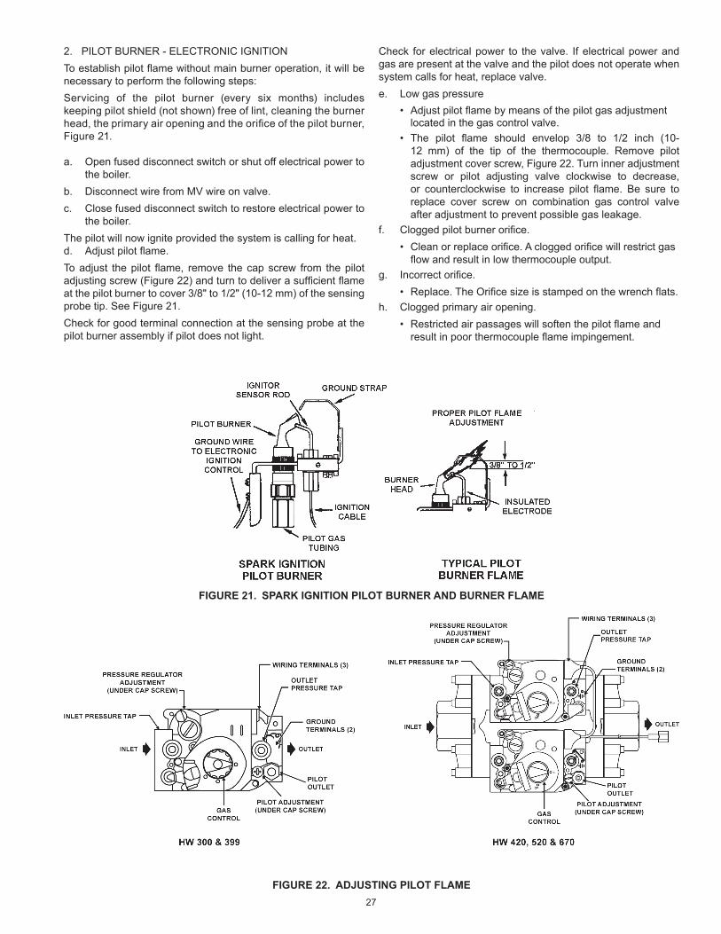
27
FIGURE 21. SPARK IGNITION PILOT BURNER AND BURNER FLAME
FIGURE 22. ADJUSTING PILOT FLAME
2. PILOT BURNER - ELECTRONIC IGNITIONTo establish pilot flame without main burner operation, it will be necessary to perform the following steps:Servicing of the pilot burner (every six months) includes keeping pilot shield (not shown) free of lint, cleaning the burner head, the primary air opening and the orifice of the pilot burner, Figure 21.
a. Open fused disconnect switch or shut off electrical power to the boiler.
b. Disconnect wire from MV wire on valve.c. Close fused disconnect switch to restore electrical power to
the boiler.The pilot will now ignite provided the system is calling for heat.d. Adjust pilot flame.To adjust the pilot flame, remove the cap screw from the pilot adjusting screw (Figure 22) and turn to deliver a sufficient flame at the pilot burner to cover 3/8" to 1/2" (10-12 mm) of the sensing probe tip. See Figure 21.Check for good terminal connection at the sensing probe at the pilot burner assembly if pilot does not light.
Check for electrical power to the valve. If electrical power and gas are present at the valve and the pilot does not operate when system calls for heat, replace valve.e. Low gas pressure
• Adjust pilot flame by means of the pilot gas adjustment located in the gas control valve.
• The pilot flame should envelop 3/8 to 1/2 inch (10-12 mm) of the tip of the thermocouple. Remove pilot adjustment cover screw, Figure 22. Turn inner adjustment screw or pilot adjusting valve clockwise to decrease, or counterclockwise to increase pilot flame. Be sure to replace cover screw on combination gas control valve after adjustment to prevent possible gas leakage.
f. Clogged pilot burner orifice.• Clean or replace orifice. A clogged orifice will restrict gas
flow and result in low thermocouple output.g. Incorrect orifice.
• Replace. The Orifice size is stamped on the wrench flats.h. Clogged primary air opening.
• Restricted air passages will soften the pilot flame and result in poor thermocouple flame impingement.

28
6. Remove the pressure gauge or manometer from the manifold pressure tapping. Replace the screw-in plug in the manifold pressure tap.
7. Repeat steps 7 thru 11 of the OPERATING INSTRUCTIONS on Page 31. The boiler will resume normal operation.
When the boiler is operating at full capacity, or full gas input, it should consume 1 cu. ft. of gas in approximately the time indicated in Table 16.
TYPE GAS
HEATING VALUE BTU/FT.
TIME TO CONSUME 1 CU. FT. OF GAS (SECONDS)
HW-300 HW-399 HW-420 HW-520 HW-670
Natural 1050 12.6 9.5 9.0 7.3 5.7
Propane 2500 30.0 22.6 21.4 17.3 13.4
Minor variances from input on rating plate can be corrected by adjustment of gas pressure regulators. Refer to Gas manifold pressure regulators on Page 25.The inlet gas pressure must not exceed or be less than the values shown on rating plate.
CHECKING AND ADJUSTING INPUT
1. Follow steps 1 thru 6 of the OPERATING INSTRUCTIONS on Page 31.
2. Attach a pressure gauge or a manometer to the manifold pressure tapping and refer to Table 16 for correct manifold pressure.
3. Follow steps 7 thru 11 of the OPERATING INSTRUCTIONS.4. Use this formula to “clock” the meter. Be sure that other gas
consuming appliances are not ON during this interval.
3600 x H = Btuh T
Btuh = The approximate actual input rate. T = Time in seconds to burn one cubic foot of gas. H = Heating value of the fuel gas in Btu per cubic foot of gas.
EXAMPLE:
T = 9.0 seconds/ft3
H = 1050 Btu/ft3(natural gas) Btuh = ?
Gas flow through meter:
3600 x 1050 = 420,000 Btuh 9.0
Small changes in the input rate may be made by adjusting the manifold pressure, refer to Gas manifold pressure regulators on Page 25. Under no circumstances should you exceed the maximum input rate for the boiler given in Table 3 on Page 7.
5. Repeat steps 1 thru 6 of the OPERATING INSTRUCTIONS.
TABLE 16. CONSUMPTION RATE (REFER TO OPERATING AT FULL INPUT OR FULL CAPACITY)
Breathing Hazard - Carbon Monoxide Gas
Breathing carbon monoxide can cause brain damage ordeath. Always read and understand instruction manual.
Under no circumstances shouldthe input exceed the rate shownon the boiler’s rating label.
Overfiring could result in damage tothe boiler’s and sooting.
Gas and carbon monoxide detectorsare available.
Fire and Explosion Hazard
Gas and carbon monoxide detectors areavailable.
Overfiring could result in fire orexplosion.
Under no circumstances should the input exceed the rate shown on the boiler’s rating label.

29
START
STAGE 1TRIAL FORIGNITION
STAGE 2MAIN BURNER
OPERATION
END
THERMOSTAT (CONTROLLER) CALLS FOR HEAT
SPARK GENERATOR POWEREDFirst valve (pilot) operator opens
PILOT BURNER OPERATIONPilot burner lights. Pilot burner does not lightModule senses Module Responseflame current. S-8600M After 15 sec. ignition shut-down. 5 minute time delay before re-try.
S-8600H After 15 sec. ignition system locks out must be manually reset.
FLAME CURRENT SENSED• Spark generator off.• Second valve operator (main) opens.
MAIN BURNER OPERATIONModule monitors pilot flame current.
THERMOSTAT (CONTROLLER) SATISFIEDValves close, pilot and main burners are off.
POWER INTERRUPTIONSystem shuts off, restartswhen power is restored.
PILOT FLAME FAILUREMain valve closes.Module starts trial forignition.

30
LIGHTING AND OPERATING INSTRUCTIONS (NATURAL AND PROPANE FOR HW300 - HW399)

31
LIGHTING AND OPERATING INSTRUCTIONS (NATURAL AND PROPANE WITH I.I.D. FOR HW420 & UP)

32
TABLE 17. CER-TEMP 80 RECOVERY SYSTEM CHECKOUT PROCEDURE
Before any extensive troubleshooting, perform the following:Ensure that:
• Voltage (120 vac) is supplied to the boiler.• System control (tank temperature control, thermostat,
etc.) is calling for boiler operation (call for heat).• Other contacts (switches) are closed (relay, low water
cutoff, flow switch, coil protector, pressure switch, etc.).• Gas supply pressure is within the maximum and minimum
operating ranges listed on the boiler rating plate/label.
• Voltage (24 vac) is supplied by transformer.• Boiler is wired according to wiring diagram.
Note: Cross wiring the 24 volt circuit of the relay will short the transformer.
• All wire terminals/connectors are firmly attached to valves, modules, switches, limit controls, etc.
• For Propane (LP) models only check for possible lockout condition of the ignition module.
Use this checkout for Cer-Temp 80 Recovery Systems. (For hot water supply application only)
CHECKOUT SEQUENCESYSTEM OPERATION
CAUSE REMEDYCORRECT INCORRECT
Set tank temperature control (thermostat) 20°F (10°C) below tank water temperature.
Circulating pump and burner shut off.
With thermal balancer, pump off delay of approximately 2 minutes.
Pump and burner remain on.
Tank temperature control (thermostat) defective. Replace.
System wiring is incorrect. Correct wiring.
Circulating pump on. Pump wired for continuous operation. Correct wiring.
Burner on.
Gas control valve stuck or defective.
Correct or replace valve.
System wiring is incorrect. Correct wiring.
Set tank temperature control (thermostat) 20°F (10°C) above tank water temperature.
Circulating pump and burner on.
Circulating pump on.
High limit control set too low.
Replace. (If problem proven to be at this control by applying jumper to terminals.)
High limit control differential too wide.
System wiring is incorrect. Correct wiring.
Coil protector switch has activated.
Remove control cover, depress reset button.
Gas control valve or wiring defective.
Check wiring. Repair or replace valve.
Circulating pump and burner off.
Power off or system wiring is incorrect.
Check power supply and wiring.
Tank temperature control (thermostat) defective. Replace.
Burner on. System wiring is incorrect. Correct wiring.
Boiler outlet temperature exceeds 210°F (100°C).
Circulating pump on. Circulating pump and burner on.
High limit control defective, or set too high (max. should be set at 200°F).
Replace.
Set tank temperature control (thermostat) for desired water temperature.
System maintains desired water temperature.
TROUBLESHOOTING

33
CHECKING HONEYWELL S-8600H OR S-8600MINTERMITTENT IGNITION CONTROLS
Turn off gas supply.
Is voltage (24 Vac) across the 24 V terminals on module during “Call for heat”?
Turn off power supply.
Is ignition cable firmly plugged into pilot assembly and module?
Is ground wire firmly attached to pilot assembly and GND terminal on module?
Ensure ground strap is the closest metal to the igniter/sensor rod (electrode) to prevent the spark from shorting out to other metal parts (pilot screen, pilot shield, etc.).
Ignition cable must not touch metal surfaces or current carrying wires.
Is there a 1/8” gap between ground strap and electrode?
Is the ceramic insulator surrounding the electrode cracked or broken?
Replace pilot burner assembly.
Replace ignition module.
Turn on gas supply.Turn on power supply.
Securely connect cableand/or ground wire.
Carefully bend downwardtop of ground strap
to achieve 1/8” spark gap.
Replace IgnitionModule.
YES
NOYES
YES
NO
NO
NO
Is voltage (24 Vac) across the PV & MV/PV terminals on“call for heat”?
YES
NONOTE: S-8600M will automatically reset every 5 minutes. S8600H pilot valve will be de-energized if module goes into lockout condition. Reset system by turning electrical power off or by turning system controller to off or down below "call for heat". Wait one minute, then turn system on.
YES
Are ignition cable and ground wire in good condition(not brittle, burnt or cracked)?
Replace pilot burner and/or ground wire.
YES
NO
NO SPARK AT PILOT BURNER
YES

34
CHECKING HONEYWELL S-8600H OR S-8600M INTERMITTENT IGNITION CONTROLS
SPARK AT PILOT BURNER BUT PILOT WILL NOT LIGHT
Ensure all manual shutoff valves are fully open; all filters are clean; all gas connections are gas tight; pilot tubing is not damaged, obstructed or kinked; and pilot orifice is unclogged. Check for air in gas line, purge (bleed) line if necessary.
Are the wires securely attached to the pilot operator on the gas control and to the PV & MV/PV terminals on the ignition module?
Install a pressure gauge in the pilot tubing line between the gas control and the pilot burner assembly. Ensure that the pilot adjustment screw (under cap) is adjusted to a position that will permit gas to flow.
Is pilot gas flowing during ignition attempt?
Turn off power supply.
Is ignition cable firmly plugged into pilot assembly and module?
Is ground wire firmly attached to pilot assembly and GND terminal on module?
Are ignition cable and ground wire in good condition (not brittle, burnt, or cracked)?
Ensure ground strap is the closest metal to the igniter/sensor rod (electrode) to prevent the spark from shorting out to other metal parts (pilot screen, pilot shield, etc.).
Ignition cable must not touch metal surfaces or current carrying wires.
Is there a 1/8” gap between ground strap and electrode?
Is ceramic insulator surrounding the electrode in good condition (not cracked or broken)?
Is there excessive draft conditions that may cause pilot burner ignition problems?
Correct draft problems in a manner that would ensure adequate combustion and ventilation air and proper pilot burner performance.
YES
YES
YES
YES
YES
YES
YES
NO
NO
NO
NO
NO
NO
NOAttach wires firmly.
Replace gas control valve.
Turn on power supply.
Securely connect cable and/or ground
wire.
Replace pilot burner and/or ground wire.
Carefully bend down-wards top of ground
strap to achieve1/8” spark gap.
Replace pilot burner.
Replace ignitionmodule.
YES
YES

35
CHECKING HONEYWELL S-8600H OR S-8600M INTERMITTENT IGNITION CONTROLS
PILOT BURNER LIGHTS BUT MAIN BURNER DOES NOT LIGHT
Does the pilot flame cover 3/8” to 1/2” of igniter/sensor rod?
Does spark stay on for more than 15 seconds after the pilot is “proven” (lit)?
Ensure the ground wire and ignition cable are separate from each other (prevents shortingout).
Are they in good condition (not brittle, burnt orcracked)?
Is the ceramic insulator surrounding the igniter/sensor rod in good condition(not broken or cracked)?
Is the igniter/sensor rod in good condition (not worn, corroded, sooted or damaged)?
Replace ignition module.
Correct the situation by consulting the installation or user’s manual on how to adjust pilot flame.
Is voltage (24 Vac) across terminalsMV & MV/PV?
Are the wires securely attached to the mainvalve operator on the gas control and to terminals MV & MV/PV on ignition module?
Replaceignitionmodule.
Replace main gas control valve.
Replace pilot burner and/or ground wire.
Replace pilot burner.
Clean rod or replace pilot burner if necessary.
Attachwiresfirmly.
YES
YES
YES
YES
YES
NO
NO
NO
NO
NO
NO
NO
YES
YES

36
CHECKING HONEYWELL S8600H OR S-8600M INTERMITTENT IGNITION CONTROLS
NO SPARK AT PILOT BURNER BUT PILOT WILL NOT LIGHT
Turn off gas supply.
Is there a good connection between terminals?
Is module securely attached to boiler for good ground connection?
Is voltage (24VAC) across transformer positive terminal and GND with "call for heat"?
Is voltage (24VAC) across ignition module terminals 24 Volt and GND on "call for heater"?
NOTE: (For Propane (LP) models only) Pilot Valve will be de-energized if module goes into lockout condition. Reset system by turning electrical power off or by turning system controller down below "call for heat". Wait one minute then turn system on.
Turn on gas supply and/or power supply.
Turn off power supply.
Is high voltage cable assembly firmly plugged into module?
Is pilot ground wire firmly attached to the pilot assembly and GND terminal on module?
Are high voltage cable and ground wire in good condition (not brittle, burnt or cracked)?
Make sure pilot flame spreader (hood) is the closest metal to the electrode to prevent the spark from shorting out to other metal parts (pilot screen, pilot shield, etc).
High voltage cable must not touch metal surfaces or current carrying wires.
Is there a 7/64" spark gap between the tip (edge) of the hood and electrode, and is the gap located in the pilot gas stream?
Is the ceramic insulator surrounding the electrode in good condition (not cracked or broken)?
Replace pilot burner assembly.
YES
YES
YES
YES
YES
YES
NO
NO
NO
NO
NOCheck the circuit providing24 VAC.
Replace ignition module.
Securely connect cableand/or ground wire.
Replace pilot burner and/or ground wire.
Carefully bend down-wards top of ground
strap to achieve1/8” spark gap.
Replace ignition module.
NOFix connection and/ortighten module to theboiler.
YES
NO

37
FIGURE 23. LOCATION OF LED'S
YELLOW LEDFLASH CODEA INDICATES RECOMMENDED
SERVICE ACTION
Heartbeat Normal Flame Signal not applicable
2
Weak Flame Signal-System will operate reliably but flame signal is less than desired.
NOTE: This indication may flash temporarily during or shortly after lightoff on some applications.
Perform routine maintenance to assure optimum flame signal.
1
Marginal Flame Signal (less than 1.1µA)-System may not operate reliably over time.
Service call recommended.
NOTE: This indication may flash temporarily during or shortly after lightoff on some applications.
Check gas supply, pilot burner, flame sense wiring, contamination of flame sensor, burner ground connection.
OFF
No Flame or Flame Signal below minimum threshold for system operation.
not applicable
AFlash Code Descriptions:• Heartbeat: Constant 1/2 second bright 1/2 second dim
cycles.• The flash code number signifies that the LED flashes X
times at 2Hz, remains off for two seconds, and then repeats the sequence.
TABLE 18. YELLOW LED FLAME CODESThe following procedures are provided as a general guide.Any module should be replaced if it does not perform properly on checkout or troubleshooting.In addition, replace any module if it is wet or looks like it has ever been wet.
LED STATUS AND TROUBLESHOOTINGThe control has two LEDs; one for flame sensing and one for system status:
• Flame LED (Yellow)Indicates flame presence and strength. Refer to Table 18.
• Status LED (Green)Indicates system operation status and error conditions. Refer to Table 19 and Table 20 on Pages 38 and 39 for status specific to each model.

38
GREEN LEDFLASH CODE
(X+Y)AINDICATES NEXT SYSTEM ACTION RECOMMENDED SERVICE
ACTION
OFF No "Call for Heat" not applicable noneFlash Fast Startup - Flame sense calibration not applicable noneHeartbeat Normal operation not applicable none
25 minute Retry Delay
• Pilot flame not detected during trial for ignition
Initiate new trial for ignition after retry delay completed.
If system fails to light on next trial for ignition check gas supply, pilot burner, spark and flame sense wiring, flame sensor contaminated or out of position, burner ground connection.
3 Recycle• Flame failed during run
Initiate new trial for ignition. Flash code will remain through the ignition trial until flame is proved.
If system fails to light on next trial for ignition, check gas supply, pilot burner, flame sense wiring, contamination of flame sensor, burner ground connection.
4 Flame sensed out of sequence
If situation self corrects within 10 seconds, control returns to normal sequence. If flame out of sequence remains longer than 10 seconds, control goes to Flash code 6+4 (see below).
Check for pilot flame. Replace gas control valve if pilot flame is present. If no pilot flame, cycle "Call for Heat." If error repeats, replace control.
7 Flame sense leakage to ground
Control remains in wait mode. When the fault corrects, control resumes normal operation after a one minute delay.
Check flame sense lead wire for damage or shorting. Check that flame sensor is in proper position.
Check flame sensor ceramic for cracks, damage or tracking.
8 Low secondary voltage supply-(below 15.5 Vac)
Control remains in wait mode. When the fault corrects, control resumes normal operation after a one minute delay.
Check transformer and AC line for proper input voltage to the control. Check with full system load on the transformer.
6+25 minute Retry Delay
• On every third retry on the same "Call for Heat"
Initiate new trial for ignition after retry delay completed.
Check gas supply line, pilot burner, spark and flame sense wiring, flame sensor contaminated or out of position, burner ground connection.
6+3 On every 6th flame failure during run on the same "Call for Heat"
5 minute retry delay, then initiate new trial for ignition.
Check gas supply, pilot burner, flame sense wiring, contamination of flame sensor, burner ground connection.
6+4 Flame sensed out of sequence-longer than 10 seconds
Control waits until flame is no longer sensed and then goes to soft lockout. Flash code continues. Control auto resets from soft lockout after one hour.
Check for pilot flame. Replace gas control valve if pilot flame present. If no pilot flame, cycle "Call for Heat." If error repeats, replace control.
ON Soft lockout due to error detected during self check sequences
Control auto resets from soft lockout after one hour.
Reset by cycling "Call for Heat." If error repeats, replace the control.
AFlash Code Descriptions:• Flash Fast: rapid blinking.• Heartbeat: Constant 1/2 second bright 1/2 second dim cycles.• A single flash code number signifies that the LED flashes X times at 2Hz, remains off for two seconds, and then repeats the
sequence.• X+Y flash codes signify that the LED flashes X times at 2Hz, remains off for two seconds, flashes Y times at 2Hz, remains off
for three seconds, and then repeats the sequence.
TABLE 19. CONTINUOUS RETRY MODELS C, M, E AND K ONLY - GREEN LED STATUS CODES

39
GREEN LEDFLASH CODE
(X+Y)AINDICATES NEXT SYSTEM ACTION RECOMMENDED SERVICE
ACTION
OFF No "Call for Heat" not applicable noneFlash Fast Startup - Flame sense calibration not applicable noneHeartbeat Normal operation not applicable none
3 Recycle• Flame failed during run
Initiate new trial for ignition. Flash code will remain through the ignition trial until flame is proved.
If system fails to light on next trial for ignition, check gas supply, pilot burner, flame sense wiring, contamination of flame sensor, burner ground connection.
4 Flame sensed out of sequence
If situation self corrects within 10 seconds, control returns to normal sequence. If flame out of sequence remains longer than 10 seconds, control goes to Flash code 6+4 (see below).
Check for pilot flame. Replace gas control valve if pilot flame is present. If no pilot flame, cycle "Call for Heat." If error repeats, replace control.
7 Flame sense leakage to ground
Control remains in wait mode. When the fault corrects, control resumes normal operation after a one minute delay.
Check flame sense lead wire for damage or shorting. Check that flame sensor is in proper position.
Check flame sensor ceramic for cracks, damage or tracking.
8 Low secondary voltage supply-(below 15.5 Vac)
Control remains in wait mode. When the fault corrects, control resumes normal operation after a one minute delay.
Check transformer and AC line for proper input voltage to the control. Check with full system load on the transformer.
6+2 Failed trial for ignition resulting in lockout
Remain in lockout until "Call for Heat" is cycled.
Check gas supply line, pilot burner, spark and flame sense wiring, flame sensor contaminated or out of position, burner ground connection.
6+3More than 5 flame failures during run on the same "Call for Heat" resulting in lockout
Remain in lockout until "Call for Heat" is cycled.
Check gas supply, pilot burner, flame sense wiring, contamination of flame sensor, burner ground connection.
6+4 Flame sensed out of sequence-longer than 10 seconds
Control waits until flame is no longer sensed and then goes to soft lockout. Flash code continues. Control auto resets from soft lockout after one hour.
Check for pilot flame. Replace gas control valve if pilot flame present. If no pilot flame, cycle "Call for Heat." If error repeats, replace control.
ON Soft lockout due to error detected during self check sequences
Control auto resets from soft lockout after one hour.
Reset by cycling "Call for Heat." If error repeats, replace the control.
AFlash Code Descriptions:• Flash Fast: rapid blinking.• Heartbeat: Constant 1/2 second bright 1/2 second dim cycles.• A single flash code number signifies that the LED flashes X times at 2Hz, remains off for two seconds, and then repeats the
sequence.• X+Y flash codes signify that the LED flashes X times at 2Hz, remains off for two seconds, flashes Y times at 2Hz, remains off
for three seconds, and then repeats the sequence.
TABLE 20. LOCKOUT MODELS B, H, D AND J ONLY - GREEN LED STATUS CODES

40
GENERAL MAINTENANCEThese boilers are designed to give many years of efficient and satisfactory service when properly operated and maintained. To assure continued good performance, the following recommendations are made.
The area around the boiler should be kept clean and free from lint and debris. Sweeping the floor around the boiler should be done carefully. This will reduce the dust and dirt which may enter the burner and pilot air passages, causing improper combustion and sooting.
The flow of combustion and ventilation air to the boiler must not be obstructed. The boiler area must be kept clear and free from combustible materials, gasoline, and other flammable vapors and liquids.
Any safety devices including low water cutoffs used in conjunction with this boiler should receive periodic (every six months) inspection to assure proper operation. A low water cutoff device of the float type should be flushed every six months. All pressure relief valves should be inspected and manually operated at least twice a year. More frequent inspections may be necessary depending on water conditions.
Periodic checks, at least twice a year, should be made for water and/or gas leaks.The boiler mounted gas and electrical controls have been designed to give both dependable service and long life. However, malfunction can occur, as with any piece of equipment. It is therefore recommended that all components be checked periodically by a qualified service technician for proper operation.
MANUAL RESET HIGH LIMIT SWITCH CONTINUITY TEST
Do not depress the switch reset button prior to testing. With the boiler being cold, disconnect the leads from the switch. With a multimeter place a probe on each side of the switch. If the meter reads zero the switch is good. If you receive an infinite or OL signal, the reason could be:
1. Switch contacts open.• Depress reset button on switch (switch cannot be reset
until water temperature in the boiler coils drop below 200°F). Meter should read zero.
2. Defective switch or bad leads.• With leads attached, depress the switch button. If the
meter does not read zero, the switch is defective and must be replaced.
PRESSURE RELIEF VALVE TEST
Burn hazard.
Hot water discharge.
Keep clear of PressureRelief Valve discharge outlet.
If after manually operating the valve, it fails to completely reset and continues to release water, turn off power to the boiler at the main disconnect switch or breaker. Close the cold water inlet to the boiler and follow the draining instructions in this manual to drain the boiler. Should the pressure relief valve need to be replaced, call the toll free phone number listed on the back of this manual for further technical assistance.
CLEANING AND FLUSHING INSTRUCTIONS
INTERNAL CONTAMINANTSThe hydronic system must be internally cleaned and flushed after a new or replacement boiler has been installed to remove contaminants that may have accumulated during installation. This is doubly important when a replacement boiler is installed into an existing system where stop leak or other boiler additives have been used.Failure to clean and flush the system can produce acid concentrations that become corrosive, cause gases to form that block water circulation or lead to formation of deposits on the boiler surfaces, any of which could result in damage to the system and circulating pump.All hot water heating systems should be completely flushed with a grease removing solution to assure trouble-tree operation.Pipe joint compounds, soldering paste, grease on tubing and pipe all tend to contaminate a system.Failure to flush contaminates from a system can cause solids to form on the inside of boiler heat exchangers, create excessive amounts of air and other gases to block circulation, foul various system accessories and even deteriorate circulation seals and impellers.It is recommended that after installation, the boiler and system when filled should include the proper percentage of cleaning solution related to approximate water volume of the system. Fire and circulate for about one hour and then flush clean with fresh water. Commercial grease removing solutions are available from your distributor.
HOT WATER SUPPLY BOILERS PREVENTIVE MAINTENANCEFor care of the HW water system please refer to the A. O. Smith Users Information Manual supplied with the boiler.
FIGURE 24. PRESSURE RELIEF VALVE TEST

41
VENTING MAINTENANCE
It is recommended that the heating surfaces and vent piping of the boiler be checked every six months for dust, deterioration and carbon deposits. Remove all soot or other obstructions from chimney and flue which will retard free draft. Replace any damaged or deteriorated parts of the venting system.Qualified servicers should follow this procedure when the boiler’s external heating surfaces and vent pipe need cleaning.
1. Turn off the electrical power (main manual gas shutoff and pilot valves, if applicable).
Allow boiler parts and vent to cool before disassembly.2. Remove the boiler draft diverter and vent pipe running to
the chimney.• Check parts and chimney for obstructions and clean as
necessary.3. Remove burner from boiler and other metal parts as required
to clean and vacuum the heat exchanger and combustion coils.• Refer to parts list supplied with this manual for
disassembly aid.4. Reinstall the parts removed in steps 2 and 3.
• Be sure the vent pipe has a minimum upward pitch of one quarter inch per foot of length (21 mm/m) and is sealed as necessary.
5. Restore electrical power and gas supply to boiler.• Place boiler in operation by following the lighting
instructions in this manual.• Check for gas leaks and proper boiler and vent
operation.

42
The electrical connections must be made so that the circulating pump will operate before the gas control valve opens. At no time may the controlling system allow the burner to fire when there is no water flow through the boilers.Refer to the diagram in Figure 25 on Pages 43 for proper wiring sequence with conventional single boiler installations.The thermal balancer shown is factory included by A. O. Smith. This device serves as a pump shutdown delay switch to balance the rising boiler water temperature to system temperature before the pump stops. Overshooting of boiler temperature is prevented and stack loss after shutdown is negligible.
If any of the original wire, as supplied with the boiler, must be replaced, it must be replaced with type 1050c wire or its equivalent, except for the flame sensor and ignition cable which are 250 0c and wires connected to the coil protector which are 2000c.
WIRINGWIRING CONNECTIONS
CONVENTIONAL INSTALLATIONSAll electrical work must be installed in accordance with current editions National Electrical Code, ANSI/NFPA 70 and/or the Canadian Electrical Code, PART 1, CSA C22.1, Electrical Code and must conform to local regulations.The boiler, when installed, must be electrically bonded to ground in accordance with the requirements of the authority having jurisdiction or, in the absence of such requirements, with the current editions National Electrical Code, ANSI/NFPA 70 and/or the Canadian Electrical Code Part 1, CSA C22.1, Electrical Code.Strict adherence to piping and wiring diagrams is required to prevent constant pump operation when system temperature control is satisfied. Otherwise the warranty is void as stipulated in the limited warranty on the instructions manual.
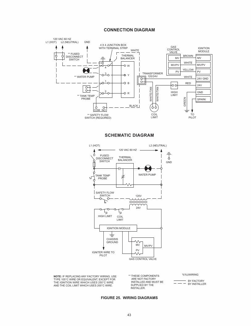
43
120 VAC 60 HZL1 (HOT) L2 (NEUTRAL)
)LARTUEN( 2L)TOH( 1L
120 VAC 60 HZ
120V
24V
HIGH LIMIT
IGNITION MODULE
CHASSISGROUND
IGNITER WIRE TOPILOT
NOTE: IF REPLACING ANY FACTORY WIRING, USETYPE 105°C WIRE OR EQUIVALENT, EXCEPT FORTHE IGNITION WIRE WHICH USES 250°C WIREAND THE COIL LIMIT WHICH USES 200°C WIRE.
%%UWIRING
BY FACTORYBY INSTALLER
** THESE COMPONENTS ARE NOT FACTORY INSTALLED AND MUST BE SUPPLIED BY THE INSTALLER.
GAS CONTROL VALVE
COILLIMIT
GND4 X 4 JUNCTION BOX
WITH TERMINAL STRIPWHITE
GASCONTROL
VALVEBROWN
IGNITIONMODULE
WHITE
YELLOW
WHITE
RED
MV MV
PV PV
24V GND
GND
GND
SPARK
TOPILOT
24V
MV/PV MV/PV
MV
PV
MV/PV
THERMALBALANCER
THERMALBALANCER
** FUSED DISCONNECT
SWITCH
FUSEDDISCONNECT
SWITCH
** TANK TEMPPROBE
TANK TEMPPROBE
WATER PUMP
** SAFETY FLOWSWITCH (REQUIRED)
SAFETY FLOWSWITCH
COILLIMIT
TRANSFORMER120/24V
HIGHLIMIT
WH
ITE
/TA
N
GR
EE
N
WH
ITE
/TA
N
** WATER PUMP
4 W
Y
B
R
3
1
2
COM NOBLACK
CONNECTION DIAGRAM
SCHEMATIC DIAGRAM
FIGURE 25. WIRING DIAGRAMS

44
FIGURE 26. CER - TEMP 80 - 1 UNIT INSTALLATION - FOR HOT WATER SUPPLY APPLICATION
FIGURE 27. SCHEMATIC: CER - TEMP 80 - 1 UNIT INSTALLATION - FOR HOT WATER SUPPLY APPLICATION
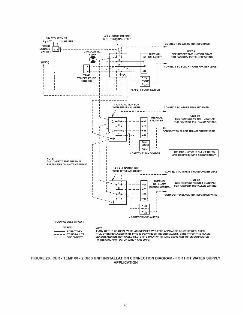
45
FIGURE 28. CER - TEMP 80 - 2 OR 3 UNIT INSTALLATION CONNECTION DIAGRAM - FOR HOT WATER SUPPLY APPLICATION

46
FIGURE 29. CER - TEMP 80 - 2 OR 3 UNIT INSTALLATION SCHEMATIC DIAGRAM - FOR HOT WATER SUPPLY APPLICATION

47
NO
TES
:1.
P
refe
rred
pip
ing
diag
ram
.2.
Th
e te
mpe
ratu
re a
nd p
ress
ure
relie
f val
ve s
ettin
g sh
all n
ot e
xcee
d pr
essu
re ra
ting
of a
ny c
ompo
nent
in th
e sy
stem
.3.
S
ervi
ce v
alve
s ar
e sh
own
for s
ervi
cing
uni
t. H
owev
er, l
ocal
cod
es s
hall
gove
rn th
eir u
sage
.4.
A
. O. S
mith
pip
ing
met
hod
is b
ased
on
50 e
quiv
alen
t fee
t of p
ipin
g. B
oile
r pla
cem
ent s
hall
be a
s cl
ose
as p
ract
ical
to th
e
stor
age
tank
. App
licat
ions
in e
xces
s of
thes
e re
com
men
datio
ns s
hall
requ
ire a
lice
nsed
eng
inee
r for
des
ign
assi
stan
ce.
BU
RK
AY H
W(3
00-6
70) -
ON
E T
EM
PE
RAT
UR
E-O
NE
BO
ILE
R/V
ER
TIC
AL
STO
RA
GE
TA
NK
R
EC
OV
ER
Y S
YS
TEM
LEG
EN
DTE
MP
ER
ATU
RE
& P
RE
SS
UR
ER
ELI
EF
VALV
E
PR
ES
SU
RE
RE
LIE
F VA
LVE
CIR
CU
LATI
NG
PU
MP
TAN
K TE
MPE
RAT
UR
E C
ON
TRO
L
DR
AIN
FULL
PO
RT
BA
LL V
ALV
E
TEM
PE
RAT
UR
E G
AG
E
WAT
ER
FLO
W S
WIT
CH
CH
EC
K V
ALV
EW
AR
NIN
G: T
HIS
DR
AWIN
G S
HO
WS
SU
GG
ES
TED
PIP
ING
CO
NFI
GU
RAT
ION
AN
D O
THE
R D
EV
ICE
S;
CH
EC
K W
ITH
LO
CA
L C
OD
ES
AN
D O
RD
INA
NC
ES
FOR
AD
DIT
ION
AL
RE
QU
IRE
ME
NTS
.
EX
PA
NS
ION
TAN
K
CO
LD W
ATE
RS
UP
PLY
SY
STE
MR
ETU
RN
AOSSTORAGE TANK
ALT
ER
NA
TE C
OLD
WA
TER
CO
NN
EC
TIO
NFO
R O
LD S
TYLE
TA
NK
HO
T W
ATE
RTO
FIX
TUR
ES
DE
-LIM
ING
TE
E
FIN
ISH
ED
FLO
OR
FIG
UR
E 30
. O
NE
TEM
PER
ATU
RE
- ON
E B
OIL
ER/ V
ERTI
CA
L ST
OR
AG
E TA
NK
REC
OVE
RY S
YSTE
M
PIPING DIAGRAMS

48
NO
TES:
1.
Pref
erre
d pi
ping
dia
gram
.2.
Th
e te
mpe
ratu
re a
nd p
ress
ure
relie
f val
ve s
ettin
g sh
all n
ot e
xcee
d pr
essu
re ra
ting
of a
ny c
ompo
nent
in th
e sy
stem
.3.
Se
rvic
e va
lves
are
sho
wn
for s
ervi
cing
uni
t. H
owev
er, l
ocal
cod
es s
hall
gove
rn th
eir u
sage
.4.
A.
O. S
mith
pip
ing
met
hod
is b
ased
on
50 e
quiv
alen
t fee
t of p
ipin
g. B
oile
r pla
cem
ent s
hall
be a
s cl
ose
as p
ract
ical
to th
e
stor
age
tank
. App
licat
ions
in e
xces
s of
thes
e re
com
men
datio
ns s
hall
requ
ire a
lice
nsed
eng
inee
r for
des
ign
assi
stan
ce.
BURK
AY H
W(3
00-6
70) -
ON
E TE
MPE
RAT
UR
E-O
NE
BOIL
ER/H
OR
IZO
NTA
L ST
OR
AGE
TAN
K R
ECO
VERY
SYS
TEM
LEG
END
TEM
PER
ATU
RE
& PR
ESSU
RE
REL
IEF
VALV
E
PRES
SUR
E R
ELIE
F VA
LVE
CIR
CU
LATI
NG
PU
MP
TANK
TEM
PERA
TURE
CO
NTRO
L
DR
AIN
FULL
PO
RT B
ALL
VALV
E
TEM
PER
ATU
RE
GAG
E
WAT
ER F
LOW
SW
ITC
H
CH
ECK
VALV
EW
ARN
ING
: TH
IS D
RAW
ING
SH
OW
S SU
GG
ESTE
DPI
PIN
G C
ON
FIG
UR
ATIO
N A
ND
OTH
ER D
EVIC
ES;
CH
ECK
WIT
H L
OC
AL C
OD
ES A
ND
OR
DIN
ANC
ESFO
R A
DD
ITIO
NAL
REQ
UIR
EMEN
TS.
EXPA
NSI
ON
TAN
K
CO
LD W
ATER
SUPP
LYAO
SST
OR
AGE
TAN
K
HO
T W
ATER
TO F
IXTU
RES
ALTE
RN
ATE
LOC
ATIO
N
SYST
EM R
ETU
RN
LOC
ATE
ELBO
W A
S C
LOSE
TO T
ANK
AS P
OSS
IBLE
DE-
LIM
ING
TEE
FIN
ISH
ED F
LOO
R
FIG
UR
E 31
. O
NE
TEM
PER
ATU
RE
- ON
E B
OIL
ER/ H
OR
IZO
NTA
L ST
OR
AG
E TA
NK
REC
OVE
RY S
YSTE
M

49
NO
TES:
1.
Pref
erre
d pi
ping
dia
gram
.2.
Th
e te
mpe
ratu
re a
nd p
ress
ure
relie
f val
ve s
ettin
g sh
all n
ot e
xcee
d pr
essu
re ra
ting
of a
ny c
ompo
nent
in th
e sy
stem
.3.
Se
rvic
e va
lves
are
sho
wn
for s
ervi
cing
uni
t. H
owev
er, l
ocal
cod
es s
hall
gove
rn th
eir u
sage
.4.
A.
O. S
mith
pip
ing
met
hod
is b
ased
on
50 e
quiv
alen
t fee
t of p
ipin
g. B
oile
r pla
cem
ent s
hall
be a
s cl
ose
as p
ract
ical
to th
e
stor
age
tank
. App
licat
ions
in e
xces
s of
thes
e re
com
men
datio
ns s
hall
requ
ire a
lice
nsed
eng
inee
r for
des
ign
assi
stan
ce.
BURK
AY H
W(3
00-6
70) -
ON
E TE
MPE
RAT
UR
E-TW
O B
OIL
ER/V
ERTI
CAL
STO
RAG
E TA
NK
REC
OVE
RY S
YSTE
M
LEG
END
TEM
PER
ATU
RE
& PR
ESSU
RE
REL
IEF
VALV
E
PRES
SUR
E R
ELIE
F VA
LVE
CIR
CU
LATI
NG
PU
MP
TANK
TEM
PERA
TURE
CO
NTRO
L
DR
AIN
FULL
PO
RT B
ALL
VALV
E
TEM
PER
ATU
RE
GAG
E
WAT
ER F
LOW
SW
ITC
H
CH
ECK
VALV
EW
ARN
ING
: TH
IS D
RAW
ING
SH
OW
S SU
GG
ESTE
DPI
PIN
G C
ON
FIG
UR
ATIO
N A
ND
OTH
ER D
EVIC
ES;
CH
ECK
WIT
H L
OC
AL C
OD
ES A
ND
OR
DIN
ANC
ESFO
R A
DD
ITIO
NAL
REQ
UIR
EMEN
TS.
EXPA
NSI
ON
TAN
K
CO
LD W
ATER
SUPP
LY
AOSSTORAGE TANK
ALTE
RN
ATE
CO
LD W
ATER
CO
NN
ECTI
ON
FOR
OLD
STY
LE T
ANK
HO
T W
ATER
TO F
IXTU
RES
SYST
EM R
ETU
RN
DE-
LIM
ING
TEE
DE-
LIM
ING
TEE
FIN
ISH
ED F
LOO
R
B
AB
BOIL
ERM
OD
EL (H
W)
BOIL
ERPI
PIN
G S
IZE
“A” (
INC
H)
MAN
IFO
LDPI
PIN
G S
IZE
“B” (
INC
H)
300
1 1/
42
399-
420
1 1/
22
520-
670
22
1/2
FIG
UR
E 32
. O
NE
TEM
PER
ATU
RE
- TW
O B
OIL
ERS/
VER
TIC
AL
STO
RA
GE
TAN
K R
ECO
VERY
SYS
TEM

50
NO
TES:
1.
Pref
erre
d pi
ping
dia
gram
.2.
Th
e te
mpe
ratu
re a
nd p
ress
ure
relie
f val
ve s
ettin
g sh
all n
ot e
xcee
d pr
essu
re ra
ting
of a
ny c
ompo
nent
in th
e sy
stem
.3.
Se
rvic
e va
lves
are
sho
wn
for s
ervi
cing
uni
t. H
owev
er, l
ocal
cod
es s
hall
gove
rn th
eir u
sage
.4.
A.
O. S
mith
pip
ing
met
hod
is b
ased
on
50 e
quiv
alen
t fee
t of p
ipin
g. B
oile
r pla
cem
ent s
hall
be a
s cl
ose
as p
ract
ical
to th
e
stor
age
tank
. App
licat
ions
in e
xces
s of
thes
e re
com
men
datio
ns s
hall
requ
ire a
lice
nsed
eng
inee
r for
des
ign
assi
stan
ce.
BURK
AY H
W(3
00-6
70) -
ON
E TE
MPE
RAT
UR
E-TW
O B
OIL
ER/H
OR
IZO
NTA
L ST
OR
AGE
TAN
K R
ECO
VERY
SYS
TEM
LEG
END
TEM
PER
ATU
RE
& PR
ESSU
RE
REL
IEF
VALV
E
PRES
SUR
E R
ELIE
F VA
LVE
CIR
CU
LATI
NG
PU
MP
TANK
TEM
PERA
TURE
CO
NTRO
L
DR
AIN
FULL
PO
RT B
ALL
VALV
E
TEM
PER
ATU
RE
GAG
E
WAT
ER F
LOW
SW
ITC
H
CH
ECK
VALV
EW
ARN
ING
: TH
IS D
RAW
ING
SH
OW
S SU
GG
ESTE
DPI
PIN
G C
ON
FIG
UR
ATIO
N A
ND
OTH
ER D
EVIC
ES;
CH
ECK
WIT
H L
OC
AL C
OD
ES A
ND
OR
DIN
ANC
ESFO
R A
DD
ITIO
NAL
REQ
UIR
EMEN
TS.
EXPA
NSI
ON
TAN
K
CO
LD W
ATER
SUPP
LY
AOS
STO
RAG
E TA
NK
HO
T W
ATER
TO F
IXTU
RES
ALTE
RN
ATE
LOC
ATIO
N
SED
IMEN
T R
ISER
SYST
EMR
ETU
RN
DE-
LIM
ING
TEE
DE-
LIM
ING
TEE
FIN
ISH
ED F
LOO
RB
AB
A
BOIL
ERM
OD
EL (H
W)
BOIL
ERPI
PIN
G S
IZE
“A” (
INC
H)
MAN
IFO
LDPI
PIN
G S
IZE
“B” (
INC
H)
300
1 1/
42
399-
420
1 1/
22
520-
670
22
1/2
FIG
UR
E 33
. O
NE
TEM
PER
ATU
RE
- TW
O B
OIL
ERS/
HO
RIZ
ON
TAL
STO
RA
GE
TAN
K R
ECO
VERY
SYS
TEM

51
NO
TES:
1.
Pref
erre
d pi
ping
dia
gram
.2.
Th
e te
mpe
ratu
re a
nd p
ress
ure
relie
f val
ve s
ettin
g sh
all n
ot e
xcee
d pr
essu
re ra
ting
of a
ny c
ompo
nent
in th
e sy
stem
.3.
Se
rvic
e va
lves
are
sho
wn
for s
ervi
cing
uni
t. H
owev
er, l
ocal
cod
es s
hall
gove
rn th
eir u
sage
.4.
A.
O. S
mith
pip
ing
met
hod
is b
ased
on
50 e
quiv
alen
t fee
t of p
ipin
g. B
oile
r pla
cem
ent s
hall
be a
s cl
ose
as p
ract
ical
to th
e
stor
age
tank
. App
licat
ions
in e
xces
s of
thes
e re
com
men
datio
ns s
hall
requ
ire a
lice
nsed
eng
inee
r for
des
ign
assi
stan
ce.
BURK
AY H
W(3
00-6
70) -
ON
E TE
MPE
RAT
UR
E-TH
REE
BO
ILER
/VER
TIC
AL S
TOR
AGE
TAN
K R
ECO
VERY
SYS
TEM
LEG
END
TEM
PER
ATU
RE
& PR
ESSU
RE
REL
IEF
VALV
E
PRES
SUR
E R
ELIE
F VA
LVE
CIR
CU
LATI
NG
PU
MP
TANK
TEM
PERA
TURE
CO
NTRO
L
DR
AIN
FULL
PO
RT B
ALL
VALV
E
TEM
PER
ATU
RE
GAG
E
WAT
ER F
LOW
SW
ITC
H
CH
ECK
VALV
EW
ARN
ING
: TH
IS D
RAW
ING
SH
OW
S SU
GG
ESTE
DPI
PIN
G C
ON
FIG
UR
ATIO
N A
ND
OTH
ER D
EVIC
ES;
CH
ECK
WIT
H L
OC
AL C
OD
ES A
ND
OR
DIN
ANC
ESFO
R A
DD
ITIO
NAL
REQ
UIR
EMEN
TS.
EXPA
NSI
ON
TAN
K
CO
LD W
ATER
SUPP
LY
AOSSTORAGE TANK
ALTE
RN
ATE
CO
LD W
ATER
CO
NN
ECTI
ON
FOR
OLD
STY
LE T
ANK
HO
T W
ATER
TO F
IXTU
RES
SYST
EM R
ETU
RN
DE-
LIM
ING
TEE
FIN
ISH
ED F
LOO
R
B
AB
AA
B
BOIL
ERM
OD
EL (H
W)
BOIL
ERPI
PIN
G S
IZE
“A” (
INC
H)
MAN
IFO
LDPI
PIN
G S
IZE
“B” (
INC
H)
300
1 1/
42
399-
420
1 1/
22
1/2
520-
670
23
FIG
UR
E 34
. O
NE
TEM
PER
ATU
RE
- TH
REE
BO
ILER
S/ V
ERTI
CA
L ST
OR
AG
E TA
NK
REC
OVE
RY S
YSTE
M

52
NO
TES:
1.
Pref
erre
d pi
ping
dia
gram
.2.
Th
e te
mpe
ratu
re a
nd p
ress
ure
relie
f val
ve s
ettin
g sh
all n
ot e
xcee
d pr
essu
re ra
ting
of a
ny c
ompo
nent
in th
e sy
stem
.3.
Se
rvic
e va
lves
are
sho
wn
for s
ervi
cing
uni
t. H
owev
er, l
ocal
cod
es s
hall
gove
rn th
eir u
sage
.4.
A.
O. S
mith
pip
ing
met
hod
is b
ased
on
50 e
quiv
alen
t fee
t of p
ipin
g. B
oile
r pla
cem
ent s
hall
be a
s cl
ose
as p
ract
ical
to th
e
stor
age
tank
. App
licat
ions
in e
xces
s of
thes
e re
com
men
datio
ns s
hall
requ
ire a
lice
nsed
eng
inee
r for
des
ign
assi
stan
ce.
BURK
AY H
W(3
00-6
70) -
ON
E TE
MPE
RAT
UR
E-TH
REE
BO
ILER
/HO
RIZ
ON
TAL
STO
RAG
E TA
NK
REC
OVE
RY S
YSTE
M
LEG
END
TEM
PER
ATU
RE
& PR
ESSU
RE
REL
IEF
VALV
E
PRES
SUR
E R
ELIE
F VA
LVE
CIR
CU
LATI
NG
PU
MP
TANK
TEM
PERA
TURE
CO
NTRO
L
DR
AIN
FULL
PO
RT B
ALL
VALV
E
TEM
PER
ATU
RE
GAG
E
WAT
ER F
LOW
SW
ITC
H
CH
ECK
VALV
EW
ARN
ING
: TH
IS D
RAW
ING
SH
OW
S SU
GG
ESTE
DPI
PIN
G C
ON
FIG
UR
ATIO
N A
ND
OTH
ER D
EVIC
ES;
CH
ECK
WIT
H L
OC
AL C
OD
ES A
ND
OR
DIN
ANC
ESFO
R A
DD
ITIO
NAL
REQ
UIR
EMEN
TS.
EXPA
NSI
ON
TAN
K
CO
LD W
ATER
SUPP
LY
AOS
STO
RAG
E TA
NK
HO
T W
ATER
TO F
IXTU
RES
SED
IMEN
T R
ISER
ALTE
RN
ATE
LOC
ATIO
N
SYST
EM R
ETU
RN
DE-
LIM
ING
TEE
FIN
ISH
ED F
LOO
R
B
AA
AB
BOIL
ERM
OD
EL (H
W)
BOIL
ERPI
PIN
G S
IZE
“A” (
INC
H)
MAN
IFO
LDPI
PIN
G S
IZE
“B” (
INC
H)
300
1 1/
42
399-
420
1 1/
22
1/2
520-
670
23
FIG
UR
E 35
. O
NE
TEM
PER
ATU
RE
- TH
REE
BO
ILER
S/ H
OR
IZO
NTA
L ST
OR
AG
E TA
NK
REC
OVE
RY S
YSTE
M

53
NO
TES
:1.
P
refe
rred
pip
ing
layo
ut.
2.
The
tem
pera
ture
and
pre
ssur
e re
lief v
alve
set
ting
shal
l not
exc
eed
pres
sure
ratin
g of
any
com
pone
nt in
the
syst
em.
3.
Ser
vice
val
ves
are
show
n fo
r ser
vici
ng b
oile
r. H
owev
er, l
ocal
cod
es s
hall
gove
rn th
eir u
sage
.
HW
BU
RK
AY B
OIL
ER
(30
0-67
0) -
ON
E B
OIL
ER
PR
IMA
RY
/SE
CO
ND
AR
Y H
YD
RO
NIC
PIP
ING
SY
STE
M
LEG
EN
DTE
MP
ER
ATU
RE
& P
RE
SS
UR
ER
ELI
EF
VALV
E
PR
ES
SU
RE
RE
LIE
F VA
LVE
CIR
CU
LATI
NG
PU
MP
TEM
PER
ATU
RE
CO
NTR
OL
PRO
BE
DR
AIN
FULL
PO
RT
BA
LL V
ALV
E
TEM
PE
RAT
UR
E G
AG
E
WAT
ER
FLO
W S
WIT
CH
CH
EC
K V
ALV
E
CA
UTI
ON
: TH
IS D
RAW
ING
SH
OW
S S
UG
GE
STE
DP
IPIN
G C
ON
FIG
UR
ATIO
N A
ND
OTH
ER
DE
VIC
ES
;C
HE
CK
WIT
H L
OC
AL
CO
DE
S A
ND
OR
DIN
AN
CE
SFO
R A
DD
ITIO
NA
L R
EQ
UIR
EM
EN
TS.
HW
BO
ILER
BO
ILER
PIP
ING
SI
ZE “
A”
(INC
H)
MA
NIF
OLD
PIPI
NG
SIZ
E “B
” (IN
CH
)
300
1.25
”N
A
399-
420
1.50
”N
A
520-
670
2.00
”N
A
EX
PAN
SIO
N T
AN
K
MA
KE
-UP
WAT
ER
AIR
SE
PAR
ATO
R
SY
STE
M S
UP
PLY
SY
STE
M P
UM
P
SY
STE
M R
ETU
RN
PLA
CE
S T
EE
S A
S C
LOS
ETO
GE
THE
R A
S P
RA
CTI
CA
L
LOO
P TE
MP
ER
ATU
RE
PR
OB
E FIN
ISH
ED
FLO
OR
FIG
UR
E 36
. O
NE
BO
ILER
PR
IMA
RY/ S
ECO
ND
ARY
HYD
RO
NIC
PIP
ING
SYS
TEM

54
FIG
UR
E 37
. TW
O B
OIL
ERS
PRIM
ARY
/ SEC
ON
DA
RY H
YDR
ON
IC P
IPIN
G S
YSTE
M
NO
TES:
1.
Pref
erre
d pi
ping
layo
ut.
2.
The
tem
pera
ture
and
pre
ssur
e re
lief v
alve
set
ting
shal
l not
exc
eed
pres
sure
ratin
g of
any
com
pone
nt in
the
syst
em.
3.
Serv
ice
valv
es a
re s
how
n fo
r ser
vici
ng b
oile
r. H
owev
er, l
ocal
cod
es s
hall
gove
rn th
eir u
sage
.
HW
BU
RK
AY B
OIL
ER
S (
300-
670)
- TW
O B
OIL
ERS
PRIM
ARY/
SEC
ON
DAR
Y H
YDR
ON
IC P
IPIN
G S
YSTE
M
LEG
END
TEM
PER
ATU
RE
& PR
ESSU
RE
REL
IEF
VALV
E
PRES
SUR
E R
ELIE
F VA
LVE
CIR
CU
LATI
NG
PU
MP
TEM
PER
ATU
RE
CO
NTR
OL
PRO
BE
DR
AIN
FULL
PO
RT
BALL
VAL
VE
TEM
PER
ATU
RE
GAG
E
WAT
ER F
LOW
SW
ITC
H
CH
ECK
VALV
E
CAU
TIO
N: T
HIS
DR
AWIN
G S
HO
WS
SUG
GES
TED
PIPI
NG
CO
NFI
GU
RAT
ION
AN
D O
THER
DEV
ICES
;C
HEC
K W
ITH
LO
CAL
CO
DES
AN
D O
RD
INAN
CES
FOR
AD
DIT
ION
AL R
EQU
IREM
ENTS
.
HW
BO
ILER
BO
ILER
PIP
ING
SI
ZE “
A”
(INC
H)
MA
NIF
OLD
PIPI
NG
SIZ
E “B
” (IN
CH
)
300
1.25
”2.
00”
399-
420
1.50
”2.
00”
520-
670
2.00
”2.
50”
EXPA
NSI
ON
TAN
K
MAK
E-U
P W
ATER
AIR
SEP
ARAT
OR
SYST
EM S
UPP
LY
SYST
EM P
UM
P
SYST
EM R
ETU
RN
PLAC
ES T
EES
AS C
LOSE
TOG
ETH
ER A
S PR
ACTI
CAL
LOO
P TE
MPE
RAT
UR
E PR
OBE
FIN
ISH
ED F
LOO
R
A
B
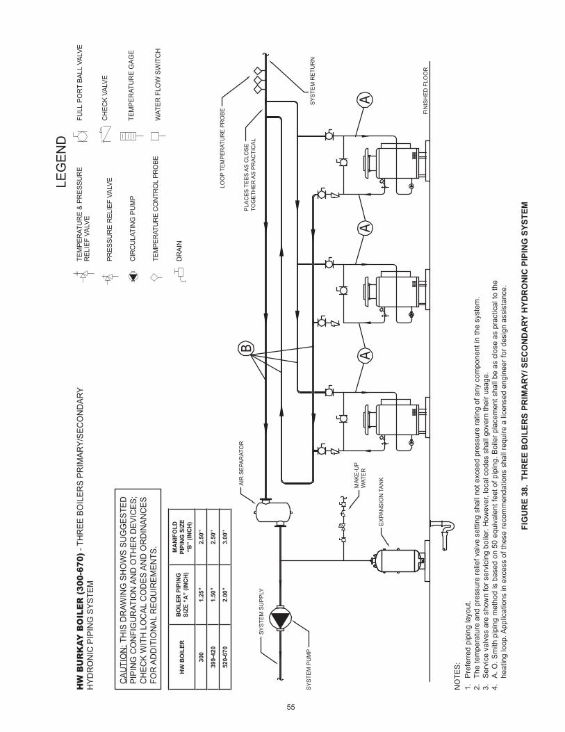
55
FIG
UR
E 38
. TH
REE
BO
ILER
S PR
IMA
RY/ S
ECO
ND
ARY
HYD
RO
NIC
PIP
ING
SYS
TEM
NO
TES:
1.
Pref
erre
d pi
ping
layo
ut.
2.
The
tem
pera
ture
and
pre
ssur
e re
lief v
alve
set
ting
shal
l not
exc
eed
pres
sure
ratin
g of
any
com
pone
nt in
the
syst
em.
3.
Serv
ice
valv
es a
re s
how
n fo
r ser
vici
ng b
oile
r. H
owev
er, l
ocal
cod
es s
hall
gove
rn th
eir u
sage
.4.
A.
O. S
mith
pip
ing
met
hod
is b
ased
on
50 e
quiv
alen
t fee
t of p
ipin
g. B
oile
r pla
cem
ent s
hall
be a
s cl
ose
as p
ract
ical
to th
e he
atin
g lo
op. A
pplic
atio
ns in
exc
ess
of th
ese
reco
mm
enda
tions
sha
ll re
quire
a li
cens
ed e
ngin
eer f
or d
esig
n as
sist
ance
.
HW
BU
RK
AY B
OIL
ER
(30
0-67
0) -
THR
EE B
OIL
ERS
PRIM
ARY/
SEC
ON
DAR
Y H
YDR
ON
IC P
IPIN
G S
YSTE
M
LEG
END
TEM
PER
ATU
RE
& PR
ESSU
RE
REL
IEF
VALV
E
PRES
SUR
E R
ELIE
F VA
LVE
CIR
CU
LATI
NG
PU
MP
TEM
PER
ATU
RE
CO
NTR
OL
PRO
BE
DR
AIN
FULL
PO
RT
BALL
VAL
VE
TEM
PER
ATU
RE
GAG
E
WAT
ER F
LOW
SW
ITC
H
CH
ECK
VALV
E
CAU
TIO
N: T
HIS
DR
AWIN
G S
HO
WS
SUG
GES
TED
PIPI
NG
CO
NFI
GU
RAT
ION
AN
D O
THER
DEV
ICES
;C
HEC
K W
ITH
LO
CAL
CO
DES
AN
D O
RD
INAN
CES
FOR
AD
DIT
ION
AL R
EQU
IREM
ENTS
.
HW
BO
ILER
BO
ILER
PIP
ING
SI
ZE “
A”
(INC
H)
MA
NIF
OLD
PIPI
NG
SIZ
E “B
” (IN
CH
)
300
1.25
”2.
50”
399-
420
1.50
”2.
50”
520-
670
2.00
”3.
00”
AA
A
B
EXPA
NSI
ON
TAN
K
MAK
E-U
PW
ATER
AIR
SEP
ARAT
OR
SYST
EM S
UPP
LY
SYST
EM P
UM
PSY
STEM
RET
UR
N
PLAC
ES T
EES
AS C
LOSE
TOG
ETH
ER A
S PR
ACTI
CAL
LOO
P TE
MPE
RAT
UR
E PR
OBE FI
NIS
HED
FLO
OR

56
FIG
UR
E 39
. FO
UR
BO
ILER
S PR
IMA
RY/ S
ECO
ND
ARY
HYD
RO
NIC
PIP
ING
SYS
TEM
NO
TES:
1.
Pref
erre
d pi
ping
layo
ut.
2.
The
tem
pera
ture
and
pre
ssur
e re
lief v
alve
set
ting
shal
l not
exc
eed
pres
sure
ratin
g of
any
com
pone
nt in
the
syst
em.
3.
Serv
ice
valv
es a
re s
how
n fo
r ser
vici
ng b
oile
r. H
owev
er, l
ocal
cod
es s
hall
gove
rn th
eir u
sage
.4.
A.
O. S
mith
pip
ing
met
hod
is b
ased
on
50 e
quiv
alen
t fee
t of p
ipin
g. B
oile
r pla
cem
ent s
hall
be a
s cl
ose
as p
ract
ical
to th
e he
atin
g lo
op. A
pplic
atio
ns in
exc
ess
of th
ese
reco
mm
enda
tions
sha
ll re
quire
a li
cens
ed e
ngin
eer f
or d
esig
n as
sist
ance
.
HW
BU
RK
AY B
OIL
ER
(30
0-67
0) -
FOU
R B
OIL
ERS
PRIM
ARY/
SEC
ON
DAR
Y H
YDR
ON
IC P
IPIN
G S
YSTE
M
LEG
END
TEM
PER
ATU
RE
& PR
ESSU
RE
REL
IEF
VALV
E
PRES
SUR
E R
ELIE
F VA
LVE
CIR
CU
LATI
NG
PU
MP
TEM
PER
ATU
RE
CO
NTR
OL
PRO
BE
DR
AIN
FULL
PO
RT
BALL
VAL
VE
TEM
PER
ATU
RE
GAG
E
WAT
ER F
LOW
SW
ITC
H
CH
ECK
VALV
E
CAU
TIO
N: T
HIS
DR
AWIN
G S
HO
WS
SUG
GES
TED
PIPI
NG
CO
NFI
GU
RAT
ION
AN
D O
THER
DEV
ICES
;C
HEC
K W
ITH
LO
CAL
CO
DES
AN
D O
RD
INAN
CES
FOR
AD
DIT
ION
AL R
EQU
IREM
ENTS
.
HW
BO
ILER
BO
ILER
PIP
ING
SI
ZE “
A”
(INC
H)
MA
NIF
OLD
PIPI
NG
SIZ
E “B
” (IN
CH
)
300
1.25
”2.
50”
399-
420
1.50
”3.
00”
520-
670
2.00
”4.
00”
AA
A
B
EXPA
NSI
ON
TAN
K
MAK
E-U
PW
ATER
AIR
SEP
ARAT
OR
SYST
EM S
UPP
LY
SYST
EM P
UM
PSY
STEM
RET
UR
N
PLAC
ES T
EES
AS C
LOSE
TOG
ETH
ER A
S PR
ACTI
CAL
LOO
P TE
MPE
RAT
UR
E PR
OBE
FIN
ISH
ED F
LOO
R

57
FIG
UR
E 40
. ZO
NE
PUM
PIN
G/ H
OR
IZO
NTA
L B
UFF
ER T
AN
K H
EATI
NG
SYS
TEM
EXPA
NSI
ON
TAN
K
MAK
E-U
P W
ATER
ZON
E PU
MPS
ZON
E LO
OP
SUPP
LIES
ZON
E R
ETU
RN
S
AIR
SEP
ARAT
OR
THER
MAL
ACC
UM
ULA
TOR
(BU
FFER
TAN
K)
FIN
ISH
ED F
LOO
R
AOS
STO
RAG
E TA
NK
NO
TES:
1.
Pref
erre
d pi
ping
layo
ut.
2.
The
tem
pera
ture
and
pre
ssur
e re
lief v
alve
set
ting
shal
l not
exc
eed
pres
sure
ratin
g of
any
com
pone
nt in
the
syst
em.
3.
Serv
ice
valv
es a
re s
how
n fo
r ser
vici
ng b
oile
r. H
owev
er, l
ocal
cod
es s
hall
gove
rn th
eir u
sage
.
HW
BU
RK
AY B
OIL
ER
(30
0-67
0) -
ZON
E PU
MPI
NG
/HO
RIZ
ON
TAL
BUFF
ER T
ANK
HEA
TIN
G S
YSTE
M
LEG
END
TEM
PER
ATU
RE
& PR
ESSU
RE
REL
IEF
VALV
E
PRES
SUR
E R
ELIE
F VA
LVE
CIR
CU
LATI
NG
PU
MP
TEM
PER
ATU
RE
CO
NTR
OL
PRO
BE
DR
AIN
FULL
PO
RT
BALL
VAL
VE
TEM
PER
ATU
RE
GAG
E
WAT
ER F
LOW
SW
ITC
H
CH
ECK
VALV
E
CAU
TIO
N: T
HIS
DR
AWIN
G S
HO
WS
SUG
GES
TED
PIPI
NG
CO
NFI
GU
RAT
ION
AN
D O
THER
DEV
ICES
;C
HEC
K W
ITH
LO
CAL
CO
DES
AN
D O
RD
INAN
CES
FOR
AD
DIT
ION
AL R
EQU
IREM
ENTS
.
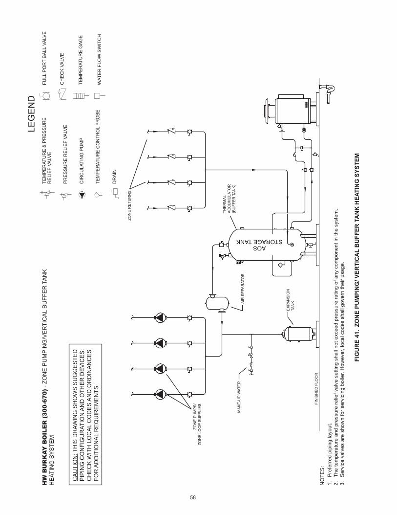
58
FIG
UR
E 41
. ZO
NE
PUM
PIN
G/ V
ERTI
CA
L B
UFF
ER T
AN
K H
EATI
NG
SYS
TEM
NO
TES:
1.
Pref
erre
d pi
ping
layo
ut.
2.
The
tem
pera
ture
and
pre
ssur
e re
lief v
alve
set
ting
shal
l not
exc
eed
pres
sure
ratin
g of
any
com
pone
nt in
the
syst
em.
3.
Serv
ice
valv
es a
re s
how
n fo
r ser
vici
ng b
oile
r. H
owev
er, l
ocal
cod
es s
hall
gove
rn th
eir u
sage
.
HW
BU
RK
AY B
OIL
ER
(30
0-67
0) -
ZON
E PU
MPI
NG
/VER
TIC
AL B
UFF
ER T
ANK
HEA
TIN
G S
YSTE
M
LEG
END
TEM
PER
ATU
RE
& PR
ESSU
RE
REL
IEF
VALV
E
PRES
SUR
E R
ELIE
F VA
LVE
CIR
CU
LATI
NG
PU
MP
TEM
PER
ATU
RE
CO
NTR
OL
PRO
BE
DR
AIN
FULL
PO
RT
BALL
VAL
VE
TEM
PER
ATU
RE
GAG
E
WAT
ER F
LOW
SW
ITC
H
CH
ECK
VALV
E
CAU
TIO
N: T
HIS
DR
AWIN
G S
HO
WS
SUG
GES
TED
PIPI
NG
CO
NFI
GU
RAT
ION
AN
D O
THER
DEV
ICES
;C
HEC
K W
ITH
LO
CAL
CO
DES
AN
D O
RD
INAN
CES
FOR
AD
DIT
ION
AL R
EQU
IREM
ENTS
.
EXPA
NSI
ON
TAN
K
THER
MAL
ACC
UM
ULA
TOR
(BU
FFER
TAN
K)M
AKE-
UP
WAT
ER
ZON
E R
ETU
RN
S
AIR
SEP
ARAT
OR
FIN
ISH
ED F
LOO
R
ZON
E PU
MPS
/ZO
NE
LOO
P SU
PPLI
ES
AOSSTORAGE TANK

59
FIG
UR
E 42
. B
OIL
ER/ V
ERTI
CA
L B
UFF
ER T
AN
K H
EATI
NG
SYS
TEM
NO
TES:
1.
Pref
erre
d pi
ping
layo
ut.
2.
The
tem
pera
ture
and
pre
ssur
e re
lief v
alve
set
ting
shal
l not
exc
eed
pres
sure
ratin
g of
any
com
pone
nt in
the
syst
em.
3.
Serv
ice
valv
es a
re s
how
n fo
r ser
vici
ng b
oile
r. H
owev
er, l
ocal
cod
es s
hall
gove
rn th
eir u
sage
.
HW
BU
RK
AY B
OIL
ER
(30
0-67
0) -
BOIL
ER/V
ERTI
CAL
BU
FFER
TAN
K H
EATI
NG
SY
STEM
LEG
END
TEM
PER
ATU
RE
& PR
ESSU
RE
REL
IEF
VALV
E
PRES
SUR
E R
ELIE
F VA
LVE
CIR
CU
LATI
NG
PU
MP
TEM
PER
ATU
RE
CO
NTR
OL
PRO
BE
DR
AIN
FULL
PO
RT
BALL
VAL
VE
TEM
PER
ATU
RE
GAG
E
WAT
ER F
LOW
SW
ITC
H
CH
ECK
VALV
E
CAU
TIO
N: T
HIS
DR
AWIN
G S
HO
WS
SUG
GES
TED
PIPI
NG
CO
NFI
GU
RAT
ION
AN
D O
THER
DEV
ICES
;C
HEC
K W
ITH
LO
CAL
CO
DES
AN
D O
RD
INAN
CES
FOR
AD
DIT
ION
AL R
EQU
IREM
ENTS
.
EXPA
NSI
ON
TAN
K
MAK
E-U
P W
ATER
AIR
SEP
ARAT
OR
SYST
EM S
UPP
LY
SYST
EM P
UM
P
SYST
EM R
ETU
RN
FIN
ISH
ED F
LOO
R
AOSSTORAGE TANK

60
FIG
UR
E 43
. B
OIL
ER/ V
ERTI
CA
L B
UFF
ER T
AN
K, 3
WAY
MIX
ING
VA
LVE
HEA
TIN
G S
YSTE
M
NO
TES:
1.
Pref
erre
d pi
ping
layo
ut.
2.
The
tem
pera
ture
and
pre
ssur
e re
lief v
alve
set
ting
shal
l not
exc
eed
pres
sure
ratin
g of
any
com
pone
nt in
the
syst
em.
3.
Serv
ice
valv
es a
re s
how
n fo
r ser
vici
ng b
oile
r. H
owev
er, l
ocal
cod
es s
hall
gove
rn th
eir u
sage
.
HW
BU
RK
AY B
OIL
ER
(30
0-67
0) -
BOIL
ER/V
ERTI
CAL
BU
FFER
TAN
K, 3
-WAY
M
IXIN
G V
ALVE
HEA
TIN
G S
YSTE
M
LEG
END
TEM
PER
ATU
RE
& PR
ESSU
RE
REL
IEF
VALV
E
PRES
SUR
E R
ELIE
F VA
LVE
CIR
CU
LATI
NG
PU
MP
TEM
PER
ATU
RE
CO
NTR
OL
PRO
BE
DR
AIN
FULL
PO
RT
BALL
VAL
VE
TEM
PER
ATU
RE
GAG
E
WAT
ER F
LOW
SW
ITC
H
CH
ECK
VALV
E
CAU
TIO
N: T
HIS
DR
AWIN
G S
HO
WS
SUG
GES
TED
PIPI
NG
CO
NFI
GU
RAT
ION
AN
D O
THER
DEV
ICES
;C
HEC
K W
ITH
LO
CAL
CO
DES
AN
D O
RD
INAN
CES
FOR
AD
DIT
ION
AL R
EQU
IREM
ENTS
.
EXPA
NSI
ON
TAN
K
MAK
E-U
P W
ATER
AIR
SEP
ARAT
OR
3-W
AY M
IXIN
G V
ALVE
SYST
EM S
UPP
LY
SYST
EM P
UM
P
SYST
EM R
ETU
RN
FIN
ISH
ED F
LOO
R
AOSSTORAGE TANK

61
LIMITED WARRANTY
EFFECTIVEIf within FIVE years after initial installation of the boiler, a heat exchanger or gas burner shall prove upon examination by the warrantor to be defective in material or workmanship, the warrantor, at his option will exchange or repair such part or portion.
For 1 Year, in the event of part failure, we will repair or, at our discretion, replace the defective part.
We warrant this product against defects in materials or workmanship as described in this document if installed within the United States or Canada and provided the product remains at its original place of installation.
Warranty coverage begins the date of installation OR the date of manufacture if installation cannot be verified.
WHAT'S COVEREDSubject to these terms, in the event of defect in materials and/or workmanship resulting in a heat exchanger leak during the first five years, we will:• Replace or repair the heat exchanger.
Subject to these terms, in the event of a defect in materials and/or workmanship appearing during the first year, we will:• Repair or, at our discretion, replace any part of the boiler
covered under this limited warranty excluding parts subject to normal maintenance (Example: non-electronic anode rod, filter, etc)
Service / labor, shipping, delivery, installation, handling or any other costs are not covered at any time under this warranty.Any replacement part or product will be warranted only for the unexpired portion of the original boiler’s limited warranty period.
WHAT'S NOT COVERED• Problems caused by improper: gas supply line sizing, gas type,
venting, connections, combustion air, voltage, wiring, or fusing • Failure to follow applicable codes • Failure to follow printed instructions • Abuse, misuse, accident, fire, flood, Acts of God • Improper installation, sizing, delivery, or maintenance • Claims related to rust, noise, smell, or taste of water • Failure to conduct authorized factory start up if required • Alterations to the boiler • Non-outdoor boilers installed outdoors • Damages due to a failure to allow for thermal expansion • Heat exchanger failure due to lack of adequate / proper supply
of water • Boilers moved from their original location • Service trips to explain proper installation, use, or maintenance
of the product/unit or to describe compliance requirements under applicable codes and regulations
• Charges related to accessing your boiler including but not limited to door/wall removal, equipment rental, etc.
• Replacement parts after expiration of this warranty
LIMITATIONSNOTWITHSTANDING ANYTHING ELSE TO THE CONTRARY, THIS IS YOUR SOLE AND EXCLUSIVE WARRANTY. ALL OTHER WARRANTIES INCLUDING A WARRANTY OF MERCHANTABILITY OR FITNESS FOR PARTICULAR PURPOSE ARE EXPRESSLY DISCLAIMED. SELLER SHALL NOT BE LIABLE FOR ANY CONSEQUENTIAL, INCIDENTAL, SPECIAL, PUNITIVE OR OTHER INDIRECT DAMAGES. TOTAL LIABILITY ARISING AT ANY TIME SHALL NOT EXCEED THE PURCHASE PRICE PAID WHETHER BASED ON CONTRACT, TORT, STRICT LIABILITY OR ANY OTHER LEGAL THEORY.
SERVICE INQUIRIES:For service inquiries call the telephone number listed below. Be prepared to provide the following information: name, address, and telephone number; the model and serial number of the boiler; proof of installation; and a clear description of the problem.
For your records, fill in the product:
Serial: ___________________Model: ___________________ U.S. Customers: Canadian Customers:
A. O. Smith Corporation P. O. Box 310 – 768 Erie Street 500 Tennessee Waltz Parkway Stratford (Ontario) N5A 6T3 Ashland City, Tennessee 37015 800-265-8520 800-527-1953 www.hotwater.com
COMMERCIALHOT WATER SUPPLY BOILER
LIMITED WARRANTY

62
EFFECTIVEIf within TEN years after initial installation of the boiler, a heat exchanger or gas burner shall prove upon examination by the warrantor to be defective in material or workmanship, the warrantor, at his option will exchange or repair such part or portion.
For 1 Year, in the event of part failure, we will repair or, at our discretion, replace the defective part.
We warrant this product against defects in materials or workmanship as described in this document if installed within the United States or Canada and provided the product remains at its original place of installation.
Warranty coverage begins the date of installation OR the date of manufacture if installation cannot be verified.
WHAT'S COVEREDSubject to these terms, in the event of defect in materials and/or workmanship resulting in a heat exchanger leak during the first five years, we will:• Replace or repair the heat exchanger.
Subject to these terms, in the event of a defect in materials and/or workmanship appearing during the first year, we will:• Repair or, at our discretion, replace any part of the boiler
covered under this limited warranty excluding parts subject to normal maintenance (Example: non-electronic anode rod, filter, etc)
Service / labor, shipping, delivery, installation, handling or any other costs are not covered at any time under this warranty.Any replacement part or product will be warranted only for the unexpired portion of the original boiler’s limited warranty period.
WHAT'S NOT COVERED• Problems caused by improper: gas supply line sizing, gas type,
venting, connections, combustion air, voltage, wiring, or fusing • Failure to follow applicable codes • Failure to follow printed instructions • Abuse, misuse, accident, fire, flood, Acts of God • Improper installation, sizing, delivery, or maintenance • Claims related to rust, noise, smell, or taste of water • Failure to conduct authorized factory start up if required • Alterations to the boiler • Non-outdoor boilers installed outdoors • Damages due to a failure to allow for thermal expansion • Heat exchanger failure due to lack of adequate / proper supply
of water • Boilers moved from their original location • Service trips to explain proper installation, use, or maintenance
of the product/unit or to describe compliance requirements under applicable codes and regulations
• Charges related to accessing your boiler including but not limited to door/wall removal, equipment rental, etc.
• Replacement parts after expiration of this warranty
LIMITATIONSNOTWITHSTANDING ANYTHING ELSE TO THE CONTRARY, THIS IS YOUR SOLE AND EXCLUSIVE WARRANTY. ALL OTHER WARRANTIES INCLUDING A WARRANTY OF MERCHANTABILITY OR FITNESS FOR PARTICULAR PURPOSE ARE EXPRESSLY DISCLAIMED. SELLER SHALL NOT BE LIABLE FOR ANY CONSEQUENTIAL, INCIDENTAL, SPECIAL, PUNITIVE OR OTHER INDIRECT DAMAGES. TOTAL LIABILITY ARISING AT ANY TIME SHALL NOT EXCEED THE PURCHASE PRICE PAID WHETHER BASED ON CONTRACT, TORT, STRICT LIABILITY OR ANY OTHER LEGAL THEORY.
SERVICE INQUIRIES:For service inquiries call the telephone number listed below. Be prepared to provide the following information: name, address, and telephone number; the model and serial number of the boiler; proof of installation; and a clear description of the problem.
For your records, fill in the product:
Serial: ___________________Model: ___________________ U.S. Customers: Canadian Customers:
A. O. Smith Corporation P. O. Box 310 – 768 Erie Street 500 Tennessee Waltz Parkway Stratford (Ontario) N5A 6T3 Ashland City, Tennessee 37015 800-265-8520 800-527-1953 www.hotwater.com
COMMERCIALHYDRONIC HEATING BOILER
LIMITED WARRANTY

63
NOTES

www.hotwater.com500 Tennessee Waltz Parkway, Ashland City, TN 37015
Tech Support: 800-527-1953Parts: 800-433-2545
Copyright © 2014 A. O. Smith Corporation. All rights reserved.