Embed Size (px)
Citation preview

EsiWelma Srl URD20SI_en.doc - rev. 0 CO2 gas detectors – URD20SI 24/09/2010 Gas detection systems for industrial environments 1/8
Gas detectors Carbon dioxide (CO2) IP65 protection rating
URD20SI
11…28Vdc power supply. Nondispersive infrared (NDIR) sensor designed for the detection of carbon dioxide (CO2). Up to three alarm thresholds plus sensing element fail. LED on sensing element body to indicate operating status. Automatic countdown of sensor life.
Use The URD20SI detectors are used to detect the presence of carbon dioxide (CO2), in non-classified areas. It detects carbon dioxide leaks or emissions in industrial environments, hospitals, fermentation plants, greenhouses, stables and, more in general, where carbon dioxide is stored, generated or produced. URD20SI sensors can be used in stand-alone mode with 4…20mA output or with an optional voltage-free contact relay card having the following four digital outputs: Pre-alarm, 1st alarm threshold, 2nd alarm threshold, Sensor fail.
Operation If there is a gas leakage, the detector compares the measured concentration value with the threshold limit setpoints and energises the associated relays. Information on the measured concentration value is always at the 4…20mA output.
Ordering To order, simply state the part number: URD20SI.
For special versions, on request, please contact Customer Service.
EsiWelma Srl URD20SI_en.doc - rev. 0 CO2 gas detectors – URD20SI 24/09/2010 Gas detection systems for industrial environments 2/8
Technical characteristics
Type of sensor NDIR (nondispersive infrared) Detectable Gas Carbon dioxide (CO2) Power supply 11÷28Vdc Max power consumption 3.2W Measuring range 0...20,000 ppm Precision ± 5% full scale, ± 10% readout Repeatability ± 5% full scale, ± 10% readout Measurement resolution 20 ppm Microprocessor resolution 1024 points (10 bit) Digital filter system Kalman Filter Watchdog Internal Warm-up time < 2m Stabilization time < 2m Response time < 25s (T90) Average Sensor life (in air) 255 weeks 4...20mA Output
Proportional mode (default)
Consumption mode (applications at 1 or 2 thresholds)
4…20mA Output reference selection:
- 4mA = 0 ppm - 20mA = 20000 ppm
- 0mA = no alarm - 10mA = 1st threshold alarm - 20mA = 2nd threshold alarm
by jumper selectable polarity
4…20mA output load resistor - up to 200Ω at 12Vdc power supply - 200Ω ÷ 700Ω at 24Vdc power supply
Operating Temperature Storage Temperature
-20 ÷ 50 °C -20 ÷ 70 °C
Relative Humidity (without condensing)- Operation - Storage
15 ÷ 90 %RH 45 ÷ 75 %RH
Operating pressure (KPa) 80 ÷ 110 Air speed (m/s) ≤ 6 Visual warnings Red LED visible on the sensor body Dimensions and weight See dedicated section Options & Accessories Card with 4 SPDT relays UZR20.4
NO or NC contacts available, jumper selectable
See threshold limit settings
Maximum relay capacity: 50mA at 24Vac/dc, 100mA at 12Vac/dc Relay operating mode: - direct: relay ON when an event is
detected - reverse: relay ON when no event is
detected TUL40.. Gas calibration kit See installation and commissioning chapter TUS40 Handheld terminal for service and maintenance
See installation and commissioning chapter
CRG40 Gas collecting cone See dedicated data sheet PAP40 Powerful jets protection See dedicated data sheet
EC Conformity EMC Directives / Standards LVD Directives / Standards
Electromagnetic Compatibility Directive EMC 2004/108/EC, Standard EN50270 Not applicable

EsiWelma Srl URD20SI_en.doc - rev. 0 CO2 gas detectors – URD20SI 24/09/2010 Gas detection systems for industrial environments 3/8
Sensors lifetime Sensor average lifetime (see technical characteristics) is referred to a typical usage
in a pollution-free environment. Presence of a high concentration of pollutants can shorten the lifetime of the sensing element. Once the detection system starts up, it has to be supplied with energy during all the lifetime of its sensors. Seasonal use of the detection system is not recommended.
Installation The relative density of carbon dioxide is about one and a half times that of air, so it tends to collect at floor level in closed, unventilated environments.
Therefore, the sensor must be installed about 30 cm above the floor level.
Take into consideration the following specific installation guidelines, as well as the above instructions, for location of the detectors. The detectors must be installed: 1. where accidental gas leakages are possible 2. at least 1.5m away from heat sources or from vent holes 3. not in spaces where ventilation is poor and where gas pockets may form 4. away from hindrances to natural gas flow 5. away from equipment that may leak gas during normal operations 6. in environments with a temperature range of -20°C to 50°C and relative
humidity below 90% (non-condensing) 7. Disconnect equipment from the power supply when mounting and dismantling
detectors.
Special recommendations
CAUTION: safety is guaranteed only if cover is screwed on tight. - Tighten the cover clockwise, and when it is screwed on, make sure that there
is no more than 0.5 mm between housing and cover. This guarantees that it is screwed on tight. Remember to tighten the hexagon locking grub screw that fits into the end of the cover.
- It is not essential to comply with the words << DO NOT OPEN WHEN ENERGISED >>, since this product is suitable for use in non-hazardous areas. In any case, make the area safe before opening the sensor cover.

EsiWelma Srl URD20SI_en.doc - rev. 0 CO2 gas detectors – URD20SI 24/09/2010 Gas detection systems for industrial environments 4/8
Electrical Installation Terminal board and electrical connections
Cabling:
Configuration:
4…20mA Output reference selection: 4...20mA signal operating mode configuration:
Setting threshold limit values:
CAUTION: Make the area safe and make sure that the device power supply is off before cabling and configuration operations.
Install the sensor in compliance with laws in force. 1“ NPT cable glands are used for cable entry. Ground the sensor using the internal grounding system.
Relay card (on connector CN3)
Terminal Board TB1 +12…24Vdc - - 4…20mA +
JP2 jumper circuit Sensor card
S1 DIP switch CN4 connector for handheld terminal Depending on the connecting distance, use at least 3-core cable, min. diameter 0.75mm2up to 100m, 1mm2 up to 200m, 1.5mm2 up to 500m. Use shielded cable where there is a risk of electromagnetic interference. If a relay card is used, use multi-core cable suitable for the number of connections. Make sure that the cable sheath is no larger than the diameter of the cable gland.
Default settings of the sensor are shown in the “Technical Specifications” chapter. In order to change the default settings, switch off the power supply, input the new settings at the JP2 jumper circuit or at the S1 DIP switch as shown in the diagram, then power-up again; in particular:
The default setting for the 4-20mA signal is the negative power signal. Output reference selection should be made by JP2 triple of jumpers; to change this setting, operator has to move JP2 jumpers as shown in the figure:
Caution: if the default settings are changed, the connections on the TB1 terminal board will be inverted.
Ref. at - (default) Ref. at +
To set the operating mode of the 4...20mA signal, it is necessary to use the 5th selector of the DIP switch at S1; in particular:
Proportional Threshold mode
To set the threshold limit values of the optional relay card, or of the threshold operating mode of the 4...20mA signal, it is necessary to use the first four selectors of the DIP switch at S1; in particular, the thresholds, given in full scale percentage, will be:
1 2 3 4 5 6 7 8
ON
1 2 3 4 5 6 7 8
ON
(*) When the first four selectorsof the DIP switch are in OFFposition, the threshold limitvalues can only be set by theTUS40handheld terminal. If this is selected without usingthe handheld terminal, thedetector will automatically setthe default threshold limitvalues. To set the detectorwith the handheld terminal, seethe dedicated instructionmanual.
Connection slot for relay card
CUSTOM (*) 3, 5, 10% 5, 10, 15% 5, 10, 20% 10, 15, 25% 10, 15, 30%
10, 20, 40% 10, 25, 35% 15, 25, 40% 15, 30, 45% 25, 35, 50% 20, 40, 60% (DEFAULT)
20, 40, 80% -----------------Future implementations------------------
1 2 3 4 5 6 7 8
ON
1 2 3 4 5 6 7 8
ON
1 2 3 4 5 6 7 8
ON
1 2 3 4 5 6 7 8
ON
1 2 3 4 5 6 7 8
CU
1 2 3 4 5 6 7 8
ON
1 2 3 4 5 6 7 8
ON
1 2 3 4 5 6 7 8
ON
1 2 3 4 5 6 7 8
ON
1 2 3 4 5 6 7 8
ON
1 2 3 4 5 6 7 8
ON
1 2 3 4 5 6 7 8
ON
1 2 3 4 5 6 7 8
ON
1 2 3 4 5 6 7 8
ON
1 2 3 4 5 6 7 8
ON
1 2 3 4 5 6 7 8
ON
EsiWelma Srl URD20SI_en.doc - rev. 0 CO2 gas detectors – URD20SI 24/09/2010 Gas detection systems for industrial environments 5/8
Mechanical installation of the optional relay card
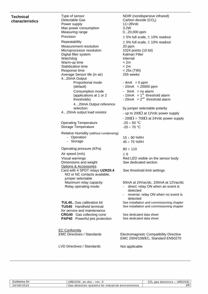
The control card can be expanded with a relay card inserted into a dedicated connector CN3 with four SPDT relays that will be activated under the following conditions: pre-alarm, 1st threshold alarm 2nd threshold alarm and sensor fail, and relative LED alerts. To install the card, follow the instructions below: Step 1: Insert the connection slot provided with the relay card into the control card, making sure the flexible tab is towards the main terminal board. Find CN3 connector.
CN3 connector
Connection slot (flexible tab)
Step 2: Fit the relay card snugly and pull the flexible tab of the connection slot towards the main terminal board. Flexible tab
Step 3: Check the position of the card. Make sure that all the card pins fit into the CN3 connector and push slightly upwards to check that the flexible tab on the connection slot keeps the card in place.
Step 4: Tick the check box with a permanent marker to indicate the presence of the relay card in the device
TYPE URD20SI
IP65

EsiWelma Srl URD20SI_en.doc - rev. 0 CO2 gas detectors – URD20SI 24/09/2010 Gas detection systems for industrial environments 6/8
Electrical installation of the optional relay card
Selecting the type of contact on the terminal board:
Configuring the relay operating mode:
After mechanically installing the relay card, it is necessary to configure it electrically, selecting the relay operating mode and the type of contact desired on the terminal board (NC or NO).
A pair of extractable terminals is available for each relay; the type of contact (NC or NO) to be associated with them can be selected using the JP1…JP4 jumpers. NC or NO contact of pre-alarm relay NC or NO contact of 1nd THRESHOLD relay NC or NO contact of 2nd THRESHOLD relay NC or NO contact of FAIL relay DL1 (yellow), Sensor FAIL
DL2 (red), 2nd alarm THRESHOLD
DL3 (red), 1st alarm THRESHOLD DL4 (red), Pre-alarm
Selecting the terminal contact: NC NO To set the operating mode of the relays: for direct (relay energised by event) or reverse (relay energised with no event), it is necessary to use the 6th selector of the DIP switch at S1; in particular:
direct operating mode reverse operating mode
Checklist after mechanical and electrical installation
The sensors are factory calibrated so they normally do not require any other calibration once installed. Still, after installation, an operational check of the sensors is recommended. The detector will enter a 2-minute warm-up phase after power-up. After this time, the sensor will switch to normal operating mode, but it will take about 2 hours before it reaches top performance level. When the detector is operating, a gas response check should be carried out using the TUL40.. gas calibration kit. This kit contains: - 2 calibration gas cylinder: 1 x 5000ppm of CO2; 1 x Pure Nitrogen
(see kit part numbers on the specific technical data sheet) - pressure valve and flow regulator - sensor body adapter - about 2 metres of hose between cylinder and adapter. During the test, check the output current, the status of the LED outside the enclosure on the sensor body and, if present, the status of the LEDs on the relay card before closing the housing.
The LED on the sensor body and the 4...20mA output have the following operating meaning:
Sensor status 4...20mA Output Status LED on sensor body WARM-UP 2mA Flashing at 2Hz frequency OPERATING 1 flash about every 10 sec. PRE-ALARM 2 flashes about every 5 sec. 1st ALARM THRESHOLD 3 flashes about every 5 sec. 2nd ALARM THRESHOLD
4...20mA 0,10,20mA for
threshold applications 4 flashes about every 5 sec.
SENSOR FAIL 22mA Steady
1 2 3 4 5 6 7 8
ON
1 2 3 4 5 6 7 8
ON
D | C B | A
EsiWelma Srl URD20SI_en.doc - rev. 0 CO2 gas detectors – URD20SI 24/09/2010 Gas detection systems for industrial environments 7/8
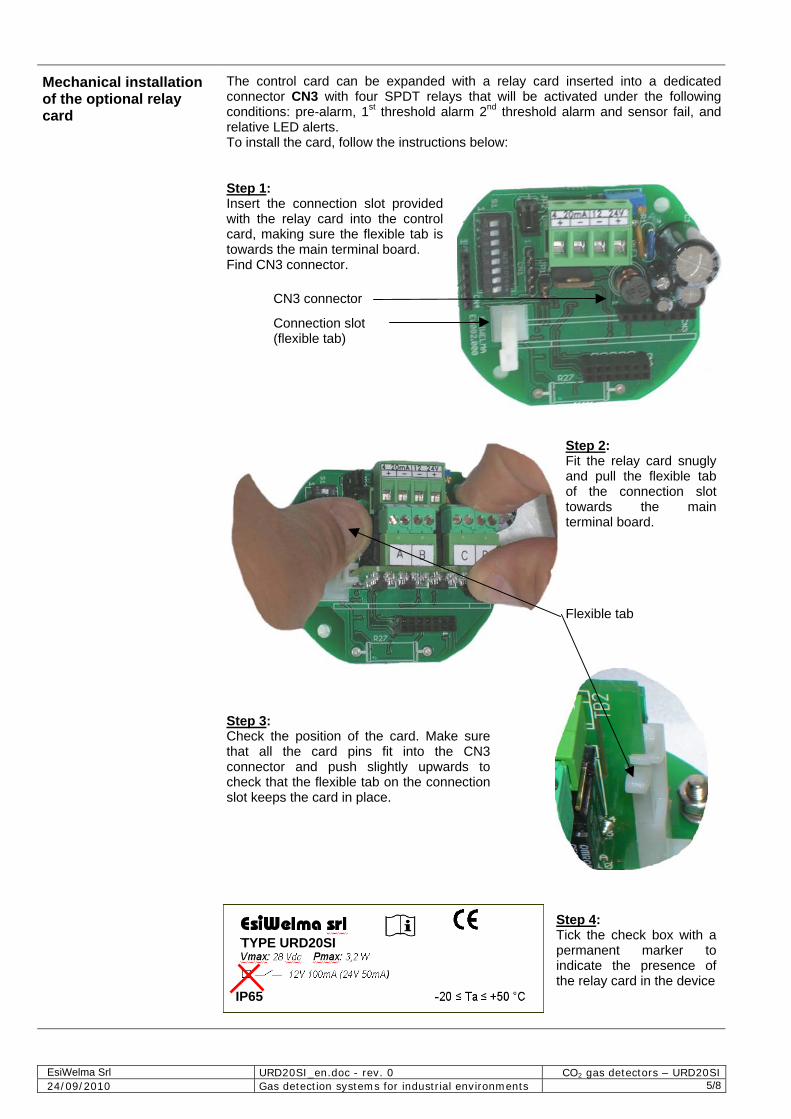
Checklist after mechanical and electrical installation (continued)
Use the calibration kit to apply the gas mixture at 5000ppm of CO2, making sure that the 4...20mA output is between 7 and 9mA (theoretic value 8mA), and that the status LED and the pre-alarm, 1st and 2nd alarm threshold on the optional relay card switch on according to the threshold settings. Use the Pure Nitrogen gas cylinder to check the zero calibration.
Maintenance Routine
Corrective
Decommissioning
A sensor functional test should be carried out every three-six months.
Routine maintenance involves repeating the same tests as set forth in “checklist after mechanical and electrical installation”.
If any abnormalities are found during routine sensor maintenance, return the sensor concerned to the supplier / installer, who in turn will send it back to the manufacturer. Sensors may need to be re-calibrated, using the TUL40.. gas calibration kit and the TUS40 handheld terminal, which must be connected to the sensor via the communication interface integrated in the cable (on the connector CN4). For the re-calibration procedure, see the instructions supplied with the handheld terminal.
Remove power from the detector, disconnect all wiring and conduits and dismount the housing from all the blocking systems.
Warranty Warranty on EsiWelma products is valid for 12 months from installation date and no longer than 24 months from manufacturing date on the product. Installation data, stamp and signature on the data sheet filled in by the installer will be considered proof for warranty. A copy of the warranty data sheet must be sent when returning the product under warranty.
Accessories UZR20.4 Four-relay card TUL40.. Gas calibration Kit TUS40 Handheld terminal CRG40 Gas collecting cone PAP40 Powerful jets protection
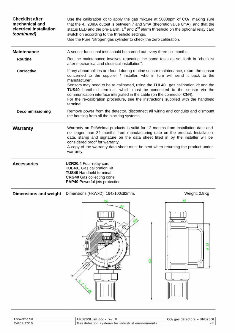
Dimensions and weight
Dimensions (HxWxD): 164x100x82mm. Weight: 0.8Kg

EsiWelma Srl URD20SI_en.doc - rev. 0 CO2 gas detectors – URD20SI 24/09/2010 Gas detection systems for industrial environments 8/8
Installation data
To be filled in by Installer Installer's stamp and signature
Installation site: Product order number: Part Number:
Manufacturing date:
Installation date:
Replacement date:
Routine checks
To be filled in by Installer / Service Personnel Signature
Remarks …………………………………………………………………………………………………………….. …………………………………………………………………………………………………………….. …………………………………………………………………………………………………………….. …………………………………………………………………………………………………………….. …………………………………………………………………………………………………………….. …………………………………………………………………………………………………………….. …………………………………………………………………………………………………………….. …………………………………………………………………………………………………………….. …………………………………………………………………………………………………………….. …………………………………………………………………………………………………………….. …………………………………………………………………………………………………………….. ……………………………………………………………………………………………………………..