Embed Size (px)
Citation preview
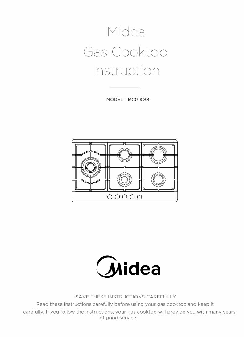
MCG90SS
Midea
Instruction
MODEL :
SAVE THESE INSTRUCTIONS CAREFULLY
Read these instructions carefully before using your gas cooktop,and keep it
carefully. If you follow the instructions, your gas cooktop will provide you with many years of good service.
Gas Cooktop

Preface
Thank you for choosing our gas cooktop. To use this appliance correctly and prevent any potential risk, read these instructions before using the appliance.Keep these instructions in a place where you can find them easily.If you are unsure of any of the information contained in these instructions, please contact our customer care centre.
The manufacturer shall not be responsible for any damages to persons or property caused by incorrect installation or use of the appliance.The appliance has been certified for use in countries other than those marked on the appliance.
The manufacturer also reserves the right to make any modifications to the products as may be considered necessary or useful, also in the interests of the user, without jeopardising the main functional and safety features of the products themselves.The appliance is designed for a domestic environment and not a commercial one.
1
contents
Preface
Instructions for use and maintenance
Safety Warning
Safety Instructions Installation Child and People Safety During Use Cleaning and Service 8 Environmental Information
Description of the appliance How to Use the appliance Safety and Energy saving advice Cleaning and Maintenance
Technical instructions
6
16 17182
15
13 12
2
2
4
543
8
9 10
2
2
Using instructions Positioning Installing the appliance Gas ConnectionGas Specifition Electrical Connection Gas adjustment Trouble shooting
3
5
2
Safety Instructions
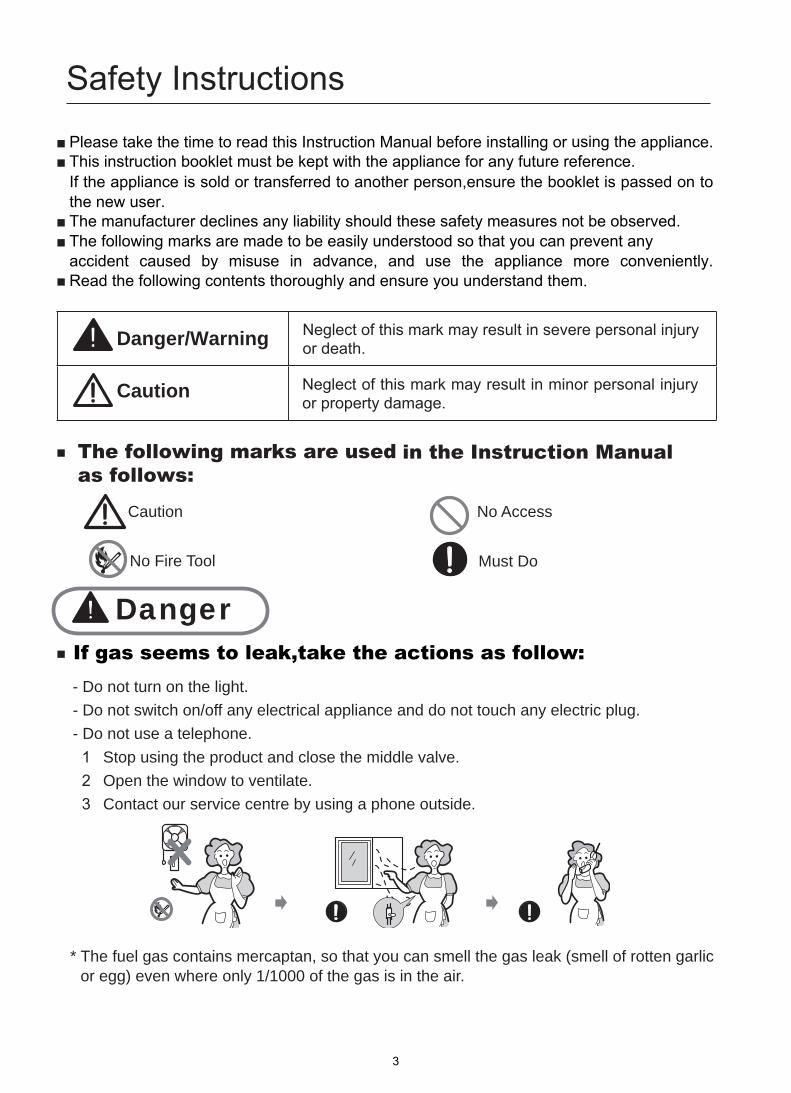
Danger/Warning
Caution Neglect of this mark may result in minor personal injury or property damage.
Caution No Access
No Fire Tool Must Do
Danger
- Do not turn on the light. - Do not switch on/off any electrical appliance and do not touch any electric plug. - Do not use a telephone.
1 Stop using the product and close the middle valve. 2 Open the window to ventilate.
3 Contact our service centre by using a phone outside.
cilrag nettor fo llems( kael sag eht llems nac uoy taht os ,natpacrem sniatnoc sag leuf ehT *or egg) even where only 1/1000 of the gas is in the air.
The following marks are used in the Instruction Manual as follows:
If gas seems to leak,take the actions as follow:
Neglect of this mark may result in severe personal injury or death.
Please take the time to read this Instruction Manual before installing or using the appliance. .
If the appliance is sold or transferred to another person,ensure the booklet is passed on to the new user.
T accident caused by misuse in advance, and use the appliance more conveniently. R .
3
Installation
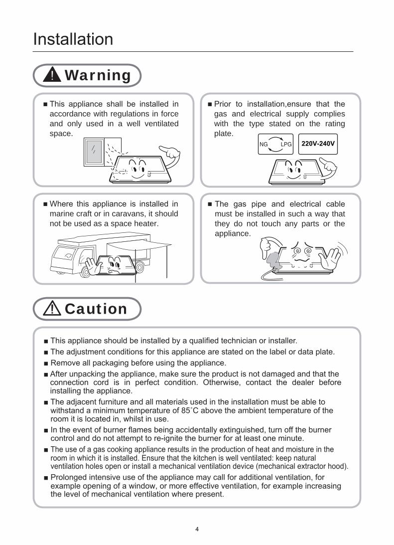
Warning
This appliance shall be installed in accordance with regulations in force and only used in a well ventilated space.
Prior to installation,ensure that the gas and electrical supply complies with the type stated on the rating plate.
Where this appliance is installed in marine craft or in caravans, it should not be used as a space heater.
The gas pipe and electrical cable must be installed in such a way that they do not touch any parts or the appliance.
Caution
220V-240V
connection cord is in perfect condition. Otherwise, contact the dealer before installing the appliance.
room it is located in, whilst in use.
control and do not attempt to re-ignite the burner for at least one minute.The use of a gas cooking appliance results in the production of heat and moisture in the room in which it is installed. Ensure that the kitchen is well ventilated: keep natural
the level of mechanical ventilation where present.
4
Child and People Safety
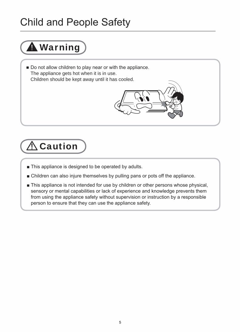
Do not allow children to play near or with the appliance.The appliance gets hot when it is in use. Children should be kept away until it has cooled.
Warning
Caution
from using the appliance safety without supervision or instruction by a responsible person to ensure that they can use the appliance safety.
5
During Use
Warning
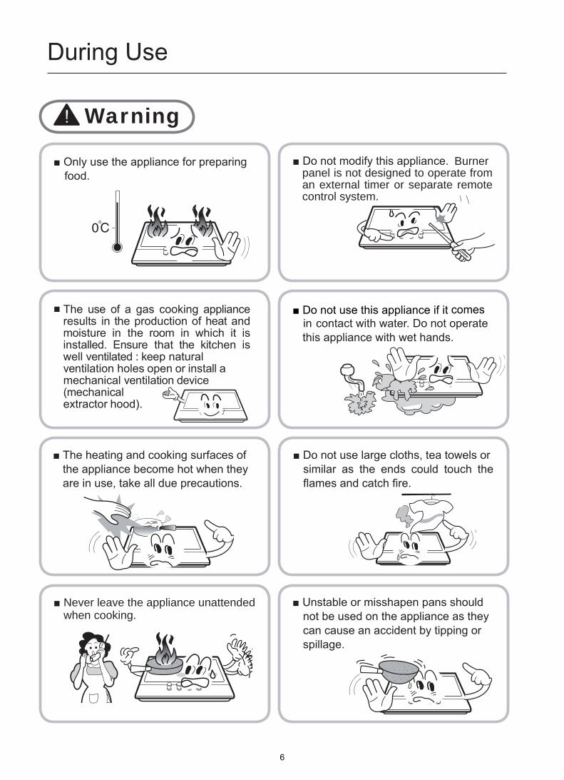
The use of a gas cooking appliance results in the production of heat and moisture in the room in which it is installed. Ensure that the kitchen is well ventilated : keep naturalventilation holes open or install amechanical ventilation device(mechanical extractor hood).
Never leave the appliance unattended when cooking.
Burner panel is not designed to operate from an external timer or separate remote control system.
food.
contact with water. Do not operate this appliance with wet hands.
comes
the appliance become hot when they are in use, take all due precautions.
similar as the ends could touch the
not be used on the appliance as they can cause an accident by tipping or spillage.
6
During Use
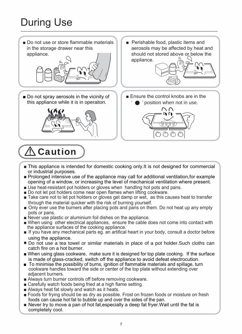
this appliance while it is in operaiton. ‘ ’ position when not in use.
Caution
materials in the storage drawer near this appliance.
aerosols may be affected by heat and should not stored above or below the appliance.
This appliance is intended for domestic cooking only.It is not designed for commercial or industrial purposes.Prolonged intensive use of the appliance may call for additional ventilation,for example opening of a window, or increasing the level of mechanical ventilation where present.
O
is made of glass-cracked, switch off the appliance to avoid defeat electrocution. adjacent burners.
If the surface
using the appliance. Do not use a tea towel or similar materials in place of a pot holder.Such cloths can catch fire on a hot burner.
foods can cause hot fat to bubble up and over the sides of the pan.Never try to move a pan of hot fat,especially a deep fat fryer.Wait until the fat is completely cool.
pots or pans.
the appliance surfaces of the cooking appliance.
7

Cleaning and Service
Environmental Information
unusable, by cutting off the cable.
disposed with other household wastes at the end of its working life. To prevent possible harm to the environment or human health from uncontrolled waste disposal, please separate this from other types of wastes and recycle it responsibly to promote the sustainable reuse of material resources.
agents.
Warning
and cooled.
clean the appliance.
or serviced by an authorised Service Engineer and only genuine approved spare parts should be used.
Caution
cleaning repaired
with due regard to safety and the environment.
for environmentally safe recycling.
wastes for disposal.
Correct Disposal of This Product(Waste Electrical & Electronic Equipment)
8

Description of the appliance
Model ΣQn
860*510*90
Continuous Ignition
Type G1/2 thread
2W
220-240Vac,50Hz-60Hz,Stainless
Ignition device
Gas Connection
Electric supply
Burner Feature
Dimension(W*D*H) Top Plate
Steel
Rapid (1), Semi-rapid(2), Auxiliary (1), Triple-Crown(1)
MCG90SS 41.2MJ/h
9
A
How to Use the appliance
ccessories
Description of the appliance
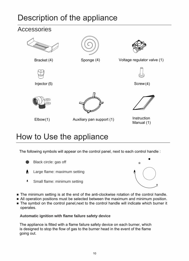
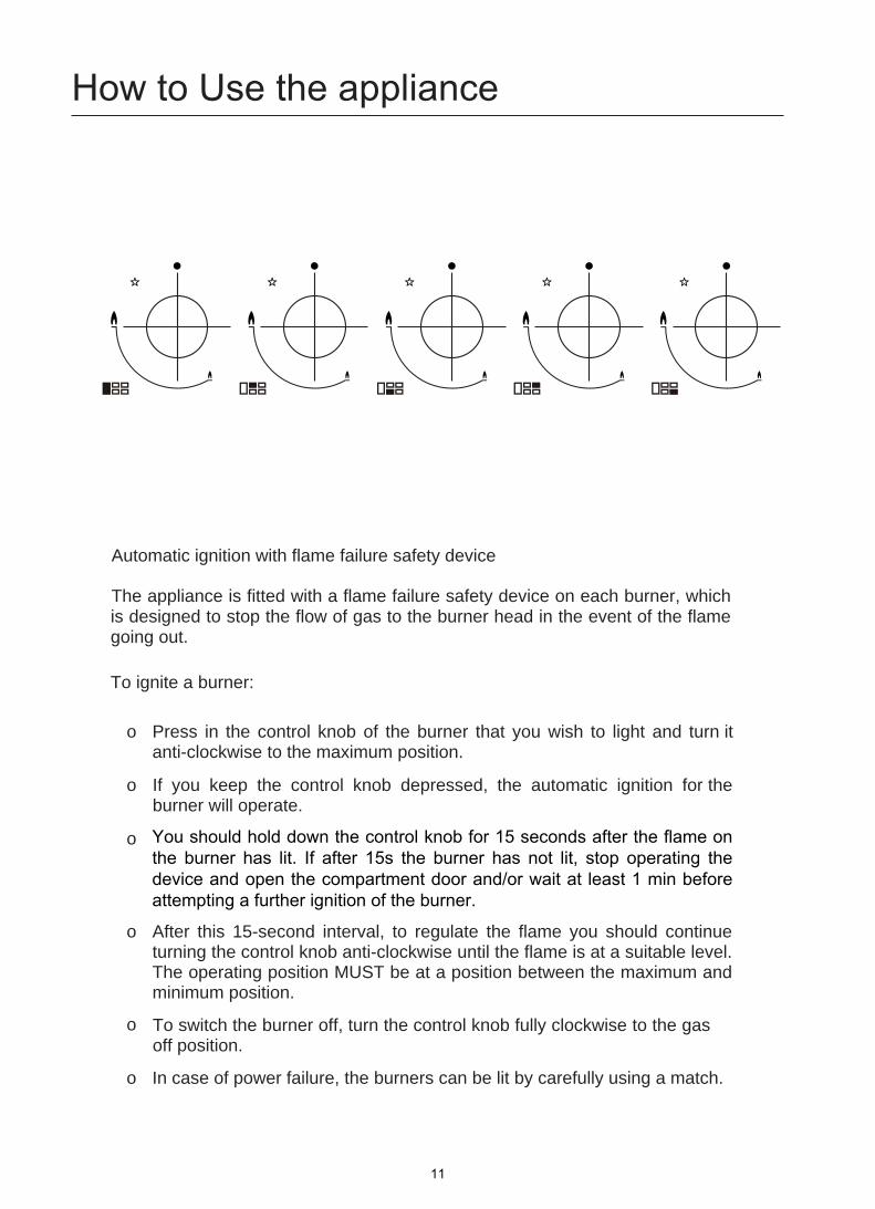
Black circle: gas off
Large flame: maximum setting
Small flame: minimum setting
Automatic ignition with flame failure safety device
Bracket (4) Sponge (4)
Screw (4)
Elbow (1) Auxiliary pan support (1)
(5)
Instruction Manual (1)
Voltage regulator valve (1)
The appliance is fitted with a flame failure safety device on each burner, which is designed to stop the flow of gas to the burner head in the event of the flame going out.
Injector
The minimum setting is at the end of the anti-clockwise rotation of the control handle. All operation positions must be selected between the maximum and minimum position. The symbol on the control panel,next to the control handle will indicate which burner it operates.
10
How to Use the appliance
Automatic ignition with flame failure safety device
The appliance is fitted with a flame failure safety device on each burner, which is designed to stop the flow of gas to the burner head in the event of the flame going out.
To ignite a burner:
o Press in the control knob of the burner that you wish to light and turn itanti-clockwise to the maximum position.
o If you keep the control knob depressed, the automatic ignition for theburner will operate.
o
o After this 15-second interval, to regulate the flame you should continueturning the control knob anti-clockwise until the flame is at a suitable level.The operating position MUST be at a position between the maximum andminimum position.
o To switch the burner off, turn the control knob fully clockwise to the gasoff position.
o In case of power failure, the burners can be lit by carefully using a match.
You should hold down the control knob for 15 seconds after the flame onthe burner has lit. If after 15s the burner has not lit, stop operating thedevice and open the compartment door and/or wait at least 1 min beforeattempting a further ignition of the burner.
11

Safety and Energy saving advice- The diameter of the bottom of the pan should correspond to that of the burner.
BURNERS200mm 240mm200mm 240mm160mm
NO YES
120mm 160mm180mm
Triple-Crown Rapid
Semi-Rapid Auxiliary
PANSmin. max.
Do not use small diameter cookware on large burners.The flame should never come up the sides of the cookware.
Avoid cooking without a lid or with the lid half off-as this wastes energy
Do not use a pan with a convex or concave bottom.
Do not place cookware on one side of a burner,as it could tip over.Do not use cookware with a large diameter on the burners near the controls,which when placed on the middle of the burner may touch the controls or be so close to them that they increase the temperature in this area and may cause damage.
Never place cookware directly on top of the burner.
Do not place anything,eg.flame tamer,asbestos mat,between pan and pan support as serious damage to the appliance may result.
Do not use excessive weight and do not hit the cooktop with heavy objects.
Always use cookware that is suitable for each burner, to avoid wasting gas and discolouring the cookware.
Place a lid on the cookware.
Only use pots,saucepans and frying pans with a thick,flat bottom.
Always place the cookware right over the burners,not to one side.
Place the cookware on top of the trivet.
Handle cookware carefully when they are on the burner.
of the burner.
It is not recommended to use roasting pans,frying pans or grill stones heated simultaneously on several burners because the resulting heat build-up may damage the appliance.
Do not touch the top plate and trivet whilst in use for a certain period after use.
As soon as a liquid starts boiling,turn down the flame so that it will barely keep the liquid simmering.
12
Cleaning and Maintenance
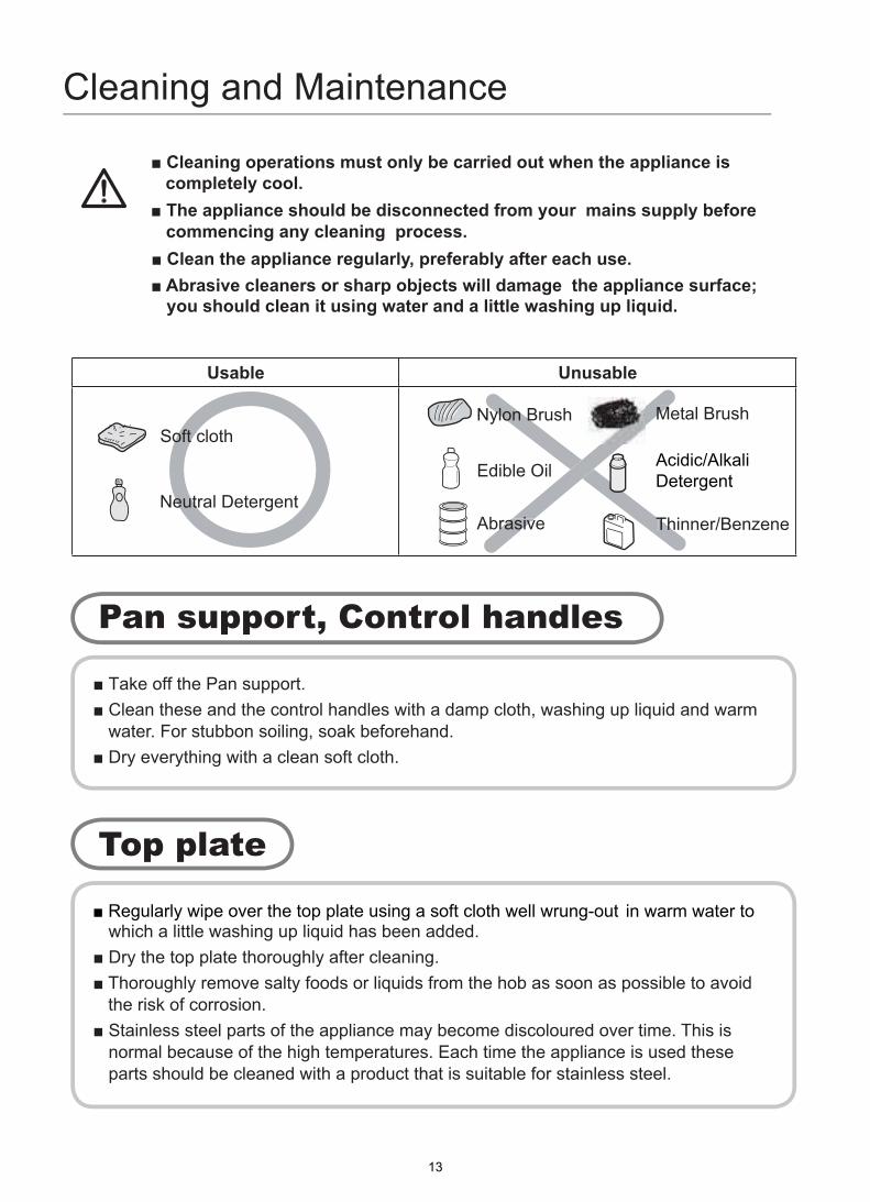
Soft cloth
Neutral Detergent
Nylon Brush
Edible Oil
Abrasive
Detergent
Thinner/Benzene
Metal Brush
Acidic/Alkali
water. For stubbon soiling, soak beforehand.
rung-out
the risk of corrosion.
normal because of the high temperatures. Each time the appliance is used these parts should be cleaned with a product that is suitable for stainless steel.
is completely cool.
13

Cleaning and Maintenance
2 1 2
3 3
4 4
5 7
6 6
7 5
1.Place the flame spreader ( 4 ) on to the burner cup ( 5 ) so that the ignition deviceand the flame supervision device extend through their respective holes in the flamespreader.The flame spreader must click into place correctly.
2.Position the burner lid ( 1,2,3 ) onto the flame speader ( 4 ) so that the retaining pinsfit into their respective recesses.
from the top plate. detergent or washing up liqui.
cloth and wipe dry with a clean cloth.
blocked.
14
Warnings
Using instructions
appliance may
installation
be installed and connected in accordance with current
Grease cranes produced at the factory to meet the requirement of all life hob.
15
Positioning
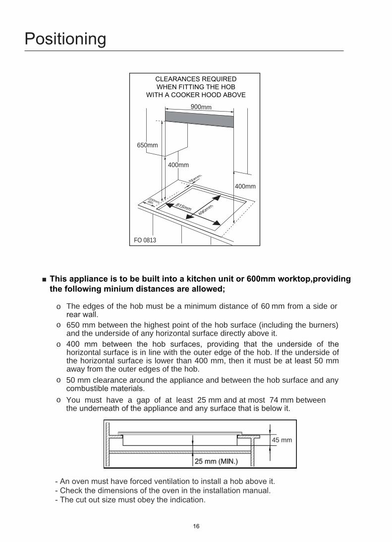
The edges of the hob must be a minimum distance of mm from a side or rear wall.
mm between the highest point of the hob surface (including the burners) and the underside of any horizontal surface directly above it.400 mm between the hob surfaces, providing that the underside of the horizontal surface is in line with the outer edge of the hob. If the underside of the horizontal surface is lower than 400 mm, then it must be at least 50 mm away from the outer edges of the hob.50 mm clearance around the appliance and between the hob surface and any combustible materials.
45 mm
60
You must have a gap of at least 25 mm and at most 74 mm between the underneath of the appliance and any surface that is below it.
o
o
o
o
o 650
CLEARANCES REQUIRED WHEN FITTING THE HOB
WITH A COOKER HOOD ABOVE
900mm
400mm
400mm
FO 0813
60mm
490mm in
0.0mmM
2
This appliance is to be built into a kitchen unit or 600mm worktop,providing the following minium distances are allowed;
- An oven must have forced ventilation to install a hob above it.- Check the dimensions of the oven in the installation manual.- The cut out size must obey the indication.
815mm
16
6 50mm
Installing the appliance
Bottom view
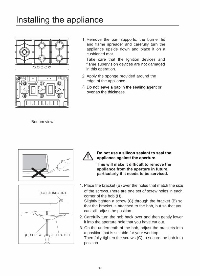
of the screws.There are one set of screw holes in each corner of the hob (H) . Slightly tighten a screw (C) through the bracket (B) so that the bracket is attached to the hob, but so that you can still adjust the position .
.2 Carefully turn the hob back over and then gently lowerit into the aperture hole that you have cut out.
.3 On the underneath of the hob, adjust the brackets intoa position that is suitable for your worktop.Then fully tighten the screws (C) to secure the hob intoposition.
(A) SEALING STRIP
(C) SCREW (B) BRACKET
Remove the pan supports, the burner lid and flame spreader and carefully turn the appliance upside down and place it on a cushioned mat. Take care that the Ignition devices and flame supervision devices are not damaged in this operation.
2. Apply the sponge provided around theedge of the appliance.
3.
1.
Do not leave a gap in the sealing agent oroverlap the thickness.
Do not use a silicon sealant to seal the appliance against the aperture.
17
Gas Connection
Keep away from inflammable materials around appliance.Before work, put on gloves.CAUTIONCool off the appliance for a while right after using appliance for your safety because you can get burners by high temperature from the appliances.
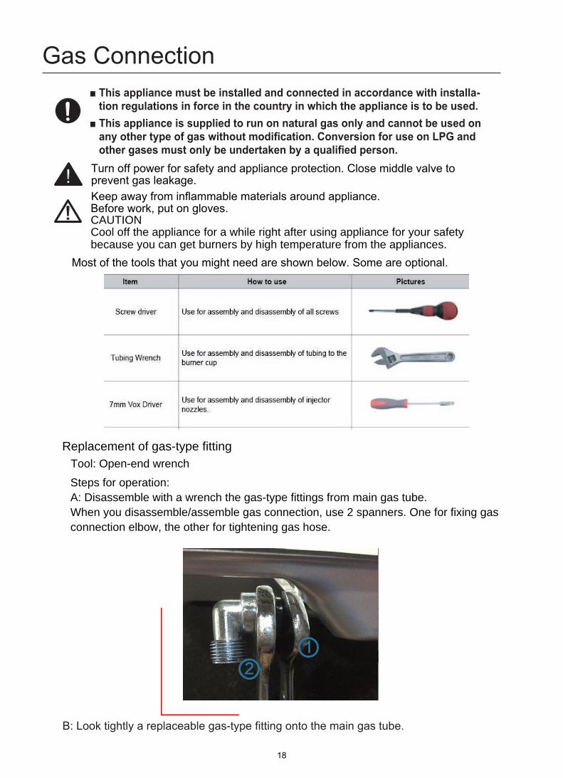
B: Look tightly a replaceable gas-type fitting onto the main gas tube.
Turn off power for safety and appliance protection. Close middle valve to prevent gas leakage.
Most of the tools that you might need are shown below. Some are optional.
Replacement of gas-type fittingTool: Open-end wrench
Steps for operation:A: Disassemble with a wrench the gas-type fittings from main gas tube.When you disassemble/assemble gas connection, use 2 spanners. One for fixing gas connection elbow, the other for tightening gas hose.
12
18
Once�these�checks�have�been�completed,�if�the�regulator still fails to perform in a satisfactory manner it should be replaced.
9.� One�by�one,�turn�the�knobs�to�minimum�and�screw�in the bypass screw (accessible when the knob isremoved) until a small stable flame results. turn theknob to maximum and then back to minimum toensure that the correct minimum flame is maintained.
10.� ��Attach�the�LPG�sticker�to�the�cooker,�near�the�gassupply inlet. Cover the natural Gas label that isfactory fitted.
LpG ConVErSIon - rEGuLAtor
this appliance is supplied set up for natural Gas usage. A conversion kit is included with the product for universal LpG usage. the conversion kit contains the appropriate injectors and 1 LpG sticker.
please follow the procedure below if a conversion to suit unIVErSAL LpG is required:
1.� Remove�the�hotplate�trivets,�burner�caps�and�burner�crowns to access the hotplate injectors. replace thefactory�fitted�injectors�with�the�appropriate�injectors,�as�supplied. refer to injector orifice table for injector sizes.the injector size is stamped on the side of the injector.
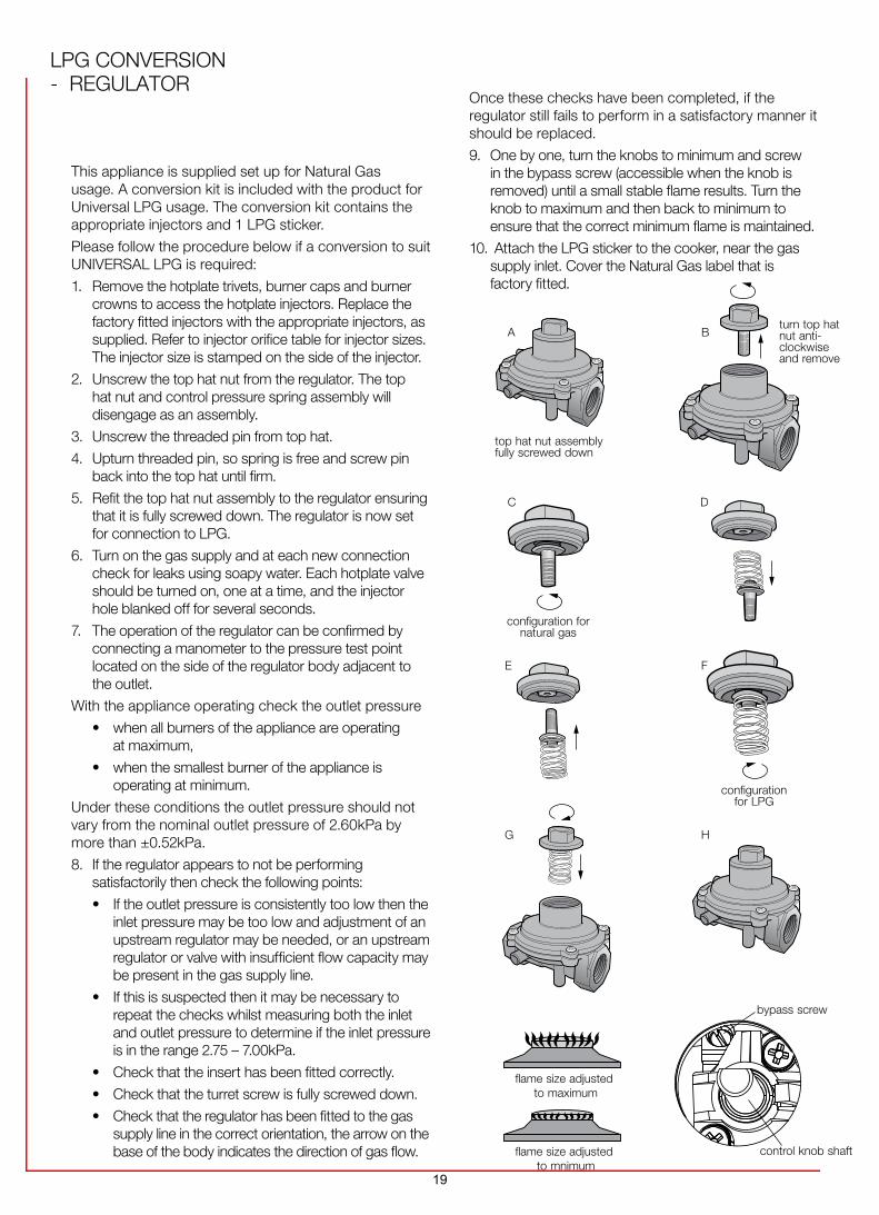
2. unscrew the top hat nut from the regulator. the tophat nut and control pressure spring assembly willdisengage as an assembly.
3. unscrew the threaded pin from top hat.
4.� �Upturn�threaded�pin,�so�spring�is�free�and�screw�pinback into the top hat until firm.
5. refit the top hat nut assembly to the regulator ensuringthat it is fully screwed down. the regulator is now setfor connection to LpG.
6. turn on the gas supply and at each new connectioncheck for leaks using soapy water. Each hotplate valveshould�be�turned�on,�one�at�a�time,�and�the�injector�hole blanked off for several seconds.
7. the operation of the regulator can be confirmed byconnecting a manometer to the pressure test pointlocated on the side of the regulator body adjacent tothe outlet.
With the appliance operating check the outlet pressure
•� when all burners of the appliance are operatingat�maximum,
•� when the smallest burner of the appliance isoperating at minimum.
under these conditions the outlet pressure should not vary from the nominal outlet pressure of 2.60kpa by more than ±0.52kpa.
8. If the regulator appears to not be performingsatisfactorily then check the following points:
•� If the outlet pressure is consistently too low then theinlet pressure may be too low and adjustment of anupstream�regulator�may�be�needed,�or�an�upstream�regulator or valve with insufficient flow capacity maybe present in the gas supply line.
•� If this is suspected then it may be necessary torepeat the checks whilst measuring both the inletand outlet pressure to determine if the inlet pressureis in the range 2.75 – 7.00kpa.
•� Check that the insert has been fitted correctly.
•� Check that the turret screw is fully screwed down.
•��
Check that the regulator has been fitted to the gassupply�line�in�the�correct�orientation,�the�arrow�on�thebase of the body indicates the direction of gas flow.
A Bturn top hat nut anti-clockwise and remove
top hat nut assembly fully screwed down
G H
C D
configuration for natural gas
E f
configuration for LpG
bypass screw
control knob shaftflame size adjusted to mnimum
adjustedflame size maximum to
19

Gas ConnectionStatutory requirementsThis installation must conform with the following:■ Manufacturer’s Installation instructions■ Local Gas Fitting Regulations■ Municipal Building Codes■ Refer to AS/NZS 5601.1 for Gas Installations■ S.A.A. Wiring Code■ Local Electrical Regulations■ Any other statutory regulations
Preparing to installRefer to AS/NZS 5601.1 for piping size details. These built-in cooktops are intended to be inserted in a benchtop cutout. Only an officially authorised technician should connect the appliance. Before you begin, turn off the gas and electricity supply.
A full operational test and a test for possible leakages must be carried out by the fitter after installation.Access to the whole length of the connection hose must be possible and the gas hose must be replaced before its use before the end of service life (indicated on the hose.)Before Leaving-Check all connections for gas leaks with soap and water.DO NOT use a naked flame for detecting leaks. Ignite all burners both individually and concurrently to ensure correct operation of gas valves, burners and ignition. Turn gas taps to low flame position and observe stability of the flame for each burner individually and all together. Adhere the duplicate data plate to an accessible location near the hotplate. When satisfied with the hotplate, please instruct the user on the correct method of operation. In case the appliance fails to operate correctly after all checks have been carried out, refer to the auth orised service provider in your area.
LPG gas connectionNatural gas connection
115 115
pressure test point pressure test point LPG CONVERSION - REGULATOR
20
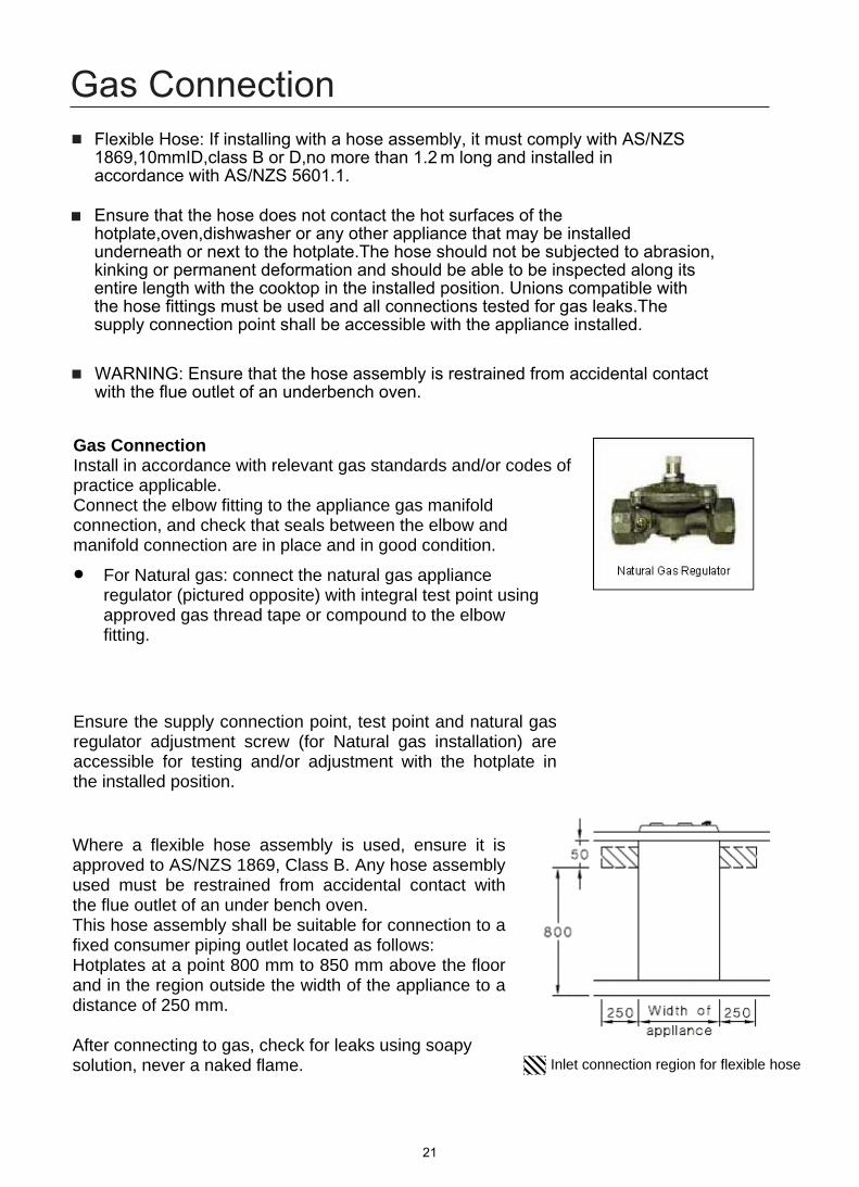
Where a flexible hose assembly is used, ensure it is approved to AS/NZS 1869, Class B. Any hose assembly used must be restrained from accidental contact with the flue outlet of an under bench oven. This hose assembly shall be suitable for connection to a fixed consumer piping outlet located as follows:Hotplates at a point 800 mm to 850 mm above the floor and in the region outside the width of the appliance to a distance of 250 mm.
After connecting to gas, check for leaks using soapy solution, never a naked flame. Inlet connection region for flexible hose
Gas Connection Install in accordance with relevant gas standards and/or codes of practice applicable. Connect the elbow fitting to the appliance gas manifold connection, and check that seals between the elbow and manifold connection are in place and in good condition. For Natural gas: connect the natural gas appliance
regulator (pictured opposite) with integral test point usingapproved gas thread tape or compound to the elbowfitting.
Ensure the supply connection point, test point and natural gas regulator adjustment screw (for Natural gas installation) are accessible for testing and/or adjustment with the hotplate in the installed position.
■
■
■
Flexible Hose: If installing with a hose assembly, it must comply with AS/NZS
accordance with AS/NZS 5601.1.
Ensure that the hose does not contact the hot surfaces of the hotplate,oven,dishwasher or any other appliance that may be installed underneath or next to the hotplate.The hose should not be subjected to abrasion, kinking or permanent deformation and should be able to be inspected along its entire length with the cooktop in the installed position. Unions compatible with the hose fittings must be used and all connections tested for gas leaks.The supply connection point shall be accessible with the appliance installed.
WARNING: Ensure that the hose assembly is restrained from accidental contact with the flue outlet of an underbench oven.
Gas Connection
1869,10mmID,class B or D,no more than 1.2 m long and installed in
21
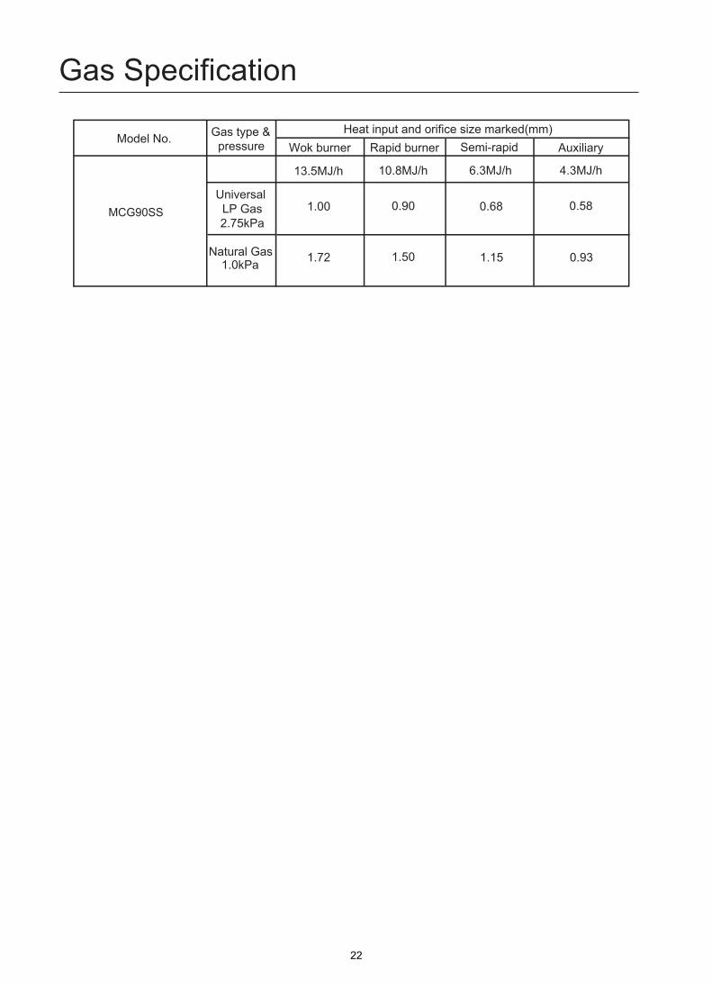
Gas Specification
Wok burner Rapid burner Semi-rapid AuxiliaryHeat input and orifice size marked(mm)
Model No. Gas type &pressure
6.3MJ/h
0.68 0.58
1.15 0.93
13.5MJ/h
1.00
1.72
Natural Gas 1.0kPa
10.8MJ/h
0.90
1.50
MCG90SSUniversal LP Gas2.75kPa
4.3MJ/h
22
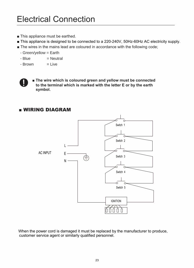
Electrical Connection
- Green/yellow = Earth - Blue = Neutral - Brown = Live
■ This appliance is designed to be connected to a 220-240V, 50Hz-60Hz AC electricity supply.
When the power cord is damaged it must be replaced by the manufacturer to produce, customer service agent or similarly qualified personnel.
Switch 1
Switch 2
AC INPUTSwitch 3
Switch 4
IGNITION
L
E
N
Switch 5
23

Gas adjustment
1
2Injector
Control handle
TapSealing ring
Remove the pan support, Burner lid and Flame spreader.
Unscrew the injector using a 7mm box spanner and replace it with the stipulated injector for new gas supply. Carefully reassemble the all components. After injectors are replaced, it is advisable to strongly tighten the injector in place.
Adjustment of minimum level of the flame.Turn the taps down to minimum.
-
Remove the knob from the tap and place a small bladed screwdriver in the centre of the tap shaft. The correct adjustment is obtained when the flame has a length of about 3 - 4 mm.- For butane / propane gas, the adjusting screw must
Make sure that the flame does not go out by quickly turning from maximum flow to minimum flow. If it does then remove the control knob and make further adjustments to the gas flow, testing it again once the adjustment has been made.
Repeat this process for each one of the gas taps.
be tightly screwed in. Refit the control knob.-
Change the injector of the burners.
Do not dismantle the tap shafe:
Attach the ULPG sticker to the cooker, near the gas supply inlet. Cover the Natural label that is factory fitted.
5
24
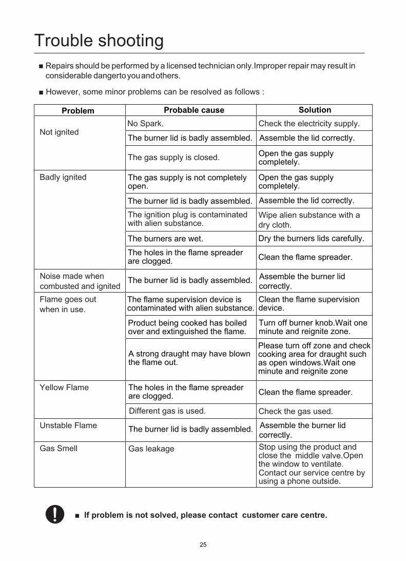
Trouble shooting
Not ignitedNo Spark. Check the electricity supply.
Badly ignited
The gas supply is closed.
The ignition plug is contaminated with alien substance.
Noise made when combusted and ignitedFlame goes out when in use.
Yellow Flame
Different gas is used. Check the gas used.
Unstable Flame
Gas Smell
Wipe alien substance with a dry cloth.
Gas leakage Stop using the product and close the middle valve.Open the window to ventilate. Contact our service centre by using a phone outside.
Repairs should be performed by a licensed technician only.Improper repair may result in considerable danger to you and others.
The burner lid is badly assembled. Assemble the lid correctly.
The gas supply is not completely open.
Open the gas supply completely.
The burners are wet. Dry the burners lids carefully.
The holes in the flame spreader are clogged. Clean the flame spreader.
The burner lid is badly assembled. Assemble the burner lidcorrectly.
The flame supervision device is contaminated with alien substance.
Open the gas supply completely.
The burner lid is badly assembled. Assemble the lid correctly.
Clean the flame supervision device.
Product being cooked has boiled over and extinguished the flame.
Turn off burner knob.Wait one minute and reignite zone.
A strong draught may have blown the flame out.
Please turn off zone and check cooking area for draught such as open windows.Wait one minute and reignite zone
The holes in the flame spreader are clogged. Clean the flame spreader.
The burner lid is badly assembled. Assemble the burner lidcorrectly.
Problem Probable cause Solution
centre.
25


