Embed Size (px)
Citation preview

The Chamberlain Group, Inc.845 Larch AvenueElmhurst, Illinois 60126-1196www.chamberlain.com
GARAGE DOOR OPENER
Models PD752D 3/4 HPPD752KLD 3/4 HP
For Residential Use Only
Owner’s Manual■ Please read this manual and the enclosed safety materials carefully!
■ Fasten the manual near the garage door after installation.
■ The door WILL NOT CLOSE unless The Protector System® is connectedand properly aligned.
■ Periodic checks of the opener are required to ensure safe operation.
■ The model number label is located on the left side panel of your opener.
®

2
TABLE OF CONTENTS
When you see these Safety Symbols and SignalWords on the following pages, they will alert you tothe possibility of serious injury or death if you donot comply with the warnings that accompany them.The hazard may come from something mechanicalor from electric shock. Read the warnings carefully.
When you see this Signal Word on the followingpages, it will alert you to the possibility of damage toyour garage door and/or the garage door opener ifyou do not comply with the cautionary statementsthat accompany it. Read them carefully.
INTRODUCTIONSafety Symbol and Signal Word Review
This garage door opener has been designed and tested to offer safe service provided it is installed, operated,maintained and tested in strict accordance with the instructions and warnings contained in this manual.
Mechanical
Electrical
WARNING
CAUTION WARNING
WARNING
WARNING
CAUTION WARNING
WARNINGWARNING
CAUTION WARNING
WARNING
Introduction 2-7Safety symbol and signal word review........................2
Preparing your garage door ........................................3
Tools needed...............................................................3
Planning ..................................................................4-5
Carton inventory ..........................................................6
Hardware inventory .....................................................7
Assembly 8-11Assemble the rail and install the trolley ......................8
Fasten the rail to the motor unit andinstall the idler pulley...................................................9
Install the chain/cable................................................10
Tighten the chain .......................................................11
Installation 11-26Installation safety instructions....................................11
Determine the header bracket location .....................12
Install the header bracket..........................................13
Attach the rail to the header bracket.........................14
Position the opener ...................................................15
Hang the opener .......................................................16
Install the door control...............................................17
Install the lights .........................................................18
Attach the emergency release rope and handle .......18
Electrical requirements..............................................19
Install The Protector System® ..............................20-22
Fasten the door bracket .......................................23-24
Connect the door arm to the trolley .....................25-26
Adjustment 27-29Adjust the travel limits ...............................................27
Adjust the force .........................................................28
Test the safety reversal system.................................29
Test The Protector System® ......................................29
Operation 30-34Operation safety instructions.....................................30
Using your garage door opener ................................30
Using the wall-mounted door control ........................31
To open the door manually........................................31
Care of your garage door opener..............................32
Having a problem? ....................................................33
Diagnostic chart.........................................................34
Programming 35-36To add or reprogram a hand-held remote control .....35
To erase all codes .....................................................35
3-Button remotes.......................................................35
To add, reprogram or change a Keyless Entry PIN ..................................................36
Repair Parts 37-38Rail assembly parts...................................................37
Installation parts ........................................................37
Motor unit assembly parts .........................................38
Accessories 39
Repair Parts and Service 40
Warranty 40
3
To prevent damage to garage door and opener:• ALWAYS disable locks BEFORE installing and operating
the opener. • ONLY operate garage door opener at 120V, 60 Hz to
avoid malfunction and damage.
To prevent possible SERIOUS INJURY or DEATH:• ALWAYS call a trained door systems technician if
garage door binds, sticks, or is out of balance. Anunbalanced garage door may not reverse whenrequired.
• NEVER try to loosen, move or adjust garage door, doorsprings, cables, pulleys, brackets or their hardware,ALL of which are under EXTREME tension.
• Disable ALL locks and remove ALL ropes connected togarage door BEFORE installing and operating garagedoor opener to avoid entanglement.
Preparing your garage door
Before you begin:
• Disable locks.
• Remove any ropes connected to garage door.
• Complete the following test to make sure yourgarage door is balanced and is not sticking orbinding:
1. Lift the door about halfway as shown. Releasethe door. If balanced, it should stay in place,supported entirely by its springs.
2. Raise and lower the door to see if there is anybinding or sticking.
If your door binds, sticks, or is out of balance, call atrained door systems technician.
Tools needed
During assembly, installation and adjustment of theopener, instructions will call for hand tools asillustrated below.
WARNING
CAUTION WARNING
WARNING
WARNING
CAUTION WARNING
WARNING
Pliers
Wire Cutters
Claw Hammer
Hack Saw
Screwdriver
Adjustable End WrenchSockets and Wrench1/2", 5/8", 7/16", 9/16" and 1/4"
Drill
Tape Measure
21
Stepladder
Pencil
Drill Bits 3/16", 5/16" and 5/32"
Carpenter'sLevel (optional)
Sectional Door
One-Piece Door

4
Safety Reversing Sensor
Horizontal and vertical reinforcementis needed for lightweight garage doors(fiberglass, steel, aluminum,door with glass panels, etc.).See page 23 for details.
Header Wall
SafetyReversingSensor
Gap between floor and bottom of doormust not exceed 1/4" (6 mm).
Extension Spring
Torsion Spring
Access Door
OR
Slack in chain tensionis normal whengarage door is closed.
Wall-mountedDoor Control
Motor Unit
FINISHED CEILING
Support bracket & fastening hardwareis required.See page 16.
Vertical Centerlineof Garage Door
SECTIONAL DOOR INSTALLATION
Planning
Identify the type and height of your garage door.Survey your garage area to see if any of theconditions below apply to your installation. Additionalmaterials may be required. You may find it helpful torefer back to this page and the accompanyingillustrations as you proceed with the installation ofyour opener.
Depending on your requirements, there are severalinstallation steps which may call for materials orhardware not included in the carton.
• Installation Step 1 – Look at the wall or ceilingabove the garage door. The header bracket mustbe securely fastened to structural supports.
• Installation Step 5 – Do you have a finished ceilingin your garage? If so, a support bracket andadditional fastening hardware may be required.
• Installation Step 10 – Depending upon garageconstruction, extension brackets or wood blocksmay be needed to install sensors.
• Installation Step 10 – Alternate floor mounting ofthe safety reversing sensor will require hardwarenot provided.
Trolley
HeaderWall
GarageDoor
HeaderBracket
StraightDoorArm
EmergencyReleaseRope & Handle
DoorBracket
CurvedDoorArm
GarageDoorSpring Chain
TrolleyStop Bolt
CLOSED POSITION
• Do you have an access door in addition to thegarage door? If not, Model 7702CB EmergencyKey Release is required. See Accessories page.
• Look at the garage door where it meets the floor.Any gap between the floor and the bottom of thedoor must not exceed 1/4" (6 mm). Otherwise, thesafety reversal system may not work properly. SeeAdjustment Step 3. Floor or door should berepaired.
SECTIONAL DOOR INSTALLATIONS• Do you have a steel, aluminum, fiberglass or glass
panel door? If so, horizontal and vertical reinforcement is required (Installation Step 11).
• The opener should be installed above the center ofthe door. If there is a torsion spring or centerbearing plate in the way of the header bracket, itmay be installed within 4 feet (1.22 m) to the left orright of the door center. See Installation Steps 1and 11.
• If your door is more than 7 feet (2.13 m) high, seerail extension kits listed on Accessories page.

5
AccessDoor
SafetyReversing Sensor
SafetyReversingSensorGap between floor
and bottom of doormust not exceed 1/4" (6 mm).
DoorBracket Straight
DoorArmGarage
Door
CLOSED POSITION
HeaderBracket
CurvedDoor Arm
Chain
EmergencyReleaseRope &Handle
Cable
Rail
Trolley Stop Bolt
HeaderWall
Planning (Continued)
ONE-PIECE DOOR INSTALLATIONS• Generally, a one-piece door does not require
reinforcement. If your door is lightweight, refer tothe information relating to sectional doors inInstallation Step 11.
• Depending on your door’s construction, you mayneed additional mounting hardware for the doorbracket (Step 11).
Safety Reversing Sensor
AccessDoor
FINISHED CEILING
Support bracket& fasteninghardware is required.See page 16.
Safety Reversing Sensor
Header Wall
Gap between floor and bottom of door must not exceed 1/4" (6 mm).
Wall-mountedDoor Control
Rail
Motor Unit
Slack in chain tension is normal when garage door is closed.
ONE-PIECE DOOR WITHOUT TRACK
HeaderBracket
Trolley
StraightDoorArm
EmergencyReleaseRope & Handle
Door Bracket
CurvedDoorArmHeader
Wall
Cable
Rail
Garage Door
Trolley Stop Bolt
CLOSED POSITION
Without a properly working safety reversal system,persons (particularly small children) could beSERIOUSLY INJURED or KILLED by a closing garagedoor.• The gap between the bottom of the garage door and
the floor MUST NOT exceed 1/4" (6 mm). Otherwise,the safety reversal system may not work properly.
• The floor or the garage door MUST be repaired toeliminate the gap.
WARNING
CAUTION WARNING
WARNING
ONE-PIECE DOOR WITH TRACK

6
Straight DoorArm Section
Curved DoorArm Section
Safety Labelsand
Literature
2-Conductor Bell WireWhite & White/Red
Chain and CableChain Spreader
Hanging Brackets
Door Bracket
SECURITY✚® 3-ButtonRemote Control with Visor Clip (2)
Trolley
Safety SensorBracket (2)
RailCenter/BackSections
"U" BracketRailFront (header)Section
Idler Pulley
Header Bracket
Motion Detecting Door Control Panel
Motor Unit with 2 Light Lenses
LOCKLIGHT
SECURITY�®
Keyless Entry
The Protector System®
(2) Safety Reversing Sensors(1 Sending Eye and 1 Receiving Eye)with 2-Conductor White & White/BlackBell Wire attached
Your garage door opener is packaged in one cartonwhich contains the motor unit and all parts illustratedbelow. Accessories will depend on the modelpurchased. If anything is missing, carefully check thepacking material. PARTS MAY BE STUCK IN THE
FOAM. Hardware for assembly and installation isshown on the next page. Save the carton andpacking material until installation and adjustment iscomplete.
Carton Inventory
Model PD752KLD ONLY

7
MasterLink (2)
Idler Bolt (1)
Nut3/8" (1)
Trolley Threaded Shaft (1)
Lock Washer3/8" (1)
Lock Nut1/4"-20 (2)
Wing Nut1/4"-20 (2)
Carriage Bolt1/4"-20x1/2" (2)
HandleNut 5/16"-18 (8)Ring Fastener (3)
InsulatedStaples (30)
Drywall Anchors (2)
Clevis Pin5/16"x1" (1)
Rope
Lock Washer 5/16" (7)Lag Screw5/16"-9x1-5/8" (2)
Hex Bolt5/16"-18x7/8" (4)
Clevis Pin5/16"x1-1/4" (1)
Lag Screw5/16"-18x1-7/8" (2)
Screw6ABx1-1/4" (2) Screw 6-32x1" (2)
Clevis Pin5/16"x1-1/2" (1)
Spacer (2)
Washer 5/8" (2)
Spacer (2)
Bolt 1/4"-20x2-1/2 (1)
Bolt 1/4"-20x1-3/4 (1)
Self-Threading Screw1/4"-14x5/8" (2)
Hardware Inventory
Separate all hardware and group as shown below for the assembly and installation procedures.
ASSEMBLY HARDWARE
INSTALLATION HARDWARE

FRONT RAIL(TOP)
KEEP LARGERHOLE ON TOP
8
ASSEMBLY STEP 1Assemble the Rail & Install the Trolley
To avoid installation difficulties, do not run thegarage door opener until instructed to do so.
To prevent INJURY from pinching, keep hands andfingers away from the joints while assembling the rail.
WARNING
CAUTION WARNING
WARNING
Front Rail(TO DOOR)
WindowCut-Out
Screwdriver
IdlerPulleyHole
Tabs
Back Rails(TO MOTOR UNIT)
Trolley
TaperedEnd
TaperedEnd
Inner Trolley
Wear Pads
Outer Trolley
TaperedEnd
TaperedEnd
The front rail has a cut out “window” at the door end(see illustration). The hole above this window islarger on the top of the rail than on the bottom. Asmaller hole 3-1/2" (8.9 cm) away is close to the railedge. Rotate the back rail so it has a similar holeclose to the opposite edge, about 4-3/4" (12 cm)from the far end.
1. Remove the straight door arm and hangingbracket packaged inside the front rail and setaside for Installation Step 5 and 12. NOTE: Toprevent INJURY while unpacking the rail carefullyremove the straight door arm stored within the railsection.
2. Align the rail sections on a flat surface as shownand slide the tapered ends into the larger ones.Tabs along the side will lock into place.
3. Place the motor unit on packing material to protectthe cover, and rest the back end of the rail on top.For convenience, put a support under the frontend of the rail.
4. As a temporary trolley stop, insert a screwdriverinto the hole 10" (25 cm) away from the front ofthe rail, as shown.
5. Check to be sure there are 4 plastic wear padsinside the inner trolley. If they became looseduring shipping, check all packing material. Snapthem back into position as shown.
6. Slide the trolley assembly along the rail from theback end to the screwdriver.

9
To avoid SERIOUS damage to garage door opener, use ONLY those bolts/fasteners mounted in the top ofthe opener.
ASSEMBLY STEP 2Fasten the Rail to the Motor Unit
• Insert a 1/4"-20x2-1/2 bolt, washer and spacer intothe cover protection bolt hole on the back end ofthe rail as shown. Install lower spacer and washerthen tighten securely with a 1/4"-20 lock nut. DoNOT overtighten.
• Remove the bolt and lock nut from the top of themotor unit.
• Attach spreader to the motor unit with two screws.
• Place the “U” bracket, flat side down onto the boltmounted on the motor unit and align the brackethole with the bolt holes. Fasten with the previouslyremoved bolt and lock nut.
• Align the rail assembly with the top of the motorunit. Slide the rail end onto the “U” bracket, all theway to the stops that protrude on the top and sidesof the bracket.
ASSEMBLY STEP 3Install the Idler Pulley
• Lay the chain/cable beside the rail, as shown.Grasp the end with the cable loop and passapproximately 12" (30 cm) of cable through thewindow. Allow it to hang until Assembly Step 5.
• Remove the tape from the idler pulley. The insidecenter should be pre-greased. If dry, regrease toensure proper operation.
• Place the idler pulley into the window as shown.
• Insert the idler bolt from the top through the railand pulley. Tighten with a 3/8" lock washer and nutunderneath the rail until the lock washer iscompressed.
• Rotate the pulley to be sure it spins freely.
• Insert a 1/4"-20x1-3/4 bolt into the trolley stop holein the front of the rail as shown. Tighten securelywith a 1/4"-20 lock nut.
WARNING
CAUTION WARNING
WARNING
Bolt
Hex Screws 8-32x7/16
ChainSpreader
Motor UnitSprocket"U" Bracket
Lock Nut
Lock Nut
SLIDE RAIL TO STOPSON TOP AND SIDESOF BRACKET
Cover ProtectionBolt Hole
Bolt
Spacer
Spacer
Washer
Washer
LockWasher3/8"
Nut 3/8"
Cable Link
IdlerBolt
Chain andCable Pulley Rail
Bolt
NutWasher
Trolley
IdlerPulley
IdlerPulley
GreaseInside Pulley
Screwdriver
TrolleyStop Hole
Bolt
LockNut
Bolt 1/4"-20x2-1/2
Spacer Washer 5/8" Lock Nut 1/4"-20
HARDWARE SHOWN ACTUAL SIZE
Nut 3/8" Lock Washer 3/8"Idler Bolt Lock Nut 1/4"-20Bolt 1/4"-20x1-3/4"
HARDWARE SHOWN ACTUAL SIZE

10
To avoid possible SERIOUS INJURY to fingers frommoving garage door opener:• ALWAYS keep hand clear of sprocket while operating
opener.• Securely attach chain spreader BEFORE operating.
Leave Chain and CableInside DispensingCarton to Prevent Kinking.
Dispensing Carton
Keep Chain and CableTaut When Dispensing
WARNING
CAUTION WARNING
WARNING
"U" BracketMotor UnitSprocket
ChainSpreader
Lock Nut
Figure 1
Figure 2
TrolleyThreadedShaft
Inner Nut5/16"Lock
Washer5/16"
Figure 3
Figure 4
ASSEMBLY STEP 4Install the Chain/Cable
1. Pull the cable around the idler pulley and towardthe trolley.
2. Connect the cable to the retaining slot on thetrolley, as shown (Figure 1):
• From below, push pins of master link bar upthrough cable link and trolley slot.
• Push master link cap over pins and past pinnotches.
• Slide clip-on spring over cap and onto pinnotches until both pins are securely locked inplace.
3. With the trolley against the screwdriver, dispensethe remainder of the cable/chain along the railtoward the motor unit into the slot on the chainspreader, around the sprocket onto the chainspreader and continuing to the trolley assembly.The sprocket teeth must engage the chain (Figure 2).
4. Check to make sure the chain is not twisted, thenconnect it to the threaded shaft with the remainingmaster link.
5. Thread the inner nut and lock washer onto thetrolley threaded shaft (Figure 3).
6. Insert the trolley threaded shaft through the hole inthe trolley. Be sure the chain is not twisted (Figure 4).
7. Loosely thread the outer nut onto the trolleythreaded shaft.
8. Remove the screwdriver.
IdlerPulley
RoundHole
Master LinkClip-On Spring Master
Link Cap
TrolleyThreadedShaft
MasterLink Bar
CableLink
Cable
PinNotch
Master LinkClip-On Spring Master
Link Cap
SlottedHole
MasterLink Bar
RoundHole
TrolleyThreadedShaft
11
INSTALLATION
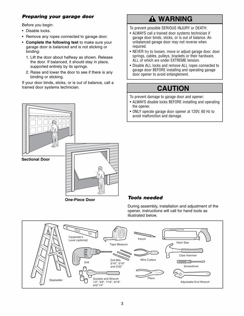
ASSEMBLY STEP 5Tighten the Chain
• Spin the inner nut and lock washer down the trolleythreaded shaft, away from the trolley.
• To tighten the chain, turn outer nut in the directionshown (Figure 1).
• When the chain is approximately 1/4" (6 mm)above the base of the rail at its midpoint, re-tightenthe inner nut to secure the adjustment.
Sprocket noise can result if chain is too loose.
When installation is complete, you may notice somechain droop with the door closed. This is normal. Ifthe chain returns to the position shown in Figure 2when the door is open, do not re-adjust the chain.
NOTE: During future maintenance, ALWAYS pull theemergency release handle to disconnect trolleybefore adjusting chain.
NOTE: You may notice loosening of chain afterAdjustment Step 3 (Test the Safety ReversalSystem). Check for proper tension and readjustchain if necessary. Then repeat Adjustment Step 3.
You have now finished assembling your garagedoor opener. Please read the following warningsbefore proceeding to the installation section.
OuterNut
LockWasher
TrolleyThreadedShaft
Inner Nut
To TightenInner Nut
To Tighten Outer Nut
Base of Rail Mid length of Rail
Chain
1/4" (6 mm)
IMPORTANT INSTALLATION INSTRUCTIONS
To reduce the risk of SEVERE INJURY or DEATH:
WARNING
WARNING
WARNING
1. READ AND FOLLOW ALL INSTALLATION WARNINGSAND INSTRUCTIONS.
2. Install garage door opener ONLY on properly balancedand lubricated garage door. An improperly balanceddoor may not reverse when required and could result inSEVERE INJURY or DEATH.
3. ALL repairs to cables, spring assemblies and otherhardware MUST be made by a trained door systemstechnician BEFORE installing opener.
4. Disable ALL locks and remove ALL ropes connected togarage door BEFORE installing opener to avoidentanglement.
5. Install garage door opener 7 feet (2.13 m) or moreabove floor.
6. Mount emergency release handle 6 feet (1.83 m) abovefloor.
7. NEVER connect garage door opener to power sourceuntil instructed to do so.
8. NEVER wear watches, rings or loose clothing whileinstalling or servicing opener. They could be caught ingarage door or opener mechanisms.
9. Install wall-mounted garage door control:• within sight of the garage door. • out of reach of children at minimum height of 5 feet
(1.5 m).• away from ALL moving parts of the door.
10. Place entrapment warning label on wall next to garagedoor control.
11. Place manual release/safety reverse test label in plainview on inside of garage door.
12. Upon completion of installation, test safety reversalsystem. Door MUST reverse on contact with a 1-1/2" (3.8 cm) high object (or a 2x4 laid flat) on the floor.
Figure 1
Figure 2
12
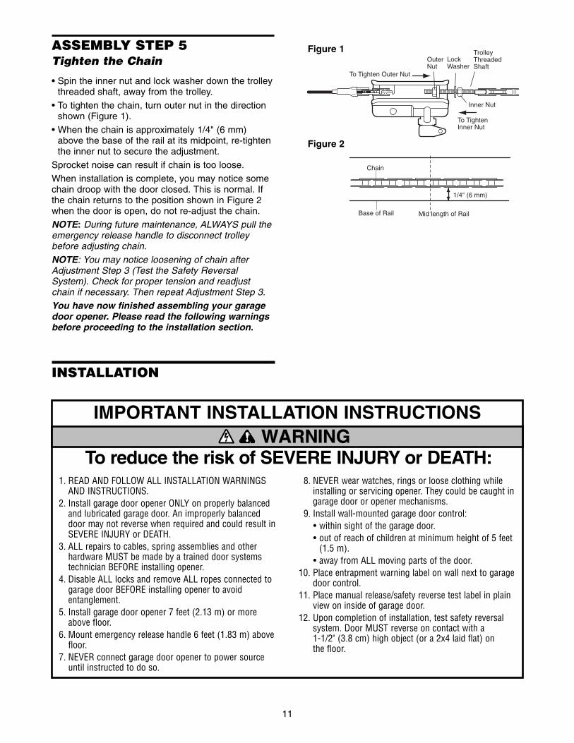
INSTALLATION STEP 1Determine the Header BracketLocation
Installation procedures vary according to garage doortypes. Follow the instructions which apply to yourdoor.
1. Close the door and mark the inside verticalcenterline of the garage door.
2. Extend the line onto the header wall above thedoor.
You can fasten the header bracket within 4 feet(1.22 m) of the left or right of the door centeronly if a torsion spring or center bearing plateis in the way; or you can attach it to the ceiling(see page 13) when clearance is minimal. (Itmay be mounted on the wall upside down ifnecessary, to gain approximately 1/2" (1 cm).If you need to install the header bracket on a 2x4(on wall or ceiling), use lag screws (not provided)to securely fasten the 2x4 to structural supports asshown here and on page 13.
3. Open your door to the highest point of travel asshown. Draw an intersecting horizontal line on theheader wall above the high point:
• 2" (5 cm) above the high point for sectional doorand one-piece door with track.
• 8" (20 cm) above the high point for one-piecedoor without track.
This height will provide travel clearance for the topedge of the door.
NOTE: If the total number of inches exceeds theheight available in your garage, use the maximumheight possible, or refer to page 13 for ceilinginstallation.
Header Wall
Sectional door with curved track
Highest Pointof Travel
Door
3" (7.5 cm)
One-piece door with horizontal track
Door
TrackHeader Wall
Highest Pointof Travel
3" (7.5 cm)Track
Header Wall
Vertical Centerlineof Garage Door
Level(optional)
2x4
2x4
StructuralSupports
OPTIONALCEILINGMOUNTFORHEADERBRACKET
UnfinishedCeiling
Door
Jamb Hardware
One-piece door without track: jamb hardware
8" (20 cm)
Highest Point of Travel Door
Pivot
8" (20 cm)
One-piece door without track: pivot hardware
Highest Point of Travel
Header Wall Header Wall
To prevent possible SERIOUS INJURY or DEATH:• Header bracket MUST be RIGIDLY fastened to
structural support on header wall or ceiling, otherwisegarage door might not reverse when required. DO NOTinstall header bracket over drywall.
• Concrete anchors MUST be used if mounting headerbracket or 2x4 into masonry.
• NEVER try to loosen, move or adjust garage door,springs, cables, pulleys, brackets, or their hardware,ALL of which are under EXTREME tension.
• ALWAYS call a trained door systems technician ifgarage door binds, sticks, or is out of balance. Anunbalanced garage door might not reverse whenrequired.
WARNING
CAUTION WARNING
WARNING

13
Lag Screws5/16"x9x1-5/8"
– Finished Ceiling –
DoorSpring
Header WallUP
Ceiling Mounting Holes
6" (15 cm) Maximum
HeaderBracket
VerticalCenterlineof Garage Door
Garage Door
Vertical Centerlineof Garage Door
INSTALLATION STEP 2Install the Header Bracket
You can attach the header bracket either to the wallabove the garage door, or to the ceiling. Follow theinstructions which will work best for your particularrequirements. Do not install the header bracketover drywall. If installing into masonry, useconcrete anchors (not provided).
WALL HEADER BRACKET INSTALLATION• Center the bracket on the vertical centerline with
the bottom edge of the bracket on the horizontalline as shown (with the arrow pointing toward theceiling).
• Mark the vertical set of bracket holes. Drill 3/16"pilot holes and fasten the bracket securely to astructural support with the hardware provided.
Lag Screw5/16"-9x1-5/8"
HARDWARE SHOWN ACTUAL SIZE
CEILING HEADER BRACKET INSTALLATION• Extend the vertical centerline onto the ceiling as
shown.
• Center the bracket on the vertical mark, no morethan 6" (15 cm) from the wall. Make sure the arrowis pointing away from the wall. The bracket can bemounted flush against the ceiling when clearanceis minimal.
• Mark the side holes. Drill 3/16" pilot holes andfasten bracket securely to a structural support withthe hardware provided.
UP
Wall Mount
Optional Mounting Holes
Lag Screws5/16"x9x1-5/8"
Highest Point of Garage Door Travel
VerticalCenterlineof Garage DoorHeader
Wall
GarageDoor
Door Spring
2x4StructuralSupport
VerticalCenterlineof Garage Door
HeaderBracket
HorizontalLine

14
INSTALLATION STEP 3Attach the Rail to the HeaderBracket
NOTE: (Optional) With some existing installations,you may re-use the old header bracket with the twoplastic spacers included in the hardware bag. Placethe spacers inside the bracket on each side of therail, as illustrated.
• Position the opener on the garage floor below theheader bracket. Use packing material as aprotective base. NOTE: If the door spring is in theway you’ll need help. Have someone hold theopener securely on a temporary support to allowthe rail to clear the spring.
• Position the rail bracket against the headerbracket.
• Align the bracket holes and join with a clevis pin5/16"x1-1/2" as shown.
• Insert a ring fastener to secure.
Opener Carton orTemporarySupport
GarageDoor
OPTION WITHSOME EXISTING INSTALLATIONS
Header Bracket
Idler Pulley
Header Wall
HeaderBracket
Mounting Hole
ExistingHeader Bracket
SpacerMountingHole
ExistingClevis Pin
Clevis Pin 5/16"x1-1/2" Ring Fastener
HARDWARE SHOWN ACTUAL SIZE
15
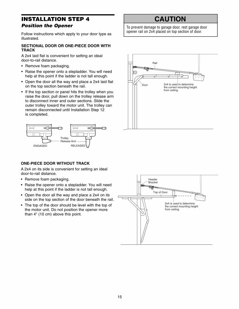
ONE-PIECE DOOR WITHOUT TRACKA 2x4 on its side is convenient for setting an idealdoor-to-rail distance.
• Remove foam packaging.
• Raise the opener onto a stepladder. You will needhelp at this point if the ladder is not tall enough.
• Open the door all the way and place a 2x4 on itsside on the top section of the door beneath the rail.
• The top of the door should be level with the top ofthe motor unit. Do not position the opener morethan 4" (10 cm) above this point.
INSTALLATION STEP 4Position the Opener
Follow instructions which apply to your door type asillustrated.
SECTIONAL DOOR OR ONE-PIECE DOOR WITHTRACKA 2x4 laid flat is convenient for setting an ideal door-to-rail distance.
• Remove foam packaging.
• Raise the opener onto a stepladder. You will needhelp at this point if the ladder is not tall enough.
• Open the door all the way and place a 2x4 laid flaton the top section beneath the rail.
• If the top section or panel hits the trolley when youraise the door, pull down on the trolley release armto disconnect inner and outer sections. Slide theouter trolley toward the motor unit. The trolley canremain disconnected until Installation Step 12is completed.
To prevent damage to garage door, rest garage dooropener rail on 2x4 placed on top section of door.
WARNING
CAUTION WARNING
WARNING
HeaderBracket
Top of Door
2x4 is used to determine the correct mounting height from ceiling.
Rail
2x4 is used to determine the correct mounting height from ceiling.
Door
ENGAGED RELEASED
TrolleyRelease Arm
16
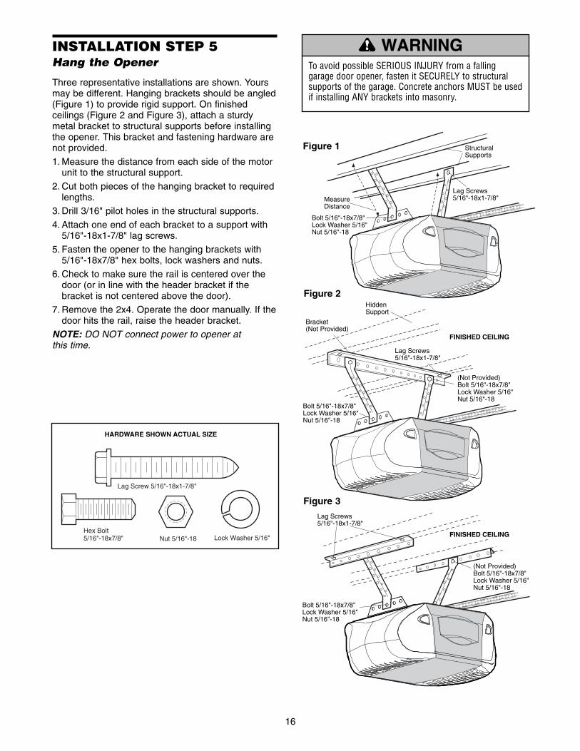
INSTALLATION STEP 5Hang the Opener
Three representative installations are shown. Yoursmay be different. Hanging brackets should be angled(Figure 1) to provide rigid support. On finishedceilings (Figure 2 and Figure 3), attach a sturdymetal bracket to structural supports before installingthe opener. This bracket and fastening hardware arenot provided.
1. Measure the distance from each side of the motorunit to the structural support.
2. Cut both pieces of the hanging bracket to requiredlengths.
3. Drill 3/16" pilot holes in the structural supports.
4. Attach one end of each bracket to a support with5/16"-18x1-7/8" lag screws.
5. Fasten the opener to the hanging brackets with5/16"-18x7/8" hex bolts, lock washers and nuts.
6. Check to make sure the rail is centered over thedoor (or in line with the header bracket if thebracket is not centered above the door).
7. Remove the 2x4. Operate the door manually. If thedoor hits the rail, raise the header bracket.
NOTE: DO NOT connect power to opener at this time.
To avoid possible SERIOUS INJURY from a fallinggarage door opener, fasten it SECURELY to structuralsupports of the garage. Concrete anchors MUST be usedif installing ANY brackets into masonry.
Lag Screw 5/16"-18x1-7/8"
Hex Bolt5/16"-18x7/8" Nut 5/16"-18 Lock Washer 5/16"
HARDWARE SHOWN ACTUAL SIZE
MeasureDistance
Lag Screws5/16"-18x1-7/8"
StructuralSupports
Bracket(Not Provided)
Lag Screws5/16"-18x1-7/8"
(Not Provided)Bolt 5/16"-18x7/8" Lock Washer 5/16" Nut 5/16"-18
FINISHED CEILING
Hidden Support
Bolt 5/16"-18x7/8" Lock Washer 5/16" Nut 5/16"-18
Bolt 5/16"-18x7/8" Lock Washer 5/16" Nut 5/16"-18
Lag Screws5/16"-18x1-7/8"
(Not Provided)Bolt 5/16"-18x7/8" Lock Washer 5/16" Nut 5/16"-18
FINISHED CEILING
Bolt 5/16"-18x7/8" Lock Washer 5/16" Nut 5/16"-18
Figure 1
Figure 2
WARNING
CAUTION WARNING
WARNING
Figure 3
To prevent possible SERIOUS INJURY or DEATH fromelectrocution:• Be sure power is not connected BEFORE installing door
control.• Connect ONLY to 24 VOLT low voltage wires. To prevent possible SERIOUS INJURY or DEATH from aclosing garage door:• Install door control within sight of garage door, out of
reach of children at a minimum height of 5 feet (1.5 m), and away from ALL moving parts of door.
• NEVER permit children to operate or play with doorcontrol push buttons or remote control transmitters.
• Activate door ONLY when it can be seen clearly, isproperly adjusted, and there are no obstructions to doortravel.
• ALWAYS keep garage door in sight until completelyclosed. NEVER permit anyone to cross path of closinggarage door.
WARNING
CAUTION WARNING
WARNING
KG
1
3
9
7
5
KG
1
3
9
7
5
To release wire, pushwith screwdriver tip
Door ControlConnections
7/16" (11 mm)
Strip wire 7/16" (11 mm)
Red GreyWhite
LOCK
LIGHT
To ReplaceInsert TopTabs First
STANDARD WALL MOUNT
DetectorSwitchPush Bar Cover
ONOFF
Figure 1
1RED
2WHITE
DoorControlTerminalScrews
24 VoltBell Wire
Back View
Bottom MountingHole
Top Mounting Hole
Figure 3
Drywall Anchors
InsulatedStaples
Screw 6ABx1-1/4"(standard installation)
Screw 6-32x1" (pre-wired)
HARDWARE SHOWN ACTUAL SIZE
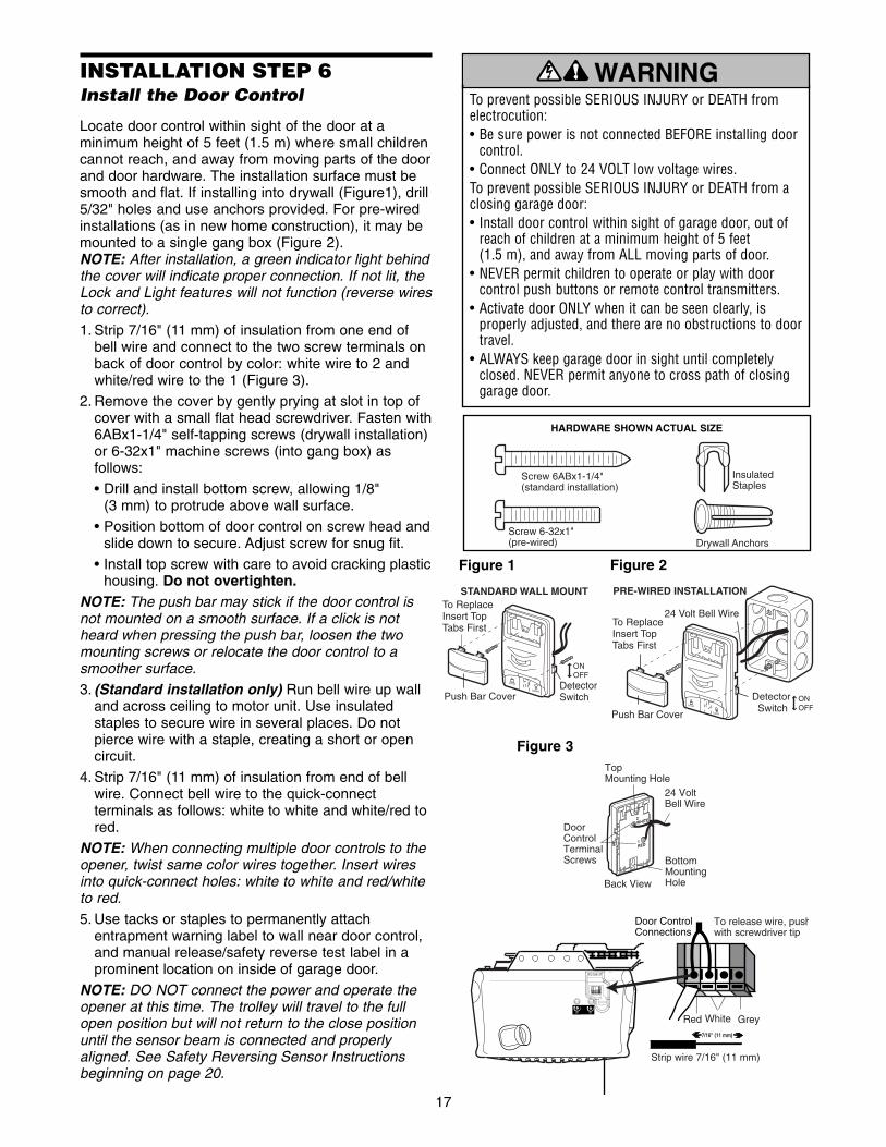
INSTALLATION STEP 6Install the Door Control
Locate door control within sight of the door at aminimum height of 5 feet (1.5 m) where small childrencannot reach, and away from moving parts of the doorand door hardware. The installation surface must besmooth and flat. If installing into drywall (Figure1), drill5/32" holes and use anchors provided. For pre-wiredinstallations (as in new home construction), it may bemounted to a single gang box (Figure 2). NOTE: After installation, a green indicator light behindthe cover will indicate proper connection. If not lit, theLock and Light features will not function (reverse wiresto correct).
1. Strip 7/16" (11 mm) of insulation from one end ofbell wire and connect to the two screw terminals onback of door control by color: white wire to 2 andwhite/red wire to the 1 (Figure 3).
2. Remove the cover by gently prying at slot in top ofcover with a small flat head screwdriver. Fasten with6ABx1-1/4" self-tapping screws (drywall installation)or 6-32x1" machine screws (into gang box) asfollows:
• Drill and install bottom screw, allowing 1/8" (3 mm) to protrude above wall surface.
• Position bottom of door control on screw head andslide down to secure. Adjust screw for snug fit.
• Install top screw with care to avoid cracking plastichousing. Do not overtighten.
NOTE: The push bar may stick if the door control isnot mounted on a smooth surface. If a click is notheard when pressing the push bar, loosen the twomounting screws or relocate the door control to asmoother surface.
3. (Standard installation only) Run bell wire up walland across ceiling to motor unit. Use insulatedstaples to secure wire in several places. Do notpierce wire with a staple, creating a short or opencircuit.
4. Strip 7/16" (11 mm) of insulation from end of bellwire. Connect bell wire to the quick-connectterminals as follows: white to white and white/red tored.
NOTE: When connecting multiple door controls to theopener, twist same color wires together. Insert wiresinto quick-connect holes: white to white and red/whiteto red.
5. Use tacks or staples to permanently attachentrapment warning label to wall near door control,and manual release/safety reverse test label in aprominent location on inside of garage door.
NOTE: DO NOT connect the power and operate theopener at this time. The trolley will travel to the fullopen position but will not return to the close positionuntil the sensor beam is connected and properlyaligned. See Safety Reversing Sensor Instructionsbeginning on page 20.
17
Figure 2
24 Volt Bell Wire
PRE-WIRED INSTALLATION
LOCK
LIGHT
To ReplaceInsert TopTabs First
Detector Switch
Push Bar Cover
ONOFF

18
INSTALLATION STEP 7Install the Lights
• Install a 100 watt maximum light bulb in eachsocket. Light bulb size should be A19, standardneck only. The lights will turn ON and remain lit forapproximately 4-1/2 minutes when power isconnected. Then the lights will turn OFF.
• Insert bottom lens tabs into slots on chassis. Tilttowards chassis to engage top tabs, then dropdown gently into place (see illustration).
• To remove, depress both top lens tabs. Tilt lensslightly outward and down, then pull out to clearbulbs. Use care to avoid snapping off bottom lenstabs.
• Use A19, standard neck garage door opener bulbsfor replacement.
NOTE: Use only standard light bulbs. The use ofshort neck or speciality light bulbs may overheat theendpanel or light socket.
INSTALLATION STEP 8Attach the Emergency ReleaseRope and Handle
• Thread one end of the rope through the hole in thetop of the red handle so “NOTICE” reads right sideup as shown. Secure with an overhand knot atleast 1" (2.5 cm) from the end of the rope toprevent slipping.
• Thread the other end of the rope through the holein the release arm of the outer trolley.
• Adjust rope length so the handle is 6 feet (1.83 m)above the floor. Ensure that the rope and handleclear the tops of all vehicles to avoidentanglement. Secure with an overhand knot.
NOTE: If it is necessary to cut the rope, heat sealthe cut end with a match or lighter to preventunraveling.
To prevent possible SERIOUS INJURY or DEATH from afalling garage door:• If possible, use emergency release handle to disengage
trolley ONLY when garage door is CLOSED. Weak orbroken springs or unbalanced door could result in anopen door falling rapidly and/or unexpectedly.
• NEVER use emergency release handle unless garagedoorway is clear of persons and obstructions.
• NEVER use handle to pull door open or closed. If ropeknot becomes untied, you could fall.
LensHinge
100 Watt (Max)Standard Light Bulb
Release Tab
100 Watt (Max)Standard Light Bulb
TrolleyRelease arm
NOTICEEmergencyRelease Handle
OverhandKnot
Trolley
WARNING
CAUTION WARNING
WARNING
To prevent possible OVERHEATING of the endpanel orlight socket: • DO NOT use short neck or specialty light bulbs.• DO NOT use halogen bulbs. Use ONLY incandescent.To prevent damage to the opener: • DO NOT use bulbs larger than 100W.• ONLY use A19 size bulbs.
WARNING
CAUTION WARNING
WARNING
19
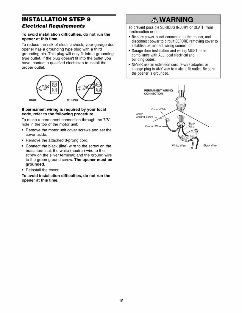
INSTALLATION STEP 9Electrical Requirements
To avoid installation difficulties, do not run theopener at this time.To reduce the risk of electric shock, your garage dooropener has a grounding type plug with a thirdgrounding pin. This plug will only fit into a groundingtype outlet. If the plug doesn't fit into the outlet youhave, contact a qualified electrician to install theproper outlet.
If permanent wiring is required by your localcode, refer to the following procedure.To make a permanent connection through the 7/8"hole in the top of the motor unit:
• Remove the motor unit cover screws and set thecover aside.
• Remove the attached 3-prong cord.
• Connect the black (line) wire to the screw on thebrass terminal; the white (neutral) wire to thescrew on the silver terminal; and the ground wireto the green ground screw. The opener must begrounded.
• Reinstall the cover.
To avoid installation difficulties, do not run theopener at this time.
RIGHT WRONG
To prevent possible SERIOUS INJURY or DEATH fromelectrocution or fire:• Be sure power is not connected to the opener, and
disconnect power to circuit BEFORE removing cover toestablish permanent wiring connection.
• Garage door installation and wiring MUST be incompliance with ALL local electrical and building codes.
• NEVER use an extension cord, 2-wire adapter, orchange plug in ANY way to make it fit outlet. Be surethe opener is grounded.
Ground Tab
Green Ground Screw
Ground Wire
Black Wire
PERMANENT WIRINGCONNECTION
White Wire
BlackWire
WARNING
CAUTION WARNING
WARNING

20
Invisible Light BeamProtection Area
Safety Reversing Sensor6" (15 cm) max. above floor
Safety Reversing Sensor6" (15 cm) max. above floor
Facing the door from inside the garage
INSTALLATION STEP 10Install The Protector System®
The safety reversing sensor must be connectedand aligned correctly before the garage dooropener will move in the down direction.
IMPORTANT INFORMATION ABOUT THE SAFETY REVERSING SENSORWhen properly connected and aligned, the sensorwill detect an obstacle in the path of its electronicbeam. The sending eye (with an amber indicatorlight) transmits an invisible light beam to thereceiving eye (with a green indicator light). If anobstruction breaks the light beam while the door isclosing, the door will stop and reverse to full openposition, and the opener lights will flash 10 times.
The units must be installed inside the garage so thatthe sending and receiving eyes face each otheracross the door, no more than 6" (15 cm) above thefloor. Either can be installed on the left or right of thedoor as long as the sun never shines directly into thereceiving eye lens.
The mounting brackets are designed to clip onto thetrack of sectional garage doors without additionalhardware.
If it is necessary to mount the units on the wall, thebrackets must be securely fastened to a solidsurface such as the wall framing. Extension brackets(see accessories) are available if needed. Ifinstalling in masonry construction, add a piece ofwood at each location to avoid drilling extra holes inmasonry if repositioning is necessary.
The invisible light beam path must be unobstructed.No part of the garage door (or door tracks, springs,hinges, rollers or other hardware) may interrupt thebeam while the door is closing.
Be sure power is not connected to the garage dooropener BEFORE installing the safety reversing sensor.To prevent SERIOUS INJURY or DEATH from a closinggarage door:• Correctly connect and align the safety reversing
sensor. This required safety device MUST NOT bedisabled.
• Install the safety reversing sensor so beam is NOHIGHER than 6" (15 cm) above garage floor.
WARNING
CAUTION WARNING
WARNING

21
DOOR TRACK MOUNT (RIGHT SIDE)
IndicatorLight
Lens
Lip
SensorBracket
DoorTrack
FLOOR MOUNT (RIGHT SIDE)
WALL MOUNT (RIGHT SIDE)
IndicatorLight
SensorBracket
Lens
ExtensionBracket(See Accessories)
Inside
Garage
Wall
(Provided withExtension Bracket)
(Provided withExtension Bracket)
Figure 1
Figure 2
Figure 3
Figure 4
WALL MOUNT (RIGHT SIDE)
Attach with Concrete Anchors(Not Provided)
Inside
Garage
Wall
SensorBracket
LensIndicatorLight
Inside
Garage
Wall
IndicatorLight Sensor
Bracket
Lens
Lag Screws(Not Provided)
Fasten Wood Block to Wall withLag Screws (Not Provided)
INSTALLING THE BRACKETSBe sure power to the opener is disconnected.Install and align the brackets so the sensors will faceeach other across the garage door, with the beam nohigher than 6" (15 cm) above the floor. They may beinstalled in one of three ways, as follows.
Garage door track installation (preferred):• Slip the curved arms over the rounded edge of
each door track, with the curved arms facing thedoor. Snap into place against the side of the track.It should lie flush, with the lip hugging the backedge of the track, as shown in Figure 1.
If your door track will not support the bracketsecurely, wall installation is recommended.
Wall installation (Figure 2 & 3): • Place the bracket against the wall with curved
arms facing the door. Be sure there is enoughclearance for the sensor beam to be unobstructed.
• If additional depth is needed, an extension bracket(See Accessories) or wood blocks can be used.
• Use bracket mounting holes as a template tolocate and drill (2) 3/16" diameter pilot holes onthe wall at each side of the door, no higher than 6"(15 cm) above the floor.
• Attach brackets to wall with lag screws(Not provided).
• If using extension brackets or wood blocks, adjustright and left assemblies to the same distance outfrom the mounting surface. Make sure all doorhardware obstructions are cleared.
Floor installation (Figure 4): • Use wood blocks or extension brackets (See
Accessories) to elevate sensor brackets so thelenses will be no higher than 6" (15 cm) above thefloor.
• Carefully measure and place right and leftassemblies at the same distance out from the wall.Be sure all door hardware obstructions arecleared.
• Fasten to the floor with concrete anchors asshown.
Wing Nut1/4"-20
StaplesCarriage Bolt1/4"-20x1/2"
HARDWARE SHOWN ACTUAL SIZE
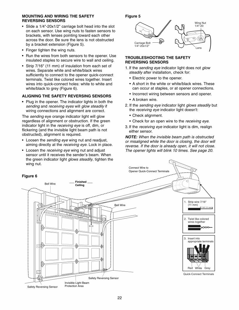
22
Carriage Bolt 1/4"-20x1/2"
Lens
Wing Nut1/4"-20
Figure 5MOUNTING AND WIRING THE SAFETYREVERSING SENSORS• Slide a 1/4"-20x1/2" carriage bolt head into the slot
on each sensor. Use wing nuts to fasten sensors tobrackets, with lenses pointing toward each otheracross the door. Be sure the lens is not obstructedby a bracket extension (Figure 5).
• Finger tighten the wing nuts.
• Run the wires from both sensors to the opener. Useinsulated staples to secure wire to wall and ceiling.
• Strip 7/16" (11 mm) of insulation from each set ofwires. Separate white and white/black wiressufficiently to connect to the opener quick-connectterminals. Twist like colored wires together. Insertwires into quick-connect holes: white to white andwhite/black to grey (Figure 6).
ALIGNING THE SAFETY REVERSING SENSORS• Plug in the opener. The indicator lights in both the
sending and receiving eyes will glow steadily ifwiring connections and alignment are correct.
The sending eye orange indicator light will glowregardless of alignment or obstruction. If the greenindicator light in the receiving eye is off, dim, orflickering (and the invisible light beam path is notobstructed), alignment is required.
• Loosen the sending eye wing nut and readjust,aiming directly at the receiving eye. Lock in place.
• Loosen the receiving eye wing nut and adjustsensor until it receives the sender’s beam. Whenthe green indicator light glows steadily, tighten thewing nut.
TROUBLESHOOTING THE SAFETYREVERSING SENSORS1. If the sending eye indicator light does not glow
steadily after installation, check for:
• Electric power to the opener.
• A short in the white or white/black wires. Thesecan occur at staples, or at opener connections.
• Incorrect wiring between sensors and opener.
• A broken wire.
2. If the sending eye indicator light glows steadily butthe receiving eye indicator light doesn't:
• Check alignment.
• Check for an open wire to the receiving eye.
3. If the receiving eye indicator light is dim, realigneither sensor.
NOTE: When the invisible beam path is obstructedor misaligned while the door is closing, the door willreverse. If the door is already open, it will not close.The opener lights will blink 10 times. See page 20.
Invisible Light BeamProtection AreaSafety Reversing Sensor
Safety Reversing Sensor
Connect Wire toOpener Quick-Connect Terminals
Bell Wire
Bell WireFinishedCeiling
Quick-Connect Terminals
3. Insert into appropriate terminals
1. Strip wire 7/16" (11 mm)
2. Twist like colored wires together
7/16" (11 mm)
Red GreyWhite
Figure 6

23
Fiberglass, aluminum or lightweight steel garage doorsWILL REQUIRE reinforcement BEFORE installation ofdoor bracket. Contact your door manufacturer forreinforcement kit.
WARNING
CAUTION WARNING
WARNING
INSTALLATION STEP 11Fasten the Door Bracket
Follow instructions which apply to your door typeas illustrated below or on the following page.
A horizontal reinforcement brace should be longenough to be secured to two or three verticalsupports. A vertical reinforcement brace shouldcover the height of the top panel. Figure 1 shows one piece of angle iron as thehorizontal brace. For the vertical brace, 2 pieces ofangle iron are used to create a U-shaped support.The best solution is to check with your garage doormanufacturer for an opener installation doorreinforcement kit.
NOTE: Many door reinforcement kits provide fordirect attachment of the clevis pin and door arm. Inthis case you will not need the door bracket; proceedto Step 12.
SECTIONAL DOORS1. Center the door bracket on the previously marked
vertical centerline used for the header bracketinstallation. Note correct UP placement, asstamped inside the bracket.
2. Position the top edge of the bracket 2"-4" (5-10 cm) below the top edge of the door, ORdirectly below any structural support across the topof the door.
3. Mark, drill holes and install as follows, dependingon your door’s construction:
Metal or light weight doors using a vertical angleiron brace between the door panel support andthe door bracket: • Drill 3/16" fastening holes. Secure the door bracket
using the two 1/4"-14x5/8" self-threading screws.(Figure 2A)
• Alternately, use two 5/16" bolts, lock washers andnuts (not provided). (Figure 2B)
Metal, insulated or light weight factory reinforceddoors: • Drill 3/16" fastening holes. Secure the door bracket
using the self-threading screws (Figure 3).
Wood Doors:• Use top and bottom or side to side door bracket
holes. Drill 5/16" holes through the door andsecure bracket with 5/16"x2" carriage bolts, lockwashers and nuts (not provided). (Figure 4)
NOTE: The 1/4"-14x5/8"self-threading screwsare not intended for useon wood doors.
VerticalCenterlineof Garage Door
DoorBracketLocation
HeaderBracket
HORIZONTAL AND VERTICAL REINFORCEMENT IS NEEDED FOR LIGHTWEIGHT GARAGE DOORS (FIBERGLASS, ALUMINUM, STEEL, DOORS WITH GLASS PANEL, ETC.). (NOT PROVIDED)
DoorBracket
VerticalCenterline of Garage Door
UP
VerticalReinforcement
Self-ThreadingScrew1/4"-14x5/8"
Self-ThreadingScrew1/4"-14x5/8"
DoorBracket
Nut5/16"-18
Bolt5/16"-18x2"
Lock Washer5/16"
UP
VerticalReinforcement
(Not Provided)VerticalCenterline of Garage Door
UP
Self-Threading Screw 1/4"-14x5/8"
Vertical Centerline of Garage Door
UP
Inside Edge of Door or Reinforcement Board
Bolt 5/16"x2"
(Not Provided)
Vertical Centerline of Garage Door
Figure 1
Figure 2A
Figure 3
Figure 4
Figure 2B
HARDWARESHOWNACTUAL SIZE

24
Header Wall
VerticalCenterline ofGarage Door
Finished Ceiling
OptionalPlacementof DoorBracket
HeaderBracket
DoorBracket
2x4 Support
For a door with no exposed framing,or for the optional installation, use lag screws 5/16"x1-1/2" (Not Provided)to fasten door bracket.
METAL DOOR
Top of Door(Inside Garage)
DoorBracket
OptionalPlacement
Top Edgeof Door
Self-Threading Screw 1/4"-14x5/8"
DoorBracket
Top of Door(Inside Garage)
Carriage Bolt5/16"x2"(Not Provided)
OptionalPlacement
Lock Washer5/16"
Nut5/16"-18
Top Edgeof Door
WOOD DOOR
HORIZONTAL AND VERTICAL REINFORCEMENT IS NEEDED FOR LIGHTWEIGHT GARAGE DOORS (FIBERGLASS, ALUMINUM, STEEL, DOORS WITH GLASS PANEL, ETC.). (NOT PROVIDED)
ONE-PIECE DOORS Please read and comply with the warnings andreinforcement instructions on the previous page.They apply to one-piece doors also.
• Center the door bracket on the top of the door, inline with the header bracket as shown. Mark eitherthe left and right, or the top and bottom holes.
• Metal Doors: Drill 3/16" pilot holes and fasten thebracket with the 1/4"-14x5/8" self-threading screwsprovided.
• Wood Doors: Drill 5/16" holes and use 5/16"x2"carriage bolts, lock washers and nuts (notprovided) or 5/16"x1-1/2" lag screws (not provided)depending on your installation needs.
NOTE: The door bracket may be installed on the topedge of the door if required for your installation.(Refer to the dotted line optional placement drawing.)
Self-Threading Screw1/4"-14x5/8"
HARDWARE SHOWNACTUAL SIZE
25
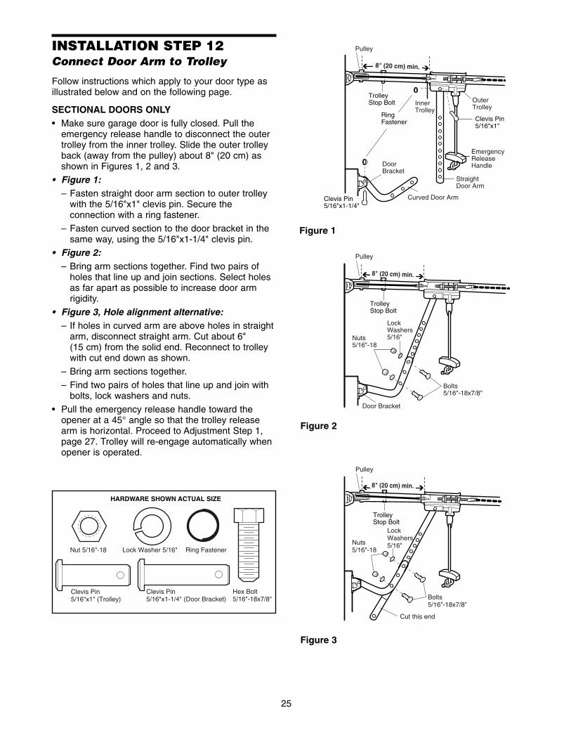
INSTALLATION STEP 12Connect Door Arm to Trolley
Follow instructions which apply to your door type asillustrated below and on the following page.
SECTIONAL DOORS ONLY• Make sure garage door is fully closed. Pull the
emergency release handle to disconnect the outertrolley from the inner trolley. Slide the outer trolleyback (away from the pulley) about 8" (20 cm) asshown in Figures 1, 2 and 3.
• Figure 1:– Fasten straight door arm section to outer trolley
with the 5/16"x1" clevis pin. Secure theconnection with a ring fastener.
– Fasten curved section to the door bracket in thesame way, using the 5/16"x1-1/4" clevis pin.
• Figure 2:– Bring arm sections together. Find two pairs of
holes that line up and join sections. Select holesas far apart as possible to increase door armrigidity.
• Figure 3, Hole alignment alternative:– If holes in curved arm are above holes in straight
arm, disconnect straight arm. Cut about 6" (15 cm) from the solid end. Reconnect to trolleywith cut end down as shown.
– Bring arm sections together.
– Find two pairs of holes that line up and join withbolts, lock washers and nuts.
• Pull the emergency release handle toward theopener at a 45° angle so that the trolley releasearm is horizontal. Proceed to Adjustment Step 1,page 27. Trolley will re-engage automatically whenopener is operated.
Trolley Stop Bolt
8" (20 cm) min.
8" (20 cm) min.
Trolley Stop Bolt
Trolley Stop Bolt
Ring Fastener
DoorBracket
StraightDoor Arm
Curved Door Arm
InnerTrolley
OuterTrolley
LockWashers5/16"Nuts
5/16"-18
Door Bracket
Bolts5/16"-18x7/8"
Cut this end
EmergencyReleaseHandle
LockWashers5/16"Nuts
5/16"-18
Bolts5/16"-18x7/8"
Clevis Pin5/16"x1"
Clevis Pin5/16"x1-1/4"
Pulley
Pulley
Pulley
8" (20 cm) min.
Figure 1
Figure 2
Figure 3
Lock Washer 5/16"Nut 5/16"-18 Ring Fastener
Hex Bolt5/16"-18x7/8"
Clevis Pin5/16"x1" (Trolley)
Clevis Pin5/16"x1-1/4" (Door Bracket)
HARDWARE SHOWN ACTUAL SIZE

26
ALL ONE-PIECE DOORS1. Assemble the door arm, Figure 4:
• Fasten the straight and curved door arm sectionstogether to the longest possible length (with a 2or 3 hole overlap).
• With the door closed, connect the straight doorarm section to the door bracket with the5/16"x1-1/4" clevis pin.
• Secure with a ring fastener.
2. Adjustment procedures, Figure 5:• On one-piece doors, before connecting the door
arm to the trolley, the travel limits must beadjusted. Limit adjustment screws are located onthe left side panel as shown on page 27. Followadjustment procedures below.
• Open door adjustment: decrease UPtravel limit
- Turn the UP limit adjustment screw counter-clockwise 4 turns.
- Press the Door Control push button. The trolleywill travel to the fully open position.
- Manually raise the door to the open position(parallel to the floor), and lift the door arm to thetrolley. The arm should touch the trolley just inback of the door arm connector hole. Refer tothe fully open trolley/door arm positions in theillustration. If the arm does not extend farenough, adjust the limit further. One full turnequals 3" (7.5 cm) of trolley travel.
• Closed door adjustment: decrease DOWNtravel limit
- Turn the DOWN limit adjustment screwclockwise 4 complete turns.
Nuts 5/16"-18 Lock
Washers 5/16"
Ring Fastener
Straight Arm
Bolts 5/16"-18x7/8"
Door Bracket
Clevis Pin 5/16"x1-1/4"
Curved Door Arm
- Press the Door Control push button. The trolleywill travel to the fully closed position.
- Manually close the door and lift the door arm tothe trolley. The arm should touch the trolley justahead of the door arm connector hole. Refer tothe fully closed trolley/door arm positions in theillustration. If the arm is behind the connectorhole, adjust the limit further. One full turn equals3" (7.5 cm) of trolley travel.
3. Connect the door arm to the trolley:• Close the door and join the curved arm to the
connector hole in the trolley with the remainingclevis pin. It may be necessary to lift the doorslightly to make the connection.
• Secure with a ring fastener.
• Run the opener through a complete travel cycle.If the door has a slight “backward” slant in fullopen position as shown in the illustration,decrease the UP limit until the door is parallel to the floor.
NOTE: When setting the up limit on the followingpage, the door should not have a “backward” slantwhen fully open as illustrated below. A slightbackward slant will cause unnecessary buckingand/or jerking operation as the door is being openedor closed from the fully open position.
Figure 4
Door Arm
Closed Door
Outer Trolley
Emergency Release Handle
Open Door
Door with Backward Slant (Incorrect)
Correct Angle
Inner Trolley
Inner Trolley
Outer Trolley
Figure 5

27
ADJUSTMENT STEP 1Adjust the UP and DOWN TravelLimits
Limit adjustment settings regulate the points at whichthe door will stop when moving up or down.
To operate the opener, press the Door Control pushbar. Run the opener through a complete travel cycle.
• Does the door open and close completely?
• Does the door stay closed and not reverseunintentionally when fully closed?
If your door passes both of these tests, no limitadjustments are necessary unless the reversing testfails (Adjustment Step 3, page 29).
Adjustment procedures are outlined below. Read theprocedures carefully before proceeding toAdjustment Step 2. Use a screwdriver to make limitadjustments. Run the opener through a completetravel cycle after each adjustment. NOTE: Repeated operation of the opener duringadjustment procedures may cause the motor tooverheat and shut off. Simply wait 15 minutes andtry again.
NOTE: If anything interferes with the door’s upwardtravel, it will stop. If anything interferes with thedoor’s downward travel (including binding orunbalanced doors), it will reverse.
HOW AND WHEN TO ADJUST THE LIMITS
• If the door does not open completely but opensat least five feet (1.5 m):Increase up travel. Turn the UP limit adjustmentscrew clockwise. One turn equals 3" (7.5 cm) oftravel.
NOTE: To prevent the trolley from hitting the coverprotection bolt, keep a minimum distance of 2-4" (5 cm - 10 cm) between the trolley and the bolt.
• If door does not open at least 5 feet (1.5 m): Adjust the UP (open) force as explained inAdjustment Step 2.
• If the door does not close completely:Increase down travel. Turn the down limitadjustment screw counterclockwise. One turnequals 3" (7.5 cm) of travel.
If door still won't close completely and the trolleybumps into the pulley bracket (page 4), trylengthening the door arm (page 25) anddecreasing the down limit.
• If the opener reverses in fully closed position:Decrease down travel. Turn the down limitadjustment screw clockwise. One turn equals 3" (7.5 cm) of travel.
Without a properly installed safety reversal system,persons (particularly small children) could beSERIOUSLY INJURED or KILLED by a closing garagedoor.• Incorrect adjustment of garage door travel limits will
interfere with proper operation of safety reversalsystem.
• If one control (force or travel limits) is adjusted, theother control may also need adjustment.
• After ANY adjustments are made, the safety reversalsystem MUST be tested. Door MUST reverse oncontact with 1-1/2" high (3.8 cm) object (or 2x4 laidflat) on floor.
• If the door reverses when closing and there isno visible interference to travel cycle:If the opener lights are flashing, the SafetyReversing Sensors are either not installed,misaligned, or obstructed. See Troubleshooting,page 22.
Test the door for binding: Pull the emergencyrelease handle. Manually open and close the door.If the door is binding or unbalanced, call for atrained door systems technician. If the door isbalanced and not binding, adjust the DOWN(close) force. See Adjustment Step 2.
ADJUSTMENT LABEL
Left Panel
Cover Protection Bolt
2-4"
Limit Adjustment Screws
(5-10 cm)
WARNING
CAUTION WARNING
WARNING
To prevent damage to vehicles, be sure fully open doorprovides adequate clearance.
WARNING
CAUTION WARNING
WARNING
28
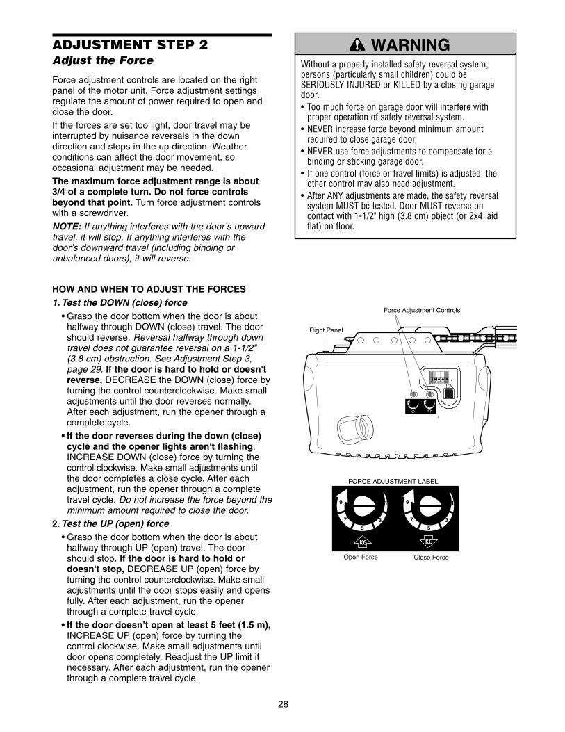
ADJUSTMENT STEP 2Adjust the Force
Force adjustment controls are located on the rightpanel of the motor unit. Force adjustment settingsregulate the amount of power required to open andclose the door.
If the forces are set too light, door travel may beinterrupted by nuisance reversals in the downdirection and stops in the up direction. Weatherconditions can affect the door movement, sooccasional adjustment may be needed.
The maximum force adjustment range is about3/4 of a complete turn. Do not force controlsbeyond that point. Turn force adjustment controlswith a screwdriver.
NOTE: If anything interferes with the door’s upwardtravel, it will stop. If anything interferes with thedoor’s downward travel (including binding orunbalanced doors), it will reverse.
HOW AND WHEN TO ADJUST THE FORCES1. Test the DOWN (close) force
• Grasp the door bottom when the door is abouthalfway through DOWN (close) travel. The doorshould reverse. Reversal halfway through downtravel does not guarantee reversal on a 1-1/2"(3.8 cm) obstruction. See Adjustment Step 3,page 29. If the door is hard to hold or doesn'treverse, DECREASE the DOWN (close) force byturning the control counterclockwise. Make smalladjustments until the door reverses normally.After each adjustment, run the opener through acomplete cycle.
• If the door reverses during the down (close)cycle and the opener lights aren't flashing,INCREASE DOWN (close) force by turning thecontrol clockwise. Make small adjustments untilthe door completes a close cycle. After eachadjustment, run the opener through a completetravel cycle. Do not increase the force beyond theminimum amount required to close the door.
2. Test the UP (open) force• Grasp the door bottom when the door is about
halfway through UP (open) travel. The doorshould stop. If the door is hard to hold ordoesn't stop, DECREASE UP (open) force byturning the control counterclockwise. Make smalladjustments until the door stops easily and opensfully. After each adjustment, run the openerthrough a complete travel cycle.
• If the door doesn’t open at least 5 feet (1.5 m),INCREASE UP (open) force by turning thecontrol clockwise. Make small adjustments untildoor opens completely. Readjust the UP limit ifnecessary. After each adjustment, run the openerthrough a complete travel cycle.
Right Panel
Force Adjustment Controls
1
3
9
7
5
1
3
9
7
5
FORCE ADJUSTMENT LABEL
Open Force Close Force
Without a properly installed safety reversal system,persons (particularly small children) could beSERIOUSLY INJURED or KILLED by a closing garagedoor.• Too much force on garage door will interfere with
proper operation of safety reversal system.• NEVER increase force beyond minimum amount
required to close garage door. • NEVER use force adjustments to compensate for a
binding or sticking garage door.• If one control (force or travel limits) is adjusted, the
other control may also need adjustment.• After ANY adjustments are made, the safety reversal
system MUST be tested. Door MUST reverse oncontact with 1-1/2" high (3.8 cm) object (or 2x4 laidflat) on floor.
WARNING
CAUTION WARNING
WARNING

29
Without a properly installed safety reversal system,persons (particularly small children) could beSERIOUSLY INJURED or KILLED by a closing garagedoor. • Safety reversal system MUST be tested every month.• If one control (force or travel limits) is adjusted, the
other control may also need adjustment.• After ANY adjustments are made, the safety reversal
system MUST be tested. Door MUST reverse oncontact with 1-1/2" high (3.8 cm) object (or 2x4 laidflat) on the floor.
ADJUSTMENT STEP 3Test the Safety Reversal System
TEST• With the door fully open, place a 1-1/2" (3.8 cm)
board (or a 2x4 laid flat) on the floor, centeredunder the garage door.
• Operate the door in the down direction. The doormust reverse on striking the obstruction.
ADJUST• If the door stops on the obstruction, it is not
traveling far enough in the down direction.Increase the DOWN limit by turning the DOWNlimit adjustment screw counterclockwise 1/4 turn.
NOTE: On a sectional door, make sure limitadjustments do not force the door arm beyond astraight up and down position. See the illustrationon page 25.
• Repeat the test.
• When the door reverses on the 1-1/2" (3.8 cm)board, remove the obstruction and run the openerthrough 3 or 4 complete travel cycles to testadjustment.
• If the unit continues to fail the Safety Reverse Test,call for a trained door systems technician.
IMPORTANT SAFETY CHECK:Test the Safety Reverse System after:
• Each adjustment of door arm length, limits, orforce controls.
• Any repair to or adjustment of the garage door(including springs and hardware).
• Any repair to or buckling of the garage floor.
• Any repair to or adjustment of the opener.
ADJUSTMENT STEP 4Test The Protector System®
• Press the remote control push button to open thedoor.
• Place the opener carton in the path of the door.
• Press the remote control push button to close thedoor. The door will not move more than an inch(2.5 cm), and the opener lights will flash.
The garage door opener will not close from a remoteif the indicator light in either sensor is off (alertingyou to the fact that the sensor is misaligned orobstructed).
If the opener closes the door when the safetyreversing sensor is obstructed (and the sensorsare no more than 6" (15 cm) above the floor), callfor a trained door systems technician. Safety Reversing Sensor Safety Reversing Sensor
Without a properly installed safety reversing sensor,persons (particularly small children) could beSERIOUSLY INJURED or KILLED by a closing garagedoor.
1-1/2" (3.8 cm) board (or a 2x4 laid flat)
WARNING
CAUTION WARNING
WARNING
WARNING
CAUTION WARNING
WARNING

30
OPERATION
Using Your Garage Door Opener
Your Security✚® opener and hand-held remotecontrol have been factory-set to a matching codewhich changes with each use, randomly accessingover 100 billion new codes. Your opener will operatewith up to eight Security✚® remote controls and oneSecurity✚® Keyless Entry System. If you purchase anew remote, or if you wish to deactivate any remote,follow the instructions in the Programming section.
Activate your opener with any of the following:• The hand-held Remote Control: Hold the large
push button down until the door starts to move.• The wall-mounted Door Control: Hold the push
button or bar down until the door starts to move.• The Keyless Entry (See Accessories): If provided
with your garage door opener, it must beprogrammed before use. See Programming.
When the opener is activated (with the safetyreversing sensor correctly installed and aligned)1. If open, the door will close. If closed, it will open.2. If closing, the door will reverse.3. If opening, the door will stop.
4. If the door has been stopped in a partially openposition, it will close.
5. If obstructed while closing, the door will reverse. Ifthe obstruction interrupts the sensor beam, theopener lights will blink for five seconds.
6. If obstructed while opening, the door will stop.7. If fully open, the door will not close when the beam
is broken. The sensor has no effect in the openingcycle.
If the sensor is not installed, or is misaligned, thedoor won't close from a hand-held remote. However,you can close the door with the Door Control, theOutside Keylock, or Keyless Entry, if you activatethem until down travel is complete. If you releasethem too soon, the door will reverse.
The opener lights will turn on under the followingconditions: when the opener is initially plugged in;when power is restored after interruption; when theopener is activated.
They will turn off automatically after 4-1/2 minutes orprovide constant light when the Light feature on theMotion Detecting Door Control is activated. Bulb sizeis A19. Bulb power is 100 watts maximum.
Security✚® light feature: Lights will also turn onwhen someone walks through the open garage door.With a Motion Detecting Door Control, this featuremay be turned off as follows: With the opener lightsoff, press and hold the light button for 10 seconds,until the light goes on, then off again. To restore thisfeature, start with the opener lights on, then pressand hold the light button for 10 seconds until the lightgoes off, then on again.
IMPORTANT SAFETY INSTRUCTIONS
To reduce the risk of SEVERE INJURY or DEATH:
WARNING
WARNING
WARNING
1. READ AND FOLLOW ALL WARNINGS ANDINSTRUCTIONS.
2. ALWAYS keep remote controls out of reach of children.NEVER permit children to operate or play with garagedoor control push buttons or remote controls.
3. ONLY activate garage door when it can be seen clearly, itis properly adjusted, and there are no obstructions todoor travel.
4. ALWAYS keep garage door in sight until completelyclosed. NO ONE SHOULD CROSS THE PATH OF THEMOVING DOOR.
5. NO ONE SHOULD GO UNDER A STOPPED, PARTIALLYOPENED DOOR.
6. If possible, use emergency release handle to disengagetrolley ONLY when garage door is CLOSED. Weak orbroken springs or unbalanced door could result in anopen door falling rapidly and/or unexpectedly.
7. NEVER use emergency release handle unless garagedoorway is clear of persons and obstructions.
8. NEVER use handle to pull garage door open or closed. Ifrope knot becomes untied, you could fall.
9. If one control (force or travel limits) is adjusted, theother control may also need adjustment.
10. After ANY adjustments are made, the safety reversalsystem MUST be tested.
11. Safety reversal system MUST be tested every month.Garage door must reverse on contact with 1-1/2" high(3.8 cm) object (or a 2x4 laid flat) on the floor.
12. ALWAYS KEEP GARAGE DOOR PROPERLY BALANCED(see page 3). An improperly balanced door may notreverse when required and could result in SEVEREINJURY or DEATH.
13. ALL repairs to cables, spring assemblies and otherhardware, ALL of which are under EXTREME tension,MUST be made by a trained door systems technician.
14. ALWAYS disconnect electric power to garage dooropener BEFORE making ANY repairs or removingcovers.
15. SAVE THESE INSTRUCTIONS.
31
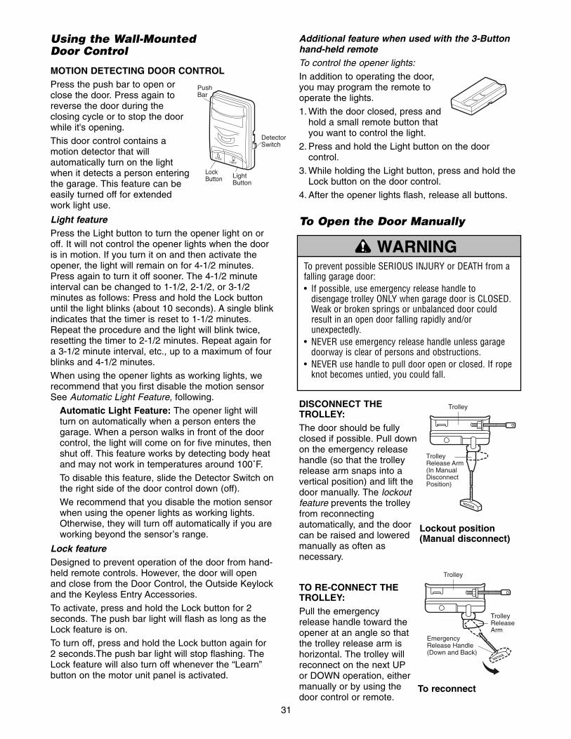
Additional feature when used with the 3-Buttonhand-held remoteTo control the opener lights:
In addition to operating the door,you may program the remote tooperate the lights.
1. With the door closed, press andhold a small remote button thatyou want to control the light.
2. Press and hold the Light button on the doorcontrol.
3. While holding the Light button, press and hold theLock button on the door control.
4. After the opener lights flash, release all buttons.
To Open the Door Manually
DISCONNECT THETROLLEY:The door should be fullyclosed if possible. Pull downon the emergency releasehandle (so that the trolleyrelease arm snaps into avertical position) and lift thedoor manually. The lockoutfeature prevents the trolleyfrom reconnectingautomatically, and the doorcan be raised and loweredmanually as often asnecessary.
TO RE-CONNECT THETROLLEY: Pull the emergencyrelease handle toward theopener at an angle so thatthe trolley release arm ishorizontal. The trolley willreconnect on the next UPor DOWN operation, eithermanually or by using thedoor control or remote.
To prevent possible SERIOUS INJURY or DEATH from afalling garage door:• If possible, use emergency release handle to
disengage trolley ONLY when garage door is CLOSED.Weak or broken springs or unbalanced door couldresult in an open door falling rapidly and/orunexpectedly.
• NEVER use emergency release handle unless garagedoorway is clear of persons and obstructions.
• NEVER use handle to pull door open or closed. If ropeknot becomes untied, you could fall.
WARNING
CAUTION WARNING
WARNING
Lockout position(Manual disconnect)
NOTICE
TrolleyRelease Arm (In ManualDisconnectPosition)
Trolley
To reconnect
NOTICE
EmergencyRelease Handle(Down and Back)
TrolleyReleaseArm
Trolley
Using the Wall-Mounted Door Control
MOTION DETECTING DOOR CONTROLPress the push bar to open orclose the door. Press again toreverse the door during theclosing cycle or to stop the doorwhile it's opening.
This door control contains amotion detector that willautomatically turn on the lightwhen it detects a person enteringthe garage. This feature can beeasily turned off for extended work light use.
Light featurePress the Light button to turn the opener light on oroff. It will not control the opener lights when the dooris in motion. If you turn it on and then activate theopener, the light will remain on for 4-1/2 minutes.Press again to turn it off sooner. The 4-1/2 minuteinterval can be changed to 1-1/2, 2-1/2, or 3-1/2minutes as follows: Press and hold the Lock buttonuntil the light blinks (about 10 seconds). A single blinkindicates that the timer is reset to 1-1/2 minutes.Repeat the procedure and the light will blink twice,resetting the timer to 2-1/2 minutes. Repeat again fora 3-1/2 minute interval, etc., up to a maximum of fourblinks and 4-1/2 minutes.
When using the opener lights as working lights, werecommend that you first disable the motion sensorSee Automatic Light Feature, following.
Automatic Light Feature: The opener light willturn on automatically when a person enters thegarage. When a person walks in front of the doorcontrol, the light will come on for five minutes, thenshut off. This feature works by detecting body heatand may not work in temperatures around 100˚F.
To disable this feature, slide the Detector Switch onthe right side of the door control down (off).
We recommend that you disable the motion sensorwhen using the opener lights as working lights.Otherwise, they will turn off automatically if you areworking beyond the sensor’s range.
Lock featureDesigned to prevent operation of the door from hand-held remote controls. However, the door will openand close from the Door Control, the Outside Keylockand the Keyless Entry Accessories.
To activate, press and hold the Lock button for 2seconds. The push bar light will flash as long as theLock feature is on.
To turn off, press and hold the Lock button again for2 seconds.The push bar light will stop flashing. TheLock feature will also turn off whenever the “Learn”button on the motor unit panel is activated.
LOCKLIGHT
PushBar
Lock Button Light
Button
Detector Switch

32
CARE OF YOUR OPENERLIMIT AND FORCE ADJUSTMENTS:Weather conditions maycause some minor changesin door operation requiringsome re-adjustments,particularly during the firstyear of operation.
Pages 27 and 28 refer to thelimit and force adjustments.Only a screwdriver isrequired. Follow theinstructions carefully.
Repeat the safety reverse test (AdjustmentStep 3, page 29) after any adjustment of limits orforce.
FORCE CONTROLS
1
3
9
7
5
1
3
9
7
5
LIMIT CONTROLS
KG KG
THE REMOTE CONTROL BATTERY
The lithium battery shouldproduce power for up to5 years. To replace battery,use the visor clip orscrewdriver blade to pry openthe case as shown. Insertbattery positive side up (+).
Dispose of old batteryproperly.
NOTICE: To comply with FCC and or Industry Canada rules (IC), adjustment ormodifications of this receiver and/or transmitter are prohibited, except for changing thecode setting or replacing the battery. THERE ARE NO OTHER USER SERVICEABLE PARTS.Tested to Comply with FCC Standards FOR HOME OR OFFICE USE. Operation is subject tothe following two conditions: (1) this device may not cause harmful interference, and(2) this device must accept any interference received, including interference that maycause undesired operation.
To prevent possible SERIOUS INJURY or DEATH:• NEVER allow small children near batteries.• If battery is swallowed, immediately notify doctor.
WARNING
CAUTION WARNING
WARNING
MAINTENANCE SCHEDULE
Once a Month• Manually operate door. If it is unbalanced or
binding, call a trained door systems technician.
• Check to be sure door opens & closes fully. Adjustlimits and/or force if necessary. (See pages 27and 28)
• Repeat the safety reverse test. Make anynecessary adjustments. (See Adjustment Step 3)
Twice a Year• Check chain tension. Disconnect trolley first. Adjust
if necessary. (See page 11)
Once a Year• Oil door rollers, bearings and hinges. The opener
does not require additional lubrication. Do notgrease the door tracks.
Battery positive side up (+)

33
HAVING A PROBLEM?
1. My door will not close and the light bulbs blinkon my motor unit: The safety reversing sensormust be connected and aligned correctly before thegarage door opener will move in the down direction.
• Verify the safety sensors are properly installed,aligned and free of any obstructions. Refer toInstallation Step 10: Install The ProtectorSystem®.
• Check diagnostic LED for flashes on the motorunit then refer to the Diagnostic Chart on thefollowing page.
2. My remotes will not activate the door:• Verify your Motion Detecting Door Control is not
blinking. If it is blinking, deactivate the Lock Modefollowing the instructions for Using theMotion Detecting Door Control.
• Reprogram remotes following the programminginstructions. Refer to Programming.
• If remote will still not activate your door, checkdiagnostic LED for flashes on motor unit thenrefer to Diagnostic Chart on the following page.
3. My door reverses for no apparent reason:Repeat safety reverse test after adjustments toforce or travel limits. The need for occasionaladjustment for the force and limit settings is normal.Weather conditions in particular can affect doortravel.
• Manually check door for balance or any bindingproblems.
• Refer to Adjustment Step 2, Adjust the Force.
4. My door reverses for no apparent reason afterfully closing and touching the floor: Repeatsafety reverse test after adjustments to force ortravel limits. The need for occasional adjustment forthe force and limit settings is normal. Weatherconditions in particular can affect door travel.
• Refer to Adjustment Step 1, Adjust the UP andDOWN Travel Limits. Decrease down travel byturning down limit adjustment screw clockwise.
5. My lights will not turn off when door is open:• The garage door opener is equipped with a
security light feature. This feature activates thelight on when the safety sensor beam has beenobstructed. Refer to Operation section; Using theWall Mounted Door Control, Light Feature.
Receiving Eye Safety ReversingSensor (Green Indicator Light)
Sending Eye Safety ReversingSensor (Amber Indicator Light)
6. My motor unit hums briefly:• First verify that the trolley is against the stop bolt.
• Release the door from the opener by pulling theEmergency Release Rope.
• Manually bring the door to a closed position.
• Loosen the chain by adjusting the outer nut 4 to5 turns. This relieves the tension.
• Run the motor unit from the remote control ordoor control. The trolley should travel towardsthe door and stop. If the trolley re-engages withthe door, pull the Emergency Release Rope todisengage.
• Decrease the UP travel by turning the UP Traveladjustment screw 2 full turns away from the arrow.
• Re-tighten the outer nut so the chain is a 1/4" (6 mm) above the base of the rail. (Whenthe door is reconnected and closed, the chainwill sag. This is normal.)
• If the trolley does not move away from the bolt,repeat the steps above.
Safety Reversing Sensor
Bell Wire
"Learn" Button LED or Diagnostic LED
KG
1
3
9
7
5
KG
1
3
9
7
5

34
Installed Safety Reversing
Sensor
Safety Reversing Sensor
Bell Wire
LED or Diagnostic LED
"Learn" Button
KG
1
3
9
7
5
KG
1
3
9
7
5
DiagnosticsLocated On Motor Unit
Your garage door opener is programmed with self-diagnostic capabilities. The “Learn” button/diagnosticLED will flash a number of times then pause signifying ithas found a potential issue. Consult Diagnostic Chart below.
Diagnostic Chart
Symptom: One or both of the Indicator lights on the safety sensors do not glow steady.• Inspect sensor wires for a short (staple in wire), correct wiring polarity
(black/white wires reversed), broken or disconnected wires, replace/attach as needed.
• Disconnect all wires from back of motor unit.• Remove sensors from brackets and shorten sensor wires to 1-2 ft (30-60 cm)
from back each of sensor.• Reattach sending eye to motor unit using shortened wires. If sending eye
indicator light glows steadily, attach the receiving eye. • Align sensors, if the indicator lights glow replace the wires for the sensors. If
the sensor indicator lights do not light, replace the safety sensors.
Symptom: LED is not lit on door control.• Inspect door control/wires for a short (staple in wire), replace as needed.• Disconnect wires at door control, touch wires together. If motor unit activates,
replace door control.• If motor unit does not activate, disconnect door control wires from motor unit.
Momentarily short across red and white terminals with jumper wire. If motorunit activates, replace door control wires.
Symptom: Sending indicator light glows steadily, receiving indicator lightis dim or flashing.• Realign receiving eye sensor, clean lens and secure brackets. • Verify door track is firmly secured to wall and does not move.
Symptom: Motor has overheated; the motor unit does not operate ortrolley is stuck on stop bolt = Motor unit hums briefly; RPM Sensor = Short travel 6-8" (15-20 cm). • Unplug unit to reset. Try to operate motor unit, check diagnostic code.• If it is still flashing 5 times and motor unit moves 6-8" (15-20 cm), replace RPM
sensor. • If motor unit doesn’t operate, motor unit is overheated. Wait 30 minutes and
retry. If motor unit still will not operate replace logic board.
Symptom: Motor unit doesn’t operate.• Replace logic board because motor rarely fails.Motor Circuit Failure.
Replace Receiver Logic Board.
Motor overheated orpossible RPM sensorfailure. Unplug to reset.
Safety reversing sensors slightly misaligned (dim or flashing LED).
Door control or wire shorted.
Safety reversing sensorswire shorted orblack/white wirereversed.
Safety reversing sensorswire open (broken ordisconnected).
1 FLASH
2 FLASHES
3 FLASHES
4 FLASHES
5 FLASHES
6 FLASHES
OR

*3-Button RemotesIf provided with your garage door opener, the largebutton is factory programmed to operate it. Additionalbuttons on anySecurity✚® 3-Buttonremote or compactremote can beprogrammed to operateother Security✚®
garage door openers.
To Erase All Codes From MotorUnit Memory
To deactivate any unwanted remote,first erase all codes:Press and hold the “learn” button onmotor unit until the learn indicator lightgoes out (approximately 6 seconds). Allprevious codes are now erased. Reprogram eachremote or keyless entry you wish to use.
KG
1
3
9
7
5
KG
1
3
9
7
5
1. Press and release the “learn”button on the motor unit. Thelearn indicator light will glowsteadily for 30 seconds.
2. Within 30 seconds, press andhold the button on the hand-heldremote* that you wish to operateyour garage door.
3. Release the button when themotor unit lights blink. It haslearned the code. If light bulbs arenot installed, two clicks will beheard.
PROGRAMMING
35
Your garage door opener has already been programmed at the factory to operate with your hand-held remotecontrol. The door will open and close when you press the large push button.
Below are instructions for programming your opener to operate with additional Security✚® remote controls.
NOTICE: If this Security✚® garage door opener is operated with a non-rolling code transmitter, the technicalmeasure in the receiver of the garage door opener, which provides security against code-theft devices, will becircumvented. The owner of the copyright in the garage door opener does not authorize the purchaser orsupplier of the non-rolling code transmitter to circumvent that technical measure.
To Add or Reprogram a Hand-held Remote Control
USING THE “LEARN” BUTTON USING THE MOTION DETECTING DOOR CONTROL
LOCKLIGHT
1. Press and hold the button on thehand-held remote* that you wishto operate your garage door.
2. While holding the remote button,press and hold the LIGHT buttonon the Motion Detecting DoorControl.
3. Continue holding both buttonswhile you press the push bar onthe Motion Detecting Door Control(all three buttons are held).
4. Release buttons when the motorunit lights blink. It has learned thecode. If light bulbs are notinstalled, two clicks will be heard.
LOCKLIGHT
LOCKLIGHT
LOCKLIGHT
KG
1
3
9
7
5
KG
1
3
9
7
5

1. Press and release the “learn”button on motor unit. The learnindicator light will glow steadily for30 seconds.
2. Within 30 seconds, enter a fourdigit personal identificationnumber (PIN) of your choice onthe keypad. Then press and holdthe ENTER button.
3. Release the button when themotor unit lights blink. It haslearned the code. If light bulbs arenot installed, two clicks will beheard.
To change an existing, known PINIf the existing PIN is known, it may be changed by oneperson without using a ladder.1. Press the four buttons for the present PIN, then
press and hold the # button.The opener light will blink twice. Release the #button.
2. Press the new 4-digit PIN you have chosen, thenpress Enter.
The motor unit lights will blink once when the PIN hasbeen learned.Test by pressing the new PIN, then press Enter. Thedoor should move.
To set a temporary PINYou may authorize access by visitors or service peoplewith a temporary 4-digit PIN. After a programmednumber of hours or number of accesses, this temporaryPIN expires and will no longer open the door. It can beused to close the door even after it has expired. To seta temporary PIN:1. Press the four buttons for your personal entry PIN
(not the last temporary PIN), then press and hold the✽ button.The opener light will blink three times. Release thebutton.
2. Press the temporary 4-digit PIN you have chosen,then press Enter.The opener light will blink four times.
3. To set the number of hours this temporary PIN willwork, press the number of hours (up to 255), thenpress ✽.
OR3. To set the number of times this temporary PIN will
work, press the number of times (up to 255), thenpress #.
The opener light will blink once when the temporary PINhas been learned.Test by pressing the four buttons for the temporary PIN,then press Enter. The door should move. If thetemporary PIN was set to a certain number of openings,remember that the test has used up one opening. Toclear the temporary password, repeat steps 1-3, settingthe number of hours or times to 0 in step 3.
36
KG
1
3
9
7
5
KG
1
3
9
7
5
LOCKLIGHT
1. Enter a four digit personalidentification number (PIN) of yourchoice on the keypad. Then pressand hold ENTER.
2. While holding the ENTER button,press and hold the LIGHT buttonon the Motion Detecting DoorControl.
3. Continue holding the ENTER andLIGHT buttons while you pressthe push bar on the MotionDetecting Control (all threebuttons are held).
4. Release buttons when the motorunit lights blink. It has learned thecode. If light bulbs are notinstalled, two clicks will be heard.
To Add, Reprogram or Change a Keyless Entry PINNOTE: Your new Keyless Entry must be programmed to operate your garage door opener.
USING THE “LEARN” BUTTON USING THE MOTION DETECTING DOOR CONTROL
NOTE: This method requires two people if the KeylessEntry is already mounted outside the garage.
LOCKLIGHT
LOCKLIGHT
LOCKLIGHT
One Button Close: Opener can be closed by pressing only the ENTER button if the one button close featurehas been activated. This feature has been activated at the factory. To activate or deactivate this feature pressand hold buttons 1 and 9 for 10 seconds. The keypad will blink twice when the one button close is active. Thekeypad will blink four times when one button close is deactivated.
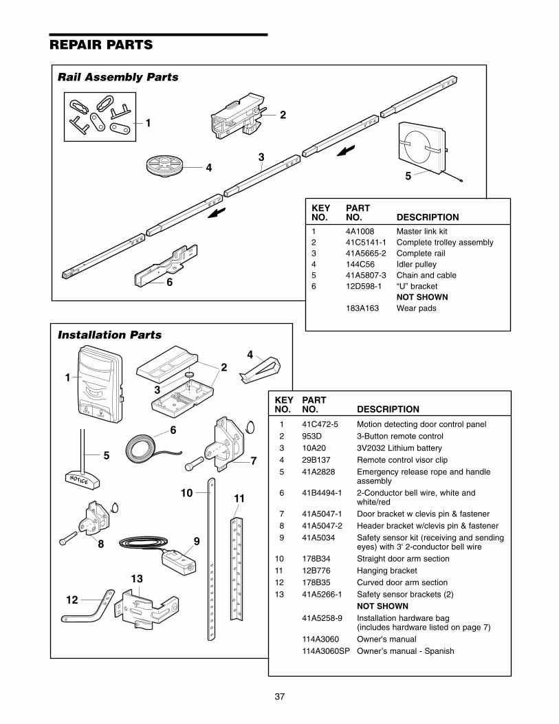
3
1
54
2
6
37
REPAIR PARTS
Rail Assembly Parts
KEY PARTNO. NO. DESCRIPTION
1 4A1008 Master link kit2 41C5141-1 Complete trolley assembly3 41A5665-2 Complete rail4 144C56 Idler pulley5 41A5807-3 Chain and cable6 12D598-1 “U” bracket
NOT SHOWN183A163 Wear pads
7
10
12
5
NOTICE
6
4
3
2
9
13
8
1
11
LOCKLIGHT
Installation Parts
KEY PARTNO. NO. DESCRIPTION
1 41C472-5 Motion detecting door control panel2 953D 3-Button remote control 3 10A20 3V2032 Lithium battery4 29B137 Remote control visor clip5 41A2828 Emergency release rope and handle
assembly6 41B4494-1 2-Conductor bell wire, white and
white/red7 41A5047-1 Door bracket w clevis pin & fastener8 41A5047-2 Header bracket w/clevis pin & fastener9 41A5034 Safety sensor kit (receiving and sending
eyes) with 3' 2-conductor bell wire10 178B34 Straight door arm section11 12B776 Hanging bracket12 178B35 Curved door arm section13 41A5266-1 Safety sensor brackets (2)
NOT SHOWN41A5258-9 Installation hardware bag
(includes hardware listed on page 7)114A3060 Owner's manual114A3060SP Owner’s manual - Spanish

Motor Unit Assembly Parts
38
DN
UP
BrownWire
(Down)Contact
LIMIT SWITCHASSEMBLY
GreyWire
YellowWire
(Up)Contact
Center LimitContact
DriveGear
24
3
1
14
18 8A
16
517
9
10
15
1312
66
11
8B
8C
77
KEY PARTNO. NO. DESCRIPTION
1 41A5615 Chain Spreader2 41A5585 Gear and sprocket assembly.
Complete with: Spring washer,thrust washer, retaining ring,bearing plate, roll pins (2), drivegear and worm gear, helical gearw/retainer and grease
3 41A2817 Drive/worm gear kit w/grease, roll pins (2)
4 41B4245 Line cord5 41A5484-1 End panels w/all labels 6 4A1344 Light socket7 108D79 Lens 8A 30B530 Capacitor 56uF8B 30B529 Capacitor 40uF8C 41A5637 Resistor9 41A3150 Terminal block w/screws
10 41D5563 Universal replacement motor &bracket assembly. Completewith: Motor, worm, bracket,bearing assembly, RPM sensor
KEY PARTNO. NO. DESCRIPTION
11 41A5633-2 Cover 12 41A2818 Limit switch drive & retainer13 41D3452-2 Limit switch assembly14 41A2822-1 Interrupter cup15 41C4398A RPM sensor assembly16 41AC075-2 Receiver logic board assembly.
Complete with: Logic board, endpanel w/all labels, light socket
17 41C5588 High voltage wire harness41C5587 Low voltage wire harness
18 41D180-1 End panel w/all labels
NOT SHOWN41A2826 Motor shaft bearing kit41A2825 Opener assembly hardware kit
(includes screws not designatedby a number in illustration)

39
ACCESSORIES
LOCKLIGHT
CLOSED
OPEN
LOCKLIGHT
3-Button SECURITY✚® RemoteControl:Includes visor clip.
SECURITY✚® Keyless Entry:Enables homeowner to operate garagedoor opener from outside by entering apassword on a specially designedkeyboard. Also can add a temporarypassword for visitors or servicepersons. This temporary password canbe limited to a programmable numberof hours or entries.
41A5281935CB
7702CB953D Outside Quick Release:Required for a garage with NOaccess door.
Extension Brackets:(Optional) For safety sensorinstallation onto the wall or floor.To order call: 1-800-528-9131
Motion Detecting Control Panel:Multi-Function door control withmotion sensor that automaticallyturns opener lights on for 5minutes when it detects a personentering the garage. Sensor canbe easily deactivated whendesired.
3-Button Mini-Remote Controlwith SECURITY✚®:With key ring and fasteningstrip.
956D
940D
10 Foot (3.06 m) Rail Extension:To allow a 10 foot (3.06 m) door toopen fully.
Multi-Function DoorControl Panel:Provides a Lock feature whichprevents operation of garage dooropener from portable remotes anda Light feature for constant light.
945CB
CLDM1 Garage Door Monitor:Monitors the status of your garagedoor from inside your home.
CLLAT Remote Light Control:Enables homeowner to turn on alamp, television or other appliancefrom their car with their garage dooropener remote or from anywhere intheir home with an additionalChamberlain Security✚® remote.
7710CB
8 Foot (2.44 m) Rail Extension:To allow an 8 foot (2.44 m) doorto open fully.
7708CB
760CB Outdoor Key Switch:Operates the garage doorautomatically from outside whenremote control is not handy.

© 2006, The Chamberlain Group, Inc.114A3060E All Rights Reserved
CHAMBERLAIN® SERVICEIS ON CALL
OUR LARGE SERVICE ORGANIZATIONSPANS AMERICA
INSTALLATION AND SERVICE INFORMATION IS ASNEAR AS YOUR TELEPHONE. SIMPLY DIAL OUR
TOLL FREE NUMBER:
1-800-528-9131
www.chamberlain-diy.com
For professional installation, parts and service,contact your local CHAMBERLAIN® dealer. Look for himin the Yellow Pages, or call our Service number for alist of dealers in your area.
HOW TO ORDERREPAIR PARTS
Selling prices will be furnished on request, or parts willbe shipped at prevailing prices and you will be billedaccordingly.
WHEN ORDERING REPAIR PARTS, ALWAYS GIVETHE FOLLOWING INFORMATION:
• PART NUMBER
• PART NAME
• MODEL NUMBER
ADDRESS ORDERS TO:
THE CHAMBERLAIN GROUP, INC.Technical Support Group
6020 S. Country Club RoadTucson, Arizona 85706
SERVICE INFORMATIONTOLL FREE NUMBER:
1-800-528-9131
LIFTMASTER® ONE YEAR LIMITED WARRANTYLIFETIME MOTOR LIMITED WARRANTY
The Chamberlain Group, Inc. (“Seller”) warrants to the first retail purchaser of this product, for the residence in which thisproduct is originally installed, that it is free from defect in materials and/or workmanship for a period of one year from the dateof purchase [and that the motor is free from defect in materials and/or workmanship for the lifetime of the product]. The properoperation of this product is dependent on your compliance with the instructions regarding installation, operation, maintenanceand testing. Failure to comply strictly with those instructions will void this limited warranty in its entirety.
If, during the limited warranty period, this product appears to contain a defect covered by this limited warranty, call 1-800-528-9131, toll free, before dismantling this product. Then send this product, pre-paid and insured, to our service center for warrantyrepair. You will be advised of shipping instructions when you call. Please include a brief description of the problem and a datedproof-of-purchase receipt with any product returned for warranty repair. Products returned to Seller for warranty repair, whichupon receipt by Seller are confirmed to be defective and covered by this limited warranty, will be repaired or replaced (at Seller’ssole option) at no cost to you and returned pre-paid. Defective parts will be repaired or replaced with new or factory-rebuilt partsat Seller’s sole option.
ALL IMPLIED WARRANTIES FOR THE PRODUCT, INCLUDING BUT NOT LIMITED TO ANY IMPLIED WARRANTIES OFMERCHANTABILITY AND FITNESS FOR A PARTICULAR PURPOSE, ARE LIMITED IN DURATION TO THE ONE YEARLIMITED WARRANTY PERIOD SET FORTH ABOVE [EXCEPT THE IMPLIED WARRANTIES WITH RESPECT TO THEMOTOR, WHICH ARE LIMITED IN DURATION TO THE LIFETIME LIMITED WARRANTY PERIOD FOR THE MOTOR], ANDNO IMPLIED WARRANTIES WILL EXIST OR APPLY AFTER SUCH PERIOD. Some States do not allow limitations on howlong an implied warranty lasts, so the above limitation may not apply to you. THIS LIMITED WARRANTY DOES NOTCOVER NON-DEFECT DAMAGE, DAMAGE CAUSED BY IMPROPER INSTALLATION, OPERATION OR CARE(INCLUDING, BUT NOT LIMITED TO ABUSE, MISUSE, FAILURE TO PROVIDE REASONABLE AND NECESSARYMAINTENANCE, UNAUTHORIZED REPAIRS OR ANY ALTERATIONS TO THIS PRODUCT), LABOR CHARGES FORREINSTALLING A REPAIRED OR REPLACED UNIT, REPLACEMENT OF BATTERIES AND LIGHT BULBS OR UNITSINSTALLED FOR NON-RESIDENTIAL USE.THIS LIMITED WARRANTY DOES NOT COVER ANY PROBLEMS WITH, OR RELATING TO, THE GARAGE DOOR ORGARAGE DOOR HARDWARE, INCLUDING BUT NOT LIMITED TO THE DOOR SPRINGS, DOOR ROLLERS, DOORALIGNMENT OR HINGES. THIS LIMITED WARRANTY ALSO DOES NOT COVER ANY PROBLEMS CAUSED BYINTERFERENCE. ANY SERVICE CALL THAT DETERMINES THE PROBLEM HAS BEEN CAUSED BY ANY OF THESEITEMS COULD RESULT IN A FEE TO YOU.UNDER NO CIRCUMSTANCES SHALL SELLER BE LIABLE FOR CONSEQUENTIAL, INCIDENTAL OR SPECIALDAMAGES ARISING IN CONNECTION WITH USE, OR INABILITY TO USE, THIS PRODUCT. IN NO EVENT SHALLSELLER’S LIABILITY FOR BREACH OF WARRANTY, BREACH OF CONTRACT, NEGLIGENCE OR STRICT LIABILITYEXCEED THE COST OF THE PRODUCT COVERED HEREBY. NO PERSON IS AUTHORIZED TO ASSUME FOR US ANYOTHER LIABILITY IN CONNECTION WITH THE SALE OF THIS PRODUCT.Some States do not allow the exclusion or limitation of consequential, incidental or special damages, so the above limitation orexclusion may not apply to you. This limited warranty gives you specific legal rights, and you may also have other rights whichvary from state to state.