Embed Size (px)
Citation preview

F14-503 June, 2003
Installation, Operation, and Maintenance Manual for the
Piecemaker 2 GANTRY SHAPE CUTTING MACHINE
411 S. Ebenezer Road Florence, SC 29501-0545

The equipment described in this manual is potentially hazardous. Use caution when installing, operating and maintaining this equipment.
The purchaser is solely responsible for the safe operation and use of all products purchased, including compliance with OSHA and other government standards. ESAB Cutting Systems has no liability for personal injury or other damage arising out of the use of any product manufactured or sold by ESAB. See standard ESAB terms and conditions of sale for a specific statement of ESAB’s responsibilities and limitations on its liability.
ESAB Cutting Systems is not responsible for any errors that may appear in this document. Information in this document is subject to change without notice.
This manual is ESAB Part No. F14-503.
This manual is for the convenience and use of the cutting machine purchaser. It is not a contract or other obligation on the part of ESAB Cutting Systems.
ESAB Cutting Systems, 2003
Printed In U.S.A.

This manual is not a safety guide for use of the equipment. The purchaser, through its own judgment and safety procedures, is solely responsible for safe operation. However, in presenting the information in this manual, a system of advisory notes has been provided to point out specific information that will be helpful in safe and proper operation of the equipment.
The following definitions apply to DANGER, WARNING, and CAUTION found throughout this manual:
Used to call attention to immediate hazards which, if not avoided, will result in immediate, serious personal injury or loss of life.
Used to call attention to potential hazards that could result in personal injury or loss of life.
Used to call attention to hazards that could result in minor personal injury.
Used to call attention to potential hazards which, if not avoided, could result in property damage.
The following definition applies to NOTICE found throughout this manual:
Used to call attention to important installation, operation, or maintenance information not directly related to safety hazards.

Contents
Section 1 Safety
Section 2 General Information
Section 3 Installation
Section 4 Operation
Section 5 Maintenance
Section 6 Replacement Parts
Contents

Piecemaker 2

Preface
The Piecemaker 2 is an advanced heavy duty
numerically controlled gantry cutting machine manufactured by ESAB Cutting Systems of Florence, South Carolina. The PieceMaker II may be equipped with various types of plasma cutting equipment. It is designed to provide years of dependable, accurate, repeatable part cutting, with a high degree of reliability, ease of service and ease of operation. There are optional features and configurations available for the Piecemaker 2. For completeness, all of these are described in this manual. However, not all options described in this manual are present on all machines. In addition, more capabilities and features may be added in the future, which are not covered in this manual. ESAB Cutting Systems reserves the right to change or add features and capabilities without notice. Before operating the machine, one should become familiar with this manual in its entirety, with special attention to the SAFETY section.
Contents
1.1 Introduction................................................................................. 1-1
1.2 General Safety Information......................................................... 1-2
1.3 Installation Precautions............................................................... 1-4
1.4 Electrical Grounding ................................................................... 1-5
1.5 Operating A Cutting Machine...................................................... 1-6
1.6 Working with Plasma Cutting Equipment.................................... 1-9
1.7 Service Precautions.................................................................. 1-15
1.8 Welding..................................................................................... 1-16
1.9 Working with Waterjet Cutting Equipment ................................ 1-17
1.10 Recommended References...................................................... 1-19
Safety
Contents

Piecemaker 2

Safety
Introduction Page 1-1

1.1 Introduction
The process of cutting metals with oxy-fuel or plasma equipment provides industry with a valuable and versatile tool. ESAB cutting machines are designed to provide both operation safety and efficiency. However, as with any machine tool, sensible attention to operating procedures, precautions, and safe practices is necessary to achieve a full measure of usefulness. Whether an individual is involved with operation, servicing, or as an observer, compliance with established precautions and safe practices must be accomplished. Failure to observe certain precautions could result in serious personnel injury or severe equipment damage. The following precautions are general guidelines applicable when working with cutting machines. More explicit precautions pertaining to the basic machine and accessories are found in the instruction literature. For a wide scope of safety information on the field of cutting and welding apparatus, obtain and read the publications listed in the Recommended References.
Piecemaker 2
Page 1-2 Introduction

1.2 General Safety Information
Machine starts automatically.
This equipment moves in various directions and speeds.
Moving machinery can crush.
1. Only qualified personnel should operate or service equipment.
2. Keep all personnel, materials, and equipment not involved in production process clear of entire system area.
3. Keep gear racks and rails clear of debris or obstructions, such as tools or clothing.
4. Fence off entire work cell to prevent personnel from passing through area or standing in the working envelope of the equipment.
5. Post appropriate WARNING signs at every work cell entrance.
6. Follow lockout procedure before servicing.
Safety
General Safety Information Page 1-3

Read and understand this operator’s manual before using machine.
Failure to follow operating instructions could result in death or serious injury.
1. Read entire procedure before operating or performing any system maintenance.
2. Special attention must be given to all hazard warnings that provide essential information regarding personnel safety and/or possible equipment damage.
3. All safety precautions relevant to electrical equipment and process operations must be strictly observed by all having system responsibility or access.
4. Read all safety publications made available by your company.
Read and understand all safety warning labels on machine.
Failure to follow safety warning label instructions could result in death or serious injury.
Refer to operator’s manual for additional safety information.
Piecemaker 2
Page 1-4 General Safety Information
1.3 Installation Precautions
Improperly installed equipment can cause injury or death.
Follow these guidelines while installing machine:
Flashback arrestors must be installed between service supply lines and machine as outlined in NFPA51B. Burn back to source can cause serious explosion or fire.
Properly identify all oxygen and fuel gas service lines and equip with correct fittings to prevent possibility of crossover connection.
Do not connect a cylinder directly to machine inlet. An appropriate cylinder regulator must be installed on a fuel gas cylinder to reduce pressure to a reasonable inlet supply pressure (20 PSIG maximum). Machine regulator is then used to obtain pressure required by torches.
Contact your ESAB representative before installation. He can suggest certain precautions regarding piping installation and machine lifting, etc. to ensure maximum security.
Never attempt any machine modifications or apparatus additions without first consulting a qualified ESAB representative.
Observe machine clearance requirements for proper operation and personnel safety.
Safety
Installation Precautions Page 1-5

1.4 Electrical Grounding
Electrical grounding is imperative for proper machine operation and SAFETY. Refer to this manual’s Installation section for detailed grounding instructions.
Electric shock hazard.
Improper grounding can cause severe injury or death.
Machine must be properly grounded before put into service.
Improper grounding can damage machine and electrical components.
1. Machine must be properly grounded before put into service.
2. Cutting table must be properly grounded to a good Earth ground rod.
Piecemaker 2
Page 1-6 Electrical Grounding

1.5 Operating A Cutting Machine
Crush hazard.
Moving machine can crush.
Machine moves automatically.
1. Stay clear of rails and cutting table during operation.
2. Follow lockout procedure before servicing.
Flying debris and loud noise hazards.
Hot spatter can burn and injure eyes.
Loud noise can injure ears.
1. Wear goggles to protect eyes from burns and flying debris generated during operation.
2. Wear ear protection as required for cutting various materials.
Burn hazard.
Hot metal can burn.
1. Do not touch metal plate or parts immediately after cutting. Allow metal time to cool, or douse with water.
2. Do not touch plasma torch immediately after cutting. Allow torch time to cool.
Safety
Operating A Cutting Machine Page 1-7

Crush hazard.
Moving parts can cut and crush.
1. Keep hands clear of drive gears.
2. Do not operate with any protective covers removed.
3. Follow lockout procedure before servicing.
Hazardous voltages.
Electric shock can kill.
1. Do not operate with any protective covers removed or electrical component boxes open.
2. Follow lockout procedures before servicing.
Piecemaker 2
Page 1-8 Operating A Cutting Machine

Pinch hazard.
Moving vertical slides can crush or pinch.
Keep hands clear of torch and slide during operation.
Pinch hazard.
Moving carriages can crush or pinch.
Keep hands clear of carriages during operation.
Safety
Operating A Cutting Machine Page 1-9

1.6 Working with Plasma Cutting Equipment
Hazardous voltages.
Electric shock can kill.
1. Do NOT touch plasma torch, cutting table or cable connections during plasma cutting process.
2. Always turn power off to plasma power supplies before touching or servicing plasma torch.
3. Always turn power off to plasma power supplies before opening or servicing plasma plumbing or flow control box.
4. Do not touch live electrical parts.
5. Keep all panels and covers in place when machine is connected to power source.
6. Insulate yourself from workpiece and electrical ground: wear insulating gloves, shoes and clothing.
7. Keep gloves, shoes, clothing, work area, and equipment dry.
Piecemaker 2
Page 1-10 Working with Plasma Cutting Equipment
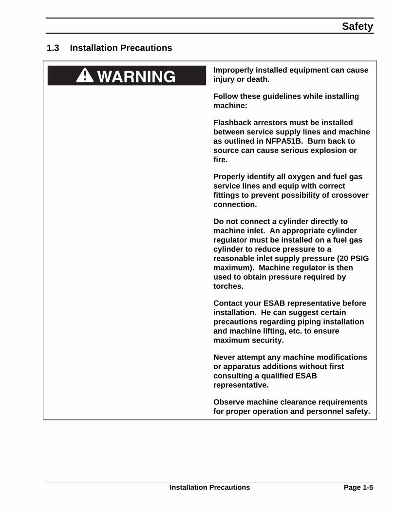
Toxic fume hazard.
The cutting process can produce poisonous fumes and toxic gases.
Certain chlorinated solvents decompose and form phosgene gas when exposed to ultraviolet radiation.
Do not cut metal or painted metals containing zinc, lead, cadmium or beryllium unless fume removal equipment is installed and operating properly.
1. Keep cutting area well ventilated.
2. Wear proper breathing mask when cutting galvanized metal and use proper ventilation and fume removal methods.
3. Insure chlorinated solvents are not in cutting area.
Safety
Working with Plasma Cutting Equipment Page 1-11

Radiation hazard.
Arc rays can injure eyes and burn skin.
1. Wear correct eye and body protection.
2. Wear dark safety glasses or goggles with side shields. Refer to following chart for recommended lens shades for plasma cutting:
Arc Current Lens Shade
Up to 100 Amps Shade No. 8 100-200 Amps Shade No. 10 200-400 Amps Shade No. 12 Over 400 Amps Shade No. 14
3. Replace glasses/goggles when lenses are pitted or broken
4. Warn others in area not to look directly at the arc unless wearing appropriate safety glasses.
5. Prepare cutting area to reduce reflection and transmission of ultraviolet light.
6. Paint walls and other surfaces with dark colors to reduce reflections.
7. Install protective screens or curtains to reduce ultraviolet transmission.
Noise hazard.
Noise from plasma arc can damage hearing.
Wear correct ear protection when cutting above water.
Piecemaker 2
Page 1-12 Working with Plasma Cutting Equipment
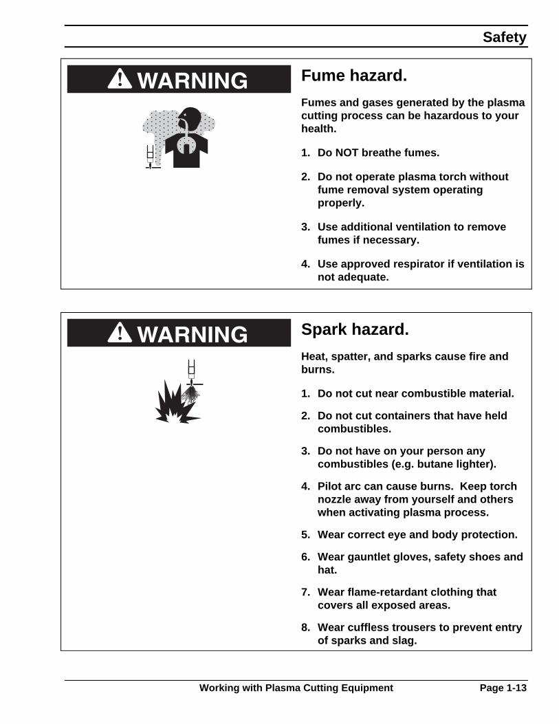
Fume hazard.
Fumes and gases generated by the plasma cutting process can be hazardous to your health.
1. Do NOT breathe fumes.
2. Do not operate plasma torch without fume removal system operating properly.
3. Use additional ventilation to remove fumes if necessary.
4. Use approved respirator if ventilation is not adequate.
Spark hazard.
Heat, spatter, and sparks cause fire and burns.
1. Do not cut near combustible material.
2. Do not cut containers that have held combustibles.
3. Do not have on your person any combustibles (e.g. butane lighter).
4. Pilot arc can cause burns. Keep torch nozzle away from yourself and others when activating plasma process.
5. Wear correct eye and body protection.
6. Wear gauntlet gloves, safety shoes and hat.
7. Wear flame-retardant clothing that covers all exposed areas.
8. Wear cuffless trousers to prevent entry of sparks and slag.
Safety
Working with Plasma Cutting Equipment Page 1-13

Hydrogen explosion hazard.
Hydrogen explosions can cause personal injury or death.
Hydrogen can create explosive gas pockets in the water table. These pockets will explode when ignited by sparks or the plasma arc.
1. Before cutting, be aware of possible hydrogen sources in the water table – molten metal reaction, slow chemical reaction and some plasma gases.
2. Explosive gas pockets accumulate underneath the cutting plate and inside the water table.
3. Clean slag (especially fine particles) from bottom of table frequently. Refill table with clean water.
4. Do not leave plate on table overnight.
5. If water table has not been used for several hours, vibrate or jolt it to break up hydrogen pockets before laying plate on the table.
6. If possible, change water level between cuts to break up hydrogen pockets.
7. Maintain water pH level near 7 (neutral).
8. Programmed part spacing should be a minimum of twice the kerf width to ensure material is always under the kerf.
9. If cutting underwater, aerate water under plate with compressed air to prevent hydrogen pockets.
10. If cutting above water, use fans to circulate air between plate and water surface.
Piecemaker 2
Page 1-14 Working with Plasma Cutting Equipment

Explosion hazard.
Certain molten aluminum-lithium (Al-Li) alloys can cause explosions when plasma cut with water.
Do not plasma cut the following Al-Li alloys with water:
Alithlite (Alcoa) X8192 (Alcoa) Alithally (Alcoa) Navalite (US Navy) 2090 Alloy (Alcoa) Lockalite (Lockheed) X8090A (Alcoa) Kalite (Kaiser) X8092 (Alcoa) 8091 (Alcan)
These alloys should only be dry cut on a dry table.
DO NOT dry cut over water.
DO NOT water injection cut.
Contact your aluminum supplier for additional safety information regarding hazards associated with these alloys.
Safety
Working with Plasma Cutting Equipment Page 1-15
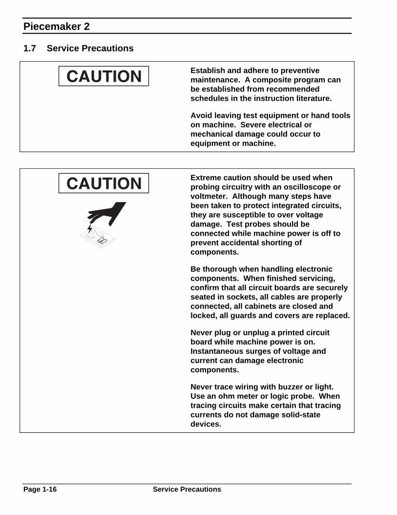
1.7 Service Precautions
Establish and adhere to preventive maintenance. A composite program can be established from recommended schedules in the instruction literature.
Avoid leaving test equipment or hand tools on machine. Severe electrical or mechanical damage could occur to equipment or machine.
Extreme caution should be used when probing circuitry with an oscilloscope or voltmeter. Although many steps have been taken to protect integrated circuits, they are susceptible to over voltage damage. Test probes should be connected while machine power is off to prevent accidental shorting of components.
Be thorough when handling electronic components. When finished servicing, confirm that all circuit boards are securely seated in sockets, all cables are properly connected, all cabinets are closed and locked, all guards and covers are replaced.
Never plug or unplug a printed circuit board while machine power is on. Instantaneous surges of voltage and current can damage electronic components.
Never trace wiring with buzzer or light. Use an ohm meter or logic probe. When tracing circuits make certain that tracing currents do not damage solid-state devices.
Piecemaker 2
Page 1-16 Service Precautions

1.8 Welding
Special precautions must be observed if any arc welding is performed on this machine.
Failure to observe the following precautions can result in large induced currents causing severe damage to electronic components in machine control system.
Machine damage caused by improper welding practices is considered abuse and voids certain warranty provisions.
1. Disconnect all cables to Relay Box, Numerical Controller, Tracer System, and Control Console.
2. Always connect welder ground cable directly to the part to be welded and as close to the weld point as possible.
3. Keep the current path between the ground point and the weld as short as possible.
4. Never connect the ground to points where the welding current path could include moving parts or bolted joints. This can result in a high resistance circuit that could divert high current into the control system and damage mechanical components (e.g. bearings).
Safety
Welding Page 1-17
1.9 Working with Waterjet Cutting Equipment
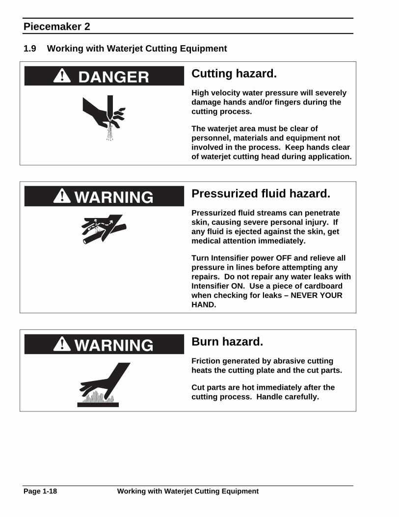
Cutting hazard.
High velocity water pressure will severely damage hands and/or fingers during the cutting process.
The waterjet area must be clear of personnel, materials and equipment not involved in the process. Keep hands clear of waterjet cutting head during application.
Pressurized fluid hazard.
Pressurized fluid streams can penetrate skin, causing severe personal injury. If any fluid is ejected against the skin, get medical attention immediately.
Turn Intensifier power OFF and relieve all pressure in lines before attempting any repairs. Do not repair any water leaks with Intensifier ON. Use a piece of cardboard when checking for leaks – NEVER YOUR HAND.
Burn hazard.
Friction generated by abrasive cutting heats the cutting plate and the cut parts.
Cut parts are hot immediately after the cutting process. Handle carefully.
Piecemaker 2
Page 1-18 Working with Waterjet Cutting Equipment
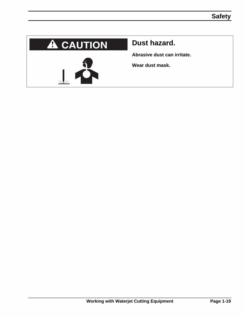
Dust hazard.
Abrasive dust can irritate.
Wear dust mask.
Safety
Working with Waterjet Cutting Equipment Page 1-19
1.10 Recommended References
The following nationally recognized publications on safety in welding and cutting operations are recommended. These publications have been prepared to protect persons from injury or illness and to protect property from damage, which could result from unsafe practices. Although some of these publications are not related specifically to this type of industrial cutting apparatus, the principles of safety apply equally.
“Precautions and Safe Practices in welding and Cutting with Oxygen-Fuel Gas Equipment,” Form 2035. ESAB Cutting Systems.
“Precautions and Safe Practices for Electric Welding and Cutting,” Form 52-529. ESAB Cutting Systems.
“Safety in Welding and Cutting” - ANSI Z 49.1, American Welding Society, 2501 NW 7th Street, Miami, Florida, 33125.
“Recommended Practices for Shielded Gases for Welding and Plasma Arc Cutting” – AWS C5.10-94, American Welding Society.
“Standard for Fire Protection in Use of Cutting and Welding Procedures” - NFPA 51B, National Fire Protection Association, 60 Batterymarch Street, Boston, Massachusetts, 02110.
“Standard for Installation and Operation of Oxygen - Fuel Gas Systems for Welding and Cutting” - NFPA 51, National Fire Protection Association.
“Safety Precautions for Oxygen, Nitrogen, Argon, Helium, Carbon Dioxide, Hydrogen, and Acetylene,” Form 3499. ESAB Cutting Systems. Obtainable through your ESAB representative or local distributor.
"Design and Installation of Oxygen Piping Systems," Form 5110. ESAB Cutting Systems.
Piecemaker 2
Page 1-20 Recommended References
“The Oxy-Acetylene Handbook,” Form 4430. ESAB Cutting Systems.
“The Safe Handling of Acetylene” Form 4373. ESAB Cutting Systems.
Literature applicable to safe practices in welding and cutting with gaseous materials is also available from the Compressed Gas Association, Inc., 500 Fifth Ave., New York, NY 10036.
Safety
Recommended References Page 1-21

Piecemaker 2

Contents
2.1 Specifications.............................................................................. 2-1 2.1.1 Gantry System ................................................................ 2-1 2.1.2 Performance ................................................................... 2-2 2.1.3 Requirements.................................................................. 2-3
2.2 General Description.................................................................... 2-4 2.2.1 Machine Overview .......................................................... 2-4 2.2.2 Lower Carriage ............................................................... 2-5 2.2.3 Upper Carriage ............................................................... 2-6 2.2.4 Operator Controls ........................................................... 2-7 2.2.5 Control Circuits ............................................................... 2-8 2.2.6 Plasma Station................................................................ 2-9 2.2.7 Insulation Cutting .......................................................... 2-10
General Information
Contents

Piecemaker 2

SECTION 2 DESCRIPTION
2-1
2.1 Specifications
2.1.1 Gantry System
Cutting Width 60" (1524mm) 72" (1828mm)
Cutting Length 144" (3658mm) 252" (6400mm)
144" (3658mm) 252" (6400mm) 331" (8407mm)
Machine Width 95" (2413mm) 107" (2718mm)
Rail Length 16' (4.8m) 25' (7.6m)
16' (4.8m) 25' (7.6m) 32" (9.7m)
Cutting length is total rail length minus truck length and travel limits.
Rails are available in 16ft. (4.8m), 25ft. (7.6m) or 32ft. (9.7m) lengths.
Truck Length (parking area) 43" (1092mm)
Machine Height 66" (1676mm)
Cutting Table Height 32" (813mm)
Speed Range (inches per minute) 2-750 ipm (50 – 19,050mm/min)
Maximum Number of plasma stations 1
The ESAB Group reserves the right to change specifications without notice.

SECTION 2 DESCRIPTION
2-2
2.1.2 Performance
When properly installed and maintained, the Piecemaker 2 can achieve the following performance limits.
Accuracy
Measured over a 60" x 60" area.
±0.015" (0.38mm)
Repeatability
Measured over a 60" x 60" area.
±0.005" (0.13mm)
Contouring Speed 2 - 300ipm (50 - 10,160mm/min)
Traverse Speed 2 – 750 ipm (50 - 19,050mm/min)
Kerf Compensation Up to 0.250 " (6.4mm)

SECTION 2 DESCRIPTION
2-3
2.1.3 Requirements
The following are requirements for cutting machine gantry only. Refer to vendor supplied manuals for process equipment and accessories.
Electrical Power 120 VAC, 20 Amp, 50/60 HZ, single-phase
Operating Temperature (Ambient) 32° - 122°F (0° C to 50° C)
Relative Humidity (non-condensing) 5% - 95%
Compressed Air (clean, dry) Required for plasma torch and torch lifter.
450 CFH @ 100 psi.
When air temperature surrounding the cutting machine is more than 104°Fahrenheit (40° C) or the duty cycle is more than 50%, special cooling equipment may be required. Contact ESAB for more detailed information.

SECTION 2 DESCRIPTION
2-4
2.2 General Description
2.2.1 Machine Overview
1 Control console
2 Y-axis carriage
3 Y-axis drive
4 Torch lift
5 Y-axis beam & rail
6 X-axis floater truck
7 X-axis floater rail
8 Cutting table
9 Rail pedestal assembly
10 Electronics cabinet
11 X-axis rail guide
12 X-axis guide truck
13 X-axis drive
These general descriptions are to familiarize the user with terminology, machine parts and functions. Detailed descriptions follow in the manual.
Structurally, the Piecemaker 2 is a gantry machine with a beam and deck spanning the cutting area. The cutting of part programs is accomplished with a coordinate drive system that moves the cutting torches in two axes. The entire gantry moves along a pedestal mounted rail system in the longitudinal direction. The carriage moves across the beam of the machine providing motion in the transverse direction. The machine is designed to accommodate gauge thickness sheet metal in cut sheets. The torch station is equipped with a plasma cutting torch to cut any metal at high speed. The torch station has a vertical lift to raise the torch out of the way when not in use and lower the torch to the plate for cutting.

SECTION 2 DESCRIPTION
2-5
2.2.2 Lower Carriage
The Piecemaker 2 uses a single side drive angled reinforcing deck to provide motion to the longitudinal (X-axis) direction. Support for the machine is accomplished on machined T-rails on the drive side and a flat track bar on the floating side. Rails are mounted on steel pedestals anchored to the floor with leveling adjustments located at each pedestal. The drive rack is mounted on the outside of the T-rail. The rail system must be properly installed before the machine installation.
Two wheels guide the truck assembly ride on the machined top surface of the rail. Side rollers at each end of the guide truck follow the machined sides to provide accurate guidance.
1 Guide rails
2 Limit switch
3 Limit switch cam
4 Rail
5 Drive rack
6 Drive pinion
7 X-axis motor & gearbox
8 Guide truck
A servo drive system is mounted in the guide truck, providing accurate positioning and consistent speed control via a closed loop feedback system. The drive assembly is mounted in the truck frame; positioned to allow the drive pinion to engage the drive rack mounted on the outside surface of the T-rail. A spring applies pressure to the drive pinion, keeping it engaged with the drive rack. Manually disengage the rack and pinion to perform maintenance on the drive system.
SECTION 2 DESCRIPTION
2-6
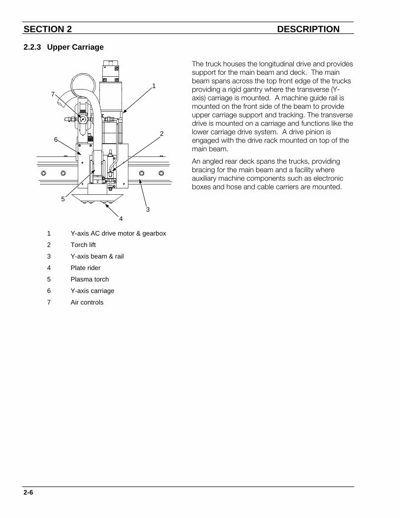
2.2.3 Upper Carriage
3
1
62
5
7
4
The truck houses the longitudinal drive and provides support for the main beam and deck. The main beam spans across the top front edge of the trucks providing a rigid gantry where the transverse (Y-axis) carriage is mounted. A machine guide rail is mounted on the front side of the beam to provide upper carriage support and tracking. The transverse drive is mounted on a carriage and functions like the lower carriage drive system. A drive pinion is engaged with the drive rack mounted on top of the main beam.
An angled rear deck spans the trucks, providing bracing for the main beam and a facility where auxiliary machine components such as electronic boxes and hose and cable carriers are mounted.
1 Y-axis AC drive motor & gearbox
2 Torch lift
3 Y-axis beam & rail
4 Plate rider
5 Plasma torch
6 Y-axis carriage
7 Air controls

SECTION 2 DESCRIPTION
2-7
2.2.4 Operator Controls
Computer Numerical Control The primary operator controls used in the cutting process are on the Vision 1000 control console and Vision LE. Detailed descriptions of the operator controls are in the Operation Section and in the Vision 1000 CNC Operating Instructions, F-14-054, Vision LE Operating Instructions, F-14-177.
Vision 1000
00450
1 2
1.6 MASTER UP
F1 F2 F3 F4 F5 F6
N
XQ
Y+
.:
7(
8)
9
S
IT
J -E
4F
5/
6
K
GZ
MA
0B
1C
2D
3
Vision LE
SECTION 2 DESCRIPTION
2-8
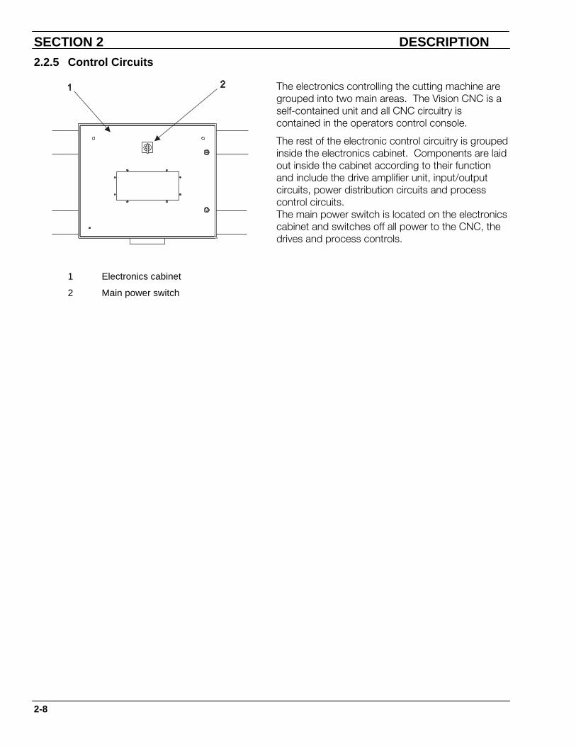
2.2.5 Control Circuits
The electronics controlling the cutting machine are grouped into two main areas. The Vision CNC is a self-contained unit and all CNC circuitry is contained in the operators control console.
The rest of the electronic control circuitry is grouped inside the electronics cabinet. Components are laid out inside the cabinet according to their function and include the drive amplifier unit, input/output circuits, power distribution circuits and process control circuits. The main power switch is located on the electronics cabinet and switches off all power to the CNC, the drives and process controls.
1 Electronics cabinet
2 Main power switch
SECTION 2 DESCRIPTION
2-9
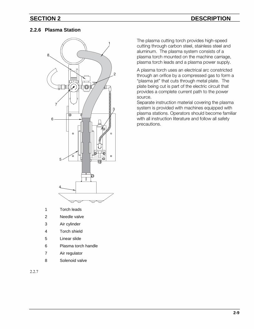
2.2.6 Plasma Station
The plasma cutting torch provides high-speed cutting through carbon steel, stainless steel and aluminum. The plasma system consists of a plasma torch mounted on the machine carriage, plasma torch leads and a plasma power supply.
A plasma torch uses an electrical arc constricted through an orifice by a compressed gas to form a “plasma jet” that cuts through metal plate. The plate being cut is part of the electric circuit that provides a complete current path to the power source. Separate instruction material covering the plasma system is provided with machines equipped with plasma stations. Operators should become familiar with all instruction literature and follow all safety precautions.
1 Torch leads
2 Needle valve
3 Air cylinder
4 Torch shield
5 Linear slide
6 Plasma torch handle
7 Air regulator
8 Solenoid valve
2.2.7

SECTION 2 DESCRIPTION
2-10
2.2.8 Insulation Cutting
Waterjet systems utilize the cutting action of water to further automate the duct cutting process. The Insulation Piecemaker 2 can cut ductwork from galvanized steel with the plasma torch, then cut the insulation layers on the outside of the duct fittings with the waterjet. Both part programs are downloaded into the CNC and one machine and one set of rails is capable of two different processes (thermal and nonthermal) on two different materials. The waterjet station includes the cutting head and a pneumatic slide that lowers the head for cutting and raises it out of the way when not in use.
1 3/8" hose (5000 psi)
2 Waterjet station mounting bracket
3 Adjustable handles
4 Pneumatic cylinder
5 Pneumatic slide
6 Waterjet cutting head
To accommodate different insulation thickness', the station can be moved up or down and locked with adjustable handles. This can be done at the beginning of a cut or anytime a different material thickness is changed.
SECTION 2 DESCRIPTION
2-11
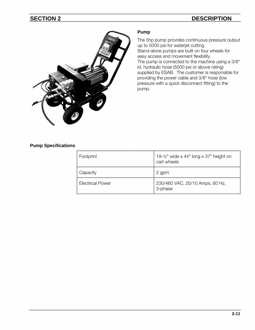
Pump
The 5hp pump provides continuous pressure output up to 5000 psi for waterjet cutting. Stand-alone pumps are built on four wheels for easy access and movement flexibility. The pump is connected to the machine using a 3/8" id. hydraulic hose (5000 psi or above rating) supplied by ESAB. The customer is responsible for providing the power cable and 3/8" hose (low pressure with a quick disconnect fitting) to the pump.
Pump Specifications
Footprint 19-½" wide x 44" long x 37" height on cart wheels
Capacity 2 gpm
Electrical Power 230/460 VAC, 20/10 Amps, 60 Hz, 3-phase

SECTION 2 DESCRIPTION
2-12
This page intentionally left blank.

Contents
3.1 Introduction................................................................................. 3-1
3.2 Installation Checklist ................................................................... 3-2
3.3 Preparation ................................................................................. 3-6 3.3.1 Introduction ..................................................................... 3-6 3.3.2 Prepare Area................................................................... 3-7 3.3.3 Equipment Location ........................................................ 3-8 3.3.4 Grounding ..................................................................... 3-11 3.3.5 Electrical Requirements ................................................ 3-18 3.3.6 Compressed Air Supply ................................................ 3-19 3.3.7 Water Requirements ..................................................... 3-20
3.4 Rail and Gantry Installation....................................................... 3-21 3.4.1 Introduction ................................................................... 3-21 3.4.2 Receiving the Machine.................................................. 3-21 3.4.3 Rail Installation.............................................................. 3-22
3.5 Gantry Installation..................................................................... 3-36
Installation
Contents

PieceMaker 2

3.1 Introduction
The machine installation process is divided into three general phases: preparation, rail and gantry installation and preliminary setup.
It is important to understand which areas are the customer’s responsibility and which areas the ESAB Service Representative will supervise.
Preparation
The preparation phase includes those items that must be prepared before machine arrival. All of these items are the customer’s responsibility.
Rail and Gantry Installation
The rail and gantry installation phase includes rail system installation, placing the machine gantry on rails and connecting supplies to the machine. It is the customer’s responsibility to receive the machine, install the rail system and set the gantry on the rails. However, the ESAB representative will supervise the remaining critical areas of machine installation. The remaining information in this chapter is provided for those customers capable of completing these steps without supervision.
Preliminary Setup
The preliminary setup phase includes setups and adjustments that must be made before operating the machine, but are usually done after the ESAB Service Representative arrives. Some procedures require machine power to be on. In some instances, the customer can complete these items before the ESAB Service Representative arrives.
Section 3 Installation
Introduction Page 3-1

3.2 Installation Checklist
This checklist is a guide to machine installation. For more information on each topic refer to the appropriate subsection.
Complete all items listed before the ESAB Service Representative arrives. He will supervise the remaining critical areas of machine installation.
Review completed items with the service representative before he arrives to avoid any unnecessary delays or service charges.
Completing all items in advance allows the service representative more time to train your operations and maintenance personnel.
When scheduling permits, an onsite pre-installation visit can be arranged. If this is not possible, a pre-installation phone discussion will be arranged. If questions arise during site preparation, call the Technical Service Department.
Item Description
Prepare Area • Check for minimum clearance between equipment and any wall and/or overhead obstruction per OSHA.
• Check easy access for maintenance.
• Check space required for efficient material flow.
• Plan location of fume removal system (optional for downdraft table) including ductwork and blower.
Equipment Location
• Determine machine service inlet location.
Piecemaker 2
Page 3-2 Installation Checklist
• Service inlets for supply gas, air and water can be located on either side of the machine depending on the installation requirements. Each inlet is labeled by the service intended and uses different hardware to prevent cross connections.
• Supply gas for plasma is supplied through a red hose and notched connectors having left-hand threads.
• Determine location for water purification system (for waterjet process).
• Refer to the Safety Section and additional safety literature supplied or recommended to establish the safest conditions possible for personnel and equipment.
Prepare Foundation
• Make foundation plan drawings. Include location of machine, rails, air, water and power supplies, ground rod, utility trench (if desired), fume removal system and water drain pipe for cutting table.
• Install new foundation (if required), utility trench and ground rod.
Electrical Power Needs
• Electrical service is distributed through steel tube conduits built into the deck structure for protection against an environment that could damage conductors and create hazardous conditions.
• Determine electrical power requirements for cutting machine, plasma power supply and water pump. Refer to the installation drawings to determine power required by each piece of equipment.
• All wiring to the cutting machine, grounding protection and optional items must meet or exceed National Electrical Code (NEC) standards and any applicable local ordinances.
• Design and install electrical supplies, including power drops, conduit and breakers or fused disconnects, within five meters of machine service inlet (center of powertrack).
Section 3 Installation
Installation Checklist Page 3-3

Compressed Air Supply
• Specify new air system or modifications to existing system to meet requirements for machine and plasma system.
• Install new air system, regulators, filters, shutoff valves and piping within five meters of the machine service inlet.
• Entire air system must be free of water, oil and particulate matter before operating.
Gas Supplies • Determine maximum cutting requirements and specify the gas system accordingly.
• Consult with local gas supplier for assistance with gas supplies and regulators.
• Consult specific plasma manuals for gas requirements.
• Check requirements for torch types used on your machine.
• Gas supply specifications must meet or exceed all OSHA requirements and local regulations.
• Install the gas supply system, evaporators and regulators, shutoff valves and piping to within five meters of machine service inlet.
Install Rail System • Install rail system to tolerances listed in this manual.
Cutting Table • Install cutting table per installation drawings.
• Install all piping to the cutting table including the water supply and drainpipe.
• Install fume removal system including ductwork and blower.
DNC Cable • Install fiber optic cables for DNC connection.
Piecemaker 2
Page 3-4 Installation Checklist
Grounding • Read “Cutting Machine Grounding” (ESAB Part No. F14074), included with the pre-installation package, in its entirety before starting the installation process.
• Install a good earth ground rod for the cutting machine, rail system and cutting table, within 10 ft (3m) of star ground.
• Determine location of the star ground point on the cutting table and on the machine chassis.
• Earth ground rod must be connected to the star point on the cutting table(s).
• All electrical enclosures must be bolted to machine chassis.
• Machine chassis must be grounded to the star point on the cutting table.
• Rails must be grounded to the cutting table at all four corners.
• Plasma ground must be connected to the start point on the cutting table.
Section 3 Installation
Installation Checklist Page 3-5
3.3 Preparation
3.3.1 Introduction
This section discusses the installation preparation phase. These items require preparation well in advance of actual machine installation. Perform topics in the order they are arranged.
Some items may require major facility rework to accommodate the machine. Complete all applicable items before the ESAB Service Representative arrives. Start preparations as soon as machine is purchased.
Piecemaker 2
Page 3-6 Preparation

3.3.2 Prepare Area
Before the cutting machine delivery, prepare a safe, efficient cutting area with an adequate foundation and adequate gas, electrical and water systems.
The area must provide:
• A safe work environment, including proper air circulation, ventilation, noise protection and other conditions, depending on cutting machine options.
• Recommended electrical power, gas, oxygen, air, water and water drainage systems as determined by machine and options purchased.
• A separate earth ground rod to ensure safe operation and reduce RFI problems. Refer to ESAB manual “General Guidelines for Cutting Machine Grounding” (Part # F14-074).
• Material handling equipment to carry work pieces and parts to and from the cutting machine in an efficient and convenient manner.
• Sufficient clearance around and above the gantry for safe and efficient operation.
• A good foundation with protection against vibration and mechanical shock.
You should be familiar with the following sources on cutting operations and plasma arc cutting before preparing your cutting machine area:
U.S.A. Standard ANSI Z 49.1-1983 “Safety in Welding and Cutting.”
National Fire Protection Association Bulletin No. 51B “Standard for Fire Prevention In the Use of Cutting and Welding Processes.”
American Welding Society, Inc., Bulletin No. AWS C5.2-83 “Recommended Practices for Plasma Arc Cutting.”
Section 3 Installation
Preparation Page 3-7

3.3.3 Equipment Location
Determine location of the rail system and the plasma power supply before installation.
All hoses and cables are conducted from a fixed point on the floor to the moving machine gantry via a powertrack cable carrier system.
Since all hoses and cables enter the powertrack at the center of its travel, all gas and electrical supplies and auxiliary equipment should be located near the center of the rail system. Sufficient cables and hoses are supplied to reach five meters from the termination of the powertrack. Take into account vertical runs and obstructions when measuring the five meters. See drawing below for a typical layout of a machine and its auxiliary equipment.
Locate the power disconnects and the air supply readily accessible by the operator.
Fume Removal System
The fume removal system is an optional system that removes fumes generated by the plasma cutting process. The fume collection boxes, included as part of the downdraft table, terminate in a 16" (406mm) duct. The customer is responsible for installing the appropriate ducting to connect these boxes to a fume removal blower. Consider the amount of clearance needed for the ductwork required by the exhaust system. The standard exhaust system includes all ductwork from the cutting table to the air connection at the damper. The connecting duct is 16" (406mm) diameter. We recommend installing the blower on the back or left side of the machine. The fume removal blower must be rated for at least 2100 CFM.
Piecemaker 2
Page 3-8 Preparation
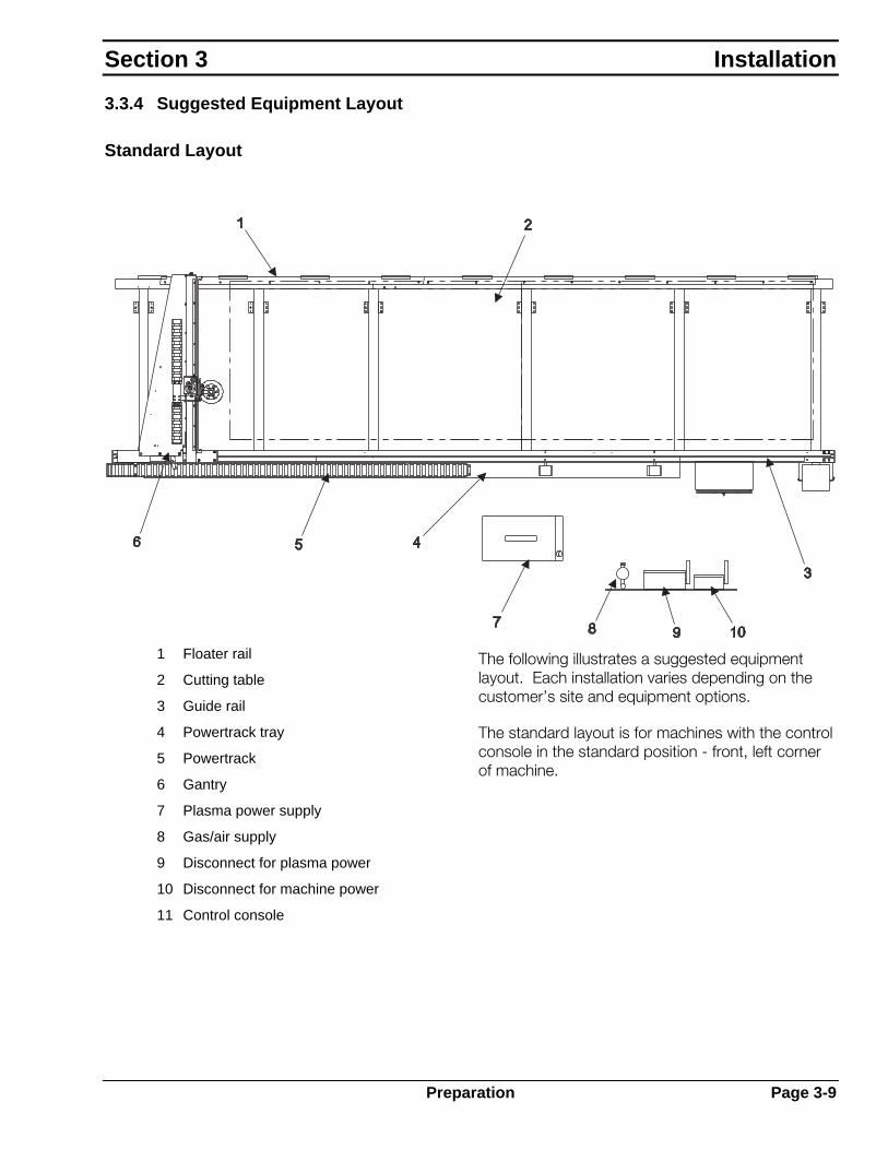
3.3.4 Suggested Equipment Layout
Standard Layout
1 Floater rail
2 Cutting table
3 Guide rail
4 Powertrack tray
5 Powertrack
6 Gantry
7 Plasma power supply
8 Gas/air supply
9 Disconnect for plasma power
10 Disconnect for machine power
11 Control console
The following illustrates a suggested equipment layout. Each installation varies depending on the customer’s site and equipment options.
The standard layout is for machines with the control console in the standard position - front, left corner of machine.
Section 3 Installation
Preparation Page 3-9

3.3.5 Foundation Requirements
The following guidelines apply to all cutting machine installations:
• Situate entire rail system on a single slab of reinforced concrete, free from severe vibration and major cracks.
• Floor should be at least 6" (152mm) thick.
• Floor must not have any severe height changes, and must not have an overall height change greater than 2" (50mm).
• If new concrete is needed to meet these specifications, allow sufficient time for concrete to cure before installing rails.
• Special floor pads or foundations may be needed to isolate the gantry from vibration created by nearby equipment.
• Soil under the concrete floor must settle completely so the machine load and the floor do not cause further settling.
Piecemaker 2
Page 3-10 Preparation

3.3.6 Grounding
Machine grounding is an important part of installation. The most difficult part of the grounding process is designing and installing a low impedance earth ground rod. However, the better the Earth ground rod, the less chance of having EMI (Electromagnetic Interference) problems after installation is complete.
While the National Electric Code addresses grounding for fire prevention and short circuit protection, it does not address equipment protection and EMI noise reduction. Therefore, this manual presents more stringent requirements addressing these special problems.
Electric shock hazard.
Can shock, burn or cause death.
Machine must be properly grounded before put into service.
Improper grounding can damage machine and electrical components and voids certain warranty provisions.
Machine must be properly grounded before put into service.
The cutting table must be properly grounded to a good Earth ground rod.
Section 3 Installation
Preparation Page 3-11

3.3.6.1 Grounding Overview
1 Electrical ground
2 Plasma power supply
3 Cutting table
4 Earth ground rod
5 Rails
6 Flow control
7 Plumbing box
8 AHC box
9 CNC enclosure
10 Machine chassis
11 Machine star ground
12 Cutting table star ground
Grounding is accomplished by connecting all the system components to a single star point on the cutting table, which is then connected to the Earth ground rod. The rail system is also electrically connected to the cutting table through mounting bolts. The following connections need to be made:
• All electrical enclosures bolted to machine chassis.
• Machine chassis grounded to star point on cutting table.
• Rails grounded to cutting table at all four corners.
• Plasma ground connected to star point on cutting table.
• Earth ground rod connected to star point on cutting table.
Piecemaker 2
Page 3-12 Preparation

3.3.6.2 Grounding System The ground system consists of five main
components: plasma ground, ground rod, utility power electrical ground, cutting machine chassis ground and rail system safety ground. Each element is important for creating a complete ground system. Make provisions for each element during installation, as shown below.
1 3-phase electrical supply must include electrical ground
2 Single ground rod connected to table (1/0)
3 Machine chassis ground (6 Ga.) connected to table
4 Rails grounded to table at all four corners (1/0)
5 Plasma positive (+) connected to table (1/0)
Notes
1. Use 1/0 AWG 600 volt welding cable for all plasma grounds.
2. Use 6 AWG stranded wire to ground machine chassis.
3. Use cutting table as the star ground point.
4. Use a single ground rod located within 10 ft (3m) of star ground. Resistance to the earth ground should be less than three ohms. Measure as shown for earth ground test.
5. The plasma power supply housing must be grounded to main power distribution ground. Wire size must comply with local electrical code.
Section 3 Installation
Preparation Page 3-13

Make sure all interconnections make good electrical contact. Good electrical contact requires connections that are made with bare metal to metal contact and are very tight and protected from rust and corrosion. When connecting cable lugs to any metal surface, use a grinder or wire wheel to clean all paint, rust and dirt from surface. Use an electrical joint compound (such as ESAB Part No. 73585980) between cable lugs and metal surfaces to prevent future rust and corrosion. Use the largest size bolts, nuts and washers possible and tighten fully. Use lock washers to ensure connections stay tight.
Plasma Ground
The return path ground cable is the first and most important element of the ground system because it completes the plasma current path. Solid, low impedance and well-maintained electrical connections are necessary. The plasma cutting current is generated by the plasma power supply. Welding cables carry this current from the negative (-) connection on the plasma power supply to the torch, where it arcs to the work piece on the cutting table. The current path must be closed so the current can easily return to its source. This is done by connecting the cutting table to the positive (+) connection on the plasma power supply.
If the return path ground cable is not connected, the plasma system will not work because the arc cannot establish between the torch and the work piece. If cable is connected but connections have a very high resistance, the arc current is limited causing dangerous voltage levels between system components.
Piecemaker 2
Page 3-14 Preparation
Ground Rod (Plasma System Safety Ground)
The ground rod serves several important purposes. It provides frame voltage for personnel safety by ensuring there are no potential differences between the system components and the building components. It provides a stable signal reference for all digital and analog electrical signals on the cutting machine. It helps control RF (Radio Frequency) emissions and other EMI (Electro-Magnetic Interference). It also provides a discharge path for short circuits and high voltage spikes, such as those caused by lightening.
The ground rod can be optimized in two ways: length and diameter. The longer the ground rod, the better the connection. The larger the diameter, the better the connection. The standard ground rod specification is 1" (25mm) diameter rod, 20 ft (7m) long.
Electrolytic Ground Rods
A grounding expert may suggest using an electrolytic ground rod with conditioned backfill. Although expensive, this option gives the best possible ground connection. To install one of these rods, excavate or drill the ground, install rod, then backfill around rod with conditioned soil. The result is a very low impedance earth ground that maintains itself for the cutting machine lifetime.
Multiple Ground Rods
Do not use multiple ground rods. While installing multiple rods may improve a safety or lightening ground, they offer no advantage for EMI reduction and can cause more problems than they are worth. For more information, refer to form F-14-074, General Guidelines for Cutting Machine Grounding.
Utility Power Electrical Ground
The utility power electrical ground must accompany all 3-phase and single-phase power feeds. This electrical ground provides the proper reference for all incoming power. Failure to provide this ground is a violation of some electrical codes and a serious safety hazard.
Section 3 Installation
Preparation Page 3-15
Connect the electrical ground to the appropriate terminal inside the plasma power supply. Size wire according to local electrical codes.
Cutting Machine Chassis Ground
Because all cutting machine electrical enclosures and shields are connected to the chassis, proper functioning of the electronic systems depends on the chassis being grounded. The cutting machine chassis ground connects the chassis of the cutting machine gantry to the plasma system star ground point. This is usually a 6-gauge stranded copper wire, connected to the cutting table. This wire connects all electrical and chassis grounds on the machine to the ground rod. This wire is supplied with the cutting machine and is connected during machine installation.
Rail System Safety Ground
The rail system safety ground ensures the entire rail is at ground potential, eliminating any possible shock hazard and providing backup for the machine chassis ground in case of a plasma current short circuit.
Piecemaker 2
Page 3-16 Preparation

Earth Ground Test
Electric shock hazard.
Can shock, burn or cause death.
Do not touch the ground rod while power is being applied to the light bulb.
To test the earth ground, connect a 100-Watt light bulb between 115 VAC HOT and the cutting machine’s ground rod. Connect a digital voltmeter between AC NEUTRAL from the same source and ground rod.
The meter displays the voltage between AC NEUTRAL and the ground rod, which is equal to the resistance in ohms between these two points. The meter must read three volts or less for plasma machines.
1 100 watt lamp
2 AC setting (three volts or less for plasma)
3 115 VAC (Hot)
4 AC Neutral
5 Ground rod
The ideal condition between the ground rod and the electrical ground is three ohms or less. However, this value may be difficult to achieve.
To reduce ground resistance, take one of the following steps:
1. Increase rod length and/or diameter.
2. Condition soil surrounding ground rod by adding moisture or salt.
3. Use an electrolytic ground rod with conditioned backfill.
Section 3 Installation
Preparation Page 3-17

3.3.7 Electrical Requirements
Electrical requirements for a cutting machine installation fall into two categories - power for cutting machine gantry and power for auxiliary equipment. In general there is only one power cable supplying power to the gantry and any auxiliary equipment mounted on the gantry will draw power from that cable. However, any auxiliary equipment not mounted on the gantry requires separate input power disconnects supplied by the customer.
This section covers only the input power requirement for the cutting machine gantry, not auxiliary equipment. For auxiliary equipment power requirements, see the manual for that piece of equipment.
Contact your local power company to provide proper electrical service and fusing.
Voltage Amperage Recommended Fuses
Gantry Power 120 VAC, single-phase, 60 Hz
20 Amps 20 Amp, Time-Delay
1 Fused disconnect box (customer supplied)
2 Customer’s AC power
3 Power ground
4 Input power cable (supplied w/machine)
5 120 VAC machine power
6 Machine chassis
Piecemaker 2
Page 3-18 Preparation
3.3.8 Compressed Air Supply
This cutting machine requires a source of clean, dry regulated air with the following specifications:
Line Pressure Supply Connection
90 psi (6.2 bar) ½" NPT Female
Keep air system free of water, oil, and particulate matter. Failure to keep air system clean may cause damage to mechanical components.
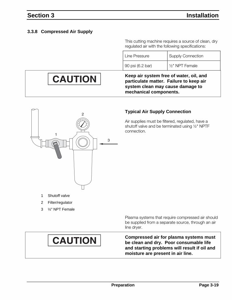
Typical Air Supply Connection
Air supplies must be filtered, regulated, have a shutoff valve and be terminated using ½" NPTF connection.
1 Shutoff valve
2 Filter/regulator
3 ½" NPT Female
Plasma systems that require compressed air should be supplied from a separate source, through an air line dryer.
Compressed air for plasma systems must be clean and dry. Poor consumable life and starting problems will result if oil and moisture are present in air line.
Section 3 Installation
Preparation Page 3-19

3.3.9 Water Requirements
The water requirements for this machine are listed below. The water input line must be PVC, rubber or stainless steel with manual shutoff valve. Other auxiliary equipment such as water recovery and conditioning systems, use water in closed circulating systems and do not require an external water source.
Water Requirements for Cutting Machine
Flow Rate Line Pressure Supply Connection
Cutting Head 5,000 psi 3/8" S/S, ¾"–16 Female (ESAB supplies plumbing from pump to cutting head) 1
Pump Cutting Water Inlet Up to 2 GPM 5 – 30psi ½" PVC Pipe, ½" NPT Female
Cutting Table Water 2 50 psi (3.4 bar) 1" water hose, 1" NPT Female
1 Install the water filtration system with ¾" NPT connections.
2 Most cutting tables are designed to automatically refill when water level is low. This water input connection is usually piped. Refer to the installation information provided with your table.
Contact your local water department or authority to obtain possible restrictions regarding the disposal of cutting table water.
1 Regulated supply
2 Shutoff valve
3 ½" NPT female
Typical Service Water Supply Connections
Water supplies must have a shutoff valve and be terminated using ½" NPTF connection.
Piecemaker 2
Page 3-20 Preparation

3.4 Rail and Gantry Installation
3.4.1 Introduction
The rail and gantry installation phase includes all necessary steps from receiving machine to connecting supplies and cables. Customer must complete all items in this section before the ESAB representative arrives.
3.4.2 Receiving the Machine
Upon receiving machine, carefully open and inspect all crates and cartons for shipping damage. Contact your shipper immediately if any damage is evident.
As you unpack machine, carefully inventory all parts against the packing list. Immediately report any discrepancies.
Section 3 Installation
Rail and Gantry Installation Page 3-21

3.4.3 Rail Installation
3.4.3.1 Introduction
This section provides a basic guide to completing rail and machine installation. When possible, the machine is shipped pre-assembled, requiring minimal installation work. However, longer rail systems or special shipping requirements may require machine to be shipped disassembled. In this case, assemble and install rails as shown in this section.
3.4.3.2 Rail Installation Tolerances
Install rail system to the following tolerances. Although very strict, these tolerances are attainable using the tools and techniques described below. Achieving these tolerances ensures accurate and repeatable performance from your ESAB cutting machine.
• Guide rail straight to within ± 0.005" (0.13mm) over entire length of rail.
• Track gauge must be within ± 0.031" (0.78mm) over entire length of rail system.
• Top surface of guide rail level within ± 0.002 " (0.05mm) per every 10 ft (3.3m) of longitudinal travel.
• Top of floater rail track bar level within ± 0.031" (0.78mm) over entire rail system.
• Top surface of rails level in the transverse direction within ± 0.002" (0.05mm).
• Top and side edges of rail joints should be flush with no gaps between rail ends.
Piecemaker 2
Page 3-22 Rail and Gantry Installation

3.4.3.3 Area Preparation
Clear out machine installation area. Determine area size from machine outline drawing below. Situate entire rail system on a single slab of reinforced concrete, free from severe vibration and major cracks. Floor should be at least 6" (152mm) thick. Floor must not have any severe height changes and must not have an overall height change greater than 2" (50mm). If new concrete must be poured to meet these conditions, allow enough time for concrete to cure before rail installation.
Section 3 Installation
Rail and Gantry Installation Page 3-23

3.4.3.4 Rail Installation Tools
The following tools and materials are needed to complete rail installation:
1. Precision spirit level, 14" (357mm) long, graduated at 0.0005" (0.013mm) per ft.
2. Small precision machinists’ level with ground vial, about 4" (102mm) to 6" (152mm) long, graduated at 0.005" (0.13mm) per ft.
3. Fifty-foot spool of steel music wire, about 0.010" (0.25mm) to 0.012" (0.30mm) in diameter.
4. Three precision spacers. Square key stock, or machine tool bits may be used. Spacers may be about ½" (13mm) thick by 2" (50mm) long but all three must have the same thickness within 0.0005" (0.013mm).
5. A 3/8" (9.5mm) drive socket wrench, including long ratchet handle (breaker bar), 8" (203mm) extension and metric sockets. Air or electric impact tools help speed installation.
6. Metric and inch combination wrenches.
7. At least two “C” clamps suitable for clamping music wire to rail sides. Requires 3" (75mm) opening capacity. Kant Twist toggle-type parallel clamps are recommended.
8. At least two “C” clamps suitable for clamping the gauge rack to drive rack to set proper rack joints. Require 3" (75mm) opening capacity.
9. Steel measuring tape 100 ft (33m) long.
10. Chalk line with chalk.
11. Supply of cleaning rags.
12. Nonflammable, non-toxic cleaning solvent to remove rust preventative on rails and rack.
Piecemaker 2
Page 3-24 Rail and Gantry Installation

13. Large hammer drill capable of drilling ¾" (19mm) diameter holes in concrete.
14. Forklift or other means of lifting and moving rail sections into position. Always lift rail sections from bottom. If rail sections are lifted by overhead crane, use nylon straps to prevent damage to machined surfaces.
3.4.3.5 Clean Rails
• Remove rails from shipping crates and clean off rust preventative coating put on at factory. Use a nonflammable, non-toxic solvent. Be very careful when handling rails to prevent damage to machined surfaces. Take safety precautions when moving rails to prevent injury to personnel.
• Clean tongue and groove at rail joint. Clean out any burrs or debris from all machined surfaces.
• Clean out any burrs or debris from all rail-mounting holes.
• Clean flat bar strip on the floater rail.
Section 3 Installation
Rail and Gantry Installation Page 3-25
3.4.3.6 Layout Rail Location Chalk Lines
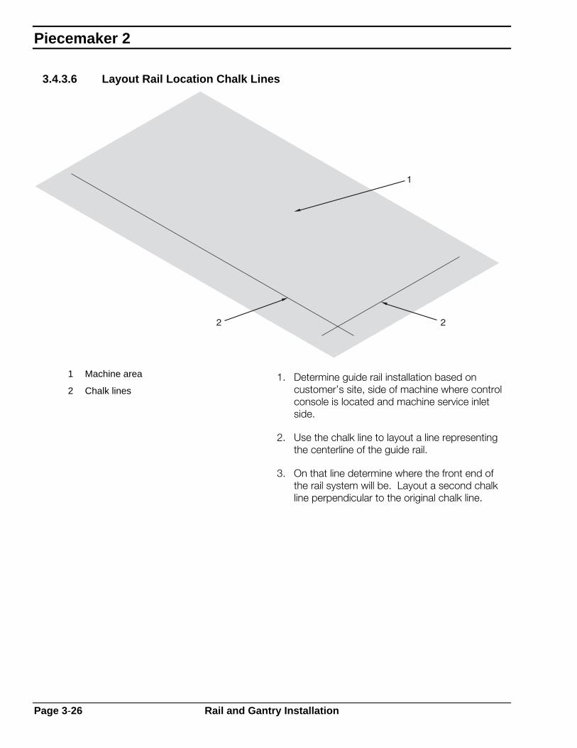
1 Machine area
2 Chalk lines 1. Determine guide rail installation based on
customer’s site, side of machine where control console is located and machine service inlet side.
2. Use the chalk line to layout a line representing the centerline of the guide rail.
3. On that line determine where the front end of the rail system will be. Layout a second chalk line perpendicular to the original chalk line.
Piecemaker 2
Page 3-26 Rail and Gantry Installation

3.4.3.7 Assemble Rail System
Assemble rails in three steps:
1. Set cradles in place.
2. Set rails on cradles.
3. Align and level rails.
1 Rail cradles
2 Chalk lines
Section 3 Installation
Rail and Gantry Installation Page 3-27

Setting the Cradles In Place
Set each cradle in its location along the chalk line for each rail. Line up anchor boltholes directly over chalk line.
Place each cradle as shown so guide rail is mounted on the straight, or left-hand pedestal.
Install an M12 x 30mm hex head cap screw and M12 hex jam nut in each cradle jacking bolthole. Make sure these bolts do not protrude through top pad of cradle.
1 M12 jam nuts
2 M12 x 30mm bolts
Setting the Rails On The Rail Cradles
After cleaning rails, place T-rails on top of the taller cradles, on the left-hand side of the machine. This is the guide rail. Place floater rail tube on the shorter cradles, on the right hand side of machine. On the guide rail, mount the rack on the outside of the rail. On the floater rail, mount the flat bar track toward the outside of the tube.
1 Guide rail
2 Rack
3 Floater rail
4 Floater tube rail
5 Flat bar track
Piecemaker 2
Page 3-28 Rail and Gantry Installation

Level Rail Cradles
After assembling the rail to the cradles, roughly check for straightness and level. Do this before anchoring the rails to simplify leveling and straightening.
Use the precision spirit level to check the slope of the rail between each cradle. Add shim plates where necessary to bring tops of all rail cradles within 1/8" (3mm), or to compensate for gaps between cradle and floor.
The assembled rail appears as shown below. Shown is a 16 ft (5.2m) rail system. The 25 ft (8.2m) rail system consists of a 16 ft (5.2m) rail and a 9 ft (3m) extension.
1 Floater rail
2 Chalk lines
3 Guide rail
4 Drive rack mounted to outside of rail
Section 3 Installation
Rail and Gantry Installation Page 3-29

Aligning and Leveling the Rails
If rail cradles were aligned and leveled properly, this step should be a quick check of rails. However, you must verify the rails are within the adjustment range of the rail cradles before drilling anchor holes.
With rail system completely assembled, but not yet anchored to the floor, complete a rough alignment of the entire rail system. Tighten all rail mounting hardware as you go.
1. Verify rail system position.
2. Using a nylon string stretched over the length of guide rail, roughly straighten rail by moving cradles until rail is roughly straight, within ±1/16" (1.5mm).
3. Use the precision spirit level to check the slope of the top surface of the rail between each rail pad location. Add shim plates, if necessary, to raise all rail pad locations within ±1/8" (3mm).
4. Use the same techniques to adjust the floater rail, so it is straight and level within 1/8" (3mm).
3.4.3.8 Drill Floor & Anchor Rails
With entire rail system straight, level and parallel within 1/8" (3mm) drill the floor and install anchors.
Different types of anchors and methods of anchoring base plates to the floor may be used, but it is the customer’s responsibility to provide a solid machine foundation that will not allow the rail system to move or become misaligned during operation. Anchor bolts must reach at least 4" (102mm) into the floor.
1 Anchor bolt
2 4" minimum 1. Starting at the front of the guide rail, drill both
anchor holes for the first cradle. Use the anchor holes in the base plate as a template and drill through the holes without moving the rail assembly. Install all four anchors, washers and nuts. Finger tighten nuts on anchor bolts.
2. Move to the next cradle and repeat procedure. Do not move rail system while drilling floor.
Piecemaker 2
Page 3-30 Rail and Gantry Installation

3. Complete entire guide rail. Double check the rough level, straightness and rail gauge dimension before moving to the non-guide rail.
4. Check the rail gauge dimension between guide and non-guide rails. Make necessary adjustments to position of cradles to maintain correct gauge dimension ± 1/16" (1.5mm).
5. Starting at front of floater rail, drill all four anchor holes for the first cradle. Install all four anchors, washers and nuts. Finger tighten nuts on anchor bolts.
6. Move to next cradle and repeat procedure. Do not move rail system while drilling floor.
Section 3 Installation
Rail and Gantry Installation Page 3-31

3.4.3.9 Final Align & Level
Final Straight
Using music wire stretched over the length of the rail, straighten rail to tolerance listed earlier in this chapter. Start with the guide rail.
1. Use a C-clamp to clamp music wire to the side of the rail at each end. Clamp a precision spacer between the music wire and the side of rail to establish a precise distance between rail and wire. Stretch wire very tight. Verify that wire is flat against spacer by inserting a third spacer right next to the clamp.
2. Using the third precision spacer, check distance between the music wire and the side of rail at each cradle location over entire length of rail.
3. Tap side of the rail base with hammer to move rail from side to side. To reach the straightness tolerance, adjust rail until the gap between spacer and wire is within one-half the wire width when using 0.010" (0.25mm) wire. Use a magnifying glass to verify.
4. Once guide rail is straight, fully tighten all anchor bolts and recheck straightness. Make final level adjustments and recheck straightness before moving to floater rail. Adjusting rail elevation slightly disturbs the rail straightness.
1 Rail
2 Spacer
3 Wire
A Not to exceed ½ width of wire
B 0.010" wire
Piecemaker 2
Page 3-32 Rail and Gantry Installation
Final Level
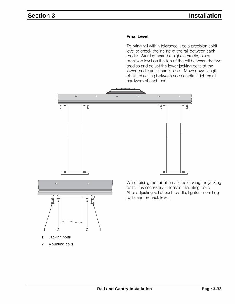
To bring rail within tolerance, use a precision spirit level to check the incline of the rail between each cradle. Starting near the highest cradle, place precision level on the top of the rail between the two cradles and adjust the lower jacking bolts at the lower cradle until span is level. Move down length of rail, checking between each cradle. Tighten all hardware at each pad.
While raising the rail at each cradle using the jacking bolts, it is necessary to loosen mounting bolts. After adjusting rail at each cradle, tighten mounting bolts and recheck level.
1 Jacking bolts
2 Mounting bolts
Section 3 Installation
Rail and Gantry Installation Page 3-33
While adjusting rail elevation, the top surface of the rail must be kept level in the transverse direction. Use the small precision level placed on the top surface of the rail to adjust jacking bolts as necessary.
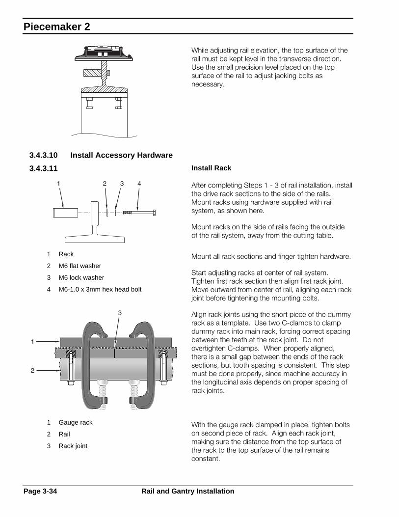
3.4.3.10 Install Accessory Hardware
3.4.3.11 Install Rack
After completing Steps 1 - 3 of rail installation, install the drive rack sections to the side of the rails. Mount racks using hardware supplied with rail system, as shown here.
Mount racks on the side of rails facing the outside of the rail system, away from the cutting table.
1 Rack
2 M6 flat washer
3 M6 lock washer
4 M6-1.0 x 3mm hex head bolt
Mount all rack sections and finger tighten hardware.
Start adjusting racks at center of rail system. Tighten first rack section then align first rack joint. Move outward from center of rail, aligning each rack joint before tightening the mounting bolts.
Align rack joints using the short piece of the dummy rack as a template. Use two C-clamps to clamp dummy rack into main rack, forcing correct spacing between the teeth at the rack joint. Do not overtighten C-clamps. When properly aligned, there is a small gap between the ends of the rack sections, but tooth spacing is consistent. This step must be done properly, since machine accuracy in the longitudinal axis depends on proper spacing of rack joints.
1 Gauge rack
2 Rail
3 Rack joint
With the gauge rack clamped in place, tighten bolts on second piece of rack. Align each rack joint, making sure the distance from the top surface of the rack to the top surface of the rail remains constant.
Piecemaker 2
Page 3-34 Rail and Gantry Installation
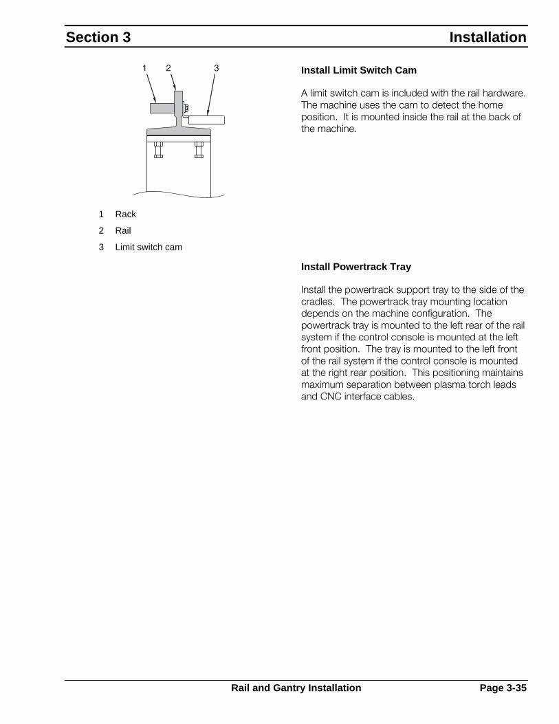
Install Limit Switch Cam
A limit switch cam is included with the rail hardware. The machine uses the cam to detect the home position. It is mounted inside the rail at the back of the machine.
1 Rack
2 Rail
3 Limit switch cam
Install Powertrack Tray
Install the powertrack support tray to the side of the cradles. The powertrack tray mounting location depends on the machine configuration. The powertrack tray is mounted to the left rear of the rail system if the control console is mounted at the left front position. The tray is mounted to the left front of the rail system if the control console is mounted at the right rear position. This positioning maintains maximum separation between plasma torch leads and CNC interface cables.
Section 3 Installation
Rail and Gantry Installation Page 3-35
3.5 Gantry Installation
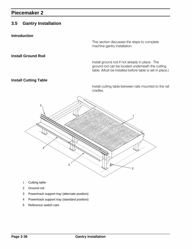
Introduction
This section discusses the steps to complete machine gantry installation.
Install Ground Rod
Install ground rod if not already in place. The ground rod can be located underneath the cutting table. (Must be installed before table is set in place.)
Install Cutting Table
Install cutting table between rails mounted to the rail cradles.
1 Cutting table
2 Ground rod
3 Powertrack support tray (alternate position)
4 Powertrack support tray (standard position)
5 Reference switch cam
Piecemaker 2
Page 3-36 Gantry Installation
3.5.1.1 Install Machine Gantry
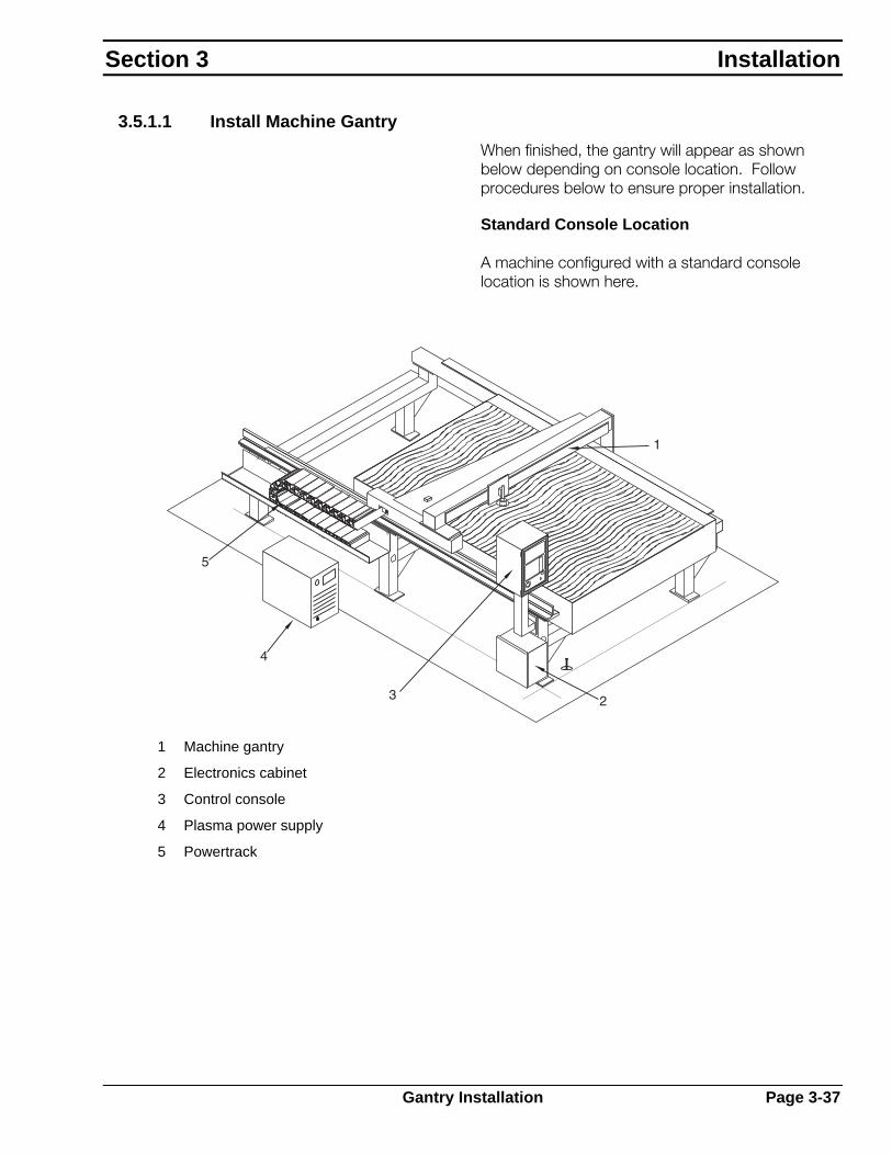
When finished, the gantry will appear as shown below depending on console location. Follow procedures below to ensure proper installation.
Standard Console Location
A machine configured with a standard console location is shown here.
1 Machine gantry
2 Electronics cabinet
3 Control console
4 Plasma power supply
5 Powertrack
Section 3 Installation
Gantry Installation Page 3-37

Alternate Console Location
A machine configured with an alternate console location is shown here.
1 Machine gantry
2 Powertrack
3 Electronics cabinet
4 Plasma power supply
5 Control console
Piecemaker 2
Page 3-38 Gantry Installation

3.5.1.2 Setting Machine On the Rails
For the most part, the machine is shipped pre-assembled and ready to be placed on the completed rail installation. The following procedures are a guide for completing that step of machine installation.
1. Follow your plant safety guidelines. DO NOT allow unauthorized personnel near machine during lifting and transporting.
2. Remove all obstacles from transporting path of machine to installation site.
3. If lifting from overhead make sure slings or chains DO NOT hit or apply pressure to machine components, i.e. cross rails, carriage, etc. If lifting with forklift, spread forks to widest spacing available to provide maximum lifting support. Forks should be blocked so support is distributed along beam and deck. DO NOT allow forks to contact machined rails on front of beam.
4. After attaching lift devices at determined points for balance, and before transporting machine, make a limited height (few inches) test lift to determine proper balance. Make adjustments to lift points as required to achieve balance.
5. Before lifting and transporting machine, secure cross carriage to prevent motion during lifting.
Section 3 Installation
Gantry Installation Page 3-39

6. Before setting the machine on rails, disengage the drive pinions and adjust eccentric side guide bearings out to maximum clearance. This assures drive pinions, gearboxes, bearings and rails are not damaged when machine is lowered onto rails.
7. Remove floater rail retainer to allow floater side bearing to be set on track bar.
8. As machine is lowered onto rails, check the following:
• Wheels must set down on rail surface.
• Side guide rollers must clear side edges of rails.
• Make sure drive pinions are not jammed against racks.
1 Drive pinion pulled out
2 Eccentric bearing adjusted out
Piecemaker 2
Page 3-40 Gantry Installation

9. Once machine is resting on the rails, place a precision spirit level on top of the beam to verify machine is level. Adjust the wheel on the floater side of the machine to level beam if necessary.
1 Precision spirit level
2 Adjustable wheel
Section 3 Installation
Gantry Installation Page 3-41

Side Guide Bearings
The left side truck is designated as the “guide” truck equipped with side guide bearings on each side of the rail. These bearings keep the truck straight on the rail. The bearing is mounted on a fixed shaft outside the rail. On the inside of the rail, bearings are mounted on eccentric spacers that allow space between the bearings to be adjusted. During installation, set these adjustable bearings to the proper clearance.
1. Carefully push machine up and down rail system until both straight bearings are contacting the rail. Check for rail contact by trying to turn bearing by hand.
2. Once both straight bearings are in contact with the rail, loosen bolt in the eccentric spacer.
3. Turn eccentric spacer in toward rail.
4. Using a 0.005" (0.13mm) shim, or feeler gauge, adjust eccentric until bearing applies pressure to shim.
1 Fixed bearing
2 Bearing
3 Eccentric bushing
4 Shoulder bolt
5. Tighten bolt while holding eccentric spacer. Roll machine off shim material.
6. When set properly, only one bearing will contact rail at any time, the other bearing has a maximum 0.003" (0.07mm) to 0.005" (0.13mm) clearance.
Piecemaker 2
Page 3-42 Gantry Installation

Contents
4.1 Introduction................................................................................. 4-1
4.2 Control Console.......................................................................... 4-2 4.2.1 Principles of Operation.................................................... 4-3 4.2.2 Basic Windows................................................................ 4-4 4.2.3 Manual Controls.............................................................. 4-6
4.3 Basic Operating Procedure......................................................... 4-7
4.4 Machine Power ........................................................................... 4-8 4.4.1 Power On ........................................................................ 4-8 4.4.2 Power Off ........................................................................ 4-9
4.5 Homing the Machine................................................................. 4-10
4.6 Downloading Programs ............................................................ 4-11
4.7 Moving the Machine.................................................................. 4-12
4.8 Station Selection....................................................................... 4-13
4.9 Running Programs.................................................................... 4-14
4.10 Timers and Process Parameters .............................................. 4-16
4.11 Plasma Operation..................................................................... 4-17 4.11.1 Introduction ................................................................... 4-17 4.11.2 Setup............................................................................. 4-18 4.11.3 Process Parameters ..................................................... 4-19 4.11.4 Operator Controls ......................................................... 4-20 4.11.5 Automatic Operation ..................................................... 4-21 4.11.6 Manual Operation ......................................................... 4-22
4.12 Insulation Cutting Operation ..................................................... 4-24 4.12.1 Introduction ................................................................... 4-24 4.12.2 Setup............................................................................. 4-25 4.12.3 Timers ........................................................................... 4-26 4.12.4 Operator Controls ......................................................... 4-27 4.12.5 Automatic Operation ..................................................... 4-28 4.12.6 Manual Operation ......................................................... 4-29
Operation
Contents

PieceMaker 2

4.1 Introduction
This chapter provides operating instructions for the PieceMaker 2 Shape Cutting Machine and setup and operating procedures for cutting processes normally used on this machine. For detailed information on the Vision Computer Numerical Control (CNC) operation, refer to the Vision CNC operation manual. For information on writing part programs for the Vision CNC, refer to the Programming Instructions for the Vision CNC, Form F-14-082. For detailed instructions on the operation of plasma equipment, refer to the appropriate instruction manuals.
A shape cutting machine requires a certain amount of preliminary setup before the actual operating process. The information in this chapter, combined with information contained in the literature for specific equipment (regulators, torches, nozzles, marker, etc.) provides instructions for safe, efficient machine use.
Section 4 Operation
Introduction Page 4-1

4.2 Control Console
The Operators Control Console is the primary operator control that directs the cutting machine. It gives the operator control of all machine functions through one compact panel.
With the Vision CNC, all machine controls are centralized and integrated into the CNC. Therefore, all operator controls and adjustments for program input, machine motion, the cutting and marking process and carriage control are controlled through the CNC.
The Vision family of CNC controls uses the same principles of operation. The Vision 1000 is shown here. For detailed CNC operation information, refer to the appropriate Vision Control manual.
Vision 1000
00450
1 2
1.6 MASTER UP
F1 F2 F3 F4 F5 F6
N
XQ
Y+
.:
7(
8)
9
S
IT
J -E
4F
5/
6
K
GZ
MA
0B
1C
2D
3
Vision LE
Piecemaker 2
Page 4-2 Control Console

4.2.1 Principles of Operation
Control of part programs, machine motion, cutting processes and cutting stations are all accomplished through the Vision CNC console.
Vision control operation is based on the use of four window buttons, six function keys, Menu Extension key, Shift key and Page key. These main keys, located on the control panel, are used to navigate through screens and selections appearing on the display.
Each of the four main window buttons accesses a different group of menu options. Use Shift Key to access additional windows.
Data Input Window
Motion Window
Process Window
Station Select Window
Menu selections are made by pressing the soft key directly below the symbol of the desired action. The Menu Extension key accesses additional menu items when there are more than six items on a single menu level. The Page key steps backward through menu selections, or “backtracks” out of a selection.
1 LCD display
2 Window buttons
3 Data input (service)
3 Motion
5 Process (timers)
6 Station (up/down)
7 Menu extension key
8 Function keys
9 Page key
Section 4 Operation
Control Console Page 4-3

4.2.2 Basic Windows
Data Input Window
The basic menu of the Data Input Window has menu icons for:
Downloading Programs via UDL
Managing Programs in Memory
Shape Library
Program Editor
Movement Window
The basic menu of the Motion Window has menu icons for:
Automatic Mode for Program Execution
Movement to a Fixed Point
Referencing Machine
Piecemaker 2
Page 4-4 Control Console
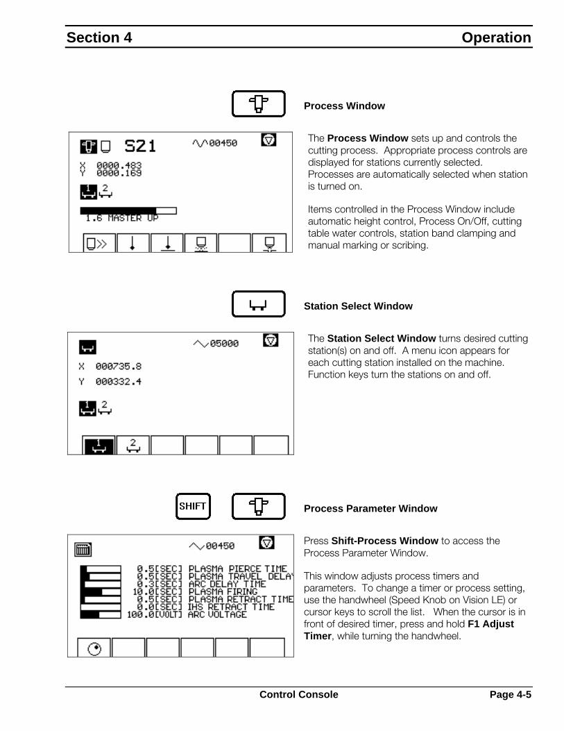
Process Window
The Process Window sets up and controls the cutting process. Appropriate process controls are displayed for stations currently selected. Processes are automatically selected when station is turned on.
Items controlled in the Process Window include automatic height control, Process On/Off, cutting table water controls, station band clamping and manual marking or scribing.
Station Select Window
The Station Select Window turns desired cutting station(s) on and off. A menu icon appears for each cutting station installed on the machine. Function keys turn the stations on and off.
Process Parameter Window
Press Shift-Process Window to access the Process Parameter Window.
This window adjusts process timers and parameters. To change a timer or process setting, use the handwheel (Speed Knob on Vision LE) or cursor keys to scroll the list. When the cursor is in front of desired timer, press and hold F1 Adjust Timer, while turning the handwheel.
Section 4 Operation
Control Console Page 4-5

4.2.3 Manual Controls
Manual controls provide operator control over program execution and machine motion.
Emergency Stop button is provided for emergency shut down of both process and machine motion.
Speed Potentiometer adjusts machine speed, or feed rate, during automatic cutting and manual motion.
Joystick manually moves machine in jog modes.
Directional Keypad manually moves machine in jog moves. Takes the place of a joystick on the LE model.
Rapid allows the operator to toggle in and out of rapid feedrate during manual jogging of machine.
The green Program Start button starts part program execution in automatic mode.
The red Program Stop button halts execution of a part program in automatic mode. Programmed motion is stopped, but cutting processes are not turned off.
Process Off stops the cutting or marking process. For processes equipped with automatic height control, a Master Up cycle is performed, raising motorized tool lifts. Use this button with Program Stop to manually stop a programmed cutting sequence.
Master Up raises all selected motorized station lifts for as long as button is pressed.
Piecemaker 2
Page 4-6 Control Console

4.3 Basic Operating Procedure
This basic operating procedure outlines the basic steps to cut production parts. Refer to subsequent sections for more detailed step descriptions.
Procedure
1. Power on machine.
See Page 4-9
2. Homing the machine.
See page 4-11
3. Download a program.
See Page 4-12
4. Jog to start point.
See Page 4-13
5. Select station
See Page 4-14
6. Start program execution.
See Page 4-15
7. Plasma operation.
See Page 4-18
8. Insulation cutting operation (if required).
See Page 4-24
Section 4 Operation
Basic Operating Procedure Page 4-7

4.4 Machine Power
4.4.1 Power On
Machine power on is a three-step process.
Step 1: Main Power Switch
The Main Power Switch is located on the electronics cabinet.
1 = Power ON
0 = Power OFF
Step 2: E-Stop Button
Once the main power switch is ON, the Emergency Stop button enables or disables power to the machine drive and cutting processes.
• Turn CLOCKWISE for power ON.
• PUSH for power OFF.
When powered up, the CNC performs a Power On Self-Test and displays the Data Input Window.
Step 3: Shift-Program Start
Push Shift-Program Start to turn on +24 volt power supply and enable the Vision Control outputs. Do this any time the E-Stop button is pressed or machine power is removed.
Piecemaker 2
Page 4-8 Machine Power

4.4.2 Power Off
To turn cutting machine power off :
1. Push Shift-Program Stop to switch off +24 volt power supply, disable drives and the CNC outputs. The CNC remains powered up, but machine gantry is powered down.
2. Leave CNC powered up, unless machine will be inactive for a long time. If so, turn main power switch to “0” to turn off all power to the Vision control.
3. Leave wall disconnect switch (or breaker) on unless performing machine maintenance.
Section 4 Operation
Machine Power Page 4-9

4.5 Homing the Machine
Each time the machine is powered up and before running any programs or moving the machine, the gantry must be “homed”. This requires sending the machine to the home position cams in each axis. This is where the CNC detects the home point, which sets the reference point for all machine movement. This allows the CNC to resume part cutting in case of power failure and enables the fixed points and software limit switches.
Press Motion Window.
The Motion Window appears. If the Motion Window is not at the main level, as shown, press Page until this screen appears.
Press F4 Reference Point Movement.
Adjust Speed Potentiometer to low speed. If machine speed is too fast during the homing procedure, machine will automatically E-Stop.
Crush hazard.
Machine starts automatically.
Before pressing Start, verify no personnel or equipment are in the machine’s way.
Machine will move by itself in both axes.
Press Start. Machine moves to the home position in each axis.
Piecemaker 2
Page 4-10 Homing the Machine

4.6 Downloading Programs
Production ductwork layouts are usually downloaded to the CNC using the UDL feature (Up/Down Load). UDL uses a serial data connection to transmit part program data from a host computer to the CNC.
Procedure
Select Data Input Window.
Press F1 to select Program Input-Output.
Press F1 again to select UDL.
Press F1 again to select Download.
A list box appears and shows program names available at the host computer. Use the Speed Knob or Joystick to scroll through list. Place cursor in front of desired program name.
Press F1 Confirm to select highlighted program.
Selected program is transmitted to the CNC. During transmission, block numbers are displayed to indicate transmission progress.
Press Page to cancel transmission.
Section 4 Operation
Downloading Programs Page 4-11

4.7 Moving the Machine
To position the cutting and marking tools and move the gantry bridge, use the Joystick on the CNC to manually jog machine in the longitudinal (rail) direction and transverse (beam) direction. Since the four main windows are active simultaneously, the Joystick can be used anytime the Motion Window is at the main level.
Procedure
Press Motion Window.
The Motion Window appears. If the screen is not at the main level, as shown, press Page until this screen appears.
Use the Joystick (or Keypad on LE) to move machine to desired cutting position.
Use the Speed Potentiometer and Rapid buttons to control machine speed.
Piecemaker 2
Page 4-12 Moving the Machine
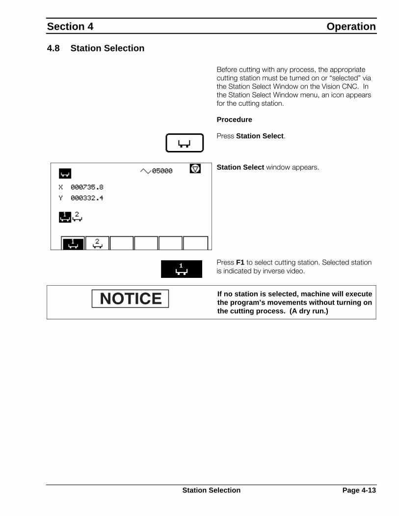
4.8 Station Selection
Before cutting with any process, the appropriate cutting station must be turned on or “selected” via the Station Select Window on the Vision CNC. In the Station Select Window menu, an icon appears for the cutting station.
Procedure
Press Station Select.
Station Select window appears.
Press F1 to select cutting station. Selected station is indicated by inverse video.
If no station is selected, machine will execute the program’s movements without turning on the cutting process. (A dry run.)
Section 4 Operation
Station Selection Page 4-13

4.9 Running Programs
All production part cutting is done by executing a part program. The part program contains cut path information as well as codes to turn the cutting process on and off at appropriate times. Programs may also contain feedrate information, kerf offset value and process setup data.
Procedure
Select Station Window to select cutting station.
Select Motion Window.
Press F1 to select Automatic Mode.
Press F2 to select a program from Memory.
The Motion Window, Automatic Mode, Program Selection screen appears. A selection box appears containing a list of all programs currently in memory.
Use Handwheel and cursor keys to scroll through program list.
Position cursor next to desired program.
Press F1 Confirm to select highlighted program.
Piecemaker 2
Page 4-14 Running Programs

The selected program is loaded and the Program Setup Screen is displayed.
Enter desired speed, kerf value and rotation values.
“Start at:” is normally set to 0001 and “Scale:” should be set to 1000.
When all parameters are set, press F1 Confirm. The Program Execution screen appears.
Press Program Start. Machine executes program.
During program execution, the graphics cursor displays the actual position of the cutting tool along the programmed path. The path is highlighted as it is cut, and the X- and Y-program coordinates are updated to show actual tool position. Kerf offset value (K) and current program block number (N) are also displayed. Actual feedrate is displayed at the top of screen.
Program Stop halts program motion but does not stop the cutting process.
Section 4 Operation
Running Programs Page 4-15

4.10 Timers and Process Parameters
Press Shift-Process Window to access timers and process parameters.
Parameter Window displays timers and process settings.
To change a timer or process setting, use the Speed Knob or cursor keys to scroll through list.
When cursor is in front of desired timer, press and hold F1 Adjust Timer.
To adjust parameter setting, turn Speed Knob while pressing F1.
Piecemaker 2
Page 4-16 Timers and Process Parameters

4.11 Plasma Operation
4.11.1 Introduction
Plasma arc cutting uses a high velocity plasma gas jet to cut through carbon steel, stainless steel and aluminum. This thermal cutting process severs metal by melting it then blowing the molten metal out of the way.
The plasma jet is formed by constricting a DC electric arc through an orifice using pressurized gas. Constricting the arc increases heat density, which speeds the melting process. Constricting the gas through the orifice, combined with the arc’s heating action creates a high velocity jet of ionized gas that blows away the molten material.
Modern plasma systems also utilize the oxidizing action of oxygen or air as the plasma gas to increase speed and improve edge quality on carbon steel.
1 Plasma torch
2 Plasma gas
3 Nozzle
4 Orifice
5 Plasma jet
6 Plate
7 Electrode
There are three steps to start a plasma arc cutting cycle: high frequency, pilot arc and main arc. Plasma gas is preflowed through the nozzle orifice. A relay that connects the copper nozzle to the ground (plate) is closed. A high frequency, high voltage signal is generated between the electrode and nozzle, which results in a low amperage, high frequency spark. This spark ionizes the plasma gas, creating a path for the pilot arc. The pilot arc is a low amperage DC arc that jumps from electrode to nozzle. The plasma gas then blows the pilot arc out of the orifice, where it contacts the workpiece, creating a path for the main arc. Once the main arc is established between the electrode and workpiece, the high frequency and pilot arc are switched off. This entire process takes place within a fraction of a second.
Section 4 Operation
Plasma Operation Page 4-17

4.11.2 Setup
Plasma system setup varies depending on plasma torch model, flow control and machine power supply. Refer to plasma system literature for proper setup of plasma cutting parameters.
Plasma system setup may require adjustment of:
Cut Gas
Select cut gas type, usually air or oxygen. Set pressure and/or flow rate.
Cutting Amperage
Set cutting amperage (AMPS) depending on material thickness and nozzle size.
Piecemaker 2
Page 4-18 Plasma Operation

4.11.3 Process Parameters
Press Shift-Process Window to access process parameters.
The Parameter Window appears. Below are applicable timer descriptions and how they effect the plasma cutting process.
Plasma Travel Delay
Sets the length of time the torch will stand still after the arc strikes. Set longer for thicker materials to allow time to pierce through material. For gauge materials, set timer to zero.
Plasma Preflow Time
Timer is factory set and should not be changed.
Plasma Postflow Time
Timer is factory set and should not be changed.
Arc Signal Time
Timer is factory set and should not be changed.
Section 4 Operation
Plasma Operation Page 4-19
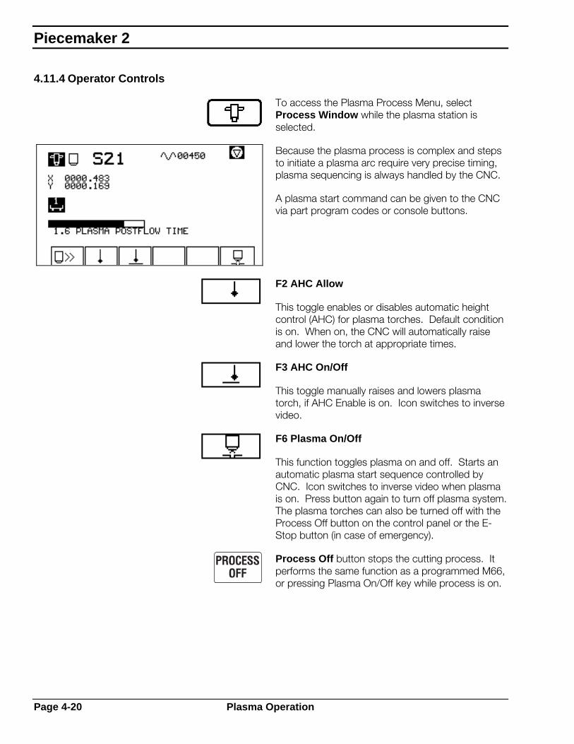
4.11.4 Operator Controls
To access the Plasma Process Menu, select Process Window while the plasma station is selected.
Because the plasma process is complex and steps to initiate a plasma arc require very precise timing, plasma sequencing is always handled by the CNC.
A plasma start command can be given to the CNC via part program codes or console buttons.
F2 AHC Allow
This toggle enables or disables automatic height control (AHC) for plasma torches. Default condition is on. When on, the CNC will automatically raise and lower the torch at appropriate times.
F3 AHC On/Off
This toggle manually raises and lowers plasma torch, if AHC Enable is on. Icon switches to inverse video.
F6 Plasma On/Off
This function toggles plasma on and off. Starts an automatic plasma start sequence controlled by CNC. Icon switches to inverse video when plasma is on. Press button again to turn off plasma system. The plasma torches can also be turned off with the Process Off button on the control panel or the E-Stop button (in case of emergency).
Process Off button stops the cutting process. It performs the same function as a programmed M66, or pressing Plasma On/Off key while process is on.
Piecemaker 2
Page 4-20 Plasma Operation

4.11.5 Automatic Operation
Automatic Plasma Cutting is done by starting a part program in Automatic Mode. Before starting program, check the following:
Station Selection. Select plasma station in Station Selection Window.
Process Settings. In the Process Parameter Window, set process timers and AHC parameters appropriately for material thickness and type.
When ready, press Program Start in Movement Window, Automatic Mode.
Section 4 Operation
Plasma Operation Page 4-21

4.11.6 Manual Operation
CNC must control the plasma cutting sequence. Manual operation of the plasma system simply requires pressing the Plasma On button. The CNC takes over control of plasma system sequencing. When the plasma arc is initiated, motion will be enabled.
Making a Manual Strip Cut
1. In Station Select Window select appropriate plasma station.
2. Use the Joystick (or Keypad on LE) to position torch at appropriate point over material.
3. Use Speed Potentiometer to set desired cutting speed.
4. Press Process Window.
5. Press AHC On/Off to turn on AHC. Torch will lower to the plate.
6. Press Plasma On/Off.
7. Press Movement Window.
8. Press and hold the Joystick (or Keypad on LE) in desired direction of travel. As soon as the arc strikes, the CNC will delay the appropriate length of time then will begin traveling in the selected direction.
9. Continue holding the Joystick (or Keypad on LE) in desired cut direction. If cutting scrap, jog torch off plate edge and arc will go out by itself.
10. When the end of the cut is reached, press Process Off to turn arc off.
Piecemaker 2
Page 4-22 Plasma Operation

Manually Starting Plasma In a Program
If a program has been halted or interrupted, you may need to manually restart the plasma. Take the following steps:
1. Use the Speed Potentiometer to set desired cutting speed.
2. Press Plasma On/Off. Torch will descend towards plate.
3. Before the arc starts, press Program Start. As soon as the arc strikes, the CNC will delay the appropriate length of time then begin traveling according to programmed movements
Section 4 Operation
Plasma Operation Page 4-23

4.12 Insulation Cutting Operation
4.12.1 Introduction
Waterjet cutting uses the power of water to cut through any material.
The 5hp pump provides pressurized water to the cutting head. The unique features of the cutting head stabilize the water before it enters the orifice, which shapes the water into a fine stream capable of extremely accurate cutting.
Water flow to the orifice is controlled by a needle valve, which is normally kept closed by a spring-loaded plunger. A solenoid valve controls the air pressure required to open the needle valve. When the solenoid valve opens, air pressure is introduced into the air chamber. The air pressure shifts the needle valve open, allowing water to flow through the orifice.
When the air pressure exhausts, the spring in the air cylinder extends the plunger, closing the needle valve and stopping water flow.
The waterjet cutting head is lightweight and versatile. It is rated for up to 5000 psi with a wide range of orifice and nozzle sizes. The orifices are premounted in a setscrew style retainer, which makes them easy to change with an Allen wrench.
1 Water inlet
2 Air chamber
3 Needle valve
4 Nozzle
5 Water inlet
6 Seat
7 Water chamber
8 Orifice
9 Water stream
Piecemaker 2
Page 4-24 Insulation Cutting Operation

4.12.2 Setup
Waterjet setup procedures may require adjustment to some or all of the following:
Pump
Check connecting hoses for water leaks – fix any leaks before proceeding with operation.
Air Pressure
Check air pressure supplied to machine. It should be 90 psi.
Section 4 Operation
Insulation Cutting Operation Page 4-25

4.12.3 Timers
The following timers are used in insulation waterjet cutting:
Pressure Delay Allows time for pump to reach full pressure. After the pump is turned on, sets the length of time the control will wait before supplying water to the cutting head.
Travel Delay After water is on, sets the length of time the control will delay travel to allow the water to pierce insulation completely before starting to move. The water drills a small hole deeper and deeper until the insulation is completely pierced. On thicker insulation this delay is longer. This timer must be set correctly. If not, the insulation will not get completely pierced and the part will not be completely cut out.
Piecemaker 2
Page 4-26 Insulation Cutting Operation

4.12.4 Operator Controls
Vision CNC allows fully automatic control of the cutting process and also provides manual controls for every part of the cutting cycle.
A waterjet start command can be given to the CNC via part program codes or console buttons.
To access the Waterjet Process Menu, select Process Window while a waterjet station is selected.
AHC Allow
This toggle enables or disables the automatic height control for the waterjet cutting head.
AHC On/Off
This toggle manually raises and lowers the waterjet cutting head if AHC Allow is on. Icon switches to inverse video.
Water On/Off
This icon toggles water on and off. Pressing this key will start an automatic waterjet start sequence controlled by the CNC. Icon switches to inverse video when waterjet cutting head is on. Press button again to turn waterjet process off. The waterjet cutting head can also be turned off with the Process Off button on the control panel or the E-Stop button (in case of emergency).
Section 4 Operation
Insulation Cutting Operation Page 4-27

4.12.5 Automatic Operation
Automatic waterjet cutting is done by starting a part program in Automatic Mode. However, before starting the program, check the following:
Cutting hazard.
Water pressure can severely damage hands and/or fingers during the cutting process.
The waterjet area must be clear of personnel, materials and equipment not involved in the process. Keep hands clear of waterjet cutting head during application.
Station Selection. Select appropriate cutting station in Station Select Window.
Process Settings. In the Process Parameter Window, set process timers appropriately for insulation thickness and type.
AHC On. Turn AHC on to drop waterjet cutting head. AHC Allow must be on.
Set Station Height. Manually raise or lower cutting station lift to desired height -usually 2-½" above the cutting surface – and lock in position with adjustable handles on back of station.
AHC Off. Press AHC again to raise waterjet cutting head.
Adjust Position. Use joystick (or Keypad on LE) to position torch at appropriate point over material.
Load Cutting Program. Selected program is loaded.
When ready, press Program Start in Movement Window, Automatic Mode.
Piecemaker 2
Page 4-28 Insulation Cutting Operation

4.12.6 Manual Operation
Manual operation of waterjet cutting process is possible for cutting scrap or testing purposes.
Procedure
This method uses functions in the Process Window to manually control water operation sequence.
Cutting hazard.
Water pressure can severely damage hands and/or fingers during the cutting process.
The waterjet area must be clear of personnel, materials and equipment not involved in the process. Keep hands clear of waterjet cutting head during application.
1. In Station Select Window select the waterjet station.
2. Manually raise or lower cutting station lift to desired height -usually 2-½" above the cutting surface – and lock in position with adjustable handles on back of station.
3. Use the Joystick (or Keypad on LE) to position torch at appropriate point over material.
4. Use Speed Potentiometer to set desired cutting speed.
5. Turn water pump on. Check for water leaks – fix any leaks before proceeding with operation.
6. Press Process Window.
7. Press AHC On/Off. Waterjet cutting head will lower to cutting position. Icon will turn dark for process on.
Section 4 Operation
Insulation Cutting Operation Page 4-29
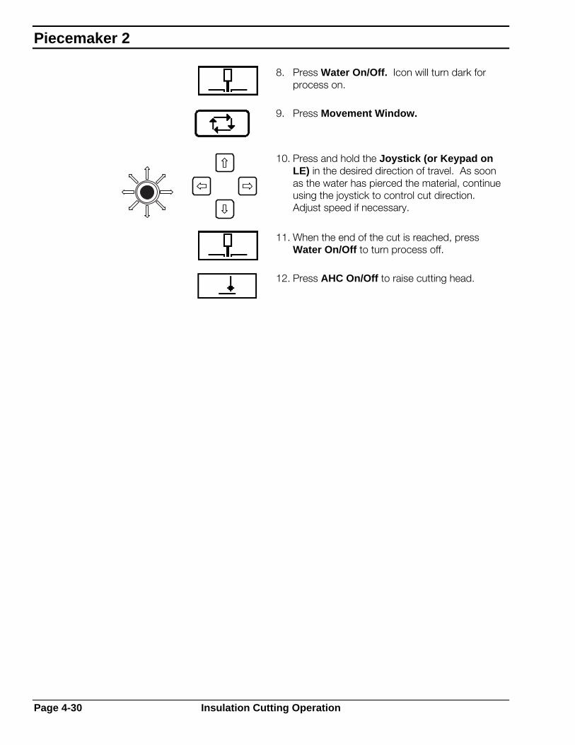
8. Press Water On/Off. Icon will turn dark for process on.
9. Press Movement Window.
10. Press and hold the Joystick (or Keypad on LE) in the desired direction of travel. As soon as the water has pierced the material, continue using the joystick to control cut direction. Adjust speed if necessary.
11. When the end of the cut is reached, press Water On/Off to turn process off.
12. Press AHC On/Off to raise cutting head.
Piecemaker 2
Page 4-30 Insulation Cutting Operation
Contents
5.1 Introduction.................................................................................... 1 5.2 Routine Maintenance..................................................................... 2
5.2.1 Introduction ........................................................................ 2 5.2.2 2 5.2.3 Frequency of Routine Maintenance................................... 3 5.2.4 3 5.2.5 Cleaning............................................................................. 4 5.2.6 Adjustment......................................................................... 5 5.2.7 Lubrication ......................................................................... 5
5.3 Preventive Maintenance Schedule ................................................ 6 5.4 Gantry Alignment Procedures........................................................ 9
5.4.1 Introduction ........................................................................ 9 5.4.2 Sequence of Alignment...................................................... 9 5.4.3 Rail Alignment.................................................................. 10 5.4.4 Side Guide Bearings........................................................ 11
5.5 Servo System Electrical Adjustments .......................................... 12 .5.1 Introduction ...................................................................... 12 5.5.2 Gain Adjustment .............................................................. 13 5.5.3 Balance Adjustment......................................................... 16 5.5.4 Response Adjustment...................................................... 17
5.6 Maintenance Procedures............................................................. 18 5.6.1 Drive Preload Tension – Planetary Gearbox ................... 19 5.6.2 Drive System Components – Small Planetary Gearboxes20 5.6.3 Y-Axis Carriage Wheels................................................... 22
5.7 Technical Descriptions................................................................. 24 5.7.1 Electronics Cabinet.......................................................... 25 5.7.2 Vision 1000/Vision LE Technical Description .................. 26 5.7.3 Drive Control System....................................................... 27 5.7.4 Budget Lift........................................................................ 29
Maintenance
Contents

PieceMaker 2

5.1 Introduction
The information in this chapter is provided to allow trained maintenance personnel to effectively maintain and repair the cutting machine. This manual covers subjects relating to the gantry including drives, vertical lifts and electronic subsystems. It is recommended that maintenance personnel read the control descriptions and operating instructions in this manual for a better understanding of machine operation. Before any maintenance is attempted, read and understand the Safety Section in the front of this manual.
Before an effort is made to repair the machine or numerical control, ensure the problem is not an operator error or a programming problem. Once these sources are eliminated, consider the machine itself. Mechanical components, such as gearboxes, motors, connections, switches and disk drives are subject to damage and wear. Only after these potential problem sources are proved trouble free, should attention turn to the solid-state electronics.
The Vision CNC is described in a separate manual supplied with the machine. Refer to ESAB manual "Operating Instructions for the Vision PC/NT Computer Numerical Controls" (Part # F14-133). Consult that manual for troubleshooting procedures regarding control and errors that appear on the CNC. This manual also contains information on using special diagnostic control capabilities that can isolate many machine problems.
Section 5 Maintenance
Introduction Page 5-1

5.2 Routine Maintenance
Introduction
Routine maintenance is generalized into three categories: cleaning, adjustment and lubrication. Routine maintenance procedures are an integral part of normal machine operation and will lengthen the life of various machine components.
The information in this chapter, combined with information contained in literature for specific equipment (torches, nozzles, etc.) provides instructions that ensure safe, efficient machine maintenance.
Pressurized fluid hazard.
Before starting any service or maintenance, turn equipment off and relieve all water pressure in lines.
Pressurized fluid streams can penetrate skin, causing severe personal injury. If any fluid is ejected against the skin, get medical attention immediately.
Piecemaker 2
Page 5-2 Routine Maintenance

5.2.1 Frequency of Routine Maintenance
Perform these procedures on a regular basis, depending on machine location and usage. Consider the following factors which may increase maintenance frequency:
• Machine is outdoors
• Machine is located near the ocean.
• Machine is exposed to high humidity.
• Machine is used continuously.
• Machine does not use a cutting table with downdraft fume exhaust.
• Machine is used above a dry cutting table, instead of a water table.
• Machine is used in a shop where other equipment produces dust and dirt.
If any of these factors applies to your installation, increase frequency of routine maintenance.
Section 5 Maintenance
Routine Maintenance Page 5-3

5.2.2 Cleaning
Because the cutting machine operates in a harsh environment, routine cleaning is one of the most important maintenance procedures. Dust and grit generated and distributed by plasma torch cutting accumulates on moving parts causing jamming and wear out. In addition, metallic dust that accumulates on electronic components can cause failures or serious damage. Listed below are the most important items to be cleaned:
Bearings
Any moving part on the cutting machine uses some type of bearing to provide smooth motion. Keep these bearings and the surface they roll on, clean and in some cases, lubricated. Clean bearings and bearing surfaces in the following locations:
• V-block wheels on the Y-axis carriage. Wipe with a clean cloth; use non-toxic, nonflammable solvent to remove hardened dirt deposits. Do not allow solvent to get inside bearings.
• Side guide bearings on the bottom of the main truck. Wipe with a clean cloth. Use non-toxic, nonflammable solvent to remove hardened dirt deposits. Do not allow solvent to get inside bearings.
Control Console
The control console exterior accumulates dust and dirt and should be kept clean so nothing gets inside the box or the button panels. Wipe CRT glass with a soft, damp cloth. Wipe dirt from the top and sides of the console weekly. Brush front panel off with a soft bristle brush or soft cloth. Do not use paper, which can scratch, or harsh chemicals, which can damage material.
Clean the floppy disk drive. The disk drive, while fairly well protected, may accumulate magnetic particles on the read/write head. Purchase a standard 3½" (89mm) floppy disk drive cleaning kit at most computer supply stores and use monthly.
The inside of the control console is well sealed and should not require cleaning.
Piecemaker 2
Page 5-4 Routine Maintenance

Electronics Cabinet
Electric shock hazard. Electric shock can cause severe injury or death.
Make sure power supply is OFF before starting any maintenance inside the electronics cabinet.
The electronics cabinet is well sealed but may accumulate grit inside. When cleaning inside the cabinet, vacuum dust and dirt from the bottom. Do not disturb any electrical connections.
5.2.3 Adjustment
The following items may require occasional adjustments to keep machine in top running order. Consult adjustment procedures in this chapter if there is a problem in any of these areas.
• Carriage V-blocks
• Side guide bearings
5.2.4 Lubrication
Very few cutting machine parts require regular lubrication. Most moving mechanical devices and bearings are sealed and do not require lubrication.
Waterjet Lift
The pneumatic slide on the waterjet cutting assembly requires a squirt of oil weekly. Use SAE 30 or equivalent.
Drive Gearbox
Gearboxes used on this machine are packed with grease and require no additional lubrication.
Bearings
All cutting machine bearings are sealed and should not be lubricated.
Section 5 Maintenance
Routine Maintenance Page 5-5

5.3 Preventive Maintenance Schedule
Time periods suggested below are based on average usage. If a machine is employed in a heavy usage cycle or is used outdoors, suggested time periods may be shortened. If usage is light, maintenance periods may be lengthened.
Pressurized fluid hazard.
Before starting any service or maintenance, turn equipment off and relieve all water pressure in lines. Close all hand valves before disassembling HP components.
Pressurized fluid streams can penetrate skin, causing severe personal injury. If any fluid is ejected against the skin, get medical attention immediately.
Daily
• Clean any slag accumulation from inside plasma torch shield/plate rider. Use a screwdriver or wire brush but avoid damaging plasma torch.
• Check plasma torch for wear and replace if necessary.
• Vacuum excess dirt and dust off machine; close all electronic cabinets to prevent dust entry.
• Wipe off main rails. There should not be any foreign objects that could interfere with wheels or pinion/drive rack.
Do not lubricate drive racks. Lubricants applied here accumulate dirt and promote problems.
• Wipe off beam guiding surfaces and ensure rack is clean and free from interference.
• Check powertrack for free movement. Cables must not be pinched or chaffed.
Piecemaker 2
Page 5-6 Preventive Maintenance Schedule

Pressurized fluid hazard.
Turn pump power OFF and relieve all pressure in lines before attempting any repairs. Do not repair any water leaks with pump ON. Use a piece of cardboard when checking for leaks – NEVER YOUR HAND.
Pressurized fluid streams can penetrate skin, causing severe personal injury. If any fluid is ejected against the skin, get medical attention immediately.
• Inspect all water hoses for leaks and damage. Replace if necessary.
• Inspect waterjet cutting head for leaks and wear. Replace if necessary.
Weekly
• Carefully inspect all hoses and hose connections for damage or looseness. Immediately replace those showing damage.
• Check plasma torch slide and waterjet pneumatic slide for smooth travel. Clean if necessary. Both slides require a squirt of SAE 30 motor oil, or equivalent.
• Inspect water seals and o-rings for leakage. Replace as necessary.
• Check rail scrapers for proper operation.
• Disengage Y-axis carriage and move by hand to make certain it travels freely.
• Use joystick and make certain machine and cross travel is smooth and steady.
• Check all filters in compressed air system. Remove any accumulated water in filter bowls.
• Check all control panel functions and lights.
Section 5 Maintenance
Preventive Maintenance Schedule Page 5-7

Monthly
• Check drive engage pivot for each drive assembly. Make sure it pivots freely in and out of rack. Check for play in the thrust bearings.
• Clean floppy disk reader using a standard 3½” (89mm) floppy disk cleaning kit.
• Inspect all electrical cable connectors and plugs. Make sure plugs are tight, cables are in good condition and do not bind or pull when moved. Replace any cables showing signs of wear.
• Inspect guide rollers on machine and carriage; readjust where necessary.
• Open electronics cabinet and carefully vacuum any dirt and dust accumulation. Do not blow out with compressed air.
• Check drive racks and replace or repair any badly worn sections.
• Inspect drive pinions on each axis drive. Replace any showing visible wear or teeth deformation.
Semiannually
• Drain cutting table. Refer to manual included with table for maintenance procedures.
Annually
• Repeat monthly procedures.
• Replace 3/8" hydraulic hose (5000psi) connecting pump to cutting head.
• Check straightness of main guide rail by stretching a piano wire along track with spacer blocks. Overall deviation from straightness should not exceed 0.005” (0.13mm) and should occur gradually (i.e., deviation in any 20 ft (7m) rail length should be substantially less).
Piecemaker 2
Page 5-8 Preventive Maintenance Schedule
5.4 Gantry Alignment Procedures
5.4.1 Introduction
This section covers mechanical and electrical alignment of this gantry shape cutting machine. These procedures may never be needed, or they may be used often, depending on machine installation, usage and maintenance. Only trained personnel with mechanical and electrical knowledge should use the following procedures. If trained personnel are not available, an ESAB Service Engineer should perform these procedures.
5.4.2 Sequence of Alignment
This gantry cutting machine is designed to provide accurate, smooth, repeatable, high-speed motion for the plasma cutting process. When problems occur with the machine’s performance, the first step is to eliminate the cutting process and analyze the gantry’s performance. If the problem is in the gantry’s performance, follow alignment procedures below. The alignment sequence is critical because each alignment procedure assumes that all previous alignments are correct.
1. Rail Alignment
2. Side Guide Bearings
3. Servo System Electrical Adjustments
Section 5 Maintenance
Gantry Alignment Procedures Page 5-9
5.4.3 Rail Alignment
Machine rails are the reference point for all machine movement and must be properly aligned before addressing other machine portions. Rails must be straight, level, parallel and the correct gauge (distance between rails). Improperly installed rails can move or "walk" during operation and lose alignment. If there is any reason to believe the rails are distorted in any plane mentioned above, perform the following rail alignment procedure.
Severe rail misalignment can cause a number of easily misinterpreted symptoms. The X-rail (on left-hand side) is the most critical rail member and its straightness is the most critical factor. If this rail is not straight, the machine can be forced out of square to follow it. The drives fight this misalignment while running and will, in the most serious cases, cause one or more of the following symptoms:
• Excessive "DEVIATION ERRORS" in X-axis.
• "EXCESS CURRENT" faults on PWM Drive boards.
• X-axis performance problems.
• Rough drives in X-direction.
If the machine exhibits these symptoms, if rails have been bumped or jarred in any way or machine is relocated, you must realign rails per the instructions in the Installation Section.
Piecemaker 2
Page 5-10 Gantry Alignment Procedures

5.4.4 Side Guide Bearings
Side guide bearings keep the machine trucks positioned correctly on the rails. Confirm their correct adjustment before proceeding with alignment. Check front and rear of side guide bearings for minimum clearance. Adjust so they are touching rails on both sides but can still be hand-turned on one side. If the above is not true, follow alignment procedure below.
To adjust side guide bearings:
1. Disengage drives.
2. Push machine down rails (repeatedly if necessary) until both outboard bearings are in contact with the side of the rail.
3. Loosen shoulder bolt with box-end wrench.
4. Turn eccentric bushing with open-end wrench. Adjust bearing until it begins to contact side of rail.
5. While holding bushing with one wrench, tighten shoulder bolt with the other.
You should be able to turn bearing by hand but feel it rub against side of rail.
1 Truck
2 Bearing
3 Eccentric bushing
4 Shoulder bolt
5 Guide rail
6 Fixed bearing
Section 5 Maintenance
Gantry Alignment Procedures Page 5-11

5.5 Servo System Electrical Adjustments
5.5.1 Introduction
This procedure only applies to machines with PWM Drive Amplifiers shown below.
There are four potentiometer adjustments on the motor drive unit. These adjustments are preset at the factory and should not require field adjustment. However, if a motor drive unit is replaced or the performance needs to be modified, these pots function as follows:
P1 Loop gain CW increases gain
P2 Current limit CW increases current limit
P3 Reference gain CW increases gain
P4 Offset adjust N/A
Presets
Four DIP switches on the motor drive unit set the amplifier’s operating mode. Set all four switches to OFF position.
Set Current Limit potentiometer, P2, fully clockwise.
Check gain and balance adjustments for each axis. The gain adjustment affects the motor speed for a given drive signal. The balance adjustment affects the motor drift when there is no drive signal. Both adjustments can be made without any measuring devices and both use the CNC to provide speed feedback from the motors.
Piecemaker 2
Page 5-12 Servo System Electrical Adjustments

5.5.2 Gain Adjustment
Use the Speed Measurement display of Vision CNC to adjust gain of PWM amplifiers. This feature momentarily drives the motors and displays the resulting maximum drive speed. Adjust each axis to have the same maximum drive speed.
Crush hazard.
Machine starts automatically.
1. Before doing Speed Measurement Test, verify no personnel or equipment are in machine’s way.
2. Machine will move by itself in both axes.
Procedure
Leave drives engaged.
Press Shift-Data Window to select Startup Window.
Startup Window appears.
If Startup Window menu does not display all options shown here, press Shift-Rapid to access Service Mode.
A message indicates Service Mode is activated. Press F1 to clear message.
Section 5 Maintenance
Servo System Electrical Adjustments Page 5-13

In Startup Window, press F2 to select Speed Measurement Test.
Speed Measurement screen appears.
To start Speed Measurement, press F1 to select X-axis or F2 to select Y-axis.
During speed measurement, the function key for the selected axis is displayed in inverse video. When machine stops, it returns to normal.
The selected axis moves about 1" (25mm) in the positive direction, and then moves back about 1" (25mm) in the negative direction. Display shows calculated drive speed.
Piecemaker 2
Page 5-14 Servo System Electrical Adjustments

At this time, make adjustments to Speed Potentiometer, P3, on PWM drive board. Repeat test and check speed display. Continue making adjustments and repeat test until a speed of 400ipm (10160 mm/min) is displayed.
When each drive is adjusted satisfactorily, press Backpage to exit Speed Measurement display. New speed values are recorded in Machine Constants.
Section 5 Maintenance
Servo System Electrical Adjustments Page 5-15

5.5.3 Balance Adjustment
To adjust balance of PWM amplifiers, disconnect the drive signal outputs and use the Loop Error Display feature of the CNC. This display shows the position following the error of each axis. When an amplifier’s balance is out of adjustment, the loop error value climbs.
Procedure
Manually release the tension spring to disengage the drive pinions from drive rack. Use a block of wood to block out drives. Disengage drives, but watch carefully in case they drift.
Open the CNC console. Disconnect the X8 connector from the Process I/O Board (PIO). This disconnects the CNC’s drive signal output. The PWM drive amplifiers should hold the motors still. Since actual motor output shaft cannot be seen, use the Loop Error Display to see if motors are drifting.
Press Shift-F1 to access Loop Error Display.
The loop error (position following distance) is displayed for each axis.
Piecemaker 2
Page 5-16 Servo System Electrical Adjustments
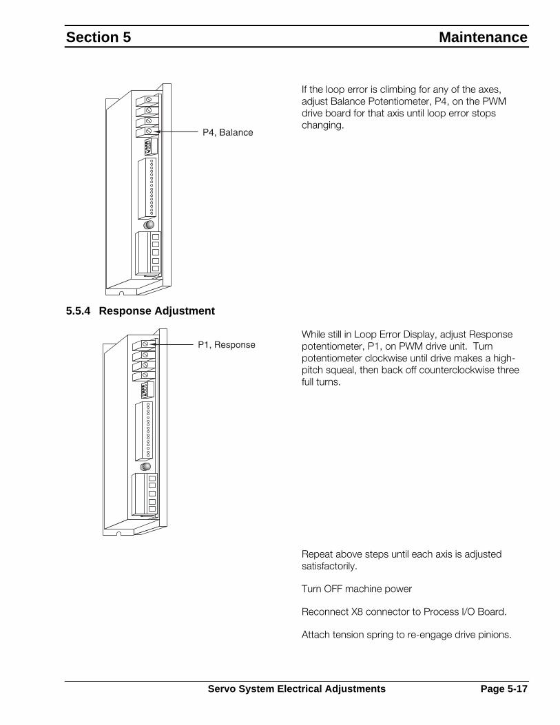
If the loop error is climbing for any of the axes, adjust Balance Potentiometer, P4, on the PWM drive board for that axis until loop error stops changing.
5.5.4 Response Adjustment
While still in Loop Error Display, adjust Response potentiometer, P1, on PWM drive unit. Turn potentiometer clockwise until drive makes a high- pitch squeal, then back off counterclockwise three full turns.
Repeat above steps until each axis is adjusted satisfactorily.
Turn OFF machine power
Reconnect X8 connector to Process I/O Board.
Attach tension spring to re-engage drive pinions.
Section 5 Maintenance
Servo System Electrical Adjustments Page 5-17

5.6 Maintenance Procedures
The following section contains maintenance procedures for many of the systems and devices used on ESAB cutting machines. Only qualified maintenance personnel should use these procedures.
Piecemaker 2
Page 5-18 Maintenance Procedures

5.6.1 Drive Preload Tension – Planetary Gearbox
An adjustable tension spring holds each drive pinion tightly against the drive racks. The spring is adjusted at the factory and normally requires little adjustment after installation. After long periods of use, the spring tension may require adjustment. Use the following guidelines to adjust the preload tension spring:
1. Completely loosen spring tension by loosening the lock nut, then turning the adjusting bolt counterclockwise.
2. Turn adjusting bolt clockwise until spring pushes slightly against the drive.
3. Turn adjusting bolt clockwise an additional 4.5 turns.
4. Tighten lock nut against bracket.
5. Check for proper engagement and disengagement by actuating the disengage air switch.
1 Pivot point
2 Adjusting bolt
3 Lock nut
4 Tension spring
5 Drive mount
6 Servo drive assembly
Setting preload tension too high causes excessive wear on the rack and pinion. Setting tension too low allows pinion to pop out and skip teeth while machine is running.
Section 5 Maintenance
Maintenance Procedures Page 5-19

5.6.2 Drive System Components – Small Planetary Gearboxes
Drive Motor
The servo drive assembly consists of the following replaceable components: motor, gearbox, encoder and output pinion in one assembly.
The drive motor may need replaced during the life of the machine. To replace:
1. Turn off and lock out all machine power.
2. Remove motor cable and encoder cable from input box at top of motor.
3. Use a 3mm (1/8") Allen wrench to remove the four cap screws mounting the motor to the gearbox.
4. Remove the threaded plug from the pinion bolt access hole on the gearbox.
5. Rotate the output pinion until the head of the input pinion bolt is aligned with the pinion access hole.
6. Insert the Allen wrench through the pinion access hole into the head of the pinion bolt and loosen the bolt.
7. Carefully remove motor by lifting it straight up from the gearbox. Do not twist or tilt motor.
1 Motor with encoder
2 Cap screws and lock washers
3 Motor shaft
4 Threaded plug
5 Pinion bolt access hole
6 Gearbox
7 shaft key
8 Gearbox shaft
9 Setscrews
10 Drive pinion
8. Make sure motor shaft is clean and dry. Insert the motor shaft into the gearbox pinion. Align the motor flange mounting holes with the mounting holes on the gearbox.
9. Mount the gearbox to the motor using the four cap screws and lock washers supplied.
10. Carefully tighten the pinion bolt to the torque specified by the gearbox manufacturer.
11. Reinsert and tighten the threaded plug in the pinion bolt access hole.
Piecemaker 2
Page 5-20 Maintenance Procedures

Drive Pinions
Drive pinions eventually need replacement. To change X- and Y-axis drive pinions:
1. Turn off and lock out all machine power.
2. Pull out drive assembly to disengage pinion from the rack.
3. Loosen the two setscrews that hold the pinion on the gearbox output shaft.
4. Use a gear puller to slide pinion off the shaft.
5. Clean shaft with solvent and emery cloth, if necessary.
6. Install new pinion on shaft, making sure pinion lines up with rack at proper height on shaft. Ensure key is installed properly.
7. Tighten setscrews and make sure pinion is properly engaged.
8. Adjust pinion so there is ¼" (6.4mm) gap between the pinion bottom and the shaft end.
Lubrication
Gearboxes used on this machine are packed with grease and a continuous lubricant redistribution ensures low wear over the lifetime of the gearbox. No additional lubrication is required.
Section 5 Maintenance
Maintenance Procedures Page 5-21

5.6.3 Y-Axis Carriage Wheels
The Y-axis carriage uses four V-wheels to provide smooth linear motion along the dual-V-track of the crossbeam.
Adjustment
The top two wheels on the Y-axis carriage are fixed, the bottom two are adjustable.
To adjust V-wheels:
1. Use socket wrench or box end wrench to loosen the wheel mounting bolt.
2. Insert a narrow open-end wrench over the hexed portion of the adjustable bushing, between lower V-wheel and the carriage plate.
3. Turn bushing to adjust bearing up or down as necessary.
4. While holding the bushing in place, tighten mounting bolt.
5. The bearing should be slightly preloaded against the rail so the carriage moves freely across the rail but there is no play in carriage.
1 Stationary wheels
2 Adjustable wheels
Piecemaker 2
Page 5-22 Maintenance Procedures

Replacement
A bolt holds each V-wheel in place. The upper wheels use a spacer; the lower wheels use an eccentric bushing. To replace V-wheels:
1. Remove all accessories from carriage front and top.
2. Remove the mounting bolt in order to remove the lower bearings.
3. Remove carriage from the beam and service bearings as necessary.
1 Y-axis carriage
2 Screw
3 V-wheel
4 Bearing
5 Spacer
6 Eccentric spacer
Section 5 Maintenance
Maintenance Procedures Page 5-23

5.7 Technical Descriptions
The following section contains technical descriptions of many systems used on ESAB cutting machines. These technical descriptions are intended to give sufficient understanding of the systems operation for maintenance personnel to troubleshoot and maintain these systems.
Piecemaker 2
Page 5-24 Technical Descriptions

5.7.1 Electronics Cabinet
The Electronics Cabinet is rail stand mounted on the side of the machine. It contains many electronic subsystems, including drives, station control electronics and power distribution circuits.
MB01
KO316
KOA14
SVO1 BOARD
SVO3 BOARDSVO1 BOARD
SVO1 BOARDSVO1 BOARDSVO1 BOARD
EST
OP
XFMER
511
APA
P_0
APA
P_1
TB1
APA
P_7
APA
P_5
APA
P_6
APA
P_4
APA
P_2
APA
P_3
GE
MCRA40E40E
MCRA
GE
PWRCNC
BR2
BR1
TB3
DR
AM
P'X
'
11658
15
DA
R Y
DA
R X
1
2814
DR
AM
P'Y
'
C3
C424V60V
C2
C1
24VC6
C5
1
TB2
5
20V
K1
CO
RC
OMFI
LTER
EMI
EMI FILTER
FU6FU5FU7
FU3FU2FU1
FU4
1
3
2
654 7 8
11
9
10
1. Triac Output Board
2. Analog Output Board
3. Mainboard/ LCASIOB
4. Rectifier, 60VAC
5. Rectifier, 24VAC
6. Miniture Relays
7. Main Transformer
8. Capacitors
9. Fuses
10. Line Filter
11. PWM Servo Amplifiers
The center panel of the electronics cabinet mounts the main terminal strip (TB1), TB3, transformer, filter capacitors, 24V and 60V rectifiers, relays, and PWM servo drive amplifiers.
The secondary voltage from the servo transformer is rectified by the 60V rectifier, then filtered by the 60V filter capacitor. The 60VDC supplies the PWM servo amplifiers for the drive motors.
The 24-Volt DC power supply comes from a set of secondary taps from the servo transformer. AC voltage is rectified and filtered to create two separate 24VDC supplies. 24VDC is supplied to the I/O system and station lift motors.
The left-hand side panel of the electronics cabinet mounts the centralized I/O system (LCASIOB), analog board and Triac output board.
The I/O mainboard is connected to the CNC by the serial I/O bus (ASIOB). It then controls the attached I/O components, including but not limited to: analog output boards, relay output boards, and Triac output boards.
The right-hand side panel of the electronics cabinet mounts the fuses, AC line filter and TB2.
Section 5 Maintenance
Technical Descriptions Page 5-25

5.7.2 Vision 1000/Vision LE Technical Description
Process I/OBoard (PIO)
ISA Buss
BIOS
CPU
RAM
P Amp
Y Amp
X Amp
X4 X2 X1
X8
Not used on Vision LE
ServoSignalOutput
E P
XY
EE
OperatorControlPanel
LCDDisplay
I/OSystem
F04000
Power Supply
Disk Drive
Disk Drive
115 VAC
Optional on the Vision LE
Digital I/O Board (DIO)
X21 X20DirectInputs Outputs
The Vision Computer Numerical Control is a PC based cutting machine controller. A PC motherboard provides processor, RAM and bus components. Drive control and I/O are handled by two additional boards - Process I/O board (PIO) and Digital I/O board (DIO).
The PIO Board controls the servo drive system providing analog outputs, drive enable outputs and encoder inputs for each axis.
The DIO Board handles direct inputs and outputs, interface with both the operator panel and the I/O system. The I/O interface is a Serial Bus that can interface to either remote I/O boards or a serial to parallel interface boards. The Digital I/O board also supplies the digital display data signal, which is interpreted and displayed by the LCD device.
A standard floppy disk drive controller is built into the motherboard and interfaces with the two disk drives (one is standard, 2 optional on Vision LE).
Piecemaker 2
Page 5-26 Technical Descriptions
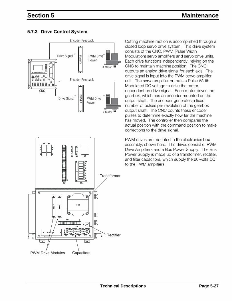
5.7.3 Drive Control System
Cutting machine motion is accomplished through a closed loop servo drive system. This drive system consists of the CNC, PWM (Pulse Width Modulation) servo amplifiers and servo drive units. Each drive functions independently, relying on the CNC to maintain machine position. The CNC outputs an analog drive signal for each axis. The drive signal is input into the PWM servo amplifier unit. The servo amplifier outputs a Pulse Width Modulated DC voltage to drive the motor, dependent on drive signal. Each motor drives the gearbox, which has an encoder mounted on the output shaft. The encoder generates a fixed number of pulses per revolution of the gearbox output shaft. The CNC counts these encoder pulses to determine exactly how far the machine has moved. The controller then compares the actual position with the command position to make corrections to the drive signal.
PWM drives are mounted in the electronics box assembly, shown here. The drives consist of PWM Drive Amplifiers and a Bus Power Supply. The Bus Power Supply is made up of a transformer, rectifier, and filter capacitors, which supply the 60-volts DC to the PWM amplifiers.
Section 5 Maintenance
Technical Descriptions Page 5-27
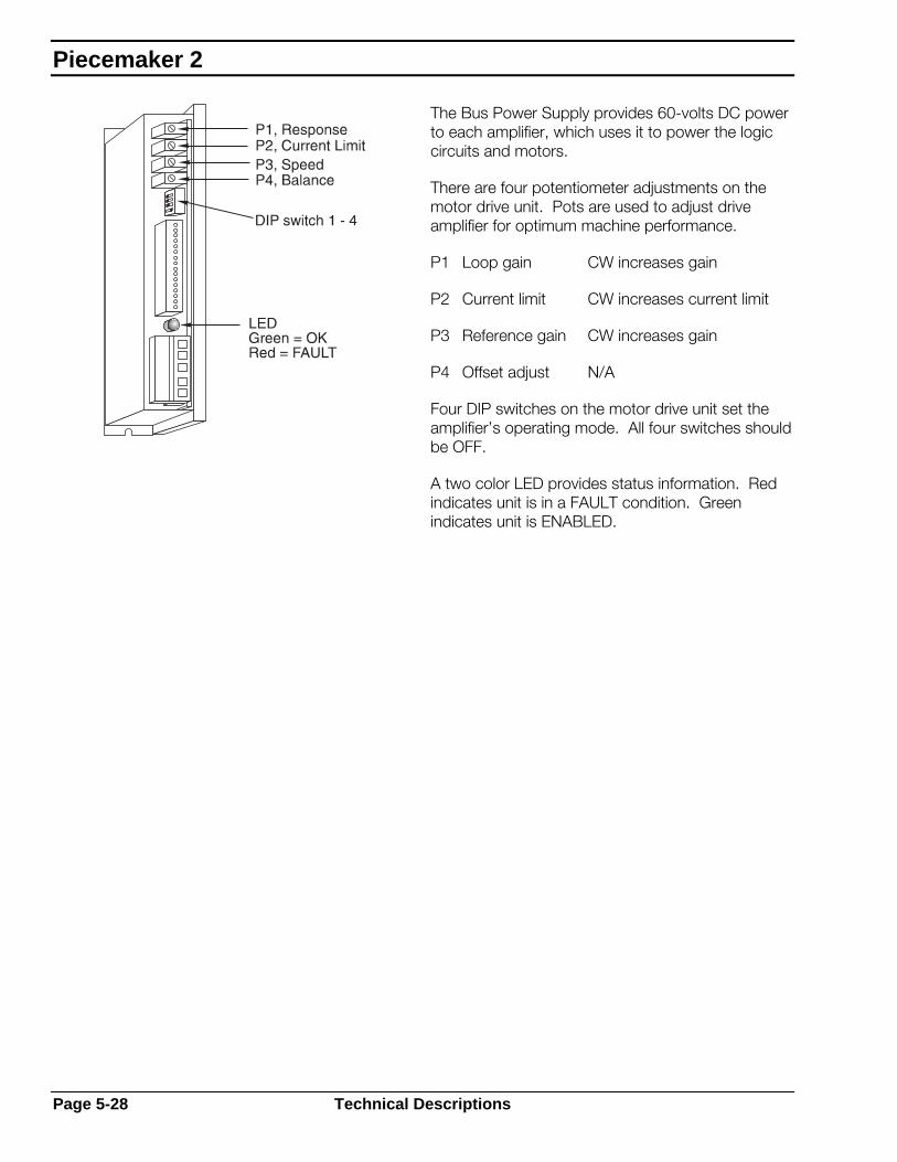
The Bus Power Supply provides 60-volts DC power to each amplifier, which uses it to power the logic circuits and motors.
There are four potentiometer adjustments on the motor drive unit. Pots are used to adjust drive amplifier for optimum machine performance.
P1 Loop gain CW increases gain
P2 Current limit CW increases current limit
P3 Reference gain CW increases gain
P4 Offset adjust N/A
Four DIP switches on the motor drive unit set the amplifier’s operating mode. All four switches should be OFF.
A two color LED provides status information. Red indicates unit is in a FAULT condition. Green indicates unit is ENABLED.
Piecemaker 2
Page 5-28 Technical Descriptions
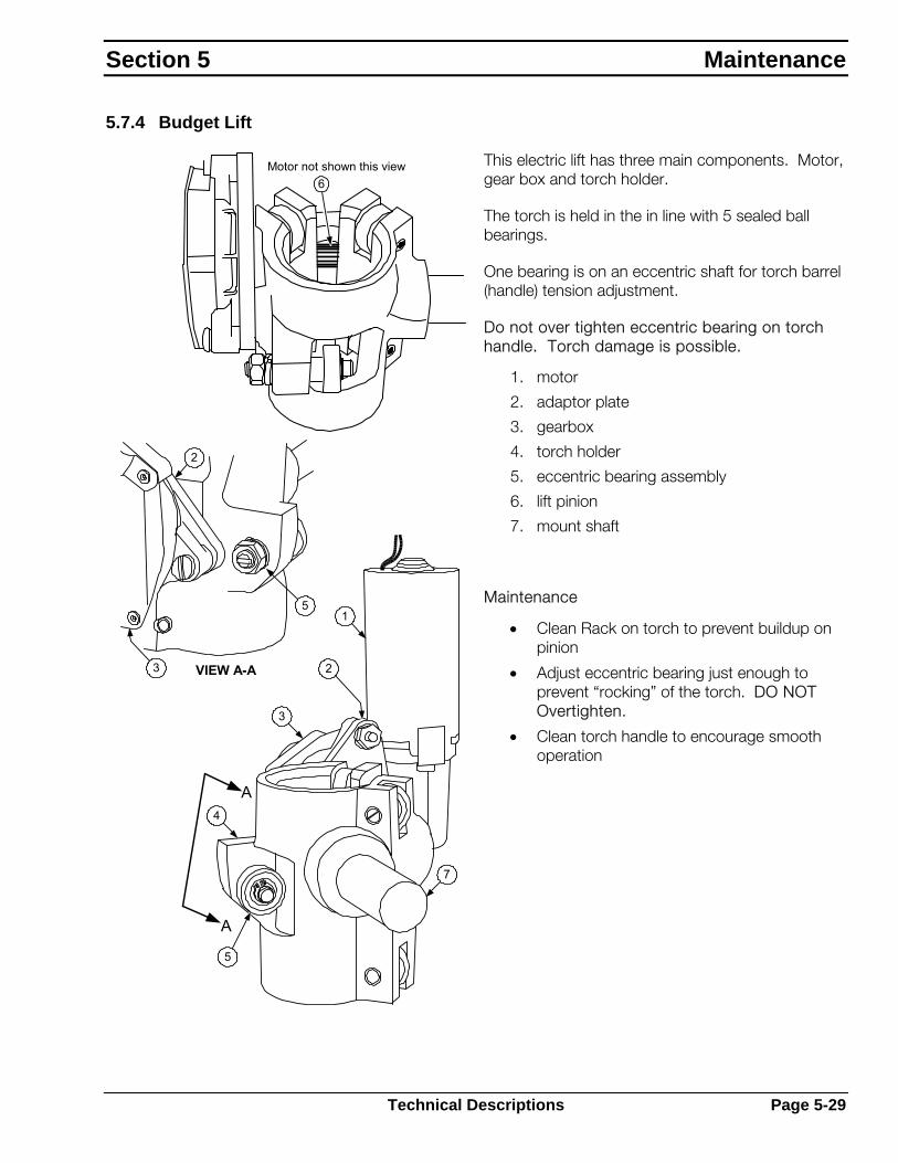
5.7.4 Budget Lift
This electric lift has three main components. Motor, gear box and torch holder.
The torch is held in the in line with 5 sealed ball bearings.
One bearing is on an eccentric shaft for torch barrel (handle) tension adjustment.
Do not over tighten eccentric bearing on torch handle. Torch damage is possible.
1. motor
2. adaptor plate
3. gearbox
4. torch holder
5. eccentric bearing assembly
6. lift pinion
7. mount shaft
VIEW A-A
6Motor not shown this view
1
3
4
5
2
7
A
A
5
2
3
Maintenance
• Clean Rack on torch to prevent buildup on pinion
• Adjust eccentric bearing just enough to prevent “rocking” of the torch. DO NOT Overtighten.
• Clean torch handle to encourage smooth operation
Section 5 Maintenance
Technical Descriptions Page 5-29

This page intentionally left blank.
Piecemaker 2
Page 5-30 Technical Descriptions
Replacement Parts
Contents
Contents
6.1 General Information ...........................................................................6-1
6.2 Ordering Information..........................................................................6-1
6.3 16' x 5' Wide Basic Piecemaker Plus.................................................6-2
6.4 16' x 6' Wide Basic Piecemaker Plus.................................................6-5
6.5 25' x 5' Wide Basic Piecemaker Plus.................................................6-8
6.6 32' x 6' Wide Basic Piecemaker Plus...............................................6-11
6.7 Torch Lifter Assembly ......................................................................6-14
6.8 Carriage, Servo Drive.......................................................................6-17
6.9 Electronics Cabinet..........................................................................6-19
6.10 Waterjet Cutting Head Assembly ...................................................6-22
6.11 Waterjet Addition Assembly ...........................................................6-25
6.12 Servo Drive Assembly with Planetary Gearbox...............................6-28
6.13 Soft Touch OMNI Interface Box .....................................................6-29
6.14 Plate Rider, Plasma .......................................................................6-31
6.15 Torch Holder .................................................................................6-32
6.16 Main Truck Assembly ....................................................................6-33
6.17 Y Axis Carriage Assembly..............................................................6-35
6.18 Torch Lifter Assembly ....................................................................6-37
6.19 Electronics Cabinet Assembly........................................................6-40
6.20 E-Stop Box Assembly....................................................................6-43
6.21 Lite Touch with Collision ................................................................6-44
6.22 Lite Touch .....................................................................................6-46
6.23 Rail, 16' x 5' Wide .........................................................................6-47
6.24 Rail, 25' x 5' Wide .........................................................................6-49
6.25 Rail, 16' x 6' Wide .........................................................................6-51
6.26 Rail, 32' x 6' Wide .........................................................................6-53
6.27 Encoder Cable Assembly (Planetary Drives) ...................................6-55
6.28Vision LE Control ............................................................................6-57
6.29 Vision 1000 Control Console .........................................................6-58
6.30 Vision 1000 Control Electronics .....................................................6-59

Piecemaker 2

6.1 General Information
This section provides replacement part information and will assist during machine maintenance. It is arranged by functional groups or assemblies for easy identification of individual parts and replaceable assemblies.
The Replacement Parts List consists of a parts list for the main assembly and one for each major assembly and subassembly. Item numbers that identify parts in the illustration are given in the list, where applicable, along with part numbers and descriptive information.
The four column parts list for each figure is arranged to show the assembly relationship of parts and subassemblies. Information given in each of these columns is as follows:
Column 1, ITEM: Lists each index number found on the illustration. When no index number is given for a part or assembly, it is not illustrated separately in the illustration, but its part name and description provide identification. When ordering, use the correct part number for the option used on your machine.
Column 2, PART #: Gives the ESAB part number of the part or assembly to which the index number has been assigned. Common hardware items or other parts readily available from commercial sources are not included. Parts purchased by ESAB from vendors are listed by ESAB part numbers. Hardware is specified as items in the parts lists but normally doesn’t have an ESAB part number.
Column 3, QUANTITY: Indicates the part quantity used in that assembly. Do not use this number as a recommended quantity of spare parts. The customer must determine how many spare parts to purchase.
Column 4, DESCRIPTION: Names the part or assembly and includes other identifying information.
6.2 Ordering Information
When ordering replacement parts, order by part number and complete part description as given in the description column. Also, give machine model and serial number. Address all inquiries to your local ESAB Distributor or to ESAB Cutting Systems, P.O. Box 100545, Florence, South Carolina, 29501.
This manual may contain part illustrations not applicable to your specific machine. To avoid unnecessary delays, positively identify your correct assembly before ordering replacement parts.
Replacement Parts
General Information Page 6-1
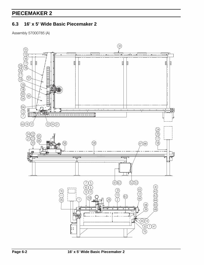
6.3 16' x 5' Wide Basic Piecemaker 2
Assembly 57000785 (A)
PIECEMAKER 2
Page 6-2 16' x 5' Wide Basic Piecemaker 2
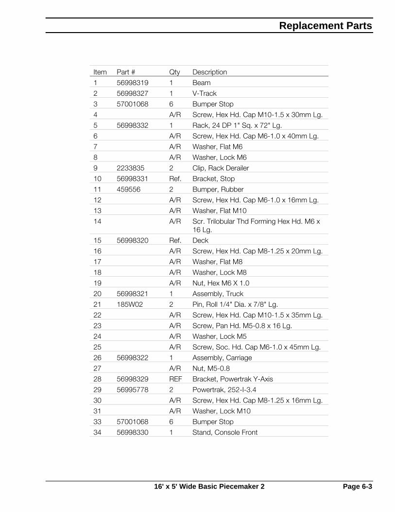
Item Part # Qty Description
1 56998319 1 Beam
2 56998327 1 V-Track
3 57001068 6 Bumper Stop
4 A/R Screw, Hex Hd. Cap M10-1.5 x 30mm Lg.
5 56998332 1 Rack, 24 DP 1" Sq. x 72" Lg.
6 A/R Screw, Hex Hd. Cap M6-1.0 x 40mm Lg.
7 A/R Washer, Flat M6
8 A/R Washer, Lock M6
9 2233835 2 Clip, Rack Derailer
10 56998331 Ref. Bracket, Stop
11 459556 2 Bumper, Rubber
12 A/R Screw, Hex Hd. Cap M6-1.0 x 16mm Lg.
13 A/R Washer, Flat M10
14 A/R Scr. Trilobular Thd Forming Hex Hd. M6 x 16 Lg.
15 56998320 Ref. Deck
16 A/R Screw, Hex Hd. Cap M8-1.25 x 20mm Lg.
17 A/R Washer, Flat M8
18 A/R Washer, Lock M8
19 A/R Nut, Hex M6 X 1.0
20 56998321 1 Assembly, Truck
21 185W02 2 Pin, Roll 1/4" Dia. x 7/8" Lg.
22 A/R Screw, Hex Hd. Cap M10-1.5 x 35mm Lg.
23 A/R Screw, Pan Hd. M5-0.8 x 16 Lg.
24 A/R Washer, Lock M5
25 A/R Screw, Soc. Hd. Cap M6-1.0 x 45mm Lg.
26 56998322 1 Assembly, Carriage
27 A/R Nut, M5-0.8
28 56998329 REF Bracket, Powertrak Y-Axis
29 56995778 2 Powertrak, 252-I-3.4
30 A/R Screw, Hex Hd. Cap M8-1.25 x 16mm Lg.
31 A/R Washer, Lock M10
33 57001068 6 Bumper Stop
34 56998330 1 Stand, Console Front
Replacement Parts
16' x 5' Wide Basic Piecemaker 2 Page 6-3
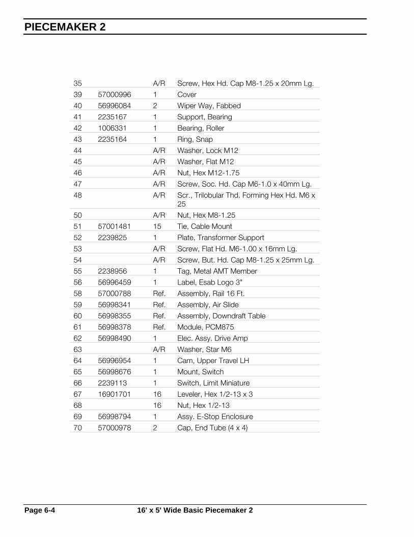
35 A/R Screw, Hex Hd. Cap M8-1.25 x 20mm Lg.
39 57000996 1 Cover
40 56996084 2 Wiper Way, Fabbed
41 2235167 1 Support, Bearing
42 1006331 1 Bearing, Roller
43 2235164 1 Ring, Snap
44 A/R Washer, Lock M12
45 A/R Washer, Flat M12
46 A/R Nut, Hex M12-1.75
47 A/R Screw, Soc. Hd. Cap M6-1.0 x 40mm Lg.
48 A/R Scr., Trilobular Thd. Forming Hex Hd. M6 x 25
50 A/R Nut, Hex M8-1.25
51 57001481 15 Tie, Cable Mount
52 2239825 1 Plate, Transformer Support
53 A/R Screw, Flat Hd. M6-1.00 x 16mm Lg.
54 A/R Screw, But. Hd. Cap M8-1.25 x 25mm Lg.
55 2238956 1 Tag, Metal AMT Member
56 56996459 1 Label, Esab Logo 3"
58 57000788 Ref. Assembly, Rail 16 Ft.
59 56998341 Ref. Assembly, Air Slide
60 56998355 Ref. Assembly, Downdraft Table
61 56998378 Ref. Module, PCM875
62 56998490 1 Elec. Assy. Drive Amp
63 A/R Washer, Star M6
64 56996954 1 Cam, Upper Travel LH
65 56998676 1 Mount, Switch
66 2239113 1 Switch, Limit Miniature
67 16901701 16 Leveler, Hex 1/2-13 x 3
68 16 Nut, Hex 1/2-13
69 56998794 1 Assy. E-Stop Enclosure
70 57000978 2 Cap, End Tube (4 x 4)
PIECEMAKER 2
Page 6-4 16' x 5' Wide Basic Piecemaker 2

6.4 16' x 6' Wide Basic Piecemaker 2
Assembly 57000786 - LF (A) and 57000798 – RR (OR)
Replacement Parts
16' x 6' Wide Basic Piecemaker 2 Page 6-5
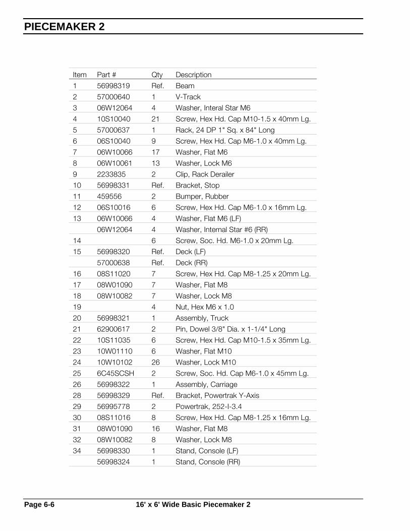
Item Part # Qty Description
1 56998319 Ref. Beam
2 57000640 1 V-Track
3 06W12064 4 Washer, Interal Star M6
4 10S10040 21 Screw, Hex Hd. Cap M10-1.5 x 40mm Lg.
5 57000637 1 Rack, 24 DP 1" Sq. x 84" Long
6 06S10040 9 Screw, Hex Hd. Cap M6-1.0 x 40mm Lg.
7 06W10066 17 Washer, Flat M6
8 06W10061 13 Washer, Lock M6
9 2233835 2 Clip, Rack Derailer
10 56998331 Ref. Bracket, Stop
11 459556 2 Bumper, Rubber
12 06S10016 6 Screw, Hex Hd. Cap M6-1.0 x 16mm Lg.
13 06W10066 4 Washer, Flat M6 (LF)
06W12064 4 Washer, Internal Star #6 (RR)
14 6 Screw, Soc. Hd. M6-1.0 x 20mm Lg.
15 56998320 Ref. Deck (LF)
57000638 Ref. Deck (RR)
16 08S11020 7 Screw, Hex Hd. Cap M8-1.25 x 20mm Lg.
17 08W01090 7 Washer, Flat M8
18 08W10082 7 Washer, Lock M8
19 4 Nut, Hex M6 x 1.0
20 56998321 1 Assembly, Truck
21 62900617 2 Pin, Dowel 3/8" Dia. x 1-1/4" Long
22 10S11035 6 Screw, Hex Hd. Cap M10-1.5 x 35mm Lg.
23 10W01110 6 Washer, Flat M10
24 10W10102 26 Washer, Lock M10
25 6C45SCSH 2 Screw, Soc. Hd. Cap M6-1.0 x 45mm Lg.
26 56998322 1 Assembly, Carriage
28 56998329 Ref. Bracket, Powertrak Y-Axis
29 56995778 2 Powertrak, 252-I-3.4
30 08S11016 8 Screw, Hex Hd. Cap M8-1.25 x 16mm Lg.
31 08W01090 16 Washer, Flat M8
32 08W10082 8 Washer, Lock M8
34 56998330 1 Stand, Console (LF)
56998324 1 Stand, Console (RR)
PIECEMAKER 2
Page 6-6 16' x 6' Wide Basic Piecemaker 2

35 08S11020 8 Screw, Hex Hd. Cap M8-1.25 x 20mm Lg.
36 08W01090 8 Washer, Flat M8
37 08W10082 8 Washer, Lock M8
39 56999118 2 Brack., Wiper Way
40 56996084 2 Wiper Way, Fabbed
41 2235167 1 Support, Bearing
42 1006331 1 Bearing, Roller
43 2235164 1 Ring, Snap
44 12W10122 1 Washer, Lock M12
45 12W01140 2 Washer, Flat M12
46 12N30175 1 Nut, Hex M12-1.75
52 2239825 1 Plate, Transformer Support
53 06S13016 2 Screw, Flat Hd. M6-1.00 x 16mm Lg.
55 2238956 1 Tag, Metal AMT Member
56 56996459 1 Label, ESAB Logo 3"
58 57000790 Ref. Assembly, Rail 16 Ft.
59 56998341 Ref. Assembly, Air Slide
60 57000646 Ref. Assembly, Downdraft Table (LF)
56998355 Ref. Assembly, Downdraft Table (RR)
61 56998378 Ref. Module, PCM875
62 56998387 Ref. Elect. Package 16 ft. Cntrl. (LF)
56998490 Ref. Elect. Assy. Drive Amp. (RR)
64 56996954 1 Cam, Upper Travel LH
65 56998676 1 Mount, Switch
66 2239113 1 Switch, Limit Miniature
67 16901701 16 Leveler, Hex 1/2-13 x 3
68 16 Nut, Hex 1/2-13
69 56998794 1 Assy., E-Stop Enclosure
Replacement Parts
16' x 6' Wide Basic Piecemaker 2 Page 6-7
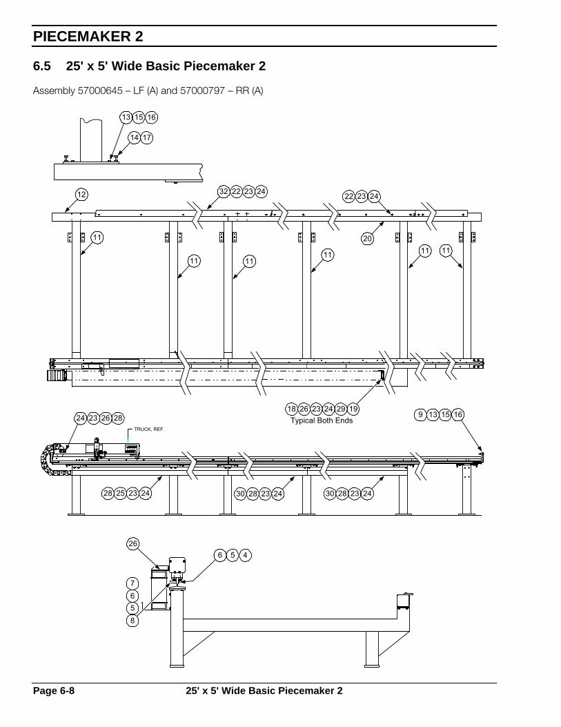
6.5 25' x 5' Wide Basic Piecemaker 2
Assembly 57000645 – LF (A) and 57000797 – RR (A)
ESAB
TRUCK, REF.
26
8567
6 5 4
14 17
13 15 16
12
11
32 22 23 24
11 1111 11 11
20
242322
9 13 15 16
242328302423283024232528
24 23 26 2818 26 23 24 29 19Typical Both Ends
PIECEMAKER 2
Page 6-8 25' x 5' Wide Basic Piecemaker 2

Item Part # Qty Description
1 56998319 1 Beam
2 56998327 1 V-Track
3 A/R Screw, Pan Hd. M6-1.0 x 16mm Lg.
4 A/R Screw, Hex Hd. Cap M10-1.5 x 30mm Lg.
5 56998332 1 Rack, 24 DP,1"Sq. x 72" Long
6 A/R Screw, Hex Hd. Cap M6-1.0 x 40mm Lg.
7 A/R Washer, Flat M6
8 A/R Washer, Lock M6
9 2233835 2 Clip, Rack Derailer
10 56998331 Ref. Stop Bracket
11 459556 2 Rubber Bumper
12 A/R Screw, Hex Hd. Cap M6-1.0 x 16mm Lg.
14 A/R Screw, Soc. Hd. M6-1.0 x 45mm Lg.
15 56998320 Ref. Deck
16 A/R Screw, Hex Hd. Cap M8-1.25 x 20mm Lg.
17 A/R Washer, Flat M8
18 A/R Washer, Lock M8
19 A/R Nut, Hex M6-1.0
20 56998321 1 Truck Assy.
21 185W02 2 Pin, Roll 1/4" Dia. x 7/8" Long
22 A/R Screw, Hex Hd. Cap M10-1.5 x 35mm Lg.
23 A/R Washer, Flat M10
24 A/R Washer, Lock M10
25 56998794 1 Assy., E-Stop Enclosure
26 56998322 1 Carriage, Master
27 57000978 2 Cap, End Tube (4 x 4)
28 56998329 Ref. Bracket, Powertrak Y-Axis
29 56995778 2 Powertrak, 252-1-3-.4
30 A/R Screw, Hex Hd. Cap M8-1.25 x 25mm Lg.
31 57001068 9 Bumper Stop
32 A/R Screw, Soc. Hd. Cap M6-10 x 40mm Lg.
34 56998330 1 Stand, Console Front (LF)
56998324 1 Stand, Console Rear (RR)
35 A/R Screw, Hex Hd. Cap M8-1.25 x 20mm Lg.
36 A/R Screw, Trilobular Th'd. Forming Hex Hd. M6 x 16mm Lg.
Replacement Parts
25' x 5' Wide Basic Piecemaker 2 Page 6-9

37 57001481 15 Tie Cable Mount
38 57000672 2 Brat. Spt. Ptrak.
39 57000996 1 Cover
40 56996084 2 Wiper Way, Fabbed
41 2235167 1 Support, Bearing
42 1006331 1 Bearing, Roller
43 2235164 1 Ring, Snap
44 A/R Washer, Lock M12
45 A/R Washer, Flat M12
46 A/R Nut, Hex M12-1.75
47 16901701 24 Leveler, Hex 1/2-13 x 3
48 A/R Nut, Hex 1/2-13
49 12510133 1 Nameplate
50 954698 3 Label, Warning Gear Pinch Hazard
51 A/R Washer, Star M6
52 2239825 1 Plate, Transformer Support
53 A/R Screw, Flat Hd. M6-1.0 x 16mm Lg.
54 954515 2 Label, Warning Rotating Parts
55 2238956 1 Tag, Metal AMT Member
56 56996459 1 Label, ESAB Logo 3"
57 2061361 2 Label, Warning
58 57000789 1 Assembly, Rail 25 Ft. (LF/RR 5'W)
59 56998341 1 Assembly, Air Slide
60 56998355 Ref. Assembly, Down Draft Table
61 A/R Screw, Hex Hd. Cap M10-1.5 x 25mm Lg.
62 56998490 1 Elect, Package 25 ft. Front/Left Control
63 2091514 1 Label, Warning
64 56996954 1 Cam, Upper Travel LH
65 56998676 1 Limit Switch
66 2239113 1 Switch, Limit Miniature
67 A/R Screw Triobular Th'd. Forming Hex Hd. M6 x 25mm Lg.
68 A/R Screw, Pan Hd. M500.8 x 16mm Lg.
69 A/R Washer, Lock M5
70 A/R Nut, Hex M5-0.8
72 A/R Nut, Hex M8-1.25
73 A/R Screw, But. Hd. Cap M8-1.25 x 25mm Lg.
PIECEMAKER 2
Page 6-10 25' x 5' Wide Basic Piecemaker 2
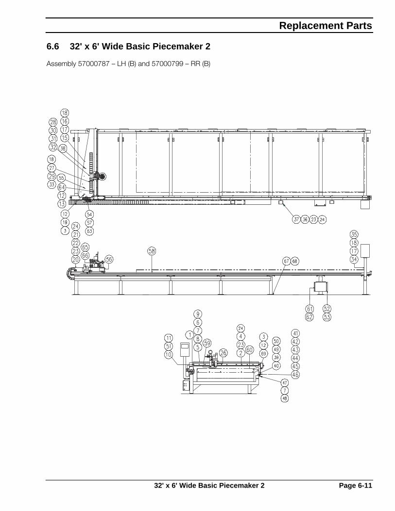
6.6 32' x 6' Wide Basic Piecemaker 2
Assembly 57000787 – LH (B) and 57000799 – RR (B)
Replacement Parts
32' x 6' Wide Basic Piecemaker 2 Page 6-11

Item Part # Qty Description
1 57000636 Ref. Beam
2 57000640 1 V-Track
3 A/R Washer, Interal Star M6
4 A/R Screw, Hex Hd. Cap M10-1.5 x 40mm Lg.
5 57000637 1 Rack, 24 DP 1" Sq. x 84" Long
6 A/R Screw, Hex Hd. Cap M6-1.0 x 40mm Lg.
7 A/R Washer, Flat M6
8 A/R Washer, Lock M6
9 2233835 2 Clip, Rack Derailer
10 56998331 Ref. Bracket, Stop
11 459556 2 Bumper, Rubber
12 A/R Screw, Hex Hd. Cap M6-1.0 x 16mm Lg.
13 A/R Washer, Flat M6
14 A/R Screw, Soc. Hd. M6-1.0 x 20mm Lg.
15 57000638 Ref. Deck
16 A/R Screw, Hex Hd. Cap M8-1.25 x 20mm Lg.
17 A/R Washer, Flat M8
18 A/R Washer, Lock M8
19 A/R Nut, Hex M6-1.0
20 56998321 1 Assembly, Truck
21 185W02 2 Pin, Roll 1/4" Dia. x 7/8" Lg.
22 A/R Screw, Hex Hd. Cap M10-1.5 x 35mm Lg.
23 A/R Washer, Flat M10
24 A/R Washer, Lock M10
26 56998322 1 Assembly, Carriage
27 A/R Nut, Hex M8-1.25
28 56998329 Ref. Bracket, Powertrak Y-Axis
29 56995778 2 Powertrak, 252-I-3.4
30 A/R Screw, Hex Hd. Cap M8-1.25 x 25mm Lg.
33 A/R Screw, But. Hd. Cap M8-1.25 x 25mm Lg.
34 56998330 1 Stand, Console Front (LF)
56998324 1 Stand, Console Rear (RR)
35 A/R Screw, Hex Hd. Cap M8-1.25 x 20mm Lg.
36 A/R Screw, Hex Hd. Cap M10-1.5 x 25mm Lg.
37 57000672 3 Brat., Spt. Ptrak.
38 57001481 20 Tie, Cable Mount
PIECEMAKER 2
Page 6-12 32' x 6' Wide Basic Piecemaker 2

39 57000996 1 Cover
40 56996084 2 Wiper Way, Fabbed
41 2235167 1 Support, Bearing
42 1006331 1 Bearing, Roller
43 2235164 1 Ring, Snap
44 A/R Washer, Lock M12
45 A/R Washer, Flat M12
46 A/R Nut, Hex M12-1.75
47 57001068 12 Bumper Stop
48 A/R Screw, Soc. Hd. Cap M6-1.0 x 40mm Lg.
49 A/R Screw, Trilobular Th'd. Forming Hex Hd. M6-1.0 x 16mm Lg.
50 A/R Screw, Trilobular Th'd. Forming Hex Hd. M6-1.0 x 25mm Lg.
51 A/R Screw, Soc. Hd. Cap M6-1.0 x 45mm Lg.
52 2239825 1 Plate, Transformer Support
53 A/R Screw, Flat Hd. M6-1.00 x 16mm Lg.
54 A/R Screw, Pan Hd. M5-0.8 x 16mm Lg.
55 2238956 1 Tag, Metal AMT Member
56 56996459 1 Label, ESAB Logo 3"
57 A/R Washer, Lock M5
58 57000791 Ref. Assembly, Rail 32 Ft.
59 56998341 Ref. Assembly, Air Slide
60 57000646 Ref. Assembly, Downdraft Table
61 56998378 Ref. Module, PCM875
62 56998490 1 Elect., Package 32ft. Cntrl. Front/Left
63 A/R Nut, Hex M5-0.8
64 56996954 1 Cam, Upper Travel LH
65 56998676 1 Mount, Switch
66 2239113 1 Switch, Limit Miniature
67 16901701 28 Leveler, Hex 1/2-13 x 3
68 A/R Nut, Hex 1/2-13
69 56998794 1 Assy., E-Stop Enclosure
Replacement Parts
32' x 6' Wide Basic Piecemaker 2 Page 6-13
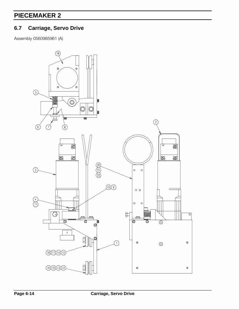
6.7 Carriage, Servo Drive
Assembly 0560985961 (A)
PIECEMAKER 2
Page 6-14 Carriage, Servo Drive

Item Part# Qty Description 1 56998326 1 Carriage
2 0560985984 1 Cover Mtr Prctve
3 0560996401 1 Drive Servo Assy
4 61292652 1 Bolt, Shoulder Soc. Hd. 5/8" Dia. x 2" Lg.
5 2233820 1 Spring, Preload
6 2233819 1 Snub, Spring
7 1 Screw, Hex Hd. Cap M10-1.5 x 45mm Lg.
8 1 Nut, Hex M10-1.5
9 2233823 6 Washer, Thrust
10 2233824 2 Bearing, Thrust
11 63311183 1 Nut, Lock 1/2"-13
12 56998345 4 Wheel, Guide
13 2235115 2 Bushing, Eccentric
14 56998325 2 Stand-Off, Bearing
15 2 Screw, Hex Hd. Cap M8-1.25 x 30mm Lg.
16 2 Washer, Flat M8
17 2 Screw, Hex Hd. Cap M12-1.75 x 40mm Lg.
18 2 Washer, Lock M12
19 57000908 1 Mount Gearbox Planet Bayside
20 56998328 1 Support, Hose
21 2 Screw, Hex Hd. Cap M6-1.0 x 16mm Lg.
22 2 Washer, Lock M6
23 57001403 Ref. Cbl Ay 8/20 10S-0 BS FX
Replacement Parts
Carriage, Servo Drive Page 6-15
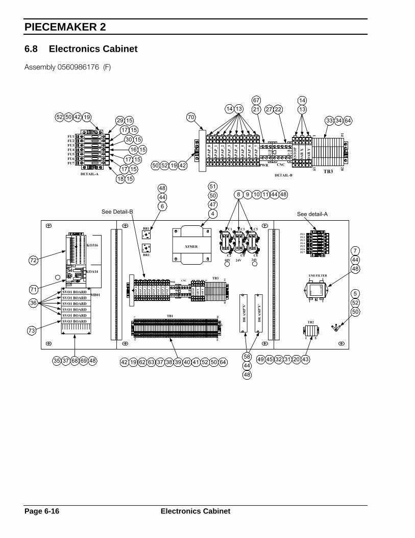
6.8 Electronics Cabinet
Assembly 0560986176 (F)
MCRA40E
MB01
KO316
KOA14
SVO1 BOARD
SVO3 BOARDSVO1 BOARD
SVO1 BOARDSVO1 BOARDSVO1 BOARD
EST
OP
XFMER
511
APA
P_0
APA
P_1
TB1
APA
P_7
APA
P_5
APA
P_6
APA
P_4
APA
P_2
APA
P_3
GE
MCRA40E40E
MCRA
GE
PWR CNC
BR2
BR1
TB3
DR
AM
P'X
'
11658
15
DA
R Y
DA
R X
1
2814
DR
AM
P'Y
'
C3
C424V60V
C2
C1
24VC6
C5
DETAIL-A
FU1
FU6FU7
FU5
FU3FU4
FU2
APA
P_7
APA
P_5
APA
P_6
APA
P_2
APA
P_0
APA
P_1
APA
P_3
APA
P_4
PWR
GE
1
TB2
5
20V
K1
CO
RC
OMFI
LTER
EMI
EMI FILTER
FU6FU5
FU7
FU3FU2FU1
FU4
GE
MCRA40E
DA
R Y
DA
R X
EST
OP
DETAIL-B
CNC 15
TB3
28
1 14
52 50 42 19 29 1517 15
30 15
15
15
15
1518
17
17
16
42195250
7014 13 21
672227 13
14
33 34 64
8 9 10 11 44 48
See detail-A
74448
55250
49 45 32 31 20 43
484458
42 19 62 63 37 38 39 40 41 52 50 64
See Detail-B
72
71
36
73
35 37 68 69 48
48446
5150474
PIECEMAKER 2
Page 6-16 Electronics Cabinet

CUT-OUTIN BOTTOM
DR
AM
P'Y
'
511
11658
15
TB1
EST
OP
APA
P_0
APA
P_1
APA
P_7
APA
P_5
APA
P_6
APA
P_4
APA
P_2
APA
P_3
GE
MCRA40E40E
MCRA
GE
PWR CNCTB3
DA
R Y
DA
R X
1
2814
BR2
BR1
DR
AM
P'X
'
XFMER
60VC2
24VC4
24VC6
C1 C3 C5
28 28
50 65 59 24 23
1246 67
6550 59
25 26 55 56 57
Front view with doorremoved
1
50655924232 53 54
Replacement Parts
Electronics Cabinet Page 6-17

Item Part# Qty Description 1 D-56997893 1 Encl Drl Sabre 1000 Control 2 D-0560986177 1 Drill Pnl Piecemaker Ii 3 A-2046741 8 Spacer 4 A-57001412 1 Transformer Control 120v Pri 50/60hz 5 A-2018994 3 Lug, Solder 6 A-13730469 2 Rectifier Bridge 7 A-0560995369 1 Corcom Filter 8 A-2238601 6 CAPACITOR 4700uf 100VDC 9 A-636612 6 Clamp Mounting Capacitor
10 A-2238605 3 Busbar 11 17615222 3 Resistor 2.2k 5w 12 A-2236401 1 Switch 2 Pole 20a 13 A-0560996138 11 Miniature Relay 14 A-0560989702 11 Mini Relay Socket 15 A-2234477 7 Fuse Block Terminal 16 A-2017107 3 Fuse 2amp Agc2 17 A-2079279 3 Fuse Abc5 18 A-2017327 1 Fuse Abc10 19 A-2234485 6 End Clamp 20 A-2234320 2 End Bracket 21 A-0560995900 1 Contactor, 110vac Four Pole 22 A-0560995899 1 Ge 24vdc Contactor 23 A-2236432 18 Clip Stirrup .23-.47 Dia 24 B-56998446 2 Rail Sectional Clamping 11" Long 25 A-2078865 1 Switch Door Interlock 26 A-56997892 1 Bracket Interlock Switch Mtg 27 A-0560996134 1 Dc Snubber 28 A-57002247 2 Strap, Ground, 12" 29 A-2044277 1 Fuse 10a 250v Mda-10 30 A-2017483 1 Fuse 1a 250v Agc1 31 A-2237990 12 Terminal Block 20-8 Awg Std 32 A-2237991 1 End Cover 20-8 Awg Std 33 A-2237993 14 Terminal Block Mini Dbl Level 34 A-2237994 8 End Cover Mini Dbl Level 35 A-56997158 REF Card Mainboard Mb01 Lcasiob 36 A-56997159 REF Servo-01 Lcasiob 24v 2a 37 A-0560986171 6 Plug Combicon 2 Pos 38 A-0560986172 2 Plug Combicon 4 Pos 39 A-951009 1 Receptacle P/C 6 Pos 40 A-0560986173 4 Plug Combicon 8 Pos 41 A-(8)951339 1 Plug 12 Position 42 A-2234478 AR Mounting Rail Ns 35/7.5 43 A-2234268 AR Mounting Rail Ns 15 44 BIN STOCK AR SCREW M3-0.5 X 12mm POSIDRIVE THD
FORMING 45 BIN STOCK AR SCREW M4-0.7 X 12mm POSIDRIVE THD
FORMING 46 BIN STOCK AR SCREW BUTTON HD M4-0.7 X 12mm
PIECEMAKER 2
Page 6-18 Electronics Cabinet

47 BIN STOCK AR SCREW M5-0.8 X 16mm POSIDRIVE THD FORMING
48 BIN STOCK AR Washer Lock M3 49 BIN STOCK AR Washer Lock M4 50 BIN STOCK AR Washer Lock M5 51 BIN STOCK AR Washer Flat M5 52 BIN STOCK AR SCREW M5-0.8 X 12mm POSIDRIVE THD
FORMING 53 BIN STOCK AR SCREW M10-1.5 X 20mm HEX HD CAP 54 BIN STOCK AR Washer Lock M10 55 BIN STOCK AR Screw, #6-32 X .50 Lg Pan Hd 56 BIN STOCK AR Washer Lock #6 57 BIN STOCK AR Nut #6-32 Hex 58 A-0560986178 2 Pwm Drive 12abe-Es1 6a 20-80v 59 BIN STOCK AR M5-0.8 X 12mm PH SCREW 60 BIN STOCK AR #10-32 X 1/2 Posidrive Thd Forming Screw 61 BIN STOCK AR #10-32 Lock Washer 62 A-2237987 58 Term Block Dbl Level W/Comb 63 A-2237988 1 End Cover Dbl Level Left 64 A/R Term. Block Markers 65 BIN STOCK AR M5-0.8 Hex Nut 66 D-2234274 1 Volt Panel Blank 67 A-0560996135 1 Ac Snubber 68 56995674 REF STANDOFF BRS M3 X 10mm M/F THD 69 BIN STOCK AR SCREW M3-0.5 X 8mm TH'D FORMING 70 57002499 REF Analog Isolation Module 71 56997678 REF. Koa14 Analog Output Board 72 56997165 REF Ko316 Triac Output Board 73 0560999106 REF Sv03 60v 7a
* Quantity determined by machine configuration.
Replacement Parts
Electronics Cabinet Page 6-19
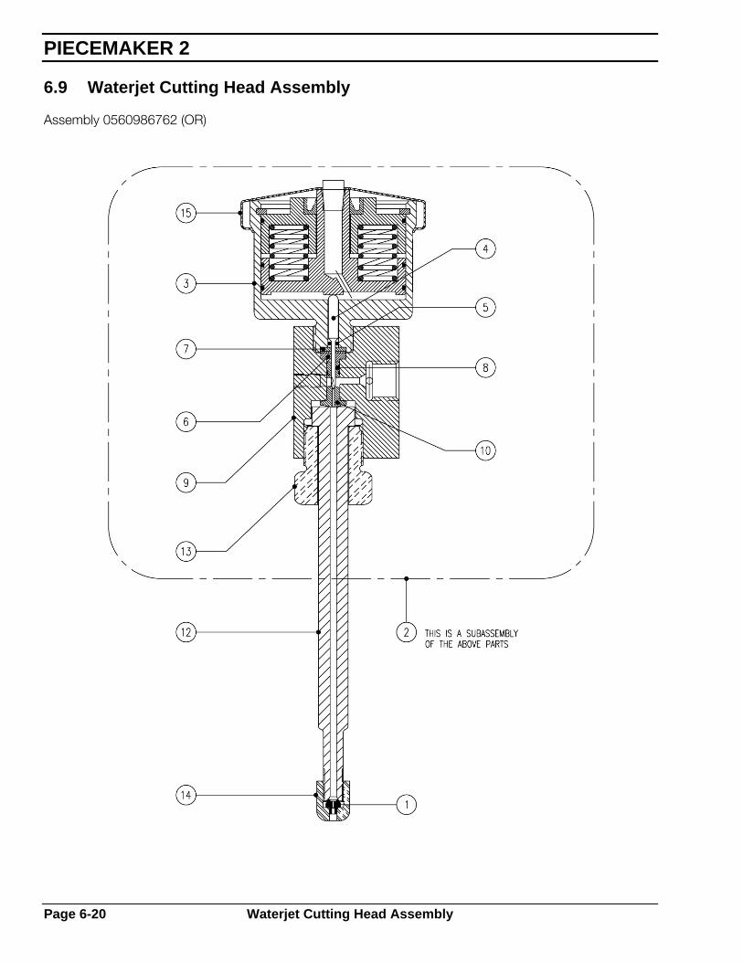
6.9 Waterjet Cutting Head Assembly
Assembly 0560986762 (OR)
PIECEMAKER 2
Page 6-20 Waterjet Cutting Head Assembly
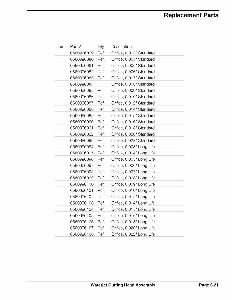
Item Part # Qty Description
1 0560996079 Ref. Orifice, 0.003" Standard
0560996080 Ref. Orifice, 0.004" Standard
0560996081 Ref. Orifice, 0.005" Standard
0560996082 Ref. Orifice, 0.006" Standard
0560996083 Ref. Orifice, 0.007" Standard
0560996084 1 Orifice, 0.008" Standard
0560996085 Ref. Orifice, 0.009" Standard
0560996086 Ref. Orifice, 0.010" Standard
0560996087 Ref. Orifice, 0.012" Standard
0560996088 Ref. Orifice, 0.014" Standard
0560996089 Ref. Orifice, 0.015" Standard
0560996090 Ref. Orifice, 0.016" Standard
0560996091 Ref. Orifice, 0.018" Standard
0560996092 Ref. Orifice, 0.020" Standard
0560996093 Ref. Orifice, 0.022" Standard
0560996094 Ref. Orifice, 0.003" Long Life
0560996095 Ref. Orifice, 0.004" Long Life
0560996096 Ref. Orifice, 0.005" Long Life
0560996097 Ref. Orifice, 0.006" Long Life
0560996098 Ref. Orifice, 0.007" Long Life
0560996099 Ref. Orifice, 0.008" Long Life
0560996100 Ref. Orifice, 0.009" Long Life
0560996101 Ref. Orifice, 0.010" Long Life
0560996102 Ref. Orifice, 0.012" Long Life
0560996103 Ref. Orifice, 0.014" Long Life
0560996104 Ref. Orifice, 0.015" Long Life
0560996105 Ref. Orifice, 0.016" Long Life
0560996106 Ref. Orifice, 0.018" Long Life
0560996107 Ref. Orifice, 0.020" Long Life
0560996108 Ref. Orifice, 0.022" Long Life
Replacement Parts
Waterjet Cutting Head Assembly Page 6-21

Item Part # Qty Description
2 0560996117 1 Actuator Assembly
3 0560996118 Ref. Actuator, Normally Closed
4 0560996119 Ref. Stem
5 0560996120 Ref. O-ring
6 0560996121 Ref. Back-up Ring, Brass
7 0560996122 Ref. Back-up Ring, Stainless Steel
8 0560996123 Ref. Seal Assembly
9 0560996508 Ref. Valve Body
10 0560996509 Ref. Valve Seat
12 0560996543 1 Nozzle Tube, 3/8" Dia. x 8" Long
13 0560996518 1 Valve Nut
14 0560996546 1 Nut, 3/8" Dia. Tube Nozzle
15 0560996520 1 Cover Actuator
PIECEMAKER 2
Page 6-22 Waterjet Cutting Head Assembly

6.10 Waterjet Addition Assembly
Assembly 0560986765 (A)
Replacement Parts
Waterjet Addition Assembly Page 6-23

Item Part # Qty Description
1 0560998097 1 Washer, 5000 psi pressure
2 0560986758 50ft. Hose, 3/8" ID. 5000 psi
3 0560986759 2 Fitting, 3/8" NPT Swivel
4 0560987050 1 Elbow, 3/8" NPTF Street Elbow
5 0560986761 1 Adapter, 3/8" NPT – 3/8" HP
6 0560986762 1 Assy, Wjet Only Cutting Head
7 0560996732 1 Tube Fitting, 1/8" NPT – ¼" OD
8 90858001 5ft. Tubing, ¼" OD Plastic
9 0560986763 1 Adapter Block
10 0560987044 1 Torch Mount
11 0560987045 1 Bracket, Lift
12 2081885 1 Ball Slide, CBU
13 0560986764 1 Slide Mount
14 0560986757 1 Brkt, Waterjet Station Mtg.
15 0560986766 2 Brace, Slide Mtg.
16 0560986652 4 Handle, Adjust. M8-1.25 x 25mm Lg.
17 2212144 1 Junction Box
18 0560995395 1 Valve Stack of 2
19 2213466 1 Air Cylinder
20 2213468 1 Cyl. Foot Mount
22 63340230 1 Nut 30005 STLZPC 0.625
23 810Z30 3 Adapter, Air ¼" NPT to 5/8"-18 RH
24 2059603 1 Tee, ¼" NPT Female
25 2135688 1 Nipple, ¼" NPT
26 23079995 5ft. 3/8" ID Hose
27 03Z74 2 Hose Nipple, ‘B’ to 3/8" ID Hose
28 836Z40 2 Nut, 5/8"-18 RF Female
29 39Z91 2 Ferrule
PIECEMAKER 2
Page 6-24 Waterjet Addition Assembly
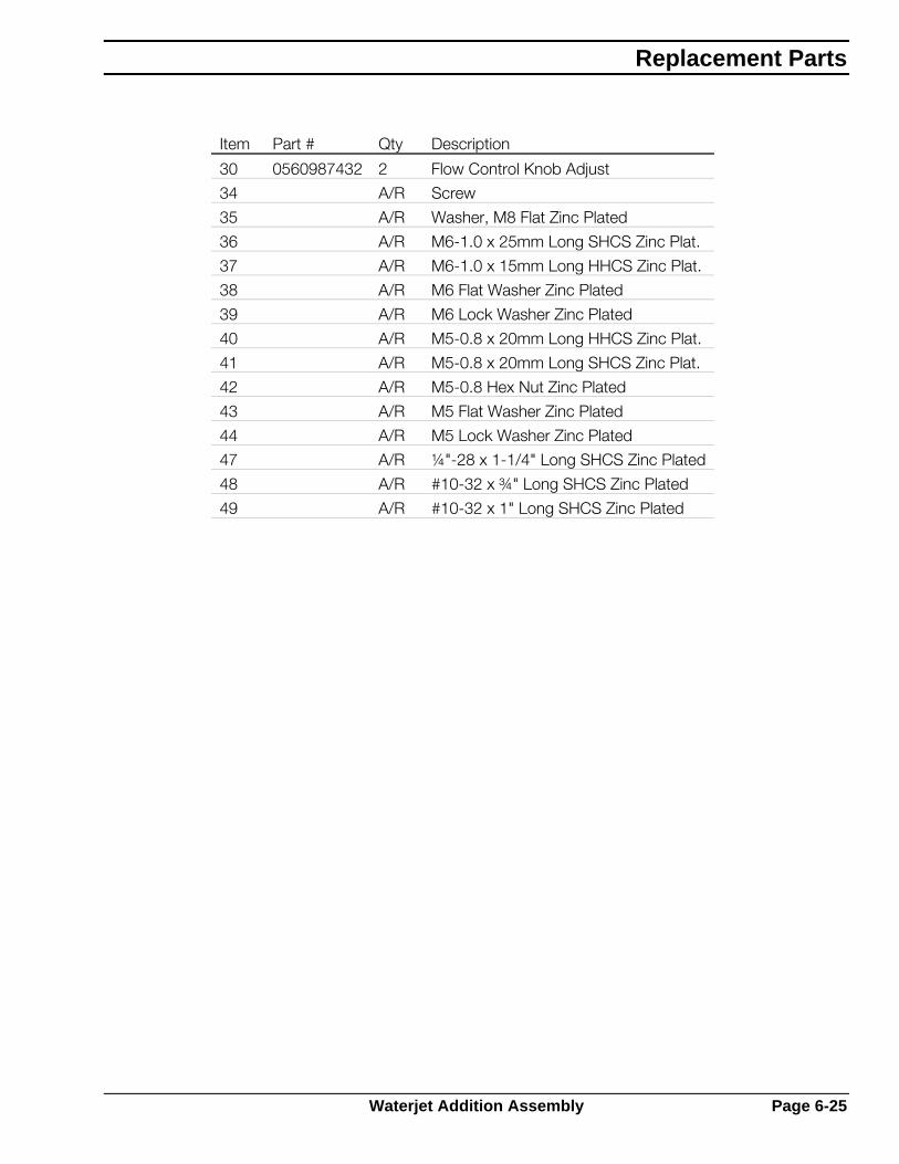
Item Part # Qty Description
30 0560987432 2 Flow Control Knob Adjust
34 A/R Screw
35 A/R Washer, M8 Flat Zinc Plated
36 A/R M6-1.0 x 25mm Long SHCS Zinc Plat.
37 A/R M6-1.0 x 15mm Long HHCS Zinc Plat.
38 A/R M6 Flat Washer Zinc Plated
39 A/R M6 Lock Washer Zinc Plated
40 A/R M5-0.8 x 20mm Long HHCS Zinc Plat.
41 A/R M5-0.8 x 20mm Long SHCS Zinc Plat.
42 A/R M5-0.8 Hex Nut Zinc Plated
43 A/R M5 Flat Washer Zinc Plated
44 A/R M5 Lock Washer Zinc Plated
47 A/R ¼"-28 x 1-1/4" Long SHCS Zinc Plated
48 A/R #10-32 x ¾" Long SHCS Zinc Plated
49 A/R #10-32 x 1" Long SHCS Zinc Plated
Replacement Parts
Waterjet Addition Assembly Page 6-25

6.11 Servo Drive Assembly with Planetary Gearbox
Assembly 0560996401 (F)
Item Part # Qty Description
1 0560996402 1 DC Servo Motor with Encoder
2 0560996403 1 Planetary Gearbox
3 57000911 1 Pinion
4 2 Set Screw, M4-0.7 x 5mm
5 0560985984 1 Motor Cover
PIECEMAKER 2
Page 6-26 Servo Drive Assembly with Planetary Gearbox

6.12 Interface Box Assembly (J-Box)
Assembly 0560986783 (B)
Item Part # Qty Description
1 0560986784 1 J-Box Enclosure
2 527376 6 Strain Relief
3 2062151 6 Lock Nut
4 2234473 21 Terminal Block, Mini
5 2234320 2 End Bracket
6 2234476 6 End Cover, Mini
7 2234268 A/R NS-15 Mounting Rail
8 A/R Screw, M4-0.7 x 12mm, PosiDrive, Thread Forming
9 A/R Flat Washer, M4
10 A/R Lock Washer, M4
11 57001431 1 Drilled Panel
Replacement Parts
Interface Box Assembly (J-Box) Page 6-27

6.13 Plate Rider, Plasma
Assembly 2238229 (D)
Item Part # Qty Description
1 2238228 1 Shield/Rider Plate Plas. 1.25D
2 640400 1 Clamp, Hose
3 2238227 6 Bearing Ball Transfer w/Clip
PIECEMAKER 2
Page 6-28 Plate Rider, Plasma
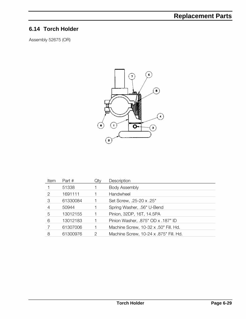
6.14 Torch Holder
Assembly 52675 (OR)
Item Part # Qty Description
1 51338 1 Body Assembly
2 1691111 1 Handwheel
3 61330084 1 Set Screw, .25-20 x .25"
4 50944 1 Spring Washer, .56" U-Bend
5 13012155 1 Pinion, 32DP, 16T, 14.5PA
6 13012183 1 Pinion Washer, .875" OD x .187" ID
7 61307006 1 Machine Screw, 10-32 x .50" Fill. Hd.
8 61300976 2 Machine Screw, 10-24 x .875" Fill. Hd.
Replacement Parts
Torch Holder Page 6-29

6.15 Lift, motorized
Assembly 57000381 (C)
REDBLK
VIEW A-A
Motor not shown this view
A
A
22
1
20
171918
8
914 13
4
7
112
12
SEC B-B
1/8" DRL & INSTALL1/8"-.5 ROLL PIN
15
1016
8
B B
PIECEMAKER 2
Page 6-30 Lift, motorized

Item Part# Qty Description
1 P-66402 1 Motor - Gearbox (Esab # 4-630-480)
2 P-66403 5 Bearing - Fafner S1kcd
3
4 P-51335 1 Snap Ring
5
6
7 57000674 1 Brk-A-Way Budget Torch Body
8 41016193 1 Motor Plate
9 41016195 1 Electric Bearing Plate
10 41016197 1 Pinion
11 66386 8 Washer - 1/4"I.D. X .03 Thk
12 62250519 4 Poll Pin %%C1/4 X 1"
13 64302996 1 %%C1/4" Id Lock Washer
14 63300100 1 1/4-20 Unc Nut Hex
15 61307910 3 Scr Pan Hd 10-32 Unf X 1/8
16 62240032 1 Roll Pin %%C1/8 X 1/2"
17 61301913 2 Scr Rnd Hd Mach 10-32 X 7/8"
18 64304050 2 Flat Wshr #10
19 63300917 2 Nut Hex 10-32 Unf
20 61301921 1 Scr Rnd Hd Mach 10-32 Unf X 5/8"
21 950904 2 Pan Dnf 18-250 Fim Male 18-22 Ins Coupler
22 56998729 1 Cover Lift Motor
Replacement Parts
Lift, motorized Page 6-31

6.16 Main Truck Assembly
Assembly 56998321 (J)
40 FT-LBS. TORQUETIGHTEN BOLT TO
scale: 1=2.5
PRELOAD SPRING SET TO
LENGTH (40 LBS)1-3/8" COMPRESSED
1
152 3
29
8
129 10 11
20
1934
181715161315
4111312
373635
42414038
43
4 5 6
7
2122 23 24
25 26
27
3130
PIECEMAKER 2
Page 6-32 Main Truck Assembly

Item Part # Qty Description
1 56998323 1 Truck ( + Cap and Drive Mnt Brkt)
2 08S11016 8 Screw, M8-1.25x16mm Hex Head
3 08W10082 8 Lock Washer, M8
4 12S11070 5 Screw, M12-1.75x70mm
5 12W01140 3 Flat Washer, M12
6 12W10122 3 Lock Washer, M12
7 2235086 2 Retaining Ring
8 2235314 2 Ball Bearing
9 56997091 2 Wheel Axle
10 12S11030 4 Screw, M12-1.75x30mm hex head
11 12W10122 6 Lock Washer, M12
12 12W01140 6 Flat Washer, M12
13 2235315 4 Guide Bearing
15 08W01090 12 Flat Washer, M8
16 56997089 2 Eccentric Post
17 08W10082 2 Lock Washer, M8
18 08S11050 2 Screw, M8-1.25x500mm hex head
19 0560996401 1 Servo Drive Assembly with Planetary Gearbox
20 61292666 1 Shoulder Bolt, 5/8x2-1/2 soc head
21 2233820 1 Preload Spring
22 2233819 1 Spring Nub
23 10S10035 1 Screw, M10-1.5x35mm hex head
24 10N01150 1 Hex Nut, M10-1.5
25 2233823 4 Thrust Washer
26 2233824 2 Thrust Bearing
27 63311183 1 Locking Hex Nut, ½-13
29 56997092 2 Rail Scraper
30 08S11025 2 Screw, M8-1.25x25mm hex head
31 08S10082 2 Flat Washer, M8
32 56997720 2 Guide Bearing Spacer
34 56998677 1 Home Switch Cam
35 56997595 1 Limit Switch Bracket
36 06S10016 2 Screw, M6-1.0x16mm hex head
38 57002257 1 Limit Switch
40 2 Screw, M4-.7x30mm pan head
41 2 Lock Washer, M4
42 2 Hex Nut, M4
43 57000908 1 Gearbox Mount
Replacement Parts
Main Truck Assembly Page 6-33

6.17 Y Axis Carriage Assembly (Not current--Pre Planetary Drive)
Assembly 56998322 (A)
PIECEMAKER 2
Page 6-34 Y Axis Carriage Assembly (Not current--Pre Planetary Drive)
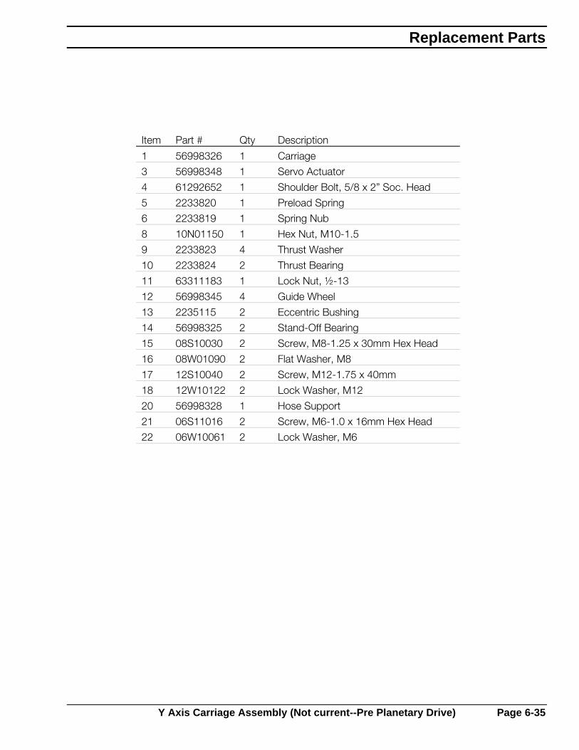
Item Part # Qty Description
1 56998326 1 Carriage
3 56998348 1 Servo Actuator
4 61292652 1 Shoulder Bolt, 5/8 x 2” Soc. Head
5 2233820 1 Preload Spring
6 2233819 1 Spring Nub
8 10N01150 1 Hex Nut, M10-1.5
9 2233823 4 Thrust Washer
10 2233824 2 Thrust Bearing
11 63311183 1 Lock Nut, ½-13
12 56998345 4 Guide Wheel
13 2235115 2 Eccentric Bushing
14 56998325 2 Stand-Off Bearing
15 08S10030 2 Screw, M8-1.25 x 30mm Hex Head
16 08W01090 2 Flat Washer, M8
17 12S10040 2 Screw, M12-1.75 x 40mm
18 12W10122 2 Lock Washer, M12
20 56998328 1 Hose Support
21 06S11016 2 Screw, M6-1.0 x 16mm Hex Head
22 06W10061 2 Lock Washer, M6
Replacement Parts
Y Axis Carriage Assembly (Not current--Pre Planetary Drive) Page 6-35

6.18 Torch Lifter Assembly
Assembly 0560985428 (D)
CARRIAGE (REF)
AIR SCHEMATIC
CYLINDER
50 TO 55 PSIGADJUST FOR
LIFT
90-100 PSIGCLEAN DRY AIR
40-60 PSI
PT 20
Alternate torchmounting configuration
36 42 41 40
39
37394839
44 424140
424140
40414245
43
3920
232221
1917
292827
25
12
38
36
3335
46 47 50
49 28 31 32
1051
30
1 2
9
6
3 4 5
7 8
13 14 5
24
26
1617
Note: Items #21,#22,#23 may need to be mounted at the top of the air cylinder, depending on type of torch used.
PIECEMAKER 2
Page 6-36 Torch Lifter Assembly

Item Part # Qty Description
1 2213466 1 Air Cylinder, 2” stroke
2 63340230 1 Hex Jam Nut, 5/8-18
3 2213468 1 Cylinder Mount Foot
4 2 Screw, ¼-20x1/2 hex head
5 2 Flat Washer, ¼
6 567596 1 Muffler, 1/8” brass
7 2 Hex Jam Nut, 5/16-24
8 2 Flat Washer, 5/16
9 2136736 1 Adaptor Elbow, 5/32 tube x 1/8 NPT
10 57001681 4 ft Plastic Tubing, 5/32 O.D. Spark Res.
12 1000381 1 Rubber Bumper
13 2213465 1 Air Slide Retainer
14 2 Screw, ¼-20x5/8 hex soc head
16 2081885 1 Linear Slide
17 8 Screw, #10-32x5/8 Hex soc
19 56995616 1 Air Slide Retaining Screw
20 52675 1 Adjustable Torch Holder
21 2 Screw, ¼-20x1.5” Hex soc head
22 56995572 1 Torch Clamp
23 56995571 1 Air Slide Torch Holder
24 2238229 1 Plate Rider Assembly
25 2 M6 Flat Washer
26 640400 A/R Worm Clamp
27 2213470 1 Slide Adaptor Plate
28 61340089 6 Screw, ¼-20xx3/4 soc head
29 4 Lock Washer, ¼
30 2136727 1 Elbow, Tubing
31 2 Hex Nut, ¼”
32 2 Lock Washer, ¼”
33 2059553 1 Air Valve
35 0560987291 1 Exhaust Speed Control, .25" NPT
36 182W82 2 Pipe Elbow, St. 90 Deg ¼ M x ¼ F
37 2135688 1 Nipple, ¼ NPT
38 522368 1 Air Regulator
39 810Z30 1 Air Adaptor
40 836Z40 4 Air Nut
41 03Z73 2 Nipple, ¼ NPT
42 39Z83 2 Ferrule, ¼” Hose
Replacement Parts
Torch Lifter Assembly Page 6-37
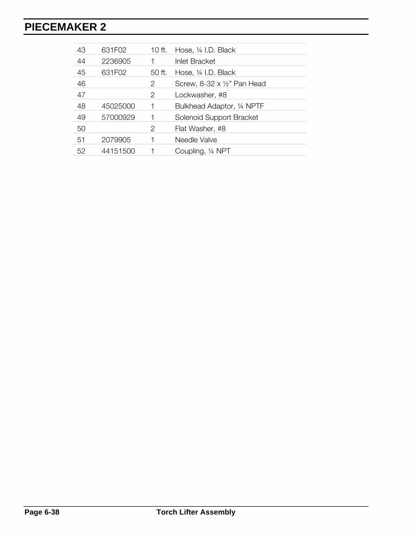
43 631F02 10 ft. Hose, ¼ I.D. Black
44 2236905 1 Inlet Bracket
45 631F02 50 ft. Hose, ¼ I.D. Black
46 2 Screw, 8-32 x ½” Pan Head
47 2 Lockwasher, #8
48 45025000 1 Bulkhead Adaptor, ¼ NPTF
49 57000929 1 Solenoid Support Bracket
50 2 Flat Washer, #8
51 2079905 1 Needle Valve
52 44151500 1 Coupling, ¼ NPT
PIECEMAKER 2
Page 6-38 Torch Lifter Assembly

6.19 Electronics Cabinet Assembly (non current)
Assembly 56998490 (G)
Replacement Parts
Electronics Cabinet Assembly (non current) Page 6-39

Item Part # Qty Description
1 56995491 1 Enclosure
2 56998492 1 Panel
3 57001412 1 Transformer, 18/45V 12A 50/60Hz
5 2238601 4 Capacitor, 4700µF, 100VDC
6 636612 4 Capacitor Mounting Clamp
7 2238605 2 Busbar
8 17615222 2 Resistor, 2.2K 5W
9 13730469 2 Rectifier
10 52503 5 Strain Relief
11 2236401 1 Switch
12 2234473 25 Terminal Block, Mini
13 2234476 1 End Cover, Mini
14 2234320 4 End Bracket
15 2234268 A/R Mounting Rail
16 2235711 3 Relay Socket, Rail Mounting
17 2010924 3 DC Relay
18 2234485 2 End Clamp
19 2234478 A/R Mounting Rail
20 2234477 4 Fuse Block, Rail Mounted
21 2044278 1 Fuse, 15A
22 2079279 1 Fuse, N-T Delay, 5A 250V
23 2017327 1 Fuse, N-T Delay Ceramic, 10A 250VAC
24 2017107 1 Fuse, 2A
25 0560985303 1 DC Relay, DPDT 15A, Socket-Mounting
26 0560985302 1 Relay Socket
27 56998792 1 Connector, 4 Socket
28 0560986178 2 PWM Drive
29 950762 1 Connector, 19 Pin
30 996514 1 Connector, 5 Socket
31 993952 1 Connector, 6 Socket
32 13734545 1 Connector, 3 Pin
33 2017021 1 Connector, 6 Pin
34 182W62 1 Connector, 3 Socket
35 636692 1 Connector, 10 Socket
36 2238415 Power Supply Cable Assembly
37 56998498 Cable Assembly, 5 Conductor
38 56998502 Cable Assembly, 6 Conductor
39 2236766 Cable Assembly, 3 Conductor
PIECEMAKER 2
Page 6-40 Electronics Cabinet Assembly (non current)

40 2238779 Cable Assembly, 6 Conductor
41 56997104 Cable Assembly, 3 Conductor
42 2238311 Cable Assembly, 10 Conductor
43 8812355 25' Cable, 3 Conductor 14 Gauge
44 2017587 1 Plug, 110V
45 672238 8 Ring Terminal
46 51876 8 Cable Label
48 2136670 1 AC Line Filter
49 2078865 1 Interlock Switch
50 A/R Screw, M3-0.5 x 10mm, Pan Hd.
51 A/R Screw, M3-0.5 x 16mm, Thread-Forming, Pan Hd.
52 A/R Screw, M4-0.7 x 8mm, Pan Hd.
53 A/R Screw, M4-0.7 x 25mm, Pan Hd.
54 A/R Screw, M4-0.7 x 10mm, Pan Hd.
55 A/R Screw, M5-0.8 x 16mm, Thread-Forming, Pan Hd.
56 A/R Screw, #6-32 x 1/2", Pan Hd.
57 A/R Lock Washer, #6
58 A/R Lock Washer, M3
59 A/R Lock Washer, M4
60 A/R Lock Washer, M5
61 A/R Flat Washer, M5
62 A/R Hex Nut, M3
63 A/R Hex Nut, M4
65 56998787 Cable Assembly, 4 Conductor 20 Gauge
66 56998826 1 Ground Strap, 7"
67 A/R Screw, M4-0.7 x 8mm, Thread-Forming
68 A/R Screw, #6-32 x 3/8", Thread-Forming
69 A/R Screw, M3-0.5 x 10mm, Thread-Forming
70 2062196 2 Ring Terminal
71 73006899 A/R Cable, #8
73 A/R Washer, Star #6
74 A/R Screw, M5-0.8 x 8mm Posi-Drive Thd. Forming
Replacement Parts
Electronics Cabinet Assembly (non current) Page 6-41

6.20 E-Stop Box Assembly
Assembly 56998794 (A)
Item Part # Qty Description
1 56998793 1 Enclosure
2 51452 1 Connector Receptacle
3 93301401 1 Push Button Switch
4 2236275 1 Contact and Switch Base
5 2236276 1 E-Stop Label
6 A/R Screw, M3-0.5 x 10mm, Pan Hd.
7 A/R Lock Washer, M3
8 A/R Hex Nut, M3
9 93092002 A/R Wire, 20 AWG, 600 V, White
10 93092006 A/R Wire, 20 AWG, 600 V, Blue
PIECEMAKER 2
Page 6-42 E-Stop Box Assembly

6.21 Lite Touch
Assembly 57000412 (A)
Item Part # Qty Description
1 57000375 1 Lite Touch Mounting Plate
2 57000376 1 Lite Touch End Plate
3 8996526 1 O-Ring, .145" ID x .07" Buna-70A
4 57000365 2 Ball Spring Plunger, 5/16"-18
5 56999182 1 Linear Lift
6 57000377 1 Torch Mounting Bracket
7 57000411 1 Way Bellows
8 4 Screw, M5-0.8 x 12mm, FHS
9 2 Screw, 1/4"-20, SHCS
10 2 Screw, 1/4"-20, FHS
11 2234142 1 Hex Nipple, 10-32 x 1/8" ID Hose
12 56999181 1 L-Fitting Adaptor, 10-32
13 1 Carriage Bolt, M12-1.75
14 1 Jam Nut, M12
15 A/R Double-Sided Tape
16 2 Screw, M6-1.0 x 16mm, SHCS
Replacement Parts
Lite Touch Page 6-43

6.22 Soft Touch OMNI Interface Box
Assembly 2234691 (N)
PIECEMAKER 2
Page 6-44 Soft Touch OMNI Interface Box

Item Part # Qty Description
1 2234723 1 Junction Box
2 0560996490 0560998065
1 Pressure Switch OMNI Pressure Switch Kit (for pre-May 1999 units)
3 2234473 12 Terminal Block, Mini
4 2234320 2 End Bracket, Mini
5 2234476 1 End Cover, Mini
6 2234268 4" Mounting Rail
7 2234480 A/R Ferrule, 20 Ga.
8 897W34 2 Rubber Grommet
9 527376 1 Strain Relief
10 881358 2 Lock Nut, M4
11 3 Hex Nut, M3-0.5
12 3 Screw, M3-0.5 x 16mm, Slotted Hd.
13 2 Screw, M4-0.7 x 12mm, Thread-Forming
14 04W10041 2 Lock Washer, M4
15 04W01044 2 Flat Washer, M4
16 2058365 2 Hole Seal
17 93122006 48" Wire, Blue, 20 Ga 300V
18 17615222 1 Resistor
19 526652 1 Strain Relief
20
21 57002575 1 Tube, Y-Union, 1/4"
22 2062561 2 Connector Pin
23 90863063 A/R Heatshrink Tubing
24 57001431 1 Panel
25 2234117 5" Plastic Tubing, 1/8" I.D.
26 2237459 2 Wire Lug
27
Replacement Parts
Soft Touch OMNI Interface Box Page 6-45

6.23 Lite Touch with Collision
Assembly 57000382 (C)
Item Part # Qty Description
1 57000375 1 Lite Touch Mounting Plate
2 57000376 1 Lite Touch End Plate
3 8996526 1 O-Ring, .145" ID x .07" Buna-70A
4 57000365 2 Ball Spring Plunger, 5/16"-18
5 56999182 1 Linear Lift
6 57000377 1 Torch Mounting Bracket
7 57000411 1 Way Bellows
8 57000378 1 Crash Mounting V-Block
9 57000322 4 Ball Spring Plunger, M12
10 57000379 1 Mushroom Head
PIECEMAKER 2
Page 6-46 Lite Touch with Collision
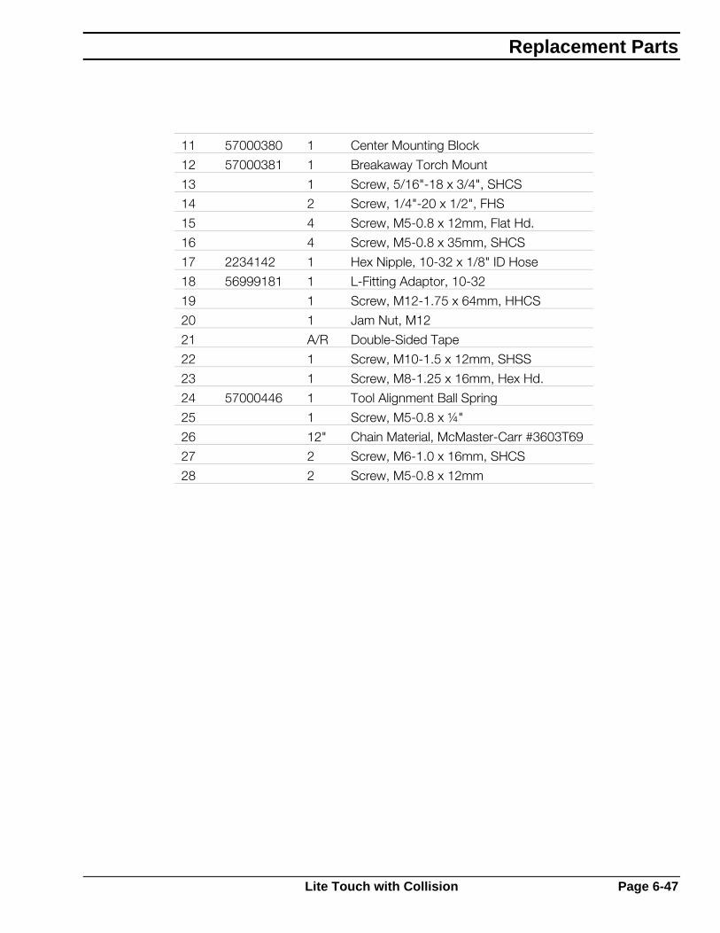
11 57000380 1 Center Mounting Block
12 57000381 1 Breakaway Torch Mount
13 1 Screw, 5/16"-18 x 3/4", SHCS
14 2 Screw, 1/4"-20 x 1/2", FHS
15 4 Screw, M5-0.8 x 12mm, Flat Hd.
16 4 Screw, M5-0.8 x 35mm, SHCS
17 2234142 1 Hex Nipple, 10-32 x 1/8" ID Hose
18 56999181 1 L-Fitting Adaptor, 10-32
19 1 Screw, M12-1.75 x 64mm, HHCS
20 1 Jam Nut, M12
21 A/R Double-Sided Tape
22 1 Screw, M10-1.5 x 12mm, SHSS
23 1 Screw, M8-1.25 x 16mm, Hex Hd.
24 57000446 1 Tool Alignment Ball Spring
25 1 Screw, M5-0.8 x ¼"
26 12" Chain Material, McMaster-Carr #3603T69
27 2 Screw, M6-1.0 x 16mm, SHCS
28 2 Screw, M5-0.8 x 12mm
Replacement Parts
Lite Touch with Collision Page 6-47

6.24 Rail, 16' x 5' Wide
Assembly 57000788 (C)
FRONT LEFT ARRANGEMENT
ESAB
TRUCK, REF.
11
13 3 2
111111
20 25
24
23
2221
18 34 23 24 363223 24 31 33
23 24 33 37 37 33 23 241714
9131516
131516
31
8567
6 5 4
View A-A
14 17
13 15 16
A A
PIECEMAKER 2
Page 6-48 Rail, 16' x 5' Wide

Item Part # Qty Description
1 57000641 1 Rail, 16ft. Lg.
2 57000691 1 Rack, 24 DP 3/4 x 2 X 30"
3 56998346 2 Rack, 24 DP 3/4" x 2" x 72" Lg.
4 A/R Screw, Hex Hd. Cap M6-1.0 x 30mm Lg.
5 A/R Washer, Flat M6
6 A/R Washer, Lock M6
7 2233835 2 Clip, Rack Derailer
8 A/R Screw, Hex Cap M6-1.0 x 16mm
9 56995727 2 Stop, Rail
11 56998335 4 Cradle
13 A/R Screw, Hex Hd. Cap M10-1.5 x 30mm Lg.
14 A/R Screw, Hex Hd. Cap M12-1.75 x 45mm Lg.
15 A/R Washer, Flat M10
16 A/R Washer, Lock M10
17 A/R Nut, Hex M12-1.75
18 57000937 2 Bracket, Clamp
20 57000639 1 Tube, Support Floating Rail
21 57000655 1 Rail, Floating
22 A/R Screw, Hex Hd. Cap M8-1.25 x 20mm Lg.
23 A/R Washer, Flat M8
24 A/R Washer, Lock M8
25 A/R Scr. Soc. Hd. Set F.P. M6-1.0 x 12 Lg.
26 16901701 16 Leveler, Hex 1/2 –13 X 3 inch
27 51424 1 Gauge Rack
31 56998340 Ref. Bracket, Powertrak X-Axis
32 56996493 1 Powertrak, 252P-II-4.7R-16' Travel
33 A/R Screw, Hex Hd. Cap M8-1.25 x 16mm Lg.
34 A/R Screw, But. Hd. Cap M8-1.25 x 16mm Lg.
36 A/R Nut, Hex M8-1.25
37 0560986300 1 Tray, Powertrak
38 0560986299 1 Tray, Powertrak
Replacement Parts
Rail, 16' x 5' Wide Page 6-49

6.25 Rail, 25' x 5' Wide
Assembly 57000789 (B)
ESAB
TRUCK, REF.
26
8567
6 5 4
14 17
13 15 16
12
11
32 22 23 24
11 1111 11 11
20
242322
9 13 15 16
242328302423283024232528
24 23 26 2818 26 23 24 29 19Typical Both Ends
PIECEMAKER 2
Page 6-50 Rail, 25' x 5' Wide
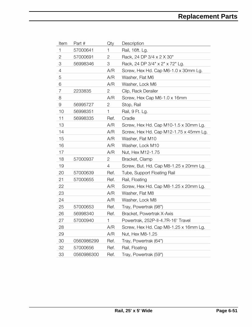
Item Part # Qty Description
1 57000641 1 Rail, 16ft. Lg.
2 57000691 2 Rack, 24 DP 3/4 x 2 X 30"
3 56998346 3 Rack, 24 DP 3/4" x 2" x 72" Lg.
4 A/R Screw, Hex Hd. Cap M6-1.0 x 30mm Lg.
5 A/R Washer, Flat M6
6 A/R Washer, Lock M6
7 2233835 2 Clip, Rack Derailer
8 A/R Screw, Hex Cap M6-1.0 x 16mm
9 56995727 2 Stop, Rail
10 56998351 1 Rail, 9 Ft. Lg.
11 56998335 Ref. Cradle
13 A/R Screw, Hex Hd. Cap M10-1.5 x 30mm Lg.
14 A/R Screw, Hex Hd. Cap M12-1.75 x 45mm Lg.
15 A/R Washer, Flat M10
16 A/R Washer, Lock M10
17 A/R Nut, Hex M12-1.75
18 57000937 2 Bracket, Clamp
19 4 Screw, But. Hd. Cap M8-1.25 x 20mm Lg.
20 57000639 Ref. Tube, Support Floating Rail
21 57000655 Ref. Rail, Floating
22 A/R Screw, Hex Hd. Cap M8-1.25 x 20mm Lg.
23 A/R Washer, Flat M8
24 A/R Washer, Lock M8
25 57000653 Ref. Tray, Powertrak (98")
26 56998340 Ref. Bracket, Powertrak X-Axis
27 57000940 1 Powertrak, 252P-II-4.7R-16' Travel
28 A/R Screw, Hex Hd. Cap M8-1.25 x 16mm Lg.
29 A/R Nut, Hex M8-1.25
30 0560986299 Ref. Tray, Powertrak (64")
32 57000656 Ref. Rail, Floating
33 0560986300 Ref. Tray, Powertrak (59")
Replacement Parts
Rail, 25' x 5' Wide Page 6-51
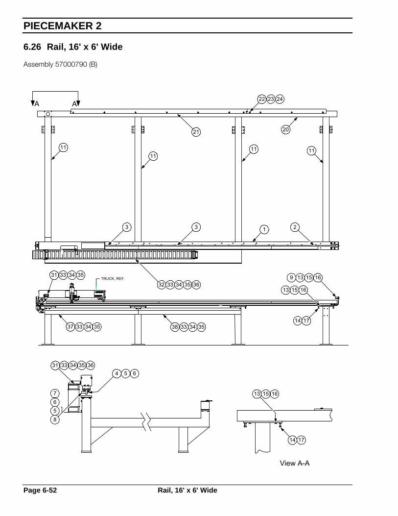
6.26 Rail, 16' x 6' Wide
Assembly 57000790 (B)
TRUCK, REF.
ESAB
1111
11 11
2021
22 23 24
3 3 21
32 33 34 35 36
31 33 34 35
37 33 34 35 38 33 34 351714
13 15 16
1615139
31
8567
4 5 633 34
A A
14 17
13 15 16
View A-A
35 36
PIECEMAKER 2
Page 6-52 Rail, 16' x 6' Wide
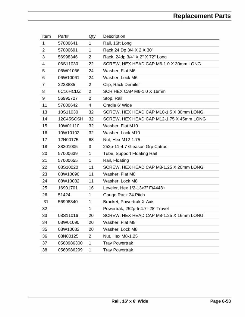
Item Part# Qty Description
1 57000641 1 Rail, 16ft Long
2 57000691 1 Rack 24 Dp 3/4 X 2 X 30"
3 56998346 2 Rack, 24dp 3/4" X 2" X 72" Long
4 06S11030 22 SCREW, HEX HEAD CAP M6-1.0 X 30mm LONG
5 06W01066 24 Washer, Flat M6
6 06W10061 24 Washer, Lock M6
7 2233835 2 Clip, Rack Derailer
8 6C16HCDZ 2 SCR HEX CAP M6-1.0 X 16mm
9 56995727 2 Stop, Rail
11 57000642 4 Cradle 6' Wide
13 10S11030 32 SCREW, HEX HEAD CAP M10-1.5 X 30mm LONG
14 12C45SCSH 32 SCREW, HEX HEAD CAP M12-1.75 X 45mm LONG
15 10W01110 32 Washer, Flat M10
16 10W10102 32 Washer, Lock M10
17 12N00175 68 Nut, Hex M12-1.75
18 38301005 3 252p-11-4.7 Gleason Grp Catrac
20 57000639 1 Tube, Support Floating Rail
21 57000655 1 Rail, Floating
22 08S10020 11 SCREW, HEX HEAD CAP M8-1.25 X 20mm LONG
23 08W10090 11 Washer, Flat M8
24 08W10082 11 Washer, Lock M8
25 16901701 16 Leveler, Hex 1/2-13x3" Ft4448+
26 51424 1 Gauge Rack 24 Pitch
31 56998340 1 Bracket, Powertrak X-Axis
32 1 Powertrak, 252p-Ii-4.7r-28' Travel
33 08S11016 20 SCREW, HEX HEAD CAP M8-1.25 X 16mm LONG
34 08W01090 20 Washer, Flat M8
35 08W10082 20 Washer, Lock M8
36 08N00125 2 Nut, Hex M8-1.25
37 0560986300 1 Tray Powertrak
38 0560986299 1 Tray Powertrak
Replacement Parts
Rail, 16' x 6' Wide Page 6-53

6.27 Rail, 32' x 6' Wide
Assembly 57000791 (C)
ARRANGEMENT FOR LEFT FRONT
57.14 64.00 64.00 64.00
TRUCK, REF.
ESAB
57000968 57000657
64.00 57.00
1714
1615139
13 15 16
A A
31
8567
4 5 633 34
View A-A
18 22 23 24 12
11 X 7
3 3 3 3 2
12242322
2120
10
32 30 23 24 36 25
24 23 33 31
24 23 33 31 38 33 23 24
35 36
14 17
13 15 16
PIECEMAKER 2
Page 6-54 Rail, 32' x 6' Wide
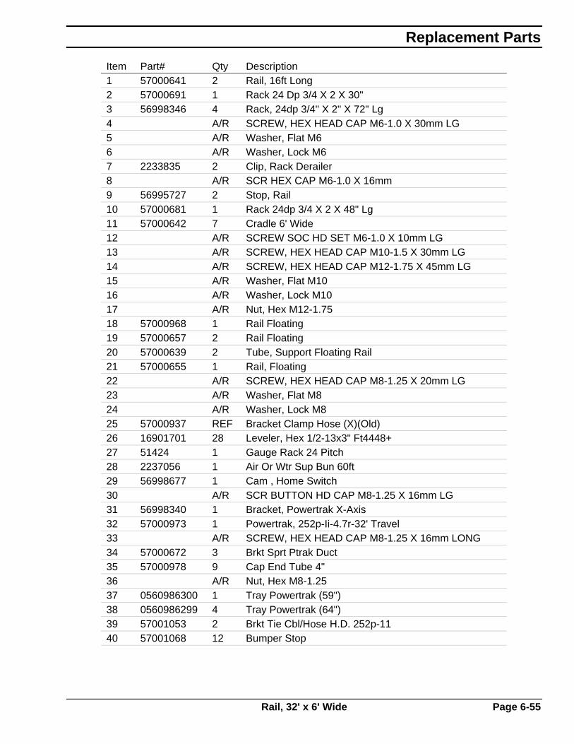
Item Part# Qty Description 1 57000641 2 Rail, 16ft Long 2 57000691 1 Rack 24 Dp 3/4 X 2 X 30" 3 56998346 4 Rack, 24dp 3/4" X 2" X 72" Lg 4 A/R SCREW, HEX HEAD CAP M6-1.0 X 30mm LG 5 A/R Washer, Flat M6 6 A/R Washer, Lock M6 7 2233835 2 Clip, Rack Derailer 8 A/R SCR HEX CAP M6-1.0 X 16mm 9 56995727 2 Stop, Rail 10 57000681 1 Rack 24dp 3/4 X 2 X 48" Lg 11 57000642 7 Cradle 6' Wide 12 A/R SCREW SOC HD SET M6-1.0 X 10mm LG 13 A/R SCREW, HEX HEAD CAP M10-1.5 X 30mm LG 14 A/R SCREW, HEX HEAD CAP M12-1.75 X 45mm LG 15 A/R Washer, Flat M10 16 A/R Washer, Lock M10 17 A/R Nut, Hex M12-1.75 18 57000968 1 Rail Floating 19 57000657 2 Rail Floating 20 57000639 2 Tube, Support Floating Rail 21 57000655 1 Rail, Floating 22 A/R SCREW, HEX HEAD CAP M8-1.25 X 20mm LG 23 A/R Washer, Flat M8 24 A/R Washer, Lock M8 25 57000937 REF Bracket Clamp Hose (X)(Old) 26 16901701 28 Leveler, Hex 1/2-13x3" Ft4448+ 27 51424 1 Gauge Rack 24 Pitch 28 2237056 1 Air Or Wtr Sup Bun 60ft 29 56998677 1 Cam , Home Switch 30 A/R SCR BUTTON HD CAP M8-1.25 X 16mm LG 31 56998340 1 Bracket, Powertrak X-Axis 32 57000973 1 Powertrak, 252p-Ii-4.7r-32' Travel 33 A/R SCREW, HEX HEAD CAP M8-1.25 X 16mm LONG 34 57000672 3 Brkt Sprt Ptrak Duct 35 57000978 9 Cap End Tube 4" 36 A/R Nut, Hex M8-1.25 37 0560986300 1 Tray Powertrak (59") 38 0560986299 4 Tray Powertrak (64") 39 57001053 2 Brkt Tie Cbl/Hose H.D. 252p-11 40 57001068 12 Bumper Stop
Replacement Parts
Rail, 32' x 6' Wide Page 6-55

6.28 Encoder Cable Assembly (Planetary Drives)
Reference Drawing: 57001403 (B)
Item Part # Qty Description
1 2237223 A/R Cable, 20 Ga., 4 Twisted Pairs, Shielded
2 57001404 1 Connector
3 93061804 A/R Wire, 18 Ga., Green
Available Assemblies:
Length Part Number
5' 57001405
10' 57001406
15' 57001407
20' 57001408
25' 57001409
30' 57001410
35' 57001411
40' 57002260
45' 57002261
50' 57002262
55' 57002263
60" 0560987405
PIECEMAKER 2
Page 6-56 Encoder Cable Assembly (Planetary Drives)

6.29 Vision LE CNC Control Replacement Parts
Assembly 0560935582 with connectors
Vision LE Control
Replacement Parts
Vision LE CNC Control Replacement Parts Page 6-57

X9
K3
K4
K5
K6
K7
K8
K9
K10
X10
D3
D1
D4
D2
D5
D23
D6
D24
D7
D25
D8
D26
D9
D27
D10
D28
X11
X12
K11
K12
K13
K14
K15
K16
K17
K18
D11
D29
D12
D13
D30
D31
D14
D15
D16
D17
D32
D33
D34
D35
D18
D36
R88
R87
R86
R85
R84
R83
R82
R81
R80
R79
R78
R77
R76
R75
R74
R73
V37
X19
V34V32V35
R24
R72
R33
V36
C101
V33
C100
C99
X13
R125
R124 L13
X97
L1
L12
R123
R98
X94
V54
X21 X20
V27
X86
C131
C104C107C9 C6
C66
C105
V24V25
C109C103
D38D37
R20
R7
X8R90 R108
R91
R92
R93
R94
R95
R105
R106
R89
R109
R110
R111
R112
R127
R128
R129
R107
R131 C114
R132
R133
R134
R135
R136
R137
R138
R130
C115
C116
C117
C118
C119
C120
C121
C113
C129
V38
X14
X15R145
R21
K2
K1
R31
D19
D41
R23
C25C
27
C134
C135
C133
C132
X7
V12
C28
C26
X5
R140R139R141
C7
C8
R61
R37
V26
C110
C111XT3
X4
J2
C136R39
R40
R41
R42
R43
R44
R45
R46
R47
R48
R49
R50
R51
R52
R53
R54
R55
R56
C77
C78
C79
C80
C81
C82
C83
C84
C85
C86
C87
C88
C89
C90
C91
C92
C93
C94
R119R118R117
R122R121R120
L15C22
C67
R115R114R113
C97C86C95
R96
R97
R64
R98
R65
R66
R100
R67
R101
R68
R102
R69
R103
R70
R104
R71
C68
C69
C70
C71
C72
C73
C74
C75
R63
R99
C76
C46
C45
C50
C49
C55
C57
D39
D20
L2
L3
L4
L5
L6
L7
R13
V39
V40
V41
V42
V43
V44
V45
V46
V47
C44R27R12R10R11R26C35C54C52R9C40R30R22R25R16R19
R36
C36R2R3
C47
C29
C48
R18
R15
R29
R14R17
R28
C37
C38
V14
R4R5C43
C30
R35
R1
R34
C22
C33C59
C60C34
C39 C31
V15
V13V16C32
R8
R32
C15 R58
V48V49
V50
C16
C17
C18 R59
C20 R60
C21
V51V52
V53
C124
V9
C123
V8
J3
J4
X1
X2
C12
C14
C19
X3
L8
F1
X6
D22
C13 R116
XT2
C3
C11
C10
V17
V21R143
R144
C65
R142
V22
C137
C138
D42
D43
V23R
38
X30 R57
C58
C42
C2
V7V3
C4
C56
Q1
C127
V55
V4
C41
C130
C128 C126
V18
V10
V28
C89
C125
C51
V2
V6
V1
V5
XP1XP2
C5
C106
V11
C102
C108 J1
J5
R126
R6
XT1
L14
C112
C64
C63
V20V19
C24
C23
C62
C61
L11
L10
X99
Vision LE PIO Board
PIECEMAKER 2
Page 6-58 Vision LE CNC Control Replacement Parts

Vision LE (ANC401) Replacement Parts List Esab part # Atas part # Description 0560935582 65.00.03041 Vision LE package (LE and connectors) ANC401
0560935209 65.00.03000 Vision LE (LE without connectors) ANC401 0560935538 65.00.03021 ANC 401 Front Panel 0560935537 65.00.03016 ANC 401 CPU Board 0560935535 65.00.03010 PIO401 Board 0560935540 65.00.03025 ANC 401-NG Power Supply 0560935539 65.00.02198 ANC 4x LCD Display 0560935567 65.00.03015 ANC 401 Flash Drive 16MB 0560935212 65.00.03019 ANC 401 Connector Set
0560936084 65.00.03039 Vision LE Floppy drive kit (AMF4-PM External Floppy drive)
0560936083 Floppy drv cable AMF4 KAB 2M 0560936080 65.00.03032 3.5 Floppy disk drive AMF4.PM Floppy drive 0560936081 65.00.03043 Vis LE Internal floppy cable assy. ANFL-ST Floppy 0560936082 65.00.03031 External Floppy mounting plate 0560936273 65.00.03070 ANC401-LFE Bd. Vision LE Teach Trace board 0560936271 65.00.03060 ANC401-Asiob1 board 0560936272 65.00.03049 ANC401-BDM6 kit Vision LE 6 Station macro key panel kit
0560935210 65.00.03040 ANC401-TT kit includes LFE Bd, AK5 camera, connector, softw.
0560936060 Vision LE to HL90 interface cable 0560935568 Vision LE APAP relay 0560935569 Vision LE Drive Allow relay 0560935585 Vision LE Literature package
Replacement Parts
Vision LE CNC Control Replacement Parts Page 6-59

6.30 Vision 1000 Control Console
Assembly 2236338 (A)
Item Part # Description
1 2236893 Front Panel
2 2238787 Enclosure Key
3 56995783 Joystick
4 56995789 Handle Bars
5 56995138 Complete Front Door Assembly
6 2236894 LCD Display Module
PIECEMAKER 2
Page 6-60 Vision 1000 Control Console

6.31 Vision 1000 Control Electronics
Item Part # Description
1 2236892 Digital I/O Board (DIO)
2 2238138 Process I/O Board (PIO)
3 2237974 Tracer Interface Board
5 2236898 System Floppy Disk Drive
6 2236342 Floppy Disk Drive
7 2238787 Enclosure Key
8 56995789 Handle Bars
9 2236895 Power Supply
10 RAM Module, included with item 11
11 57000393 Mother Board (C0.121.01)
56996850 Battery for DIO Board
Replacement Parts
Vision 1000 Control Electronics Page 6-61

PIECEMAKER 2
Page 6-62


Customer / Technical Support(843)-664-4405
(800) ESAB-123 (372-2123)
ESAB Welding and Cutting ProductsPO Box 100545 Ebenezer Rd
Florence, SC 29501-0545http://www.esab.com
http://www.esabcutting.com
ESAB Cutting Systems - Canada6010 Tomken Road
Mississauga, Ontario Canada L5T 1X9Phone: (905) 670-0220
Fax: (905) 670-4879
ESAB-Cutting Systems GmbHRobert-Bosch-Strasse 20
Postfach 1128D-61184 Karben 1
Phone 011-49-6039-400Fax 011-49-6039-403-02
http://www.esab.com
F 14 503 06/03 Printed in U.S.A.