Embed Size (px)
Citation preview

>~ r.:::;, (_)
---Lt_
e...:t --~--f~ ~ f<,~
--SOnex Reseaareh, Inc.*
300 CHINQUAPIN ROUND ROAD
ANNAPOLIS, MARYLAND 21401
(301) 263·8286
15 August 1983
NAHBE Ml51 RETROFIT EVALUATION
Final R~port To: Director, Power Pro~ram Material Science D:~ision Office of Naval Research Washington, D. C.
Contract No. N00014-81-M-0058
75 Pages, Unclassified, Distribution Unlimited
C. C. Faiila
*Formerly Heat Balanced Retrofits, Inc.
83 10 04 oo1~
f.

UnclassifiedSECURITY CLASSIFICATION OF THIS PAGE (I)Whn Data Eniered)
3aDf MSTRUCfOSREPORT DOCUMENTATION PAGE msroum COmmfowaI. REPORT NUMBER 2. GO AIO N
SONEX 838151 A -IAI334. TITLE (and uI.le) S. TYPE OF REPORT I PEIOD COVERED
MAYBE M151 Retrofit Evaluation Final - 1 July 81-30 June 83
6. PERFORMING ORG. REPORT NUMBER
1. AUTHOR(o) S. CONTRACT OR GRANT NuMEaW)
A. A. Pouring, C. C. Failla N00014-81-M-0058
6, PERFORMING ORGANIZATION NAME AND ADDRESS 10. PRGRAM ELEMENT PROJECT. TASK
AREA I WORK UNIT NUMIIERS
Sonex Research, Inc.300 Chinquapin Round RoadAnnapolis, MD 21401
II. CONTROLLING OFFICE NAME AND ADDRESS IS. REPORT DATE
Director, Power Program 15 August 1983Material Science Division, Office of Naval Res. IS. NUMUEROF PAGESArlinaton. VA 22217 75
14. MONITORING AGENCY NAME A ADDRESS(If diflonnt Im Conhtrllng Offtoe) Is. SECURITY CLASS. (of Ohio ropon~)
Unclassifiedlea. Deckl7 SIPIC ATION/ DOWNGRADING
ti. DISTRIBUTION STATEMENT (f IAta RoeiH)
Distribution unlimited
1T. DISTRIBUTION STATEMENT (of the .obract gtifed ln 8ie.& J N II dlffreta bm Repge)
Is. SUPPLEMENTARY NOTES
19. KEY WORDS (Coninwe an, mweve olde It nceeeoarnW mudl ftm& by Week r, nr)
Internal combustion enginesM151 - ), ton utility truck (Jeep)I ' Naval Academy Heat Balanced Engine (NAHBE)Combustion radicalsMulti-fuel engine, Engine emissions, Fuel economy
2G. ATPACT (Caflthua an revee side II m..e..e ad idmift by Up Seo be
: NAHBE (Naval Academy Heat Balanced Engine) state of the art technologywas applied to a standard military four cylinder M-151-1/4 Ton Utility Truck(Jeep) to demonstrate retrofitted versus standard engine performance inwaterbrake and chassis dynamometers as well as on the road.
Chassis dyno results showed a maximum possible retrofit improvement inmiles per gallon of 21.3% at 55 mph and 35.4% at 30 mph. Waterbrake dynoresults show higher improvements at low throttle settings indicating that
DD I FOM 14n oIIoN OF I Nov se is ossoLETe,JAN 1473 S/N 0 102 .L -o601 oqo.S/N~IRURT CLASIICAIO O.F TH-IN ~ m'v mo~ o PAGE (WAR 32=4114111
I Unclassified ,
SEcumITv CLASSIFICATO OF THIS PAIS fSNhf De OOe
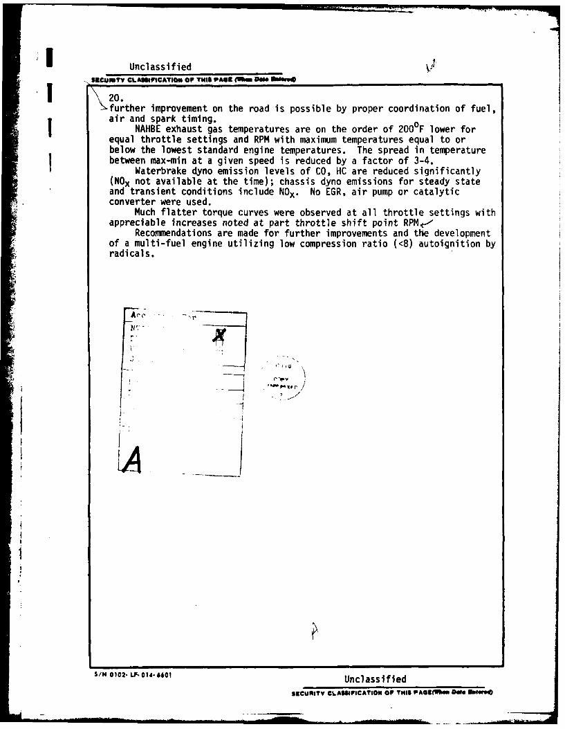
1 20..,further improvement on the road is possible by proper coordination of fuel,
! air and spark timing.| NAHBE exhaust gas temperatures are on the order of 2000F lower for
equal throttle settings and RPM with maximum temperatures equal to orbelow the lowest standard engine temperatures. The spread in temperature
I between max-min at a given speed is reduced by a factor of 3-4.Waterbrake dyno emission levels of CO, HC are reduced significantly
(NOx not available at the time); chassis dyno emissions for steady stateand transient conditions include NOx . No EGR, air pump or catalyticconverter were used.
Much flatter torque curves were observed at all throttle settings withappreciable increases noted at part throttle shift point RPM,--
Recommendations are made for further improvements and the developmentof a multi-fuel engine utilizing low compression ratio (<8) autoignition byradicals.
I I
S/N 0102 LF- .1. 61 Unclassified
SECURITY CLASSIFICATION OP THIS PASE(3l. A D 2*10840

I. ABSTRACT AND SUMMARY
NAHBE (Naval Academy Heat Balanced Engine) state of the art technology
was applied to a standard military four cylinder M-151-1/4 Ton Utility
Truck (Jeep) to demonstrate retrofitted versus standard engine performance
in waterbrake and chassis dynamometers as well as on the road.
Chassis dyno results showed a maximum possible retrofit improvement in
miles per gallon of 21.3% at 55 mph and 35.4% at 30 mph. Waterbrake dyno
results show higher improvements at low throttle settings indicating that
further improvement on the road is possible by proper coordination of fuel,
air and spark timing.
NAHBE exhaust gas temperatures are on the order of 200°F lower for equal
throttle settings and RPM with maximum temperatures equal to or below the
lowest standard engine temperatures. The spread in temperature between
max-min at a given speed is reduced by a factor of 3-4.
Waterbrake dyno emission levels of CO, HC are reduced significantly
(NOx not available at the time); chassis dyno emissions for steady state and
transient conditions include NOx . No EGR, air pump or catalytic converter
were used.
Much flatter torque curves were observed at all throttle settings with
appreciable increases noted at part throttle shift point RPM.
Recommendations are made for further improvements and the development of
a multi-fuel engine utilizing low compression ratio (<8) autoignition by
radicals.
I-1
I
Table of Contents
Page
I. ABSTRACT AND SUMMARY I-I
II. INTRODUCTION AND OBJECTIVES II-1
III. DESIGN PARAMETERS III-1
1) General Approach, Piston Ill-12) Intake Manifold III-23) Secondary Air Control 111-34) Carburetion 111-45) Spark Timing 111-46) Valve Timing 111-57) Summary of Final Design Parameters 111-5
IV. FABRICATION DETAILS IV-1
V. PERFORMANCE ANALYSIS V-1
1) Test Equipment and Facilities V-12) Waterbrake Dynamometer Tests of the NAHBE and
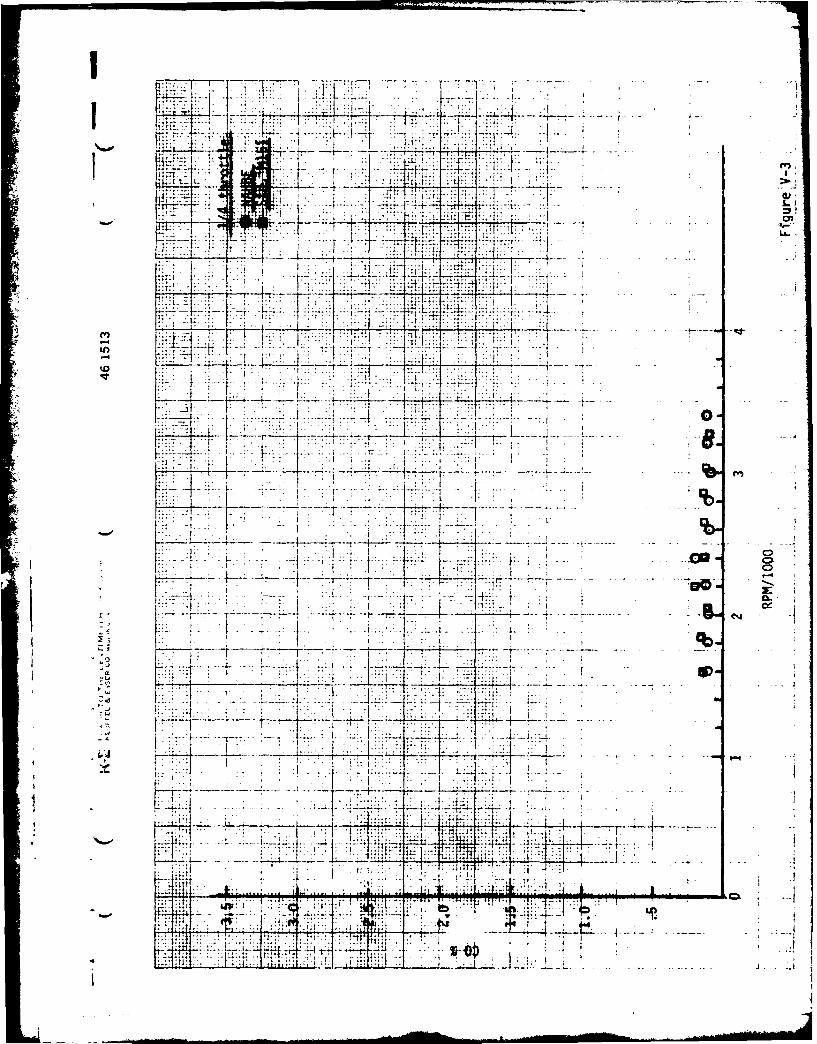
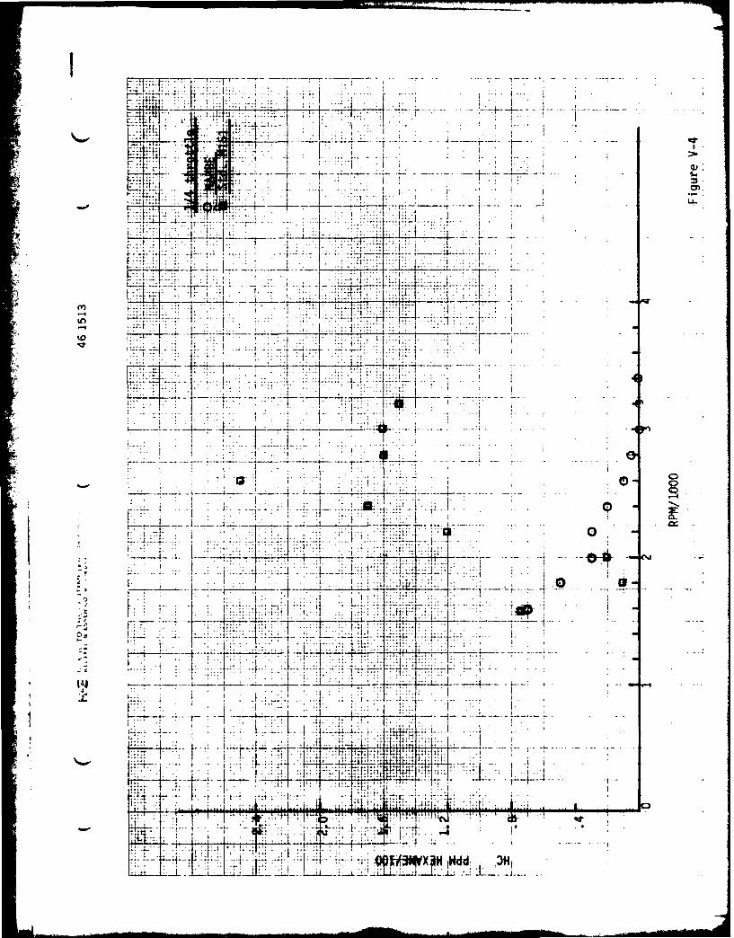
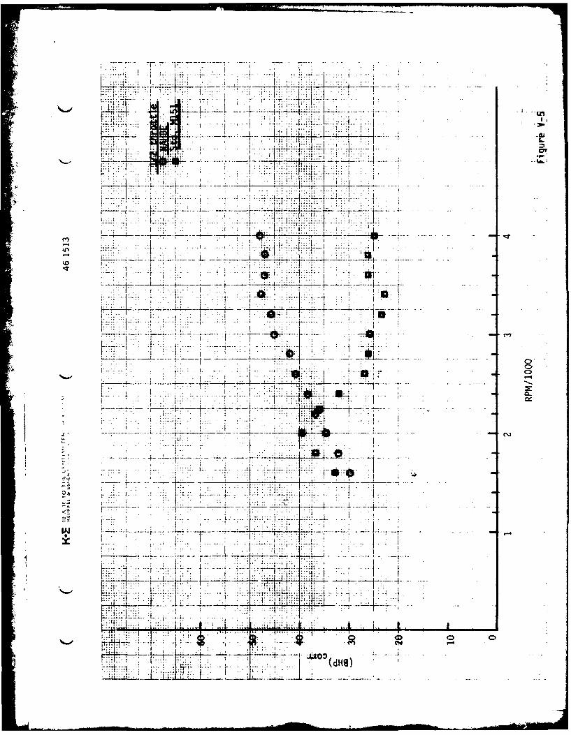
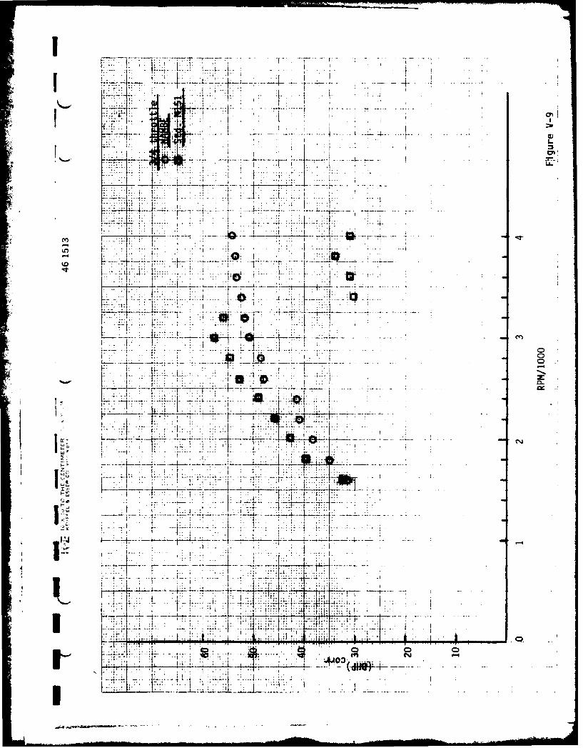
Standard Engine V-ia) Index of performance curves V-Ib) Test procedure V-3c) Test results V-3
3) Chassis Dynamometer Tests of NAHBE M-151 by Sonex V-64) Baseline and NAHBE Chassis Dynamometer and Road Tests
of the M-151 Vehicle by AM General V-9
VI. RESULTS AND CONCLUSIONS VI-1
VII. RECOMMENDATIONS VII-1
VIII. REFERENCES VIII-1
IX. APPENDIX IX-1
....
I , w i i l ,. .... i ' -... .

1
II. INTRODUCTION AND OBJECTIVES
It was proposed originally in an unsolicited proposal to ONR dated
1 May 1981 that the state of the art of the technology described in
Reference 1 be applied to retrofitting an M-151-1/4 Ton Utility Truck
(Jeep). Thus, a brief review of recent research reflecting the state of
the art is presented here as well as an update on this company.
From the point of view of both theory and experiment in single
cylinder engines, References 1-4 reflect the latest advances. Reference 1
summarizes the influence of geometries involved in piston design, secondary
air manifolding and gives, as well, a comparison of a standard engine
using the same technique of manifolding.
Since we are dealing with a new technology a quick review of the
associated terminology is in order (from Reference 1). Two basic
differences are involved in this engine concept. First, a cap is used
on top of the piston to create a divided chamber in the cylinder. The
upper chamber, VA Figure II-1, is the combustion chamber, while the lower
chamber, VB9 is the "balancing" chamber or air reservoir. The ratio VB/VA
is defined as eta, the balancing ratio. The total clearance volume
VC = VA + VB is used in computing compression ratio. A gap exists between
the cap and the cylinder wall.
4 The objective is to create an axially stratified charge in the cylinder,
with a lean mixture at the bottom, rich at the top, such that on compression
a very lean (ideally air only) charge is forced into the balancing volume; a
rich composition remaining in the combustion chamber. It is shown in
Reference 4 how compression waves formed by the combustion front penetrate
Lai-i

r VA VA
TDC e W
VA VOLUME ABOVE CAP (COMUSTION CHAMBER) 0 TDC
Ve VOLUME IMELOW CAP (I§AANCIN CHAUGER)
VC VA - Vs. CLEARANCE VOLUME
VA DISPSACENT
r(VA - Vol /Nc, COUMNU4# RATIO
General Terminology for Heat Balanced Engine
Figure II-1
the balancing chamber, compress the medium within, and pump mass from the
balancing chamber to the combustion chamber. It is this pumping action
which prolongs the combustion process allowing control over both pressure
and temperature in the cylinder.
In addition to the time dependent combustion inherent in this technology,
internal heat regeneration is known to play an important role in improving
performance of the engine. It is shown in Reference 2 that at low compression
(r - 5-6), compression ignition operation with various fuels is possible.
(6)The energy for ignition must come by heat transfer or radicals (
. Reference
3 is the first step in explaining the role of regeneration in this engine;
under study at present is the effect of regeneration in a dual or combined
cycle and the influence of precombustion radicals.
The second difference involved here is associated with the method of
attaining axial stratification or separation of the charge. Reference 1
11-2
I explores several modes of attaining this with carburetted engines. The
means selected of introducing secondary air into the intake manifold
requires a feeder tube welded into the intake manifold allowing air alone
into the region of each intake valve. Since the intake valve is open
only a fraction of the time, a charge of air accumulates in the intake
Imanifold to be followed by a richer than "normal" charge from the carburetor.Reference 1 shows how engine performance is affected by variation only of
this secondary air parameter in figures 14-18.
Attaining control of secondary air in a vehicle is made possible by
the technology described in Reference 5. A feedback control system
regulates admission of secondary air by examining engine output continuously.
Secondary air is thus controlled by an electronically controlled feedback
air throttle.
The vehicle described in this report contains modified pistons, modified
intake manifold, and a secondary air control system; minor modifications in
carburetion were also made.
HBR was founded to develop into practical form the art described thus
far. Because of default of the original financial backer, more than six
months were lost in completing the work described here. However, the
company was reorganized, renamed to Heat Balanced Research, and refinanced.
The company now has a machine shop, instrumented waterbrake dynamometer lab
and instrumented chassis dynamometer. It holds an exclusive license on the
secondary air control patents for use in HBR technology, has an agreement
with Gulf 011 with regard to multifuel engine testing, and is currently
negotiating with Eaton Corp. for manufacture of components. An agreement
II-3
*now Sonex Research
I

I with AM General provided the vehicle in the report as well as testing
+ Ibefore and after the modifications by Sonex.
Objectives:
To apply the technology outlined above to an M-151-1/4 Ton Utility
Truck (Jeep) such that:
1) a pre-production prototype is produced which will improve overall
fuel economy.
2) emissions are lowered to the point of meeting 1980 EPA standards
with no EGR, no exhaust air pump and no catalytic converter.
3) the engine is insensitive to Octane number.
4) the design is retrofitable.
1
11-
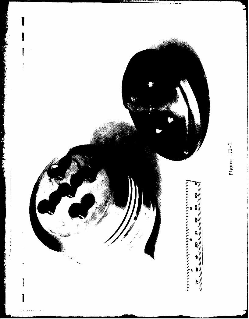
III. DESIGN PARAMETERS
1) General Approach, Piston
Two engines were converted to the heat balanced design; one a
scrap engine completely rebuilt, and the second taken from the M-151
provided by AMG for this test. The purpose of using the scrap engine was
to test design parameters, that is compression ratio (r) and balancing
ratio (a). According to Reference 1 optimum results should be obtained
at r 8 and a 0.8.
The first M-151 design gave r 7.5 with the difference attributed
to cumulative measurement error. Since 0.100 inches was already milled
from the head, it was impractical to reduce the head volume further. A
decision was made to reduce the balancing volume to compensate giving the
final result of rZ 8.0 and B 0.5. The resulting composite piston is
shown in Figure Ill-1.
II.,
III
r-4
I-i
'I
bD
Z7'
* a
I
I

2) Intake Manifold
Reference 2 gives some details on the percentage of primary versus
secondary air used at best power with several fuels and hence the design
proportions on the intake manifold. From Reference 1, the percentage
secondary air is seen to increase at best economy since best power is at
an air/fuel (A/F) ratio A/F 16, while best economy is at A/F 20. Thus,
at best power the primary/secondary (P/S) air flows should be - 50/50 and
at best economy P/S 40/60.
Intake manifolds were fabricated with these ratios, but output
equal to the standard engine could not be obtained. It appeared that with
the single barrel side-draft carburetor full advantage of the secondary air
could not be taken as the throttle opening approached W.O.T.. The pressure
drop through the secondary throttle was too large compared with the primary;
this was confirmed by flow bench tests. This can be avoided by using a two
barrel carburetor with dual port manifolds, a current practice by Sonex
(BSFC = 0.378 lbs/BHP-HR has been attained in such a design).
As a compromise, the W.O.T. power was sacrificed to obtain good part
throttle results and the secondary air size reduced to accommodate the
part throttle range. The resulting manifold is shown in Figure 111-2.
111-2

Sonex Research, Inc.300 CHINQUAPIN ROUND ROAD
ANNAPOLIS, MARYLAND 21401
(301) 263-8286

1
4
'-II-~4'-4
4,54
bOfl-
4
rz-.
3) Secondary Air Control
Using the adaptive lean limit control concept described in Reference
5, continual adjustment of the secondary air flow is possible, except, in
this engine, for conditions approaching W.O.T.. A digital stepper motor,
driven by appropriate circuitry, continually adjusts an air throttle valve
at the entrance to the manifold secondary to give an optimal air fuel ratio.
Several adjustments are possible to tune the speed of response, cut-off
speed and A/F ratio. A view of the air throttle and electronics is seen
in Figure 111-3.
Test data are presented using both manual and electronic secondary
air control. Torsional vibration feedback from the waterbrake dyno interferred
with proper sensing of acceleration and deceleration of the engine crankshaft
which is vital to FIDCO operation. This problem was not experienced on the
chassis dyno.
4) Carburetor
Several variations in carburetor design were investigated. In an
attempt to richen the low RPM operation, a boost venturi was added to the
stock Facit-Zenith carburetor. Data in the waterbrake dyno are for the
carburetor with boost venturi. Chassis dyno tests were conducted with and
without boost venturi. Various combinations of idle jet tube, power valve
tube and spring, and main fuel jet were investigated. The final configura-
tion used a standard idle tube, no boost venturi, #32 main fuel jet,
standard power valve-accelerator pump tube, standard power valve spring with
washers to actuate at 4-5 inches of Hg.
111-3

ISince the standard carburetor has no mechanical accelerator pump
cold starting is often difficult. An aircraft engine primer was added to
the carburetor by drilling out an existing brass plug and tapping for a
1/8" pipe nipple. Fuel supply was taken by adding a tee to the fuel reclrcu-
lation fitting. The primer, located on the dash board, is manually actuated
by the driver and is generally required only on the first start of the day.
5) Spark Timing
The number of variables involved in this engine concept is greater
than for the standard engine making determination of the minimum advance for
best torque difficult. An attempt was made, however, to optimize the spark
electronically in the waterbrake dyno using a TRAC II, J & S Electronics,
Garden Grove, California. These results together with variations possible
with the existing system were considered in determining the best spark
advance profile. The final settings were determined using stock springs
and weights and a static advance of 170 BTC.
6) Valve Timing
Valve overlap affects the intake manifold fuel/air composition.
The objective here is to attain a separated charge or axially stratified
charge first in the manifold, then in the cylinder. To lessen the influence
of valve overlap on the intake manifold tests were conducted on optimum
valve clearances with a stock camshaft. The influence was quite clear and
final clearances (hot) adopted are given below.
1
111-4
II
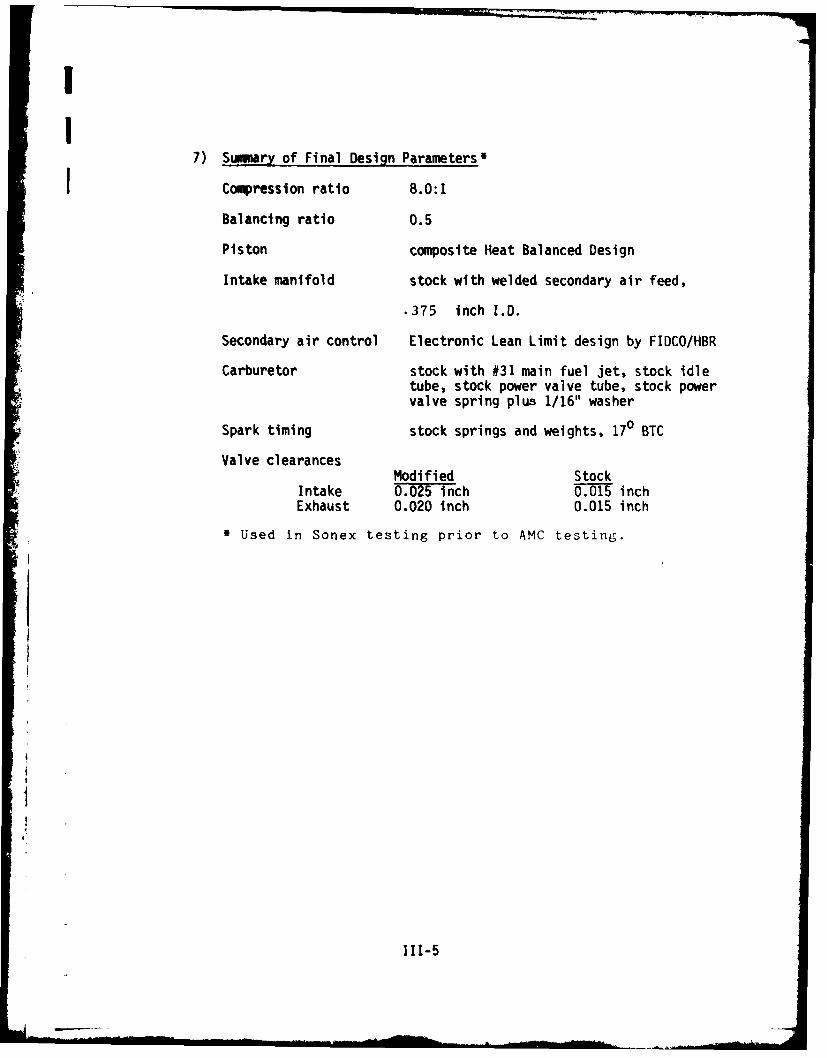
7) Sumary of Final Design Parameters'
- Compression ratio 8.0:1
Balancing ratio 0.5
Piston composite Heat Balanced Design
Intake manifold stock with welded secondary air feed,
.375 inch I.D.
Secondary air control Electronic Lean Limit design by FIDCO/HBR
Carburetor stock with #31 main fuel jet, stock idletube, stock power valve tube, stock powervalve spring plus 1/16" washer
Spark timing stock springs and weights, 170 BTC
Valve clearancesModified Stock
Intake 0.025 inch 0.015 inchExhaust 0.020 inch 0.015 inch
* Used in Sonex testing prior to AMC testing.
1
111-5
:I
IV. FABRICATION DETAILS
Techniques developed during the past year allow scaling of optimized
piston design results from one engine to another. At present, however,
finite element programs for thermal and stress analysis are not available.
In their absence simple electrical analogs are used to determine approximate
temperature distributions. Such techniques are not sufficient to design a
piston entirely of aluminum that will last a reasonable time under operating
conditions. Thus, the composite piston shown in Figure III-1 is used with a
steel cap attached by machine screws to a forged aluminum base made to our
specifications. A similar design under test has recently passed 12,000
miles on the road with no adverse affects.
All machining on the piston base and caps was done in the HBR machine
shop. Final assembly of the engine and the final shave on the head (to a
depth of 0.100") was done by experienced engine builders - Precision Engine
Machine Co., Hyattsville, Maryland. All piston-rod assemblies were taken
to the lightest assembly weight.
Unfortunately, the engine as received from AMG was bored to maximum
tolerances. Special piston rings had to be used to satisfy maximum end gap
tolerances with the pistons used. Since fitted rings were not available in
the width normally used in the M-151, a narrower width was used with spacers.
This fabrication compromise resulted in a long break-in time, and most of
the waterbrake dyno testing was done with the engine not fully broken in as
compression test readings continued to rise up to the time of chassis dyno
testing. This feature may also shorten piston life and reduce the effective
compression ratio.
IV-1

I Little machining was required other than drilling in modifying the
Intake manifold. Aluminum tubes were welded into the aluminum manifold
with threads at the upper end to accept standard copper tubing fitting.
The rest of the secondary air intake was made from copper fittings soldered
together.
I
IV-2
V. PERFORMANCE ANALYSIS
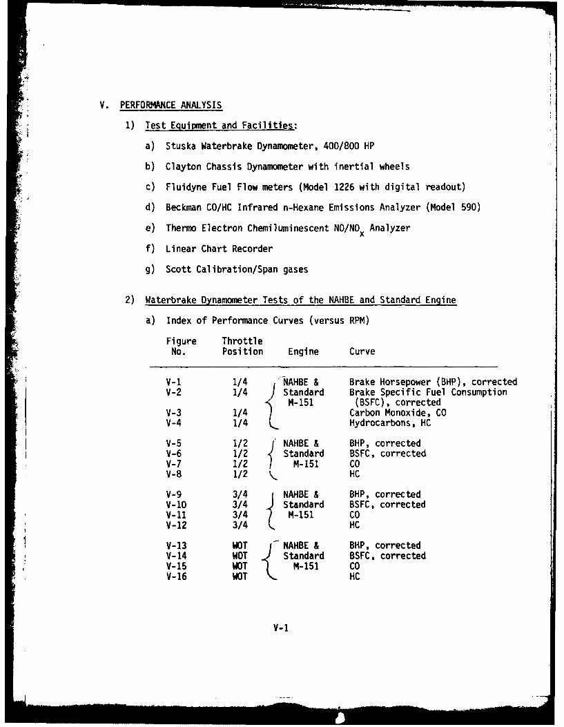
1) Test Equipment and Facilities:
a) Stuska Waterbrake Dynamometer, 400/800 HP
b) Clayton Chassis Dynamometer with inertial wheels
c) Fluidyne Fuel Flow meters (Model 1226 with digital readout)
d) Beckman CO/HC Infrared n-Hexane Emissions Analyzer (Model 590)
e) Thermo Electron Chemiluminescent NO/NOx Analyzer
f) Linear Chart Recorder
g) Scott Calibration/Span gases
2) Waterbrake Dynamometer Tests of the NAHBE and Standard Engine
a) Index of Performance Curves (versus RPM)
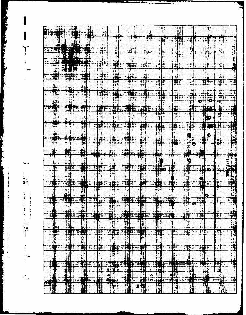
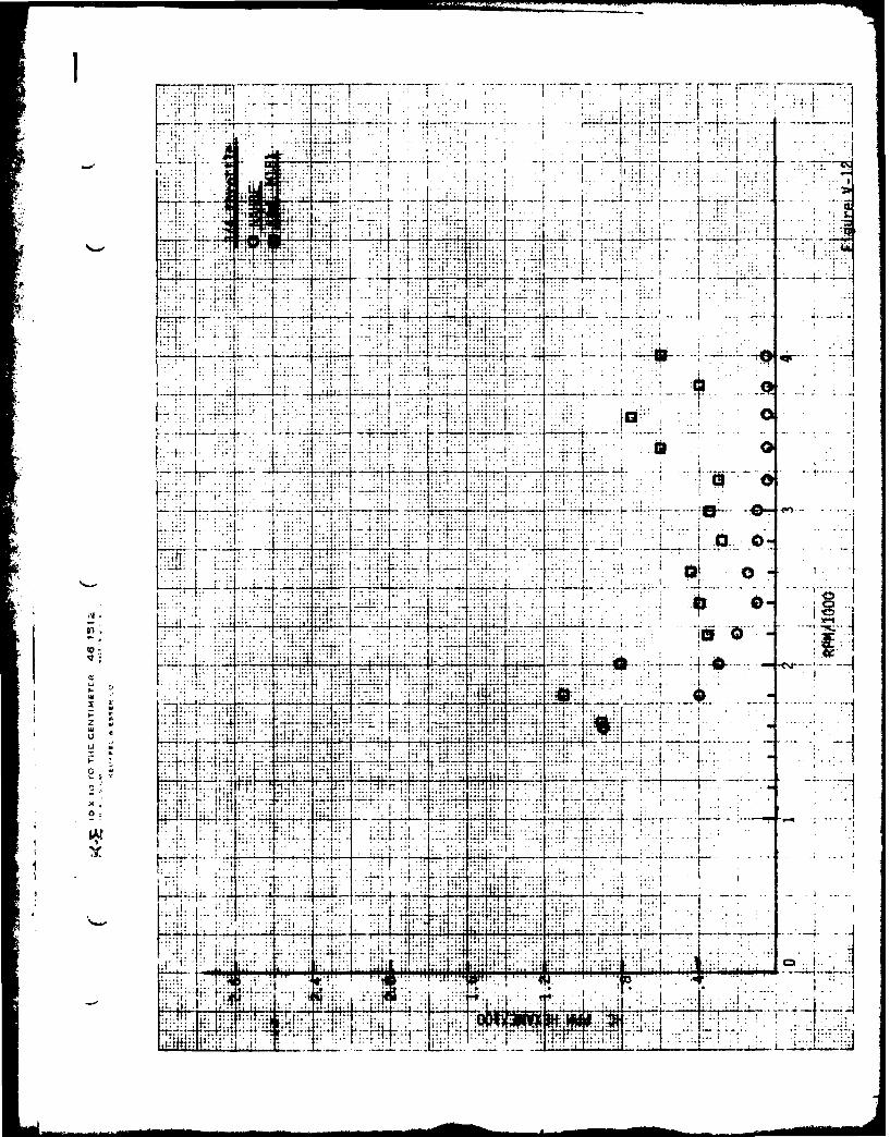
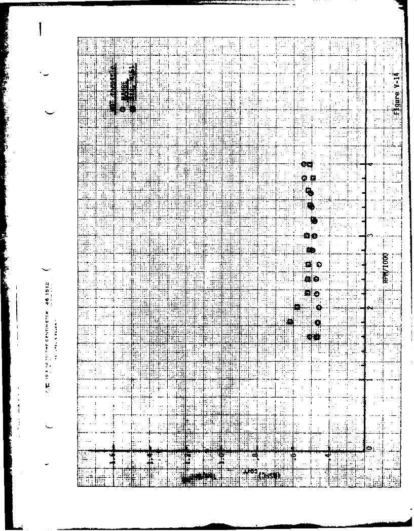
Figure ThrottleNo. Position Engine Curve
V-1 1/4 NAHBE & Brake Horsepower (BHP), correctedV-2 1/4 Standard Brake Specific Fuel Consumption
M-151 (BSFC), correctedV-3 1/4 Carbon Monoxide, COV-4 1/4 Hydrocarbons, HC
V-5 1/2 NAHBE & BHP, correctedV-6 1/2 Standard BSFC, correctedV-7 1/2 M-151 COV-8 1/2 . HC
V-9 3/4 NAHBE & BHP, correctedV-1O 3/4 Standard BSFC, correctedV-li 3/4 M-151 COV-12 3/4 HC
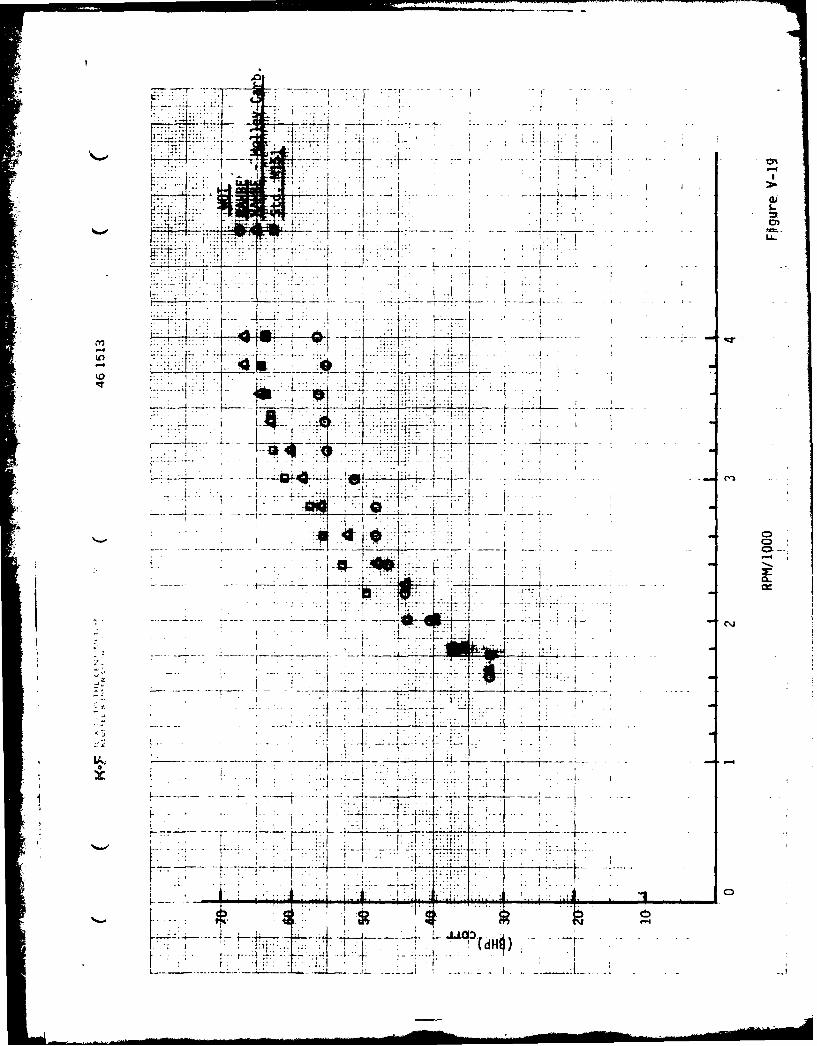
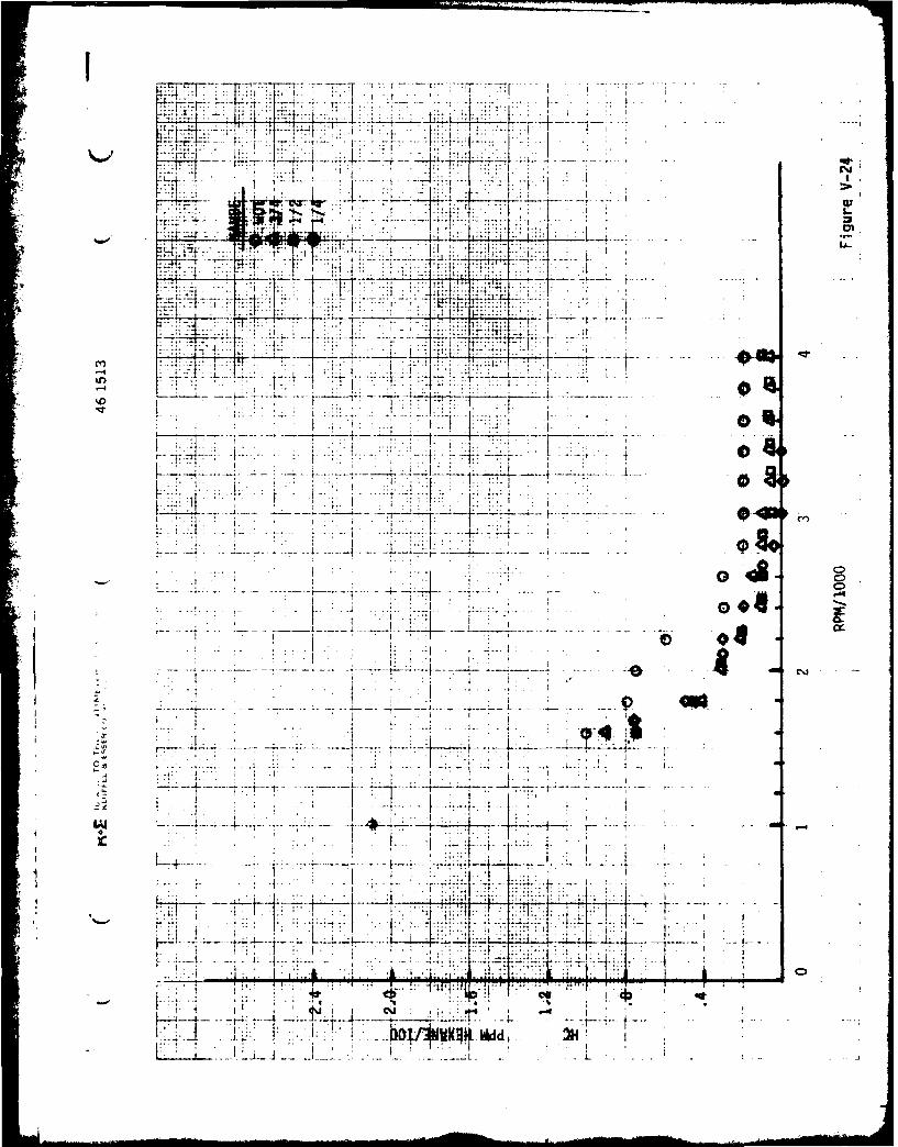
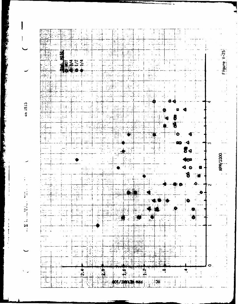
V-13 WOT NAHBE & BHP, correctedV-14 WOT 2 Standard BSFC, correctedV-15 WOT M-151 COV-16 WOT HC
V-1

Figure ThrottleNo. Position Engine Curve
V-17 1/4, 1/2, NAfIBE BHP, corrected3/4, WOT
V-18 1/4, 1/2, Standard BHP, corrected3/4, WOT M-151
V-19 WOT NAHBE, BHP, correctedStd. M-151.NAHBE-Hol leyCarburetor
AV-20 1/4, 1/2, NAHBE BSFC, corrected3/4, WOT
V-21 1/4, 1/2, Standard BSFC, correcteda/4, WOT M-151
V-22 1/4, 1/2, NAHBE CO3/4, WOT
V-23 1/4, 1/2, Standard CO3/4, WOT M-151
V-24 1/4, 1/2, NAHBE HC3/4, WOT
V-25 1/4, 1/2, Standard HC3/4, WOT M-151
V-26 1/4, 1/2, NAHBE Exhaust Gas Temperature (EGT)3/4, WOT
V-27 1/4, 1/2, Standard EGT3/4, WOT M-151
V-28 1/4 NAHBE, Torque()Manual,Auto,Std. M-151
V-29 1/2 NAHBE,Manual,Std. M-151
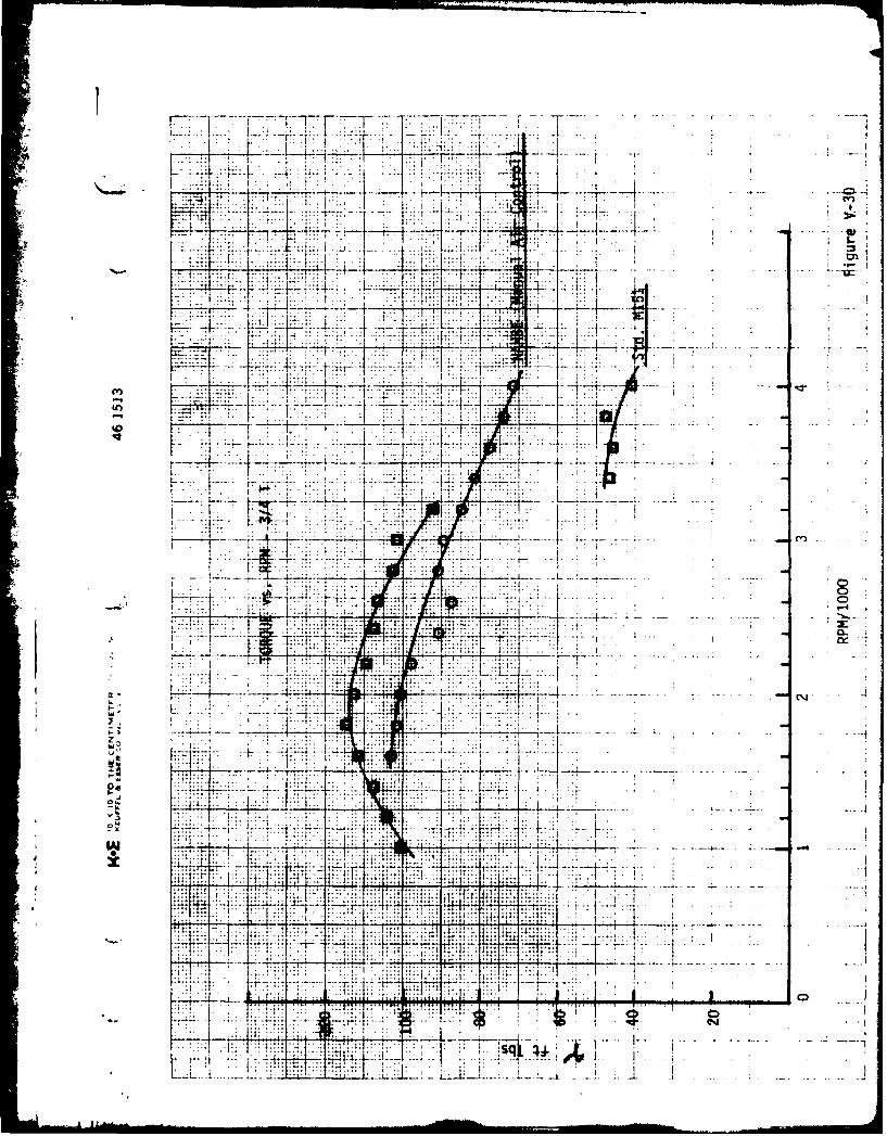
V-30 3/4 NAHBE,Manual,Std. M-151
V-31 WOT NAHBE-best,NAHBE,Std. M-151
V-2

.10.
KLA-
L
CD
I7-: riI I--
i A! 0" CD
CD
LLL

iji Li i
.. . .. -- 1 0--- . -
I a1
~L~1 h~I 4 Y7T
LL
as.
7..'
7 7 -- ----
7 -- -- 4~~1~
if -a
'7 -1 .. > -t4
* .
.... -wi------i--D'Tvr7i4
d
7-
-N~77 7 7K 4
p7 7q m 7-T
F4. 77F> 7'
00
*
0
K-* I ~ i.I 3**j
-I-' .
J-, -
w a
I m z-T1 ~. -
_
led;. . ; . a + ! . . . .
_ILL -t--> IDH
V T - 7
L :j
*
Ll -
4 17
1- p 1--CD
K ' L
~~~
HLK< l

7t-
17~
a o
t tto
~ ~~Md L--------.~-1---4-----

tl-
I rr
p L
177-17 -'--4Ht--~.
1.03

4 47
'~-7!-
77...
- I -
7 7
771 U-
p~F 1 i A . coI~ ffi_
0
I.-
p1-71
E 7
jL .
.l ' .... .1 z 7
v L74. F ~t * T7 T7,I-t-.

-7-44
--
4- + 7j I
U,7
-4 L a 0
t t
it K
Ij, IN. V
.. .. ..... .
Lid-
hah
IFj -141
a.. I
:I::
4:
4- I177- 7I77-i 74
tmI
i' -7 . 1 .T
:774yE7T>"7 7
rl ~ ~ ~ .. .....- .- ..-
w .
Ko

17.
!tt7r-h
1.L
.. ... ....
4 II
-j.. ... IM~.
t r!
... .. ...
.. . ... ..
-171- -1.1..
tit t4~~.i~iii1.i iir; , _ 1
'I _i 4 LI
IW4 'im
.ji:
iti
Ift.
ID
I-.1:; it;,

I IT
IIt
j.- 42 r
~ .~L.4-*. ... .... ..
TI ii
- 4
-, tl~
.15 4
II *
r-r- 1 -~ -.-

iiiix
...............................................................
7t:72
T!: ::42I'7 .2 Th: :i ~
f-.7771 7-:4
-l~ E: N

I I
-18-4
Ar I 00* LJ
L i--r--- "--Hi----
I t. i.
-7-I~1 -j-'~ ~ *J*-*lj
-A40

7- ii7
IFI,
- 7
LM 17f-I
I -o
0 iCD
Lw.0
-1
j. 7 U-C,

77V77:W 7 7T 7.W71 ]~7...
I Co
- 4-.. 1.-
-H--- - -~--.- --- 4-
10 C
4 t
'404

II . .
i.t
*d I v-qI

~I74
-f ......-..-
O r
- 48
1 1 1 CD
111N7
-1 1 . -~9 .0-

fTTT~TF7 17 :WI--
... W-44
...- 7 -:',....
7 1 -
Iii
~ L ~ilHI A~AII
I. A l 1~ .:'.
.7- .-T .
j-4-
-1 0
0 c
Ii...... A t
1 -4
.g Add-
l -E f - -. - 21Ip.J ' T!7
i !I4. T-
F j~ ... .. ....
LOr7T--
L . -V
---. -4-44
t~At
.. . . . ..
LAIAM
- -.-. . --- fL

k 41,
t-w . ..... .,
-Ito
-..........
1 4Z.4.4r
.1 4.
KI

T IT-
L O
:-7
I --
4- till C
a .'...- . .. .
-7-t 77" -
77.i......
L __T: , *L-

1 F.
F 7
-7-
I-7
1 .. ....
.. .... .. ..
IT,,ITI
t4'
IT ... ... ..
I--4.1 .T -ij- - -- C" -
0i-. H
.4 -i
itI ~iK
:rIt
T.
w

7,: 7.. : ..
17. w.1
-04
:77 .......
751
.. .... ...
... 1.......... At;
77 FF~W~:j~)..7-
w~ m- -7I
14-
I~~*., 7II
.... .... . ..... ~
[ L
IV .11 j ...1 717

717 L - - 7-
v t .. ....-.
i4 4
1' I Al
7' 7" I -:W. ... .... ---K ~' Aj I. 7-K~~~ *17.:uI T

~ K : IV.b--
-.
44~.
r.
1 T . . .
777 ~ 4 7
To
I-.-
7 7
zLI
f:f
.1k1.1i. A!
f q. .......

1,7
. . ... .
-4A
71 .77
i i K
** 9_-9
..... .~ . ..
7 F-
K-~ ~ .... ... I
447 7!. --
-4--L--1----
-44
-7-1

-~~ -- 4 .
-7::. F, I 77' 77.
F ':.. ..K.... ..A, -j7 t -
:177 --- ----- - I
- TY7
:J -----~ ~ - -- ~ - - -
K4.4E-
-,-
77.:7.-
H ......... ..[~~~H 7 ~ j4 ++4tjzk
7!'-I--
r-7 -. -
~~--Vr'L A ~ - - H

I7T7T T-' Ili .r
7-.~
44; I: H i10-
..
44
.7 .
77, :41 ..... ... ..
-- 47~ :I[ +
aa
t 0 Tz
l-t t .... .. :. ...
i 7- .j7J. ~

7:::
.. .. .... .
-4: 1 V;: :t
1I L : :4
0 4 ~ jj .. .
.77~7:t~ -~ ilL4.
-T--.4- o
T 1-
6 1.
it j--
7--- -4~ -.1. -'4i*dv XA'Hj* T
- ~ -7
- 4,
K - .i..j-1.II 1
:w 7~u a.
b) Test Procedure
The engine in each case was warmed up and test runs initiated
when oil and water temperatures were stable. At fixed throttle the
maximum load was applied that the engine would hold some minimum RPM. The
load was then reduced at fixed throttle in 200 RPM increments. Exhaust
gas temperature was taken at the exhaust manifold discharge. Emission
samples were taken with the probe located approximately 5 feet downstream
of exhaust manifold. The NOx meter was not available at the time of these
tests.
For the sake of easy comparison individual performance curves at
1/4 throttle through WOT for the NAHBE and standard M-151 engine are plotted
in Figure V-1 through V-16; summary curves are given in Figures V-17
through V-27. With the manually operated dynamometer available, testing
at 1/4, 1/2, 3/4, and WOT was the most reliable and repeating method.
Standard SAE correction factors were used in calculating results.
c) Test Results
Comparing the horsepower output at 1/4 and 1/2 throttle, the
NAHBE output exceed the standard M-151 output beyond the point where the
standard curves break off. This also shows up in the later torque curves.
At 3/4 and WOT the standard M-151 engine output exceeds the NAHBE for the
reasons stated in the section on manifolding and carburetion. To show how
output could be increased in the same engine a downdraft Holley two barrel
carburetor was adapted to the intake manifold with the result shown in
Figure V-19. Maximum output at maximum RPM exceeded the standard M-151
V-3

I
with an intake manifold that did not favor high engine output (secondary
air flow was too low). The torque curves at WOT also reflect this in
Figure V-31.
Part throttle torque curves of Figure V-28 show manual and auto-
matic (FIDCO) secondary air control. As was pointed out earlier, torsional
vibrations from the waterbrake impeller disturbed the electronic control
so all waterbrake results are for manually adjusted secondary air. In the
chassis dyno these results are inverted with automatic air control results
exceeding manual results. Again at 1/4 and 1/2 throttle, at the shift
point of about 3000 RPM, NAHBE torque exceeds the standard M-151;and even
at 3/4 throttle there is no break to a lower torque at higher RPM.
Although peak torque of the standard M-151 exceeded the NAHBE, it is
possible there is less difference now that the engine is broken in; a
gain of 10-15 psi in compression readings was experienced later in the
chassis dynamometer testing.
Brake specific fuel consumption (BSFC) at 1/4 throttle is signifi-
cantly lower in the NAHBE than the standard M-151. Comparing the average
between the two, the decrease in average BSFC at 1/4 throttle is 44%.
The imrovement decreases, as expected with the design compromises made,
with increasing throttle setting. The improvement decreases to 5.5% at
iOT with "standard" carburetion and 9.3% using the Holley carburetor. It
is significant to recall these results when comparing later results in the
chassis dyno at 30 and 55 mph.
There is no significant difference in CO at 1/4 throttle; at 1/2
throttle a wide excursion from .1% to 7.0% occurs in this standard engine
V-4

under high load with low manifold vacuum. At 3/4 throttle, low load,
high RPM conditions, NAHBE CO increases from 0.1% for the standard engine
to 0.35%; at high load, low RPM, NAHBE CO is 0.5% while the standard
engine is 1%. Below 3400 RPM all NAHBE CO readings are significantly
lower. Again because of the design compromise at high throttle openings,
the NAHBE CO readings are above those for the standard engine, Figure V-15.
I Unburned hydrocarbons (HC) at 1/4 throttle are considerably lower
in the modified engine at all but two RPM readings; the same can be said
at 1/2 throttle. At 3/4 throttle NAHBE hydrocarbons are lower at RPM
other than the one reading where they are equal. At WOT, even though
fuel-air ratios are not optimum, the modified engine HC are lower over
most of the load range, Figure V-16.
Exhaust gas temperature (EGT) for the two engines is compared
in Figures V-26 and 27 at throttle settings from 1/4 to WOT. All NAHBE
EGT's are lower than for the standard engine with the highest modified
engine readings corresponding to the lowest standard engine readings.
The average spread in readings at a given RPM is significantly lower for
the NAHBE with a typical spread of 50°F while the typical standard M-151
spread is 1500F.
This difference in exhaust temperatures is to be expected (Reference
1). It gives rise to an unexpected effect on the road, however. One sees
the exhaust manifold and exhaust pipe flow "cherry red" back to the muffler
in chassis dyno tests in the standard engine; thus, one has a very effective
thermal reactor to reduce CO and HC emissions. This is not the case with
the modified engine. It can be shown that a decrease in exhaust gas
V-5
temperature can reduce the exhaust gas reaLtion rate by a factor of
10.
3) Chassis Dynamometer Tests of NAHBE-M-151 by Sonex
A Clayton inertial wheel chassis dynamometer (installed at Sonex's
facilities) was used to test the retrofitted M-151 Jeep under steady state
and transient conditions. Fuel flow was measured with a Fluidyne Model
1226 meter with digital readout. Carbon monoxide (CO) and hydrocarbons (HC)
were measured on a Beckman Model 590 Infrared n-Hexane Analyzer and NOx was
measured on a Thermo Electron Chemiluminescent Analyzer; all were recorded
on a Linear Chart Recorder. Instrumentation was calibrated at the beginning
of each run and span gas (frm Scott Labs) checks were made periodically.
Because of some uncertainty in the chassis dyno calibration, road load was
set to match actual manifold vacuum observed at 50 mph on the road.
Testing
All steady state testing was conducted at stable engine coolant
temperatures with speed maintained constant by a driver. Data were recorded
for a three-minute period. The results presented here are the best
compromise of manifolding, secondary air control (FIDCO), carburetor jetting,
valve clearance, and spark timing. All these parameters were optimized in
the waterbrake dyno but adjusted further according to the chassis dyno test
results.
a) Steady State Test Results (Regular Gasoline)
Miles per gallon
Figure V-32 compares the modified M-151 as delivered by Sonex
to AM General with the base line data at 30 and 55 mph provided by AMG.
V-6
1
Our chassis data is based on observed or uncorrected results while AMG
data has been corrected to standard conditions. For the atmospheric
conditions at the time, correction to standard conditions would further
increase the NAHBE miles per gallon. Since it is uncertain that our dyno
loads are equivalent to the AMIG loads, the data were left uncorrected.
The improvement in mpg at 30 mph is 27.5% and 58.9% at 55 mph
as seen in Figure V-33. According to the part throttle results obtained in
the waterbrake dyno, further chassis dyno improvement should be possible at
the lower speeds since the average improvement at 1/4 throttle was 44%.
Emissions
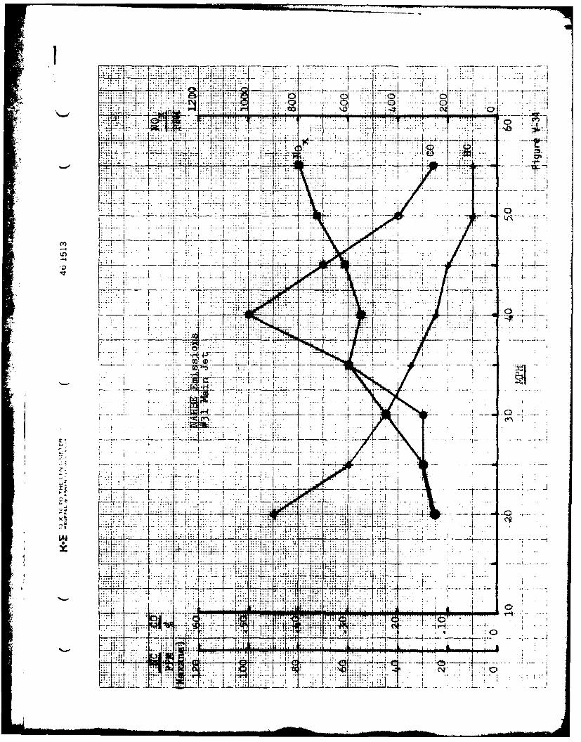
Steady state emissions are given for the final configuration
in Figure V-34. Comparable emissions for the standard M-151 are not
available, however, some additional tests for mileage and emission are
compared by AMG in the next section.
The excursion for CO from the .1% level at 30 mph to .5% at
40 mph and returning to the .1% level at 55 mph is due to a mismatch in
secondary air control. The manifold vacuum shows a similar excursion
increasing to 14 in. Hg at 40 mph from 13 in. Hg at 30 mph, then decreasing
to 11 in. Hg at 50 mph. The FIDCO air controller drove nearly closed at
40 mph thus limiting the flow of secondary air. With proper tuning of the
unit it should be possible to run all steady state conditions from 20 to
55 mph at 0.10-0.20% CO.
Transient test results - acceleration and deceleration
The test results in the waterbrake dyno showed consistently
smooth curves with no marked departures at any throttle settings. However,
-..7
when the engine was placed in the vehicle and given base line CVS-3 tests
in a chassis dyno at Scott Labs prior to the installation of the HBR chassis
dyno, recordings of transient operation showed high CO under acceleration
and deceleration. In tracing down the source it was found that the carburetor
modification by HBR (insertion of a boost venturi) caused an overly rich
condition from 20 to 25 miles per hour only.
Thus, the carburetor was returned to stock conditions, except
for jet size and power valve spring. The main jet was increased to a #32
and washers inserted under the power vpIve spring to actuate it at about
5 inches of Hg (from tests at FACIT, manufacturers of the carburetor).
To further improve the accel-decel emissions various combina-
tions of gulp valves, throttle dash pots and high idle throttle solenoid
actuated by a vacuum switch were investigated. It is possible that the
latter modification can be used if the orifice in the vacuum valve is
modified, but the simplest solution was to use the dash pot plus slightly
higher idle. (The engine will idle down to 200 RPM.)
The values of peak emissions recorded for steady state and
transient conditions are shown in Figure V-35. Testing was conducted from
idle to 50 mph back to idle with a normal shift schedule and in-gear decel
with no accelerator pressure on decel. The relatively high decel CO and HC
appear after several seconds on passing through 20-25 mph. This would be
considered a severe decel.
b) Steady State Test Results (Naptha or Broadcut Fuel)
A sample of "naptha" or broadcut fuel (flash point 700 F, Octane
Rating*64MON was used in the modified M-151 in the chassis dyno to show the
*Courtesy Maryland State FuelsTesting Lab, Jessup, Maryland
V-8

engine's insensitivity to octane rating. With no changes in engine adjust-
ments, the data in Figures V-36 and V-37 was taken in the same manner as
before and plotted as observed, or uncorrected data. No knock was heard
during the test, idle was normal, engine starting and response were normal.
It is believed that these results can be further improved since
a previous test with a V-8 engine using the same fuel sample a year earlier
showed an improvement of 10% over regular gasoline. A recheck on all engine
settings showed that performance could be improved with regular gasoline
by increasing the main fuel jet.
During the check mentioned above compression tests showed a
change in operating conditions. This change in engine conditions came
about after the head was removed and the valve seals replaced. Oil leakage
through the seals was noted on decel so the seals were replaced and the
deposits removed from all surfaces. With the deposits removed, spark could
be advanced 4 degrees and the main fuel jet increased in size to #32. Best
overall performance was attained with these final settings, but no "naptha"
was available for further testing.
4) Baseline and NAHBE Chassis Dynamometer and Road Tests of the M151Vehicle by AM General
An M151/A2 vehicle (10#151-90988) was tested and shipped to Sonex
on 20 October 1981. Driveability, power checks, 4K mileage accumulation,
CVS tests, fuel economy tests and noise test results were delivered to
Sonex by AM General and some of the raw data are shown in Appendix A.
The same engine tested above was retrofitted by Sonex as
described earlier and approximately 4K miles were put on the engine in
the above vehicle both on the road and in chassis dynamometer as
V-g

described in the previous section. The vehicle was then returned to AM
General to repeat the tests of the baseline.
At this point, however, the auto industry, including AM General,
suffered a severe crisis and not all testing was completed for reasons
beyond the control of Sonex. It should be noted, however, that no funding
for AM General by the government was involved in this project.
Both of the authors of this report did have an opportunity to work
with the AMC dynamometer facilities and personnel for two days to calibrate
the fuel and air delivery systems at the AM General load ratings used in the
base line testing. AMC Amtek cell #5 was used.
Previous data show best power should be attained at an air/fuel
ratio of about 16:1. Thus, to obtain this air/fuel ratio during the
vehicle acceleration schedule of the CVS3-Hot 505 test the power/acceleration
jet was reduced from a stock diameter of .052 inches to .016 inches, a
decrease of 90% in flow cross section of the jet. Response improved as
the jet size was reduced. Main fuel jet size was set at #31 giving steady
state air/fuel ratios of about 18:1 while 20:1 was desirable. Idle
air/fuel ratio varied from 20.5 to 22.7 in the Hot 505 test, but a maximum
of 23.6 was achieved at about 350 RPM in other tests.
These results were necessarily a compromise from ideal conditions
since the spark was retarded from near MBT conditions of 530 to 350 (at 30
MPH) since no vacuum advance system is used in the M151. Over advance
conditions would have resulted on acceleration with the 530 advance. The
results with both spark settings are given in Figure V-38.
The best mileage at 50 MPH of 22 MPG occurred in the AMC tests
with a spark advance of 130, air/fuel ratio of 17 and about 25% choke. This
V-10

would have indicated an unbalance existed in the fuel and air delivery
system,which is quite possible in this exploratory stage of development.
The vehicTe was next tested by AMC personnel on the track without
the benefit of Sonex personnel present. There is no assurance, therefore,
that all systems were operating properly in the AMC track results given in
Figure V-38. The marked difference between dyno and track results,
essentially at the same manifold pressure, would indicate that the air
delivery system was off or not functioring properly.
One further track test was conducted without Sonex personnel present.
These results for the SAE track test are given in Table V-1 for the stock
and modified M151 with the percent improvement noted.
TABLE V-1AM General Comparison for Stock andNAHBE M-151 Vehicle, SAE Track Test
Stock NAHBE ImprovementTest MPG MPG %
City 15.18 16.32 7.5
Suburban 17.39 18.79 8.1
Highway 16.07 17.76 10.5
30 MPH 22.15 23.63 6.7
55 MPH 14.84 15.36 3.5
V 1
~V-II

VI. RESULTS AND CONCLUSIONS
1. Sonex water brake test comparisons between a stock M151 engine
and a retrofitted NAHBE version showed significant improvement
in fuel economy at part throttle conditions as well as in harmful
emissions. The air delivery system was controlled manually in
these tests.
2. The flatter torque curve allowed higher torque at high RPM, while
the peak torque was slightly lower.
3. At wide open throttle (WOT) the pressure drop through the air
delivery system prevented supplying sufficient secondary air to
operate at required 16:1 air/fuel ratios. The torque was
therefore slightly less than stock. With a shift in carburetion
to a two barrel carburetor allowing more control in the fuel
delivery, the torque at high RPM exceeded stock torque with lower
specific fuel consumption.
4. Stable idle below 400 RPM at air/fuel ratios from 22:1 to 23.6:1
with low emissions and good torque were possible. Fuel consumption
at idle was reduced from about 6 lbs per hour to about 2 lbs per
hour.
5. The results obtained with a retrofitted multi-cylinder engine
indicate that many of the trends observed in a single cylinder
CFR engine can be obtained under part throttle multi-cylinder
operation. As WOT conditions are approached control of secondary
air is decreased due to the shift in manifold vacuum and the
decrease in stratification that results.
VI-I

I 6. Knock free operation with 64 octane fuel confirmed earlier
M151 tests with a variety of fuels. Carbureted compression
ignition tests were not attempted in this study.
7. At a cost to the government of less than $1OK, with a crude
NAHBE version of Sonex technology it was demonstrated that
the stated objectives could be met, namely:
a. an on-the-road prototype developed which would improve
fuel economy.
b. emissions lowered (steady state only were documented)
using no EGR, no exhaust air pump and no catalytic converter.
c. the engine would be insensitive to Octane number.
d. the design would be retrofitable.
Vl-2

VII. RECOIENDATIONS
1. To fully take advantage of these and other laboratory tests to
date that indicate:
a. increase in fuel economy
b. octane insensitivity
c. multi-fuel capability
d. low compression ratio (<8:1) compression ignition capability
e. appreciably lower exhaust system temperatures,
a serious development program should be implemented to determine how best
to use these attributes in military vehicles.
VII-1

IIi IVIII. REFERENCES
1. Pouring, A. A., Failla, C. C., Rankin, B. H., Keating, E. L. andRiddell, F., Parametric Variations of a Heat Balanced Engine, FluidMechanics of Combustion Systems, ASME, June 1981.
2. Allen, J., Pouring, A. A., and Keating, E. L., Heat Balanced I.C.Engine Transition Studies, AIAA-82-1116, June 1982.
3. Keating, E. L. and Pouring, A. A., Internal Regenerative Air StandardI.C. Engine Cycle Performance, AIAA-82-1281, June 1982.
4. Pouring, A. A. and Rankin, B. H., Time Dependent Analytical and OpticalStudies of Heat Balanced Internal Combustion Engine Flow Fields, AIAA-82-1283,June 1982.
5. Leshner, M. D., Stuart, Jr., J. W., and Leshner, I., Closed Loop Controlfor Adaptive Lean Limit Operation, SAE-780039, February 1978.
6. Noguchi, M., Tanaka, Y., Tanaka, T., and Takeuchi, Y., A Study onGasoline Engine Combustion by Observation of Intermediate ReactiveProducts During Combustion. SAE-790840, Sept. 1979.
I
VIII-l
I

APPENDIX A
AM GENERAL BASELINE TEST RESULTS
It

-4
FO; Pepatedey. D. SUTHERLAND DETROIT RESEARCH REPORT Re~n:.3 .....-
?;P;e .IlE.. ..n3.____
Approved r AMERICAN MOTORS CORPORATION Di'e fCIQER -1 .Ml-TRACK ROUTE FUEL £CONOMY & PERFORMANCE
Subject: A.M. General, M151, 4 Cylinder - 141.5 CID, Manual 4/Speed
Transmission, with 7.00x16 tires.
* VEHICLE OESCRIPTIOU* Lab Number M151
Make and Model A.M. General - M151
Engine 4 Cylinder - 141.5 CID
Carburetor Type Zenith 13660
Transmission* Manual 4/Speed
Axle Ratio
* Tire Size 7.00x16
Special Componentsand Comments Baseline
Curb Weight 2360 lbs.Testr Weight 2660 lbs. CTeteirh 4,027.2 miles
eDriver S. Watts
COoITIONS 6°"*1 Temperature 'F. 15: - *
S* Wind MPH 120 (ESE) @ 5 mNEERINGt
Humidity % 76%MGIAMiIEK/* . Barometric Pressure in. Hg i02 in. Hg
PERFORMANCE0-60 MPH 25.8 sec-ndsStanding Mile 21.3 sec dnds @ 56.7 mph
FUEL ECOJO14Y "
4 CYCLE AVERAGE (MPG) 15.87 , < " ..,
CITY CYCLE (MPG) 15- R "-
SUBURBAN CYCLE (MPG) 17 -
HIGH!fAY CYCLE (MPG) 0716.0
55 MPH.INTERSTATE CYCLE (MPG) 14.83
CONSTAtT THROTTLE FUEL ECOIOMY 30 MPH 55 MPH 7% 1 I
22.15 MPG 14.84 MPGMPG (1Manifold Vaccuum @ 11.02 in. H1 @ 3.18 in. Hg
Corrected to 60 Ambient Temperature. GO Fuel Temperature, 0.7370 Fuel Specific
Gravity, and 29.00 in. Hg Barometric. Pressure.
Emission Dynamometer Fuel Economy I G Estimates Based on Correlation w-ith A-.
Fnission Dynamometer anJ ,oade with t ., Confidence.
Edoq

PREPRE9y D SthrlndDET IROIT RESEARCH REPORT REPOR NO.
AMERICAN MOTOTS CORPORATION PAGE NO 3 of 3
APPROVED BY: ______DATE October 9, 1.981
SUBJECT: WOT ACCELERATION
CAR MAKE AM. eneral YEAR 19 2_MODEL Nl151___ LAB K,) 11 15 1
ENGINE NO ____________ENG TYPE. DISPL 4 Cylinder - 141.5 CID
SERIAL NO D151_90)88 CARB.Z.Cfith_1366O____ TRANS Manua'I 4/Speed
AXLE RATIO _______TIRE SIZE 7.00x16 ROAD FACTOR 4
TEST WT. 2660 lbs. ODOMETER _4,_0ZL7,Zjii1es --
WEATHER: TEMP 52 'FWIND 6E~~_ P U1 6 .I-
TEST COURSE MT S. DRIVER q- W1att-, OBSERVER
SPECIAL COMPONENTS. COMMENTS 35__________
Baseline
DATE OF TEST 10__9____I_25
TIMEO0-60 MPH4 25.8 L)Z'
STANDING 1/a MILE71i
21. -! SEC TO5.1
PASSING RANGEAIIIIII
4 ~ThGER i_1
30-50 - ---- SEC.
0010
40 20. 8 60EC. 10
50-7 2l 3S PER h~ift

PREAREUY D.SuheranETROIT RESEARCH REPORT "'O!N ______
AMERICAN MOTORS CORPORATION PAGE NO ____
TRACK ROUTE DRIVING CYCLEAll"PROVID @V- ~FUEL ECONOMY DT Otbr--.18
A.M. General, M151, 4 Cylinder - 141.5 CID, Manual 4/Speed
- -
hif
0
-4-
I I I t
T I7I