Embed Size (px)
Citation preview

Technical TrainingThe information contained in this manual is not to be resold, bartered, copied or transferredwithout the express written consent of BMW of North America, LLC ("BMW NA").Copyright © 2020 BMW of North America, LLC
G80 - G82COMPLETE VEHICLE
Reference Manual

Technical�training.Product�information.
BMW�Service
G80/G82�Complete�Vehicle.

General�information
Symbols�used
The�following�symbol�is�used�in�this�document�to�facilitate�better�comprehension�or�to�draw�attentionto�very�important�information:
Contains�important�safety�information�and�information�that�needs�to�be�observed�strictly�in�order�toguarantee�the�smooth�operation�of�the�system.
Originally�Published:�October�2020
BMW�Group�vehicles�meet�the�requirements�of�the�highest�safety�and�quality�standards.�Changesin�requirements�for�environmental�protection,�customer�benefits�and�design�render�necessarycontinuous�development�of�systems�and�components.�Consequently,�there�may�be�discrepanciesbetween�the�contents�of�this�document�and�the�vehicles�available�in�the�training�course.
The�information�contained�in�the�training�course�materials�is�solely�intended�for�participants�in�thistraining�course�conducted�by�BMW�Group�Technical�Training�Centers,�or�BMW�Group�ContractTraining�Facilities.
This�training�manual�or�any�attached�publication�is�not�intended�to�be�a�complete�and�all�inclusivesource�for�repair�and�maintenance�data.�It�is�only�part�of�a�training�information�system�designed�toassure�that�uniform�procedures�and�information�are�presented�to�all�participants.
For�changes/additions�to�the�technical�data,�repair�procedures,�please�refer�to�the�current�informationissued�by�BMW�of�North�America,�LLC,�Technical�Service�Department.
This�information�is�available�by�accessing�TIS�at�www.bmwcenternet.com.
Additional�sources�of�information
Further�information�on�the�individual�topics�can�be�found�in�the�following:
• Owner's�Manual• Integrated�Service�Technical�Application• Aftersales�Information�Research�(AIR)
The�information�contained�in�this�manual�is�not�to�be�resold,�bartered,�copied,�or�transferredwithout�the�express�written�consent�of�BMW�of�North�America,�LLC�(“BMW�NA”).
©�2020�BMW�of�North�America,�LLC
The�BMW�name�and�logo�are�registered�trademarks.�All�rights�reserved.Technical�training.

G80/G82�Complete�Vehicle.Contents.1. Introduction............................................................................................................................................................................................................................................1
1.1. Vehicle�profiles...........................................................................................................................................................................................................11.1.1. Vehicle�profile�G80�BMW�M3...........................................................................................................................21.1.2. Vehicle�profile�G82�BMW�M4�Coupe...................................................................................................31.1.3. Vehicle�profile�Competition�models........................................................................................................4
2. Technical�data....................................................................................................................................................................................................................................62.1. Dimensions......................................................................................................................................................................................................................62.2. Comparison�of�technical�data............................................................................................................................................................7
2.2.1. BMW�M3............................................................................................................................................................................................72.2.2. BMW�M3�Competition.................................................................................................................................................82.2.3. BMW�M4�Coupe....................................................................................................................................................................92.2.4. BMW�M4�Coupe�Competition.....................................................................................................................10
3. Body.................................................................................................................................................................................................................................................................133.1. Rigidity................................................................................................................................................................................................................................13
3.1.1. Chassis�and�suspension�components�and�rigidity�concept.........................133.2. Exterior�trim................................................................................................................................................................................................................16
3.2.1. Front......................................................................................................................................................................................................163.2.2. Headlight........................................................................................................................................................................................183.2.3. Engine�compartment�lid........................................................................................................................................193.2.4. Side�view.......................................................................................................................................................................................193.2.5. Rear�view� .....................................................................................................................................................................................223.2.6. Rear� lights....................................................................................................................................................................................233.2.7. Tailgate..............................................................................................................................................................................................243.2.8. Sound�insulation................................................................................................................................................................243.2.9. Underbody,�thermal�protection�and�cooling..........................................................................24
3.3. Interior�equipment............................................................................................................................................................................................273.3.1. Driving�area�and�steering�wheel...............................................................................................................273.3.2. Seats....................................................................................................................................................................................................283.3.3. Seat�belts......................................................................................................................................................................................313.3.4. Doors�and�strips................................................................................................................................................................31
4. Drive.................................................................................................................................................................................................................................................................324.1. S58�engine...................................................................................................................................................................................................................324.2. Power�and�torque�graph.........................................................................................................................................................................324.3. Air� intake�duct........................................................................................................................................................................................................334.4. Crankshaft.....................................................................................................................................................................................................................354.5. Engine�mount..........................................................................................................................................................................................................354.6. Oil�pump..........................................................................................................................................................................................................................354.7. Oil�sump...........................................................................................................................................................................................................................35

G80/G82�Complete�Vehicle.Contents.
4.8. Exhaust�system.....................................................................................................................................................................................................364.8.1. Overview�of�available�exhaust�systems.........................................................................................364.8.2. Catalytic�converter.........................................................................................................................................................364.8.3. Exhaust�system...................................................................................................................................................................374.8.4. Electrically�controlled�exhaust�flaps...................................................................................................39
4.9. Cooling...............................................................................................................................................................................................................................404.9.1. System�overview...............................................................................................................................................................404.9.2. Engine�oil�cooling............................................................................................................................................................434.9.3. Cooling�power�limits...................................................................................................................................................44
4.10. Fuel�preparation...................................................................................................................................................................................................454.10.1. Low-pressure�fuel�system.................................................................................................................................45
5. Power�transmission............................................................................................................................................................................................................465.1. Transmission.............................................................................................................................................................................................................46
5.1.1. Manual�gearbox...................................................................................................................................................................465.1.2. Manual�transmission�Launch�Control..............................................................................................475.1.3. Clutch..................................................................................................................................................................................................495.1.4. M�automatic�transmission..................................................................................................................................495.1.5. M�gear�selector�lever/M�GWS......................................................................................................................505.1.6. Automatic�transmission�Launch�Control�..................................................................................525.1.7. Emergency�gearbox�release...........................................................................................................................545.1.8. Service�information.......................................................................................................................................................54
5.2. M�xDrive............................................................................................................................................................................................................................555.2.1. M�transfer�box�(M�VTG).........................................................................................................................................565.2.2. M�VTG�system�wiring�diagram...................................................................................................................585.2.3. Service�information.......................................................................................................................................................585.2.4. Lifetime�oil�filling...............................................................................................................................................................59
5.3. Differential.....................................................................................................................................................................................................................595.3.1. Front�axle�differential..................................................................................................................................................595.3.2. Rear�axle�final�drive.......................................................................................................................................................605.3.3. Service�information.......................................................................................................................................................60
5.4. Propeller�shafts�and�output�shafts........................................................................................................................................615.4.1. Front�propeller�shaft....................................................................................................................................................615.4.2. Rear�propeller�shaft......................................................................................................................................................615.4.3. Front�output�shafts.......................................................................................................................................................635.4.4. Rear�output�shafts..........................................................................................................................................................63
6. Chassis�and�suspension............................................................................................................................................................................................656.1. Front�axle........................................................................................................................................................................................................................66
6.1.1. Steering...........................................................................................................................................................................................68

G80/G82�Complete�Vehicle.Contents.
6.1.2. M�Servotronic.........................................................................................................................................................................716.1.3. Steering�angle�sensor..............................................................................................................................................716.1.4. System�wiring�diagram,�M�Servotronic.........................................................................................72
6.2. Rear�axle...........................................................................................................................................................................................................................726.3. Brakes�and�wheels/tires..........................................................................................................................................................................75
6.3.1. Brakes.................................................................................................................................................................................................756.3.2. Wheels/Tires............................................................................................................................................................................80
6.4. Driving�dynamics�systems..................................................................................................................................................................856.4.1. Vertical�Dynamics�Management..............................................................................................................866.4.2. M�Dynamic�Stability�Control�integrated�(M�DSCi)........................................................916.4.3. Integrated�actuation�(longitudinal�transverse�dynamics)...................................956.4.4. Actuator�contiguous�wheel�slip�limitation�(ARB)............................................................966.4.5. M�traction�control�with�actuator�wheel�slip�limitation�(ARB).........................976.4.6. M�Dynamic�Mode�and�DSC�OFF............................................................................................................986.4.7. Brake....................................................................................................................................................................................................98
7. Electrical�system/Electronics......................................................................................................................................................................1007.1. Voltage�supply....................................................................................................................................................................................................100
7.1.1. Service�information...................................................................................................................................................1007.2. Bus�overview.........................................................................................................................................................................................................1017.3. On-board�information.............................................................................................................................................................................103
7.3.1. M�menu.......................................................................................................................................................................................1037.3.2. M�SETUP..................................................................................................................................................................................1047.3.3. M�configuration...............................................................................................................................................................1067.3.4. Subsystems�of�the�M�Drive�function............................................................................................1107.3.5. M�MODE....................................................................................................................................................................................1127.3.6. M�instrument�cluster..............................................................................................................................................1147.3.7. M�Head‐Up�Display..................................................................................................................................................1187.3.8. Active�Sound�Design� ...........................................................................................................................................1197.3.9. BMW�M�Laptimer�App�4.0............................................................................................................................1207.3.10. M�Drift�Analyzer.............................................................................................................................................................122
7.4. Driver�assistance�systems..............................................................................................................................................................1267.5. Other..................................................................................................................................................................................................................................126


G80/G82�Complete�Vehicle.1.�Introduction.
1
The�epitome�of�a�racing�feeling�in�everyday�traffic�starts�a�new�lap.�Thirty�five�years�after�the�debut�ofthe�first�BMW�M3,�BMW�M�GmbH�presents�the�latest�generation�of�its�high-performance�vehicles�inthe�mid-range�premium�segment.
Together�the�new�BMW�M3�Sedan�and�the�new�BMW�M4�Coupe�represent�an�interpretation�ofextremely�dynamic�driving�pleasure�in�everyday�traffic�characterized�by�traditional�sportsmanship�andrealized�with�state-of-the-art�technology.
Apart�from�the�independent�vehicle�concepts�of�a�sedan�with�space�for�five�passengers�and�a�four-seater�Coupe,�the�drive�technology�also�offers�unparalleled�scope�for�individuality.
Both�models�are�powered�by�an�in-line�engine�with�M�TwinPower�turbo�technology�and�high-speedcharacteristics,�which�is�available�in�two�power�levels.
Unique�in�the�segment�is�the�availability�of�a�6-speed�manual�transmission�for�the�high-performancesports�cars.�Also�included�in�the�offer:�an�8-speed�M�Steptronic�transmission�with�Drivelogic,�as�wellas�the�intelligent�all-wheel-drive�system�M�xDrive�from�summer�2021,�as�an�alternative�to�the�classicrear-wheel�drive.
The�market�introduction�of�the�new�high-performance�vehicles�starts�in�March�2021.
1.1.�Vehicle�profiles

G80/G82�Complete�Vehicle.1.�Introduction.
2
1.1.1.�Vehicle�profile�G80�BMW�M3
G80,�BMW�M3
• Design�and�aerodynamics:�4-door�high-performance�sports�sedan.�M-specificcharacteristics�in�front,�side�and�rear�area.�Clever�aerodynamic�design�in�front,�side�and�reararea�and�vehicle�underbody.
• Engine/transmission/power�transmission:�3-liter�6-cylinder�TVDI�engine.�Efficient,with�even�more�powerful�and�more�spontaneous�linear�power�development.�3�selectableengine�dynamics�control�programs.�Rear�wheel�drive�with�6-speed�manual�transmission.Electronically�controlled�M�rear-axle�differential�lock.
• Engine�sound:�Ambitiously�sporty�in�both�the�lower�and�upper�speed�and�performance�range,as�well�as�an�Active�Sound�Design�system�which�makes�the�engine�sound�in�the�passengercompartment,�in�conjunction�with�the�original�noise,�a�desired�overall�experience.�The�enginesound�can�be�influenced�via�the�setting�of�the�exhaust�flaps�with�a�sound�button.
• Steering:�Direct�and�precise�variable�M�EPS�with�selectable�Servotronic�support�(in�2stages).�M�steering�wheel�incl.�M�shift�paddles�(with�automatic�transmission)�and�with�2�freelyconfigurable�M�buttons.
• Chassis�and�suspension/Chassis�and�suspension�dynamics�design:�M�suspension,selectable�driving�dynamics�program�from�comfortable�to�sporty�in�3�stages.�Optimal�drivingprecision�and�adapted�interplay�of�steering,�suspension�and�damping�action�according�to�theselected�program.M�Dynamic�Stability�Control�integrated�M�DSCi�with�2�braking�curves�and�with�M�DynamicMode�MDM�instead�of�Dynamic�Traction�Control�DTC.

G80/G82�Complete�Vehicle.1.�Introduction.
3
• Seating�comfort:�M�Sport�seats�with�high-quality�upholstery�in�"fine-grain�merino"�plain�ortwo-color�leather.
• interior:�M�instrument�cluster,�M�Head-Up�Display,�M-specific�decorative�strips,�M�footrestsand�sill�trims.
• Display�and�operation:�Additional�exclusive�M�MODE�for�rapid�configuration�of�the�vehicle�tothe�individual�customer�experience.�Two�programs�are�available:�"ROAD"�and�"SPORT".
• Assistance�systems:�Availability�of�the�assistance�systems�in�the�same�scope�as�for�the�G20.
Further�information�about�the�assistance�systems�and�their�function�can�be�found�in�the�ILM�"G20"�orin�the�chapter�"Assistance�Systems".
1.1.2.�Vehicle�profile�G82�BMW�M4�Coupe
• Design�and�aerodynamics:�2-door�high-performance�sports�Coupe.�M-specificcharacteristics�in�front,�side�and�rear�area.�Clever�aerodynamic�design�in�front,�side�and�reararea�and�vehicle�underbody.
• Engine/transmission/power�transmission:�3-liter�6-cylinder�TVDI�engine.�Efficient,with�even�more�powerful�and�more�spontaneous�linear�power�development.�3�selectableengine�dynamics�control�programs.�Rear�wheel�drive�with�6-speed�manual�transmission.Electronically�controlled�M�rear-axle�differential�lock.
• Engine�sound:�Ambitiously�sporty�in�both�the�lower�and�upper�speed�and�performance�range,as�well�as�an�Active�Sound�Design�system�which�makes�the�engine�sound�in�the�passengercompartment,�in�conjunction�with�the�original�noise,�a�desired�overall�experience.�The�enginesound�can�be�influenced�via�the�setting�of�the�exhaust�flaps�with�a�sound�button.
• Steering:�Direct�and�precise�variable�M�EPS�with�selectable�Servotronic�support�(in�2stages).�M�steering�wheel�incl.�M�shift�paddle�(with�automatic�transmission)�and�with�2�freelyconfigurable�M�buttons.
• Chassis�and�suspension/Chassis�and�suspension�dynamics�design:�M�suspension,selectable�driving�dynamics�program�from�comfortable�to�sporty�in�3�stages.�Optimal�drivingprecision�and�adapted�interplay�of�steering,�suspension�and�damping�action�according�to�theselected�program.M�Dynamic�Stability�Control�integrated�M�DSCi�with�2�braking�curves�and�with�M�DynamicMode�MDM�instead�of�Dynamic�Traction�Control�DTC.
• Seating�comfort:�M�Sport�seats�with�high-quality�upholstery�in�"fine-grain�merino"�plain�ortwo-color�leather.
• interior:�M�instrument�cluster,�M�Head-Up�Display,�M-specific�decorative�strips,�M�footrestsand�sill�trims.
• Display�and�operation:�Additional�exclusive�M�MODE�for�rapid�configuration�of�the�vehicle�tothe�individual�customer�experience.�Two�programs�are�available:�"ROAD"�and�"SPORT".
• Assistance�systems:�Availability�of�the�assistance�systems�in�the�same�scope�as�for�the�G22.
Further�information�about�the�assistance�systems�and�their�function�can�be�found�in�the�ILM�"G20"�orin�the�chapter�"Assistance�Systems".

G80/G82�Complete�Vehicle.1.�Introduction.
4
1.1.3.�Vehicle�profile�Competition�models
G82,�BMW�M4�Coupe�with�Competition�package
• Design�and�aerodynamics:�The�mirror�caps,�diffuser�and�rear�spoiler�are�painted�high-glossblack�as�standard.�The�sill�panels�"skateboards"�with�the�sections�in�the�bumper�panel�at�thefront�and�rear�are�also�painted�high-gloss�black�as�standard.�The�additional�model�designationon�the�rear�with�the�"M3/M4�Competition"�inscription�in�black�ultimately�distinguishes�theexternal�appearance�of�the�Competition�model�from�the�BMW�M3�and�BMW�M4�Coupe.
• Engine:�3-liter�6-cylinder�TVDI�engine.�Efficient,�with�even�more�powerful�and�morespontaneous�linear�power�development.�3�selectable�engine�dynamics�control�programs.�TheCompetition�engine�comes�with�an�increased�power�output�of�503 hp�and�makes�the�BMWM3�and�BMW�M4�as�Competition�models�0.3 s�faster�from�0�-�60�mph�and�with�M�all-wheeldrive�0.6 s�faster�from�0�-�60�mph.
• Transmission/Power�transmission:�M�automatic�transmission�with�Drivelogic�combinedwith�rear-wheel�drive�or�M�all-wheel�drive�(from�July�2021).�M�all-wheel�drive,�fully�variablebetween�the�front�and�rear�axles,�or�between�the�rear�and�front�axles,�with�the�option�ofselecting�a�pure�standard�drive�that�enables�the�customer�to�handle�the�vehicle�in�highlydynamic�situations.�Electronically�controlled�M�rear-axle�differential�lock.

G80/G82�Complete�Vehicle.1.�Introduction.
5
• Engine�sound:�M�exhaust�system�with�exhaust�tailpipes�in�black�chrome�with�even�moresports-style�sound�both�in�the�lower�and�upper�rev�and�power�bands,�more�emotive�startingsound�and�an�Active�Sound�Design�system.�The�engine�sound�can�be�influenced�via�thesetting�of�the�exhaust�flaps�with�a�sound�button.
• Chassis�and�suspension/driving�dynamics�setup:�Adaptive�M�suspension�with�selectabledriving�dynamics�programs�in�3�stages�with�the�emphasis�on�even�more�sportiness.�With�Mall-wheel�drive�and�19"�wheels�with�275/35�ZR�19�front�tires�and�20"�wheels�and�285/30�ZR20�rear�tires�highlight�the�external�appearance�of�the�Competition�models.
• Interior:�Sill�trims�and�a�badge�on�the�center�console�with�the�"Competition"�inscription�addthe�finishing�touches�to�the�interior�equipment�of�the�Competition�model.
G80/G82�Complete�Vehicle.2.�Technical�data.
6
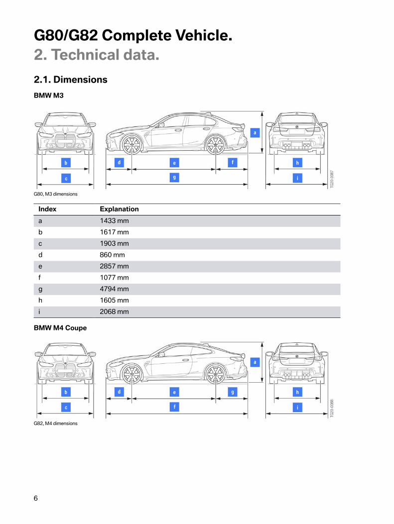
2.1.�DimensionsBMW�M3
G80,�M3�dimensions
Index Explanationa 1433�mmb 1617�mmc 1903�mmd 860�mme 2857�mmf 1077�mmg 4794�mmh 1605�mmi 2068�mm
BMW�M4�Coupe
G82,�M4�dimensions

G80/G82�Complete�Vehicle.2.�Technical�data.
7
Index Explanationa 1393�mmb 1617�mmc 1887�mmd 860�mme 2857�mmf 4794�mmg 1077�mmh 1605�mmi 2081�mm
2.2.�Comparison�of�technical�data
2.2.1.�BMW�M3The�BMW�M3�is�used�as�a�rear-wheel�drive�with�manual�transmission�from�production�date�November2020.
Designation Unit F80�M3 G80�M3Engine�series S55B30T0 S58B30O0Engine�control MEVD17.2.G DME�8.6.STransmission�type�designation GS6-45BZ
6-Speed�MTGS6-45BZ6-Speed�MT
Length [mm] 4671 4794Width�without�mirror [mm] 1877 1903Height [mm] 1424 1433Number�of�seats 5 5Luggage�compartmentvolume
[ft³] 16.9 16.9
Maximum�speed [mph] 155*/174** 155*/180**Acceleration�0-60 mp�h [s] 4.1 4.1Nominal�engine�powerat�engine�speed
[hp][rpm]
4255500-7300
4736250
Torque�at�speed [lb-ft][rpm]
4061850-5500
4062650-6130
Aerodynamicscx�(drag�coefficient)value)
0.34 0.33-0.34

G80/G82�Complete�Vehicle.2.�Technical�data.
8
Designation Unit F80�M3 G80�M3A�(area) [m2] 2.29 2.34
cx�x�A�(drag) [m2] 0.78 0.77-0.8
Vehicle�curb�weightDIN [lbs] 3640 3840Rear�axle�load�section,�empty(DIN)
[%] 48.2 47.1
Payload [lbs] 885 860Permissible�total�weight [lbs] 4630 4870Approximate�fuel�tankcapacity
[gal] 15.8 15.6
*�Electronically�limited.
**�with�M�Drivers�Package�(SA�7ME).
Please�always�compare�values�with�current�sales�documents�
2.2.2.�BMW�M3�CompetitionThe�BMW�M3�Competition�is�used�as�a�rear-wheel�drive�with�automatic�transmission�from�productiondate�November�2020.�The�BMW�M3�Competition�with�automatic�transmission�and�M�all-wheel�drive�MxDrive�is�used�from�production�date�July�2021.
Designation Unit F80�M3Competition
G80�M3Competition
Engine�series S55B30T0 S58B30T0Engine�control MEVD17.2.G DME�8.6.STransmission�type�designation GS7D36BG
7-speed�M�DKGM8HP768-speed�Mautomatictransmission
Length [mm] 4671 4794Width�without�mirror [mm] 1877 1903Height [mm] 1431 1433Number�of�seats 5 5Luggage�compartmentvolume
[ft³] 16.9 16.9
Maximum�speed [mph] 155*/174** 155*/180**

G80/G82�Complete�Vehicle.2.�Technical�data.
9
Designation Unit F80�M3Competition
G80�M3Competition
Acceleration�0-60 mph [s] 3.8 3.83.5***
Nominal�engine�powerat�engine�speed
[hp][rpm]
4447000
5036250
Torque�at�speed [lb-ft][rpm]
4062350-5500
4792750-5500
Aerodynamicscx�(drag�coefficient)value)
0.34 0.33-0.34
A�(area) [m2] 2.29 2.34
cx�x�A�(drag) [m2] 0.78 0.77-0.8
Vehicle�curb�weightDIN [lbs] 3865 3890Rear�axle�load�section,�empty(DIN)
[%] 47.9 46.9
Payload [lbs] 885 860Permissible�total�weight [lbs] 4675 4870Approximate�fuel�tankcapacity
[gal] 15.8 15.6
*�Electronically�limited.
**�with�M�Drivers�Package�(SA�7ME).
***�Expected�values�with�M�xDrive
Please�always�compare�values�with�current�sales�documents�
2.2.3.�BMW�M4�CoupeThe�BMW�M4�Coupe�is�used�as�a�rear-wheel�drive�with�manual�transmission�from�production�dateNovember�2020.
Designation Unit F82�M4 G82�M4Engine�series S55B30T0 S58B30T0Engine�control MEVD17.2.G DME�8.6.STransmission�type�designation GS6-45BZ
6-Speed�MTGS6-45BZ6-Speed�MT
Length [mm] 4671 4794

G80/G82�Complete�Vehicle.2.�Technical�data.
10
Designation Unit F82�M4 G82�M4Width�without�mirror [mm] 1870 1877Height [mm] 1383 1393Number�of�seats 4 4Luggage�compartmentvolume
[ft³] 15.7 15.5
Maximum�speed [mph] 155*/174** 155*/180**Acceleration�0-60 mph [s] 4.1 4.1Nominal�engine�powerat�engine�speed
[hp][rpm]
4256250
4736250
Torque�at�speed [lb-ft][rpm]
4062350-5500
4062650-6130
Aerodynamicscx�(drag�coefficient)value)
0.34-0.35 0.34
A�(area) [m2] 2.23 2.29
cx�x�A�(drag) [m2] 0.76 0.78
Vehicle�curb�weightDIN [lbs] 3625 3830Rear�axle�load�section,�empty(DIN)
[%] 47.7 47.3
Payload [lbs] 770 770Permissible�total�weight [lbs] 4500 4750Approximate�fuel�tankcapacity
[gal] 15.8 15.6
*�Electronically�limited.
**�with�M�Drivers�Package�(SA�7ME).
Please�always�compare�values�with�current�sales�documents�
2.2.4.�BMW�M4�Coupe�CompetitionThe�BMW�M4�Coupe�Competition�is�used�as�a�rear-wheel�drive�with�automatic�transmission�fromproduction�date�November�2020.�The�BMW�M4�Coupe�Competition�with�automatic�transmission�andM�all-wheel�drive�M�xDrive�is�used�from�production�date�July�2021.

G80/G82�Complete�Vehicle.2.�Technical�data.
11
Designation Unit F82�M4Competition
G82�M4Competition
Engine�series S55B30T0 S58B30T0Engine�control MEVD17.2.G DME�8.6.STransmission�type�designation GS7D36BG
7-speed�M�DKGM8HP768-speed�Mautomatictransmission
Length [mm] 4671 4794Width�without�mirror [mm] 1870 1877Height [mm] 1392 1393Number�of�seats 4 4Luggage�compartmentvolume
[ft³] 15.7 15.5
Maximum�speed [mph] 155*/174** 155*/180**Acceleration�0-60 mph [s] 3.8 3.8
3.5***Nominal�engine�powerat�engine�speed
[hp][rpm]
4446250
5036250
Torque�at�speed [lb-ft][rpm]
4062350-5500
4792750-5500
Aerodynamicscx�(drag�coefficient)value)
0.35-0.35 0.34
A�(area) [m2] 2.23 2.29
cx�x�A�(drag) [m2] 0.78 0.78
Vehicle�curb�weightDIN [lbs] 3685 3880Rear�axle�load�section,�empty(DIN)
[%] 47.4 46.9
Payload [lbs] 770 770Permissible�total�weight [lbs] 4545 4750Approximate�fuel�tankcapacity
[l] 15.8 15.6
*�Electronically�limited.
**�with�M�Drivers�Package�(SA�7ME).
***�Expected�values�with�M�xDrive

G80/G82�Complete�Vehicle.2.�Technical�data.
12
Please�always�compare�values�with�current�sales�documents�

G80/G82�Complete�Vehicle.3.�Body.
13
3.1.�Rigidity
3.1.1.�Chassis�and�suspension�components�and�rigidity�concept
Front�end�area�G80/G82
The�following�identical�measures�on�the�G80�and�G82�for�connecting�the�chassis�components�andincreasing�the�vehicle�rigidity�have�been�implemented�in�the�front�end�area:
• Strut�brace�bridge�made�of�steel.• Dome�firewall�strut�made�of�aluminum.• Dome�rings�made�from�aluminum�die�casting�alloy.• Front�end�struts�made�of�steel.• Cross-member�and�perforated�plate�made�of�steel.• Aluminum�stiffening�plate.• Front�axle�support�with�additional�connection�to�the�body�made�of�aluminum.• Vertical�struts�for�connecting�the�front�axle�support�to�the�engine�compartment�strut�structure
made�of�steel.
G82,�stiffness�measures�in�the�front�area

G80/G82�Complete�Vehicle.3.�Body.
14
Index Explanation1 Strut�brace�bridge2 Shock-tower-to-firewall�brace3 Dome�rings4 Front�end�struts5 Cross�member6 Perforated�plate7 Vertical�struts8 Front�axle�support�(rear-wheel�drive)9 Stiffening�plate
For�the�disassembly�and�installation�of�the�strut�package�of�the�front�end�or�parts�of�it,�the�screwingsequences�and�the�tightening�torques�must�be�observed.
For�necessary�service�work�the�current�information�and�specifications�in�the�documents�in�theIntegrated�Service�Technical�Application�(ISTA)�must�be�observed�in�each�case.
All�other�measures�for�stiffening�the�front�end�are�the�same�as�in�the�G20/G22�production�vehicle.
Rear�area�G80/G82
The�following�identical�measures�on�the�G80�and�G82�for�connecting�the�chassis�components�andincreasing�the�vehicle�rigidity�have�been�implemented�in�the�rear�area:
• Luggage�compartment�reinforcement�(draw�and�pressure�plate)�made�of�steel.• Rear�axle�support�screwed�to�the�body�made�of�steel.• Rear�axle�stiffening�plates�made�of�aluminum�with�stainless�steel�inserts�at�the�screw�points.• Tunnel�brace�made�of�aluminum�with�stainless�steel�inserts�at�the�screw�points.

G80/G82�Complete�Vehicle.3.�Body.
15
G82,�stiffness�measures�in�the�rear�area
Index Explanation1 Luggage�compartment�reinforcement2 Rear�axle�support3 Stiffening�plate,�left4 Tunnel�brace5 Stiffening�plate,�right
For�the�disassembly�and�installation�of�the�strut�package�or�parts�of�it�at�the�rear�area,�the�screwingsequences�and�the�tightening�torques�must�be�observed.
For�necessary�service�work�the�current�information�and�specifications�in�the�documents�in�theIntegrated�Service�Technical�Application�(ISTA)�must�be�observed�in�each�case.
All�other�measures�for�stiffening�the�rear�area�are�the�same�as�in�the�G20/G22�production�vehicle.

G80/G82�Complete�Vehicle.3.�Body.
16
3.2.�Exterior�trim
3.2.1.�Front
Bumper,�front
In�the�front�center�sits�the�strong�radiator�grill�of�the�BMW�4�Series�in�a�maximum�dynamic�andreduced�interpretation.
Streaks�may�form�with�the�use�of�an�automatic�car�wash�due�to�the�great�height�of�the�strong�radiatorgrill.�However,�they�can�be�easily�removed�with�suitable�cleaning�measures.
The�up-to-date�information�and�specifications�in�the�documents�in�AIR�(Aftersales�InformationResearch)�or�TSARA�(Technical�Support�and�Research�Assistant)�must�be�observed.
The�one-piece�bumper�panel�in�the�M-specific�design�which�is�painted�in�the�vehicle�color�has�flapsin�black�matte�on�the�bottom�left�and�right.�An�additional�front�spoiler�lip�made�of�rubber�in�black,�forreducing�the�lift�at�the�front�axle,�forms�the�base�of�the�bumper�at�the�front.�Due�to�the�necessary�airinlets�no�fog�lights�are�offered.�The�double-rib�kidney�bars�are�inside�the�BMW�M�radiator�grill,�likethe�radiator�grill�itself�they�are�in�high-gloss�black�for�the�G80�and�G82�and�the�BMW�M3�or�BMW�M4model�designation�is�in�chrome.�The�horizontal�alignment�of�the�double-rib�kidney�bars�ensures�afascinating�contrast�to�the�vertical�BMW�M�radiator�grill.�The�optional�side�view�camera�and�the�ParkingManeuvering�Assistant�PMA�sensors,�as�well�as�the�radar�sensors,�are�integrated�at�the�front/sidesimilarly�to�the�G20/G22�production�vehicle.
The�ornamental�grills�at�the�bottom�are�black.�Optionally,�radar�sensors�for�the�driver�assistancesystems�are�installed�in�the�front�bumper.
The�sill�extensions�in�the�bumper,�the�so-called�"skateboards",�form�the�base�of�the�bumper�panel.
The�large�optimized�air�ducts�in�the�ornamental�grills�on�the�left�and�right�and�the�vertical�radiator�grillguarantee�an�optimal�supply�of�cooling�air�for�ensuring�suitability�on�race�tracks�with�regard�to�driveand�brake�cooling.
G80/G82�Complete�Vehicle.3.�Body.
17
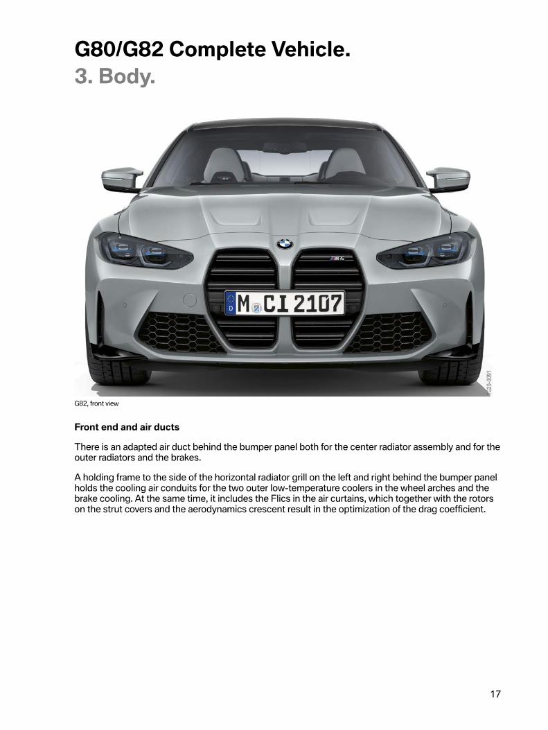
G82,�front�view
Front�end�and�air�ducts
There�is�an�adapted�air�duct�behind�the�bumper�panel�both�for�the�center�radiator�assembly�and�for�theouter�radiators�and�the�brakes.
A�holding�frame�to�the�side�of�the�horizontal�radiator�grill�on�the�left�and�right�behind�the�bumper�panelholds�the�cooling�air�conduits�for�the�two�outer�low-temperature�coolers�in�the�wheel�arches�and�thebrake�cooling.�At�the�same�time,�it�includes�the�Flics�in�the�air�curtains,�which�together�with�the�rotorson�the�strut�covers�and�the�aerodynamics�crescent�result�in�the�optimization�of�the�drag�coefficient.

G80/G82�Complete�Vehicle.3.�Body.
18
G80/G82,�Flics
Index Explanation1 Flics2 Rotor3 Aerodynamics�crescent4 Front�lip�spoiler
The�outside�temperature�sensor�is�located�in�the�air�curtain�on�the�right�in�the�G80/G82.�The�previousinstallation�location�for�the�outside�temperature�sensor�in�the�air�ducts�for�brake�system�cooling�wasnot�possible�in�the�G80/G82�since�the�measured�values�were�not�plausible�on�account�of�the�greaterheat�dissipated�by�the�S58�engine�and�brake�system�while�the�vehicle�is�at�a�standstill.
The�M�wheel�arch�cover�at�the�front�with�grills�for�discharging�the�cooling�air�from�the�low-temperaturecoolers�forms�the�base�of�the�bumper�panel�at�the�rear.
The�lower�bumper�support�is�made�of�sheet�steel�and�is�secured�at�specific�G80/G82�deformationelements.�The�shaped�element�in�the�upper�bumper�support�is�adapted�to�the�shape�of�the�G80/G82bumper�panel.
3.2.2.�HeadlightThe�front�headlights�are�carry-over�parts�from�the�G22/G23.�The�adaptive�LED�headlights�are�installedas�standard.�The�M-specific�bumper�panel�has�been�adapted�to�the�position�and�shape�of�theheadlights�on�the�G80/G82.

G80/G82�Complete�Vehicle.3.�Body.
19
3.2.3.�Engine�compartment�lidThe�separate�hood�on�the�G80/G82�is,�like�on�the�G20/G22,�made�of�aluminum.
The�supporting�inner�structure,�as�well�as�the�outer�skin�of�the�engine�compartment�lid,�are�made�fromaluminum.
The�lines�of�the�vertical�radiator�grill�continue�in�the�hood�and�end�at�the�windscreen.�Two�beadsbehind�the�respective�individual�radiator�grills�highlight�the�distinct�design�of�the�hood�of�the�G80/G82.
In�order�to�meet�the�requirements�with�regard�to�pedestrian�protection,�the�hood�is�equipped�with�anactive�pedestrian�protection�system.
3.2.4.�Side�view
G80,�side�view
G82,�side�view
Exterior�mirror�and�sill
As�standard,�the�M-specific�exterior�mirrors�are�heated�with�integrated�additional�indicators,�havememory�and�fold-in�functions,�and�the�front�passenger's�side�exterior�mirror�has�an�Automatic�CurbMonitor.�The�glass�for�each�mirror�also�contain�the�warnings�for�the�driver�assistance�systems.�Themirror�triangle�and�mirror�cap�at�the�bottom,�including�the�weather�strips�and�shaft�covers,�are�grainedas�standard.

G80/G82�Complete�Vehicle.3.�Body.
20
The�BMW�M3�and�BMW�M4�Coupe�exterior�mirrors�have�a�prominent�design�and�have�been�optimizedin�terms�of�their�aeroacoustic�properties.
The�door�sills�in�the�G80/G82�are�distinguished�by�their�widened�black�sills�compared�with�the�G20/G22,�which�has�the�effect�of�a�"skateboard"�in�the�G80/G82.�The�"skateboard"�sill�area�is�inspired�bymotorsport,�symbolizes�the�underbody�pulled�out�from�the�side�and�creates�the�connection�to�theroad.�The�skateboards�create�a�strong�visual�connection�to�the�road�and�are�more�dynamic.
G80/G82,�gill�and�mirror
With�the�standard�equipment�"Ambient�Lighting"�SA�4UR,�in�the�G80/G82�a�staged�light�carpet�bylight�projection�is�not�used�in�the�entry�and�exit�area�on�the�left�and�right.�The�required�space�for�thelight�projectors�is�not�available�in�the�sill�area�due�to�the�"skateboards"�of�the�G80/G82.
Front�side�panel
The�front�side�panels�in�the�G80/G82�are�new�due�to�the�M-specific�design�and�made�of�aluminum,they�are�also�new�with�regard�to�the�tire�clearance.
Striking�design�features�include�the�so-called�M�side�gills�and�the�BMW�M3/BMW�M4�modeldesignation�on�the�front�left�and�right�side�panels.
Wheel�arch�cover
The�wheel�arch�cover�and�the�covers�of�the�steering�assemblies�are�adapted�to�the�new�side�panel.�Inaddition,�the�covers�of�the�steering�assemblies�in�the�all-wheel�drive�are�different�to�the�vehicle�withrear-wheel�drive.
Roof
The�roof�operating�unit�for�the�G80/G82�is�made�from�a�carbon�fiber�structure�and�is�connected�to�thebody�by�bonding.�The�roofline�has�an�aerodynamic�outline�in�the�middle�section,�thus�highlighting�thesporting�character�of�the�G80/G82.

G80/G82�Complete�Vehicle.3.�Body.
21
The�use�of�a�CFRP�roof�produces�a�weight�saving�of�3.3�lbs�compared�with�the�standard�steel�roofon�the�G20/G22�.�The�weight�saving�in�the�roof�area�increases�the�vehicle's�agility�and�dynamics�bylowering�the�center�of�gravity�towards�the�road.
The�production�of�the�CFRP�roof�is�constructed�as�a�multilayer�design�in�wet�compression�processand�is�sealed�with�a�layer�of�clear�coat.
If�the�customer�decides�in�favor�of�an�electrical�glass�moonroof�SA�403�in�the�G80/G82,�the�CFRP�roofis�deleted�and�a�steel�roof�as�in�the�G20/G22�is�installed.
The�electrical�glass�moonroof�SA�403�is�not�offered�for�the�G80/G82�with�M�Drivers�Package�7ME.A�pressure�resistance�of�the�glass�moonroof�cannot�be�guaranteed�from�155�mph,�therefore�it�is�notused�for�the�G80/G82�M�Drivers�Package�7ME.
G80,�CFRP�roof

G80/G82�Complete�Vehicle.3.�Body.
22
Rear�side�panel
The�rear�side�panels�in�the�G80/G82�are�new�due�to�the�M-specific�design�and�are�made�of�steel.In�addition,�they�are�also�new�in�relation�to�the�accommodation�of�the�M-specific�axles�and�therequired�tire�clearance�of�the�BMW�M�wheels.�Therefore,�the�side�panels�are�very�wide,�thus�providingextremely�brawny�wheel�arches.
Wheel�arch�cover
The�wheel�arch�cover�has�been�adapted�to�the�new�side�panel.�To�ensure�the�legally�required�wheelarch�area�cover�in�the�rear,�in�the�G80/G82�wheel�arch�covers�made�of�plastic�are�installed�on�the�rearside�panel,�continuing�on�from�the�wheel�arch�extensions.�The�dimensions�of�the�covers�are�adapted�tothe�country�regulations�in�each�case�and�therefore�vary�with�the�national-market�version.
3.2.5.�Rear�viewA�striking�design�feature�is�the�4�round�exhaust�tailpipes.
G80,�rear�view

G80/G82�Complete�Vehicle.3.�Body.
23
G82,�rear�view
The�rear�bumper�panel�is�a�BMW�M3�and�BMW�M4�Coupe�design�and�is�different�in�the�G80/G82�dueto�the�different�styling�of�the�trunk.�It�is�painted�in�the�vehicle�color,�including�the�PDC�sensors,�andincludes�the�vertical�rear�reflectors�at�the�side,�which�set�the�typical�M�accent�at�the�rear.
The�rear�view�of�the�BMW�M3�with�the�extended�wheel�arches�creates�associations�with�the�distinctiverear�wheel�section�of�the�first�BMW�M3�(E30).
The�optional�radar�sensors�for�the�driver�assistance�systems�of�the�G80/G82�are�integrated�at�the�rear/sides,�similar�to�the�G20/G22�production�vehicle.
The�M-specific�diffuser�has�been�specifically�adapted�to�the�4�exhaust�tailpipes�and�is�painted�in�thevehicle�color.�The�sill�extensions�in�the�bumper,�the�so-called�"skateboards",�form�the�base�of�thebumper�panel.
3.2.6.�Rear�lights
LED�TAIL�LIGHTS�G80
The�tail�lights�of�the�BMW�M3�are�fully�implemented�in�high-quality�LED.�A�striking�element�is�thestraight,�extensively�illuminated�tail�light�bar�in�the�typical�BMW�L�shape.�It�fits�in�perfectly�with�themodern�appearance�of�the�rear.�The�lights�are�further�emphasized�by�the�use�of�smoked�glass,�whichmakes�the�entire�contour�appear�slim�and�athletic.

G80/G82�Complete�Vehicle.3.�Body.
24
LED�TAIL�LIGHTS�G82
With�their�slim�contour�the�full�LED�tail�lights�highlight�the�sporty�horizontal�alignment�of�the�BMW�M4Coupe�rear�and�the�position�on�the�road.�When�active�the�three-dimensional�outer�glass�appears�toglow�red.�This�energetic�interpretation�of�the�striking�L�shape�in�the�form�of�a�large�LED�light�elementmakes�the�rear�very�recognizable�as�a�BMW�M4�Coupe.�The�light�extends�to�the�side�panel,�thuscreating�a�dynamic�transition�from�side�and�rear�sections.�In�the�transparent�section�of�the�tail�lights,which�is�darkened�by�the�smoky�glass,�horizontal�outer�discs�break�up�the�lighting�design�and�set�amodern�and�elegant�accent.
3.2.7.�TailgateThe�tailgate�of�the�G80/G82�is�a�standard�part�adopted�from�the�G20/G22.�The�tailgate�is�enhancedwith�a�M-specific�Gurney�(rear�lip�spoiler)�(BMW�M4�in�vehicle�color).�The�rear�diffuser�and�the�Gurneyreduce�the�rear�axle�drive,�in�particular�at�higher�speeds.
A�Gurney�is�an�aerodynamic�component�and�functions�as�a�tear-off�edge.�The�Gurney�was�so-called�after�a�former�Formula�1�driver.�The�Gurney�reduces�the�drive�power�at�the�rear�axle�and�thuscontributes�to�the�optimization�of�the�driving�dynamics.
With�Comfort�Access�SA�322�in�conjunction�with�automatic�tailgate�operation�SA�316,�the"Contactless�opening�and�closing�of�the�tailgate"�function�is�not�available�for�the�G80/G82�with�theoptional�equipment�SA�71C�M�Carbon�exterior�package�(carbon�diffuser).
With�the�2nd�generation�of�Comfort�Access�SA�322,�a�third�aerial�is�installed�in�the�rear�area�in�theG80/G82.�This�makes�automatic�locking�and�unlocking�with�Comfort�Access�2.0�possible�whenapproaching/walking�away�from�the�vehicle�across�the�entire�area�of�the�vehicle.
3.2.8.�Sound�insulationIn�order�to�save�weight�in�the�G82�in�the�course�of�the�lightweight�construction�potential,�the�followinginsulating�materials�are�deleted�for�the�sound�insulation�for�the�interior:
• Insulating�material�for�the�sealing�of�the�C-pillar�over�the�wheel�arch,�rear�left�and�right.• Insulating�material�for�sound�insulation�of�A-pillar�at�bottom�to�door�wiring�harness,�left�and
right.• Insulating�material�for�sound�insulation�of�A-pillar�in�the�middle�in�the�area�above�the�cowl
panel,�left�and�right.• Insulating�material�for�sound�insulation�of�A-pillar�in�the�middle�in�the�area�below�the�cowl
panel,�left�and�right.• Insulating�material�for�sound�insulation�of�A-pillar�to�the�sill�transition,�bottom�left.
Compared�to�the�production�vehicle�G22,�there�are�noticeable�losses�of�comfort�for�the�customer�inthe�area�of�the�interior�noises�due�to�the�design�with�the�deletion�of�the�sound�insulation�in�the�G82.
3.2.9.�Underbody,�thermal�protection�and�cooling

G80/G82�Complete�Vehicle.3.�Body.
25
Underbody
The�complete�underbody�is�fully�panelled�as�part�of�the�aerodynamic�concept�of�the�G80/G82�in�orderto�reduce�and�uniformly�distribute�the�lift�at�the�front�and�rear�axles.�This�highlights�and�optimizes�thedriving�dynamics�concept,�particularly�at�higher�speeds.�The�underbody�panelling�was�adapted�interms�of�the�cooling�and�flow�around�and�through�the�drive�components�and�chassis�and�suspensioncomponents,�without�compromising�the�aerodynamics.
Underbody�panelling
New�underbody�panelling:
• The�specific�engine�compartment�shielding�in�the�middle.�It�includes�in�the�center�the�air�ductof�the�horizontal�engine�oil�cooler�and�optimizes�its�flow.
• Specific�cover�of�the�steering�assemblies�in�the�all-wheel�drive�to�the�vehicle�with�rear-wheeldrive,�left�and�right.
• Two-part�wheel�arch�covers,�left�and�right�front• Thrust�arm�covers,�left�and�right,�with�rotors• Undershields,�center�left�and�right• Undershields,�fuel�tank,�left�and�right• One-part�wheel�arch�covers,�rear�left�and�right• Rear�diffuser.
Heat�shield:
• Heat�shield,�engine�mount,�right• Heat�shield,�engine�mount�for�transition�to�firewall• Heat�shield�for�the�M�Electronic�Power�Steering�(M�EPS)• Heat�shield�at�the�side�to�the�left�of�the�automatic�transmission• Heat�shield�at�the�side�to�the�right�of�the�automatic�transmission• Heat�shield�of�the�tunnel• Heat�shield�above�the�gasoline�particulate�filter�to�the�tank• Heat�shield�of�the�luggage�compartment• Heat�shield�of�the�rear�silencer,�front�and�rear• Heat�shield�of�the�rear�silencer,�left�and�right.
Wheel�rim�design,�standard�equipment
Forged�18"�M�light-alloy�wheels�are�used�as�standard�at�the�front�and�19"�M�light-alloy�wheels�areused�as�standard�at�the�rear.�Mixed�tires�with�the�sizes�275/40�ZR18�at�the�front�and�285/35�ZR19�atthe�rear�are�used.

G80/G82�Complete�Vehicle.3.�Body.
26
G80/G82,�wheel�rim�design,�standard�equipment
Index Explanation1 18"/19"�M�wheel�824M
Wheel�rim�design,�optional�equipment
The�forged�M�light-alloy�wheels�with�19"�at�the�front,�20"�at�the�rear�with�mixed�tires�in�the�size�275/35ZR19�at�the�front�and�285/30�ZR20�at�the�rear�can�also�be�ordered�as�optional�equipment.�For�moreinformation�please�see�the�chapter�"Wheels/Tires".
G80/G82,�wheel�rim�design,�optional�equipment
Index Explanation1 19"/20"�M�wheel�825M�Jet�Black�Bi-color2 19"/20"�M�wheel�825M�Orbit�Grey�Matte3 19"/20"�M�wheel�826M�Jet�Black�Bi-color4 19"/20"�M�wheel�826M�Jet�Black

G80/G82�Complete�Vehicle.3.�Body.
27
3.3.�Interior�equipment
3.3.1.�Driving�area�and�steering�wheel
M�driving�area
G80/G82,�M�vehicle�cockpit�(example�of�BMW�M4)
M�leather�steering�wheel
The�M�leather�steering�wheel�with�MFL�is�built�on�a�magnesium�skeleton�and�is�based�on�the�steeringwheel�used�with�the�F90�M5.�Above�the�thumb�rests�are�the�M�shift�paddles�with�M�gearshift�logic:downshift�on�the�left,�upshift�on�the�right.
The�steering�wheel�has�increased�in�its�outer�diameter�to�380 mm�compared�with�the�G20/G22.�Thesteering�wheel�rim�is�reinforced�and�ergonomically�optimized�from�a�round�to�an�oval�cross-section,improving�the�driver's�grip.
Shift�paddle�(with�automatic�transmission)�left�"-"�downshift,�right�"+"�upshift.
The�colored�M�stitching�constitutes�another�difference�from�the�production�steering�wheels.�TheM�leather�steering�wheel�in�the�double-spoke�design�with�a�stainless�steel�center�trim�and�with�Minscription�is�black�leather.
The�vibration�element�for�lane�departure�warning�and�lane�change�warning�is�integrated�in�the�steeringwheel.

G80/G82�Complete�Vehicle.3.�Body.
28
There�are�2�red�M�buttons�mounted�on�top�of�the�multifunction�pad�because�the�multifunction�buttonclusters�for�the�driver�assistance�systems�remain�on�the�steering�wheel�as�on�the�G20/G22.�For�moredetails,�please�see�the�chapter�"M�menu".
G80/G82,�M�leather�steering�wheel�(example�of�BMW�M4)
With�the�optional�equipment�M�carbon�interior�trims�SA�4MC,�the�steering�wheel�decorative�panelsand�the�shift�paddles�in�conjunction�with�the�automatic�transmission�are�designed�in�carbon.
3.3.2.�Seats
M�sports�seats
The�fully�electric�M�sport�seats�are�standard�equipment�and�are�carried�over�from�the�F97/F98.
These�are�fully�electric�sports�seat�with�integrated�side�airbag�and�a�seat�belt�buckle�pretensioner.�Theseats�are�operated�by�means�of�a�control�switch�on�each�seat.�The�3�memory�functions�for�the�driver'sseat�can�be�called�up�via�the�3�buttons�in�the�seat�panel.�The�control�unit�is�installed�at�the�bottom�ofthe�seat.�To�increase�safety,�the�crash-active�head�restraints�are�installed�as�standard.
M�seat�features�(driver�and�front�passenger):
• Fine-grain�Merino�leather�with�perforated�3D�stitching,�one-color�or�two-color• Heated�seats• Electrically�adjustable�seat�length,�height,�tilt�and�backrest�angle• Electric�headrest�height�adjustment• Pneumatic�lumbar�support• Pneumatic�backrest�width�adjustment

G80/G82�Complete�Vehicle.3.�Body.
29
• Manual�seat�depth�adjustment• Illuminated�M�logo�in�the�head�restraint• In�the�"Parking"�state�the�head�restraint�travels�downwards�fully�into�the�rest�state.
Optional�equipment�for�the�M�sports�seat
• Active�seat�ventilation�as�optional�equipment�SA�453�for�G80�and�G82• Memory�function�for�the�driver's�seat
The�following�additional�changes�have�been�made�in�the�area�of�the�M�sport�seats�for�the�G80/G82:
• The�G80�has�active�seat�ventilation�like�the�G82�(in�contrast:�No�seat�ventilation�is�offered�forthe�G20).
• In�order�to�allow�the�"Park"�status�of�the�head�restraints�on�both�front�seats,�the�G80�also�has�afront�passenger�seat�module�SMBF�high�on�the�passenger's�side.
M�CFRP�bucket�seat
A�M�CFRP�bucket�seat�can�be�ordered�as�optional�equipment�for�the�G80/G82.�The�M�CFRP�bucketseat�has�a�weight�advantage�of�19.8 lbs�compared�with�the�M�sport�seat.
M�CFRP�bucket�seat�features�(driver�and�front�passenger):
• Fine-grain�Merino�leather• Heated�seats• Electrically�adjustable�seat�length,�height,�tilt�and�backrest�angle• Pneumatic�backrest�width�adjustment• Illuminated�M�logo�in�the�head�restraint• Memory�function�as�optional�equipment�for�the�driver's�seat.

G80/G82�Complete�Vehicle.3.�Body.
30
G80/G82,�M�CFRP�bucket�seat
Index Explanation1 View�from�front2 View�from�rear
The�M�CFRP�bucket�seat�offers�the�following�customer�benefits:
• Combination�of�properties�of�a�full�bucket�seat�with�the�functionality�of�a�M�sport�seat.• Distinctive�racing�seat�contour�with�lightweight�construction�openings�in�backrest�and�side
bolsters,�as�well�as�functional�belt�guides�for�six-point�safety�belts.• Bucket�seat�character�with�ideal�basic�contour�of�seat�for�optimal�long-distance�comfort.• Improved�side�support�thanks�to�design�of�the�side�contact�surfaces�in�black�Alcantara
(regardless�of�the�selected�upholstery�color).• Functional,�supporting�CFRP�structure�with�visible�carbon�areas,�also�complete�backrest�and
center�section�of�seat�surface.• Fully�electric�adjustment�of�seat�height,�seat�tilt�and�backrest�tilt�including�memory�for�driver's
side.• Option�to�remove�the�headrest�to�create�more�room�for�driving�with�helmet�on�the�race�track.

G80/G82�Complete�Vehicle.3.�Body.
31
Rear�seats
The�full-foam�seat�in�3-seater�version�for�the�G80�and�2-seater�version�for�the�G82�with�armrest�andseat�division�is�adopted�from�the�G20/G22.�The�split�ratio�is�40/20/40.
A�cupholder�in�the�center�armrest�is�not�offered�in�the�G80/G82.
Optional�equipment�for�the�rear�seat
• Heated�seats• Remote�backrest�unlocking�from�the�luggage�compartment
3.3.3.�Seat�beltsThe�seat�belts�of�the�G80/G82�with�Competition�package�SA�7MA�have�contrast�stitching�in�the�BMWM�colors�as�standard.
A�seat�belt�extender�is�not�offered�in�the�G82�compared�with�the�G22.
3.3.4.�Doors�and�strips
Doors
Upper�door�trims�(shoulders)�in�“black�soft�nappa"�leather�with�contrast�stitching.
M�decorative�strips
The�following�trims�are�offered�in�the�G80/G82:
• High-gloss�black• Aluminum�Tetragon• Carbon�fiber.
With�the�optional�equipment�M�carbon�interior�trims�SA�4MC,�the�decorative�trims�of�the�centerconsole,�including�the�lid�for�the�storage�compartment,�as�well�as�the�decorative�strip�of�the�instrumentpanel�on�the�passenger's�side,�are�designed�in�carbon�fiber.
Sill�trims,�footrest�and�compact�spare�wheel
• Sill�trims�with�M�lettering• Competition�package�SA�7MA�with�illuminated�"Competition"�lettering• M�footrest�(LHD�only)• An�emergency�spare�wheel�is�not�offered�for�the�G80/G82.�A�Mobility�Set�is�included�with�the
vehicle�as�standard.
G80/G82�Complete�Vehicle.4.�Drive.
32
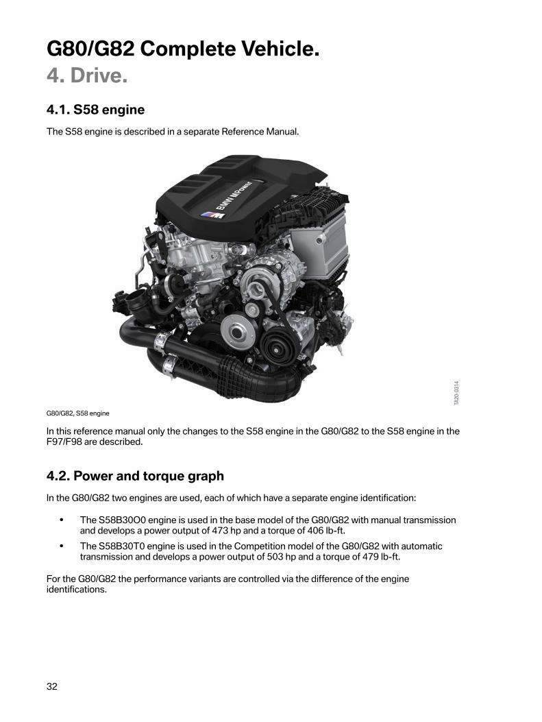
4.1.�S58�engineThe�S58�engine�is�described�in�a�separate�Reference�Manual.
G80/G82,�S58�engine
In�this�reference�manual�only�the�changes�to�the�S58�engine�in�the�G80/G82�to�the�S58�engine�in�theF97/F98�are�described.
4.2.�Power�and�torque�graphIn�the�G80/G82�two�engines�are�used,�each�of�which�have�a�separate�engine�identification:
• The�S58B30O0�engine�is�used�in�the�base�model�of�the�G80/G82�with�manual�transmissionand�develops�a�power�output�of�473 hp�and�a�torque�of�406�lb-ft.
• The�S58B30T0�engine�is�used�in�the�Competition�model�of�the�G80/G82�with�automatictransmission�and�develops�a�power�output�of�503 hp�and�a�torque�of�479�lb-ft.
For�the�G80/G82�the�performance�variants�are�controlled�via�the�difference�of�the�engineidentifications.

G80/G82�Complete�Vehicle.4.�Drive.
33
G80/G82,�S58B30O0�engine,�performance�diagram
4.3.�Air�intake�ductThe�air�duct�of�the�S58�engine�was�adapted�to�the�installation�position�of�the�G80/G82.�The�air�ducthas�been�optimized�for�minimum�loss�of�pressure�in�order�to�achieve�the�level�despite�the�increasedair�flow�rates�in�contrast�to�the�F80/F82�and�F83.�This�is�also�assisted�by�the�deletion�of�a�hot�film�airmass�meter,�as�with�the�S58�engine�in�the�F97/F98.�The�two�intake�silencers�in�the�air�intake�ductcontain�large�air�filter�inserts�and�an�additional�HC�fleece�in�the�upper�parts�of�the�intake�silencers�forthe�US�equipment�specifications.

G80/G82�Complete�Vehicle.4.�Drive.
34
G80/G82,�air�intake�duct
Index Explanation1 Unfiltered�air�inlet,�cylinder�bank�22 Intake�silencer,�cylinder�bank�23 Lid�of�intake�silencer,�cylinder�bank�2�(with�HC�fleece�for�US�equipment
specifications)4 Clean�air�line,�cylinder�bank�25 Clean�air�line,�cylinder�bank�16 Lid�of�intake�silencer,�cylinder�bank�1�(with�HC�fleece�for�US�equipment
specifications)7 Intake�silencer,�cylinder�bank�18 Unfiltered�air�inlet,�cylinder�bank�1
The�intake�of�the�untreated�air�is�realized�in�the�G80/G82�in�the�area�behind�the�headlights,�comparedwith�the�intake�upstream�from�the�radiator�in�the�F80/F82�and�F83.�This�gives�the�G80/G82�theopportunity�to�meet�the�requirements�of�a�water�crossing�despite�the�absence�of�an�air�flap�control�andthus�ensure�increased�safety�of�the�fording�ability.

G80/G82�Complete�Vehicle.4.�Drive.
35
4.4.�CrankshaftThe�crankshaft�drive�has�been�optimized�to�the�specific�requirements�for�torque,�output�and�rotationalspeed.�For�improved�response�characteristics�of�the�engine,�a�new�weight-optimized�lightweightconstruction�crankshaft�is�used�for�the�first�time�in�the�S58�engine�in�the�G80/G82.
4.5.�Engine�mountThe�right�engine�mount�of�the�S58�engine�in�the�G80/G82�is�more�rigid�than�the�left�engine�mount.The�torque�increase�of�36�lb-ft�in�the�G80/G82�compared�with�the�F97/F98�results�in�better�support�ofthe�engine�torque�at�the�front�axle�support.�This�reduces�force�applications�by�the�drive�system�duringthe�build-up�of�the�torque�by�the�S58�engine�from�the�rest�of�the�drivetrain�of�the�vehicle.
4.6.�Oil�pumpFor�the�S58�engine,�like�for�the�S63TU4�engine,�a�so-called�external�gear�pump�with�integratedsuction�pump�is�used.�This�combination�is�more�compact�at�a�higher�delivery�rate�than�the�volume-flow-controlled�pendulum-slide�pump�for�the�S55�engine.
Please�note�the�following�information�due�to�the�design�of�the�external�gear�pump�for�the�S58�engineand�in�the�S63B44T4�engine:
At�low�outside�temperatures�and�with�the�low�viscosity�of�the�engine�oil,�increased�operating�noises�ofthe�oil�pump�may�occur.�These�increased�operating�noises�at�low�outside�temperatures�are�due�to�thedesign�with�the�concept�of�the�oil�pump�as�an�external�gear�pump�and�do�not�represent�a�malfunction.
The�up-to-date�information�and�specifications�in�the�documents�in�AIR�(Aftersales�InformationResearch)�or�TSARA�(Technical�Support�and�Research�Assistant)�must�be�observed.
Further�information�about�the�S58�engine�and�the�S63�engine�can�be�found�in�the�reference�manuals"ST1926�S58�Engine"�and�"ST1916�S63TU4�Engine".
4.7.�Oil�sumpDepending�on�the�drive�concept,�for�the�S58�engine�in�the�G80/G82�an�engine�oil�sump�for�all-wheeldrive,�with�the�apertures�for�the�front�drive�shaft�or�an�engine�oil�sump�for�rear-wheel�drive�is�installed.

G80/G82�Complete�Vehicle.4.�Drive.
36
4.8.�Exhaust�system
4.8.1.�Overview�of�available�exhaust�systems
Standard�exhaust�system ECE�Europe�version US�versionUpstream�catalytic�converter Underbody�catalytic�converter Petrol�particulate�filter Not�used�in�US�marketFront�oxygen�sensor Monitoring�oxygen�sensor Differential�pressure�sensor,gasoline�particulate�filter Not�used�in�US�market
Temperature�sensor�upstreamof�gasoline�particulate�filter Not�used�in�US�market
Temperature�sensordownstream�of�gasolineparticulate�filter
Not�used�in�US�market
Exhaust�flap Chrome-plated�tailpipe�trims Continuous�exhaust�flap Competition�modelBlack�chrome-plated�tailpipetrim
4.8.2.�Catalytic�converterThe�S58�engine�in�the�G80/G82�has�2�catalytic�converters,�1�catalytic�converter�near�engine,�each�with2�ceramic�monoliths,�and�1�underbody�catalytic�converter�with�metal�monolith,�per�cylinder�bank.
The�routing�of�the�exhaust�system�has�been�modified�at�the�underbody.�Unlike�other�vehicle�modelswith�6-cylinder�engine,�the�exhaust�system�for�the�G80/G82�is�not�directed�past�the�transmission�withtwo�exhaust�pipes�on�the�right,�but�is�directed�past�the�transmission�in�a�Y-shape�on�the�left�and�right.This�allows�more�installation�space�for�the�two�larger�underbody�catalytic�converters.
In�order�to�keep�the�exhaust�gas�pressure�for�the�S58�engine�as�low�as�possible,�the�largest�possiblepipe�diameter�has�been�selected;�this�makes�it�possible�to�ensure�the�highest�level�of�efficiency�for�thetwo�single-scroll�exhaust�turbochargers.

G80/G82�Complete�Vehicle.4.�Drive.
37
G80/G82,�catalytic�converters
Index Explanation1 Lambda�oxygen�sensor�LSU�5.22 Catalytic�converter�near�engine,�bank�23 Underfloor�catalytic�converter,�bank�14 Underfloor�catalytic�converter,�bank�25 Monitoring�oxygen�sensor�LSF�Xfour6 Catalytic�converter�near�engine,�bank�1
4.8.3.�Exhaust�system
• M-specific,�emotive�startup�sound�on�engine�starting• Sporty�and�unmistakable�feedback�of�the�exhaust�sound�to�the�vehicle�occupants.
G80/G82�Complete�Vehicle.4.�Drive.
38
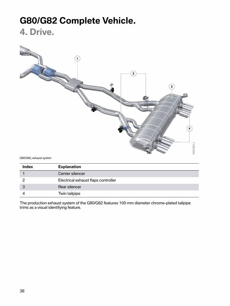
G80/G82,�exhaust�system
Index Explanation1 Center�silencer2 Electrical�exhaust�flaps�controller3 Rear�silencer4 Twin�tailpipe
The�production�exhaust�system�of�the�G80/G82�features�100 mm�diameter�chrome-plated�tailpipetrims�as�a�visual�identifying�feature.

G80/G82�Complete�Vehicle.4.�Drive.
39
G80/G82,�rear�silencer
Index Explanation1 Electrical�exhaust�flaps�controller2 Bypass�pipe3 Absorption�silencer4 Twin�tailpipe
4.8.4.�Electrically�controlled�exhaust�flaps
Electrically�controlled�exhaust�flap(s)
The�exhaust�flap�is�integrated�into�the�rear�silencer�in�the�outer�exhaust�tailpipes.�The�exhaust�flap�isoperated�by�an�axially�arranged�electric�motor�with�integrated�gears�and�electronics.�The�electricalcontroller�for�the�exhaust�flap�has�the�following�connections:
• Voltage�supply�(+)• Ground�(-)• Actuating�wire�(signal�line)

G80/G82�Complete�Vehicle.4.�Drive.
40
The�exhaust�flaps�furthermore�help�to�suppress�frequencies�that�are�perceived�as�unpleasant�andthereby�improve�driving�comfort.�At�high�engine�speeds�and�high�engine�loads,�the�exhaust�gascounterpressure�can�be�reduced�by�opening�the�exhaust�flap.
The�exhaust�flap�is�activated�(using�pulse�width�modulation)�by�the�Digital�Motor�Electronics�(DME).The�input�variables�are:
• Engine�speed• Engine�load• Driving�speed
Electrical�exhaust�flap S58�engineInstallation�location right�and�leftPWM�signal�open 10%�duty�cyclePWM�signal�closed 90%�duty�cycle
The�exhaust�flaps�of�the�exhaust�system�can�achieve�intermediate�settings.�Therefore,�it�is�possible�forthe�exhaust�flaps�to�be�continuously�variably�adjusted�to�any�position.
The�exhaust�flaps�are�actuated�in�accordance�with�demand�and�can�be�set�via�the�function�of�theSETUP�button�in�the�central�information�display�(CID)�to�"EFFICIENT",�"SPORT"�and�"SPORT+".
The�position�of�the�exhaust�flaps�can�additionally�be�influenced�by�means�of�the�sound�button�in�thecenter�console�switch�cluster.�Because�no�default�value�is�stored�in�the�"EFFICIENT"�engine�dynamicscontrol�for�the�engine�start�sound�that�would�lower�the�noise�level,�it�is�possible�that�this�would�havean�unfavorable�effect�on�the�sound�produced�by�the�vehicle�in�residential�areas.�For�this�reason,�theexhaust�flaps�can�be�influenced�and�closed�independently�of�the�engine�dynamics�control�settingto�EFFICIENT,�SPORT�or�SPORT+�via�the�sound�button.�By�pressing�the�sound�button,�the�soundproduced�can�quickly�be�changed�to�a�quieter�exhaust�sound�without�influencing�the�engine�dynamicscontrol�settings.
The�sound�button�is�connected�with�the�Body�Domain�Controller�BDC�via�a�LIN�bus.
4.9.�Cooling
4.9.1.�System�overviewThe�engine�and�charge�air�cooling�both�have�separate�cooling�circuits.
Differences�in�cooling�between�G80/G82�and�F97/F98:
• Omission�of�the�external�low-temperature�charge�air�cooler�on�the�right.• Additional�external�radiator�on�the�right�of�engine.• All�coolant�radiators�are�protected�by�a�stone�chip�protective�grid�made�of�plastic.

G80/G82�Complete�Vehicle.4.�Drive.
41
In�order�to�ensure�the�cooling�power�of�the�cooling�system�in�the�S58�engine�even�in�extreme�racetrack�applications,�the�external�low-temperature�charge�air�cooler�on�the�right�is�deleted.�An�additionalexternal�radiator�is�installed�in�its�place.
G80/G82,�radiator/cooler�assembly�from�front
Index Explanation1 External�radiator�with�stone�chip�protective�grid2 Expansion�tank,�high-temperature�circuit3 Expansion�tank,�low-temperature�circuit4 Indirect�charge�air�cooler5 Radiator,�engine6 Low-temperature�cooler,�charge�air7 Engine�oil�cooler8 Transmission�oil�cooler9 Air�conditioning�condenser

G80/G82�Complete�Vehicle.4.�Drive.
42
The�aforementioned�changes�are�carried�over�as�of�production�date�11/2020�for�the�S58B30T0engine�in�the�F97/F98.
It�is�absolutely�essential�to�observe�the�up-to-the-minute�information�and�specifications�of�thedocuments�with�regard�to�the�cooling�system�filling�capacities�in�the�Integrated�Service�TechnicalApplication�(ISTA).
G80/G82,�complete�cooling�system�without�oil�cooling,�schematic

G80/G82�Complete�Vehicle.4.�Drive.
43
Index Explanation1 Low-temperature�cooler,�charge�air2 External�radiator,�engine�right3 Radiator,�engine4 Electric�coolant�pump,�low-temperature�circuit,�charge�air�130 W5 Coolant�expansion�tank,�engine6 Indirect�charge�air�cooler7 Heater,�characteristic�map�thermostat8 Data-map�thermostat9 Mechanical�coolant�pump10 Electric�coolant�pump,�exhaust�turbocharger�20 W11 Exhaust�turbocharger12 Coolant�temperature�sensor13 Heat�exchanger�for�heating�system14 Electric�coolant�pump,�heating,�vehicle�interior15 Coolant-cooled�throttle�valve16 Coolant�expansion�tank,�low-temperature�circuit,�charge�air17 Electric�fan�1 kW18 External�radiator,�engine�left
4.9.2.�Engine�oil�coolingThe�S58�engine�has�an�external�air-oil�heat�exchanger�for�cooling�the�engine�oil�which�is�built-in�flat�infront�of�the�cooling�module.�To�quickly�heat�up�the�engine�oil,�a�thermostat�is�integrated�in�the�uppersection�of�the�engine�oil�sump.�The�thermostat�releases�the�flow�to�the�engine�oil�cooler�as�of�anengine�oil�temperature�of�100�°C�(212�°F)�and�is�fully�open�at�an�engine�oil�temperature�of�145�°C�(293°F).

G80/G82�Complete�Vehicle.4.�Drive.
44
S58�engine,�engine�oil�cooling
Index Explanation1 Upstream�engine�oil�cooler2 Return�line3 Oil�filter�housing4 Thermostat5 Feed�line
4.9.3.�Cooling�power�limitsIf�under�extreme�conditions�such�as�for�example�in�countries�with�high�outside�temperatures�and�thecooling�power�reaching�its�limits�on�the�race�track�under�race�conditions,�the�cooling�power�of�thevehicle�air�conditioning�is�reduced�as�the�very�first�measure.�Reducing�the�cooling�power�for�the�airconditioning�ensures�that�there�is�sufficient�cooling�power�available�for�the�engine�cooling�and�chargeair�cooling.�If�the�cooling�power�for�the�engine�cooling�and�charge�air�cooling�still�cannot�be�ensuredeven�after�the�cooling�power�of�the�air�conditioning�has�been�eliminated,�the�engine�performanceand�engine�speed�are�gradually�reduced�before�the�CC�message�is�displayed.�In�this�way,�constantand�rapid�lap�times�over�a�lengthy�period�can�be�achieved�on�the�race�track�even�at�high�ambienttemperatures.�The�customer�is�alerted�by�a�Check�Control�message�if�the�cooling�power�of�the�enginecooling�or�charge�air�cooling�reaches�its�limits.�In�the�event�of�a�customer�complaint�relating�to�thecooling�power�of�the�vehicle's�air�conditioning�system,�it�is�essential�first�to�take�these�conditions�intoconsideration�before�starting�troubleshooting�on�the�cooling�system�and�on�the�air�conditioning.
G80/G82�Complete�Vehicle.4.�Drive.
45
For�necessary�servicing�and�further�guidance�about�driving�on�the�race�track,�the�current�informationand�specifications�in�the�documents�in�the�Integrated�Service�Technical�Application�(ISTA)�must�beobserved�in�each�case.
4.10.�Fuel�preparationRegarding�the�fuel�treatment�the�following�changes�have�been�made�compared�to�the�G20/G22�basicvehicle.
4.10.1.�Low-pressure�fuel�system
• For�the�surge�tank�with�the�electric�fuel�pump�in�the�fuel�tank,�in�the�G80/G82�a�differentdelivery�unit�is�used�than�in�the�production�vehicle�G20/G22.�The�reason�for�this�is�that�thenecessary�delivery�volume�of�the�electric�fuel�pump�of�the�G20/G22�for�safely�filling�the�surgetank�during�acceleration�of�the�G80/G82�with�S58�engine�could�not�be�guaranteed.
• The�suction�jet�pump�in�the�fuel�tank�in�the�G80/G82�is�located�on�the�pressure�side�in�thesurge�tank.�As�a�result,�there�are�greater�pump�flow�rates�from�the�left�tank�half�to�the�righttank�half.
• The�fuel�low-pressure�sensor�is�located�at�the�front�right�at�the�firewall�in�the�area�of�the�highpressure�pump�for�cylinder�bank�2.

G80/G82�Complete�Vehicle.5.�Power�transmission.
46
G82,�power�transmission
5.1.�Transmission
5.1.1.�Manual�gearboxA�manual�transmission�is�used�as�standard�on�the�G80/G82.�It�is�an�adapted�K�transmission,�which�isknown�from�the�F80/F82.�The�transmission�has�been�adapted�to�the�new�circumstances�in�the�G80/G82.�The�following�components�were�adapted:
• The�clutch�housing�has�been�adapted�to�the�S58�engine.
Transmission�ratios�G80/G82
G80/G82Transmission�designation GS6-45BZ�(ZF)
Manual�gearboxSteering�axis�inclination 4.86Maximum�engine�speed�[rpm] 7200Torque�[lb-ft] 406Weight�[lbs] 101.4Ratio�[:1]�1st�gear 4.111

G80/G82�Complete�Vehicle.5.�Power�transmission.
47
G80/G82Ratio�[:1]�2nd�gear 2.315Ratio�[:1]�3rd�gear 1.542Ratio�[:1]�4th�gear 1.179Ratio�[:1]�5th�gear 1.000Ratio�[:1]�6th�gear 0.846Ratio�[:1]�reverse�gear 3.727
Engine�speed�adaptation�for�a�gear�change�(double�clutch)
Similar�to�the�F80/F82�and�the�modular�engines�with�manual�transmission,�an�engine�speedadaptation�for�the�manual�transmission�is�used�in�the�new�G80/G82.�The�engine�speed�adaptationagain�highlights�the�sporting�character�of�the�new�G80/G82�and�its�motor�racing�genes.
In�addition,�the�engine�speed�adaptation�is�used�to�reduce�the�drag�torque�and�also�improve�the�drivingstability�in�the�dynamic�limit�range.
The�engine�speed�adaptation�includes�the�following�components�and�functions:
• New�gear�sensor�detects�the�gearshift�request�via�the�x-y-axis�and�communicates�directly�withthe�engine�control�unit.
• Clutch�switch�is�two-stage�and�communicates�directly�with�the�DME.• Engine�speed�adaptation�characteristic�is�based�on�the�selected�driving�mode.• No�reverse�gear�switch�as�detection�via�gear�sensor.
Using�the�M�SETUP�button�and�the�menu�item�"Gear�Shift�Assistant",�the�engine�speed�adaptation�forthe�G80/G82�can�be�activated�or�deactivated.
The�neutral�sensor�is�capable�of�self-diagnosis�and�if�necessary�can�store�a�fault�in�the�fault�memory.An�additional�display�is�not�activated.�After�the�replacement�of�the�gear�sensor�it�must�be�recalibratedwith�help�of�the�BMW�diagnosis�system.
5.1.2.�Manual�transmission�Launch�ControlA�Launch�Control�for�the�manual�transmission�is�also�used�for�the�first�time�with�the�G80/G82.
During�the�first�3100�mile�run-in�distance,�the�Launch�Control�must�not�be�used.
The�Launch�Control�is�active�from�the�factory.�The�activation�of�Launch�Control�is�not�restricted�to�the1200�mile�running-in�check.
Premature�wear�occurs�as�a�result�of�the�high�load�on�the�vehicle�components�when�using�LaunchControl.

G80/G82�Complete�Vehicle.5.�Power�transmission.
48
Launch�Control
Function:�Launch�Control�enables�optimal�acceleration�when�driving�off�on�a�non-skid�roadway.
Sequence Precondition/Action1. The�vehicle�must�be�stationary,�the�engine�running�and�at�operating
temperature�(approximately�6�mile�warm-up�journey).2. The�steering�angle�at�the�steering�wheel�must�not�be�greater�than�30°.3. M�Dynamic�Mode�MDM�is�activated.4. The�clutch�is�gently�pressed�with�the�left�foot�and�held.5. The�1st�gear�is�engaged.6. The�accelerator�pedal�is�depressed�fully�and�held�in�this�position.7. A�Check�Control�message�is�issued�-�"Launch�Control�is�being�prepared"�(if
not,�check�notes�and�steps�1-5).8. An�optimum�engine�speed�for�pulling�away�is�adjusted.9. A�Check�Control�message�is�issued�-�"Launch�Control�Active".10. The�left�foot�is�taken�off�the�clutch�quickly�and�sensitively�within�6�seconds.
Effect
• The�optimal�starting�engine�speed�of�approximately�3400 RPM�is�adjusted�and�the�optimalcharging�pressure�is�built�up.
• The�Launch�Control�accelerates�the�vehicle�with�slip�control�in�order�to�obtain�the�maximumtraction�as�long�as�the�driver�keeps�the�accelerator�pedal�fully�depressed.
• Upshift�of�the�gears�must�be�done�by�the�driver.• During�the�upshift�the�"full�throttle"�is�active.�Despite�the�release�of�the�accelerator�pedal
during�the�gear�change,�the�optimal�charging�pressure�is�maintained�so�that�after�theengagement�the�full�engine�torque�is�available�again�immediately.
Automatic�deactivation
If�the�clutch�is�not�released�within�6�s,�the�Check�Control�message�"Launch�Control�Active"�goes�out,and�the�Launch�Control�is�cancelled.�The�engine�revs�continue�to�climb,�if�the�foot�is�not�releasedfrom�the�accelerator�pedal,�from�the�optimal�starting�engine�speed�of�approximately�3400 RPM�to7200 RPM�towards�high�RPM�limiter.�This�is�not�a�malfunction.
The�optimal�slip-controlled�Launch�Control�is�based�on�Michelin�Pilot�Sport�4S�and�Michelin�PilotSport�Cup-2�tires�at�operating�temperature.
Premature�wear�occurs�as�a�result�of�the�high�load�of�the�vehicle�with�use�of�the�launch�control.

G80/G82�Complete�Vehicle.5.�Power�transmission.
49
5.1.3.�ClutchA�double-disc�clutch�is�used�for�the�manual�gearbox.�The�operating�principle�of�the�clutch�is�identicalto�the�double-disc�clutch�systems�already�used.
5.1.4.�M�automatic�transmissionIn�the�G80/G82�the�M�automatic�transmission�with�Drivelogic�is�used�with�the�designationGM8HP76Z,�hereinafter�called�M8HP76.
With�the�M8HP76�M�Sport�Steptronic�transmission,�which�is�based�on�the�BMW�AG�8HPTU2�gearbox,customers�benefit�from�significantly�improved�gear�shift�responsiveness�and�even�further�optimizedcontrol�of�the�converter�lock-up�clutch.
This�has�been�made�possible�by�the�further�development�of�converter�technology�to�effectivelydampen�rotational�irregularities�in�the�drivetrain�with�a�turbine�torsional�vibration�damper.�As�a�result,the�operating�ranges�in�which�the�converter�lock-up�clutch�has�to�be�controlled�are�reduced�evenfurther�because�the�converter�lock-up�clutch�is�fully�engaged�in�the�vast�majority�of�driving�situations.This�provides�for�an�even�more�direct�connection�of�the�M8HP76�transmission�to�the�completedrivetrain,�resulting�in�an�even�sportier�driving�experience�and�reduced�fuel�consumption.
In�the�G80/G82�the�“Idle�coasting”�function�known�from�the�BMW�AG�vehicles�is�not�implemented.However,�the�M8HP76�supports,�as�known�from�the�BMW�AG�vehicles,�the�“ConnectedShift”function.
Transmission�ratios,�comparison�of�F80/F82�-�G80/G82
F80/F82 G80/G82Transmission�designation GS7D36BG�(Getrag)
M�DKGGM8HP76Z�(ZF)
M�automatic�transmissionSteering�axis�inclination 7.2 7.8Maximum�engine�speed�[rpm] 7600 7200Torque�[lb-ft] 516 479Weight�[lbs] 183.4 197.7Ratio�[:1]�1st�gear 4.806 5.000Ratio�[:1]�2nd�gear 2.593 3.200Ratio�[:1]�3rd�gear 1.701 2.143Ratio�[:1]�4th�gear 1.277 1.720Ratio�[:1]�5th�gear 1.000 1.313Ratio�[:1]�6th�gear 0.844 1.000Ratio�[:1]�7th�gear 0.671 0.823Ratio�[:1]�8th�gear 0.640Ratio�[:1]�reverse�gear 4.172 3.478
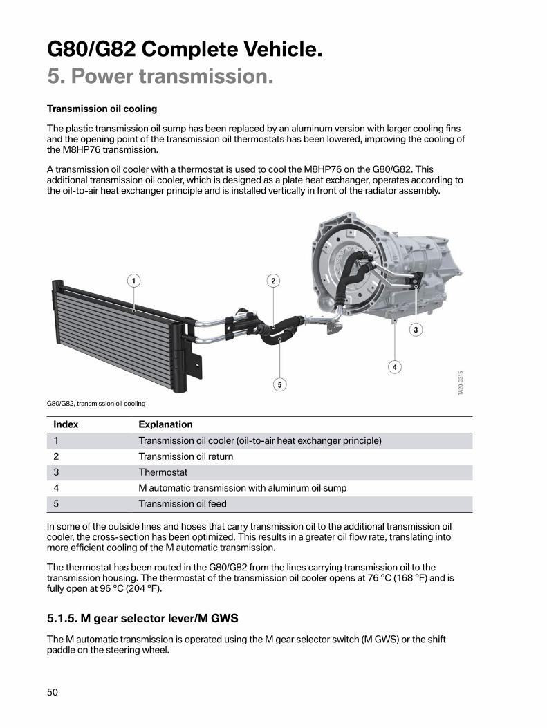
G80/G82�Complete�Vehicle.5.�Power�transmission.
50
Transmission�oil�cooling
The�plastic�transmission�oil�sump�has�been�replaced�by�an�aluminum�version�with�larger�cooling�finsand�the�opening�point�of�the�transmission�oil�thermostats�has�been�lowered,�improving�the�cooling�ofthe�M8HP76�transmission.
A�transmission�oil�cooler�with�a�thermostat�is�used�to�cool�the�M8HP76�on�the�G80/G82.�Thisadditional�transmission�oil�cooler,�which�is�designed�as�a�plate�heat�exchanger,�operates�according�tothe�oil-to-air�heat�exchanger�principle�and�is�installed�vertically�in�front�of�the�radiator�assembly.
G80/G82,�transmission�oil�cooling
Index Explanation1 Transmission�oil�cooler�(oil-to-air�heat�exchanger�principle)2 Transmission�oil�return3 Thermostat4 M�automatic�transmission�with�aluminum�oil�sump5 Transmission�oil�feed
In�some�of�the�outside�lines�and�hoses�that�carry�transmission�oil�to�the�additional�transmission�oilcooler,�the�cross-section�has�been�optimized.�This�results�in�a�greater�oil�flow�rate,�translating�intomore�efficient�cooling�of�the�M�automatic�transmission.
The�thermostat�has�been�routed�in�the�G80/G82�from�the�lines�carrying�transmission�oil�to�thetransmission�housing.�The�thermostat�of�the�transmission�oil�cooler�opens�at�76�°C�(168�°F)�and�isfully�open�at�96�°C�(204�°F).
5.1.5.�M�gear�selector�lever/M�GWSThe�M�automatic�transmission�is�operated�using�the�M�gear�selector�switch�(M�GWS)�or�the�shiftpaddle�on�the�steering�wheel.

G80/G82�Complete�Vehicle.5.�Power�transmission.
51
The�M-specific�shift�pattern,�as�used�for�the�M�double-clutch�transmissions,�was�retained�for�the�Mgear�selector�switch.
G80/G82,�M�gear�selector�switch�(example�of�BMW�M4�Competition)
Index Explanation1 Drivelogic�button2 Parking�lock�button3 Gear�display�(with�M-specific�shift�pattern)
In�terms�of�design�and�function,�the�M�gear�selector�switch�(M�GWS)�has�been�adopted�from�the�F95/F96�and�comprises:
• At�the�gear�selector�switch�-�base�made�from�Zamak�alloy.• Handle�covered�with�nappa�leather�with�the�M�embossing.• Contrast�stitching�with�the�BMW�M�colors.
It�is�possible�to�choose�and�change�between�an�automatic�"D�mode"�and�a�sequential�"Manualmode".�In�each�mode�there�are�3�driving�programs,�which�can�be�selected�and�activated�using�the"Drivelogic�switch".
Drivelogic
A�rocker�switch�is�used�on�the�G80/G82�for�changing�the�transmission�mode�up�or�down.
After�each�change�between�manual�mode�and�Drive�mode,�the�last�selected�driving�program�is�active.
After�each�engine�start�driving�program�1�is�active�in�Drive�mode.
D�mode/Drive�mode
G80/G82�Complete�Vehicle.5.�Power�transmission.
52
Automated�mode,�all�the�forward�gears�are�automatically�shifted.�Kickdown�is�triggered�by�depressingthe�accelerator�pedal�beyond�the�resistance�point.
Three�driving�programs�are�available�for�selection:
1:�Efficient�driving�-�Comfort�shifting�time
2:�Fast�driving�-�Sport�shifting�time
3:�Sporty�driving�-�Sport�Plus�shifting�time.
Manual�mode/sequential�mode
The�gears�can�be�manually�shifted�by�means�of�shift�paddles�on�the�steering�wheel�"+"�or�"–"�orthe�gear�selector�switch�"forward"�and�"back"�at�the�matching�driving�speed�and�engine�speed.The�selected�gear�is�maintained�even�when�the�engine�speed�limitation�is�reached,�but�an�automaticdownshift�is�performed�when�the�vehicle�drops�below�the�gear-specific�minimum�driving�speed.
When�the�manual�mode�is�selected�for�the�first�time�after�terminal�change�(engine�restart),�the�lastDrivelogic�stage�used�is�active.
Three�driving�programs�are�also�available�here�for�selection:
1:�Comfortable,�smooth�gearshifts�in�all�driving�conditions
2:�Sporty,�fast�gearshifts,�light�gearshift�jolts�permitted�at�higher�engine�loads�and�speeds
3:�Maximum�sporty�shift�speed�and�gearshifts�and�the�prerequisite�for�activation�of�Launch�Control
To�use�the�highest,�i.e.�the�third�driving�program,�M�DSCi�does�not�have�to�be�activated.
5.1.6.�Automatic�transmission�Launch�Control
During�the�first�3100�mile�run-in�distance,�the�Launch�Control�should�generally�not�be�used.
The�Launch�Control�is�active�from�the�factory.�The�activation�of�Launch�Control�is�not�restricted�to�the1200�mile�running-in�check.
Premature�wear�occurs�as�a�result�of�the�high�load�on�the�vehicle�components�when�using�LaunchControl.
Launch�Control
Function:�Launch�Control�enables�optimal�acceleration�when�driving�off�on�a�non-skid�roadway.

G80/G82�Complete�Vehicle.5.�Power�transmission.
53
Sequence Precondition/Action1. The�vehicle�must�be�stationary,�the�engine�running�and�at�operating
temperature�(approximately�6�mile�warm-up�journey).2. The�steering�angle�at�the�steering�wheel�must�not�be�greater�than�30°.3. M�Dynamic�Stability�Control�integrated�(M�DSCi)�is�deactivated.�(4WD)4. The�manual�mode�and�the�third�Drivelogic�driving�program�are�selected.5. The�brake�pedal�is�gently�pressed�with�the�left�foot�and�held.6. The�accelerator�pedal�is�depressed�fully�and�held�in�this�position.7. An�optimum�engine�speed�for�pulling�away�is�adjusted.8. A�Check�Control�message�is�issued�-�"Launch�Control�is�being�prepared"�(if
not,�check�notes�and�steps�1-5).9. A�Check�Control�message�is�issued�-�"Launch�Control�Active".10. The�left�foot�is�taken�off�the�brake�pedal�within�5�seconds.
Effect
• Launch�Control�automatically�shifts�up�using�the�shortest�possible�gearshift�times�andperformance-optimized�shift�points�as�long�as�the�customer�keeps�the�accelerator�pedal�fullydepressed.
• The�Check�Control�message�"Launch�Control�Active"�in�the�instrument�cluster�remains�active.
The�optimal�slip-controlled�Launch�Control�is�based�on�Michelin�Pilot�Sport�4S�and�Michelin�PilotSport�Cup�2�tires�at�operating�temperature.
A�renewed�Launch�Control�start�is�possible�as�long�as�the�transmission�oil�temperature�satisfies�theprerequisites�for�this.
Automatic�deactivation
• The�customer�releases�(even�if�only�briefly)�the�accelerator�pedal�full�load�range�duringacceleration.
A�manual�intervention�in�the�automatic�upshift,�for�example�via�the�shift�paddles�on�the�steering�wheelor�the�gear�selector�switch,�does�not�interrupt�the�Launch�Control�process.
If�one�of�these�preheating/precooling�conditions�is�breached,�it�is�not�possible�to�activate�the�LaunchControl.
Also�at�excessive�transmission�oil�temperature�(e.g.�repeat�Launch�Control�or�race-like�start),�activationis�blocked�until�an�acceptable�temperature�threshold�is�reached.
The�Check�Control�message�"Launch�Control�Active"�goes�out�with�every�deactivation�and�theautomatic�forced�upshift�is�cancelled.

G80/G82�Complete�Vehicle.5.�Power�transmission.
54
Premature�wear�occurs�as�a�result�of�the�high�load�of�the�vehicle�with�use�of�the�launch�control.
5.1.7.�Emergency�gearbox�release
A�mechanical�emergency�transmission�release�is�available�and�can�be�accessed�through�the�vehicleunderbody.�In�addition,�an�electronic�emergency�gearbox�release�is�implemented�as�it�is�in�automatictransmissions�of�the�BMW�AG�vehicles.�For�towing�away,�please�observe�the�information�in�theOwner's�Manual�of�the�vehicle.
Release�is�possible�if�the�starter�motor�can�crank�the�engine.�Apply�the�parking�brake�before�manualrelease�of�the�parking�lock�to�prevent�the�vehicle�from�rolling.
Sequence Precondition/Action1. Engage�selector�lever�position�N.2. Press�and�hold�the�brake.3. Press�the�start/stop�button�(the�starter�motor�must�start�up�audibly).4. Keep�the�start/stop�button�pressed.5. With�your�free�hand,�press�the�selector�lever�into�selector�lever�position�N�and
keep�it�there�until�selector�lever�position�N�appears�in�the�instrument�cluster.6. A�CC�message�is�displayed�in�the�KOMBI�and�in�the�CID.7. Release�the�start/stop�button�and�the�selector�lever.8. Release�the�brake�as�soon�as�the�starter�motor�stops.
Maneuver�the�vehicle�out�of�the�danger�area�and�then�secure�to�prevent�it�from�rolling.�Furtherinformation�can�be�found�in�the�Owner's�Manual�for�the�vehicle.
5.1.8.�Service�information
Transmission�oil�circuit
For�work�required�on�the�oil�circuit�of�the�automatic�transmission,�for�example�after�an�accident,�or�ifthe�oil�circuit�has�to�be�opened�owing�to�a�repair,�there�must�be�maximum�cleanliness.�They�include:
• Optimal�cleaning�of�the�outer�oil�circuit�areas�before�disassembly�of�the�components�oropening�the�oil�circuit.
• Immediate�closure�of�openings�and�lines�after�disassembly�without�delay�and�using�cleanoriginal�plugs.�Do�not�use�unsealed�components�or�replacement�parts�of�the�oil�circuit�withoutchecking�for�cleanliness�and�where�possible�competent�repair.
• The�work�bay�in�which�an�automatic�transmission�is�opened�must�be�extremely�clean�andsecured�against�dirt�contamination,�also�during�work�interruptions.�For�example�by�sufficientlyclean�and�lint-free�cover.

G80/G82�Complete�Vehicle.5.�Power�transmission.
55
Lifetime�oil�filling
Currently,�as�with�other�M�vehicles�with�M�automatic�transmission,�for�the�G80/G82�with�M�automatictransmission�a�transmission�oil�change�is�not�scheduled�at�1200�miles�(running-in�check)�or�with�everythird�engine�oil�change.
Current�transmission�oil�recommendations�and�capacities�can�be�found�in�the�current�documentationof�the�BMW�workshop�information�system.
5.2.�M�xDrive"High-performance�driving�dynamics�on�the�one�hand�and�the�everyday�usability�on�the�other"�ishow�we�could�describe�the�typical�M�concept�approach�in�which�the�individual�drivetrain�componentsare�perfectly�matched�with�the�M�xDrive�system.�That�enables�the�new�BMW�M3�and�the�BMW�M4Coupe�to�have�the�same�familiar�precise�sports�handling�whether�being�driven�on�the�race�track�or�thepublic�road.�In�addition,�they�are�also�a�delight�to�drive�even�in�unpleasant�weather�conditions�suchas�rain�and�snow�or�off�road�thanks�to�noticeable�extra�traction�and�controllability�right�up�to�the�limitsof�handling�stability.�The�agile�rear-oriented�design�is�achieved�by�allowing�the�M�xDrive�to�bring�thefront�axle�to�bear�only�when�the�rear�wheels�have�reached�their�limits�and�additional�traction�force�isrequired.�Even�when�adopting�a�very�vigorous�driving�style�using�a�lot�of�power,�the�new�BMW�M3�andthe�BMW�M4�Coupe�with�M�xDrive�show�themselves�to�be�predictable�and�effortless�to�control�for�thedriver,�so�that�the�outstanding�performance�of�the�vehicles�can�be�experienced�even�more�intensely.
G82,�system�overview,�M�xDrive

G80/G82�Complete�Vehicle.5.�Power�transmission.
56
Index Explanation1 M�Dynamic�Stability�Control�integrated�(M�DSCi)2 Front�output�shafts,�right3 Body�Domain�Controller�(BDC)4 Advanced�Crash�Safety�Module�(ACSM)5 Control�unit,�regulated�M�rear�axle�differential�lock�(M�GHAS)6 Rear�output�shafts,�right7 M�rear�axle�differential�lock8 Rear�output�shafts,�left9 Prop�shaft10 M�transfer�box�(M�VTG)11 Front�propeller�shaft12 Front�axle�differential13 Front�output�shafts,�leftFlexRay FlexRay�bus
5.2.1.�M�transfer�box�(M�VTG)The�M�xDrive�used�for�the�G80/G82�is�based�on�the�all-wheel�drive�of�the�G12�with�the�ATC13�transferbox�and�has�been�adopted�from�the�F97/F98.
The�torque�generated�by�the�engine�is�stepped�up�in�the�automatic�transmission�and�is�suppliedvia�the�transmission�output�shaft�to�the�transfer�box.�The�transfer�box�forming�the�next�stage�in�thedrivetrain�has�the�task�of�varying�the�torque�distribution�between�the�front�and�rear�wheels�across�thefull�range�from�0:100%�to�100:0%�as�demanded�by�the�driving�situation.�Since�a�rigid�connection�ofthe�rear�axle�with�the�front�axle�is�not�possible�due�to�possible�differences�in�the�wheel�speeds,�thereis�a�multidisc�clutch�inside�the�transfer�box.�The�multidisc�clutch�performs�the�task�of�variable�torquedistribution�between�the�two�drive�axles.
6-finger�oil�distributor
For�the�M�transfer�box�(M�VTG),�a�new�oil�distributor�is�used�in�the�G80/G82�in�the�disc�set�of�themultidisc�clutch.�The�new�oil�distributor�is�a�so-called�6-finger�oil�distributor�with�21�oil�outlet�borescompared�to�the�3-finger�oil�distributor�with�9�oil�outlet�bores�of�the�predecessor�generation�of�theATC13�with�the�M�transfer�box�(M�VTG).�Through�additional�input�of�cool�transmission�oil�by�the6-finger�oil�distributor�to�the�disc�set,�the�potential�of�the�M�xDrive�in�the�G80/G82�can�be�furtherimproved.
Due�to�the�permanent�distribution�of�the�drive�torques�between�front�axle�and�rear�axle�with�an�agileand�sporty�driving�style�and�the�arising�influence�of�heat�on�the�multidisc�clutch,�in�the�past�theinfluence�of�heat�on�the�clutch�had�to�be�reduced�in�order�to�protect�the�components.�This�is�doneby�closing�the�multidisc�clutch�in�order�to�reduce�friction�in�the�disc�set.�Closing�the�multidisc�clutch

G80/G82�Complete�Vehicle.5.�Power�transmission.
57
causes�a�distribution�of�the�drive�torque�to�the�front�axle,�which�in�turn�brings�about�an�increasein�driving�safety,�as�it�is�generally�easier�for�the�customer�to�control�understeering�vehicles�thanoversteering�vehicles.
With�the�use�of�the�6-finger�oil�distributor�it�is�now�possible�to�insert�transmission�oil�evenly�in�anaxial�movement�to�the�multidisc�clutch�in�order�to�reduce�the�influence�of�heat.�This�means�that�themultidisc�clutch�can�maintain�the�torque�distribution�between�rear�axle�and�front�axle�without�having�toreduce�the�typical�M�driving�pleasure�of�a�vehicle�oriented�at�the�rear-wheel�drive�in�conjunction�withthe�M�xDrive.
Furthermore,�the�advantages�of�the�6-finger�oil�distributor�are�also�assisted�by�the�actuator�wheel�sliplimitation�ARBx�for�the�M�all-wheel�drive.�Further�information�can�be�found�in�the�chapter�"ActuatorWheel�Slip�Limitation�ARB".
The�following�customer�benefits�arise�from�the�combination�of�a�6-finger�oil�distributor�in�conjunctionwith�the�actuator�wheel�slip�limitation�ARBx:
• Improvement�of�the�temperature�difference�in�the�multidisc�clutch,�therefore�bettercomponent�protection.
• Better�heat�dissipation,�as�a�result�a�higher�availability�of�the�M�xDrive�benefits�in�relation�topermanent�drive�torque�distribution�in�agile�driving�situations.
• Lower�temperature�level�of�the�transmission�oil�for�equal�torque�potential�possible,�as�a�resultlower�transmission�oil�damage/aging.
• Improved�cooling�effect,�thus�approximately�2x�faster�cooling�phases�of�the�multidisc�clutchpossible.
• Optimal�interaction�with�the�actuator�wheel�slip�limitation�ARBx,�as�a�result�there�is�an�evenmore�sensitive,�agile�M�xDrive�in�the�G80/G82�for�the�customer.
General�information�on�BMW�xDrive�can�be�found�in�the�reference�manual�"ST1501�G12�Powertrain".

G80/G82�Complete�Vehicle.5.�Power�transmission.
58
5.2.2.�M�VTG�system�wiring�diagram
G80/G82,�M�transfer�box�system�wiring�diagram
Index Explanation1 M�Dynamic�Stability�Control�integrated�(M�DSCi)2 M�transfer�box�(M�VTG)3 Power�distribution�box,�front�right4 Body�Domain�Controller�(BDC)5 Crash�Safety�Module�(ACSM)6 Head�Unit�High�3�(HU-H�3)7 Central�information�display�(CID)
5.2.3.�Service�information
• The�vehicle�must�not�be�driven�when�the�front�propeller�shaft�has�been�removed.• When�carrying�out�work�on�a�brake�test�stand,�it�is�not�necessary�to�take�into�account�any�all-
wheel�drive-specific�points.

G80/G82�Complete�Vehicle.5.�Power�transmission.
59
(Roller�mode�for�testing�the�brake�system�is�detected�automatically.)• The�vehicle�must�not�be�towed�if�only�one�axle�is�raised.• The�oil�filling�of�the�transfer�box�is�designed�for�the�entire�unit�service�life.
However,�a�fault�code�entry�with�an�oil�change�recommendation�for�the�transfer�box�oil�isstored�when�a�mileage�of�93,000�miles�is�exceeded.When�refilling�the�transfer�box�oil,�it�is�necessary�to�move�the�oil�partition�to�the�open�positionusing�the�diagnosis�system�ISTA.
• Various�test�plans�are�available�in�the�BMW�diagnosis�system�ISTA�for�Service.
The�tire�tread�depth�as�well�as�the�tire�manufacturer�should�be�the�same�on�the�front�and�rear�axles�ifpossible�in�order�to�ensure�proper�functioning�of�the�xDrive.�It�is�also�advisable�to�only�use�tires�thathave�been�approved�or�recommended�by�BMW�M.
5.2.4.�Lifetime�oil�fillingThe�oil�filling�of�the�transfer�box�is�designed�for�the�entire�unit�service�life.�This�corresponds�to�amileage�of�approximately�93,000�miles.�A�fault�code�entry�with�an�oil�change�recommendation�for�thetransfer�box�is�stored�when�this�mileage�is�exceeded.
The�transfer�box�does�not�have�an�oil�drain�plug.�The�oil�must�be�removed�using�an�extractor�unit.
The�new�transfer�box�oil�can�be�filled�using�an�oil�filler�plug.
In�order�to�ensure�that�the�entire�oil�filling�has�been�exchanged,�the�oil�partition�must�remain�open�forthe�duration�of�extraction�and�filling.
The�Service�employee�can�move�the�oil�partition�to�the�open�position�by�means�of�the�“Servicefunction�>�Transfer�box�VTG�>�Oil�change”�in�the�BMW�diagnosis�system�ISTA.
Current�transfer�box�oil�recommendations�and�capacities�can�be�found�in�the�current�documentation�ofthe�BMW�workshop�information�systems.
5.3.�Differential
5.3.1.�Front�axle�differentialThe�front�axle�transmission�VAG�170�AL�in�the�size�VAG�170�(crown�wheel��170 mm),�which�is�knownfrom�the�G07,�is�used.�This�front�axle�transmission�is�also�used�in�the�G20/G22.
The�gear�ratio�of�the�VAG�170�AL�is�3.153:1,�it�weighs�29.1 lbs.

G80/G82�Complete�Vehicle.5.�Power�transmission.
60
5.3.2.�Rear�axle�final�driveThe�familiar�active�M�Differential�is�used�in�the�G80/G82�as�a�rear�axle�differential.�This�electronically/electromechanically�controlled�rear�axle�differential�lock�has�been�developed�especially�for�the�F10�M5and�is�also�used�in�the�G80/G82.�The�electronically/electromechanically�controlled�rear�axle�differentiallock�of�the�G80/G82�is�based�on�a�derivation�from�the�F97/F98.
The�active�M�differential�has�been�reworked�for�the�G80/G82,�which�specifically�involved�adapting�therear�axle�differential�housing�to�the�rear�axle�supports�of�the�G80/G82.
The�M�rear�axle�differential,�size�HAG�225�M�(crown�wheel��225 mm),�is�used�with�a�M�rear�axledifferential�lock.�The�system�designation�is�"regulated�M�rear�axle�differential�lock"�and�the�control�unitdesignation�is�M�GHAS�(German�acronym�for�M�geregelte�Hinterachsgetriebesperre).
The�gear�ratio�of�the�HAG�225�is�3.153:1�with�the�automatic�transmission.
The�gear�ratio�of�the�HAG�225�is�3.462:1�with�the�manual�transmission.
This�M�rear�axle�differential�II�can�be�recognized�by�an�aluminum�oil�sump�mounted�from�below�and�anelectric�motor�which�is�visible�from�the�outside.
The�HAG�225�weighs�94.7�lbs.
Further�information�about�the�active�M�differential�can�be�found�in�the�reference�manual�"ST1907�F97/F98�Complete�Vehicle".
Current�axle�transmission�oil�recommendations�and�filling�capacities�can�be�found�in�the�currentdocumentation�of�the�BMW�workshop�information�systems.
5.3.3.�Service�information
• If�the�M�GHAS�control�unit�is�exchanged,�coding�(activation�of�a�vehicle-related�characteristiccurve)�and�then�initial�calibration�are�necessary,�after�which�the�fault�memory�must�be�deleted.
• After�the�replacement�of�the�entire�M�rear�axle�differential�a�calibration�must�be�performed�andthen�the�fault�memory�must�be�deleted.
• For�a�replacement�of�the�electric�motor,�electric�motor�plus�intermediate�gear�or�oiltemperature�sensor,�only�the�fault�memory�must�be�deleted.
The�final�drive�oil�is�currently�replaced�at�1200�miles�(running-in�check)�and�at�every�third�engine�oilchange.
Current�rear�axle�differential�oil�recommendations�and�capacities�can�be�found�in�the�currentdocumentation�of�the�BMW�workshop�information�systems.

G80/G82�Complete�Vehicle.5.�Power�transmission.
61
If,�due�to�a�fault,�the�M�GHAS�lock�function�is�switched�off�or�fails,�a�locked�differential�is�automaticallyopened�as�the�lock�function�is�not�self-locking.�The�customer�is�warned/informed�and�the�followingeffects�can�be�expected:
1.�Deterioration�of�traction�with�dynamic�driving�style�and�low�coefficients�of�friction,�particularly�withdifferent�coefficients�of�friction,�left/right.
2.�Possible�deterioration�of�stability�in�dynamic�driving�situations.
If�the�driver�drives�on�a�race�track�for�the�first�time�at�high�outside�temperatures�>�35 °C�(95�°F),�it�canresult�in�a�warning�message�with�regard�to�excess�temperature�in�the�rear�axle�differential.�The�reasonfor�this�is�the�behavior�of�the�rear�axle�differential�during�run-in.�After�a�sufficient�run-in�distance,�whichmay�vary�depending�on�the�load,�the�rear�axle�differential�temperatures�(in�the�rear�axle�differential�oiland�in�the�disc�set)�drop�to�a�lower�level�so�that�a�CC�message�no�longer�appears.
For�necessary�servicing�and�further�guidance�about�driving�on�the�race�track,�the�current�informationand�specifications�in�the�documents�in�the�Integrated�Service�Technical�Application�(ISTA)�must�beobserved�in�each�case.
5.4.�Propeller�shafts�and�output�shafts
5.4.1.�Front�propeller�shaftThe�propeller�shaft�at�the�front�has�been�adopted�from�the�F90,�adapted�to�the�higher�rotationalspeeds�and�in�its�diameter�from�40 mm�in�the�F90�to�48 mm�in�the�G80/G82.
5.4.2.�Rear�propeller�shaftThe�previously�used�crash�element�of�the�propeller�shaft�at�the�rear�can�no�longer�be�used�due�to�thereduction�of�the�diameter�of�the�propeller�shaft.�Therefore,�a�patented�BMW�new�development,�the�so-called�CSS-M�(Crash�Slip�System-M�GmbH),�is�being�introduced�for�the�G80/G82.

G80/G82�Complete�Vehicle.5.�Power�transmission.
62
G80/G82,�CCS-M
Index Explanation1 Pipe�adapter2 Outer�knurl3 Support�ring4 Crash�adapter
The�outer�knurl�of�the�crash�adapter�establishes�the�connection�to�the�pipe�adapter,�which�isscrewed�to�the�transmission�via�the�flexible�disc.�The�support�ring�provides�additional�support�forthe�connection�between�pipe�adapter�and�crash�adapter.�In�the�event�of�a�crash,�the�pipe�adapter�ispushed�from�the�support�ring�in�an�axial�direction�and�diverted�to�the�back�via�the�crash�adapter,�thefree�space�is�used�for�the�drive�unit�comprising�engine�and�transmission�for�the�necessary�crumplezone�in�order�to�dissipate�the�crash�energy.
After�an�accident�the�rear�propeller�shaft�must�be�checked�for�impact�or�activation�of�the�CSS-M.
For�necessary�service�work�the�current�information�and�specifications�in�the�documents�in�theIntegrated�Service�Technical�Application�(ISTA)�must�be�observed�in�each�case.
The�connection�of�the�propeller�shaft�and�the�rear�axle�differential�via�the�longitudinal�splines�isbonded�with�adhesive�in�the�factory�using�a�BMW�patented�microcapsule�and�screwed�using�therecessed�nut�in�order�to�avoid�load�change�noises.
The�repair�instructions�must�be�observed�when�releasing�this�connection�and�screwing�the�propellershaft�to�the�rear�axle�differential�again.

G80/G82�Complete�Vehicle.5.�Power�transmission.
63
It�is�important�to�follow�the�procedures�in�the�current�repair�instructions�in�ISTA�regarding�inserted�andscrewed�propeller�shafts�on�the�rear�axle�differential.
For�necessary�service�work�the�current�information�and�specifications�in�the�documents�in�theIntegrated�Service�Technical�Application�(ISTA)�must�be�observed�in�each�case.
Furthermore,�the�length�of�the�front�section�is�adapted�to�the�respective�drive�concept,�either�for�theall-wheel�drive�or�rear-wheel�drive.
The�maximum�permissible�deflection�angle�of�the�propeller�shaft�must�not�be�exceeded�when�workingon�the�propeller�shaft�center�bearing.
For�necessary�service�work�the�current�information�and�specifications�in�the�documents�in�theIntegrated�Service�Technical�Application�(ISTA)�must�be�observed�in�each�case.
5.4.3.�Front�output�shaftsThe�front�output�shafts�have�been�adopted�from�the�F90�and�adapted�to�the�G80/G82.
5.4.4.�Rear�output�shaftsThe�rear�output�shafts�with�the�new�VL3�joint�system�have�been�adopted�from�the�F90�and�adapted�tothe�G80/G82.�The�design�of�the�left�output�shaft�is�different�to�the�design�of�the�right�output�shaft�inorder�to�reduce�the�tramp�tendency�with�the�rear-wheel�drive.
Tramp�tendency�with�the�rear-wheel�drive
Specially�in�vehicles�with�UHP�(Ultra-High-Performance)�tires�with�hard�rubber�compounds�or�weatherconditions,�which�cause�this�(e.g.�in�winter�with�extremely�cold�tires),�a�so-called�tramp�of�the�vehicleat�the�rear�axle�may�occur�in�unfavorable�starting�conditions�in�vehicles�with�rear-wheel�drive.�Thesimultaneous�lifting�of�the�tire�contact�areas�of�the�left�and�right�drive�wheels�from�the�ground�is�calleda�tramp,�which�causes�a�high�resonant�oscillation�in�the�rear�area�of�the�vehicle.�This�resonance�isconsidered�annoying�and�uncomfortable�by�the�customer�and�also�has�a�negative�impact�in�relation�tothe�best�possible�traction�when�driving�off.
The�tramp�tendency�in�the�G80/G82�can�be�reduced�with�the�use�of�a�short�output�shaft�on�the�leftwhich�has�a�bigger�diameter�and�is�25 %�stiffer.�With�the�property�that�the�left�output�shaft�is�stifferand�shorter�than�the�right�output�shaft,�the�left�drive�wheel�enters�a�resonant�oscillation�when�drivingoff�first�by�the�lifting�of�the�tire�contact�area.�The�right�drive�wheel�with�the�lighter�and�longer�outputshaft�follows�now�with�the�entering�into�a�resonant�oscillation�with�a�time�delay.�Due�to�this�time�delayof�the�resonant�oscillations�of�left�and�right�drive�wheels,�the�resonant�oscillations�cancel�each�otherout�at�the�drive�wheels�and�the�tramp�tendency�is�thus�reduced.
With�the�additional�use�of�the�actuator�wheel�slip�limitation�ARB�and�the�regulated�rear�axle�differentiallock�at�the�rear�axle,�the�following�customer�benefits�arise�for�the�G80/G82:

G80/G82�Complete�Vehicle.5.�Power�transmission.
64
• Best�possible�traction�at�the�drive�wheels.• No�annoying�drive�influences�on�the�vehicle.
Further�information�can�be�found�in�the�chapter�"Actuator�Wheel�Slip�Limitation�ARB".

G80/G82�Complete�Vehicle.6.�Chassis�and�suspension.
65
G82,�chassis�and�suspension,�complete
The�chassis�and�suspension�is�based�on�the�technology�of�the�G2x�and�the�F9x,�whereby�almost�allcomponents�are�again�new�and�specific�to�M�or�have�been�adapted.
Designation Unit E9x�M3 F80/F82–M3/M4Coupe
G80/G82–M3/M4�Coupe
Wheelbase/TurningcircleTurning�circle�of�rear-wheel�driveTurning�circle�of�all-wheel�drive
[mm][m][m]
276111.7
281212.2
285712.212.67*
Front�track�width [mm] 1540 1579 1617Rear�track�width [mm] 1539 1603 1605Front�axle M�two-joint
spring-strutfront�axle
M�two-jointspring-strut
front�axle
M�two-joint�spring-strutfront�axle

G80/G82�Complete�Vehicle.6.�Chassis�and�suspension.
66
Designation Unit E9x�M3 F80/F82–M3/M4Coupe
G80/G82–M3/M4�Coupe
Steering HydraulicM�rack-and-pinionsteeringwith�M
Servotronic
Electricalrack-and-pinionsteering(EPS)with�M
Servotronic
Electrical�rack-and-pinionsteering(EPS)with�M
Servotronic
Rear-wheel�drive
Four-wheel�drive
Average�overall�ratio 12.5 15
15.01 14.63Steering�wheel�turnsEnd�stop-end�stop
2.4 2.5 2.35
Rear�axle M�5-linkrear�axle
M�5-linkrear�axle
M�5-link�rear�axle
Axle�ratio�with�manual�transmissionAxle�ratio�with�automatic�transmission
3.154 3.462 3.4623.154
*Expected�values�with�M�xDrive
6.1.�Front�axleThe�front�axle�is�based�on�the�M�double-joint�spring-strut-type�front�axle�of�the�G2x.�All�componentsand�bearings�are�new�or�adapted�for�M-specific�use.
Two�different�front�axle�supports�are�used�for�the�all-wheel�drive�and�rear-wheel�drive.
As�an�M�all-wheel�drive�is�used�for�the�first�time�in�a�BMW�M3�and�BMW�M4�Coupe,�the�double-jointspring-strut-type�front�axle�including�front�axle�support�had�to�be�completely�revised�again�in�relationto�the�axle�geometry�for�use�in�the�all-wheel�drive�vehicle.
The�new�axle�geometry�of�the�front�axle�for�the�all-wheel�drive�with�the�steering�more�further�forward,the�adapted�anti-roll�bar,�as�well�as�tension�and�traction�strut�and�swivel�bearing,�combines�typical�Mdriving�dynamics�properties�with�reduced�drive�influences�on�the�steering.

G80/G82�Complete�Vehicle.6.�Chassis�and�suspension.
67
G82,�double-joint�spring-strut-type�front�axle�with�all-wheel�drive
Index Explanation1 M�front�axle�support2 M�anti-roll�bar�link3 M�spring�strut�with�support�bearing4 M�swivel�bearing5 M�wheel�bearing�unit�with�wheel�flange6 M�wishbone7 M�track�rod8 M�tension�strut9 M�anti-roll�bar10 M�Servotronic�(EPS)11 M�stiffening�plate
All�components�have�been�redesigned�for�the�increased�requirements.�Wheel�guidance�forcompression�and�steering�is�achieved�via�the�wishbone,�the�tension�strut,�the�spring�strut�and�thetrack�rod.

G80/G82�Complete�Vehicle.6.�Chassis�and�suspension.
68
In�order�to�guarantee�a�precise�wheel�guide�in�transverse�direction�of�vehicle,�the�power�transmissionis�achieved�from�the�swivel�bearing�to�the�front�axle�guide�via�ball�joints�with�no�play.�In�order�toalso�guarantee�this�in�a�longitudinal�direction,�the�chassis�and�suspension�forces�are�transmitted�inlongitudinal�direction�of�vehicle�via�specially�developed�elastomer�bearings�for�the�G80/G82�via�thetension�struts�to�the�front�axle�support.
A�lowered�roll�center,�as�well�as�increased�after-run�and�spread�values,�ensure�perfect�steeringresponse�with�good�comfort.�Toe�and�camber�values�have�been�optimized�and�together�with�the�tireshave�been�designed�for�maximum�transverse�dynamics.
The�M�front�axle�support�made�of�aluminum�(G2x;�steel)�is�typical�M�with�a�stiffening�plate�with�doublesill�connection,�thus�also�reinforcing�the�rigidity�of�the�front�end.
The�connection�between�the�spring�strut�and�the�swivel�bearing�was�realized�by�a�clamp�connectionsimilar�to�the�F8x.
6.1.1.�SteeringThe�steering�used�for�the�new�G80/G82�is�a�rack�and�pinion�steering�with�electrical�steering�wheelsupport�"M�Servotronic�based�on�EPS"�from�Thyssen�Krupp�Power�Steerings.
For�power�assistance�during�steering�an�electric�motor�is�housed�parallel�to�the�rack�at�the�steeringgear�housing,�the�power�transmission�is�achieved�via�a�ball�screw.
In�order�to�reduce�the�influence�of�heat�on�the�steering,�the�M�Electronic�Power�Steering�(M�EPS)�inthe�G80/G82�has�a�heat�shield,�which�is�installed�upstream�from�the�M�Electronic�Power�Steering�(MEPS).

G80/G82�Complete�Vehicle.6.�Chassis�and�suspension.
69
G80/G82�steering
Index Explanation1 M�steering�wheel2 Adjustable�steering�column3 Steering�column4 M�track�rod,�left5 M�Servotronic�(EPS)6 M�track�rod,�right
The�M�Servotronic�(EPS)�is�an�independent�development�for�the�BMW�M3�and�the�BMW�M4�Coupe.All�components�of�the�M�Servotronic�(EPS)�have�been�developed�specifically�for�the�BMW�M3�and�theBMW�M4�Coupe.�With�this�measure�the�development�of�the�steering�was�able�to�be�coordinated�to�thetypical�M�properties.�Special�attention�was�paid�here�to�the�typical�M�features:

G80/G82�Complete�Vehicle.6.�Chassis�and�suspension.
70
• Direct�steering�sensation.• Driving�condition�feedback.• Dynamic�driving�in�the�limit�range.
G80/G82�M�Servotronic�(EPS)
Index Explanation1 Reduction�gear2 Steering-torque�sensor3 Track�rod4 Control�unit,�M�Servotronic�(EPS)5 Electric�motor�with�rotor�position�sensor
The�ratio�of�the�M�Servotronic�(EPS)�has�also�been�adapted�to�the�BMW�M3�and�the�BMW�M4�Coupe,whereby�different�ratios�are�used�for�the�variable�ratio�of�the�rack�for�rear-wheel�drive�and�all-wheeldrive�due�to�the�different�front�axle�geometry.
Steering�gear�ratio,�rear-wheel�drive(C-factor)
Steering�gear�ratio,�all-wheel�drive(C-factor)
63/70/63�(mm/revolution) 69.3/78/71�(mm/revolution)

G80/G82�Complete�Vehicle.6.�Chassis�and�suspension.
71
6.1.2.�M�ServotronicThe�Servotronic�function�familiar�from�conventional�hydraulic�steering�systems�is�also�used�inthe�M�Servotronic�(EPS)�and�is�available�as�standard�in�the�G80/G82.�It�is�a�M�Servotronic,�whichfunctions�according�to�the�same�operating�principle�as�in�production�vehicles.�The�difference�in�the�MServotronic�of�the�G80/G82�is�that�this�can�be�selected�in�2�stages�(in�the�F8x�3-stages);�in�contrast�tothe�F8x�in�the�G80/G82�the�Servotronic�Settings�menu�is�accessed�in�the�central�information�display(CID)�via�a�SETUP�button�in�the�center�console.�The�driver�can�switch�between�"COMFORT"�and"SPORT"�via�the�SETUP�button.�The�program�selection�can�also�be�preconfigured�in�the�Head�UnitHigh�3�(HU-H�3)�and�selected�using�the�M1/M2�buttons�on�the�steering�wheel.�Here�the�correspondingcharacteristic�curve�is�activated�and�in�Sport�direction�the�power�steering�support�is�also�noticeablywithdrawn.
Program�description,�M�Servotronic:
• “COMFORT”:�Focus�on�light�and�comfortable�steering�torques�with�perfect�feedback�from�theroad�surface�at�the�same�time.
• "SPORT":�Greater�rise�in�the�steering�force�and�perceptibly�more�feedback�for�sporty�Mdynamic�driving,�both�for�every�day�use�and�at�the�dynamic�driving�limit.
6.1.3.�Steering�angle�sensorThe�information�on�the�steering�angle�in�the�G80/G82�is�not�recorded�by�the�Electronic�Power�Steering(EPS)�and�not�via�a�separate�sensor�on�the�steering�wheel�and�instead�is�computed�based�on�themotor�position�angle�of�the�EPS�motor�in�relation�to�the�steering�wheel.
The�EPS�delivers�the�position�of�the�rack�via�FlexRay�to�the�M�Dynamic�Stability�Control�integrated�(MDSCi).�During�this�process,�the�EPS�calculates�the�absolute�position�of�the�rack�based�on�the�currentmotor�position�of�the�EPS�motor�and�the�number�of�complete�revolutions�performed�by�the�motorstarting�from�the�zero�position�(straight-ahead�driving�position).
Taking�this�position�as�the�starting�point,�M�Dynamic�Stability�Control�integrated�(M�DSCi)�determinesthe�wheel-specific�steering�angle�among�other�things�using�the�stored�ratio�parameters�(rack�to�wheel-specific�steering�angle)�and�transmits�this�via�FlexRay.�This�wheel-specific�steering�angle�is�used�by�MDynamic�Stability�Control�integrated�(M�DSCi)�among�other�things�as�a�reference�variable�for�internalcontrol�functions.
In�cases�where�the�absolute�value�is�not�available�from�the�EPS�(loss�of�terminal�30,�flash�process),�theabsolute�value�is�determined�through�interaction�between�M�Dynamic�Stability�Control�integrated�(MDSCi)�and�EPS�using�an�adaptation�function�in�which�the�steering�wheel�is�turned�from�end�stop�toend�stop�(e.g.�straight-ahead�position�->�left�->�right�->�straight-ahead�position).

G80/G82�Complete�Vehicle.6.�Chassis�and�suspension.
72
6.1.4.�System�wiring�diagram,�M�Servotronic
G80/G82,�EPS�system�wiring�diagram
Index Explanation1 Digital�Motor�Electronics�(DME)2 M�Servotronic�(EPS)3 Power�distribution�box,�engine�compartment4 Power�distribution�box,�front5 Body�Domain�Controller�(BDC)6 Crash�Safety�Module�(ACSM)7 Steering�column�switch�cluster�(SZL)8 Instrument�cluster�(KOMBI)9 M�Dynamic�Stability�Control�integrated�(M�DSCi)
6.2.�Rear�axleThe�M�rear�axle�of�the�G80/G82�is�based�on�the�five-link�rear�axle�from�the�F8x�and�has�been�adaptedto�the�new�installation�space�and�load�requirements�in�the�G80/G82.

G80/G82�Complete�Vehicle.6.�Chassis�and�suspension.
73
G80/G82�five-link�rear�axle
Index Explanation1 M�wheel�bearing�unit�with�drive�flange2 M�control�arm3 M�trailing�arm4 M�camber�control�arm5 M�rear�axle�support6 M�wishbone7 M�track�control�arm8 M�wheel�carrier
The�M�wishbone,�M�wheel�carrier�and�the�M�wheel�bearing�units�have�been�developed�new�for�theG80/G82.�All�trailing�arms�and�also�the�wheel�carrier�are�manufactured�in�aluminum�forging�technology.This�design�reduces�the�unsprung�masses�of�the�components�responsible�for�wheel�guidance.

G80/G82�Complete�Vehicle.6.�Chassis�and�suspension.
74
G80/G82�five-link�arrangement�with�wheel�carrier
Index Explanation1 M�wheel�bearing�unit�with�drive�flange�(new�G80/G82)2 M�wheel�carrier�(new�G80/G82)3 M�control�arm�(adopted�from�F8x)4 M�track�control�arm�(adopted�from�F8x)5 M�wishbone�(new�G80/G82)6 M�rear�axle�support7 M�camber�control�arm�(adopted�from�F8x)8 M�trailing�arm�(adopted�from�F8x)
The�rear�axle�support�itself�is�made�from�steel�pipe�which�is�similar�to�a�steel�pipe�grid�frame.�Thisdesign�is�characterized�by�maximum�rigidity�and�minimal�weight.�The�M�rear�axle�support�is�fixed�to�thebody�without�a�bearing.�This�fixed�screw�connection�directly�to�the�body�ensures�an�optimized�wheelguide�and�thus�enhanced�directional�stability.�In�addition,�through�the�use�of�diagonal�struts�a�directtransmission�of�the�longitudinal�forces�applied�during�braking�to�the�body�structure�was�achieved.
Weight�savings�are�achieved�with�the�aluminum�spring�strut�and�the�anti-roll�bar�in�a�tubular�design.
The�design�of�the�rear�axle�was�created�in�close�cooperation�with�the�tires�which�were�also�speciallydeveloped�for�the�G80/G82.

G80/G82�Complete�Vehicle.6.�Chassis�and�suspension.
75
6.3.�Brakes�and�wheels/tires
6.3.1.�Brakes
G80/G82,�brake�system
Index Explanation1 M�Dynamic�Stability�Control�integrated�(M�DSCi)2 Brake�pedal3 Rear�single-piston�floating�caliper�with�actuator�for�the�electromechanical
parking�brake4 Rear�brake�disc5 Front�six-piston�fixed�caliper
M�Compound�brake
The�M�compound�brake�offers�even�greater�braking�power�than�the�Sport�brake�offered�in�the�G2x.�In�adirect�comparison�it�also�offers:

G80/G82�Complete�Vehicle.6.�Chassis�and�suspension.
76
• Reduction�in�the�vehicle�weight,�resulting�in�improved�agility�and�dynamics,�acceleratingcapability�and�reduced�consumption.
• Reduction�in�the�rotating�mass,�resulting�in�improved�accelerating�ability,�response�andhandling.
• Increased�fading�stability�and�greater�thermal�resistance.• Copper-free�brake�pads.• Perforated�disc�ring,�sports-style�look,�optimized�response�characteristics�in�the�wet.• Consistent�realization�of�intelligent�lightweight�construction.• Technology�transfer�from�M�sport.• Unique,�authentic�M�design.
Designation Unit F80/F82 G80/G82Front�brake 4�pistons,
fixed�caliper6�pistons,fixed�caliper
Brake�disc,�front [mm] 380�x�30 380�x�36Rear�brakes 2�pistons,
fixed�caliper1�piston,
floating�caliperBrake�disc [mm] 370�x�24 370�x�24Parking�brake mechanical electro-
mechanical
A�large-sized,�perforated�M�compound�brake�disc�combined�with�a�six-piston�fixed�caliper�fromBrembo�is�used�at�the�front�axle.�Irrespective�of�the�selected�vehicle�color,�all�brake�calipers�are�bluemetallic�in�color�with�the�M�logo.�The�colors�red�and�black�are�also�available�as�brake�caliper�colors�atthe�front�and�rear�in�order�to�customize�the�BMW�M3�and�the�BMW�M4�Coupe.
Front�brake,�M�Compound�brake

G80/G82�Complete�Vehicle.6.�Chassis�and�suspension.
77
A�large-sized,�perforated�M�Compound�brake�disc�combined�with�a�1-piston�floating�caliper�withelectromechanical�parking�brake�from�TRW�is�used�at�the�rear�axle,�which�corresponds�in�designand�function�to�the�AG�vehicles.�Irrespective�of�the�selected�vehicle�color,�all�brake�calipers�are�bluemetallic�in�color�with�the�M�logo.�The�colors�red�and�black�are�also�available�as�brake�caliper�colors�atthe�front�and�rear�in�order�to�customize�the�BMW�M3�and�the�BMW�M4�Coupe.
With�the�use�of�the�M�Compound�brake�system,�the�use�of�sport�brake�pads�(available�separately)�isrecommended�on�race�tracks.
For�necessary�information�on�spare�parts,�the�information�and�specifications�of�the�documents�in�theElectronic�Parts�Catalog�(EPC)�which�are�updated�daily�must�be�observed�in�each�case.
For�necessary�service�work�the�current�information�and�specifications�in�the�documents�in�theIntegrated�Service�Technical�Application�(ISTA)�must�be�observed�in�each�case.
In�vehicles�with�M�Compound�brake,�the�covers�of�the�brake�ventilation�duct�in�the�wheel�arches�at�thefront�left�and�right�must�be�removed�before�operation�on�the�race�track.
• Improved�cooling�of�the�M�Compound�brake�on�the�race�track�is�guaranteed�with�the�removalof�the�covers.
• The�wear�and�brake�fading�are�reduced�by�better�cooling�of�the�M�Compound�brake.
In�vehicles�with�M�Compound�brake,�reinstall�the�covers�of�the�brake�ventilation�duct�in�the�wheelarches�at�the�front�left�and�right�after�operation�on�the�race�track.
• The�covers�reduce�the�ingress�of�water�to�the�M�Compound�brake,�thus�improving�theresponse�characteristics�of�the�M�Compound�brake�in�wet�conditions.
• The�covers�have�an�impact�on�the�drag�coefficient,�and�thus�on�the�carbon�dioxide�emissions.
These�covers�must�always�be�installed�when�the�vehicle�is�used�on�a�public�road�(approval-related).
For�necessary�servicing�and�further�guidance�about�driving�on�the�race�track,�the�current�informationand�specifications�in�the�documents�in�the�Integrated�Service�Technical�Application�(ISTA)�must�beobserved�in�each�case.
M�carbon�ceramic�brakes
The�M�carbon�ceramic�brake�is�available�from�the�series�launch�of�the�new�G80/G82.�The�M�carbonceramic�brake�can�be�ordered�as�optional�equipment�SA�2NK.
The�M�Carbon�ceramic�brake�system�is�also�called�the�C/SiC�brake�system.
Depending�on�the�situation,�this�offers�a�further�increase�in�braking�power�as�compared�to�the�Mcompound�brake.�In�a�direct�comparison�it�also�offers:

G80/G82�Complete�Vehicle.6.�Chassis�and�suspension.
78
• Even�more�direct/spontaneous�use�of�brake�force.• Maximum�heat�resistance�even�with�continuous�sporty�operation.• Higher�fading�stability.• Copper-free�brake�pads.• Significantly�reduced�wear.• 15�lb�weight�reduction�of�rotating�wheel�masses.• Increased�suitability�for�winter�driving�conditions�thanks�to�corrosion�resistance.
Front�brake,�M�carbon�ceramic�brake
As�a�visible�distinguishing�feature�to�the�M�Compound�brake�system�the�brake�calipers�are�painted�ingold�with�a�colored�M�logo.
The�brake�discs�are�manufactured�by�Brembo�SGL�Carbon�Ceramic�Brakes�GmbH.
Designation Unit F80/F82 G80/G82Front�brake 6�pistons,
fixed�caliper6�pistons,fixed�caliper
Brake�disc,�front [mm] 400�x�38 400�x�38Rear�brakes 4�pistons,
fixed�caliper1�piston,
floating�caliperBrake�disc [mm] 380�x�28 380�x�28Holding�brake mechanical electro-
mechanical

G80/G82�Complete�Vehicle.6.�Chassis�and�suspension.
79
In�vehicles�with�M�carbon�ceramic�brake,�the�covers�of�the�brake�ventilation�duct�in�the�wheel�arches�atthe�front�left�and�right�must�be�removed�before�operation�on�the�race�track.
• Improved�cooling�of�the�M�carbon�ceramic�brake�on�the�race�track�is�guaranteed�with�theremoval�of�the�covers.
• The�wear�and�brake�fading�are�reduced�by�better�cooling�of�the�M�carbon�ceramic�brake.
In�vehicles�with�M�carbon�ceramic�brake,�reinstall�the�covers�of�the�brake�ventilation�duct�in�the�wheelarches�at�the�front�left�and�right�after�operation�on�the�race�track.
• The�covers�reduce�the�ingress�of�water�to�the�M�carbon�ceramic�brake,�thus�improving�theresponse�characteristics�of�the�M�carbon�ceramic�brake�in�wet�conditions.
• The�covers�have�an�impact�on�the�drag�coefficient,�and�thus�on�the�carbon�dioxide�emissions.
These�covers�must�always�be�installed�when�the�vehicle�is�used�on�a�public�road�(approval-related).
For�necessary�servicing�and�further�guidance�about�driving�on�the�race�track,�the�current�informationand�specifications�in�the�documents�in�the�Integrated�Service�Technical�Application�(ISTA)�must�beobserved�in�each�case.
Brake�noise
• Humming�of�the�BMW�M�compound�brake�disc�at�high�speeds.• Squeaking�brakes�shortly�before�coming�to�a�stop.• Hooting�in�the�event�of�wet,�cold�BMW�M�carbon�ceramic�brakes.• Ticking�noises�from�the�area�of�the�BMW�M�compound�brake�discs�when�hot.
Explain�to�the�customer�at�this�point�that�such�noises�occurring�temporarily�or�in�specific�situations�areinherent�in�the�design�and�do�not�represent�a�quality�problem.�They�are�a�consequence�of�the�specialperformance�of�the�brakes�and�do�not�pose�any�danger�or�risk�of�damage.
Point�out�that�the�customer�can�use�his/her�braking�technique�to�help�prevent�the�noises�occurringor�ensure�they�quickly�disappear�again.�For�example,�after�washing�the�vehicle�it�is�important�to�drythe�brakes�out�by�braking�(braking�a�few�times�from�31�mph�to�0�is�sufficient).�Or�that�the�brakes�canhave�a�tendency�to�squeak�if�they�go�through�long�periods�when�they�are�only�exposed�to�light�braking,which�is�why�braking�hard�a�few�times�can�help�out�(=�higher�brake�temperature).�After�driving�thevehicle�very�hard�and�subjecting�the�braking�system�to�high�loads�(high�brake�disc�temperatures)�thedriver�should�try�to�make�sure�that�the�brakes�are�able�to�cool�down�while�the�vehicle�is�moving�and�notto�keep�the�brakes�on�the�first�time�the�vehicle�comes�to�a�stop.�As�a�result�of�the�increased�materialtransfer�from�the�brake�pads�to�the�disc�after�very�hard�driving,�a�humming�noise�can�occur�whichdisappears�again�after�a�short�time.
Brake�dust

G80/G82�Complete�Vehicle.6.�Chassis�and�suspension.
80
Brake�dust�is�the�consequence�of�a�high-performance�brake�system.�The�BMW�M�models�are�high-performance�vehicles�which�are�designed�for�fast�and�dynamic�driving�and�embody�a�racing�pedigree.The�specially�designed�brakes�make�possible�the�high�braking�performance�required�by�the�vehicleand�in�so�doing�generate�larger�amounts�of�dust�due�to�the�greater�levels�of�friction.�The�brake�dusttells�the�customer�that�his/her�BMW�M�vehicle�has�been�driven�in�an�appropriate�manner.�What�isimportant�is�to�ensure�that�it�is�regularly�removed�by�washing�the�vehicle,�as�otherwise�it�will�eat�intothe�surface�of�the�wheel.
For�necessary�service�work�the�current�information�and�specifications�in�the�documents�in�theIntegrated�Service�Technical�Application�(ISTA)�must�be�observed�in�each�case.
6.3.2.�Wheels/Tires
G80/G82,�range�of�wheels
Index Explanation1 M�wheel�824M�double-spoke�Orbit�Grey2 M�wheel�825M�double-spoke�Bi-color3 M�wheel�825M�double-spoke�Orbit�Grey-Matte4 M�wheel�826M�double-spoke�Bi-color5 M�wheel�826M�double-spoke�Jet�Black
The�following�wheel/tire�combinations�are�offered:
1.Styling�824M
Manufacture Wheels/Tires Tiremanufacturer
Front9.5J�x�18H2�IS20
275/40�ZR18(103Y)�XLDouble�spoke
Orbit�greyin�high-gloss
Forged
Rear10.5J�x�19H2�IS20
285/35�ZR19(103Y)�XL
Yokohama�AdvanSport�V107,ContinentalSportContact�6

G80/G82�Complete�Vehicle.6.�Chassis�and�suspension.
81
2.Styling�825M
Manufacture Wheels/Tires Tiremanufacturer
Front9.5J�x�19H2�IS20
275/35�ZR19(100Y)�XL
Double�spokeBi-colordiamond
polished/milledin�high-gloss
Forged
Rear10.5J�x�20H2�IS20
285/30�ZR20(99Y)�XL
Yokohama�AdvanSport�V107,Pirelli�P�Zero,Michelin�PilotSport�4S
3.Styling�825M
Manufacture Wheels/Tires Tiremanufacturer
Front9.5J�x�19H2�IS20
275/35�ZR19(100Y)�XL
Double�spokeOrbit�greyRim�flangediamondpolishedin�matte
Forged
Rear10.5J�x�20H2�IS20
285/30�ZR20(99Y)�XL
Yokohama�AdvanSport�V107,Pirelli�P�Zero,Michelin�PilotSport�4S
4.Styling�826M
Manufacture Wheels/Tires Tiremanufacturer
Front9.5J�x�19H2�IS20
275/35�ZR19(100Y)�XL
Double�spokeBi-colordiamondpolishedspokes
in�high-gloss
Forged
Rear
10.5J�x�20H2�IS20
285/30�ZR20(99Y)�XL
Yokohama�AdvanSport�V107,Pirelli�P�Zero,Michelin�PilotSport�4S,Track:Pirelli�P
Zero�Corsa,MichelinPilotSport�Cup2
5.Styling�826M
Manufacture Wheels/Tires Tiremanufacturer
Front9.5J�x�19H2�IS20
275/35�ZR19(100Y)�XLDouble�spoke
Jet�BlackHigh-gloss
Forged
Rear
10.5J�x�20H2�IS20
285/30�ZR20(99Y)�XL
Yokohama�AdvanSport�V107,Pirelli�P�Zero,Michelin�PilotSport�4STrack:Pirelli�P
Zero�Corsa,MichelinPilotSport�Cup2
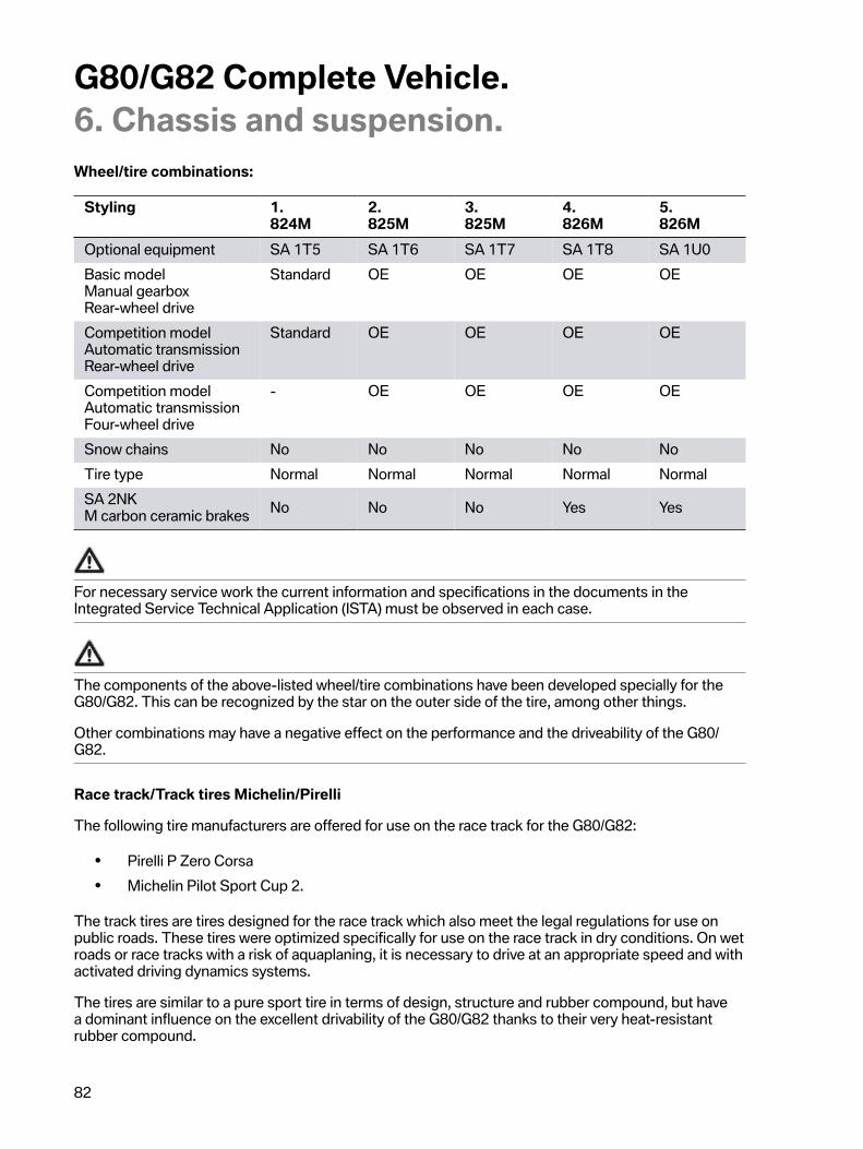
G80/G82�Complete�Vehicle.6.�Chassis�and�suspension.
82
Wheel/tire�combinations:
Styling 1.824M
2.825M
3.825M
4.826M
5.826M
Optional�equipment SA�1T5 SA�1T6 SA�1T7 SA�1T8 SA�1U0Basic�modelManual�gearboxRear-wheel�drive
Standard OE OE OE OE
Competition�modelAutomatic�transmissionRear-wheel�drive
Standard OE OE OE OE
Competition�modelAutomatic�transmissionFour-wheel�drive
- OE OE OE OE
Snow�chains No No No No NoTire�type Normal Normal Normal Normal NormalSA�2NKM�carbon�ceramic�brakes No No No Yes Yes
For�necessary�service�work�the�current�information�and�specifications�in�the�documents�in�theIntegrated�Service�Technical�Application�(ISTA)�must�be�observed�in�each�case.
The�components�of�the�above-listed�wheel/tire�combinations�have�been�developed�specially�for�theG80/G82.�This�can�be�recognized�by�the�star�on�the�outer�side�of�the�tire,�among�other�things.
Other�combinations�may�have�a�negative�effect�on�the�performance�and�the�driveability�of�the�G80/G82.
Race�track/Track�tires�Michelin/Pirelli
The�following�tire�manufacturers�are�offered�for�use�on�the�race�track�for�the�G80/G82:
• Pirelli�P�Zero�Corsa• Michelin�Pilot�Sport�Cup�2.
The�track�tires�are�tires�designed�for�the�race�track�which�also�meet�the�legal�regulations�for�use�onpublic�roads.�These�tires�were�optimized�specifically�for�use�on�the�race�track�in�dry�conditions.�On�wetroads�or�race�tracks�with�a�risk�of�aquaplaning,�it�is�necessary�to�drive�at�an�appropriate�speed�and�withactivated�driving�dynamics�systems.
The�tires�are�similar�to�a�pure�sport�tire�in�terms�of�design,�structure�and�rubber�compound,�but�havea�dominant�influence�on�the�excellent�drivability�of�the�G80/G82�thanks�to�their�very�heat-resistantrubber�compound.

G80/G82�Complete�Vehicle.6.�Chassis�and�suspension.
83
G80/G82,�Cup�tire�tread
The�tires�are�designed�for�maximum�dry�performance�and�offer�significantly�more�potential�forlongitudinal�and�lateral�acceleration�and�for�steering�precision�than�comparable�standard�tires.�Theyhave�an�asymmetrical�tread�pattern�with�a�high�positive�pattern�share�(large�contact�surface�=�fewrecesses).�Their�wet�performance�is�correspondingly�reduced.�The�customer�should�be�informedabout�this�by�an�additional�sheet�as�an�appendix�to�the�purchase�contract�when�purchasing�the�G80/G82.�The�tires�have�the�following�properties�and�thus�customer�benefits:
• High�tread�depth:�Improved�wet�grip�and�thus�later�aquaplaning�tendency.�This�meansgreater�safety�on�wet�roads.
• Two-component�technology:�Two�different�rubber�compounds�on�the�outer�side�andinside�of�the�tire�tread�surface.�The�tire�outer�side�consists�of�highly�linked�elastomers�whichoffer�optimum�grip�and�abrasion�protection�in�particularly�tight�corners.�The�tire�inner�sidecomprises�hard�elastomers�which�improve�steering�precision�and�offer�optimum�grip�on�wetroad�surfaces.
ATTENTION
• If�the�tires�are�not�used�for�an�extended�period,�it�is�recommended�to�remove�the�wheels�fromthe�vehicle�and�to�reduce�the�tire�pressure�to�half�the�usual�value.
• The�tires�should�be�stored�in�a�clean,�dry�and�dark�location�in�accordance�with�therecommendations�from�the�tire�manufacturer�and�at�temperatures�above�0 °C�(32�°F).
• The�use,�storage�or�handling�of�the�tires�at�ambient�temperatures�below�–10 °C�(14�°F)�shouldbe�avoided.�Elements�of�the�rubber�compound�may�be�damaged�under�these�conditions.�Thiswill�impair�the�performance�characteristics�of�the�tire�and�may�even�cause�cracks�or�breaks�inthe�tire�tread�which�make�further�use�of�the�tire�impossible.
• Never�use�a�tire�that�has�cracks,�breaks�or�other�damage�on�the�tire�tread�or�sidewalls.�In�caseof�doubt,�the�customer�should�consult�BMW�Service.
• In�the�case�of�intensive�race�track�use,�the�tires�or�tire�casing�may�become�damaged�afterextended�driving�and�frequent�driving�over�the�curbs.
• The�tires�must�be�checked�carefully�if�they�have�been�frequently�driven�over�curbs�or�thevehicle�has�left�the�track.�In�such�a�case,�it�is�necessary�to�remove�the�tire�from�the�wheel�inorder�to�inspect�both�the�outer�and�inner�sides�of�the�tire.
• A�visual�check�of�the�tires�must�be�performed�after�every�“run”�and�before�returning�to�thetrack.

G80/G82�Complete�Vehicle.6.�Chassis�and�suspension.
84
The�following�must�be�observed�before�intensive�race�track�use:
• Use�track�tires�recommended�for�use�on�the�race�track,�"Pirelli�P�Zero�Corsa"�or�"Michelin�Cup2".
• Always�check�the�condition�of�the�tires�for�wear�and�possible�damage.• Warm�up�the�tires�by�driving�moderately�for�a�few�laps.• The�optimal�tire�pressure�is�between�2.3 bar�(33 psi)�and�2.7 bar�(39 psi)�when�warm.�If�the
tire�pressure�for�use�on�the�race�track�falls�below�the�level�of�the�cold�tire�inflation�pressureapproved�for�use�on�public�roads,�a�filling�pressure�warning�can�be�avoided�in�the�electronictire�pressure�specification�by�selecting�"other�tires"�and�then�"Reset".
• Never�drive�with�a�tire�pressure�of�less�than�1.9�bar�(27.5�psi).
Cooling�laps
• Directly�following�the�intensive�race�track�use�the�vehicle�may�not�be�stopped�straight�away�foran�extended�period�(e.g.�refueling�stops).
• It�must�be�driven�initially�at�reduced�speed�and�without�using�the�brakes�where�possible�inorder�to�cool�down�the�entire�vehicle�and�in�particular�the�brake�system�and�the�tires.
Observe�the�following�after�race�track�use�and�before�driving�on�public�roads:
• Allow�the�tires/brakes�to�cool�down�before�making�corresponding�tire�pressure�adjustments.• Adjust�the�tire�pressure�recommended�by�the�vehicle�manufacturer�on�the�cold�tire.• Always�check�the�condition�of�your�tires�to�make�sure�that�they�comply�with�the�legal
regulations�for�use�on�public�roads.• If�the�driving�dynamics�systems�were�deactivated,�activate�these�again.
TIRE�PRESSURE�RECOMMENDATIONS
The�correct�tire�pressures�for�approved�tire�sizes�can�be�found�on�the�B�pillar�of�the�driver's�door�orin�the�electronic�tire�pressure�specification.�Further�information�on�tire�pressures�is�provided�in�theSupplementary�Owner's�Manual.�The�pressure�specifications�apply�for�tires�at�ambient�temperature.
For�necessary�servicing�and�further�guidance�about�driving�on�the�race�track,�the�current�informationand�specifications�in�the�documents�in�the�Integrated�Service�Technical�Application�(ISTA)�must�beobserved�in�each�case.
Electronic�tire�pressures�plate
Function�adaptations�to�the�electronic�tire�pressure�specification�increase�comfort�and�tractionpotential�in�the�G80/G82�with�M�Drivers�package�SA�7ME.
The�changes�make�it�possible�to�offer�the�customer�an�additional,�speed-monitored�tire�inflationpressure�level�as�follows:

G80/G82�Complete�Vehicle.6.�Chassis�and�suspension.
85
• Tire�inflation�pressure�level�"�<�100�mph"�-�up�to�100�mph.• Tire�inflation�pressure�level�"�>�100�mph"�-�up�to�the�maximum�speed
G80/G82,�electronic�tire�pressure�specification
Index Explanation1 <�100�mph2 >�100�mph
When�the�respective�load�status�is�selected,�the�tire�pressure�setpoint�values�to�be�set�are�displayedfor�the�customer.
The�tire�inflation�pressure�level�"<�100�mph"�can�be�driven�up�to�a�maximum�speed�of�100�mph.�If�thetire�inflation�pressure�level�is�not�adjusted�for�the�">�100�mph"�range�by�the�customer,�the�customer�-�ifa�speed�of�100�mph�is�exceeded�-�receives�a�Check�Control�message�with�the�prompt�to�adjust�the�tireinflation�pressure.
The�Check�Control�message�is�output�in�2�priorities:
Priority Check�Controlmessage
Information
1 High�speed.Increase�tire�pressure.
None
2 High�speed.Increase�tire�pressure.
Increase�tire�pressure.Increase�tire�pressures�for�journeys�in�the�high-speedrange.Correctly�set�load�status�for�speed�range�under�"Tirepressure�control�(TPM)".�For�further�information,�seeoperating�instructions.
6.4.�Driving�dynamics�systemsThe�M-specific�coordination�of�the�driving�dynamics�(longitudinal,�transverse�and�vertical)�was�realizedon�the�Nürburgring�Nordschleife.�The�main�criteria�were�handling�and�the�lap�times.

G80/G82�Complete�Vehicle.6.�Chassis�and�suspension.
86
6.4.1.�Vertical�Dynamics�ManagementThe�EDC�function�integrated�in�the�M�vertical�dynamic�platform�(M�VDP)�controls�the�adjustabledampers.
The�handling�can�be�further�shifted�in�the�direction�of�individual�driving�dynamics�via�the�SETUPbutton�in�the�center�console.�The�program�selection�can�also�be�preconfigured�in�the�Head�Unit�High�3(HU-H�3)�and�selected�using�the�corresponding�M1/M2�buttons�on�the�steering�wheel.
Adaptive�M�suspension�(EDC)
None�of�the�EDC�control�valves�known�from�the�G2x�are�installed�on�the�shock�absorbers�on�theoutside,�but�inner�control�valves�typical�of�the�M�design�are�used.�The�shock�absorbers�have�beendeveloped�with�the�supplier�ZF�Sachs�and�the�system�adapted�to�the�G80/G82.
The�EDC�works�with�infinitely�variable�valves�in�the�absorbers.�The�hydraulic�oil�flow�is�controlledvia�electromagnetic�control�valves.�It�is�thus�possible�to�make�available�the�damping�force�actuallyrequired�at�all�times.�The�infinitely�variable�control�principle�was�introduced�for�the�first�time�in�the�E65and�has�consistently�been�further�developed.
The�following�variables,�among�others,�were�processed�into�the�corresponding�control�variables�inthe�M�vertical�dynamic�platform�(M�VDP):�vertical�acceleration,�wheel�speeds�(M�DSCi),�steering�anglechange�(M�EPS),�angle�change�rate�(ACSM)�and�damper�piston�speed.
In�addition,�the�ride�height�between�the�wheel�suspension�and�body�is�used�as�a�control,�referenceand�load�variable�and�is�read�off�of�the�ride�height�sensors�of�the�headlights.�There�is�1�sensor�eachat�the�front�and�rear.�They�operate�on�the�basis�of�the�potentiometer�principle�and�their�signal�is�madeavailable�to�the�M�vertical�dynamic�platform�(M�VDP).

G80/G82�Complete�Vehicle.6.�Chassis�and�suspension.
87
System�overview
G80,�EDC�system�overview
Index Explanation1 Electronic�adjustable�damper,�rear2 Rear�left�vertical�acceleration�sensor3 Ride�height�sensor,�rear�left4 Vertical�acceleration�sensor,�front�left5 Electrical�connection,�EDC�valve6 Ride�height�sensor,�front�left7 SETUP�button8 M�vertical�dynamic�platform�(M�VDP)9 Steering�column�switch�cluster�(SZL)10 Electronic�adjustable�damper,�front11 Body�Domain�Controller�(BDC)12 Rear�right�vertical�acceleration�sensor13 Electrical�connection,�EDC�valve14 Front�right�vertical�acceleration�sensor

G80/G82�Complete�Vehicle.6.�Chassis�and�suspension.
88
System�wiring�diagram
G80/G82,�EDC�system�wiring�diagram

G80/G82�Complete�Vehicle.6.�Chassis�and�suspension.
89
Index Explanation1 Vertical�acceleration�sensor,�front�left2 Ride�height�sensor,�front�left3 EDC�control�valve,�front�left4 EDC�control�valve,�front�right5 Front�right�vertical�acceleration�sensor6 Power�distribution�box,�front7 Body�Domain�Controller�(BDC)8 Fuse�30F�Body�Domain�Controller�(BDC)9 Crash�Safety�Module�(ACSM)10 SETUP�button11 Rear�right�vertical�acceleration�sensor12 EDC�control�valve,�rear�right13 EDC�control�valve,�rear�left14 Ride�height�sensor,�rear�left15 Rear�left�vertical�acceleration�sensor16 M�vertical�dynamic�platform�(M�VDP)
System�function
The�Electronic�Damper�Control�(EDC)�is�a�variable,�electronically�controlled�shock�absorberadjustment�system�that�controls�the�vertical�dynamics.�The�front�axle�damper�and�rear�axle�dampercan�be�controlled�independent�of�each�other.�The�EDC�adapts�the�damping�forces�of�the�shockabsorber�more�or�less�instantly�to�the�changing�road�or�driving�conditions.
The�EDC�consists�of�the�following�components:
• 4�continuously�variable�shock�absorbers�with�coupled�rebound/compression�stageadjustment.
• M�VDP�control�unit.• 2�vertical�acceleration�sensors�on�the�front�axle�(spring�plate�of�shock�absorber)�for
determining�the�wheel�movement.• 2�vertical�acceleration�sensors�on�the�rear�axle�(shock�absorber)�for�determining�the�wheel
movement.• 2�ride�height�sensors.• Body�Domain�Controller�(BDC)�as�gateway.
The�sensors�in�the�vehicle�permanently�measure�the�following:

G80/G82�Complete�Vehicle.6.�Chassis�and�suspension.
90
• Body�and�vertical�acceleration• Current�lateral/longitudinal�acceleration• Vehicle�speed• Steering�wheel�position
Based�on�this�measured�data,�the�M�VDP�control�unit�calculates�the�control�commands�to�be�sentto�the�electromagnetic�valves�in�the�shock�absorbers�for�each�individual�wheel�according�to�the�roadprofile�and�driving�situation.�This�means�that�the�damping�forces�will�always�be�applied�according�torequirements.
This�improves�ride�comfort�and�also�increases�driving�dynamics.
This�is�expressed�as�follows:
• Suitability�for�long-distance�journeys.• Enhanced�body�stability�and�agility.• Improves�driving�safety�by�minimizing�wheel�load�fluctuations�and�reducing�the�stopping
distance.
Adaptive�M�suspension�(EDC)�button�option
The�SETUP�button�is�connected�via�the�LIN�bus�to�the�Body�Domain�Controller�(BDC).�The�BodyDomain�Controller�BDC�forwards�this�information�via�the�FlexRay�bus�to�M�VDP.
The�Dynamic�Damper�Control�on�the�G80/G82�offers�the�options�"Comfort",�"Sport"�and�"Sport+".�All3�programs�feature�M�dynamic�control�on�the�G80/G82.
Note:
In�the�first�E92/E90�M3�models,�the�EDC�had�the�3�options,�"Comfort",�"Normal"�and�"Sport",whereby�with�the�"Sport"�option�there�is�no�M�dynamic�control,�but�the�dampers�are�set�very�hard.This�is�primarily�suited�for�a�cone�slalom�on�an�even�surface.�However,�the�fastest�possible�times�onnormal�roads�cannot�be�achieved�with�the�"Sport"�option.�The�E93�M3�was�dynamically�controlled�in"Sport"�mode�on�standard�production�models�upwards,�and�all�succeeding�models�including�the�G80/G82�are�dynamically�controlled�in�"Sport+"�mode.
SETUP�button,�program�description,�EDC:
• "COMFORT"�emphasizes�the�comfortable�design�in�the�G80/G82�in�order�to�satisfy�thecomfort�requirements�of�a�BMW�M3�and�BMW�M4�Coupe�customer.�The�basic�damperhardness�is�comfortable�without�forfeiting�safe�handling�in�an�emergency�(such�as�during�rapidevasive�maneuvers).
• "SPORT"�supports�a�demanding�M�dynamic�and�sporty�driving�style�with�increased�basicdamper�stiffness�and�sufficient�remaining�comfort�(for�example�on�country�roads�or�bumpyrace�tracks�such�as�the�Nürburgring�Nordschleife).
• "SPORT+"�on�the�G80/G82�now�also�means�that�M�dynamic�control�comes�into�effect�withthe�basic�damper�stiffness�being�further�increased�relative�to�"Normal".�It�may�therefore�alsobe�the�best�selection�for�the�fastest�times�on�different�route�profiles�on�very�even�surfaces,unlike�a�route�profile�similar�to�a�“cone-lined�slalom”.�For�very�uneven�routes�this�program�maynot�be�optimal.

G80/G82�Complete�Vehicle.6.�Chassis�and�suspension.
91
6.4.2.�M�Dynamic�Stability�Control�integrated�(M�DSCi)In�contrast�to�the�G2x�derivatives,�the�G80/G82�exclusively�receives�the�Dynamic�Stability�Controlintegrated�(DSCi)�appropriate�for�the�F91/F92/F93�and�F95/F96.�The�basic�functions�of�the�DynamicStability�Control�integrated�(DSCi)�for�the�other�M�derivatives�with�Dynamic�Stability�Control�integrated(DSCi)�do�not�differ.
The�M�Dynamic�Stability�Control�integrated�(DSCi)�was�able�to�be�optimized�in�the�G80/G82�in�thefollowing:
• Through�further�adjustment�of�the�DSCi�with�the�actuator�wheel�slip�limitation�(ARB)�in�theDME�and�also�for�the�all-wheel�drive�in�the�M�VTG,�the�control�conditions�and�control�speedsof�the�DSCi�could�be�further�improved�for�the�G80/G82.
• In�relation�to�the�control�characteristics�in�M�Dynamic�Mode�(MDM)�of�the�G80/G82,�furtherimprovements�in�the�control�characteristics�of�the�highly�dynamic�M�Dynamic�Mode�(MDM)program�could�be�implemented�with�help�of�the�actuator�wheel�slip�limitation�(ARB).
Further�information�on�Dynamic�Stability�Control�integrated�and�its�function�can�be�found�in�thereference�manual�"ST1852�DSCi".
M�Dynamic�Stability�Control�integrated�(M�DSCi)�represents�the�longitudinally�dynamic�systemnetwork�in�the�G80/G82.�This�control�unit�coordinates�the�interaction�between�the�M�EPS,�DME,�MVTG�(for�the�M�all-wheel�drive)�and�the�regulated�M�rear�axle�differential�lock�(M�GHAS).

G80/G82�Complete�Vehicle.6.�Chassis�and�suspension.
92
G80,�longitudinal�dynamics�system�overview
Index Explanation1 Regulated�M�rear�axle�differential�lock�(M�GHAS)2 Wheel�speed�sensor,�rear�right3 Output�shaft,�rear�left4 M�rear�axle�differential�lock5 Output�shaft,�rear�left6 Wheel�speed�sensor,�rear�left7 Prop�shaft8 Crash�Safety�Module�(ACSM)9 Controller�(CON)10 SETUP�button11 M�gear�selector�switch�(M�GWS)12 Central�information�display�(CID)13 Steering�column�switch�cluster�(SZL)14 Instrument�cluster�(KOMBI)15 Head‐Up�Display�(HUD)

G80/G82�Complete�Vehicle.6.�Chassis�and�suspension.
93
Index Explanation16 Head�Unit�High�3�(HU-H�3)17 M�Dynamic�Stability�Control�integrated�(M�DSCi)18 Digital�Motor�Electronics�(DME)19 Wheel�speed�sensor,�front�left20 Output�shaft,�front�left21 Output�shaft,�front�right22 M�Servotronic�(M�EPS)23 Front�axle�differential24 Wheel�speed�sensor,�front�right25 Body�Domain�Controller�(BDC)26 M�transfer�box�(M�VTG)

G80/G82�Complete�Vehicle.6.�Chassis�and�suspension.
94
System�wiring�diagram
G80/G82,�longitudinal�dynamics�system�wiring�diagram

G80/G82�Complete�Vehicle.6.�Chassis�and�suspension.
95
Index Explanation1 M�Dynamic�Stability�Control�integrated�(M�DSCi)2 Wheel�speed�sensor,�front�left3 Auxiliary�coolant�pump,�heating4 Digital�Motor�Electronics�(DME)5 PT-CAN�terminating�resistor6 Electronic�transmission�control�(EGS)7 M�Servotronic�(M�EPS)8 M�transfer�box,�(M�VTG)9 Wheel�speed�sensor,�front�right10 Body�Domain�Controller�(BDC)11 Power�distribution�box,�front12 Power�distribution�box,�rear13 Wheel�speed�sensor,�rear�right14 Regulated�M�rear�axle�differential�lock�(M�GHAS)15 K-CAN4�terminating�resistor16 Wheel�speed�sensor,�rear�left17 Crash�Safety�Module�(ACSM)18 Controller�(CON)19 M�gear�selector�switch�(M�GWS)20 SETUP�button21 PT-CAN2�terminating�resistor22 Head�Unit�High�3�(HU-H�3)23 Central�information�display�(CID)24 Steering�column�switch�cluster�(SZL)25 Instrument�cluster�(KOMBI)26 Head‐Up�Display�(HUD)
6.4.3.�Integrated�actuation�(longitudinal�transverse�dynamics)What�is�known�as�integrated�actuation�is�used�on�the�G80/G82.�The�integrated�actuation�in�M�DSCicomprises�DSC,�which�is�responsible�for�the�longitudinal�dynamics,�and�a�virtual�integration�platformcontrol�unit�(VIP)�integrated�in�the�DSC�control�unit.�This�means�that�the�current�customer�requestis�distributed�to�the�appropriate�actuator�via�this�M�DSCi�control�unit.�That�results�in�the�followingcustomer�benefits�when�driving�the�G80/G82:

G80/G82�Complete�Vehicle.6.�Chassis�and�suspension.
96
• Excellent�traction,�especially�on�low�coefficients�of�friction.• M-specific�agility�and�playfully�intuitive�control�of�the�vehicle.• Superiority�in�every�day�use.• Depending�on�the�customer�request,�variable�functions�of�the�M�xDrive�possible.
Depending�on�the�customer�request,�the�following�actuator�and�following�control�units�are�used:
• M�Servotronic�(M�EPS)• M�VDP�Electronic�Damper�Control�(EDC)• M�regulated�M�rear�axle�differential�lock�(M�GHAS)• M�Dynamic�Stability�Control�integrated�(M�DSCi)• M�transfer�box�(M�VTG)• Digital�Motor�Electronics�(DME)
Further�information�about�the�integrated�actuation�can�be�found�in�the�reference�manual�for�the"ST1915�F91/F92�Complete�Vehicle".
The�virtual�integration�platform�control�unit�(VIP)�is�not�a�separate�control�unit,�but�is�integrated�in�MDSCi.�It�therefore�cannot�be�replaced�separately.
6.4.4.�Actuator�contiguous�wheel�slip�limitation�(ARB)The�new�feature�of�the�actuator�wheel�slip�limitation�is�the�shift�of�the�slip�controller�from�the�DynamicStability�Control�integrated�(DSCi)�control�unit�to�the�engine�control�(DME).�This�reduces�the�controltimes�significantly�and�therefore�increases�the�performance�of�the�traction�control�system.�Thefunction�is�particularly�apparent�in�high-torque�drive�systems.�The�actuator�wheel�slip�limitation�isfamiliar�from�the�I01�LCI�vehicles.�I01s�LCI�and�F44.�Whether�the�wheel�slip�occurs�at�the�rear�wheelslike�in�the�G80/G82�with�rear-wheel�drive�or�at�the�front�wheels�in�the�aforementioned�vehicles�as�front-wheel�drive�does�not�change�the�operating�principle�of�the�actuator�wheel�slip�limitation�(ARB).
Actuator�wheel�slip�limitation�ARBx�in�the�M�all-wheel�drive
The�key�new�feature�of�the�actuator�wheel�slip�limitation�in�the�G80/G82�is�the�further�shift�of�the�slipcontroller�for�the�longitudinal�dynamics�of�the�M�xDrive�from�the�virtual�integration�platform�control�unit(VIP)�to�the�M�transfer�box�(M�VTG).�This�reduces�the�control�times�again�significantly�and�thereforeincreases�the�performance�of�the�traction�control�system.
The�M�transfer�box�can�now�adjust�speed�differences�between�rear�and�front�axles�within�certain�limits,without�having�to�wait�on�the�"slow"�control�loop�via�the�virtual�integration�platform�control�unit.
This�means�that�high�differential�speed�peaks�between�front�axle�and�rear�axle�in�the�multidisc�clutchof�the�M�transfer�box�can�be�avoided.�The�result�is�a�significant�improvement�of�the�all-wheel�driveperformance�of�the�M�xDrive,�both�with�regard�to�the�driving�performance�such�as�dynamics�and�agility,as�well�as�a�thermal�relief�of�the�multidisc�clutch�and�thus�the�transfer�box�oil�of�the�M�transfer�box.

G80/G82�Complete�Vehicle.6.�Chassis�and�suspension.
97
6.4.5.�M�traction�control�with�actuator�wheel�slip�limitation�(ARB)The�G80/G82�receives�the�so-called�M�traction�control�in�the�optional�equipment�M�Drive�Professional(SA�1MB).
The�following�conditions�must�be�satisfied�in�order�to�be�able�to�use�the�M�traction�control:
• DSC�OFF• 2WD�activated�for�the�M�all-wheel�drive
The�M�traction�control�is�a�traction�controller,�which�allows�the�customer�in�the�rear-wheel�drive�tolearn�the�oversteering�in�steps.�The�customer�can�permit�an�automated�defined�slip�at�the�rear�wheelsin�10�adjustable�steps.
In�order�to�adjust�the�M�traction�control�to�the�different�ambient�conditions,�the�M�traction�control�withthe�coefficient�of�friction�assessor�detects�the�following�conditions�during�the�journey�by�means�ofvarious�slip�factors:
• Tire�type�(summer�tires,�winter�tires,�track�tires,�etc.)• Tire�condition�(tire�thread,�etc.)• Road�surface�(tar,�gravel,�concrete,�etc.)• Weather�conditions�(wet,�dry,�snow,�ice,�etc.)
In�the�lower�levels�of�the�M�traction�control�the�slip�controller�is�wide�open,�this�means�that�a�large�slipis�permitted�at�the�drive�wheels.
In�the�upper�levels�the�slip�controller�is�largely�closed�and�permits�almost�no�slip�at�the�drive�wheels.The�M�traction�control�acts�as�a�traction�aid�here.
The�following�examples�should�serve�as�a�guide�for�the�levels:
• Level�10,�the�highest�level.�Acts�as�a�traction�aid�in�this�range,�protects�the�rear�tires�and�ifnecessary�brings�them�to�the�appropriate�temperature.
• Level�9,�offers�the�best�traction�on�race�tracks,�e.g.�the�Nürburgring.• Level�7,�the�M�traction�control�acts�as�a�traction�aid�from�level�7�upwards.• Level�6,�the�slip�controller�is�always�wide�open�from�level�6�downwards.• Level�0,�here�the�slip�controller�is�completely�open,�the�maximum�slip�at�the�drive�wheels�is
permitted,�without�any�intervention�from�the�slip�controller.
This�means�that�with�an�optimally�set�slip�controller�the�customer�can�concentrate�on�the�necessarysteering�movements�during�the�oversteer�at�the�steering�wheel�without�also�having�to�control�the�drivetorque�at�the�same�time.�The�customer�can�therefore�cautiously�approach�the�complete�oversteer�ofthe�vehicle�slowly�in�steps�and�learn�this�with�help�of�the�M�traction�control.�In�conjunction�with�the�MDrift�Analyzer,�the�customer�can�have�his�progress�or�learning�success�evaluated�and�shared�with�like-minded�individuals.�Further�information�about�the�M�Drift�Analyzer�can�be�found�in�the�chapter�"M�DriftAnalyzer".

G80/G82�Complete�Vehicle.6.�Chassis�and�suspension.
98
6.4.6.�M�Dynamic�Mode�and�DSC�OFFIn�M�Dynamic�Mode�(MDM)�the�control�threshold�of�the�brake�interventions�is�expanded/raised�and�theengine�power�reduction�by�the�actuator�wheel�slip�limitation�(ARB)�is�applied�significantly�later.�Thisenables�customer-oriented�dynamic�and�sporty�handling.�"DSC�OFF"�is�described�separately�in�a�laterchapter.
6.4.7.�BrakeThe�use�of�M�Dynamic�Stability�Control�integrated�(M�DSCi)�enables�the�customer�to�select�2�differentranges�of�adjustment�for�the�brake�in�the�G80/G82.
In�“COMFORT"�and�in�"SPORT"�different�ratios�are�created�between�the�vehicle�decelerationand�the�pedal�force�noticeable�to�the�driver�and�the�brake�pedal�travel.�In�this�way,�the�driver�candecide�between�a�comfort-oriented�perception�of�the�braking�process�and�a�particularly�direct�andspontaneous�feedback�to�deceleration�requests.
Program�description�of�brake:
M�Compound�brake
• "Low�speed"At�low�speeds�an�approximately�equal�deceleration�is�set�for�up�to�1/5�of�the�brake�pedal�travelin�COMFORT�and�SPORT.�The�upside�of�this�is�that�the�customer�can�meter�the�brake�moresensitively�at�low�speeds.In�the�middle�range�of�the�brake�pedal�travel�(2/5-4/5)�the�deceleration�in�SPORT�is�increasedcompared�with�COMFORT.�The�upside�of�this�increase�is�that�the�braking�effect�in�SPORTincreases�with�the�same�brake�pedal�travel.�For�the�customer�a�fast-response�brake�is�set�inthis�range.At�the�end�of�the�brake�pedal�travel�(5/5)�the�deceleration�in�SPORT�decreases�compared�withCOMFORT.
• "High�speed"The�responsiveness�at�higher�speed�is�similar�to�the�responsiveness�at�low�speed.�However,�agreater�deceleration�corresponding�to�the�speed�is�set�with�the�same�brake�pedal�travel.At�high�speeds�an�approximately�equal�deceleration�is�set�for�up�to�1/5�of�the�brake�pedaltravel�in�COMFORT�and�SPORT.�The�upside�of�this�is�that�the�customer�can�meter�the�brakemore�sensitively�even�at�higher�speeds.In�the�middle�range�of�the�brake�pedal�travel�(2/5-4/5)�the�deceleration�in�SPORT�is�increasedcompared�with�COMFORT.�The�upside�of�this�increase�is�that�the�braking�effect�in�SPORTincreases�at�high�speeds�with�the�same�brake�pedal�travel.�For�the�customer�a�fast-response,sporty�brake�at�high�speeds�is�set�in�this�range.At�the�end�of�the�brake�pedal�travel�the�deceleration�in�SPORT�decreases�compared�withCOMFORT.�The�upside�of�this�is�that�the�customer�must�actively�increase�the�pedal�force.This�underlines�the�sporty�driving�feel.
M�carbon�ceramic�brakes
Since�the�M�carbon�ceramic�brake�exhibits�a�different�braking�response�than�the�M�Compound�brake,the�settings�of�the�brake�do�not�have�such�a�pronounced�different�effect.
• "Low�speed�to�high�speed"

G80/G82�Complete�Vehicle.6.�Chassis�and�suspension.
99
The�deceleration�with�regard�to�the�speed�does�not�have�an�effect�as�a�result�of�the�physicalbraking�response�in�the�M�carbon�ceramic�brake.An�approximately�equal�deceleration�is�set�for�up�to�1/6�of�the�brake�pedal�travel�in�COMFORTand�SPORT.�This�upside�of�this�is�that�the�customer�can�meter�the�brake�sensitively�in�thisrange.In�the�remaining�range�of�the�brake�pedal�travel�(2/6-6/6)�the�deceleration�in�SPORT�isincreased�compared�with�COMFORT.�The�upside�of�this�increase�is�that�the�braking�effect�inSPORT�increases�with�the�same�brake�pedal�travel.�For�the�customer�a�fast-response,�sportybrake�is�set�in�this�range.
The�settings�cannot�be�changed�while�the�brake�pedal�is�pressed.�In�other�words,�the�last�settingremains�active�when�the�brake�pedal�is�pressed.�The�switch�to�the�new�setting�takes�place�only�whenthe�brake�pedal�is�released.�However,�the�customer�receives�immediate�feedback�via�the�CID.

G80/G82�Complete�Vehicle.7.�Electrical�system/Electronics.
100
7.1.�Voltage�supplyA�lithium-ion�starter�battery�is�installed�in�the�G80/G82�for�the�voltage�supply�of�the�electrical�system,like�for�predecessor�vehicles�of�M�GmbH.�In�the�G80/G82�a�70 Ah�lithium-ion�starter�battery,�as�knownfrom�the�F91,�is�used.
In�the�G80/G82�a�crash�protection�for�the�lithium-ion�starter�battery�is�used�as�additional�protection.This�is�a�U-shaped�expanded�polypropylene�(EPP)�shaped�part,�which�is�pulled�over�the�battery�fromabove�and�thus�protects�the�lithium-ion�starter�battery�to�the�front�and�rear�against�mechanical�effects.
7.1.1.�Service�information
Charging
Use�only�BMW-recommended�chargers�to�charge�the�lithium-ion�starter�battery�during�servicing.
Please�observe�the�operating�instructions�of�the�charger�manufacturer.
The�maximum�charging�voltage�of�the�lithium-ion�starter�battery�of�14.4 V�must�not�be�exceeded.�Forthis�reason,�use�only�BMW-recommended�chargers�for�lithium-ion�starter�batteries.
For�necessary�adjustment�work�on�the�charger,�the�current�information�and�specifications�in�thedocuments�in�the�Integrated�Service�Technical�Application�(ISTA)�must�be�observed�in�each�case.
Identification
The�lithium-ion�starter�battery�is�labeled�with�a�corresponding�sticker�on�the�top�of�the�battery:�"Li-ion30".
Replacement
Lithium-ion�starter�batteries�do�not�differ�in�appearance�but�in�terms�of�the�different�vehicle�electricalsystems�of�the�F80/82/83,�F90/F91/F92/F93�and�G80/G82�and�the�resulting�software�differencesof�the�battery�supervision�circuits�(BUE).�The�G80/G82�lithium-ion�starter�batteries�are�therefore�notcompatible�with�the�F8x�M3/M4�and�F90�and�vice�versa.�The�batteries�can�be�differentiated�using�thepart�numbers�of�the�lithium-ion�starter�batteries.
General�handling�of�lithium-ion�starter�battery
Instructions�on�the�handling�of�lithium-ion�starter�battery�are�available�in�the�safety�data�sheet.
When�performing�the�necessary�service�work,�it�is�always�important�to�follow�the�current�informationand�specifications�in�the�documents�in�the�workshop�information�system�ISTA.

G80/G82�Complete�Vehicle.7.�Electrical�system/Electronics.
101
7.2.�Bus�overview
G80,�data�bus�overview

G80/G82�Complete�Vehicle.7.�Electrical�system/Electronics.
102
Index Explanation1 Start-up�node�control�units�for�starting�and�synchronizing�the�FlexRay�bus
system2 Control�units�authorized�to�perform�wake-up�function3 Control�units�additionally�connected�to�the�wake-up�lineACSM Advanced�Crash�Safety�ModuleBDC Body�Domain�ControllerBOOSTER Hi-fi�amplifierCON ControllerDME Digital�Motor�ElectronicsDCS Driver�Camera�SystemEGS Electronic�transmission�controlFBD Remote�control�receiverFLEL Frontal�Light�Electronics�LeftFLER Frontal�Light�Electronics�RightFRSF Front�radar�sensor�long�rangeFZD Roof�function�centerHKFM Tailgate�function�moduleHRSNL Rear�radar�sensor�short�range�leftHRSNR Rear�radar�sensor�short�range�rightHU-H Head�Unit�High�3�(HU-H�3)IHKA Integrated�automatic�heating�/�air�conditioningKAFAS Camera-based�driver�assistance�systemsKOMBI Instrument�clusterNFC Near�Field�CommunicationNVE Night�Vision�ElectronicsM�DSC M�Dynamic�Stability�Control�integratedM�EPS M�ServotronicM�GHAS Regulated�M�rear�axle�differential�lockM�GWS M�gear�selector�leverM�VDP M�vertical�dynamic�platformM�VIP M�Virtual�Integration�PlatformM�VTG M�transfer�boxPMA Parking�AssistantRAM Receiver�Audio�ModuleSAS Optional�equipment�system

G80/G82�Complete�Vehicle.7.�Electrical�system/Electronics.
103
Index ExplanationSMBF Front�passenger�seat�moduleSMFA Driver's�seat�moduleSRSNVL Side�radar�sensor�short�range�front�leftSRSNVR Side�radar�sensor�short�range�front�rightTCB Telematic�Communication�BoxTRSVC Top�rear�side�view�cameraWCA Wireless�charging�stationZGM Central�gateway�module
There�are�the�following�deviations�in�comparison�with�the�G2x:
By�means�of�the�special�M�GmbH�software�application�the�control�units�for�Electronic�Power�Steering(EPS),�transfer�box�(VTG),�Dynamic�Stability�Control�(DSC),�integrated�virtual�integration�platformcontrol�unit�(VIP),�regulated�rear�axle�differential�lock�(GHAS)�and�vertical�dynamic�platform�(VDP)become�M�Servotronic�(M�EPS),�M�transfer�box�(M�VTG),�M�DSC,�M�VIP,�M�GHAS�and�M�verticaldynamic�platform.
PT-CAN2By�means�of�the�special�M�GmbH�software�and�hardware�application,�the�GWS�gear�selector�switchbecomes�the�M�GWS�gear�selector�switch�with�Drivelogic�button.
7.3.�On-board�information
7.3.1.�M�menuThe�M�menu�serves�as�a�main�menu�with�an�overview�of�the�M-specific�content.�You�can�navigate�tothe�M�menu�via�the�HMI�interface.

G80/G82�Complete�Vehicle.7.�Electrical�system/Electronics.
104
G80/G82,�M�menu
Index Explanation1 M�menu2 Configure�M13 Configure�M24 Head‐Up�Display5 Instrument�cluster6 M�Drift�Analyzer
7.3.2.�M�SETUP
Configuration�via�the�center�console�switch�cluster:
The�M�SETUP�menu�is�used�for�the�direct�adjustment�of�the�M�Drive�functions�with�which�personaldriving�profiles�can�be�set�and�saved.�The�respective�configurations�can�also�be�displayed�in�a�widgetof�the�instrument�cluster.

G80/G82�Complete�Vehicle.7.�Electrical�system/Electronics.
105
G80/G82,�center�console�switch�cluster
Index Explanation1 M�MODE2 SETUP�button�(direct�entry�into�the�M�menu�in�the�Head�Unit�High�3�(HU-H�3))3 Sound�pattern
It�is�possible�to�switch�directly�to�the�M�SETUP�display�in�the�Head�Unit�High�3�(HU-H�3)�via�the"SETUP"�button�in�the�center�console.
Configuration�via�the�Head�Unit�High�3�(HU-H�3):
The�following�personal�driving�profiles�of�the�M�Drive*�functions�can�be�set�via�the�M�SETUP�menu:
• Engine• Gear�Shift�Assistant�(only�for�manual�transmission)• Chassis�and�suspension• Steering• Brake• M�xDrive�(only�with�M�all-wheel�drive)• M�traction�control�(only�in�conjunction�with�the�optional�equipment�M�Drive�Professional�SA
1MB)*

G80/G82�Complete�Vehicle.7.�Electrical�system/Electronics.
106
G80/G82,�M�SETUP�menu�(example)
Index Explanation1 Engine2 Chassis�and�suspension3 Steering4 Brake5 M�xDrive
7.3.3.�M�configurationThe�M�Drive�function�"Configure"�includes�two�independent�HMI�menus:�"Configure�M1"�and"Configure�M2".�In�these�menus�all�subsystems�of�the�M�Drive*�functions�can�be�individuallyconfigured.
M�configuration�HMI�menu
The�following�subsystems�are�included�in�the�M�configuration:
• Engine• Gear�Shift�Assistant�(only�for�manual�transmission)• Transmission�program�(only�with�automatic�transmission)• Transmission�Drive�Logic�level�(only�with�automatic�transmission)• Chassis�and�suspension• Steering• Brake• DSC• M�xDrive�(only�with�M�all-wheel�drive)

G80/G82�Complete�Vehicle.7.�Electrical�system/Electronics.
107
• M�traction�control�(only�in�conjunction�with�the�optional�equipment�M�Drive�Professional�SA1MB)
• Start/Stop• Sound�Control
M�xDrive�can�only�be�freely�configured�in�the�status�"DSC�OFF".
M�traction�control�can�only�be�freely�configured�in�the�status�"DSC�OFF"�and�"M�xDrive�2WD".
G80/G82,�M�configuration�(section)
Index Explanation1 Steering2 Brake3 DSC4 M�xDrive5 Auto�start/stop�function6 Sound�Control
*The�scope�of�the�available�M�Drive�functions�is�dependent�on�the�optional�equipment�of�the�vehicle.
M�buttons�on�M�steering�wheel
The�settings�performed�there�are�called�up�by�pressing�the�corresponding�button�of�the�2�available�Mbuttons�on�the�multifunction�steering�wheel.

G80/G82�Complete�Vehicle.7.�Electrical�system/Electronics.
108
G80/G82,�M�buttons
Index Explanation1 M1�button2 M2�button
The�changed�setting�can�also�be�permanently�assigned�to�one�of�the�two�M�buttons�on�the�steeringwheel.�For�this,�the�corresponding�button�is�pressed�and�held�down�until�the�acoustic�confirmation.The�current�configuration�is�assumed�and�overwrites�the�previously�saved�setting.�This�enables�aquick�adaptation�or�saving�without�calling�up�the�M�menu.
The�activation�of�an�M�configuration�is�indicated�by�an�M1�or�M2�symbol�in�the�instrument�cluster.
Special�features�in�the�operation�of�the�M�configuration
• The�configuration�of�the�subsystem�statuses�via�the�menus�"Configure�M1"�or�"ConfigureM2"�does�not�have�a�direct�impact�on�the�statuses�of�the�respective�subsystems.�Thesubsystems�only�assume�their�individual�statuses�upon�activation�of�a�M�configuration�via�therespective�M�buttons.
• However,�if�the�selected�M�configuration�is�already�active,�a�configuration�via�thecorresponding�menu�has�a�direct�impact�on�the�statuses�of�the�subsystems.�This�means�that,for�example,�with�an�active�M1�configuration�a�direct�status�change�of�the�subsystems�can�berealized�through�customizing�via�the�"Configure�M1"�menu.�In�this�case�the�M�configurationstill�remains�active.
• An�active�M�configuration�is�deactivated�by�pressing�the�corresponding�M�button�again.�Adeactivation�sets�all�subsystems�of�the�M�configuration�to�the�defined�start-up�statuses.
• An�active�M�configuration�is�automatically�"exited"�as�soon�as�a�subsystem�changes�its�status(e.g.�with�operation�via�the�M�SETUP�menu,�change�of�the�driving�program�using�the�gearselector�switch�or�operation�of�the�sound�or�automatic�engine�start-stop�function�button�in�thecenter�console).

G80/G82�Complete�Vehicle.7.�Electrical�system/Electronics.
109
• In�the�menus�"Configure�M1"�and�"Configure�M2"�the�last�menu�item�is�a�"Reset"�button.After�operation�and�confirmation�this�results�in�the�adjustment�of�the�factory�settings�ofthe�desired�M�configuration.�If�the�M�configuration�is�active�at�the�time�of�the�reset,�it�isdeactivated�and�the�start-up�status�is�set.
• An�efficient/comfortable�configuration�is�set�by�default�at�the�factory�for�the�M1�button�and�asporty�configuration�for�the�M2�button.
• The�M1�and�M2�configurations�are�assigned�to�the�currently�active�driver�profile.�Separate�Mconfigurations�can�be�assigned�to�each�driver�profile.
Default�settings
M1/M2�is�automatically�deactivated�when�the�vehicle�is�exited�and�locked.�As�a�result,�on�restartthe�default�setting�is�obtained�again�without�M1�or�M2�being�active.�This�ensures�that�subsequentcustomers�are�not�confronted�with�a�configuration�of�the�vehicle�which�could�potentially�overextendthem�in�driving�dynamics�terms.
The�default�settings�are�therefore�configured�for�comfortable,�safe�and�efficient.�The�customer�canhowever�at�any�time�as�desired�activate�his/her�individual�settings�at�M1/M2.
The�following�table�shows�the�default�settings�when�starting�and�the�factory�settings�of�M1/M2.
System Controlunit
Setting Start M1 M2
ON X XMDM X
DSC M�DSCi
OFF4WD X X4WD�SPORT X
M�xDrive M�DSCi
2WDEFFICIENT XSPORT X
Engine�dynamics�control DME
SPORT�PLUS XCOMFORT XSPORT X
Electronic�Damper�Control M�VDP
SPORT�PLUS XCOMFORT X X
M�Servotronic�M�EPS M�EPSSPORT XCOMFORT X X XBrake M�DSCiSPORTD X X
Gearbox:�D/S EGSSequential X
Gearbox:�Drivelogic EGS 1 X

G80/G82�Complete�Vehicle.7.�Electrical�system/Electronics.
110
System Controlunit
Setting Start M1 M2
2 X3 XSPORT X X XSound�pattern DMECOMFORTON X*MSA DMEOFF X XON X X
Gear�Shift�Assistant DMEOFF X
M�traction�control DME Level�0 X X X
*�US�version:�Last�activated�setting�by�the�customer�remains�active.
7.3.4.�Subsystems�of�the�M�Drive�function
M�Dynamic�Stability�Control,�M�DSC
• ON:�Maximum�possible�driving�stability�with�4WD• MDM:�Reduced�stabilizing�interventions�with�4WD�Sport.�Permits�driving�with�a�higher�lateral
and�longitudinal�acceleration�on�dry�and�wet�roads• OFF:�Stability�control�switched�off.�ABS�control�remains�active.
DSC�OFF
Upon�deactivation�of�the�DSC,�the�customer�can�freely�configure�the�M�xDrive�via�the�M�SETUP�menu.In�DSC�OFF�the�customer�can�select�1�of�3�M�xDrive�settings:

G80/G82�Complete�Vehicle.7.�Electrical�system/Electronics.
111
4WD�DSC�OFF�with�traction-optimized�all-wheel�drive�and�neutral�handling
4WD�SPORT�DSC�OFF�with�sporty�agile�all-wheel�drive
• Oversteering�possible
2WD�DSC�OFF�with�pure�standard�drive
• Unlimited�oversteering�possible
The�selected�M�xDrive�setting�is�displayed�in�the�instrument�cluster.
Engine�dynamics�control
• EFFICIENT:�Comfortable�response�(urban�traffic,�on�snow),�minimized�consumption.• SPORT:�Dynamic,�sports-style�responsiveness.• SPORT�PLUS:�Spontaneous�and�direct�response�characteristics�with�maximum�dynamics.
Electronic�Damper�Control
• COMFORT:�Comfort-optimized�tuning.• SPORT:�Balanced.• SPORT�PLUS:�Consistently�sporty.
M�Servotronic
• COMFORT:�Medium�steering�force,�noticeable�feedback.• SPORT:�High�steering�force,�significant�feedback.
Brake
• COMFORT• SPORT.

G80/G82�Complete�Vehicle.7.�Electrical�system/Electronics.
112
Transmission
• D1:�Automatic�shifting,�efficient�shift�points.�Maximum�shifting�speed.• D2:�Automatic�shifting,�sporty�shift�points.�Maximum�shifting�speed.• D3:�Automatic�shifting,�performance-oriented�shift�points.�Maximum�shifting�speed.• S1:�Sequential�shifting.�Comfortable�shifting�speed.• S2:�Sequential�shifting.�High�shifting�speed.• S3:�Sequential�shifting.�Maximum�shifting�speed.
Sound�Control�sound�pattern�Active�Sound�Design�ASD�and�exhaust�flaps
• COMFORT�(OFF)�sound�of�the�exhaust�system,�comfort.• SPORT�(ON)�sound�of�the�exhaust�system,�sporty.
Automatic�Start/Stop�function�(MSA)
• ON�Automatic�engine�Start/Stop�function�activated.• OFF�Automatic�engine�Start/Stop�function�deactivated.
M�traction�control�(only�with�DSC�OFF�and�2WD)
• Adjustable�in�levels�from�0�to�10• Level:�0�to�5�for�high�coefficients�of�friction�(e.g.�dry�road)• Level:�5�to�10�is�defined�for�low�coefficients�of�friction�(e.g.�wet�road)
Only�in�conjunction�with�the�optional�equipment�M�Drive�Professional.
Gear�Shift�Assistant�(only�for�manual�transmission)
• ON�Gear�Shift�Assistant�assists�gear�change�with�rev�matching�(intermediate�throttleapplication).
• OFF�Gear�Shift�Assistant�deactivated.�Customer�can�support�this�himself�with�intermediatethrottle�application.
7.3.5.�M�MODETo�offer�the�customer�a�motorsport�experience�which�is�contrary�to�the�intervening�driver�assistancesystems�in�the�G2x,�the�G80/G82�offers�the�customer�the�option�of�using�the�M�MODE�to�set�his/hervehicle�quickly�to�the�following�demands:

G80/G82�Complete�Vehicle.7.�Electrical�system/Electronics.
113
• ROAD�starting,�same�as�normal�vehicle�operation�(G2x)• SPORT�deliberate�sporty�driving• TRACK*�driving�on�the�race�track.
The�M�modes�have�an�impact�on�the�views�in�the�M�instrument�cluster�and�M�Head-Up�Display,�on�thecentral�information�display�and�entertainment,�as�well�as�on�the�driver�assistance�systems.
M�MODE�Matrix
M�MODE ROAD SPORT TRACK*Driverassistancesystems
Driver�assistancesystems�similar�toG20/G22
Reduced�driverassistancesystems�(informationbut�no�direct�activeinterventions)
All�driver�assistancesystems�OFF
IntelligentSafety
All�ON�similar�to�G20/G22
Individual.Preassigned�with:
• Front�collisionwarning�ON
• Rest�OFF
All�OFF
Driverinformationsystems
All�ON�similar�to�G20/G22
But:
• no-overtakingindicator
• Road�signrecognition
All�OFF
Displays • M�KOMBI�=Basic
• M�HUD�=Basic
• M�KOMBI�=�MView
• M�HUD�=�MView
• M�KOMBI�=�M�View+• M�HUD�=�M�View+
Others • CID�OFF• Entertainment�mute• Deactivate�hazard
warningflashers�afteremergency�brakingOFF
• Rear-end�collisionwarning�OFF
• HUD�distanceinformation�OFF
• Evasion�AssistantOFF

G80/G82�Complete�Vehicle.7.�Electrical�system/Electronics.
114
The�M�MODE�can�be�operated�as�follows:
• M�MODE�short�press�switches�between�ROAD�and�SPORT• M�MODE�long�press�for�entry�into�TRACK*�mode,�additionally�with�confirmation�via�the�central
information�display�(CID).
M�MODE�dependencies
System Control�unit Characteristics ROAD SPORT TRACK*standard XM�View X
KOMBI KOMBI
M�View+ Xstandard XM�View X
HUD KOMBI
M�View+ XAll�ON XIndividual X
IntelligentSafety
BDC
All�OFF Xapproved XSwitching-off X
Driverassistancesystems
SAS/M�DSCi
Switch-off�&�block Xnot�prevented X XHazard
warningflashers�afteremergencybraking
BDCprevented X
not�prevented X XRear-endcollisionwarning
HRSNL/HRSNR prevented X
No�MUTE X XEntertainment HU-HMUTE XON X XCentral
informationdisplay
HU-HOFF X
*Only�in�conjunction�with�the�optional�equipment�M�Drive�Professional.
7.3.6.�M�instrument�clusterThe�M�instrument�cluster�of�the�G80/G82�is�based�on�the�multifunctional�instrument�display�(12.3"TFT�display)�of�the�G05/G2x�and�is�therefore�already�familiar�from�the�models.
The�following�M-specific�changes�exist�in�comparison�with�the�G2x:

G80/G82�Complete�Vehicle.7.�Electrical�system/Electronics.
115
• Speed�display�and�revolution�counter�correspond�to�the�drive�concept�(200�mph�in�20�mphincrements,�8000 rpm)
• Typical�M�red�needles,�lighting�of�the�dial�in�white�(also�during�the�day�without�driving�lights),BMW�M3/BMW�M4�model�inscription�when�starting.
3�different�views�are�made�available�to�the�customer:
Basic�view
G80/G82,�basic�instrument�cluster
M-specific�displays:
• MDM�M�Dynamic�Mode�symbol�instead�of�TRACTION• Additional�digital�speedometer�in�km/h�and�mph• Display�of�all-wheel-drive�mode• M1• M2• M�Drift�Analyzer/M�traction�level• Display�of�gear• Display�of�Drivelogic�(bar�symbol�such�as�a�button)• Shiftlight�function�in�the�middle�display�range• Temperature-dependent,�variable�engine-revolutions�advance-warning�field• Oil�temperature�gauge�in�90�°F�increments.
The�current�configuration�of�the�engine�dynamics,�damper�control,�brake�and�M�Servotronic�systemscan�be�shown�in�a�widget�next�to�the�revolution�counter�in�the�instrument�cluster.�The�widgets�cannotbe�activated�in�the�display�configuration�menu�via�the�Head�Unit�High�3�(HU-H�3).�The�customer�canquickly�switch�between�all�the�widgets�only�via�the�on-board�computer�button.

G80/G82�Complete�Vehicle.7.�Electrical�system/Electronics.
116
G80/G82,�M�Setup�widget�combination�display
The�gear�display�and�the�Drivelogic�display�are�then�moved�to�an�alternative�position�in�the�bottomright�area�of�the�instrument�cluster.

G80/G82�Complete�Vehicle.7.�Electrical�system/Electronics.
117
M-specific�display
G80/G82,�instrument�cluster�M-specific
Only�the�essential�information�is�displayed�for�the�customer�in�the�M-specific�display:
• Sporty�view�with�focus�on�driving,�engine�revs,�Shiftlight�function�and�gear�display.• No�driver�assistance�systems�superimposed�in�the�display.• No�speed�scale,�speed�only�as�a�digital�value.• Transition�animation�between�basic�view�and�M-specific�display.• Display�of�“TRACK"�lettering�in�Track�mode.
The�following�M-specific�additional�displays�can�be�superimposed�in�the�right�and�left�of�theinstrument�cluster:

G80/G82�Complete�Vehicle.7.�Electrical�system/Electronics.
118
Display Information�about ContentEngine • Coolant�temperature
• Charging�pressure
Tires • Tire�pressures• Tire�pressure�warnings• Tire�air�temperatures
Centrifugal�forces • Longitudinal�acceleration• Lateral�acceleration• Secondary�indicator
7.3.7.�M�Head‐Up�DisplayThe�multi-color�standard�head-up�display,�which�depends�on�the�national-market�version,�can�switchto�the�M-specific�display.
The�following�information/parameters�can�be�shown:
• Shift�point�indicator�by�Shiftlight�function• Engine�speed�via�speed�bar�and�temperature-dependent�engine-revolutions�advance-warning
field• M�font• Gear�indicator• Vehicle�speed• Road�sign�recognition• No-overtaking�display• Navigation�displays

G80/G82�Complete�Vehicle.7.�Electrical�system/Electronics.
119
View�ROAD
G80/G82,�head-up�display�with�navigation�system
SPORT/TRACK*�view
G80/G82,�head-up�display�with�Shiftlight�function
The�Shiftlight�function�in�the�M�Head-Up�Display�M�HUD�is�only�activated�if�"SPORT"�or�"TRACK*"�isactivated�in�the�M�MODE.
The�M-specific�display�is�activated�via�the�M�MODE�button�(SPORT�or�TRACK*).
*Only�in�conjunction�with�the�optional�equipment�M�Drive�Professional.
7.3.8.�Active�Sound�DesignActive�Sound�Design�(ASD)�is�a�subfunction�of�the�Receiver�Audio�Module�(RAM)�and�is�described�inthe�separate�reference�manual�"ST1857�Infotainment�2018".
The�ASD�characteristic�and�status�are�coupled�to�the�engine�dynamics�control/Sound�Control�settings:
• Sound�Control�COMFORT�=�ASD�deactivated• Sound�Control�SPORT�=�ASD�activated
• Engine�dynamics�Efficient�=�ASD�Comfort• Engine�dynamics�SPORT�=�ASD�Sport• Engine�dynamics�SPORT�PLUS�=�ASD�Sport�Plus

G80/G82�Complete�Vehicle.7.�Electrical�system/Electronics.
120
7.3.9.�BMW�M�Laptimer�App�4.0This�app�is�an�add-on�for�ambitious�driving�on�the�race�track�and�enables�precise�analysis�of�thepersonal�driving�style.
The�smartphone�with�the�installed�BMW�M�Laptimer�App�4.0�is�connected�to�the�vehicle�via�Bluetooth.
The�following�prerequisites�for�the�BMW�M�Laptimer�App�4.0�function�must�be�fulfillled:
• Only�BMW�vehicle�(no�full�support�for�PHEV/BEV�vehicles).• ConnectedDrive�markets.• BMW�Operating�System�5�and�6�via�BMW�Apps.• BMW�Operating�System�7�via�Online�Apps�operating�system.• Compatible�with�iPhone,�iPad�and�iPod�Touch.• BMW�M�Laptimer�App�4.0�is�compatible�with�iOS�11.2�or�later.• Standard�equipment�Life�Cockpit�Professional�SA�6U3�and�Connected�Package�Pro�SA�6C4.
The�BMW�M�Laptimer�App�4.0�continuously�records�the�following�data:
• Braking�points�via�the�brake�pedal�hall�sensor�status�via�M�Dynamic�Stability�Controlintegrated�(M�DSCi).
• Driving�speed�via�M�Dynamic�Stability�Control�integrated�(M�DSCi).• Lateral�acceleration�and�longitudinal�acceleration�via�Crash�Safety�Module�(ACSM).• Steering�angle�via�M�Electronic�Power�Steering�(M�EPS).• Fuel�injection�quantity�via�Digital�Motor�Electronics�(DME).• Engine�speed�via�Digital�Motor�Electronics�(DME).• Gear�position�via�the�electronic�transmission�control�(EGS)�with�automatic�transmission.• Vehicle�position�using�GPS�data�via�Head�Unit�High�3�(HU-H�3).
This�data�is�prepared�for�the�BMW�M�Laptimer�App�4.0�in�the�form�of�graphics,�the�journey�is�playedback�with�the�real�values�as�a�virtual�test�drive.
The�records�of�the�BMW�M�Laptimer�4.0�can�be�processed�accurately�and�the�journeys�of�differentdrivers�can�also�be�analyzed,�compared�and�shared�via�social�media�channels.
The�vehicles�are�accepted�by�means�of�a�synchronization�via�the�BMW�Connected�Drive�portal.

G80/G82�Complete�Vehicle.7.�Electrical�system/Electronics.
121
G80/G82,�BMW�M�Laptimer�App
The�4�main�functions�of�the�BMW�M�Laptimer�App�4.0�are:
• Map�view�with�detailed�bird's-eye�view.• Table�view�for�comparing�the�lap�times.• Measurement�results�of�the�vehicle�sensors�are�shown�in�a�graph.• Lateral�acceleration�and�longitudinal�acceleration�in�the�G-meter.
The�following�content�can�be�displayed�in�the�vehicle:
• Live�display�of�route�length�and�journey�duration�with�route�records.• Live�lap�detection�including�lap�time.• Live�lap�time�as�display�in�the�instrument�cluster�(KOMBI).• Live�lap�time�as�pop-up�(displayed�for�7.5�sec)�in�the�M�Head-Up�Display�(M�HUD)�after�start-
finish�line�is�passed.• Lap�time�display�in�the�instrument�cluster�and�in�the�M�Head-Up�Display�(M�HUD)�only�for
BMW�M�vehicles�and�with�the�optional�equipment�M�Drive�Professional.
For�the�display�of�the�BMW�M�Laptimer�App�4.0�values�in�the�Head-Up�Display�HUD,�under�the�displaysettings�in�the�Head-Up�Display�menu�in�the�central�information�display�"Display�entertainment�lists�inthe�Head-Up�Display"�must�be�activated.
The�following�content�can�be�displayed�on�the�smartphone:
• Graphic�journey�analysis�via�the�smartphone�app.• Apple�iPhone�video�recording�and�playback.• Comparison�of�laps�&�drivers.• Share�on�social�media�channels.• App�design�in�the�Next�Generation�style�of�BMW�M.• Evaluation�of�drift�data�only�in�conjunction�with�the�optional�equipment�M�Drive�Professional.

G80/G82�Complete�Vehicle.7.�Electrical�system/Electronics.
122
M�Drive�Professional�(SA�1MB)
In�conjunction�with�the�optional�equipment�M�Drive�Professional,�the�following�add-ons�are�used�forthe�customer�in�the�G80/G82�with�the�BMW�M�Laptimer�App�4.0:
• Evaluation�of�the�drift�data�from�the�M�Drift�Analyzer.• Display�of�the�lap�times�via�an�additional�display�(widget)�in�the�instrument�cluster.• Best�lap�time�as�pop-up�in�the�Head-Up�Display�after�start-finish�line�is�passed.• Lap�time�difference�to�the�best�lap�via�an�additional�display�(widget)�in�the�instrument�cluster.
G80/G82,�BMW�M�Laptimer�App�with�SA�1MB
Index ExplanationA Display�of�lap�times�in�the�instrument�clusterB Display�of�lap�times�in�the�HUD1 Time�difference�to�the�best�lap2 Current�lap3 "Last�lap"�time4 "Best�lap"�time
7.3.10.�M�Drift�AnalyzerIn�conjunction�with�the�optional�equipment�M�Drive�Professional,�the�M�Drift�Analyzer�is�used�in�theG80/G82.
The�function�serves�for�the�evaluation�and�analysis�of�single�drifts�and�the�recording�and�assessmentof�any�track�layouts�with�drifts.
The�M�Drift�Analyzer�can�be�reached�from�the�M�menu�and�the�DSC�OFF�display.
The�M�Drift�Analyzer�is�not�active�as�standard�at�the�time�of�the�vehicle�starting.

G80/G82�Complete�Vehicle.7.�Electrical�system/Electronics.
123
If�the�M�Drift�Analyzer�is�called�up�from�the�M�menu,�the�function�is�deactivated�as�standard,�when�itis�called�up�using�the�DSC�OFF�display�the�relevant�legal�disclaimer�must�be�confirmed�immediately.Following�the�confirmation�the�M�Drift�Analyzer�is�opened�in�activated�state.�The�single�drift�evaluationis�always�preselected�upon�opening�of�the�M�Drift�Analyzer.�Via�the�split�screen�display�the�customerhas�the�option:
• To�activate/deactivate�the�M�Drift�Analyzer• To�change�the�M�traction�control�level• To�switch�between�the�"Single�drift"�and�"Drift�session"�displays.
To�activate�the�function,�a�deactivated�DSC�and�if�necessary�a�M�xDrive�characteristic�of�2WD�arerequired.�This�condition�is�automatically�met�with�activation�of�the�M�Drift�Analyzer�and�the�associatedconfirmation�of�the�relevant�legal�disclaimer.�As�soon�as�the�function�is�active,�single�drifts�are�detectedand�evaluated�immediately�and�their�analysis�is�displayed�in�the�central�information�display�(CID)�or�inthe�M�instrument�cluster�(M�KOMBI)/M�Head-Up�Display�(HUD).
If�the�M�Drift�Analyzer�is�deactivated�again,�DSC�ON�and�4WD�are�automatically�set.�If�a�preconditionis�breached�during�an�active�M�Drift�Analyzer�(e.g.�changeover�from�DSC�or�M�xDrive),�then�it�isautomatically�deactivated.
If�the�customer�reset�the�system�or�changed�the�M�traction�control�level,�then�instead�of�"Last�drift""Next�drift"�the�level�is�displayed�as�a�function�of�the�maximum�number�of�attainable�stars.
The�following�drift�values�are�shown�to�the�customer:
• Star�rating�of�drift• M�traction�level�of�drift• Drift�duration• Drift�distance• Drift�angles�(average)
The�customer�can�therefore�always�compare�the�last�drift�to�his�best�drift.

G80/G82�Complete�Vehicle.7.�Electrical�system/Electronics.
124
G80/G82,�drift�session
Index Explanation1 M�Drift�Analyzer2 M�traction�control�level�with�which�next�drift�is�driven/last�drift�was�driven3 Drift�duration4 Drift�distance5 Drift�angles�(average)6 Activate�M�Drift�Analyzer7 Start�drift�session8 Set�M�traction�control�level9 Reset�single�drift�data10 Star�rating�"Best�drift"11 Star�rating�"Last�drift"�or�"Next�drift"
As�described,�it�is�possible�to�change�to�the�drift�session�via�the�split�screen�display.

G80/G82�Complete�Vehicle.7.�Electrical�system/Electronics.
125
G80/G82,�drift�session
Index Explanation1 M�Drift�Analyzer2 Distance�that�can�be�oversteered3 Activate�M�Drift�Analyzer4 Evaluate�single�drift5 M�traction�settings6 Understeer7 Performance8 Start�drift�session9 Total�distance10 Single�drifts11 Distance�oversteered
The�drift�session�serves�for�the�display�of�the�key�data�of�a�driven�drift�distance.�The�followingvalues�are�recorded�and�evaluated�for�the�customer�as�soon�as�he�actively�starts�a�session�using�thecorresponding�soft�key.�The�session�is�divided�into�the�following�parameters:
• Detection�of�the�distance�that�can�be�oversteered• Detection�of�the�distance�actually�oversteered• Number�of�single�drifts• Detection�of�understeers• Record�of�total�distance• Display�of�the�personal�drift�performance�during�the�drift�session.

G80/G82�Complete�Vehicle.7.�Electrical�system/Electronics.
126
The�drift�performance�is�also�displayed�to�the�customer�using�a�graphic.�The�vehicle�which�can�beseen�increases�its�drift�angle�depending�on�the�output�achieved.
7.4.�Driver�assistance�systemsFor�the�G80/G82�the�scopes�of�driver�assistance�systems�as�for�the�G20/G22�are�used.
The�following�minor�changes�arise�for�the�G80/G82�in�the�area�of�the�driver�assistance�systems:
• Active�Cruise�Control�with�Stop&Go�function�SA�5DF�is�not�offered�for�the�G80/G82.• Parking�Assistant�Plus�does�not�allow�any�automatic�driving�out�of�parking�spaces�for�the�G80/
G82.�Automatic�parking�is�possible�with�the�G80/G82.�The�reason�for�the�no�automatic�drivingout�of�parking�spaces�for�the�G80/G82�is�that�the�parking�space�is�generally�left�after�a�longstationary�period�of�the�vehicle.
7.5.�OtherThe�following�additional�differences�arise�in�the�area�of�the�electrical�system/electronics�in�the�G80/G82�compared�to�the�G20/G22
• With�Comfort�Access�SA�322�in�conjunction�with�automatic�tailgate�operation�SA�316,�the"Contactless�opening�and�closing�of�the�tailgate"�function�is�not�available�for�the�G80/G82with�the�optional�equipment�SA�71C�M�Carbon�exterior�package�(carbon�diffuser).
• With�the�2nd�generation�of�Comfort�Access�SA�322,�a�third�aerial�is�installed�in�the�rear�area�inthe�G80/G82.�This�makes�automatic�locking�and�unlocking�with�Comfort�Access�2.0�possiblewhen�approaching/walking�away�from�the�vehicle�across�the�entire�area�of�the�vehicle.
• Auxiliary�heating�SA�536�is�not�used�in�the�G80/G82�due�to�the�lack�of�installation�space;therefore,�operation�via�BMW�Operating�System�7�or�"BMW�display�key"�or�My�BMW�App�isalso�not�possible.�The�installation�space�used�for�the�auxiliary�heating�is�required�for�the�G80/G82�in�order�to�ensure�the�thermal�robustness�of�the�drive�system�and�the�brakes�(cooling�airsupply).
• The�LED�fog�lights�are�not�used�for�the�G80/G82.�The�installation�space�used�for�the�LEDfog�lights�is�required�for�the�G80/G82�in�order�to�ensure�the�thermal�robustness�of�the�drivesystem�and�the�brakes�(necessary�cooling�air�openings�for�the�cooling�air�supply�in�the�frontbumper).

G80/G82�Complete�Vehicle.7.�Electrical�system/Electronics.
127
• The�outside�temperature�sensor�is�located�in�the�air�curtain�on�the�right�in�the�G80/G82.�Theprevious�installation�location�for�the�outside�temperature�sensor�in�the�air�ducts�for�brakesystem�cooling�was�not�possible�in�the�G80/G82�since�the�measured�values�were�not�plausibleon�account�of�the�greater�heat�dissipated�by�the�S58�engine�and�brake�system�while�thevehicle�is�at�a�standstill.
• The�electrical�glass�moonroof�SA�403�is�not�offered�for�the�G80/G82�with�M�Drivers�Package7ME.�A�pressure�resistance�of�the�glass�moonroof�cannot�be�guaranteed�from�155�mph,therefore�it�is�not�used�for�the�G80/G82�M�Drivers�Package�7ME.
• With�the�optional�equipment�"Ambient�Lighting"�SA�4UR,�in�the�G80/G82�a�staged�lightcarpet�by�light�projection�is�not�used�in�the�entry�and�exit�area�on�the�left�and�right.�Therequired�installation�space�for�the�light�projectors�is�not�available�in�the�sill�area�due�to�the"skateboards"�of�the�G80/G82.

Bayerische�Motorenwerke�AktiengesellschaftHändlerqualifizierung�und�TrainingRöntgenstraße�785716�Unterschleißheim,�Germany