Embed Size (px)
Citation preview

SP7600 Protocol V1.10
Copyright © 2013
SP7600 Protocol
2 / 117
Foreword
■Skypatrol provides this document to describe the communication protocol format between Skypatrol vehicle terminal, mobile terminal (Cell phone), and communication control center, with the aim of providing a basis for engineers to design a uniform control commands for specific products.
The Intended audiences of this document are Skypatrol product development engineers.
■In this document, vehicle terminal’s control and connection structure is descried. Data packet and command packet formats between vehicle
terminal, mobile terminal, communication commands and their scopes are clearly defined. Privilege of different connection approaches (SMS,
Cable, and GPRS/Wi-Fi) and their functions are clearly defined.
Copyright
■This document is a confidential document. Any individual or organization is strictly prohibited to reproduction, use or disclosure to the third party without permission. Otherwise, we hold the right to investigate the legal responsibility.
Company address: 3055 NW 84th Avenue, Miami FL 33122
Tel: +1.786.331.3300
Fax: +1.786.477.4567
E-mail: [email protected]
Website: www.skypatrol.com
Changelog on firmware
Firmware version Change log
V1.01 to V1.02 1, Fix bug on GPS position filter, remove 2D fix data
2, Add command HDOP
3, Fix bug on GSM NTP time sync
4, Fix bug on AGPS
V1.02 to V1.03 1, Modify command FWU
2, Modify command TIM
3, Modify default setting for command MGC
V1.03 to V1.04
V1.04 to V1.05 1, Add command BUZ
2, Modify command FCL, command FUL
3, Add command GAM, command GAT
4, Add command GVR
5, Modify command JMP
6, Modify command PSS0
V1.05 to V1.06 1, Modify command PSS1
2. Add command RPD
3. Modify DTC event data
SP7600 Protocol
3 / 117
V1.06 to V1.07 1, Add command CTF
2,Add YGF;6
V1.07 to V1.08 1, Add command EGT
2,Modify command MGC
3,Add description of VIN data in OBD data
4,Add command MCM
V1.09 to V1.10 1. Add command SPN, CAN, PGN, GCD.
2. Add J1939 function, J1939 trouble code and event data.
3. Add J1939 data upload.
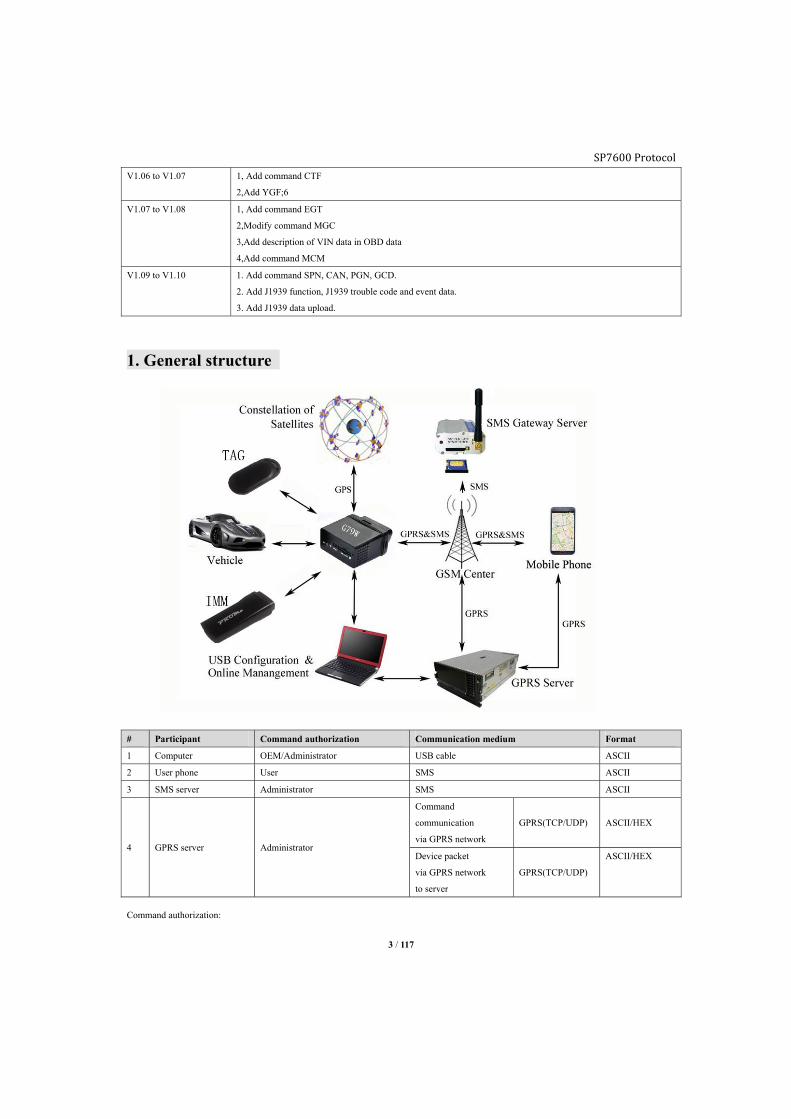
1. General structure
# Participant Command authorization Communication medium Format
1 Computer OEM/Administrator USB cable ASCII
2 User phone User SMS ASCII
3 SMS server Administrator SMS ASCII
4 GPRS server Administrator
Command
communication
via GPRS network
GPRS(TCP/UDP) ASCII/HEX
Device packet
via GPRS network
to server
GPRS(TCP/UDP)
ASCII/HEX
Command authorization:
SP7600 Protocol
4 / 117
■3 levels of authorization are available for different command list in APPENDIX chapter.
OEM: For agent/distributor, all commands are valid for this authorization.
Admin: For administrator, by default admin command list and public command list are valid for this authorization.
OEM authorization is able to use command ACM to customize command list for admin authorization.
User: For user command list only and only via SMS, by default user command list is valid for this authorization. OEM/Admin authorization is
able to use command UCM to customize command list for user.
■Authorization level: OEM > Admin > User
2. Connect with computer
■To use commands in this document to configure and interactive with device:
>Connect device with computer via USB cable and run serial communication software.
>Input ^O (Ctrl + O) 3 times in a row, you will find “Please Input Password:[CR][LF]” on software window.
>Input OEM configuration password “0123456789” (default) and press enter, if the Password is correct, you will find “[LF] Cable Port In OEM
Mode [CR][LF]” on software window.
>Use commands in this document to configure the device.
3. General definition of command3.1. General symbol * Command head
, Command separator
: Only in device reply message, between command word and parameter
; Parameter separator, or separator between command word and parameter
# Command tail
e.g.:
■Command without parameter (Query command)
Send:
Command word1,Command word2
Reply:
Command word1:Parameter1; Parameter2; Parameter3,Command word2: Parameter1; Parameter2; Parameter3
■Command with parameter (Configuration command)
Send:
Command word1;Parameter1;Parameter2;Parameter3,Command word2: Parameter1; Parameter2; Parameter3
Reply:
Command word1:Parameter1; Parameter2; Parameter3,Command word2: Parameter1; Parameter2; Parameter3
■SMS server (Admin) and GPRS server command format
Send:
*GS16, Command word1;Parameter1;Parameter2;Parameter3,Command word2: Parameter1; Parameter2; Parameter3#

SP7600 Protocol
5 / 117
Reply:
*GS16,Device ID, Command word1:Parameter1; Parameter2; Parameter3,Command word2: Parameter1; Parameter2; Parameter3#
3.2. Data conversion
■Under 2 circumstances that the data needs to be converted:
>HEX format with "F8" “1B” in data field.
>ASCII format with “* , ; ( #” in data field.
3.2.1. HEX Format
■If there is "1B" or "F8" in the data field of packet, device will convert them before sending to server.
Conversion method:
Data XOR “1B”, to get data "XX", then add "IB" in the front of "XX", to become 1BXX
e.g.: "F8"XOR “1B” is ” E3" , "F8" will convert to "IBE3".
Note: Server must reserves the above process when it receives data from device to have the genuine data.
3.2.2. ASCII Format
■If there is symbol “* , ; ( #” in the data field of packet, device will convert them before sending to server.
Conversion method:
Add "(" in front of those symbols.
Before * , ; ( #
After (* (, (; (( (#
Note: Server must reserves the above process when it receives data from device to have the genuine data.
3.3. Data verify >Verification adopts “CRC16 – CCITT standard”.
>Device verifies the data before data conversion.
>Generate polynomial method: X16 + X12 + X5+1.
>Base type: 1021.
>Standard reference: ISO in HDLC, ITU x.25, v. 34 / v. 41 / v. 42, the PPP – FCS.
3.4. Packet processing >Device generates raw data.
>CRC verifies raw data.
>Data conversion.
>Packing data by adding packet head and packet tail.
4. Standard packet>SMS server packet length is 230bytes maximum.
>GPRS server packet length is 384bytes maximum.
>If device switches to international roaming status, it will send one standard packet to the server.
>If device switches from GPS unfixed to GPS fixed status, it will send one standard packet to the server.
SP7600 Protocol
6 / 117
■Under certain circumstances, device will send packet to GPRS server and SMS server proactively:
>According to its configuration (e.g.: fixed time report, cornering, fixed distance report).
>Event is being triggered.
>Device forwards SMS from another phone number to user/server.
4.1. Standard packet format
■4 kinds of packet format in total for SP7600
>Connection packet/Heartbeat packet.
>Device information packet, ASCII format.
>Device information packet, HEX format.
>Device forwards packet from other number, HEX format.
Explanation:
# Proactive
report mode Packet data format Report condition
1 Device to
SMS server
Device information packet, ASCII format
(Refer chapter4.3)
According to report configuration
and event status
SMS from other numbers to forward Device will forward packet directly to user/server without
any modification.
2 Device to
GPRS server
Connection packet
Heartbeat packet that report periodically or the first packet
from device when connection with server is being
established successfully.
Device information packet,
ASCII format (Refer chapter4.3)
According to the report configuration and data format set as
ASCII.
Device information packet,
HEX format (Refer chapter4.4)
According to the report configuration and data format set as
HEX.
Device forwarding packet Device will forward SMS packet to user/server according to
configuration.
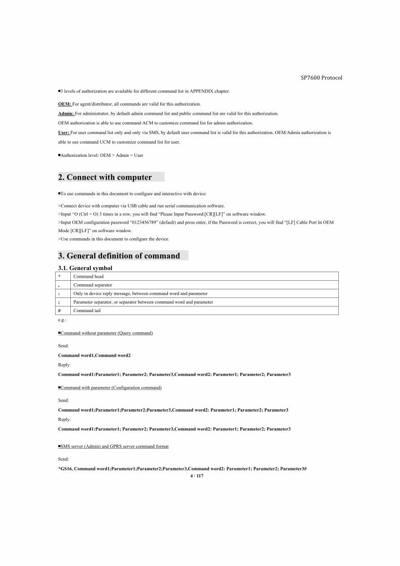
4.2. Heartbeat packet
■Heartbeat packet will be sent under below circumstances:
>The first packet from device when connection with server is being established successfully (including redial).
>Normally it will report periodically to server, to keep the connection with server alive.
>Packet will be coded as ASCII format, it is carrying protocol version and device ID, for the server to recognize different.
Sample, ASCII
*GS 16 , 357852034572894 #
Packet head Protocol version Separator Device ID, 15 digits Packet tail
SP7600 Protocol
7 / 117
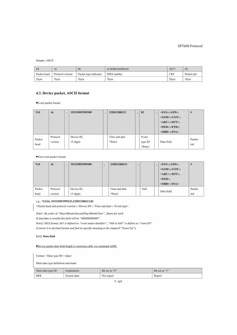
Sample, ASCII
F8 16 00 013FB822050D1D 2D77 F8
Packet head Protocol version Packet type indicator IMEI number CRC Packet tail
1byte 1byte 1byte 7byte 2byte 1byte
4.3. Device packet, ASCII format
■Event packet format
■Non-event packet format
e.g.: *GS16, 351535053999223,235833280213,82
>Packet head and protocol version>,<Device ID>,<Time and date>,<Event type>
Note1: By order of “Hour/Minute/Second/Day/Month/Year”, 2bytes for each
If time/date is invalid this field will be “000000000000”.
Note2: HEX format, bit7 is defined as “event status identifier”, “bit6 to bit0” is defines as “event ID”
(Convert it to decimal format and find its specific meaning in the chapter9 “Event list”).
4.3.1. Data field
■Device packet data field length is customize-able via command ADM.
Format: <Data type ID>:<data>
Main data type definition and mask:
Main data type ID Explanation Bit set as “0” Bit set as “1”
SYS System data Not report Report
*GS 16 , 351535053999389 , 235833280213 , 82 , <SYS>,<GPS>,
<GSM>,<COT>,
<ADC>,<DTT>,
<IWD>,<ETD>,
<OBD>,<FUL>
#
Packet
head
Protocol
version
Device ID,
15 digits
Time and date
*Note1
Event
type ID
*Note2
Data field Packet
tail
*GS 16 , 351535053999389 , 235833280213 , , <SYS>,<GPS>,
<GSM>,<COT>,
<ADC>,<DTT>,
<IWD>,
<OBD>,<FUL>
#
Packet
head
Protocol
version
Device ID,
15 digits
Time and date
*Note1
Null Data field
Packet
tail
SP7600 Protocol
8 / 117
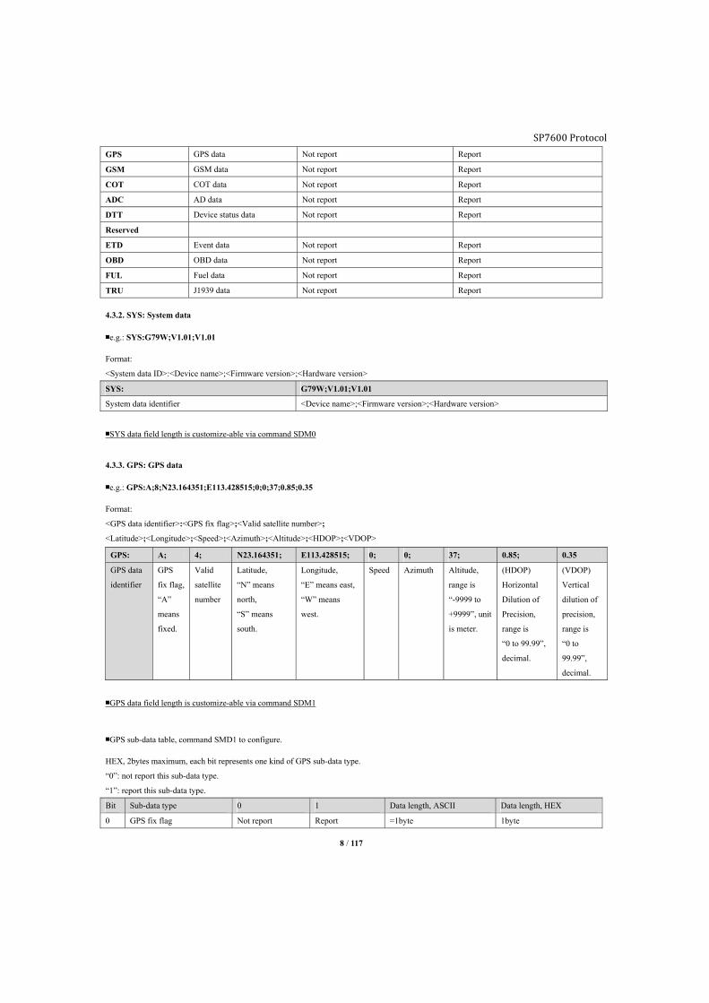
GPS GPS data Not report Report
GSM GSM data Not report Report
COT COT data Not report Report
ADC AD data Not report Report
DTT Device status data Not report Report
Reserved
ETD Event data Not report Report
OBD OBD data Not report Report
FUL Fuel data Not report Report
TRU J1939 data Not report Report
4.3.2. SYS: System data
■e.g.: SYS:G79W;V1.01;V1.01
Format:
<System data ID>:<Device name>;<Firmware version>;<Hardware version>
SYS: G79W;V1.01;V1.01
System data identifier <Device name>;<Firmware version>;<Hardware version>
■SYS data field length is customize-able via command SDM0
4.3.3. GPS: GPS data
■e.g.: GPS:A;8;N23.164351;E113.428515;0;0;37;0.85;0.35
Format:
<GPS data identifier>:<GPS fix flag>;<Valid satellite number>;
<Latitude>;<Longitude>;<Speed>;<Azimuth>;<Altitude>;<HDOP>;<VDOP>
■GPS data field length is customize-able via command SDM1
■GPS sub-data table, command SMD1 to configure.
HEX, 2bytes maximum, each bit represents one kind of GPS sub-data type.
“0”: not report this sub-data type.
“1”: report this sub-data type.
Bit Sub-data type 0 1 Data length, ASCII Data length, HEX
0 GPS fix flag Not report Report =1byte 1byte
GPS: A; 4; N23.164351; E113.428515; 0; 0; 37; 0.85; 0.35
GPS data
identifier
GPS
fix flag,
“A”
means
fixed.
Valid
satellite
number
Latitude,
“N” means
north,
“S” means
south.
Longitude,
“E” means east,
“W” means
west.
Speed Azimuth Altitude,
range is
“-9999 to
+9999”, unit
is meter.
(HDOP)
Horizontal
Dilution of
Precision,
range is
“0 to 99.99”,
decimal.
(VDOP)
Vertical
dilution of
precision,
range is
“0 to
99.99”,
decimal.
SP7600 Protocol
9 / 117
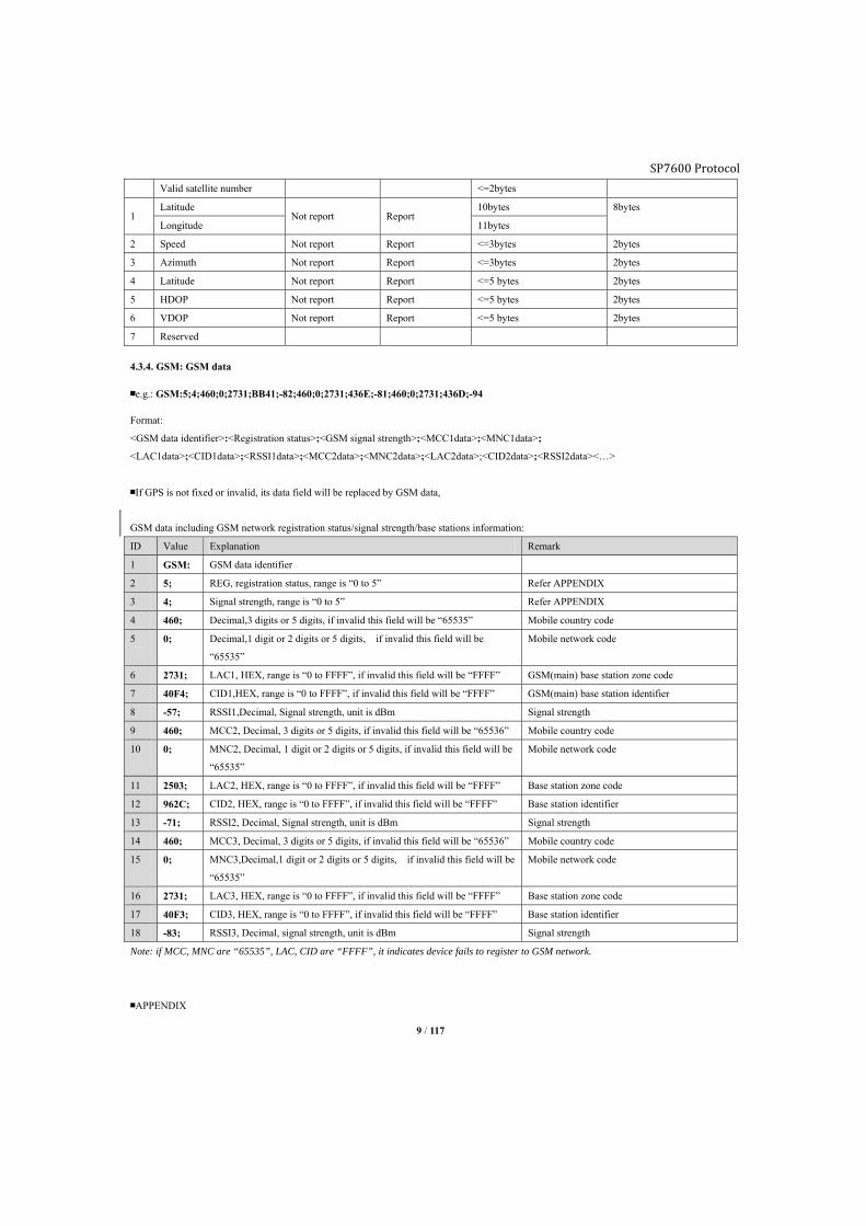
Valid satellite number <=2bytes
1 Latitude
Not report Report 10bytes 8bytes
Longitude 11bytes
2 Speed Not report Report <=3bytes 2bytes
3 Azimuth Not report Report <=3bytes 2bytes
4 Latitude Not report Report <=5 bytes 2bytes
5 HDOP Not report Report <=5 bytes 2bytes
6 VDOP Not report Report <=5 bytes 2bytes
7 Reserved
4.3.4. GSM: GSM data
■e.g.: GSM:5;4;460;0;2731;BB41;-82;460;0;2731;436E;-81;460;0;2731;436D;-94
Format:
<GSM data identifier>:<Registration status>;<GSM signal strength>;<MCC1data>;<MNC1data>;
<LAC1data>;<CID1data>;<RSSI1data>;<MCC2data>;<MNC2data>;<LAC2data>;<CID2data>;<RSSI2data><…>
■If GPS is not fixed or invalid, its data field will be replaced by GSM data,
GSM data including GSM network registration status/signal strength/base stations information:
ID Value Explanation Remark
1 GSM: GSM data identifier
2 5; REG, registration status, range is “0 to 5” Refer APPENDIX
3 4; Signal strength, range is “0 to 5” Refer APPENDIX
4 460; Decimal,3 digits or 5 digits, if invalid this field will be “65535” Mobile country code
5 0; Decimal,1 digit or 2 digits or 5 digits, if invalid this field will be
“65535”
Mobile network code
6 2731; LAC1, HEX, range is “0 to FFFF”, if invalid this field will be “FFFF” GSM(main) base station zone code
7 40F4; CID1,HEX, range is “0 to FFFF”, if invalid this field will be “FFFF” GSM(main) base station identifier
8 -57; RSSI1,Decimal, Signal strength, unit is dBm Signal strength
9 460; MCC2, Decimal, 3 digits or 5 digits, if invalid this field will be “65536” Mobile country code
10 0; MNC2, Decimal, 1 digit or 2 digits or 5 digits, if invalid this field will be
“65535”
Mobile network code
11 2503; LAC2, HEX, range is “0 to FFFF”, if invalid this field will be “FFFF” Base station zone code
12 962C; CID2, HEX, range is “0 to FFFF”, if invalid this field will be “FFFF” Base station identifier
13 -71; RSSI2, Decimal, Signal strength, unit is dBm Signal strength
14 460; MCC3, Decimal, 3 digits or 5 digits, if invalid this field will be “65536” Mobile country code
15 0; MNC3,Decimal,1 digit or 2 digits or 5 digits, if invalid this field will be
“65535”
Mobile network code
16 2731; LAC3, HEX, range is “0 to FFFF”, if invalid this field will be “FFFF” Base station zone code
17 40F3; CID3, HEX, range is “0 to FFFF”, if invalid this field will be “FFFF” Base station identifier
18 -83; RSSI3, Decimal, signal strength, unit is dBm Signal strength
Note: if MCC, MNC are “65535”, LAC, CID are “FFFF”, it indicates device fails to register to GSM network.
■APPENDIX

SP7600 Protocol
10 / 117
REG value
REG Explanation SMS/Voice/GPRS connectivity
0 Fail to register, device is not trying to register to any mobile network ×
1 Register successfully √
2 Fail to register, but device is trying to register to mobile network again ×
3 Register intention is being rejected by mobile network ×
4 Unknown reason ×
5 Register to roaming network successfully √
CSQ value
Signal Level RSSI
0 <= -112dBm
1 <= -97dBm
2 <= -82dBm
3 <= -67dBm
4 <= -52dBm
5 >= -51dBm
■GSM data field length is customize-able via command SDM2
HEX, 2bytes maximum, each bit represents one kind of GSM sub-data type.
“0” do not report this sub-data type.
“1” report this sub-data type.
Bit GSM sub-data type 0 1 Data length, ASCII Data length, HEX
0 Registration status
Not report Report =1byte 1byte
CSQ signal level =1byte
1 First base station Not report Report <=25bytes =8bytes
2 Second base station Not report Report <=25bytes =8bytes
3 Third base station Not report Report <=25bytes =8bytes
4 Fourth base station Not report Report <=25bytes =8bytes
5 Fifth base station Not report Report <=25bytes =8bytes
6 Sixth base station Not report Report <=25bytes =8bytes
7 Seventh base station Not report Report <=25bytes =8bytes
4.3.5. COT: COT data
■e.g.: COT:4294967295;99999:00:00
Format:
<COT data identifier>: <Odometer>;<Engine hour>
COT: 4294967295;99999:00:00
COT data
identifier
<Odometer>:4294967295
Range is “0 to 4294967295”, Unit is “meter”
This value represents accumulated mileage of vehicle. If select J1939 function, the mileage will be the value read from
truck’s odometer. It has nothing to do with command MGS.
<Engine hour>:99999:00:00
SP7600 Protocol
11 / 117
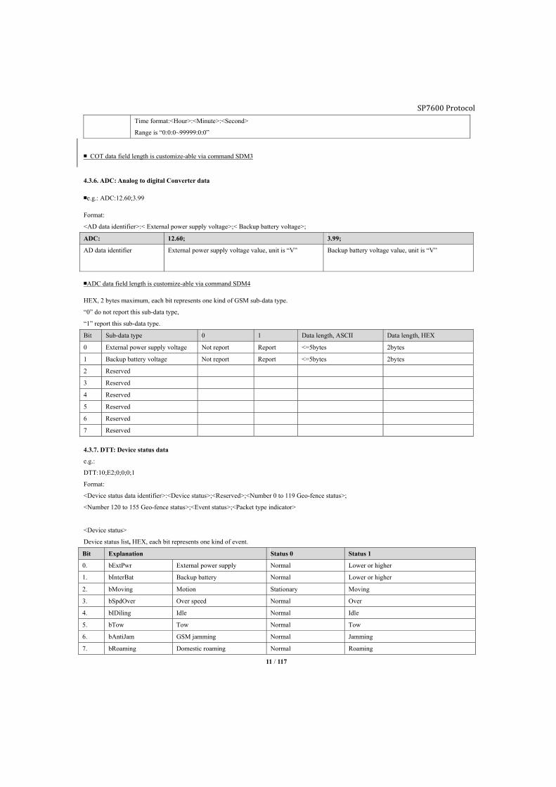
Time format:<Hour>:<Minute>:<Second>
Range is “0:0:0~99999:0:0”
■ COT data field length is customize-able via command SDM3
4.3.6. ADC: Analog to digital Converter data
■e.g.: ADC:12.60;3.99
Format:
<AD data identifier>:< External power supply voltage>;< Backup battery voltage>;
ADC: 12.60; 3.99;
AD data identifier External power supply voltage value, unit is “V” Backup battery voltage value, unit is “V”
■ADC data field length is customize-able via command SDM4
HEX, 2 bytes maximum, each bit represents one kind of GSM sub-data type.
“0” do not report this sub-data type,
“1” report this sub-data type.
Bit Sub-data type 0 1 Data length, ASCII Data length, HEX
0 External power supply voltage Not report Report <=5bytes 2bytes
1 Backup battery voltage Not report Report <=5bytes 2bytes
2 Reserved
3 Reserved
4 Reserved
5 Reserved
6 Reserved
7 Reserved
4.3.7. DTT: Device status data
e.g.:
DTT:10;E2;0;0;0;1
Format:
<Device status data identifier>:<Device status>;<Reserved>;<Number 0 to 119 Geo-fence status>;
<Number 120 to 155 Geo-fence status>;<Event status>;<Packet type indicator>
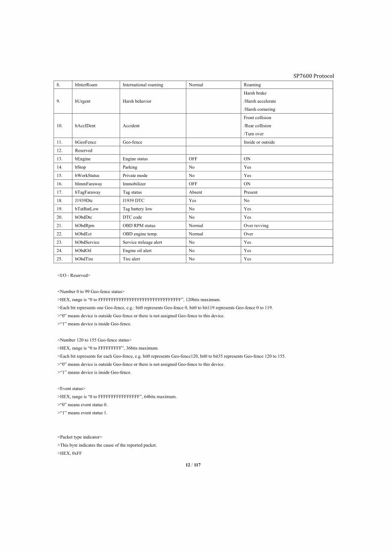
<Device status>
Device status list, HEX, each bit represents one kind of event.
Bit Explanation Status 0 Status 1
0. bExtPwr External power supply Normal Lower or higher
1. bInterBat Backup battery Normal Lower or higher
2. bMoving Motion Stationary Moving
3. bSpdOver Over speed Normal Over
4. bIDiling Idle Normal Idle
5. bTow Tow Normal Tow
6. bAntiJam GSM jamming Normal Jamming
7. bRoaming Domestic roaming Normal Roaming
SP7600 Protocol
12 / 117
8. bInterRoam International roaming Normal Roaming
9. bUrgent Harsh behavior
Harsh brake
/Harsh accelerate
/Harsh cornering
10. bAccIDent Accident
Front collision
/Rear collision
/Turn over
11. bGeoFence Geo-fence Inside or outside
12. Reserved
13. bEngine Engine status OFF ON
14. bStop Parking No Yes
15. bWorkStatus Private mode No Yes
16. bImmFaraway Immobilizer OFF ON
17. bTagFaraway Tag status Absent Present
18. J1939Dtc J1939 DTC Yes No
19. bTatBatLow Tag battery low No Yes
20. bObdDtc DTC code No Yes
21. bObdRpm OBD RPM status Normal Over revving
22. bObdEct OBD engine temp. Normal Over
23. bObdService Service mileage alert No Yes
24. bObdOil Engine oil alert No Yes
25. bObdTire Tire alert No Yes
<I/O - Reserved>
<Number 0 to 99 Geo-fence status>
>HEX, range is “0 to FFFFFFFFFFFFFFFFFFFFFFFFFFFFFFFF”, 120bits maximum.
>Each bit represents one Geo-fence, e.g.: bit0 represents Geo-fence 0, bit0 to bit119 represents Geo-fence 0 to 119.
>“0” means device is outside Geo-fence or there is not assigned Geo-fence to this device.
>“1” means device is inside Geo-fence.
<Number 120 to 155 Geo-fence status>
>HEX, range is “0 to FFFFFFFFF”, 36bits maximum.
>Each bit represents for each Geo-fence, e.g. bit0 represents Geo-fence120, bit0 to bit35 represents Geo-fence 120 to 155.
>“0” means device is outside Geo-fence or there is not assigned Geo-fence to this device.
>“1” means device is inside Geo-fence.
<Event status>
>HEX, range is “0 to FFFFFFFFFFFFFFFF”, 64bits maximum.
>“0” means event status 0.
>“1” means event status 1.
<Packet type indicator>
>This byte indicates the cause of the reported packet.
>HEX, 0xFF
SP7600 Protocol
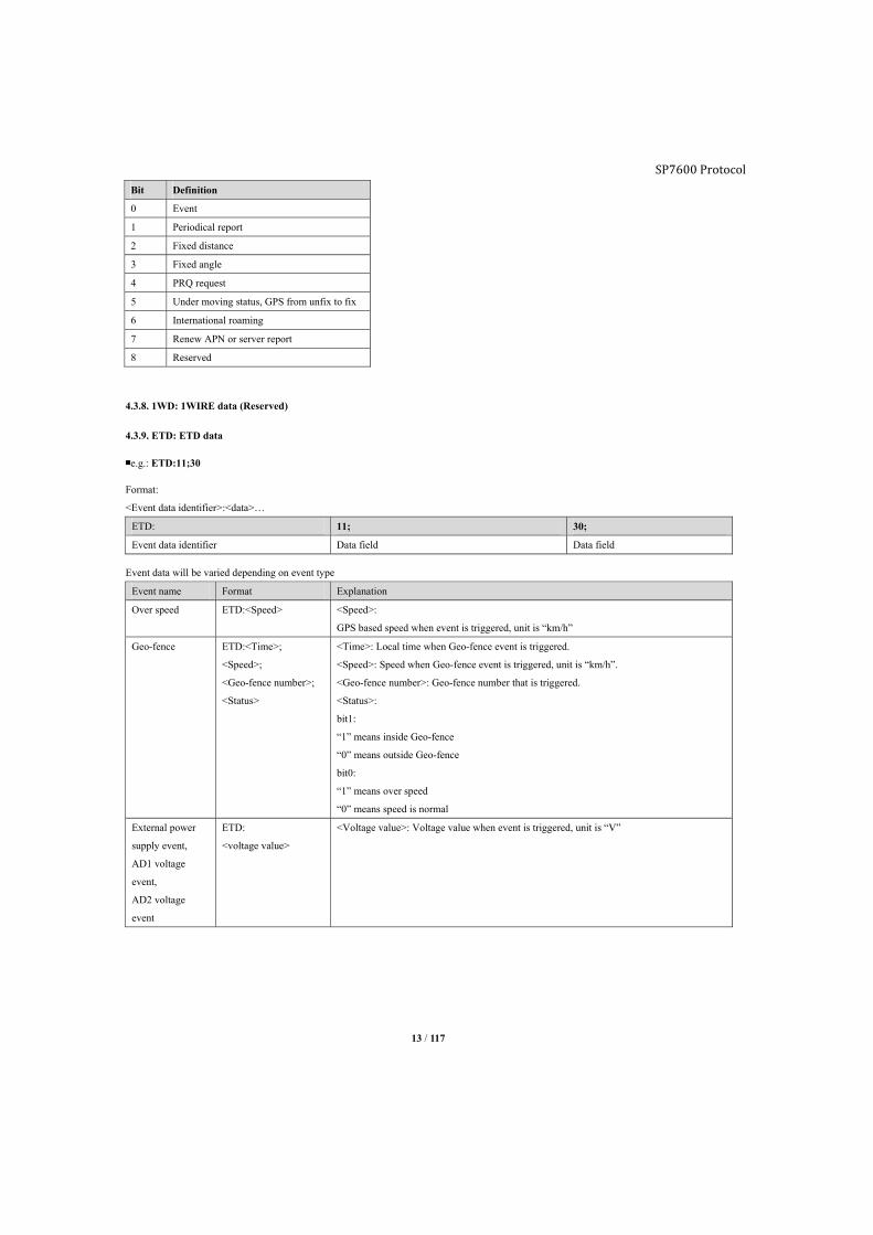
13 / 117
Bit Definition
0 Event
1 Periodical report
2 Fixed distance
3 Fixed angle
4 PRQ request
5 Under moving status, GPS from unfix to fix
6 International roaming
7 Renew APN or server report
8 Reserved
4.3.8. 1WD: 1WIRE data (Reserved)
4.3.9. ETD: ETD data
■e.g.: ETD:11;30
Format:
<Event data identifier>:<data>…
ETD: 11; 30;
Event data identifier Data field Data field
Event data will be varied depending on event type
Event name Format Explanation
Over speed ETD:<Speed> <Speed>:
GPS based speed when event is triggered, unit is “km/h”
Geo-fence ETD:<Time>;
<Speed>;
<Geo-fence number>;
<Status>
<Time>: Local time when Geo-fence event is triggered.
<Speed>: Speed when Geo-fence event is triggered, unit is “km/h”.
<Geo-fence number>: Geo-fence number that is triggered.
<Status>:
bit1:
“1” means inside Geo-fence
“0” means outside Geo-fence
bit0:
“1” means over speed
“0” means speed is normal
External power
supply event,
AD1 voltage
event,
AD2 voltage
event
ETD:
<voltage value>
<Voltage value>: Voltage value when event is triggered, unit is “V”
SP7600 Protocol
14 / 117
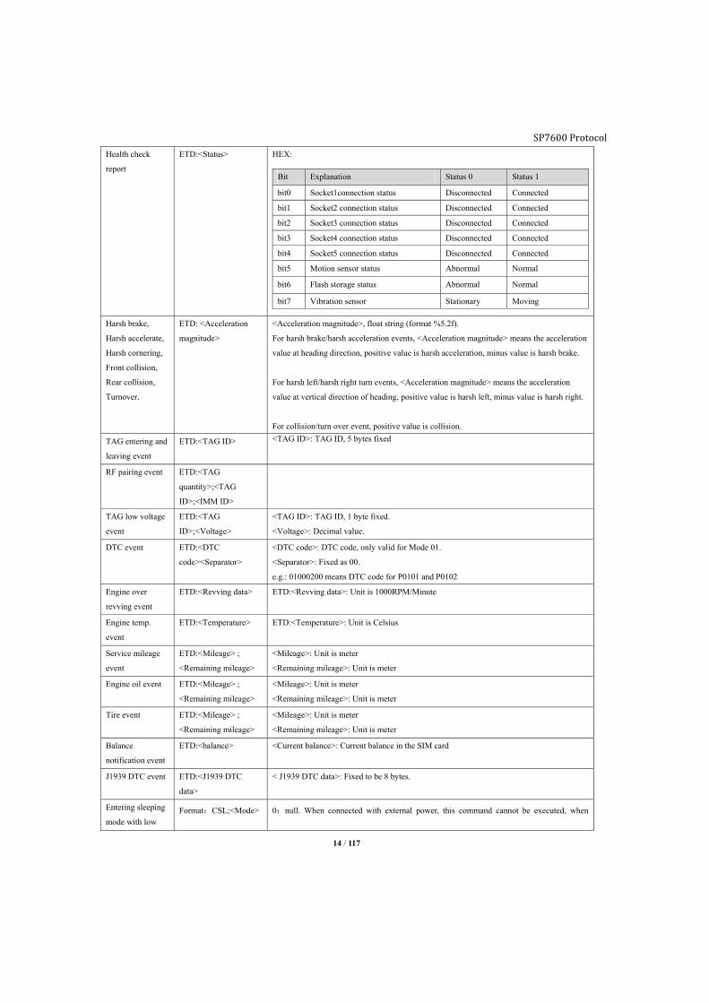
Health check
report
ETD:<Status> HEX:
Bit Explanation Status 0 Status 1
bit0 Socket1connection status Disconnected Connected
bit1 Socket2 connection status Disconnected Connected
bit2 Socket3 connection status Disconnected Connected
bit3 Socket4 connection status Disconnected Connected
bit4 Socket5 connection status Disconnected Connected
bit5 Motion sensor status Abnormal Normal
bit6 Flash storage status Abnormal Normal
bit7 Vibration sensor Stationary Moving
Harsh brake,
Harsh accelerate,
Harsh cornering,
Front collision,
Rear collision,
Turnover.
ETD: <Acceleration
magnitude>
<Acceleration magnitude>, float string (format %5.2f).
For harsh brake/harsh acceleration events, <Acceleration magnitude> means the acceleration
value at heading direction, positive value is harsh acceleration, minus value is harsh brake.
For harsh left/harsh right turn events, <Acceleration magnitude> means the acceleration
value at vertical direction of heading, positive value is harsh left, minus value is harsh right.
For collision/turn over event, positive value is collision.
TAG entering and
leaving event
ETD:<TAG ID> <TAG ID>: TAG ID, 5 bytes fixed
RF pairing event ETD:<TAG
quantity>;<TAG
ID>;<IMM ID>
TAG low voltage
event
ETD:<TAG
ID>;<Voltage>
<TAG ID>: TAG ID, 1 byte fixed.
<Voltage>: Decimal value.
DTC event ETD:<DTC
code><Separator>
<DTC code>: DTC code, only valid for Mode 01.
<Separator>: Fixed as 00.
e.g.: 01000200 means DTC code for P0101 and P0102
Engine over
revving event
ETD:<Revving data> ETD:<Revving data>: Unit is 1000RPM/Minute
Engine temp.
event
ETD:<Temperature> ETD:<Temperature>: Unit is Celsius
Service mileage
event
ETD:<Mileage> ;
<Remaining mileage>
<Mileage>: Unit is meter
<Remaining mileage>: Unit is meter
Engine oil event ETD:<Mileage> ;
<Remaining mileage>
<Mileage>: Unit is meter
<Remaining mileage>: Unit is meter
Tire event ETD:<Mileage> ;
<Remaining mileage>
<Mileage>: Unit is meter
<Remaining mileage>: Unit is meter
Balance
notification event
ETD:<balance> <Current balance>: Current balance in the SIM card
J1939 DTC event ETD:<J1939 DTC
data>
< J1939 DTC data>: Fixed to be 8 bytes.
Entering sleeping
mode with low Format:CSL;<Mode> 0:null. When connected with external power, this command cannot be executed, when

SP7600 Protocol
15 / 117
voltage battery disconnected with external power, GPRS cannot send this command.
1:Enable the device entering sleeping mode;aa
■Event data field length is customize-able via command SDM7
4.3.10. OBD: OBDII data
■HEX format
Data varies depending on setting of command OBP, PID is in order of unit reading, each PID data length varies.
e.g.: 0341077E04410C000003410D000743010002000300
Format: <ODB data identifier>;<Data>
OBD: OBD data identifier
03 OBDII data length#1
41 01 mode return flag
07 PID of 01 mode
7E PID07 data, 01 mode
04 OBDII data length#2
41 01 return flag
0C PID of 01 mode
0000 PID0C data, 01 mode
03 OBDII data length#3
41 01 mode return flag
0D PID of 01 mode
00 PID0D data, 01 mode
07 DTC code length
43 DTC code flagaa
0100 DTC#1 data,P0100
0200 DTC#2 data,P0200
0300 DTC#3 data,P0300
Notes:
There are two different kinds of VIN data formats according to different OBD protocols.
1. VIN data format defined by ISO 9141-2, ISO 14230-4 and SAE J1850 is as below:
Send command:
OBC;0902
Device will reply:
OBC:0902
4902013147314A
49020243353434
49020334523732
49020435323336
49020539000000
16 / 117
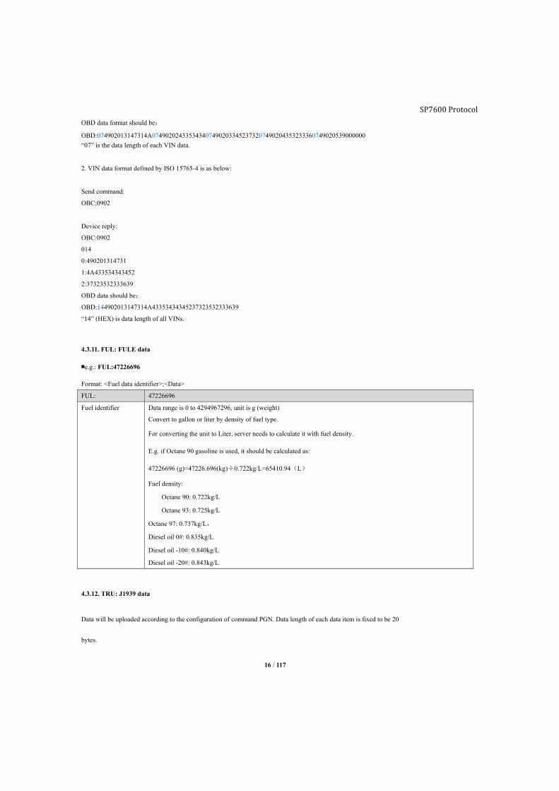
OBD data format should be:
OBD:074902013147314A0749020243353434074902033452373207490204353233360749020539000000 “07” is the data length of each VIN data.
2. VIN data format defined by ISO 15765-4 is as below:
Send command:
OBC;0902
Device reply:
OBC:0902
014
0:490201314731
1:4A433534343452
2:37323532333639
OBD data should be:
OBD:144902013147314A43353434345237323532333639
“14” (HEX) is data length of all VINs.
4.3.11. FUL: FULE data
■e.g.: FUL:47226696
Format: <Fuel data identifier>;<Data>
FUL: 47226696
Fuel identifier Data range is 0 to 4294967296, unit is g (weight)
Convert to gallon or liter by density of fuel type.
For converting the unit to Liter, server needs to calculate it with fuel density.
E.g. if Octane 90 gasoline is used, it should be calculated as:
47226696 (g)=47226.696(kg)÷0.722kg/L=65410.94(L)
Fuel density:
Octane 90: 0.722kg/L
Octane 93: 0.725kg/L
Octane 97: 0.737kg/L,
Diesel oil 0#: 0.835kg/L
Diesel oil -10#: 0.840kg/L
Diesel oil -20#: 0.843kg/L
4.3.12. TRU: J1939 data
Data will be uploaded according to the configuration of command PGN. Data length of each data item is fixed to be 20
bytes.
SP7600 Protocol
17 / 117
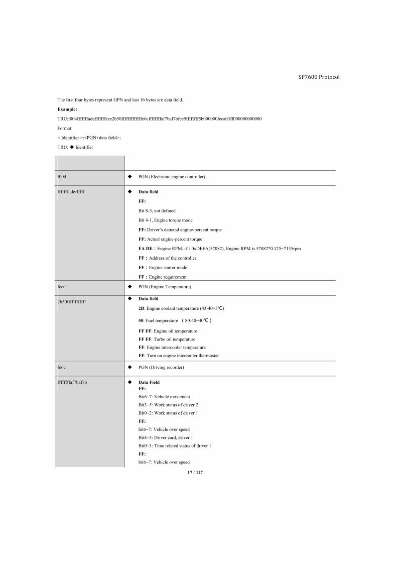
The first four bytes represent GPN and last 16 bytes are data field.
Example:
TRU:f004fffffffadefffffffeee2b50fffffffffffffe6cffffffffaf7baf7bfee9ffffffff5b000000feca03ff000000000000
Format:
< Identifier >:<PGN+data field>;
TRU: Identifier
f004 PGN (Electronic engine controller)
fffffffadeffffff Data field
FF:
Bit 8-5, not defined
Bit 4-1, Engine torque mode
FF: Driver’s demand engine-percent torque
FF: Actual engine-percent torque
FA DE:Engine RPM, it’s 0xDEFA(57082), Engine RPM is 57082*0.125=7135rpm
FF:Address of the controller
FF:Engine starter mode
FF:Engine requirement
feee PGN (Engine Temperature)
2b50ffffffffffff Data field
2B: Engine coolant temperature (43-40=3℃)
50: Fuel temperature (80-40=40℃)
FF FF: Engine oil temperature
FF FF: Turbo oil temperature
FF: Engine intercooler temperature
FF: Turn on engine intercooler thermostat
fe6c PGN (Driving recorder)
ffffffffaf7baf7b Data Field FF:
Bit6~7: Vehicle movement
Bit3~5: Work status of driver 2
Bit0~2: Work status of driver 1
FF:
bit6~7: Vehicle over speed
Bit4~5: Driver card, driver 1
Bit0~3: Time related status of driver 1
FF:
bit6~7: Vehicle over speed
SP7600 Protocol
SP7600 Protocol
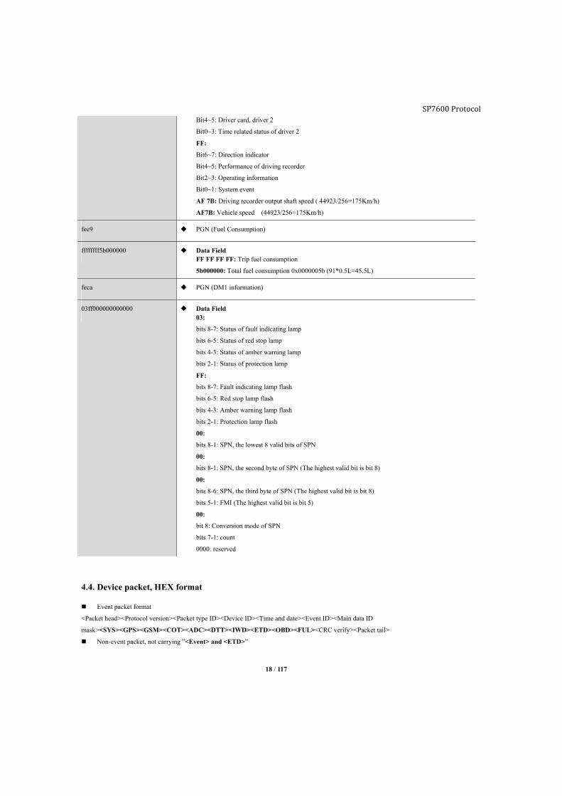
18 / 117
Bit4~5: Driver card, driver 2
Bit0~3: Time related status of driver 2
FF:
Bit6~7: Direction indicator
Bit4~5: Performance of driving recorder
Bit2~3: Operating information
Bit0~1: System event
AF 7B: Driving recorder output shaft speed ( 44923/256=175Km/h)
AF7B: Vehicle speed (44923/256=175Km/h)
fee9 PGN (Fuel Consumption)
ffffffff5b000000 Data Field FF FF FF FF: Trip fuel consumption
5b000000: Total fuel consumption 0x0000005b (91*0.5L=45.5L)
feca PGN (DM1 information)
03ff000000000000 Data Field 03:
bits 8-7: Status of fault indicating lamp
bits 6-5: Status of red stop lamp
bits 4-3: Status of amber warning lamp
bits 2-1: Status of protection lamp
FF:
bits 8-7: Fault indicating lamp flash
bits 6-5: Red stop lamp flash
bits 4-3: Amber warning lamp flash
bits 2-1: Protection lamp flash
00:
bits 8-1: SPN, the lowest 8 valid bits of SPN
00:
bits 8-1: SPN, the second byte of SPN (The highest valid bit is bit 8)
00:
bits 8-6: SPN, the third byte of SPN (The highest valid bit is bit 8)
bits 5-1: FMI (The highest valid bit is bit 5)
00:
bit 8: Conversion mode of SPN
bits 7-1: count
0000: reserved
4.4. Device packet, HEX format
Event packet format
<Packet head><Protocol version><Packet type ID><Device ID><Time and date><Event ID><Main data ID
mask><SYS><GPS><GSM><COT><ADC><DTT><IWD><ETD><OBD><FUL><CRC verify><Packet tail>
Non-event packet, not carrying ”<Event> and <ETD>”

19 / 117
<Packet head><Protocol version><Packet type ID><Device ID><Time and date><Main data ID
mask><SYS><GPS><GSM><COT><ADC><DTT><IWD><OBD><FUL><CRC verify><Packet tail>
Packet format:
Packet
head
Protocol
version
Packet
type ID
HEX,
Device ID
Time and
date
Event
ID
Main data
mask
Data field CRC
verify
Packet
tail
F8 16 41 013FB822
050D1D
153AA8A6 82 00FF <SYS><GPS><GSM>
<COT><ADC><DTT>
<ETD><OBD><FUL>
2D77 F8
1byte 1byte 1byte 7bytes 4bytes 1byte 2bytes Vary 2bytes 1byte
<Packet type ID>
HEX, packet type identifier
Bit7:
“0” means long ID format, G79W only supports this format.
“1” means short ID format.
Bit6:
“0" means non-event packet
“1” means event packet, carrying <ETD>.
“Bit0-Bit5”:
“1” means device packet.
“2” means forwarding packet.
<Device ID>
HEX, 7bytes fixed, device IMEI.
<Time and date>
4bytes unsigned integer data, high byte ahead, start from year 2000, Jan 1st 00(HH)-00(MM)-00(SS).
e.g.: HEX data “195A7F9E” converts to decimal is 425361310 seconds, which means 2013-06-64 03:55:10
<Event ID>
HEX, 1byte fixed.
Bit7 represents “Device status flag”.
“Bit6 to Bit0” represents “Event ID”, need to convert from HEX to decimal and find its definition in chapter9 “Event list”. e.g.: “0x82”
represents event “Quit parking”.
Note: Non-event packet does not carry this field.
<Main data mask>
HEX, 2bytes fixed.
Each bit represents each type of data, “1” means reporting this type sub-data, “0” means not reporting this type sub-data.
e.g.: “0x3B” converts to binary is “0011 1011”, which means only report <SYS><GPS><COT><ADC><DTT>
4.4.1. Data field
SP7600 Protocol

SP7600 Protocol
20 / 117
■Data field data length is customize-able via command ADM.
Format: “<Data length><data1><data2><Data length>data1><data2>…”
Main data mask, HEX, 2bytes
Main data ID bit Main data type Explanation
Bit definition
0 1
0 SYS System data Not report Report
1 GPS GPS data Not report Report
2 GSM GSM data Not report Report
3 COT COT data Not report Report
4 ADC Analog to digital converter data Not report Report
5 DTT Device status data Not report Report
6 Reserved
7 ETD Event data Not report Report
8 OBD OBDII data Not report Report
9 FUL Fuel consumption Not report Report
10 TRU J1939 data Not report Report
11 Reserved Reserved
12 Reserved Reserved
13 Reserved Reserved
14 Reserved Reserved
15 Reserved Reserved
4.4.2. SYS: System data
Format:
12 0447373957 1556312E3030265668312E3032
(In ASCII: G79W V1.00 Vh1.02)
<System data length><Sub-data ID and data length ><Sub-data field>…
12 03 47373957 1556312E3030
SYS data length 0 3 473653 1 5 56312E3030
Sub-data ID Sub-data Length Sub-data field Sub-data ID Sub-data Length Sub-data field
1byte 1byte Not fixed 1byte Not fixed
<Sub-data ID and length>
1byte fixed, High 4bits represents sub-data type ID, and low 4bits represents sub-data length
“System data” sub-data type list
Sub-data ID Sub-data type Data length, ASCII Data length, HEX
0 Device name <=15Bytes <=15Bytes
1 Firmware version <=8Bytes <=8Bytes
2 Hardware version <=8Bytes <=8Bytes
4.4.3. GPS: GPS data
Format:
21 / 117
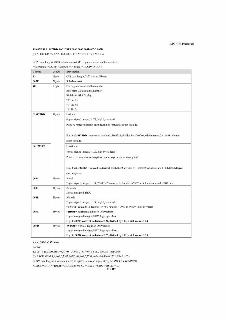
15 007F 48 016175DD 06C2C8E8 0000 0000 004B 007C 007D
(In ASCII: GPS:A;8;N23.164381;E113.428712;0;0;75;1.24;1.25)
<GPS data length><GPS sub-data mask><Fix sign and valid satellite number>
<Coordinate><Speed><Azimuth><Altitude><HDOP><VDOP>
Content Length Explanation
15 1byte GPS data length, ”15” means 21bytes
007F 2bytes Sub-data mask
48 1 byte Fix flag and valid satellite number.
Bit0-bit4: Valid satellite number
Bit5-Bit6: GPS fix flag,
“0” not fix
“1” 2D fix
“2” 3D fix
016175DD 8bytes Latitude
4bytes signed integer, HEX, high byte ahead.
Positive represents north-latitude, minus represents south-latitude.
E.g.: 0x016175DD,convert to decimal 23164381, divided by 1000000, which means 23.164381 degree
north-latitude.
06C2C8E8 Longitude
4bytes signed integer, HEX, high byte ahead.
Positive represents east-longitude, minus represents west-longitude
E.g.: 0x06C2C8E8,convert to decimal 113428712, divided by 1000000, which means 113.428712 degree
east-longitude
003C 2bytes Speed
2bytes signed integer, HEX, “0x003C” converts to decimal is “60”, which means speed is 60 km/h.
0000 2bytes Azimuth
2bytes unsigned, HEX
004B 2bytes Altitude
2bytes signed integer, HEX, high byte ahead.
“0x004B” converts to decimal is “75”, range is “-9999 to +9999”, unit is “meter”
007C 2bytes <HDOP> Horizontal Dilution Of Precision
2bytes unsigned integer, HEX, high byte ahead.
E.g.: 0x007C, convert to decimal 124, divided by 100, which means 1.24
007D 2bytes <VDOP> Vertical Dilution Of Precision
2bytes unsigned integer, HEX, high byte ahead.
E.g.: 0x007D, convert to decimal 125, divided by 100, which means 1.25
4.4.4. GSM: GSM data
Format:
1A 0F 14 1CC000 2503 962C 40 1CC000 2731 40F4 56 1CC000 2731 BB42 66
(In ASCII: GSM:1;4;460;0;2503;962C;-64;460;0;2731;40F4;-86;460;0;2731;BB42;-102)
<GSM data length><Sub-data mask><Register status and signal strength><MCC1 and MNC1>
<LAC1><CID1><RSSI1><MCC2 and MNC2><LAC2><CID2><RSSI2><…>
SP7600 Protocol

SP7600 Protocol
22 / 117
<MCC1 and MNC1 >: Fixed 3bytes, “Bit0-Bit11” represents MNC1, “Bit12-Bit23” represents MCC1.
Content Length Explanation
1A 1byte GSM data field length, ”0A” is 10bytes
0F 1byte Sub-data mask
14 1byte Register status and signal strength, high 4bits represents network register status, low 4bits represents signal
strength.
1CC000 3byte <MCC1 “mobile country code” and MNC1 “mobile network code”>
2503 2byte <LAC1> : GSM main base station zone code
HEX, converts to decimal is “9475”
962C 2byte < CID1>: GSM main base station ID
HEX, converts to decimal is “38444”
40 1byte <RSSI1>: GSM signal strength
HEX, converts to decimal is “64”, which means strength is “-64dBm”.
1CC000 3byte <MCC2: GSM mobile country code” and MNC2: mobile network code>
2731 2byte <LAC2>: GSM main base station zone code
HEX, converts to decimal is “10033”
40F4 2byte < CID2>: GSM main base station ID
HEX, converts to decimal is “16628”
56 1byte <RSSI2>: GSM signal strength
HEX, converts to decimal is “86”, which means strength is “-86dBm”.
1CC000 3byte <MCC3: GSM mobile country code” and MNC3: mobile network code>
2731 2byte <LAC3>: GSM main base station zone code
HEX, converts to decimal is “10033”
BB42 2byte < CID3>: GSM main base station ID
HEX, converts to decimal is “47938”
66 1byte <RSSI3>: GSM signal strength
HEX, converts to decimal is “102”, which means strength is “-102dBm”.
4.4.5. COT: COT data
Format:
060203E8 1297C2
(In ASCII format: COT:1000;10:47:30)
<COT data length><Sub-data ID and data length><Sub-data field>…
0B 02 03E8 12 97C2
COT data
length
0 2 03E8 1 2 97C2
Sub-data ID Sub-data
length
Sub-data field Sub-data ID Sub-data
length
Sub-data field
1byte 1byte Unfixed 1byte Unfixed
<COT data field length>:
“0B” means COT data field length is 11bytes (convert to decimal).
<Sub data ID and length>: 1byte
“Bit4-Bit7”: Sub-data type identifier
“Bit0-bit3”: Sub-data type length

23 / 117
“COT data” Sub-data type list
Sub-data type ID Sub-data type Data length, ASCII Data length, HEX
0 Odometer <=10Bytes <=5Bytes
1 Engine hour <=10Bytes <=5Bytes
Odometer:
HEX, convert to decimal, unit is “meter”. e.g.: “0x03E8” convert to decimal is “1000”, which means 1000 meters.
Engine hour:
HEX, convert to decimal, unit is “second”. e.g.: “0x97C2” convert to decimal is “38850”, which means 38850 seconds (10H:47M:30S)
4.4.6. AD: AD data
Format:
0403201208
<AD data length><para_id+para_value>…
04 0320 1208
AD data length 0 324 1 208
Sub-data ID Sub-data field Sub-data ID Sub-data field
1byte 2bytes 2bytes
<para_id + para_val>: HEX, 2bytes
para_id: High 4bits, range is “0 to F”, it decides the meaning of “para_val“.
id=0: External power supply
id=1: Backup battery
para_value:
AD_VAL = DECIMAL (para_val)*(AD_MAX – AD_MIN)/4096 + AD_MIN
DECIMAL(para_val ) means convert “para_val” to decimal.
Range is AD_MIN: -10, AD_MAX: 100, unit is “V”
e.g.: convert “0x320” to decimal 800
Formula: 800*(100-(-10))/4096+(-10)=800*110/4096-10=11.48
“AD data” sub-data mask list
Bit Sub-data type Status 0 Status 1 Data length, ASCII Data length, HEX
0 External power Not report Report <=5Bytes 2
1 Backup battery Not report Report <=5Bytes 2
2 Reserved
3 Reserved
4 Reserved
5 Reserved
6 Reserved
7 Reserved
SP7600 Protocol

24 / 117
4.4.7. DTT: Device status data
Format:
0E 0100 11C3 2100 3100 43020000
(In ASCII: DTT:0;C2;0;0;20000)
<DTT data length><Sub-data ID and length><sub-data field><Sub-data ID and length><sub-data field>…
0C 01 00 11 C3 21 00
DTT data
length
0 1 00 1 1 C3 2 1 00
Sub-data
ID
Sub-data
length
Sub-data
field
Sub-data
ID
Sub-data
length
Sub-data field Sub-data
ID
Sub-data
length
Sub-data field
1byte 1byte Unfixed 1byte Unfixed 1byte Unfixed
<DTT data length>: ”0E” represents data field length is 14bytes.
<Sub-data ID and length>: 1byte fixed,“Bit4-Bit7” represents sub-data ID, “Bit0-bit3” represents data length.
Sub-data ID:
“0”: Device status
“1”: I/O status
“2”: Number 0 to 119 Geo-fence status
“3”: Number 120 to 155 Geo-fence status
“4”: Event status
“5”: Packet type indicator
“DTT data” sub-data mask, 16 IDs maximum
Bit Sub-data type Status 0 Status 1 Data length, ASCII Data length, HEX
0 Device status Not report Report <=8Bytes <=5Bytes
1 Reserved
2 Lower 120 Geo-fences status Not report Report <=30Bytes <=15Bytes
3 Higher 36 Geo-fences status Not report Report <=9Bytes <=5Bytes
4 Event status Not report Report <=16Bytes <=9Bytes
5 Packet type indicator Not report Report <=2Bytes =2Bytes
<Device status>: Refer chapter4.3.7 “Device status list”
<I/O status>: Refer chapter4.3.7 “I/O status list”
<Number “0 to 119” Geo-fence status>
HEX, maximum 120bits, range is “0 to FFFFFFFFFFFFFFFFFFFFFFFFFFFFFF”.
Each bit represents each Geo-fence, “bit0 to bit119” represents “Geo-fence0 to Geo-fence119”
”0”: Outside Geo-fence or there is not Geo-fence assigned to device
”1”: Inside Geo-fence
<Number “120 to 155” Geo-fence status>
HEX, range is “0 to 0FFFFFFFFF”.
Each bit represents each Geo-fence, “bit0 to bit3j5” represents “Geo-fence120 to Geo-fence155”
”0”: Outside Geo-fence or there is not Geo-fence assigned to device
”1”: Inside Geo-fence
<Event status>
SP7600 Protocol
25 / 117
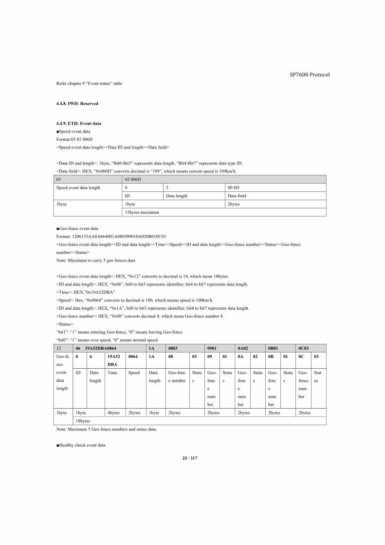
Refer chapter 9 “Event status” table
4.4.8. IWD: Reserved
4.4.9. ETD: Event data
■Speed event data
Format:03 02 006D
<Speed event data length><Data ID and length><Data field>
<Data ID and length>: 1byte, “Bit0-Bit3” represents data length, “Bit4-Bit7” represents data type ID.
<Data field>: HEX, “0x006D” converts decimal is “109”, which means current speed is 109km/h.
03 02 006D
Speed event data length 0 2 00 6D
ID Data length Data field
1byte 1byte 2bytes
15bytes maximum
■Geo-fence event data
Format: 1206153AA8A664001A080309010A020B010C03
<Geo-fence event data length><ID and data length><Time><Speed><ID and data length><Geo-fence number><Status><Geo-fence
number><Status>
Note: Maximum to carry 5 geo fences data
<Geo-fence event data length>: HEX, “0x12” converts to decimal is 18, which mean 18bytes.
<ID and data length>: HEX, “0x06”, bit0 to bit3 represents identifier; bit4 to bit7 represents data length.
<Time>: HEX,”0x19A52DBA”
<Speed>: Hex, “0x0064” converts to decimal is 100, which means speed is 100km/h.
<ID and data length>: HEX, “0x1A”, bit0 to bit3 represents identifier; bit4 to bit7 represents data length.
<Geo-fence number>: HEX, “0x08” converts decimal 8, which mean Geo-fence number 8.
<Status>:
“bit1”: “1” means entering Geo-fence, “0” means leaving Geo-fence.
“bit0”: “1” means over speed, “0” means normal speed.
12 06 19A52DBA0064 1A 0803 0901 0A02 0B01 0C03
Geo-fe
nce
event
data
length
0 6 19A52
DBA
0064 1A 08 03 09 01 0A 02 0B 01 0C 03
ID Data
length
Time Speed Data
length
Geo-fenc
e number
Statu
s
Geo-
fenc
e
num
ber
Statu
s
Geo-
fenc
e
num
ber
Statu
s
Geo-
fenc
e
num
ber
Statu
s
Geo-
fence
num
ber
Stat
us
1byte 1byte 4bytes 2bytes 1byte 2bytes 2bytes 2bytes 2bytes 2bytes
18bytes
Note: Maximum 5 Geo-fence numbers and status data.
■Healthy check event data
SP7600 Protocol

26 / 117
Format: 020144
<Healthy check event data><ID and data length><Data field>
<Data field>: HEX
Bit Name 0 1
bit0 Socket0 Disconnected Connected
bit1 Socket1 Disconnected Connected
bit2 Socket2 Disconnected Connected
bit3 Socket3 Disconnected Connected
bit4 Socket4 Disconnected Connected
bit5 2D accelerate meter Abnormal Normal
bit6 SPI Flash Abnormal Normal
bit7 Vibration sensor Still Vibrate
02 0144
Healthy check event data 0 1 44
ID Data length Data field
1byte fixed 1byte 1byte
2bytes, unfixed
■Harsh/Collision event data
Format: 05 06FF9C00D703E8
07 06FF9C00D703E8
Event data 0 6 FF9C 00D7 03E8
ID Data length X axis data Y axis data Z axis data
1byte fixed 1bytes 2bytes 2bytes 2bytes
5bytes, unfixed
X/Y axis data: HEX, acceleration magnitude equals value/1000, unit is g. Which means:
X: “0XFF9C” equals X:-0.099g
Y: ”0x00D7” equals Y:0.215g
Z: “0x03E8” equals Z:1g
■ADC event
Format: 03 02 02BE
<ADC event data length><ID and data length><Data field>
<ID and data length>: bit0 to bit3 represents data length, bit4 to bit7 represents ID.
<Data field>: HEX, “0x02BE” means 8.85, unit is volt.
03 02 02BE
ADC event data length 0 2 02BE
ID Data length Data field
1byte, fixed 1byte 2bytes
3bytes, unfixed
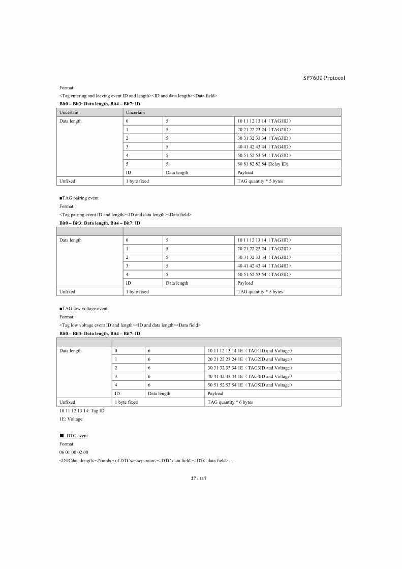
■TAG entering and leaving event
SP7600 Protocol
27 / 117
Format:
<Tag entering and leaving event ID and length><ID and data length><Data field>
Bit0 – Bit3: Data length, Bit4 – Bit7: ID
Uncertain Uncertain
Data length 0 5 10 11 12 13 14(TAG1ID)
1 5 20 21 22 23 24(TAG2ID)
2 5 30 31 32 33 34(TAG3ID)
3 5 40 41 42 43 44(TAG4ID)
4 5 50 51 52 53 54(TAG5ID)
5 5 80 81 82 83 84 (Relay ID)
ID Data length Payload
Unfixed 1 byte fixed TAG quantity * 5 bytes
■TAG pairing event
Format:
<Tag pairing event ID and length><ID and data length><Data field>
Bit0 – Bit3: Data length, Bit4 – Bit7: ID
Data length 0 5 10 11 12 13 14(TAG1ID)
1 5 20 21 22 23 24(TAG2ID)
2 5 30 31 32 33 34(TAG3ID)
3 5 40 41 42 43 44(TAG4ID)
4 5 50 51 52 53 54(TAG5ID)
ID Data length Payload
Unfixed 1 byte fixed TAG quantity * 5 bytes
■TAG low voltage event
Format:
<Tag low voltage event ID and length><ID and data length><Data field>
Bit0 – Bit3: Data length, Bit4 – Bit7: ID
Data length 0 6 10 11 12 13 14 1E(TAG1ID and Voltage)
1 6 20 21 22 23 24 1E(TAG2ID and Voltage)
2 6 30 31 32 33 34 1E(TAG3ID and Voltage)
3 6 40 41 42 43 44 1E(TAG4ID and Voltage)
4 6 50 51 52 53 54 1E(TAG5ID and Voltage)
ID Data length Payload
Unfixed 1 byte fixed TAG quantity * 6 bytes
10 11 12 13 14: Tag ID
1E: Voltage
■ DTC event
Format:
06 01 00 02 00
<DTCdata length><Number of DTCs><separator>< DTC data field>< DTC data field>…
SP7600 Protocol

SP7600 Protocol
28 / 117
06 DTCdata length 1 byte
01 One DTC code 1 byte
00 Separator, fixed to be 00 1 byte
0200 DTC data field 2 bytes
Decode DTC code:
Each trouble code requires 2 bytes to describe. The text description of a trouble code may be decoded as follows. The first character in the
trouble code is determined by the first two bits in the first byte:
Bit7-Bit6 First DTC Character
00 P - Powertrain
01 C - Chassis
10 B - Body
11 U - Network
The second character in the DTC is defined by bit 5 and bit 4 in the first byte:
Bit5-Bit4 Second DTC Character
00 0
01 1
10 2
11 3
The third character in the DTC is defined by bit 3 to bit 0 in the first byte, hex format
Bit 3-Bit0 Third DTC Character
0000 0
0001 1
0010 2
0011 3
0100 4
0101 5
0110 6
0111 7
1000 8
1001 9
1010 A
1011 B
1100 C
1101 D
1110 E
1111 F
The fourth and fifth characters are defined in the same way as the third, but using bit7-bit4 and bit3-bit0 in the second byte.
Example: DTC P0143 should be decoded as below:
SP7600 Protocol
29 / 117
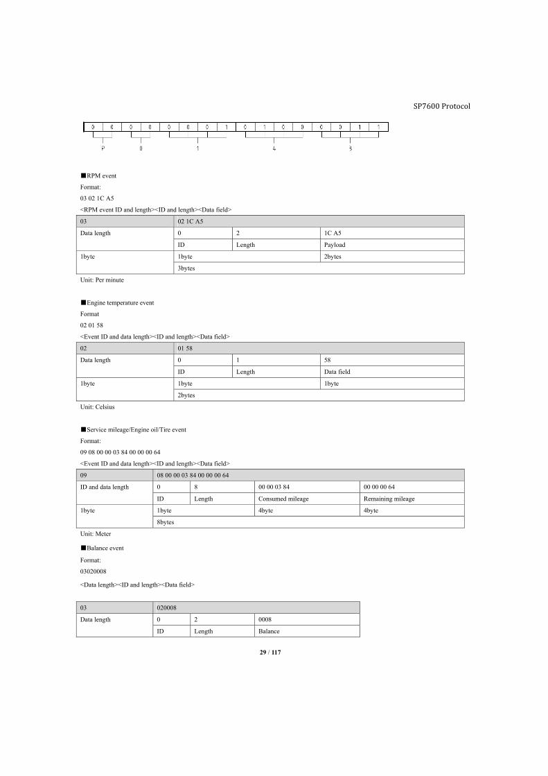
■RPM event
Format:
03 02 1C A5
<RPM event ID and length><ID and length><Data field>
03 02 1C A5
Data length 0 2 1C A5
ID Length Payload
1byte 1byte 2bytes
3bytes
Unit: Per minute
■Engine temperature event
Format
02 01 58
<Event ID and data length><ID and length><Data field>
02 01 58
Data length 0 1 58
ID Length Data field
1byte 1byte 1byte
2bytes
Unit: Celsius
■Service mileage/Engine oil/Tire event
Format:
09 08 00 00 03 84 00 00 00 64
<Event ID and data length><ID and length><Data field>
09 08 00 00 03 84 00 00 00 64
ID and data length 0 8 00 00 03 84 00 00 00 64
ID Length Consumed mileage Remaining mileage
1byte 1byte 4byte 4byte
8bytes
Unit: Meter
■Balance event
Format:
03020008
<Data length><ID and length><Data field>
03 020008
Data length 0 2 0008
ID Length Balance
SP7600 Protocol
30 / 117
1byte 1byte 2byte
3bytes
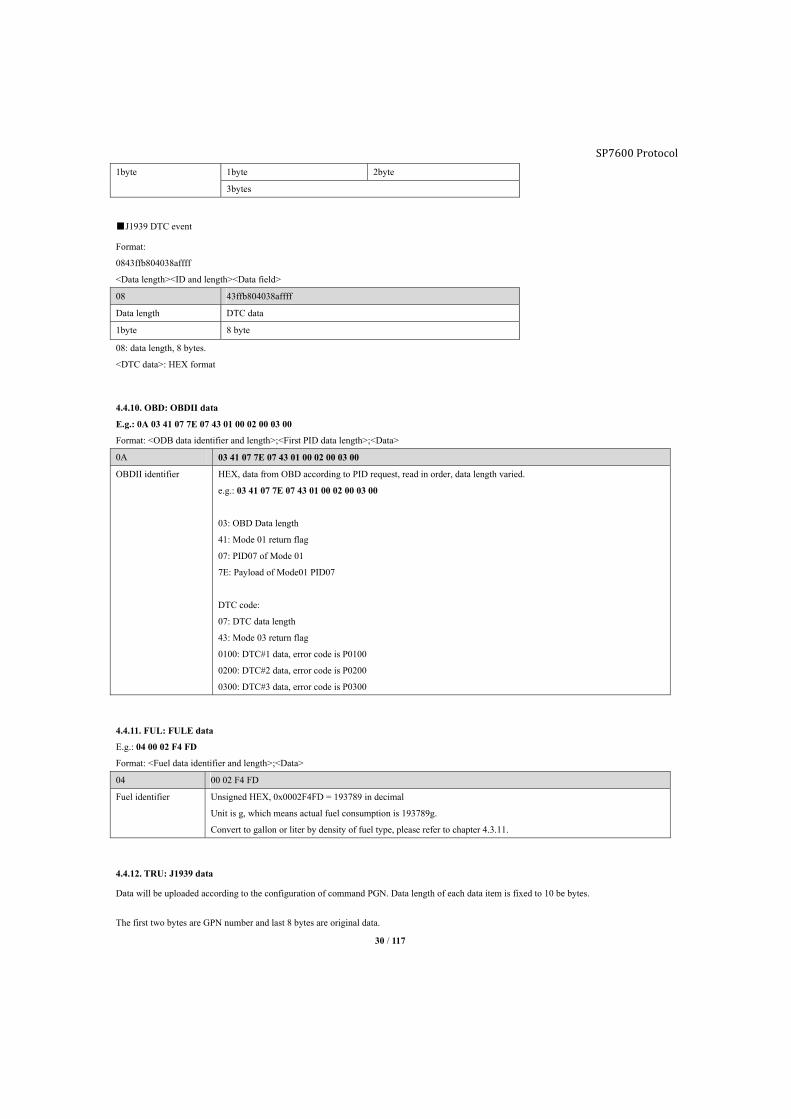
■J1939 DTC event
Format:
0843ffb804038affff
<Data length><ID and length><Data field>
08 43ffb804038affff
Data length DTC data
1byte 8 byte
08: data length, 8 bytes.
<DTC data>: HEX format
4.4.10. OBD: OBDII data
E.g.: 0A 03 41 07 7E 07 43 01 00 02 00 03 00
Format: <ODB data identifier and length>;<First PID data length>;<Data>
0A 03 41 07 7E 07 43 01 00 02 00 03 00
OBDII identifier HEX, data from OBD according to PID request, read in order, data length varied.
e.g.: 03 41 07 7E 07 43 01 00 02 00 03 00
03: OBD Data length
41: Mode 01 return flag
07: PID07 of Mode 01
7E: Payload of Mode01 PID07
DTC code:
07: DTC data length
43: Mode 03 return flag
0100: DTC#1 data, error code is P0100
0200: DTC#2 data, error code is P0200
0300: DTC#3 data, error code is P0300
4.4.11. FUL: FULE data
E.g.: 04 00 02 F4 FD
Format: <Fuel data identifier and length>;<Data>
04 00 02 F4 FD
Fuel identifier Unsigned HEX, 0x0002F4FD = 193789 in decimal
Unit is g, which means actual fuel consumption is 193789g.
Convert to gallon or liter by density of fuel type, please refer to chapter 4.3.11.
4.4.12. TRU: J1939 data
Data will be uploaded according to the configuration of command PGN. Data length of each data item is fixed to 10 be bytes.
The first two bytes are GPN number and last 8 bytes are original data.
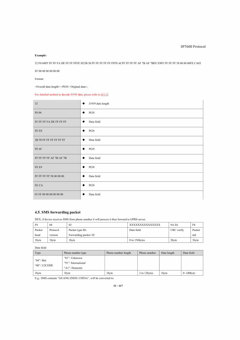
31 / 117
Example:
32 F0 04FF FF FF FA DE FF FF FFFE EE2B 50 FF FF FF FF FF FFFE 6CFF FF FF FF AF 7B AF 7BFE E9FF FF FF FF 58 00 00 00FE CA03
FF 00 00 00 00 00 00
Format:
<Overall data length>:<PGN+ Original data>,
For detailed method to decode J1939 data, please refer to 4.3.12
32 J1939 data length
F0 04 PGN
FF FF FF FA DE FF FF FF Data field
FE EE PGN
2B 50 FF FF FF FF FF FF Data field
FE 6C PGN
FF FF FF FF AF 7B AF 7B Data field
FE E9 PGN
FF FF FF FF 58 00 00 00 Data field
FE CA PGN
03 FF 00 00 00 00 00 00 Data field
4.5. SMS forwarding packet
HEX, if device receives SMS from phone number it will process it then forward to GPRS server.
F8 04 02 XXXXXXXXXXXXXXX 9A E6 F8
Packet
head
Protocol
version
Packet type ID,
Forwarding packet: 02
Data field CRC verify Packet
tail
1byte 1byte 1byte 0 to 156bytes 2byte 1byte
Data field
Type Phone number type Phone number length Phone number Data length Data field
“04”: 8bit
“08”: U2CODE
“81”: Unknown
“91”: International
“A1”: Domestic
1byte 1byte 1byte 2 to 12bytes 1byte 0~140byte
E.g.: SMS contents ”GUANG ZHOU CHINA”, will be converted to:
SP7600 Protocol
32 / 117
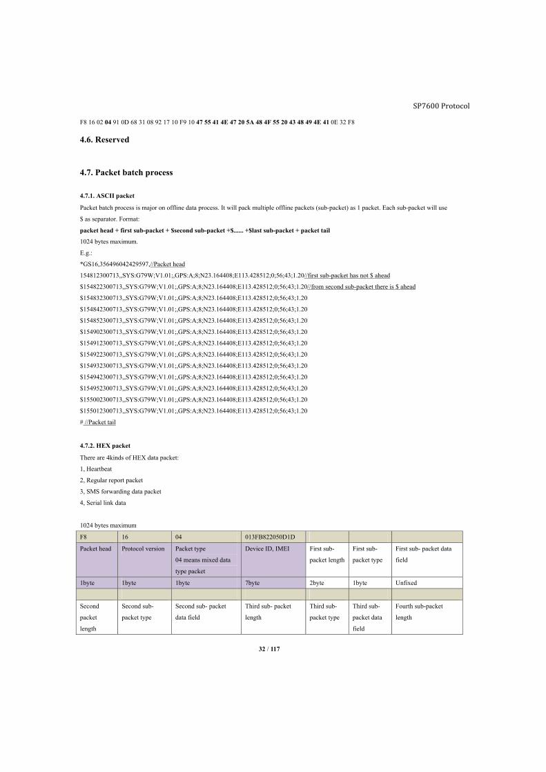
F8 16 02 04 91 0D 68 31 08 92 17 10 F9 10 47 55 41 4E 47 20 5A 48 4F 55 20 43 48 49 4E 41 0E 32 F8
4.6. Reserved
4.7. Packet batch process
4.7.1. ASCII packet
Packet batch process is major on offline data process. It will pack multiple offline packets (sub-packet) as 1 packet. Each sub-packet will use
$ as separator. Format:
packet head + first sub-packet + $second sub-packet +$...... +$last sub-packet + packet tail
1024 bytes maximum.
E.g.:
*GS16,356496042429597,//Packet head
154812300713,,SYS:G79W;V1.01;,GPS:A;8;N23.164408;E113.428512;0;56;43;1.20//first sub-packet has not $ ahead
$154822300713,,SYS:G79W;V1.01;,GPS:A;8;N23.164408;E113.428512;0;56;43;1.20//from second sub-packet there is $ ahead
$154832300713,,SYS:G79W;V1.01;,GPS:A;8;N23.164408;E113.428512;0;56;43;1.20
$154842300713,,SYS:G79W;V1.01;,GPS:A;8;N23.164408;E113.428512;0;56;43;1.20
$154852300713,,SYS:G79W;V1.01;,GPS:A;8;N23.164408;E113.428512;0;56;43;1.20
$154902300713,,SYS:G79W;V1.01;,GPS:A;8;N23.164408;E113.428512;0;56;43;1.20
$154912300713,,SYS:G79W;V1.01;,GPS:A;8;N23.164408;E113.428512;0;56;43;1.20
$154922300713,,SYS:G79W;V1.01;,GPS:A;8;N23.164408;E113.428512;0;56;43;1.20
$154932300713,,SYS:G79W;V1.01;,GPS:A;8;N23.164408;E113.428512;0;56;43;1.20
$154942300713,,SYS:G79W;V1.01;,GPS:A;8;N23.164408;E113.428512;0;56;43;1.20
$154952300713,,SYS:G79W;V1.01;,GPS:A;8;N23.164408;E113.428512;0;56;43;1.20
$155002300713,,SYS:G79W;V1.01;,GPS:A;8;N23.164408;E113.428512;0;56;43;1.20
$155012300713,,SYS:G79W;V1.01;,GPS:A;8;N23.164408;E113.428512;0;56;43;1.20
# //Packet tail
4.7.2. HEX packet
There are 4kinds of HEX data packet:
1, Heartbeat
2, Regular report packet
3, SMS forwarding data packet
4, Serial link data
1024 bytes maximum
F8 16 04 013FB822050D1D
Packet head Protocol version Packet type
04 means mixed data
type packet
Device ID, IMEI First sub-
packet length
First sub-
packet type
First sub- packet data
field
1byte 1byte 1byte 7byte 2byte 1byte Unfixed
Second
packet
length
Second sub-
packet type
Second sub- packet
data field
Third sub- packet
length
Third sub-
packet type
Third sub-
packet data
field
Fourth sub-packet
length
SP7600 Protocol
SP7600 Protocol
33 / 117
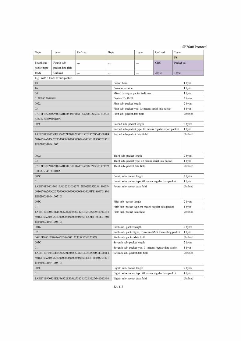
2byte 1byte Unfixed 2byte 1byte Unfixed 2byte
F8
Fourth sub-
packet type
Fourth sub-
packet data field
… … … CRC Packet tail
1byte Unfixed … … … 2byte 1byte
E.g.: with 3 kinds of sub-packet
F8 Packet head 1 byte
16 Protocol version 1 byte
04 Mixed data type packet indicator 1 byte
013FB822109948 Device ID, IMEI 7 bytes
0022 First sub- packet length 2 bytes
03 First sub- packet type, 03 means serial link packet 1 byte
07013FB8221099481ABE70F001016176A206C2C7303132333
43536373839300D0A
First sub- packet data field Unfixed
003C Second sub- packet length 2 bytes
01 Second sub- packet type, 01 means regular report packet 1 byte
1ABE70F100330E1556322E303627312E302E352D5413003F4
6016176A206C2C730000000000006009604056311860C01801
1E021003100410051
Second sub- packet data field Unfixed
0022 Third sub- packet length 2 bytes
03 Third sub- packet type, 03 means serial link packet 1 byte
07013FB8221099481ABE70F301016176A206C2C7303339323
33133353431330D0A
Third sub- packet data field Unfixed
003C Fourth sub- packet length 2 bytes
01 Fourth sub- packet type, 01 means regular data packet 1 byte
1ABE70FB00330E1556322E303627312E302E352D5413003F4
6016176A206C2C730000000000006009604054F11860C01801
1E02100310041005101
Fourth sub- packet data field Unfixed
003C Fifth sub- packet length 2 bytes
01 Fifth sub- packet type, 01 means regular data packet 1 byte
1ABE710500330E1556322E303627312E302E352D5413003F4
6016176A206C2C730000000000006009604055E11860C01801
1E02100310041005101
Firth sub- packet data field Unfixed
0016 Sixth sub- packet length 2 bytes
02 Sixth sub- packet type, 03 means SMS forwarding packet 1 byte
04910D683129461465F00A30313233343536373839 Sixth sub- packet data field Unfixed
003C Seventh sub- packet length 2 bytes
01 Seventh sub- packet type, 01 means regular data packet 1 byte
1ABE710F00330E1556322E303627312E302E352D5413003F4
6016176A206C2C730000000000006009604056111860C01801
1E02100310041005101
Seventh sub- packet data field Unfixed
003C Eighth sub- packet length 2 bytes
01 Eighth sub- packet type, 01 means regular data packet 1 byte
1ABE711900330E1556322E303627312E302E352D5413003F4 Eighth sub- packet data field Unfixed
34 / 117
6016176A206C2C730000000000006009604054F11860C01801
1E02100310041005101
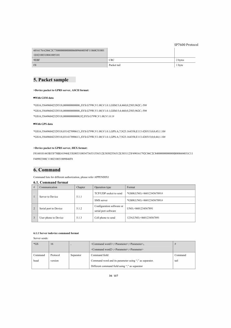
9EBF CRC 2 bytes
F8 Packet tail 1 byte
5. Packet sample
>Device packet to GPRS server, ASCII format:
■With GSM data
*GS16,356496042329318,000000000000,,SYS:G79W;V1.00;V1.0.1,GSM:5;4;460;0;2503;962C;-59#
*GS16,356496042329318,000000000000,,SYS:G79W;V1.00;V1.0.1,GSM:5;4;460;0;2503;962C;-59#
*GS16,356496042329318,000000000000,92,SYS:G79W;V1.00;V1.0.1#
■With GPS data
*GS16,356496042329318,031427090613,,SYS:G79W;V1.00;V1.0.1,GPS:A;7;N23.164358;E113.428515;0;0;45;1.10#
*GS16,356496042329318,031417090613,,SYS:G79W;V1.00;V1.0.1,GPS:A;7;N23.164358;E113.428515;0;0;44;1.10#
>Device packet to GPRS server, HEX format:
F8160101443B33F78BE41946E33E003310034736531556312E30302556312E3031123F490161792C06C2C84000000000008B008604031C11
F40902308C1180210031009846F8
6. Command
Command lists for different authorization, please refer APPENDIX1
6.1. Command format # Communication Chapter Operation type Format
1 Server to Device 5.1.1 TCP/UDP socket to send *GS00,UNO;+8601234567891#
SMS server *GS00,UNO;+8601234567891#
2 Serial port to Device 5.1.2 Configuration software or
serial port software UNO;+8601234567891
3 User phone to Device 5.1.3 Cell phone to send 1234,UNO;+8601234567891
6.1.1 Server todevice command format
Server sends:
*GS 16 , <Command word1>;<Parameter>;<Parameter>,
<Command word2>;<Parameter>;<Parameter>
#
Command
head
Protocol
version
Separator Command field:
Command word and its parameter using “;” as separator.
Different command field using “,” as separator
Command
tail
SP7600 Protocol

SP7600 Protocol
35 / 117
Device replies:
*GS 16 , 358696040652862 , <Command
word>:<Parameter>;<Parameter>,<Comman
d word>:<Parameter>;<Parameter>
#
Packet
head
Protocol
version
Separator Device ID Separator Command field Packet
tail
e.g.:
Send: *GS00,UNO;13912345678#
Reply: *GS16,358696040652862,UNO:13912345678#
6.1.2 Serial port to device command format
Send Reply
<Command word>;<Parameter>;<Parameter> <Command word>:<Parameter>;<Parameter>
Command field:
Separator is “;”
Command field:
Separator between command word and parameter using “:” as
separator,
Parameters in identical command word using “;” as separator.
e.g.:
Send: UNO;13912345678
Reply: UNO:13912345678
6.1.3 User phone to device command format
1234 , <Command word>;<Parameter>;<Parameter>
Password Separator Command field
Command field
Command word and its parameter using “;” as separator.
Different command field using “,” as separator
Send: 1234,UPW;1234
Reply: G79W V1.00
UPW:1234
EXT_PWR=11.94V
BAT=3.90V
#3
6.1.4 Command combination
■Multiple commands to send in one message, length 256 maximum.
Server to device
Between different command using “,” as separator
e.g.:
Send: *GS00,UNO;13912345678,UPW;1234#
Reply: *GS16,0123456789,UNO:13912345678,UPW:1234#
User phone to device
Between different commands using “,” as separator

SP7600 Protocol
36 / 117
e.g.:
Send:1234,UNO;13912345678,UPW;4567
Reply: G79W V1.00
UNO:13912345678
UPW:1234
EXT_PWR=11.94V
BAT=3.90V
#3
Computer to device
Between different command using “,” as separator
Send:
UNO;13912345678,UPW;1234
Reply:
UNO:13912345678,UPW:1234
6.2. OEM command Format:
Send : *GS00,UCM;FFFF#
Reply: *GS16,358696040652862,UCM:FFFF#
6.2.1 Reset to factory default (DFP)
Command word Format Reply
DFP DFP DFP
Explanation Device configuration will be reset
6.2.2 Set OEM password (OPW)
Command word Format Reply
OPW OPW;0123456789 OPW:0123456789
OPW OPW:0123456789
Explanation OPW;<PASSWORD>
This password is for the accessibility of configuration software on computer.
Length is 10 digits fixed.
Default password: 0123456789
6.2.3 Administrator command mask (ACM)
Command word Format Reply
ACM ACM;1F8 ACM:1F8
ACM ACM:1F8
SP7600 Protocol
37 / 117
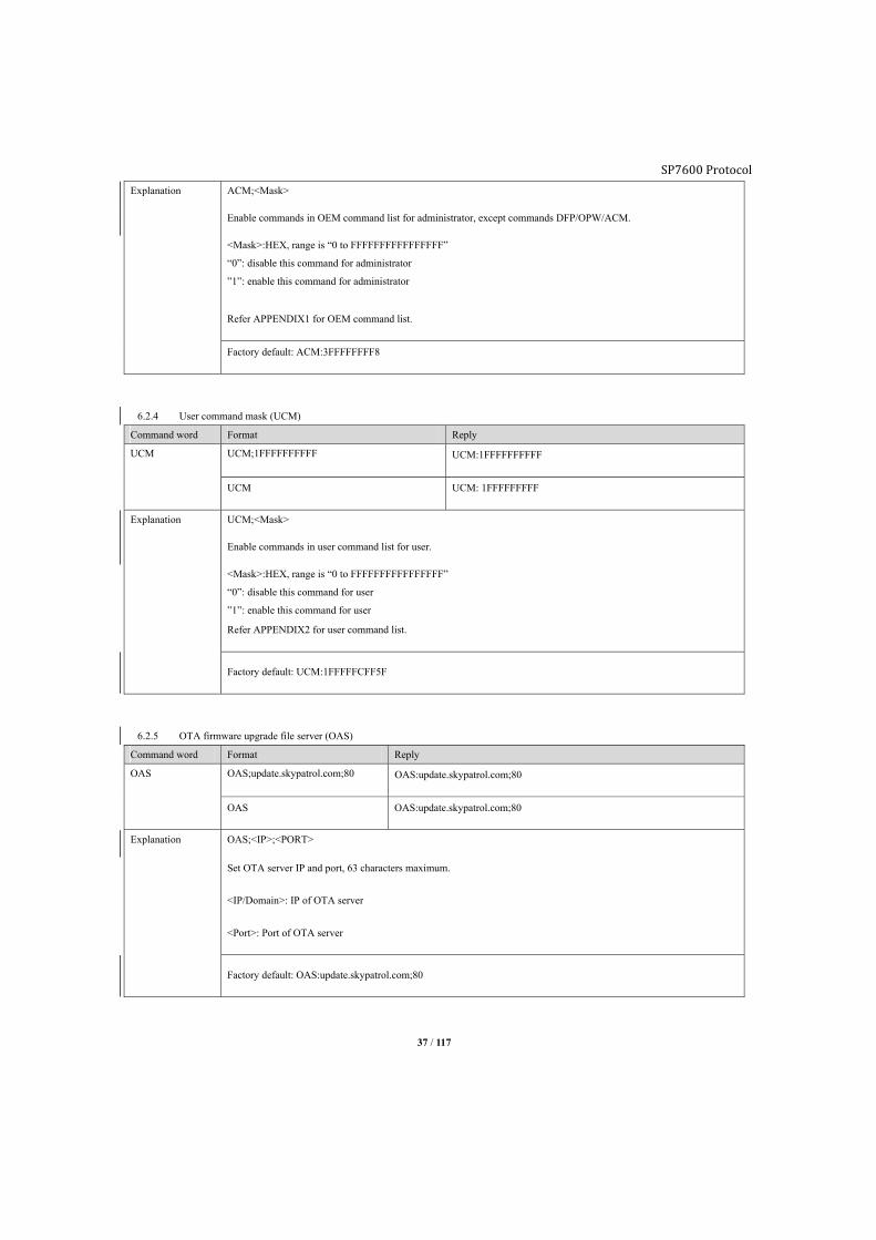
Explanation ACM;<Mask>
Enable commands in OEM command list for administrator, except commands DFP/OPW/ACM.
<Mask>:HEX, range is “0 to FFFFFFFFFFFFFFFF”
“0”: disable this command for administrator
”1”: enable this command for administrator
Refer APPENDIX1 for OEM command list.
Factory default: ACM:3FFFFFFFF8
6.2.4 User command mask (UCM)
Command word Format Reply
UCM UCM;1FFFFFFFFFF UCM:1FFFFFFFFFF
UCM UCM: 1FFFFFFFFF
Explanation UCM;<Mask>
Enable commands in user command list for user.
<Mask>:HEX, range is “0 to FFFFFFFFFFFFFFFF”
“0”: disable this command for user
”1”: enable this command for user
Refer APPENDIX2 for user command list.
Factory default: UCM:1FFFFFCFF5F
6.2.5 OTA firmware upgrade file server (OAS)
Command word Format Reply
OAS OAS;update.skypatrol.com;80 OAS:update.skypatrol.com;80
OAS OAS:update.skypatrol.com;80
Explanation OAS;<IP>;<PORT>
Set OTA server IP and port, 63 characters maximum.
<IP/Domain>: IP of OTA server
<Port>: Port of OTA server
Factory default: OAS:update.skypatrol.com;80

SP7600 Protocol
38 / 117
6.2.6 OTA firmware file pathand (OAP)
Command word Format Reply
OAP OAP;/skypatrol/G6S/V105/Release/G6S.txt
OAP1;/skypatrol/OBD/Release/OBDII.txt
OAP:/skypatrol/G6S/V105/Release/G6S.txt
OAP1:/skypatrol/OBD/Release/OBDII.txt
OAP
OAP1
OAP:/skypatrol/G6S/V105/Release/G6S.txt
OAP1:/skypatrol/OBD/Release/OBDII.txt
Explanation This command is to set file path for MCU firmware and OBDII chip firmware
OAP;<MCU firmware file path>
OAP1;<OBDII chip firmware file path>
<File path>:
64bytes maximum, OTA file path on OTA server
Factory default: OAP:/skypatrol/G6S/Release/G6S.txt
OAP1:/skypatrol/OBD/Release/OBDII.txt
6.2.7 APN information list (APL)
Command word Format Reply
APL APL;46000;cmnet;user;pw APL:46000;cmnet;user;pw
APL;46000 APL:46000;cmnet;user;pw
Explanation Device is able to save APN list on device, when SIM card inserted to automatically fulfill APN information.
There is 4K byte memory is used for APN list.
Device will keep the newest APN in memory.
APL;<MCC+MNC>;<APN>;<user name>;<pw>
<MCC+MNC>: 3 digits for country code, 2 or 3 digits for carrier code
<APN>: APN name, maximum 64 bytes
<user name>: User name for APN
<pw>: password for APN
Factory default: Chinese APN
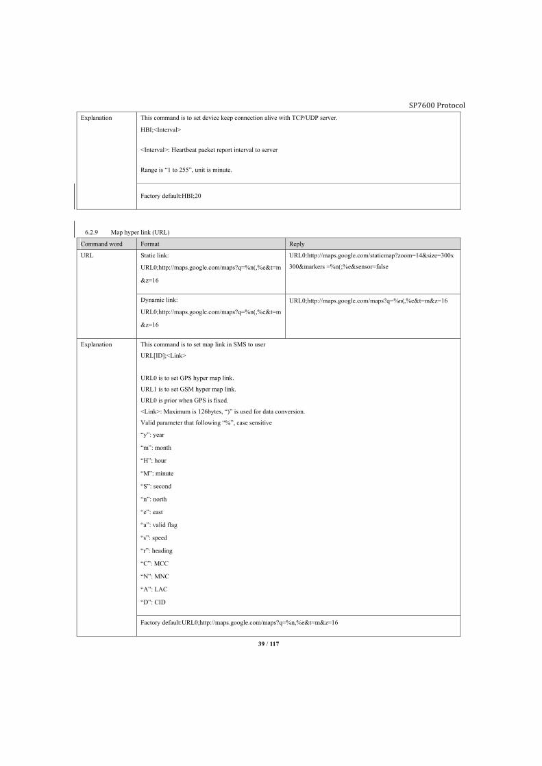
6.2.8 Heartbeat packet (HBI)
Command word Format Reply
HBI HBI;50 HBI:50
HBI HBI:50
SP7600 Protocol
39 / 117
Explanation This command is to set device keep connection alive with TCP/UDP server.
HBI;<Interval>
<Interval>: Heartbeat packet report interval to server
Range is “1 to 255”, unit is minute.
Factory default:HBI;20
6.2.9 Map hyper link (URL)
Command word Format Reply
URL Static link:
URL0;http://maps.google.com/maps?q=%n(,%e&t=m
&z=16
URL0:http://maps.google.com/staticmap?zoom=14&size=300x
300&markers =%n(;%e&sensor=false
Dynamic link:
URL0;http://maps.google.com/maps?q=%n(,%e&t=m
&z=16
URL0;http://maps.google.com/maps?q=%n(,%e&t=m&z=16
Explanation This command is to set map link in SMS to user
URL[ID];<Link>
URL0 is to set GPS hyper map link.
URL1 is to set GSM hyper map link.
URL0 is prior when GPS is fixed.
<Link>: Maximum is 126bytes, “)” is used for data conversion.
Valid parameter that following “%”, case sensitive
“y”: year
“m”: month
“H”: hour
“M”: minute
“S”: second
“n”: north
“e”: east
“a”: valid flag
“s”: speed
“r”: heading
“C”: MCC
“N”: MNC
“A”: LAC
“D”: CID
Factory default:URL0;http://maps.google.com/maps?q=%n,%e&t=m&z=16
SP7600 Protocol
40 / 117
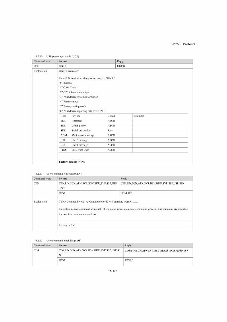
6.2.10 USB port output mode (UGP)
Command word Format Reply
UGP UGP;0 UGP:0
Explanation UGP;<Parameter>
To set USB output working mode, range is “0 to 6”.
“0”: Normal
“1”:GSM Trace
“2”:GPS information output
“3”:Print device system information
“4”:Factory mode
“5”:Factory testing mode
“6”:Print device reporting data over GPRS
Head Payload Coded Example
SER: Heartbeat ASCII
SER: GPRS packet ASCII
SER: Serial link packet Raw
ADM: SMS server message ASCII
US0: User0 message ASCII
US1: User1 message ASCII
PRQ: SMS from User ASCII
Factory default:UGP;0
6.2.11 User command white list (CEN)
Command word Format Reply
CEN CEN;PIN;SCN;APN;SVR;BSV;BDU;SVP;SSP;USP
;SSN
CEN:PIN;SCN;APN;SVR;BSV;BDU;SVP;SSP;USP;SSN
UCM UCM;3FF
Explanation CEN;<Command word1>;<Command word2>;<Command word3>……..
To customize user command white list, 10 command words maximum, command words in this command are available
for user from admin command list
Factory default:
6.2.12 User command black list (CDS)
Command word Format Reply
CDS CDS;PIN;SCN;APN;SVR;BSV;BDU;SVP;SSP;USP;SS
N CDS:PIN;SCN;APN;SVR;BSV;BDU;SVP;SSP;USP;SSN
UCM UCM;0

SP7600 Protocol
41 / 117
Explanation CDS;<Command word1>;<Command word2>;<Command word3>…
Opposite to command CEN, this command is used to forbidden commands for user from admin list.
CDS;PIN;SCN;APN;SVR;BSV;BDU;SVP;SSP;USP;SSN
CDS:PIN;SCN;APN;SVR;BSV;BDU;SVP;SSP;USP;SSN
UCM
UCM:0
Factory default:
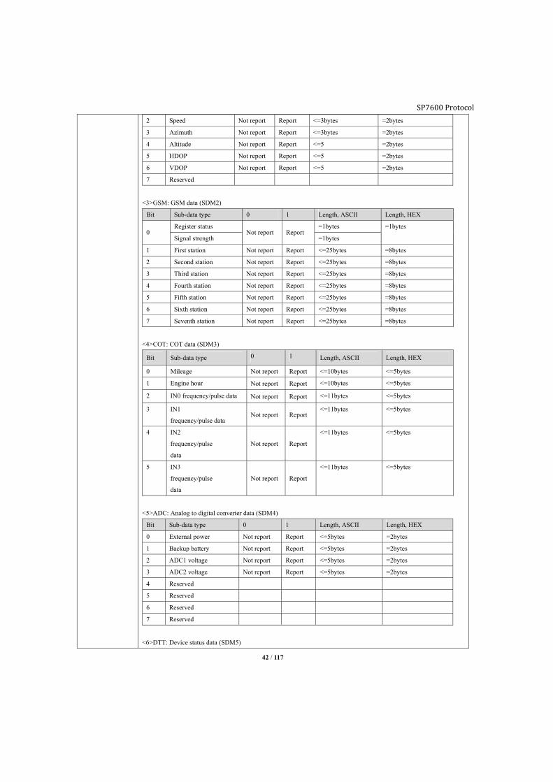
6.2.13 Sub-data type mask (SDM)
Command word Format Reply
SDM SDM1;FFFF SDM1:7F
SDM1 SDM1:7F
Explanation To set Sub-data type mask.
Format:
SDM[Main data identifier]; <Sub-data type mask>
<Main data identifier>: range is “0 to 15”, refer command AMD “Main data type list”.
<Sub-data mask>:
HEX, range is “0000 to FFFF”.
“0” means not report.
“1” means report.
<1>SYS: System data mask (SDM0)
Bit Sub-data type 0 1 Length, ASCII Length, HEX
0 Device name Not report Report <=15bytes <=15bytes
1 Firmware version Not report Report <=8bytes <=8bytes
2 Hardware
version Not report Report
<=8bytes <=8bytes
<2>GPS: GPS data mask (SDM1)
Bit Sub-data type 0 1 Length, ASCII Length, HEX
0 Fix flag
Not report Report =1bytes =1byte
Valid satellite number <=2bytes
1 Latitude
Not report Report 10bytes =8bytes
Longitude 11bytes
SP7600 Protocol
42 / 117
2 Speed Not report Report <=3bytes =2bytes
3 Azimuth Not report Report <=3bytes =2bytes
4 Altitude Not report Report <=5 =2bytes
5 HDOP Not report Report <=5 =2bytes
6 VDOP Not report Report <=5 =2bytes
7 Reserved
<3>GSM: GSM data (SDM2)
Bit Sub-data type 0 1 Length, ASCII Length, HEX
0 Register status
Not report Report =1bytes =1bytes
Signal strength =1bytes
1 First station Not report Report <=25bytes =8bytes
2 Second station Not report Report <=25bytes =8bytes
3 Third station Not report Report <=25bytes =8bytes
4 Fourth station Not report Report <=25bytes =8bytes
5 Fifth station Not report Report <=25bytes =8bytes
6 Sixth station Not report Report <=25bytes =8bytes
7 Seventh station Not report Report <=25bytes =8bytes
<4>COT: COT data (SDM3)
Bit Sub-data type 0 1 Length, ASCII Length, HEX
0 Mileage Not report Report <=10bytes <=5bytes
1 Engine hour Not report Report <=10bytes <=5bytes
2 IN0 frequency/pulse data Not report Report <=11bytes <=5bytes
3 IN1
frequency/pulse data Not report Report
<=11bytes <=5bytes
4 IN2
frequency/pulse
data
Not report Report
<=11bytes <=5bytes
5 IN3
frequency/pulse
data
Not report Report
<=11bytes <=5bytes
<5>ADC: Analog to digital converter data (SDM4)
Bit Sub-data type 0 1 Length, ASCII Length, HEX
0 External power Not report Report <=5bytes =2bytes
1 Backup battery Not report Report <=5bytes =2bytes
2 ADC1 voltage Not report Report <=5bytes =2bytes
3 ADC2 voltage Not report Report <=5bytes =2bytes
4 Reserved
5 Reserved
6 Reserved
7 Reserved
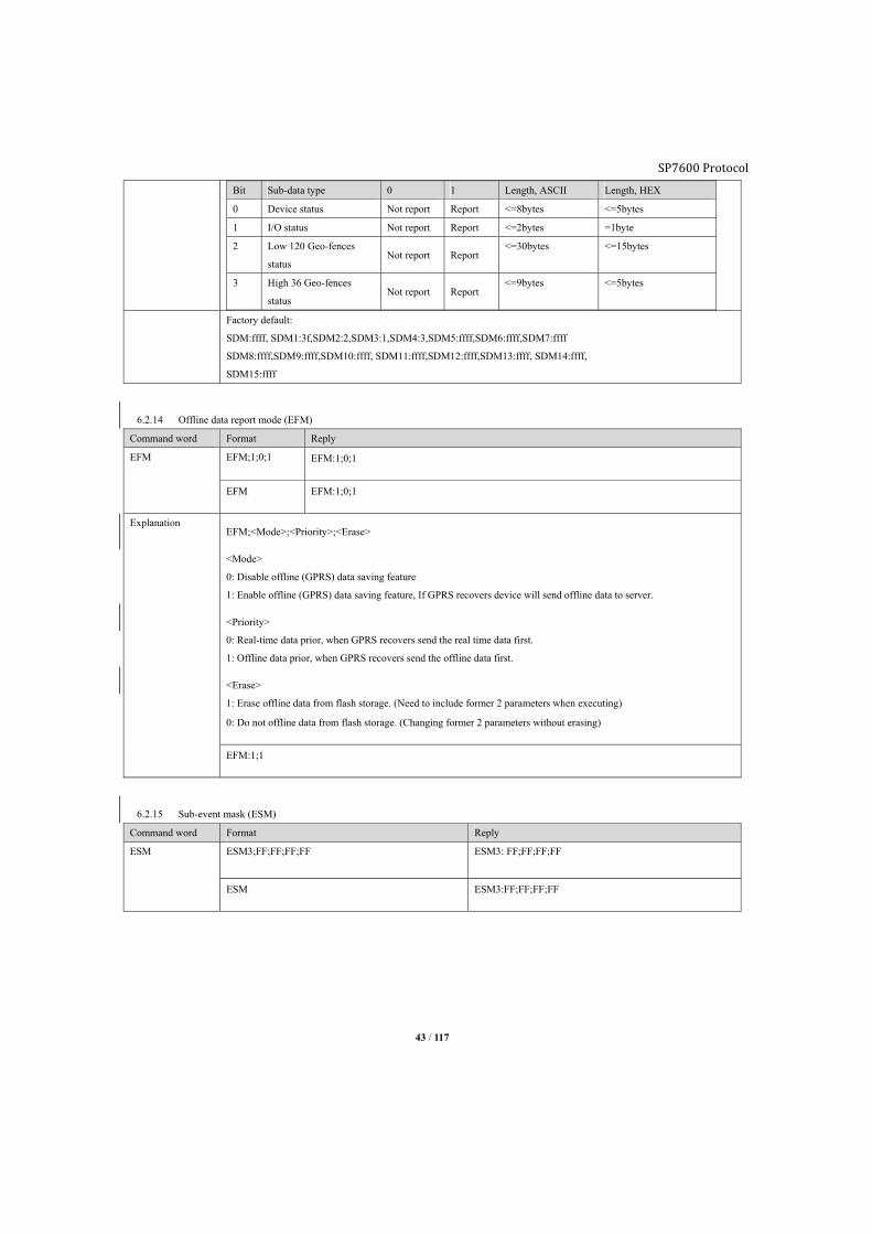
<6>DTT: Device status data (SDM5)
SP7600 Protocol
43 / 117
Bit Sub-data type 0 1 Length, ASCII Length, HEX
0 Device status Not report Report <=8bytes <=5bytes
1 I/O status Not report Report <=2bytes =1byte
2 Low 120 Geo-fences
status Not report Report
<=30bytes <=15bytes
3 High 36 Geo-fences
status Not report Report
<=9bytes <=5bytes
Factory default:
SDM:ffff, SDM1:3f,SDM2:2,SDM3:1,SDM4:3,SDM5:ffff,SDM6:ffff,SDM7:ffff
SDM8:ffff,SDM9:ffff,SDM10:ffff, SDM11:ffff,SDM12:ffff,SDM13:ffff, SDM14:ffff,
SDM15:ffff
6.2.14 Offline data report mode (EFM)
Command word Format Reply
EFM EFM;1;0;1 EFM:1;0;1
EFM EFM:1;0;1
Explanation EFM;<Mode>;<Priority>;<Erase>
<Mode>
0: Disable offline (GPRS) data saving feature
1: Enable offline (GPRS) data saving feature, If GPRS recovers device will send offline data to server.
<Priority>
0: Real-time data prior, when GPRS recovers send the real time data first.
1: Offline data prior, when GPRS recovers send the offline data first.
<Erase>
1: Erase offline data from flash storage. (Need to include former 2 parameters when executing)
0: Do not offline data from flash storage. (Changing former 2 parameters without erasing)
EFM:1;1
6.2.15 Sub-event mask (ESM)
Command word Format Reply
ESM ESM3;FF;FF;FF;FF ESM3: FF;FF;FF;FF
ESM ESM3:FF;FF;FF;FF
SP7600 Protocol
44 / 117
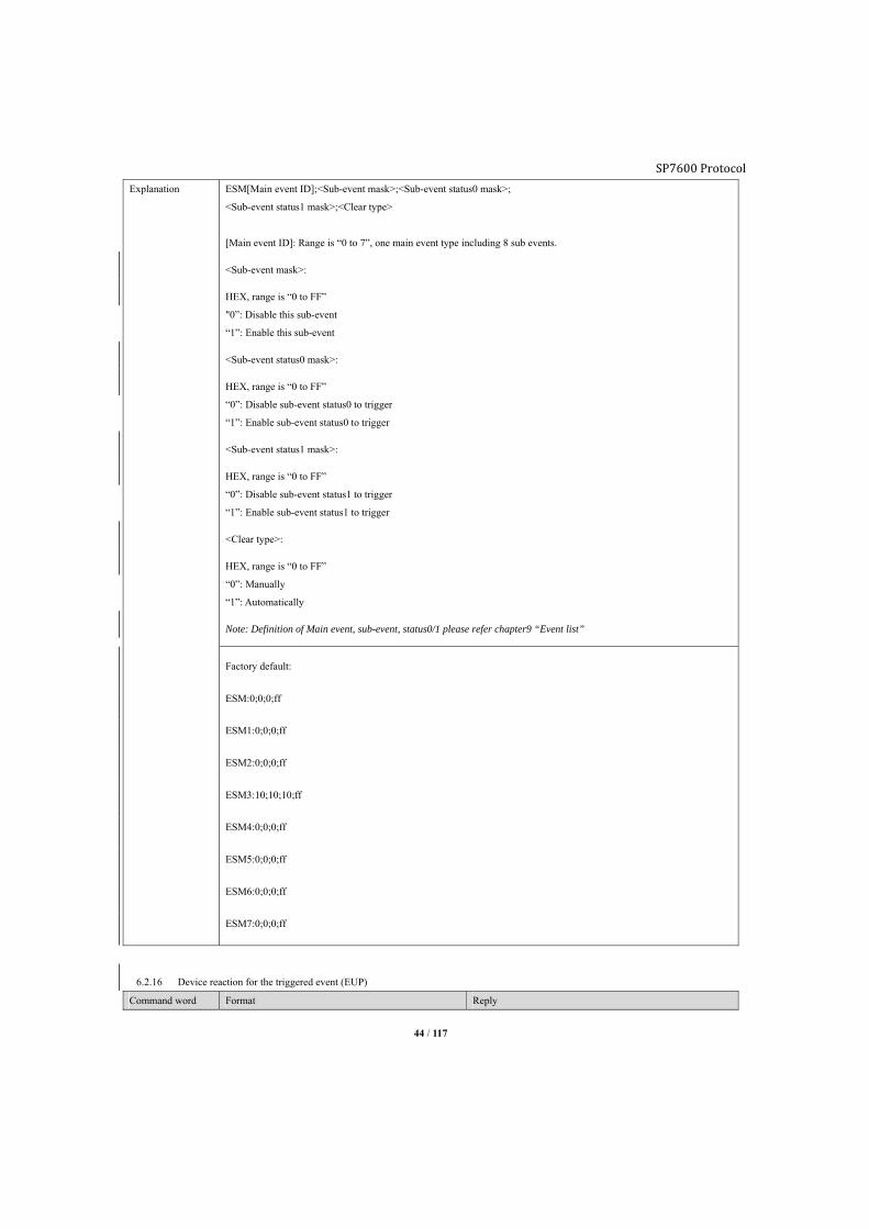
Explanation ESM[Main event ID];<Sub-event mask>;<Sub-event status0 mask>;
<Sub-event status1 mask>;<Clear type>
[Main event ID]: Range is “0 to 7”, one main event type including 8 sub events.
<Sub-event mask>:
HEX, range is “0 to FF”
"0”: Disable this sub-event
“1”: Enable this sub-event
<Sub-event status0 mask>:
HEX, range is “0 to FF”
“0”: Disable sub-event status0 to trigger
“1”: Enable sub-event status0 to trigger
<Sub-event status1 mask>:
HEX, range is “0 to FF”
“0”: Disable sub-event status1 to trigger
“1”: Enable sub-event status1 to trigger
<Clear type>:
HEX, range is “0 to FF”
“0”: Manually
“1”: Automatically
Note: Definition of Main event, sub-event, status0/1 please refer chapter9 “Event list”
Factory default:
ESM:0;0;0;ff
ESM1:0;0;0;ff
ESM2:0;0;0;ff
ESM3:10;10;10;ff
ESM4:0;0;0;ff
ESM5:0;0;0;ff
ESM6:0;0;0;ff
ESM7:0;0;0;ff
6.2.16 Device reaction for the triggered event (EUP)
Command word Format Reply
SP7600 Protocol
45 / 117
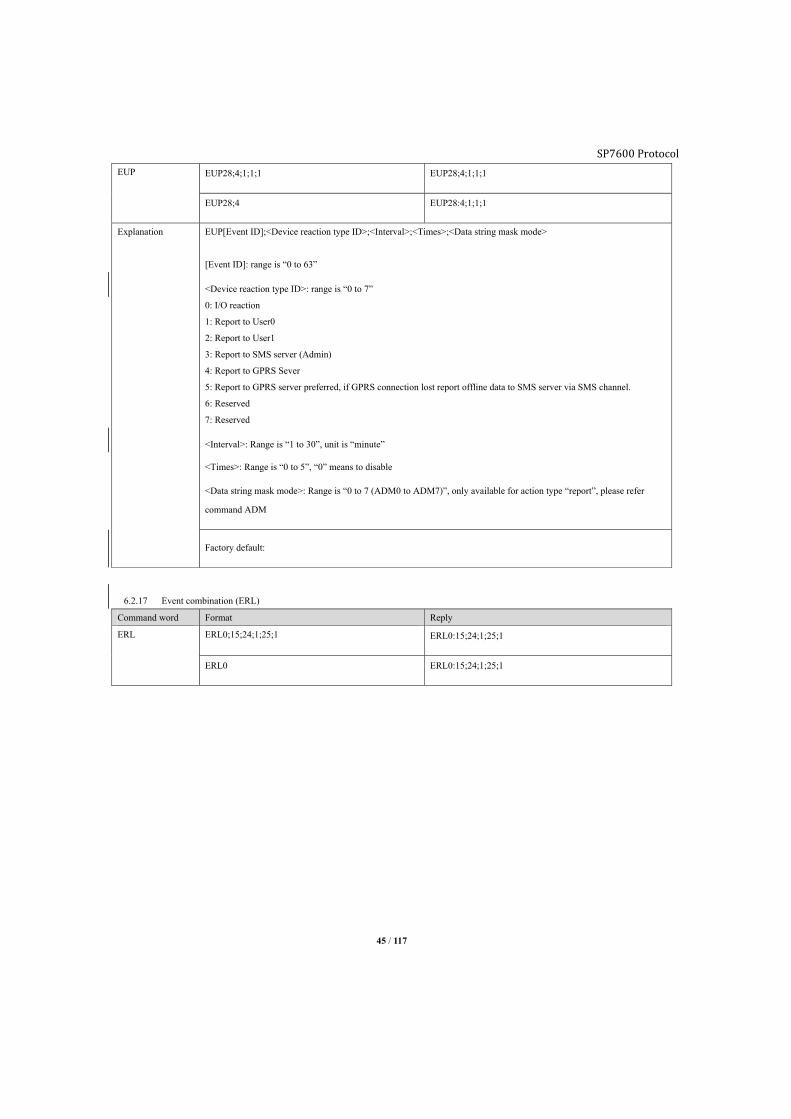
EUP EUP28;4;1;1;1 EUP28;4;1;1;1
EUP28;4 EUP28:4;1;1;1
Explanation EUP[Event ID];<Device reaction type ID>;<Interval>;<Times>;<Data string mask mode>
[Event ID]: range is “0 to 63”
<Device reaction type ID>: range is “0 to 7”
0: I/O reaction
1: Report to User0
2: Report to User1
3: Report to SMS server (Admin)
4: Report to GPRS Sever
5: Report to GPRS server preferred, if GPRS connection lost report offline data to SMS server via SMS channel.
6: Reserved
7: Reserved
<Interval>: Range is “1 to 30”, unit is “minute”
<Times>: Range is “0 to 5”, “0” means to disable
<Data string mask mode>: Range is “0 to 7 (ADM0 to ADM7)”, only available for action type “report”, please refer
command ADM
Factory default:
6.2.17 Event combination (ERL)
Command word Format Reply
ERL ERL0;15;24;1;25;1 ERL0:15;24;1;25;1
ERL0 ERL0:15;24;1;25;1
SP7600 Protocol
46 / 117
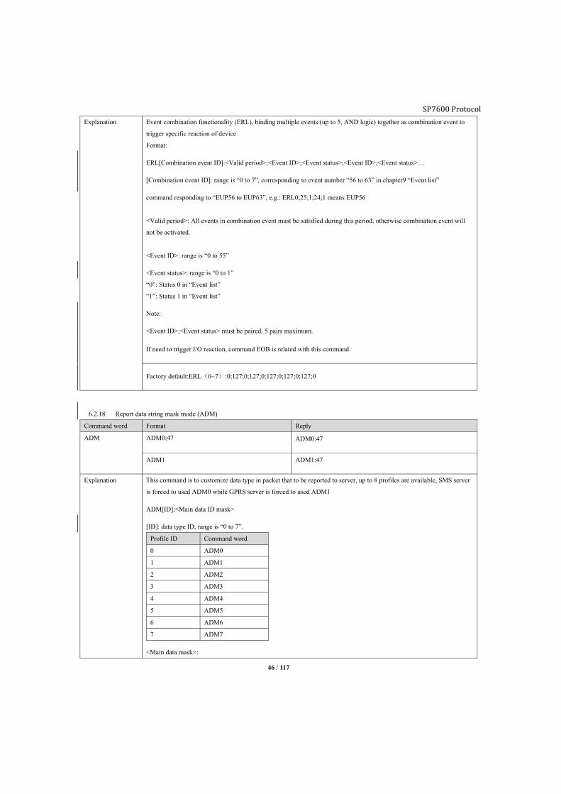
Explanation Event combination functionality (ERL), binding multiple events (up to 5, AND logic) together as combination event to
trigger specific reaction of device
Format:
ERL[Combination event ID]:<Valid period>;<Event ID>;<Event status>;<Event ID>;<Event status>…
[Combination event ID]: range is “0 to 7”, corresponding to event number “56 to 63” in chapter9 “Event list”
command responding to “EUP56 to EUP63”, e.g.: ERL0;25;1;24;1 means EUP56
<Valid period>: All events in combination event must be satisfied during this period, otherwise combination event will
not be activated.
<Event ID>: range is “0 to 55”
<Event status>: range is “0 to 1”
“0”: Status 0 in “Event list”
“1”: Status 1 in “Event list”
Note:
<Event ID>;<Event status> must be paired, 5 pairs maximum.
If need to trigger I/O reaction, command EOB is related with this command.
Factory default:ERL(0~7):0;127;0;127;0;127;0;127;0;127;0
6.2.18 Report data string mask mode (ADM)
Command word Format Reply
ADM ADM0;47 ADM0:47
ADM1 ADM1:47
Explanation This command is to customize data type in packet that to be reported to server, up to 8 profiles are available, SMS server
is forced to used ADM0 while GPRS server is forced to used ADM1
ADM[ID];<Main data ID mask>
[ID]: data type ID, range is “0 to 7”.
Profile ID Command word
0 ADM0
1 ADM1
2 ADM2
3 ADM3
4 ADM4
5 ADM5
6 ADM6
7 ADM7
<Main data mask>:

SP7600 Protocol
47 / 117
HEX, range is “0 to FFFF”.
“0”: Not report this kind of data
“1”: Report this kind of data
Main data ID mask
Main data mask (Bit) Main data ID Explanation 0 1
0 SYS System data Not report Report
1 GPS GPS data Not report Report
2 GSM GSM data Not report Report
3 COT COT data Not report Report
4 ADC ADC data Not report Report
5 DTT Device status data Not report Report
6 Reserved Reserved Not report Report
7 ETD Event data Not report Report
8 OBD OBDII data Not report Report
9 FUL Fuel consumption Not report Report
10 TRU J1939 data Not report Report
11 Reserved Reserved
12 Reserved Reserved
13 Reserved Reserved
14 Reserved Reserved
15 Reserved Reserved
Note:
Command ADM0 is specific for non-event report to SMS server, data string maximum length is 230bytes.
Command ADM1 is specific for non-event report to GPRS server, data string length is 384bytes.
“Bit0” and “Bit1” are fixed as “1”, which means data string must including GPS or GSM information. Packet including
GSM data is according to report setting SVR/SSP/USP, e.g. G mode when GPS preferred, otherwise use GSM data, A
mode GPS and GSM both will be reported to server.

SP7600 Protocol
48 / 117
Factory default:
ADM0:47
ADM1:47
ADM2:47
ADM3:47
ADM4:47
ADM5:47
ADM6:47
ADM7:47
6.2.19 Harsh behavior configuration (BMS)
Command word Format Reply
BMS BMS;2;10;45;35;40;30 BMS:2;10;45;35;40;30
BMS BMS:2;10;45;35;40;30
Explanation BMS;<moving_para>;<harsh_brake_para>;<harsh_accelerate_para>;<harsh_corner_left_para>;<harsh_corner_right_par
a>
<moving_para>:
Device motion status acceleration magnitude threshold, range is “1 to 200”, unit is 0.01g.
<harsh_brake_para>:
Device harsh brake acceleration magnitude threshold, range is “1 to 200”, unit is 0.01g.
<harsh_accelerate_para>:
Device harsh accelerates acceleration magnitude threshold, range is “1 to 200”, unit is 0.01g.
<harsh_corner_left_para>:
Device harsh left cornering acceleration magnitude threshold, range is “1 to 200”, unit is 0.01g.
<harsh_corner_right_para>
Device harsh right cornering acceleration magnitude threshold, range is “1 to 200”, unit is 0.01g.
Default: BMS:2;10;45;35;40;30
6.2.20 Accident detection configuration (AMS)

SP7600 Protocol
49 / 117
Command word Format Reply
AMS AMS;150;90 AMS:150;90
AMS AMS:150;90
Explanation AMS;<crash_para>;<trun_over_para>
<crash_para>:
Crash (collision) acceleration magnitude threshold, range is “1 to 200”, unit is 0.01g.
Note: Sensor itself will judge front or rear collision, side collision will be considered as rear.
<trun_over_para>:
Turn over acceleration magnitude threshold, range is “1 to 200”, unit is 0.01g.
Default: AMS:150;90
6.2.21 Geo-fence mask (UFM)
Command word Format Reply
UFM UFM;FFFFFFFFFFFFFFFFFFFFFFFFFFFFFFFFFFFFFFF UFM:FFFFFFFFFFFFFFFFFFFFFFFFFFFFFFFFFFFFFFF
UFM UFM:FFFFFFFFFFFFFFFFFFFFFFFFFFFFFFFFFFFFFFF
Explanation UFM;<use_mask>
<use_mask>:
User Geo-fence mask, 156 Geo-fences in total (0 - 155), Bit0 – Bit27, Bit28 – Bit159.
“0”: Disable this geo fence for user
“1”: Enable this geo fence for user
Default: UFM:1
6.2.22 A-GPS configuration (AGS)
Command word Format Reply
AGS AGS;[email protected];Moouaq AGS:[email protected];Moouaq
AGS AGS:[email protected];Moouaq
Explanation This command is to set username and password to connect with AGPS server.
<Username>:48 characters maximum.
<Password>:12 characters maximum
Default: AGS;[email protected];Moouaq
6.2.23 Power saving mode configuration (PSS)

SP7600 Protocol
50 / 117
Command word Format Reply
PSS PSS0;0 PSS0:0
PSS0 PSS0:0
Explanation PSS<Module>;<Toggle>;<Para1>;<Para2>;<Para3>
<Module>
Value Explanation
0 GSM module
1 GPS module
2 3D accelerate sensor
<Toggle>:
“0” disable power saving
“1” enable power saving
■GSM module:
PSS0;1;<para1>;<para2>;<para3>
<para1>: Unregistered duration time threshold,unit is minute, range is “1 to 255”
<para2>: No data transmission duration time threshold,unit is minute, range is “1 to 255”
<para3>: Awake interval, unit is minute, range is “1 to 65535”
■GPS module
PSS1;1;<para1>;<para2>
<para1>: GPS un-fixed duration time threshold, unit is minute, range is “1 to 255”
<para2>: Awake interval,unit is minute, range is “1 to 65535”
■3D accelerate sensor module
PSS2;<Toggle>
If GSM unregistered duration surpasses threshold time or no data transmission duration surpasses threshold time, power
saving will be activated. Under power saving if device detects data transmit request and able to establish socket
connection before, it will wake up instantly; otherwise device wakes up according to awaken interval.
If GPS un-fixed duration surpasses threshold time or under parking status, power saving will be activated.
Before activation if GPS un-fixed, device will wakes up according to awake interval, otherwise it will wake up when
vehicle leaves parking status.
If GSM and GPS both under power saving, MCU will go to power saving as well.
Default:
PSS0;0
PSS1;1;5;10
PSS2;0
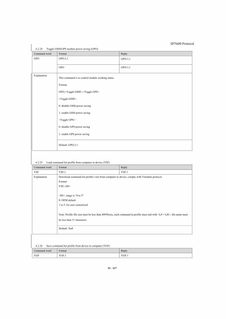
SP7600 Protocol
51 / 117
6.2.24 Toggle GSM/GPS module power saving (GPO)
Command word Format Reply
GPO GPO;1;1 GPO:1;1
GPO GPO:1;1
Explanation This command is to control module working status.
Format:
GPO;<Toggle GSM>;<Toggle GPS>
<Toggle GSM>:
0: disable GSM power saving
1: enable GSM power saving
<Toggle GPS>:
0: disable GPS power saving
1: enable GPS power saving
Default: GPO;1;1
6.2.25 Load command list profile from computer to device (YSF)
Command word Format Reply
YSF YSF;1 YSF:1
Explanation Download command list profile (.txt) from computer to device, comply with Ymodem protocol.
Format:
YSF;<ID>
<ID>: range is “0 to 5”
0: OEM default
1 to 5: for user customized
Note: Profile file size must be less than 4095bytes, each command in profile must end with <LF><LR>, file name must
be less than 31 characters.
Default: Null
6.2.26 Save command list profile from device to computer (YGF)
Command word Format Reply
YGF YGF;1 YGF:1

SP7600 Protocol
52 / 117
Explanation Download command list profile from device to computer, complying Ymodem protocol
Format: YGF;<ID>
<ID>: range is “0 to 6”
0: OEM default
1 to 5: for user customized
6: export current configuration file which is generated by command CTF.
Default: Null
6.2.27 Load device existing command list profile (YCF)
Command word Format Reply
YCF YCF;1 YCF:1
Explanation Execute existing command list profile form device
Format:
YCF;<ID>
<ID>: range is “0 to 5”
0: OEM default
1 to 5: for user customized
Default: Null
6.2.28 Command list profile trigger condition (FRL)
Command word Format Reply
FRL FRL1;7;7 FRL1:7;7
FRL1 FRL1:7;7
Explanation Format: FRL[ID];<condition mask>;<status mask>
<ID>: range is 0 to 5, “0” is system reserved.
<condition mask>: range is “0x00 to 0xFFFF”
0: condition does not need to be satisfied.
1: condition need to be satisfied
<status mask>: range is “0x00 to 0xFFFF”
0: status0 need to be satisfied.
1: status1 need to be satisfied.
Condition and their status0/status1: Byte Bit Condition Status0 Status1
1 Bit0 bExtPwr External power Normal Abnormal Bit1 bInterBat Backup battery Normal Abnormal Bit2 bRoaming Domestic roaming Quit roaming Roaming Bit3 bInterRoam International roaming Quit roaming Roaming
Bit4 bGeoFence Geo-fence Normal In or Out Bit5 bStop Parking Parking Quit parking Bit6 bWorkStatus Private hour Inactive Active
Bit7 bAccOn ACC ON to OFF OFF to ON
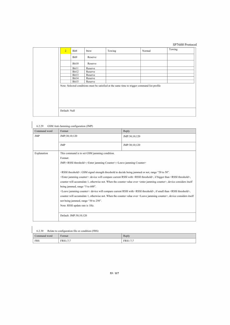
SP7600 Protocol
53 / 117
2 Bit8 btow Towing Normal Towing
Bit9 Reserve
Bit10 Reserve
Bit11 Reserve Bit12 Reserve Bit13 Reserve Bit14 Reserve Bit15 Reserve
Note: Selected conditions must be satisfied at the same time to trigger command list profile
Default: Null
6.2.29 GSM Anti-Jamming configuration (JMP)
Command word Format Reply
JMP JMP;30;10;120 JMP:30;10;120
JMP JMP:30;10;120
Explanation This command is to set GSM jamming condition.
Format:
JMP;<RSSI threshold>;<Enter jamming Counter>;<Leave jamming Counter>
<RSSI threshold>: GSM signal strength threshold to decide being jammed or not, range “20 to 50”.
<Enter jamming counter>: device will compare current RSSI with <RSSI threshold>, if bigger than <RSSI threshold>,
counter will accumulate 1, otherwise not. When the counter value over <enter jamming counter>, device considers itself
being jammed, range “5 to 600”.
<Leave jamming counter>: device will compare current RSSI with <RSSI threshold>, if small than <RSSI threshold>,
counter will accumulate 1, otherwise not. When the counter value over <Leave jamming counter>, device considers itself
not being jammed, range “30 to 250”.
Note: RSSI update rate is 1Hz.
Default: JMP:30;10;120
6.2.30 Relate to configuration file or condition (FRS)
Command word Format Reply
FRS FRS1;7;7 FRS1:7;7

SP7600 Protocol
54 / 117
Explanation This command is to set when certain condition is satisfied, device will automatically switch among configuration
profiles.
Format:
FRS<File ID>;<Condition mask>;<Condition status bit>
<File ID>: Range “1 to 5”.
<Condition mask>:
“0” Disable its corresponding condition.
“1” Enable its corresponding condition
<Condition status bit>:
“0” relate to value “0” of corresponding bit
“1” relate to value “1” of corresponding bit
Note: Condition only supports “or” gate.
e.g.:
FRL1;7;7
First “7” means Bit2 & Bit1 &Bit0 need to be related
Second “7” means any eventfrom “domestic roaming& backup battery abnormal& external power supply abnormal” is
satisfied, configuration file #1 will be executed.
Note: This feature is invalid at the first 30 seconds of tracker initialization
Default:
Condition status bit list
Byte Bit Definition Status 0 Status 1
1
Bit0 bExtPwr External power Normal Abnormal
Bit1 bInterBat Backup battery Normal Abnormal
Bit2 bRoaming Domestic roaming Normal Roaming
Bit3 bInterRoam International roaming Normal International
Bit4 bGeoFence Geo-fence Normal Geo-fence event
Bit5 bStop Parking Parking Quit parking
Bit6 bWorkStatus Private hour Normal Under private hour
Bit7 bAccOn ACC OFF ON
2
Bit8 bIn1 Digital input1 High or floating Low
Bit9 bIn2 Digital input2 High or floating Low
Bit10 bIn3 Digital input3 (AD3) Low High
Bit11 bTow Tow Normal Tow
Bit12 Reserved
Bit13 Reserved
Bit14 Reserved
Bit15 Reserved
6.2.31 Discard GPS position byHDOP (HOP)

SP7600 Protocol
55 / 117
Command word Format Reply
HOP HOP;0
HOP;1;3
HOP:0
HOP:1;3.00
HOP HOP:1;3.00
Explanation This command is to set HDOP threshold to discard inaccurate GPS positions.
Format:
HOP;<Para1>;<Para2>
<Para1>:
“0” disable HDOP filter
“1” enable HDOP filter, <Para2> is invalid in this case
<Para2>:
HDOP threshold, GPS position HDOP bigger than this value will be discarded, range 2 – 10.
Factory default: HDOP;1;3
6.2.32 Enable AT mode of GSM module (GAM)
Command word Format Reply
GAM GAM;1 GAM:1
GAM GAM:1
Explanation Format:
GAM;<mode>
<Mode>:
1: enable AT command mode, you can interact with GSM module with AT command.
0: disable AT command mode.
6.2.33 Send AT command to GSM module (GAT)
Command word Format Reply
GAT GAT;<AT command>
Explanation Format:
GAT;<AT command>
<AT command>;
Specify a certain AT command here, tracker will print log accordingly if command is correct, otherwise will return
“GSM is off”.
6.2.34 Generate and export current configuration file (CTF)
Command word Format Reply
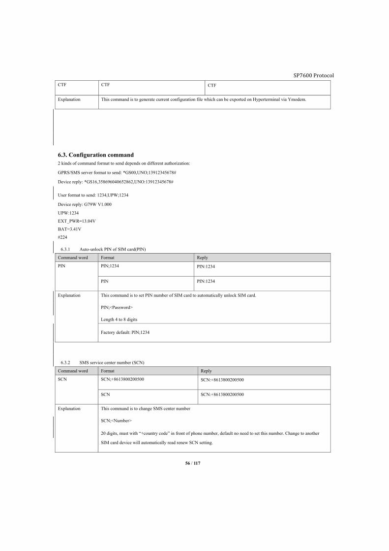
SP7600 Protocol
56 / 117
CTF CTF CTF
Explanation This command is to generate current configuration file which can be exported on Hyperterminal via Ymodem.
6.3. Configuration command 2 kinds of command format to send depends on different authorization:
GPRS/SMS server format to send: *GS00,UNO;13912345678#
Device reply: *GS16,358696040652862,UNO:13912345678#
User format to send: 1234,UPW;1234
Device reply: G79W V1.000
UPW:1234
EXT_PWR=13.04V
BAT=3.41V
#224
6.3.1 Auto-unlock PIN of SIM card(PIN)
Command word Format Reply
PIN PIN;1234 PIN:1234
PIN PIN:1234
Explanation This command is to set PIN number of SIM card to automatically unlock SIM card.
PIN;<Password>
Length 4 to 8 digits
Factory default: PIN;1234
6.3.2 SMS service center number (SCN)
Command word Format Reply
SCN SCN;+8613800200500 SCN:+8613800200500
SCN SCN:+8613800200500
Explanation This command is to change SMS center number
SCN;<Number>
20 digits, must with “+country code” in front of phone number, default no need to set this number. Change to another
SIM card device will automatically read renew SCN setting.

SP7600 Protocol
57 / 117
Note: “+” is a must for country code.
Default: SCN
6.3.3 Set APN (APN)
Command word Format Reply
APN APN;cmnet;usr;pw APN;cmnet;usr;pw
APN APN:cmnet
Explanation This command is a must for GPRS connectivity.
<APN>: 1 to 64 characters
<user name>: 0 to 32 characters
<password>: 0 to 32 characters
If there is not username and password for APN, command could be:
APN;<APN>
Note: Device already save some APN information, it the SIM card is recognized it will fulfill APN automatically
Default: Null
6.3.4 Set GPRS main server (SVR)
Command word Format Reply
SVR Set as TCP socket:
SVR;114.142.154.28;3032;;0;0
or
SVR;www.anytracking.net;3032;;0;0
Set as UDP socket
SVR;114.142.154.28;;3032;1;1
or
SVR;www.anytracking.net;;3032;1;1
Delete main server:
SVR;
Set as TCP socket:
SVR:114.142.154.28;3032;;0;0
or
SVR:www.anytracking.net;3032;;0;0
Set as UDP socket
SVR:114.142.154.28;;3032;1;1
or
SVR:www.anytracking.net;;3032;1;1
Reply:
SVR:
SVR SVR:114.142.154.28;3032;;0;0
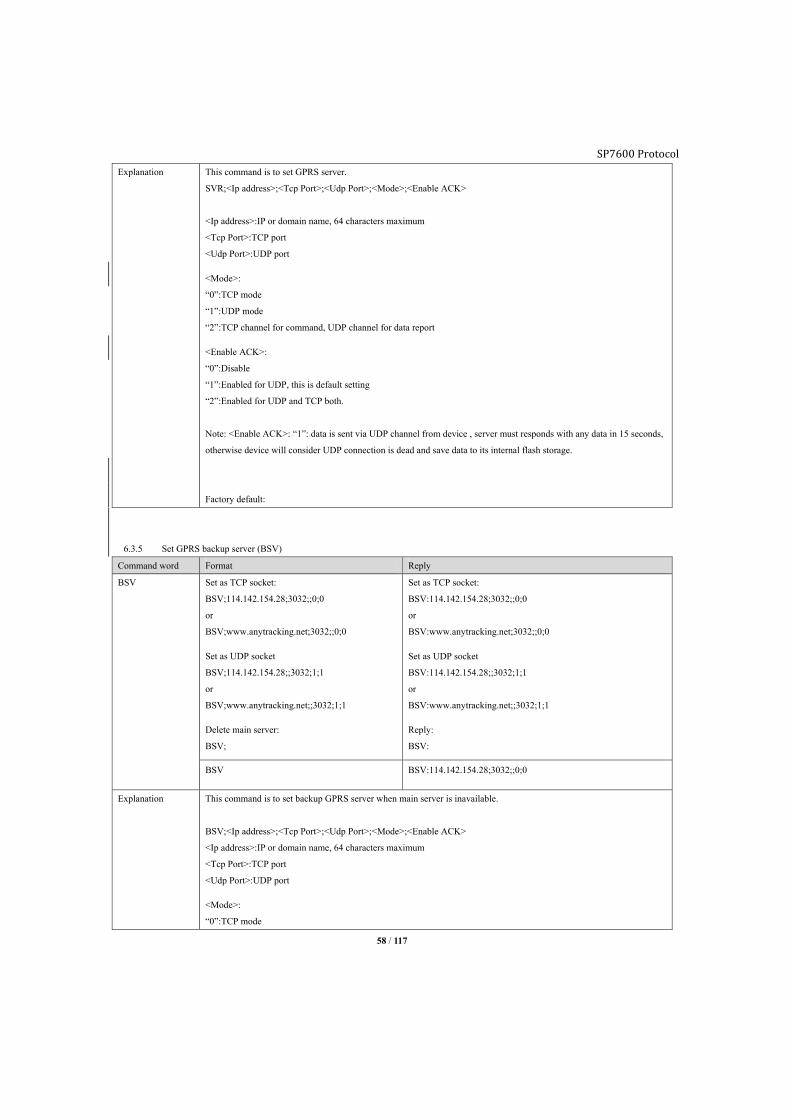
SP7600 Protocol
58 / 117
Explanation This command is to set GPRS server.
SVR;<Ip address>;<Tcp Port>;<Udp Port>;<Mode>;<Enable ACK>
<Ip address>:IP or domain name, 64 characters maximum
<Tcp Port>:TCP port
<Udp Port>:UDP port
<Mode>:
“0”:TCP mode
“1”:UDP mode
“2”:TCP channel for command, UDP channel for data report
<Enable ACK>:
“0”:Disable
“1”:Enabled for UDP, this is default setting
“2”:Enabled for UDP and TCP both.
Note: <Enable ACK>: “1”: data is sent via UDP channel from device , server must responds with any data in 15 seconds,
otherwise device will consider UDP connection is dead and save data to its internal flash storage.
Factory default:
6.3.5 Set GPRS backup server (BSV)
Command word Format Reply
BSV Set as TCP socket:
BSV;114.142.154.28;3032;;0;0
or
BSV;www.anytracking.net;3032;;0;0
Set as UDP socket
BSV;114.142.154.28;;3032;1;1
or
BSV;www.anytracking.net;;3032;1;1
Delete main server:
BSV;
Set as TCP socket:
BSV:114.142.154.28;3032;;0;0
or
BSV:www.anytracking.net;3032;;0;0
Set as UDP socket
BSV:114.142.154.28;;3032;1;1
or
BSV:www.anytracking.net;;3032;1;1
Reply:
BSV:
BSV BSV:114.142.154.28;3032;;0;0
Explanation This command is to set backup GPRS server when main server is inavailable.
BSV;<Ip address>;<Tcp Port>;<Udp Port>;<Mode>;<Enable ACK>
<Ip address>:IP or domain name, 64 characters maximum
<Tcp Port>:TCP port
<Udp Port>:UDP port
<Mode>:
“0”:TCP mode

SP7600 Protocol
59 / 117
“1”:UDP mode
“2”:TCP channel for command, UDP channel for data report
<Enable ACK>:
“0”:Disable
“1”:Enabled for UDP, this is default setting
“2”:Enabled for UDP and TCP both.
Note: <Enable ACK>, data is sent via UDP channel from device , server must respond with any data in 15 seconds,
otherwise device will consider UDP connection is dead and save data to its flash storage.
Factory default:
6.3.6 Records batch process (BDU)
Command word Format Reply
BDU BDU;1
BDU1;20
BDU:1
BDU1:20
BDU
BDU1
BDU:1
BDU1:20
Explanation This command is to pack multiple position as a packet and report to server to save GPRS data flow, but it will affect the
real time report to server. Once the pre set value is met (regular packet/serial port packet) device will report immediately,
and reset the counter.
BDU;<Parameter>
This is to set regular packet threshold
BDU1;<Parameter>
This is to set serial port packet threhold
<Parameter>: range is “1 to 255”.
“1” means each position packet will be reported to server immediately.
e.g.:
BDU:10 means device waits for 10 regular position packets to pack as 1 packet to report
BDU1;30 means device waits for 30 packets from serial link to pack as 1 packet to report
Note:
1, Either BDU or BDU1 is met, device will report instantly.
2, Event report always immediately
Default:
BDU;1

SP7600 Protocol
60 / 117
BDU1;1
6.3.7 GPRS server report interval mode (SVP)
Command word Format Reply
SVP SVP;1;15S;G;B SVP:1;15S;G;B
SVP;1 SVP:1;15S;G;B
Explanation This command is set report interval of mode0 (static) and mode1 (dynamic)
SVP;<Mode>;<Interval>;<Report mode>;<Data format>
<Mode>:
“0”: Report mode0
“1”: Report mode1, valid only when command DNU is enabled.
<Interval>: range is “5 to 900 seconds”, “15 to 59 minutes”, “1to 720 hours”
<Report mode>:
“O”: Disable
“G”: GPS information prior
“A”: GPS and GSM information
<Data format>:
“O”: Device will not generate data (record)
“B”: HEX
“T”: ASCII
Default:
SVP:0;30S;G;B,
SVP:1;600S;G;B
6.3.8 SMS server report interval mode (SSP)
Command word Format Reply
SSP SSP;1;12H;G;T SSP:1;12H;G;T
SSP SSP:1;12H;G;T
Explanation This command is to set mode0 and mode1 report interval for SMS server
SSP;<Mode>;<Interval>;<Report mode>;<Data format>
<Mode>:
“0”: Report mode0
“1”: Report mode1, valid only when command DNU is enabled.
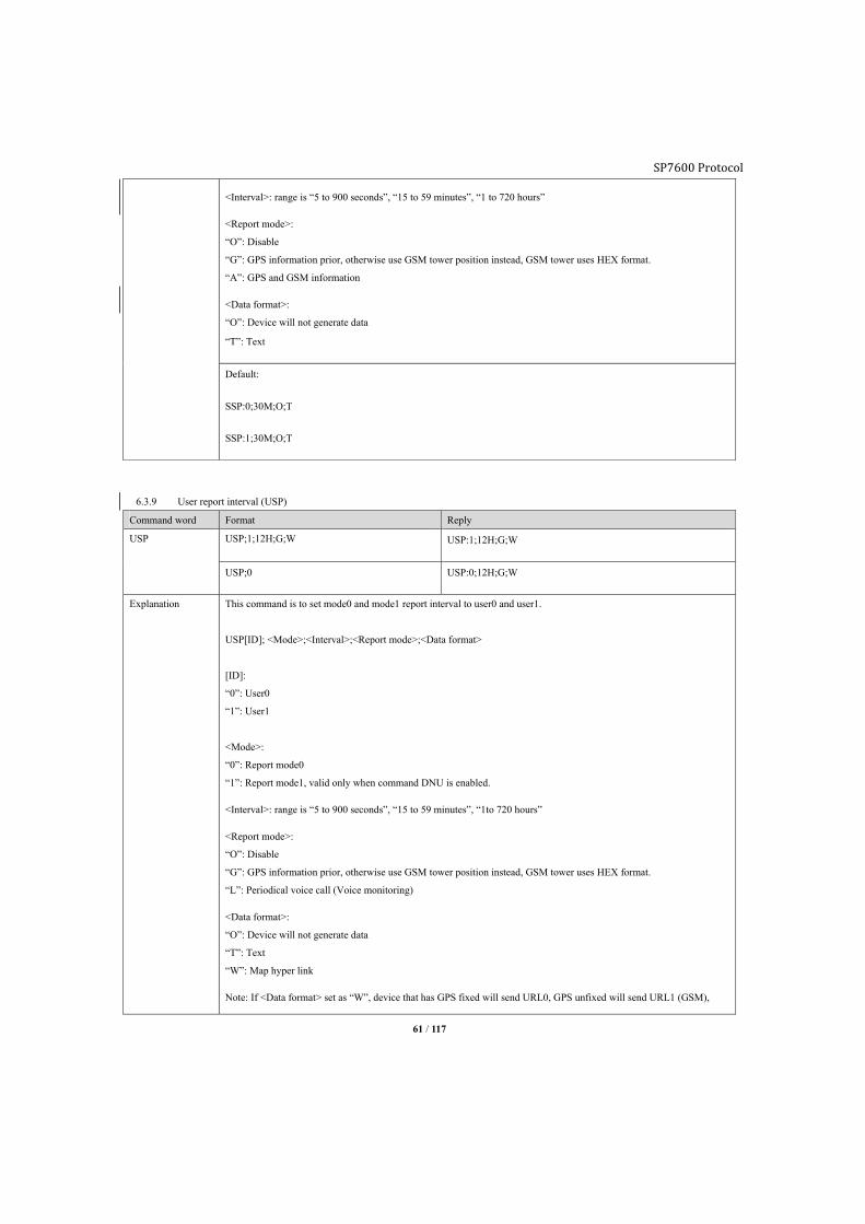
SP7600 Protocol
61 / 117
<Interval>: range is “5 to 900 seconds”, “15 to 59 minutes”, “1 to 720 hours”
<Report mode>:
“O”: Disable
“G”: GPS information prior, otherwise use GSM tower position instead, GSM tower uses HEX format.
“A”: GPS and GSM information
<Data format>:
“O”: Device will not generate data
“T”: Text
Default:
SSP:0;30M;O;T
SSP:1;30M;O;T
6.3.9 User report interval (USP)
Command word Format Reply
USP USP;1;12H;G;W USP:1;12H;G;W
USP;0 USP:0;12H;G;W
Explanation This command is to set mode0 and mode1 report interval to user0 and user1.
USP[ID]; <Mode>;<Interval>;<Report mode>;<Data format>
[ID]:
“0”: User0
“1”: User1
<Mode>:
“0”: Report mode0
“1”: Report mode1, valid only when command DNU is enabled.
<Interval>: range is “5 to 900 seconds”, “15 to 59 minutes”, “1to 720 hours”
<Report mode>:
“O”: Disable
“G”: GPS information prior, otherwise use GSM tower position instead, GSM tower uses HEX format.
“L”: Periodical voice call (Voice monitoring)
<Data format>:
“O”: Device will not generate data
“T”: Text
“W”: Map hyper link
Note: If <Data format> set as “W”, device that has GPS fixed will send URL0, GPS unfixed will send URL1 (GSM),
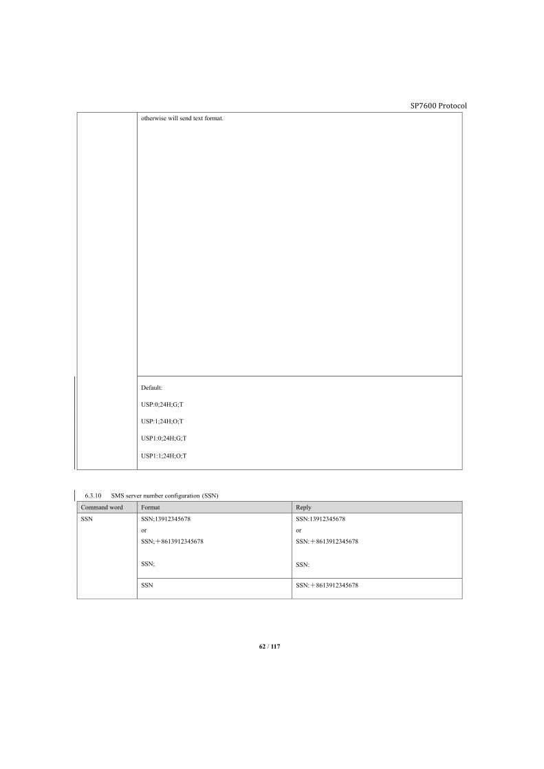
SP7600 Protocol
62 / 117
otherwise will send text format.
Default:
USP:0;24H;G;T
USP:1;24H;O;T
USP1:0;24H;G;T
USP1:1;24H;O;T
6.3.10 SMS server number configuration (SSN)
Command word Format Reply
SSN SSN;13912345678
or
SSN;+8613912345678
SSN;
SSN:13912345678
or
SSN:+8613912345678
SSN:
SSN SSN:+8613912345678
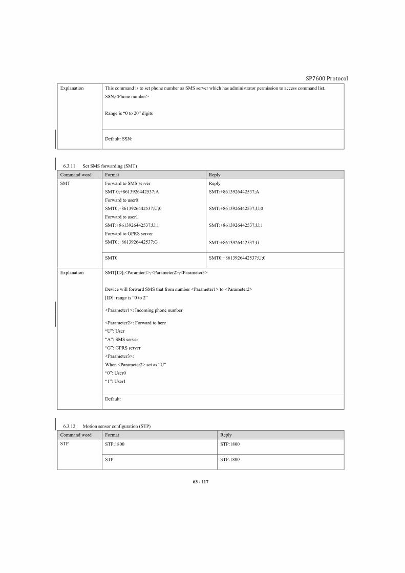
SP7600 Protocol
63 / 117
Explanation This command is to set phone number as SMS server which has administrator permission to access command list.
SSN;<Phone number>
Range is “0 to 20” digits
Default: SSN:
6.3.11 Set SMS forwarding (SMT)
Command word Format Reply
SMT Forward to SMS server
SMT 0;+8613926442537;A
Forward to user0
SMT0;+8613926442537;U;0
Forward to user1
SMT:+8613926442537;U;1
Forward to GPRS server
SMT0;+8613926442537;G
Reply
SMT:+8613926442537;A
SMT:+8613926442537;U;0
SMT:+8613926442537;U;1
SMT:+8613926442537;G
SMT0 SMT0:+8613926442537;U;0
Explanation SMT[ID];<Paramter1>;<Parameter2>;<Parameter3>
Device will forward SMS that from number <Parameter1> to <Parameter2>
[ID]: range is “0 to 2”
<Parameter1>: Incoming phone number
<Parameter2>: Forward to here
“U”: User
“A”: SMS server
“G”: GPRS server
<Parameter3>:
When <Parameter2> set as “U”
“0”: User0
“1”: User1
Default:
6.3.12 Motion sensor configuration (STP)
Command word Format Reply
STP STP;1800 STP:1800
STP STP:1800
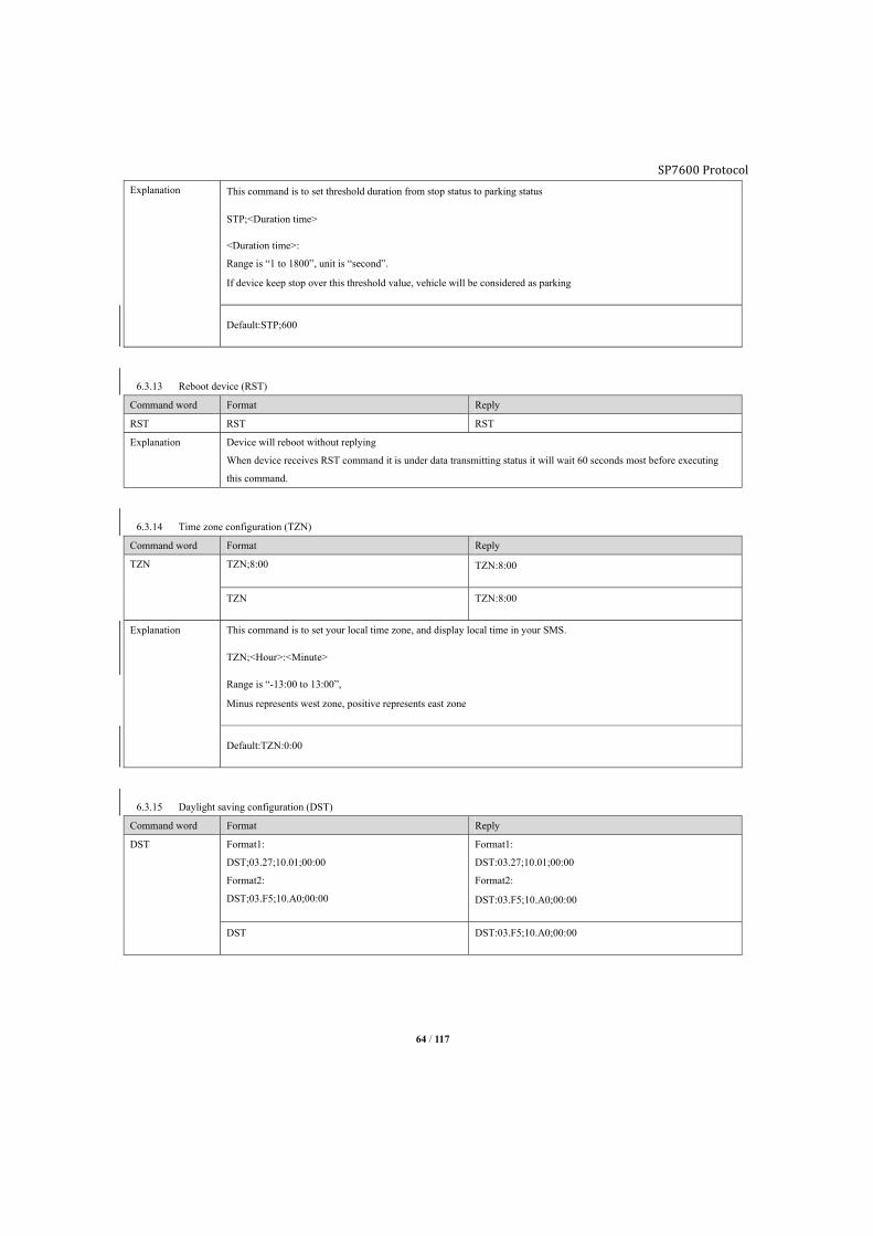
SP7600 Protocol
64 / 117
Explanation This command is to set threshold duration from stop status to parking status
STP;<Duration time>
<Duration time>:
Range is “1 to 1800”, unit is “second”.
If device keep stop over this threshold value, vehicle will be considered as parking
Default:STP;600
6.3.13 Reboot device (RST)
Command word Format Reply
RST RST RST
Explanation Device will reboot without replying
When device receives RST command it is under data transmitting status it will wait 60 seconds most before executing
this command.
6.3.14 Time zone configuration (TZN)
Command word Format Reply
TZN TZN;8:00 TZN:8:00
TZN TZN:8:00
Explanation This command is to set your local time zone, and display local time in your SMS.
TZN;<Hour>:<Minute>
Range is “-13:00 to 13:00”,
Minus represents west zone, positive represents east zone
Default:TZN:0:00
6.3.15 Daylight saving configuration (DST)
Command word Format Reply
DST Format1:
DST;03.27;10.01;00:00
Format2:
DST;03.F5;10.A0;00:00
Format1:
DST:03.27;10.01;00:00
Format2:
DST:03.F5;10.A0;00:00
DST DST:03.F5;10.A0;00:00
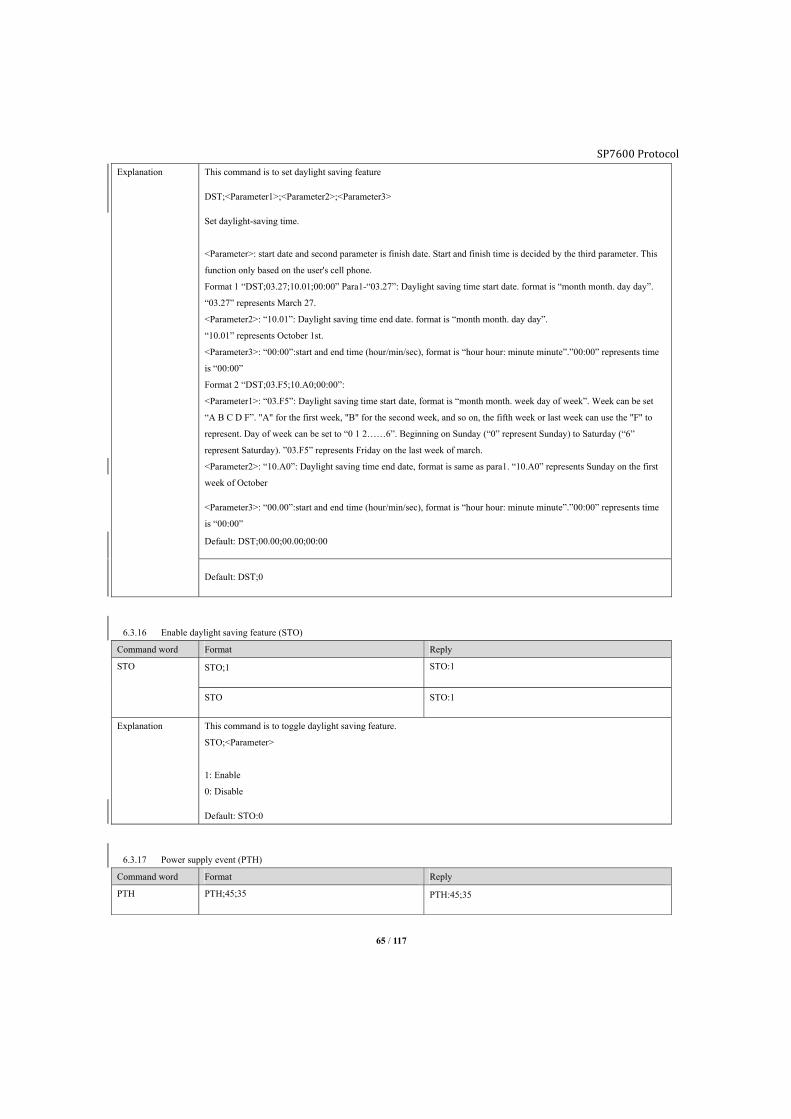
SP7600 Protocol
65 / 117
Explanation This command is to set daylight saving feature
DST;<Parameter1>;<Parameter2>;<Parameter3>
Set daylight-saving time.
<Parameter>: start date and second parameter is finish date. Start and finish time is decided by the third parameter. This
function only based on the user's cell phone.
Format 1 “DST;03.27;10.01;00:00” Para1-“03.27”: Daylight saving time start date. format is “month month. day day”.
“03.27” represents March 27.
<Parameter2>: “10.01”: Daylight saving time end date. format is “month month. day day”.
“10.01” represents October 1st.
<Parameter3>: “00:00”:start and end time (hour/min/sec), format is “hour hour: minute minute”.”00:00” represents time
is “00:00”
Format 2 “DST;03.F5;10.A0;00:00”:
<Parameter1>: “03.F5”: Daylight saving time start date, format is “month month. week day of week”. Week can be set
“A B C D F”. "A" for the first week, "B" for the second week, and so on, the fifth week or last week can use the "F" to
represent. Day of week can be set to “0 1 2……6”. Beginning on Sunday (“0” represent Sunday) to Saturday (“6”
represent Saturday). ”03.F5” represents Friday on the last week of march.
<Parameter2>: “10.A0”: Daylight saving time end date, format is same as para1. “10.A0” represents Sunday on the first
week of October
<Parameter3>: “00.00”:start and end time (hour/min/sec), format is “hour hour: minute minute”.”00:00” represents time
is “00:00”
Default: DST;00.00;00.00;00:00
Default: DST;0
6.3.16 Enable daylight saving feature (STO)
Command word Format Reply
STO STO;1 STO:1
STO STO:1
Explanation This command is to toggle daylight saving feature.
STO;<Parameter>
1: Enable
0: Disable
Default: STO:0
6.3.17 Power supply event (PTH)
Command word Format Reply
PTH PTH;45;35 PTH:45;35
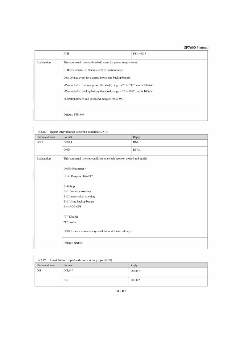
SP7600 Protocol
66 / 117
PTH PTH:45;35
Explanation This command is to set threshold value for power supply event.
PTH;<Parameter1>;<Parameter2><Duration time>
Low voltage event for external power and backup battery.
<Parameter1>: External power threshold, range is “0 to 999”, unit is 100mV.
<Parameter2>: Backup battery threshold, range is “0 to 999”, unit is 100mV.
<Duration time>: unit is second, range is “0 to 255”
Default: PTH:0;0
6.3.18 Report interval mode switching condition (DNU)
Command word Format Reply
DNU DNU;1 DNU:1
DNU DNU:1
Explanation This command is to set conditions to switch between mode0 and mode1
DNU;<Parameter>
HEX, Range is “0 to FF”
Bit0:Stop
Bit1:Domestic roaming
Bit2:Internatoinal roaming
Bit3:Using backup battery
Bit4:ACC OFF
”0”: Disable
“1”:Enable
DNU;0 means device always stick to mode0 interval only.
Default: DNU;0
6.3.19 Fixed distance report and corner turning report (DIS)
Command word Format Reply
DIS DIS;0;7 DIS:0;7
DIS DIS:0;7

SP7600 Protocol
67 / 117
Explanation This command is to set threshold value for cornering and distance report
DIS;<Distance><Angle>
Device will report once fixed distance or cornering angle is satisfied
<Distance>: range is “0 to 255”, unit is “0.1km”.
<Angle>: range is “3 to 20”, unit is “degree”
Default:DIS;0;7
6.3.20 Voice functionality configuration (VOE)
Command word Format Reply
VOE VOE;1;1
VOE
VOE:1;1
VOE:1;1
Explanation This command is to toggle voice feature
VOE;<Voice call mode>;<SOS mode>;<SOS I/O port ID>
<Voice call mode>:
“0”: Disable call in and out
“1”: Enable call in and out
<SOS mode>:
“0”: Disable voice SOS
“1”: Enable voice SOS (conversation mode)
“2”: Enable voice SOS (Listening only)
<SOS I/O input ID>:
Assign SOS input channel, range is “0 to 1”.
Note1:
If <Voice call mode> set as “0”, only admin/user PRQ functionality available.
Note2:
If <Voice call mode> set as “0”,
>Incoming phone number in white list,
If it is PRQ authorization, device will hang up. If it is monitoring authorization, device will pick up. If its hot line
authorization, device will pick up.
>Incoming phone number is admin (SMS server), device will pick up in 15 seconds.
Default:VOE:1;0;
6.3.21 Phone number white list (PWL)
Command word Format Reply
PWL PWL;S;1;14714821165
PWL;R;1
PWL:S;1;14714821165
PWL;R;1;14714821165
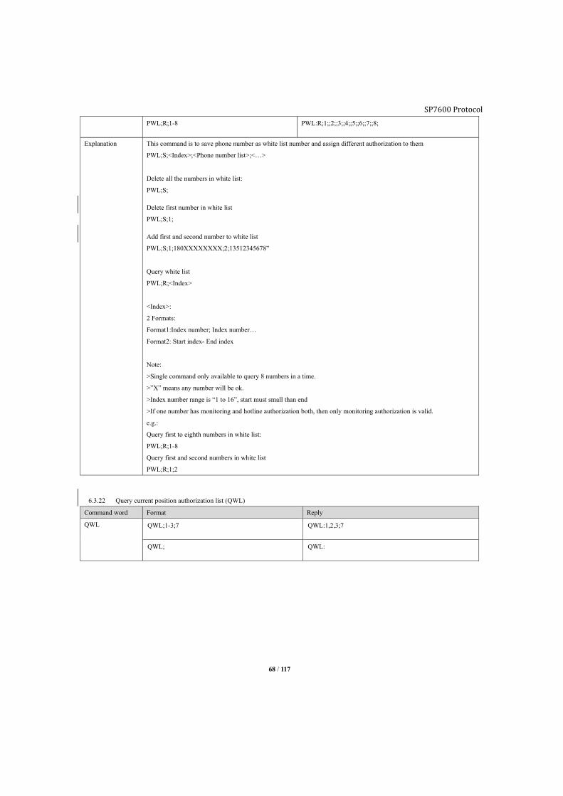
SP7600 Protocol
68 / 117
PWL;R;1-8 PWL:R;1;;2;;3;;4;;5;;6;;7;;8;
Explanation This command is to save phone number as white list number and assign different authorization to them
PWL;S;<Index>;<Phone number list>;<…>
Delete all the numbers in white list:
PWL;S;
Delete first number in white list
PWL;S;1;
Add first and second number to white list
PWL;S;1;180XXXXXXXX;2;13512345678”
Query white list
PWL;R;<Index>
<Index>:
2 Formats:
Format1:Index number; Index number…
Format2: Start index- End index
Note:
>Single command only available to query 8 numbers in a time.
>”X” means any number will be ok.
>Index number range is “1 to 16”, start must small than end
>If one number has monitoring and hotline authorization both, then only monitoring authorization is valid.
e.g.:
Query first to eighth numbers in white list:
PWL;R;1-8
Query first and second numbers in white list
PWL;R;1;2
6.3.22 Query current position authorization list (QWL)
Command word Format Reply
QWL QWL;1-3;7 QWL:1,2,3;7
QWL; QWL:

SP7600 Protocol
69 / 117
Explanation This is to enable phone number from white list for current position query purpose, device will reject the call and reply a
SMS with current position.
QWL;<Index>
Explanation:
<Index>: Assign numbers to have “Query current position authorization” from white list.
e.g.: Assign number 1,2,3,7 from white list
QWL;1-3;7
or
QWL;1;2;3;7
Default: QWL
6.3.23 Voice monitoring authorization list (MWL)
Command word Format Reply
MWL MWL;1-3;7 MWL:1;2;3;7
Explanation This command is to enable phone number from white list to have voice monitoring permission, device will pick up the
call and enable its microphone for voice monitor purpose.
MWL; <Index>
Explanation:
<Index>: Assign numbers to have “Voice monitoring authorization” from white list.
e.g.: Assign number 1,2,3,7 from white list
MWL;1,2,3;7
or
MWL;1,2,3;7
Default: MWL;
6.3.24 Hot line authorization (HWL)
Command word Format Reply
HWL HWL;1-3;7 HWL:1,2,3;7
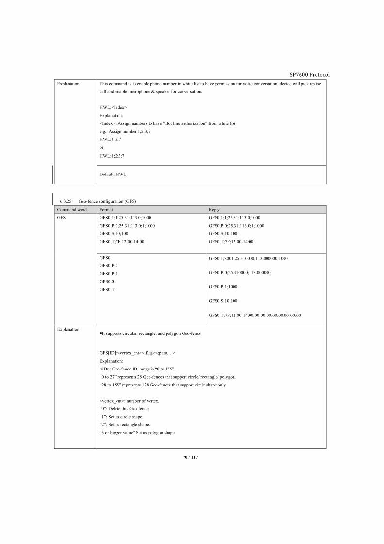
SP7600 Protocol
70 / 117
Explanation This command is to enable phone number in white list to have permission for voice conversation, device will pick up the
call and enable microphone & speaker for conversation.
HWL;<Index>
Explanation:
<Index>: Assign numbers to have “Hot line authorization” from white list
e.g.: Assign number 1,2,3,7
HWL;1-3;7
or
HWL;1;2;3;7
Default: HWL
6.3.25 Geo-fence configuration (GFS)
Command word Format Reply
GFS GFS0;1;1;25.31;113.0;1000
GFS0;P;0;25.31;113.0;1;1000
GFS0;S;10;100
GFS0;T;7F;12:00-14:00
GFS0;1;1;25.31;113.0;1000
GFS0;P;0;25.31;113.0;1;1000
GFS0;S;10;100
GFS0;T;7F;12:00-14:00
GFS0
GFS0;P;0
GFS0;P;1
GFS0;S
GFS0;T
GFS0:1;8001;25.310000;113.000000;1000
GFS0:P;0;25.310000;113.000000
GFS0:P;1;1000
GFS0:S;10;100
GFS0:T;7F;12:00-14:00;00:00-00:00;00:00-00:00
Explanation ■It supports circular, rectangle, and polygon Geo-fence
GFS[ID];<vertex_cnt><;flag><;para….>
Explanation:
<ID>: Geo-fence ID, range is “0 to 155”.
“0 to 27” represents 28 Geo-fences that support circle/ rectangle/ polygon.
“28 to 155” represents 128 Geo-fences that support circle shape only
<vertex_cnt>: number of vertex,
”0”: Delete this Geo-fence
“1”: Set as circle shape.
“2”: Set as rectangle shape.
“3 or bigger value” Set as polygon shape

SP7600 Protocol
71 / 117
Flag to configure Geo-fence attribution:
Bit0 Enable entering detection
Bit1 Enable leaving detection
Bit2 Enable inside speed range detection
Bit3 Enable outside speed range detection
Bit4 Enable valid time period
Bit5 Reserved
Bit6 Reserved
Bit7 Reserved
Bit8 Reserved
Bit9 Reserved
Bit10 Reserved
Bit11 Reserved
Bit12 Reserved
Bit13 Time validation flag
Bit14 Speed validation flag
Bit15 Geo-fence validation flag
“Bit0 to Bit1”: one of them must be “1”. System will force “Bit0” as “1” when set “Bit0 and Bit1” as “00”.
“Bit3 to Bit2”:
“00”: Represents detecting device in or out of Geo-fence, not refer speed.
“01”: Represents only inside the preset speed range, device to detect in or out of Geo-fence.
“10”: Represents only outside the preset speed range, device to detect in or out of Geo-fence.
“11”: System will treat it as “00”.
“Bit4”:
“0”: Disable valid time period
“1” Enable only in time period, device to detect in or out of Geo-fence
Note: Only if time and speed condition being satisfied, device will report Geo-fence event, otherwise device just detect
current status.
“Bit5 to Bit12”:
Reserved.
“Bit13”: Time validation flag, “1” such condition is enabled.
“Bit14”: Speed validation flag, “1” such condition is enabled.
“Bit15”: Geo-fence validation flag, “1” such condition is enabled.
<Para…>” Parameter of circle or rectangle Geo-fence, if <vertex_cnt> value is “1” or “2”, Geo-fence has parameter to
set:
For circle Geo-fence, <Para…> is <center latitude, center longitude, radius>.
For rectangle Geo-fence, <Para…> is <vertex1 latitude, vertex1 longitude, vertex2 latitude, vertex2 longitude…>
Query Geo-fence configuration:
GFS[ID]

SP7600 Protocol
72 / 117
Set Geo-fence
GFS[ID];P;para_ID;para_val<;para_ID;para_val>…
Explanation:
para_ID: Geo-fence ID
For circle, “0” means center latitude and longitude, “1” means radius.
For rectangle, “0” means vertex1 latitude and longitude, “1” means vertex2 latitude and longitude.
Polygon: “0 to 31” means latitude and longitude of each vertex.
para_val:
If it means GPS coordinate, format is latitude; longitude, south latitude and west longitude will be minus value.
If it means radius, format is radius, unit is meter.
Latitude range is less than +-90, longitude not more than +-180.
Radius is more than 200 meters, integer value.
To distinguish para_ID and para_val, para_ID length not more than 2, para_val more than 3.
Query Geo-fence configuration
GFS[ID];P;para_ID<;para_ID>…
Set speed parameter:
GFS[ID];S<;min_speed><;max_speed>
GFS[ID];S is to query
GFS[ID];S; is to delete
<min_speed>: Lower limit of speed range, “0” means disabled.
<max_speed>-: Upper limit of speed range, “0” means disabled.
If speed parameter is valid, “Bit14” of Geo-fence attribution will be “1”.
Null speed parameter, or upper limit and lower limit both “0”, need to set “Bit14” of Geo-fence attribution as “0”.
GFS[ID];T<;workday_mask><;time_period1><; time_period2><; time_period3>
Explanation:
<workday_mask>: Day of work mask.
Bit0 Sunday
Bit1 Monday
Bit2 Tuesday
Bit3 Wednesday
Bit4 Thursday
Bit5 Friday
Bit6 Saturday
Bit7 Reserved
0: Disable this day of week
1: Enable this day of week

SP7600 Protocol
73 / 117
<time_period1>: First period, format is “hh:mm-hh:mm”
<time_period2>: Second period, format is “hh:mm-hh:mm”
<time_period3>: Third period, format is “hh:mm-hh:mm”
Note: End time must be ahead start time
6.3.26 Enable Geo-fence (GOF)
Command word Format Reply
GOF GOF;108000001 GOF:108000001
GOF GOF:108000001
Explanation This command is to toggle specify geo fence detection.
GOF<;enable_mask>
<enable_mask>:
HEX, length is 20 bytes.
28 Geo-fences (Round/Rectangular/Polygon),corresponding with bit0 to bit27,
128 Geo-fences, corresponding with bit28 to bit155,
0:Disable this Geo-fence
1:Enable this Geo-fence
e.g. enable Geo fence #0,#27,#28
GOF;108000001
6.3.27 Enable driving behavior detection (BMO)
Command word Format Reply
BMO BMO;1;1;1;1 BMO:1;1;1
BMO BMO:1;1;1

SP7600 Protocol
74 / 117
Explanation This command is to toggle harsh event, motion event detection.
BMO; <moving_enable>;<harsh_braker_enable>;<harsh_accel_enable>;<harsh_corner_enable>
<moving_enable>
“0”: Disable moving detection.
“1”: Enable moving detection.
<harsh_braker_enable>
“0”: Disable harsh brake detection.
“1”: Enable harsh brake detection.
<harsh_accel_enable>
“0”: Disable harsh accelerate detection.
“1”: Enable harsh accelerate detection.
<harsh_corner_enable.
“0”: Disable harsh cornering detection.
“1”: Enable harsh cornering detection.
Default:BMO;1;1;1;1
6.3.28 Enable accident detection (AMO)
Command word Format Reply
AMO AMO;1;1 AMO:1;1
AMO AMO:1;1
Explanation This command is to toggle accident & turn over event.
AMO; <crash_enable>;<turn_over_enable>
<crash_ enable>
“0”: Disable rear collision detection.
“1”: Enable rear collision detection.
Note: Sensor will judge front/rear by itself.
<turn_over_enable>
“0”: Disable turn over detection.
“1”: Enable turn over detection.
Default: AMO;1;1
6.3.29 Enable odometer counter (MGE)
Command word Format Reply
MGE MGE;1 MGE:1
MGE MGE:1
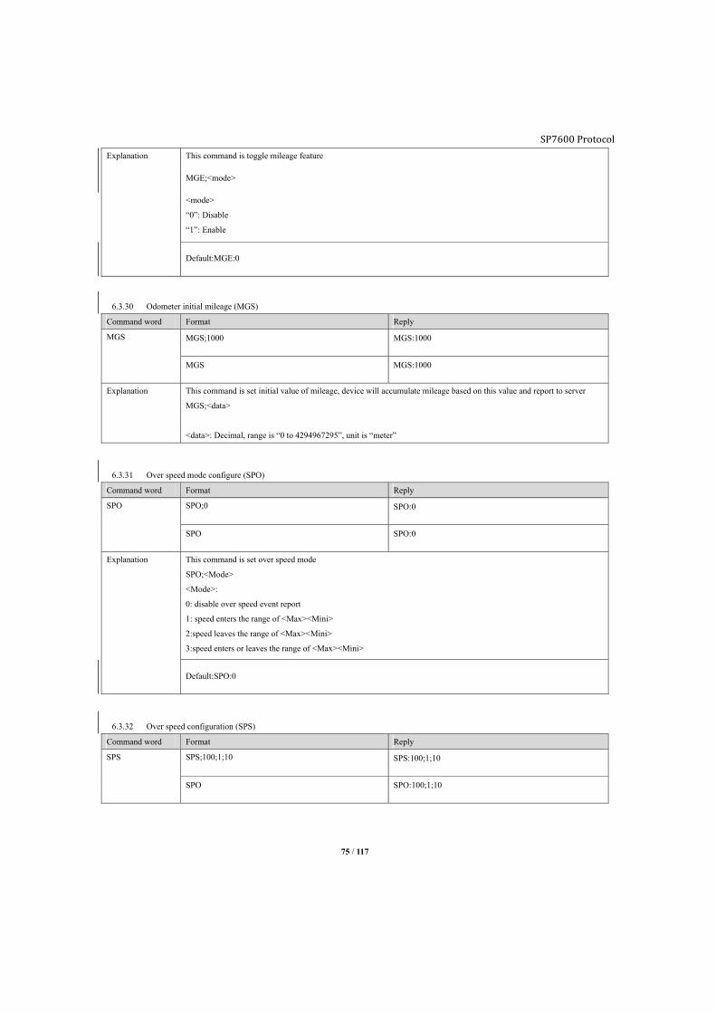
SP7600 Protocol
75 / 117
Explanation This command is toggle mileage feature
MGE;<mode>
<mode>
“0”: Disable
“1”: Enable
Default:MGE:0
6.3.30 Odometer initial mileage (MGS)
Command word Format Reply
MGS MGS;1000 MGS:1000
MGS MGS:1000
Explanation This command is set initial value of mileage, device will accumulate mileage based on this value and report to server
MGS;<data>
<data>: Decimal, range is “0 to 4294967295”, unit is “meter”
6.3.31 Over speed mode configure (SPO)
Command word Format Reply
SPO SPO;0 SPO:0
SPO SPO:0
Explanation This command is set over speed mode
SPO;<Mode>
<Mode>:
0: disable over speed event report
1: speed enters the range of <Max><Mini>
2:speed leaves the range of <Max><Mini>
3:speed enters or leaves the range of <Max><Mini>
Default:SPO:0
6.3.32 Over speed configuration (SPS)
Command word Format Reply
SPS SPS;100;1;10 SPS:100;1;10
SPO SPO:100;1;10
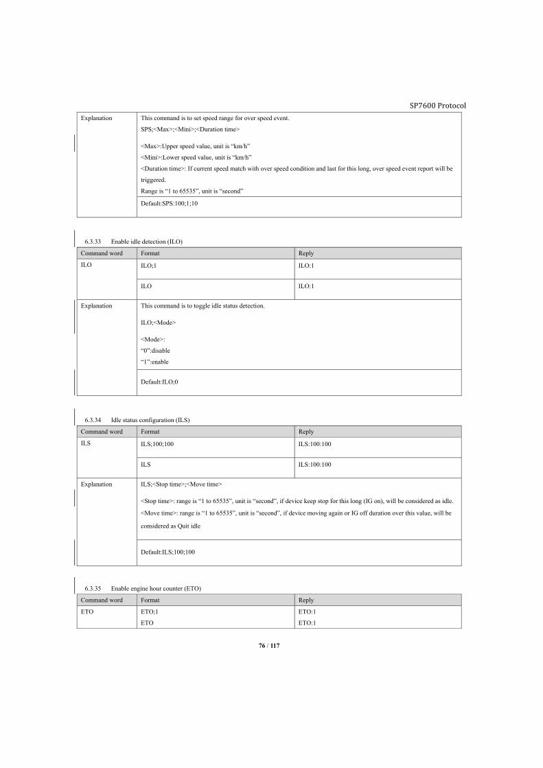
SP7600 Protocol
76 / 117
Explanation This command is to set speed range for over speed event.
SPS;<Max>;<Mini>;<Duration time>
<Max>:Upper speed value, unit is “km/h”
<Mini>:Lower speed value, unit is “km/h”
<Duration time>: If current speed match with over speed condition and last for this long, over speed event report will be
triggered.
Range is “1 to 65535”, unit is “second”
Default:SPS:100;1;10
6.3.33 Enable idle detection (ILO)
Command word Format Reply
ILO ILO;1 ILO:1
ILO ILO:1
Explanation This command is to toggle idle status detection.
ILO;<Mode>
<Mode>:
“0”:disable
“1”:enable
Default:ILO;0
6.3.34 Idle status configuration (ILS)
Command word Format Reply
ILS ILS;100;100 ILS:100:100
ILS ILS:100:100
Explanation ILS;<Stop time>;<Move time>
<Stop time>: range is “1 to 65535”, unit is “second”, if device keep stop for this long (IG on), will be considered as idle.
<Move time>: range is “1 to 65535”, unit is “second”, if device moving again or IG off duration over this value, will be
considered as Quit idle
Default:ILS;100;100
6.3.35 Enable engine hour counter (ETO)
Command word Format Reply
ETO ETO;1
ETO
ETO:1
ETO:1

SP7600 Protocol
77 / 117
Explanation This command is to toggle engine hour counter
ETO;<Mode>
<Mode>:
“0”: Disable
“1”: Enable
Default: ETO;0
6.3.36 Set engine hour counter (ETS)
Command word Format Reply
ETS ETS;88888:0:0;1 ETS;88888:0:0;1
ETS ETS:88888:0:0;1
Explanation This command is to set initial engine hour, device will accumulate based on this value.
ETS;<Hour>;<Minute>;<Second>
<Hour>: 5 digits maximum
<Minute>: 2 digits maximum
<Second>: 2 digit maximum
Range is “0:0:0 to 99999:0:0”, the <Engine hour counter> in IG ON report will accumulate base on this value.
<I/O port>
To assign which port as engine status input port.
“0”: AD1, only valid when “AD1/IN3” set as digital
“1”: AD2, only valid when “AD2/IN4” set as digital
below conditions must be satisfied:
>AIM set as digital
>DIM mode0
6.3.37 Health check report (HTM)
Command word Format Reply
HTM HTM;1;1 HTM:1;1
HTM HTM:1;1
Explanation This command is to set health check packet report interval to GPRS server.
HTM;<Mode>
HTM;<Mode>;<Time>
Query health check report:
Send (GPRS/SMS server):
*GS00,HTM;0#
Reply:
*GS06,356496042331108,HTM:0#
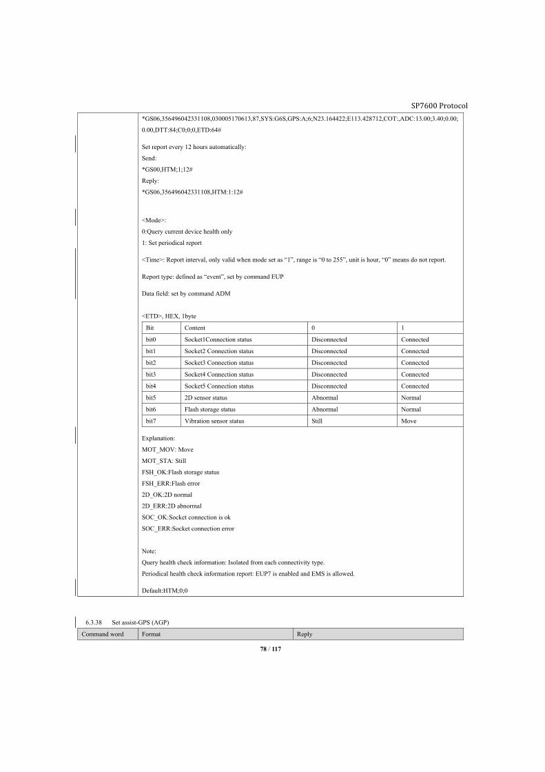
SP7600 Protocol
78 / 117
*GS06,356496042331108,030005170613,87,SYS:G6S,GPS:A;6;N23.164422;E113.428712,COT:,ADC:13.00;3.40;0.00;
0.00,DTT:84;C0;0;0,ETD:64#
Set report every 12 hours automatically:
Send:
*GS00,HTM;1;12#
Reply:
*GS06,356496042331108,HTM:1:12#
<Mode>:
0:Query current device health only
1: Set periodical report
<Time>: Report interval, only valid when mode set as “1”, range is “0 to 255”, unit is hour, “0” means do not report.
Report type: defined as “event”, set by command EUP
Data field: set by command ADM
<ETD>, HEX, 1byte
Bit Content 0 1
bit0 Socket1Connection status Disconnected Connected
bit1 Socket2 Connection status Disconnected Connected
bit2 Socket3 Connection status Disconnected Connected
bit3 Socket4 Connection status Disconnected Connected
bit4 Socket5 Connection status Disconnected Connected
bit5 2D sensor status Abnormal Normal
bit6 Flash storage status Abnormal Normal
bit7 Vibration sensor status Still Move
Explanation:
MOT_MOV: Move
MOT_STA: Still
FSH_OK:Flash storage status
FSH_ERR:Flash error
2D_OK:2D normal
2D_ERR:2D abnormal
SOC_OK:Socket connection is ok
SOC_ERR:Socket connection error
Note:
Query health check information: Isolated from each connectivity type.
Periodical health check information report: EUP7 is enabled and EMS is allowed.
Default:HTM;0;0
6.3.38 Set assist-GPS (AGP)
Command word Format Reply
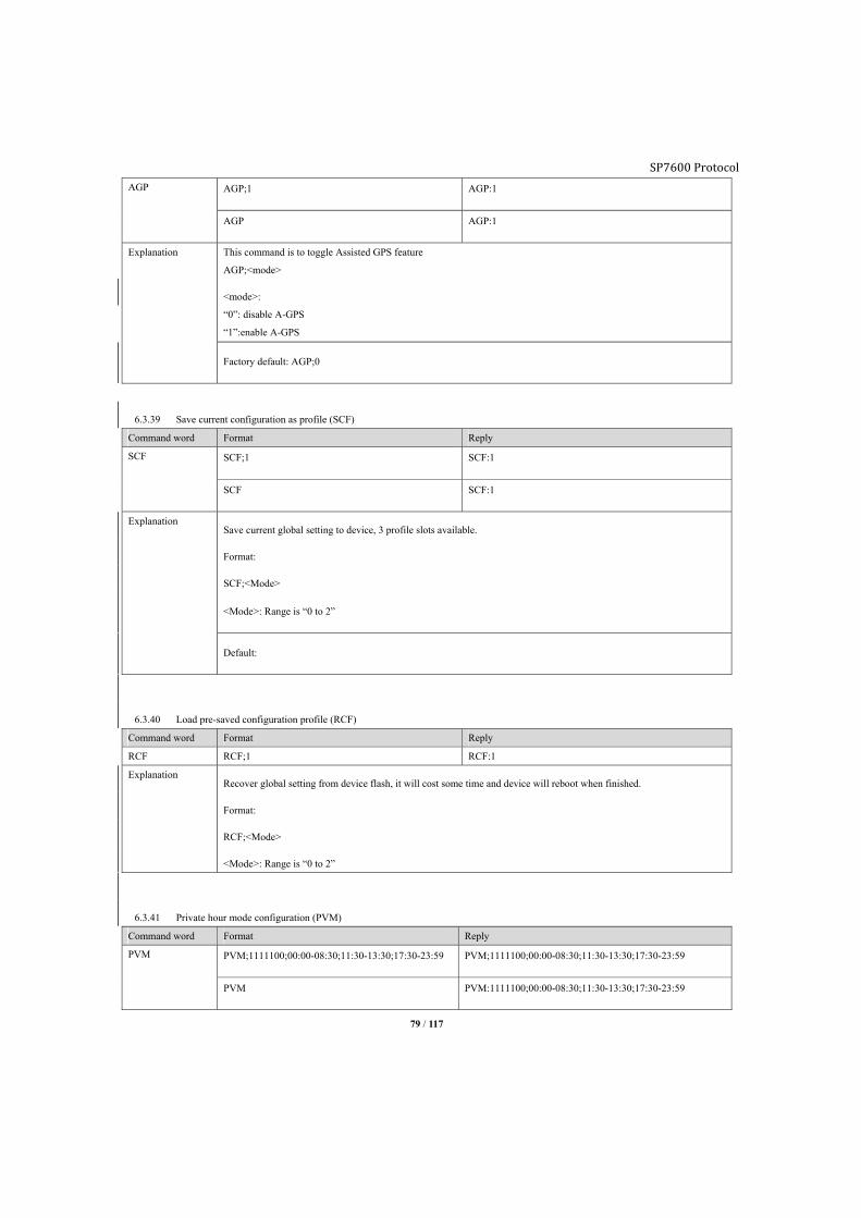
SP7600 Protocol
79 / 117
AGP AGP;1 AGP:1
AGP AGP:1
Explanation This command is to toggle Assisted GPS feature
AGP;<mode>
<mode>:
“0”: disable A-GPS
“1”:enable A-GPS
Factory default: AGP;0
6.3.39 Save current configuration as profile (SCF)
Command word Format Reply
SCF SCF;1 SCF:1
SCF SCF:1
Explanation Save current global setting to device, 3 profile slots available.
Format:
SCF;<Mode>
<Mode>: Range is “0 to 2”
Default:
6.3.40 Load pre-saved configuration profile (RCF)
Command word Format Reply
RCF RCF;1 RCF:1
Explanation Recover global setting from device flash, it will cost some time and device will reboot when finished.
Format:
RCF;<Mode>
<Mode>: Range is “0 to 2”
6.3.41 Private hour mode configuration (PVM)
Command word Format Reply
PVM PVM;1111100;00:00-08:30;11:30-13:30;17:30-23:59 PVM;1111100;00:00-08:30;11:30-13:30;17:30-23:59
PVM PVM:1111100;00:00-08:30;11:30-13:30;17:30-23:59

SP7600 Protocol
80 / 117
PVM;<mode><diid><workdaymask><hh1:mm1-hh2:mm2><hh1:mm1-hh2:mm2><hh1:mm1-hh2:mm2>
4 kinds of private mode, each mode has different trigger condition and report different to server:
Mode Name Trigger condition Report data string
0 Disable As usual
1 Full manual If digital input is “true”, device will
switch to “Full manual” private mode,
otherwise as usual
Not report GPS/GSM position,
Report device status (DTT)
2 Half manual If digital input is “true”, and under
private hour range, device will switch
to “Half manual” private mode,
otherwise as usual
Not report GPS/GSM position,
Report device status (DTT)
3 Automatically According to private hour range setting
only, device will switch to
“Automatically” private mode,
otherwise as usual
Not report GPS/GSM position,
Report device status (DTT)
4 Automatically
private activity
According to private hour range setting
only, device will switch to
“Automatically” private mode,
otherwise as usual
Report as usual,
Report device status (DTT)
Note:
4 digital input channels, range is “0 to 3”, first 2 are low level trigger, last 2 are high level trigger.
Workday mask, “1” is working day, “0” is private day.
1 1 1 1 1 0 0
Mon Tue Wed Thu Fri Sat Sun
<mode>
0: Disable private hour mode
Command format: PVM;0
1: Full manual
Command format: PVM;1;<diid>
<diid>: Digital input channel, range is “0 to 3”
2: Half-manual
Command format: PVM;2;<diid>;<workdaymask>;<hh1:mm1-hh2:mm2>..
<diid>: Digital input channel, range is “0 to 3”
<workdaymask>: Working day mask
<hh1:mm1-hh2:mm2>: Private hour period on daily basis, 3 periods valid, at least set 1 period.

SP7600 Protocol
81 / 117
3: Automatically
Command format: PVM;3;<workdaymask>;<hh1:mm1-hh2:mm2>..
<workdaymask>: Working day mask
<hh1:mm1-hh2:mm2>: Private hour period on daily basis, 3 periods valid, at least set 1 period.
4: Private activity monitoring
Command format: PVM;4;<workdaymask>;<hh1:mm1-hh2:mm2>..
<workdaymask>: Working day mask
<hh1:mm1-hh2:mm2>: Private hour period on daily basis, 3 periods valid, at least set 1 period.
Default: PVM;0
6.3.42 OBDII configuration (OBP)
Command word Format Reply
OBP OBP3;0105 OBP3:0105
Explanation OBP0 to OBP15
16 PID in total, HEX.
First byte represents OBD mode, second byte represents PID. If PID invalid then just need to fill mode code.
Parameter length: 0 to 22 bytes
Example:
OBP3;04 means reset DTC
OBP4;010C means query engine RPM
OBP16 is used to set fuel density:
Octane 90: 0.722kg/L
Octane 93: 0.725kg/L
Octane 97: 0.737kg/L
Diesel oil 0#: 0.835kg/L
Diesel oil -10#: 0.840kg/L
Diesel oil -20#: 0.843kg/L
6.3.43 OBDII events configuration (OBA)
Command word Format Reply
OBA OBA0;2;5 OBA0:2;5
Explanation Format: OBA[ID];<Parameter1>;<Parameter2>
[ID]: Range: 0 to 4
OBA0: Set engine revving event
<Parameter 1>: RPM threshold, range 0 to 10, 0 means disabled, unit is 1000/Minute.
<Parameter 2>: Duration threshold, range 0 to 60, 0 means disabled, unit is second.
OBA1: Set engine temperature event
<Parameter 1>: Temperature threshold, range 0 to 200, 0 means disabled, unit is Celsius.

SP7600 Protocol
82 / 117
<Parameter 2>: Duration threshold, range 0 to 60, 0 means disabled, unit is second.
OBA2: Set service mileage event
<Parameter 1>: Mileage threshold, range 0 to 5000000, 0 means disabled, unit is 100 meters.
<Parameter 2>: Notification threshold, range 0 to 100000, 0 means disabled, unit is 100 meters.
OBA2;0 is used to reset service mileage event
E.g.:
OBA2;20000;500
It represents service mileage is 2000Km, notification mileage is 50Km remaining, when mileage reaches 1950km,
service event will be triggered. User sends command OBA2;0 manually to reset mileage or when reaches 2000Km device
will automatically reset.
<Parameter 1>: Mileage threshold, range 0 to 5000000, 0 means disabled, unit is 100 meters.
<Parameter 2>: Notification threshold, range 0 to 100000, 0 means disabled, unit is 100 meters.
OBA3: Set engine oil event
OBA3;20000;500
It represents engine oil event is 2000Km, notification mileage is 50Km remaining, when mileage reaches 1950km,
engine oil event will be triggered. User sends command OBA3;0 manually to reset mileage or when reaches 2000Km
device will automatically reset.
<Parameter 1>: Mileage threshold, range 0 to 5000000, 0 means disabled, unit is 100 meters.
<Parameter 2>: Notification threshold, range 0 to 100000, 0 means disabled, unit is 100 meters.
OBA4: Set Tire event
OBA4;20000;500
It represents Tire event is 2000Km, notification mileage is 50Km remaining, when mileage reaches 1950km, Tire event
will be triggered. User sends command OBA4;0 manually to reset mileage or when reaches 2000Km device will
automatically reset.
<Parameter 1>: Mileage threshold, range 0 to 5000000, 0 means disabled, unit is 100 meters.
<Parameter 2>: Notification threshold, range 0 to 100000, 0 means disabled, unit is 100 meters.
Note: This is a public command for J1939 and OBDII.
6.3.44 Query ODBII (OBC)
Com
mand
word
Format Relay
OBC OBC;0105 OBC:0105
410500
Expl
anati
on
This command is used to query current OBDII status
Format
OBC;<PID>
<PID>: length 0 to 22 bytes
Send command OBC to request the Supported PID, you need to send one by one.
For example:

SP7600 Protocol
83 / 117
Bitwise encoded PIDs
Some of the PIDs in the above table cannot be explained with a simple formula. A more elaborate explanation of these data is provided
here:
Mode 1 PID 00
A request for this PID returns 4 bytes of data. Each bit, from MSB to LSB, represents one of the next 32 PIDs and is giving information
about if it is supported.
For example, if the car response is BE3EA813, it can be decoded like this:
PIDs supported [01 - 20]
Send:
*GS00,OBC;0100#
Reply:
*GS16,358173050284218,OBC:0100#
*GS16,358173050284218,OBC;R;4100BE3EA813;410098188001#
4100BE3EA813
410098188001
Hexa
decim
al
B E 3 E A 8 1 3
Binar
y
1 0 1 1 1 1 1 0 0 0 1 1 1 1 1 0 1 0 1 0 1 0 0 0 0 0 0 1 0 0 1 1
Supp
orted
?
Y
e
s
N
o
Y
e
s
Y
e
s
Y
e
s
Y
e
s
Y
e
s
N
o
N
o
N
o
Y
e
s
Y
e
s
Y
e
s
Y
e
s
Y
e
s
N
o
Y
e
s
N
o
Y
e
s
N
o
Y
e
s
N
o
N
o
N
o
N
o
N
o
N
o
Y
e
s
N
o
N
o
Y
e
s
Y
e
s
PID
numb
er
0
1
0
2
0
3
0
4
0
5
0
6
0
7
0
8
0
9
0
A
0
B
0
C
0
D
0
E
0
F
1
0
1
1
1
2
1
3
1
4
1
5
1
6
1
7
1
8
1
9
1
A
1
B
1
C
1
D
1
E
1
F
2
0
So, supported PIDs are: 01, 03, 04, 05, 06, 07, 0B,0C, 0D, 0E, 0F, 11, 13, 15, 1C, 1F and 20
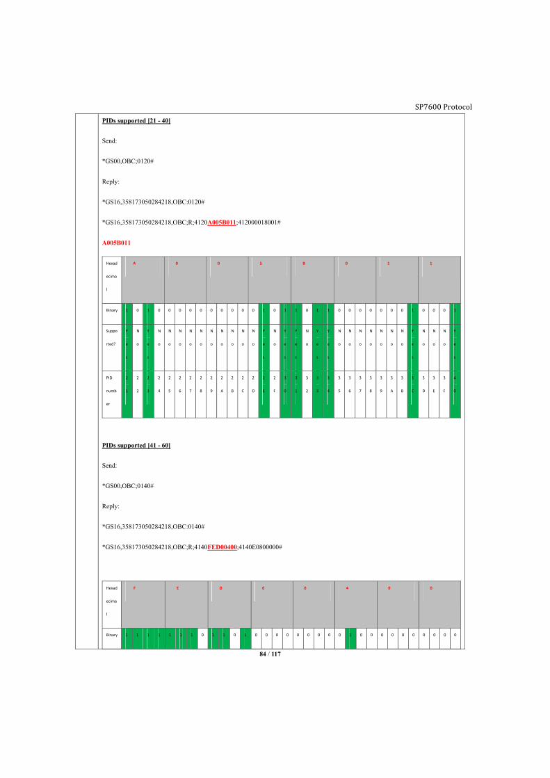
SP7600 Protocol
84 / 117
PIDs supported [21 - 40]
Send:
*GS00,OBC;0120#
Reply:
*GS16,358173050284218,OBC:0120#
*GS16,358173050284218,OBC;R;4120A005B011;412000018001#
A005B011
Hexad
ecima
l
A 0 0 5 B 0 1 1
Binary 1 0 1 0 0 0 0 0 0 0 0 0 0 1 0 1 1 0 1 1 0 0 0 0 0 0 0 1 0 0 0 1
Suppo
rted?
Y
e
s
N
o
Y
e
s
N
o
N
o
N
o
N
o
N
o
N
o
N
o
N
o
N
o
N
o
Y
e
s
N
o
Y
e
s
Y
e
s
N
o
Y
e
s
Y
e
s
N
o
N
o
N
o
N
o
N
o
N
o
N
o
Y
e
s
N
o
N
o
N
o
Y
e
s
PID
numb
er
2
1
2
2
2
3
2
4
2
5
2
6
2
7
2
8
2
9
2
A
2
B
2
C
2
D
2
E
2
F
3
0
3
1
3
2
3
3
3
4
3
5
3
6
3
7
3
8
3
9
3
A
3
B
3
C
3
D
3
E
3
F
4
0
PIDs supported [41 - 60]
Send:
*GS00,OBC;0140#
Reply:
*GS16,358173050284218,OBC:0140#
*GS16,358173050284218,OBC;R;4140FED00400;4140E0800000#
Hexad
ecima
l
F E D 0 0 4 0 0
Binary 1 1 1 1 1 1 1 0 1 1 0 1 0 0 0 0 0 0 0 0 0 1 0 0 0 0 0 0 0 0 0 0
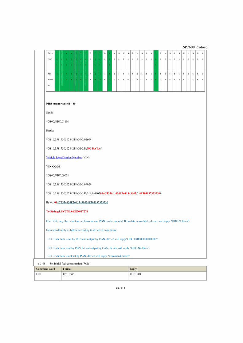
SP7600 Protocol
85 / 117
Suppo
rted?
Y
e
s
Y
e
s
Y
e
s
Y
e
s
Y
e
s
Y
e
s
Y
e
s
N
o
Y
e
s
Y
e
s
N
o
Y
e
s
N
o
N
o
N
o
N
o
N
o
N
o
N
o
N
o
N
o
Y
e
s
N
o
N
o
N
o
N
o
N
o
N
o
N
o
N
o
N
o
N
o
PID
numb
er
4
1
4
2
4
3
4
4
4
5
4
6
4
7
4
8
4
9
4
A
4
B
4
C
4
D
4
E
4
F
5
0
5
1
5
2
5
3
5
4
5
5
5
6
5
7
5
8
5
9
5
A
5
B
5
C
5
D
5
E
5
F
6
0
PIDs supported [61 - 80]
Send:
*GS00,OBC;0160#
Reply:
*GS16,358173050284218,OBC:0160#
*GS16,358173050284218,OBC;R;NO DATA#
Vehicle Identification Number (VIN)
VIN CODE:
*GS00,OBC;0902#
*GS16,358173050284218,OBC:0902#
*GS16,358173050284218,OBC;R;014;0:4902014C5356;1:434E3641343045;2:4E303137323736#
Bytes: 014C5356434E36413430454E303137323736
To String:LSVCN6A40EN017276
ForJ1939, only the data item set bycommand PGN can be queried. If no data is available, device will reply “OBC:NoData”.
Device will reply as below according to different conditions:
(1)Data item is set by PGN and output by CAN, device will reply“OBC:03ff000000000000”.
(2)Data item is setby PGN but not output by CAN, device will reply “OBC:No Data”.
(3)Data item is not set by PGN, device will reply “Command error!”.
6.3.45 Set initial fuel consumption (FCI)
Command word Format Reply
FCI FCI;1000 FCI:1000
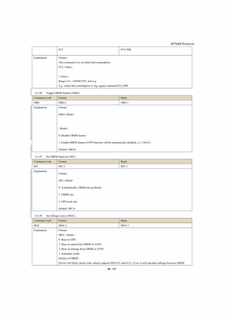
SP7600 Protocol
86 / 117
FCI FCI:1000
Explanation Format:
This command is to set initial fuel consumption
FCI;<Value>
<Value>:
Range is 0 – 4294967295, uint is g
E.g.: initial fuel consumption is 1kg, equals command FCI;1000
6.3.46 Toggle OBDII features (OBO)
Command word Format Reply
OBO OBO;1 OBO:1
Explanation Format:
OBO;<Mode>
<Mode>:
0: Disable OBDII feature
1: Enable OBDII feature (J1939 function will be automatically disabled, i.e. CAN;0.)
Default: OBO:0
6.3.47 Set OBDII baud rate (SPC)
Command word Format Reply
SPC SPC;1 SPC:1
Explanation Format:
SPC;<Mode>
0: Automatically, OBDII rate preferred.
1: OBDII rate
2: GPS track rate
Default: SPC;0
6.3.48 Set mileage source (MGC)
Command word Format Reply
MGC MGC;1 MGC:1
Explanation Format:
MGC;<Mode>
0: Base on GPS
1: Base on speed from OBDII or J1939.
2: Base on mileage from OBDII or J1939.
3: Automatic mode:
Priority of OBDII:
Device will firstly check if the vehicle supports PID 0121 and 0131, if yes, it will calculate mileage based on OBDII

SP7600 Protocol
87 / 117
mileage. Otherwise, device will check if vehicle supports PID 010D (OBDII speed) and calculate mileage base on OBDII
speed. Otherwise, it’ll calculate base on GPS.
Priority of J1939:
Device will firstly check if there is J1939 data. If yes, it will calculate mileage based on the mileage from J1939. If there
is no mileage from J1939, device will calculate mileage based on speed from J1939. If there is no J1939 data, device will
calculate mileage based on GPS.
Default:
MGC:3
6.3.49 Query 3 axis sensor calibration status (CAC)
Command word Format Reply
CAC CAC CAC:1;1
Explanation This command is query calibration status of motion sensor.
Returned value:
CAC:<stop calibration>;<moving calibration>
<stop calibration>:
“0” Calibrated
“1” No calibrated
<moving calibration>:
“0” Calibrated
“1” No calibrated
Note: Calibration is being done by tracker itself,
only if stop calibration is being done, tracker able to detect turn over event.
only if moving calibration is being done, tracker able to detect harsh behavior event without GPS fix.
6.3.50 Server shift configuration (SVT)
Command word Format Reply
SVT SVT;1800;15 SVT:1800;15
SVT SVT:1800;15
Explanation This command is to set backup server timeout.
Format
SVT;<shift timer>;<ACK timeout>
Explanation
<Shift timer>: When timer is up, device will try to reconnect with main server, unit is second, range is “60 to 65535”.
<ACK timeout>: Timeout threshold for server ACK packet, unit is second, range is “15 to 60”.
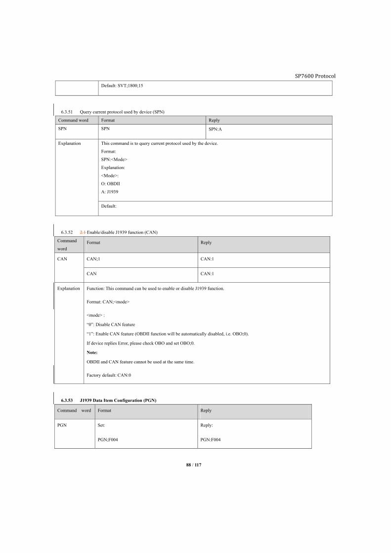
SP7600 Protocol
88 / 117
Default: SVT;1800;15
6.3.51 Query current protocol used by device (SPN)
Command word Format Reply
SPN SPN SPN:A
Explanation This command is to query current protocol used by the device.
Format:
SPN:<Mode>
Explanation:
<Mode>:
O: OBDII
A: J1939
Default:
6.3.52 2.1 Enable/disable J1939 function (CAN)
Command
word Format Reply
CAN CAN;1 CAN:1
CAN CAN:1
Explanation Function: This command can be used to enable or disable J1939 function.
Format: CAN;<mode>
<mode> :
“0”: Disable CAN feature
“1”: Enable CAN feature (OBDII function will be automatically disabled, i.e. OBO;0).
If device replies Error, please check OBO and set OBO;0.
Note:
OBDII and CAN feature cannot be used at the same time.
Factory default: CAN:0
6.3.53 J1939 Data Item Configuration (PGN)
Command word Format Reply
PGN Set:
PGN;F004
Reply:
PGN:F004

SP7600 Protocol
89 / 117
PGN1;FEEE
PGN2;FE6C
PGN3;FEE9
PGN4;FEE0
Query:
PGN3
PGN1:FEEE
PGN2:FE6C
PGN3:FEE9
PGN4:FEE0
Reply:
PGN3:FEE9
Explanation Function: This command can be used to set J1939 data item. The data item set by this command will be report to
server.
Format: PGN[id];<para.1>
[id]: 0-7
< para.1>: Hex format. E.g. F004
Frequently used PGN:
PGN_61444 0xF004 // Electronic engine controller (used to calculate RPM), transmission rate: 100ms
PGN_65262 0xFEEE //Engine temperature (used to calculate engine temperature), transmission rate: 1s
PGN_65132 0xFE6C //Automobile data recorder (used to calculate vehicle speed), transmission rate:
50ms
PGN_65257 0xFEE9 //Fuel consumption (used to calculate fuel consumption)
PGN_65248 0xFEE0 //Traveling distance (used to calculate mileage), transmission rate: 100ms
PGN_65226 0xFECA //DTC, transmission rate: 1S
Note: These data items are related to alarm, mileage and fuel consumption. For getting relevant alarm, mileage
and fuel consumption, related data item must be set by PGN.
Factory default:
PGN:F004
PGN1:FEEE
PGN2:FE6C
PGN3:FEE9

SP7600 Protocol
90 / 117
PGN4:FEE0
GPN5:FECA
6.4. Public command
6.4.1 Set user phone number (UNO)
Command word Format Reply
UNO UNO0;+8613912345678
UNO1;+8613912345678
UNO0:+8613912345678
UNO1:+8613912345678
Delete user number:
UNO0;
UNO1;
Reply:
UNO0:
UNO1:
Explanation This command is set up 2 users phone number
2 user numbers are available: UNO0 and UNO1.
With the correct password, any phone number is able to use this command.
Default:
UNO0:
UNO1:
6.4.2 Set user command password (UPW)
Command word Format Reply
UPW Set user0 password: UPW0;1234
Set user1 password: UPW1;2234
UPW0:1234
UPW1:2234
Explanation Fix 4 digits, range is “0000 to 9999”
UPW0: Set user0 password
UPW1: Set user1 password
Default:
UPW0;1234
UPW1;1234
6.4.3 Motion sensor configuration (MOT)
Command word Format Reply
MOT MOT;0 MOT:0
MOT MOT:0
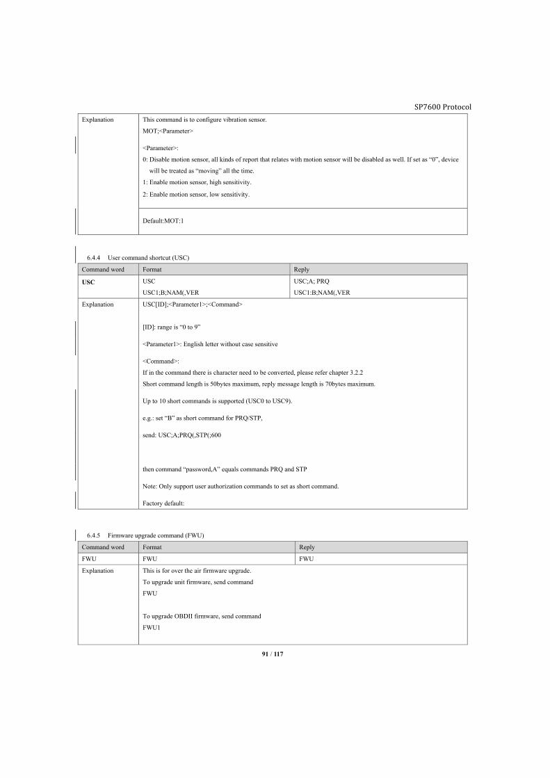
SP7600 Protocol
91 / 117
Explanation This command is to configure vibration sensor.
MOT;<Parameter>
<Parameter>:
0: Disable motion sensor, all kinds of report that relates with motion sensor will be disabled as well. If set as “0”, device
will be treated as “moving” all the time.
1: Enable motion sensor, high sensitivity.
2: Enable motion sensor, low sensitivity.
Default:MOT:1
6.4.4 User command shortcut (USC)
Command word Format Reply
USC USC
USC1;B;NAM(,VER
USC;A; PRQ
USC1:B;NAM(,VER
Explanation USC[ID];<Parameter1>;<Command>
[ID]: range is “0 to 9”
<Parameter1>: English letter without case sensitive
<Command>:
If in the command there is character need to be converted, please refer chapter 3.2.2
Short command length is 50bytes maximum, reply message length is 70bytes maximum.
Up to 10 short commands is supported (USC0 to USC9).
e.g.: set “B” as short command for PRQ/STP,
send: USC;A;PRQ(,STP(;600
then command “password,A” equals commands PRQ and STP
Note: Only support user authorization commands to set as short command.
Factory default:
6.4.5 Firmware upgrade command (FWU)
Command word Format Reply
FWU FWU FWU
Explanation This is for over the air firmware upgrade.
To upgrade unit firmware, send command
FWU
To upgrade OBDII firmware, send command
FWU1
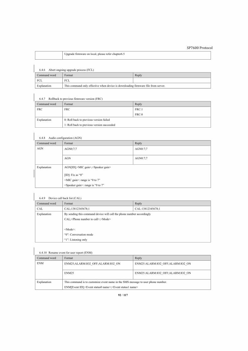
SP7600 Protocol
92 / 117
Upgrade firmware on local, please refer chapter6.5
6.4.6 Abort ongoing upgrade process (FCL)
Command word Format Reply
FCL FCL
Explanation This command only effective when device is downloading firmware file from server.
6.4.7 Rollback to previous firmware version (FRC)
Command word Format Reply
FRC FRC FRC:1
FRC:0
Explanation 0: Roll back to previous version failed
1: Roll back to previous version succeeded
6.4.8 Audio configuration (AGN)
Command word Format Reply
AGN AGN0;7;7 AGN0:7;7
AGN AGN0:7;7
Explanation AGN[ID];<MIC gain>,<Speaker gain>
[ID]: Fix as “0”
<MIC gain>: range is “0 to 7”
<Speaker gain>: range is “0 to 7”
6.4.9 Device call back list (CAL)
Command word Format Reply
CAL CAL;13812345678;1 CAL:13812345678;1
Explanation By sending this command device will call the phone number accordingly
CAL;<Phone number to call>;<Mode>
<Mode>:
“0”: Conversation mode
“1”: Listening only
6.4.10 Rename event for user report (ENM)
Command word Format Reply
ENM ENM25;ALARM:IO2_OFF;ALARM:IO2_ON ENM25:ALARM:IO2_OFF;ALARM:IO2_ON
ENM25 ENM25:ALARM:IO2_OFF;ALARM:IO2_ON
Explanation This command is to customize event name in the SMS message to user phone number.
ENM[Event ID];<Event status0 name>;<Event status1 name>
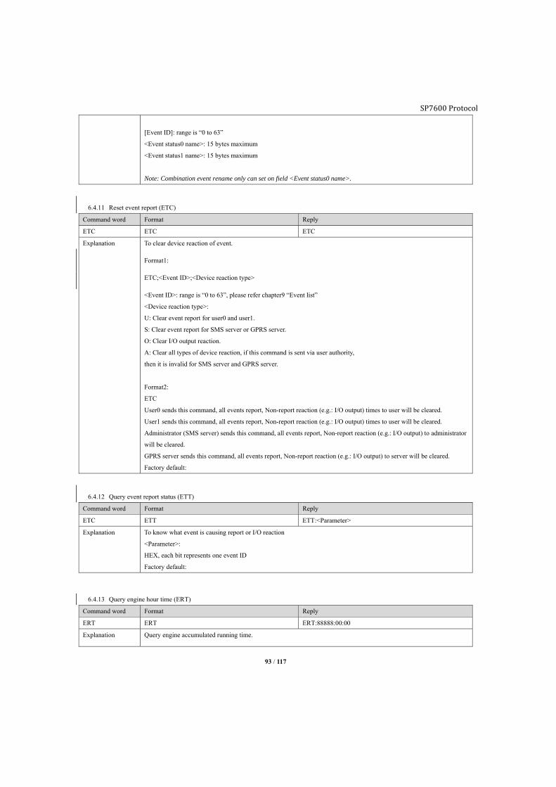
SP7600 Protocol
93 / 117
[Event ID]: range is “0 to 63”
<Event status0 name>: 15 bytes maximum
<Event status1 name>: 15 bytes maximum
Note: Combination event rename only can set on field <Event status0 name>.
6.4.11 Reset event report (ETC)
Command word Format Reply
ETC ETC ETC
Explanation To clear device reaction of event.
Format1:
ETC;<Event ID>;<Device reaction type>
<Event ID>: range is “0 to 63”, please refer chapter9 “Event list”
<Device reaction type>:
U: Clear event report for user0 and user1.
S: Clear event report for SMS server or GPRS server.
O: Clear I/O output reaction.
A: Clear all types of device reaction, if this command is sent via user authority,
then it is invalid for SMS server and GPRS server.
Format2:
ETC
User0 sends this command, all events report, Non-report reaction (e.g.: I/O output) times to user will be cleared.
User1 sends this command, all events report, Non-report reaction (e.g.: I/O output) times to user will be cleared.
Administrator (SMS server) sends this command, all events report, Non-report reaction (e.g.: I/O output) to administrator
will be cleared.
GPRS server sends this command, all events report, Non-report reaction (e.g.: I/O output) to server will be cleared.
Factory default:
6.4.12 Query event report status (ETT)
Command word Format Reply
ETC ETT ETT:<Parameter>
Explanation To know what event is causing report or I/O reaction
<Parameter>:
HEX, each bit represents one event ID
Factory default:
6.4.13 Query engine hour time (ERT)
Command word Format Reply
ERT ERT ERT:88888:00:00
Explanation Query engine accumulated running time.
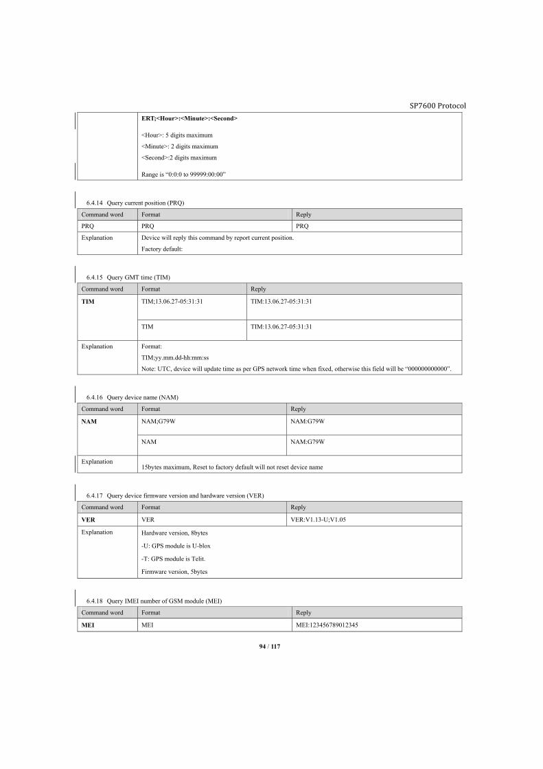
SP7600 Protocol
94 / 117
ERT;<Hour>:<Minute>:<Second>
<Hour>: 5 digits maximum
<Minute>: 2 digits maximum
<Second>:2 digits maximum
Range is “0:0:0 to 99999:00:00”
6.4.14 Query current position (PRQ)
Command word Format Reply
PRQ PRQ PRQ
Explanation Device will reply this command by report current position.
Factory default:
6.4.15 Query GMT time (TIM)
Command word Format Reply
TIM TIM;13.06.27-05:31:31 TIM:13.06.27-05:31:31
TIM TIM:13.06.27-05:31:31
Explanation Format:
TIM;yy.mm.dd-hh:mm:ss
Note: UTC, device will update time as per GPS network time when fixed, otherwise this field will be “000000000000”.
6.4.16 Query device name (NAM)
Command word Format Reply
NAM NAM;G79W NAM:G79W
NAM NAM:G79W
Explanation 15bytes maximum, Reset to factory default will not reset device name
6.4.17 Query device firmware version and hardware version (VER)
Command word Format Reply
VER VER VER:V1.13-U;V1.05
Explanation Hardware version, 8bytes
-U: GPS module is U-blox
-T: GPS module is Telit.
Firmware version, 5bytes
6.4.18 Query IMEI number of GSM module (MEI)
Command word Format Reply
MEI MEI MEI:123456789012345

SP7600 Protocol
95 / 117
Explanation The IMEI number is used by a GSM network to Identify valid devices, 15 digits.
In this case it is the IMEI number of tracker GSM module.
6.4.19 Query IMSI number of SIM card (MSI)
Command word Format Reply
MSI MSI MSI: 460079148126057
Explanation An IMSI is usually presented as a 15 digit long number, The first 3 digits are the mobile country code (MCC), which are
followed by the mobile network code (MNC), either 2 digits (European standard) or 3 digits (North American standard).
The length of the MNC depends on the value of the MCC. The remaining digits are the mobile subscription
IDentification number (MSIN) within the network's customer base.
6.4.20 Query ICCID number of SIM card (CID)
Command word Format Reply
CID CID CID:898600D1191149037057
Explanation Each SIM is internationally Identifier by its integrated circuit card identifier (ICCID). ICCID are stored in the SIM cards
and are also engraved or printed on the SIM card body during a process called personalization.
6.4.21 Query GSM signal strength (CSQ)
Command word Format Reply
CSQ CSQ CSQ:5
Explanation 5: GSM signal strength, range is “0 to 5”
6.4.22 Query GSM network status (REG)
Command word Format Reply
REG REG REG:1
Explanation 0:Fail to register, device is not trying to register to any mobile network
1:Register successfully
2:Fail to register, but device is trying to register to mobile network
3:Register intention is being rejected by mobile network
4:Unknown reason
5:Register to roaming network successfully
6.4.23 Reset SMS counter (SCC)
Command word Format Reply
SCC SCC SCC
Explanation SMS counter will be reset to zero
6.4.24 Query SMS counter (SCR)
Command word Format Reply
SCR SCR SCR:10;100
Explanation Parameter1:“10”: SMS number device received
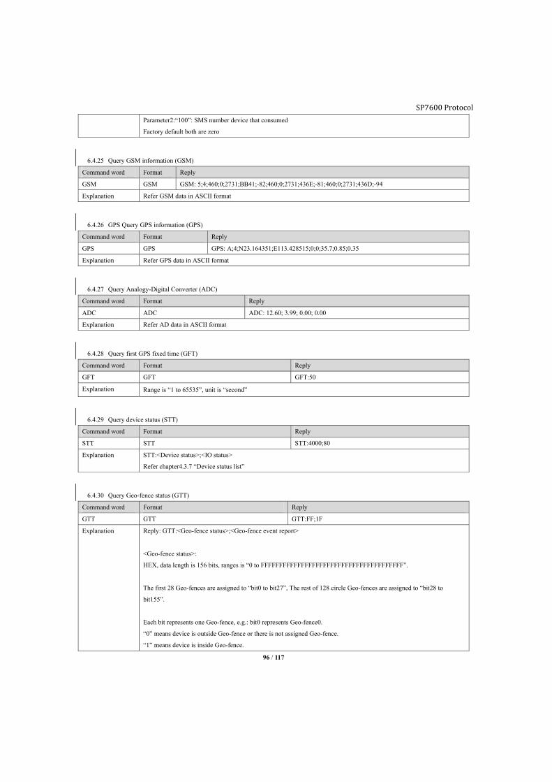
SP7600 Protocol
96 / 117
Parameter2:“100”: SMS number device that consumed
Factory default both are zero
6.4.25 Query GSM information (GSM)
Command word Format Reply
GSM GSM GSM: 5;4;460;0;2731;BB41;-82;460;0;2731;436E;-81;460;0;2731;436D;-94
Explanation Refer GSM data in ASCII format
6.4.26 GPS Query GPS information (GPS)
Command word Format Reply
GPS GPS GPS: A;4;N23.164351;E113.428515;0;0;35.7;0.85;0.35
Explanation Refer GPS data in ASCII format
6.4.27 Query Analogy-Digital Converter (ADC)
Command word Format Reply
ADC ADC ADC: 12.60; 3.99; 0.00; 0.00
Explanation Refer AD data in ASCII format
6.4.28 Query first GPS fixed time (GFT)
Command word Format Reply
GFT GFT GFT:50
Explanation Range is “1 to 65535”, unit is “second”
6.4.29 Query device status (STT)
Command word Format Reply
STT STT STT:4000;80
Explanation STT:<Device status>;<IO status>
Refer chapter4.3.7 “Device status list”
6.4.30 Query Geo-fence status (GTT)
Command word Format Reply
GTT GTT GTT:FF;1F
Explanation Reply: GTT:<Geo-fence status>;<Geo-fence event report>
<Geo-fence status>:
HEX, data length is 156 bits, ranges is “0 to FFFFFFFFFFFFFFFFFFFFFFFFFFFFFFFFFFFFFFF”.
The first 28 Geo-fences are assigned to “bit0 to bit27”, The rest of 128 circle Geo-fences are assigned to “bit28 to
bit155”.
Each bit represents one Geo-fence, e.g.: bit0 represents Geo-fence0.
“0” means device is outside Geo-fence or there is not assigned Geo-fence.
“1” means device is inside Geo-fence.
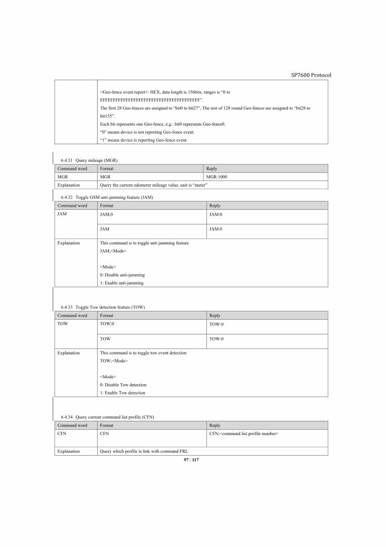
SP7600 Protocol
97 / 117
<Geo-fence event report>: HEX, data length is 156bits, ranges is “0 to
FFFFFFFFFFFFFFFFFFFFFFFFFFFFFFFFFFFFFFF”.
The first 28 Geo-fences are assigned to “bit0 to bit27”, The rest of 128 round Geo-fences are assigned to “bit28 to
bit155”.
Each bit represents one Geo-fence, e.g.: bit0 represents Geo-fence0.
“0” means device is not reporting Geo-fence event.
“1” means device is reporting Geo-fence event.
6.4.31 Query mileage (MGR)
Command word Format Reply
MGR MGR MGR:1000
Explanation Query the current odometer mileage value, unit is “meter”
6.4.32 Toggle GSM anti-jamming feature (JAM)
Command word Format Reply
JAM JAM;0 JAM:0
JAM JAM:0
Explanation This command is to toggle anti jamming feature
JAM;<Mode>
<Mode>
0: Disable anti-jamming
1: Enable anti-jamming
6.4.33 Toggle Tow detection feature (TOW)
Command word Format Reply
TOW TOW;0 TOW:0
TOW TOW:0
Explanation This command is to toggle tow event detection
TOW;<Mode>
<Mode>
0: Disable Tow detection
1: Enable Tow detection
6.4.34 Query current command list profile (CFN)
Command word Format Reply
CFN CFN CFN;<command list profile number>
Explanation Query which profile is link with command FRL
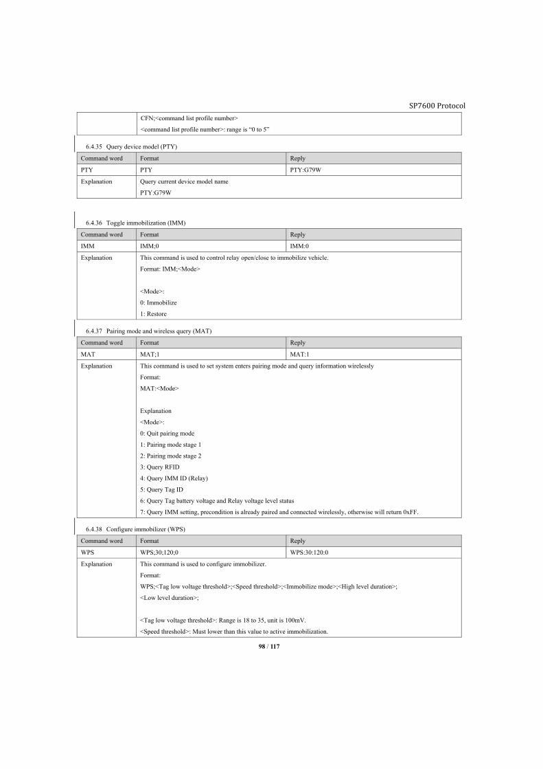
SP7600 Protocol
98 / 117
CFN;<command list profile number>
<command list profile number>: range is “0 to 5”
6.4.35 Query device model (PTY)
Command word Format Reply
PTY PTY PTY:G79W
Explanation Query current device model name
PTY:G79W
6.4.36 Toggle immobilization (IMM)
Command word Format Reply
IMM IMM;0 IMM:0
Explanation This command is used to control relay open/close to immobilize vehicle.
Format: IMM;<Mode>
<Mode>:
0: Immobilize
1: Restore
6.4.37 Pairing mode and wireless query (MAT)
Command word Format Reply
MAT MAT;1 MAT:1
Explanation This command is used to set system enters pairing mode and query information wirelessly
Format:
MAT:<Mode>
Explanation
<Mode>:
0: Quit pairing mode
1: Pairing mode stage 1
2: Pairing mode stage 2
3: Query RFID
4: Query IMM ID (Relay)
5: Query Tag ID
6: Query Tag battery voltage and Relay voltage level status
7: Query IMM setting, precondition is already paired and connected wirelessly, otherwise will return 0xFF.
6.4.38 Configure immobilizer (WPS)
Command word Format Reply
WPS WPS;30;120;0 WPS:30:120:0
Explanation This command is used to configure immobilizer.
Format:
WPS;<Tag low voltage threshold>;<Speed threshold>;<Immobilize mode>;<High level duration>;
<Low level duration>;
<Tag low voltage threshold>: Range is 18 to 35, unit is 100mV.
<Speed threshold>: Must lower than this value to active immobilization.
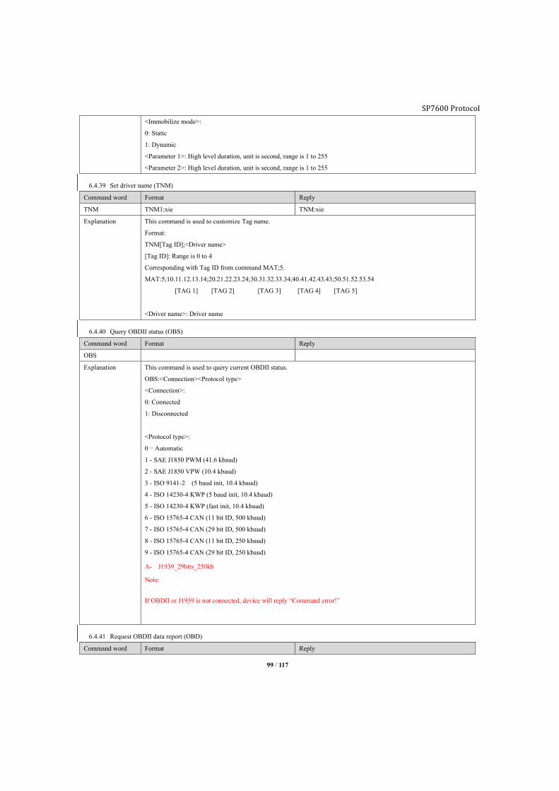
SP7600 Protocol
99 / 117
<Immobilize mode>:
0: Static
1: Dynamic
<Parameter 1>: High level duration, unit is second, range is 1 to 255
<Parameter 2>: High level duration, unit is second, range is 1 to 255
6.4.39 Set driver name (TNM)
Command word Format Reply
TNM TNM1;xie TNM:xie
Explanation This command is used to customize Tag name.
Format:
TNM[Tag ID];<Driver name>
[Tag ID]: Range is 0 to 4
Corresponding with Tag ID from command MAT;5.
MAT:5;10.11.12.13.14;20.21.22.23.24;30.31.32.33.34;40.41.42.43.43;50.51.52.53.54
[TAG 1] [TAG 2] [TAG 3] [TAG 4] [TAG 5]
<Driver name>: Driver name
6.4.40 Query OBDII status (OBS)
Command word Format Reply
OBS
Explanation This command is used to query current OBDII status.
OBS:<Connection><Protocol type>
<Connection>:
0: Connected
1: Disconnected
<Protocol type>:
0–Automatic
1 - SAE J1850 PWM (41.6 kbaud)
2 - SAE J1850 VPW (10.4 kbaud)
3 - ISO 9141-2 (5 baud init, 10.4 kbaud)
4 - ISO 14230-4 KWP (5 baud init, 10.4 kbaud)
5 - ISO 14230-4 KWP (fast init, 10.4 kbaud)
6 - ISO 15765-4 CAN (11 bit ID, 500 kbaud)
7 - ISO 15765-4 CAN (29 bit ID, 500 kbaud)
8 - ISO 15765-4 CAN (11 bit ID, 250 kbaud)
9 - ISO 15765-4 CAN (29 bit ID, 250 kbaud)
A- J1939_29bits_250kb
Note:
If OBDII or J1939 is not connected, device will reply “Command error!”
6.4.41 Request OBDII data report (OBD)
Command word Format Reply
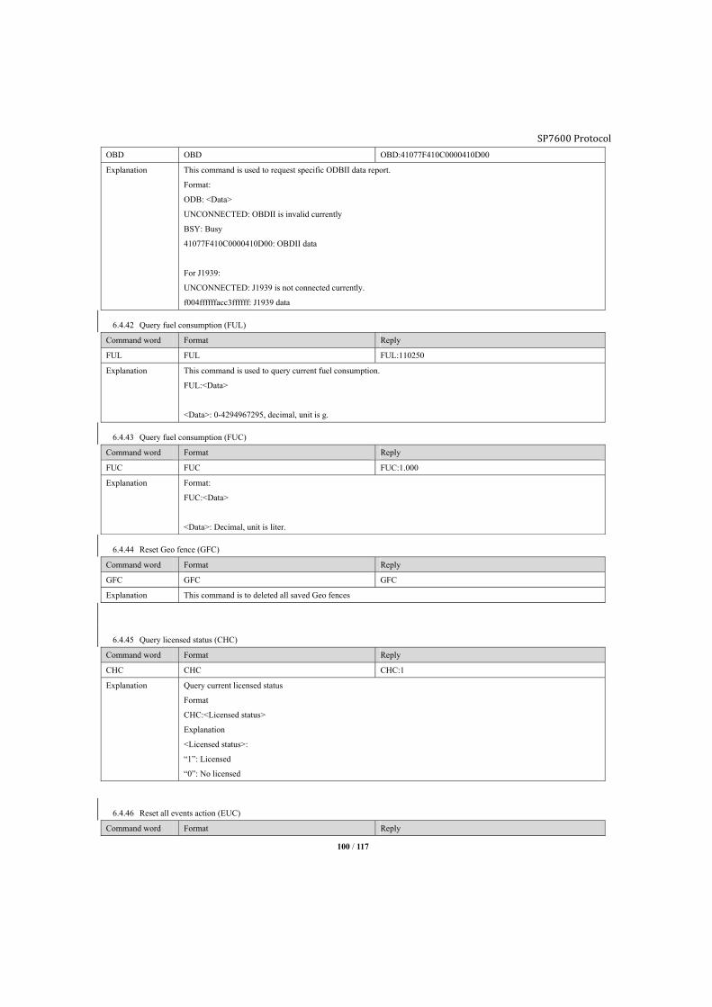
SP7600 Protocol
100 / 117
OBD OBD OBD:41077F410C0000410D00
Explanation This command is used to request specific ODBII data report.
Format:
ODB: <Data>
UNCONNECTED: OBDII is invalid currently
BSY: Busy
41077F410C0000410D00: OBDII data
For J1939:
UNCONNECTED: J1939 is not connected currently.
f004ffffffacc3ffffff: J1939 data
6.4.42 Query fuel consumption (FUL)
Command word Format Reply
FUL FUL FUL:110250
Explanation This command is used to query current fuel consumption.
FUL:<Data>
<Data>: 0-4294967295, decimal, unit is g.
6.4.43 Query fuel consumption (FUC)
Command word Format Reply
FUC FUC FUC:1.000
Explanation Format:
FUC:<Data>
<Data>: Decimal, unit is liter.
6.4.44 Reset Geo fence (GFC)
Command word Format Reply
GFC GFC GFC
Explanation This command is to deleted all saved Geo fences
6.4.45 Query licensed status (CHC)
Command word Format Reply
CHC CHC CHC:1
Explanation Query current licensed status
Format
CHC:<Licensed status>
Explanation
<Licensed status>:
“1”: Licensed
“0”: No licensed
6.4.46 Reset all events action (EUC)
Command word Format Reply
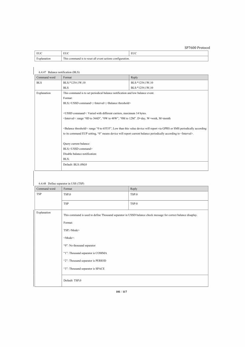
SP7600 Protocol
101 / 117
EUC EUC EUC
Explanation This command is to reset all event actions configuration.
6.4.47 Balance notification (BLS)
Command word Format Reply
BLS BLS;*125#;1W;10
BLS
BLS:*125#;1W;10
BLS:*125#;1W;10
Explanation This command is to set periodical balance notification and low balance event.
Format:
BLS;<USSD command>;<Interval>;<Balance threshold>
<USSD command>: Varied with different carriers, maximum 14 bytes.
<Interval>: range “0D to 366D”, “0W to 48W”, “0M to 12M”. D=day, W=week, M=month
<Balance threshold>: range “0 to 65535”, Low than this value device will report via GPRS or SMS periodically according
to its command EUP setting, “0” means device will report current balance periodically according to <Interval>.
Query current balance:
BLS;<USSD command>
Disable balance notification:
BLS;
Default: BLS:;0M;0
6.4.48 Define separator in USS (TSP)
Command word Format Reply
TSP TSP;0 TSP:0
TSP TSP:0
Explanation This command is used to define Thousand separator in USSD balance check message for correct balance disaplay.
Format:
TSP;<Mode>
<Mode>:
“0”: No thousand separator
“1”: Thousand separator is COMMA
“2”: Thousand separator is PERIOD
“3”: Thousand separator is SPACE
Default: TSP;0
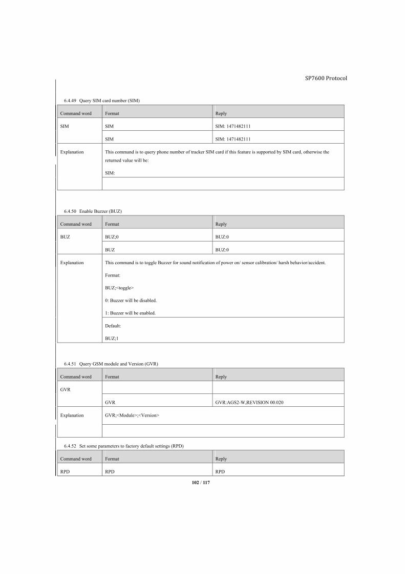
SP7600 Protocol
102 / 117
6.4.49 Query SIM card number (SIM)
Command word Format Reply
SIM SIM SIM: 1471482111
SIM SIM: 1471482111
Explanation This command is to query phone number of tracker SIM card if this feature is supported by SIM card, otherwise the
returned value will be:
SIM:
6.4.50 Enable Buzzer (BUZ)
Command word Format Reply
BUZ BUZ;0 BUZ:0
BUZ BUZ:0
Explanation This command is to toggle Buzzer for sound notification of power on/ sensor calibration/ harsh behavior/accident.
Format:
BUZ;<toggle>
0: Buzzer will be disabled.
1: Buzzer will be enabled.
Default:
BUZ;1
6.4.51 Query GSM module and Version (GVR)
Command word Format Reply
GVR
GVR GVR:AGS2-W,REVISION 00.020
Explanation GVR;<Module>;<Version>
6.4.52 Set some parameters to factory default settings (RPD)
Command word Format Reply
RPD RPD RPD
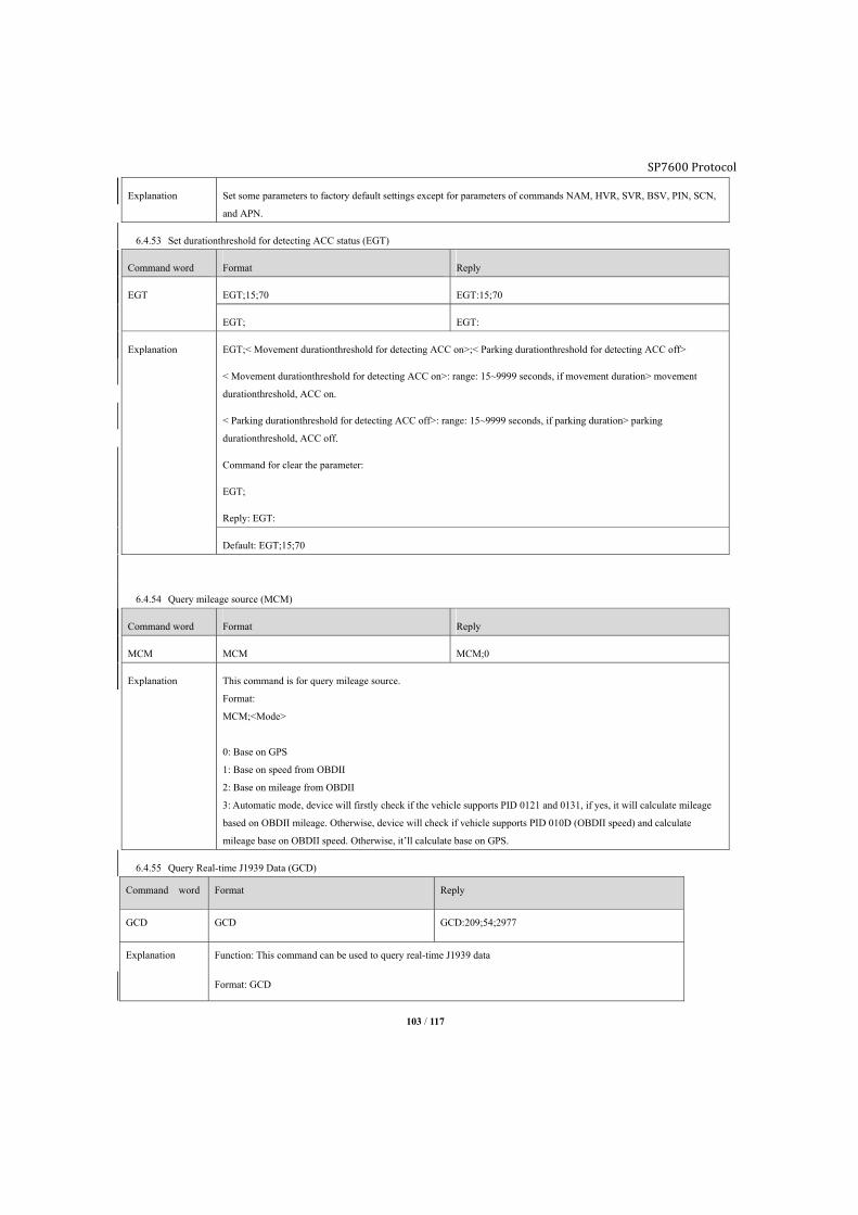
SP7600 Protocol
103 / 117
Explanation Set some parameters to factory default settings except for parameters of commands NAM, HVR, SVR, BSV, PIN, SCN,
and APN.
6.4.53 Set durationthreshold for detecting ACC status (EGT)
Command word Format Reply
EGT EGT;15;70 EGT:15;70
EGT; EGT:
Explanation EGT;< Movement durationthreshold for detecting ACC on>;< Parking durationthreshold for detecting ACC off>
< Movement durationthreshold for detecting ACC on>: range: 15~9999 seconds, if movement duration> movement
durationthreshold, ACC on.
< Parking durationthreshold for detecting ACC off>: range: 15~9999 seconds, if parking duration> parking
durationthreshold, ACC off.
Command for clear the parameter:
EGT;
Reply: EGT:
Default: EGT;15;70
6.4.54 Query mileage source (MCM)
Command word Format Reply
MCM MCM MCM;0
Explanation This command is for query mileage source.
Format:
MCM;<Mode>
0: Base on GPS
1: Base on speed from OBDII
2: Base on mileage from OBDII
3: Automatic mode, device will firstly check if the vehicle supports PID 0121 and 0131, if yes, it will calculate mileage
based on OBDII mileage. Otherwise, device will check if vehicle supports PID 010D (OBDII speed) and calculate
mileage base on OBDII speed. Otherwise, it’ll calculate base on GPS.
6.4.55 Query Real-time J1939 Data (GCD)
Command word Format Reply
GCD GCD GCD:209;54;2977
Explanation Function: This command can be used to query real-time J1939 data
Format: GCD

SP7600 Protocol
104 / 117
Device reply: GCD:<vehicle speed>;<engine temperature>;<RPM>;<Fuel consumption>;<Mileage>
GCD:175;3;8027
<vehicle speed>: unit: Km/h
<engine temperature>: unit:degree centigrade
<RPM>: rpm
<Fuel consumption>: L
<Mileage>: KM
Note; This command can be used to query some important real-time data of OBDII and J1939.
2. Send command to enable the device entering sleeping mode CSL
Command word Format Reply
CLS Setup:
CLS;1
Reply:
CLS:1
Explanation Function:Send command to enable the device entering sleeping mode
Format:CSL;<Mode>
<Format>:
0:null. When connected with external power, this command cannot be executed, when disconnected with
external power, GPRS cannot send this command.
1:Enable the device entering sleeping mode;
When connected with external power, this command is invalid;
When send this command, the GPO will be GPO;0;0;automatically, when connected with external power, it will
detect CLS is 0 or 1, if it is 1, GPO will resume to its original status, and then clear CLS as 0. Among the period
of sending CLS;1, it executes GPO setup, it will clear CLS as 0.
Factory default:No
6.5. Firmware upgrade During over the air firmware upgrade process, it will not affect device current working status, and firmware download supports “pause and
resume”. Device receives upgrade command, it will download firmware from server over GPRS, when firmware download finished device will
reboot itself to initial upgrade process. If new firmware is faulty device will restore to original firmware automatically.
■Command over GPRS:
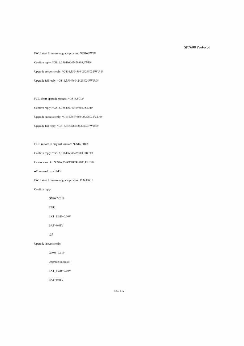
105 / 117
FWU, start firmware upgrade process: *GS16,FWU#
Confirm reply: *GS16,356496042429803,FWU#
Upgrade success reply: *GS16,356496042429803,FWU:1#
Upgrade fail reply: *GS16,356496042429803,FWU:0#
FCL, abort upgrade process: *GS16,FCL#
Confirm reply: *GS16,356496042429803,FCL:1#
Upgrade success reply: *GS16,356496042429803,FCL:0#
Upgrade fail reply: *GS16,356496042429803,FWU:0#
FRC, restore to original version: *GS16,FRC#
Confirm reply: *GS16,356496042429803,FRC:1#
Cannot execute: *GS16,356496042429803,FRC:0#
■Command over SMS:
FWU, start firmware upgrade process: 1234,FWU
Confirm reply:
G79W V2.19
FWU
EXT_PWR=0.00V
BAT=0.01V
#27
Upgrade success reply:
G79W V2.19
Upgrade Success!
EXT_PWR=0.00V
BAT=0.01V
SP7600 Protocol

SP7600 Protocol
106 / 117
#28
Upgrade fail reply:
G79W V2.19
Upgrade UnSuccess!
EXT_PWR=0.00V
BAT=0.01V
#28
FCL, abort upgrade process: 1234,FCL
Confirm reply:
G79W V2.19
FCL:1
EXT_PWR=0.00V
BAT=0.01V
#27
Cannot execute:
G79W V2.19
FCL:0
EXT_PWR=0.00V
BAT=0.01V
#27
Upgrade success reply:
G79W V2.19
Upgrade UnSuccess!
EXT_PWR=0.00V
BAT=0.01V
#28
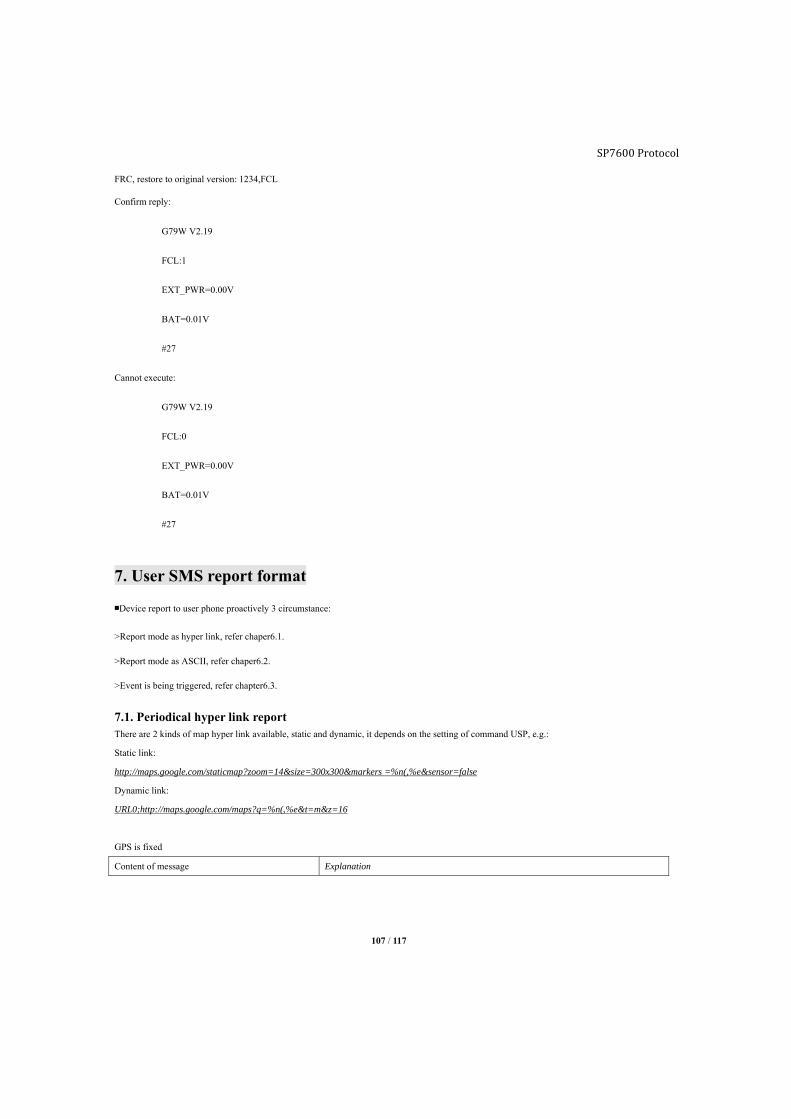
107 / 117
FRC, restore to original version: 1234,FCL
Confirm reply:
G79W V2.19
FCL:1
EXT_PWR=0.00V
BAT=0.01V
#27
Cannot execute:
G79W V2.19
FCL:0
EXT_PWR=0.00V
BAT=0.01V
#27
7. User SMS report format
■Device report to user phone proactively 3 circumstance:
>Report mode as hyper link, refer chaper6.1.
>Report mode as ASCII, refer chaper6.2.
>Event is being triggered, refer chapter6.3.
7.1. Periodical hyper link report There are 2 kinds of map hyper link available, static and dynamic, it depends on the setting of command USP, e.g.:
Static link:
http://maps.google.com/staticmap?zoom=14&size=300x300&markers =%n(,%e&sensor=false
Dynamic link:
URL0;http://maps.google.com/maps?q=%n(,%e&t=m&z=16
GPS is fixed
Content of message Explanation
SP7600 Protocol
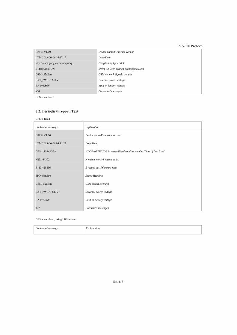
SP7600 Protocol
108 / 117
G79W V1.00
LTM 2013-06-06 14:17:12
http://maps.google.com/maps?q...
ETD:6/ACC ON
GSM -52dBm
EXT_PWR=12.08V
BAT=3.86V
#30
Device name/Firmware version
Date/Time
Google map hyper link
Event ID/User defined event name/Data
GSM network signal strength
External power voltage
Built-in battery voltage
Consumed messages
GPS is not fixed
7.2. Periodical report, Text
GPS is fixed
Content of message Explanation
G79W V1.00
LTM 2013-06-06 09:41:22
GPS 1.55/0.50/3/4
N23.164302
E113.428456
SPD:0km/h 0
GSM -52dBm
EXT_PWR=12.13V
BAT=3.96V
#27
Device name/Firmware version
Date/Time
HDOP/ALTITUDE in meter/Fixed satellite number/Time of first fixed
N means north/S means south
E means east/W means west
Speed/Heading
GSM signal strength
External power voltage
Built-in battery voltage
Consumed messages
GPS is not fixed, using LBS instead
Content of message Explanation
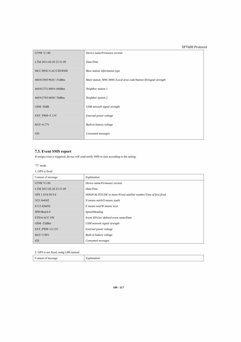
SP7600 Protocol
109 / 117
G79W V1.00
LTM 2013-02-28 23:51:09
MCC/MNC/LAC/CID/RSSI
460/0/2503/962C/-53dBm
460/0/2731/40F4/-60dBm
460/0/2703/4050/-70dBm
GSM -58dB
EXT_PWR=5.13V
BAT=4.17V
#20
Device name/Firmware version
Date/Time
Base station information type
Main station, MNC/MNC/Local area code/Station ID/signal strength
Neighbor station 1
Neighbor station 2
GSM network signal strength
External power voltage
Built-in battery voltage
Consumed messages
7.3. Event SMS report If assign event is triggered, device will send notify SMS to user according to the setting.
“T” mode
1, GPS is fixed
Content of message Explanation
G79W V1.00
LTM 2013-02-28 23:51:09
GPS 1.55/0.50/3/4
N23.164302
E113.428456
SPD:0km/h 0
ETD:6/ACC ON
GSM -52dBm
EXT_PWR=12.13V
BAT=3.96V
#28
Device name/Firmware version
Date/Time
HDOP/ALTITUDE in meter/Fixed satellite number/Time of first fixed
N means north/S means south
E means east/W means west
Speed/Heading
Event ID/User defined event name/Data
GSM network signal strength
External power voltage
Built-in battery voltage
Consumed messages
2. GPS is not fixed, using LBS instead
Content of message Explanation
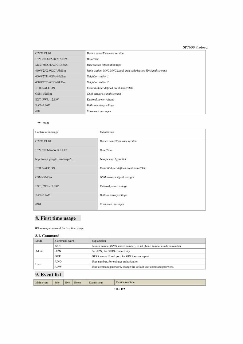
SP7600 Protocol
110 / 117
G79W V1.00
LTM 2013-02-28 23:51:09
MCC/MNC/LAC/CID/RSSI
460/0/2503/962C/-53dBm
460/0/2731/40F4/-60dBm
460/0/2703/4050/-70dBm
ETD:6/ACC ON
GSM -52dBm
EXT_PWR=12.13V
BAT=3.96V
#28
Device name/Firmware version
Date/Time
Base station information type
Main station, MNC/MNC/Local area code/Station ID/signal strength
Neighbor station 1
Neighbor station 2
Event ID/User defined event name/Data
GSM network signal strength
External power voltage
Built-in battery voltage
Consumed messages
“W” mode
Content of message Explanation
G79W V1.00
LTM 2013-06-06 14:17:12
http://maps.google.com/maps?q...
ETD:6/ACC ON
GSM -52dBm
EXT_PWR=12.08V
BAT=3.86V
#301
Device name/Firmware version
Date/Time
Google map hyper link
Event ID/User defined event name/Data
GSM network signal strength
External power voltage
Built-in battery voltage
Consumed messages
8. First time usage
■Necessary command for first time usage.
8.1. Command Mode Command word Explanation
Admin
SSN Admin number (SMS server number), to set phone number as admin number
APN Set APN, for GPRS connectivity
SVR GPRS server IP and port, for GPRS server report
User UNO User number, for end user authorization
UPW User command password, change the default user command password.
9. Event listMain event Sub- Eve Event Event status Device reaction
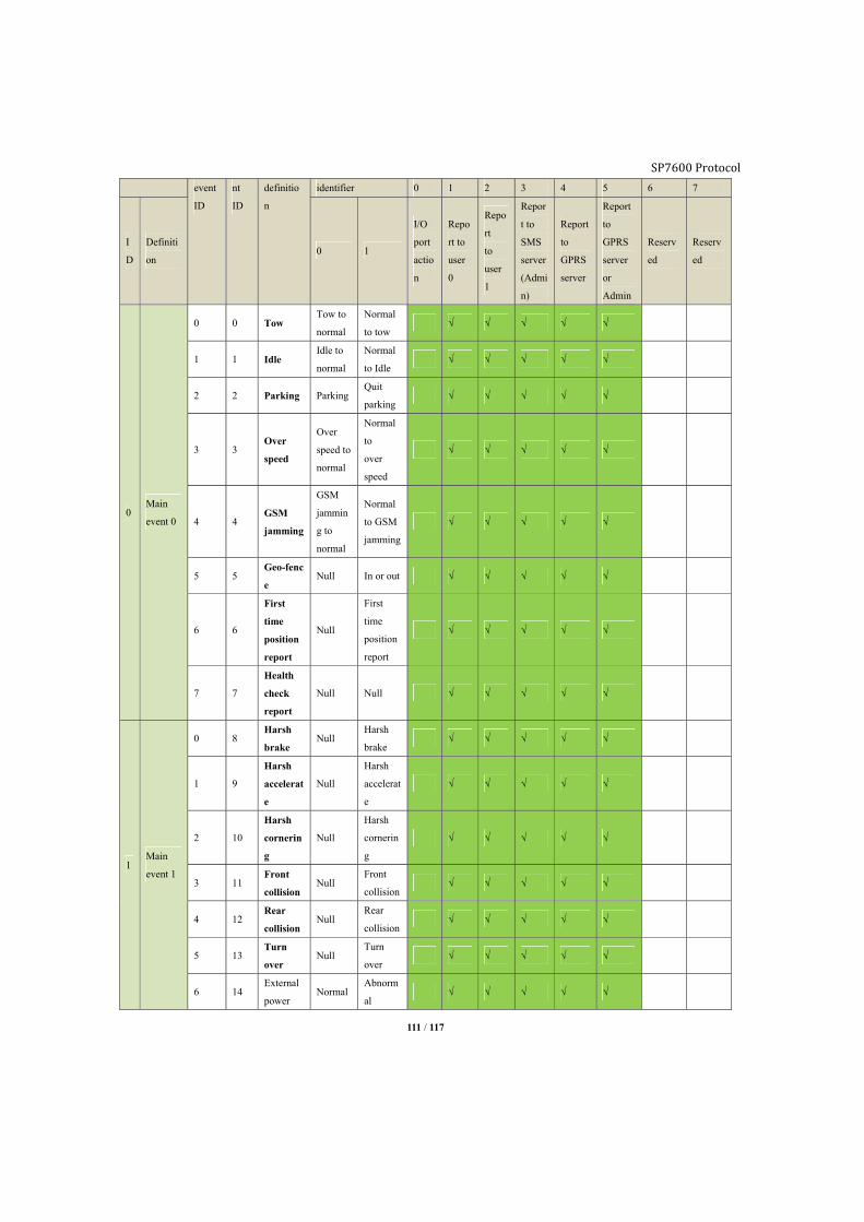
SP7600 Protocol
111 / 117
event
ID
nt
ID
definitio
n
identifier 0 1 2 3 4 5 6 7
I
D
Definiti
on 0 1
I/O
port
actio
n
Repo
rt to
user
0
Repo
rt
to
user
1
Repor
t to
SMS
server
(Admi
n)
Report
to
GPRS
server
Report
to
GPRS
server
or
Admin
Reserv
ed
Reserv
ed
0 Main
event 0
0 0 Tow Tow to
normal
Normal
to tow √ √ √ √ √
1 1 Idle Idle to
normal
Normal
to Idle √ √ √ √ √
2 2 Parking ParkingQuit
parking √ √ √ √ √
3 3 Over
speed
Over
speed to
normal
Normal
to
over
speed
√ √ √ √ √
4 4 GSM
jamming
GSM
jammin
g to
normal
Normal
to GSM
jamming
√ √ √ √ √
5 5 Geo-fenc
e Null In or out √ √ √ √ √
6 6
First
time
position
report
Null
First
time
position
report
√ √ √ √ √
7 7
Health
check
report
Null Null √ √ √ √ √
1 Main
event 1
0 8 Harsh
brake Null
Harsh
brake √ √ √ √ √
1 9
Harsh
accelerat
e
Null
Harsh
accelerat
e
√ √ √ √ √
2 10
Harsh
cornerin
g
Null
Harsh
cornerin
g
√ √ √ √ √
3 11 Front
collision Null
Front
collision √ √ √ √ √
4 12 Rear
collision Null
Rear
collision √ √ √ √ √
5 13 Turn
over Null
Turn
over √ √ √ √ √
6 14 External
power Normal
Abnorm
al √ √ √ √ √

SP7600 Protocol
112 / 117
supply
7 15 Backup
battery Normal
Abnorm
al
2 Main
event 2
0 16
Immobil
izer
status
Connect
ed
Disconn
ected √ √ √ √ √
1 17 Tag
event Leaving Entering √ √ √ √ √
2 18 RF
pairing Paired
No
paired √ √ √ √ √
3 19 Tag low
voltage No Yes √ √ √ √ √
4 20 OBDII
DTC No Yes √ √ √ √ √
5 21 Over
revving No Yes √ √ √ √ √
6 22 Engine
over heat No Yes √ √ √ √ √
7 23 Service
mileage No Yes √ √ √ √ √
3 Main
event 3
0 24 Engine
oil No Yes √ √ √ √ √
1 25 Tire No Yes √ √ √ √ √
2 26 ACC OFF ON √ √ √ √ √
3 27 Balance
notice Null Yes √ √ √ √ √
4 28 J1939
DTC No Yes √ √ √ √ √
5 29
Reserved
Enterings
leeping
mode
with low
voltage
battery
Reserve
dNo.
Reserve
dEnterin
g
√ √ √ √ √
6 30 Reserved Reserve
d
Reserve
d
7 31 Reserved Reserve
d
Reserve
d
4 … ……Reserv
ed … …
5 … … … … …
6 … … … … …
7 Main
event 7
Comb
0 56 √ √ √ √ √
Comb 57 √ √ √ √ √
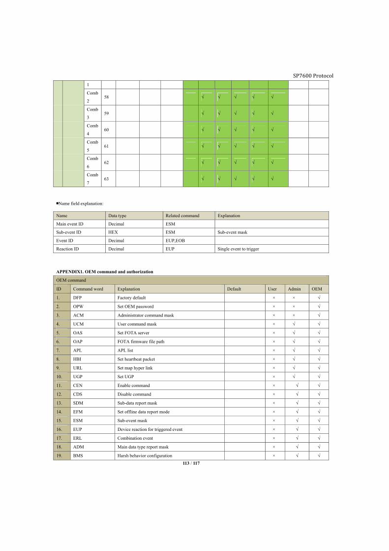
SP7600 Protocol
113 / 117
1
Comb
2 58 √ √ √ √ √
Comb
3 59 √ √ √ √ √
Comb
4 60 √ √ √ √ √
Comb
5 61 √ √ √ √ √
Comb
6 62 √ √ √ √ √
Comb
7 63 √ √ √ √ √
■Name field explanation:
Name Data type Related command Explanation
Main event ID Decimal ESM
Sub-event ID HEX ESM Sub-event mask
Event ID Decimal EUP,EOB
Reaction ID Decimal EUP Single event to trigger
APPENDIX1. OEM command and authorization
OEM command
ID Command word Explanation Default User Admin OEM
1. DFP Factory default × × √
2. OPW Set OEM password × × √
3. ACM Administrator command mask × × √
4. UCM User command mask × √ √
5. OAS Set FOTA server × √ √
6. OAP FOTA firmware file path × √ √
7. APL APL list × √ √
8. HBI Set heartbeat packet × √ √
9. URL Set map hyper link × √ √
10. UGP Set UGP × √ √
11. CEN Enable command × √ √
12. CDS Disable command × √ √
13. SDM Sub-data report mask × √ √
14. EFM Set offline data report mode × √ √
15. ESM Sub-event mask × √ √
16. EUP Device reaction for triggered event × √ √
17. ERL Combination event × √ √
18. ADM Main data type report mask × √ √
19. BMS Harsh behavior configuration × √ √
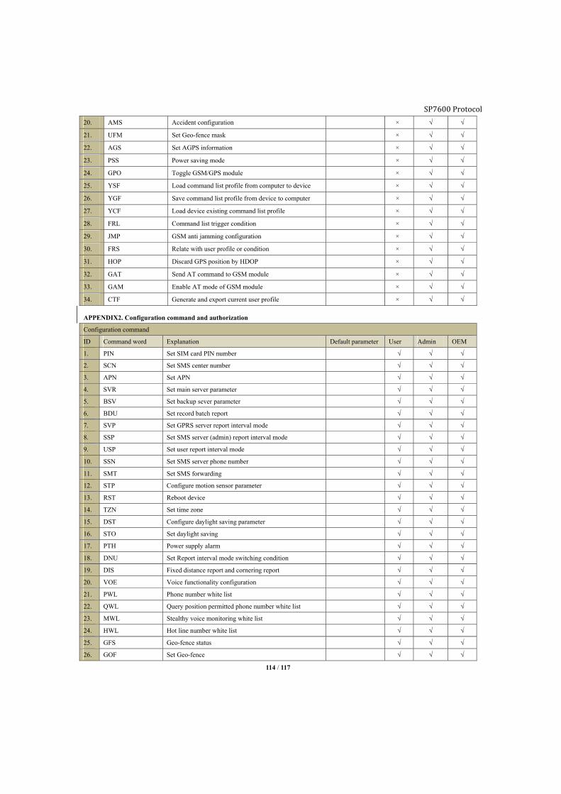
SP7600 Protocol
114 / 117
20. AMS Accident configuration × √ √
21. UFM Set Geo-fence mask × √ √
22. AGS Set AGPS information × √ √
23. PSS Power saving mode × √ √
24. GPO Toggle GSM/GPS module × √ √
25. YSF Load command list profile from computer to device × √ √
26. YGF Save command list profile from device to computer × √ √
27. YCF Load device existing command list profile × √ √
28. FRL Command list trigger condition × √ √
29. JMP GSM anti jamming configuration × √ √
30. FRS Relate with user profile or condition × √ √
31. HOP Discard GPS position by HDOP × √ √
32. GAT Send AT command to GSM module × √ √
33. GAM Enable AT mode of GSM module × √ √
34. CTF Generate and export current user profile × √ √
APPENDIX2. Configuration command and authorization
Configuration command
ID Command word Explanation Default parameter User Admin OEM
1. PIN Set SIM card PIN number √ √ √
2. SCN Set SMS center number √ √ √
3. APN Set APN √ √ √
4. SVR Set main server parameter √ √ √
5. BSV Set backup sever parameter √ √ √
6. BDU Set record batch report √ √ √
7. SVP Set GPRS server report interval mode √ √ √
8. SSP Set SMS server (admin) report interval mode √ √ √
9. USP Set user report interval mode √ √ √
10. SSN Set SMS server phone number √ √ √
11. SMT Set SMS forwarding √ √ √
12. STP Configure motion sensor parameter √ √ √
13. RST Reboot device √ √ √
14. TZN Set time zone √ √ √
15. DST Configure daylight saving parameter √ √ √
16. STO Set daylight saving √ √ √
17. PTH Power supply alarm √ √ √
18. DNU Set Report interval mode switching condition √ √ √
19. DIS Fixed distance report and cornering report √ √ √
20. VOE Voice functionality configuration √ √ √
21. PWL Phone number white list √ √ √
22. QWL Query position permitted phone number white list √ √ √
23. MWL Stealthy voice monitoring white list √ √ √
24. HWL Hot line number white list √ √ √
25. GFS Geo-fence status √ √ √
26. GOF Set Geo-fence √ √ √
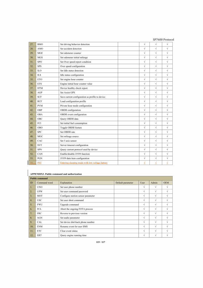
SP7600 Protocol
115 / 117
27. BMO Set driving behavior detection √ √ √
28. AMO Set accident detection √ √ √
29. MGE Set odometer counter √ √ √
30. MGS Set odometer initial mileage √ √ √
31. SPO Set Over speed report condition √ √ √
32. SPS Over speed configuration √ √ √
33. ILO Set Idle status detection √ √ √
34. ILS Idle status configuration √ √ √
35. ETO Set engine hour counter √ √ √
36. ETS Engine initial hour counter value √ √ √
37. HTM Device healthy check report √ √ √
38. AGP Set Assist GPS √ √ √
39. SCF Save current configuration as profile to device √ √ √
40. RCF Load configuration profile √ √ √
41. PVM Private hour mode configuration √ √ √
42. OBP OBDII configuration √ √ √
43. OBA OBDII event configuration √ √ √
44. OBC Query OBDII data √ √ √
45. FCI Set initial fuel consumption √ √ √
46. OBO Toggle OBDII feature √ √ √
47. SPC Set OBDII rate √ √ √
48. MGC Set mileage source √ √ √
49. CAC Set 3 axis sensor √ √ √
50. SVT Server timeout configuration √ √ √
51. SPN Query current protocol used by device √ √ √
52. CAN Enable/disable J1939 function √ √ √
53. PGN J1939 data item configuration √ √ √
54. PST Entering sleeping mode with low voltage battery √ √ √
APPENDIX3. Public command and authorization
Public command
ID Command word Explanation Default parameter User Admin OEM
1. UNO Set user phone number √ √ √
2. UPW Set user command password √ √ √
3. MOT Configure motion sensor parameter √ √ √
4. USC Set user short command √ √ √
5. FWU Upgrade command √ √ √
6. FCL Abort the ongoing FOTA process √ √ √
7. FRC Reverse to previous version √ √ √
8. AGN Set audio parameter √ √ √
9. CAL Set device dial-back phone number √ √ √
10. ENM Rename event for user SMS √ √ √
11. ETC Clear event status √ √ √
12. ERT Query engine running time √ √ √

SP7600 Protocol
116 / 117
13. PRQ Query current position √ √ √
14. TIM Query current GMT time √ √ √
15. NAM Query product name √ √ √
16. VER Query device hardware/software version √ √ √
17. MEI Query IMEI number √ √ √
18. MSI Query IMSI of SIM card √ √ √
19. CID Query CCID of SIM card √ √ √
20. CSQ Query GSM signal strength √ √ √
21. REG Query GSM registration status √ √ √
22. SCC Clear SMS counter √ √ √
23. SCR Query SMS counter √ √ √
24. GSM Query GSM information √ √ √
25. GPS Query GPS information √ √ √
26. ADC Query ADC information √ √ √
27. GFT Query GFT information √ √ √
28. STT Query device status √ √ √
29. GTT Query Geo-fence status √ √ √
30. MGR Query mileage √ √ √
31. ETT Query event status bit √ √ √
32. JAM Enable anti-jamming feature √ √ √
33. TOW Enable Tow detection feature √ √ √
34. CFN Query current configuration profile number √ √ √
35. PTY Query device model √ √ √
36. IMM Toggle immobilizer √ √ √
37. MAT Pairing mode and wireless query √ √ √
38. WPS Configure immobilizer √ √ √
39. TNM Set driver name √ √ √
40. OBS Query OBDII status √ √ √
41. OBD Request OBDII data report √ √ √
42. FUL Query fuel consumption √ √ √
43. FUC Query fuel consumption √ √ √
44. CHC Query licensed status √ √ √
45. GFC Reset Geo fence √ √ √
46. EUC Reset all events action √ √ √
47. BLS Balance notification √ √ √
48. TSP Define separator in USSD √ √ √
49. SIM Query current SIM card number √ √ √
50. BUZ Enable buzzer √ √ √
51. GVR Query GSM module an version √ √ √
52. RPD Set some parameters to factory default √ √ √
53. EGT Set duration threshold for detect ACC status √ √ √
54. MCM Query mileage source √ √ √
55. GCD Query Real-time J1939 Data √ √ √
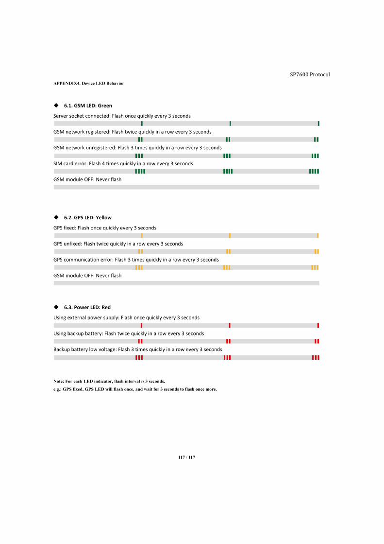
117 / 117
APPENDIX4. Device LED Behavior
6.1. GSM LED: Green
Server socket connected: Flash once quickly every 3 seconds
GSM network registered: Flash twice quickly in a row every 3 seconds
GSM network unregistered: Flash 3 times quickly in a row every 3 seconds
SIM card error: Flash 4 times quickly in a row every 3 seconds
GSM module OFF: Never flash
6.2. GPS LED: Yellow
GPS fixed: Flash once quickly every 3 seconds
GPS unfixed: Flash twice quickly in a row every 3 seconds
GPS communication error: Flash 3 times quickly in a row every 3 seconds
GSM module OFF: Never flash
6.3. Power LED: Red
Using external power supply: Flash once quickly every 3 seconds
Using backup battery: Flash twice quickly in a row every 3 seconds
Backup battery low voltage: Flash 3 times quickly in a row every 3 seconds
Note: For each LED indicator, flash interval is 3 seconds.
e.g.: GPS fixed, GPS LED will flash once, and wait for 3 seconds to flash once more.
SP7600 Protocol


![Apps Framework API[V1.10]](https://img.dokumen.tips/doc/110x75/55400cb64a7959251a8b49d2/apps-framework-apiv110.jpg)


