Embed Size (px)
Citation preview
w w w . a u t o s t e e l . o r g
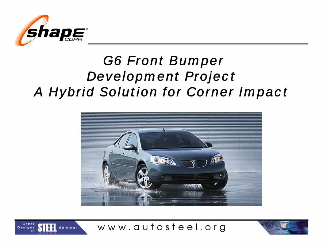
G6 Front Bumper Development Project
A Hybrid Solution for Corner Impact
Michael HallShape Corporation
Company Logo

w w w . a u t o s t e e l . o r g
Brief Introduction to Shape
• World leader in automotive and industrial products manufacturing
• Founded in 1974• Over 1100 employees and 5
plants• Headquarters in Grand
Haven, Michigan• Global presence
– Sales offices in: • Madison Heights, Michigan • Tokyo, Japan• Frankfurt, Germany
• Headquartered in Grand Haven, Michigan
– Sales offices• Frankfurt, Germany• Tokyo, Japan• Madison Heights, Michigan
Ship to Locations

w w w . a u t o s t e e l . o r g
Shape Automotive Products

w w w . a u t o s t e e l . o r g
Shape Customers
• GM• Herman Miller • Toyota• Allsteel • Mitsubishi • Ford • Mazda • DaimlerChrysler• Case• Tower • Nissan
•Whirlpool •Xerox •Dana •Honda •Orion •Hart & Cooley •Subaru •Trendway•Valeo•Calsonic•Metalsa
Shape is proud to be the selected supplier to all of these fine companies and many others

w w w . a u t o s t e e l . o r g
Over 80 rollform lines in operation
Manufacturing Excellence
• Roll forming• Stamping• Welding• Injection molding• E-Coating• Assembly

w w w . a u t o s t e e l . o r g
Engineering and Design
•CATIA•AutoCAD•TogoCAD•Unigraphics•SDRC•IGES•3D Modeling•C3P•IDEAS•Solid Works•Pro Engineer
Design CAE•LSDYNA 3D•Hyperview
Dynamic Testing•IIHS•CMVSS

w w w . a u t o s t e e l . o r g
Company Logo G6 Front Design Challenges
Design Challenges:•Malibu front bumper was intended to be carry over for G6•Insufficient space available between the G6 fascia and end of beam to provide adequate energy absorption and fascia protection for corner impacts. The fascia design cut through the end of the beam•Two typical countermeasures to create more space:
1. Mitre cut & cap end of beam2. End-form beam “crush and tuck”
•Secondary operations are expensive, produce waste, and can require additional capital investment

w w w . a u t o s t e e l . o r g
Malibu and G6 ComparisonMalibu Front Bumper G6 Fascia and Bumper

w w w . a u t o s t e e l . o r g
Design Constraints
• Only 65 mm packaging space was allowed at the bumper corner due to the fascia styling change
• The Malibu bumper intended for use on the G6 is 70mm deep fore-aft at the bumper corner, which violated the available packaging space and left no room for an energy absorber (EA)
• The initial intrusion target for 5MPH corner impact was 45mm with 65kN per rail load capabilities
• High speed impact and modal analysis demands the UHSS (DP965) beam continue to span the rails cross-car

w w w . a u t o s t e e l . o r g
Development Plan
• Experiment with various means of reducing UHSS bumper section depth at the ends to accommodate the G6 fascia
• Experiment with energy absorber technologies that work in conjunction with UHSS bumpers to improve IIHS corner barrier performance
• Run dynamic impacts on sub-system level to attain design direction
• Final vehicle weight was not known at development stage, so the Malibu vehicle mass of 3200 Lbs was used for testing purposes

w w w . a u t o s t e e l . o r g
Bumper End Concepts
• “Crush & Tuck”– Means of reducing
section depth by pre-setting beam using steel die tooling
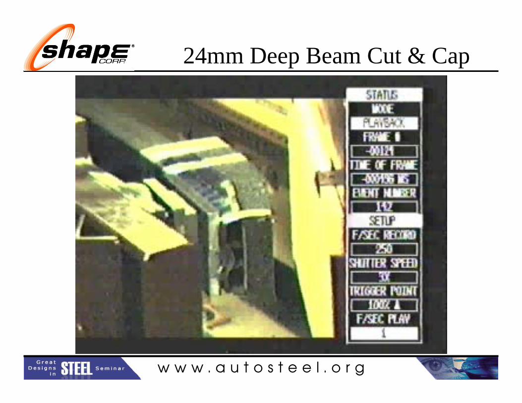
• “Cut & Cap”– Mitre cut an angle on the
end of the beam and weld on a stamped UHSS cap

w w w . a u t o s t e e l . o r g
Energy Absorber Technologies
• EPP Foam – Easy to prototype and test. EPP foam was selected for
initial dynamic crash testing experiments in conjunction with end treatments.
• Injection Molded PC/PBT Energy Absorber– Higher efficiency in crash performance. Injection molded
PC/PBT was ultimately selected for this application due to the efficiency in conjunction with UHSS bumper section.

w w w . a u t o s t e e l . o r g
Dynamic Test Plan
• Experiment with the following end configurations:– A) “Crush & Tuck” at (4) different depths– B) “Cut & Cap” at (3) different depths– C) Cut the beam short and wrap the ends with Injection Molded EA
• Run 5MPH 30 degree corner barrier impact crash tests
• Document load vs. displacement results for all dynamic Impacts

w w w . a u t o s t e e l . o r g
40mm deep beam Crush & Tuck

w w w . a u t o s t e e l . o r g
45mm Deep Beam Crush & Tuck

w w w . a u t o s t e e l . o r g
50mm Deep Beam Crush & Tuck

w w w . a u t o s t e e l . o r g
60mm Deep Beam Crush & Tuck

w w w . a u t o s t e e l . o r g
Crush & Tuck SummaryG M X 3 8 1 F r o n t B u m p e r
I I H S 3 0 ° F i x e d B a r r i e r I m p a c t @ 5 m p hE n d F o r m e d B e a m s
T o t a l B e a m / E A P a c k a g e H e i g h t o f 6 5 m m @ C o r n e rV e h i c l e W e i g h t = 3 2 0 0 l b s . , 6 . 6 p c f E n e r g y A b s o r b e r
S y s t e m S t r o k e ( m m )0 5 1 0 1 5 2 0 2 5 3 0 3 5 4 0 4 5 5 0 5 5 6 0
Tota
l Loa
d (k
N)
0
1 0
2 0
3 0
4 0
5 0
6 0
7 0
8 0
9 0
1 0 0
E n d F o r m D e s i g n # 1 - 4 0 m m o f b e a m h e i g h t f o r e - aE n d F o r m D e s i g n # 2 - 4 5 m m o f b e a m h e i g h t f o r e - aE n d F o r m D e s i g n # 3 - 5 0 m m o f b e a m h e i g h t f o r e - aE n d F o r m D e s i g n # 4 - 6 0 m m o f b e a m h e i g h t f o r e - a
w w w . a u t o s t e e l . o r g
24mm Deep Beam Cut & Cap

w w w . a u t o s t e e l . o r g
40mm Deep Beam Cut & Cap

w w w . a u t o s t e e l . o r g
60mm Deep Beam Cut & Cap

w w w . a u t o s t e e l . o r g
Cut & Cap Summary
S y s t e m S t r o k e ( m m )0 5 1 0 1 5 2 0 2 5 3 0 3 5 4 0 4 5 5 0 5 5 6 0
Tota
l Loa
d (k
N)
0
1 0
2 0
3 0
4 0
5 0
6 0
7 0
8 0
9 0
1 0 0
C u t & C a p D e s i g n # 1 - 2 4 m m o f m a t e r i a l f o r e - a f tC u t & C a p D e s i g n # 2 - 4 0 m m o f m a t e r i a l f o r e - a f tC u t & C a p D e s i g n # 3 - 6 5 m m o f m a t e r i a l f o r e - a f t
G M X 3 8 1 F r o n t B u m p e rI I H S 3 0 ° F i x e d B a r r i e r I m p a c t @ 5 m p h
B e a m s C u t & C a p p e dT o t a l B e a m / E A P a c k a g e H e i g h t o f 6 5 m m @ C o r n e rV e h i c l e W e i g h t = 3 2 0 0 l b s . , 6 . 6 p c f E n e r g y A b s o r b e r

w w w . a u t o s t e e l . o r g
Injection Molded EA Solution
• Shorten the beam crosscar (Y) and allow Injection molded EA to fill packaging space at ends
• Beam still spans the rails for modal and high speed load transfer
• Crush cone forward of the rail bracket reacts against the rails and the beam ends during 30 degree impact
Malibu Front G6 Front
G6 Front withInjection MoldedEA

w w w . a u t o s t e e l . o r g
Concept: Eliminates the “cut and cap”and weld operations or the crush and tuck” and replace EPP EA with a NetShape injection molded EA.
• Reduced absorber cost ( $1.00 to $3.00 anticipated)• Improved corner impact performance• Reduced mass and cost of impact bar ( ~ 1.00 lb and $1-3 savings potential)• Elimination of Mitre-cutting equipment cost• The ability to translate savings and performance enhancements on other vehicles (Common beam strategy)
Injection Molded EA SolutionInjection Molded EA Solution
Anticipated advantages

w w w . a u t o s t e e l . o r g
Injection Molded EA Impact

w w w . a u t o s t e e l . o r g
Load vs. Displacement Molded EA

w w w . a u t o s t e e l . o r g
Final Design AdvantagesFinal Design Advantages
Shape/NetShape Solution•$1.64 saved per part (Beam Only)•$2.00 saved on the EA•$3.64 total savings on piece cost•$1,025,000 in annual savings vs. Malibu Front Beam•$450,000 saved in secondary tooling•Enhanced corner impact performance•Enabled styling requirements of the G6•Mass savings of 0.22lbs vs. Malibu Front bumper system

w w w . a u t o s t e e l . o r g
Additional Advantages
• Steel beam assembly is produced using GMX 380 production tooling which contributed to the tooling investment cost savings
• Injection Molded PC/PBT energy absorber supplied as POA to fascia
• Injection Molded EA provides additional fascia support under headlamps compared to EPP foam solution
• Higher dimensional stability of injection molded product improves gap condition to the fascia

w w w . a u t o s t e e l . o r g
Final IIHS Repair Estimate
• IIHS total corner damage limited to $592• IIHS damage includes
– Replacing the EA– Repair only of bumper – Repair only of fascia– Re-aiming headlamps– Labor and touch up paint