Embed Size (px)
Citation preview

G5 5090Service Manual
Regulatory Model: D28MRegulatory Type: D28M002
May 2020Rev. A01
Notes, cautions, and warnings
NOTE: A NOTE indicates important information that helps you make better use of your product.
CAUTION: A CAUTION indicates either potential damage to hardware or loss of data and tells you how to avoid the
problem.
WARNING: A WARNING indicates a potential for property damage, personal injury, or death.
© 2019-2020 Dell Inc. or its subsidiaries. All rights reserved. Dell, EMC, and other trademarks are trademarks of Dell Inc. or itssubsidiaries. Other trademarks may be trademarks of their respective owners.

1 Working inside your computer....................................................................................................... 6Safety instructions.................................................................................................................................................................6Before working inside your computer................................................................................................................................. 6
Before you begin .............................................................................................................................................................6Electrostatic discharge—ESD protection.......................................................................................................................... 7ESD field service kit ..............................................................................................................................................................7Transporting sensitive components.................................................................................................................................... 8After working inside your computer....................................................................................................................................8
2 Removing and installing components............................................................................................. 9Inside view of your computer...............................................................................................................................................9System-board components................................................................................................................................................ 10Recommended tools............................................................................................................................................................. 11Screw list................................................................................................................................................................................11Left-side cover..................................................................................................................................................................... 12
Removing the left-side cover....................................................................................................................................... 12Installing the left-side cover.......................................................................................................................................... 12
Light bar................................................................................................................................................................................ 13Removing the light bar...................................................................................................................................................13Installing the light bar..................................................................................................................................................... 14
Front cover........................................................................................................................................................................... 15Removing the front cover............................................................................................................................................. 15Installing the front cover............................................................................................................................................... 16
2.5-inch hard drive............................................................................................................................................................... 17Removing the 2.5-inch hard drive................................................................................................................................ 17Installing the 2.5-inch hard drive.................................................................................................................................. 19
3.5-inch hard drive.............................................................................................................................................................. 20Removing the 3.5-inch hard drive...............................................................................................................................20Installing the 3.5-inch hard drive................................................................................................................................. 22
Chassis fan........................................................................................................................................................................... 23Removing the chassis fan.............................................................................................................................................23Installing the chassis fan............................................................................................................................................... 23
Memory modules................................................................................................................................................................. 25Removing the memory modules.................................................................................................................................. 25Installing the memory modules.....................................................................................................................................26
Wireless card........................................................................................................................................................................ 27Removing the wireless card......................................................................................................................................... 27Installing the wireless card............................................................................................................................................28
Solid-state drive/Intel Optane...........................................................................................................................................30Removing the solid-state drive/Intel Optane............................................................................................................ 30Installing the solid-state drive/Intel Optane................................................................................................................31
Graphics card....................................................................................................................................................................... 33Removing the graphics card........................................................................................................................................ 33Installing the graphics card...........................................................................................................................................34
Contents
Contents 3

Coin-cell battery.................................................................................................................................................................. 35Removing the coin-cell battery....................................................................................................................................35Installing the coin-cell battery...................................................................................................................................... 36
Power-supply unit............................................................................................................................................................... 36Removing the power-supply unit.................................................................................................................................36Installing the power-supply unit................................................................................................................................... 38
Processor fan and heat-sink assembly..............................................................................................................................41Removing the processor fan and heat-sink assembly............................................................................................... 41Installing the processor fan and heat-sink assembly.................................................................................................42
Processor..............................................................................................................................................................................43Removing the processor...............................................................................................................................................43Installing the processor................................................................................................................................................. 44
VR heat sink......................................................................................................................................................................... 45Removing the VR heat sink..........................................................................................................................................45Installing the VR heat sink............................................................................................................................................ 46
LED daughter board............................................................................................................................................................ 47Removing the LED daughter board.............................................................................................................................47Installing the LED daughter board............................................................................................................................... 48
System board.......................................................................................................................................................................49Removing the system board........................................................................................................................................ 49Installing the system board...........................................................................................................................................52
3 Device drivers............................................................................................................................ 57Operating system................................................................................................................................................................ 57Downloading the audio driver.............................................................................................................................................57Downloading the graphics driver....................................................................................................................................... 57Downloading the USB driver..............................................................................................................................................58Downloading the WiFi driver.............................................................................................................................................. 58Downloading the chipset driver.........................................................................................................................................59Downloading the network driver....................................................................................................................................... 59
4 System setup............................................................................................................................. 61System setup........................................................................................................................................................................61BIOS overview......................................................................................................................................................................61Entering BIOS setup program.............................................................................................................................................61Navigation keys.................................................................................................................................................................... 61Boot Sequence..................................................................................................................................................................... 61System setup options......................................................................................................................................................... 62System and setup password.............................................................................................................................................. 67
Assigning a system setup password........................................................................................................................... 68Deleting or changing an existing system setup password........................................................................................68Clearing CMOS settings............................................................................................................................................... 68Clearing BIOS (System Setup) and System passwords...........................................................................................69
5 Troubleshooting..........................................................................................................................71Enhanced Pre-Boot System Assessment (ePSA) diagnostics.......................................................................................71
Running the ePSA diagnostics......................................................................................................................................71Diagnostics............................................................................................................................................................................ 71
System diagnostic lights............................................................................................................................................... 73
4 Contents

Diagnostic error messages................................................................................................................................................. 74System error messages...................................................................................................................................................... 76Recovering the operating system......................................................................................................................................77Flashing BIOS (USB key).................................................................................................................................................... 77Flashing the BIOS................................................................................................................................................................ 77WiFi power cycle..................................................................................................................................................................78Flea power release...............................................................................................................................................................78Enabling Intel Optane memory...........................................................................................................................................78Disabling Intel Optane memory.......................................................................................................................................... 79
6 Getting help and contacting Dell..................................................................................................80
Contents 5

Working inside your computer
Safety instructionsUse the following safety guidelines to protect your computer from potential damage and to ensure your personal safety. Unless otherwisenoted, each procedure included in this document assumes that you have read the safety information that shipped with your computer.
NOTE: Before working inside your computer, read the safety information that shipped with your computer. For more
safety best practices, see the Regulatory Compliance home page at www.dell.com/regulatory_compliance.
NOTE: Disconnect all power sources before opening the computer cover or panels. After you finish working inside the
computer, replace all covers, panels, and screws before connecting to the electrical outlet.
CAUTION: To avoid damaging the computer, ensure that the work surface is flat and clean.
CAUTION: Handle components and cards with care. Do not touch the components or contacts on a card. Hold a card by
its edges or by its metal mounting bracket. Hold a component such as a processor by its edges, not by its pins.
CAUTION: You should only perform troubleshooting and repairs as authorized or directed by the Dell technical
assistance team. Damage due to servicing that is not authorized by Dell is not covered by your warranty. See the safety
instructions that shipped with the product or at www.dell.com/regulatory_compliance.
CAUTION: Before touching anything inside your computer, ground yourself by using a wrist grounding strap or by
periodically touching an unpainted metal surface, such as the metal at the back of the computer. While you work,
periodically touch an unpainted metal surface to dissipate static electricity, which could harm internal components.
CAUTION: When you disconnect a cable, pull on its connector or on its pull tab, not on the cable itself. Some cables have
connectors with locking tabs or thumb-screws that you must disengage before disconnecting the cable. When
disconnecting cables, keep them evenly aligned to avoid bending any connector pins. When connecting cables, ensure
that the ports and connectors are correctly oriented and aligned.
CAUTION: Press and eject any installed card from the media-card reader.
NOTE: The color of your computer and certain components may appear differently than shown in this document.
Before working inside your computerNOTE: The images in this document may differ from your computer depending on the configuration you ordered.
Before you begin
Steps
1. Save and close all open files and exit all open applications.
2. Shut down your computer. Click Start > Power > Shut down.
NOTE: If you are using a different operating system, see the documentation of your operating system for shut-down
instructions.
3. Disconnect your computer and all attached devices from their electrical outlets.4. Disconnect all attached network devices and peripherals, such as keyboard, mouse, and monitor from your computer.5. Remove any media card and optical disc from your computer, if applicable.
1
6 Working inside your computer

Electrostatic discharge—ESD protectionESD is a major concern when you handle electronic components, especially sensitive components such as expansion cards, processors,memory DIMMs, and system boards. Very slight charges can damage circuits in ways that may not be obvious, such as intermittentproblems or a shortened product life span. As the industry pushes for lower power requirements and increased density, ESD protection isan increasing concern.
Due to the increased density of semiconductors used in recent Dell products, the sensitivity to static damage is now higher than inprevious Dell products. For this reason, some previously approved methods of handling parts are no longer applicable.
Two recognized types of ESD damage are catastrophic and intermittent failures.
• Catastrophic – Catastrophic failures represent approximately 20 percent of ESD-related failures. The damage causes an immediateand complete loss of device functionality. An example of catastrophic failure is a memory DIMM that has received a static shock andimmediately generates a "No POST/No Video" symptom with a beep code emitted for missing or nonfunctional memory.
• Intermittent – Intermittent failures represent approximately 80 percent of ESD-related failures. The high rate of intermittent failuresmeans that most of the time when damage occurs, it is not immediately recognizable. The DIMM receives a static shock, but thetracing is merely weakened and does not immediately produce outward symptoms related to the damage. The weakened trace maytake weeks or months to melt, and in the meantime may cause degradation of memory integrity, intermittent memory errors, etc.
The more difficult type of damage to recognize and troubleshoot is the intermittent (also called latent or "walking wounded") failure.
Perform the following steps to prevent ESD damage:
• Use a wired ESD wrist strap that is properly grounded. The use of wireless anti-static straps is no longer allowed; they do not provideadequate protection. Touching the chassis before handling parts does not ensure adequate ESD protection on parts with increasedsensitivity to ESD damage.
• Handle all static-sensitive components in a static-safe area. If possible, use anti-static floor pads and workbench pads.• When unpacking a static-sensitive component from its shipping carton, do not remove the component from the anti-static packing
material until you are ready to install the component. Before unwrapping the anti-static packaging, ensure that you discharge staticelectricity from your body.
• Before transporting a static-sensitive component, place it in an anti-static container or packaging.
ESD field service kitThe unmonitored Field Service kit is the most commonly used service kit. Each Field Service kit includes three main components: anti-static mat, wrist strap, and bonding wire.
Components of an ESD field service kitThe components of an ESD field service kit are:
• Anti-Static Mat – The anti-static mat is dissipative and parts can be placed on it during service procedures. When using an anti-static mat, your wrist strap should be snug and the bonding wire should be connected to the mat and to any bare metal on the systembeing worked on. Once deployed properly, service parts can be removed from the ESD bag and placed directly on the mat. ESD-sensitive items are safe in your hand, on the ESD mat, in the system, or inside a bag.
• Wrist Strap and Bonding Wire – The wrist strap and bonding wire can be either directly connected between your wrist and baremetal on the hardware if the ESD mat is not required, or connected to the anti-static mat to protect hardware that is temporarilyplaced on the mat. The physical connection of the wrist strap and bonding wire between your skin, the ESD mat, and the hardware isknown as bonding. Use only Field Service kits with a wrist strap, mat, and bonding wire. Never use wireless wrist straps. Always beaware that the internal wires of a wrist strap are prone to damage from normal wear and tear, and must be checked regularly with awrist strap tester in order to avoid accidental ESD hardware damage. It is recommended to test the wrist strap and bonding wire atleast once per week.
• ESD Wrist Strap Tester – The wires inside of an ESD strap are prone to damage over time. When using an unmonitored kit, it is abest practice to regularly test the strap prior to each service call, and at a minimum, test once per week. A wrist strap tester is thebest method for doing this test. If you do not have your own wrist strap tester, check with your regional office to find out if they haveone. To perform the test, plug the wrist-strap's bonding-wire into the tester while it is strapped to your wrist and push the button totest. A green LED is lit if the test is successful; a red LED is lit and an alarm sounds if the test fails.
• Insulator Elements – It is critical to keep ESD sensitive devices, such as plastic heat sink casings, away from internal parts that areinsulators and often highly charged.
• Working Environment – Before deploying the ESD Field Service kit, assess the situation at the customer location. For example,deploying the kit for a server environment is different than for a desktop or portable environment. Servers are typically installed in arack within a data center; desktops or portables are typically placed on office desks or cubicles. Always look for a large open flat workarea that is free of clutter and large enough to deploy the ESD kit with additional space to accommodate the type of system that is
Working inside your computer 7
being repaired. The workspace should also be free of insulators that can cause an ESD event. On the work area, insulators such asStyrofoam and other plastics should always be moved at least 12 inches or 30 centimeters away from sensitive parts before physicallyhandling any hardware components
• ESD Packaging – All ESD-sensitive devices must be shipped and received in static-safe packaging. Metal, static-shielded bags arepreferred. However, you should always return the damaged part using the same ESD bag and packaging that the new part arrived in.The ESD bag should be folded over and taped shut and all the same foam packing material should be used in the original box that thenew part arrived in. ESD-sensitive devices should be removed from packaging only at an ESD-protected work surface, and partsshould never be placed on top of the ESD bag because only the inside of the bag is shielded. Always place parts in your hand, on theESD mat, in the system, or inside an anti-static bag.
• Transporting Sensitive Components – When transporting ESD sensitive components such as replacement parts or parts to bereturned to Dell, it is critical to place these parts in anti-static bags for safe transport.
ESD protection summaryIt is recommended that all field service technicians use the traditional wired ESD grounding wrist strap and protective anti-static mat at alltimes when servicing Dell products. In addition, it is critical that technicians keep sensitive parts separate from all insulator parts whileperforming service and that they use anti-static bags for transporting sensitive components.
Transporting sensitive componentsWhen transporting ESD sensitive components such as replacement parts or parts to be returned to Dell, it is critical to place these parts inanti-static bags for safe transport.
Lifting equipmentAdhere to the following guidelines when lifting heavy weight equipment:
CAUTION: Do not lift greater than 50 pounds. Always obtain additional resources or use a mechanical lifting device.
1. Get a firm balanced footing. Keep your feet apart for a stable base, and point your toes out.2. Tighten stomach muscles. Abdominal muscles support your spine when you lift, offsetting the force of the load.3. Lift with your legs, not your back.4. Keep the load close. The closer it is to your spine, the less force it exerts on your back.5. Keep your back upright, whether lifting or setting down the load. Do not add the weight of your body to the load. Avoid twisting your
body and back.6. Follow the same techniques in reverse to set the load down.
After working inside your computerAbout this task
CAUTION: Leaving stray or loose screws inside your computer may severely damage your computer.
Steps
1. Replace all screws and ensure that no stray screws remain inside your computer.2. Connect any external devices, peripherals, or cables you removed before working on your computer.3. Replace any media cards, discs, or any other parts that you removed before working on your computer.4. Connect your computer and all attached devices to their electrical outlets.5. Turn on your computer.
8 Working inside your computer

Removing and installing components
Inside view of your computerNOTE: The appearance of heat sink differs depending on the graphics configuration you ordered.
Figure 1. Inside view of your computer
1. 3.5-inch hard drive assembly2. front cover3. graphics card4. power-supply unit5. PCIE door6. processor fan and heat-sink assembly7. 2.5-inch hard-drive assembly8. light bar
2
Removing and installing components 9
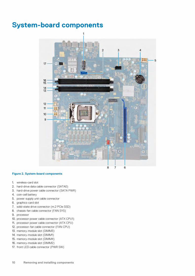
System-board components
Figure 2. System-board components
1. wireless-card slot2. hard-drive data cable connector (SATA0)3. hard-drive power cable connector (SATA PWR)4. coin-cell battery5. power-supply unit cable connector6. graphics-card slot7. solid-state drive connector (m.2 PCIe SSD)8. chassis-fan cable connector (FAN SYS)9. processor10. processor power cable connector (ATX CPU1)11. processor power cable connector (ATX CPU)12. processor-fan cable connector (FAN CPU)13. memory-module slot (DIMM3)14. memory-module slot (DIMM1)15. memory-module slot (DIMM4)16. memory-module slot (DIMM2)17. front LED cable connector (PWR SW)
10 Removing and installing components
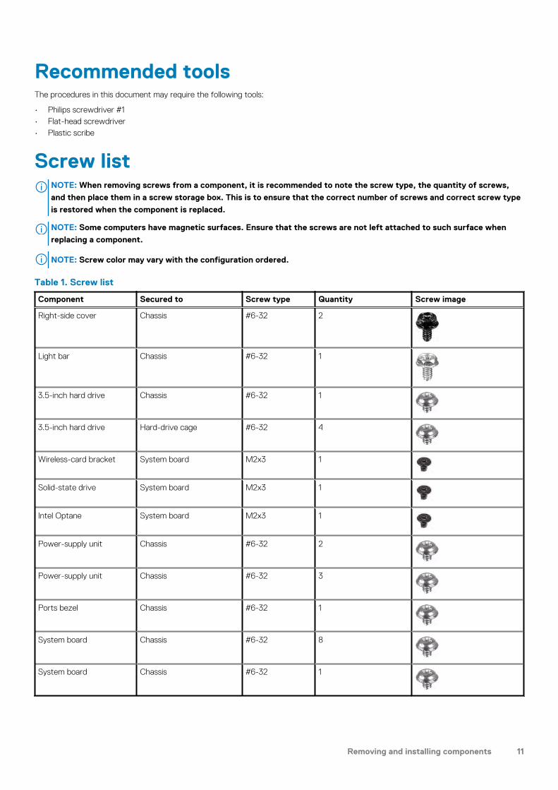
Recommended toolsThe procedures in this document may require the following tools:
• Philips screwdriver #1• Flat-head screwdriver• Plastic scribe
Screw listNOTE: When removing screws from a component, it is recommended to note the screw type, the quantity of screws,
and then place them in a screw storage box. This is to ensure that the correct number of screws and correct screw type
is restored when the component is replaced.
NOTE: Some computers have magnetic surfaces. Ensure that the screws are not left attached to such surface when
replacing a component.
NOTE: Screw color may vary with the configuration ordered.
Table 1. Screw list
Component Secured to Screw type Quantity Screw image
Right-side cover Chassis #6-32 2
Light bar Chassis #6-32 1
3.5-inch hard drive Chassis #6-32 1
3.5-inch hard drive Hard-drive cage #6-32 4
Wireless-card bracket System board M2x3 1
Solid-state drive System board M2x3 1
Intel Optane System board M2x3 1
Power-supply unit Chassis #6-32 2
Power-supply unit Chassis #6-32 3
Ports bezel Chassis #6-32 1
System board Chassis #6-32 8
System board Chassis #6-32 1
Removing and installing components 11

Left-side cover
Removing the left-side cover
Prerequisites
1. Follow the procedure in Before working inside your computer.
About this task
The following images indicate the location of the left-side cover and provides a visual representation of the removal procedure.
Steps
1. Loosen the two captive screws that secure the left-side cover to the chassis.2. Using the tab on the left-side cover, slide and lift the left-side cover off the chassis.
Installing the left-side cover
Prerequisites
If you are replacing a component, remove the existing component before performing the installation procedure.
About this task
The following images indicate the location of the left-side cover and provides a visual representation of the installation procedure.
12 Removing and installing components

Steps
1. Align the tabs on the left-side cover with the slots on the chassis, and slide it towards the front of the computer.2. Tighten the two captive screws that secure the left-side cover to the chassis.
Next steps
1. Follow the procedure in After working inside your computer.
Light bar
Removing the light bar
Prerequisites
1. Follow the procedure in Before working inside your computer.2. Remove the left-side cover.
About this task
The following images indicate the location of the light bar and provides a visual representation of the removal procedure.
Removing and installing components 13

Steps
1. Disconnect the light bar cable from its connector on the system board.2. Remove the light-bar cable from the routing guides.3. Remove the screw (#6-32) that secures the light bar to the chassis and lift the light bar off the tab.4. Release the tab on the other end of light bar from the slot on the chassis.5. Slide and remove the light bar off the chassis.
Installing the light bar
Prerequisites
If you are replacing a component, remove the existing component before performing the installation procedure.
About this task
The following images indicate the location of the light bar and provides a visual representation of the installation procedure.
14 Removing and installing components

Steps
1. Align and slide the tabs on the light bar into the slot on the chassis.2. Replace the screw (#6-32) that secures the light bar to the chassis.3. Connect the light bar cable to its connector on the system board.
Next steps
1. Install the left-side cover.2. Follow the procedure in After working inside your computer.
Front cover
Removing the front cover
Prerequisites
1. Follow the procedure in Before working inside your computer.2. Remove the left-side cover.
Removing and installing components 15
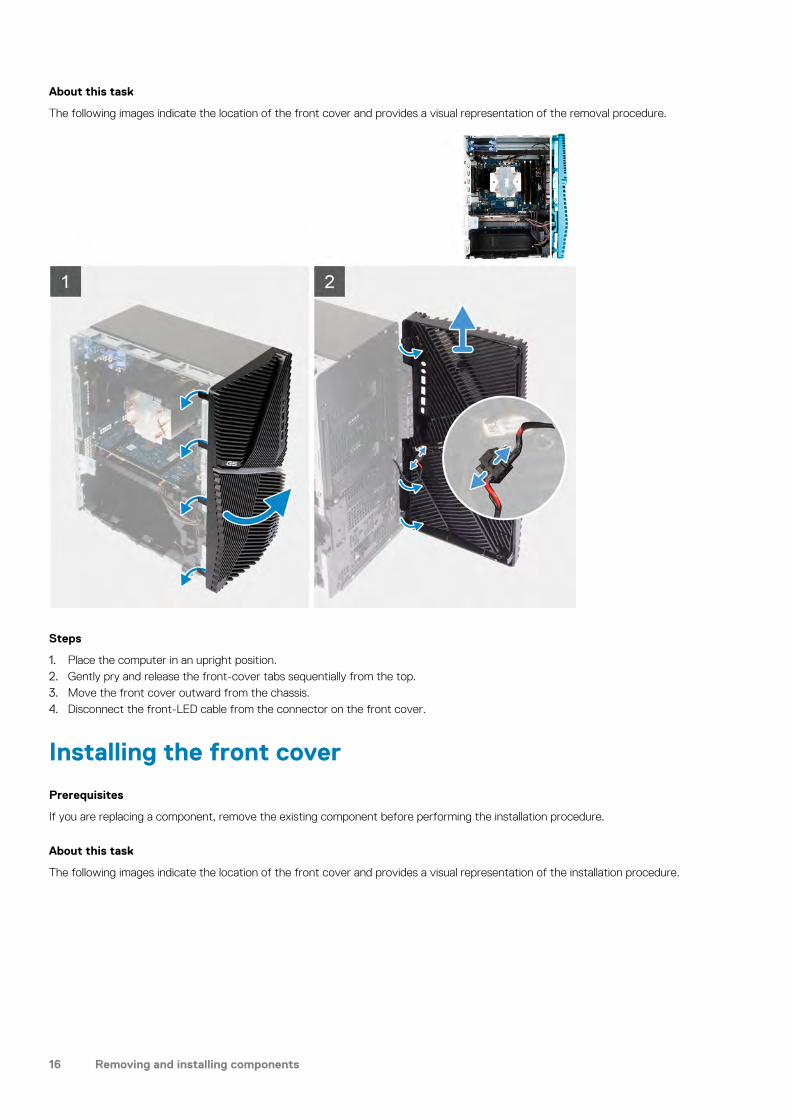
About this task
The following images indicate the location of the front cover and provides a visual representation of the removal procedure.
Steps
1. Place the computer in an upright position.2. Gently pry and release the front-cover tabs sequentially from the top.3. Move the front cover outward from the chassis.4. Disconnect the front-LED cable from the connector on the front cover.
Installing the front cover
Prerequisites
If you are replacing a component, remove the existing component before performing the installation procedure.
About this task
The following images indicate the location of the front cover and provides a visual representation of the installation procedure.
16 Removing and installing components

Steps
1. Place the computer in an upright position.2. Connect the front-LED cable to the connector on the front cover.3. Align the front-cover tabs with the slots on the chassis.4. Rotate the front cover towards the chassis and snap it into place.
Next steps
1. Install the left-side cover.2. Follow the procedure in After working inside your computer.
2.5-inch hard drive
Removing the 2.5-inch hard drive
Prerequisites
1. Follow the procedure in Before working inside your computer.2. Remove the left-side cover.
About this task
The following images indicate the location of the 2.5-inch hard-drive assembly and provides a visual representation of the removalprocedure.
Removing and installing components 17

NOTE: This computer is not shipped with a 2.5-inch hard drive installed. It is shipped with two empty 2.5-inch hard
drive cages and a SATA extension cable.
Steps
1. Disconnect the data and power cables from the hard drive.2. Press the release tabs on the hard-drive carrier and slide the hard-drive assembly out of the hard-drive cage.3. Pry the hard-drive carrier to release the tabs on the assembly from the slots on the hard drive.4. Lift and remove the hard drive off the hard-drive carrier.
NOTE: Note the orientation or the SATA connector marking on the hard-drive carrier so that you can replace it
correctly.
18 Removing and installing components

Installing the 2.5-inch hard drive
Prerequisites
If you are replacing a component, remove the existing component before performing the installation procedure.
About this task
The following images indicate the location of the 2.5-inch hard-drive assembly and provides a visual representation of the installationprocedure.
Removing and installing components 19

Steps
1. NOTE: Note the orientation or the SATA connector marking on the hard drive to replace it correctly.
Place the hard drive into the hard-drive carrier and align the tabs on the carrier with the slots on the hard drive.2. Slide the hard-drive assembly into the hard-drive cage until it snaps into place.3. Connect the data cable and power cable to the hard drive.
Next steps
1. Install the left-side cover.2. Follow the procedure in After working inside your computer.
3.5-inch hard drive
Removing the 3.5-inch hard drive
Prerequisites
1. Follow the procedure in Before working inside your computer.
20 Removing and installing components

2. Remove the left-side cover.
About this task
The following images indicate the location of the 3.5-inch hard-drive assembly and provides a visual representation of the removalprocedure.
Steps
1. Lay the computer on the right side.2. Remove the screw (#6-32) that secures the 3.5-inch hard-drive assembly to the chassis.3. Lift the hard-drive assembly away from the chassis.4. Remove the cables from the routing guides on the hard-drive assembly.5. Disconnect the data and power cables from the hard drive.6. Lift the hard-drive assembly away from the chassis.7. Remove the four screws (#6-32) that secure the the hard drive to the hard-drive cage.8. Slide the hard drive from the hard-drive cage.
Removing and installing components 21

Installing the 3.5-inch hard drive
Prerequisites
If you are replacing a component, remove the existing component before performing the installation procedure.
About this task
The following images indicate the location of the 3.5-inch hard-drive assembly and provides a visual representation of the installationprocedure.
Steps
1. Slide the hard drive into the hard-drive cage.2. Replace the four screws (#6-32) that secure the hard drive to the hard-drive cage.3. Align the hard-drive assembly with the tabs on the chassis.4. Using the alignment post, align the screw hole on the hard-drive assembly with the screw hole on the chassis.5. Route the power cable and data cable through the routing guides on the hard-drive assembly and connect the cables to the hard
drive.6. Replace the screw (#6-32) that secures the hard-drive assembly to the chassis.
22 Removing and installing components

Next steps
1. Install the left-side cover.2. Follow the procedure in After working inside your computer.
Chassis fan
Removing the chassis fan
Prerequisites
1. Follow the procedure in Before working inside your computer.2. Remove the left-side cover.3. Remove the light bar.
About this task
The following images indicate the location of the chassis fan and provides a visual representation of the removal procedure.
Steps
1. Lay the computer on the right side.2. Disconnect the fan cable from the system board.3. Gently pull the fan to release it from the rubber grommets.4. Remove the fan off the chassis.
Installing the chassis fan
Prerequisites
If you are replacing a component, remove the existing component before performing the installation procedure.
Removing and installing components 23

About this task
The following images indicate the location of the chassis fan and provides a visual representation of the installation procedure.
Steps
1. Align the slots on the fan with the rubber grommets on the chassis.
NOTE: The replaceable fan may have tabs inserted in the grommets slots to block the grommets slots and to avoid
incorrect installation on the fan. Service fan will have tabs plugged on one side to avoid incorrect installation of the
fan.
24 Removing and installing components
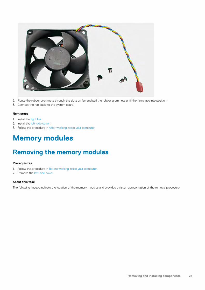
2. Route the rubber grommets through the slots on fan and pull the rubber grommets until the fan snaps into position.3. Connect the fan cable to the system board.
Next steps
1. Install the light bar.2. Install the left-side cover.3. Follow the procedure in After working inside your computer.
Memory modules
Removing the memory modules
Prerequisites
1. Follow the procedure in Before working inside your computer.2. Remove the left-side cover.
About this task
The following images indicate the location of the memory modules and provides a visual representation of the removal procedure.
Removing and installing components 25
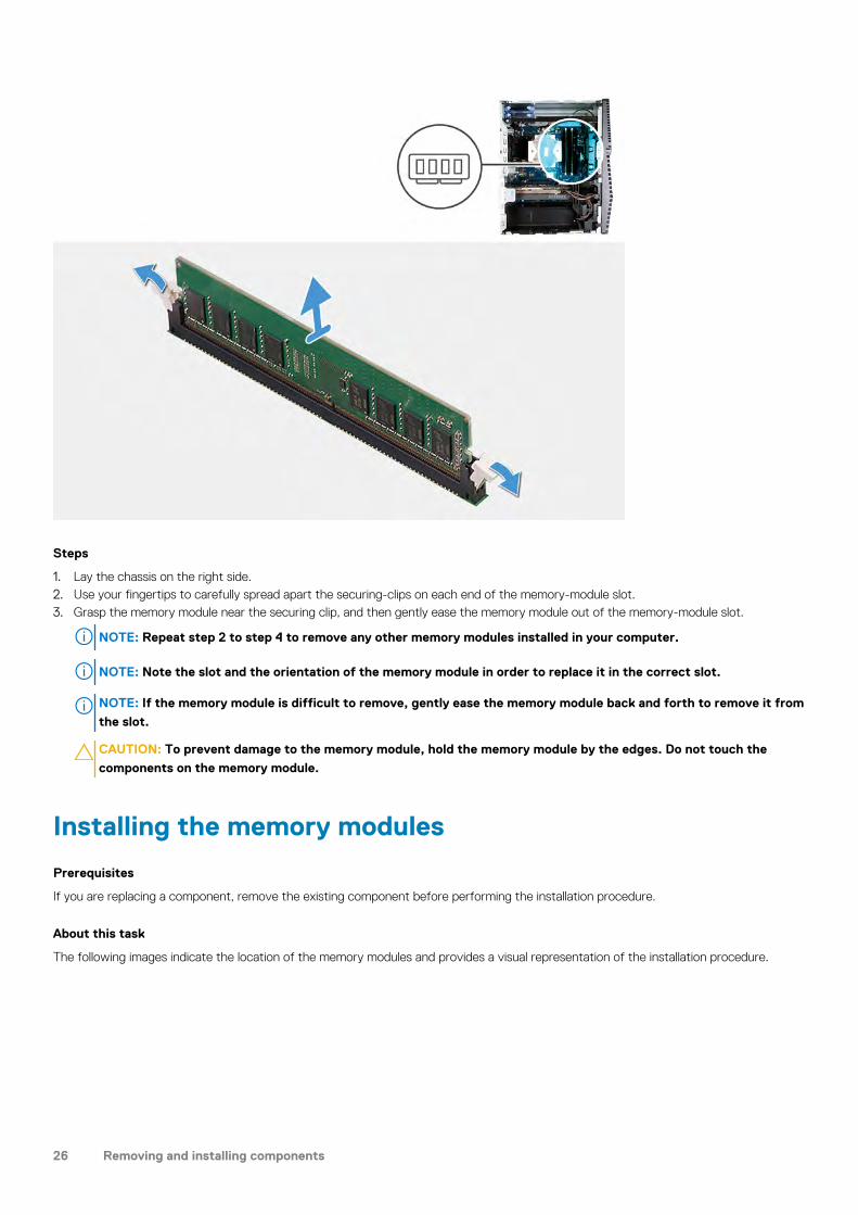
Steps
1. Lay the chassis on the right side.2. Use your fingertips to carefully spread apart the securing-clips on each end of the memory-module slot.3. Grasp the memory module near the securing clip, and then gently ease the memory module out of the memory-module slot.
NOTE: Repeat step 2 to step 4 to remove any other memory modules installed in your computer.
NOTE: Note the slot and the orientation of the memory module in order to replace it in the correct slot.
NOTE: If the memory module is difficult to remove, gently ease the memory module back and forth to remove it from
the slot.
CAUTION: To prevent damage to the memory module, hold the memory module by the edges. Do not touch the
components on the memory module.
Installing the memory modules
Prerequisites
If you are replacing a component, remove the existing component before performing the installation procedure.
About this task
The following images indicate the location of the memory modules and provides a visual representation of the installation procedure.
26 Removing and installing components

Steps
1. Align the notch on the memory module with the tab on the memory-module slot.2. Insert the memory module into the memory-module connector until the memory module snaps into position and the securing clip locks
in place.
NOTE: The securing clips return to the locked position. If you do not hear the click, remove the memory module and
reinstall it.
NOTE: If the memory module is difficult to remove, gently ease the memory module back and forth to remove it from
the slot.
CAUTION: To prevent damage to the memory module, hold the memory module by the edges. Do not touch the
components on the memory module.
Next steps
1. Install the left-side cover.2. Follow the procedure in After working inside your computer.
Wireless card
Removing the wireless card
Prerequisites
1. Follow the procedure in Before working inside your computer.2. Remove the left-side cover.3. Remove the 3.5-inch hard drive.
Removing and installing components 27

About this task
The following images indicate the location of the wireless card and provides a visual representation of the removal procedure.
Steps
1. Lay the computer on the right side.2. Remove the screw (M2x3) that secures the wireless card to the system board.3. Slide and lift the wireless-card bracket off the wireless card.4. Disconnect the antenna cables from the wireless card.5. Slide and remove the wireless card at an angle from the wireless-card slot.
Installing the wireless card
Prerequisites
If you are replacing a component, remove the existing component before performing the installation procedure.
NOTE: To avoid damage to the wireless card, do not place any cables under it.
28 Removing and installing components
About this task
The following images indicate the location of the wireless card and provides a visual representation of the installation procedure.
Steps
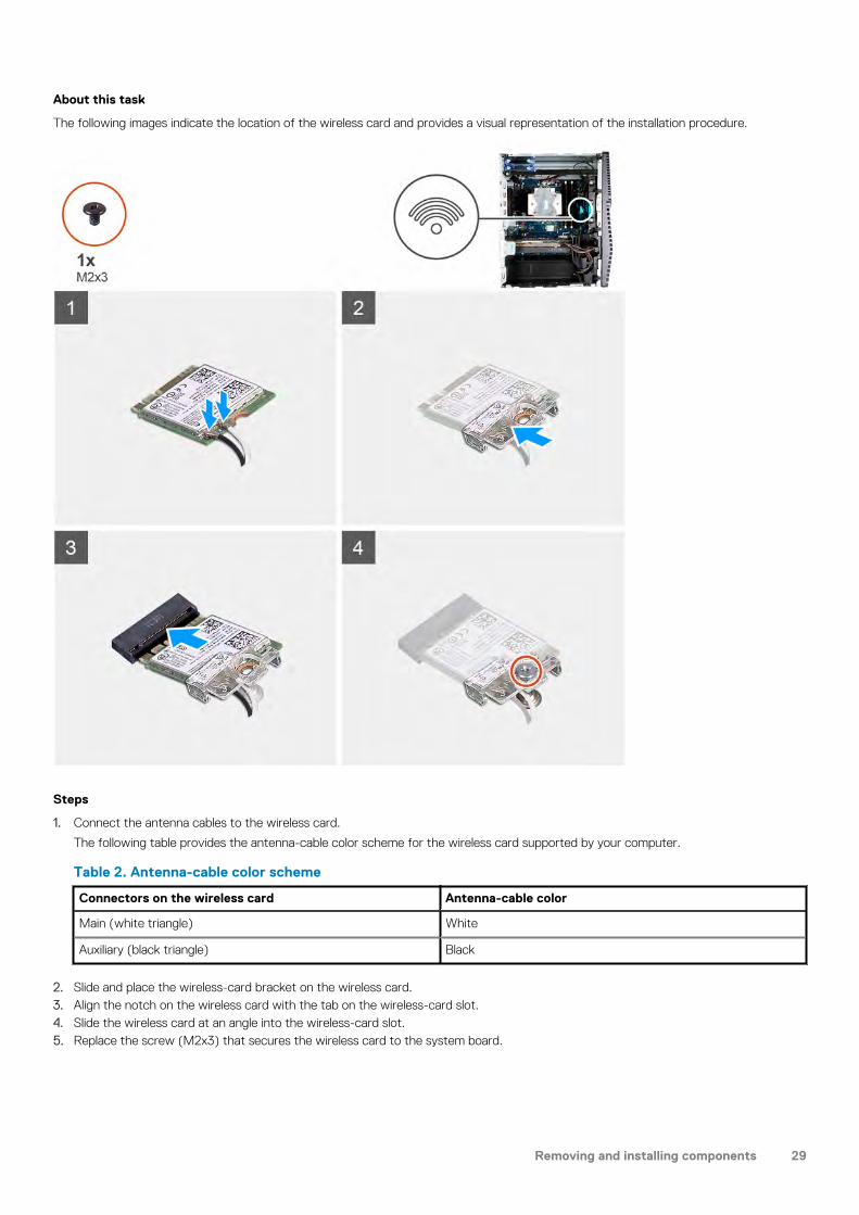
1. Connect the antenna cables to the wireless card.
The following table provides the antenna-cable color scheme for the wireless card supported by your computer.
Table 2. Antenna-cable color scheme
Connectors on the wireless card Antenna-cable color
Main (white triangle) White
Auxiliary (black triangle) Black
2. Slide and place the wireless-card bracket on the wireless card.3. Align the notch on the wireless card with the tab on the wireless-card slot.4. Slide the wireless card at an angle into the wireless-card slot.5. Replace the screw (M2x3) that secures the wireless card to the system board.
Removing and installing components 29

Next steps
1. Install the 3.5-inch hard drive.2. Install the left-side cover.3. Follow the procedure in After working inside your computer.
Solid-state drive/Intel Optane
Removing the solid-state drive/Intel Optane
Prerequisites
NOTE: You need to disable the Intel Optane memory before removing Intel Optane from your computer. For more
information about disabling the Intel Optane memory, see Disabling Intel Optane.
1. Follow the procedure in Before working inside your computer.2. Remove the left-side cover.3. Remove the graphics card.
About this task
The following images indicate the location of the solid-state drive/Intel Optane and provides a visual representation of the removalprocedure.
30 Removing and installing components

Steps
1. Remove the screw (M2x3) that secures the solid-state drive/Intel Optane to the system board.2. Slide and lift the solid-state drive/Intel Optane from the M.2 card slot on the system board.
Installing the solid-state drive/Intel Optane
Prerequisites
CAUTION: Solid-state drives are fragile. Exercise care when handling the solid-state drive.
If you are replacing a component, remove the existing component before performing the installation procedure.
About this task
The following images indicate the location of the solid-state drive/Intel Optane and provides a visual representation of the installationprocedure.
Removing and installing components 31

Steps
1. Locate the notch on the solid-state drive/Intel Optane.2. Align the notch on the solid-state drive/Intel Optane with the tab on the M.2 card slot.3. Slide the solid-state drive/Intel Optane into the M.2 card slot on the system board.4. Replace the screw (M2x3) that secures the solid-state drive/Intel Optane to the system board.
Next steps
1. Install the graphics card.2. Install the left-side cover.3. Follow the procedure in After working inside your computer.
NOTE: Enable the Intel Optane memory after you replace the Intel Optane memory module. For more information
about enabling the Intel Optane memory, see Enabling Intel Optane.
32 Removing and installing components

Graphics card
Removing the graphics card
Prerequisites
1. Follow the procedure in Before working inside your computer.2. Remove the left-side cover.
About this task
The following images indicate the location of the graphics card and provides a visual representation of the removal procedure.
Steps
1. Lay the computer on the right side.2. Locate the graphics card (PCI-Express).3. Disconnect the power cables from the graphics card and remove them from the routing guides on the graphics -card support bracket.
NOTE: This step is applicable only for computers that are shipped with a graphics-card support bracket.
Removing and installing components 33

4. Push the securing tabs on the graphics-card support bracket and rotate to remove it off the chassis.5. Lift the pull tab to open the PCIE door.6. Push and hold the securing tab on the graphics-card slot and lift the graphics card from the graphics-card slot.
NOTE: To remove the NVIDIA GeForce RTX 2080 graphics card, lift and rotate the graphics card.
Installing the graphics card
Prerequisites
If you are replacing a component, remove the existing component before performing the installation procedure.
About this task
The following images indicate the location of the graphics card and provides a visual representation of the installation procedure.
Steps
1. Align the graphics card with the PCI-Express card connector on the system board.
NOTE: To install the NVIDIA GeForce RTX 2080 graphics card, rotate and install the graphics card.
2. Using the alignment post, connect the card in the connector and press down firmly. Ensure that the card is firmly seated.
34 Removing and installing components

3. Close the PCIE door.4. Place the graphics-card support bracket that connects the graphics card.
NOTE: This step is applicable only for computers that are shipped with a graphics-card support bracket.
5. Route the cables through the routing guide on the graphics-card support bracket and connect the power cables to the graphics card.
Next steps
1. Install the right-side cover.2. Follow the procedure in After working inside your computer.
Coin-cell battery
Removing the coin-cell battery
Prerequisites
1. Follow the procedure in Before working inside your computer.NOTE: Before working inside your computer, read the safety information that shipped with your computer and
follow the steps in Before working inside your computer. After working inside your computer, follow the instructions
in After working inside your computer. For more safety best practices, see the Regulatory Compliance home page at
www.dell.com/regulatory_compliance.
CAUTION: Removing the coin-cell battery resets the BIOS setup program’s settings to default. It is recommended
that you note the BIOS setup program’s settings before removing the coin-cell battery.
2. Remove the left-side cover.3. Remove the graphics card.
About this task
The following images indicate the location of the coin-cell battery and provides a visual representation of the removal procedure.
Removing and installing components 35

Steps
1. Lay the computer on the right side.2. Using your finger, push the coin-cell battery-release lever on the coin-cell battery socket to release the coin-cell battery out of the
socket.3. Remove the coin-cell battery.
Installing the coin-cell battery
Prerequisites
If you are replacing a component, remove the existing component before performing the installation procedure.
About this task
The following images indicate the location of the coin-cell battery and provides a visual representation of the installation procedure.
Insert the coin-cell battery into the socket with the positive side (+) label facing up and snap the battery in the socket.
Next steps
1. Install the graphics card.2. Install the left-side cover.3. Follow the procedure in After working inside your computer.
Power-supply unit
Removing the power-supply unit
Prerequisites
1. Follow the procedure in Before working inside your computer.2. Remove the left-side cover.3. Remove the graphics card.
36 Removing and installing components

4. Remove the 3.5-inch hard drive.
NOTE: Note the routing of all cables as you remove them so that you can route them correctly while you are replacing
the power-supply unit.
About this task
The following images indicate the location of the power-supply unit and provides a visual representation of the removal procedure.
Removing and installing components 37

Steps
1. Lay the computer on the right side.2. Remove the two screws (#6-32) that secure the power-supply unit cover to the chassis.
NOTE: Only the computer with clear doors are shipped with power-supply unit cover. This step is applicable only for
computers shipped with power-supply unit cover.
3. Slide and lift the power-supply unit cover off the power-supply unit.4. Remove the three screws (#6-32) that secure the power-supply unit to the chassis.5. Disconnect the power cables from the system board and remove them from the routing guides on the chassis.6. Press the securing clip and slide the power-supply unit away from the back of the chassis.7. Lift the power-supply unit off the chassis.
Installing the power-supply unit
Prerequisites
If you are replacing a component, remove the existing component before performing the installation procedure.
WARNING: The cables and ports on the back of the power-supply unit are color-coded to indicate the different power
wattage. Ensure that you plug in the cable to the correct port. Failure to do so may result in damaging the power-supply
unit and/or system components.
About this task
The following images indicate the location of the power-supply unit and provides a visual representation of the installation procedure.
38 Removing and installing components

Removing and installing components 39

Steps
1. Slide the power-supply unit into the chassis until the securing tab snaps into position.2. Route the power cable through the routing guides on the chassis and connect the power cables to their respective connectors on the
system board.3. Replace the three screws (#6-32) that secure the power-supply unit to the chassis.4. Slide and align the screw holes on the power-supply unit cover with the screw holes on the chassis.
NOTE: Only the computer with clear doors are shipped with power-supply unit cover. This step is applicable only for
computers shipped with power-supply unit cover.
5. Replace the two screws (#6-32) that secure the power-supply unit to the chassis.
Next steps
1. Install the 3.5-inch hard drive.2. Install the graphics card.
40 Removing and installing components

3. Install the left-side cover.4. Follow the procedure in After working inside your computer.
Processor fan and heat-sink assembly
Removing the processor fan and heat-sink assembly
Prerequisites
1. Follow the procedure in Before working inside your computer.NOTE: The heat sink may become hot during normal operation. Allow sufficient time for the heat sink to cool before
you touch it.
CAUTION: For maximum cooling of the processor, do not touch the heat transfer areas on the heat sink. The oils in
your skin can reduce the heat transfer capability of the thermal grease.
2. Remove the left-side cover.
About this task
The following images indicate the location of the processor fan and heat-sink assembly and provides a visual representation of the removalprocedure.
Steps
1. Disconnect the processor-fan cable from the system board.2. In the reverse sequential order (4->3->2->1), loosen the captive screws that secure the processor fan and heat-sink assembly to the
system board.3. Lift the processor fan and heat-sink assembly off the system board.
Removing and installing components 41

Installing the processor fan and heat-sink assembly
Prerequisites
If you are replacing a component, remove the existing component before performing the installation procedure.
CAUTION: If either the processor or the heat sink is replaced, use the thermal grease provided in the kit to ensure that
thermal conductivity is achieved.
About this task
The following images indicate the location of the processor fan and heat-sink assembly and provides a visual representation of theinstallation procedure.
Steps
1. Align the numbering on the processor fan and heat-sink assembly with the numbering on the system board.2. In the sequential order (1->2->3->4), tighten the captive screws that secure the processor fan and heat-sink assembly to the system
board.3. Connect the processor-fan cable from the system board.
Next steps
1. Install the left-side cover.2. Follow the procedure in After working inside your computer.
42 Removing and installing components

Processor
Removing the processor
Prerequisites
1. Follow the procedure in Before working inside your computer.2. Remove the left-side cover.3. Remove the processor fan and heat-sink assembly.
WARNING: The processor might still be hot after the computer is shut down. Allow the processor to cool down before
removing it.
About this task
The following images indicate the location of the processor and provides a visual representation of the removal procedure.
Steps
1. Press the release lever down and then push it away from the processor to release it from the securing tab.2. Extend the release lever completely and open the processor cover.
Removing and installing components 43

CAUTION: When removing the processor, do not touch any of the pins inside the socket or allow any objects to fall
on the pins in the socket.
3. Gently lift the processor from the processor socket.
Installing the processor
Prerequisites
If you are replacing a component, remove the existing component before performing the installation procedure.
About this task
The following images indicate the location of the processor and provides a visual representation of the installation procedure.
Steps
1. Ensure that the release lever on the processor socket is fully extended in the open position.
NOTE: The pin-1 corner of the processor has a triangle that aligns with the triangle on the pin-1 corner on the
processor socket. When the processor is properly seated, all four corners are aligned at the same height. If one or
more corners of the processor are higher than the others, the processor is not seated properly.
44 Removing and installing components

2. Align the notches on the processor with the tabs on the processor socket and place the processor in the processor socket.
CAUTION: Ensure that the processor-cover notch is positioned underneath the alignment post.
3. When the processor is fully seated in the socket, pivot the release-lever down and place it under the tab on the processor cover.
Next steps
1. Install the processor fan and heat-sink assembly.2. Install the left-side cover.3. Follow the procedure in After working inside your computer.
VR heat sink
Removing the VR heat sink
Prerequisites
1. Follow the procedure in Before working inside your computer.NOTE: The heat sink may become hot during normal operation. Allow sufficient time for the heat sink to cool before
you touch it.
CAUTION: For maximum cooling of the processor, do not touch the heat transfer areas on the heat sink. The oils in
your skin can reduce the heat transfer capability of the thermal grease.
NOTE: The VR heat sink is shipped as a separate unit and it does not ship along with the system board. Ensure to
replace the VR heat sink from old system board to the new system board.
2. Remove the left-side cover.
About this task
The following images indicate the location of the VR heat sink and provides a visual representation of the removal procedure.
Removing and installing components 45

Steps
1. Loosen the captive screws that secure the VR heat sink to the system board.2. Lift the VR heat sink off the system board.
Installing the VR heat sink
Prerequisites
If you are replacing a component, remove the existing component before performing the installation procedure.
About this task
The following images indicate the location of the VR heat sink and provides a visual representation of the installation procedure.
46 Removing and installing components

Steps
1. Align and place the VR heat sink on the system board.2. Tighten the captive screws that secure the VR heat sink to the system board.
Next steps
1. Install the left-side cover.2. Follow the procedure in After working inside your computer.
LED daughter board
Removing the LED daughter board
Prerequisites
1. Follow the procedure in Before working inside your computer.2. Remove the left-side cover.
About this task
The following images indicate the location of the LED daughter board and provides a visual representation of the removal procedure.
Removing and installing components 47

Steps
1. Disconnect the light-bar cable and the front-LED cable from their respective connectors on the LED daughter board.2. Remove the screw (M2x3) that secures the LED daughter board to the system board.3. Slide and remove the LED daughter board off the system board.
Installing the LED daughter board
Prerequisites
If you are replacing a component, remove the existing component before performing the installation procedure.
About this task
The following images indicate the location of the LED daughter board and provides a visual representation of the removal procedure.
48 Removing and installing components

Steps
1. Slide the LED daughter board in place on the system board.2. Replace the screw (M2x3) that secures the LED daughter board to the system board.3. Connect the light-bar cable and the front-LED cable to their respective connectors on the LED daughter board.
Next steps
1. Install the left-side cover.2. Follow the procedure in After working inside your computer.
System board
Removing the system board
Prerequisites
1. Follow the procedure in Before working inside your computer.NOTE: Your computer’s Service Tag is stored in the system board. You must enter the Service Tag in the BIOS setup
program after you replace the system board.
NOTE: Replacing the system board removes any changes you have made to the BIOS using the BIOS setup program.
You must make the appropriate changes again after you replace the system board.
NOTE: Before disconnecting the cables from the system board, note the location of the connectors so that you can
reconnect the cables correctly after you replace the system board.
2. Remove the left-side cover.3. Remove the light bar.4. Remove the front cover5. Remove the memory modules.6. Remove the wireless card.7. Remove the solid-state drive/Intel Optane.8. Remove the graphics card.
Removing and installing components 49

9. Remove the coin-cell battery.10. Remove the processor fan and heat-sink assembly.11. Remove the processor.12. Remove the LED daughter board.
About this task
Figure 3. System-board components
1. wireless-card slot2. hard-drive data cable connector (SATA0)3. hard-drive power cable connector (SATA PWR)4. coin-cell battery5. power-supply unit cable connector6. graphics-card slot7. solid-state drive connector (m.2 PCIe SSD)8. chassis-fan cable connector (FAN SYS)9. processor10. processor-power cable connector (ATX CPU1)11. processor-power cable connector (ATX CPU)12. processor-fan cable connector (FAN CPU)13. memory-module slot (DIMM3)
50 Removing and installing components

14. memory-module slot (DIMM1)15. memory-module slot (DIMM4)16. memory-module slot (DIMM2)17. front LED cable connector (PWR SW)
The following images indicate the location of the system board and provides a visual representation of the removal procedure.
Removing and installing components 51

NOTE: Note the routing of all cables as you remove them so that you can route them correctly after you replace the
system board. For information on system-board connectors, see “System-board components”.
NOTE: Note the routing of all cables as you remove them so that you can route them correctly after you replace the
system board. For information on system-board connectors, see “System-board components”.
Steps
1. Lay the computer on the right side.2. Remove the screw (#6-32) that secures the front I/O-bracket to the chassis.3. Rotate and remove the front I/O-bracket from the chassis.4. Disconnect all the cables connected to the system board.5. Remove the eight screws (#6-32) and that secure the system board to the chassis.6. Remove the VR heat sink.
NOTE: The VR heat sink is shipped as a separate unit and it does not ship along with the system board. Ensure that
you replace the VR heat sink from old system board to the new system board.
7. Remove the screw (M2x4) and that secures the system board to the chassis.8. Lift the system board at an angle and remove it off the chassis.
Installing the system board
Prerequisites
If you are replacing a component, remove the existing component before performing the installation procedure.
52 Removing and installing components

About this task
Figure 4. System-board components
1. wireless-card slot2. hard-drive data cable connector (SATA0)3. hard-drive power cable connector (SATA PWR)4. coin-cell battery5. power-supply unit cable connector6. graphics-card slot7. solid-state drive connector (m.2 PCIe SSD)8. chassis-fan cable connector (FAN SYS)9. processor10. processor-power cable connector (ATX CPU1)11. processor-power cable connector (ATX CPU)12. processor-fan cable connector (FAN CPU)13. memory-module slot (DIMM3)14. memory-module slot (DIMM1)15. memory-module slot (DIMM4)16. memory-module slot (DIMM2)17. front LED cable connector (PWR SW)
The following images indicate the location of the system board and provides a visual representation of the installation procedure.
Removing and installing components 53

54 Removing and installing components

Steps
1. Slide the back I/O-ports on the system board into the front I/O-slots on the chassis and align the screw holes on the system boardwith the screw holes on the chassis.
2. Replace the screw (M2x4) that secures the system board to the chassis.3. Install the VR heat sink.
NOTE: The VR heat sink is shipped as a separate unit and it does not ship along with the system board. Ensure that
you replace the VR heat sink from old system board to the new system board.
4. Replace the eight screws (#6-32) that secure the system board to the chassis.5. Route and connect all the cables that you disconnected from the system board.
NOTE: For information on system-board connectors, see “System-board components”.
6. Align the front I/O-bracket with the slots on the chassis.7. Replace the screw (#6-32) that secures the front I/O-bracket to the chassis.
Removing and installing components 55

Next steps
1. Install the LED daughter board.2. Install the processor.3. Install the processor fan and heat-sink assembly.4. Install the coin-cell battery.5. Install the graphics card.6. Install the solid-state drive/Intel Optane.7. Install the wireless card.8. Install the memory module.9. Install the front cover.10. Install the light bar.11. Install the left-side cover.12. Follow the procedure in After working inside your computer.
NOTE: Your computer’s Service Tag is stored in the system board. You must enter the Service Tag in the BIOS setup
program after you replace the system board.
NOTE: Replacing the system board removes any changes you have made to the BIOS using the BIOS setup program.
You must make the appropriate changes again after you replace the system board.
56 Removing and installing components

Device drivers
Operating system• Windows 10 Home (64-bit)• Windows 10 Professional (64-bit)
Downloading the audio driverSteps
1. Turn on your computer.2. Go to www.dell.com/support.3. Enter the Service Tag of your computer, and then click Submit.
NOTE: If you do not have the Service Tag, use the auto-detect feature or manually browse for your computer model.
4. Click Drivers & downloads.5. Click the Detect Drivers button.6. Review and agree to the Terms and Conditions to use SupportAssist, then click Continue.7. If necessary, your computer starts to download and install SupportAssist.
NOTE: Review on-screen instructions for browser-specific instructions.
8. Click View Drivers for My System.9. Click Download and Install to download and install all driver updates detected for your computer.10. Select a location to save the files.11. If prompted, approve requests from User Account Control to make changes on the system.12. The application installs all drivers and updates identified.
NOTE: Not all files can be installed automatically. Review the installation summary to identify if manual installation is
necessary.
13. For manual download and installation, click Category.14. Click Audio in the drop-down list.15. Click Download to download the audio driver for your computer.16. After the download is complete, navigate to the folder where you saved the audio driver file.17. Double-click the audio driver file icon and follow the instructions on the screen to install the driver.
Downloading the graphics driverSteps
1. Turn on your computer.2. Go to www.dell.com/support.3. Enter the Service Tag of your computer, and then click Submit.
NOTE: If you do not have the Service Tag, use the auto-detect feature or manually browse for your computer model.
4. Click Drivers & downloads.5. Click the Detect Drivers button.6. Review and agree to the Terms and Conditions to use SupportAssist, then click Continue.7. If necessary, your computer starts to download and install SupportAssist.
3
Device drivers 57

NOTE: Review on-screen instructions for browser-specific instructions.
8. Click View Drivers for My System.9. Click Download and Install to download and install all driver updates detected for your computer.10. Select a location to save the files.11. If prompted, approve requests from User Account Control to make changes on the system.12. The application installs all drivers and updates identified.
NOTE: Not all files can be installed automatically. Review the installation summary to identify if manual installation is
necessary.
13. For manual download and installation, click Category.14. Click Video in the drop-down list.15. Click Download to download the graphics driver for your computer.16. After the download is complete, navigate to the folder where you saved the graphics driver file.17. Double-click the graphics driver file icon and follow the instructions on the screen to install the driver.
Downloading the USB driverSteps
1. Turn on your computer.2. Go to www.dell.com/support.3. Enter the Service Tag of your computer, and then click Submit.
NOTE: If you do not have the Service Tag, use the auto-detect feature or manually browse for your computer model.
4. Click Drivers & downloads.5. Click the Detect Drivers button.6. Review and agree to the Terms and Conditions to use SupportAssist, then click Continue.7. If necessary, your computer starts to download and install SupportAssist.
NOTE: Review on-screen instructions for browser-specific instructions.
8. Click View Drivers for My System.9. Click Download and Install to download and install all driver updates detected for your computer.10. Select a location to save the files.11. If prompted, approve requests from User Account Control to make changes on the system.12. The application installs all drivers and updates identified.
NOTE: Not all files can be installed automatically. Review the installation summary to identify if manual installation is
necessary.
13. For manual download and installation, click Category.14. Click Chipset in the drop-down list.15. Click Download to download the USB driver for your computer.16. After the download is complete, navigate to the folder where you saved the USB driver file.17. Double-click the USB driver file icon and follow the instructions on the screen to install the driver.
Downloading the WiFi driverSteps
1. Turn on your computer.2. Go to www.dell.com/support.3. Enter the Service Tag of your computer, and then click Submit.
NOTE: If you do not have the Service Tag, use the auto-detect feature or manually browse for your computer model.
4. Click Drivers & downloads.
58 Device drivers

5. Click the Detect Drivers button.6. Review and agree to the Terms and Conditions to use SupportAssist, then click Continue.7. If necessary, your computer starts to download and install SupportAssist.
NOTE: Review on-screen instructions for browser-specific instructions.
8. Click View Drivers for My System.9. Click Download and Install to download and install all driver updates detected for your computer.10. Select a location to save the files.11. If prompted, approve requests from User Account Control to make changes on the system.12. The application installs all drivers and updates identified.
NOTE: Not all files can be installed automatically. Review the installation summary to identify if manual installation is
necessary.
13. For manual download and installation, click Category.14. Click Network in the drop-down list.15. Click Download to download the WiFi driver for your computer.16. After the download is complete, navigate to the folder where you saved the WiFi driver file.17. Double-click the WiFi driver icon and follow the instructions on the screen to install the driver.
Downloading the chipset driverSteps
1. Turn on your computer.2. Go to www.dell.com/support.3. Enter the Service Tag of your computer, and then click Submit.
NOTE: If you do not have the Service Tag, use the auto-detect feature or manually browse for your computer model.
4. Click Drivers & downloads.5. Click the Detect Drivers button.6. Review and agree to the Terms and Conditions to use SupportAssist, then click Continue.7. If necessary, your computer starts to download and install SupportAssist.
NOTE: Review on-screen instructions for browser-specific instructions.
8. Click View Drivers for My System.9. Click Download and Install to download and install all driver updates detected for your computer.10. Select a location to save the files.11. If prompted, approve requests from User Account Control to make changes on the system.12. The application installs all drivers and updates identified.
NOTE: Not all files can be installed automatically. Review the installation summary to identify if manual installation is
necessary.
13. For manual download and installation, click Category.14. Click Chipset in the drop-down list.15. Click Download to download the chipset driver for your computer.16. After the download is complete, navigate to the folder where you saved the saved the chipset driver file.17. Double-click the chipset driver file icon and follow the instructions on the screen to install the driver.
Downloading the network driverSteps
1. Turn on your computer.2. Go to www.dell.com/support.3. Enter the Service Tag of your computer, and then click Submit.
Device drivers 59

NOTE: If you do not have the Service Tag, use the auto-detect feature or manually browse for your computer model.
4. Click Drivers & downloads.5. Click the Detect Drivers button.6. Review and agree to the Terms and Conditions to use SupportAssist, then click Continue.7. If necessary, your computer starts to download and install SupportAssist.
NOTE: Review on-screen instructions for browser-specific instructions.
8. Click View Drivers for My System.9. Click Download and Install to download and install all driver updates detected for your computer.10. Select a location to save the files.11. If prompted, approve requests from User Account Control to make changes on the system.12. The application installs all drivers and updates identified.
NOTE: Not all files can be installed automatically. Review the installation summary to identify if manual installation is
necessary.
13. For manual download and installation, click Category.14. Click Network in the drop-down list.15. Click Download to download the network driver for your computer.16. After the download is complete, navigate to the folder where you saved the network driver file.17. Double-click the network driver file icon and follow the instructions on the screen to install the driver.
60 Device drivers

System setup
NOTE: Depending on the computer and its installed devices, the items listed in this section may or may not be displayed.
System setupCAUTION: Unless you are an expert computer user, do not change the settings in the BIOS Setup program. Certain
changes can make your computer work incorrectly.
NOTE: Before you change BIOS Setup program, it is recommended that you write down the BIOS Setup program screen
information for future reference.
Use the BIOS Setup program for the following purposes:
• Get information about the hardware installed in your computer, such as the amount of RAM and the size of the hard drive.• Change the system configuration information.• Set or change a user-selectable option, such as the user password, type of hard drive installed, and enabling or disabling base devices.
BIOS overviewThe BIOS manages data flow between the computer's operating system and attached devices such as hard disk, video adapter, keyboard,mouse, and printer.
Entering BIOS setup programAbout this task
Turn on (or restart) your computer and press F2 immediately.
Navigation keysNOTE: For most of the System Setup options, changes that you make are recorded but do not take effect until you
restart the system.
Keys Navigation
Up arrow Moves to the previous field.
Down arrow Moves to the next field.
Enter Selects a value in the selected field (if applicable) or follow the link in the field.
Spacebar Expands or collapses a drop-down list, if applicable.
Tab Moves to the next focus area.
Esc Moves to the previous page until you view the main screen. Pressing Esc in the main screen displays a messagethat prompts you to save any unsaved changes and restarts the system.
Boot SequenceBoot Sequence allows you to bypass the System Setup–defined boot device order and boot directly to a specific device (for example:optical drive or hard drive). During the Power-on Self Test (POST), when the Dell logo appears, you can:
• Access System Setup by pressing F2 key
4
System setup 61

• Bring up the one-time boot menu by pressing F12 key
The one-time boot menu displays the devices that you can boot from including the diagnostic option. The boot menu options are:
• Removable Drive (if available)• STXXXX Drive (if available)
NOTE: XXX denotes the SATA drive number.
• Optical Drive (if available)• SATA Hard Drive (if available)• Diagnostics
NOTE: Choosing Diagnostics, will display the ePSA diagnostics screen.
The boot sequence screen also displays the option to access the System Setup screen.
System setup optionsNOTE: Depending on this computer and its installed devices, the items listed in this section may or may not appear.
Table 3. System setup options—System information menu
General-System Information
System Information
BIOS Version Displays the BIOS version number.
Service Tag Displays the Service Tag of the computer.
Asset Tag Displays the Asset Tag of the computer.
Ownership Tag Displays the ownership tag of the computer.
Manufacture Date Displays the manufacture date of the computer.
Ownership Date Displays the ownership date of the computer.
Express Service Code Displays the express service code of the computer.
Memory Information
Memory Installed Displays the total computer memory installed.
Memory Available Displays the total computer memory available.
Memory Speed Displays the memory speed.
Memory Channel Mode Displays single or dual channel mode.
Memory Technology Displays the technology used for the memory.
DIMM 1 Size Displays the DIMM 1 memory size.
DIMM 2 Size Displays the DIMM 2 memory size.
DIMM 3 Size Displays the DIMM 3 memory size.
DIMM 4 Size Displays the DIMM 4 memory size.
PCI Information
SLOT1 Displays the PCI information of the computer.
SLOT2 Displays the PCI information of the computer.
SLOT4 Displays the PCI information of the computer.
SLOT5_M.2 Displays the PCI information of the computer.
SLOT6_M.2 Displays the PCI information of the computer.
Processor Information
Processor Type Displays the processor type.
Core Count Displays the number of cores on the processor.
62 System setup
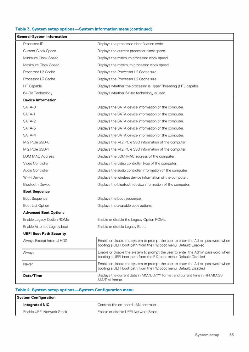
Table 3. System setup options—System information menu(continued)
General-System Information
Processor ID Displays the processor identification code.
Current Clock Speed Displays the current processor clock speed.
Minimum Clock Speed Displays the minimum processor clock speed.
Maximum Clock Speed Displays the maximum processor clock speed.
Processor L2 Cache Displays the Processor L2 Cache size.
Processor L3 Cache Displays the Processor L2 Cache size.
HT Capable Displays whether the processor is HyperThreading (HT) capable.
64-Bit Technology Displays whether 64-bit technology is used.
Device Information
SATA-0 Displays the SATA device information of the computer.
SATA-1 Displays the SATA device information of the computer.
SATA-2 Displays the SATA device information of the computer.
SATA-3 Displays the SATA device information of the computer.
SATA-4 Displays the SATA device information of the computer.
M.2 PCIe SSD-0 Displays the M.2 PCIe SSD information of the computer.
M.2 PCIe SSD-1 Displays the M.2 PCIe SSD information of the computer.
LOM MAC Address Displays the LOM MAC address of the computer.
Video Controller Displays the video controller type of the computer.
Audio Controller Displays the audio controller information of the computer.
Wi-Fi Device Displays the wireless device information of the computer.
Bluetooth Device Displays the bluetooth device information of the computer.
Boot Sequence
Boot Sequence Displays the boot sequence.
Boot List Option Displays the available boot options.
Advanced Boot Options
Enable Legacy Option ROMs Enable or disable the Legacy Option ROMs.
Enable Attempt Legacy boot Enable or disable Legacy Boot.
UEFI Boot Path Security
Always,Except Internal HDD Enable or disable the system to prompt the user to enter the Admin password whenbooting a UEFI boot path from the F12 boot menu. Default: Enabled
Always Enable or disable the system to prompt the user to enter the Admin password whenbooting a UEFI boot path from the F12 boot menu. Default: Disabled
Never Enable or disable the system to prompt the user to enter the Admin password whenbooting a UEFI boot path from the F12 boot menu. Default: Disabled
Date/Time Displays the current date in MM/DD/YY format and current time in HH:MM:SSAM/PM format.
Table 4. System setup options—System Configuration menu
System Configuration
Integrated NIC Controls the on-board LAN controller.
Enable UEFI Network Stack Enable or disable UEFI Network Stack.
System setup 63

Table 4. System setup options—System Configuration menu(continued)
System Configuration
Front bezel LED Light Intensity Control Enable, disable or adjust the Front bezel LED Light Intensity to Low or medium.
Serial port Enable or disable the serial ports.
SATA Operation Configure operating mode of the integrated SATA hard drive controller.
Drives Enable or disable various drives on board.
SATA-0 Displays the SATA device information of the computer.
SATA-1 Displays the SATA device information of the computer.
SATA-2 Displays the SATA device information of the computer.
SATA-3 Displays the SATA device information of the computer.
SATA-4 Displays the SATA device information of the computer.
M.2 PCIe SSD-0 Displays the M.2 PCIe SSD information of the computer.
M.2 PCIe SSD-1 Displays the M.2 PCIe SSD information of the computer.
SMART Reporting Enable or disable SMART Reporting during system startup.
USB Configuration
Enable Boot Support Enable or disable booting from USB mass storage devices such as external harddrive, optical drive, and USB drive.
Enable front USB Port Enable or disable the front USB ports.
Enable internal USB Port Enable or disable booting from USB mass storage devices connected to internal USBport.
Enable rear USB Port Enable or disable the rear USB ports.
Front USB Configuration Enable or disable the front USB ports.
Rear USB Configuration Enable or disable the rear USB ports.
Thunderbolt Adapter Configuration Enable or disable Thunderbolt technology support.
Auto switch Enable or disable the auto switch.
Native enumeration Enable or disable the native enumeration.
BIOS Assist enumeration Enable or disable the BIOS Assist enumeration.
USB Powershare Enable or disable the USB powershare.
Audio Enable or disable the integrated audio controller.
Dust Filter Maintenance Enable or disable various onboard devices.
Miscellaneous Devices Enable or disable various onboard devices.
Watchdog Timer support Enable or disable the watchdog timer support.
Table 5. System setup options—Video menu
Video
Multi-Display Enable or disable multiple displays.
Primary Display Set or change the primary display.
Table 6. System setup options—Security menu
Security
Admin Password Set, change, or delete the administrator password.
System Password Set, change, or delete the system password.
Internal HDD-0 Password Set, change, or delete the internal hard-disk drive password.
64 System setup

Table 6. System setup options—Security menu(continued)
Security
Internal HDD-1 Password Set, change, or delete the internal hard-disk drive password.
Internal HDD-2 Password Set, change, or delete the internal hard-disk drive password.
Internal HDD-3 Password Set, change, or delete the internal hard-disk drive password.
M.2 SATA SSD Password Set, change, or delete the M.2 solid-state drive password.
Strong Password Enable or disable strong passwords.
Password Configuration Control the minimum and maximum number of characters allowed for Admin andSystem passwords.
Password Bypass Bypass the System (Boot) Password and the internal HDD password prompts duringa system restart.
Password Change Enable or disable changes to the System and Hard Disk passwords when anadministrator password is set.
UEFI Capsule Firmware Updates Enable or disable BIOS updates through UEFI capsule update packages.
TPM 1.2 Security Enable or disable the firmware TPM 1.2 function.
TPM 2.0 Security Enable or disable the firmware TPM 2.0 function.
TPM Security Enable or disable the firmware TPM function.
PTT Security
PTT On Enable or disable Platform Trust Technology (PTT) visibility to the operating system.
Clear Default: Disabled
PPI ByPass for Clear Command Enable or disable the TPM Physical Presence Interface (PPI). When enabled, thissetting will allow the OS to skip BIOS PPI user prompts when issuing the Clearcommand. Changes to this setting take effect immediately.Default: Disabled
Computrace(R) Enable or disable the BIOS module interface of the optional Computrace(R) Servicefrom Absolute Software.
Admin Setup Lockout Enable to prevent users from entering Setup when an Admin Password is set.
Master Password Lockout Disables the master password support. Hard Disk passwords need to be clearedbefore changing the setting.
HDD protection Set, change, or delete the hard-disk drive password.
SMM Security Mitigation Enable or disable SMM Security Mitigation
Table 7. System setup options—Secure Boot menu
Secure Boot
Secure Boot Enable Enable or disable the secure boot feature.
Secure Boot Mode Modifies the behavior of Secure Boot to allow evaluation or enforcement of UEFIdriver signatures.
• Deployed Mode-Default: Enabled• Audit Mode-Default: Disabled
Deployed Mode Enable or disable the deployed mode.
Audit Mode Enable or disable the audit mode.
Expert Key Management
Expert Key Management Enable or disable Expert Key Management.
Custom Mode Key Management Select the custom values for expert key management.
System setup 65
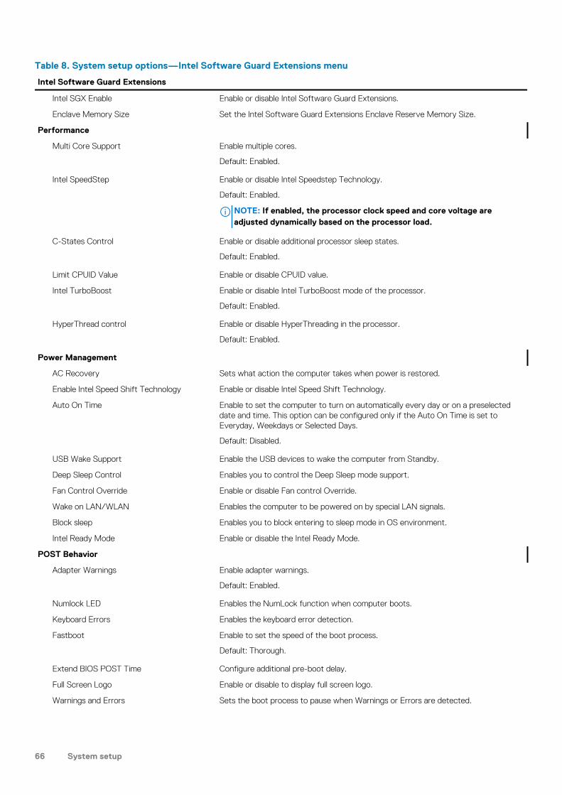
Table 8. System setup options—Intel Software Guard Extensions menu
Intel Software Guard Extensions
Intel SGX Enable Enable or disable Intel Software Guard Extensions.
Enclave Memory Size Set the Intel Software Guard Extensions Enclave Reserve Memory Size.
Performance
Multi Core Support Enable multiple cores.
Default: Enabled.
Intel SpeedStep Enable or disable Intel Speedstep Technology.
Default: Enabled.
NOTE: If enabled, the processor clock speed and core voltage areadjusted dynamically based on the processor load.
C-States Control Enable or disable additional processor sleep states.
Default: Enabled.
Limit CPUID Value Enable or disable CPUID value.
Intel TurboBoost Enable or disable Intel TurboBoost mode of the processor.
Default: Enabled.
HyperThread control Enable or disable HyperThreading in the processor.
Default: Enabled.
Power Management
AC Recovery Sets what action the computer takes when power is restored.
Enable Intel Speed Shift Technology Enable or disable Intel Speed Shift Technology.
Auto On Time Enable to set the computer to turn on automatically every day or on a preselecteddate and time. This option can be configured only if the Auto On Time is set toEveryday, Weekdays or Selected Days.
Default: Disabled.
USB Wake Support Enable the USB devices to wake the computer from Standby.
Deep Sleep Control Enables you to control the Deep Sleep mode support.
Fan Control Override Enable or disable Fan control Override.
Wake on LAN/WLAN Enables the computer to be powered on by special LAN signals.
Block sleep Enables you to block entering to sleep mode in OS environment.
Intel Ready Mode Enable or disable the Intel Ready Mode.
POST Behavior
Adapter Warnings Enable adapter warnings.
Default: Enabled.
Numlock LED Enables the NumLock function when computer boots.
Keyboard Errors Enables the keyboard error detection.
Fastboot Enable to set the speed of the boot process.
Default: Thorough.
Extend BIOS POST Time Configure additional pre-boot delay.
Full Screen Logo Enable or disable to display full screen logo.
Warnings and Errors Sets the boot process to pause when Warnings or Errors are detected.
66 System setup

Table 9. System setup options—Virtualization Support menu
Virtualization Support
Virtualization Specify whether a Virtual Machine Monitor (VMM) can utilize the additionalhardware capabilities provided by Intel Virtualization Technology.
VT for Direct I/O Specify whether a Virtual Machine Monitor (VMM) can utilize the additionalhardware capabilities provided by Intel Virtualization Technology for Direct I/O.
Trusted Execution Enable or disable trusted execution.
Table 10. System setup options—Wireless menu
Wireless
Wireless Device Enable Enable or disable internal wireless devices.
Table 11. System setup options—Maintenance menu
Maintenance
Service Tag Display the system’s Service Tag.
Asset Tag Create a system Asset Tag.
SERR Messages Enable or disable SERR messages.
Dell development configuration Enable or disable Dell development configuration.
BIOS Downgrade Control flashing of the system firmware to previous revisions.
Data Wipe Enable to securely erase data from all internal storage devices.
BIOS Recovery Enable the user to recover from certain corrupted BIOS conditions from a recoveryfile on the user primary hard drive or an external USB key.
Table 12. System setup options—System Logs menu
System Logs
BIOS Events Display BIOS events.
Table 13. System setup options—SupportAssist System Resolution menu
SupportAssist System Resolution
Auto OS Recovery Threshold Control the automatic boot flow for SupportAssist System Resolution Console andfor Dell OS Recovery tool.
System and setup passwordTable 14. System and setup password
Password type Description
System password Password that you must enter to log on to your system.
Setup password Password that you must enter to access and make changes to theBIOS settings of your computer.
You can create a system password and a setup password to secure your computer.
CAUTION: The password features provide a basic level of security for the data on your computer.
CAUTION: Anyone can access the data stored on your computer if it is not locked and left unattended.
NOTE: System and setup password feature is disabled.
System setup 67

Assigning a system setup password
Prerequisites
You can assign a new System or Admin Password only when the status is in Not Set.
About this task
To enter the system setup, press F2 immediately after a power-on or re-boot.
Steps
1. In the System BIOS or System Setup screen, select Security and press Enter.The Security screen is displayed.
2. Select System/Admin Password and create a password in the Enter the new password field.
Use the following guidelines to assign the system password:
• A password can have up to 32 characters.• The password can contain the numbers 0 through 9.• Only lower case letters are valid, upper case letters are not allowed.• Only the following special characters are allowed: space, (”), (+), (,), (-), (.), (/), (;), ([), (\), (]), (`).
3. Type the system password that you entered earlier in the Confirm new password field and click OK.4. Press Esc and a message prompts you to save the changes.5. Press Y to save the changes.
The computer reboots.
Deleting or changing an existing system setup password
Prerequisites
Ensure that the Password Status is Unlocked (in the System Setup) before attempting to delete or change the existing System and/orSetup password. You cannot delete or change an existing System or Setup password, if the Password Status is Locked.
About this task
To enter the System Setup, press F2 immediately after a power-on or reboot.
Steps
1. In the System BIOS or System Setup screen, select System Security and press Enter.The System Security screen is displayed.
2. In the System Security screen, verify that Password Status is Unlocked.3. Select System Password, alter or delete the existing system password and press Enter or Tab.4. Select Setup Password, alter or delete the existing setup password and press Enter or Tab.
NOTE: If you change the System and/or Setup password, re-enter the new password when prompted. If you delete
the System and/or Setup password, confirm the deletion when prompted.
5. Press Esc and a message prompts you to save the changes.6. Press Y to save the changes and exit from System Setup.
The computer reboot.
Clearing CMOS settings
About this task
CAUTION: Clearing CMOS settings will reset the BIOS settings on your computer.
68 System setup

Steps
1. Remove the left-side cover.2. Remove the graphics card.3. Remove the jumper plug from the password jumper-pins (PSWD) and connect it to the CMOS jumper-pins.4. Wait for 5 seconds and then replace the jumper plug to its original location.
5. Install the graphics card.6. Install the left-side cover.
Clearing BIOS (System Setup) and System passwords
About this task
CAUTION: Clearing CMOS settings will reset the BIOS settings on your computer.
Steps
1. Remove the left-side cover.2. Remove the graphics card.3. Remove the jumper plug from the password jumper-pins (PSWD).4. Wait for 5 seconds and then replace the jumper plug to its original location.
System setup 69

5. Install the graphics card.6. Install the left-side cover.
70 System setup

Troubleshooting
Enhanced Pre-Boot System Assessment (ePSA)diagnosticsAbout this task
The ePSA diagnostics (also known as system diagnostics) performs a complete check of your hardware. The ePSA is embedded with theBIOS and is launched by the BIOS internally. The embedded system diagnostics provides a set of options for particular devices or devicegroups allowing you to:
• Run tests automatically or in an interactive mode• Repeat tests• Display or save test results• Run thorough tests to introduce additional test options to provide extra information about the failed device(s)• View status messages that inform you if tests are completed successfully• View error messages that inform you of problems encountered during testing
NOTE: Some tests for specific devices require user interaction. Always ensure that you are present at the computer
terminal when the diagnostic tests are performed.
For more information, see Dell EPSA Diagnostic 3.0.
Running the ePSA diagnostics
Steps
1. Turn on your computer.2. As the computer boots, press the F12 key as the Dell logo appears.3. On the boot menu screen, select the Diagnostics option.4. Click the arrow at the bottom left corner.
Diagnostics front page is displayed.5. Click the arrow in the lower-right corner to go to the page listing.
The items detected are listed.6. To run a diagnostic test on a specific device, press Esc and click Yes to stop the diagnostic test.7. Select the device from the left pane and click Run Tests.8. If there are any issues, error codes are displayed.
Note the error code and validation number and contact Dell.
DiagnosticsThe computer POST (Power On Self-Test) ensures that it meets the basic computer requirements and the hardware is workingappropriately before the boot process begins. If the computer passes the POST, the computer continues to start in a normal mode.However, if the computer fails the POST, the computer emits a series of LED codes during the start-up. The system LED is integrated onthe Power button.
The following table shows different light patterns and what they indicate.
5
Troubleshooting 71

Table 15. Power LED summary
Amber LED state White LED state System state Description
Off Off S4, S5 • Hibernate or Suspend toDisk (S4)
• Power is off (S5)
Off Blinking S1, S3 System is in a low-power state,either S1 or S3. This does notindicate a fault condition.
Previous State Previous State S3, no PWRGD_PS This entry provides for thepossibility of a delay fromSLP_S3# active to PWRGD_PSinactive.
Blinking Off S0, no PWRGD_PS Boot Failure - The computer isreceiving electrical power, andpower supplied by the powersupply is normal. A device mightbe malfunctioning or incorrectlyinstalled. See the table below forAmber Blinking Patterndiagnostics suggestion andpossible failures.
Steady Off S0, no PWRGD_PS, Code fetch= 0
Boot Failure - This is a systemfault error condition, includingthe power supply. Only the+5VSB rail on the power supplyis working correctly.
Off Steady S0, no PWRGD_PS, Code fetch= 1
This indicates that the hostBIOS has started to executeand the LED register is nowwritable.
Table 16. Amber LED blinking failures
Amber LED state White LED state System state
2 1 System board failure
2 2 System board, power-supply unit, or cablingfailure
2 3 System board, memory, or processor failure
Table 17. States Under Host BIOS Control
Amber LED state White LED state System state Description
2 5 BIOS state 1 BIOS Post code (Old LEDpattern 0001) Corrupt BIOS
2 6 BIOS state 2 BIOS Post code (Old LEDpattern 0010) Processorconfiguration error or processorfailure
2 7 BIOS state 3 BIOS Post code (Old LEDpattern 0011) Memory failure
3 1 BIOS state 4 BIOS Post code (Old LEDpattern 0100) PCI or video cardor chip failure.
72 Troubleshooting

Table 17. States Under Host BIOS Control (continued)
Amber LED state White LED state System state Description
3 3 BIOS state 6 BIOS Post code (Old LEDpattern 1000) No memorydetected.
3 5 BIOS state 8 BIOS Post code (Old LEDpattern 1010) Memoryconfiguration error.
3 6 BIOS state 9 BIOS Post code (Old LEDpattern 1011) BIOS recoveryimage not found.
3 7 BIOS state 10 BIOS Post code (Old LEDpattern 1110) BIOS recoveryimage found but invalid.
System diagnostic lightsPower-supply diagnostics light
Indicates the power-supply state.
Hard-drive activity light
Turns on when the computer reads from or writes to the hard drive.
Table 18. LED codes
Diagnostic light codes Problem description
2,1 System board failure
2,2 System board, PSU, or cabling failure
2,3 System board, memory, or processor failure
2,4 Coin-cell battery failure
2,5 Corrupt BIOS. Recovery image is not found or is invalid during auto BIOS recoveryprocess.
2,6 Processor configuration error or processor failure
2,7 Memory failure
3,1 PCI or video card/chip failure
3,2 Storage and USB configuration error or failure
3,3 No memory detected
3,4 System board error
3,5 Memory configuration error, incompatible memory, or invalid memory configuration
3,6 Recovery image not found
3,7 Recovery image found but invalid
Troubleshooting 73

Diagnostic error messagesTable 19. Diagnostic error messages
Error messages Description
AUXILIARY DEVICE FAILURE The touchpad or external mouse may be faulty. For an externalmouse, check the cable connection. Enable the Pointing Deviceoption in the System Setup program.
BAD COMMAND OR FILE NAME Ensure that you have spelled the command correctly, put spaces inthe proper place, and used the correct path name.
CACHE DISABLED DUE TO FAILURE The primary cache internal to the microprocessor has failed.Contact Dell
CD DRIVE CONTROLLER FAILURE The optical drive does not respond to commands from thecomputer.
DATA ERROR The hard drive cannot read the data.
DECREASING AVAILABLE MEMORY One or more memory modules may be faulty or improperly seated.Reinstall the memory modules or, if necessary, replace them.
DISK C: FAILED INITIALIZATION The hard drive failed initialization. Run the hard drive tests in DellDiagnostics.
DRIVE NOT READY The operation requires a hard drive in the bay before it cancontinue. Install a hard drive in the hard drive bay.
ERROR READING PCMCIA CARD The computer cannot identify the ExpressCard. Reinsert the cardor try another card.
EXTENDED MEMORY SIZE HAS CHANGED The amount of memory recorded in non-volatile memory (NVRAM)does not match the memory module installed in the computer.Restart the computer. If the error appears again, Contact Dell
THE FILE BEING COPIED IS TOO LARGE FOR THEDESTINATION DRIVE
The file that you are trying to copy is too large to fit on the disk, orthe disk is full. Try copying the file to a different disk or use a largercapacity disk.
A FILENAME CANNOT CONTAIN ANY OF THE FOLLOWINGCHARACTERS: \ / : * ? " < > | -
Do not use these characters in filenames.
GATE A20 FAILURE A memory module may be loose. Reinstall the memory module or, ifnecessary, replace it.
GENERAL FAILURE The operating system is unable to carry out the command. Themessage is usually followed by specific information. For example,Printer out of paper. Take the appropriateaction.
HARD-DISK DRIVE CONFIGURATION ERROR The computer cannot identify the drive type. Shut down thecomputer, remove the hard drive, and boot the computer from anoptical drive. Then, shut down the computer, reinstall the harddrive, and restart the computer. Run the Hard Disk Drive tests inDell Diagnostics.
HARD-DISK DRIVE CONTROLLER FAILURE 0 The hard drive does not respond to commands from the computer.Shut down the computer, remove the hard drive, and boot thecomputer from an optical drive. Then, shut down the computer,reinstall the hard drive, and restart the computer. If the problempersists, try another drive. Run the Hard Disk Drive tests in DellDiagnostics.
HARD-DISK DRIVE FAILURE The hard drive does not respond to commands from the computer.Shut down the computer, remove the hard drive, and boot thecomputer from an optical drive. Then, shut down the computer,reinstall the hard drive, and restart the computer. If the problem
74 Troubleshooting

Table 19. Diagnostic error messages(continued)
Error messages Description
persists, try another drive. Run the Hard Disk Drive tests in DellDiagnostics.
HARD-DISK DRIVE READ FAILURE The hard drive may be defective. Shut down the computer,remove the hard drive, and boot the computer from an optical.Then, shut down the computer, reinstall the hard drive, and restartthe computer. If the problem persists, try another drive. Run theHard Disk Drive tests in Dell Diagnostics.
INSERT BOOTABLE MEDIA The operating system is trying to boot to non-bootable media,such as an optical drive. Insert bootable media.
INVALID CONFIGURATION INFORMATION-PLEASE RUNSYSTEM SETUP PROGRAM
The system configuration information does not match thehardware configuration. The message is most likely to occur after amemory module is installed. Correct the appropriate options in thesystem setup program.
KEYBOARD CLOCK LINE FAILURE For external keyboards, check the cable connection. Run theKeyboard Controller test in Dell Diagnostics.
KEYBOARD CONTROLLER FAILURE For external keyboards, check the cable connection. Restart thecomputer, and avoid touching the keyboard or the mouse duringthe boot routine. Run the Keyboard Controller test in DellDiagnostics.
KEYBOARD DATA LINE FAILURE For external keyboards, check the cable connection. Run theKeyboard Controller test in Dell Diagnostics.
KEYBOARD STUCK KEY FAILURE For external keyboards or keypads, check the cable connection.Restart the computer, and avoid touching the keyboard or keysduring the boot routine. Run the Stuck Key test in DellDiagnostics.
LICENSED CONTENT IS NOT ACCESSIBLE INMEDIADIRECT
Dell MediaDirect cannot verify the Digital Rights Management(DRM) restrictions on the file, so the file cannot be played.
MEMORY ADDRESS LINE FAILURE AT ADDRESS, READVALUE EXPECTING VALUE
A memory module may be faulty or improperly seated. Reinstall thememory module or, if necessary, replace it.
MEMORY ALLOCATION ERROR The software you are attempting to run is conflicting with theoperating system, another program, or a utility. Shut down thecomputer, wait for 30 seconds, and then restart it. Run theprogram again. If the error message still appears, see the softwaredocumentation.
MEMORY DOUBLE WORD LOGIC FAILURE AT ADDRESS,READ VALUE EXPECTING VALUE
A memory module may be faulty or improperly seated. Reinstall thememory module or, if necessary, replace it.
MEMORY ODD/EVEN LOGIC FAILURE AT ADDRESS, READVALUE EXPECTING VALUE
A memory module may be faulty or improperly seated. Reinstall thememory module or, if necessary, replace it.
MEMORY WRITE/READ FAILURE AT ADDRESS, READVALUE EXPECTING VALUE
A memory module may be faulty or improperly seated. Reinstall thememory module or, if necessary, replace it.
NO BOOT DEVICE AVAILABLE The computer cannot find the hard drive. If the hard drive is yourboot device, ensure that the drive is installed, properly seated, andpartitioned as a boot device.
NO BOOT SECTOR ON HARD DRIVE The operating system may be corrupted, Contact Dell.
NO TIMER TICK INTERRUPT A chip on the system board may be malfunctioning. Run theSystem Set tests in Dell Diagnostics.
NOT ENOUGH MEMORY OR RESOURCES. EXIT SOMEPROGRAMS AND TRY AGAIN
You have too many programs open. Close all windows and openthe program that you want to use.
Troubleshooting 75

Table 19. Diagnostic error messages(continued)
Error messages Description
OPERATING SYSTEM NOT FOUND Reinstall the operating system. If the problem persists, ContactDell.
OPTIONAL ROM BAD CHECKSUM The optional ROM has failed. Contact Dell.
SECTOR NOT FOUND The operating system cannot locate a sector on the hard drive.You may have a defective sector or corrupted File Allocation Table(FAT) on the hard drive. Run the Windows error-checking utility tocheck the file structure on the hard drive. See Windows Help andSupport for instructions (click Start > Help and Support). If alarge number of sectors are defective, back up the data (ifpossible), and then format the hard drive.
SEEK ERROR The operating system cannot find a specific track on the harddrive.
SHUTDOWN FAILURE A chip on the system board may be malfunctioning. Run theSystem Set tests in Dell Diagnostics. If the message reappears,Contact Dell.
TIME-OF-DAY CLOCK LOST POWER System configuration settings are corrupted. Connect yourcomputer to an electrical outlet to charge the battery. If theproblem persists, try to restore the data by entering the SystemSetup program, then immediately exit the program. If the messagereappears, Contact Dell.
TIME-OF-DAY CLOCK STOPPED The reserve battery that supports the system configurationsettings may require recharging. Connect your computer to anelectrical outlet to charge the battery. If the problem persists,Contact Dell.
TIME-OF-DAY NOT SET-PLEASE RUN THE SYSTEMSETUP PROGRAM
The time or date stored in the system setup program does notmatch the system clock. Correct the settings for the Date andTime options.
TIMER CHIP COUNTER 2 FAILED A chip on the system board may be malfunctioning. Run theSystem Set tests in Dell Diagnostics.
UNEXPECTED INTERRUPT IN PROTECTED MODE The keyboard controller may be malfunctioning, or a memorymodule may be loose. Run the System Memory tests and theKeyboard Controller test in Dell Diagnostics or Contact Dell.
X:\ IS NOT ACCESSIBLE. THE DEVICE IS NOT READY Insert a disk into the drive and try again.
System error messagesTable 20. System error messages
System message Description
Alert! Previous attempts at booting thissystem have failed at checkpoint [nnnn]. Forhelp in resolving this problem, please notethis checkpoint and contact Dell TechnicalSupport
The computer failed to complete the boot routine threeconsecutive times for the same error.
CMOS checksum error RTC is reset, BIOS Setup default has been loaded.
CPU fan failure CPU fan has failed.
System fan failure System fan has failed.
Hard-disk drive failure Possible hard disk drive failure during POST.
76 Troubleshooting

Table 20. System error messages(continued)
System message Description
Keyboard failure Keyboard failure or loose cable. If reseating the cable does notsolve the problem, replace the keyboard.
No boot device available No bootable partition on hard disk drive, the hard disk drive cable isloose, or no bootable device exists.
• If the hard drive is your boot device, ensure that the cables areconnected and that the drive is installed properly andpartitioned as a boot device.
• Enter system setup and ensure that the boot sequenceinformation is correct.
No timer tick interrupt A chip on the system board might be malfunctioning ormotherboard failure.
NOTICE - Hard Drive SELF MONITORING SYSTEM hasreported that a parameter has exceeded itsnormal operating range. Dell recommends thatyou back up your data regularly. A parameterout of range may or may not indicate apotential hard drive problem
S.M.A.R.T error, possible hard disk drive failure.
Recovering the operating systemWhen your computer is unable to boot to the operating system even after repeated attempts, it automatically starts Dell SupportAssist OSRecovery.
Dell SupportAssist OS Recovery is a standalone tool that is preinstalled in all Dell computers installed with Windows 10 operating system. Itconsists of tools to diagnose and troubleshoot issues that may occur before your computer boots to the operating system. It enables youto diagnose hardware issues, repair your computer, back up your files, or restore your computer to its factory state.
You can also download it from the Dell Support website to troubleshoot and fix your computer when it fails to boot into their primaryoperating system due to software or hardware failures.
For more information about the Dell SupportAssist OS Recovery, see Dell SupportAssist OS Recovery User's Guide at www.dell.com/support.
Flashing BIOS (USB key)Steps
1. Follow the procedure from step 1 to step 7 in "Flashing the BIOS" to download the latest BIOS setup program file.2. Create a bootable USB drive. For more information see the knowledge base article SLN143196 at www.dell.com/support.3. Copy the BIOS setup program file to the bootable USB drive.4. Connect the bootable USB drive to the computer that needs the BIOS update.5. Restart the computer and press F12 when the Dell logo is displayed on the screen.6. Boot to the USB drive from the One Time Boot Menu.7. Type the BIOS setup program filename and press Enter.8. The BIOS Update Utility appears. Follow the instructions on the screen to complete the BIOS update.
Flashing the BIOSAbout this task
You may need to flash (update) the BIOS when an update is available or when you replace the system board.
Follow these steps to flash the BIOS:
Troubleshooting 77
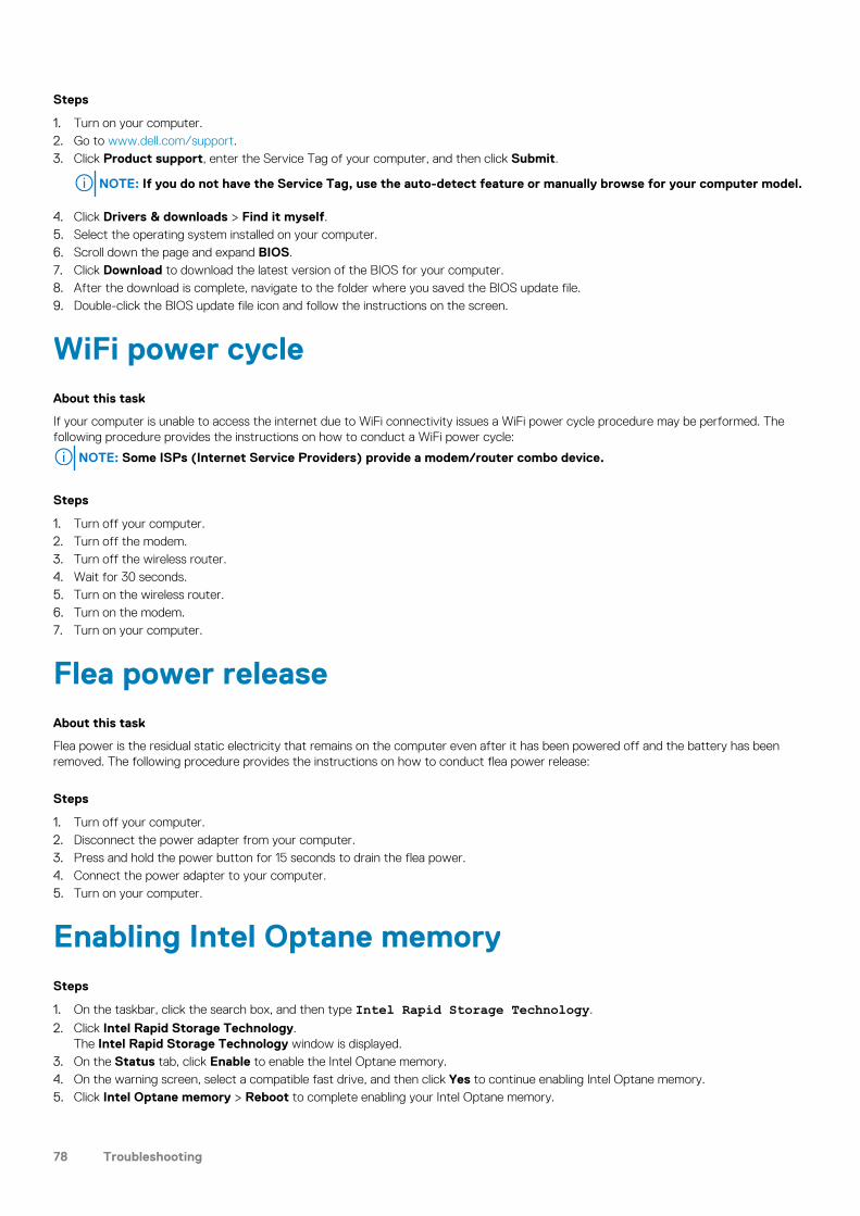
Steps
1. Turn on your computer.2. Go to www.dell.com/support.3. Click Product support, enter the Service Tag of your computer, and then click Submit.
NOTE: If you do not have the Service Tag, use the auto-detect feature or manually browse for your computer model.
4. Click Drivers & downloads > Find it myself.5. Select the operating system installed on your computer.6. Scroll down the page and expand BIOS.7. Click Download to download the latest version of the BIOS for your computer.8. After the download is complete, navigate to the folder where you saved the BIOS update file.9. Double-click the BIOS update file icon and follow the instructions on the screen.
WiFi power cycleAbout this task
If your computer is unable to access the internet due to WiFi connectivity issues a WiFi power cycle procedure may be performed. Thefollowing procedure provides the instructions on how to conduct a WiFi power cycle:
NOTE: Some ISPs (Internet Service Providers) provide a modem/router combo device.
Steps
1. Turn off your computer.2. Turn off the modem.3. Turn off the wireless router.4. Wait for 30 seconds.5. Turn on the wireless router.6. Turn on the modem.7. Turn on your computer.
Flea power releaseAbout this task
Flea power is the residual static electricity that remains on the computer even after it has been powered off and the battery has beenremoved. The following procedure provides the instructions on how to conduct flea power release:
Steps
1. Turn off your computer.2. Disconnect the power adapter from your computer.3. Press and hold the power button for 15 seconds to drain the flea power.4. Connect the power adapter to your computer.5. Turn on your computer.
Enabling Intel Optane memorySteps
1. On the taskbar, click the search box, and then type Intel Rapid Storage Technology.
2. Click Intel Rapid Storage Technology.The Intel Rapid Storage Technology window is displayed.
3. On the Status tab, click Enable to enable the Intel Optane memory.4. On the warning screen, select a compatible fast drive, and then click Yes to continue enabling Intel Optane memory.5. Click Intel Optane memory > Reboot to complete enabling your Intel Optane memory.
78 Troubleshooting
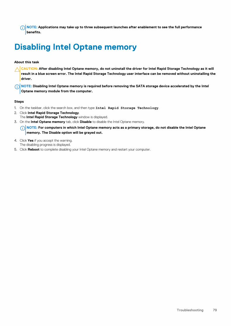
NOTE: Applications may take up to three subsequent launches after enablement to see the full performance
benefits.
Disabling Intel Optane memory
About this task
CAUTION: After disabling Intel Optane memory, do not uninstall the driver for Intel Rapid Storage Technology as it will
result in a blue screen error. The Intel Rapid Storage Technology user interface can be removed without uninstalling the
driver.
NOTE: Disabling Intel Optane memory is required before removing the SATA storage device accelerated by the Intel
Optane memory module from the computer.
Steps
1. On the taskbar, click the search box, and then type Intel Rapid Storage Technology.
2. Click Intel Rapid Storage Technology.The Intel Rapid Storage Technology window is displayed.
3. On the Intel Optane memory tab, click Disable to disable the Intel Optane memory.
NOTE: For computers in which Intel Optane memory acts as a primary storage, do not disable the Intel Optane
memory. The Disable option will be grayed out.
4. Click Yes if you accept the warning.The disabling progress is displayed.
5. Click Reboot to complete disabling your Intel Optane memory and restart your computer.
Troubleshooting 79
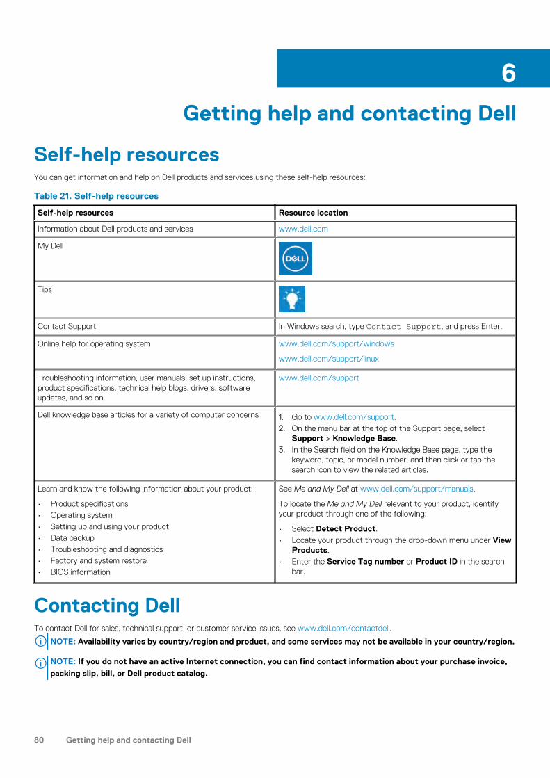
Getting help and contacting Dell
Self-help resourcesYou can get information and help on Dell products and services using these self-help resources:
Table 21. Self-help resources
Self-help resources Resource location
Information about Dell products and services www.dell.com
My Dell
Tips
Contact Support In Windows search, type Contact Support, and press Enter.
Online help for operating system www.dell.com/support/windows
www.dell.com/support/linux
Troubleshooting information, user manuals, set up instructions,product specifications, technical help blogs, drivers, softwareupdates, and so on.
www.dell.com/support
Dell knowledge base articles for a variety of computer concerns 1. Go to www.dell.com/support.2. On the menu bar at the top of the Support page, select
Support > Knowledge Base.3. In the Search field on the Knowledge Base page, type the
keyword, topic, or model number, and then click or tap thesearch icon to view the related articles.
Learn and know the following information about your product:
• Product specifications• Operating system• Setting up and using your product• Data backup• Troubleshooting and diagnostics• Factory and system restore• BIOS information
See Me and My Dell at www.dell.com/support/manuals.
To locate the Me and My Dell relevant to your product, identifyyour product through one of the following:
• Select Detect Product.• Locate your product through the drop-down menu under View
Products.• Enter the Service Tag number or Product ID in the search
bar.
Contacting DellTo contact Dell for sales, technical support, or customer service issues, see www.dell.com/contactdell.
NOTE: Availability varies by country/region and product, and some services may not be available in your country/region.
NOTE: If you do not have an active Internet connection, you can find contact information about your purchase invoice,
packing slip, bill, or Dell product catalog.
6
80 Getting help and contacting Dell
![Index [editorial.mcpressonline.com]editorial.mcpressonline.com/web/mcpdf.nsf/wdocs/5090/$FILE/5090… · Application Developer, IBM Certified Application Developer – DB2 9 Family,](https://img.dokumen.tips/doc/110x75/5f2f0f9c825e3001bb1db9e4/index-file5090-application-developer-ibm-certified-application-developer.jpg)