Embed Size (px)
Citation preview

190-00577-03 October 2007 Revision C
G1000 System Maintenance
Manual Columbia 350/400


G1000-Columbia 350/400 System Maintenance Manual Page A 190-00577-03 Revision C
© Copyright 2005-2007 Garmin Ltd. Or its subsidiaries
All Rights Reserved
Except as expressly provided herein, no part of this manual may be reproduced, copied, transmitted, disseminated, downloaded or stored in any storage medium, for any purpose without the express prior written consent of Garmin. Garmin hereby grants permission to download a single copy of this manual and of any revision to this manual onto a hard drive or other electronic storage medium to be viewed and to print one copy of this manual or of any revision hereto, provided that such electronic or printed copy of this manual or revision must contain the complete text of this copyright notice and provided further that any unauthorized commercial distribution of this manual or any revision hereto is strictly prohibited.
Garmin International, Inc. 1200 E. 151st Street
Olathe, KS 66062 USA Telephone: 913.397.8200
www.garmin.com
Garmin (Europe) Ltd. Liberty House
Bull Copse Road Hounsdown Business Park
Southampton, SO40 9RB, UK Telephone: 44(0) 8708501241
RECORD OF REVISIONS
Revision Revision Date Description 1 12/14/05 Initial Release 2 1/16/06 Updated servo torque checks and fuel calibration
procedures. A 2/13/07 Revised the GDC 74A test procedure. B 9/13/07 Improved troubleshooting in section 4, updated software
loading for V8.X in section 6 along with updated servo torque checks.
C 10/19/07 Updated for WAAS configuration; removed statement “WAAS is currently not an FAA approved or available configuration” throughout section 6. Also added the GCU 476 Boot Block Upgrade procedure to section 6. Throughout document changed statements with the label IMPORTANT to read NOTE. Added a note to page 5-9 about the system ID changing when master config module is replaced.
Page B G1000-Columbia 350/400 System Maintenance Manual Revision C 190-00577-03
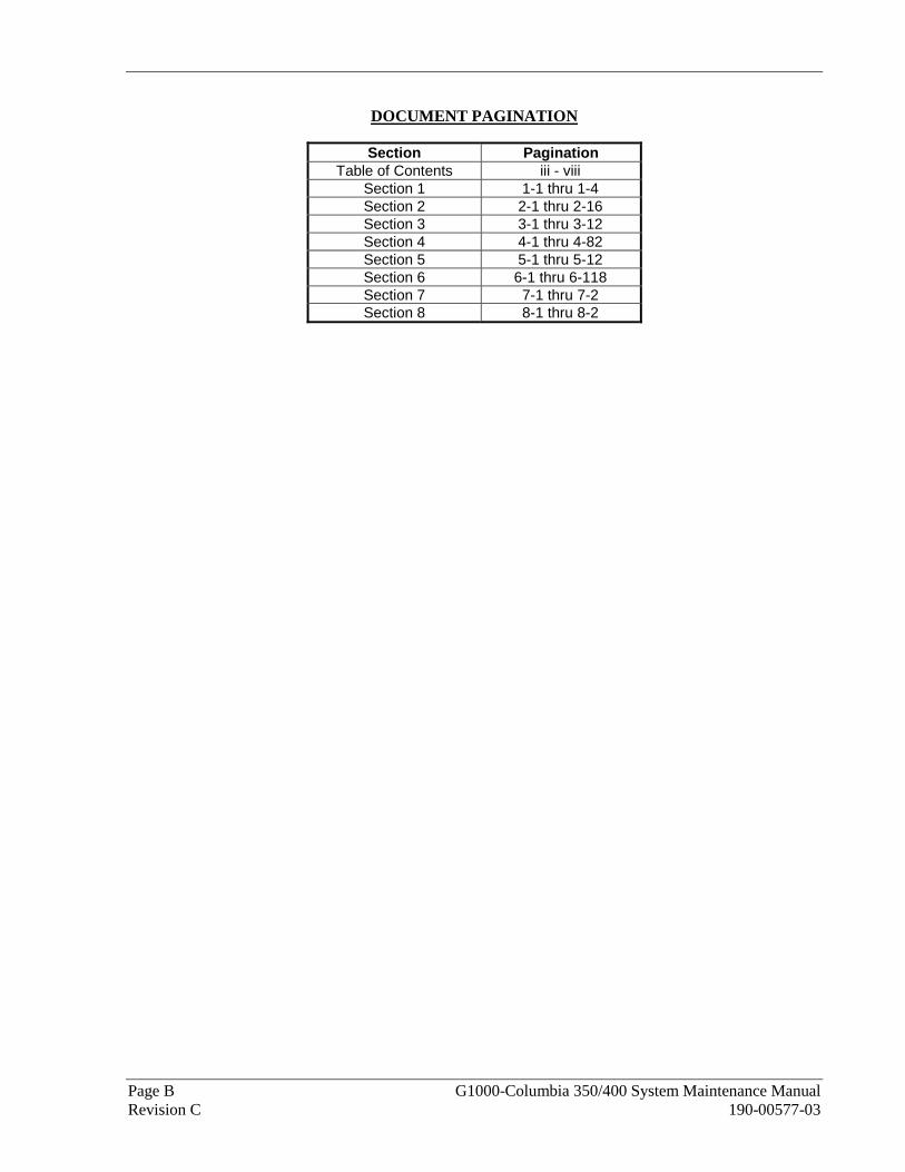
DOCUMENT PAGINATION
Section Pagination Table of Contents iii - viii
Section 1 1-1 thru 1-4 Section 2 2-1 thru 2-16 Section 3 3-1 thru 3-12 Section 4 4-1 thru 4-82 Section 5 5-1 thru 5-12 Section 6 6-1 thru 6-118 Section 7 7-1 thru 7-2 Section 8 8-1 thru 8-2

G1000-Columbia 350/400 System Maintenance Manual Page i 190-00577-03 Revision C
INFORMATION SUBJECT TO EXPORT CONTROL LAWS
This document may contain information which is subject to the Export Administration Regulations ("EAR") issued by the United States Department of Commerce (15 CFR, Chapter VII, Subchapter C) and which may not be exported, released, or disclosed to foreign nationals inside or outside of the United States without first obtaining an export license. A violation of the EAR may be subject to a penalty of up to 10 years imprisonment and a fine of up to $1,000,000 under Section 2410 of the Export Administration Act of 1979. Include this notice with any reproduced portion of this document.
WARNING
This product, its packaging, and its components contain chemicals known to the State of California to cause cancer, birth defects, or reproductive harm. This Notice is being provided in accordance with California's Proposition 65. If you have any questions or would like additional information, please refer to our web site at www.garmin.com/prop65.
CAUTION
The GDU 1040 and 1042 use a lens coated with a special anti-reflective coating that is very sensitive to skin oils, waxes and abrasive cleaners. CLEANERS CONTAINING AMMONIA WILL HARM THE ANTI-REFLECTIVE COATING. It is very important to clean the lens using a clean, lint-free cloth and an eyeglass lens cleaner that is specified as safe for anti-reflective coatings.
CAUTION
All G1000 screen shots used in this document are current at the time of publication. Screen shots are intended to provide visual reference only. All information depicted in screen shots, including software file names, versions and part numbers, is subject to change and may not be up to date.

Page ii G1000-Columbia 350/400 System Maintenance Manual Revision C 190-00577-03
This Page Intentionally Left Blank
G1000-Columbia 350/400 System Maintenance Manual Page iii 190-00577-03 Revision C
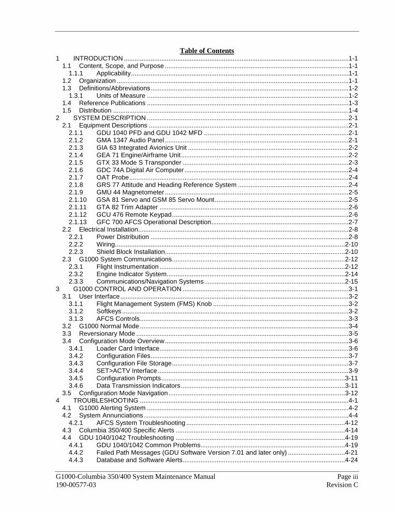
Table of Contents 1 INTRODUCTION ..............................................................................................................................1-1
1.1 Content, Scope, and Purpose .......................................................................................................1-1 1.1.1 Applicability..........................................................................................................................1-1
1.2 Organization ..................................................................................................................................1-1 1.3 Definitions/Abbreviations...............................................................................................................1-2
1.3.1 Units of Measure .................................................................................................................1-2 1.4 Reference Publications .................................................................................................................1-3 1.5 Distribution ....................................................................................................................................1-4
2 SYSTEM DESCRIPTION .................................................................................................................2-1 2.1 Equipment Descriptions ................................................................................................................2-1
2.1.1 GDU 1040 PFD and GDU 1042 MFD .................................................................................2-1 2.1.2 GMA 1347 Audio Panel .......................................................................................................2-1 2.1.3 GIA 63 Integrated Avionics Unit ..........................................................................................2-2 2.1.4 GEA 71 Engine/Airframe Unit..............................................................................................2-2 2.1.5 GTX 33 Mode S Transponder .............................................................................................2-3 2.1.6 GDC 74A Digital Air Computer ............................................................................................2-4 2.1.7 OAT Probe...........................................................................................................................2-4 2.1.8 GRS 77 Attitude and Heading Reference System ..............................................................2-4 2.1.9 GMU 44 Magnetometer .......................................................................................................2-5 2.1.10 GSA 81 Servo and GSM 85 Servo Mount...........................................................................2-5 2.1.11 GTA 82 Trim Adapter ..........................................................................................................2-6 2.1.12 GCU 476 Remote Keypad...................................................................................................2-6 2.1.13 GFC 700 AFCS Operational Description.............................................................................2-7
2.2 Electrical Installation......................................................................................................................2-8 2.2.1 Power Distribution ...............................................................................................................2-8 2.2.2 Wiring.................................................................................................................................2-10 2.2.3 Shield Block Installation.....................................................................................................2-10
2.3 G1000 System Communications.................................................................................................2-12 2.3.1 Flight Instrumentation ........................................................................................................2-12 2.3.2 Engine Indicator System....................................................................................................2-14 2.3.3 Communications/Navigation Systems...............................................................................2-15
3 G1000 CONTROL AND OPERATION .............................................................................................3-1 3.1 User Interface................................................................................................................................3-2
3.1.1 Flight Management System (FMS) Knob ............................................................................3-2 3.1.2 Softkeys ...............................................................................................................................3-2 3.1.3 AFCS Controls.....................................................................................................................3-3
3.2 G1000 Normal Mode .....................................................................................................................3-4 3.3 Reversionary Mode .......................................................................................................................3-5 3.4 Configuration Mode Overview.......................................................................................................3-6
3.4.1 Loader Card Interface..........................................................................................................3-6 3.4.2 Configuration Files...............................................................................................................3-7 3.4.3 Configuration File Storage...................................................................................................3-7 3.4.4 SET>ACTV Interface...........................................................................................................3-9 3.4.5 Configuration Prompts.......................................................................................................3-11 3.4.6 Data Transmission Indicators............................................................................................3-11
3.5 Configuration Mode Navigation...................................................................................................3-12 4 TROUBLESHOOTING .....................................................................................................................4-1
4.1 G1000 Alerting System .................................................................................................................4-2 4.2 System Annunciations...................................................................................................................4-4
4.2.1 AFCS System Troubleshooting .........................................................................................4-12 4.3 Columbia 350/400 Specific Alerts ...............................................................................................4-14 4.4 GDU 1040/1042 Troubleshooting ...............................................................................................4-19
4.4.1 GDU 1040/1042 Common Problems.................................................................................4-19 4.4.2 Failed Path Messages (GDU Software Version 7.01 and later only) ................................4-21 4.4.3 Database and Software Alerts...........................................................................................4-24

Page iv G1000-Columbia 350/400 System Maintenance Manual Revision C 190-00577-03
4.4.4 GDU Cooling Alerts ...........................................................................................................4-27 4.4.5 Key Alerts ..........................................................................................................................4-28 4.4.6 Datacard Alerts..................................................................................................................4-28 4.4.7 Miscellaneous Alerts..........................................................................................................4-28
4.5 GMA 1347 ...................................................................................................................................4-34 4.5.2 Common Problems............................................................................................................4-36 4.5.3 GMA Alerts ........................................................................................................................4-37 4.5.4 Backup Path Alerts ............................................................................................................4-38
4.6 GIA 63 .........................................................................................................................................4-39 4.6.1 Configuration Pages ..........................................................................................................4-39 4.6.2 COM ..................................................................................................................................4-45 4.6.3 GPS ...................................................................................................................................4-46 4.6.4 NAV ...................................................................................................................................4-46 4.6.5 G/S.....................................................................................................................................4-47 4.6.6 COM Related Alerts...........................................................................................................4-47 4.6.7 NAV Related Alerts............................................................................................................4-49 4.6.8 G/S Related Alerts.............................................................................................................4-50 4.6.9 GPS Related Alerts ...........................................................................................................4-50 4.6.10 GIA Cooling Alerts .............................................................................................................4-51 4.6.11 Other GIA Alerts ................................................................................................................4-51
4.7 GEA Troubleshooting ..................................................................................................................4-53 4.7.1 GEA 71 Configuration Pages ............................................................................................4-53 4.7.2 Common Problems............................................................................................................4-55 4.7.3 GEA 71 Related Alerts ......................................................................................................4-55 4.7.4 Backup Path Alerts ............................................................................................................4-56
4.8 GTX Troubleshooting ..................................................................................................................4-57 4.8.1 GTX 33 Common Alerts ....................................................................................................4-57 4.8.2 Backup Path Alerts ............................................................................................................4-58
4.9 GRS 77 /GMU 44 ........................................................................................................................4-59 4.9.1 Configuration Pages ..........................................................................................................4-59 4.9.2 Common Problems............................................................................................................4-60 4.9.3 Common Alerts..................................................................................................................4-61 4.9.4 Backup Path Alerts ............................................................................................................4-62 4.9.5 GMU Related Alerts...........................................................................................................4-63
4.10 GDC 74A .....................................................................................................................................4-63 4.10.1 Common Problems............................................................................................................4-63 4.10.2 GDC 74A Related Alerts....................................................................................................4-63 4.10.3 Backup Path Alerts ............................................................................................................4-64
4.11 GDL 69/69A Configuration Pages...............................................................................................4-65 4.11.1 GDL 69 Page.....................................................................................................................4-65 4.11.2 Common Problems............................................................................................................4-67 4.11.3 GDL 69/69A Related Alerts ...............................................................................................4-68 4.11.4 GCU 476 Troubleshooting.................................................................................................4-69
4.12 GFC 700......................................................................................................................................4-70 4.12.1 Configuration Pages ..........................................................................................................4-70 4.12.2 GFC 700 Pre-Flight Test Sequence and Troubleshooting ................................................4-72
4.13 Backshell Connectors..................................................................................................................4-79 5 G1000 EQUIPMENT REMOVAL AND REPLACEMENT.................................................................5-1
5.1 GDU 1040 PFD/GDU 1042 MFD ..................................................................................................5-2 5.2 GMA 1347 Audio Panel.................................................................................................................5-2 5.3 GIA 63 Integrated Avionics Units ..................................................................................................5-2 5.4 GEA 71 Engine/Airframe Unit .......................................................................................................5-3 5.5 GTX 33 Transponder.....................................................................................................................5-3 5.6 GDC 74A Air Data Computer ........................................................................................................5-3 5.7 GTP 59 OAT Probe .......................................................................................................................5-4 5.8 GRS 77 AHRS...............................................................................................................................5-4

G1000-Columbia 350/400 System Maintenance Manual Page v 190-00577-03 Revision C
5.9 GMU 44 Magnetometer.................................................................................................................5-4 5.10 GDL 69A Data Link .......................................................................................................................5-5 5.11 GCU 476........................................................................................................................................5-5 5.12 GSA 81 Autopilot Roll Servo .........................................................................................................5-5 5.13 GSM 85 Autopilot Roll Servo Mount .............................................................................................5-6 5.14 GSA 81 Autopilot Pitch Servo .......................................................................................................5-6 5.15 GSM 85 Autopilot Pitch Servo Mount............................................................................................5-7 5.16 GTA 82 Pitch Trim.........................................................................................................................5-7 5.17 GSM Slip Clutch Adjustment Procedure .......................................................................................5-7 5.18 Configuration Module Removal and Replacement .......................................................................5-8 5.19 GEA 71 Backshell Thermocouple Removal and Replacement...................................................5-10
6 G1000 EQUIPMENT CONFIGURATION AND TESTING................................................................6-1 6.1 GDU 1040 PFD/GDU 1042 MFD ..................................................................................................6-1
6.1.1 PFD/MFD Software Loading using GDU V6.XX .................................................................6-1 6.1.2 PFD/MFD Configuration using GDU V6.XX ........................................................................6-2 6.1.3 MFD & PFD software loading and Configuration using GDU V8.XX ..................................6-5 6.1.4 Aviation Database Loading..................................................................................................6-5 6.1.5 PFD/MFD Test.....................................................................................................................6-6
6.2 GMA 1347 Audio Panel.................................................................................................................6-8 6.2.1 GMA 1347 Software Loading using GDU V6.XX ................................................................6-8 6.2.2 GMA 1347 Configuration using GDU V6.XX.......................................................................6-9 6.2.3 GMA 1347 Software Load and Configuration using GDU V8.XX......................................6-10 6.2.4 GMA 1347 Test .................................................................................................................6-14
6.3 GIA 63 Integrated Avionics Unit ..................................................................................................6-15 6.3.1 GIA 63 Software Loading using GDU V6.XX ....................................................................6-15 6.3.2 GIA 63 Configuration using GDU V6.XX...........................................................................6-18 6.3.3 GIA 63 Certification Gain Loading.....................................................................................6-19 6.3.4 GIA 63 Software Load and Configuration using GDU V8.XX............................................6-20 6.3.5 GIA 63 Test .......................................................................................................................6-23
6.4 GEA 71 Engine/Airframe Unit .....................................................................................................6-25 6.4.1 GEA 71 Software Loading using GDU V6.XX...................................................................6-25 6.4.2 GEA 71 Configuration Loading using GDU V6.XX............................................................6-27 6.4.3 GEA 71 Software Load and Configuration using GDU V8.XX ..........................................6-28 6.4.4 GEA 71 Calibration using GDU V6.XX..............................................................................6-31 6.4.5 GEA 71 Calibration using GDU V8.XX..............................................................................6-34 6.4.6 Aileron and Elevator Trim Calibration................................................................................6-39 6.4.7 GEA 71 Test ......................................................................................................................6-41
6.5 GTX 33 Transponder...................................................................................................................6-43 6.5.1 GTX 33 Software Loading using GDU V6.XX ...................................................................6-43 6.5.2 GTX 33 Configuration Loading using GDU V6.XX............................................................6-44 6.5.3 GTX 33 Software Load and Configuration using GDU V8.XX ..........................................6-46 6.5.4 GTX 33 Test ......................................................................................................................6-49
6.6 GDC 74A Air Data Computer ......................................................................................................6-50 6.6.1 GDC 74A Software Loading using GDU V6.XX ................................................................6-50 6.6.2 GDC 74A Configuration Loading using GDU V6.XX.........................................................6-51 6.6.3 GDC 74A Software Load and Configuration using GDU V8.XX .......................................6-52 6.6.4 GDC 74A Test ...................................................................................................................6-55
6.7 GRS 77 AHRS / GMU 44 Magnetometer....................................................................................6-57 6.7.1 GRS 77 Software Loading using GDU V6.XX...................................................................6-57 6.7.2 GMU 44 Software Loading using GDU V6.XX ..................................................................6-58 6.7.3 GRS 77 / GMU 44 Software Load and Configuration using GDU V8.XX .........................6-60 6.7.4 GRS/GMU Calibration .......................................................................................................6-63 6.7.5 GRS/GMU Test .................................................................................................................6-71 6.7.6 GRS 77 Earth Magnetic Field Updates .............................................................................6-71
6.8 GDL 69A Data Link .....................................................................................................................6-72 6.8.1 GDL 69A Software Loading using GDU V6.XX.................................................................6-72

Page vi G1000-Columbia 350/400 System Maintenance Manual Revision C 190-00577-03
6.8.2 GDL 69A Configuration Loading using GDU V6.XX .........................................................6-73 6.8.3 GDL 69A Software Load and Configuration using GDU V8.XX........................................6-74 6.8.4 GDL 69A Test....................................................................................................................6-77
6.9 GSA 81 Autopilot Servos/GTA 82 Pitch Trim Adapter ................................................................6-78 6.9.1 GSA 81 Servo Software Loading using GDU V6.XX ........................................................6-78 6.9.2 GTA 82 Pitch Trim Adapter Software Loading using GDU V6.XX ....................................6-80 6.9.3 GIA 63, GSA 81 and GTA 82 Certification Gain Loading using GDU V6.XX....................6-82 6.9.4 Servo Software Load and Configuration using GDU V8.XX .............................................6-84
6.10 GFC 700 Autopilot Ground Checks.............................................................................................6-87 6.10.1 Autopilot Pre-Flight Test ....................................................................................................6-87 6.10.2 AFCS Switch Checks ........................................................................................................6-88 6.10.3 Autopilot Clutch Overpower Check ...................................................................................6-89 6.10.4 Manual Electric Trim Speed Check ...................................................................................6-89 6.10.5 Autopilot Operation Checks...............................................................................................6-89 6.10.6 Servo Torque Limit Validation ...........................................................................................6-90
6.11 GCU 476 Remote Keypad...........................................................................................................6-93 6.11.1 GCU 476 Software Upload using GDU V6.XX..................................................................6-93 6.11.2 GCU 476 Configuration Loading using GDU V6.XX .........................................................6-94 6.11.3 GCU 476 Software Load and Configuration using GDU V8.XX........................................6-96 6.11.4 GCU 476 Boot Block Upgrade ..........................................................................................6-98
6.12 Optional Systems ......................................................................................................................6-100 6.12.1 Enabling TAWS using GDU V6.XX .................................................................................6-100 6.12.2 TAWS Activation using GDU V8.XX................................................................................6-101 6.12.3 ChartView ........................................................................................................................6-102 6.12.4 Oxygen System using GDU V6.XX .................................................................................6-103 6.12.5 Oxygen System using GDU V8.XX .................................................................................6-104 6.12.6 WX-500 Stormscope Configuration using GDU V6.XX...................................................6-106 6.12.7 WX-500 Stormscope using GDU V8.XX .........................................................................6-108 6.12.8 Ryan 9900BX TCAD Configuration using GDU V6.XX ...................................................6-109 6.12.9 Ryan 9900BX TCAD Configuration using GDU V8.XX ...................................................6-111
6.13 Complete G1000 software load using GDU V8.XX...................................................................6-112 6.14 Software/Configuration Troubleshooting...................................................................................6-116
6.14.1 System Communication Hierarchy ..................................................................................6-117 7 SYSTEM RETURN TO SERVICE PROCEDURE............................................................................7-1
7.1 GIA Failure Test ............................................................................................................................7-1 7.2 Display Failure Test.......................................................................................................................7-2 7.3 AHRS/ADC Backup Path Test ......................................................................................................7-2 7.4 Maintenance Records ...................................................................................................................7-2
8 REQUIRED EQUIPMENT ................................................................................................................8-1 8.1 G1000 Required Equipment..........................................................................................................8-1 8.2 Weight & Balance..........................................................................................................................8-1
List of Figures
Figure 2-1. G1000/350/400 Display Configuration....................................................................................2-1 Figure 2-2. GIA 63 Integrated Avionics Unit..............................................................................................2-2 Figure 2-3. GEA 71 Engine/Airframe Unit .................................................................................................2-2 Figure 2-4. GTX 33 Mode S Transponder.................................................................................................2-3 Figure 2-5. GDC 74A Air Data Computer..................................................................................................2-4 Figure 2-6. GRS 77 AHRS ........................................................................................................................2-4 Figure 2-7. GMU 44 Magnetometer ..........................................................................................................2-5 Figure 2-8. GSA 81 Servo and GSM 85 Servo Mount ..............................................................................2-5 Figure 2-9. GTA 82 Pitch Trim Adapter.....................................................................................................2-6 Figure 2-10. GCU 476 ...............................................................................................................................2-6 Figure 2-11. Power Distribution.................................................................................................................2-9 Figure 2-12. Shield Block Installation to Backshell (78-pin Connector Example) ...................................2-10 Figure 2-13. G1000 System Interface .....................................................................................................2-12
G1000-Columbia 350/400 System Maintenance Manual Page vii 190-00577-03 Revision C
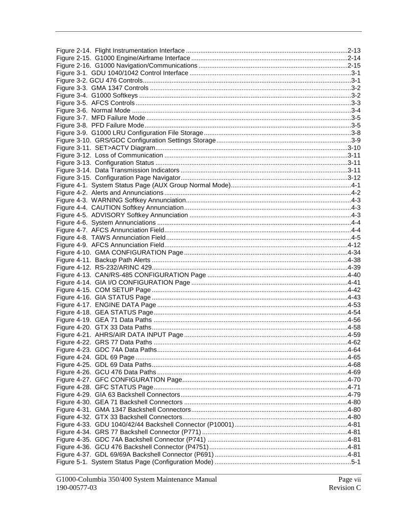
Figure 2-14. Flight Instrumentation Interface ..........................................................................................2-13 Figure 2-15. G1000 Engine/Airframe Interface .......................................................................................2-14 Figure 2-16. G1000 Navigation/Communications ...................................................................................2-15 Figure 3-1. GDU 1040/1042 Control Interface ..........................................................................................3-1 Figure 3-2. GCU 476 Controls....................................................................................................................3-1 Figure 3-3. GMA 1347 Controls ................................................................................................................3-2 Figure 3-4. G1000 Softkeys ......................................................................................................................3-2 Figure 3-5. AFCS Controls ........................................................................................................................3-3 Figure 3-6. Normal Mode ..........................................................................................................................3-4 Figure 3-7. MFD Failure Mode ..................................................................................................................3-5 Figure 3-8. PFD Failure Mode...................................................................................................................3-5 Figure 3-9. G1000 LRU Configuration File Storage..................................................................................3-8 Figure 3-10. GRS/GDC Configuration Settings Storage...........................................................................3-9 Figure 3-11. SET>ACTV Diagram...........................................................................................................3-10 Figure 3-12. Loss of Communication ......................................................................................................3-11 Figure 3-13. Configuration Status ...........................................................................................................3-11 Figure 3-14. Data Transmission Indicators .............................................................................................3-11 Figure 3-15. Configuration Page Navigator.............................................................................................3-12 Figure 4-1. System Status Page (AUX Group Normal Mode)...................................................................4-1 Figure 4-2. Alerts and Annunciations ........................................................................................................4-2 Figure 4-3. WARNING Softkey Annunciation............................................................................................4-3 Figure 4-4. CAUTION Softkey Annunciation.............................................................................................4-3 Figure 4-5. ADVISORY Softkey Annunciation ..........................................................................................4-3 Figure 4-6. System Annunciations ............................................................................................................4-4 Figure 4-7. AFCS Annunciation Field........................................................................................................4-4 Figure 4-8. TAWS Annunciation Field.......................................................................................................4-5 Figure 4-9. AFCS Annunciation Field......................................................................................................4-12 Figure 4-10. GMA CONFIGURATION Page ...........................................................................................4-34 Figure 4-11. Backup Path Alerts .............................................................................................................4-38 Figure 4-12. RS-232/ARINC 429.............................................................................................................4-39 Figure 4-13. CAN/RS-485 CONFIGURATION Page ..............................................................................4-40 Figure 4-14. GIA I/O CONFIGURATION Page .......................................................................................4-41 Figure 4-15. COM SETUP Page .............................................................................................................4-42 Figure 4-16. GIA STATUS Page .............................................................................................................4-43 Figure 4-17. ENGINE DATA Page ..........................................................................................................4-53 Figure 4-18. GEA STATUS Page............................................................................................................4-54 Figure 4-19. GEA 71 Data Paths ............................................................................................................4-56 Figure 4-20. GTX 33 Data Paths.............................................................................................................4-58 Figure 4-21. AHRS/AIR DATA INPUT Page ...........................................................................................4-59 Figure 4-22. GRS 77 Data Paths ............................................................................................................4-62 Figure 4-23. GDC 74A Data Paths..........................................................................................................4-64 Figure 4-24. GDL 69 Page ......................................................................................................................4-65 Figure 4-25. GDL 69 Data Paths.............................................................................................................4-68 Figure 4-26. GCU 476 Data Paths ..........................................................................................................4-69 Figure 4-27. GFC CONFIGURATION Page............................................................................................4-70 Figure 4-28. GFC STATUS Page............................................................................................................4-71 Figure 4-29. GIA 63 Backshell Connectors.............................................................................................4-79 Figure 4-30. GEA 71 Backshell Connectors ...........................................................................................4-80 Figure 4-31. GMA 1347 Backshell Connectors.......................................................................................4-80 Figure 4-32. GTX 33 Backshell Connectors............................................................................................4-80 Figure 4-33. GDU 1040/42/44 Backshell Connector (P10001)...............................................................4-81 Figure 4-34. GRS 77 Backshell Connector (P771) .................................................................................4-81 Figure 4-35. GDC 74A Backshell Connector (P741) ..............................................................................4-81 Figure 4-36. GCU 476 Backshell Connector (P4751).............................................................................4-81 Figure 4-37. GDL 69/69A Backshell Connector (P691) ..........................................................................4-81 Figure 5-1. System Status Page (Configuration Mode) ............................................................................5-1
Page viii G1000-Columbia 350/400 System Maintenance Manual Revision C 190-00577-03
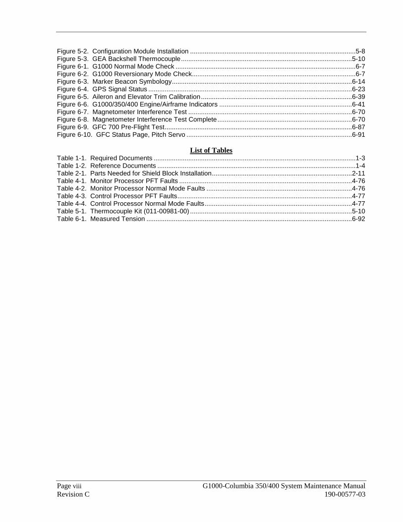
Figure 5-2. Configuration Module Installation ...........................................................................................5-8 Figure 5-3. GEA Backshell Thermocouple..............................................................................................5-10 Figure 6-1. G1000 Normal Mode Check ...................................................................................................6-7 Figure 6-2. G1000 Reversionary Mode Check..........................................................................................6-7 Figure 6-3. Marker Beacon Symbology...................................................................................................6-14 Figure 6-4. GPS Signal Status ................................................................................................................6-23 Figure 6-5. Aileron and Elevator Trim Calibration...................................................................................6-39 Figure 6-6. G1000/350/400 Engine/Airframe Indicators .........................................................................6-41 Figure 6-7. Magnetometer Interference Test ..........................................................................................6-70 Figure 6-8. Magnetometer Interference Test Complete..........................................................................6-70 Figure 6-9. GFC 700 Pre-Flight Test.......................................................................................................6-87 Figure 6-10. GFC Status Page, Pitch Servo ...........................................................................................6-91
List of Tables Table 1-1. Required Documents ...............................................................................................................1-3 Table 1-2. Reference Documents .............................................................................................................1-4 Table 2-1. Parts Needed for Shield Block Installation.............................................................................2-11 Table 4-1. Monitor Processor PFT Faults ...............................................................................................4-76 Table 4-2. Monitor Processor Normal Mode Faults ................................................................................4-76 Table 4-3. Control Processor PFT Faults................................................................................................4-77 Table 4-4. Control Processor Normal Mode Faults.................................................................................4-77 Table 5-1. Thermocouple Kit (011-00981-00) .........................................................................................5-10 Table 6-1. Measured Tension .................................................................................................................6-92

G1000-Columbia 350/400 System Maintenance Manual Page 1-1 190-00577-03 Revision C
1 INTRODUCTION
1.1 Content, Scope, and Purpose This document provides information for field maintenance of the Garmin G1000 Integrated Cockpit Avionics Suite as installed in the Columbia 350/400. This document is required by the Instructions for Continued Airworthiness, 190-00577-01, to perform continued airworthiness maintenance on the installation. Use the information presented in the manual in conjunction with required documents shown in Table 1-1.
1.1.1 Applicability
This document applies to all 350/400 aircraft equipped with the G1000 Integrated Cockpit Avionics Suite installed.
1.2 Organization The following outline briefly describes the organization of this manual:
Section 2: System Description
Provides a complete description of the type design change associated with installing the G1000 integrated cockpit system in the Columbia 350/400. An overview of the electrical systems and G1000 system interface is also provided.
Section 3: G1000 Control & Operation
Presents basic control and operation information specifically tailored to maintenance practices. Basic G1000 Configuration Mode operation is also described.
Section 4: Troubleshooting
Provides troubleshooting information to aid in diagnosing and resolving potential problems with the G1000 system.
Section 5: G1000 Equipment Removal & Replacement
Gives instructions for the removal and replacement of G1000 equipment.
Section 6: G1000 Equipment Configuration & Testing
Gives instructions for loading software, configuring, and testing of G1000 equipment.
Section 7: System Return to Service Procedure
Specifies return-to-service procedures to be performed upon completion of maintenance of the G1000 system.
Section 8: Required Equipment
Provides part number for the latest revision of the Required Equipment List. The list will provide the specific code loader part number, software part number, and software version.
Appendix A: Full G1000 Software/Configuration Procedure
Provides a complete software/configuration loading procedure in cases where the G1000 system as a whole requires complete software/configuration update or reload.

Page 1-2 G1000-Columbia 350/400 System Maintenance Manual Revision C 190-00577-03
1.3 Definitions/Abbreviations ADI: Attitude Display Indicator
AHRS: Attitude Heading Reference System
AMM: Airplane Maintenance Manual
CDU: Control Display Unit
CFR: Code of Federal Regulations
EAU: Engine/Airframe Unit
EIS: Engine Instrumentation Systems
HIRF: High Intensity Radiated Fields
HSDB: High-Speed Data Bus (Ethernet)
IAU: Integrated Avionics Unit
ICS: Inter-Com System
LRU: Line Replaceable Unit
MFD: Multi-Function Flight Display
OAT: Outside Air Temperature
PFD: Primary Flight Display
STC: Supplemental Type Certificate
S/W: Software
TC: Type Certificate
TSO: Technical Standard Order
TVS: Transient Voltage Suppressor
VHF: Very High Frequency
1.3.1 Units of Measure
Unless otherwise stated, all units of measure are English units.

G1000-Columbia 350/400 System Maintenance Manual Page 1-3 190-00577-03 Revision C
1.4 Reference Publications The following documents are required in addition to this maintenance manual to perform maintenance:
Table 1-1. Required Documents
Document Part Number Vendor
G1000/350/400 Required Equipment List RB011002 CAM (Columbia Aircraft Manufacturing)
G1000 Cockpit Reference Guide for the Columbia 350/400 190-00567-00 Garmin
G1000 Cockpit Reference Guide for the Columbia 350/400 (updated for GDU V8.XX software)
190-00567-01 Garmin
Columbia 350 (G1000) Pilot’s Operating Handbook and FAA Approved AFM
RB050005 CAM
Columbia 400 (G1000) Pilot’s Operating Handbook and FAA Approved AFM
RC050005 CAM
Columbia 350 Airplane Maintenance Manual RB050002F CAM
Columbia 400 Airplane Maintenance Manual RC050001C CAM

Page 1-4 G1000-Columbia 350/400 System Maintenance Manual Revision C 190-00577-03
The following documents provide additional information above and beyond the scope of this document. The part numbers are Garmin part numbers unless otherwise noted.
Table 1-2. Reference Documents
Document Part Number
Airplane Electrical Manual, Columbia 350 RB24009 [1]
Airplane Electrical Manual, Columbia 400 RC24008 [1]
G1000 Software Loading and Post Installation Checkout Columbia 350/400 190-00577-02
G1000 V8.XX Software Loading and Post Installation Checkout Columbia 350/400
190-00577-04
G1000 Configuration Manual 190-00303-04
Aircraft Fastener Assembly Torque 005-00249-00
Aircraft Contact and Terminal Crimping 005-00249-01
Heat Shrink Tubing Application 005-00249-02
Aircraft Soldering 005-00249-03
G1000 System Installation Manual 190-00303-00
GDU 104X Installation Manual 190-00303-01
GMA 1347 Installation Manual 190-00303-20
GIA 63 Installation Manual 190-00303-05
GEA 71 Installation Manual 190-00303-40
GDC 74A Installation Manual 190-00303-15
GRS 77 /GMU 44 Installation Manual 190-00303-10
GTX 33 Installation Manual 190-00303-61
GDL 69/69A Installation Manual 190-00355-02
GSA/GSM 8X Installation Manual 190-00303-72
GCU 47X Installation Manual 190-00303-75
GTA 82 Installation Manual 190-00303-74
GDL 69/69A XM™ Satellite Radio Activation Instructions 190-00355-04
[1] Columbia Aircraft Manufacturing P/N
1.5 Distribution This document is to be a permanent aircraft record and is distributed with a new G1000-equipped Columbia 350/400 aircraft. Revisions to this document will be made by Garmin and will be distributed by Garmin per standard documentation revision procedures.

G1000-Columbia 350/400 System Maintenance Manual Page 2-1 190-00577-03 Revision C
2 SYSTEM DESCRIPTION The G1000 integrated cockpit is installed in the Columbia 350/400 using the equipment listed in this section.
Structures in the Columbia 350/400 must be modified and/or installed per drawing located in the Airplane Electrical Manual, part number RB240009 (Columbia 350) or part number RC240008 (Columbia 400).
NOTE
The Airplane Electrical Manual, part number RB240009 (Columbia 350) or RC240008 (Columbia 400) contains drawings that support the system description and aid in G1000 system installation awareness.
2.1 Equipment Descriptions
2.1.1 GDU 1040 PFD and GDU 1042 MFD
Figure 2-1. G1000/350/400 Display Configuration
Two Garmin GDUs are installed in the 350/400 instrument panel. The PFD is a GDU 1040 and the MFD is a GDU 1042. Both displays provide control and display of nearly all functions of the G1000 integrated cockpit system. The displays are located side-by-side, with the GMA 1347 Audio Panel located in the middle.
Both displays are installed in the instrument panel using built-in ¼-turn fasteners. Each display uses a single Garmin 62-pin connector. Electrical power to the PFD is from the essential bus, whereas the MFD receives power from the Avionics bus.
On the panel, traditional attitude, altitude, and airspeed indicators are provided as backup instruments. These are mounted in a vertical configuration to the right of the MFD.
2.1.2 GMA 1347 Audio Panel
The Garmin GMA 1347 Audio Panel is a digital audio panel with integrated marker beacon receiver. The GMA 1347 provides control of all cockpit intercom/mic systems as well as NAV/COM/ILS audio. The unit also provides display reversion mode control through a large red button. Power is received from the Avionics bus; consequently the unit only powers up when the avionics master switch is turned on. The GMA 1347 interfaces with the existing marker beacon antenna as well as existing mic and phone jacks.
Page 2-2 G1000-Columbia 350/400 System Maintenance Manual Revision C 190-00577-03
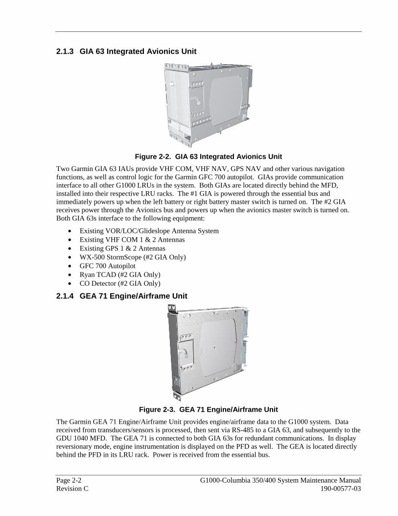
2.1.3 GIA 63 Integrated Avionics Unit
Figure 2-2. GIA 63 Integrated Avionics Unit
Two Garmin GIA 63 IAUs provide VHF COM, VHF NAV, GPS NAV and other various navigation functions, as well as control logic for the Garmin GFC 700 autopilot. GIAs provide communication interface to all other G1000 LRUs in the system. Both GIAs are located directly behind the MFD, installed into their respective LRU racks. The #1 GIA is powered through the essential bus and immediately powers up when the left battery or right battery master switch is turned on. The #2 GIA receives power through the Avionics bus and powers up when the avionics master switch is turned on. Both GIA 63s interface to the following equipment:
• Existing VOR/LOC/Glideslope Antenna System • Existing VHF COM 1 & 2 Antennas • Existing GPS 1 & 2 Antennas • WX-500 StormScope (#2 GIA Only) • GFC 700 Autopilot • Ryan TCAD (#2 GIA Only) • CO Detector (#2 GIA Only)
2.1.4 GEA 71 Engine/Airframe Unit
Figure 2-3. GEA 71 Engine/Airframe Unit
The Garmin GEA 71 Engine/Airframe Unit provides engine/airframe data to the G1000 system. Data received from transducers/sensors is processed, then sent via RS-485 to a GIA 63, and subsequently to the GDU 1040 MFD. The GEA 71 is connected to both GIA 63s for redundant communications. In display reversionary mode, engine instrumentation is displayed on the PFD as well. The GEA is located directly behind the PFD in its LRU rack. Power is received from the essential bus.

G1000-Columbia 350/400 System Maintenance Manual Page 2-3 190-00577-03 Revision C
2.1.4.1 Engine/Airframe Sensors
The GEA interfaces to the following:
The following equipment, systems and sensors interface to the G1000 avionics systems:
• Existing Manifold Pressure Sensor • Existing Tachometer Sensor • Existing Oil Pressure Sensor And Low Pressure Switch • Existing Oil Temperature Sensor • Existing Cylinder Head Temperature (CHT) Sensors • Exhaust Gas Temperature (EGT) Sensors • Existing Turbine Inlet Temperature (TIT) Sensors (Columbia 400 only) • Existing Fuel Level Sensors (Four) • Existing Low Fuel Switches (L And R) • Existing Fuel Selector Position Switches • Existing Fuel Flow Sensor • Existing Electrical System Sensors And Alternator Inoperative Switches • Existing Open Door Detection Switch • Existing Aileron And Elevator Position Sensors • Existing Oxygen System Sensors And Switches • Existing Starter Engage System
2.1.5 GTX 33 Mode S Transponder
Figure 2-4. GTX 33 Mode S Transponder
The Garmin GTX 33 provides Mode A, C, and S altitude and position reporting information from the G1000 system. The unit is mounted directly behind the PFD in its LRU rack. Power is received from the Avionics Bus. The GTX 33 sends data via RS-232 directly to a GIA 63. Information is then sent to the PFD, where the pilot can control the transponder. The GTX 33 is connected to both GIA 63s for redundant communications. The GTX 33 interfaces with the existing transponder antenna.
Page 2-4 G1000-Columbia 350/400 System Maintenance Manual Revision C 190-00577-03
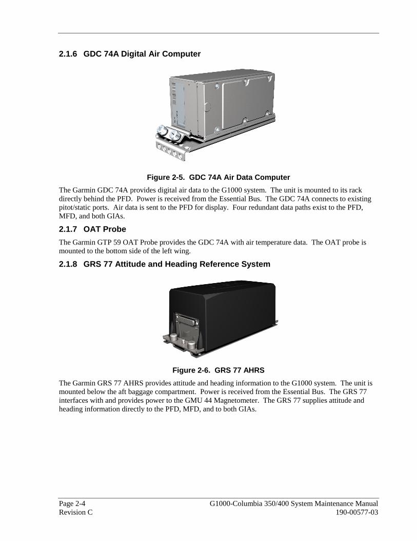
2.1.6 GDC 74A Digital Air Computer
Figure 2-5. GDC 74A Air Data Computer
The Garmin GDC 74A provides digital air data to the G1000 system. The unit is mounted to its rack directly behind the PFD. Power is received from the Essential Bus. The GDC 74A connects to existing pitot/static ports. Air data is sent to the PFD for display. Four redundant data paths exist to the PFD, MFD, and both GIAs.
2.1.7 OAT Probe
The Garmin GTP 59 OAT Probe provides the GDC 74A with air temperature data. The OAT probe is mounted to the bottom side of the left wing.
2.1.8 GRS 77 Attitude and Heading Reference System
Figure 2-6. GRS 77 AHRS
The Garmin GRS 77 AHRS provides attitude and heading information to the G1000 system. The unit is mounted below the aft baggage compartment. Power is received from the Essential Bus. The GRS 77 interfaces with and provides power to the GMU 44 Magnetometer. The GRS 77 supplies attitude and heading information directly to the PFD, MFD, and to both GIAs.

G1000-Columbia 350/400 System Maintenance Manual Page 2-5 190-00577-03 Revision C
2.1.9 GMU 44 Magnetometer
Figure 2-7. GMU 44 Magnetometer
The GMU 44 provides horizontal and vertical magnetic field information to the GRS 77 AHRS. This allows heading to be calculated and provides assistance during AHRS alignment. The GMU 44 is mounted at the left wingtip.
2.1.10 GSA 81 Servo and GSM 85 Servo Mount
Figure 2-8. GSA 81 Servo and GSM 85 Servo Mount
The GSA 81 is mated to the GSM 85 Servo Mount to form a single servo unit. There are two servo units in this installation:
• Pitch • Roll
The design of the servo assembly allows the servo portion (GSA 81) to be removed from the capstan (GSM 85) without the need to de-rig the aircraft control cables. The roll servo is located beneath the rear passenger seats, and the pitch servo is located beneath the aft baggage area.

Page 2-6 G1000-Columbia 350/400 System Maintenance Manual Revision C 190-00577-03
2.1.11 GTA 82 Trim Adapter
Figure 2-9. GTA 82 Pitch Trim Adapter
The Garmin GTA 82 Trim Adapter is a remote mounted device that is used to allow the GFC 700 to drive a pitch trim actuator provided by the airframe manufacturer. The GTA 82 adapter is located under the instrument panel on the pilot side beneath the standby instruments. The trim adapter is powered by the Essential Bus and interfaces with two GIA 63 Integrated Avionics units through serial communication on separate RS-485 ports.
2.1.12 GCU 476 Remote Keypad
Figure 2-10. GCU 476
The GCU 476 interfaces with the GDU 104x PFD/MFD. The GCU 476 Remote Keypad provides alphanumeric, softkey, and flight planning function keys used to interface with the G1000. In addition to alphanumeric, softkey, and flight planning function keys the GCU 476 provides COM/NAV tuning capabilities. The GCU 476 mounts on the center console using a single jackscrew.

G1000-Columbia 350/400 System Maintenance Manual Page 2-7 190-00577-03 Revision C
2.1.13 GFC 700 AFCS Operational Description
The GFC 700 is a two-axis fail-safe digital flight control system. There is no single LRU with the name “GFC 700;” rather “GFC 700” refers to an integrated autopilot and flight director system, with functions provided by multiple G1000 LRUs and servos. The following functions are provided by the GFC 700 in this installation:
• Flight Director • Autopilot • Manual Electric Trim
Flight Director:
The Flight Director operates within the #1 GIA 63 and uses data from the G1000 system, including air data, attitude, and navigation data, to calculate commands for display to the pilot and for the Autopilot. Flight Director command bars and mode annunciations are sent to the PFD through a high-speed Ethernet connection for display to the pilot. The Flight Director operates independently of the Autopilot, and allows the pilot to hand-fly the command bars, if desired.
Autopilot:
The Autopilot operates within the four GSA 81 servos. Flight Director data is processed within the four servos and turned into aircraft flight control surface commands. The Autopilot cannot operate unless the Flight Director is engaged.
The following is a summary of the autopilot functions provided by each LRU:
• GDU 1040 PFD – Displays the Flight Director command bars and the autopilot mode annunciations.
• GDU 1042 MFD – Provides controls for the autopilot functions. • GIA 63 – Performs the calculations to display the Flight Director command bars on the PFD and
sends control movement commands to the GSA 81 autopilot servos. • GSA 81 – Actuates the control surfaces based on commands received from the GIA 63. • GTA 82 – Actuates the elevator trim.

Page 2-8 G1000-Columbia 350/400 System Maintenance Manual Revision C 190-00577-03
2.2 Electrical Installation
2.2.1 Power Distribution
Distribution of power to the G1000 system occurs on four aircraft electrical buses. See Figure 2-11 for diagram.
Left Bus: The left bus is tied directly to the aircraft left battery (battery 1) via the left battery master switch. When the left battery master switch is turned on, power is immediately supplied to the left bus. The left bus will also receive power from the right bus when the cross tie relay is closed. The cross tie relay is operated by the switch in the overhead console.
Right Bus: The right bus is tied directly to the right battery via the right battery master switch. When the right battery master switch is turned on, power is immediately supplied to the right bus. The right bus will also receive power from the left bus when the cross tie relay is closed. The cross tie relay is operated by the switch in the overhead console.
Essential Bus: The essential bus is diode-fed from the left and right buses. When either the left or right battery master switch is turned on, power is immediately supplied to the essential bus.
Avionics Bus: The Avionics bus is tied to the left and right bus via the avionics master switch.

G1000-Columbia 350/400 System Maintenance Manual Page 2-9 190-00577-03 Revision C
Figure 2-11. Power Distribution

Page 2-10 G1000-Columbia 350/400 System Maintenance Manual Revision C 190-00577-03
2.2.2 Wiring
A wiring harness is fabricated and installed according to the wiring diagrams provided in the applicable and latest revision of the 350/400 electrical manual.
2.2.3 Shield Block Installation
Most G1000 connectors employ a shield block grounding system to provide necessary ground reference to shielding and/or transducers.
Figure 2-12. Shield Block Installation to Backshell (78-pin Connector Example)

G1000-Columbia 350/400 System Maintenance Manual Page 2-11 190-00577-03 Revision C
Table 2-1. Parts Needed for Shield Block Installation
Figure Ref Description GPN or MIL spec 1 Cast Housing (from Garmin Backshell Kit) 125-0008x-00
2 Shield Block(s) 117-00147-00 117-00147-01
3 Screw,4-40x.250,FLHP 100,SS/P,Nylon (from Garmin Shield Block Kit) 211-63234-08
4 Multiple Conductor Shielded Cable (2 –conductor demonstrated here)
Reference Installation Wiring Diagrams
5 Drain Wire Shield Termination (method optional)
Parts used depend on method chosen
(see page 7 and 8) 6 Braid, Flat (19-20 AWG equivalent, tinned
plated copper strands 36 AWG, Circular Mil Area 1000 -1300)
Parts used depend on method chosen
7 Floating Shield Termination (method optional)
Parts used depend on method chosen
(see page 8) 8 Pins 336-00021-00
Ring terminal, #8, insulated, 18-22 AWG MS25036-149 Ring terminal, #8, insulated, 14-16 AWG MS25036-153 9 Ring terminal, #8, insulated, 10-12 AWG MS25036-156 Screw, PHP, 8-32x.312", Stainless MS51957-42
10 Screw, PHP, 8-32x.312", Cad Plated Steel
MS35206-242
Split Washer, #8, (.045" compressed thickness) Stainless MS35338-137
11 Split Washer, #8, (.045" compressed thickness) Cad-plated steel MS35338-42
Flat Washer, Stainless, #8, .032" thick, .174"ID, .375" OD NAS1149CN832R
12 Flat washer, Cad-plated Steel, #8, .032" thick, .174"ID, .375" OD NAS1149FN832P
13 Silicon Fusion Tape 249-00114-00 14 Strain Relief (from Garmin Backshell Kit) 115-00499-xx
15 Screw,4-40x.375,PHP,SS/P,w/Nylon (from Garmin Backshell Kit) 211-60234-10
16 Lid from Garmin Backshell Kit 115-00500-xx
17 Screw,4-40x.187,FLHP100,SS/P,w/Nylon (from Garmin Backshell Kit) 211-63234-06

Page 2-12 G1000-Columbia 350/400 System Maintenance Manual Revision C 190-00577-03
2.3 G1000 System Communications
Figure 2-13. G1000 System Interface
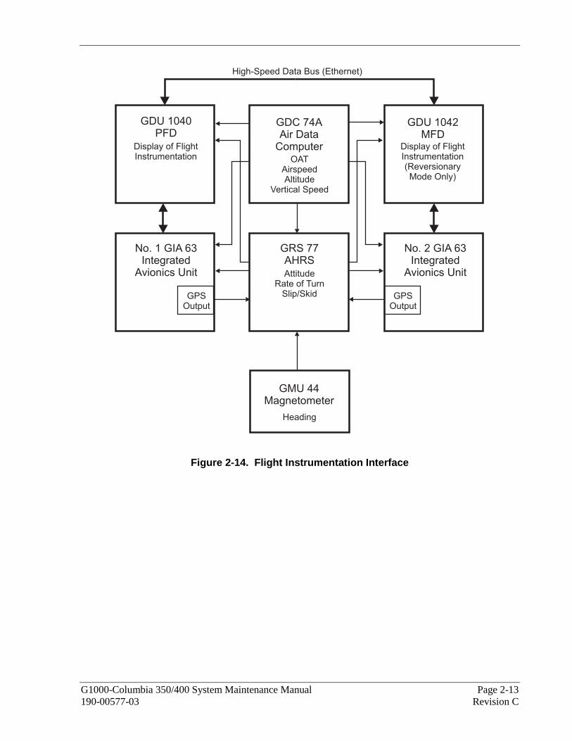
2.3.1 Flight Instrumentation
The GRS 77 AHRS, GDC 74A Air Data Computer, and GMU 44 Magnetometer are responsible for providing the G1000 system with flight instrumentation (refer to Figure 2-14). Data consists of aircraft attitude, heading, altitude, airspeed, vertical speed, and outside air temperature information, all displayed on the PFD (data is displayed on the MFD in reversionary mode only).
Primary data outputs from the GRS and GDC are sent directly to the PFD via ARINC 429. Secondary data paths connect the GRS and GDC to the MFD. Additional communications paths connect the GRS and GDC to both GIA 63 units, providing quadruple redundant interface.
The GRS 77 receives GPS data from both GIAs, airspeed data from the GDC, and magnetic heading from the GMU. Using these three external sources, combined with internal sensor data, the GRS accurately calculates aircraft attitude and heading.
G1000-Columbia 350/400 System Maintenance Manual Page 2-13 190-00577-03 Revision C
No. 1 GIA 63Integrated
Avionics Unit
No. 2 GIA 63Integrated
Avionics Unit
GDU 1040PFD
Display of FlightInstrumentation
GDC 74AAir Data
ComputerOAT
AirspeedAltitude
Vertical Speed
GDU 1042MFD
Display of FlightInstrumentation(ReversionaryMode Only)
GRS 77AHRSAttitude
Rate of TurnSlip/Skid
GMU 44Magnetometer
Heading
High-Speed Data Bus (Ethernet)
GPSOutput
GPSOutput
Figure 2-14. Flight Instrumentation Interface

Page 2-14 G1000-Columbia 350/400 System Maintenance Manual Revision C 190-00577-03
2.3.2 Engine Indicator System
The GEA 71 provides engine/airframe data to the G1000 system. The unit interfaces to transducers shown in Figure 2-15. Analog data is received from the transducers and is converted to a digital signal by the GEA 71. Digital information is then sent through the primary RS-485 serial path to the #1 GIA 63. From the GIA, data is sent through the HSDB connection to the PFD, then on to the MFD for display. A backup data path from the GEA to the #2 GIA 63, then on to the MFD, exists in the event the primary path fails.
No. 1 GIA 63
IntegratedAvionics Unit
GEA 71
Engine/AirframeUnit
No. GIA 632Integrated
Avionics Unit
GDU 1042MFD
Display ofEngine/Airframe
Instruments
High-Speed Data Bus (Ethernet)
GDU 1040PFD
Display ofEngine/Airframe
Instruments(Reversionary Mode Only)
Engine/AirframeTransducers:
RPM, Manifold Pressure, Oil Pressure,Oil Temperature, CHT/EGT, TIT, Fuel Flow,
Fuel Quantity, Fuel Low Discretes, Fuel SelectorValve Position, Bus Volts, Starter Engaged System,
Battery Current, Alternator Current, Low Oil PressureDiscrete, Aileron Trim Position, Elevator Trim Position,Oxygen Pressure, Alternator Inop, Door Open Discrete
Figure 2-15. G1000 Engine/Airframe Interface

G1000-Columbia 350/400 System Maintenance Manual Page 2-15 190-00577-03 Revision C
2.3.3 Communications/Navigation Systems
The GIA 63 IAUs contain VHF COM, VHF NAV, and GPS receivers. COM and NAV audio is sent via digital audio to the GMA 1347 Audio Panel.
GPS information is sent to the GRS 77 AHRS and to both displays for processing.
The GTX 33 Mode S Transponder communicates with both GIAs. Transponder data is sent from the GIAs to the PFD where control and operation occurs.
The GMA 1347 Audio Panel controls the display reversionary mode.
No. 1 GIA 63Integrated
Avionics Unit
No. 2 GIA 63Integrated
Avionics Unit
GDU 1040PFD
Control & Display Of:COM/NAV Radios
Transponder InterfaceVarious Navigational Functions
GMA 1347Audio Panel
Reversionary Control
GDU 1042MFD
Control & Display Of:COM/NAV Radios
Various Navigational Functions
Transponder Interface(Reversionary Mode Only)
GTX 33Mode S
Transponder
High-Speed Data Bus (Ethernet)
Digital COM/NAV AudioVoice Alerts
Marker BeaconIntercom Control
Digital Audio Control
Digital COM/NAV AudioVoice Alerts
VHF COMVHF NAV/LOC
GPSGlideslope
Various I/O Processors
VHF COMVHF NAV/LOC
GPSGlideslope
Various I/O Processors
Course/Heading DatumSelected AltitudeHSI Output Signals
To Autopilot
Figure 2-16. G1000 Navigation/Communications

Page 2-16 G1000-Columbia 350/400 System Maintenance Manual Revision C 190-00577-03
This Page Intentionally Left Blank
G1000-Columbia 350/400 System Maintenance Manual Page 3-1 190-00577-03 Revision C
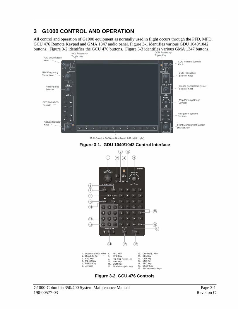
3 G1000 CONTROL AND OPERATION All control and operation of G1000 equipment as normally used in flight occurs through the PFD, MFD, GCU 476 Remote Keypad and GMA 1347 audio panel. Figure 3-1 identifies various GDU 1040/1042 buttons. Figure 3-2 identifies the GCU 476 buttons. Figure 3-3 identifies various GMA 1347 buttons.
COM Frequency
Toggle Key
COM Frequency
Selector Knob
Course (Inner)/Baro (Outer)
Selector Knob
Map Panning/Range
Joystick
Navigation Systems
Controls
Flight Management System
(FMS) Knob
Multi-Function Softkeys (Numbered 1-12, left to right)
NAV Frequency
Toggle Key
NAV Frequency
Tuner Knob
Heading Bug
Selector
NAV Volume/Ident
Knob
Altitude Selector
Knob
COM Volume/Squelch
Knob
GFC 700 AFCS
Controls
Figure 3-1. GDU 1040/1042 Control Interface
1 2
3
4
5
6
7
8
9
10
19
11
12
13
14 15 16
17
18
1. Dual FMS/NAV Knob2. Direct-To Key3. FPL Key4. MENU Key5. PROC Key6. Joystick
7. PFD Key8. MFD Key
9. Flip-Flop Key ( )
10. NAV Key11. COM Key12. Plus/Minus (+/-) Key
← →← →
13. Decimal (.) Key14. SEL Key15. CLR Key16. ENT Key17. SPC Key18. BKSP Key19. Alphanumeric Keys
Figure 3-2. GCU 476 Controls

Page 3-2 G1000-Columbia 350/400 System Maintenance Manual Revision C 190-00577-03
Transmitters
Split COM
Passenger Address
Marker Beacon/Mute
Navigation Radio Audio
Manual Squelch
Volume/SquelchControl
Transceiver Audio
Cellular Telephone
Speaker
Marker Beacon Signal Sensitivity
Navigation Radio Audio
Digital Recording Playback
ICS Isolation
Display BackupReversionary Button
Figure 3-3. GMA 1347 Controls 3.1 User Interface
3.1.1 Flight Management System (FMS) Knob
The FMS knob is the primary control for the G1000 system. Operation is similar to the Garmin 400/500 Series units.
• To cycle through different configuration screens: To change page groups: Rotate the large FMS knob. To change pages in a group: Rotate the small FMS knob.
• To activate the cursor for a page, press the small FMS knob directly in, as one would push a regular button.
• To cycle the cursor through different data fields, rotate the large FMS knob. • To change the contents of a highlighted data field, rotate the small FMS knob. This action either
brings up an options menu for the particular field, or in some cases allows the operator to enter data for the field.
• To confirm a selection, press the ENT key. • To cancel a selection, press the small FMS knob in again, deactivating the cursor. The CLR key
may also be used to cancel a selection.
3.1.2 Softkeys
Some pages have commands or selections that are activated by the GDU 1040/1042 softkeys. If a softkey is associated with a command, that command will be displayed directly above the key. A grayed-out softkey shows a command that is unavailable. A softkey that is highlighted shows the current active selection.
Figure 3-4. G1000 Softkeys

G1000-Columbia 350/400 System Maintenance Manual Page 3-3 190-00577-03 Revision C
3.1.3 AFCS Controls
The dedicated AFCS controls on the GDU 1042 are discussed in detail in the G1000 Cockpit Reference Guide for the Columbia 350/400, P/N 190-00567-00. The following figure is provided for reference.
Heading Mode Key
Approach Mode Key
NOSE UP Key
NOSE DN Key
Autopilot Key
Flight Director Key
Navigation Mode Key
Altitude Hold Mode Key
Vertical Speed Mode Key
Flight Level Change Mode Key
Figure 3-5. AFCS Controls
Page 3-4 G1000-Columbia 350/400 System Maintenance Manual Revision C 190-00577-03
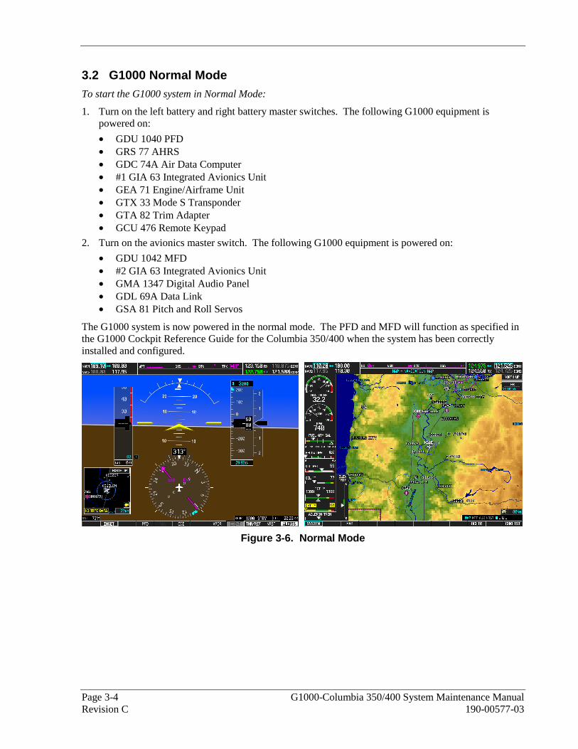
3.2 G1000 Normal Mode To start the G1000 system in Normal Mode:
1. Turn on the left battery and right battery master switches. The following G1000 equipment is powered on:
• GDU 1040 PFD • GRS 77 AHRS • GDC 74A Air Data Computer • #1 GIA 63 Integrated Avionics Unit • GEA 71 Engine/Airframe Unit • GTX 33 Mode S Transponder • GTA 82 Trim Adapter • GCU 476 Remote Keypad
2. Turn on the avionics master switch. The following G1000 equipment is powered on:
• GDU 1042 MFD • #2 GIA 63 Integrated Avionics Unit • GMA 1347 Digital Audio Panel • GDL 69A Data Link • GSA 81 Pitch and Roll Servos
The G1000 system is now powered in the normal mode. The PFD and MFD will function as specified in the G1000 Cockpit Reference Guide for the Columbia 350/400 when the system has been correctly installed and configured.
Figure 3-6. Normal Mode

G1000-Columbia 350/400 System Maintenance Manual Page 3-5 190-00577-03 Revision C
3.3 Reversionary Mode Should a display communication or hardware failure occur, the G1000 system automatically enters the reversionary mode. The system reversionary mode forces the remaining display into showing all information related to safe flight.
A manual reversionary mode also allows the operator to force the system into reversionary mode in situations where the system does not automatically enter reversionary mode. A large red button on the GMA 1347 audio panel activates the manual reversionary mode.
Figure 3-7. MFD Failure Mode
Should the PFD display fail, the MFD automatically enters reversionary mode. In this mode, flight- critical information from the AHRS/Air Data system is displayed on the MFD along with essential engine instrumentation.
Figure 3-8. PFD Failure Mode

Page 3-6 G1000-Columbia 350/400 System Maintenance Manual Revision C 190-00577-03
3.4 Configuration Mode Overview The Configuration Mode exists to provide the technician with a means of configuring, checking, and calibrating various G1000 sub-systems. Troubleshooting and diagnostics information can also be viewed in this mode.
To start the system in Configuration Mode:
1. Start the system in normal mode as described in Section 3.2.
2. Remove power to the PFD and MFD by pulling the circuit breakers labeled PFD and MFD.
3. Press and hold the ENT key on the PFD while applying power using the PFD circuit breaker.
4. Release the ENT key after ‘INITIALIZING SYSTEM’ appears in the upper left corner of the PFD.
5. Power on the MFD in the same manner. It is best to have both displays in Configuration Mode whenever performing post-installation practices.
CAUTION
The Configuration Mode contains certain pages and settings that are critical to aircraft operation and safety. Such pages are protected and cannot be modified, unless the technician is properly authorized and equipped. However, most protected pages are viewable to allow system awareness for troubleshooting.
NOTE
For a complete description and breakdown of each Configuration Mode page, refer to the G1000 Configuration Manual, Garmin part number 190-00303-04.
3.4.1 Loader Card Interface
The G1000 Code Loader Card interface exists to provide a means of loading software and configuration files to the system and LRUs. The G1000-Columbia 350/400 Code Loader Cards use a 128 MB Secure Digital (SD) data card that contains:
• All G1000 LRU Software Files
• All G1000 Configuration Files
All software and configuration files were pre-determined by Garmin and/or Columbia during design of the system. During removal and replacement of LRUs, software and configuration files may need to be reloaded (See Sections 5 & 6). To satisfy TC requirements for the Columbia 350/400, it is critical that the technician uses the correct G1000-Columbia 350/400 Code Loader Card part number when servicing the G1000 system.
The G1000-Columbia 350/400 Code Loader Card part number defines all files specific to the G1000 system as installed in the Columbia 350/400. Approved Loader Card part numbers for the 350/400 can be found in the Required Equipment List, Columbia P/N RB011002.
CAUTION
Always use caution when using Code Loader Cards during maintenance. The G1000 system is designed to immediately initialize the card upon power-up. On-screen prompts must be given careful attention in order to avoid potential loss of data. Always read through procedures given in Sections 4, 5, 6, and/or Required Equipment List before attempting to use the Code Loader Cards.

G1000-Columbia 350/400 System Maintenance Manual Page 3-7 190-00577-03 Revision C
3.4.2 Configuration Files
A G1000-Columbia 350/400 Code Loader Card typically contains the following configuration files:
• AIRFRAME: This file contains data such as airspeed parameters, engine/airframe sensor limitations, fuel tank parameters and alerting system settings that tailor a G1000 PFD or MFD to the 350/400.
• SYSTEM: This file configures the G1000 Ethernet to expect a PFD, MFD, and two GIAs.
• MANIFEST: This file loads a manifest of all software part numbers and versions associated with an approved system configuration.
• MFD1: This file configures MFD serial/discrete communication and alert system settings. • PFD1: This file configures PFD serial/discrete communication and alert system settings.
• GIA1/GIA2: These files configure GIA1/GIA2 serial/discrete communication settings.
• GMA1: This file configures GMA 1347 audio and serial communication settings. • GTX1: This file configures GTX 33 transponder and serial communications settings.
• GEA1: This file configures GEA 71 engine/airframe parameters.
• GDC1: This file configures GDC 74A air data values for the 350/400. • GDL69: This file configures the GDL 69A data link settings.
• GCU476: This file configures the GCU 476. • CALIBRATION: This file configures the fuel calibration data.
• AUDIO CONFIGURATION: This file configures the audio settings. The above files are loaded during the configuration processes listed in Section 6. Each file is sent directly to the applicable LRU. The same file is also stored in PFD internal configuration memory. The PFD also sends a copy of all configuration files to its connector configuration module. If the PFD is replaced, the configuration module retains all configuration files in the aircraft.
NOTE
The GRS 77 AHRS and GMU 44 Magnetometer do not utilize a configuration file. However, these LRUs do require several calibrations during installation checkout to tailor sensor characteristics to a specific 350/400 airframe. While performing maintenance on these units, re-calibration may be required. See Section 6.7.4 for more information on re-calibration criteria.
3.4.3 Configuration File Storage
The G1000 system is designed to store all configuration settings in various places so that the configuration is retained in the aircraft during maintenance of units. Figure 3-9 and Figure 3-10 illustrate where the various configuration files are stored.

Page 3-8 G1000-Columbia 350/400 System Maintenance Manual Revision C 190-00577-03
Master configuration module contains identicalbackup configuration files of PFD configurationmemory.
PFD cross-checks these backup files against filescontained within PFD memory. PFD self configuresto match master configuration module.
(Located in PFD backshell connector)
G1000 Master Configuration Module
GDU 1040PFD
Contains ‘ACTIVE’ PFD settingsRepresents ‘SET’ column for all LRUsStores all configuration files in internalmemory.Uses master configuration module forbackup.
Contains ‘ACTIVE’ GMAsettings.
Uses PFD Internalconfiguration files forbackup.
GMA 1347Audio Panel
Contains ‘ACTIVE’ MFD settings
The MFD uses PFD internalconfiguration files for backup.
GDU 1042MFD
No. 1 GIA 63
Contains ‘ACTIVE’ configuration settings internally.
GIA 1 uses PFD internal configuration files forbackup.
No. 2 GIA 63
Contains ‘ACTIVE’ configuration settings internally.
GIA 2 uses PFD internal configuration files forbackup.
GEA 71
Contains ‘ACTIVE’ configuration settings internally.
The GEA 71 configuration module is NOT used forconfiguration settings.
The GEA 71 uses PFD internal configurationfiles for backup.
High-Speed Data Bus (Ethernet)
RS
-23
2
RS
-48
5R
S-2
32
RS
-48
5
GTX 33
Contains ‘ACTIVE’ transponder settings internally.
The GTX 33 uses PFD internal configurationfiles for backup.
RS
-48
5
RS
-48
5
GCU 476
Contains ‘ACTIVE’ configuration settings internally.GCU 476 uses PFD internal configuration files forbackup.
RS
-23
2
RS
-23
2
Figure 3-9. G1000 LRU Configuration File Storage
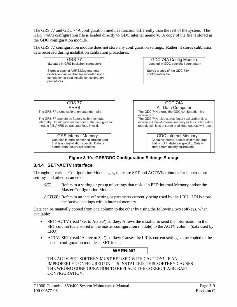
G1000-Columbia 350/400 System Maintenance Manual Page 3-9 190-00577-03 Revision C
The GRS 77 and GDC 74A configuration modules function differently than the rest of the system. The GDC 74A’s configuration file is loaded directly to GDC internal memory. A copy of the file is stored in the GDC configuration module.
The GRS 77 configuration module does not store any configuration settings. Rather, it stores calibration data recorded during installation calibration procedures.
GRS 77(Located in GRS backshell connector)
Stores a copy of AHRS/Magnetometercalibration values that are recorded uponcompletion of post installation calibrationprocedures.
GDC 74A Config Module(Located in GDC backshell connector)
Stores a copy of the GDC 74Aconfiguration file.
GRS 77AHRS
The GRS 77 stores calibration data internally.
The GRS 77 also stores factory calibration datainternally. Should internal memory or the configurationmodule fail, AHRS output data flags invalid.
GRS Internal MemoryContains internal sensor calibration datathat is not installation specific. Data isstored from factory calibrations.
GDC 74AAir Data Computer
The GDC 74A stores the GDC configuration fileinternally.The GDC 74A also stores factory calibration datainternally. Should internal memory or the configurationmodule fail, loss of some or all data outputs will result.
GDC Internal MemoryContains internal sensor calibration datathat is not installation specific. Data isstored from factory calibrations.
Figure 3-10. GRS/GDC Configuration Settings Storage
3.4.4 SET>ACTV Interface
Throughout various Configuration Mode pages, there are SET and ACTIVE columns for input/output settings and other parameters.
SET: Refers to a setting or group of settings that reside in PFD Internal Memory and/or the Master Configuration Module.
ACTIVE: Refers to an ‘active’ setting or parameter currently being used by the LRU. LRUs store the ‘active’ settings within internal memory.
Data can be manually copied from one column to the other by using the following two softkeys, when available:
• SET>ACTV (read ‘Set to Active’) softkey: Allows the installer to send the information in the SET column (data stored in the master configuration module) to the ACTV column (data used by LRU).
• ACTV>SET (read ‘Active to Set’) softkey: Causes the LRUs current settings to be copied to the master configuration module as SET items.
WARNING
THE ACTV>SET SOFTKEY MUST BE USED WITH CAUTION! IF AN IMPROPERLY CONFIGURED UNIT IS INSTALLED, THIS SOFTKEY CAUSES THE WRONG CONFIGURATION TO REPLACE THE CORRECT AIRCRAFT CONFIGURATION!

Page 3-10 G1000-Columbia 350/400 System Maintenance Manual Revision C 190-00577-03
In the first example shown in Figure 3-11, the SET columns do not match the ACTIVE columns. The inequality between SET and ACTIVE indicates a configuration mismatch. By pressing the SET>ACTV softkey, this copies the SET column to the LRU unit’s configuration memory. The settings then become the ACTIVE settings for the LRU being configured.
Configuration MismatchMaster Configuration Module
≠
LRU Memory Master Configuration Module
≠
LRU Memory
SET>ACTV Softkey
Master Configuration Module LRU Memory Master Configuration Module LRU Memory
Configuration CorrectMaster Configuration Module
=
LRU Memory Master Configuration Module
=
LRU Memory
Figure 3-11. SET>ACTV Diagram
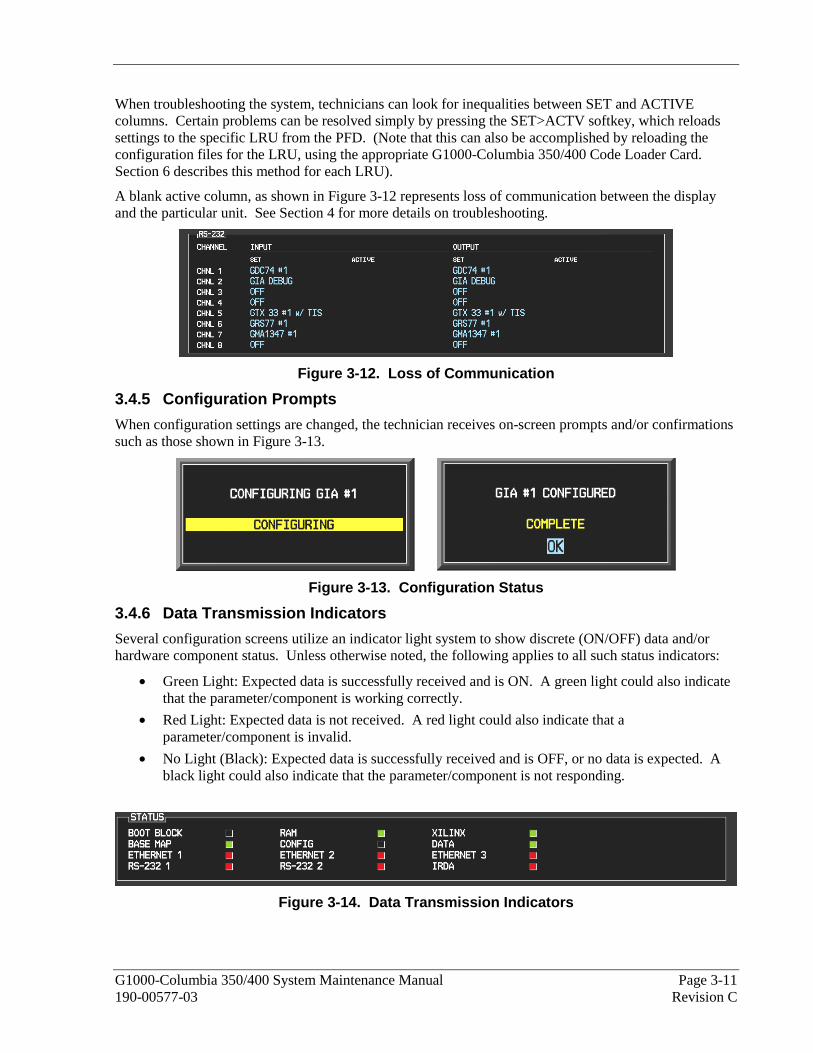
G1000-Columbia 350/400 System Maintenance Manual Page 3-11 190-00577-03 Revision C
When troubleshooting the system, technicians can look for inequalities between SET and ACTIVE columns. Certain problems can be resolved simply by pressing the SET>ACTV softkey, which reloads settings to the specific LRU from the PFD. (Note that this can also be accomplished by reloading the configuration files for the LRU, using the appropriate G1000-Columbia 350/400 Code Loader Card. Section 6 describes this method for each LRU).
A blank active column, as shown in Figure 3-12 represents loss of communication between the display and the particular unit. See Section 4 for more details on troubleshooting.
Figure 3-12. Loss of Communication
3.4.5 Configuration Prompts
When configuration settings are changed, the technician receives on-screen prompts and/or confirmations such as those shown in Figure 3-13.
Figure 3-13. Configuration Status
3.4.6 Data Transmission Indicators
Several configuration screens utilize an indicator light system to show discrete (ON/OFF) data and/or hardware component status. Unless otherwise noted, the following applies to all such status indicators:
• Green Light: Expected data is successfully received and is ON. A green light could also indicate that the parameter/component is working correctly.
• Red Light: Expected data is not received. A red light could also indicate that a parameter/component is invalid.
• No Light (Black): Expected data is successfully received and is OFF, or no data is expected. A black light could also indicate that the parameter/component is not responding.
Figure 3-14. Data Transmission Indicators

Page 3-12 G1000-Columbia 350/400 System Maintenance Manual Revision C 190-00577-03
3.5 Configuration Mode Navigation Using the FMS knob as described in Section 3.1.1 a user can navigate through different pages and page groups in the Configuration Mode. For complete description and breakdown of each page, refer to the G1000 Configuration manual, Garmin part number 190-00303-04.
The following diagram shows the layout and organization of Configuration Mode page groups and pages.
1. RS-232 / ARINC 429 Config Page2. GDU Status Page3. GDU Test Page4. Diagnostics Page5. Serial/Ethernet I/O Page
6. Alert Configuration Page7. Airframe Configuration Page
1. Engine Data Page2. GEA Status Page3. GEA Configuration Page
1. RS-232 / ARINC 429 Config Page2. Transponder Configuration Page
1. AHRS Air Data Input Page2. GRS / GMU Calibration Page
1. GDC Configuration Page
1. GMA Configuration Page
1. RS-232 / ARINC 429 Config Page2. CAN / RS-485 Config Page3. GIA I/O Configuration Page4. COM Setup Page5. GIA Status Page
1. System Status Page2. Date/Time Setup Page3. Main Lighting Page4. Audio Alert Configuration Page5. Software Upload Page
6. Configuration Upload Page7. File Manager Page8. Diagnostics Terminal Page9. Aircraft Diagnostics Page
10. System Configuration Page11. Manifest Configuration Page
1. GDL 69 Configuration Page
1. GFC Configuration Page2. GFC Status Page
1. Fuel Calibration Page2. Fuel Tank Calibration Page3. Flaps and Trim Calibration Page
1. Remote Controller Status
Figure 3-15. Configuration Page Navigator

G1000-Columbia 350/400 System Maintenance Manual 4-1 190-00577-03 Revision C
4 TROUBLESHOOTING This section provides instructions and guidance for G1000 system troubleshooting, as installed in the Columbia 350/400.
NOTE
Sections 5, 6 and 7 provide detailed instructions on equipment removal, replacement, configuration, and return-to-service testing, respectively. Anytime a G1000 component or LRU is removed, swapped, or replaced, the technician must follow the procedures given in Sections 5, 6 and 7 to ensure proper operation of the system.
Troubleshoot the G1000 system by first identifying, then isolating the specific failure to the responsible LRU. There are several indications that the G1000 presents to the pilot or technician, showing overall system condition. A course of action should be determined based on the information presented on the display. This section shows possible scenarios likely to be encountered during normal operation and gives troubleshooting guidance to the technician to resolve problems.
Figure 4-1. System Status Page (AUX Group Normal Mode)
The 6th AUX group page on the MFD provides LRU health status by means of a green check or a red ‘X’. Also, LRU software versions are shown along with other database versions and dates. If a red ‘X’ is shown for an LRU, see the appropriate LRU troubleshooting section of this chapter for guidance. Typically, the G1000 Alerting System provides alerts/annunciations in conjunction with the information presented at the 6th AUX page.
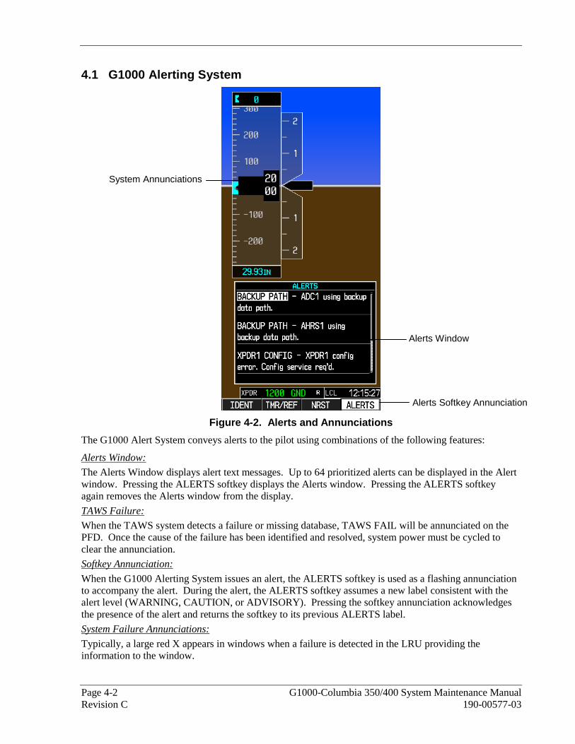
Page 4-2 G1000-Columbia 350/400 System Maintenance Manual Revision C 190-00577-03
4.1 G1000 Alerting System
Figure 4-2. Alerts and Annunciations
The G1000 Alert System conveys alerts to the pilot using combinations of the following features:
Alerts Window:
The Alerts Window displays alert text messages. Up to 64 prioritized alerts can be displayed in the Alert window. Pressing the ALERTS softkey displays the Alerts window. Pressing the ALERTS softkey again removes the Alerts window from the display.
TAWS Failure:
When the TAWS system detects a failure or missing database, TAWS FAIL will be annunciated on the PFD. Once the cause of the failure has been identified and resolved, system power must be cycled to clear the annunciation.
Softkey Annunciation:
When the G1000 Alerting System issues an alert, the ALERTS softkey is used as a flashing annunciation to accompany the alert. During the alert, the ALERTS softkey assumes a new label consistent with the alert level (WARNING, CAUTION, or ADVISORY). Pressing the softkey annunciation acknowledges the presence of the alert and returns the softkey to its previous ALERTS label.
System Failure Annunciations:
Typically, a large red X appears in windows when a failure is detected in the LRU providing the information to the window.
Alerts Window
System Annunciations
Alerts Softkey Annunciation

G1000-Columbia 350/400 System Maintenance Manual Page 4-3 190-00577-03 Revision C
The G1000 Alert System uses three levels:
WARNING Annunciation:
This level of alert requires immediate pilot attention. A warning alert is accompanied by an annunciation in the Annunciation Window. Warning alert text appearing in the Annunciation Window is RED. A warning alert is also accompanied by a flashing WARNING softkey annunciation, as shown in Figure 4-3, along with a continuous aural tone. Pressing the WARNING softkey acknowledges the presence of the alert and stops the aural tone. Pressing the ALERTS softkey displays the related alert message in the Alert Window.
Figure 4-3. WARNING Softkey Annunciation
CAUTION Annunciation:
This level of alert indicates the existence of abnormal conditions on the aircraft that may require pilot intervention. A caution alert is accompanied by an annunciation in the Annunciation Window. Caution alert text appearing in the Annunciation Window is yellow. A caution alert is also accompanied by a flashing CAUTION softkey annunciation, as shown in Figure 4-4, along with a single aural tone. Pressing the CAUTION softkey acknowledges the presence of the alert. Pressing the ALERTS softkey displays the related alert message in the Alert Window.
Figure 4-4. CAUTION Softkey Annunciation
ADVISORY Annunciation:
This level of alert provides general information to the pilot. An advisory annunciation issues both an annunciation and a text message. An advisory annunciation is also accompanied by a flashing ADVISORY softkey annunciation, as shown in Figure 4-5. Pressing the ADVISORY softkey acknowledges the presence of the alert and displays the advisory message in the Alert Window.
Figure 4-5. ADVISORY Softkey Annunciation
If an alert is acknowledged but still active, the ALERTS key will be displayed as black text on a white background. If there are currently no active alerts, the ALERTS key will be displayed as white text on a black background.

Page 4-4 G1000-Columbia 350/400 System Maintenance Manual Revision C 190-00577-03
4.2 System Annunciations If data fields become invalid due to an LRU failure, the PFD/MFD typically annunciates the failure with a large red X, as shown in the figure below.
Attitude: GRS 77 AHRSHeading: GRS 77 or GMU 44
#1 and #2 GIA 63 or GEA 71
or equivalentEngine/Airframe Sensors
#1 GIA 63
#2 GIA 63
#1 GIA 63
#2 GIA 63
GDC 74AAir Data Computer
GTX 33 Transponder or#1 and # 2 GIA 63
GPS Receivers in #1 or #2 GIA 63GTP 59 OAT Probeor GDC 74A ADC
Figure 4-6. System Annunciations
The GFC 700 AFCS Annunciation field is located above the airspeed tape on the PFD as shown:
Figure 4-7. AFCS Annunciation Field

G1000-Columbia 350/400 System Maintenance Manual Page 4-5 190-00577-03 Revision C
Figure 4-8. TAWS Annunciation Field
The following table provides basic troubleshooting guidance for LRU failures:
Invalid Data Field Associated LRU(s) Solution
NAV1 & COM1
GIA1
• Check configuration settings for GIA1 and the PFD. • Switch GIA1 and GIA2, to verify location of problem:
If problem follows the GIA, replace the GIA. If problem persists, check Ethernet interconnect
from GIA1 to the PFD, and then replace the PFD if wiring discrepancies are not found.
NAV2 & COM2
GIA2
• Check configuration settings for GIA2 and the MFD.
• Switch GIA1 and GIA2, to verify location of problem: If problem follows the GIA, replace the GIA. If problem persists, check Ethernet interconnect
from GIA2 to the MFD, and then replace the MFD if wiring discrepancies are not found.
GPS INTEG & Time
GIA1 and GIA2
• Ensure that a cell phone or a device using cell phone technology is not turned on (even in a monitoring state) in the cabin.
• Check GPS1 and GPS2 signal strength on AUX page 3. • Check corresponding GPS antenna and cable.
• Check Ethernet interconnect between the PFD and GIA1 or MFD and GIA2 for faults.
• Switch GIA1 and GIA2, to verify location of problem: If problem follows the GIA, replace the GIA. If problem persists, replace the MFD or PFD.

Page 4-6 G1000-Columbia 350/400 System Maintenance Manual Revision C 190-00577-03
Invalid Data Field Associated LRU(s) Solution
XPDR FAIL
GTX 33
• Check GTX 33 configuration settings for GIA1 and GIA2.
• Perform a SET>ACTV configuration reset on the GTX Config page, and verify the aircraft registration is present.
• Replace the GTX 33.
TAS FAIL AIRSPEED FAIL ALTITUDE FAIL
VERT SPEED FAIL
GDC 74A
• Verify that there are no GDC configuration or manifest errors in the ALERT window.
• Inspect GDC 74A pitot/static plumbing integrity.
• Inspect pitot/static ports and associated equipment for faults.
• For TAS failure, also check GTP 59 OAT probe as stated below.
• Check GDC 74 configuration settings for the PFD, MFD, GIA1, and GIA2.
If PFDs, MFD, and GIA configuration settings are correct, replace the GDC configuration module.
If problem persists, replace the GDC 74A.
OAT
and TAS
GTP 59
• Check OAT probe wiring and connectors for faults. • Check GDC configuration module wiring for damage,
replace if any is found. • Replace GDC configuration module.
• Replace GDC 74A with a known good unit: If problem persists, replace the GTP 59.

G1000-Columbia 350/400 System Maintenance Manual Page 4-7 190-00577-03 Revision C
Invalid Data Field Associated LRU(s) Solution
ATTITUDE FAIL
GRS 77
• Note: AHRS requires valid ADC and GPS position. • Ensure that a cell phone or a device using cell phone
technology is not turned on (even in a monitoring state) in the cabin.
• Cycle GRS 77 power to restart initialization. • Ensure GRS 77 connecter is secure and proper wire
harness strain relief is provided. • Ensure the GRS 77 is fastened down tightly in it’s
mounting rack and that the mounting rack is not loose (CAUTION - do not loosen the mounting rack hardware to the airframe shelf or the aircraft will need to be leveled and the PITCH/ROLL OFFSET procedure performed).
• Ensure GPS has acquired at least four satellites, has a 3D navigation solution, and a DOP of less than 5.0. This is particularly important for an ATTITUDE FAIL that appears during ground operation only.
• Perform an Engine Run-Up Test to check if engine vibration is causing the GRS 77 to go offline.
• Load configuration files to the PFD, MFD, GIA1, and GIA2.
• Calibrate the GRS 77 (Pitch/Roll Offset and Magnetometer Calibration).
• Replace GRS 77 . If problem persists replace GRS 77 configuration
module. See Section 3.4 for configuration instructions.
• Contact Garmin Aviation Product Support if condition continues after replacing the GRS 77 and configuration module for additional assistance.
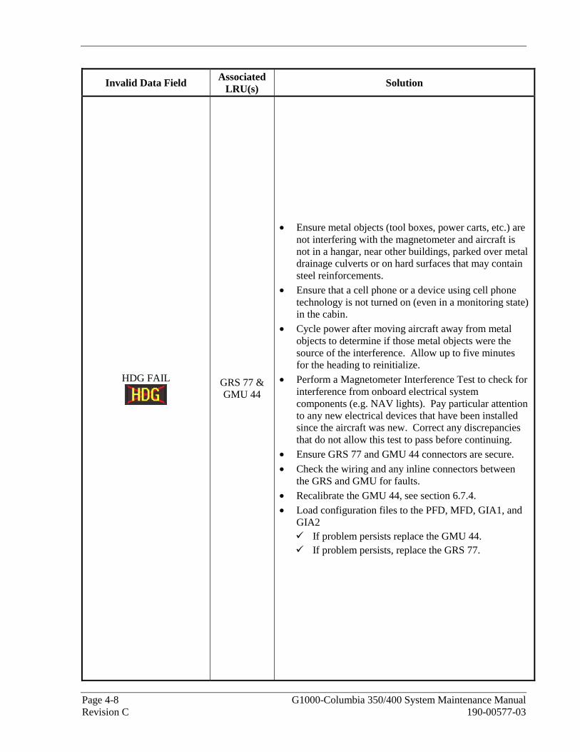
Page 4-8 G1000-Columbia 350/400 System Maintenance Manual Revision C 190-00577-03
Invalid Data Field Associated LRU(s) Solution
HDG FAIL
GRS 77 & GMU 44
• Ensure metal objects (tool boxes, power carts, etc.) are not interfering with the magnetometer and aircraft is not in a hangar, near other buildings, parked over metal drainage culverts or on hard surfaces that may contain steel reinforcements.
• Ensure that a cell phone or a device using cell phone technology is not turned on (even in a monitoring state) in the cabin.
• Cycle power after moving aircraft away from metal objects to determine if those metal objects were the source of the interference. Allow up to five minutes for the heading to reinitialize.
• Perform a Magnetometer Interference Test to check for interference from onboard electrical system components (e.g. NAV lights). Pay particular attention to any new electrical devices that have been installed since the aircraft was new. Correct any discrepancies that do not allow this test to pass before continuing.
• Ensure GRS 77 and GMU 44 connectors are secure.
• Check the wiring and any inline connectors between the GRS and GMU for faults.
• Recalibrate the GMU 44, see section 6.7.4. • Load configuration files to the PFD, MFD, GIA1, and
GIA2 If problem persists replace the GMU 44. If problem persists, replace the GRS 77.

G1000-Columbia 350/400 System Maintenance Manual Page 4-9 190-00577-03 Revision C
Invalid Data Field Associated LRU(s) Solution
Engine/Airframe Sensors (All Invalid)
GEA 71
• Check for GEA related Alert messages on the PFD. Correct any Alerts concerning software or configuration errors by reloading software or configuration as noted.
• Verify GEA internal power supply, configuration, and calibration status in configuration mode.
Configuration and calibration boxes should be green. If they are red, replace the GEA 71.
The INT PWR SUPPLY box should be green. If it is red, check for a shorted airframe sensor (reference Columbia wiring schematics for your aircraft type) by unplugging airframe sensors that receive power from the GEA one at a time until the INT PWR SUPPLY box turns green. The last sensor that was unplugged before the box turned green is the cause of the problem. Replace that sensor (reference Columbia Aircraft Maintenance Manual for instructions).
• Verify internal, external, and reference voltages listed in the Main Analog and I/O A Analog boxes are not dashed out (does not include Aircraft Power 1 and 2). Reference Section 2.7.1.2.
If any voltages are dashed out, replace the GEA. • Ensure the GEA is online (green checkmark on the
AUX – SYSTEM STATUS page). If GEA is not online verify unit is receiving power
at the rack connector. Check the GIA/GEA interconnects for faults. Reload configuration files to both GIA’s and the
GEA. If problem persists, replace the GEA 71.
• For only Red-X of the EGT, TIT and CHT temperature readings, replace the GEA configuration module and back shell thermocouple.
If problem persists, replace the GEA 71.

Page 4-10 G1000-Columbia 350/400 System Maintenance Manual Revision C 190-00577-03
The following table provides guidance for troubleshooting individual engine/airframe sensor failures. Be sure to also follow previous guidance given for the GEA 71.
The technician should troubleshoot to isolate the fault by checking sensor-to-GEA wiring, replacing the suspect sensor, and finally by replacing the GEA 71. Replace one part at a time. Refer to Section 6.4.4.1 to check for correct operation of the sensors and GEA 71 after any part has been replaced.
Invalid Field Sensor Solution
Tachometer
• Check tachometer – GEA wiring. Refer to latest revision of the 350/400 electrical manual.
• Replace tachometer sensor. Refer to 350/400 AMM.
• Replace GEA 71.
MAP Sensor
• Check MAP sensor – GEA wiring. Refer to latest revision of the 350/400 electrical manual.
• Replace MAP sensor.
• Replace GEA 71.
Fuel Flow
• Check fuel flow sensor – GEA wiring. Refer to the latest revision of the 350/400 electrical manual.
• Replace fuel flow sensor. Refer to 350/400 AMM.
• Replace GEA 71.
Oil Pressure Sensor
• Check oil pressure sensor – GEA wiring. Refer to latest revision of the 350/400 electrical manual.
• Replace oil pressure sensor. Refer to 350/400 AMM.
• Replace GEA 71.
Oil Temperature
Sensor
• Check oil temperature sensor – GEA wiring. Refer to latest revision of the 350/400 electrical manual.
• Replace oil temperature sensor. Refer to 350/400 AMM.
• Replace GEA 71.
Fuel Quantity Sensors (2 per side)
• Check fuel quantity sensor – GEA wiring. Refer to latest revision of the 350/400 electrical manual.
• Replace fuel quantity sensor. Refer to the 350/400 AMM.
• Replace GEA 71.

G1000-Columbia 350/400 System Maintenance Manual Page 4-11 190-00577-03 Revision C
Invalid Field Sensor Solution
CHT Probes (6)
• Check CHT probe – GEA wiring. Refer to the 350/400 AMM.
• Replace CHT probe. Refer to the 350/400 AMM. If all 6 CHT indicators are flagged, check the following:
• Replace backshell thermocouple and configuration module in GEA connector. See Section 2.1.4.
• Replace GEA 71.
EGT Probes (6)
• Check EGT probe – GEA wiring. Refer to the 350/400 AMM.
• Replace EGT probe. Refer to the 350/400 AMM. If all 6 EGT indicators are flagged, check the following:
• Replace backshell thermocouple and configuration module in GEA connector. See Section 2.1.4.
• Replace GEA 71.
TIT Probe (Columbia 400 only)
• Check TIT Probe – GEA wiring. • Replace temperature probe. Refer to the 350/400
AMM. If both TIT indicators are flagged, check the following:
• Replace backshell thermocouple and configuration module in GEA connector. See Section 2.1.4.
• Replace GEA 71.
Alternator Current Shunt
• Check current sensor – GEA wiring. Refer to latest revision of the 350/400 electrical manual.
• Replace current sensor. Refer to 350/400 AMM.
• Replace GEA 71.
Battery Current Shunt
• Check current sensor – GEA wiring. Refer to latest revision of the 350/400 electrical manual.
• Replace current sensor. Refer to 350/400 AMM.
• Replace GEA 71.
Bus Voltage
• Check bus voltage – GEA wiring • Replace GEA 71.

Page 4-12 G1000-Columbia 350/400 System Maintenance Manual Revision C 190-00577-03
Invalid Field Sensor Solution
Oxygen Quantity Pressure Sensor
• Check Oxygen Qty Pressure Sensor – GEA wiring.
• Replace Oxygen Qty Pressure Sensor. Refer to the 350/400 AMM.
If both Oxy Qty and Oxy Outlet Pressure indicators are flagged, check the following:
• Reload GEA configuration for the Oxygen Option. • Replace GEA 71.
Oxygen Outlet
Pressure Sensor
• Check Oxygen Outlet Pressure Sensor – GEA wiring. • Replace Oxygen Outlet Pressure Sensor. Refer to the
350/400 AMM. If both Oxy Qty and Oxy Outlet Pressure indicators are
flagged, check the following:
• Reload GEA configuration for the Oxygen Option.
• Replace GEA 71. 4.2.1 AFCS System Troubleshooting
The information in this section specifically relates to the GFC 700. Should a problem be encountered during the operation of the GFC 700, the pilot and technician should first evaluate the overall status and condition of the G1000 system on the AUX – System Status page (on the MFD). Any alert messages, annunciations, or other abnormal behaviors should be noted in an effort to pinpoint the fault. More detailed system troubleshooting for a red AFCS or red PFT annunciation is contained in this section.
Annunciations and Alerts
The GFC 700 AFCS Annunciation field is located above the airspeed tape on the PFD as shown in Figure 4-9.
Figure 4-9. AFCS Annunciation Field

G1000-Columbia 350/400 System Maintenance Manual Page 4-13 190-00577-03 Revision C
The following annunciations may appear in the AFCS Annunciation field:
Annunciation Condition Solutions
AFCS System
Failure
• Ensure that the G1000 system is in proper working order. Check specifically for proper operation of the:
GIA 63 Integrated Avionics Unit GRS 77 AHRS (it must align before this
annunciation will disappear and allow the PFT to start)
GDC 74A Air Data Computer All GSA 81 Servos GTA 82 Trim adapter (A/P Trim is on)
• Check that no red X’s are present on the MFD and PFDs. • Check that there are no Alert messages present in the
PFD Alert window. Correct any software or configuration errors noted.
• Go to the AUX SYSTEM STATUS page on the MFD and verify that all LRUs have a ‘green’ check.
• If the OAT and TAS is Red-X’d and the attitude indication is present, replace the GDC 74 configuration module.
Pitch Axis Failure
Pitch Trim Axis
Failure
Roll Axis Failure
• Check the AUX – SYSTEM STATUS page to see if the servo is online (green check).
• Check that the affected servo is receiving power.
• Check the servo wiring and connector.
• Ensure PTRM switches are not stuck. • If failure condition still exists, remove and replace the
affected servo.
Elevator Mistrim
Down
Elevator Mistrim
Up
• If mistrim annunciations persist, check the Pitch Trim servo for proper operation. Verify that the servo is online at the AUX – SYSTEM STATUS page.
• Check the Pitch Trim servo wiring and connector. Ensure the servo is receiving power.
• Check the aircraft trim control rigging. • If mistrim condition still exists, remove and replace the
affected servo.
Aileron Mistrim
Right
Aileron Mistrim
Left
• Check for possible fuel imbalance. • Check aileron control rigging.
• If mistrim condition still exists remove and replace the roll servo.
Pre-Flight Test • Reset servo power by cycling the circuit breaker.

Page 4-14 G1000-Columbia 350/400 System Maintenance Manual Revision C 190-00577-03
4.3 Columbia 350/400 Specific Alerts The following alerts are configured specifically for the Columbia 350/400:
WARNING Alerts:
Annunciation Window Alert Definition Solution
DOOR OPEN Door not secured.
• Ensure baggage door is secured.
• Verify the wiring between the baggage door switch and the GEA 71. Refer to latest revision of the 350/400 electrical manual.
• Troubleshoot according to the 350/400 AMM.
FUEL VALVE Fuel tank is not correctly selected or in OFF position.
• Ensure fuel selector valve is in the desired position.
• Verify wiring between left and/or right fuel selector switch and the GEA 71. Refer to latest revision of the 350/400 electrical manual.
• Troubleshoot according to the 350/400 AMM.
• Replace GEA 71.
L BUS OFF No power on the left bus.
• Ensure left left battery switch is on and left bus is powered.
• Verify wiring between GEA 71 and circuit breaker panel. Refer to latest revision of the 350/400 electrical manual.
• Replace GEA 71.
R BUS OFF No power on the right bus.
• Ensure right battery master switch is on and right bus is powered.
• Verify wiring between GEA 71 and circuit breaker panel. Refer to latest revision of the 350/400 electrical manual.
• Replace GEA 71.
CO LVL HIGH Carbon monoxide level is too high.
• Ensure CO level in cockpit is less than 75 ppm. • Press CO RST button.
• Replace CO Guardian.
OIL PRES LOW
Low oil pressure.
• Verify wiring between GEA 71 and oil pressure switch. Refer to latest revision of the 350/400 electrical manual.
• Troubleshoot according to the 350/400 AMM. • Replace oil pressure switch.
• Replace GEA 71.

G1000-Columbia 350/400 System Maintenance Manual Page 4-15 190-00577-03 Revision C
CAUTION Alerts: Annunciation
Window Alert Definition Solution
L LOW FUEL Less than 8 gallons in left
tank.
• Check the discrete wiring between low fuel sensor and the GEA 71. Refer to latest revision of the 350/400 electrical manual.
• Troubleshoot according to the 350/400 AMM.
• Replace GEA 71.
R LOW FUEL Less than 8 gallons in right
tank.
• Check the discrete wiring between low fuel sensor and the GEA 71. Refer to latest revision of the 350/400 electrical manual.
• Troubleshoot according to the 350/400 AMM. • Replace GEA 71.
FUEL PUMP Indicates when the backup
fuel pump is needed.
• Check the wiring between the fuel pump and the GEA 71. Refer to latest revision of the 350/400 electrical manual.
• Troubleshoot according to the 350/400 AMM.
• Replace GEA 71.
L ALT OUT Left alternator offline.
• With the engine running, ensure that the correct alternator switch is in the ON position.
• Check the bus voltage, if it is above 27 VDC, the alternator is probably supplying current to bus.
• Verify the wiring from the left voltage regulator to the GEA
• Troubleshoot according to the 350/400 AMM.
• Replace GEA 71.
R ALT OUT Right alternator offline.
• With the engine running, ensure that the correct alternator switch is in the ON position.
• Check the bus voltage, if it is above 27 VDC, the alternator is probably supplying current to bus.
• Verify the wiring from the left voltage regulator to the GEA
• Troubleshoot according to the 350/400 AMM.
• Replace GEA 71.
OXYGEN Oxygen system is OFF and
altitude is greater than 12000 feet.
• Turn oxygen system on when above 12,000 ft.
OXYGEN QTY Low oxygen quantity. • Ensure oxygen quantity is greater than 250 psi. • Troubleshoot oxygen system according to the
350/400 AMM.

Page 4-16 G1000-Columbia 350/400 System Maintenance Manual Revision C 190-00577-03
Annunciation Window Alert Definition Solution
OXYGEN PRES Low oxygen outlet pressure.
• Ensure manual valve is ON.
• Ensure oxygen outlet pressure is greater than 17.5 psi.
• Troubleshoot oxygen system according to the 350/400 AMM.
STARTER ENGD
Starter relay has power applied.
• This annunciation is normal during the time that the starter is engaged in cranking the engine for engine start.
• If the annunciation fails to illuminate during engine cranking, verify the wiring between the Starter Relay and the GEA 71. Refer to latest revision of the 350/400 electrical manual.
• A stuck starter will result in a very high electrical load on the alternator , which can be verified on the PFD.
• If the annunciation fails to extinguish after cranking is finished, turn off the engine immediately.
• Troubleshoot according to the 350/400 AMM.
• Replace GEA 71.
ADVISORY Annunciations:
Annunciation Window Alert Definition Solution
SPEED BRAKES Speed brakes are extended.
• Verify speed brake switch position. • Verify wiring between the ALC speed brake in
the avionics bay and the No. 1 or No. 2 GIA 63. Refer to latest revision of the 350/400 electrical manual.
• Troubleshoot according to the 350/400 AMM.
• Replace GIA 63.
RUDR LMTR Rudder limiter is engaged. (350 Only)
• Verify state of rudder limiter system. • Check rudder limiter wiring to the GEA 71.
• Replace GEA 71.
RUDR HOLD Rudder hold is engaged. (400 Only)
• Verify state of rudder hold system.
• Check rudder hold wiring to the GEA 71. • Replace GEA 71.
OXYGEN ON Reminder to turn oxygen off when on the ground.
• Ensure oxygen system is off.
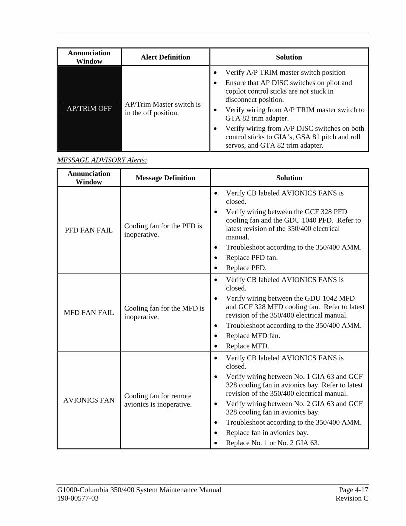
G1000-Columbia 350/400 System Maintenance Manual Page 4-17 190-00577-03 Revision C
Annunciation Window Alert Definition Solution
AP/TRIM OFF AP/Trim Master switch is in the off position.
• Verify A/P TRIM master switch position
• Ensure that AP DISC switches on pilot and copilot control sticks are not stuck in disconnect position.
• Verify wiring from A/P TRIM master switch to GTA 82 trim adapter.
• Verify wiring from A/P DISC switches on both control sticks to GIA’s, GSA 81 pitch and roll servos, and GTA 82 trim adapter.
MESSAGE ADVISORY Alerts:
Annunciation Window Message Definition Solution
PFD FAN FAIL Cooling fan for the PFD is inoperative.
• Verify CB labeled AVIONICS FANS is closed.
• Verify wiring between the GCF 328 PFD cooling fan and the GDU 1040 PFD. Refer to latest revision of the 350/400 electrical manual.
• Troubleshoot according to the 350/400 AMM.
• Replace PFD fan. • Replace PFD.
MFD FAN FAIL Cooling fan for the MFD is inoperative.
• Verify CB labeled AVIONICS FANS is closed.
• Verify wiring between the GDU 1042 MFD and GCF 328 MFD cooling fan. Refer to latest revision of the 350/400 electrical manual.
• Troubleshoot according to the 350/400 AMM. • Replace MFD fan.
• Replace MFD.
AVIONICS FAN Cooling fan for remote avionics is inoperative.
• Verify CB labeled AVIONICS FANS is closed.
• Verify wiring between No. 1 GIA 63 and GCF 328 cooling fan in avionics bay. Refer to latest revision of the 350/400 electrical manual.
• Verify wiring between No. 2 GIA 63 and GCF 328 cooling fan in avionics bay.
• Troubleshoot according to the 350/400 AMM.
• Replace fan in avionics bay. • Replace No. 1 or No. 2 GIA 63.

Page 4-18 G1000-Columbia 350/400 System Maintenance Manual Revision C 190-00577-03
Annunciation Window Message Definition Solution
FUEL IMBAL Fuel imbalance is greater than 10 gallons.
• Ensure L and R fuel quantities are within 10 gallons of each other.
• Ensure fuel senders are not sticking.
• Verify wiring between GEA 71 and left inboard sender. Refer to latest revision of the 350/400 electrical manual.
• Verify wiring between GEA 71 and left sender.
• Verify wiring between GEA 71 and right sender.
• Troubleshoot according to the 350/400 AMM.
• Replace fuel sender.
• Replace GEA 71.
LOW MAN PRESS
Manifold pressure is below 15 in.
• Verify wiring between GEA 71 and MAP sensor in engine compartment. Refer to latest revision of the 350/400 electrical manual.
• Replace MAP sensor
• Replace GEA 71.
VAPOR SUPPR Turn on Vapor Suppression (400 Only)
• Verify wiring between No. 1 and No. 2 GIA 63 and vapor suppression switch. Refer to latest revision of the 350/400 electrical manual.
• Replace vapor suppression switch.
• Replace GIA 63.
TIMER ZERO Timer has counted down to zero. • Reset timer if desired.

G1000-Columbia 350/400 System Maintenance Manual Page 4-19 190-00577-03 Revision C
4.4 GDU 1040/1042 Troubleshooting
NOTE
Garmin recommends the use of SanDisk or Toshiba SD cards to load G1000 software and configuration files. If another brand of card is used, and software loading problems occur, replace the card with a SanDisk or Toshiba card and reattempt the software load.
4.4.1 GDU 1040/1042 Common Problems
Symptom Recommended Action Display will not track photocell
Keypad/bezel will not track photocell
• Reload PFD and MFD configuration files. • Ensure that the panel dimming potentiometer is set to minimum
level. • Go to the GDU TEST page in configuration mode. Cover and
uncover the photocells and verify that PHOTOCELL A or PHOTOCELL B value changes.
If values do not change, replace the display. Display will not track dimmer bus
Keypad/bezel will not track dimmer bus
• Reload PFD and MFD configuration files. • Check display lighting settings on the Main Lighting page and
ensure dimmer input tracks dimmer setting. • Switch MFD and PFD.
If problem follows unit, replace display per Section 5.1. If condition remains in original position after swapping
displays, check the GDU dimmer input to verify voltage is present.
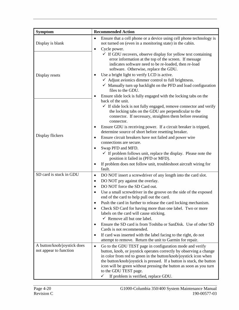
Page 4-20 G1000-Columbia 350/400 System Maintenance Manual Revision C 190-00577-03
Symptom Recommended Action
Display is blank
Display resets
Display flickers
• Ensure that a cell phone or a device using cell phone technology is not turned on (even in a monitoring state) in the cabin.
• Cycle power. If GDU recovers, observe display for yellow text containing
error information at the top of the screen. If message indicates software need to be re-loaded, then re-load software. Otherwise, replace the GDU.
• Use a bright light to verify LCD is active. Adjust avionics dimmer control to full brightness. Manually turn up backlight on the PFD and load configuration
files to the GDU. • Ensure slide lock is fully engaged with the locking tabs on the
back of the unit. If slide lock is not fully engaged, remove connector and verify
the locking tabs on the GDU are perpendicular to the connector. If necessary, straighten them before reseating connector.
• Ensure GDU is receiving power. If a circuit breaker is tripped, determine source of short before resetting breaker.
• Ensure circuit breakers have not failed and power wire connections are secure.
• Swap PFD and MFD. If problem follows unit, replace the display. Please note the
position it failed in (PFD or MFD). • If problem does not follow unit, troubleshoot aircraft wiring for
fault. SD card is stuck in GDU • DO NOT insert a screwdriver of any length into the card slot.
• DO NOT pry against the overlay. • DO NOT force the SD Card out. • Use a small screwdriver in the groove on the side of the exposed
end of the card to help pull out the card. • Push the card in further to release the card locking mechanism. • Check SD Card for having more than one label. Two or more
labels on the card will cause sticking. Remove all but one label.
• Ensure the SD card is from Toshiba or SanDisk. Use of other SD Cards is not recommended.
• If card was inserted with the label facing to the right, do not attempt to remove. Return the unit to Garmin for repair.
A button/knob/joystick does not appear to function
• Go to the GDU TEST page in configuration mode and verify button, knob, or joystick operates correctly by observing a change in color from red to green in the button/knob/joystick icon when the button/knob/joystick is pressed. If a button is stuck, the button icon will be green without pressing the button as soon as you turn to the GDU TEST page.
If problem is verified, replace GDU.
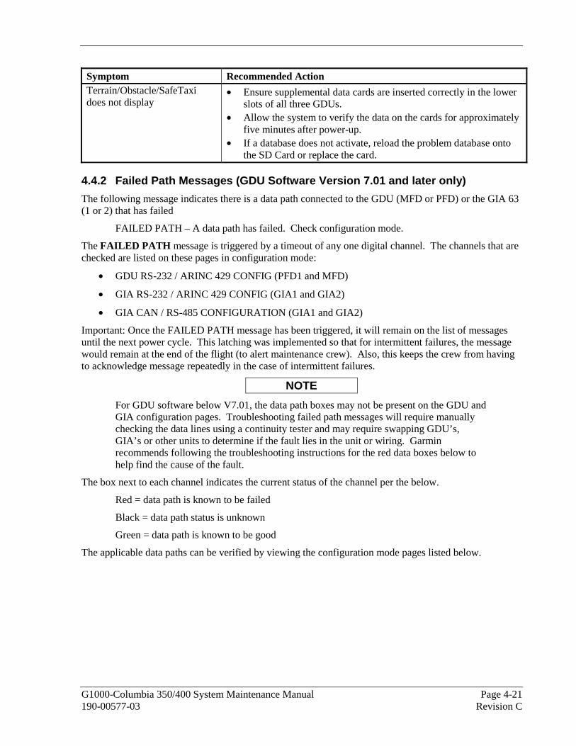
G1000-Columbia 350/400 System Maintenance Manual Page 4-21 190-00577-03 Revision C
Symptom Recommended Action Terrain/Obstacle/SafeTaxi does not display
• Ensure supplemental data cards are inserted correctly in the lower slots of all three GDUs.
• Allow the system to verify the data on the cards for approximately five minutes after power-up.
• If a database does not activate, reload the problem database onto the SD Card or replace the card.
4.4.2 Failed Path Messages (GDU Software Version 7.01 and later only)
The following message indicates there is a data path connected to the GDU (MFD or PFD) or the GIA 63 (1 or 2) that has failed
FAILED PATH – A data path has failed. Check configuration mode.
The FAILED PATH message is triggered by a timeout of any one digital channel. The channels that are checked are listed on these pages in configuration mode:
• GDU RS-232 / ARINC 429 CONFIG (PFD1 and MFD)
• GIA RS-232 / ARINC 429 CONFIG (GIA1 and GIA2)
• GIA CAN / RS-485 CONFIGURATION (GIA1 and GIA2)
Important: Once the FAILED PATH message has been triggered, it will remain on the list of messages until the next power cycle. This latching was implemented so that for intermittent failures, the message would remain at the end of the flight (to alert maintenance crew). Also, this keeps the crew from having to acknowledge message repeatedly in the case of intermittent failures.
NOTE
For GDU software below V7.01, the data path boxes may not be present on the GDU and GIA configuration pages. Troubleshooting failed path messages will require manually checking the data lines using a continuity tester and may require swapping GDU’s, GIA’s or other units to determine if the fault lies in the unit or wiring. Garmin recommends following the troubleshooting instructions for the red data boxes below to help find the cause of the fault.
The box next to each channel indicates the current status of the channel per the below.
Red = data path is known to be failed
Black = data path status is unknown
Green = data path is known to be good
The applicable data paths can be verified by viewing the configuration mode pages listed below.
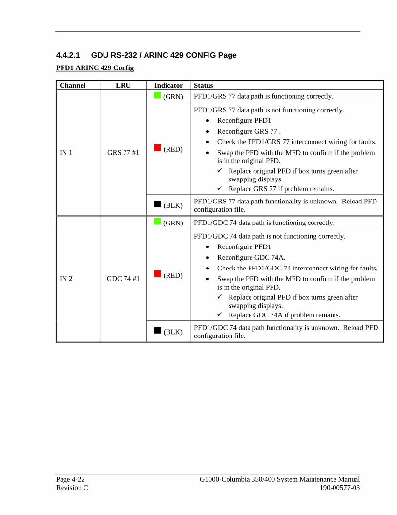
Page 4-22 G1000-Columbia 350/400 System Maintenance Manual Revision C 190-00577-03
4.4.2.1 GDU RS-232 / ARINC 429 CONFIG Page
PFD1 ARINC 429 Config Channel LRU Indicator Status
(GRN) PFD1/GRS 77 data path is functioning correctly.
(RED)
PFD1/GRS 77 data path is not functioning correctly.
• Reconfigure PFD1.
• Reconfigure GRS 77 .
• Check the PFD1/GRS 77 interconnect wiring for faults.
• Swap the PFD with the MFD to confirm if the problem is in the original PFD.
Replace original PFD if box turns green after swapping displays.
Replace GRS 77 if problem remains.
IN 1 GRS 77 #1
(BLK) PFD1/GRS 77 data path functionality is unknown. Reload PFD configuration file.
(GRN) PFD1/GDC 74 data path is functioning correctly.
(RED)
PFD1/GDC 74 data path is not functioning correctly.
• Reconfigure PFD1.
• Reconfigure GDC 74A.
• Check the PFD1/GDC 74 interconnect wiring for faults.
• Swap the PFD with the MFD to confirm if the problem is in the original PFD.
Replace original PFD if box turns green after swapping displays.
Replace GDC 74A if problem remains.
IN 2 GDC 74 #1
(BLK) PFD1/GDC 74 data path functionality is unknown. Reload PFD configuration file.

G1000-Columbia 350/400 System Maintenance Manual Page 4-23 190-00577-03 Revision C
MFD1 ARINC 429 Config Channel LRU Indicator Status
(GRN) MFD1/GRS 77 data path is functioning correctly.
(RED)
MFD1/GRS 77 data path is not functioning correctly.
• Reconfigure MFD1.
• Reconfigure GRS 77 .
• Check the MFD1/GRS 77 interconnect wiring for faults.
• Swap the MFD with the PFD to confirm if the problem is in the original MFD.
Replace original MFD if box turns green after swapping displays.
Replace GRS 77 if problem remains.
IN 1 GRS 77 #1
(BLK) MFD1/GRS 77 data path functionality is unknown. Reload MFD configuration file.
(GRN) MFD1/GDC 74 data path is functioning correctly.
(RED)
MFD1/GDC 74 data path is not functioning correctly.
• Reconfigure MFD1.
• Reconfigure GDC 74A.
• Check the MFD1/GDC 74 interconnect wiring for faults.
• Swap the MFD with the PFD to confirm if the problem is in the original MFD.
Replace original MFD if box turns green after swapping displays.
Replace GDC 74A if problem remains.
IN 2 GDC 74 #1
(BLK) MFD1/GDC 74 data path functionality is unknown. Reload MFD configuration file.
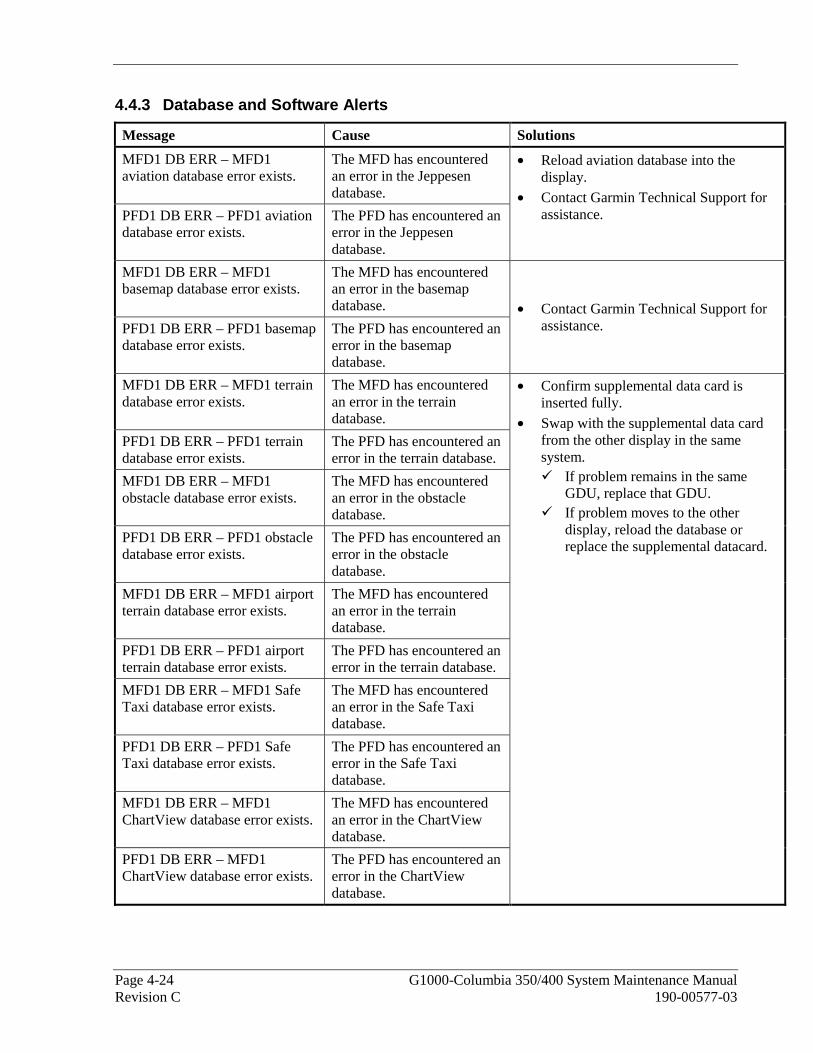
Page 4-24 G1000-Columbia 350/400 System Maintenance Manual Revision C 190-00577-03
4.4.3 Database and Software Alerts
Message Cause Solutions
MFD1 DB ERR – MFD1 aviation database error exists.
The MFD has encountered an error in the Jeppesen database.
PFD1 DB ERR – PFD1 aviation database error exists.
The PFD has encountered an error in the Jeppesen database.
• Reload aviation database into the display.
• Contact Garmin Technical Support for assistance.
MFD1 DB ERR – MFD1 basemap database error exists.
The MFD has encountered an error in the basemap database.
PFD1 DB ERR – PFD1 basemap database error exists.
The PFD has encountered an error in the basemap database.
• Contact Garmin Technical Support for assistance.
MFD1 DB ERR – MFD1 terrain database error exists.
The MFD has encountered an error in the terrain database.
PFD1 DB ERR – PFD1 terrain database error exists.
The PFD has encountered an error in the terrain database.
MFD1 DB ERR – MFD1 obstacle database error exists.
The MFD has encountered an error in the obstacle database.
PFD1 DB ERR – PFD1 obstacle database error exists.
The PFD has encountered an error in the obstacle database.
MFD1 DB ERR – MFD1 airport terrain database error exists.
The MFD has encountered an error in the terrain database.
PFD1 DB ERR – PFD1 airport terrain database error exists.
The PFD has encountered an error in the terrain database.
MFD1 DB ERR – MFD1 Safe Taxi database error exists.
The MFD has encountered an error in the Safe Taxi database.
PFD1 DB ERR – PFD1 Safe Taxi database error exists.
The PFD has encountered an error in the Safe Taxi database.
MFD1 DB ERR – MFD1 ChartView database error exists.
The MFD has encountered an error in the ChartView database.
PFD1 DB ERR – MFD1 ChartView database error exists.
The PFD has encountered an error in the ChartView database.
• Confirm supplemental data card is inserted fully.
• Swap with the supplemental data card from the other display in the same system.
If problem remains in the same GDU, replace that GDU.
If problem moves to the other display, reload the database or replace the supplemental datacard.

G1000-Columbia 350/400 System Maintenance Manual Page 4-25 190-00577-03 Revision C
Message Cause Solutions
DB MISMATCH – Aviation database version mismatch. Xtalk is off.
The G1000 has found the Jeppesen aviation database in the PFD and MFD do not match.
• Load current Jeppesen database to both displays.
DB MISMATCH – Aviation database type mismatch. Xtalk is off.
The G1000 has found the Jeppesen aviation database types do not match.
• Load same type Jeppesen database to both displays.
DB MISMATCH – Basemap database version mismatch. Xtalk is off.
The PFD and MFD have different basemap versions installed.
• Contact Garmin Technical Support for assistance.
DB MISMATCH – Terrain database version mismatch. Xtalk is off.
The PFD and MFD have different terrain database versions installed.
DB MISMATCH – Obstacle database version mismatch. Xtalk is off.
The PFD and MFD have different obstacle database versions installed.
DB MISMATCH – Terrain database type mismatch. Xtalk is off.
The PFD and MFD have different terrain database types installed.
• Insert two identical version Terrain database cards in the PFD and MFD.
SW MISMATCH – GDU software version mismatch. Xtalk is off.
The G1000 has found the PFD and MFD software versions do not match.
• Load correct software version into both PFD and MFD.
MANIFEST – PFD1 software mismatch. Communication Halted.
The system has detected an incorrect software version loaded in the PFD.
MANIFEST – MFD software mismatch. Communication Halted.
The system has detected an incorrect software version loaded in MFD.
• Load correct software version.

Page 4-26 G1000-Columbia 350/400 System Maintenance Manual Revision C 190-00577-03
Message Cause Solutions
CNFG MODULE – PFD1 configuration module is inoperative.
The PFD master configuration module has failed.
• Check master configuration module connector and wiring for damage inside the GDU connector backshell.
Replace master configuration module wiring and pins.
If problem persists, replace master configuration module.
NOTE New Terrain/Obstacle cards, Jeppesen Aviation Database and other optional features (i.e. TAWS unlock card) will need to be replaced if the master configuration module is changed. The G1000 System ID number will change to a new number when installing a new master configuration module. The old Terrain and other cards will no longer work as they will remain locked to the old System ID number.
Display will not track photocell
• Ensure that the panel dimming potentiometer is set to minimum level. • Check display lighting settings on the Main Lighting page and ensure
lighting is configured correctly. • If problem persists, replace defective display per Section 5.1.
Keypad/bezel will not track photocell
• Ensure that the panel dimming potentiometer is set to minimum level. • Check keyboard lighting settings on the Main Lighting page and ensure
lighting is configured correctly. • If problem persists, replace defective display per Section 5.1.
Display will not track dimmer bus
• Check display lighting settings on the Main Lighting page and ensure dimmer input tracks dimmer setting.
• Check wiring. • Switch MFD and PFD. If problem follows unit, replace defective
display per Section 5.1.
Keypad/bezel will not track dimmer bus
• Check keyboard lighting settings on the Main Lighting page and ensure dimmer input tracks dimmer setting.
• Check wiring. • Switch MFD and PFD. If problem follows unit, replace defective
display per Section 5.1.

G1000-Columbia 350/400 System Maintenance Manual Page 4-27 190-00577-03 Revision C
4.4.4 GDU Cooling Alerts
Message Cause Solutions
MFD1 COOLING – has poor cooling. Reducing power usage.
MFD1 has exceeded its operating temperature range.
• Check cooling fan and wiring for proper operation (if applicable).
Replace cooling fan if unable to determine if operating correctly.
If problem persists, replace the MFD.
• If problem continues contact Garmin Aviation Product Support for assistance.
PFD1 COOLING – has poor cooling. Reducing power usage.
The PFD has exceeded its operating temperature range.
• Check cooling fan and wiring for proper operation (if applicable).
Replace cooling fan if unable to determine if operating correctly.
If problem persists, replace the PFD.
• If problem continues contact Garmin Aviation Product Support for assistance.
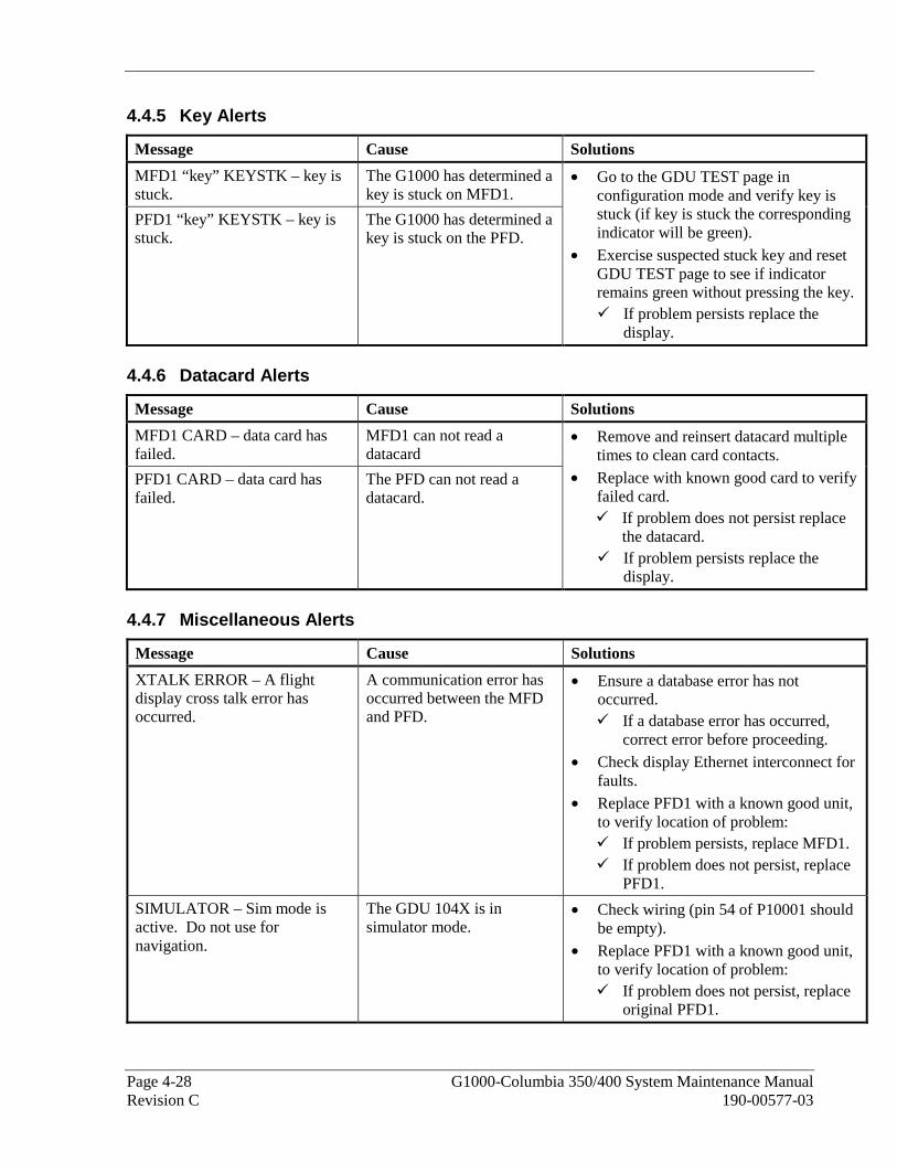
Page 4-28 G1000-Columbia 350/400 System Maintenance Manual Revision C 190-00577-03
4.4.5 Key Alerts
Message Cause Solutions
MFD1 “key” KEYSTK – key is stuck.
The G1000 has determined a key is stuck on MFD1.
PFD1 “key” KEYSTK – key is stuck.
The G1000 has determined a key is stuck on the PFD.
• Go to the GDU TEST page in configuration mode and verify key is stuck (if key is stuck the corresponding indicator will be green).
• Exercise suspected stuck key and reset GDU TEST page to see if indicator remains green without pressing the key.
If problem persists replace the display.
4.4.6 Datacard Alerts
Message Cause Solutions
MFD1 CARD – data card has failed.
MFD1 can not read a datacard
PFD1 CARD – data card has failed.
The PFD can not read a datacard.
• Remove and reinsert datacard multiple times to clean card contacts.
• Replace with known good card to verify failed card.
If problem does not persist replace the datacard.
If problem persists replace the display.
4.4.7 Miscellaneous Alerts
Message Cause Solutions
XTALK ERROR – A flight display cross talk error has occurred.
A communication error has occurred between the MFD and PFD.
• Ensure a database error has not occurred.
If a database error has occurred, correct error before proceeding.
• Check display Ethernet interconnect for faults.
• Replace PFD1 with a known good unit, to verify location of problem:
If problem persists, replace MFD1. If problem does not persist, replace
PFD1.
SIMULATOR – Sim mode is active. Do not use for navigation.
The GDU 104X is in simulator mode.
• Check wiring (pin 54 of P10001 should be empty).
• Replace PFD1 with a known good unit, to verify location of problem:
If problem does not persist, replace original PFD1.
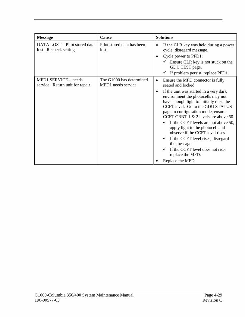
G1000-Columbia 350/400 System Maintenance Manual Page 4-29 190-00577-03 Revision C
Message Cause Solutions
DATA LOST – Pilot stored data lost. Recheck settings.
Pilot stored data has been lost.
• If the CLR key was held during a power cycle, disregard message.
• Cycle power to PFD1: Ensure CLR key is not stuck on the
GDU TEST page. If problem persist, replace PFD1.
MFD1 SERVICE – needs service. Return unit for repair.
The G1000 has determined MFD1 needs service.
• Ensure the MFD connector is fully seated and locked.
• If the unit was started in a very dark environment the photocells may not have enough light to initially raise the CCFT level. Go to the GDU STATUS page in configuration mode, ensure CCFT CRNT 1 & 2 levels are above 50.
If the CCFT levels are not above 50, apply light to the photocell and observe if the CCFT level rises.
If the CCFT level rises, disregard the message.
If the CCFT level does not rise, replace the MFD.
• Replace the MFD.

Page 4-30 G1000-Columbia 350/400 System Maintenance Manual Revision C 190-00577-03
Message Cause Solutions
PFD1 SERVICE – needs service. Return unit for repair.
The G1000 has determined the PFD needs service.
• Ensure the PFD connector is fully seated and locked.
• If the unit was started in a very dark environment the photocells may not have enough light to initially raise the CCFT level. Go to the GDU STATUS page in configuration mode, ensure CCFT CRNT 1 & 2 levels are above 50.
If the CCFT levels are not above 50, apply light to the photocell and observe if the CCFT level rises.
If the CCFT level rises, disregard the message.
If the CCFT level does not rise, replace the PFD.
• Replace the PFD.
NOTE New Terrain/Obstacle cards, Jeppesen Aviation Database and other optional features (i.e. TAWS unlock card) will need to be replaced if the master configuration module is changed. The G1000 System ID number will change to a new number when installing a new master configuration module. The old Terrain and other cards will no longer work as they will remain locked to the old System ID number.

G1000-Columbia 350/400 System Maintenance Manual Page 4-31 190-00577-03 Revision C
Message Cause Solutions
PFD1 CONFIG – PFD1 configuration error. Config service req’d.
The G1000 has detected a PFD configuration mismatch.
• Reload PFD1 configuration files from SD Loader Card.
• Reload system configuration files by pressing the UPDT CFG softkey on the Configuration Upload Page in the System Page Group to load configuration files into the configuration module. If message persists, check
configuration module wiring for faults and replace if necessary.
If issue continues, replace master configuration module.
If problem persists, replace the PFD.
NOTE New Terrain/Obstacle cards, Jeppesen Aviation Database and other optional features (i.e. TAWS unlock card) will need to be replaced if the master configuration module is changed. The G1000 System ID number will change to a new number when installing a new master configuration module. The old Terrain and other cards will no longer work as they will remain locked to the old System ID number.
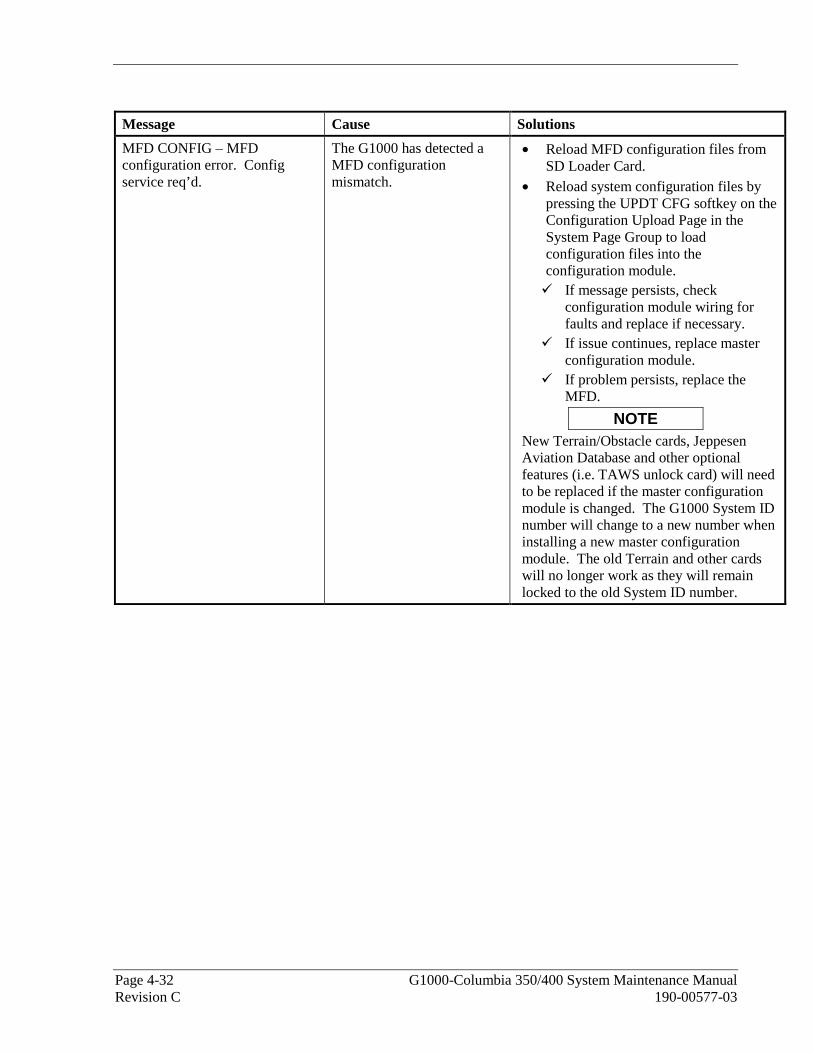
Page 4-32 G1000-Columbia 350/400 System Maintenance Manual Revision C 190-00577-03
Message Cause Solutions
MFD CONFIG – MFD configuration error. Config service req’d.
The G1000 has detected a MFD configuration mismatch.
• Reload MFD configuration files from SD Loader Card.
• Reload system configuration files by pressing the UPDT CFG softkey on the Configuration Upload Page in the System Page Group to load configuration files into the configuration module. If message persists, check
configuration module wiring for faults and replace if necessary.
If issue continues, replace master configuration module.
If problem persists, replace the MFD.
NOTE New Terrain/Obstacle cards, Jeppesen Aviation Database and other optional features (i.e. TAWS unlock card) will need to be replaced if the master configuration module is changed. The G1000 System ID number will change to a new number when installing a new master configuration module. The old Terrain and other cards will no longer work as they will remain locked to the old System ID number.

G1000-Columbia 350/400 System Maintenance Manual Page 4-33 190-00577-03 Revision C
Message Cause Solutions TAWS FAIL A TAWS system failure has
occurred. • If message occurred on the first power
up after unlocking TAWS, cycle power to initialize TAWS.
• Ensure each GDU contains a TAWS/TERRAIN data card.
• Ensure all GDUs are TAWS configured. If all GDUs are not TAWS
configured, reconfigure. • Verify GIA #1 is online. • Ensure an Airport Terrain, Obstacle,
Terrain, Aviation Database, or GDU SW mismatch has not occurred. If a mismatch has occurred, load
correct database/software files or replace the terrain card.
TAWS TEST TAWS system is currently being tested.
• Normal annunciation during self test. Test will take up to two minutes to complete.
TAWS INHB TAWS system alerting is disabled
• Enable TAWS system alerting by pressing the MENU button from the MAP – TAWS page.
TAWS N/A GPS system integrity not high enough to enable TAWS
• Ensure valid GPS position is received from the AUX – GPS STATUS page.
HIGH VOLTS Main (M) or Essential (E) Bus voltage has exceeded 32 volts.
• Troubleshoot a possible alternator high voltage condition using Columbia Maintenance Manual.
CO LVL HIGH Unsafe carbon monoxide level reported by CO Guardian unit.
• Refer to Columbia Pilot’s Operating Handbook (POH).
PFD1 VOLTAGE – PFD1 has low voltage. Reducing power usage.
The PFD supply voltage is low.
• Check input voltage to PFD. • If input voltage is ok, replace PFD.
MFD1 VOLTAGE – MDF1 has low voltage. Reducing power usage.
The MFD supply voltage is low.
• Check input voltage to MFD. • If input voltage is ok, replace MFD.
CO DET SRVC – The carbon monoxide detector needs service.
The G1000 has determined the CO Guardian needs service.
• Replace the CO Guardian.
CO DET FAIL – The carbon monoxide detector is inoperative.
The G1000 and CO Guardian are not communicating.
• Check GIA/CO Guardian interconnect. • Replace the CO Guardian.
• Contact Garmin Product Support for Assistance.

Page 4-34 G1000-Columbia 350/400 System Maintenance Manual Revision C 190-00577-03
4.5 GMA 1347
4.5.1.1 GMA CONFIGURATION Page
Figure 4-10. GMA CONFIGURATION Page
NOTE
The GMA configuration settings are approved under the Columbia TC. Changes to these values could adversely affect pilot/crew alerting. For example: Decreasing an unswitched input volume level could cause certain alerts not to be heard.
SELECT GMA UNIT
This window shows the currently selected GMA 1347 audio panel.
HEADSET VOLUME
Adjustable range is between –31 and 31 for the following:
MUSIC #1, 2: Sets the music input volume levels.
UNSWITCHED IN #1, 2, 3: Sets unswitched input volume levels.
ALTITUDE WARNING: Sets the altitude warning input volume level. SPEAKER VOLUME
CREW AUDIO: Sets the crew audio volume level. Speaker volume adjustable range is between –31 and 31. MASTER SQUELCH
THRESHOLD VALUE: Sets the Master Avionics Squelch (MASQ™) threshold value. Value is adjustable between –31 and 31. MARKER BEACON
HI/LO SENSE THRESHOLD: Sets Hi/Lo marker sensitivity thresholds, value is adjustable between –31 and 31.
G1000-Columbia 350/400 System Maintenance Manual Page 4-35 190-00577-03 Revision C
VOLUME: Adjusts marker beacon volume, value is adjustable between –31 and 31. KEYPAD ANNUNCIATORS
The following audio panel settings can be enabled or disabled:
DISABLE COM3: Disables COM3 button in situations where no COM3 is installed.
DISABLE TEL: Disables TEL button in situations where no telephone is installed.
DISABLE DME: Disables DME button for situations where no DME is installed.
DISABLE ADF: Disables ADF button for situations where no ADF is installed.
DISABLE AUX: Disables AUX button for situations where no auxiliary input is connected.
DISABLE SPEAKER: Disables SPEAKER button for situations where no speaker output is connected.
DISABLE PA: Disables PA button for situations where no PA output is connected.
DISABLE PLAY: Disables PLAY button for situations where no play input is connected. CONFIGURATION INPUTS
The following audio panel settings can be enabled or disabled:
MASQ INHIBIT: Disable the Master Squelch circuit, which switches out aircraft radios during times of 'silence' to reduce the noise heard by the occupants. The Master Squelch threshold value is used to adjust the trip level of the circuit.
ICS MUTE: Mutes the MUSIC 1 channel during ICS activity.
INTERNAL SIDETONE: Causes the audio panel to provide COM sidetone in situations when the GIA radios do not provide sidetone.
MUTE AUDIO ON TX/RX: All secondary COM audio is muted upon transmitting over primary COM. Upon detection of primary COM transmission, all secondary COM is muted.
ANALOG INSTALL: COM 1 and COM 2 are connected using the analog interfaces instead of the digital interface.
RECORD COM 2: During split-COM operation, the digital clearance recorder records COM 2 only and playback only on the co-pilot’s channel.
POWER-UP w/ AUX ON: Enables the GMA 1347 to always power up with the AUX channel enabled.
DUAL INSTALL: The audio panel is part of a dual-installation.
DISABLE SPLIT COM: Allows split-COM feature to be disabled for installations where split-COM operation is not desired.
COM 2 ON-SIDE: In a dual audio panel installation, this designates the unit as a ‘right-hand/co-pilot’ unit.

Page 4-36 G1000-Columbia 350/400 System Maintenance Manual Revision C 190-00577-03
4.5.2 Common Problems
Symptom Recommended Action
Noise in Audio Most often the cause of the noise is external to the GMA. Try the following to locate the source of the noise: • Try a different pair of headsets. Noise cancelling headsets may pick up
and/or generate more noise than standard headsets from their own circuitry.
• Check for noise with engine turned off. If the noise is present only when the engine is running, check the
alternator and/or ignition system as possible sources of noise (see applicable airframe specific maintenance manual).
• Check for noise as all electrical equipment is turned on and off (strobes, other radios, etc.).
If the noise is identified from one electrical system or component refer to the applicable airframe specific maintenance manual.
• Ensure the NAV/COM squelch is not open. • Ensure the ADF and DME audio is not active.
• Ensure the marker beacon audio is not active.
• Ensure the ICS squelch is not open. Master squelch level can be adjusted on the GMA
CONFIGURATION page for higher noise environments. • Remove unit and check for MOD 1 marking.
If MOD 1 is not marked, replace GMA. • Replace unit only after all possible external sources of noise are
eliminated.
Some Buttons do not work. • Some buttons are disabled in the GMA CONFIGURATION page by default. This is to remove potential sources of audio noise for inputs that are not used. If in doubt as to which buttons should be disabled, reload GMA configuration file and other configuration files for optional equipment installed in the aircraft (i.e. ADF, DME) from the loader card.
COM Bleed over • Verify on the GMA CONFIGURATION page that “Disable Split COM” has a green box. Due to the closeness of the COM antennas and high power of the COM transceivers, Split COM operation is not approved. If the box is black (indicating COM 1/2 button is active), highlight “Disable Split COM” with the curser and press the ENT key to turn the box green which will deactivate Split COM mode.
Speaker Cuts Out • Reduce volume level of the item that caused the speaker to cut out when turned up. A speaker protection circuit disables the speaker output if the volume is too high. If the volume is not sufficient, replace aircraft cabin speaker, reference the Airframe Maintenance Manual.
Mic Audio Heard in Speaker • Reduce ICS Volume.
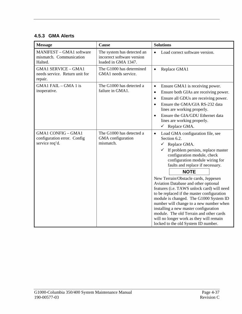
G1000-Columbia 350/400 System Maintenance Manual Page 4-37 190-00577-03 Revision C
4.5.3 GMA Alerts
Message Cause Solutions
MANIFEST – GMA1 software mismatch. Communication Halted.
The system has detected an incorrect software version loaded in GMA 1347.
• Load correct software version.
GMA1 SERVICE – GMA1 needs service. Return unit for repair.
The G1000 has determined GMA1 needs service.
• Replace GMA1
GMA1 FAIL – GMA 1 is inoperative.
The G1000 has detected a failure in GMA1.
• Ensure GMA1 is receiving power. • Ensure both GIAs are receiving power.
• Ensure all GDUs are receiving power. • Ensure the GMA/GIA RS-232 data
lines are working properly.
• Ensure the GIA/GDU Ethernet data lines are working properly.
Replace GMA.
GMA1 CONFIG – GMA1 configuration error. Config service req’d.
The G1000 has detected a GMA configuration mismatch.
• Load GMA configuration file, see Section 6.2.
Replace GMA. If problem persists, replace master
configuration module, check configuration module wiring for faults and replace if necessary.
NOTE New Terrain/Obstacle cards, Jeppesen Aviation Database and other optional features (i.e. TAWS unlock card) will need to be replaced if the master configuration module is changed. The G1000 System ID number will change to a new number when installing a new master configuration module. The old Terrain and other cards will no longer work as they will remain locked to the old System ID number.

Page 4-38 G1000-Columbia 350/400 System Maintenance Manual Revision C 190-00577-03
4.5.4 Backup Path Alerts
Message Cause Solutions
BACKUP PATH – Audio panel using backup data path.
The GMA 1347 is using a backup RS-232 data path.
Ensure the GMA/GIA RS-232 data lines are working properly.
ETHERNET ETHERNET
ETHERNET ETHERNET
RS
-232
RS
-232
GMA 1347 GMA 1347No. 1
GDU 1040PFD
No. 2GDU 104X
MFD
No.1GIA 63
No. 2GDU 104X
MFD
No. 1GDU 1040
PFD
Secondary Data PathPrimary Data Path
No. 2GIA 63
Figure 4-11. Backup Path Alerts

G1000-Columbia 350/400 System Maintenance Manual Page 4-39 190-00577-03 Revision C
4.6 GIA 63
4.6.1 Configuration Pages
4.6.1.1 RS-232/ARINC 429 Page
Figure 4-12. RS-232/ARINC 429
Main ARINC 429 and RS-232 communications channels for GIA 1 and GIA 2 are shown at this page. All settings are pre-established for a particular installation and are loaded from the G1000 Loader Card and should not be changed. The ‘GIA 1’ and ‘GIA 2’ configuration files contain the settings shown on this page.
SELECT UNIT
This window shows the currently selected GIA 63 unit. RS-232
This window shows active RS-232 configuration settings for currently selected GIA. ARINC 429
This window shows active ARINC 429 configuration settings for currently selected GIA. SOFTKEYS
The following softkeys appear at this page:
• SET>ACTV: See Section 3.4.4 for description.
• ACTV>SET: See Section 3.4.4 for description.
• CLR NV: Clears all ‘Active’ settings from memory from the selected GIA 63 and restores default settings. You will need to reload GIA and optional equipment configuration files if you clear the memory.

Page 4-40 G1000-Columbia 350/400 System Maintenance Manual Revision C 190-00577-03
4.6.1.2 CAN/RS-485 CONFIGURATION Page
Figure 4-13. CAN/RS-485 CONFIGURATION Page
This page shows settings for the Controller Area Network (CAN) and RS-485 channels used by the GIA 63 . All settings are pre-established for a particular installation and are loaded from the appropriate G1000 Loader Card and should not be changed. The ‘GIA 1’ and ‘GIA 2’ configuration files contain the settings shown on this page.
SELECT GIA UNIT
This window shows the currently selected GIA 63 . CAN
This window shows active Controller Area Network configuration settings for currently selected GIA. RS-485
This window shows active RS-485 configuration settings for currently selected GIA. CLOCKED DATA INTERFACE
This window shows active Clocked Data Interface settings, typically only used when interfacing to an external DME. SOFTKEYS
The following softkeys appear at this page:
• SET>ACTV: See Section 3.4.4 for description.
• ACTV>SET: See Section 3.4.4 for description.
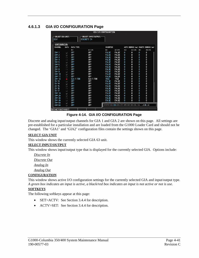
G1000-Columbia 350/400 System Maintenance Manual Page 4-41 190-00577-03 Revision C
4.6.1.3 GIA I/O CONFIGURATION Page
Figure 4-14. GIA I/O CONFIGURATION Page
Discrete and analog input/output channels for GIA 1 and GIA 2 are shown on this page. All settings are pre-established for a particular installation and are loaded from the G1000 Loader Card and should not be changed. The ‘GIA1’ and ‘GIA2’ configuration files contain the settings shown on this page.
SELECT GIA UNIT
This window shows the currently selected GIA 63 unit. SELECT INPUT/OUTPUT
This window shows input/output type that is displayed for the currently selected GIA. Options include:
Discrete In
Discrete Out
Analog In
Analog Out CONFIGURATION
This window shows active I/O configuration settings for the currently selected GIA and input/output type. A green box indicates an input is active, a black/red box indicates an input is not active or not is use. SOFTKEYS
The following softkeys appear at this page:
• SET>ACTV: See Section 3.4.4 for description.
• ACTV>SET: See Section 3.4.4 for description.
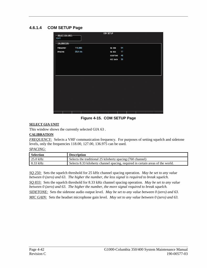
Page 4-42 G1000-Columbia 350/400 System Maintenance Manual Revision C 190-00577-03
4.6.1.4 COM SETUP Page
Figure 4-15. COM SETUP Page
SELECT GIA UNIT
This window shows the currently selected GIA 63 . CALIBRATION
FREQUENCY: Selects a VHF communication frequency. For purposes of setting squelch and sidetone levels, only the frequencies 118.00, 127.00, 136.975 can be used.
SPACING:
Selection Description 25.0 kHz Selects the traditional 25 kilohertz spacing (760 channel) 8.33 kHz Selects 8.33 kilohertz channel spacing, required in certain areas of the world.
SQ 250: Sets the squelch threshold for 25 kHz channel spacing operation. May be set to any value between 0 (zero) and 63. The higher the number, the less signal is required to break squelch.
SQ 833: Sets the squelch threshold for 8.33 kHz channel spacing operation. May be set to any value between 0 (zero) and 63. The higher the number, the more signal required to break squelch.
SIDETONE: Sets the sidetone audio output level. May be set to any value between 0 (zero) and 63.
MIC GAIN: Sets the headset microphone gain level. May set to any value between 0 (zero) and 63.
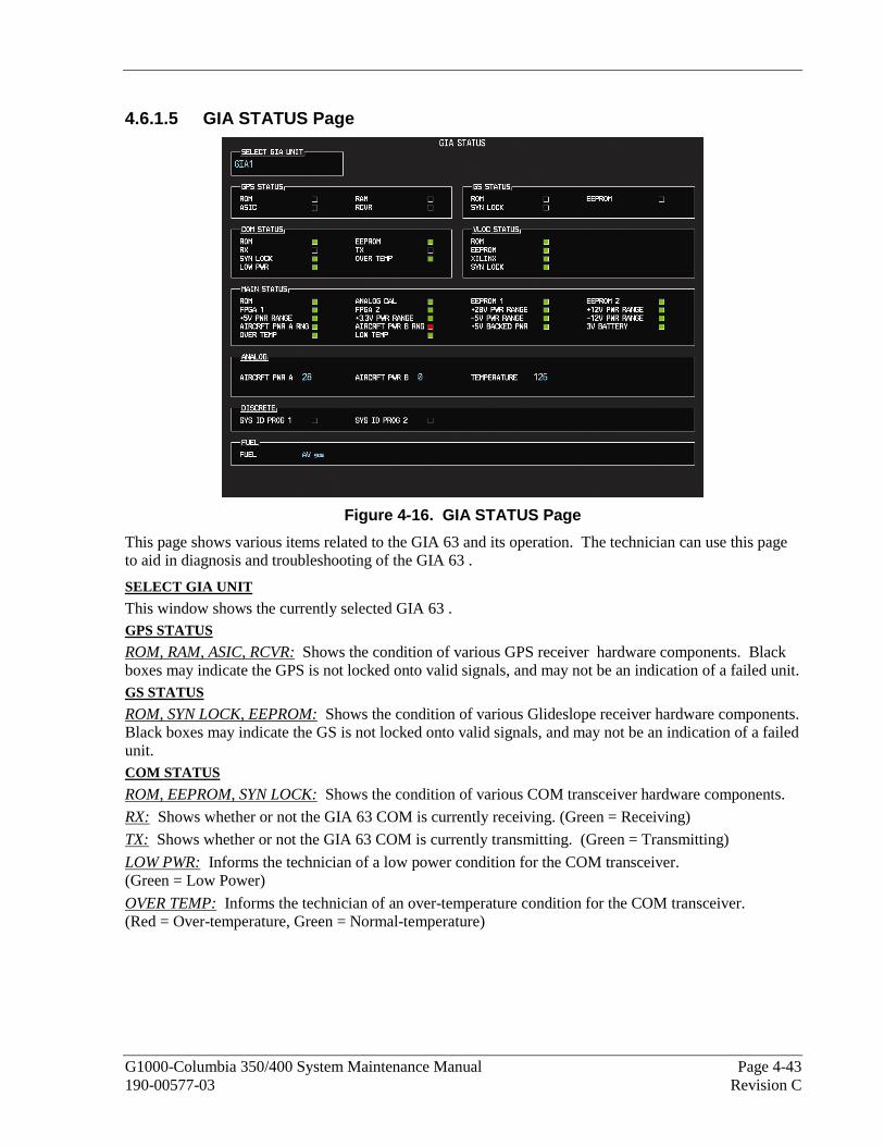
G1000-Columbia 350/400 System Maintenance Manual Page 4-43 190-00577-03 Revision C
4.6.1.5 GIA STATUS Page
Figure 4-16. GIA STATUS Page
This page shows various items related to the GIA 63 and its operation. The technician can use this page to aid in diagnosis and troubleshooting of the GIA 63 .
SELECT GIA UNIT
This window shows the currently selected GIA 63 . GPS STATUS
ROM, RAM, ASIC, RCVR: Shows the condition of various GPS receiver hardware components. Black boxes may indicate the GPS is not locked onto valid signals, and may not be an indication of a failed unit. GS STATUS
ROM, SYN LOCK, EEPROM: Shows the condition of various Glideslope receiver hardware components. Black boxes may indicate the GS is not locked onto valid signals, and may not be an indication of a failed unit. COM STATUS
ROM, EEPROM, SYN LOCK: Shows the condition of various COM transceiver hardware components.
RX: Shows whether or not the GIA 63 COM is currently receiving. (Green = Receiving)
TX: Shows whether or not the GIA 63 COM is currently transmitting. (Green = Transmitting)
LOW PWR: Informs the technician of a low power condition for the COM transceiver. (Green = Low Power)
OVER TEMP: Informs the technician of an over-temperature condition for the COM transceiver. (Red = Over-temperature, Green = Normal-temperature)

Page 4-44 G1000-Columbia 350/400 System Maintenance Manual Revision C 190-00577-03
VLOC STATUS
ROM, XILINX, SYN LOCK, EEPROM: Shows condition of various NAV receiver components. These boxes should be green, a red box indicates an internal failure. MAIN STATUS
ROM, FPGA 1/3, EEPROM 1/2: Shows the condition of various GIA 63 main board components. These boxes should be green, a red box indicates an internal failure.
+5, +3.3, -5, +12/-12, +28 PWR RANGE: Shows condition of various internal power supply ranges. They need to be within 10% of desired voltages. Replace the unit if these values are more than 10% from the desired voltage.
AIRCRFT PWR A/B RNG: Shows the technician that the main power inputs of the GIA 63 are within acceptable ranges. If a box is red, and the Aircraft PWR voltage is listed as 0 in the Analog Status box below, check that all aircraft buses are on and GIA breakers are pushed in.
ANALOG CAL: Shows the condition of the GIA calibration. (Green = Valid Analog Calibration)
OVER TEMP: Informs the technician of an over-temperature condition on the GIA 63 main board. (Red = Over-temperature, Green = Normal-temperature)
LOW TEMP: Informs the technician of a low temperature condition on the main board. (Red = Low-temperature, Green = Normal-temperature) ANALOG STATUS
AIRCRFT PWR A, B: Shows aircraft power input values, expressed in Volts DC. (Example: 2214 = 22.14 VDC)
TEMPERATURE: Shows the internal temperature of GIA unit, expressed in degrees Fahrenheit. (Example: 12267 = 122.67°F) DISCRETE
SYS ID PROG 1, 2: Identifies the assigned GIA number when two or more GIA units are installed. Green indicates that the System ID pin is left strapped to ground. Black indicates that the System ID pin is left ‘open’ and not strapped to ground.
GIA System ID 1 GIA System ID 2 GIA Unit Number
Black Black #1 GIA
Green Black #2 GIA
Black Green #3 GIA
Green Green #4 GIA
FUEL
FUEL: This window shows the type of fuel to be used on the aircraft.

G1000-Columbia 350/400 System Maintenance Manual Page 4-45 190-00577-03 Revision C
4.6.2 COM
Symptom Recommended Action
Weak COM transmit power • Switch GIA1 and GIA2, to verify location of problem: If problem follows unit, replace GIA. If problem does not follow unit, check COM antenna and cabling
for faults.
Weak COM receiver • Switch GIA1 and GIA2, to verify location of problem: If problem follows unit, replace GIA. If problem does not follow unit, check COM antenna and cabling
for faults.
No COM sidetone • Switch GIA1 and GIA2, to verify location of problem: If problem follows unit, replace GIA. If problem persists replace GMA 1347.
COM Bleedover • Verify on the GMA CONFIGURATION page that “Disable Split COM” has a green box. Due to the closeness of the COM antennas and high power of the COM transceivers, Split COM operation is not approved. If the box is black (indicating COM ½ button is active), highlight “Disable Split COM” with the curser and press the ENT key to turn the box green which will deactivate Split COM mode.

Page 4-46 G1000-Columbia 350/400 System Maintenance Manual Revision C 190-00577-03
4.6.3 GPS
Symptom Recommended Action
Will not acquire satellites • Ensure that a cell phone or a device using cell phone technology is not turned on (even in a monitoring state) in the cabin.
• Using the MFD AUX – GPS Status page, verify the signal strength bars are not erratic. If so, this indicates outside interference is affecting the GPS receivers. Find and remove the source of interference (i.e. cell phones, FBO datalink antennas, etc.).
• Check date and time on Date/Time Setup Page. If date and time are incorrect, enter the correct date and time.
• Switch GIA1 and GIA2, to verify location of problem: If problem follows unit, clear the GPS almanac by performing the
following steps – − Using the PFD in configuration mode, go to the GIA RS-
232/ARNIC 429 Config Page. − At the top of the screen, select the GIA that can not aquire
satellites (GIA1 or GIA2) and press the ENT key. − Press the “CLR NV” softkey at the bottom of the screen. − Select “OK” in the “Clear GIA nonvolatile memory?” pop-up
window.
− Next reload GIA Audio and Config files from a loader card, see Section 4.3 and on for instructions. Be sure to reload the configuration files for any optional equipment installed on the aircraft that require the GIA configuration to be updated.
• Cycle power on the system and allow it to restart in normal mode. Place the aircraft outside and allow 15-30 minutes for the GPS to acquire a position and download a new almanac.
If clearing nonvolatile memory is unsuccessful and the GPS still can not acquire a position, replace the GIA.
• If problem does not follow unit, check GPS antenna and cabling. 4.6.4 NAV
Symptom Recommended Action
Weak NAV receiver • Set up a NAV/COM Ramp Test Set to radiate a test signal. • Switch GIA1 and GIA2, to verify location of problem:
If problem follows unit, replace GIA. If problem does not follow unit, check NAV antenna, coupler, and
cabling for faults.

G1000-Columbia 350/400 System Maintenance Manual Page 4-47 190-00577-03 Revision C
4.6.5 G/S
Symptom Recommended Action
Weak G/S receiver • Set up a NAV/COM Ramp Test Set to radiate a test signal.
• Switch GIA1 and GIA2, to verify location of problem: If problem follows unit, replace GIA. If problem does not follow unit, check NAV antenna, coupler, and
cabling for faults.
4.6.6 COM Related Alerts
Message Cause Solutions
COM1 SERVICE – COM1 needs service. Return unit for repair.
The G1000 has determined COM1 needs service.
• Replace GIA1
COM2 SERVICE – COM2 needs service. Return unit for repair.
The G1000 has determined COM2 needs service.
• Replace GIA2
COM1 PTT – COM1 push-to-talk key is stuck.
The COM1 external push-to-talk (PTT) switch is stuck in the enabled (or “pressed”) state.
• Press the push-to-talk switch(s) again to cycle its operation.
• Check push-to-talk switch(s) and wiring.
• Check GIA1/GMA 1347 interconnect.
• Switch GIA1 and GIA2, to verify location of problem:
If problem follows the unit, replace GIA1.
If problem persists replace GMA 1347.
COM2 PTT – COM2 push-to-talk key is stuck.
The COM2 external push-to-talk (PTT) switch is stuck in the enabled (or “pressed”) state.
• Press the push-to-talk switch(s) again to cycle its operation.
• Check push-to-talk switch(s) and wiring.
• Check GIA2/GMA 1347 interconnect. • Switch GIA1 and GIA2, to verify
location of problem: If problem follows the unit, replace
GIA2. If problem persists replace GMA
1347.
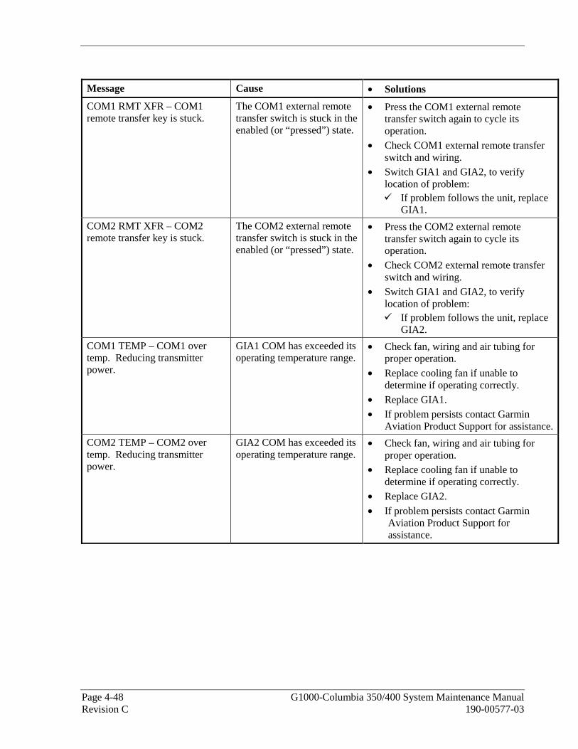
Page 4-48 G1000-Columbia 350/400 System Maintenance Manual Revision C 190-00577-03
Message Cause • Solutions
COM1 RMT XFR – COM1 remote transfer key is stuck.
The COM1 external remote transfer switch is stuck in the enabled (or “pressed”) state.
• Press the COM1 external remote transfer switch again to cycle its operation.
• Check COM1 external remote transfer switch and wiring.
• Switch GIA1 and GIA2, to verify location of problem:
If problem follows the unit, replace GIA1.
COM2 RMT XFR – COM2 remote transfer key is stuck.
The COM2 external remote transfer switch is stuck in the enabled (or “pressed”) state.
• Press the COM2 external remote transfer switch again to cycle its operation.
• Check COM2 external remote transfer switch and wiring.
• Switch GIA1 and GIA2, to verify location of problem:
If problem follows the unit, replace GIA2.
COM1 TEMP – COM1 over temp. Reducing transmitter power.
GIA1 COM has exceeded its operating temperature range.
• Check fan, wiring and air tubing for proper operation.
• Replace cooling fan if unable to determine if operating correctly.
• Replace GIA1. • If problem persists contact Garmin
Aviation Product Support for assistance.
COM2 TEMP – COM2 over temp. Reducing transmitter power.
GIA2 COM has exceeded its operating temperature range.
• Check fan, wiring and air tubing for proper operation.
• Replace cooling fan if unable to determine if operating correctly.
• Replace GIA2.
• If problem persists contact Garmin Aviation Product Support for assistance.

G1000-Columbia 350/400 System Maintenance Manual Page 4-49 190-00577-03 Revision C
4.6.7 NAV Related Alerts
Message Cause Solutions
NAV1 SERVICE – NAV1 needs service. Return unit for repair.
The G1000 has detected a failure in NAV1 receiver.
• Replace GIA1
NAV2 SERVICE – NAV2 needs service. Return unit for repair.
The G1000 has detected a failure in NAV2 receiver.
• Replace GIA2
NAV1 RMT XFR – NAV1 remote transfer key is stuck.
The NAV1 external remote transfer switch is stuck in the enabled (or “pressed”) state.
• Press the NAV1 external remote transfer switch again to cycle its operation.
• Check NAV1 remote transfer switch and wiring .
• Switch GIA1 and GIA2, to verify location of problem:
If problem follows the unit, replace GIA1.
NAV2 RMT XFR – NAV2 remote transfer key is stuck.
The NAV2 external remote transfer switch is stuck in the enabled (or “pressed”) state.
• Press the NAV2 external remote transfer switch again to cycle its operation.
• Check NAV2 remote transfer switch and wiring.
• Switch GIA1 and GIA2, to verify location of problem:
If problem follows the unit, replace GIA2.

Page 4-50 G1000-Columbia 350/400 System Maintenance Manual Revision C 190-00577-03
4.6.8 G/S Related Alerts
Message Cause Solutions
G/S1 SERVICE – G/S1 needs service. Return unit for repair.
The G1000 has detected a failure in G/S1 receiver.
• Replace GIA1
G/S2 SERVICE – G/S2 needs service. Return unit for repair.
The G1000 has detected a failure in G/S1 receiver.
• Replace GIA2
G/S1 FAIL – G/S1 is inoperative.
The G1000 has detected a failure in G/S1 receiver.
• Switch GIA1 and GIA2 to verify location of problem:
If problem follows the unit, replace GIA.
If problem does not follow unit, check G/S1 antenna and cabling.
G/S2 FAIL – G/S2 is inoperative.
The G1000 has detected a failure in G/S2 receiver.
• Switch GIA1 and GIA2 to verify location of problem:
If problem follows the unit, replace GIA.
If problem does not follow unit,. check G/S2 antenna and cabling.
4.6.9 GPS Related Alerts
NOTE
Before troubelshooting, ensure that no cellp hones or devices using cell phone technology are turned on, even in a monitoring state, in the cabin.
Message Cause Solutions
GPS1 SERVICE – GPS1 needs service. Return unit for repair.
The G1000 has detected a failure in GPS1 receiver.
• Replace GIA1
GPS2 SERVICE – GPS2 needs service. Return unit for repair.
The G1000 has detected a failure in GPS2 receiver.
• Replace GIA2
GPS1 FAIL – GPS1 is inoperative.
The G1000 has detected a failure in GPS1 receiver.
• Switch GIA1 and GIA2, to verify location of problem:
If problem follows the unit, replace GIA1.
If problem does not follow the unit, check GPS1 antenna and cabling.
GPS2 FAIL – GPS2 is inoperative.
The G1000 has detected a failure in GPS2 receiver.
• Switch GIA1 and GIA2, to verify location of problem:
If problem follows the unit, replace GIA2.
If problem does not follow the unit, check GPS2 antenna and cabling.
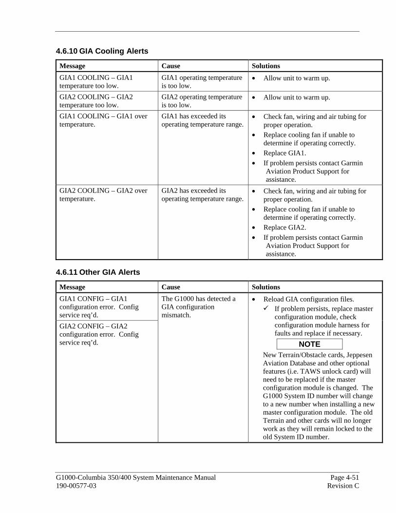
G1000-Columbia 350/400 System Maintenance Manual Page 4-51 190-00577-03 Revision C
4.6.10 GIA Cooling Alerts
Message Cause Solutions
GIA1 COOLING – GIA1 temperature too low.
GIA1 operating temperature is too low.
• Allow unit to warm up.
GIA2 COOLING – GIA2 temperature too low.
GIA2 operating temperature is too low.
• Allow unit to warm up.
GIA1 COOLING – GIA1 over temperature.
GIA1 has exceeded its operating temperature range.
• Check fan, wiring and air tubing for proper operation.
• Replace cooling fan if unable to determine if operating correctly.
• Replace GIA1.
• If problem persists contact Garmin Aviation Product Support for assistance.
GIA2 COOLING – GIA2 over temperature.
GIA2 has exceeded its operating temperature range.
• Check fan, wiring and air tubing for proper operation.
• Replace cooling fan if unable to determine if operating correctly.
• Replace GIA2.
• If problem persists contact Garmin Aviation Product Support for assistance.
4.6.11 Other GIA Alerts
Message Cause Solutions
GIA1 CONFIG – GIA1 configuration error. Config service req’d.
GIA2 CONFIG – GIA2 configuration error. Config service req’d.
The G1000 has detected a GIA configuration mismatch.
• Reload GIA configuration files. If problem persists, replace master
configuration module, check configuration module harness for faults and replace if necessary.
NOTE New Terrain/Obstacle cards, Jeppesen Aviation Database and other optional features (i.e. TAWS unlock card) will need to be replaced if the master configuration module is changed. The G1000 System ID number will change to a new number when installing a new master configuration module. The old Terrain and other cards will no longer work as they will remain locked to the old System ID number.
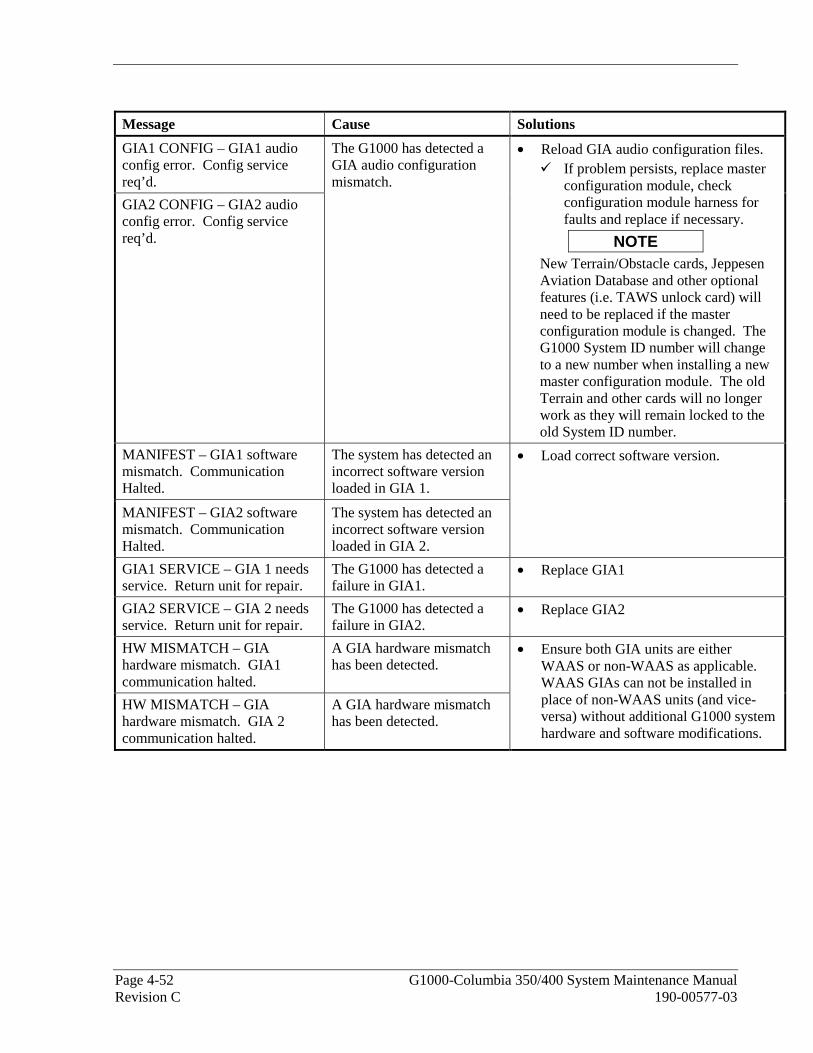
Page 4-52 G1000-Columbia 350/400 System Maintenance Manual Revision C 190-00577-03
Message Cause Solutions
GIA1 CONFIG – GIA1 audio config error. Config service req’d.
GIA2 CONFIG – GIA2 audio config error. Config service req’d.
The G1000 has detected a GIA audio configuration mismatch.
• Reload GIA audio configuration files. If problem persists, replace master
configuration module, check configuration module harness for faults and replace if necessary.
NOTE New Terrain/Obstacle cards, Jeppesen Aviation Database and other optional features (i.e. TAWS unlock card) will need to be replaced if the master configuration module is changed. The G1000 System ID number will change to a new number when installing a new master configuration module. The old Terrain and other cards will no longer work as they will remain locked to the old System ID number.
MANIFEST – GIA1 software mismatch. Communication Halted.
The system has detected an incorrect software version loaded in GIA 1.
MANIFEST – GIA2 software mismatch. Communication Halted.
The system has detected an incorrect software version loaded in GIA 2.
• Load correct software version.
GIA1 SERVICE – GIA 1 needs service. Return unit for repair.
The G1000 has detected a failure in GIA1.
• Replace GIA1
GIA2 SERVICE – GIA 2 needs service. Return unit for repair.
The G1000 has detected a failure in GIA2.
• Replace GIA2
HW MISMATCH – GIA hardware mismatch. GIA1 communication halted.
A GIA hardware mismatch has been detected.
HW MISMATCH – GIA hardware mismatch. GIA 2 communication halted.
A GIA hardware mismatch has been detected.
• Ensure both GIA units are either WAAS or non-WAAS as applicable. WAAS GIAs can not be installed in place of non-WAAS units (and vice-versa) without additional G1000 system hardware and software modifications.
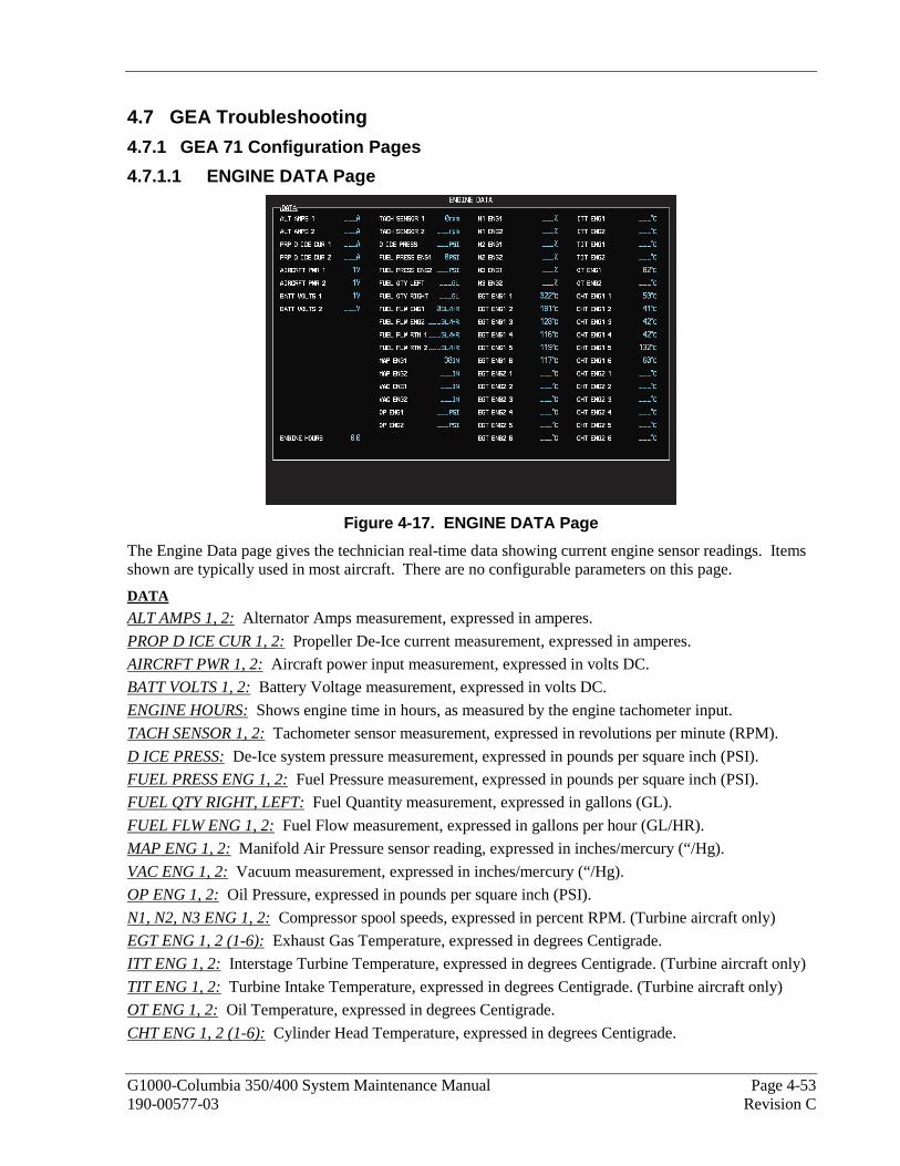
G1000-Columbia 350/400 System Maintenance Manual Page 4-53 190-00577-03 Revision C
4.7 GEA Troubleshooting
4.7.1 GEA 71 Configuration Pages
4.7.1.1 ENGINE DATA Page
Figure 4-17. ENGINE DATA Page
The Engine Data page gives the technician real-time data showing current engine sensor readings. Items shown are typically used in most aircraft. There are no configurable parameters on this page.
DATA
ALT AMPS 1, 2: Alternator Amps measurement, expressed in amperes.
PROP D ICE CUR 1, 2: Propeller De-Ice current measurement, expressed in amperes.
AIRCRFT PWR 1, 2: Aircraft power input measurement, expressed in volts DC.
BATT VOLTS 1, 2: Battery Voltage measurement, expressed in volts DC.
ENGINE HOURS: Shows engine time in hours, as measured by the engine tachometer input.
TACH SENSOR 1, 2: Tachometer sensor measurement, expressed in revolutions per minute (RPM).
D ICE PRESS: De-Ice system pressure measurement, expressed in pounds per square inch (PSI).
FUEL PRESS ENG 1, 2: Fuel Pressure measurement, expressed in pounds per square inch (PSI).
FUEL QTY RIGHT, LEFT: Fuel Quantity measurement, expressed in gallons (GL).
FUEL FLW ENG 1, 2: Fuel Flow measurement, expressed in gallons per hour (GL/HR).
MAP ENG 1, 2: Manifold Air Pressure sensor reading, expressed in inches/mercury (“/Hg).
VAC ENG 1, 2: Vacuum measurement, expressed in inches/mercury (“/Hg).
OP ENG 1, 2: Oil Pressure, expressed in pounds per square inch (PSI).
N1, N2, N3 ENG 1, 2: Compressor spool speeds, expressed in percent RPM. (Turbine aircraft only)
EGT ENG 1, 2 (1-6): Exhaust Gas Temperature, expressed in degrees Centigrade.
ITT ENG 1, 2: Interstage Turbine Temperature, expressed in degrees Centigrade. (Turbine aircraft only)
TIT ENG 1, 2: Turbine Intake Temperature, expressed in degrees Centigrade. (Turbine aircraft only)
OT ENG 1, 2: Oil Temperature, expressed in degrees Centigrade.
CHT ENG 1, 2 (1-6): Cylinder Head Temperature, expressed in degrees Centigrade.

Page 4-54 G1000-Columbia 350/400 System Maintenance Manual Revision C 190-00577-03
4.7.1.2 GEA STATUS Page
Figure 4-18. GEA STATUS Page
This page shows various items related to the GEA 71 and its operation. The technician can use this page to aid in diagnosis and troubleshooting of the GEA 71.
SELECT GEA UNIT
This window shows the currently selected GEA 71 engine/airframe unit.
STATUS
NOTE
A green box indicates good working order. A red box indicates a problem, contact Garmin for assistance.
CALIBRATE: Shows status of GEA 71 calibration.
CONFIG: Shows status of GEA 71 configuration.
INT PWR SUPPLY: Shows status of the GEA 71 +5, +10, and +12 sensor power supply voltages.
EEPROM MAIN, A, B: Shows status of internal EEPROM for main, I/O ‘A’ and I/O ‘B’ boards.
RAM, ROM, XILINX: Shows status of internal memory and FPGA.
RS-485 1, 2: Shows status of RS-485 I/O channels.
COM CHANNEL: Shows whether or not the main RS-485 channel usage is greater than 80%. Red indicates a utilization of greater than 80%, whereas green indicates a utilization of less than 80% of the channels’ capacity (preferred). A red box is not cause for replacement of the unit, it is an indicator of communication capacity utilization.

G1000-Columbia 350/400 System Maintenance Manual Page 4-55 190-00577-03 Revision C
4.7.2 Common Problems
Symptom Recommended Action
CHT, EGT, and TIT are red X’d (no other field is red X’d)
• Ensure the GEA configuration module and thermocouple wiring and pins are not damaged.
• Replace the GEA configuration module and thermocouple.
One or more CHT, EGT, or TIT temperatures drop as electrical load increases
• Check temperature probe(s) for shorts on the low side of the thermocouple (usually where bayonet is cramped).
• Replace temperature probe(s).
One or more CHT, EGT, or TIT temperatures drift up and flag
• Check for an open temperature probe or open wiring and replace and/or correct.
Fuel quantity flags intermittently • Check for an open in the wiring and connectors between the GEA and the sender.
• Check fuel sender for an open or dead spot. 4.7.3 GEA 71 Related Alerts
Message Cause Solutions
GEA1 CONFIG – GEA1 configuration error. Config service req’d.
The G1000 has detected a GEA configuration mismatch.
• Reload GEA configuration files. If problem persists, replace master
configuration module, check configuration module harness for faults and replace if necessary.
NOTE New Terrain/Obstacle cards, Jeppesen Aviation Database and other optional features (i.e. TAWS unlock card) will need to be replaced if the master configuration module is changed. The G1000 System ID number will change to a new number when installing a new master configuration module. The old Terrain and other cards will no longer work as they will remain locked to the old System ID number.
MANIFEST – GEA1 software mismatch. Communication Halted.
The system has detected an incorrect software version loaded in GEA 71.
• Load correct software version.
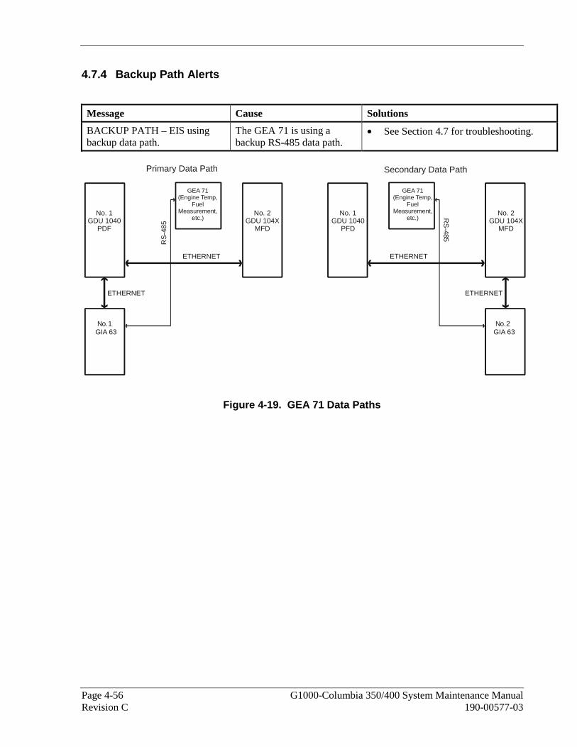
Page 4-56 G1000-Columbia 350/400 System Maintenance Manual Revision C 190-00577-03
4.7.4 Backup Path Alerts
Message Cause Solutions
BACKUP PATH – EIS using backup data path.
The GEA 71 is using a backup RS-485 data path.
• See Section 4.7 for troubleshooting.
ETHERNET ETHERNET
ETHERNET ETHERNET
RS
-485
RS
-485
GEA 71(Engine Temp,
FuelMeasurement,
etc.)
GEA 71(Engine Temp,
FuelMeasurement,
etc.)No. 1
GDU 1040PDF
No. 2GDU 104X
MFD
N No o. .1 2GIA 63 GIA 63
No. 2GDU 104X
MFD
No. 1GDU 1040
PFD
Secondary Data PathPrimary Data Path
Figure 4-19. GEA 71 Data Paths

G1000-Columbia 350/400 System Maintenance Manual Page 4-57 190-00577-03 Revision C
4.8 GTX Troubleshooting
4.8.1 GTX 33 Common Alerts
Message Cause Solutions
XPDR1 CONFIG – XPDR1 configuration error. Config service req’d.
The G1000 has detected a GTX 33 configuration mismatch.
• Perform a SET>ACTV configuration reset on the GTX Configuration page and verify the aircraft registration number is present.
• If error is still present, reload configuration files from a loader card.
If problem persists, replace master configuration module, check configuration module harness for faults and replace if necessary..
NOTE New Terrain/Obstacle cards, Jeppesen Aviation Database and other optional features (i.e. TAWS unlock card) will need to be replaced if the master configuration module is changed. The G1000 System ID number will change to a new number when installing a new master configuration module. The old Terrain and other cards will no longer work as they will remain locked to the old System ID number.
MANIFEST – GTX1 software mismatch. Communication Halted.
The system has detected an incorrect software version loaded in GTX 33.
• Load correct software version.
XPDR1 SRVC – XPDR1 needs service. Return unit for repair.
The G1000 has detected a failure in GTX 33. • Replace GTX 33.
XPDR1 FAIL – XPDR1 is inoperative.
GTX 33 is not responding. • Check communication paths between GTX and GIAs for faults, see Figure 4-20.
• Replace GTX 33.

Page 4-58 G1000-Columbia 350/400 System Maintenance Manual Revision C 190-00577-03
4.8.2 Backup Path Alerts
Message Cause Solutions
BACKUP PATH – Transponder using backup data path.
The GTX 33 is using a backup RS-232 data path.
• See Section 4.8 for troubleshooting.
ETHERNET ETHERNET
ETHERNET ETHERNET
RS-232GTX 33 GTX 33
GDU 1040PFD
No.1GIA 63
GDU 104XMFD
GDU 1040PFD
GDU 104XMFD
No.2GIA 63
RS-232
Secondary Data PathPrimary Data Path
Figure 4-20. GTX 33 Data Paths
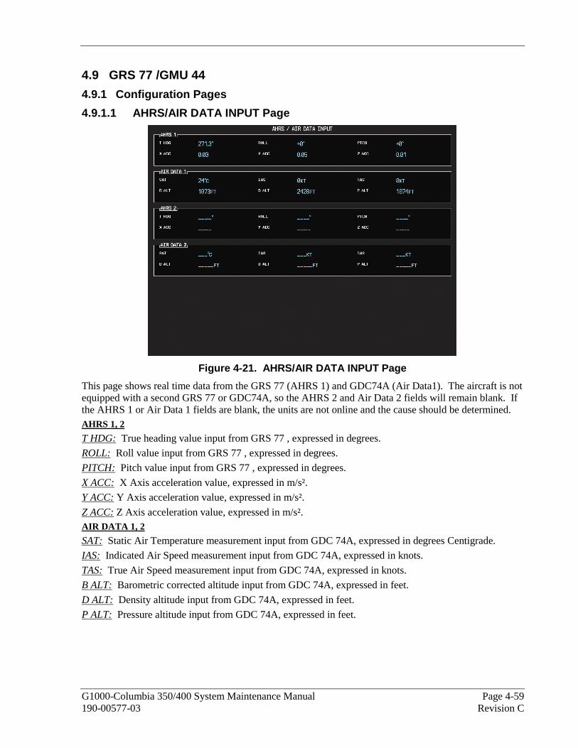
G1000-Columbia 350/400 System Maintenance Manual Page 4-59 190-00577-03 Revision C
4.9 GRS 77 /GMU 44
4.9.1 Configuration Pages
4.9.1.1 AHRS/AIR DATA INPUT Page
Figure 4-21. AHRS/AIR DATA INPUT Page
This page shows real time data from the GRS 77 (AHRS 1) and GDC74A (Air Data1). The aircraft is not equipped with a second GRS 77 or GDC74A, so the AHRS 2 and Air Data 2 fields will remain blank. If the AHRS 1 or Air Data 1 fields are blank, the units are not online and the cause should be determined. AHRS 1, 2
T HDG: True heading value input from GRS 77 , expressed in degrees.
ROLL: Roll value input from GRS 77 , expressed in degrees.
PITCH: Pitch value input from GRS 77 , expressed in degrees.
X ACC: X Axis acceleration value, expressed in m/s².
Y ACC: Y Axis acceleration value, expressed in m/s².
Z ACC: Z Axis acceleration value, expressed in m/s². AIR DATA 1, 2
SAT: Static Air Temperature measurement input from GDC 74A, expressed in degrees Centigrade.
IAS: Indicated Air Speed measurement input from GDC 74A, expressed in knots.
TAS: True Air Speed measurement input from GDC 74A, expressed in knots.
B ALT: Barometric corrected altitude input from GDC 74A, expressed in feet.
D ALT: Density altitude input from GDC 74A, expressed in feet.
P ALT: Pressure altitude input from GDC 74A, expressed in feet.

Page 4-60 G1000-Columbia 350/400 System Maintenance Manual Revision C 190-00577-03
4.9.2 Common Problems
Symptom Recommended Action
AHRS does not complete initialization
• Ensure that a cell phone or a device using cell phone technology is not turned on (even in a monitoring state) in the cabin.
• Ensure GPS has acquired at least four satellites, has a 3D navigation solution, and a DOP of less than 5.0. This is particularly important if this issue appears during ground operation only.
• Calibrate the GRS77.
• Check GRS 77 configuration module wiring for damage.
• Check GRS 77 connector for bent pins. If no damage can be found, replace GRS 77 configuration module. If problem persists, replace the GRS77.
Attitude appears unstable • Ensure that a cell phone or a device using cell phone technology is not turned on (even in a monitoring state) in the cabin.
• Ensure the four GRS 77 mounting screws are tight. Finger tight is not sufficient, a screwdriver must be used to verify.
• Ensure mounting rack and airframe shelf are secure and all hardware and brackets are present (CAUTION - do not loosen the mounting rack hardware to the airframe shelf or the aircraft will need to be leveled and the PITCH/ROLL OFFSET procedure performed)..
• Ensure aircraft battery is mounted securely if located near the GRS77. • Ensure GRS 77 connector is securely fastened and proper strain relief is
provided. • Remove GRS 77 connector and verify there are no bent pins.
• Replace the GRS77.
• Contact Garmin for further troubleshooting if required.

G1000-Columbia 350/400 System Maintenance Manual Page 4-61 190-00577-03 Revision C
4.9.3 Common Alerts
Message Cause Solutions
AHRS TAS – AHRS not receiving airspeed.
The GRS 77 is not receiving airspeed information from the GDC 74A.
• Check GRS/GDC interconnect for faults.
• Replace the GDC 74A with a known good unit:
If problem does not persist, replace the GRS 77 .
AHRS GPS – AHRS using backup GPS source.
The GRS 77 is using a backup GPS source.
AHRS GPS – AHRS not receiving backup GPS information.
The GRS 77 is not receiving backup GPS information from either GIA 63 .
AHRS GPS – AHRS operating exclusively in no-GPS mode.
The GRS 77 is operating in the absence of GPS.
AHRS GPS – AHRS not receiving any GPS information.
The GRS 77 is not receiving GPS data from the GPS receivers.
• Ensure that a cell phone or a device using cell phone technology is not turned on (even in a monitoring state) in the cabin.
• Check GPS status for GIA 1 and 2 on MFD - AUX GPS STATUS page. If one or both GPS receivers cannot acquire a position lock, see Section 4 for GPS troubleshooting.
• See Section 4.9 for data path troubleshooting.
• Replace the GRS 77 .
AHRS Service – AHRS magnetic field model needs updated.
The AHRS magnetic field model has expired.
• Reference SB 0533 for update instructions.
MANIFEST-GRS1 software mismatch. Communication Halted.
The system has detected an incorrect software version loaded in GRS 77 or the GMU 44.
• Load correct software version.

Page 4-62 G1000-Columbia 350/400 System Maintenance Manual Revision C 190-00577-03
4.9.4 Backup Path Alerts
Message Cause Solutions
BACKUP PATH – AHRS using backup data path.
The PFD is using a backup ARINC 429 data path to receive AHRS data.
• See 4.9.4 for troubleshooting.
GRS 77(Attitude,Heading)
ARINC 429
ETHERNET ETHERNET
ETHERNET ETHERNET
ARINC 429
ETHERNET ETHERNET
AR
INC
429 A
RIN
C429
No.1 No. 2
GIA 63 GIA 63
GDU 1040PFD
GDU 104XMFD
GDU 104XMFD
GDU 104XMFD
GDU 104XMFD
GDU 1040PFD
GDU 1040PFD
GDU 1040PFD
Primary Data Path Secondary Data Path
Third Data Path Fourth Data Path
GRS 77(Attitude,Heading)
GRS 77(Attitude,Heading)
GRS 77(Attitude,Heading)
Figure 4-22. GRS 77 Data Paths

G1000-Columbia 350/400 System Maintenance Manual Page 4-63 190-00577-03 Revision C
4.9.5 GMU Related Alerts
Message Cause Solutions
MANIFEST – GMU1 software mismatch. Communication Halted.
The system has detected an incorrect software version loaded in the GMU 44.
• Load correct software version.
HDG FAULT – A magnetometer fault has occurred.
A fault has occurred in the magnetometer.
• Check GMU 44/GRS 77 interconnect for faults.
• Replace the GMU 44. If problem persists, replace the GRS
77 .
4.10 GDC 74A
4.10.1 Common Problems
Symptom Recommended Action
Altitude is different than standby altimeter
• Perform a pitot/static check (see Columbia maintenance manual for procedure). Allow the GDC to warm up for fifteen minutes before checking accuracy, per Garmin Service Advisory 0606.
• Determine which instrument is outside limits and replace. The GDC is not field adjustable. Note: Both units may individually be in spec but show a difference in altitude. Do not return the GDC to Garmin for service if not outside limits.
GDC configuration file does not load.
• Replace GDC configuration module. If problem persists, replace GDC configuration module wire
harness. 4.10.2 GDC 74A Related Alerts
Message Cause Solutions
MANIFEST – GDC1 software mismatch. Communication Halted.
The system has detected an incorrect software version loaded in the GDC 74A.
• Load correct software version.

Page 4-64 G1000-Columbia 350/400 System Maintenance Manual Revision C 190-00577-03
4.10.3 Backup Path Alerts
Message Cause Solutions
BACKUP PATH – Airdata using backup data path.
The GDC 74A is using a backup ARINC 429 data path.
• See Section 4.10 for troubleshooting.
GDC 74A(Altitude,airspeed,vertical
speed, OAT)
ARINC 429
ETHERNET ETHERNET
ETHERNET ETHERNET
ARINC 429
ETHERNET ETHERNET
AR
INC
429 A
RIN
C429
No.1 No. 2
GIA 63 GIA 63
No. 1GDU 1040
PFD
No. 1GDU 104X
MFD
Primary Data Path Secondary Data Path
Third Data Path Fourth Data Path
No. 1GDU 1040
PFD
No. 1GDU 104X
MFD
No. 1GDU 1040
PFD
No. 1GDU 104X
MFD
No. 1GDU 1040
PFD
No. 1GDU 104X
MFD
GDC 74A(Altitude,airspeed,vertical
speed, OAT)
GDC 74A(Altitude,airspeed,vertical
speed, OAT)
GDC 74A(Altitude,airspeed,vertical
speed, OAT)
Figure 4-23. GDC 74A Data Paths

G1000-Columbia 350/400 System Maintenance Manual Page 4-65 190-00577-03 Revision C
4.11 GDL 69/69A Configuration Pages
4.11.1 GDL 69 Page
Figure 4-24. GDL 69 Page
NOTE
Refer to Service Bullitens 0538 and 0544 when troubleshooting a GDL 69/69A.
Configuration settings are not field adjustable.
AUDIO RADIO refers to XM audio receiver installed in the GDL 69A, DATA RADIO refers to the XM data receiver installed in both the GDL 69 and GDL 69A.
CONFIGURATION
SELECT GDL ANTENNA: Selects the GDL antenna.
UPPER BOUND ANTENNA GAIN (NOMINAL dB): Sets the upper bound antenna gain value.
LOWER BOUND ANTENNA GAIN (NOMINAL dB): Sets the lower bound antenna gain value.
CABLE LOSS INCLUDING INLINE ATTENUATIONS IF USED (NOMINAL dB): Sets the inline cable loss attenuation value.
DESIRED YODA MODULE GAIN (NOMINAL dB): Sets the desired YODA module gain.
GDL CONFIGURABLE ATTENUATION (dB): Sets the desired GDL attenuation value.
ETHERNET PORT 2, 3, 4: Enables and/or disables the desired Ethernet port.

Page 4-66 G1000-Columbia 350/400 System Maintenance Manual Revision C 190-00577-03
DATA
ID: Displays the identification number for the GDL 69/69A.
ACTIVE: Displays the active status for the GDL 69/69A.
SIGNAL: Displays the signal level for the GDL 69/69A.
0 – no signal
1 – weak signal
2 – adequate signal
3 – good signal
NOTE
Levels 2 and 3 should allow for proper operation of all GDL69/69A audio and weather options. Levels 0 and 1 are likely indications of problems with availablity. A “204” message in the signal field indicates that signal information has not initialized.
DIAGNOSTICS (For XM use only, not useful for troubleshooting)
QUALITY OF SERVICE: Displays the quality of service for the GDL 69/69A.
TERRESTRIAL ERROR STATUS: Displays the terrestrial error status for the GDL 69/69A.
SATELLITE 1 ERROR: Displays the error status for satellite 1.
SATELLITE 2 ERROR: Displays the error status for satellite 2.
TUNER STATUS: Displays the tuner status for the GDL 69/69A.

G1000-Columbia 350/400 System Maintenance Manual Page 4-67 190-00577-03 Revision C
4.11.2 Common Problems
Symptom Recommended Action
No XM audio is heard
No XM weather information is displayed
• Ensure the following items are not preventing the audio panel from distributing XM audio (reference applicable G1000 Pilot’s Guide):
Verify the XM volume is not muted on the AUX – XM RADIO page on the MFD.
Verify no music sources are plugged into the AUX music input jack.
Verify the COM squelch is not open. Verify the ICS squelch is not open. Verify the marker beacon tones are not being received. Verify the headphone (if equipped) volume is turned up.
• Go to the AUX – SYSTEM STATUS page on the MFD and ensure unit is online.
If a red X is present, verify the unit is receiving power at the rack connector.
• Ensure there are no GDL alerts in the alert window. If there is an Alert for software or configuration error or mismatch, reload the file noted in the Alert.
• Restart the PFD and MFD in configuration mode and go to the GDL page.
Verify unit is active. Verify the Signal number is “2” or “3”. If it is “0” or “1” check the
GDL 69/69A antenna and cabling for faults. o Reseat the GDL 69/69A to verify the coax connector is fully
seated. If unit is not active, contact XM Customer service at 1-800-985-
9200 to have a refresh signal sent to your unit. You will need to provide them the Audio Radio ID (and Data Radio ID number for XM weather) numbers. Also verify with XM that the correct Weather package (Aviator Lite or Aviator) is on the account, and that no traffic service has been activated against that Radio ID. The unit must be on for approximately one hour after the request for the refresh has been sent to receive the signal. o Alternatively, you may also go to XM’s website at
http://www.xmradio.com/refresh/ and enter the radio IDs to have a refresh signal sent.
If there is still problems receiving weather products after performing the above step, call XM and have the account deactivated, and a new account activated to clear out any corrupt account information.
• Verify there is a good ground connection through the aircraft between the MFD and the GDL69/69A unit. Reference the Aircraft Maintenance Manual for instructions on how to check bonding and ground points.
If problem persists, replace the GDL 69/69A.

Page 4-68 G1000-Columbia 350/400 System Maintenance Manual Revision C 190-00577-03
4.11.3 GDL 69/69A Related Alerts
Message Cause Solutions
GDL 69 FAIL – GDL 69 has failed.
The G1000 has detected a failure in the GDL 69/69A.
• Replace GDL 69A.
• Check GDL 69A antenna and cabling. • Check the GDL 69A and MFD
interconnect.
GDL69 CONFIG – GDL 69 configuration error. Config service req’d.
The G1000 has detected a GDL 69A configuration mismatch.
• Reload GDL configuration files. If problem persists, replace master
configuration module, check configuration module harness for faults and replace if necessary.
NOTE New Terrain/Obstacle cards, Jeppesen Aviation Database and other optional features (i.e. TAWS unlock card) will need to be replaced if the master configuration module is changed. The G1000 System ID number will change to a new number when installing a new master configuration module. The old Terrain and other cards will no longer work as they will remain locked to the old System ID number.
MANIFEST – GDL software mismatch. Communication halted.
The system has detected an incorrect software version loaded in GDL 69A.
• Load correct software version.
GDL 69ADATA LINK
ETHERNET
No. 1GDU 1040
PFD
No. 1GDU 104X
MFD
Primary Data Path
Figure 4-25. GDL 69 Data Paths

G1000-Columbia 350/400 System Maintenance Manual Page 4-69 190-00577-03 Revision C
4.11.4 GCU 476 Troubleshooting
Failure Message Cause Solutions MANIFEST – GCU software mismatch. Communication Halted.
The system has detected an incorrect software version loaded into the GCU 476.
• Reload software. See Section 6.11.1 for GCU 476 Software Load Procedure.
GCU CONFIG - GCU config error. Config service req'd.
The system has detected a GCU configuration mismatch.
• See Section 6.11 for GCU 476 Configuration Procedure.
GCU FAIL – The GCU 476 has failed.
The system has detected a failure in the GCU 476.
• Ensure GCU 476 is receiving power.
• Check GCU wiring. • Replace GCU 476 if problem
persists.
GCU PATH – A GCU path has failed.
The system has detected a path from the GCU 476 to the PFD or MFD is bad.
• Check GCU wiring. • Check status of GCU-MFD1
and GCU-PFD1 in configuration mode on the system status page.
• Replace the display.
GCU 476
RS-232
No. 1GDU 1040
PFD
No. 1GDU 104X
MFD
Primary Data Path
RS-232
ETHERNET
GIA #2GIA #1
ETHERNET
Figure 4-26. GCU 476 Data Paths

Page 4-70 G1000-Columbia 350/400 System Maintenance Manual Revision C 190-00577-03
4.12 GFC 700
4.12.1 Configuration Pages
4.12.1.1 GFC Configuration Page
Figure 4-27. GFC CONFIGURATION Page
All settings are contained in the GFC configuration file.
CAUTION
The data contained on this page is extremely critical to aircraft safety.
SELECT GIA UNIT
This window shows the currently selected GIA. CONFIGURATION
FD COMMAND BARS: Selects the type of flight director command bars.
FD TIME CONSTANT: Selects the flight director time constant.
AP DISC REMOVES FD: Turns the autopilot disconnect removes flight director function on or off.
AP DISC ALERT: Turns the approach disconnect alert on or off.
PITCH SERVO: Shows the currently selected pitch servo.
ROLL SERVO: Shows the currently selected roll servo.
YAW SERVO: Shows the currently selected yaw servo.
PITCH TRIM SERVO: Shows the currently selected pitch trim servo.
ROLL TRIM SERVO: Shows the currently selected roll trim servo.
YAW TRIM SERVO: Shows the currently selected yaw trim servo.
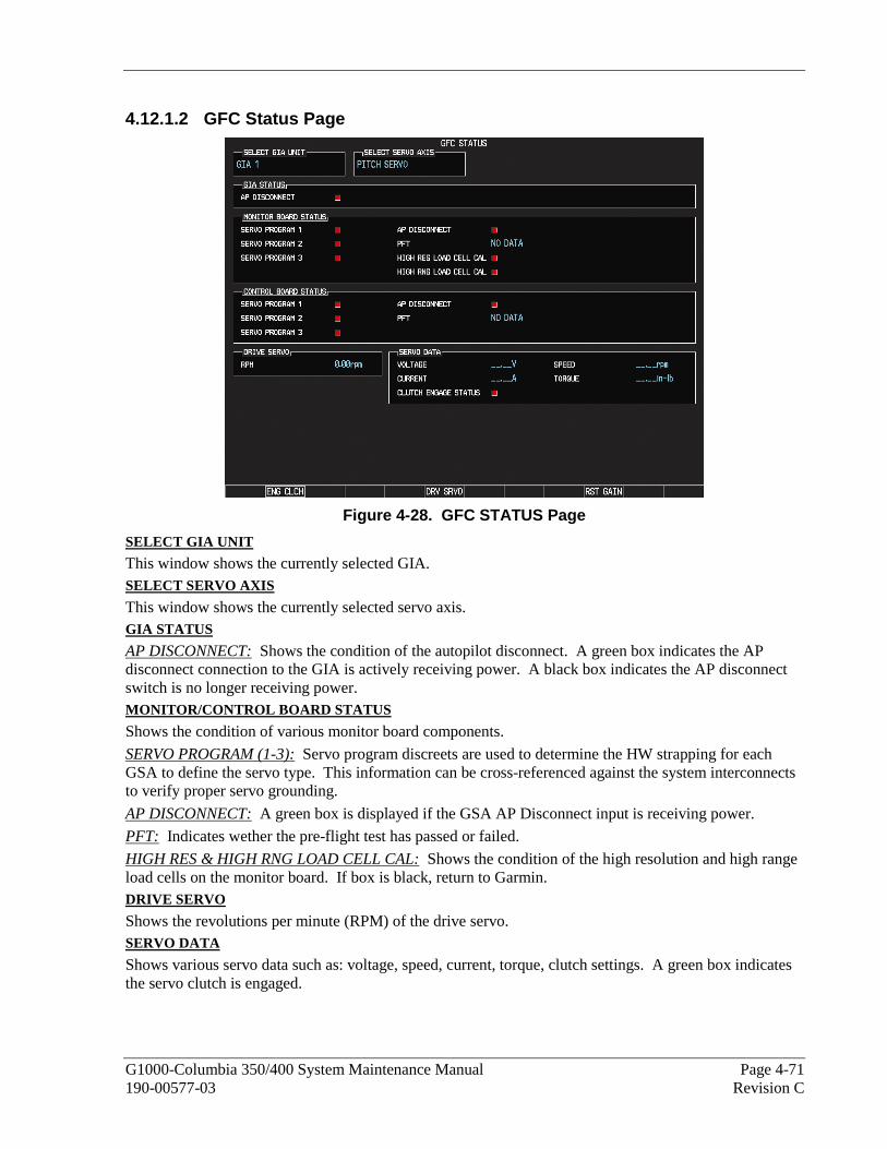
G1000-Columbia 350/400 System Maintenance Manual Page 4-71 190-00577-03 Revision C
4.12.1.2 GFC Status Page
Figure 4-28. GFC STATUS Page
SELECT GIA UNIT
This window shows the currently selected GIA. SELECT SERVO AXIS
This window shows the currently selected servo axis. GIA STATUS
AP DISCONNECT: Shows the condition of the autopilot disconnect. A green box indicates the AP disconnect connection to the GIA is actively receiving power. A black box indicates the AP disconnect switch is no longer receiving power. MONITOR/CONTROL BOARD STATUS
Shows the condition of various monitor board components.
SERVO PROGRAM (1-3): Servo program discreets are used to determine the HW strapping for each GSA to define the servo type. This information can be cross-referenced against the system interconnects to verify proper servo grounding.
AP DISCONNECT: A green box is displayed if the GSA AP Disconnect input is receiving power.
PFT: Indicates wether the pre-flight test has passed or failed.
HIGH RES & HIGH RNG LOAD CELL CAL: Shows the condition of the high resolution and high range load cells on the monitor board. If box is black, return to Garmin. DRIVE SERVO
Shows the revolutions per minute (RPM) of the drive servo. SERVO DATA
Shows various servo data such as: voltage, speed, current, torque, clutch settings. A green box indicates the servo clutch is engaged.
Page 4-72 G1000-Columbia 350/400 System Maintenance Manual Revision C 190-00577-03
4.12.2 GFC 700 Pre-Flight Test Sequence and Troubleshooting
This section was created to help determine why the GFC700 has failed the Pre-Flight Test indicated by
the PFT red annunciation - . It defines the PFT sequence for the servos and the GFC 700 system and then provides troubleshooting information to help resolve failures.
There are 16 steps to the GFC700 PFT. The PFT is performed by both GIAs at startup, and needs to pass on both GIAs before the autopilot can be engaged.
The PFT is only started if the AHRS has aligned, the GIAs and servos are configured and the certification gains are valid. If the PFT has not completed after one minute from when the initialization started, the PFT will fail. After the system PFT has passed, it will be performed again if a servo resets, if the autopilot servo breaker is reset or the cross side GIA restarts it.
Generally, the PFT failure fault is logged in the GIA Maintenance Log and not in the Servo Maintenance Logs unless the GIA log fault identifies a servo problem.
NOTE
A thorough understanding of operating and understanding the G1000 system in Configuration mode is recommended before you start this procedure.
To access the GIA and GSA Maintenance Logs, perform the following steps –
1. Start the G1000 in Configuration mode.
2. Use the FMS knob on the PFD to go to the Diagnostics Terminal page in the System group. This page allows the technician to view maintenance logs associated with the GFC 700.
3. Choose “GIA 1” or “GIA 2” in the LRU window.
4. In the SERVO window, choose “NONE” to view the GIA Maintenance Log, or choose a servo to view their logs.
5. Using the FMS knob, choose “VIEW MAINTENANCE LOG” in the COMMAND window.
6. Press the ENT key.
7. Scroll through the OUTPUT list by pressing the OUTPUT softkey to view the stored faults.
The GIA Maintenance Log can record any of the following faults:
• FCS Task not started: Bad gains
The FCS task has not started because the gains are not present or have been corrupted.
Reload the gain files to correct.
• FCS Task not started: Gain structure out of range
The FCS task has not started because the gains are not compatible with the GIA software.
Reload the gain files to correct.
• PFT FAIL: Timeout, <STEP>
Pre-flight test has failed because the specified step has not passed in the allotted time. See the GIA pre-flight steps for a description of the possible values for <STEP> on the failed GIA and corrective actions.
• PFT FAIL: Cross GIA Failed, State: <STEP> Pre-flight test has failed on opposite GIA. <STEP> specifies the pre-flight test step on selected GIA that was in progress when the pre-flight test failed on the opposite GIA. See the GIA pre-flight steps for a description of the possible values for <STEP> on the failed GIA and corrective actions.

G1000-Columbia 350/400 System Maintenance Manual Page 4-73 190-00577-03 Revision C
• PFT FAIL: <STEP>
Pre-flight has failed because the step specified has failed. See the GIA pre-flight test steps for a description of the possible values for <STEP> on the failed GIA and corrective actions.
• AHRS MON invalid: <STATE>
The AHRS monitor has detected that the AHRS data is invalid. The possible values for <STATE> are:
a. Mon Prmtr Invalid: The ARINC 429 data used by one of the monitors has not been received.
b. Attitude Prmtr Invalid: The ARINC 429 pitch or roll angle has not been received.
c. Exceeded Attitude Limits: The pitch or roll angle has exceeded the engagement limits.
d. Cross Hdg Accel Fail: Cross heading acceleration monitor failed.
e. Vert Accel Fail: Vertical acceleration monitor failed.
f. Fltrd Cross Hdg Accel Fail: Filtered cross heading acceleration monitor failed.
g. Fltrd Vert Accel Fail: Filtered vertical acceleration monitor failed.
h. Roll Accel Fail: Roll acceleration monitor has failed.
i. Normal Accel Fail: Normal acceleration has failed.
Troubleshoot the GRS 77 for the cause of the failure.
• Stuck switch invalidated parameter: <AXIS>
A MET switch in the specified axis is stuck.
Check the MET (trim) switches for proper operation.
• PRMTR: <PARAMETER> MODE:<MODE> Parameter lost The mode specified by <MODE> has been disengaged because the parameter specified by <PARAMETER> has become invalid. The following is a list of some of the possible values for <PARAMETER>:
a. AD TDM Comm Valid: The specified mode has been disengaged because communication with the servos, via the Time Division Multiplexer protocol, has been lost.
b. AP Pitch MET not stuck: The specified mode has been disengaged due to a stuck pitch MET switch.
Check the MET (trim) switches for proper identification.
4.12.2.1 GIA Pre-Flight Test Steps
• PFT Step 0: System initializing, verify GFC powered This step checks to ensure the GFC is powered up.
Ensure the GIA is connected to the autopilot disconnect on the GFC Configuration page.
Ensure all configured servos are communicating on the System Status page.
• PFT Step 1: System initializing, verify GIA audio is valid This step checks to ensure the GIA audio region has been loaded and configured.
Load GIA audio files to correct.
• PFT Step 2: System initializing, verify required servos are configured This step checks to ensure the current servo configuration matches the servo configuration specified in the certification gain file.
Reload the gain files to correct.

Page 4-74 G1000-Columbia 350/400 System Maintenance Manual Revision C 190-00577-03
• PFT Step 3: System initializing, verify selected side This step checks to ensure the PFD is online and sending the selected AFCS side data over HSDB to the GIA.
Ensure the PFD is turned on.
Ensure the Ethernet connection from the PFD to the GIA is functioning.
• PFT Step 4: System initializing, verify AHRS monitor This step checks to ensure the AHRS monitor is valid and not reporting an AHRS failure. NOTE: AHRS monitor will be assumed valid if on the ground.
Ensure the GRS 77 and GDC 74 are turned on and sending valid data.
• PFT Step 5: System initializing, verify configured servos are valid This step checks to ensure that none of the servos are reporting any type of failure. Note that trim servos will report a failure on stuck MET switches.
Ensure MET switch is not stuck.
Cycle power on all servos.
• PFT Step 6: System initializing, verify cross GIA valid This step checks to ensure the cross-side GIA is online and communicating with all servos from ARINC 485 data lines. The cross-side GIA must also pass its AHRS monitoring.
Ensure both GIAs are online and communicating with all servos.
• PFT Step 7: Verify cross GIA initialized This step checks to ensure the cross-side GIA is initialized.
Cycle power on all servos and GIAs.
Ensure the PFD and MFD are turned on.
• PFT Step 8: Verify servo type This step checks to ensure the servos are correct type.
Verify servos are correct type.
• PFT Step 9: Verify servo first certification data This step checks to ensure the servos and the GIAs have the same certification gains.
Reload the certification gains to all GIAs and servos.
• PFT Step 10: Verify servo second certification data This step checks to ensure the servos and the GIAs have the same certification gains.
Reload the certification gains to all GIAs and servos.
• PFT Step 11: Updating servo RTC This step sets the servo system time to the GIA system time.
• PFT Step 12: Verify servo PFT status This step checks to ensure all servos have passed their own pre-flight test.
• PFT Step 13: Verify AP disconnect enabled This step checks to ensure GIA 1, GIA 2, and all servos are connected to the 28 volt autopilot disconnect.
Ensure the autopilot disconnect is connected to all GIAs and servos and is registering 28 volts.
Ensure the autopilot disconnect switch is not pressed.

G1000-Columbia 350/400 System Maintenance Manual Page 4-75 190-00577-03 Revision C
• PFT Step 14: Verify servo validity This step checks to ensure all servos are online and communicating with valid data.
Ensure all servos are turned on and communicating.
• PFT Step 15: Verify cross GIA PFT is completed This step checks to ensure the cross-side GIA is also on step 14.
Cycle power on all servos and GIAs.
Ensure the PFD and MFD are turned on.
• PFT Step 16: PFT completed The pre-flight test is successfully completed.
• PFT Step 17: PFT failed The pre-flight test has failed.
4.12.2.2 Servo Faults and Troubleshooting
Whenever a servo fault occurs, a status message is logged to the corresponding servo control or monitor maintenance log. This information is also accompanied by a time and date stamp. An “RTC DATE” entry is made every time a servo is powered on, it is normally not useful for troubleshooting.
The following is a listing of possible faults that could be reported in a GSA fault log. Faults can occur in either the monitor board processor or the control board processor, both of which are contained in the GSA unit.
Monitor Processor
The monitor processor contains the logs that are found in these processors -
2 – Pitch Servo
4 – Roll Servo
8 – Pitch Trim Servo
There are two main groupings of faults that can occur in the monitor processor.
The first grouping of faults can occur during the GSA unit pre-flight test (PFT). If there is a fault during PFT the unit will not be able to transition to normal mode and the only way to clear this state would be to cycle unit power.
The second grouping of faults can occur during normal mode. These faults generally cause a disconnect of power to the GSA and report that a fault has occurred to the GIA.
The Notes column indicates any actions that can be taken to troubleshoot the problem in the aircraft by the technician. Any faults that are not listed here indicate an internal problem requiring replacement of the servo. If the items in the Notes column check out ok, replace the servo.
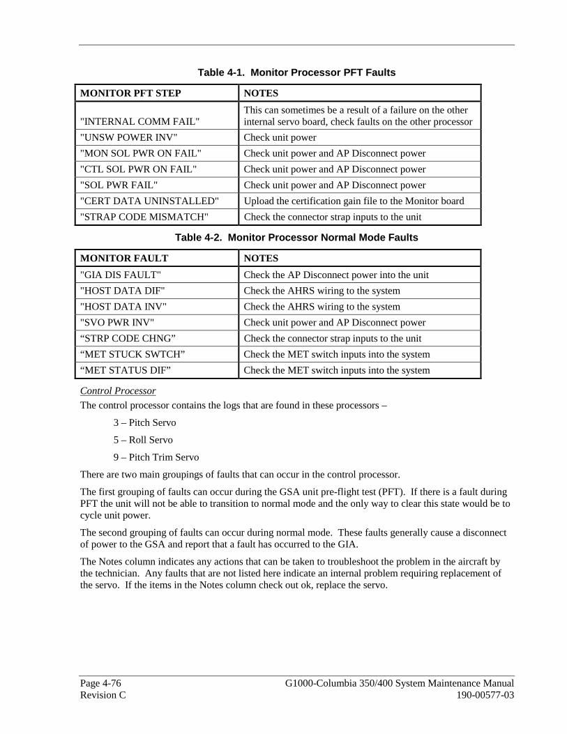
Page 4-76 G1000-Columbia 350/400 System Maintenance Manual Revision C 190-00577-03
Table 4-1. Monitor Processor PFT Faults
MONITOR PFT STEP NOTES
"INTERNAL COMM FAIL" This can sometimes be a result of a failure on the other internal servo board, check faults on the other processor
"UNSW POWER INV" Check unit power
"MON SOL PWR ON FAIL" Check unit power and AP Disconnect power
"CTL SOL PWR ON FAIL" Check unit power and AP Disconnect power
"SOL PWR FAIL" Check unit power and AP Disconnect power
"CERT DATA UNINSTALLED" Upload the certification gain file to the Monitor board
"STRAP CODE MISMATCH" Check the connector strap inputs to the unit
Table 4-2. Monitor Processor Normal Mode Faults
MONITOR FAULT NOTES
"GIA DIS FAULT" Check the AP Disconnect power into the unit
"HOST DATA DIF" Check the AHRS wiring to the system
"HOST DATA INV" Check the AHRS wiring to the system
"SVO PWR INV" Check unit power and AP Disconnect power
“STRP CODE CHNG” Check the connector strap inputs to the unit
“MET STUCK SWTCH” Check the MET switch inputs into the system
“MET STATUS DIF” Check the MET switch inputs into the system
Control Processor
The control processor contains the logs that are found in these processors –
3 – Pitch Servo
5 – Roll Servo
9 – Pitch Trim Servo
There are two main groupings of faults that can occur in the control processor.
The first grouping of faults can occur during the GSA unit pre-flight test (PFT). If there is a fault during PFT the unit will not be able to transition to normal mode and the only way to clear this state would be to cycle unit power.
The second grouping of faults can occur during normal mode. These faults generally cause a disconnect of power to the GSA and report that a fault has occurred to the GIA.
The Notes column indicates any actions that can be taken to troubleshoot the problem in the aircraft by the technician. Any faults that are not listed here indicate an internal problem requiring replacement of the servo. If the items in the Notes column check out ok, replace the servo.

G1000-Columbia 350/400 System Maintenance Manual Page 4-77 190-00577-03 Revision C
Table 4-3. Control Processor PFT Faults
CONTROL PFT STEP NOTES
"INT COMM TEST FAIL" This can sometimes be a result of a failure on the other board, check faults on other processor
"CTL MOT PWR ON FAIL" Check unit power and AP Disconnect power
"MON MOT PWR ON FAIL" Check unit power and AP Disconnect power
"HALL 1 FAIL" Check unit power and AP Disconnect power
"HALL 2 FAIL" Check unit power and AP Disconnect power
"HALL 3 FAIL" Check unit power and AP Disconnect power
"HALL 4 FAIL" Check unit power and AP Disconnect power
"HALL 5 FAIL" Check unit power and AP Disconnect power
"HALL 6 FAIL" Check unit power and AP Disconnect power
"CURR OFFST FAIL" Check unit power and AP Disconnect power
"SVO TYPE FAIL" Check unit power and AP Disconnect power
"CERT DATA UNINSTALLED"
Upload the certification gain file to the Control board
"STRAP CODE MISMATCH" Check the connector strap inputs to the unit
Table 4-4. Control Processor Normal Mode Faults
CONTROL FAULT NOTES
"GIA DIS FAULT" Check the AP Disconnect power into the unit
"HOST DATA DIF" Check the AHRS wiring to the system
"HOST DATA INV" Check the AHRS wiring to the system
"SVO PWR INV" Check unit power and AP Disconnect power
“STRP CODE CHNG” Check the connector strap inputs to the unit
“MET STUCK SWTCH” Check the MET switch inputs into the system
“MET STATUS DIF” Check the MET switch inputs into the system
4.12.2.3 Downloading GIA and GSA Maintenance Logs
If additional assistance is needed troubleshooting autopilot faults, the Maintenance logs can be downloaded to an SD card as a text file (.txt) and emailed to Garmin Aviation Product Support at [email protected]. Please call Garmin Aviation Product Support before you send a Maintenance Log to notify them you are sending it to prevent a delay in response. You may download multiple GIA and GSA Maintenance Logs to the same file, however in your email to Garmin you must furnish the order in which they were downloaded (i.e. GIA1, then GIA2, then SRVO PTCH MON, then SRVO PTCH CTL, etc.).
1. Insert a FAT 32 formatted SD card into the top slot of the PFD before turning on the displays.
2. Power up PFD and MFD in the configuration mode.
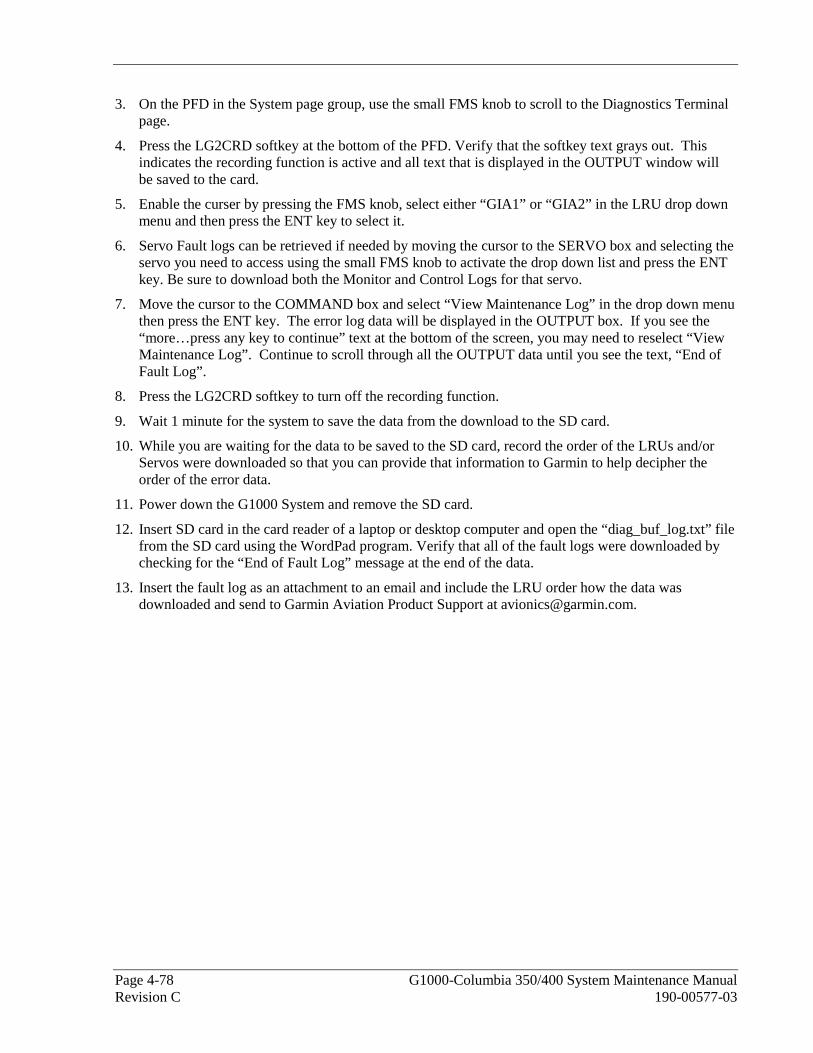
Page 4-78 G1000-Columbia 350/400 System Maintenance Manual Revision C 190-00577-03
3. On the PFD in the System page group, use the small FMS knob to scroll to the Diagnostics Terminal page.
4. Press the LG2CRD softkey at the bottom of the PFD. Verify that the softkey text grays out. This indicates the recording function is active and all text that is displayed in the OUTPUT window will be saved to the card.
5. Enable the curser by pressing the FMS knob, select either “GIA1” or “GIA2” in the LRU drop down menu and then press the ENT key to select it.
6. Servo Fault logs can be retrieved if needed by moving the cursor to the SERVO box and selecting the servo you need to access using the small FMS knob to activate the drop down list and press the ENT key. Be sure to download both the Monitor and Control Logs for that servo.
7. Move the cursor to the COMMAND box and select “View Maintenance Log” in the drop down menu then press the ENT key. The error log data will be displayed in the OUTPUT box. If you see the “more…press any key to continue” text at the bottom of the screen, you may need to reselect “View Maintenance Log”. Continue to scroll through all the OUTPUT data until you see the text, “End of Fault Log”.
8. Press the LG2CRD softkey to turn off the recording function.
9. Wait 1 minute for the system to save the data from the download to the SD card.
10. While you are waiting for the data to be saved to the SD card, record the order of the LRUs and/or Servos were downloaded so that you can provide that information to Garmin to help decipher the order of the error data.
11. Power down the G1000 System and remove the SD card.
12. Insert SD card in the card reader of a laptop or desktop computer and open the “diag_buf_log.txt” file from the SD card using the WordPad program. Verify that all of the fault logs were downloaded by checking for the “End of Fault Log” message at the end of the data.
13. Insert the fault log as an attachment to an email and include the LRU order how the data was downloaded and send to Garmin Aviation Product Support at [email protected].

G1000-Columbia 350/400 System Maintenance Manual Page 4-79 190-00577-03 Revision C
4.13 Backshell Connectors The following figures depict the backshell connectors as viewed with the LRU removed.
1 2 3
16 17
4 5 6 7 8 9 10 111213 1415
1819 20 21222324 2526 2728 293031 323334 353637 38394041 4243 44
1 2 3 4 5 6 7 8 9 10 11 12 13 14 15 16 17 18 19 20
21 22 23 24 25 26 27 28 29 30 31 32 33 34 35 36 37 38 39
40 41 42 43 44 45 46 47 48 49 50 51 52 53 54 55 56 57 58 59
60 61 62 63 64 65 66 67 68 69 70 71 72 73 74 75 76 77 78
1 2 3 4 5 6 7 8 9 10 11 12 13 14 15 16 17 18 19 20
21 22 23 24 25 26 27 28 29 30 31 32 33 34 35 36 37 38 39
40 41 42 43 44 45 46 47 48 49 50 51 52 53 54 55 56 57 58 59
60 61 62 63 64 65 66 67 68 69 70 71 72 73 74 75 76 77 78
COM BOARD CONNECTOR (P601)
COM ANTENNA CONNECTORCOOLING PORT
MAIN DISCRETE CONNECTOR (P604)
MAIN SERIAL CONNECTOR (P603)
GPS ANTENNA CONNECTOR
I/O CONNECTOR #2 (P606) I/O CONNECTOR #1 (P605)
G/S ANTENNA CONNECTOR
NAV ANTENNA CONNECTORVOR/ILS CONNECTOR (P602)
Figure 4-29. GIA 63 Backshell Connectors
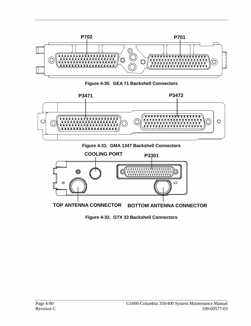
Page 4-80 G1000-Columbia 350/400 System Maintenance Manual Revision C 190-00577-03
1 2 3 4 5 6 7 8 9 10 11 12 13 14 15 16 17 18 19 20
21 22 23 24 25 26 27 28 29 30 31 32 33 34 35 36 37 38 39
40 41 42 43 44 45 46 47 48 49 50 51 52 53 54 55 56 57 58 59
60 61 62 63 64 65 66 67 68 69 70 71 72 73 74 75 76 77 78
P702 P701
Figure 4-30. GEA 71 Backshell Connectors
1 2 3 4 5 6 7 8 9 10 11 12 13 14 15 16 17 18 19 20
21 22 23 24 25 26 27 28 29 30 31 32 33 34 35 36 37 38 39
40 41 42 43 44 45 46 47 48 49 50 51 52 53 54 55 56 57 58 59
60 61 62 63 64 65 66 67 68 69 70 71 72 73 74 75 76 77 78
P3471 P3472
Figure 4-31. GMA 1347 Backshell Connectors
1 2 3 4 5 6 7 8 9 10 11 12 13 14 15 16 1718 19 20 21
22 23 24 25 26 2728 29 30 31 32 33 34 35 36 3738 39 40 4142
43 44 45 46 47 48 49 50 51 52 53 54 55 5657 58 59 60 61 62
TOP ANTENNA CONNECTOR BOTTOM ANTENNA CONNECTOR
P3301COOLING PORT
Figure 4-32. GTX 33 Backshell Connectors

G1000-Columbia 350/400 System Maintenance Manual Page 4-81 190-00577-03 Revision C
Figure 4-33. GDU 1040/42/44 Backshell Connector (P10001)
Figure 4-34. GRS 77 Backshell Connector (P771)
Figure 4-35. GDC 74A Backshell Connector (P741)
Figure 4-36. GCU 476 Backshell Connector (P4751)
Figure 4-37. GDL 69/69A Backshell Connector (P691)

Page 4-82 G1000-Columbia 350/400 System Maintenance Manual Revision C 190-00577-03
This Page Intentionally Left Blank

G1000-Columbia 350/400 System Maintenance Manual Page 5-1 190-00577-03 Revision C
5 G1000 EQUIPMENT REMOVAL AND REPLACEMENT This section describes how to remove and replace G1000 equipment in the Columbia 350/400. After removal and replacement, LRUs must be configured and tested as described in Section 6.
CAUTION
When removing and/or replacing any G1000 component, always ensure that aircraft power is off. Unplug any auxiliary power supplies.
Before removing any G1000 LRU, it is required that the technician verify the LRU software part number and version against the Required Equipment List.
To check an LRU software part number and/or version:
1. Start the G1000 system in configuration mode as described in Section 3.4.
2. The System Status page shows a list of LRUs in the LRU window. Activate the cursor and highlight the LRU window.
3. Use the FMS knob to scroll through the list in the window and select the desired LRU.
4. The software part number and version is displayed in the DATA window. Compare this to the data in the Required Equipment List.
NOTE
If a faulty LRU is not reporting its software version and part number, check aircraft maintenance logs for last software version loaded and verify against the Required Equipment List. The Software Manifest page may also be used to check part numbers and versions.
Figure 5-1. System Status Page (Configuration Mode)
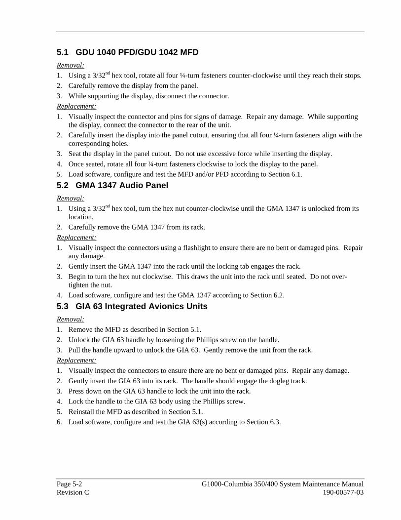
Page 5-2 G1000-Columbia 350/400 System Maintenance Manual Revision C 190-00577-03
5.1 GDU 1040 PFD/GDU 1042 MFD Removal:
1. Using a 3/32nd hex tool, rotate all four ¼-turn fasteners counter-clockwise until they reach their stops.
2. Carefully remove the display from the panel.
3. While supporting the display, disconnect the connector.
Replacement:
1. Visually inspect the connector and pins for signs of damage. Repair any damage. While supporting the display, connect the connector to the rear of the unit.
2. Carefully insert the display into the panel cutout, ensuring that all four ¼-turn fasteners align with the corresponding holes.
3. Seat the display in the panel cutout. Do not use excessive force while inserting the display.
4. Once seated, rotate all four ¼-turn fasteners clockwise to lock the display to the panel.
5. Load software, configure and test the MFD and/or PFD according to Section 6.1.
5.2 GMA 1347 Audio Panel Removal:
1. Using a 3/32nd hex tool, turn the hex nut counter-clockwise until the GMA 1347 is unlocked from its location.
2. Carefully remove the GMA 1347 from its rack.
Replacement:
1. Visually inspect the connectors using a flashlight to ensure there are no bent or damaged pins. Repair any damage.
2. Gently insert the GMA 1347 into the rack until the locking tab engages the rack.
3. Begin to turn the hex nut clockwise. This draws the unit into the rack until seated. Do not over-tighten the nut.
4. Load software, configure and test the GMA 1347 according to Section 6.2.
5.3 GIA 63 Integrated Avionics Units Removal:
1. Remove the MFD as described in Section 5.1.
2. Unlock the GIA 63 handle by loosening the Phillips screw on the handle.
3. Pull the handle upward to unlock the GIA 63. Gently remove the unit from the rack.
Replacement:
1. Visually inspect the connectors to ensure there are no bent or damaged pins. Repair any damage.
2. Gently insert the GIA 63 into its rack. The handle should engage the dogleg track.
3. Press down on the GIA 63 handle to lock the unit into the rack.
4. Lock the handle to the GIA 63 body using the Phillips screw.
5. Reinstall the MFD as described in Section 5.1.
6. Load software, configure and test the GIA 63(s) according to Section 6.3.

G1000-Columbia 350/400 System Maintenance Manual Page 5-3 190-00577-03 Revision C
5.4 GEA 71 Engine/Airframe Unit Removal:
1. Remove the PFD as described in Section 5.1.
2. Unlock the GEA 71 handle by unscrewing the Phillips screw.
3. Pull the handle upward to unlock the GEA 71. Gently remove the GEA 71 from its rack.
Replacement:
1. Visually inspect the connectors to ensure there are no bent or damaged pins. Repair any damage.
2. Gently insert the GEA 71 into the rack. The handle should engage the dogleg track.
3. Press down on the handle to lock the unit into place.
4. Lock the handle to the GEA 71 body using the Phillips screw.
5. Reinstall the PFD as described in Section 5.1.
6. Load software, configure and test the GEA 71 according to Section 6.4.
5.5 GTX 33 Transponder Removal:
1. Remove the PFD as described in Section 5.1.
2. Unlock the GTX 33 handle by loosening the Phillips screw on the handle.
3. Pull the handle upward to unlock the GTX 33. Gently remove the unit from the rack.
Replacement:
1. Visually inspect the connectors to ensure there are no bent or damaged pins. Repair any damage.
2. Gently insert the GTX 33 into its rack. The handle should engage the dogleg track.
3. Press down on the GTX 33 hand to lock the unit into the rack.
4. Lock the handle to the GTX 33 body using the Phillips screw.
5. Reinstall the PFD as described in Section 5.1.
6. Load software, configure and test the GTX 33 according to Section 6.5.
5.6 GDC 74A Air Data Computer Removal:
1. Remove the PFD as described in Section 5.1.
2. Disconnect the pitot/static plumbing from the rear of the unit. Disconnect the single connector.
3. Loosen each thumbscrew on the hold-down clamp and remove the clamp.
4. Carefully remove the unit from its mount.
Replacement:
1. Place the unit in the mounting tray.
2. Position the locking clamp and fasten using the thumbscrews.
3. Connect the pitot/static plumbing.
4. Inspect the connector and pins for damage. Repair any damage. Connect the connector to the unit.
5. Reinstall the PFD as described in Section 5.1.
6. Load software, configure and test the GDC 74A according to Section 6.6.
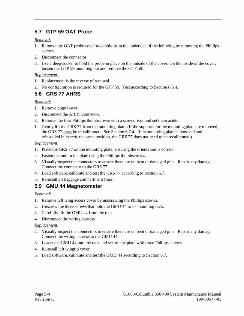
Page 5-4 G1000-Columbia 350/400 System Maintenance Manual Revision C 190-00577-03
5.7 GTP 59 OAT Probe Removal:
1. Remove the OAT probe cover assembly from the underside of the left wing by removing the Phillips screws.
2. Disconnect the connector.
3. Use a deep-socket to hold the probe in place on the outside of the cover. On the inside of the cover, loosen the GTP 59 mounting nut and remove the GTP 59.
Replacement:
1. Replacement is the reverse of removal.
2. No configuration is required for the GTP 59. Test according to Section 6.6.4.
5.8 GRS 77 AHRS Removal:
1. Remove pogo tower.
2. Disconnect the AHRS connector.
3. Remove the four Phillips thumbscrews with a screwdriver and set them aside.
1. Gently lift the GRS 77 from the mounting plate. (If the supports for the mounting plate are removed, the GRS 77 must be re-calibrated. See Section 6.7.4. If the mounting plate is removed and reinstalled in exactly the same position, the GRS 77 does not need to be recalibrated.)
Replacement:
1. Place the GRS 77 on the mounting plate, ensuring the orientation is correct.
2. Fasten the unit to the plate using the Phillips thumbscrews.
3. Visually inspect the connectors to ensure there are no bent or damaged pins. Repair any damage. Connect the connector to the GRS 77 .
4. Load software, calibrate and test the GRS 77 according to Section 6.7.
5. Reinstall aft baggage compartment floor.
5.9 GMU 44 Magnetometer Removal:
1. Remove left wing access cover by unscrewing the Phillips screws.
2. Unscrew the three screws that hold the GMU 44 to its mounting rack.
3. Carefully lift the GMU 44 from the rack.
4. Disconnect the wiring harness.
Replacement:
2. Visually inspect the connectors to ensure there are no bent or damaged pins. Repair any damage. Connect the wiring harness to the GMU 44.
3. Lower the GMU 44 into the rack and secure the plate with three Phillips screws.
4. Reinstall left wingtip cover.
5. Load software, calibrate and test the GMU 44 according to Section 6.7.

G1000-Columbia 350/400 System Maintenance Manual Page 5-5 190-00577-03 Revision C
5.10 GDL 69A Data Link Removal:
1. Remove the PFD as described in Section 5.1.
2. Unlock the GDL 69A handle by unscrewing the Phillips screw.
3. Pull the handle upward to unlock the GDL 69A. Gently remove the GDL 69A from its rack.
Replacement:
1. Visually inspect the connectors to ensure there are no bent or damaged pins. Repair any damage.
2. Gently insert the GDL 69A into the rack. The handle should engage the dogleg track.
3. Press down on the handle to lock the unit into place.
4. Lock the handle to the GDL 69A body using the Phillips screw.
5. Reinstall the PFD as described in Section 5.1.
6. Load software, configure and test the GDL 69A according to Section 6.8.
5.11 GCU 476 Removal:
1. Remove the setscrew securing the keypad with a 3/32nd hex tool and carefully remove keypad.
2. While supporting the keypad disconnect the connector.
3. Remove the unit.
Replacement:
1. Connect the connector to the back of keypad.
2. Gently place keypad into position.
3. Secure with setscrew using a 3/32nd hex tool. Do not over-tighten.
4. Load software, configure and test according to Section 6.11.
5.12 GSA 81 Autopilot Roll Servo Removal:
1. Remove the belly access panel.
2. Disconnect servo connector P680 (1P801).
3. Remove the four screws holding servo to servo mount.
4. Remove unit.
5. Remove excess grease build-up from the single servo output gear using a lint-free cloth.
NOTE
It is not necessary to remove all of the grease from the output gear, only the excess grease. DO NOT USE SOLVENTS TO CLEAN THE OUTPUT GEAR!
6. Using a brush or other applicator, apply a thin coat of grease to the servo output gear. Use Aeroshell 17 or equivalent (Synthetic Diester, Low Temp; Must meet MIL-G-21164D).
Replacement:
1. Set unit in place.
2. Visually inspect the connectors to ensure there are no bent or damaged pins. Repair any damage.
3. Install the four screws holding the servo to the servo mount.
4. Connect servo connector 2P801.
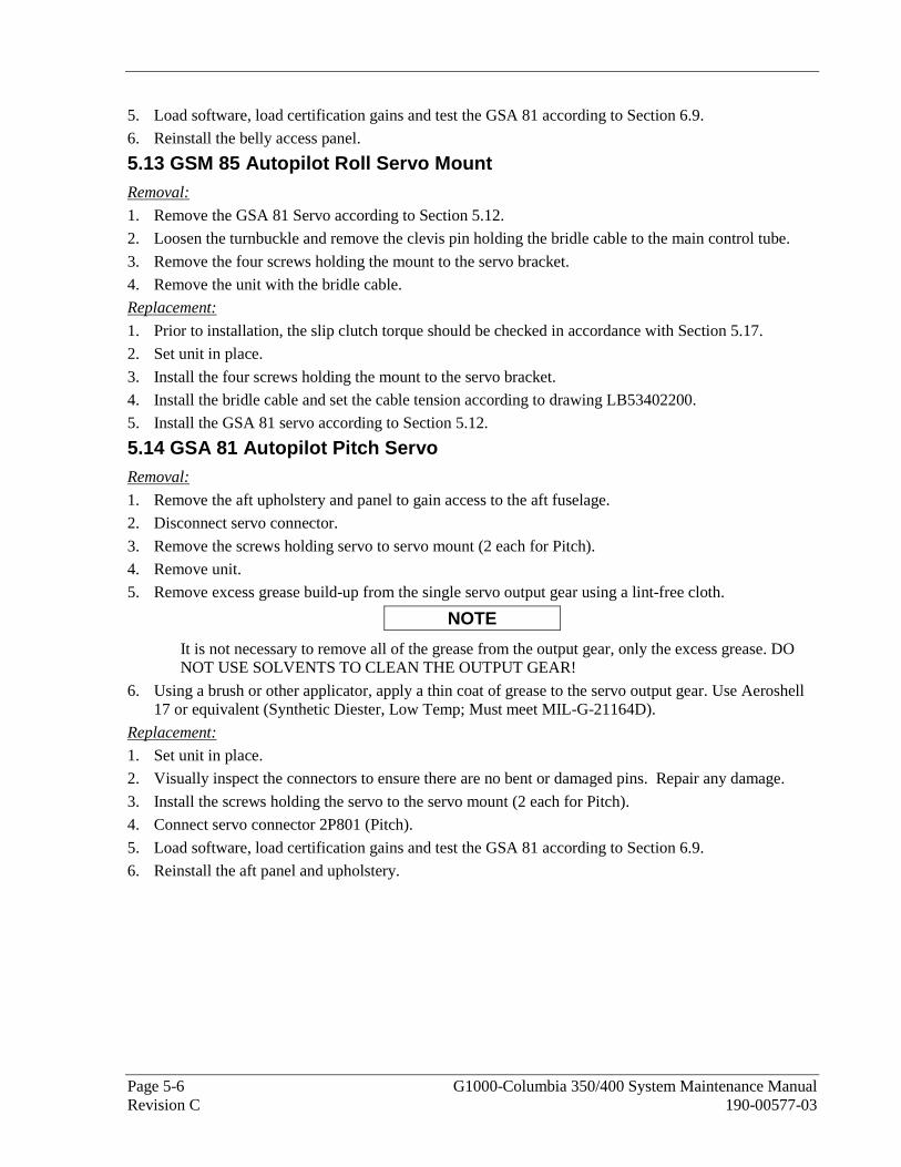
Page 5-6 G1000-Columbia 350/400 System Maintenance Manual Revision C 190-00577-03
5. Load software, load certification gains and test the GSA 81 according to Section 6.9.
6. Reinstall the belly access panel.
5.13 GSM 85 Autopilot Roll Servo Mount Removal:
1. Remove the GSA 81 Servo according to Section 5.12.
2. Loosen the turnbuckle and remove the clevis pin holding the bridle cable to the main control tube.
3. Remove the four screws holding the mount to the servo bracket.
4. Remove the unit with the bridle cable.
Replacement:
1. Prior to installation, the slip clutch torque should be checked in accordance with Section 5.17.
2. Set unit in place.
3. Install the four screws holding the mount to the servo bracket.
4. Install the bridle cable and set the cable tension according to drawing LB53402200.
5. Install the GSA 81 servo according to Section 5.12.
5.14 GSA 81 Autopilot Pitch Servo Removal:
1. Remove the aft upholstery and panel to gain access to the aft fuselage.
2. Disconnect servo connector.
3. Remove the screws holding servo to servo mount (2 each for Pitch).
4. Remove unit.
5. Remove excess grease build-up from the single servo output gear using a lint-free cloth.
NOTE
It is not necessary to remove all of the grease from the output gear, only the excess grease. DO NOT USE SOLVENTS TO CLEAN THE OUTPUT GEAR!
6. Using a brush or other applicator, apply a thin coat of grease to the servo output gear. Use Aeroshell 17 or equivalent (Synthetic Diester, Low Temp; Must meet MIL-G-21164D).
Replacement:
1. Set unit in place.
2. Visually inspect the connectors to ensure there are no bent or damaged pins. Repair any damage.
3. Install the screws holding the servo to the servo mount (2 each for Pitch).
4. Connect servo connector 2P801 (Pitch).
5. Load software, load certification gains and test the GSA 81 according to Section 6.9.
6. Reinstall the aft panel and upholstery.
G1000-Columbia 350/400 System Maintenance Manual Page 5-7 190-00577-03 Revision C
5.15 GSM 85 Autopilot Pitch Servo Mount Removal:
1. Remove the GSA 81 Servo according to Section 5.14.
2. Loosen the turnbuckle and remove the clevis pin holding the bridle cable to the main control tube.
3. Remove the four screws holding the mount to the servo bracket.
4. Remove the unit with the bridle cable.
Replacement:
1. Prior to installation, the slip clutch torque should be checked in accordance with Section 5.17.
2. Set unit in place.
3. Install the four screws holding the mount to the servo bracket.
4. Install the bridle cable and set the cable tension according to drawing LB53402200.
5. Install the GSA 81 servo according to Section 5.14.
5.16 GTA 82 Pitch Trim Removal:
1. Remove four screws securing the GTA 82 adapter to the panel. The GTA 82 adapter is located under the instrument panel on the pilot side beneath the standby instruments.
2. Disconnect servo connector.
3. Remove unit.
Replacement:
1. Set unit in place.
2. Install four screws. Do not over-tighten.
3. Connect servo connector.
4. Load software, load certification gains and test the GTA 82 according to Section 6.9.
5.17 GSM Slip Clutch Adjustment Procedure The slip clutches must adjusted to the limits prescribed on the Autopilot Assembly GIFD drawing, LB53402200. This adjustment requires the use of the Garmin servo adjustment fixture, P/N 011-01085-10 or other approved method. It is recommended that clutches be set in room temperature conditions with low humidity. Temperatures of 15°C to 25°C and less than 50% humidity will yield the best results.
Prior to installing the servo mount, adjust and verify the slip clutch torque is set to the value specified in the GFC 700 Autopilot Installation drawing.
1. Place the servo mount onto the Garmin servo adjustment fixture and secure with toggle clamps.
2. Install the cable supplied with the stand between the capstan under test and the fixture capstan.
3. Remove the slack in the cable with a tension adjust knob.
4. Tighten the thumbscrews on the fixture capstan.
5. Attach a socket to a calibrated torque wrench of the appropriate range and place the assembly on top of the fixture capstan. The torque wrench handle should go through the wrench support so that it contacts the handle in the location appropriate for that particular torque wrench.
6. Connect a 24 VDC power supply to the test stand.
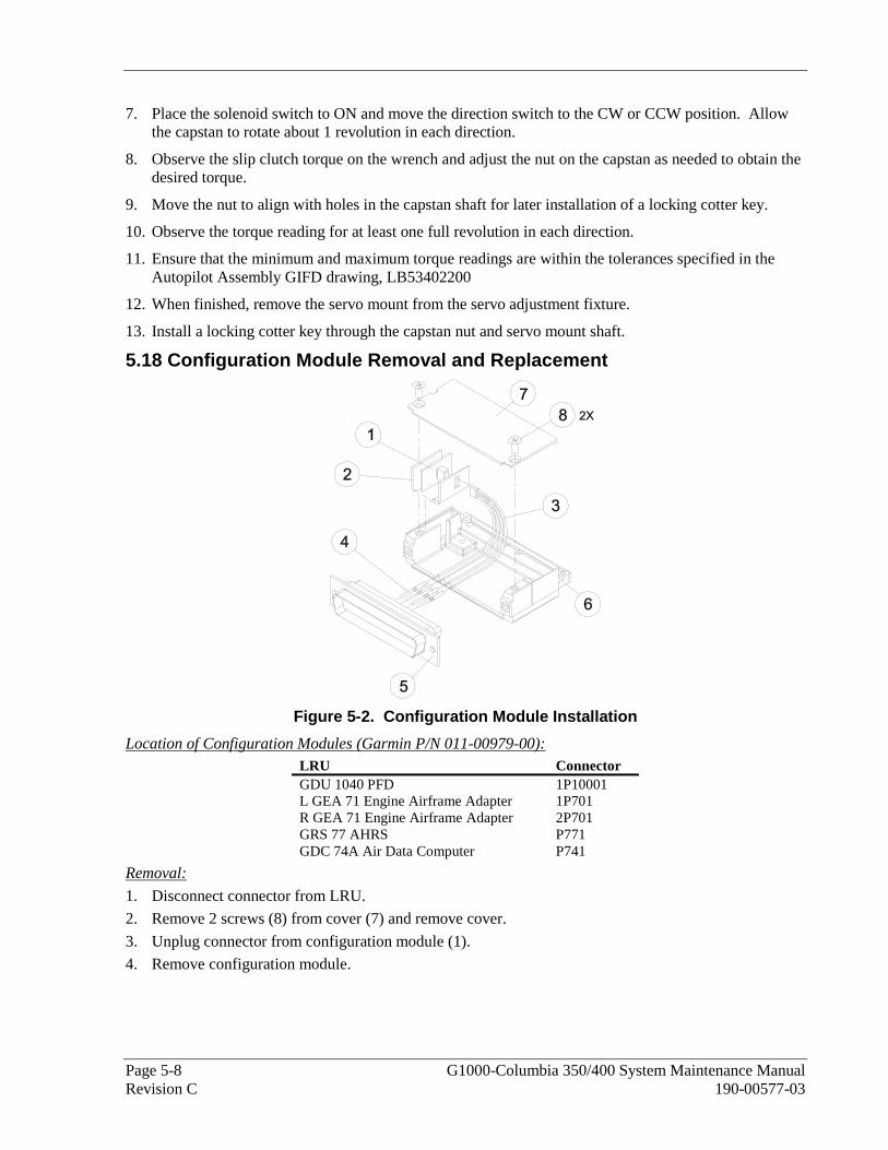
Page 5-8 G1000-Columbia 350/400 System Maintenance Manual Revision C 190-00577-03
7. Place the solenoid switch to ON and move the direction switch to the CW or CCW position. Allow the capstan to rotate about 1 revolution in each direction.
8. Observe the slip clutch torque on the wrench and adjust the nut on the capstan as needed to obtain the desired torque.
9. Move the nut to align with holes in the capstan shaft for later installation of a locking cotter key.
10. Observe the torque reading for at least one full revolution in each direction.
11. Ensure that the minimum and maximum torque readings are within the tolerances specified in the Autopilot Assembly GIFD drawing, LB53402200
12. When finished, remove the servo mount from the servo adjustment fixture.
13. Install a locking cotter key through the capstan nut and servo mount shaft.
5.18 Configuration Module Removal and Replacement
Figure 5-2. Configuration Module Installation
Location of Configuration Modules (Garmin P/N 011-00979-00): LRU Connector GDU 1040 PFD 1P10001 L GEA 71 Engine Airframe Adapter 1P701 R GEA 71 Engine Airframe Adapter 2P701 GRS 77 AHRS P771 GDC 74A Air Data Computer P741
Removal:
1. Disconnect connector from LRU.
2. Remove 2 screws (8) from cover (7) and remove cover.
3. Unplug connector from configuration module (1).
4. Remove configuration module.

G1000-Columbia 350/400 System Maintenance Manual Page 5-9 190-00577-03 Revision C
Replacement:
1. Inspect connector for damaged pins (4).
2. Place configuration module (1) in position.
3. Insert connector into configuration module (1).
4. Assembly of the connector is the reverse of disassembly.
If the GRS 77 AHRS Configuration Module is replaced:
All three GRS 77 /GMU 44 calibration procedures must be performed. Proceed to Section 6.7.4
If GDC 74 Configuration Module is replaced:
Configuration settings must be reloaded to the GDC 74A. Proceed to Section 6.7.4
If GEA 71 Configuration Module is replaced:
No configuration is required.
If the Master Configuration Module is replaced:
NOTE
The G1000 System ID number will change when installing a new master configuration module. New SD database cards, as well as the optional features unlock cards (i.e. TAWS unlock cards, ChartView unlock card), will need to be replaced when the master configuration module is changed. The old data cards will no longer function as they remain locked to the old System ID number.
1. Start the G1000 system in configuration mode as described in Section 3.4.
2. Go to the Configuration Upload Page on the PFD.
3. Press the UPDT CFG softkey.
4. Replace Terrain/Obstacle cards as they will be locked to the old System ID number in the original configuration module.
5. Unlock optional features as appropriate (i.e. TAWS and ChartView). See Section 6.12.
If both the PFD and Master Configuration Module is replaced:
The G1000 system (except GRS 77 /GMU 44 and GDC 74A) must be re-configured. Proceed to Section 6.
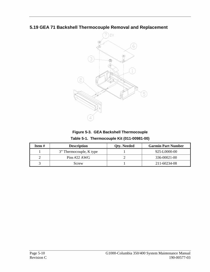
Page 5-10 G1000-Columbia 350/400 System Maintenance Manual Revision C 190-00577-03
5.19 GEA 71 Backshell Thermocouple Removal and Replacement
Figure 5-3. GEA Backshell Thermocouple
Table 5-1. Thermocouple Kit (011-00981-00)
Item # Description Qty. Needed Garmin Part Number
1 3” Thermocouple, K type 1 925-L0000-00
2 Pins #22 AWG 2 336-00021-00
3 Screw 1 211-60234-08

G1000-Columbia 350/400 System Maintenance Manual Page 5-11 190-00577-03 Revision C
Removal:
1. Remove GEA 71 per Section 5.4.
2. Remove GEA connector backplate.
3. Remove connector J701 (5) from the backplate.
4. Remove cover (6) from the backshell.
5. Unscrew thermocouple from boss on backshell. Extract the thermocouple pins from the connector.
Replacement:
1. Crimp pins (2) onto each of the thermocouple wires (1). Ensure that pre-stripped wire length is 1/8” prior to crimping.
2. Insert newly crimped pins and wires into the appropriate connector housing location (4) as specified by the 350/400 avionics wiring diagram.
3. Place thermocouple body (1) onto the backshell boss (5). Place the thermocouple as shown in Figure 5-3 so that the wires exit towards the bottom of the backshell.
4. Fasten thermocouple tightly to backshell using the provided screw (3).
5. Fasten cover (6) to backshell using the provided screws (7).
NOTE
If the GEA thermocouple is replaced, no reconfiguration is required.

Page 5-12 G1000-Columbia 350/400 System Maintenance Manual Revision C 190-00577-03
This Page Intentionally Left Blank

G1000-Columbia 350/400 System Maintenance Manual Page 6-1 190-00577-03 Revision C
6 G1000 EQUIPMENT CONFIGURATION AND TESTING This section provides procedures to be followed after a piece of G1000 equipment is replaced. At the beginning of each LRU section, instructions are given to guide the technician for various removal/replacement scenarios. These instructions define necessary procedures to be followed for situations in which original equipment was reinstalled as well as for situations in which new equipment (new serial number) is installed.
CAUTION
Remove Supplemental Database Cards from the lower slot of all displays before loading software into any unit. Not removing the cards may corrupt them. Replacing corrupted database cards are not covered under warranty.
Garmin recommends the use of Sandisk or Toshiba SD cards for loading software and configuration files. Use of other brand cards is not recommended.
WARNING
Connect a ground power unit to the aircraft for software loading. Do not rely on only the aircraft batteries to prevent loss of power during the software loading process. DO NOT ALLOW POWER TO BE REMOVED FROM THE SYSTEM WHEN LOADING SOFTWARE! Remove power only when told to do so by the following procedure. As a general rule all displays should be in the same mode (configuration or normal), unless instructed differently.
6.1 GDU 1040 PFD/GDU 1042 MFD Original Display Reinstalled
If the removed display(s) are re-installed in their original positions, no software or configuration loading is required. This does not include units that were returned for repair as their software and configuration files are deleted during the repair testing process. Continue to the PFD/MFD Test procedure.
PFD and MFD Displays Installed in Opposite Locations for Troubleshooting
If PFD and MFD are installed in opposite locations for troubleshooting, no software or configuration loading is required. When troubleshooting is complete, displays must be returned to their original positions. Continue to PFD/MFD Test procedure.
New or Repaired Display(s) Installed
If a new GDU 1040 or GDU 1042 is installed, the correct software and configuration files must be loaded to the unit.
6.1.1 PFD/MFD Software Loading using GDU V6.XX
NOTE
The procedure in this section applies only to aircraft with GDU software version 6.XX. Procedures for G1000 systems with GDU version 8.XX follow this section.
1. Pull the MFD or PFD circuit breaker corresponding to the display being replaced.
2. Remove the Supplemental Database cards from the bottom slots of each display. Note which card was removed from the MFD so it may be identified later for reinsertion in the MFD when software and configuration loading is complete. It contains a FliteChart or ChartView database which is only used by the MFD.

Page 6-2 G1000-Columbia 350/400 System Maintenance Manual Revision C 190-00577-03
3. Insert the appropriate G1000-Columbia 350/400 Code Loader Card into the replaced display top card slot. See the Required Equipment List for correct Loader Card part number.
4. Hold the ENT and CLR keys on the replaced display and restore power by closing the applicable circuit breaker (power only the replaced unit).
5. When the words appear in the upper left corner of the display, release the ENT and CLR keys.
6. Press the ENT key to acknowledge the following prompt:
7. Press the ENT key to acknowledge the following prompt:
8. The following screen is displayed.
9. Software is loaded to the replaced display. When complete, the display starts in configuration mode.
10. If both displays were replaced, repeat steps 1-8 for the opposite display.
11. Continue to the PFD/MFD Configuration procedure.
6.1.2 PFD/MFD Configuration using GDU V6.XX
NOTE
The procedure in this section applies only to aircraft with GDU software version 6.XX. Procedures for G1000 systems with GDU version 8.XX follow this section
1. Insert the correct G1000-Columbia 350/400 Code Loader Card (see Required Equipment List) into the PFD top card slot, if it is not already in the PFD.
2. Start both the MFD and PFD in Configuration mode by holding the ENT key during power up until INITIALIZING SYSTEM appears in the upper left corner of the display.
3. On the PFD, go to the Configuration Upload page using the small FMS knob:
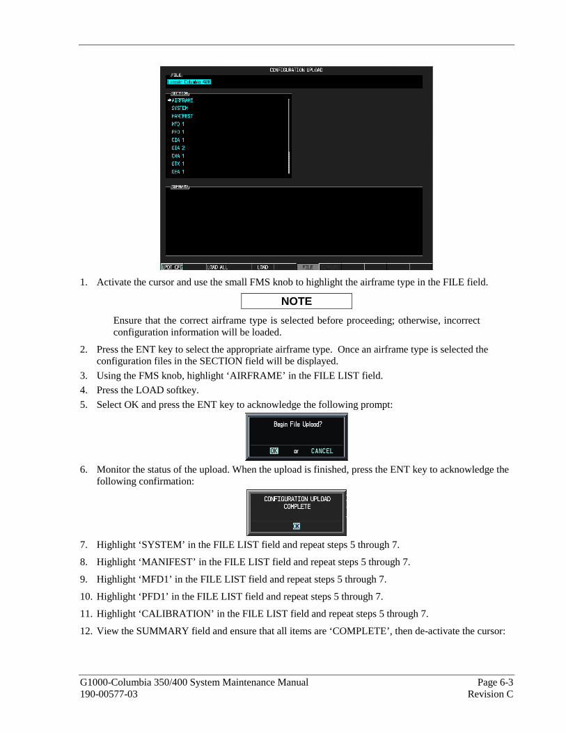
G1000-Columbia 350/400 System Maintenance Manual Page 6-3 190-00577-03 Revision C
1. Activate the cursor and use the small FMS knob to highlight the airframe type in the FILE field.
NOTE
Ensure that the correct airframe type is selected before proceeding; otherwise, incorrect configuration information will be loaded.
2. Press the ENT key to select the appropriate airframe type. Once an airframe type is selected the configuration files in the SECTION field will be displayed.
3. Using the FMS knob, highlight ‘AIRFRAME’ in the FILE LIST field.
4. Press the LOAD softkey.
5. Select OK and press the ENT key to acknowledge the following prompt:
6. Monitor the status of the upload. When the upload is finished, press the ENT key to acknowledge the
following confirmation:
7. Highlight ‘SYSTEM’ in the FILE LIST field and repeat steps 5 through 7.
8. Highlight ‘MANIFEST’ in the FILE LIST field and repeat steps 5 through 7.
9. Highlight ‘MFD1’ in the FILE LIST field and repeat steps 5 through 7.
10. Highlight ‘PFD1’ in the FILE LIST field and repeat steps 5 through 7.
11. Highlight ‘CALIBRATION’ in the FILE LIST field and repeat steps 5 through 7.
12. View the SUMMARY field and ensure that all items are ‘COMPLETE’, then de-activate the cursor:

Page 6-4 G1000-Columbia 350/400 System Maintenance Manual Revision C 190-00577-03
13. At the System Status page, activate the cursor and highlight ‘PFD1’ and ‘MFD1’ in the LRU window.
14. Verify that the part number and version of the software reported matches the data in the Required Equipment List.
15. Continue to the Aviation Database Loading procedure.
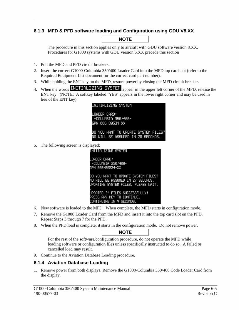
G1000-Columbia 350/400 System Maintenance Manual Page 6-5 190-00577-03 Revision C
6.1.3 MFD & PFD software loading and Configuration using GDU V8.XX
NOTE
The procedure in this section applies only to aircraft with GDU software version 8.XX. Procedures for G1000 systems with GDU version 6.XX precede this section
1. Pull the MFD and PFD circuit breakers.
2. Insert the correct G1000-Columbia 350/400 Loader Card into the MFD top card slot (refer to the Required Equipment List document for the correct card part number).
3. While holding the ENT key on the MFD, restore power by closing the MFD circuit breaker.
4. When the words appear in the upper left corner of the MFD, release the ENT key. (NOTE: A softkey labeled ‘YES’ appears in the lower right corner and may be used in lieu of the ENT key):
5. The following screen is displayed:
6. New software is loaded to the MFD. When complete, the MFD starts in configuration mode.
7. Remove the G1000 Loader Card from the MFD and insert it into the top card slot on the PFD. Repeat Steps 3 through 7 for the PFD.
8. When the PFD load is complete, it starts in the configuration mode. Do not remove power.
NOTE For the rest of the software/configuration procedure, do not operate the MFD while loading software or configuration files unless specifically instructed to do so. A failed or cancelled load may result.
9. Continue to the Aviation Database Loading procedure.
6.1.4 Aviation Database Loading
1. Remove power from both displays. Remove the G1000-Columbia 350/400 Code Loader Card from the display.

Page 6-6 G1000-Columbia 350/400 System Maintenance Manual Revision C 190-00577-03
2. Remove the Supplemental Database cards from the bottom slots of each display. Note which card was removed from the MFD so it may be identified later for reinsertion in the MFD when software and configuration loading is complete. It contains a FliteChart or ChartView database which is only used by the MFD.
3. Insert an aviation database update SD card into the top slot of the PFD.
4. Apply power to the PFD. The following prompt is displayed in the upper left corner of the PFD:
5. Press the ENT key to confirm the database update. The following prompt is displayed:
6. After the update completes, the PFD starts in normal mode. Remove the aviation database update SD Card from the PFD.
7. Remove power from the MFD.
8. Repeat steps 3 through 5 for the MFD. The MFD and PFD aviation databases are now updated.
9. Confirm that the correct update cycle and version is loaded during startup of the MFD.
10. Remove the aviation database update SD Card from the MFD.
11. After the software and configuration files are loaded, turn off the system and reinsert the Supplemental Database Cards in the bottom slot of each display. Be sure to insert the card removed from the MFD back into the MFD.
12. Continue to the PFD/MFD Test procedure.
6.1.5 PFD/MFD Test
1. Allow displays to initialize for ~1 minute.
2. Check that all COM/NAV display fields are valid in the top corners of the display.
For PFD: Check that attitude, heading, altitude, airspeed, vertical speed and OAT fields are valid within 2 minutes of power up.
For MFD: Check that the engine instrument fields are valid.
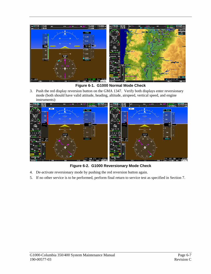
G1000-Columbia 350/400 System Maintenance Manual Page 6-7 190-00577-03 Revision C
Figure 6-1. G1000 Normal Mode Check
3. Push the red display reversion button on the GMA 1347. Verify both displays enter reversionary mode (both should have valid attitude, heading, altitude, airspeed, vertical speed, and engine instruments):
Figure 6-2. G1000 Reversionary Mode Check
4. De-activate reversionary mode by pushing the red reversion button again.
5. If no other service is to be performed, perform final return to service test as specified in Section 7.

Page 6-8 G1000-Columbia 350/400 System Maintenance Manual Revision C 190-00577-03
6.2 GMA 1347 Audio Panel Original GMA 1347 Reinstalled
No software/configuration loading or testing is required if the removed GMA 1347 is re-installed. This does not include units that were returned for repair as their software and configuration files are deleted during the repair testing process. Continue to the final return-to-service checks in Section 7.
New or Repaired GMA 1347 Installed
If a new GMA 1347 is installed, the correct software and configuration files must be loaded to the unit.
6.2.1 GMA 1347 Software Loading using GDU V6.XX
NOTE
The procedure in this section applies only to aircraft with GDU software version 6.XX. Procedures for G1000 systems with GDU version 8.XX follow this section
1. Remove the Supplemental Database cards from the bottom slots of each display. Note which card was removed from the MFD so it may be identified later for reinsertion in the MFD when software and configuration loading is complete. It contains a FliteChart or ChartView database which is only used by the MFD.
2. Insert the correct G1000-Columbia 350/400 Code Loader Card (see Required Equipment List) into the top slot of the PFD.
3. Start the G1000 system in Configuration mode.
4. On the PFD, go to the Software Upload page using the small FMS knob.
5. Highlight the GMA software file. Ensure that both paths to the GMA through GIA1 and GIA 2 appear in the LRU field as shown:
6. Press the LRU softkey. Select the GMA1 - GIA1 data path to load software. Press the LOAD softkey.
7. Select OK and press the ENT key to acknowledge the following prompt:
8. The software for the GMA 1347 Audio Panel begins to load. Monitor the upload status as it progresses:
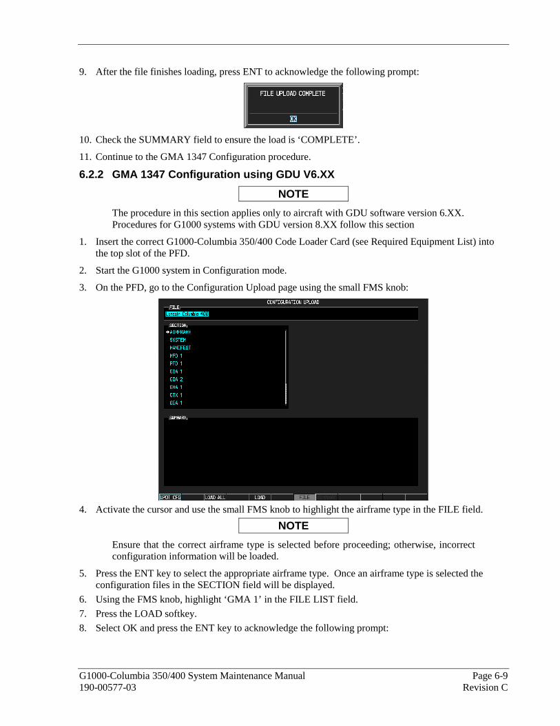
G1000-Columbia 350/400 System Maintenance Manual Page 6-9 190-00577-03 Revision C
9. After the file finishes loading, press ENT to acknowledge the following prompt:
10. Check the SUMMARY field to ensure the load is ‘COMPLETE’.
11. Continue to the GMA 1347 Configuration procedure.
6.2.2 GMA 1347 Configuration using GDU V6.XX
NOTE
The procedure in this section applies only to aircraft with GDU software version 6.XX. Procedures for G1000 systems with GDU version 8.XX follow this section
1. Insert the correct G1000-Columbia 350/400 Code Loader Card (see Required Equipment List) into the top slot of the PFD.
2. Start the G1000 system in Configuration mode.
3. On the PFD, go to the Configuration Upload page using the small FMS knob:
4. Activate the cursor and use the small FMS knob to highlight the airframe type in the FILE field.
NOTE
Ensure that the correct airframe type is selected before proceeding; otherwise, incorrect configuration information will be loaded.
5. Press the ENT key to select the appropriate airframe type. Once an airframe type is selected the configuration files in the SECTION field will be displayed.
6. Using the FMS knob, highlight ‘GMA 1’ in the FILE LIST field.
7. Press the LOAD softkey.
8. Select OK and press the ENT key to acknowledge the following prompt:

Page 6-10 G1000-Columbia 350/400 System Maintenance Manual Revision C 190-00577-03
9. Monitor the status of the upload. When the upload is finished, press the ENT key to acknowledge the
following confirmation:
10. View the SUMMARY field and ensure that the load is ‘COMPLETE’, then de-activate the cursor.
11. Go to the System Status page.
12. Activate the cursor and highlight ‘GMA1 – GIA1’ in the LRU window.
13. Verify that the reported part number and version of the software file matches the data in Required Equipment List.
14. After the software and configuration files are loaded, turn off the system and reinsert the Supplemental Database Cards in the bottom slot of each display. Be sure to insert the card removed from the MFD back into the MFD.
15. Continue to the GMA 1347 Test procedure.
6.2.3 GMA 1347 Software Load and Configuration using GDU V8.XX
NOTE
The procedure in this section applies only to aircraft with GDU software version 8.XX. Procedures for G1000 systems with GDU version 6.XX precede this section
1. On the PFD, go to the System Upload page using the small FMS knob.
2. Activate the cursor and use the small FMS knob to highlight the airframe type in the AIRFRAME field. Select the appropriate aircraft type (C400 or C350) and press the ENT key.
NOTE
Ensure that the correct airframe type is selected before proceeding; otherwise, incorrect configuration information will be loaded.
3. Once an airframe type is selected the cursor moves to the FILE window. Rotate the small FMS knob to activate the drop-down menu. Three FQIS fuel tank options are available: 49 gallon (non-adjusted); 49 gallon (adjusted); 51 gallon. Confirm the serial number of the aircraft prior to selection as well as inspect logbooks for field upgrades according to the following table.

G1000-Columbia 350/400 System Maintenance Manual Page 6-11 190-00577-03 Revision C
C350 C400 Comments
49 Gallon (non-adjusted) 42502 - 42564 41563 - 41757 Verify logbooks for compliance with Columbia Service Letter SL-07-008B
49 Gallon (adjusted) 42565 - 42567 41758 - 41799
51 Gallon 42568 and higher 41800 and higher Inspect fuel tank placard
If the aircraft is a Columbia 350 within the serial number range of 42502-42564 or a Columbia 400 within the serial number range of 41563-41757, confirm the FQIS fuel tank option by referencing the aircrafts logbooks. Compliance with Columbia Service Letter number SL-07-008B requires the selection of “49 gallon adjusted”. Columbia aircraft with 51 gallon tanks can be verified by inspection of the fuel tank placard.
NOTE
At this step, select to load WAAS or non-WAAS G1000 software.
4. The PRODUCT window will populate and display software and configuration file information for
each G1000 LRU. The LRU VERS column shows the currently loaded software version in the LRU, whereas the CARD VERS column shows the LRU software version stored on the Loader Card. Each check designates a file to be loaded to the G1000.
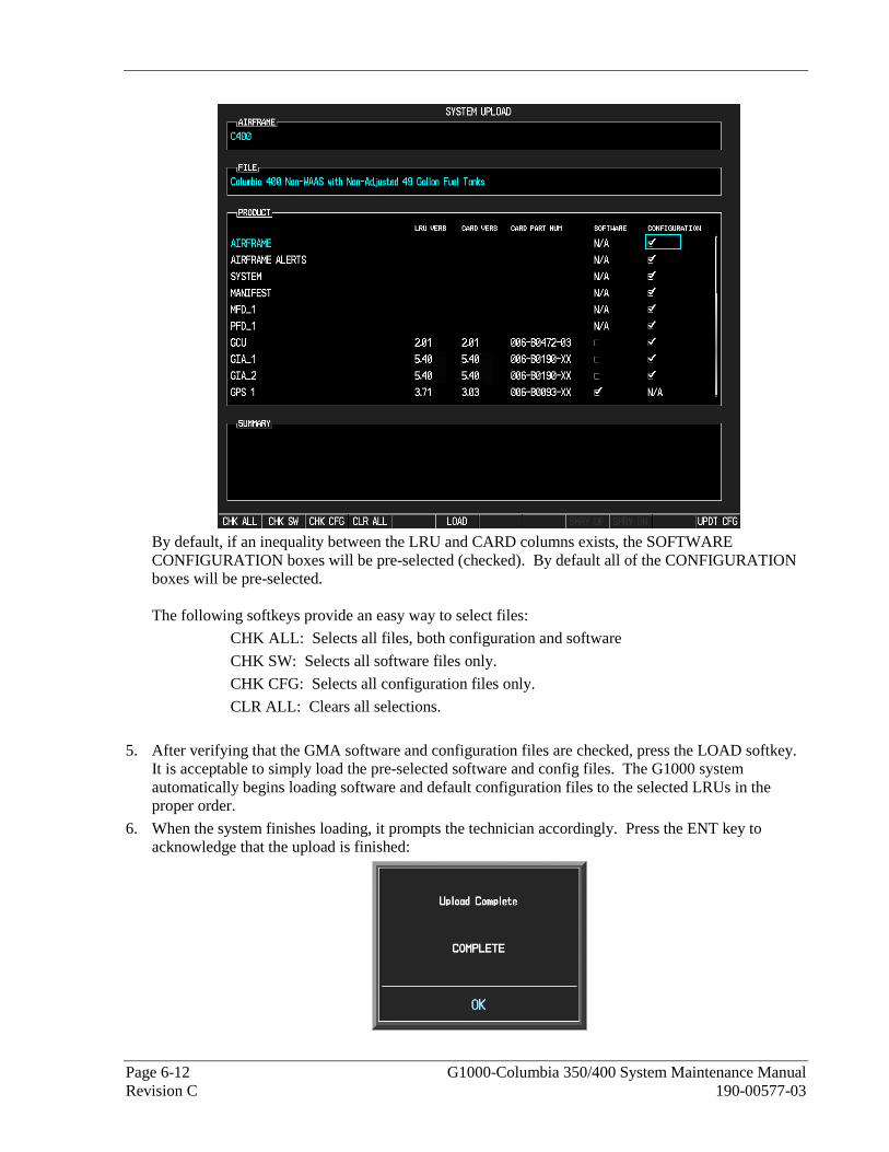
Page 6-12 G1000-Columbia 350/400 System Maintenance Manual Revision C 190-00577-03
By default, if an inequality between the LRU and CARD columns exists, the SOFTWARE CONFIGURATION boxes will be pre-selected (checked). By default all of the CONFIGURATION boxes will be pre-selected. The following softkeys provide an easy way to select files:
CHK ALL: Selects all files, both configuration and software
CHK SW: Selects all software files only.
CHK CFG: Selects all configuration files only.
CLR ALL: Clears all selections.
5. After verifying that the GMA software and configuration files are checked, press the LOAD softkey. It is acceptable to simply load the pre-selected software and config files. The G1000 system automatically begins loading software and default configuration files to the selected LRUs in the proper order.
6. When the system finishes loading, it prompts the technician accordingly. Press the ENT key to acknowledge that the upload is finished:
G1000-Columbia 350/400 System Maintenance Manual Page 6-13 190-00577-03 Revision C
7. Verify that each column indicates in green when the loading process has finished and inspect the SUMMARY window as well to ensure that the load is successful.
8. After the software and configuration files are loaded, turn off the system and reinsert the Supplemental Database Cards in the bottom slot of each display. Be sure to insert the card removed from the MFD back into the MFD.
9. Continue to the GMA 1347 Test procedure.

Page 6-14 G1000-Columbia 350/400 System Maintenance Manual Revision C 190-00577-03
6.2.4 GMA 1347 Test
Except for marker beacon operation, an in-aircraft checkout may be performed in the aircraft with known good microphone, headset, and speaker.
Intercom System (ICS) Check:
1. Plug in headsets at each ICS position.
2. Ensure that the MAN SQ key is off (no light).
3. Adjust volume for each position and verify that the ICS is working properly.
4. Check Pilot and Copilot ICS positions for isolation and proper operation of volume and squelch controls.
5. Press the PA key. Verify that microphone audio is heard over the speaker when the Push-To-Talk (PTT) key is pressed.
Transceiver Operational Check:
Perform a ramp test radio check by exercising the installed transceivers, microphone, microphone key and audio over the headphones and speaker. Verify that communications are clear and PTT operation is correct for each pilot position.
1. Select the audio source corresponding to each installed avionics unit (i.e. NAV1, NAV2, COM1, COM2) and check for audio over the headsets.
2. Press the SPKR key and verify that the selected audio is heard over the speaker.
Failsafe Operation Check:
1. Turn the GMA 1347 off by pulling the AUDIO MKR circuit breaker. This directs all COM 1 phone audio, MIC audio and MIC key to the pilot’s position.
2. Check the failsafe operation by exercising the COM 1 microphone, microphone key and audio over the headphones. All volume control for the COM audio should be through the PFD/MFD volume control. Verify proper operation of COM 1 using the failsafe operation.
3. Close the AUDIO MKR circuit breaker to continue testing.
Marker Beacon Test:
Figure 6-3. Marker Beacon Symbology
Using a ramp tester, simulate the outer marker, middle marker and inner marker signals by following the test equipment manufacturer’s instructions. Verify that each marker audio signal is present over the headphones and speaker.
Verify that the outer, middle, and inner annunciations appear on the PFD when the corresponding signal is applied. Marker beacon annunciations appear at the upper left corner of the altitude indicator on the PFD. Operate the MKR MUTE key on the GMA 1347 and ensure that the audio signal is muted.
If no other service is to be performed, continue to the return-to-service checks in Section 7.

G1000-Columbia 350/400 System Maintenance Manual Page 6-15 190-00577-03 Revision C
6.3 GIA 63 Integrated Avionics Unit Original GIA 63(s) Reinstalled:
No software or configuration loading is required if the removed GIA is re-installed in its original position (GIA1 and GIA2 in their original racks). This does not include units that were returned for repair as their software and configuration files are deleted during the repair testing process. Continue to the return-to-service checks in Section 7.
Original GIA 63s Installed in Opposite Locations for Troubleshooting:
No software loading is required if the originally installed GIA units are re-installed in opposite positions (GIA1 and GIA2 in opposite unit racks). However, the units must be re-configured. Continue to the GIA 63 Configuration Loading procedure.
New or Repaired GIA 63(s) Installed
If a new GIA 63 is installed, the correct software, configuration files, and certification gains must be loaded to the unit. Continue to the GIA 63 Software Loading procedure.
6.3.1 GIA 63 Software Loading using GDU V6.XX
NOTE
The procedure in this section applies only to aircraft with GDU software version 6.XX. Procedures for G1000 systems with GDU version 8.XX follow this section.
1. Remove the Supplemental Database cards from the bottom slots of each display. Note which card was removed from the MFD so it may be identified later for reinsertion in the MFD when software and configuration loading is complete. It contains a FliteChart or ChartView database which is only used by the MFD.
2. Insert the correct G1000-Columbia 350/400 Code Loader Card (see Required Equipment List) into top slot of PFD.
3. Start the G1000 system in Configuration mode.
4. On the PFD, go to the Software Upload page using the small FMS knob.
5. Activate the cursor and select the GIA software file. Verify that GIA1 and GIA2 appear in the LRU field as shown:
6. Press the LRU softkey and select the appropriate replaced GIA. Press the LOAD softkey.
7. Select OK and press ENT to acknowledge the following prompt:

Page 6-16 G1000-Columbia 350/400 System Maintenance Manual Revision C 190-00577-03
8. The software for GIA1 begins to load. GIA2 software loads immediately after GIA1 software finishes loading. Monitor the upload status as it progresses:
9. 9. After the files finish loading, press ENT to acknowledge the following prompt:
10. View the SUMMARY field and verify that both GIA1 and GIA2 software loading is complete.
11. Highlight the GPS software file. Ensure that GPS1 and GPS2 appear in the LRU field as shown:
12. Press the LOAD softkey.
13. Select OK and press the ENT key to acknowledge the following prompt:
14. The software for GPS1 begins to load. GPS2 software loads immediately after GPS1 software
finishes loading. Monitor the upload status as it progresses:
15. After the files finish loading, press ENT to acknowledge the following prompt:
16. Activate the cursor and select the GIA Audio software file. Ensure that GIA1 and GIA2 appear in the
LRU field as shown:

G1000-Columbia 350/400 System Maintenance Manual Page 6-17 190-00577-03 Revision C
NOTE
The version that appears in the LRU window on the right is the current version of GIA system software. The version that appears in the GIA AUDIO file description on the left is the GIA audio software version. The two versions will not necessarily match.
17. Press the LOAD softkey.
18. Select OK and press the ENT key to acknowledge the following prompt:
19. The software for GIA1 Audio begins to load. GIA2 Audio software loads immediately after GIA1
Audio software finishes loading. Monitor the upload status as it progresses:
20. After the files finish loading, press ENT to acknowledge the following prompt:
21. Check the SUMMARY field to ensure the load is ‘COMPLETE’.
22. Go to the System Status page.
23. Activate the cursor and highlight each of the following items in the LRU window:
-GIA1 -GIA1 Audio -GIA2 -GIA2 Audio -GPS1 -GPS2
24. Check the reported part number/version of each software file and compare to the data in the Required Equipment List.
25. Check the SUMMARY field to ensure the load is ‘COMPLETE’.
26. De-activate the cursor.
27. Continue to the GIA 63 Configuration Loading procedure.
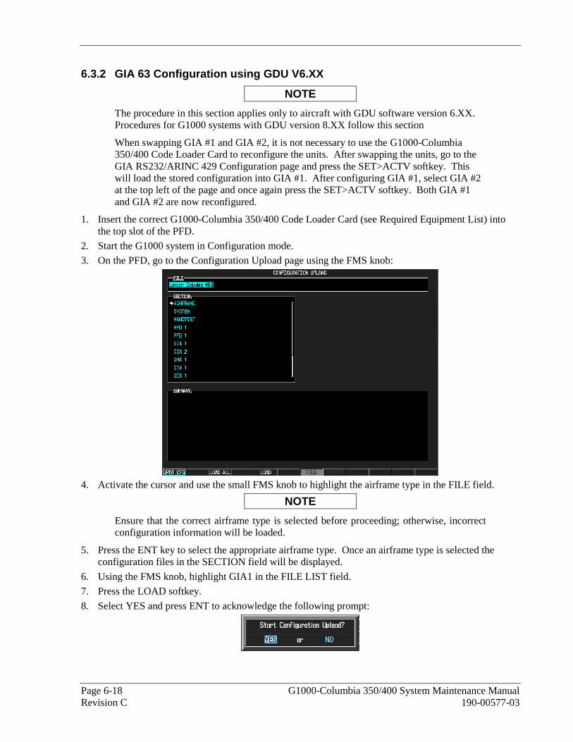
Page 6-18 G1000-Columbia 350/400 System Maintenance Manual Revision C 190-00577-03
6.3.2 GIA 63 Configuration using GDU V6.XX
NOTE
The procedure in this section applies only to aircraft with GDU software version 6.XX. Procedures for G1000 systems with GDU version 8.XX follow this section
When swapping GIA #1 and GIA #2, it is not necessary to use the G1000-Columbia 350/400 Code Loader Card to reconfigure the units. After swapping the units, go to the GIA RS232/ARINC 429 Configuration page and press the SET>ACTV softkey. This will load the stored configuration into GIA #1. After configuring GIA #1, select GIA #2 at the top left of the page and once again press the SET>ACTV softkey. Both GIA #1 and GIA #2 are now reconfigured.
1. Insert the correct G1000-Columbia 350/400 Code Loader Card (see Required Equipment List) into the top slot of the PFD.
2. Start the G1000 system in Configuration mode.
3. On the PFD, go to the Configuration Upload page using the FMS knob:
4. Activate the cursor and use the small FMS knob to highlight the airframe type in the FILE field.
NOTE
Ensure that the correct airframe type is selected before proceeding; otherwise, incorrect configuration information will be loaded.
5. Press the ENT key to select the appropriate airframe type. Once an airframe type is selected the configuration files in the SECTION field will be displayed.
6. Using the FMS knob, highlight GIA1 in the FILE LIST field.
7. Press the LOAD softkey.
8. Select YES and press ENT to acknowledge the following prompt:

G1000-Columbia 350/400 System Maintenance Manual Page 6-19 190-00577-03 Revision C
9. Monitor the status of the upload. When the upload is finished, press the ENT key to acknowledge the following confirmation:
10. Highlight GIA2 in the FILE LIST field and repeat Steps 3 through 5.
11. Highlight AUDIO in the FILE LIST field and repeat Steps 3 through 5.
12. View the SUMMARY field and ensure that all items are ‘COMPLETE’:
13. De-activate the cursor.
NOTE
After loading the GIA2 configuration, the configuration for the WX-500, Ryan TCAD and Oxygen options will have to be loaded (if installed) according to Section 6.12.
14. Continue to the GIA Certification Gain Loading procedure.
6.3.3 GIA 63 Certification Gain Loading
1. Load certification gains into GIA1 and GIA2 according to Section 6.9.3.
2. After the software and configuration files are loaded, turn off the system and reinsert the Supplemental Database Cards in the bottom slot of each display. Be sure to insert the card removed from the MFD back into the MFD.
3. Continue to the GIA Test procedure.

Page 6-20 G1000-Columbia 350/400 System Maintenance Manual Revision C 190-00577-03
6.3.4 GIA 63 Software Load and Configuration using GDU V8.XX
NOTE
The procedure in this section applies only to aircraft with GDU software version 8.XX. Procedures for G1000 systems with GDU version 6.XX precede this section
1. On the PFD, go to the System Upload page using the small FMS knob.
2. Activate the cursor and use the small FMS knob to highlight the airframe type in the AIRFRAME field. Select the appropriate aircraft type (C400 or C350) and press the ENT key.
NOTE
Ensure that the correct airframe type is selected before proceeding; otherwise, incorrect configuration information will be loaded.
3. Once an airframe type is selected the cursor moves to the FILE window. Rotate the small FMS knob to activate the drop-down menu. Three FQIS fuel tank options are available: 49 gallon (non-adjusted); 49 gallon (adjusted); 51 gallon. Confirm the serial number of the aircraft prior to selection as well as inspect logbooks for field upgrades according to the following table.
C350 C400 Comments
49 Gallon (non-adjusted)
42502 - 42564 41563 - 41757 Verify logbooks for compliance with Columbia Service Letter SL-07-008B
49 Gallon (adjusted)
42565 - 42567 41758 - 41799
51 Gallon 42568 and higher 41800 and higher Inspect fuel tank placard
If the aircraft is a Columbia 350 within the serial number range of 42502-42564 or a Columbia 400 within the serial number range of 41563-41757, confirm the FQIS fuel tank option by referencing the aircrafts logbooks. Compliance with Columbia Service Letter number SL-07-008B requires the selection of “49 gallon adjusted”. Columbia aircraft with 51 gallon tanks can be verified by inspection of the fuel tank placard.

G1000-Columbia 350/400 System Maintenance Manual Page 6-21 190-00577-03 Revision C
NOTE
At this step, select to load WAAS or non-WAAS G1000 software.
4. The PRODUCT window will populate and display software and configuration file information for each G1000 LRU. The LRU VERS column shows the currently loaded software version in the LRU, whereas the CARD VERS column shows the LRU software version stored on the Loader Card. Each check designates a file to be loaded to the G1000.
By default, if an inequality between the LRU and CARD columns exists, the SOFTWARE and CONFIGURATION boxes will be pre-selected (checked).

Page 6-22 G1000-Columbia 350/400 System Maintenance Manual Revision C 190-00577-03
The following softkeys provide an easy way to select files:
CHK ALL: Selects all files, both configuration and software
CHK SW: Selects all software files only.
CHK CFG: Selects all configuration files only.
CLR ALL: Clears all selections.
5. After verifying that the GIA1, GIA2, AUDIO, GPS1, GPS2 and Certification Gains are checked, press the LOAD softkey. It is acceptable to simply load the pre-selected software and config files. The G1000 system automatically begins loading software and default configuration files to the selected LRUs in the proper order.
6. When the system finishes loading, it prompts the technician accordingly. Press the ENT key to acknowledge that the upload is finished:
7. Verify that each column indicates in green when the loading process has finished and inspect the SUMMARY window as well to ensure that the load is successful.
8. After the software and configuration files are loaded, turn off the system and reinsert the Supplemental Database Cards in the bottom slot of each display. Be sure to insert the card removed from the MFD back into the MFD

G1000-Columbia 350/400 System Maintenance Manual Page 6-23 190-00577-03 Revision C
6.3.5 GIA 63 Test
GPS Signal Acquisition:
Figure 6-4. GPS Signal Status
The GIA 63 units should normally acquire a 3D GPS navigation solution within 2 minutes of startup, provided the aircraft is outside (or indoors with a GPS repeater). Select the AUX-GPS STATUS page on the MFD (3rd page in AUX group). Two softkeys on the bottom of the display allow the user to toggle between GPS 1 and GPS 2. Verify that both receivers show 3D Navigation on the MFD.
Continue to the VHF COM Interference test.
VHF COM Interference Test:
This test must be conducted outside. Use of a GPS repeater inside a hangar may result in a failed test. This procedure assumes that the system is currently set to 25 kHz COM channel spacing. Once the signal acquisition test has been completed successfully, perform the following steps:
1. On the MFD, monitor GPS signal strength bars on the 3rd AUX page.
2. On the PFD, ensure that the CDI is set to GPS. If it is not, press the ‘CDI’ softkey until GPS ENR is displayed.
3. Verify that the GPS “INTEG” flag is out of view.
4. Select 121.150 MHz on the No. 1 COM transceiver.
5. Transmit for a period of 35 seconds while monitoring GPS 1 signal strength levels.
6. During the transmit period, verify that the GPS “INTEG” flag does not come into view on the PFD and verify that GPS 1 does not lose a 3-D navigation solution on the MFD.
7. Repeat steps 5 and 6 and re-transmit while monitoring GPS 2 signal levels on the MFD.
8. Repeat steps 5 through 7 for each of the following frequencies:

Page 6-24 G1000-Columbia 350/400 System Maintenance Manual Revision C 190-00577-03
• 121.175 MHz
• 121.200 MHz
• 131.250 MHz
• 131.275 MHz
• 131.300 MHz
9. Repeat steps 4 through 8 for the No. 2 COM transceiver (GIA2).
10. On the MFD, select the AUX-SYSTEM SETUP Page (4th page in AUX group).
11. Under the COM CONFIG field, change the COM channel spacing from 25 kHz to 8.33 kHz.
12. Go back to the 3rd AUX page.
13. Select 121.185 MHz on the No. 1 COM transceiver.
14. Transmit for a period of 35 seconds while monitoring GPS 1 signal strength levels.
15. During the transmit period, verify that the GPS “INTEG” flag does not come into view on the PFD and verify that GPS 1 does not lose a 3-D navigation solution on the MFD.
16. Repeat steps 14 and 15 and re-transmit while monitoring GPS 2 signal levels on the MFD.
17. Repeat steps 14 through 16 for each of the following frequencies:
• 121.190 MHz
• 130.285 MHz
• 131.290 MHz
18. Repeat steps 13 through 17 for the No. 2 COM transceiver (GIA2).
19. On the MFD, select the 4th AUX page and change the COM channel spacing back to 25 kHz.
20. Continue to the VOR/LOC/GS Test.
VOR/LOC/GS Test:
Check the VOR, ILS, and Glideslope functions with ramp test equipment. Operate the equipment according to the test equipment manufacturer’s instructions. Adjust the RF signal to a level adequate to perform the test. Select the appropriate HSI source by using the CDI softkey.
NOTE
The PFD HSI does not show a course deviation bar unless a valid VHF NAV frequency is tuned.
Simulate a VOR signal on radial 000° with a course-width of 20°. Verify full-scale deflection of the CDI while applying a 10° deviation signal. Exercise the CDI with both right and left deviations for both NAV 1 and 2. Exercise the Glideslope deviation indicator with up and down deviation indications.
If no other service is to be performed, continue to the return-to-service checks in Section 7.
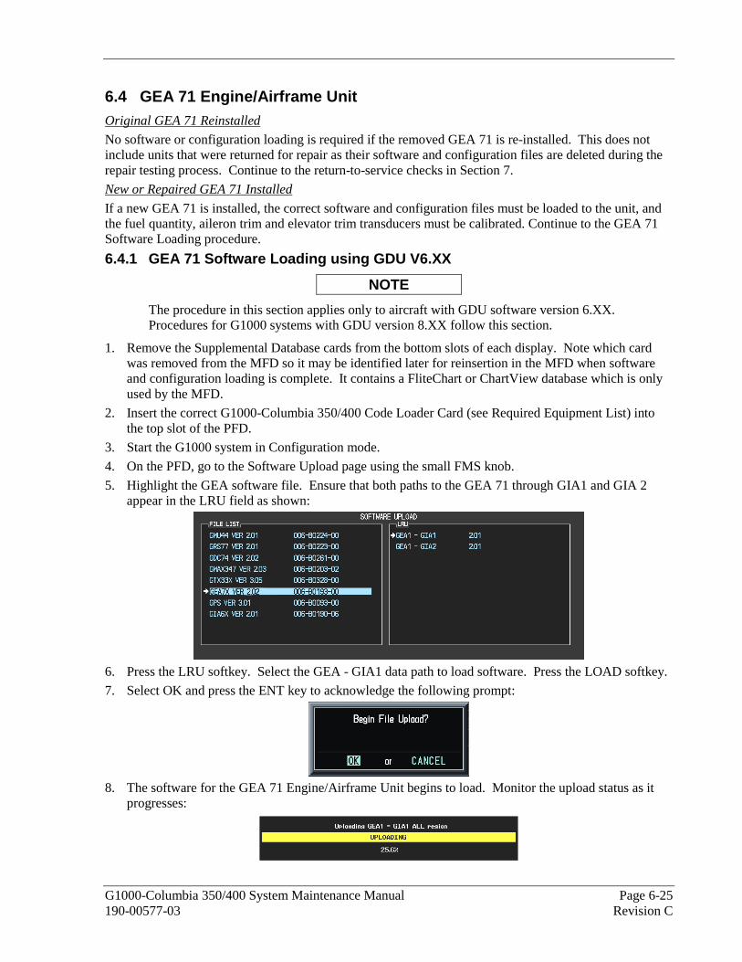
G1000-Columbia 350/400 System Maintenance Manual Page 6-25 190-00577-03 Revision C
6.4 GEA 71 Engine/Airframe Unit Original GEA 71 Reinstalled
No software or configuration loading is required if the removed GEA 71 is re-installed. This does not include units that were returned for repair as their software and configuration files are deleted during the repair testing process. Continue to the return-to-service checks in Section 7.
New or Repaired GEA 71 Installed
If a new GEA 71 is installed, the correct software and configuration files must be loaded to the unit, and the fuel quantity, aileron trim and elevator trim transducers must be calibrated. Continue to the GEA 71 Software Loading procedure.
6.4.1 GEA 71 Software Loading using GDU V6.XX
NOTE
The procedure in this section applies only to aircraft with GDU software version 6.XX. Procedures for G1000 systems with GDU version 8.XX follow this section.
1. Remove the Supplemental Database cards from the bottom slots of each display. Note which card was removed from the MFD so it may be identified later for reinsertion in the MFD when software and configuration loading is complete. It contains a FliteChart or ChartView database which is only used by the MFD.
2. Insert the correct G1000-Columbia 350/400 Code Loader Card (see Required Equipment List) into the top slot of the PFD.
3. Start the G1000 system in Configuration mode.
4. On the PFD, go to the Software Upload page using the small FMS knob.
5. Highlight the GEA software file. Ensure that both paths to the GEA 71 through GIA1 and GIA 2 appear in the LRU field as shown:
6. Press the LRU softkey. Select the GEA - GIA1 data path to load software. Press the LOAD softkey.
7. Select OK and press the ENT key to acknowledge the following prompt:
8. The software for the GEA 71 Engine/Airframe Unit begins to load. Monitor the upload status as it
progresses:

Page 6-26 G1000-Columbia 350/400 System Maintenance Manual Revision C 190-00577-03
9. After the files finish loading, press ENT to acknowledge the following prompt:
10. Check the SUMMARY field to ensure the all software loads are ‘COMPLETE’.
11. De-activate the cursor.
12. Go to the System Status page.
13. Activate the cursor and highlight ‘GEA1 – GIA1’ in the LRU window.
14. Verify that the reported part number and version of the software file matches the data in the Required Equipment List.
15. Continue to the GEA 71 Configuration Loading procedure.
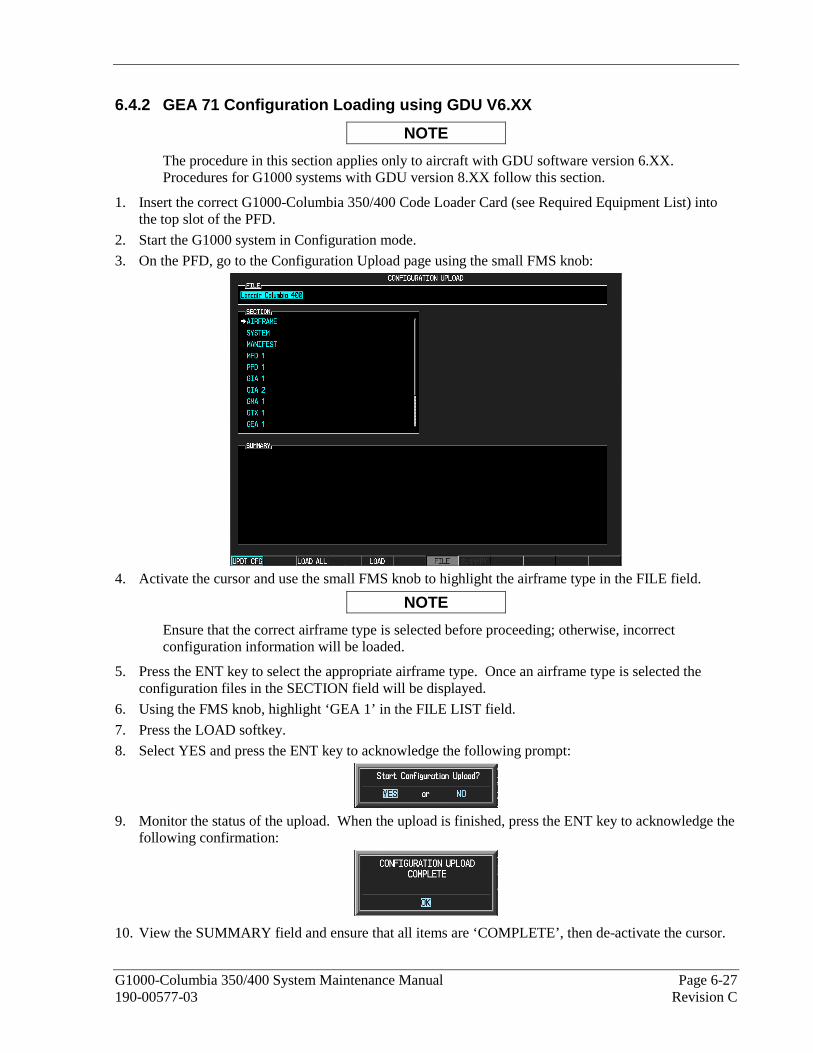
G1000-Columbia 350/400 System Maintenance Manual Page 6-27 190-00577-03 Revision C
6.4.2 GEA 71 Configuration Loading using GDU V6.XX
NOTE
The procedure in this section applies only to aircraft with GDU software version 6.XX. Procedures for G1000 systems with GDU version 8.XX follow this section.
1. Insert the correct G1000-Columbia 350/400 Code Loader Card (see Required Equipment List) into the top slot of the PFD.
2. Start the G1000 system in Configuration mode.
3. On the PFD, go to the Configuration Upload page using the small FMS knob:
4. Activate the cursor and use the small FMS knob to highlight the airframe type in the FILE field.
NOTE
Ensure that the correct airframe type is selected before proceeding; otherwise, incorrect configuration information will be loaded.
5. Press the ENT key to select the appropriate airframe type. Once an airframe type is selected the configuration files in the SECTION field will be displayed.
6. Using the FMS knob, highlight ‘GEA 1’ in the FILE LIST field.
7. Press the LOAD softkey.
8. Select YES and press the ENT key to acknowledge the following prompt:
9. Monitor the status of the upload. When the upload is finished, press the ENT key to acknowledge the
following confirmation:
10. View the SUMMARY field and ensure that all items are ‘COMPLETE’, then de-activate the cursor.

Page 6-28 G1000-Columbia 350/400 System Maintenance Manual Revision C 190-00577-03
11. After the software and configuration files are loaded, turn off the system and reinsert the Supplemental Database Cards in the bottom slot of each display. Be sure to insert the card removed from the MFD back into the MFD.
12. Continue to the GEA 71 Test procedure.
6.4.3 GEA 71 Software Load and Configuration using GDU V8.XX
NOTE
The procedure in this section applies only to aircraft with GDU software version 8.XX. Procedures for G1000 systems with GDU version 6.XX precede this section.
1. On the PFD, go to the System Upload page using the small FMS knob.
2. Activate the cursor and use the small FMS knob to highlight the airframe type in the AIRFRAME field. Select the appropriate aircraft type (C400 or C350) and press the ENT key.
NOTE
Ensure that the correct airframe type is selected before proceeding; otherwise, incorrect configuration information will be loaded.
3. Once an airframe type is selected the cursor moves to the FILE window. Rotate the small FMS knob to activate the drop-down menu. Three FQIS fuel tank options are available: 49 gallon (non-adjusted); 49 gallon (adjusted); 51 gallon. Confirm the serial number of the aircraft prior to selection as well as inspect logbooks for field upgrades according to the following table.
C350 C400 Comments
49 Gallon (non-adjusted)
42502 - 42564 41563 - 41757 Verify logbooks for compliance with Columbia Service Letter SL-07-008B
49 Gallon (adjusted)
42565 - 42567 41758 - 41799
51 Gallon 42568 and higher 41800 and higher Inspect fuel tank placard
If the aircraft is a Columbia 350 within the serial number range of 42502-42564 or a Columbia 400 within the serial number range of 41563-41757, confirm the FQIS fuel tank option by referencing the aircrafts logbooks. Compliance with Columbia Service Letter number SL-07-008B requires the selection of “49 gallon adjusted”. Columbia aircraft with 51 gallon tanks can be verified by inspection of the fuel tank placard.

G1000-Columbia 350/400 System Maintenance Manual Page 6-29 190-00577-03 Revision C
NOTE
At this step, select to load WAAS or non-WAAS G1000 software.
4. The PRODUCT window will populate and display software and configuration file information for each G1000 LRU. The LRU VERS column shows the currently loaded software version in the LRU, whereas the CARD VERS column shows the LRU software version stored on the Loader Card. Each check designates a file to be loaded to the G1000.
By default, if an inequality between the LRU and CARD columns exists, the SOFTWARE CONFIGURATION boxes will be pre-selected (checked). By default all of the CONFIGURATION boxes will be pre-selected.
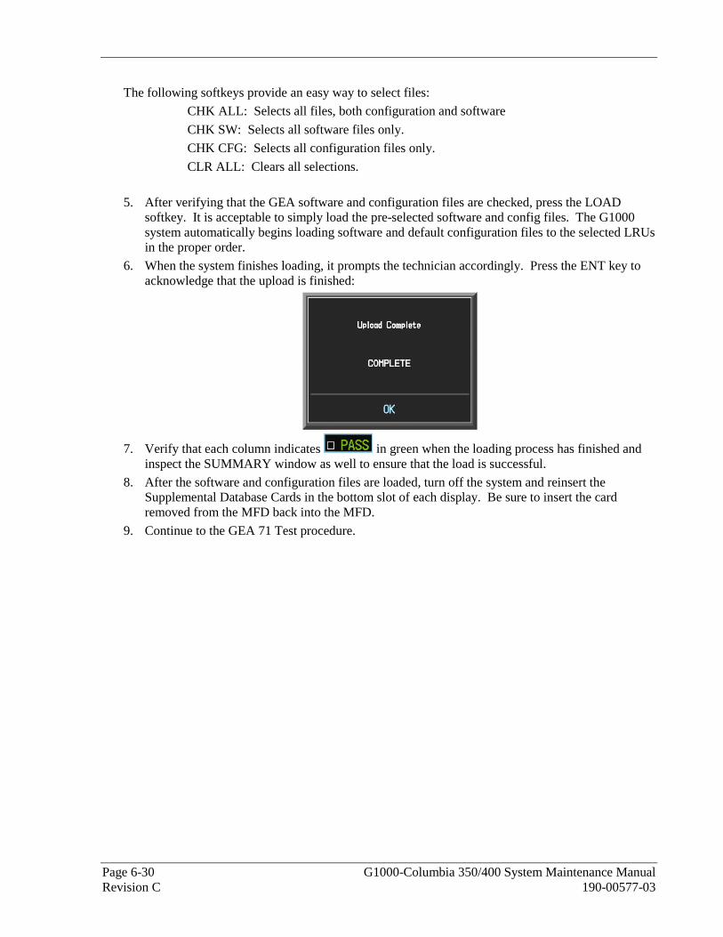
Page 6-30 G1000-Columbia 350/400 System Maintenance Manual Revision C 190-00577-03
The following softkeys provide an easy way to select files:
CHK ALL: Selects all files, both configuration and software
CHK SW: Selects all software files only.
CHK CFG: Selects all configuration files only.
CLR ALL: Clears all selections.
5. After verifying that the GEA software and configuration files are checked, press the LOAD softkey. It is acceptable to simply load the pre-selected software and config files. The G1000 system automatically begins loading software and default configuration files to the selected LRUs in the proper order.
6. When the system finishes loading, it prompts the technician accordingly. Press the ENT key to acknowledge that the upload is finished:
7. Verify that each column indicates in green when the loading process has finished and inspect the SUMMARY window as well to ensure that the load is successful.
8. After the software and configuration files are loaded, turn off the system and reinsert the Supplemental Database Cards in the bottom slot of each display. Be sure to insert the card removed from the MFD back into the MFD.
9. Continue to the GEA 71 Test procedure.

G1000-Columbia 350/400 System Maintenance Manual Page 6-31 190-00577-03 Revision C
6.4.4 GEA 71 Calibration using GDU V6.XX
NOTE
The procedure in this section applies only to aircraft with GDU software version 6.XX. Procedures for G1000 systems with GDU version 8.XX follow this section.
The GEA 71 provides a means to recalibrate the system in the event that a sensor is replaced. This section contains the procedures necessary to accomplish recalibration.
NOTE
If the GEA 71 is replaced with a new unit, these calibration procedures are not required.
6.4.4.1 Fuel Quantity Transducer Calibration using GDU V6.XX
1. Level the aircraft, following instructions in the Columbia 350/400 Airplane Maintenance Manual.
2. With the aircraft in a dry-tank configuration, fill each fuel tank with 4.0 gallons fuel (unusable fuel, refer to Columbia 350/400 POH/AFM). Use proper precautions when handling fuel. Ensure that the aircraft is grounded correctly and that there is adequate ventilation.
NOTE
After the addition of fuel, tap the wing near the fuel senders or use some other appropriate method to ensure that the fuel senders are not “sticking” prior to doing any calibration or taking any measurements. This is especially important when doing the EMPTY calibrations.
3. Go to the CAL Page Group on the PFD.
4. The Fuel Calibration page (1st page in CAL group) will be shown by default:
5. This page is protected and requires a keystroke password to perform the calibration. Press the following softkeys in sequence:

Page 6-32 G1000-Columbia 350/400 System Maintenance Manual Revision C 190-00577-03
a) softkey 12 (Far Right softkey) b) softkey 11 c) softkey 10 d) softkey 9
6. Press the L RESET softkey. Press ENT to acknowledge the following prompt:
7. Ensure that the CAL VAL indication for the Left 1 Sub-Tank is stable.
8. Press the L EMPTY softkey.
9. Press the R RESET softkey. Press ENT to acknowledge the following prompt:
10. Ensure that the CAL VAL indication for the Right 1 Sub-Tank is stable.
11. Press the R EMPTY softkey.
12. Fill each fuel tank with an additional 49.0 ± 0.1 gallons usable fuel.
13. Ensure that the CAL VAL indication for the Left 1 Sub-Tank is stable.
14. Press the L FULL softkey.
15. Ensure that the CAL VAL indication for the Right 1 Sub-Tank is stable.
16. Press the R FULL softkey.
17. Completely drain the fuel from the left and right tanks.
18. Fill each fuel tank with 4 gallons fuel (unusable fuel, refer to Columbia 400 AFM) and ensure that the CAL VAL indications are stable.
19. Observe the CAL VAL indications for both Right 1 and Left 1 Sub-Tanks and record the readings in the following tables. The CAL VAL values should fall between -0.5 and 0.5 as shown in the following examples:
LEFT 1 SUB-TANK
Calibrated Value (CAL VAL) Range Actual Useable
Fuel Minimum Allowed
Indication
Maximum Allowed
Indication
Record Actual Indicated CAL VAL
Here
Is CAL VAL Within Specified Range?
Yes / No
0 -0.5 0.5

G1000-Columbia 350/400 System Maintenance Manual Page 6-33 190-00577-03 Revision C
RIGHT 1 SUB-TANK
Calibrated Value (CAL VAL) Range Actual Useable
Fuel Minimum Allowed
Indication
Maximum Allowed
Indication
Record Actual Indicated CAL VAL
Here
Is CAL VAL Within Specified Range?
Yes / No
0 -0.5 0.5
20. Using the large FMS knob, select the GEA STATUS page (2nd page in the GEA page group). GEA 1 will be shown by default.
21. Press the DSCRT softkey to select the Discrete Inputs status page.
NOTE
Unless specified, the status of other discrete inputs may not match the figure above and does not matter for this portion of the test.
22. Verify that the boxes beside the “1A LOW MAIN FUEL L” (low fuel quantity left) and “2A LOW MAIN FUEL R” (low fuel quantity right) are green.
23. Fill each fuel tank with an additional 5.0 ± 0.1 gallons usable fuel.
24. Continue to slowly add fuel to each tank one measured gallon at a time. Stop adding fuel when the associated LOW MAIN FUEL L or LOW MAIN FUEL R box changes from green to black.
25. Using the large FMS knob, select the FUEL CALIBRATION page (1st page in CAL page group).
26. In the table below, record the amount of usable fuel added to each tank. Also record the CAL VAL indications for both Right 1 and Left 1 Sub-Tanks. The amount of fuel added to each tank to turn the discrete off must be 8 ± 2 gal, and the CAL VAL values should be within ±2 gallon of the actual amount of usable fuel added.
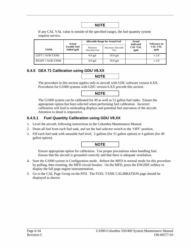
Page 6-34 G1000-Columbia 350/400 System Maintenance Manual Revision C 190-00577-03
NOTE
If any CAL VAL value is outside of the specified ranges, the fuel quantity system requires service.
Allowable Range for Actual Fuel
TANK
Actual Useable Fuel Added (gal)
Minimum Allowable Fuel
Maximum Allowable Fuel
Actual Indicated CAL VAL
(gal)
Tolerance on CAL VAL
(gal)
LEFT 1 SUB-TANK 6.0 gal 10.0 gal ± 2.0
RIGHT 1 SUB-TANK 6.0 gal 10.0 gal ± 2.0
6.4.5 GEA 71 Calibration using GDU V8.XX
NOTE
The procedure in this section applies only to aircraft with GDU software version 8.XX. Procedures for G1000 systems with GDU version 6.XX precede this section.
NOTE
The G1000 system can be calibrated for 49 as well as 51 gallon fuel tanks. Ensure the appropriate option has been selected when performing fuel calibration. Incorrect calibration will lead to misleading displays and potential fuel starvation of the aircraft. Attention to detail is imperative.
6.4.5.1 Fuel Quantity Calibration using GDU V8.XX
1. Level the aircraft, following instructions in the Columbia Maintenance Manual.
2. Drain all fuel from each fuel tank, and set the fuel selector switch to the ‘OFF’ position.
3. Fill each fuel tank with unusable fuel level, 2 gallons (for 51 gallon option) or 4 gallons (for 49 gallon option).
NOTE
Ensure appropriate option for calibration. Use proper precautions when handling fuel. Ensure that the aircraft is grounded correctly and that there is adequate ventilation.
4. Start the G1000 system in Configuration mode. Reboot the MFD in normal mode for this procedure by pulling, then resetting, the MFD circuit breaker. On the MFD, press the ENGINE softkey to display the full page engine instrumentation.
5. Go to the CAL Page Group on the PFD. The FUEL TANK CALIBRATION page should be displayed as shown:
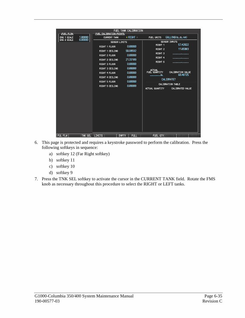
G1000-Columbia 350/400 System Maintenance Manual Page 6-35 190-00577-03 Revision C
6. This page is protected and requires a keystroke password to perform the calibration. Press the following softkeys in sequence:
a) softkey 12 (Far Right softkey)
b) softkey 11
c) softkey 10
d) softkey 9
7. Press the TNK SEL softkey to activate the cursor in the CURRENT TANK field. Rotate the FMS knob as necessary throughout this procedure to select the RIGHT or LEFT tanks.

Page 6-36 G1000-Columbia 350/400 System Maintenance Manual Revision C 190-00577-03
6.4.5.2 Empty Calibration using GDU V8.XX
1. Verify that unusable fuel has been added to both tanks per section 6.4.5.1. Allow both fuel probes to stabilize for at least 2 minutes.
2. Select the LEFT tank on the PFD.
3. Press the EMPTY softkey. The cursor will automatically activate and select the CALIBRATE? option. The calibrated value setting will default to 00.00.
4. Press the ENT key. A prompt appears requesting overwrite acknowledgement. Select YES and press the ENT key. The G1000 system will ‘zero’ the actual fuel quantity value to be displayed.
5. Select the RIGHT tank.
6. Press the EMPTY softkey. The cursor will automatically activate and select the CALIBRATE? option. The calibrated value setting will default to 00.00.
7. Press the ENT key. A prompt appears requesting overwrite acknowledgement. Select YES and press the ENT key. The G1000 system will ‘zero’ the actual fuel quantity value to be displayed.
8. Observe the CALIBRATED TOTAL indication for the RIGHT tank. Verify that it remains at 0.00 (+/- 0.5 gallons).
9. Select the LEFT tank. Observe the CALIBRATED TOTAL indication for the LEFT tank. Verify that it remains at 0.00 (+/- 0.5 gallons).
10. On the MFD, verify the fuel quantity indicators correctly point to ‘0’.
6.4.5.3 5 Gallon Calibration using GDU V8.XX
1. Fill each fuel tank with 5 ± 0.1 gallons usable fuel.
2. Allow the fuel probes to stabilize at least 2 minutes before continuing.
3. Record the CALIBRATED TOTAL indication for the RIGHT tank. This is the pre-calibrated value. RIGHT 1 SUB-TANK
Calibration Value Range Actual Useable
Fuel Minimum Allowed Indication
Maximum Allowed Indication
Record Actual Indicated Calibration Value
Here
Is Calibration Value Within Specified Range?
Yes / No
0 -0.5 0.5
4. Select the LEFT tank. Record the CALIBRATED TOTAL indication for the LEFT tank. This is the pre-calibrated value.
LEFT 1 SUB-TANK
Calibration Value Range Actual Useable
Fuel Minimum Allowed Indication
Maximum Allowed Indication
Record Actual Indicated Calibration Value
Here
Is Calibration Value Within Specified Range?
Yes / No
0 -0.5 0.5
5. With the LEFT tank selected, highlight the ACTUAL FUEL QUANTITY field and enter 5.00 gallons.
6. Press the ENT key. The cursor automatically selects the CALIBRATE? option.
7. Press the ENT key again to calibrate the 5 gallon point.
8. Verify a 5.00 gallon point appears in the CALIBRATION TABLE.
9. Verify that the CALIBRATED TOTAL value indicates 5.00 (+/- 0.5 gallons).
10. Select the RIGHT tank. Highlight the ACTUAL FUEL QUANTITY field and enter 5.00 gallons.
11. Press the ENT key. The cursor automatically selects the CALIBRATE? option.

G1000-Columbia 350/400 System Maintenance Manual Page 6-37 190-00577-03 Revision C
12. Press the ENT key again to calibrate the 5 gallon point.
13. Verify a 5.00 gallon point appears in the CALIBRATION TABLE.
14. Verify that the CALIBRATED TOTAL value indicates 5.00 (+/- 0.5 gallons).
6.4.5.4 Low Fuel Level Check using GDU V8.XX
1. Using the large FMS knob, select the GEA STATUS page (2nd page in the GEA page group). GEA 1 will be shown by default.
2. Press the DSCRT softkey to select the Discrete Inputs status page.
NOTE
Unless specified, the status of other discrete inputs may not match the figure above and does not matter for this portion of the test.
3. Verify that the boxes beside the “1A LOW MAIN FUEL L” (low fuel quantity left) and “2A LOW MAIN FUEL R” (low fuel quantity right) are green.
4. Continue to slowly add fuel to each tank one measured gallon at a time. Stop adding fuel when the associated LOW MAIN FUEL L or LOW MAIN FUEL R box changes from green to black .
5. Using the large FMS knob, select the FUEL CALIBRATION page (1st page in CAL page group).
6. In the table below, record the amount of usable fuel added to each tank. Also record the Calibration Value indications for both Right 1 and Left 1 Sub-Tanks. The amount of fuel added to each tank to turn the discrete off must be 8 ± 2 gal, and the Calibration Values should be within ±2 gallon of the actual amount of usable fuel added.

Page 6-38 G1000-Columbia 350/400 System Maintenance Manual Revision C 190-00577-03
NOTE
If any calibration value is outside of the specified ranges, the fuel quantity system requires service.
Allowable Range for Actual Fuel
TANK
Actual Useable
Fuel Added (gal)
Minimum Allowable Fuel
Maximum Allowable Fuel
Actual Indicated
Calibration Value (gal)
Tolerance on Calibration
Value (gal)
LEFT 1 SUB-TANK 6.0 gal 10.0 gal ± 2.0
RIGHT 1 SUB-TANK 6.0 gal 10.0 gal ± 2.0
6.4.5.5 Full Calibration using GDU V8.XX
1. Verify that both fuel tanks are full. Allow both fuel probes to stabilize for at least 2 minutes.
2. Select the LEFT tank on the PFD.
3. Press the FULL softkey. The cursor will automatically activate and select the CALIBRATE? option. The calibrated value setting will default to 49.00 or 51.00 as appropriate.
4. Press the ENT key. A prompt appears requesting overwrite acknowledgement. Select YES and press the ENT key. The G1000 system will set the actual fuel quantity value to be full.
5. Select the RIGHT tank.
6. Press the FULL softkey. The cursor will automatically activate and select the CALIBRATE? option. The calibrated value setting will default to 49.00 or 51.00.as appropriate.
7. Press the ENT key. A prompt appears requesting overwrite acknowledgement. Select YES and press the ENT key. The G1000 system will set the actual fuel quantity value to be full.
8. Observe the CALIBRATED TOTAL indication for the RIGHT tank. Verify that it remains at 49.00 or 51.00 as appropriate.
9. Select the LEFT tank. Observe the CALIBRATED TOTAL indication for the LEFT tank. Verify that it remains at 49.00 or 51.00 as appropriate.
10. On the MFD, verify the fuel quantity indicators correctly point to ‘F’.

G1000-Columbia 350/400 System Maintenance Manual Page 6-39 190-00577-03 Revision C
6.4.6 Aileron and Elevator Trim Calibration
NOTE
Before conducting the flaps and trim calibration procedure, ensure that the elevator, elevator trim, aileron and aileron trim systems have been properly rigged and adjusted.
1. Go to the CAL Page Group on the PFD.
2. Select the Flaps and Trim Calibration page (3rd page in CAL group), shown below:
Figure 6-5. Aileron and Elevator Trim Calibration
3. This page is protected and requires a keystroke password to perform the calibration. Press the following softkeys in sequence:
a) softkey 1 (Far Left softkey) b) softkey 2 c) softkey 3 d) softkey 4
4. Press the Elevator Trim RESET softkey (see Figure 6-5). Press ENT to acknowledge the following prompt after the RESET softkey is pressed:
5. Use the trim hat switch to run the elevator trim to the FULL UP position.
6. Press the Elevator Trim UP softkey on the PFD (see Figure 6-5).
7. Run the elevator trim to the FULL DOWN position. Press the Elevator Trim DN softkey on the PFD.
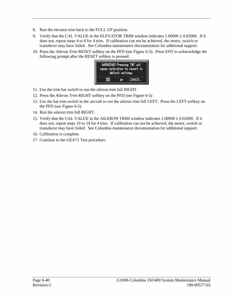
Page 6-40 G1000-Columbia 350/400 System Maintenance Manual Revision C 190-00577-03
8. Run the elevator trim back to the FULL UP position.
9. Verify that the CAL VALUE in the ELEVATOR TRIM window indicates 1.00000 ± 0.02000. If it does not, repeat steps 4 to 8 for 4 tries. If calibration can not be achieved, the motor, switch or transducer may have failed. See Columbia maintenance documentation for additional support.
10. Press the Aileron Trim RESET softkey on the PFD (see Figure 6-5). Press ENT to acknowledge the following prompt after the RESET softkey is pressed:
11. Use the trim hat switch to run the aileron trim full RIGHT.
12. Press the Aileron Trim RIGHT softkey on the PFD (see Figure 6-5)
13. Use the hat trim switch in the aircraft to run the aileron trim full LEFT. Press the LEFT softkey on the PFD (see Figure 6-5).
14. Run the aileron trim full RIGHT.
15. Verify that the CAL VALUE in the AILERON TRIM window indicates 1.00000 ± 0.02000. If it does not, repeat steps 10 to 14 for 4 tries. If calibration can not be achieved, the motor, switch or transducer may have failed. See Columbia maintenance documentation for additional support.
16. Calibration is complete.
17. Continue to the GEA71 Test procedure.
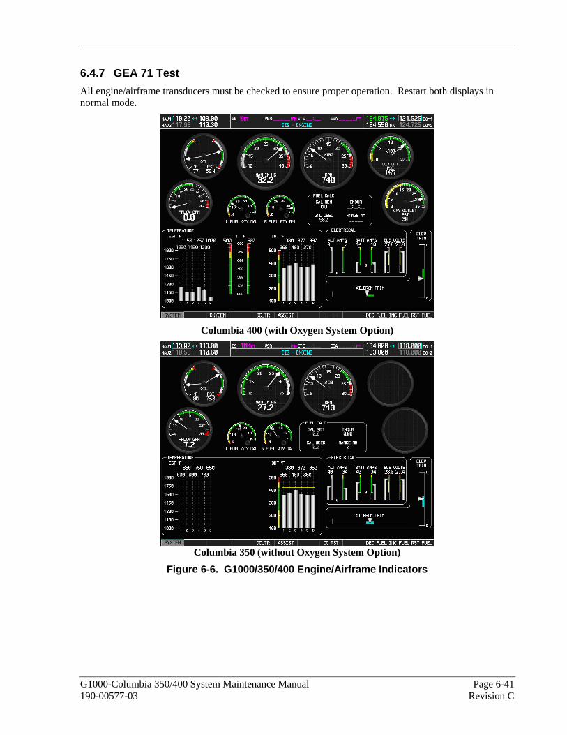
G1000-Columbia 350/400 System Maintenance Manual Page 6-41 190-00577-03 Revision C
6.4.7 GEA 71 Test
All engine/airframe transducers must be checked to ensure proper operation. Restart both displays in normal mode.
Columbia 400 (with Oxygen System Option)
Columbia 350 (without Oxygen System Option)
Figure 6-6. G1000/350/400 Engine/Airframe Indicators
Page 6-42 G1000-Columbia 350/400 System Maintenance Manual Revision C 190-00577-03
On the MFD, check the indication for each of the sensor or monitor inputs with the aircraft engine off. Observe the ‘Engine’ page by using the SYSTEM softkey on the MFD. Observe the following sensor indications (see Figure 6-6):
Engine Page:
Sensor Reading with Aircraft Engine Off and Cool • OIL TEMP Ambient
• OIL PRESS Approximately ‘0’ • MAN IN HG Atmospheric Pressure
• RPM ‘0’
• OXY QTY (if installed) ‘2000’ with fully filled bottles • FFLOW GPH ‘0’
• FUEL QTY GAL ‘F’ with fully fueled tanks (Left and Right)
• OXY OUTLET (if installed) Low • EGT Ambient
• TIT (Columbia 400 only) Ambient
• CHT Ambient. • ALT AMPS ‘0’ if on external power
• BATT AMPS Negative if battery is discharging
• BUS VOLTS GPU Voltage if on external power and crosstie closed. • AILERON TRIM Centered if aileron trim tab is centered.
• ELEVATOR TRIM Centered if elevator trim tab is centered.
If no other service is to be performed, continue to the return-to-service checks in Section 7.

G1000-Columbia 350/400 System Maintenance Manual Page 6-43 190-00577-03 Revision C
6.5 GTX 33 Transponder Original GTX 33 is Reinstalled
No software or configuration loading is required if the removed GTX 33 is re-installed. This does not include units that were returned for repair as their software and configuration files are deleted during the repair testing process. Continue to the GTX 33 Test procedure.
New or Repaired GTX 33 is Installed
If a new GTX 33 is installed, the correct software and configuration files must be loaded to the unit. Continue to the GTX 33 Software Loading procedure.
6.5.1 GTX 33 Software Loading using GDU V6.XX
NOTE
The procedure in this section applies only to aircraft with GDU software version 6.XX. Procedures for G1000 systems with GDU version 8.XX follow this section.
1. Remove the Supplemental Database cards from the bottom slots of each display. Note which card was removed from the MFD so it may be identified later for reinsertion in the MFD when software and configuration loading is complete. It contains a FliteChart or ChartView database which is only used by the MFD.
2. Insert the correct G1000-Columbia 350/400 Code Loader Card (see Required Equipment List) into the top slot of the PFD.
3. Start the G1000 system in Configuration mode.
4. On the PFD, go to the Software Upload page using the FMS knob.
5. Highlight the GTX software file. Ensure that both paths to the GTX 33 through GIA1 and GIA2 appear in the LRU field as shown:
6. Press the LRU softkey. Select the GTX1 - GIA1 data path to load software. Press the LOAD
softkey.
7. Select OK and press the ENT key to acknowledge the following prompt:
8. The software for the GTX 33 transponder begins to load. Monitor the upload status as it progresses:
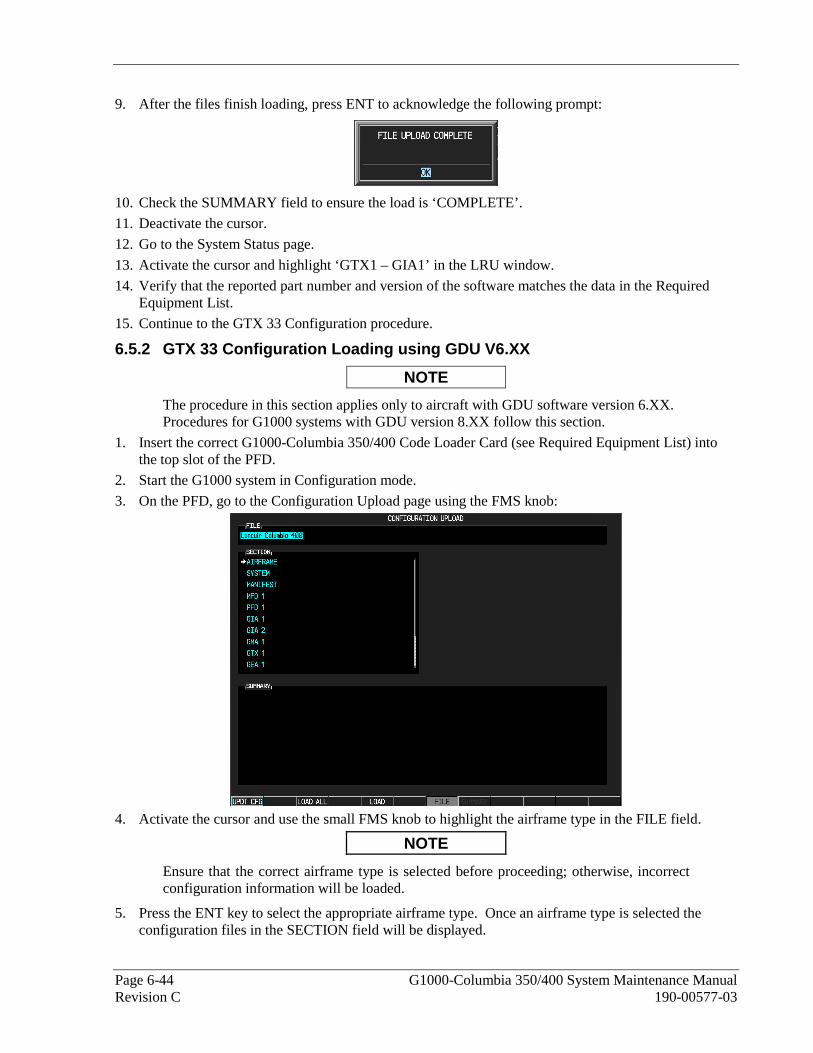
Page 6-44 G1000-Columbia 350/400 System Maintenance Manual Revision C 190-00577-03
9. After the files finish loading, press ENT to acknowledge the following prompt:
10. Check the SUMMARY field to ensure the load is ‘COMPLETE’.
11. Deactivate the cursor.
12. Go to the System Status page.
13. Activate the cursor and highlight ‘GTX1 – GIA1’ in the LRU window.
14. Verify that the reported part number and version of the software matches the data in the Required Equipment List.
15. Continue to the GTX 33 Configuration procedure.
6.5.2 GTX 33 Configuration Loading using GDU V6.XX
NOTE
The procedure in this section applies only to aircraft with GDU software version 6.XX. Procedures for G1000 systems with GDU version 8.XX follow this section.
1. Insert the correct G1000-Columbia 350/400 Code Loader Card (see Required Equipment List) into the top slot of the PFD.
2. Start the G1000 system in Configuration mode.
3. On the PFD, go to the Configuration Upload page using the FMS knob:
4. Activate the cursor and use the small FMS knob to highlight the airframe type in the FILE field.
NOTE
Ensure that the correct airframe type is selected before proceeding; otherwise, incorrect configuration information will be loaded.
5. Press the ENT key to select the appropriate airframe type. Once an airframe type is selected the configuration files in the SECTION field will be displayed.
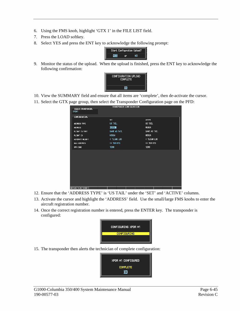
G1000-Columbia 350/400 System Maintenance Manual Page 6-45 190-00577-03 Revision C
6. Using the FMS knob, highlight ‘GTX 1’ in the FILE LIST field.
7. Press the LOAD softkey.
8. Select YES and press the ENT key to acknowledge the following prompt:
9. Monitor the status of the upload. When the upload is finished, press the ENT key to acknowledge the
following confirmation:
10. View the SUMMARY field and ensure that all items are ‘complete’, then de-activate the cursor.
11. Select the GTX page group, then select the Transponder Configuration page on the PFD:
12. Ensure that the ‘ADDRESS TYPE’ is ‘US TAIL’ under the ‘SET’ and ‘ACTIVE’ columns.
13. Activate the cursor and highlight the ‘ADDRESS’ field. Use the small/large FMS knobs to enter the aircraft registration number.
14. Once the correct registration number is entered, press the ENTER key. The transponder is configured:
15. The transponder then alerts the technician of complete configuration:
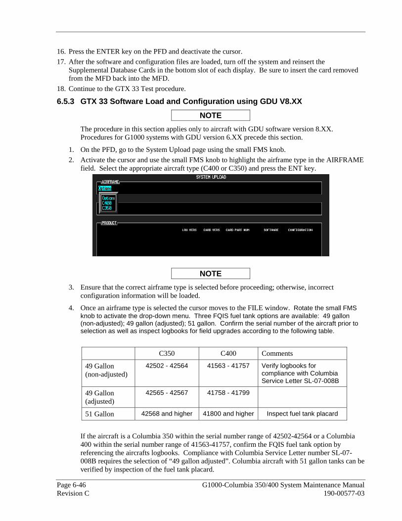
Page 6-46 G1000-Columbia 350/400 System Maintenance Manual Revision C 190-00577-03
16. Press the ENTER key on the PFD and deactivate the cursor.
17. After the software and configuration files are loaded, turn off the system and reinsert the Supplemental Database Cards in the bottom slot of each display. Be sure to insert the card removed from the MFD back into the MFD.
18. Continue to the GTX 33 Test procedure.
6.5.3 GTX 33 Software Load and Configuration using GDU V8.XX
NOTE
The procedure in this section applies only to aircraft with GDU software version 8.XX. Procedures for G1000 systems with GDU version 6.XX precede this section.
1. On the PFD, go to the System Upload page using the small FMS knob.
2. Activate the cursor and use the small FMS knob to highlight the airframe type in the AIRFRAME field. Select the appropriate aircraft type (C400 or C350) and press the ENT key.
NOTE
3. Ensure that the correct airframe type is selected before proceeding; otherwise, incorrect configuration information will be loaded.
4. Once an airframe type is selected the cursor moves to the FILE window. Rotate the small FMS knob to activate the drop-down menu. Three FQIS fuel tank options are available: 49 gallon (non-adjusted); 49 gallon (adjusted); 51 gallon. Confirm the serial number of the aircraft prior to selection as well as inspect logbooks for field upgrades according to the following table.
C350 C400 Comments
49 Gallon (non-adjusted)
42502 - 42564 41563 - 41757 Verify logbooks for compliance with Columbia Service Letter SL-07-008B
49 Gallon (adjusted)
42565 - 42567 41758 - 41799
51 Gallon 42568 and higher 41800 and higher Inspect fuel tank placard
If the aircraft is a Columbia 350 within the serial number range of 42502-42564 or a Columbia 400 within the serial number range of 41563-41757, confirm the FQIS fuel tank option by referencing the aircrafts logbooks. Compliance with Columbia Service Letter number SL-07-008B requires the selection of “49 gallon adjusted”. Columbia aircraft with 51 gallon tanks can be verified by inspection of the fuel tank placard.

G1000-Columbia 350/400 System Maintenance Manual Page 6-47 190-00577-03 Revision C
NOTE
At this step, select to load WAAS or non-WAAS G1000 software.
5. The PRODUCT window will populate and display software and configuration file information for each G1000 LRU. The LRU VERS column shows the currently loaded software version in the LRU, whereas the CARD VERS column shows the LRU software version stored on the Loader Card. Each check designates a file to be loaded to the G1000.
By default, if an inequality between the LRU and CARD columns exists, the SOFTWARE CONFIGURATION boxes will be pre-selected (checked). By default all of the CONFIGURATION boxes will be pre-selected.

Page 6-48 G1000-Columbia 350/400 System Maintenance Manual Revision C 190-00577-03
The following softkeys provide an easy way to select files:
CHK ALL: Selects all files, both configuration and software
CHK SW: Selects all software files only.
CHK CFG: Selects all configuration files only.
CLR ALL: Clears all selections.
6. After verifying that the GTX software and configuration files are checked, press the LOAD softkey. It is acceptable to simply load the pre-selected software and config files. The G1000 system automatically begins loading software and default configuration files to the selected LRUs in the proper order.
7. When the system finishes loading, it prompts the technician accordingly. Press the ENT key to acknowledge that the upload is finished:
8. Verify that each column indicates in green when the loading process has finished and inspect the SUMMARY window as well to ensure that the load is successful.
9. Select the GTX page group, then select the Transponder Configuration page on the PFD:
10. Ensure that the ‘ADDRESS TYPE’ is ‘US TAIL’ under the ‘SET’ and ‘ACTIVE’ columns.
11. Activate the cursor and highlight the ‘ADDRESS’ field. Use the small/large FMS knobs to enter the aircraft registration number.
12. Once the correct registration number is entered, press the ENTER key. The transponder is configured:
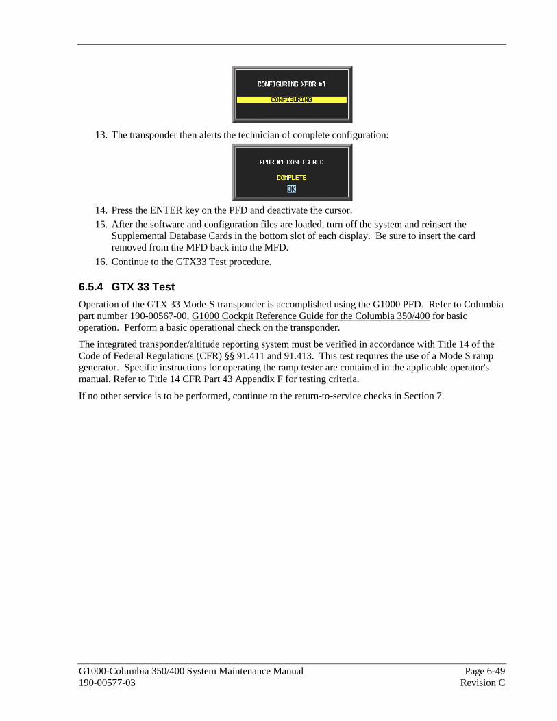
G1000-Columbia 350/400 System Maintenance Manual Page 6-49 190-00577-03 Revision C
13. The transponder then alerts the technician of complete configuration:
14. Press the ENTER key on the PFD and deactivate the cursor.
15. After the software and configuration files are loaded, turn off the system and reinsert the Supplemental Database Cards in the bottom slot of each display. Be sure to insert the card removed from the MFD back into the MFD.
16. Continue to the GTX33 Test procedure. 6.5.4 GTX 33 Test
Operation of the GTX 33 Mode-S transponder is accomplished using the G1000 PFD. Refer to Columbia part number 190-00567-00, G1000 Cockpit Reference Guide for the Columbia 350/400 for basic operation. Perform a basic operational check on the transponder.
The integrated transponder/altitude reporting system must be verified in accordance with Title 14 of the Code of Federal Regulations (CFR) §§ 91.411 and 91.413. This test requires the use of a Mode S ramp generator. Specific instructions for operating the ramp tester are contained in the applicable operator's manual. Refer to Title 14 CFR Part 43 Appendix F for testing criteria.
If no other service is to be performed, continue to the return-to-service checks in Section 7.

Page 6-50 G1000-Columbia 350/400 System Maintenance Manual Revision C 190-00577-03
6.6 GDC 74A Air Data Computer Original GDC 74A is Reinstalled
No software or configuration loading is required if the removed GDC 74A is re-installed. This does not include units that were returned for repair as their software and configuration files are deleted during the repair testing process. Continue to the GDC 74A Test procedure.
New or Repaired GDC 74A is Installed
If a new GDC 74A is installed, the correct software and configuration files must be loaded to the unit. Continue to the GDC 74A Software Loading procedure.
6.6.1 GDC 74A Software Loading using GDU V6.XX
NOTE
The procedure in this section applies only to aircraft with GDU software version 6.XX. Procedures for G1000 systems with GDU version 8.XX follow this section.
1. Remove the Supplemental Database cards from the bottom slots of each display. Note which card was removed from the MFD so it may be identified later for reinsertion in the MFD when software and configuration loading is complete. It contains a FliteChart or ChartView database which is only used by the MFD.
2. Insert the correct G1000-Columbia 350/400 Code Loader Card (see Required Equipment List) into the top slot of the PFD.
3. Start the G1000 system in Configuration mode.
4. On the PFD, go to the Software Upload page using the FMS knob.
5. Highlight the GDC software file. Ensure that GDC to GIA data path appears in the LRU field as shown:
6. Press the LOAD softkey.
7. Select OK and press the ENT key to acknowledge the following prompt:
8. The software for the GDC 74A Air Data Computer begins to load. Monitor the upload status as it
progresses:
9. After the files finish loading, press ENT to acknowledge the following prompt:

G1000-Columbia 350/400 System Maintenance Manual Page 6-51 190-00577-03 Revision C
10. Check the SUMMARY field to ensure the load is ‘COMPLETE’.
11. Deactivate the cursor.
12. Go to the System Status page.
13. Activate the cursor and highlight ‘GDC1 – GIA1’, then highlight ‘GDC1 FPGA’ in the LRU window.
14. Verify that the reported part number and version of both software files matches the data in the Required Equipment List.
15. Continue to the GDC 74A Configuration Loading procedure.
6.6.2 GDC 74A Configuration Loading using GDU V6.XX
NOTE
The procedure in this section applies only to aircraft with GDU software version 6.XX. Procedures for G1000 systems with GDU version 8.XX follow this section.
1. Insert the correct G1000-Columbia 350/400 Code Loader Card (see Required Equipment List) into the top slot of the PFD.
2. Start the G1000 system in Configuration mode.
3. On the PFD, go to the Configuration Upload page using the FMS knob:
4. Activate the cursor and use the small FMS knob to highlight the airframe type in the FILE field.
NOTE
Ensure that the correct airframe type is selected before proceeding; otherwise, incorrect configuration information will be loaded.
5. Press the ENT key to select the appropriate airframe type. Once an airframe type is selected the configuration files in the SECTION field will be displayed.
6. Using the FMS knob, highlight ‘GDC 1’ in the FILE LIST field.
7. Press the LOAD softkey.

Page 6-52 G1000-Columbia 350/400 System Maintenance Manual Revision C 190-00577-03
8. Select YES and press the ENT key to acknowledge the following prompt:
9. Monitor the status of the upload. When the upload is finished, press the ENT key to acknowledge the
following confirmation:
10. View the SUMMARY field and ensure that all items are ‘complete’, then de-activate the cursor.
11. After the software and configuration files are loaded, turn off the system and reinsert the Supplemental Database Cards in the bottom slot of each display. Be sure to insert the card removed from the MFD back into the MFD.
12. Continue to the GDC 74A Test procedure. 6.6.3 GDC 74A Software Load and Configuration using GDU V8.XX
NOTE
The procedure in this section applies only to aircraft with GDU software version 8.XX. Procedures for G1000 systems with GDU version 6.XX precede this section.
1. On the PFD, go to the System Upload page using the small FMS knob.
2. Activate the cursor and use the small FMS knob to highlight the airframe type in the AIRFRAME field. Select the appropriate aircraft type (C400 or C350) and press the ENT key.
NOTE
Ensure that the correct airframe type is selected before proceeding; otherwise, incorrect configuration information will be loaded.
3. Once an airframe type is selected the cursor moves to the FILE window. Rotate the small FMS knob to activate the drop-down menu. Three FQIS fuel tank options are available: 49 gallon (non-adjusted); 49 gallon (adjusted); 51 gallon. Confirm the serial number of the aircraft prior to selection as well as inspect logbooks for field upgrades according to the following table.
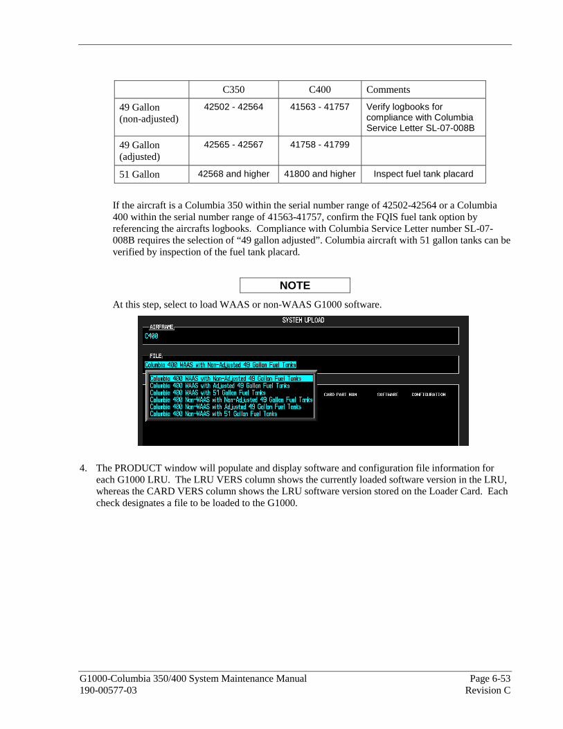
G1000-Columbia 350/400 System Maintenance Manual Page 6-53 190-00577-03 Revision C
C350 C400 Comments
49 Gallon (non-adjusted)
42502 - 42564 41563 - 41757 Verify logbooks for compliance with Columbia Service Letter SL-07-008B
49 Gallon (adjusted)
42565 - 42567 41758 - 41799
51 Gallon 42568 and higher 41800 and higher Inspect fuel tank placard
If the aircraft is a Columbia 350 within the serial number range of 42502-42564 or a Columbia 400 within the serial number range of 41563-41757, confirm the FQIS fuel tank option by referencing the aircrafts logbooks. Compliance with Columbia Service Letter number SL-07-008B requires the selection of “49 gallon adjusted”. Columbia aircraft with 51 gallon tanks can be verified by inspection of the fuel tank placard.
NOTE
At this step, select to load WAAS or non-WAAS G1000 software.
4. The PRODUCT window will populate and display software and configuration file information for each G1000 LRU. The LRU VERS column shows the currently loaded software version in the LRU, whereas the CARD VERS column shows the LRU software version stored on the Loader Card. Each check designates a file to be loaded to the G1000.

Page 6-54 G1000-Columbia 350/400 System Maintenance Manual Revision C 190-00577-03
By default, if an inequality between the LRU and CARD columns exists, the SOFTWARE CONFIGURATION boxes will be pre-selected (checked). By Default all of the CONFIGURATION boxes will be pre-selected.
The following softkeys provide an easy way to select files:
CHK ALL: Selects all files, both configuration and software
CHK SW: Selects all software files only.
CHK CFG: Selects all configuration files only.
CLR ALL: Clears all selections.
5. After verifying that the GDC software and configuration files are checked, press the LOAD softkey. It is acceptable to simply load the pre-selected software and config files. The G1000 system automatically begins loading software and default configuration files to the selected LRUs in the proper order.
6. When the system finishes loading, it prompts the technician accordingly. Press the ENT key to acknowledge that the upload is finished:
7. Verify that each column indicates in green when the loading process has finished and inspect the SUMMARY window as well to ensure that the load is successful.

G1000-Columbia 350/400 System Maintenance Manual Page 6-55 190-00577-03 Revision C
8. After the software and configuration files are loaded, turn off the system and reinsert the Supplemental Database Cards in the bottom slot of each display. Be sure to insert the card removed from the MFD back into the MFD
9. Continue to the GDC 74 Test procedure 6.6.4 GDC 74A Test
NOTE
Allow unit to warm up for 15 minutes before performing the following tests.
Altimeter & Pitot/Static Test
Verification of the altimeter and airspeed must be performed using a pitot/static ramp tester. The static port and altimeter must be verified in accordance with Title 14 of the Code of Federal Regulations (CFR) § 91.411 and Part 43 Appendix E, every two years. The PFD must be in Configuration mode and the MFD must be in Reversionary mode for performing the tests as outlined in Part 43 Appendix E.
To prepare the G1000 System for Part 43 Appendix E testing:
1. Start the G1000 system in normal mode.
2. Remove power to the PFD.
3. Turn the PFD on in Configuration mode by pressing and holding the ENT key on the PFD while applying power.
4. Release the ENT key after “INITIALIZING SYSTEM” appears in the upper left corner of the PFD.
CAUTION
Configuration mode contains certain pages and settings that are critical to aircraft operation and safety. These pages are protected and cannot be modified, unless the technician is properly authorized and equipped. However, most protected pages are viewable to allow system awareness for troubleshooting.
5. Using the outer FMS knob on the PFD turn to the GRS page group. Use the B ALT field for all CFR Part 43 Appendix E tests for G1000 altitude.
6. Place the MFD in Reversionary mode by pressing the red “display backup” button on the GMA 1347 Audio Panel. Baro settings can then be read from the MFD for the CFR Part 43 Appendix E tests.
After completing the tests specified by § 91.411 and Part 43 Appendix E, return the MFD to normal mode by pressing the red “display backup” button on the GMA 1347. Return the PFD to normal mode by shutting off the master switch. Upon restart the PFD will enter normal mode.
NOTE
The following tests are above and beyond the requirements set forth in Appendix E. Perform these tests every 2000 hours or 4 years, whichever comes first.

Page 6-56 G1000-Columbia 350/400 System Maintenance Manual Revision C 190-00577-03
Pitot/Static Airspeed Test
1. Command the pitot/static ramp tester to simulate air speeds shown in the table below.
2. Wait for the ramp tester to report that target values have been achieved.
3. Verify that computed air speeds shown on the PFD are within the tolerances specified in the table below:
Calibrated air speed, knots Allowed tolerance, ±knots 50 5.0 80 3.5
100 2.0 120 2.0 150 2.0
Static Port Vertical Speed (Rate of Climb) Test
1. Command ramp tester to change the altitude at the rates shown in the table below.
2. Wait for ramp tester to report that target rates have been achieved.
3. Verify that the Rate of Climb reported by the Vertical Speed field on the PFD is within the tolerances specified in the table below:
Vertical Speed, feet/minute Allowed tolerance, ±feet/minute 2000 100
0 45 -2000 100
OAT Probe Check
Check the outside air temperature (OAT) measurement shown on the PFD to ensure it reads ambient temperature.
If no other service is to be performed, continue to the return-to-service checks in Section 7.

G1000-Columbia 350/400 System Maintenance Manual Page 6-57 190-00577-03 Revision C
6.7 GRS 77 AHRS / GMU 44 Magnetometer Original GRS 77 is Reinstalled
If the original GRS 77 was reinstalled, then no software loading is required. This does not include units that were returned for repair as their software and configuration files are deleted during the repair testing process. Continue to the GRS/GMU Calibration section.
New or Repaired GRS 77 is Installed
If the GRS 77 was replaced with a new unit then software must be loaded. Continue to the GRS 77 Software Loading procedure.
Original GMU 44 is Reinstalled
If the original GMU 44 was reinstalled, then no software loading is required. This does not include units that were returned for repair as their software and configuration files are deleted during the repair testing process. Continue to the GRS/GMU Calibration section.
New or Repaired GMU 44 is Installed
If the GMU 44 was replaced with a new unit then software must be loaded. Continue to the GMU 44 Software Loading procedure.
6.7.1 GRS 77 Software Loading using GDU V6.XX
NOTE
The procedure in this section applies only to aircraft with GDU software version 6.XX. Procedures for G1000 systems with GDU version 8.XX follow this section.
1. Remove the Supplemental Database cards from the bottom slots of each display. Note which card was removed from the MFD so it may be identified later for reinsertion in the MFD when software and configuration loading is complete. It contains a FliteChart or ChartView database which is only used by the MFD.
2. Insert the correct G1000-Columbia 350/400 Code Loader Card (see Required Equipment List) into the top slot of the PFD.
3. Start the G1000 system in Configuration mode.
4. On the PFD, go to the Software Upload page using the FMS knob.
5. Highlight the GRS software file. Ensure that the GRS to GIA data path appears in the LRU field as shown:
6. Press the LOAD softkey.
7. Select OK and press the ENT key to acknowledge the following prompt:

Page 6-58 G1000-Columbia 350/400 System Maintenance Manual Revision C 190-00577-03
8. The software for the GRS 77 AHRS begins to load. Monitor the upload status as it progresses:
9. After the files finish loading, press the ENT key to acknowledge the following prompt:
10. Check the SUMMARY field to ensure the load is ‘COMPLETE’.
11. Go to the System Status page.
12. Activate the cursor and highlight ‘GRS1 – GIA1’, and then ‘GRS1 FPGA’ in the LRU window.
13. Verify that the reported part numbers and versions of the software files match the data in the Required Equipment List.
14. After the software and configuration files are loaded, turn off the system and reinsert the Supplemental Database Cards in the bottom slot of each display. Be sure to insert the card removed from the MFD back into the MFD.
15. Continue to the GRS/GMU Calibration section.
6.7.2 GMU 44 Software Loading using GDU V6.XX
NOTE
The procedure in this section applies only to aircraft with GDU software version 6.XX. Procedures for G1000 systems with GDU version 8.XX follow this section.
1. Remove the Supplemental Database cards from the bottom slots of each display. Note which card was removed from the MFD so it may be identified later for reinsertion in the MFD when software and configuration loading is complete. It contains a FliteChart or ChartView database which is only used by the MFD.
2. Insert the correct G1000-Columbia 350/400 Code Loader Card (see Required Equipment List) into the top slot of the PFD.
3. Start the G1000 system in Configuration mode.
4. On the PFD, go to the Software Upload page using the FMS knob.
5. Highlight the GMU software file. Ensure that GMU1 appears in the LRU field as shown:

G1000-Columbia 350/400 System Maintenance Manual Page 6-59 190-00577-03 Revision C
6. Press the LOAD softkey.
7. Select OK and press the ENT key to acknowledge the following prompt:
8. The software for the GMU 44 Magnetometer begins to load. Monitor the upload status as it
progresses:
9. After the files finish loading, press the ENT key to acknowledge the following prompt:
10. Check the SUMMARY field to ensure the load is ‘COMPLETE’.
11. Go to the System Status page.
12. Activate the cursor and highlight ‘GMU1’, then ‘GMU1 FPGA’ in the LRU window.
13. Verify that the reported part number and version of the software files match the data in the Required Equipment List.
14. After the software and configuration files are loaded, turn off the system and reinsert the Supplemental Database Cards in the bottom slot of each display. Be sure to insert the card removed from the MFD back into the MFD.
15. Continue to the GRS/GMU Calibration section.

Page 6-60 G1000-Columbia 350/400 System Maintenance Manual Revision C 190-00577-03
6.7.3 GRS 77 / GMU 44 Software Load and Configuration using GDU V8.XX
NOTE
The procedure in this section applies only to aircraft with GDU software version 8.XX. Procedures for G1000 systems with GDU version 6.XX precede this section.
1. On the PFD, go to the System Upload page using the small FMS knob.
2. Activate the cursor and use the small FMS knob to highlight the airframe type in the AIRFRAME field. Select the appropriate aircraft type (C400 or C350) and press the ENT key.
NOTE
Ensure that the correct airframe type is selected before proceeding; otherwise, incorrect configuration information will be loaded.
3. Once an airframe type is selected the cursor moves to the FILE window. Rotate the small FMS knob to activate the drop-down menu. Three FQIS fuel tank options are available: 49 gallon (non-adjusted); 49 gallon (adjusted); 51 gallon. Confirm the serial number of the aircraft prior to selection as well as inspect logbooks for field upgrades according to the following table.
C350 C400 Comments
49 Gallon (non-adjusted)
42502 - 42564 41563 - 41757 Verify logbooks for compliance with Columbia Service Letter SL-07-008B
49 Gallon (adjusted)
42565 - 42567 41758 - 41799
51 Gallon 42568 and higher 41800 and higher Inspect fuel tank placard
If the aircraft is a Columbia 350 within the serial number range of 42502-42564 or a Columbia 400 within the serial number range of 41563-41757, confirm the FQIS fuel tank option by referencing the aircrafts logbooks. Compliance with Columbia Service Letter number SL-07-008B requires the selection of “49 gallon adjusted”. Columbia aircraft with 51 gallon tanks can be verified by inspection of the fuel tank placard.

G1000-Columbia 350/400 System Maintenance Manual Page 6-61 190-00577-03 Revision C
NOTE
At this step, select to load WAAS or non-WAAS G1000 software.
4. The PRODUCT window will populate and display software and configuration file information for each G1000 LRU. The LRU VERS column shows the currently loaded software version in the LRU, whereas the CARD VERS column shows the LRU software version stored on the Loader Card. Each check designates a file to be loaded to the G1000.

Page 6-62 G1000-Columbia 350/400 System Maintenance Manual Revision C 190-00577-03
By default, if an inequality between the LRU and CARD columns exists, the SOFTWARE CONFIGURATION boxes will be pre-selected (checked). By default all of the CONFIGURATION boxes will be pre-selected.
The following softkeys provide an easy way to select files:
CHK ALL: Selects all files, both configuration and software
CHK SW: Selects all software files only.
CHK CFG: Selects all configuration files only.
CLR ALL: Clears all selections.
5. After verifying that the GRS/GMU software and configuration files are checked, press the LOAD softkey. It is acceptable to simply load the pre-selected software and config files. The G1000 system automatically begins loading software and default configuration files to the selected LRUs in the proper order.
6. When the system finishes loading, it prompts the technician accordingly. Press the ENT key to acknowledge that the upload is finished:
7. Verify that each column indicates in green when the loading process has finished and inspect the SUMMARY window as well to ensure that the load is successful.
8. After the software and configuration files are loaded, turn off the system and reinsert the Supplemental Database Cards in the bottom slot of each display. Be sure to insert the card removed from the MFD back into the MFD.
9. Continue to the GRS/GMU calibration procedure.
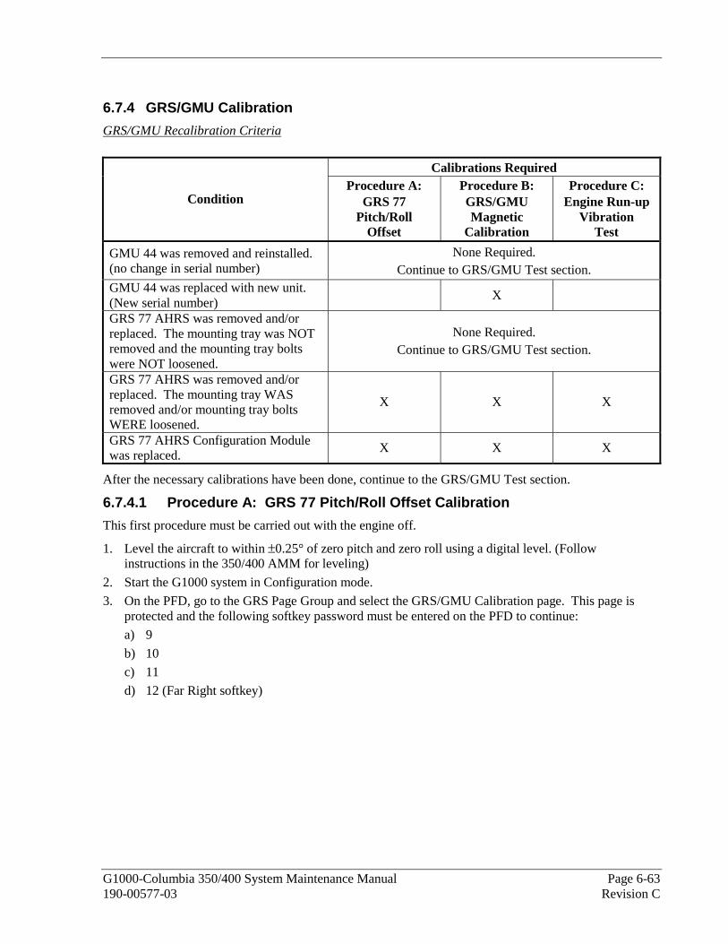
G1000-Columbia 350/400 System Maintenance Manual Page 6-63 190-00577-03 Revision C
6.7.4 GRS/GMU Calibration
GRS/GMU Recalibration Criteria
Calibrations Required
Condition Procedure A:
GRS 77 Pitch/Roll
Offset
Procedure B: GRS/GMU Magnetic
Calibration
Procedure C: Engine Run-up
Vibration Test
GMU 44 was removed and reinstalled. (no change in serial number)
None Required. Continue to GRS/GMU Test section.
GMU 44 was replaced with new unit. (New serial number)
X
GRS 77 AHRS was removed and/or replaced. The mounting tray was NOT removed and the mounting tray bolts were NOT loosened.
None Required. Continue to GRS/GMU Test section.
GRS 77 AHRS was removed and/or replaced. The mounting tray WAS removed and/or mounting tray bolts WERE loosened.
X X X
GRS 77 AHRS Configuration Module was replaced.
X X X
After the necessary calibrations have been done, continue to the GRS/GMU Test section.
6.7.4.1 Procedure A: GRS 77 Pitch/Roll Offset Calibration
This first procedure must be carried out with the engine off.
1. Level the aircraft to within ±0.25° of zero pitch and zero roll using a digital level. (Follow instructions in the 350/400 AMM for leveling)
2. Start the G1000 system in Configuration mode.
3. On the PFD, go to the GRS Page Group and select the GRS/GMU Calibration page. This page is protected and the following softkey password must be entered on the PFD to continue:
a) 9
b) 10
c) 11
d) 12 (Far Right softkey)

Page 6-64 G1000-Columbia 350/400 System Maintenance Manual Revision C 190-00577-03
4. Ensure that the No. 1 GRS 77 is selected in the SELECT GRS UNIT window on the PFD.
a) Activate the cursor and highlight the SELECT PROCEDURE window and select PITCH/ROLL OFFSET.
b) Press the ENT key.
c) Use the cursor to highlight the BEFORE CALIBRATION window.
d) Follow the checklist items displayed on the PFD and press the ENT key as each step is completed or confirmed.
e) When the CALIBRATE field is blinking, press the ENT button to begin the procedure.
f) After several seconds, a new checklist appears in the lower half of the PFD. Press the ENT key as each step is confirmed. When the CONFIRM AIRCRAFT IS LEVEL field is blinking, press the ENT key to continue.
5. The result of the pitch/roll offset compensation is displayed on the PFD. If successful, the AHRS records the required pitch and roll offsets, informs the operator of a successful conclusion and returns to normal operation.
6. Press the ENT key on the PFD to conclude this procedure.
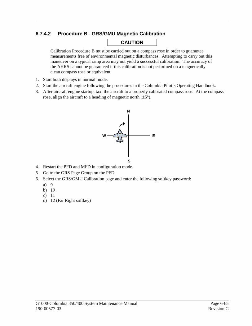
G1000-Columbia 350/400 System Maintenance Manual Page 6-65 190-00577-03 Revision C
6.7.4.2 Procedure B - GRS/GMU Magnetic Calibration
CAUTION
Calibration Procedure B must be carried out on a compass rose in order to guarantee measurements free of environmental magnetic disturbances. Attempting to carry out this maneuver on a typical ramp area may not yield a successful calibration. The accuracy of the AHRS cannot be guaranteed if this calibration is not performed on a magnetically clean compass rose or equivalent.
1. Start both displays in normal mode. 2. Start the aircraft engine following the procedures in the Columbia Pilot’s Operating Handbook. 3. After aircraft engine startup, taxi the aircraft to a properly calibrated compass rose. At the compass
rose, align the aircraft to a heading of magnetic north (±5°).
4. Restart the PFD and MFD in configuration mode. 5. Go to the GRS Page Group on the PFD. 6. Select the GRS/GMU Calibration page and enter the following softkey password:
a) 9 b) 10 c) 11 d) 12 (Far Right softkey)
N
S
EW
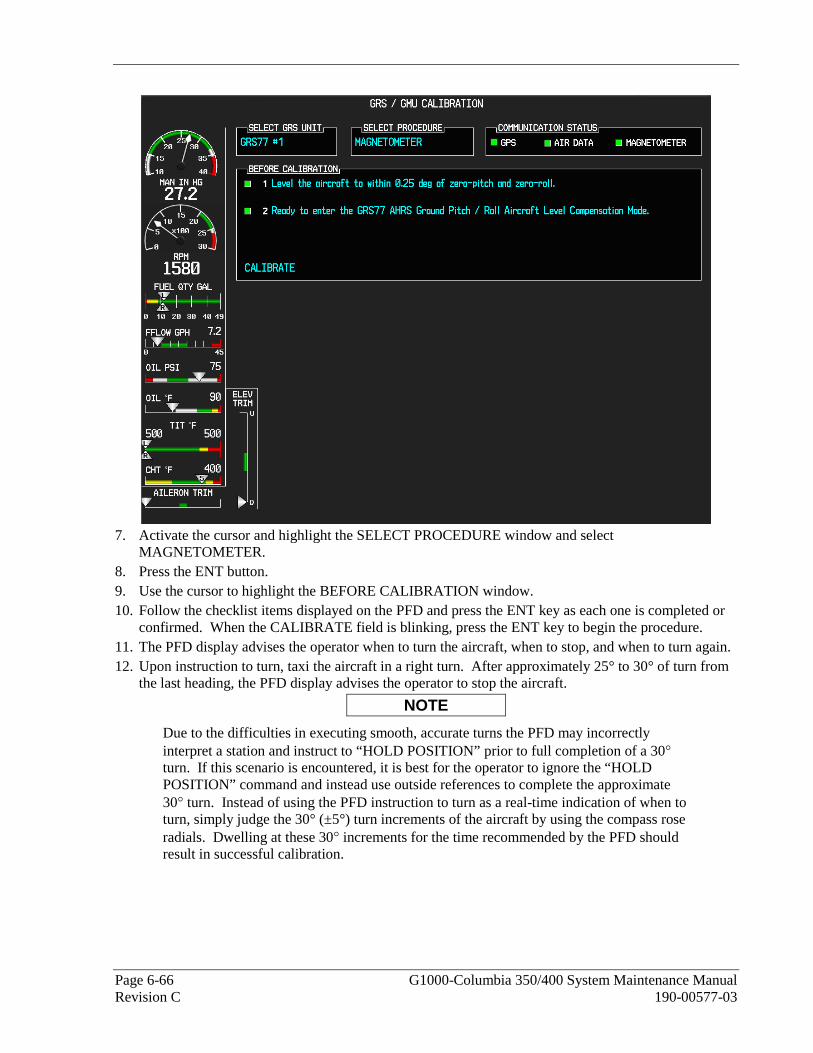
Page 6-66 G1000-Columbia 350/400 System Maintenance Manual Revision C 190-00577-03
7. Activate the cursor and highlight the SELECT PROCEDURE window and select
MAGNETOMETER. 8. Press the ENT button. 9. Use the cursor to highlight the BEFORE CALIBRATION window. 10. Follow the checklist items displayed on the PFD and press the ENT key as each one is completed or
confirmed. When the CALIBRATE field is blinking, press the ENT key to begin the procedure. 11. The PFD display advises the operator when to turn the aircraft, when to stop, and when to turn again. 12. Upon instruction to turn, taxi the aircraft in a right turn. After approximately 25° to 30° of turn from
the last heading, the PFD display advises the operator to stop the aircraft.
NOTE
Due to the difficulties in executing smooth, accurate turns the PFD may incorrectly interpret a station and instruct to “HOLD POSITION” prior to full completion of a 30° turn. If this scenario is encountered, it is best for the operator to ignore the “HOLD POSITION” command and instead use outside references to complete the approximate 30° turn. Instead of using the PFD instruction to turn as a real-time indication of when to turn, simply judge the 30° (±5°) turn increments of the aircraft by using the compass rose radials. Dwelling at these 30° increments for the time recommended by the PFD should result in successful calibration.

G1000-Columbia 350/400 System Maintenance Manual Page 6-67 190-00577-03 Revision C
13. The PFD guides the operator to dwell at multiple headings around a complete circle.
NOTE
Due to high winds or excessive airframe vibration, the operator may encounter a condition where the PFD restarts the 18-second countdown without full completion of the previous countdown. If this is encountered more than once for a given station, the operator should begin turning to the next station (approximately 30°). A minimum of 2 successful stations per quadrant is required, where a successful station is a full 18-second countdown followed by instruction to move. Ensure that at least 2 stations per quadrant are completed. Thus, it may sometimes be required to dwell at a station after a countdown restart. A maximum of 20 stations is allowed for the entire calibration procedure. If too many countdown restarts are encountered, the calibration will fail with the message, “TOO MANY STATIONS.”
14. Repeat the turn-and-stop process until the PFD advises that a successful calibration is complete. The GRS 77 AHRS then enters its normal operational mode. Press the ENT button on the PFD to conclude this procedure.

Page 6-68 G1000-Columbia 350/400 System Maintenance Manual Revision C 190-00577-03
6.7.4.3 Procedure C: Engine Run-Up Vibration Procedure
Calibration procedures A and B are not required prior to this procedure.
1. Start both displays in normal mode.
2. Start the aircraft engine following the procedures in the G1000/350/400 Airplane Flight Manual Supplement.
3. After aircraft engine startup, taxi the aircraft to a suitable area for engine run-up.
4. Restart both displays in configuration mode.
5. On the MFD, select the GEA page group. On the Engine Data page, monitor engine performance during the procedure.
6. Go to the GRS Page Group on the PFD.
7. Select the GRS/GMU Calibration page and enter the following softkey password:
a) 9 b) 10 c) 11 d) 12 (Far Right softkey)
8. Initiate the AHRS engine run-up vibration test procedure by performing the following steps:
a) Select the ENGINE RUN-UP TEST procedure and press the ENT key.
b) Follow the checklist items displayed on the PFD, and press the ENT key as each step is completed or confirmed.
c) When the CALIBRATE field is blinking, press the ENT key to begin the procedure.
9. The PFD instructs the operator to gradually increase power from idle to full throttle and back to idle over a period of 2-4 minutes.

G1000-Columbia 350/400 System Maintenance Manual Page 6-69 190-00577-03 Revision C
10. When the operator has completed the engine run-up and the engine is back to an idle setting, press the ENT key to indicate that the process is complete. When this is done, the TEST COMPLETE field stops blinking.
11. The PFD informs the operator if the installation has passed or failed the vibration test. If the test fails, the specific measurements causing the failure are identified and numeric values are displayed on the PFD.
12. Press the ENT button on the PFD to conclude this procedure.
NOTE
If failures are indicated, the engine run-up test may be repeated once or at most twice. If the test does not pass after three attempts, then the installation should not be considered reliable until the source of the vibration problem is identified and remedied. In the event of repeated failure of the engine run-up test, record the values that are reported to be out of range for future reference.
The following are potential causes for failure of the engine run-up test:
a) Vibration motion of GRS 77 and/or GMU 44 caused by neighboring equipment and/or supports.
b) Mounting screws and other hardware for GRS 77 and/or GMU 44 not firmly attached.
c) GRS 77 connector not firmly attached to unit.
d) Cabling leading to GRS 77 or GMU 44 not firmly secured to supporting structure.
e) An engine / propeller that is significantly out of balance

Page 6-70 G1000-Columbia 350/400 System Maintenance Manual Revision C 190-00577-03
6.7.4.4 Magnetometer Interference Test
Figure 6-7. Magnetometer Interference Test
1. Initiate the AHRS engine run-up vibration test procedure by performing the following steps:
a) Select the MAG INTERFERENCE TEST procedure and press the ENT key.
b) Follow the checklist items displayed on the PFD, and press the ENT key as each one is completed or confirmed. When the CALIBRATE field is blinking, press the ENT key to begin the procedure (as soon as the ENT key is pressed this time, a CALIBRATION PROCEDURE window will appear).
Figure 6-8. Magnetometer Interference Test Complete

G1000-Columbia 350/400 System Maintenance Manual Page 6-71 190-00577-03 Revision C
2. Leave the Navigation lights on for approximately 10 seconds, and then turn them off.
3. Wait approximately five seconds and then press the ENT key to complete the test.
4. The PFD informs the operator if the installation has passed or failed the magnetometer interference test. If the test passes, no further action is required.
5. Press the ENT key on the PFD to conclude this procedure.
6. If the MAG INTERFERENCE TEST fails but ALL of the deviations are less than the following thresholds (X < 5 mGauss, Y < 5mGauss, and Z < 8 mGauss), the installation must be verified with a flight test before it is acceptable.
NOTE
If failures are indicated, the magnetometer interference test may be repeated at most twice. If the test shows an X or Y deviation greater than or equal to 6 mGauss, or a Z deviation greater than or equal to 10 mGauss after three attempts, then the installation should not be considered reliable until the source of the interference problem is identified and remedied. In the event of repeated failure of the magnetometer interference test, record the values that are reported to be greater than or equal to 6 mGauss for future reference.
6.7.5 GRS/GMU Test
The aircraft can now be taxied back and the engine can be shut down for final checkout.
When the PFD powers up in normal mode, the AHRS attitude and heading information displayed should become valid within 1 minute of power-up. This confirms that the GRS 77 and GMU 44 work correctly.
If no other service is to be performed, continue to the return-to-service checks in Section 7.
6.7.6 GRS 77 Earth Magnetic Field Updates
The GRS 77 utilizes an Earth magnetic field model which is updated once every five years. The update is expected to be available from Garmin in each of the following years: 2010, 2015 and every five years thereafter, so long as the GRS 77 remains a Garmin-supported product.
The G1000 system alerts the operator that the magnetic field database is out of date by issuing the message “AHRS SERVICE – AHRS Magnetic-field model needs update” (Reference Section Common Alerts 4.9.3). Contact Garmin for update instructions.

Page 6-72 G1000-Columbia 350/400 System Maintenance Manual Revision C 190-00577-03
6.8 GDL 69A Data Link Original GDL 69A is Reinstalled
No software or configuration loading is required if the removed GDL 69A is re-installed. This does not include units that were returned for repair as their software and configuration files are deleted during the repair testing process. Continue to the GDL 69A Test procedure.
New GDL 69A is Installed
If a new GDL 69A is installed, the correct software and configuration files must be loaded to the unit. The GDL 69A will also have to be activated. Continue to the GDL 69A Software Loading procedure.
6.8.1 GDL 69A Software Loading using GDU V6.XX
NOTE
The procedure in this section applies only to aircraft with GDU software version 6.XX. Procedures for G1000 systems with GDU version 8.XX follow this section
1. Remove the Supplemental Database cards from the bottom slots of each display. Note which card was removed from the MFD so it may be identified later for reinsertion in the MFD when software and configuration loading is complete. It contains a FliteChart or ChartView database which is only used by the MFD.
2. Insert the correct G1000-Columbia 350/400 Code Loader Card (see Required Equipment List) into the top slot of the PFD.
3. Start the G1000 system in Configuration mode.
4. On the PFD, go to the Software Upload page using the FMS knob.
5. Highlight the GDL software file. Ensure that GDL69 appears in the LRU field as shown:
6. Press the LOAD softkey.
7. Select OK and press the ENT key to acknowledge the following prompt:
8. The software for the GDL 69A data link begins to load. Monitor the upload status as it progresses:
9. After the files finish loading, press ENT to acknowledge the following prompt:

G1000-Columbia 350/400 System Maintenance Manual Page 6-73 190-00577-03 Revision C
10. Check the SUMMARY field to ensure the load is ‘COMPLETE’.
11. Deactivate the cursor.
12. Go to the System Status page.
13. Activate the cursor and highlight ‘GDL69’ in the LRU window.
14. Verify that the reported part number and version of the software matches the data in the Required Equipment List.
15. Continue to the GDL 69A Configuration procedure.
6.8.2 GDL 69A Configuration Loading using GDU V6.XX
NOTE
The procedure in this section applies only to aircraft with GDU software version 6.XX. Procedures for G1000 systems with GDU version 8.XX follow this section
1. Insert the correct G1000-Columbia 350/400 Code Loader Card (see Required Equipment List) into the top slot of the PFD.
2. Start the G1000 system in Configuration mode.
3. On the PFD, go to the Configuration Upload page using the FMS knob:
4. Activate the cursor and use the small FMS knob to highlight the airframe type in the FILE field.
NOTE
Ensure that the correct airframe type is selected before proceeding; otherwise, incorrect configuration information will be loaded.
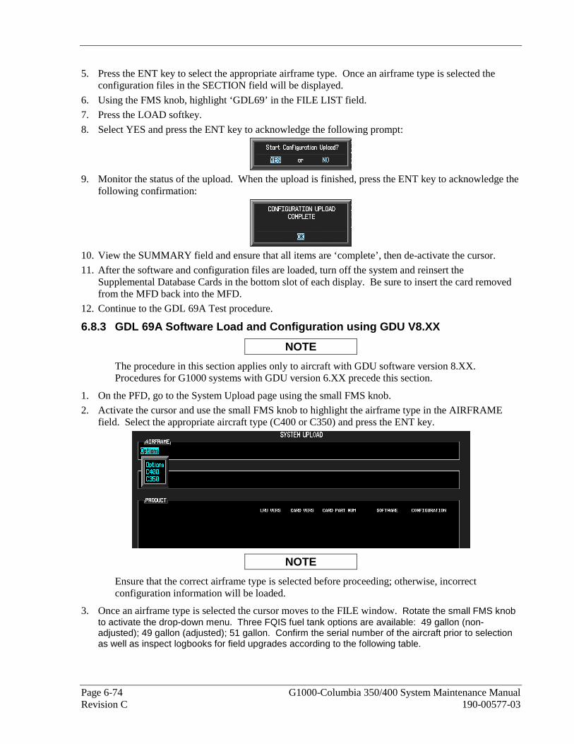
Page 6-74 G1000-Columbia 350/400 System Maintenance Manual Revision C 190-00577-03
5. Press the ENT key to select the appropriate airframe type. Once an airframe type is selected the configuration files in the SECTION field will be displayed.
6. Using the FMS knob, highlight ‘GDL69’ in the FILE LIST field.
7. Press the LOAD softkey.
8. Select YES and press the ENT key to acknowledge the following prompt:
9. Monitor the status of the upload. When the upload is finished, press the ENT key to acknowledge the
following confirmation:
10. View the SUMMARY field and ensure that all items are ‘complete’, then de-activate the cursor.
11. After the software and configuration files are loaded, turn off the system and reinsert the Supplemental Database Cards in the bottom slot of each display. Be sure to insert the card removed from the MFD back into the MFD.
12. Continue to the GDL 69A Test procedure.
6.8.3 GDL 69A Software Load and Configuration using GDU V8.XX
NOTE
The procedure in this section applies only to aircraft with GDU software version 8.XX. Procedures for G1000 systems with GDU version 6.XX precede this section.
1. On the PFD, go to the System Upload page using the small FMS knob.
2. Activate the cursor and use the small FMS knob to highlight the airframe type in the AIRFRAME field. Select the appropriate aircraft type (C400 or C350) and press the ENT key.
NOTE
Ensure that the correct airframe type is selected before proceeding; otherwise, incorrect configuration information will be loaded.
3. Once an airframe type is selected the cursor moves to the FILE window. Rotate the small FMS knob to activate the drop-down menu. Three FQIS fuel tank options are available: 49 gallon (non-adjusted); 49 gallon (adjusted); 51 gallon. Confirm the serial number of the aircraft prior to selection as well as inspect logbooks for field upgrades according to the following table.

G1000-Columbia 350/400 System Maintenance Manual Page 6-75 190-00577-03 Revision C
C350 C400 Comments
49 Gallon (non-adjusted)
42502 - 42564 41563 - 41757 Verify logbooks for compliance with Columbia Service Letter SL-07-008B
49 Gallon (adjusted)
42565 - 42567 41758 - 41799
51 Gallon 42568 and higher 41800 and higher Inspect fuel tank placard
If the aircraft is a Columbia 350 within the serial number range of 42502-42564 or a Columbia 400 within the serial number range of 41563-41757, confirm the FQIS fuel tank option by referencing the aircrafts logbooks. Compliance with Columbia Service Letter number SL-07-008B requires the selection of “49 gallon adjusted”. Columbia aircraft with 51 gallon tanks can be verified by inspection of the fuel tank placard.
NOTE
At this step, select to load WAAS or non-WAAS G1000 software.
4. The PRODUCT window will populate and display software and configuration file information for each G1000 LRU. The LRU VERS column shows the currently loaded software version in the LRU, whereas the CARD VERS column shows the LRU software version stored on the Loader Card. Each check designates a file to be loaded to the G1000.

Page 6-76 G1000-Columbia 350/400 System Maintenance Manual Revision C 190-00577-03
By default, if an inequality between the LRU and CARD columns exists, the SOFTWARE CONFIGURATION boxes will be pre-selected (checked). By default all of the CONFIGURATION boxes will be pre-selected.
The following softkeys provide an easy way to select files:
CHK ALL: Selects all files, both configuration and software
CHK SW: Selects all software files only.
CHK CFG: Selects all configuration files only.
CLR ALL: Clears all selections.
5. After verifying that the GDL software and configuration files are checked, press the LOAD softkey. It is acceptable to simply load the pre-selected software and config files. The G1000 system automatically begins loading software and default configuration files to the selected LRUs in the proper order.
6. When the system finishes loading, it prompts the technician accordingly. Press the ENT key to acknowledge that the upload is finished:
7. Verify that each column indicates in green when the loading process has finished and inspect the SUMMARY window as well to ensure that the load is successful.

G1000-Columbia 350/400 System Maintenance Manual Page 6-77 190-00577-03 Revision C
8. After the software and configuration files are loaded, turn off the system and reinsert the Supplemental Database Cards in the bottom slot of each display. Be sure to insert the card removed from the MFD back into the MFD.
9. Continue to the GDL 69 Test procedure. 6.8.4 GDL 69A Test
NOTE
This section verifies correct installation in the aircraft. It does not activate the GDL 69 XM data link radio. If the XM Radio is activated, the channel list will contain more channels than the three that are shown for a radio that has not been activated. Complete instructions for activating the XM data link can be found in Garmin document 190-00355-04.
1. Select the AUX – XM RADIO page on the MFD.
2. Using the channel control located in the cabin, verify that you can increment and decrement the channels (the white arrow to the left of the channel list indicates the currently selected channel). Select channel 1 when complete.
3. Using the volume control located in the cabin, verify that you can increase and decrease the XM radio volume (the volume bar at the bottom of the screen will show changes to the volume level). Set the volume to the mid position when done.
4. Plug a set of headphones into one of the passenger stations and verify that you can hear the XM radio playing in both left and right channels. The volume level may be adjusted to a comfortable level at this point.
5. Plug a set of headphones into one of the pilot station and verify that you can hear the XM radio playing in both left and right channels.

Page 6-78 G1000-Columbia 350/400 System Maintenance Manual Revision C 190-00577-03
6.9 GSA 81 Autopilot Servos/GTA 82 Pitch Trim Adapter Original GSA 81/GTA 82 is Reinstalled
No software is required if the removed GSA 81/GTA 82 is re-installed. This does not include units that were returned for repair as their software and configuration files are deleted during the repair testing process. Continue to the GFC 700 Autopilot Ground Checks in Section 6.10.
New GSA 81/GTA 82 is Installed
If a new GSA 81/GTA 82 is installed, the correct software and certification gains must be loaded to the unit. Continue to the GSA 81 or GTA 82 Software Loading procedure, as appropriate. After software is loaded, load certification gains into affected unit according to Section 15 and then complete the GFC 700 Autopilot Ground Checks in Section 6.106.10
6.9.1 GSA 81 Servo Software Loading using GDU V6.XX
NOTE
The procedure in this section applies only to aircraft with GDU software version 6.XX. Procedures for G1000 systems with GDU version 8.XX follow this section.
1. Remove the Supplemental Database cards from the bottom slots of each display. Note which card was removed from the MFD so it may be identified later for reinsertion in the MFD when software and configuration loading is complete. It contains a FliteChart or ChartView database which is only used by the MFD.
2. Insert the G1000-Columbia 350/400 Code Loader Card (see Required Equipment List) into the top slot of the PFD.
3. Start the G1000 system in Configuration mode.
4. On the PFD, go to the Configuration Upload page using the FMS knob:
5. Highlight the GSA 8X software file. Ensure that each GSA to GIA data path appears in the LRU
field as shown. Each servo axis is identified by the letters ‘P’ for pitch and ‘R’ for roll. Each servo consists of a monitor, denoted by the letter ‘M’, and a controller, denoted by the letter ‘C’. Each servo interfaces to GIA1 and GIA2. The current software version is noted next to each LRU.
6. Press the LRU softkey to toggle the cursor to the LRU window.
7. Use the FMS knob to select the LRU to load and press the LOAD softkey.
8. Verify YES and press the ENT key to acknowledge the following prompt:

G1000-Columbia 350/400 System Maintenance Manual Page 6-79 190-00577-03 Revision C
9. The software for the GSA 81 servo begins to load. Monitor the upload status as it progresses:
10. After the files finish loading, press the ENT key to acknowledge the following prompt:
11. Check the SUMMARY field to ensure the load is ‘COMPLETE’.
12. Highlight both the monitor (M) and controller (C) for each servo that was replaced and repeat Steps 5 through 10. The servo-to-GIA2 paths should not be loaded, since these are just redundant paths (loading via the GIA2 paths will simply reload the GSA software).
13. Deactivate the cursor.
14. Go to the System Status page.
15. Activate the cursor and highlight ‘GSA x C – GIA1’, then highlight ‘GSA x M – GIA1’ in the LRU window, where x is P or R for the pitch or roll servo as appropriate.
16. Verify that the reported part number and version of the software files matches the data in the Required Equipment List.
17. After the software and configuration files are loaded, turn off the system and reinsert the Supplemental Database Cards in the bottom slot of each display. Be sure to insert the card removed from the MFD back into the MFD.

Page 6-80 G1000-Columbia 350/400 System Maintenance Manual Revision C 190-00577-03
6.9.2 GTA 82 Pitch Trim Adapter Software Loading using GDU V6.XX
NOTE
The procedure in this section applies only to aircraft with GDU software version 6.XX. Procedures for G1000 systems with GDU version 8.XX follow this section.
1. Remove the Supplemental Database cards from the bottom slots of each display. Note which card was removed from the MFD so it may be identified later for reinsertion in the MFD when software and configuration loading is complete. It contains a FliteChart or ChartView database which is only used by the MFD.
2. Insert the correct G1000-Columbia 350/400 Code Loader Card (see Required Equipment List) into the top slot of the PFD.
3. Start the G1000 system in Configuration mode.
4. On the PFD, go to the Configuration Upload page using the FMS knob:
5. Highlight the GTA 82 software file. Ensure that both paths to the GTA 82 through GIA1 and GIA2 appear in the LRU field as shown:
6. Press the LRU softkey. Select the GTA - GIA1 data path to load software. Press the LOAD softkey.
7. Select OK and press the ENT key to acknowledge the following prompt:
8. The software for the GTA 82 begins to load. Monitor the upload status as it progresses:
9. After the files finish loading, press ENT to acknowledge the following prompt:
10. Check the SUMMARY field to ensure the all software loads are ‘COMPLETE’.
11. De-activate the cursor.

G1000-Columbia 350/400 System Maintenance Manual Page 6-81 190-00577-03 Revision C
12. Go to the System Status page.
13. Activate the cursor and highlight ‘GTA PT – GIA1’ in the LRU window.
14. Verify that the reported part number and version of the software file matches the data in the Required Equipment List.
15. After the software and configuration files are loaded, turn off the system and reinsert the Supplemental Database Cards in the bottom slot of each display. Be sure to insert the card removed from the MFD back into the MFD.

Page 6-82 G1000-Columbia 350/400 System Maintenance Manual Revision C 190-00577-03
6.9.3 GIA 63, GSA 81 and GTA 82 Certification Gain Loading using GDU V6.XX
NOTE
The procedure in this section applies only to aircraft with GDU software version 6.XX. Procedures for G1000 systems with GDU version 8.XX follow this section.
NOTE
There will be two GFC 700 files on the loader card. Selecting the 006-D0271-00 file will cause items that have never been loaded before to appear in the LRU window. Selecting the second GFC 700 file will cause items that have been previously loaded to appear in the LRU window. Highlight the file that causes the appropriate item to appear in the LRU window and do not use the other file if its associated LRU window is empty.
1. Highlight the GFC700 Certification Gains software file. The following GFC1 CERT and GFC2 CERT paths may appear in the LRU field (a sample screen is shown below):
GFC1 CERT GIA ____ GFC2 CERT GIA ____
GFC1 CERT P C ____ GFC2 CERT P C ____ (not loaded)
GFC1 CERT P M ____ GFC2 CERT P M ____ (not loaded)
GFC1 CERT PT ____ GFC2 CERT PT ____ (not loaded)
GFC1 CERT R C ____ GFC2 CERT R C ____ (not loaded)
GFC1 CERT R M ____ GFC2 CERT R M ____ (not loaded)
2. Press the LRU softkey to toggle the cursor to the LRU window.
3. Use the FMS knob to select the LRU to be loaded. The pitch and roll servos each require two items to be loaded – monitor (M) and controller (C). The GIA and pitch trim adapter each only require that one item be loaded.
4. Press the LOAD softkey to start loading the selected item.
5. Select YES and press the ENT key to acknowledge the following prompt:
6. The GFC 700 certification software gains begin to load. Monitor the upload status as it progresses:
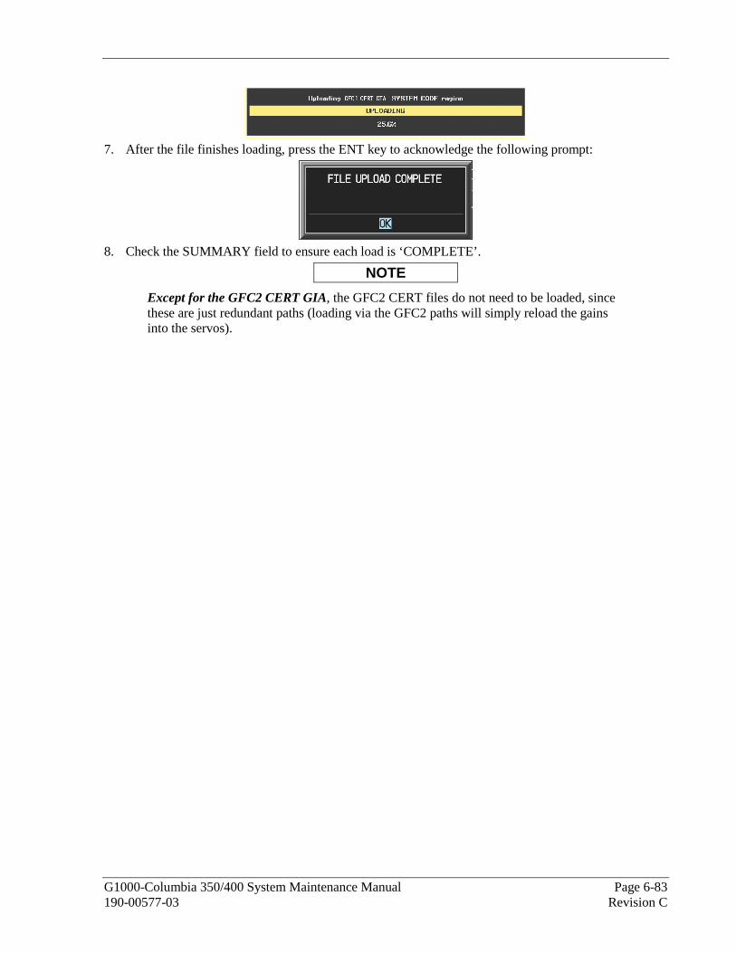
G1000-Columbia 350/400 System Maintenance Manual Page 6-83 190-00577-03 Revision C
7. After the file finishes loading, press the ENT key to acknowledge the following prompt:
8. Check the SUMMARY field to ensure each load is ‘COMPLETE’.
NOTE
Except for the GFC2 CERT GIA, the GFC2 CERT files do not need to be loaded, since these are just redundant paths (loading via the GFC2 paths will simply reload the gains into the servos).
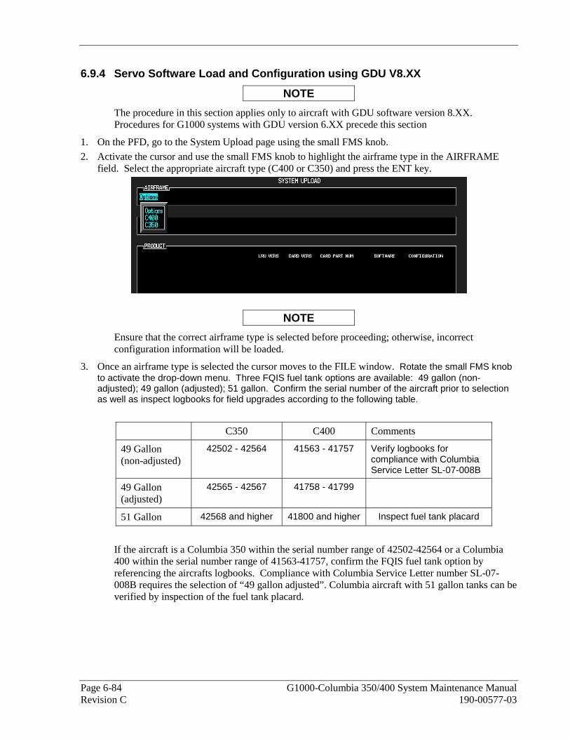
Page 6-84 G1000-Columbia 350/400 System Maintenance Manual Revision C 190-00577-03
6.9.4 Servo Software Load and Configuration using GDU V8.XX
NOTE
The procedure in this section applies only to aircraft with GDU software version 8.XX. Procedures for G1000 systems with GDU version 6.XX precede this section
1. On the PFD, go to the System Upload page using the small FMS knob.
2. Activate the cursor and use the small FMS knob to highlight the airframe type in the AIRFRAME field. Select the appropriate aircraft type (C400 or C350) and press the ENT key.
NOTE
Ensure that the correct airframe type is selected before proceeding; otherwise, incorrect configuration information will be loaded.
3. Once an airframe type is selected the cursor moves to the FILE window. Rotate the small FMS knob to activate the drop-down menu. Three FQIS fuel tank options are available: 49 gallon (non-adjusted); 49 gallon (adjusted); 51 gallon. Confirm the serial number of the aircraft prior to selection as well as inspect logbooks for field upgrades according to the following table.
C350 C400 Comments
49 Gallon (non-adjusted)
42502 - 42564 41563 - 41757 Verify logbooks for compliance with Columbia Service Letter SL-07-008B
49 Gallon (adjusted)
42565 - 42567 41758 - 41799
51 Gallon 42568 and higher 41800 and higher Inspect fuel tank placard
If the aircraft is a Columbia 350 within the serial number range of 42502-42564 or a Columbia 400 within the serial number range of 41563-41757, confirm the FQIS fuel tank option by referencing the aircrafts logbooks. Compliance with Columbia Service Letter number SL-07-008B requires the selection of “49 gallon adjusted”. Columbia aircraft with 51 gallon tanks can be verified by inspection of the fuel tank placard.

G1000-Columbia 350/400 System Maintenance Manual Page 6-85 190-00577-03 Revision C
NOTE
At this step, select to load WAAS or non-WAAS G1000 software.
4. The PRODUCT window will populate and display software and configuration file information for each G1000 LRU. The LRU VERS column shows the currently loaded software version in the LRU, whereas the CARD VERS column shows the LRU software version stored on the Loader Card. Each check designates a file to be loaded to the G1000.
By default, if an inequality between the LRU and CARD columns exists, the SOFTWARE CONFIGURATION boxes will be pre-selected (checked). By default all of the CONFIGURATION boxes will be pre-selected.

Page 6-86 G1000-Columbia 350/400 System Maintenance Manual Revision C 190-00577-03
The following softkeys provide an easy way to select files:
CHK ALL: Selects all files, both configuration and software
CHK SW: Selects all software files only.
CHK CFG: Selects all configuration files only.
CLR ALL: Clears all selections.
5. After verifying that the Servo/GTA/GIA software and configuration files are checked, press the LOAD softkey. It is acceptable to simply load the pre-selected software and config files. The G1000 system automatically begins loading software and default configuration files to the selected LRUs in the proper order.
6. When the system finishes loading, it prompts the technician accordingly. Press the ENT key to acknowledge that the upload is finished:
7. Verify that each column indicates in green when the loading process has finished and inspect the SUMMARY window as well to ensure that the load is successful.
8. After the software and configuration files are loaded, turn off the system and reinsert the Supplemental Database Cards in the bottom slot of each display. Be sure to insert the card removed from the MFD back into the MFD.
9. Continue to the GEA 71 Test procedure.
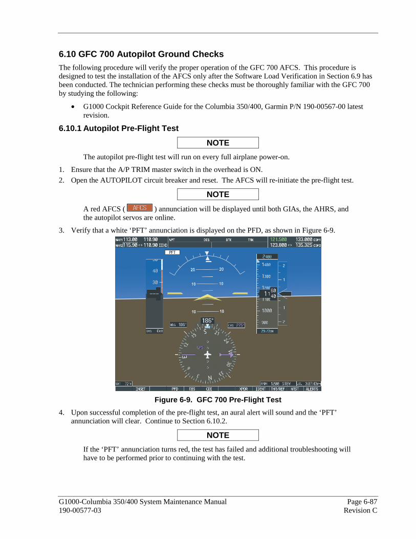
G1000-Columbia 350/400 System Maintenance Manual Page 6-87 190-00577-03 Revision C
6.10 GFC 700 Autopilot Ground Checks The following procedure will verify the proper operation of the GFC 700 AFCS. This procedure is designed to test the installation of the AFCS only after the Software Load Verification in Section 6.9 has been conducted. The technician performing these checks must be thoroughly familiar with the GFC 700 by studying the following:
• G1000 Cockpit Reference Guide for the Columbia 350/400, Garmin P/N 190-00567-00 latest revision.
6.10.1 Autopilot Pre-Flight Test
NOTE
The autopilot pre-flight test will run on every full airplane power-on.
1. Ensure that the A/P TRIM master switch in the overhead is ON.
2. Open the AUTOPILOT circuit breaker and reset. The AFCS will re-initiate the pre-flight test.
NOTE
A red AFCS ( ) annunciation will be displayed until both GIAs, the AHRS, and the autopilot servos are online.
3. Verify that a white ‘PFT’ annunciation is displayed on the PFD, as shown in Figure 6-9.
Figure 6-9. GFC 700 Pre-Flight Test
4. Upon successful completion of the pre-flight test, an aural alert will sound and the ‘PFT’ annunciation will clear. Continue to Section 6.10.2.
NOTE
If the ‘PFT’ annunciation turns red, the test has failed and additional troubleshooting will have to be performed prior to continuing with the test.

Page 6-88 G1000-Columbia 350/400 System Maintenance Manual Revision C 190-00577-03
5. If the aural alert is not heard, but pre-flight testing passed, engage the Autopilot by pressing the AP key on the MFD and disengage the Autopilot by pressing the AP key again. Visual and aural disconnect alerting should occur. If no alert is heard, the audio interface between GIA No. 1 and the audio panel should be checked. If an alert is heard, the audio interface between GIA No. 2 and the audio panel should be checked.
6.10.2 AFCS Switch Checks
To verify that the AFCS system buttons and switches are operating correctly, perform the following checks:
1. Actuate the manual electric trim (MET) hat switch forward/aft on the pilot’s control stick. The pitch trim should engage and the run in the selected direction. Check operation in both directions.
2. While actuating the pilot’s MET switch in the pitch axis, press the A/P DISC button on the pilot’s control stick and hold. The pitch trim should stop running and the pitch trim indication should stop moving. The pitch trim will not run for as long as the A/P DISC button is pressed.
3. Release the pilot’s A/P DISC button. The trim should resume running. Release the MET switch.
4. Actuate the MET switch forward/aft on the copilot’s control stick. The pitch trim should engage and the run in the selected direction. Check operation in both directions.
5. While actuating the copilot’s MET switch in the pitch axis, press the A/P DISC button on the copilot’s control stick and hold. The pitch trim should stop running and the pitch trim indication should stop moving. The pitch trim will not run for as long as the A/P DISC button is pressed.
6. Release the copilot’s A/P DISC button. The trim should resume running. Release the MET switch.
7. Engage the Autopilot by pressing the AP key on the MFD. The pitch and roll clutches should engage, resisting movement of the control stick.
8. Press and hold the CWS switch on the pilot’s control stick. CWS should be annunciated on the PFD and the control stick should now move freely when moved manually.
9. Release the CWS switch. CWS should be removed from the PFD and the autopilot should hold the control stick in its present attitude.
10. Press the A/P DISC switch. The Autopilot should command a normal disengagement. A single disconnect tone will be heard and a flashing amber “AP” will be visible on the PFD for approximately five seconds.
11. Verify that the control stick is free in pitch and roll axes.
12. Engage the Autopilot.
13. Pull the AUTOPILOT circuit breaker. The Autopilot should command an abnormal disconnect, consisting of a continuous disconnect tone and flashing red ‘AP’. No AFCS annunciations (e.g. AFCS, PFT, Mistrim) should remain on the PFD.
14. Press the AP key on the MFD to silence the autopilot abnormal disconnect tone and then reset the AUTOPILOT breaker.
15. Wait for the pre-flight test sequence to successfully complete again.
16. Press the Go Around button on the flap control panel. ‘GA’ should be annunciated on the PFD for both pitch and roll modes and the command bars should indicate a wings-level climb to 7 degrees.
NOTE
The GA ENGAGED legend on the Go Around button will not illuminate, since it is not supported in the current version of software.
17. Press the FD key on the MFD twice to deactivate the Go Around mode and reset the Flight Director. Green ‘PIT’ and ‘ROL’ annunciations will be visible on the PFD.
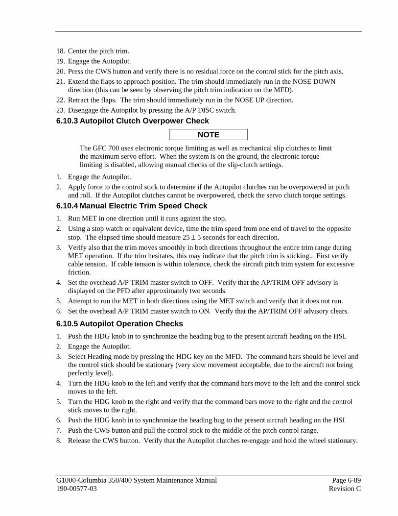
G1000-Columbia 350/400 System Maintenance Manual Page 6-89 190-00577-03 Revision C
18. Center the pitch trim.
19. Engage the Autopilot.
20. Press the CWS button and verify there is no residual force on the control stick for the pitch axis.
21. Extend the flaps to approach position. The trim should immediately run in the NOSE DOWN direction (this can be seen by observing the pitch trim indication on the MFD).
22. Retract the flaps. The trim should immediately run in the NOSE UP direction.
23. Disengage the Autopilot by pressing the A/P DISC switch.
6.10.3 Autopilot Clutch Overpower Check
NOTE
The GFC 700 uses electronic torque limiting as well as mechanical slip clutches to limit the maximum servo effort. When the system is on the ground, the electronic torque limiting is disabled, allowing manual checks of the slip-clutch settings.
1. Engage the Autopilot.
2. Apply force to the control stick to determine if the Autopilot clutches can be overpowered in pitch and roll. If the Autopilot clutches cannot be overpowered, check the servo clutch torque settings.
6.10.4 Manual Electric Trim Speed Check
1. Run MET in one direction until it runs against the stop.
2. Using a stop watch or equivalent device, time the trim speed from one end of travel to the opposite stop. The elapsed time should measure 25 ± 5 seconds for each direction.
3. Verify also that the trim moves smoothly in both directions throughout the entire trim range during MET operation. If the trim hesitates, this may indicate that the pitch trim is sticking.. First verify cable tension. If cable tension is within tolerance, check the aircraft pitch trim system for excessive friction.
4. Set the overhead A/P TRIM master switch to OFF. Verify that the AP/TRIM OFF advisory is displayed on the PFD after approximately two seconds.
5. Attempt to run the MET in both directions using the MET switch and verify that it does not run.
6. Set the overhead A/P TRIM master switch to ON. Verify that the AP/TRIM OFF advisory clears.
6.10.5 Autopilot Operation Checks
1. Push the HDG knob in to synchronize the heading bug to the present aircraft heading on the HSI.
2. Engage the Autopilot.
3. Select Heading mode by pressing the HDG key on the MFD. The command bars should be level and the control stick should be stationary (very slow movement acceptable, due to the aircraft not being perfectly level).
4. Turn the HDG knob to the left and verify that the command bars move to the left and the control stick moves to the left.
5. Turn the HDG knob to the right and verify that the command bars move to the right and the control stick moves to the right.
6. Push the HDG knob in to synchronize the heading bug to the present aircraft heading on the HSI
7. Push the CWS button and pull the control stick to the middle of the pitch control range.
8. Release the CWS button. Verify that the Autopilot clutches re-engage and hold the wheel stationary.

Page 6-90 G1000-Columbia 350/400 System Maintenance Manual Revision C 190-00577-03
9. Holding the control stick lightly, press the NOSE UP key on the MFD twice, to increase the pitch reference. Verify that the command bars move up approximately one degree and the control stick begins moving aft.
10. Hold the control stick and press the CWS button, re-synchronizing the pitch reference and re-centering the control stick.
11. Release the CWS button and verify that servo clutches re-engage before releasing the control stick.
12. Press the NOSE DN key on the MFD twice. Verify that the command bars command down and the control stick begins moving forward.
13. Hold the controls and press CWS to re-center the command bars and stop control stick movement.
14. With the Autopilot still engaged and the CWS button pressed, move the control stick to its aft limit.
15. Release the CWS button and apply continuous forward pressure, slowly moving the control stick. After 1 or 2 seconds, the trim should begin moving in a trim up direction.
16. Grip the control stick and press the CWS button. Trim motion should stop.
17. Move the control stick to the forward limit and release the CWS button.
18. Slowly pull back on the control stick. After a similar delay, the trim should begin to trim down.
19. Relieve pressure on the control stick and the trim motion should stop.
20. Hold the control stick and press the A/P DISC switch to disconnect the Autopilot.
21. Engage VS mode by pressing the VS key on the MFD. Verify the PFD displays ‘VS’ in green and indicates a pitch reference of ‘0 FPM’.
22. Press the FLC key on the MFD and verify that ‘FLC’ is annunciated on the PFD in green with a reference of 80 KTS (NOTE: This is the minimum speed reference for this airplane).
23. Press the ALT key on the MFD and verify that the ‘ALT’ annunciation is displayed in green on the PFD with an altitude reference equal to the aircraft altitude.
24. Press the FD key and verify that the mode annunciations and command bars are removed from the display.
6.10.6 Servo Torque Limit Validation
This procedure validates the servo torque limits by measuring the bridle cable tension under servo load. Prior to starting, verify tension on all GFC autopilot bridle cables (servo cable rigging tension) are within the limits specified by the following procedure:
6.10.6.1 Pitch Torque
1. Open the PFD and MFD circuit breakers.
2. Turn on power to the G1000 system.
3. While holding the ENT key on the PFD, close the PFD circuit breaker.
4. When INITIALIZING SYSTEM appears on the PFD, release the ENT key. The PFD will be in configuration mode.
5. Repeat steps 3 and 4 for the MFD.
6. Using the FMS knob, navigate to the GFC page group and select the second page in this page group. The title of this page is “GFC STATUS.”
7. Change the RPM to +2.50rpm as shown in Figure 6-10. and press the ENT key.
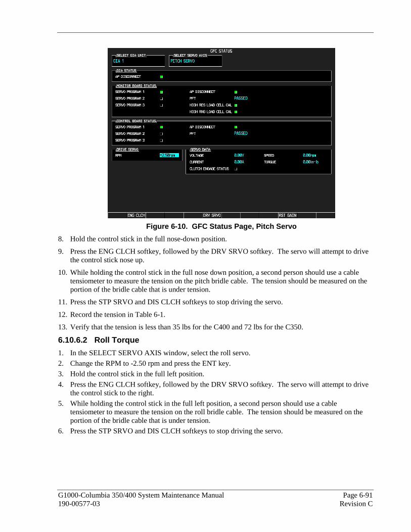
G1000-Columbia 350/400 System Maintenance Manual Page 6-91 190-00577-03 Revision C
Figure 6-10. GFC Status Page, Pitch Servo
8. Hold the control stick in the full nose-down position.
9. Press the ENG CLCH softkey, followed by the DRV SRVO softkey. The servo will attempt to drive the control stick nose up.
10. While holding the control stick in the full nose down position, a second person should use a cable tensiometer to measure the tension on the pitch bridle cable. The tension should be measured on the portion of the bridle cable that is under tension.
11. Press the STP SRVO and DIS CLCH softkeys to stop driving the servo.
12. Record the tension in Table 6-1.
13. Verify that the tension is less than 35 lbs for the C400 and 72 lbs for the C350.
6.10.6.2 Roll Torque
1. In the SELECT SERVO AXIS window, select the roll servo.
2. Change the RPM to -2.50 rpm and press the ENT key.
3. Hold the control stick in the full left position.
4. Press the ENG CLCH softkey, followed by the DRV SRVO softkey. The servo will attempt to drive the control stick to the right.
5. While holding the control stick in the full left position, a second person should use a cable tensiometer to measure the tension on the roll bridle cable. The tension should be measured on the portion of the bridle cable that is under tension.
6. Press the STP SRVO and DIS CLCH softkeys to stop driving the servo.

Page 6-92 G1000-Columbia 350/400 System Maintenance Manual Revision C 190-00577-03
7. Record the tension in Table 6-1.
8. Verify that the tension is less than 35 lbs.
Allowed Tension (lbs) Servo
Location Measured
Tension (lbs) C400 C350 Pitch 35 72
Roll 35 35
Table 6-1. Measured Tension
NOTE
If the measured values exceed the limits above, the servo must be removed from the aircraft and tested/adjusted as required. See section 5.17 for GSM slip clutch adjustment procedures.

G1000-Columbia 350/400 System Maintenance Manual Page 6-93 190-00577-03 Revision C
6.11 GCU 476 Remote Keypad Original GCU 476 is Reinstalled
No software or configuration loading is required if the removed GCU 476 is re-installed. This does not include units that were returned for repair as their software and configuration files are deleted during the repair testing process.
New GCU 476 is Installed
If a new GCU 476 is installed, the correct software boot block and certification gains must be loaded to the unit. Continue to the GCU 476 Software Loading procedure, as appropriate. If the configuration fails to load, performing a boot block upgrade may be required. Refer to the GCU 476 Boot Block Upgrade section 6.11.4 following the software upload section.
6.11.1 GCU 476 Software Upload using GDU V6.XX
NOTE
The procedure in this section applies only to aircraft with GDU software version 6.XX. Procedures for G1000 systems with GDU version 8.XX follow this section.
1. Remove the Supplemental Database cards from the bottom slots of each display. Note which card was removed from the MFD so it may be identified later for reinsertion in the MFD when software and configuration loading is complete. It contains a FliteChart or ChartView database which is only used by the MFD.
2. Insert the correct G1000-Columbia 350/400 Code Loader Card (see Required Equipment List) into the top slot of the PFD.
3. Start the G1000 system in Configuration mode.
4. On the PFD, go to the Configuration Upload page using the FMS knob:
5. Highlight the GCU SYS software file. Ensure that both paths to the GCU through PFD1 appear in the LRU field as shown:
6. Press the LRU softkey. Select the GCU – PFD1 to load software. Press the LOAD softkey.
7. Select OK and press the ENT key to acknowledge the following prompt:
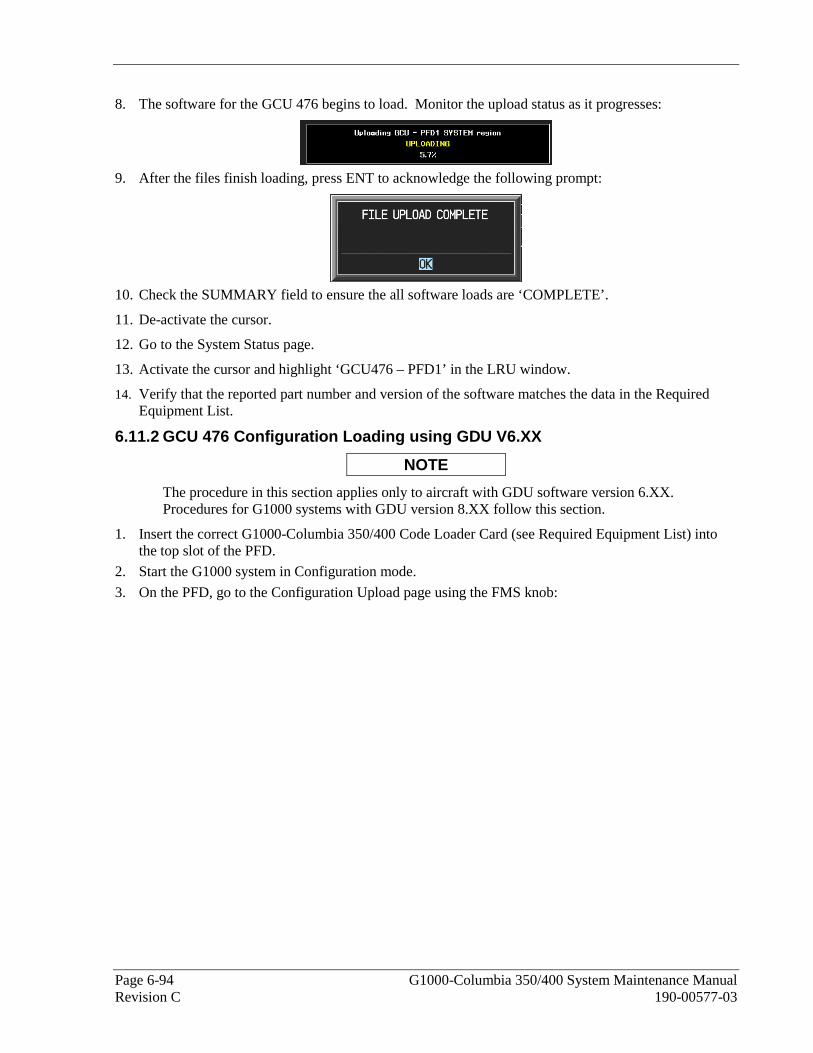
Page 6-94 G1000-Columbia 350/400 System Maintenance Manual Revision C 190-00577-03
8. The software for the GCU 476 begins to load. Monitor the upload status as it progresses:
9. After the files finish loading, press ENT to acknowledge the following prompt:
10. Check the SUMMARY field to ensure the all software loads are ‘COMPLETE’.
11. De-activate the cursor.
12. Go to the System Status page.
13. Activate the cursor and highlight ‘GCU476 – PFD1’ in the LRU window.
14. Verify that the reported part number and version of the software matches the data in the Required Equipment List.
6.11.2 GCU 476 Configuration Loading using GDU V6.XX
NOTE
The procedure in this section applies only to aircraft with GDU software version 6.XX. Procedures for G1000 systems with GDU version 8.XX follow this section.
1. Insert the correct G1000-Columbia 350/400 Code Loader Card (see Required Equipment List) into the top slot of the PFD.
2. Start the G1000 system in Configuration mode.
3. On the PFD, go to the Configuration Upload page using the FMS knob:

G1000-Columbia 350/400 System Maintenance Manual Page 6-95 190-00577-03 Revision C
4. Activate the cursor and use the small FMS knob to highlight the airframe type in the FILE field.
NOTE
Ensure that the correct airframe type is selected before proceeding; otherwise, incorrect configuration information will be loaded.
5. Press the ENT key to select the appropriate airframe type. Once an airframe type is selected the configuration files in the SECTION field will be displayed.
6. Using the FMS knob, highlight ‘GCU476’ in the FILE LIST field.
7. Press the LOAD softkey.
8. Select YES and press the ENT key to acknowledge the following prompt:
9. Monitor the status of the upload. When the upload is finished, press the ENT key to acknowledge the
following confirmation:
10. View the SUMMARY field and ensure that all items are ‘complete’, then de-activate the cursor.
11. After the software and configuration files are loaded, turn off the system and reinsert the Supplemental Database Cards in the bottom slot of each display. Be sure to insert the card removed from the MFD back into the MFD.
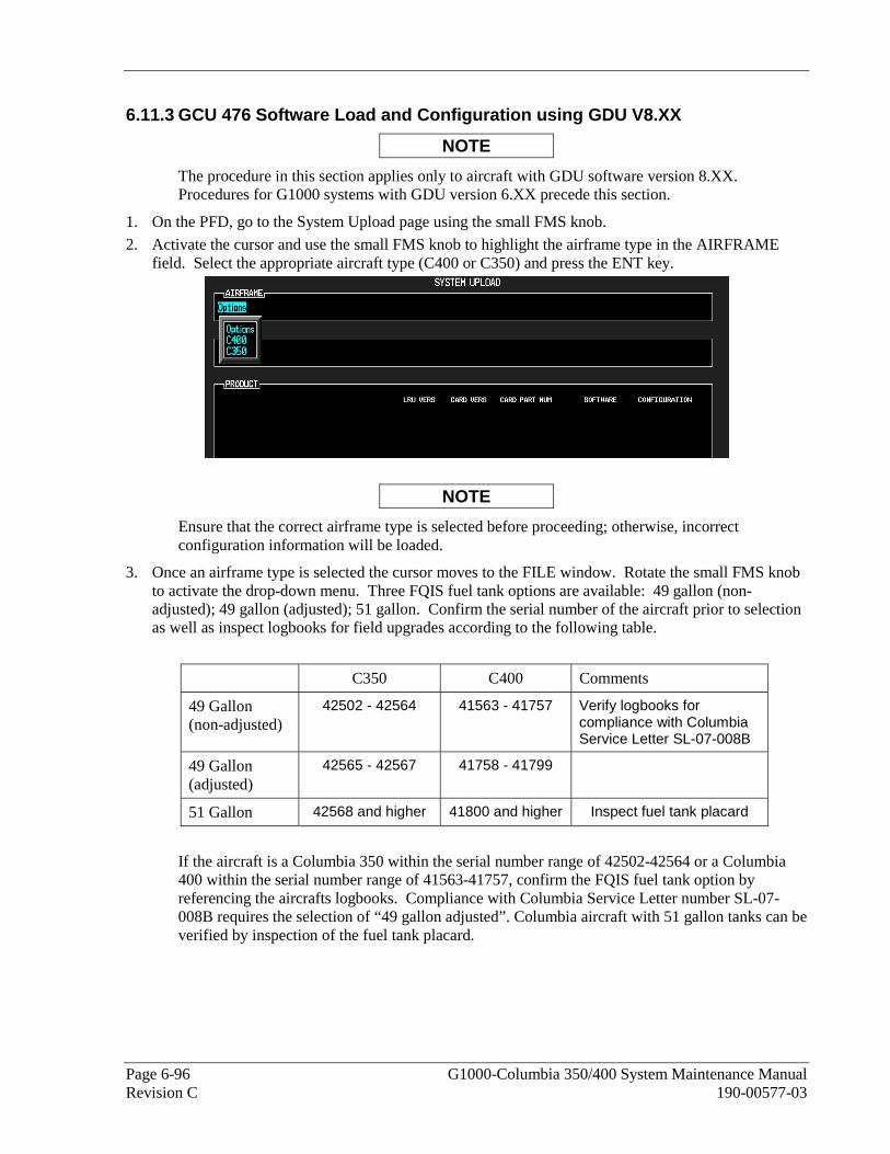
Page 6-96 G1000-Columbia 350/400 System Maintenance Manual Revision C 190-00577-03
6.11.3 GCU 476 Software Load and Configuration using GDU V8.XX
NOTE
The procedure in this section applies only to aircraft with GDU software version 8.XX. Procedures for G1000 systems with GDU version 6.XX precede this section.
1. On the PFD, go to the System Upload page using the small FMS knob.
2. Activate the cursor and use the small FMS knob to highlight the airframe type in the AIRFRAME field. Select the appropriate aircraft type (C400 or C350) and press the ENT key.
NOTE
Ensure that the correct airframe type is selected before proceeding; otherwise, incorrect configuration information will be loaded.
3. Once an airframe type is selected the cursor moves to the FILE window. Rotate the small FMS knob to activate the drop-down menu. Three FQIS fuel tank options are available: 49 gallon (non-adjusted); 49 gallon (adjusted); 51 gallon. Confirm the serial number of the aircraft prior to selection as well as inspect logbooks for field upgrades according to the following table.
C350 C400 Comments
49 Gallon (non-adjusted)
42502 - 42564 41563 - 41757 Verify logbooks for compliance with Columbia Service Letter SL-07-008B
49 Gallon (adjusted)
42565 - 42567 41758 - 41799
51 Gallon 42568 and higher 41800 and higher Inspect fuel tank placard
If the aircraft is a Columbia 350 within the serial number range of 42502-42564 or a Columbia 400 within the serial number range of 41563-41757, confirm the FQIS fuel tank option by referencing the aircrafts logbooks. Compliance with Columbia Service Letter number SL-07-008B requires the selection of “49 gallon adjusted”. Columbia aircraft with 51 gallon tanks can be verified by inspection of the fuel tank placard.

G1000-Columbia 350/400 System Maintenance Manual Page 6-97 190-00577-03 Revision C
NOTE
At this step, select to load WAAS or non-WAAS G1000 software.
4. The PRODUCT window will populate and display software and configuration file information for each G1000 LRU. The LRU VERS column shows the currently loaded software version in the LRU, whereas the CARD VERS column shows the LRU software version stored on the Loader Card. Each check designates a file to be loaded to the G1000.
By default, if an inequality between the LRU and CARD columns exists, the SOFTWARE CONFIGURATION boxes will be pre-selected (checked). By Default all of the CONFIGURATION boxes will be pre-selected.

Page 6-98 G1000-Columbia 350/400 System Maintenance Manual Revision C 190-00577-03
The following softkeys provide an easy way to select files:
CHK ALL: Selects all files, both configuration and software
CHK SW: Selects all software files only.
CHK CFG: Selects all configuration files only.
CLR ALL: Clears all selections.
5. After verifying that the GCU keypad software and configuration files are checked, press the LOAD softkey. It is acceptable to simply load the pre-selected software and config files. The G1000 system automatically begins loading software and default configuration files to the selected LRUs in the proper order.
6. When the system finishes loading, it prompts the technician accordingly. Press the ENT key to acknowledge that the upload is finished:
7. Verify that each column indicates in green when the loading process has finished and inspect the SUMMARY window as well to ensure that the load is successful.
8. After the software and configuration files are loaded, turn off the system and reinsert the Supplemental Database Cards in the bottom slot of each display. Be sure to insert the card removed from the MFD back into the MFD.
6.11.4 GCU 476 Boot Block Upgrade
The GCU 476 requires a boot block version of 3.01 or higher. If the configuration does not load it is an indicator that boot block upgrade is required (GCUs with older dates of manufacture may not have this version). If it was determined in one of the previous software loading procedures that the GCU 476 does not have boot block version 3.01 or higher, follow this procedure to update the GCU 476’s software boot block.
NOTE
It is critical for electrical power to remain on during the boot block update procedure. Take steps to ensure that a 28 VDC ground power supply is properly connected and is not disturbed during the update.
1. Obtain the required GCU 476 Boot Block loader card (SD Card,G1000,GCU476 BB v3.01 GPN 010-00533-02) from Garmin.
2. If required, remove any loader card present in the top slot of the PFD. Insert the boot block loader card into the top slot of the PFD.
3. On the PFD, press and hold the ENT key and apply system power to the G1000.
4. Press and hold the ENT key until the message “INITIALIZING SYSTEM” appears in the upper left corner of the PFD.
5. Release the ENT key.
6. On the PFD, use the FMS knob to get to the System Upload page.

G1000-Columbia 350/400 System Maintenance Manual Page 6-99 190-00577-03 Revision C
7. Activate the cursor and select GCU476 BB in the AIRFRAME field. Press the ENT key. The cursor will drop down to the FILE field.
8. Rotate the small inner FMS knob and select GCU Boot Block 3.01. Press the ENT key.
9. Verify that the SOFTWARE box is checked (see screen shot). Press the LOAD softkey. The GCU boot block will begin loading. Do not remove power while the update is in process.
10. The upload is completed when the message “Upload Complete, NO UPLOAD IN PROCESS” is displayed on the PFD. Press the ENT key to confirm software upload completion.
11. Power down the PFD. Remove the GCU Boot Block loader card and re-insert the correct G1000/GFC700 Software Loader card.
12. Load the GCU configuration per prior section.
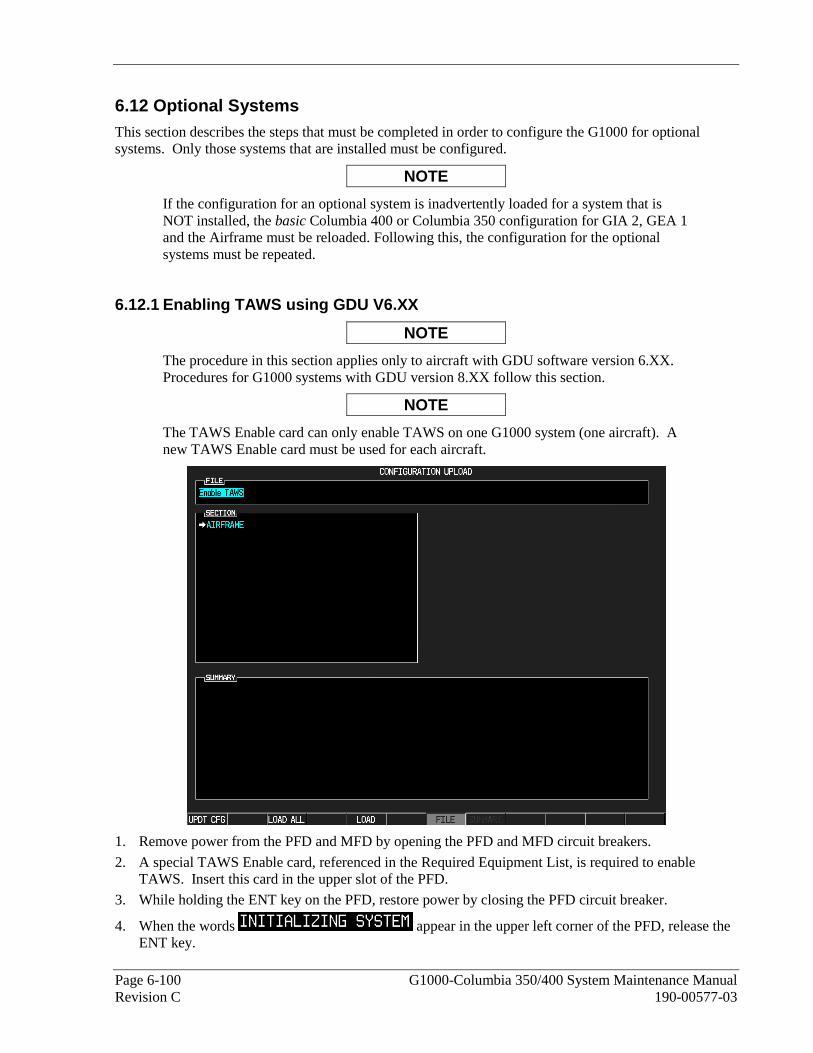
Page 6-100 G1000-Columbia 350/400 System Maintenance Manual Revision C 190-00577-03
6.12 Optional Systems This section describes the steps that must be completed in order to configure the G1000 for optional systems. Only those systems that are installed must be configured.
NOTE
If the configuration for an optional system is inadvertently loaded for a system that is NOT installed, the basic Columbia 400 or Columbia 350 configuration for GIA 2, GEA 1 and the Airframe must be reloaded. Following this, the configuration for the optional systems must be repeated.
6.12.1 Enabling TAWS using GDU V6.XX
NOTE
The procedure in this section applies only to aircraft with GDU software version 6.XX. Procedures for G1000 systems with GDU version 8.XX follow this section.
NOTE
The TAWS Enable card can only enable TAWS on one G1000 system (one aircraft). A new TAWS Enable card must be used for each aircraft.
1. Remove power from the PFD and MFD by opening the PFD and MFD circuit breakers.
2. A special TAWS Enable card, referenced in the Required Equipment List, is required to enable TAWS. Insert this card in the upper slot of the PFD.
3. While holding the ENT key on the PFD, restore power by closing the PFD circuit breaker.
4. When the words appear in the upper left corner of the PFD, release the ENT key.

G1000-Columbia 350/400 System Maintenance Manual Page 6-101 190-00577-03 Revision C
5. Repeat steps 3 and 4 for the MFD.
6. On the PFD, go to the Configuration Upload page using the small FMS knob.
7. Activate the cursor and use the small FMS knob to highlight ‘Enable TAWS’ in the FILE field.
8. Press the ENT key to select the Enable TAWS option. Once the option is selected the configuration files in the SECTION field will be displayed.
9. Press the LOAD ALL softkey.
10. Select YES and press ENT to acknowledge the following prompt:
11. Monitor the status of the upload. When the upload is finished, press the ENT key to acknowledge the
following confirmation:
12. View the SUMMARY field and ensure that the item is ‘COMPLETE’:
13. De-activate the cursor.
14. Power down the system and remove the TAWS Enable card from the PFD.
6.12.2 TAWS Activation using GDU V8.XX
NOTE
The procedure in this section applies only to aircraft with GDU software version 8.XX. Procedures for G1000 systems with GDU version 6.XX precede this section.
Perform this procedure only if the aircraft is to be equipped with the Garmin TAWS option.
1. Remove power from the PFD by opening the PFD circuit breaker.
2. A special TAWS Unlock card is required to enable TAWS. Refer to the Required Equipment List for the correct part number drawing. Insert this card in the upper slot of the PFD.
3. While holding the ENT key on the PFD and MFD, restore power to the displays.
4. When the words appear in the upper left corner of both displays, release the ENT keys.
5. On the PFD, go to the System Upload page using the FMS knob.
6. Activate the cursor. Use the small FMS knob to select CONFIGURATION FILES in the AIRFRAME field and press the ENT key.

Page 6-102 G1000-Columbia 350/400 System Maintenance Manual Revision C 190-00577-03
7. Highlight the FILE field. Use the small FMS knob to select the ‘Enable TAWS’ option and press the ENT key. Once the option is selected, the configuration files in the PRODUCT field will be displayed. All files should be checked. If not, press the CHK ALL softkey.
8. Press the LOAD softkey.
9. Monitor the status of the upload. When the upload is finished, press the ENT key to acknowledge the upload complete confirmation.
10. View the SUMMARY field and ensure that the item is ‘COMPLETE’.
11. De-activate the cursor.
12. Power down the system and remove the TAWS Enable card from the PFD.
6.12.3 ChartView
NOTE
ChartView databases are subscription-based and are to be procured by the aircraft owner directly from Jeppesen. This procedure is only required if the ChartView option is purchased by the customer.
1. Remove power from the PFD by opening the PFD circuit breaker.
2. A special ChartView Unlock card is required to activate this feature. Refer to the Required Equipment List for the correct part number. Insert this card in the upper slot of the PFD.
3. While holding the ENT key on the PFD and MFD, restore power to both displays by closing the PFD and MFD circuit breakers.
4. When the words appear in the upper left corner of the displays, release the ENT key.
5. On the PFD, go to the System Upload page using the FMS knob.
6. Activate the cursor. Use the small FMS knob to select CONFIGURATION FILES in the AIRFRAME field and press the ENT key.
7. Highlight the FILE field. Use the small FMS knob to select the “Enable ChartView” option and press the ENT key. Once the option is selected the configuration files in the PRODUCT field will be displayed. All files should be checked. If not, press the CHK ALL softkey.
8. Press the LOAD softkey.
9. Monitor the status of the upload. When the upload is finished, press the ENT key to acknowledge the upload complete confirmation.
10. View the SUMMARY field and ensure that the item is ‘COMPLETE’.
11. De-activate the cursor.
12. Power down the system and remove the ChartView Enable card from the PFD.
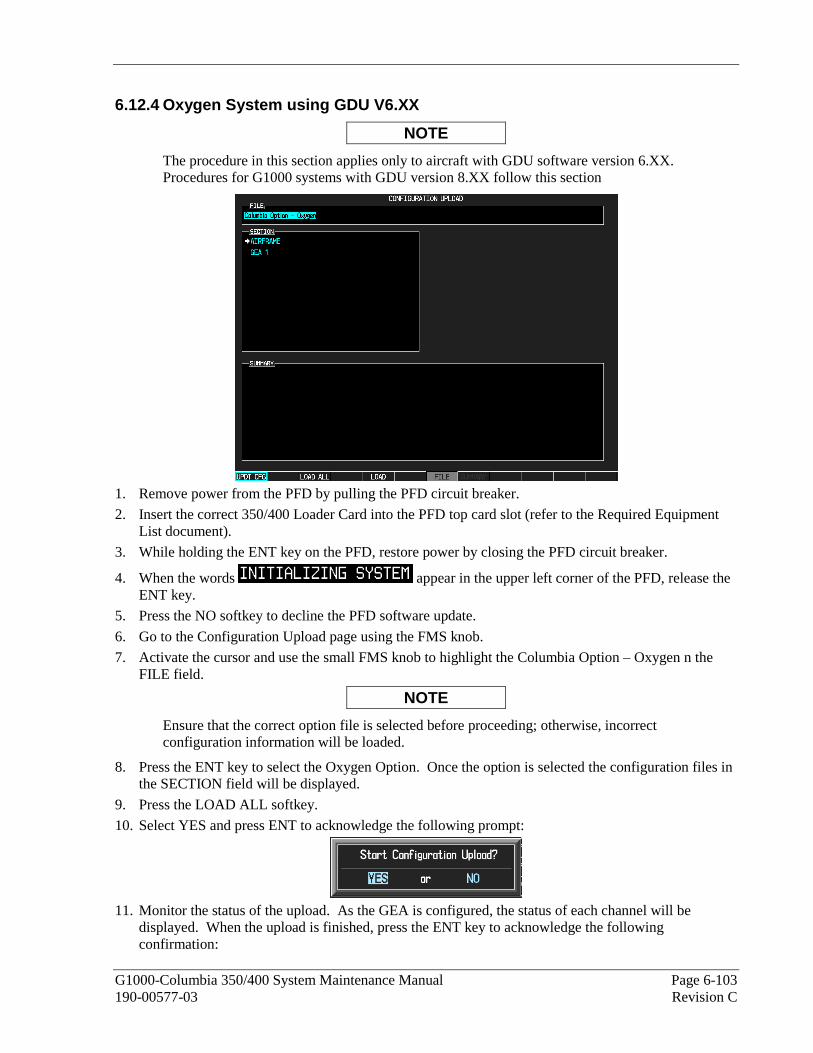
G1000-Columbia 350/400 System Maintenance Manual Page 6-103 190-00577-03 Revision C
6.12.4 Oxygen System using GDU V6.XX
NOTE
The procedure in this section applies only to aircraft with GDU software version 6.XX. Procedures for G1000 systems with GDU version 8.XX follow this section
1. Remove power from the PFD by pulling the PFD circuit breaker.
2. Insert the correct 350/400 Loader Card into the PFD top card slot (refer to the Required Equipment List document).
3. While holding the ENT key on the PFD, restore power by closing the PFD circuit breaker.
4. When the words appear in the upper left corner of the PFD, release the ENT key.
5. Press the NO softkey to decline the PFD software update.
6. Go to the Configuration Upload page using the FMS knob.
7. Activate the cursor and use the small FMS knob to highlight the Columbia Option – Oxygen n the FILE field.
NOTE
Ensure that the correct option file is selected before proceeding; otherwise, incorrect configuration information will be loaded.
8. Press the ENT key to select the Oxygen Option. Once the option is selected the configuration files in the SECTION field will be displayed.
9. Press the LOAD ALL softkey.
10. Select YES and press ENT to acknowledge the following prompt:
11. Monitor the status of the upload. As the GEA is configured, the status of each channel will be
displayed. When the upload is finished, press the ENT key to acknowledge the following confirmation:

Page 6-104 G1000-Columbia 350/400 System Maintenance Manual Revision C 190-00577-03
12. View the SUMMARY field and ensure that each item shown below is ‘COMPLETE’:
13. De-activate the cursor. 6.12.5 Oxygen System using GDU V8.XX
NOTE
The procedure in this section applies only to aircraft with GDU software version 8.XX. Procedures for G1000 systems with GDU version 6.XX precede this section.
1. At the System Upload page, activate cursor and rotate the FMS knob once to activate the AIRFRAME menu.
2. Select ‘Options’ from the AIRFRAME window and press ENT.
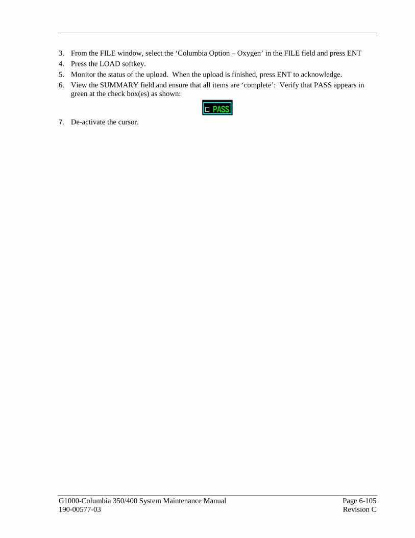
G1000-Columbia 350/400 System Maintenance Manual Page 6-105 190-00577-03 Revision C
3. From the FILE window, select the ‘Columbia Option – Oxygen’ in the FILE field and press ENT
4. Press the LOAD softkey.
5. Monitor the status of the upload. When the upload is finished, press ENT to acknowledge.
6. View the SUMMARY field and ensure that all items are ‘complete’: Verify that PASS appears in green at the check box(es) as shown:
7. De-activate the cursor.

Page 6-106 G1000-Columbia 350/400 System Maintenance Manual Revision C 190-00577-03
6.12.6 WX-500 Stormscope Configuration using GDU V6.XX
NOTE
The procedure in this section applies only to aircraft with GDU software version 6.XX. Procedures for G1000 systems with GDU version 8.XX follow this section
1. Remove power from the PFD by pulling the PFD circuit breaker.
2. Insert the correct 350/400 Loader Card into the PFD top card slot (refer to the Required Equipment List document).
3. While holding the ENT key on the PFD, restore power by closing the PFD circuit breaker.
4. When the words appear in the upper left corner of the PFD, release the ENT key.
5. Press the NO softkey to decline the PFD software update.
6. Go to the Configuration Upload page using the FMS knob.
7. Activate the cursor and use the small FMS knob to highlight the Columbia Option – WX-500 Stormscope in the FILE field.
NOTE
Ensure that the correct option file is selected before proceeding; otherwise, incorrect configuration information will be loaded.
8. Press the ENT key to select the Columbia Option – WX500 Once the option is selected the configuration files in the SECTION field will be displayed.
9. Press the LOAD ALL softkey.
10. Select YES and press ENT to acknowledge the following prompt:
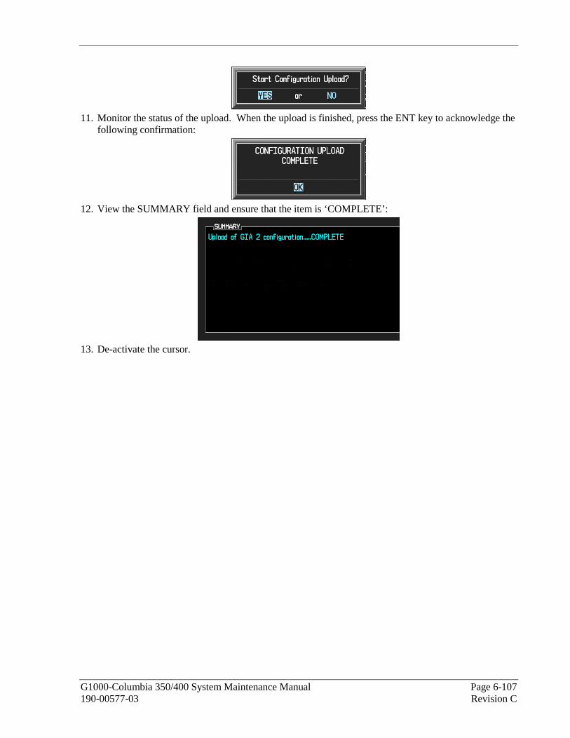
G1000-Columbia 350/400 System Maintenance Manual Page 6-107 190-00577-03 Revision C
11. Monitor the status of the upload. When the upload is finished, press the ENT key to acknowledge the
following confirmation:
12. View the SUMMARY field and ensure that the item is ‘COMPLETE’:
13. De-activate the cursor.

Page 6-108 G1000-Columbia 350/400 System Maintenance Manual Revision C 190-00577-03
6.12.7 WX-500 Stormscope using GDU V8.XX
NOTE
The procedure in this section applies only to aircraft with GDU software version 8.XX. Procedures for G1000 systems with GDU version 6.XX precede this section.
1. At the System Upload page, activate cursor and rotate the FMS knob once to activate the AIRFRAME menu.
2. Select ‘Options’ from the AIRFRAME window and press ENT.
3. From the FILE window, select the ‘Columbia Option – WX 500’ in the FILE field.
4. Press the LOAD softkey.
5. Monitor the status of the upload. When the upload is finished, press ENT to acknowledge.
6. View the SUMMARY field and ensure that all items are ‘complete’: Verify that PASS appears in green at the check box(es) as shown:
7. De-activate the cursor.
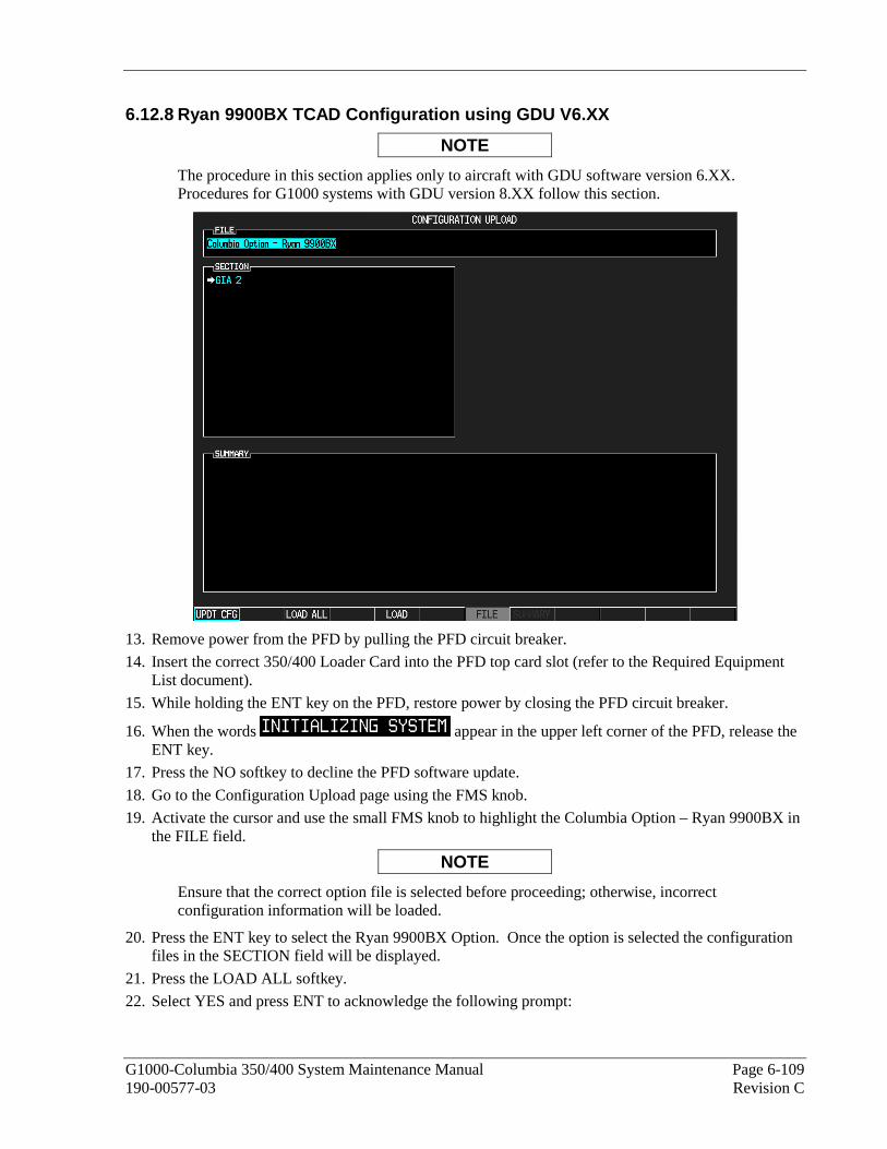
G1000-Columbia 350/400 System Maintenance Manual Page 6-109 190-00577-03 Revision C
6.12.8 Ryan 9900BX TCAD Configuration using GDU V6.XX
NOTE
The procedure in this section applies only to aircraft with GDU software version 6.XX. Procedures for G1000 systems with GDU version 8.XX follow this section.
13. Remove power from the PFD by pulling the PFD circuit breaker.
14. Insert the correct 350/400 Loader Card into the PFD top card slot (refer to the Required Equipment List document).
15. While holding the ENT key on the PFD, restore power by closing the PFD circuit breaker.
16. When the words appear in the upper left corner of the PFD, release the ENT key.
17. Press the NO softkey to decline the PFD software update.
18. Go to the Configuration Upload page using the FMS knob.
19. Activate the cursor and use the small FMS knob to highlight the Columbia Option – Ryan 9900BX in the FILE field.
NOTE
Ensure that the correct option file is selected before proceeding; otherwise, incorrect configuration information will be loaded.
20. Press the ENT key to select the Ryan 9900BX Option. Once the option is selected the configuration files in the SECTION field will be displayed.
21. Press the LOAD ALL softkey.
22. Select YES and press ENT to acknowledge the following prompt:

Page 6-110 G1000-Columbia 350/400 System Maintenance Manual Revision C 190-00577-03
23. Monitor the status of the upload. When the upload is finished, press the ENT key to acknowledge the
following confirmation:
24. View the SUMMARY field and ensure that the item is ‘COMPLETE’:
25. De-activate the cursor.

G1000-Columbia 350/400 System Maintenance Manual Page 6-111 190-00577-03 Revision C
6.12.9 Ryan 9900BX TCAD Configuration using GDU V8.XX
NOTE
The procedure in this section applies only to aircraft with GDU software version 8.XX. Procedures for G1000 systems with GDU version 6.XX precede this section.
1. At the System Upload page, activate cursor and rotate the FMS knob once to activate the AIRFRAME menu.
2. Select ‘Options’ from the AIRFRAME window and press ENT.
3. From the FILE window, select the ‘Columbia Option – Ryan 9900BX’ in the FILE field.
4. Press the LOAD softkey.
5. Monitor the status of the upload. When the upload is finished, press ENT to acknowledge.
6. View the SUMMARY field and ensure that all items are ‘complete’: Verify that PASS appears in green at the check box(es) as shown:
7. De-activate the cursor.

Page 6-112 G1000-Columbia 350/400 System Maintenance Manual Revision C 190-00577-03
6.13 Complete G1000 software load using GDU V8.XX
NOTE
Throughout this document, many screen shots and examples are used to illustrate the software and configuration loading process. Although every effort has been made to ensure accuracy of such examples, changes may occur. Always refer to the Required Equipment List for the correct software file names, versions and part numbers.
This section provides an overview of a complete software/configuration procedure for instances where the entire G1000 system software version is to be re-loaded and/or updated. The following diagram depicts an overview of the entire software/configuration sequence for the G1000 system. It should be noted that in some cases, not all LRU software versions are updated at the same time. LRUs with unchanged S/W versions may be skipped during the process. All software versions must be verified at the beginning and end of the procedure and must agree with the data presented in the Required Equipment List. If any problems are encountered during the loading process, see Section 6.13 for troubleshooting.
After the software and configuration data has been loaded, the Aviation Database must be loaded according to Section 6.1.4 Following this, perform the tests for each LRU as specified in Section 6, as applicable.
After completing all LRU tests, perform the final system checkout as specified in Section 7.
Be sure to record the maintenance performed in the appropriate aircraft maintenance documentation.
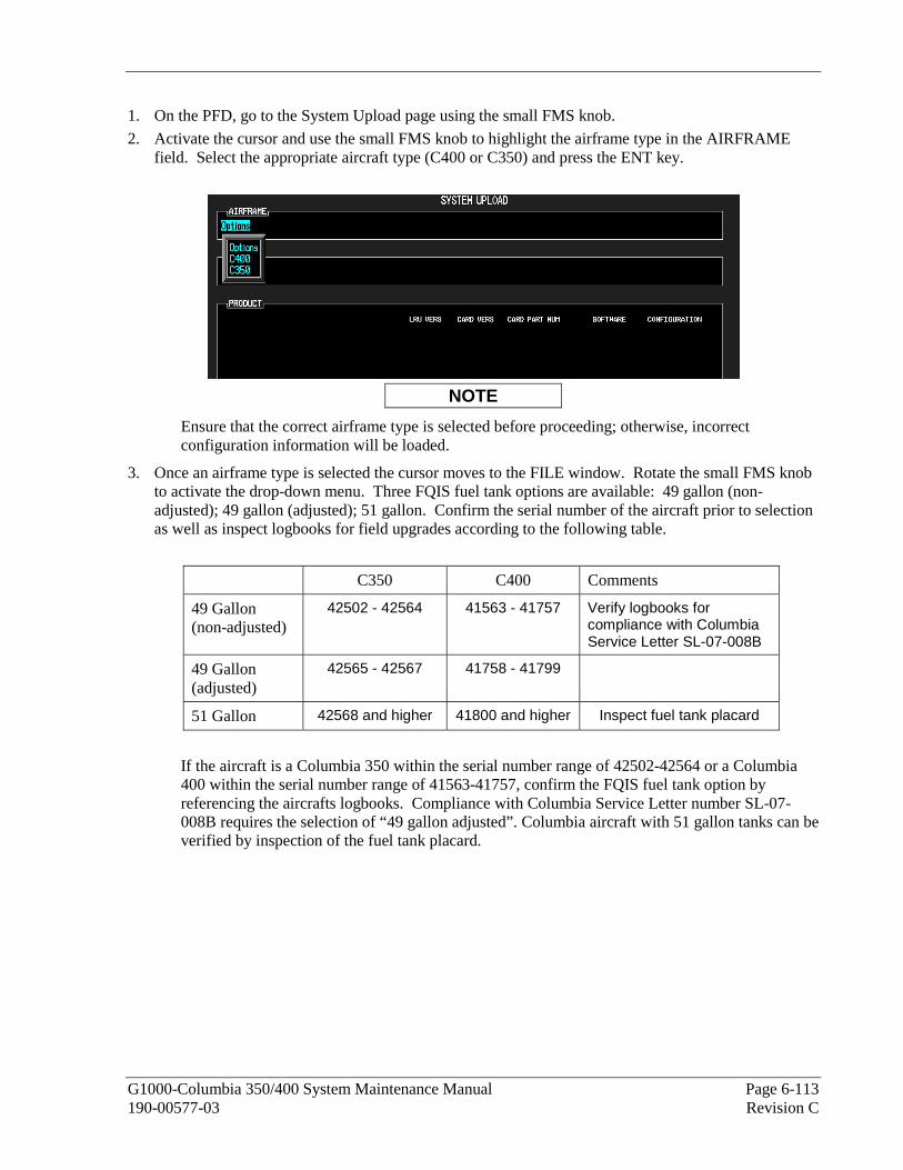
G1000-Columbia 350/400 System Maintenance Manual Page 6-113 190-00577-03 Revision C
1. On the PFD, go to the System Upload page using the small FMS knob.
2. Activate the cursor and use the small FMS knob to highlight the airframe type in the AIRFRAME field. Select the appropriate aircraft type (C400 or C350) and press the ENT key.
NOTE
Ensure that the correct airframe type is selected before proceeding; otherwise, incorrect configuration information will be loaded.
3. Once an airframe type is selected the cursor moves to the FILE window. Rotate the small FMS knob to activate the drop-down menu. Three FQIS fuel tank options are available: 49 gallon (non-adjusted); 49 gallon (adjusted); 51 gallon. Confirm the serial number of the aircraft prior to selection as well as inspect logbooks for field upgrades according to the following table.
C350 C400 Comments
49 Gallon (non-adjusted)
42502 - 42564 41563 - 41757 Verify logbooks for compliance with Columbia Service Letter SL-07-008B
49 Gallon (adjusted)
42565 - 42567 41758 - 41799
51 Gallon 42568 and higher 41800 and higher Inspect fuel tank placard
If the aircraft is a Columbia 350 within the serial number range of 42502-42564 or a Columbia 400 within the serial number range of 41563-41757, confirm the FQIS fuel tank option by referencing the aircrafts logbooks. Compliance with Columbia Service Letter number SL-07-008B requires the selection of “49 gallon adjusted”. Columbia aircraft with 51 gallon tanks can be verified by inspection of the fuel tank placard.
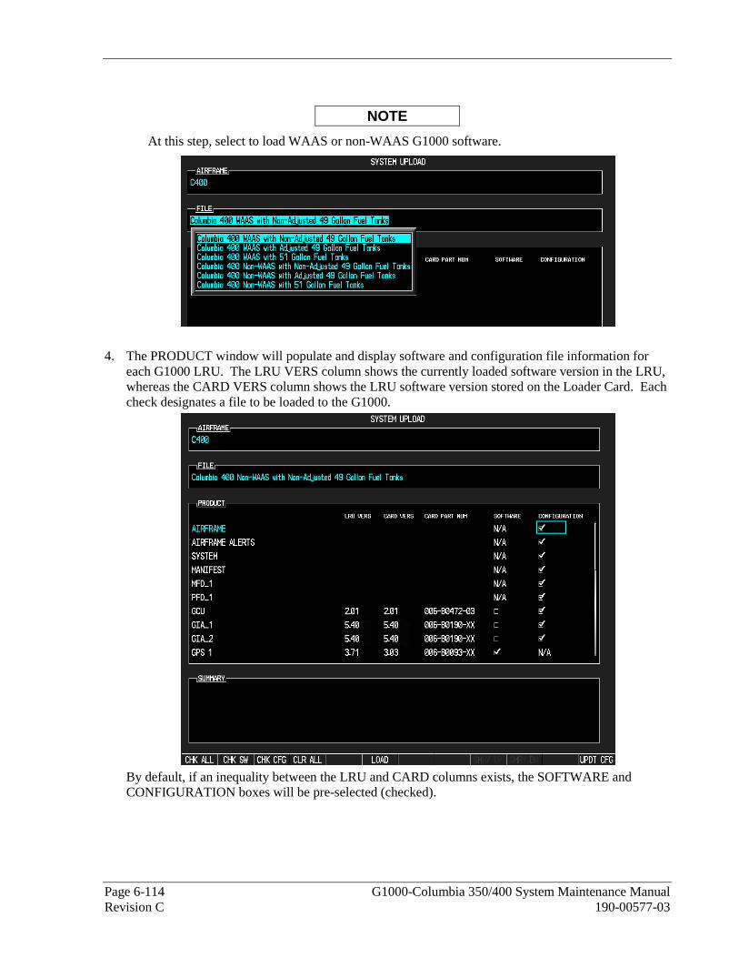
Page 6-114 G1000-Columbia 350/400 System Maintenance Manual Revision C 190-00577-03
NOTE
At this step, select to load WAAS or non-WAAS G1000 software.
4. The PRODUCT window will populate and display software and configuration file information for each G1000 LRU. The LRU VERS column shows the currently loaded software version in the LRU, whereas the CARD VERS column shows the LRU software version stored on the Loader Card. Each check designates a file to be loaded to the G1000.
By default, if an inequality between the LRU and CARD columns exists, the SOFTWARE and CONFIGURATION boxes will be pre-selected (checked).

G1000-Columbia 350/400 System Maintenance Manual Page 6-115 190-00577-03 Revision C
The following softkeys provide an easy way to select files:
CHK ALL: Selects all files, both configuration and software
CHK SW: Selects all software files only.
CHK CFG: Selects all configuration files only.
CLR ALL: Clears all selections.
NOTE
If this is the first time loading software and configuration to a new installation, it is advised to leave all check boxes selected.
5. After verifying that the desired software and configuration files are checked, press the LOAD softkey. It is acceptable to simply load the pre-selected software and config files. The G1000 system automatically begins loading software and default configuration files to the selected LRUs in the proper order.
6. When the system finishes loading, it prompts the technician accordingly. Press the ENT key to acknowledge that the upload is finished:
7. Verify that each column indicates in green when the loading process has finished and inspect the SUMMARY window as well to ensure that the load is successful.
8. After the software and configuration files are loaded, turn off the system and reinsert the Supplemental Database Cards in the bottom slot of each display. Be sure to insert the card removed from the MFD back into the MFD.

Page 6-116 G1000-Columbia 350/400 System Maintenance Manual Revision C 190-00577-03
6.14 Software/Configuration Troubleshooting
Problem Solutions GDU 1040 PFD or GDU 1042 MFD display does not power up.
• Ensure that the criteria listed in 6.14.1 are fulfilled for the applicable situation.
• Ensure power is present at display connector. • Replace display.
Software file load fails:
• Ensure that criteria listed in 6.14.1 are fulfilled for the applicable situation.
• Ensure that LRU is reporting data on System Status page (LRU is ‘ONLINE’). Check data path wiring as needed.
• Retry software file load or try using a different card.
• Ensure that the MFD is not touched during the loading process, unless specifically instructed to do so.
• Ensure that LRU part number is compatible with software version and Loader Card. Refer to Required Equipment List.
• Replace LRU. Configuration file load fails:
• Ensure that criteria listed in 6.14.1 are fulfilled for the applicable situation.
• Ensure that LRU is reporting data on System Status page (LRU is ‘ONLINE’). Check data path wiring as needed.
• Retry configuration file load or try using a different card.
• Ensure that the MFD is not touched during the loading process, unless specifically instructed to do so.
• Ensure that LRU part number is compatible with Loader Card. Refer to Required Equipment List.
• Replace LRU. GIA1 and/or GIA2 to ‘LRU’ data path not working • Ensure that criteria listed in 6.14.1 are
fulfilled for the applicable situation. • Ensure GIA1 and GIA2 are configured
correctly. • Check wiring, connectors & pins as needed.
Software File Mismatch Alert appears in lower right corner of PFD when started in normal mode:
• Ensure that proper software file part number and version were loaded to LRU.
• Check and ensure that correct Loader Card was used during load process.
• Reload software to LRU. • Reload ‘MANIFEST’ configuration file to
PFD.

G1000-Columbia 350/400 System Maintenance Manual Page 6-117 190-00577-03 Revision C
6.14.1 System Communication Hierarchy
The following criteria must be satisfied to be able to perform these desired operations:
Desired Operation Criteria for Success Load Software to GDU 1040 PFD or GDU 1042 MFD Displays
G1000-Columbia 350/400 Code Loader Card must be inserted in top slot for each display to be loaded.
• ENT keys must be held during power up of display.
• Power on only one display at a time during software loading.
Load AIRFRAME, SYSTEM, MFD1, PFD1, and MANIFEST configuration files to MFD and PFD
G1000-Columbia 350/400 Code Loader Card must be inserted in top slot of PFD.
PFD and MFD must be powered on.
PFD and MFD must have correct software.
Load Software/Configuration files to GIA 63s G1000-Columbia 350/400 Code Loader Card must be inserted in top slot of PFD.
G1000/350/400 system must be powered on.
PFD and MFD must have correct software.
PFD and MFD must be successfully configured with AIRFRAME, SYSTEM, MANIFEST, MFD1, and PFD1 configuration files.
Load Software/Configuration files to:
- GMA 1347 - GDC 74A - GEA 71 - GRS 77 (software only) - GTX 33 - GDL 69A - GSA 81’s - GTA 82 - GCU 476
G1000-Columbia 350/400 Code Loader Card must be inserted into PFD top slot.
G1000 must be powered on.
PFD and MFD must have correct software and configuration settings.
GIA 63s must have correct software.
GIA 63s must be successfully configured with GIA1 and GIA2 configuration files.
Data path from GIA1 to each LRU must be operational.

Page 6-118 G1000-Columbia 350/400 System Maintenance Manual Revision C 190-00577-03
This Page Intentionally Left Blank

G1000-Columbia 350/400 System Maintenance Manual Page 7-1 190-00577-03 Revision C
7 SYSTEM RETURN TO SERVICE PROCEDURE This final checkout tests various secondary communications paths to ensure that the paths function correctly. Perform the following steps and verify the results of each test.
7.1 GIA Failure Test
Step Desired Result Single GIA Failure Conditions:
1. Remove power from GIA 1 by pulling INTEG AVION 1 and COM 1 breakers.
2. Restore power to GIA 1. Allow to re-acquire satellites.
GIA 1 Failure - For a GIA 1 failure, only the following shall flag invalid:
• COM/NAV 1 field.
• NAV 1 CDI loses deviation bar. • TAWS FAIL
• AFCS
3. Remove power from GIA 2 by pulling INTEG AVION 2 and COM 2 breakers.
4. Restore power to GIA 2.
GIA 2 Power Failure - For a GIA 2 failure, only the following shall flag invalid:
• COM/NAV 2 field.
• NAV 2 CDI loses deviation bar. • TAWS FAIL
• AFCS • CO Detector Fail
• Stormscope Fail (if installed)
• TCAD Altitude Invalid (if installed)
Dual GIA Failure Conditions:
1. Remove power from both GIA units.
2. Restore power to both GIA units.
Dual GIA Failure - For a dual GIA failure, only the following shall occur:
• COM/NAV 1 & COM/NAV 2 fields flag invalid. • GPS CDI flags INTEG on PFD.
• NAV 1, 2 CDI loses deviation bar.
• XPDR field flags invalid on PFD. • Engine Instrument field flags invalid on MFD.
• TAWS FAIL
• AFCS fail • CO Detector Fail
• Stormscope Fail (if installed)
• TCAD Altitude Invalid (if installed) • GMA 1 Fail (annunciation only)
• AHRS 1 Not Receiving GPS Info alert
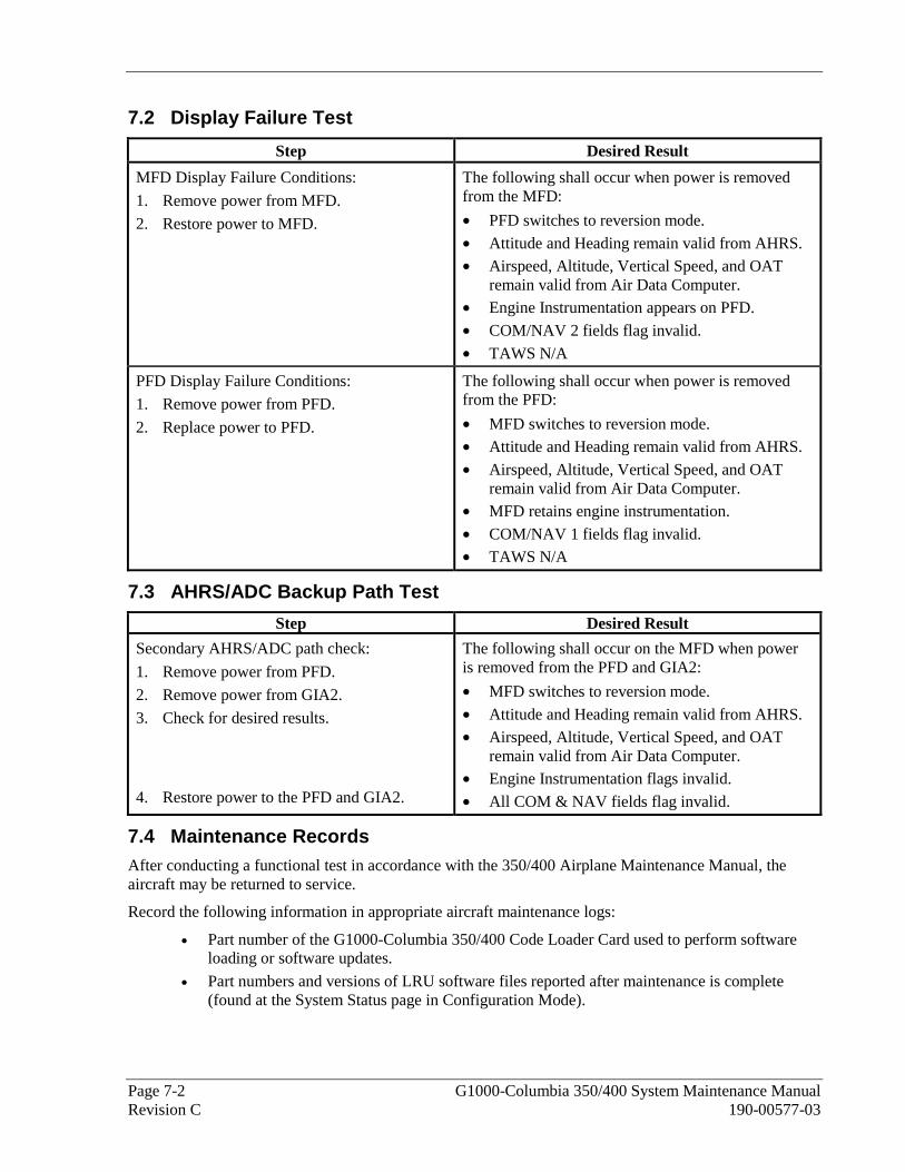
Page 7-2 G1000-Columbia 350/400 System Maintenance Manual Revision C 190-00577-03
7.2 Display Failure Test
Step Desired Result
MFD Display Failure Conditions:
1. Remove power from MFD.
2. Restore power to MFD.
The following shall occur when power is removed from the MFD:
• PFD switches to reversion mode.
• Attitude and Heading remain valid from AHRS. • Airspeed, Altitude, Vertical Speed, and OAT
remain valid from Air Data Computer. • Engine Instrumentation appears on PFD.
• COM/NAV 2 fields flag invalid.
• TAWS N/A
PFD Display Failure Conditions:
1. Remove power from PFD.
2. Replace power to PFD.
The following shall occur when power is removed from the PFD:
• MFD switches to reversion mode. • Attitude and Heading remain valid from AHRS.
• Airspeed, Altitude, Vertical Speed, and OAT remain valid from Air Data Computer.
• MFD retains engine instrumentation.
• COM/NAV 1 fields flag invalid. • TAWS N/A
7.3 AHRS/ADC Backup Path Test
Step Desired Result
Secondary AHRS/ADC path check:
1. Remove power from PFD.
2. Remove power from GIA2.
3. Check for desired results.
4. Restore power to the PFD and GIA2.
The following shall occur on the MFD when power is removed from the PFD and GIA2:
• MFD switches to reversion mode.
• Attitude and Heading remain valid from AHRS. • Airspeed, Altitude, Vertical Speed, and OAT
remain valid from Air Data Computer. • Engine Instrumentation flags invalid.
• All COM & NAV fields flag invalid.
7.4 Maintenance Records After conducting a functional test in accordance with the 350/400 Airplane Maintenance Manual, the aircraft may be returned to service.
Record the following information in appropriate aircraft maintenance logs:
• Part number of the G1000-Columbia 350/400 Code Loader Card used to perform software loading or software updates.
• Part numbers and versions of LRU software files reported after maintenance is complete (found at the System Status page in Configuration Mode).

G1000-Columbia 350/400 System Maintenance Manual Page 8-1 190-00577-03 Revision C
8 REQUIRED EQUIPMENT
8.1 G1000 Required Equipment See the latest revision of “Required Equipment List” (RB011002) for the specific loader card part number, software part number, and software version.
8.2 Weight & Balance See the latest revision of the Modification Summary, part number 005-00230-11.

Page 8-2 G1000-Columbia 350/400 System Maintenance Manual Revision C 190-00577-03
This Page Intentionally Left Blank