Embed Size (px)
Citation preview

G050371-00-D
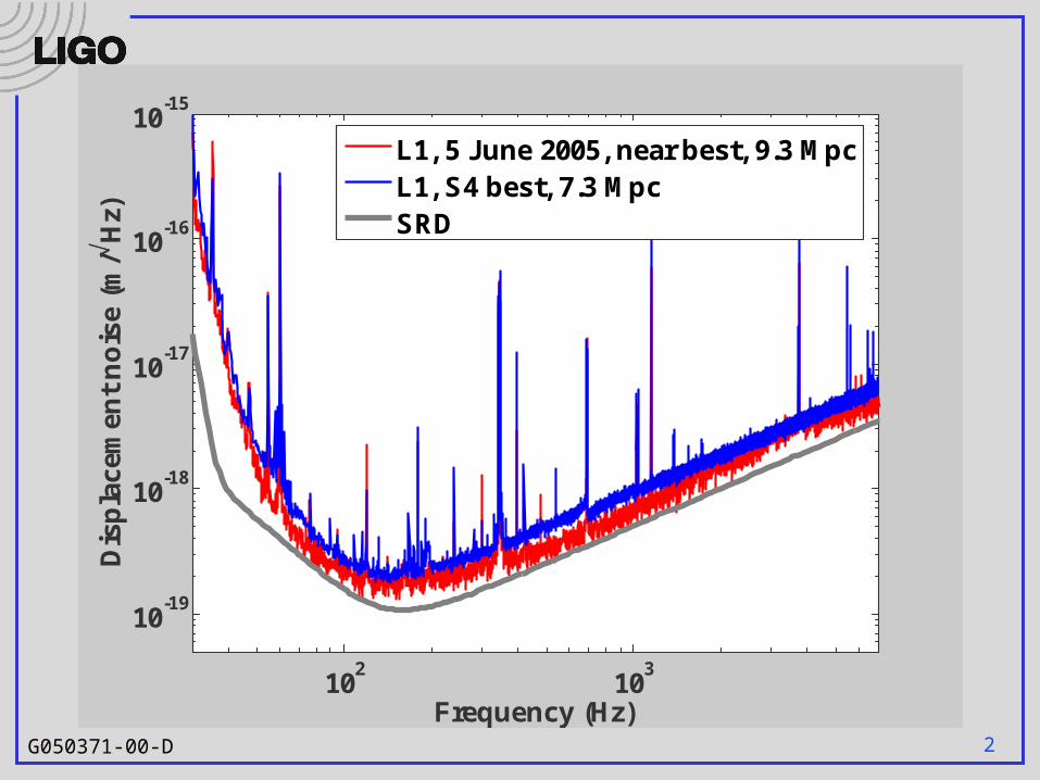
Commissioning Report
P Fritschel
LSC meeting, LHO
15 Aug 2005
2G050371-00-D
102
103
10-19
10-18
10-17
10-16
10-15
Frequency (Hz)
Dis
pla
cem
ent
no
ise
(m/
Hz)
L1, 5 June 2005, near best, 9.3 MpcL1, S4 best, 7.3 MpcSRD
3G050371-00-D
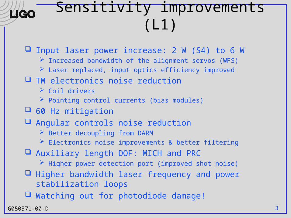
Sensitivity improvements (L1)
Input laser power increase: 2 W (S4) to 6 W Increased bandwidth of the alignment servos (WFS) Laser replaced, input optics efficiency improved
TM electronics noise reduction Coil drivers Pointing control currents (bias modules)
60 Hz mitigation Angular controls noise reduction
Better decoupling from DARM Electronics noise improvements & better filtering
Auxiliary length DOF: MICH and PRC Higher power detection port (improved shot noise)
Higher bandwidth laser frequency and power stabilization loops Watching out for photodiode damage!
4G050371-00-D
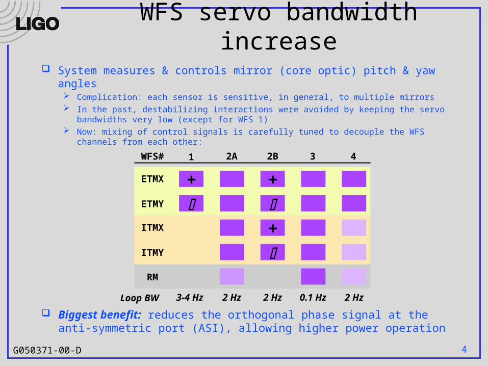
WFS servo bandwidth increase System measures & controls mirror (core optic) pitch & yaw angles
Complication: each sensor is sensitive, in general, to multiple mirrors In the past, destabilizing interactions were avoided by keeping the servo bandwidths
very low (except for WFS 1) Now: mixing of control signals is carefully tuned to decouple the WFS channels from
each other:
+
1 2A 2B 3 4
+
+
ETMX
ETMY
ITMX
ITMY
RM
WFS#
Loop BW 3-4 Hz 2 Hz 2 Hz 2 Hz0.1 Hz
Biggest benefit: reduces the orthogonal phase signal at the anti-symmetric port (ASI), allowing higher power operation

5G050371-00-D
Laser power: woes & triumphs
L1: laser replaced after S4 with a recently refurbished unit Failed shortly after installation Replaced with another refurbished unit (sent from LHO) Optical efficiency from laser output to mode cleaner input
significantly increased Replaced pre-mode cleaner, optimized components, … Close to 80% efficiency from laser to input to vacuum
Max input power now 8 Watts
H2: power amplifier still the original unit from Dec ’98 Replacement with refurbished unit is imminent
Lightwave Electronics acquired by JDS Uniphase several months ago Has delayed the repair of our lasers: currently have no 10 W spares
in-house
6G050371-00-D
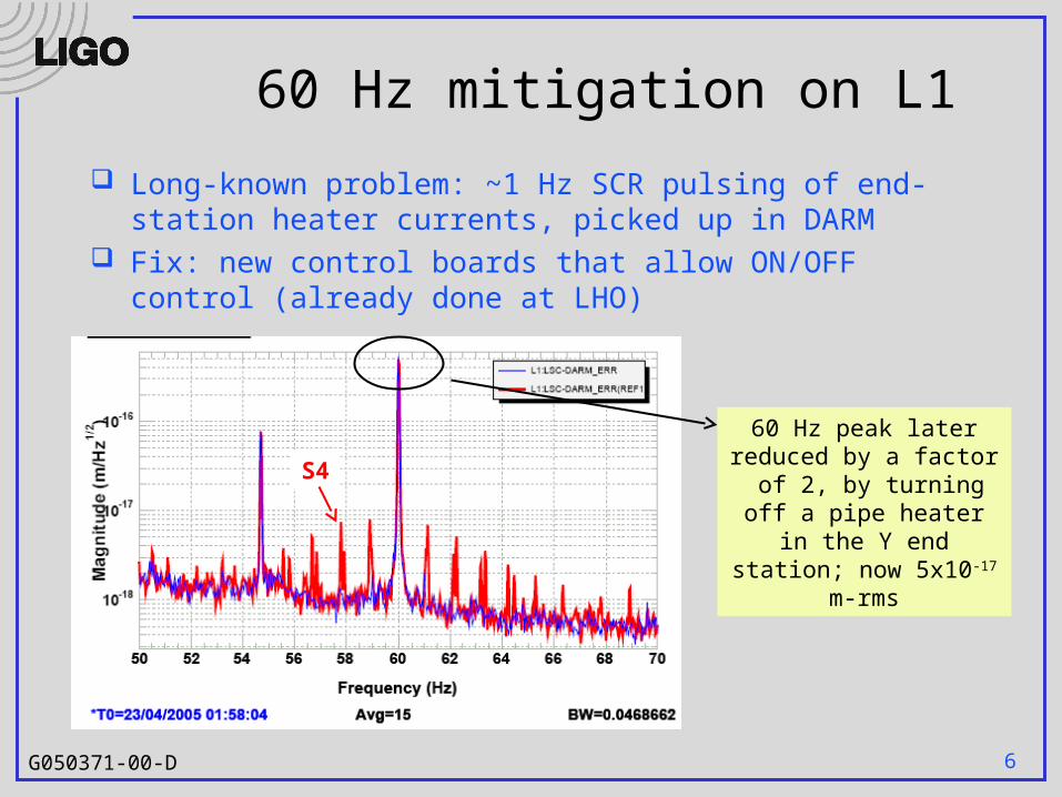
60 Hz mitigation on L1
Long-known problem: ~1 Hz SCR pulsing of end-station heater currents, picked up in DARM
Fix: new control boards that allow ON/OFF control (already done at LHO)
S4
60 Hz peak later reduced by a factor of 2, by
turning off a pipe heater in the Y end station; now
5x10-17 m-rms

7G050371-00-D
Ongoing story of photodiode damage
Loss-of-lock: full beamsplitter power can be dumped out the AS port, in a ~10 msec width pulse Mechanical shutter cuts off the
beam, with a trigger delay of about 6 msec
PD damage due to Too high trigger level Shutter too slow (wrong type)
Damaged PDs can be noisy Solution (in progress):
All shutters of proper type Carefully set trigger level Looking at cutting off PD bias
voltage on lock-loss
~100 W
5 msec
Red: replaced damaged PDs

8G050371-00-D
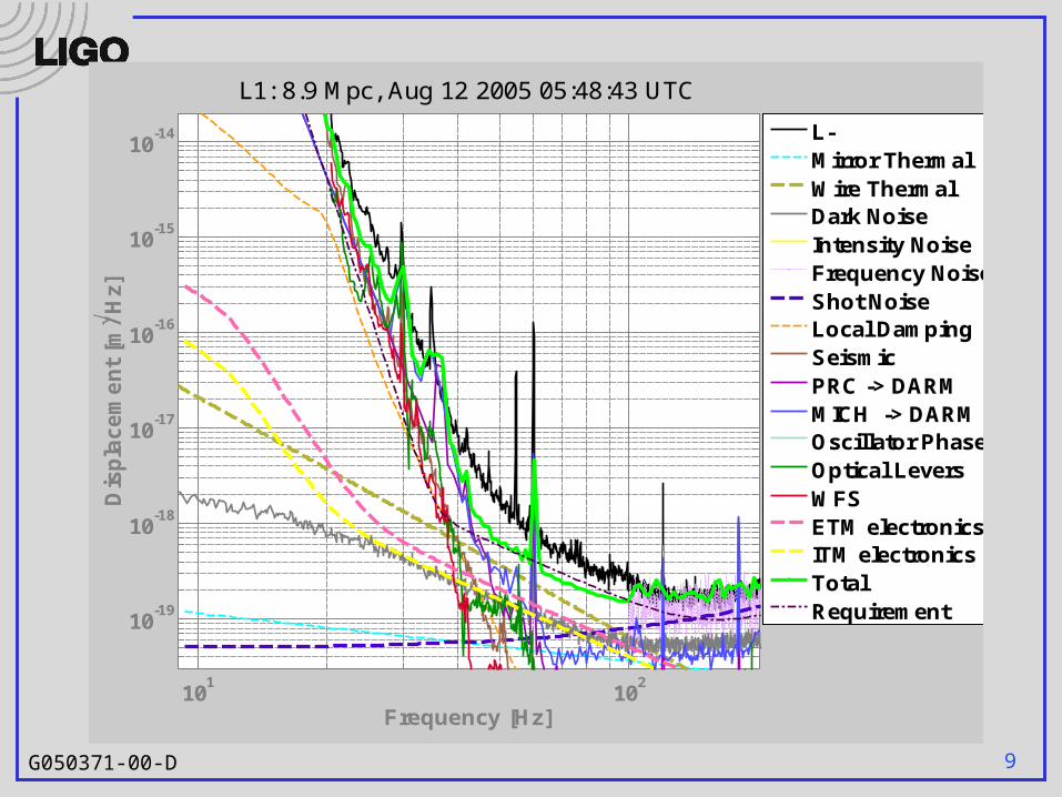
L1 Noise Budget
101
102
103
10-19
10-18
10-17
10-16
10-15
10-14
Frequency [Hz]
Dis
pla
ce
me
nt
[m/
Hz]
L1: 8.9 Mpc, Aug 12 2005 05:48:43 UTC
L-Mirror ThermalWire ThermalDark NoiseIntensity NoiseFrequency NoiseShot NoiseLocal DampingSeismicPRC -> DARMMICH -> DARMOscillator PhaseOptical LeversWFSETM electronicsITM electronicsTotalRequirement
9G050371-00-D
101
102
10-19
10-18
10-17
10-16
10-15
10-14
Frequency [Hz]
Dis
pla
ce
me
nt
[m/
Hz]
L1: 8.9 Mpc, Aug 12 2005 05:48:43 UTC
L-Mirror ThermalWire ThermalDark NoiseIntensity NoiseFrequency NoiseShot NoiseLocal DampingSeismicPRC -> DARMMICH -> DARMOscillator PhaseOptical LeversWFSETM electronicsITM electronicsTotalRequirement
10G050371-00-D
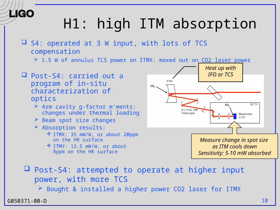
H1: high ITM absorption
Post-S4: carried out a program of in-situ characterization of optics Arm cavity g-factor m’ments:
changes under thermal loading Beam spot size changes Absorption results:
ITMX: 35 mW/W, or about 20ppm on the HR surface
ITMY: 13.5 mW/W, or about 8ppm on the HR surface
S4: operated at 3 W input, with lots of TCS compensation 1.5 W of annulus TCS power on ITMX: maxed out on CO2 laser power
Post-S4: attempted to operate at higher input power, with more TCS Bought & installed a higher power CO2 laser for ITMX
Measure change in spot size as ITM cools down
Sensitivity: 5-10 mW absorbed
Heat up withIFO or TCS
11G050371-00-D
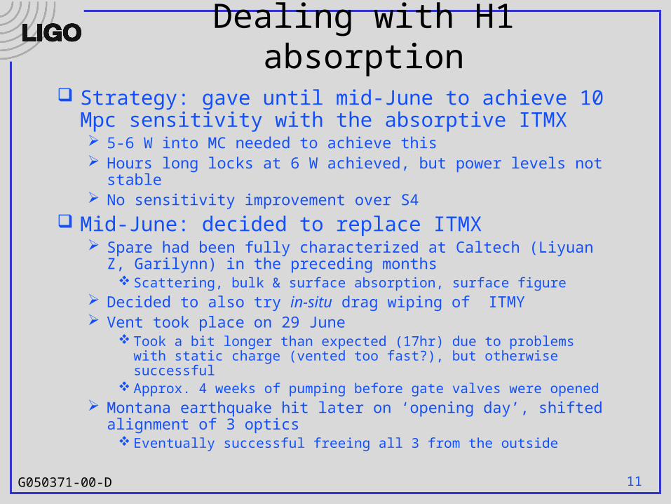
Dealing with H1 absorption Strategy: gave until mid-June to achieve 10 Mpc
sensitivity with the absorptive ITMX 5-6 W into MC needed to achieve this Hours long locks at 6 W achieved, but power levels not stable No sensitivity improvement over S4
Mid-June: decided to replace ITMX Spare had been fully characterized at Caltech (Liyuan Z, Garilynn)
in the preceding months Scattering, bulk & surface absorption, surface figure
Decided to also try in-situ drag wiping of ITMY Vent took place on 29 June
Took a bit longer than expected (17hr) due to problems with static charge (vented too fast?), but otherwise successful
Approx. 4 weeks of pumping before gate valves were opened Montana earthquake hit later on ‘opening day’, shifted alignment of
3 optics Eventually successful freeing all 3 from the outside

12G050371-00-D
And now?
IFO has been run at 4.5 W in MC: no annulus TCS needed, 7-8 Mpc sensitivity achieved
Beam size measurements repeated:
Forensics on the extracted ITM being carried out at Caltech So far no abnormal absorption has been seen!
All in all, a very successful operation, thanks to: Dave O, Rick S, Sam W, Keita K, Cheryl V, Gerardo M, Gari B, Liyuan Z,
Helena A, Doug C, Betsy B, Gary T, John W, Kyle R
ITMX ITMY
Before 35 mW/W 13.5 mW/W
Now < 3 mW/W 3 mW/W

13G050371-00-D
Upconversion from stack motion
Using HEPI, increase the suspension point motion at 1.5 Hz by a factor of 5
DARM noise increases by a factor of ~5 over a wide band
Effect first seen at LHO*, & measured recently at LLO:
*see Robert Schofield’s DetChar talk
14G050371-00-D
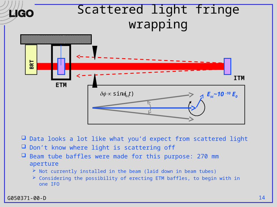
Scattered light fringe wrappingB
RT
ITMETM
Esc~10 -10 E0)sin( sct
Data looks a lot like what you’d expect from scattered light Don’t know where light is scattering off Beam tube baffles were made for this purpose: 270 mm
aperture Not currently installed in the beam (laid down in beam tubes) Considering the possibility of erecting ETM baffles, to begin with in one IFO
15G050371-00-D
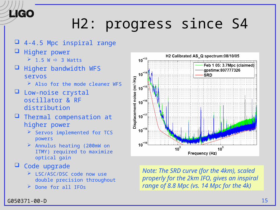
H2: progress since S4 4-4.5 Mpc inspiral range Higher power
1.5 W 3 Watts
Higher bandwidth WFS servos Also for the mode cleaner WFS
Low-noise crystal oscillator & RF distribution
Thermal compensation at higher power Servos implemented for TCS
powers Annulus heating (200mW on ITMY)
required to maximize optical gain
Code upgrade LSC/ASC/DSC code now use
double precision throughout Done for all IFOs
Note: The SRD curve (for the 4km), scaled properly for the 2km IFO, gives an inspiral range of 8.8 Mpc (vs. 14 Mpc for the 4k)
16G050371-00-D
Now till S5 REFL port beam pointing stabilization
L1, H1: heating distortion in the Faraday causes the REFL port beam to drift with power
Slow servo to stabilize position on REFL table to be implemented in September
H2 laser replacement soon Timing system upgrade: to be installed on H2 New acoustic enclosures for H1 and H2 REFL tables
Cut down on H1-H2 correlated noise
H2: test of floating the AS port detection table Frequency noise reduction
Second detector at REFL port that (in principle) has a better SNR for frequency noise (more power, different modulation freq)
AS port dust covers for L1 Bias module fixes for LHO Frequency multiplier for crystal oscillator, LHO

17G050371-00-D
During S5
S5 will not be completely ‘hands-off’ Expect to take 1-2 week breaks (every few months?)
to try improvements For example:
Beam tube baffles Power increase steps: new PMC, new laser Propagate timing system upgrade

18G050371-00-D
101
102
103
10-20
10-19
10-18
10-17
10-16
10-15
10-14
Frequency [Hz]
Dis
plac
emen
t [m
/H
z]H1: 9.8 Mpc, Aug 15 2005 00:58:00 UTC DARM
MICH
PRC
Oscillator
OpticalLevers
WFS
OSEM
Seismic
ETM
ITM
BS
SusTherm
IntTherm
Shot
Dark
Intensity
Frequency
Total
SRD