Embed Size (px)
Citation preview

Solid State Logic
G Series Systems
Operator’s Shortform Guide
82S6MGS010A

G Series Shortform Guide
Solid State Logic
Begbroke, Oxford, England OX5 1RU • +44 (0)1865 842300
320 West 46th Street, 2nd Floor, New York, NY 10036, USA • + 1 (1) 212 315 11116255 Sunset Boulevard, Suite 1026, Los Angeles, California 90028, USA • +1 (1) 323 463 4444
3-55-14 Sendagaya, Shibuya-Ku, Tokyo 151-0051, Japan • +81 (0)3 5474 11441 rue Michael Faraday, 78180 Montigny le Bretonneux, France • +33 (0)1 34 60 46 66
Via Timavo 34, 20124 Milano, Italy • +39 (0)39 2328 094
Visit SSL at URL: http://www.solid-state-logic.com
© Solid State Logic LimitedAll Rights reserved under International and Pan-American Copyright Conventions
Solid State Logic and SSL are trademarks of Solid State Logic Ltd.
All other product names and trademarks are the property of their respective owners
No part of this publication may be reproduced in any form orby any means, whether mechanical or electronic, without the
written permission of Solid State Logic Ltd., Oxford, England.
As research and development is a continual process, Solid State Logic reserves the rightto change the features and specifications described herein without notice or obligation
READ ME FIRST!
This document is designed as a (nearly!) pocket-sized guide for users who are new to G Series Systems. It
will also be useful for those who have had some experience of G or E Series consoles, but need to remind
themselves of certain functions. Further copies may be downloaded from our web site.
This guide is split into two sections — Section 1 covers the console, Section 2 is on the computer. Please note
that an annotated front panel drawing and console block schematic are provided at the end of this document.
If you are reading a hard copy of this guide, and either of these items is missing, please contact your local
SSL representative to obtain a new copy.
If you would like to comment on the usefulness of this guide, or make suggestions for further topic
inclusions (or removals), please email [email protected]

Index
i
AFL 1-12
Aux sends — channel 1-6
Aux sends master controls 1-12
Centre section 1-10
Channel input section 1-4
Console overview 1-1
Cue sends — channel 1-6
Cue sends master controls 1-12
DIRECT button — channel 1-9
Dynamics and EQ routing 1-16
Dynamics section 1-4
Echo return master controls 1-12
EQ and Dynamics routing 1-16
Equaliser section 1-5
FLOAT button — channel 1-9
Group Output section — channel 1-6
Grouping faders 1-8
Input/Output module 1-4
Input/Output module specifications 1-18
Large faders 1-7
Main outputs — centre section 1-10
Main output compressor — centre section 1-10
Master fader — centre section 1-10
Metering — centre section 1-10
MIX status 1-3
Monitor Input section — channel 1-6
Monitoring — centre section 1-11
Options 1-15
Oscillator — centre section 1-13
Overload indicator — channel 1-5
Patchbay 1-14
Quad compressor — centre section 1-10
RECORD + MIX status 1-3
RECORD status 1-2
REPLAY status 1-3
Routing Matrix — channel 1-9
Signal flow — channel 1-2
Signal processor routing 1-16
Small faders 1-7
Solo/AFL 1-12
Status Lock 1-13
Stereo I/O modules 1-9
Studio loudspeakers 1-11
SuperCue 1-6
Talkback 1-13
VCA control groups 1-8
The index for Section 2 — G Series Computer
is on the next page
SECTION 1
SL 4000 G+ Console

G Series Shortform Guide
ii
Autolocator functions 2-6
Automated mixing 2-9
Automation — Autotakeover (AT) 2-12
Automation — Immediate Pickup (IP) 2-13
Automation — Insert mixing 2-14
Automation — Join/Revise concept 2-14
Automation — Level Match 2-13
Automation — Mix options 2-12
Automation — Mix options 2-15
Automation — New mixes 2-10
Automation — Off-line mix join 2-16
Automation — Off-line mix trim 2-16
Automation — Play Cuts Only (UA + RC) 2-12
Automation — Preview (PV) 2-12
Automation — Revise Cuts (RC) 2-12
Automation — Safe Set 2-15
Automation — Saving mixes 2-11
Automation — Software control groups 2-16
Automation — Status Help 2-15
Automation — Status retention 2-15
Automation — Timed Joins/Revisions 2-15
Automation — Track Copy/Swap Mode 2-15
Automation — Trim concept 2-14
Automation — Update Absolute (UA) 2-12
Automation — Update mixes 2-12
Computer control 2-4
Computer overview 2-1
Copying information 2-9
Cues 2-6
Data storage 2-3
Drop-ins, Programmed 2-8
Fader status LED reference table 2-18
Locating with the computer 2-6
Notes pages 2-7
Project Management 2-5
Timecode 2-2
Total Recall (TR) 2-17
Track lists 2-7
Ultimation™ 2-13
SECTION 2
G Series Computer

SL 4000 G+ Console
Introduction
The SL 4000 G+ is the latest version of Solid State Logic’s original analogue mixing console, the SL 4000 E.
Much copied since its inception, the world famous SL 4000 range remains the industry standard.
The SL 4000 G+ is a totally integrated single operator studio system, employing an advanced in-line format
with extensive signal processing and routing facilities. Operational refinements include remote track arming,
and a computer built on proprietary technology, providing tape transport control, together with
comprehensive session management and sophisticated mix automation.
A G+ system consists of two independent units: the SL4000 G+ console, and a 19” ‘rack’ containing the G Series
Computer and dual floppy disk drive unit, together with the console and computer power supplies. This
section of the guide covers the console. Section 2 covers computer operation.
The G+ Console — an Overview
At first sight, the G+ console may appear to be overwhelmingly complicated, due in part to the exceptionally
flexible nature of its audio architecture. However, the opposite will soon found to be true as, in fact, the console
is a highly intuitive, ergonomic and versatile tool.
The G+ console has four main mix output busses, most commonly designated Left Front, Right Front, Left
Back, and Right Back. This bus structure may be modified to provide Left, Centre, Right and Surround outputs
(referred to as the ‘Film Panning’ option) for surround mixing applications. In non-surround mixing
applications, the four output busses may be configured to deliver two entirely different mixes.
Monitor feeds are provided for one set of Main control room loudspeakers and two pairs of Mini ‘speakers, directly
supplied from the main bus output distribution. A dedicated Studio Loudspeaker feed is also provided.
The console I/O modules are fitted as standard with moving-coil VU meters which may be selected to display
the tape return, corresponding group/bus output, channel input signals, or fader/VCA levels. Main output
metering can be selected from Desk Output, or External Source (or to simply Follow Monitor). The centre
section is normally fitted with VU meters for the four main output busses, summed mono and phase, plus
mechanical peak metering for left and right outputs. Furthermore, an audio phase-scope is also provided,
connected in parallel with the left and right meters. VU metering is also supplied for each Cue/Auxiliary bus.
To determine the location of front panel functions described on the following pages, please refer to the foldout
drawing at the back of this guide.
G+ Console
1-1

Signal Flow
Being an in-line console, two distinctly independent signal paths exist within each G+ Input/Output module
— the Channel path and the tape Monitor path. Each path has a separate input source, and an output with
dedicated pan-pot, fed via the small or large fader.
The Channel path source is either a Mic or Line (or Sub Group) input, which normally feeds the multitrack Routing
Matrix at the top of the channel strip. The Monitor path source can be the Group (bus feed to the multitrack) or Tape
(the multitrack tape return) signal, fed to the main mix busses via the front and surround pan-pots.
The G+ console uses master status switching to enable basic console signal paths to be instantly configured for the
task in hand. There are four primary master statuses: RECORD, REPLAY, MIX, and RECORD + MIX (Overdub).
These can be combined with two secondary modes FADER REVERSE and MASTER CH(ANNEL) INPUT FLIP.
RECORD
Sets the channel inputs to Mic (red LEDs). The large fader is in the Channel path and the small fader in the
Monitor path. However, in order to provide a ‘clean’ VCA-free path to tape, it is usual for the small faders to
be in the Channel path whilst recording. This also means that the large faders are in the Monitor path, and the
operator can therefore take advantage of the VCA groups while creating a monitor mix. The faders are
swapped between paths by selecting FADER REVERSE.
The basic signal routing diagram for RECORD plus FADER REVERSE is shown below:
1-32Routing
CHANNEL
MONITOR
INPUT SELECTION PROCESSING FADER OUTPUT ASSIGNMENT
SmallFader
RoutingPan
C
ODD EVEN
ToGroupTrimsandTracks
EQFilters
DynamicsLINE
MIC
EQFilters
Dynamics
LargeFader
QuadPan
C
L R
ToMain MixBusses
READYTAPE
READYGROUP
FLIP
SUB GP
1 0
1 0
2 0
3 0
4 0
5 0
MASTERCH INPUT
FLIP
FADERREVERSE
QUADTO
CUES
RECORD REPLAY MIX STATUSLOCK
AUTOCUE
MASTERCH INPUT
FLIP
FADERREVERSE
RECORD REPLAY MIX STATUSLOCK
QUADTO
CUES
AUTOCUE
STATUS
G Series Shortform Guide
1-2
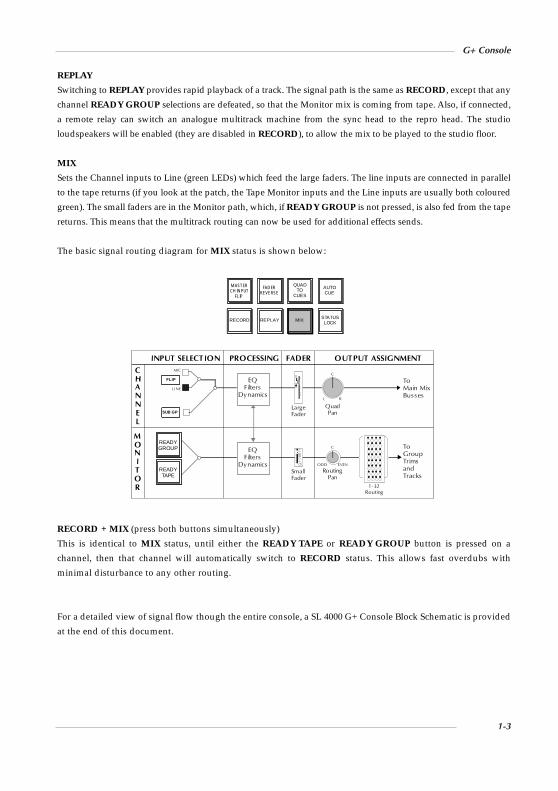
REPLAY
Switching to REPLAY provides rapid playback of a track. The signal path is the same as RECORD, except that any
channel READY GROUP selections are defeated, so that the Monitor mix is coming from tape. Also, if connected,
a remote relay can switch an analogue multitrack machine from the sync head to the repro head. The studio
loudspeakers will be enabled (they are disabled in RECORD), to allow the mix to be played to the studio floor.
MIX
Sets the Channel inputs to Line (green LEDs) which feed the large faders. The line inputs are connected in parallel
to the tape returns (if you look at the patch, the Tape Monitor inputs and the Line inputs are usually both coloured
green). The small faders are in the Monitor path, which, if READY GROUP is not pressed, is also fed from the tape
returns. This means that the multitrack routing can now be used for additional effects sends.
The basic signal routing diagram for MIX status is shown below:
RECORD + MIX (press both buttons simultaneously)
This is identical to MIX status, until either the READY TAPE or READY GROUP button is pressed on a
channel, then that channel will automatically switch to RECORD status. This allows fast overdubs with
minimal disturbance to any other routing.
For a detailed view of signal flow though the entire console, a SL 4000 G+ Console Block Schematic is provided
at the end of this document.
CHANNEL
MONITOR
INPUT SELECTION PROCESSING FADER OUTPUT ASSIGNMENT
EQFilters
DynamicsLINE
MIC
EQFilters
Dynamics
QuadPan
C
L R
ToMain MixBusses
M ASTERCH IN PUT
FL IP
FAD ERREVERSE
QUADTO
CUES
RECORD REPLAY MIX STATUSLOCK
READYTAPE
READYGROUP
FLIP
SUB GP
AUTOCUE
1-32Routing
RoutingPan
C
ODD EVEN
ToGroup TrimsandTracks
LargeFader
1 0
1 0
2 0
3 0
4 0
5 0
SmallFader
G+ Console
1-3

Input/Output Module
Channel Input Section
This section provides a transformerless microphone amplifier, featuring low noise
and high CMRR, with stepped, variable range of 70dB down to line level, a gain
control, and 48V phantom power supply switch.
An electronically balanced line amplifier with trim pot, providing high input
overload margin and balanced input impedances to both differential and common-
mode inputs. The Phase Reverse switch (Ø) operates on both inputs.
Channel input is globally defined by the selected Master Status, however, FLIP toggles input selection locally between
Mic and Line, with MASTER CHANNEL INPUT FLIP in the centre section reversing channel input selections across
the desk. Selection of SUBGP replaces the current channel input with that module’s group mix amp output, enabling
the creation of audio subgroups, with the Group Trim acting as a master level control.
The CHANNEL IN TO METERS button, in the centre section, facilitates viewing of the Channel Input levels,
overriding the bus/tape default.
See Appendix B for the Channel Input Amplifier specification.
Dynamics Section
This comprises a soft-knee Compressor/Limiter and Expander/Gate, which are
selectable to the Channel or Monitor signal path. For the Channel path, the
Dynamics can be switched pre (CH IN) or post (CH OUT) Equaliser. MON applies
the dynamics section to the Monitor path (post EQ if also selected).
Although the same gain change element is utilised for both Compressor/Limiter and
Expander/Gate, two dedicated LED displays are provided to indicate the activity in
each device. Automatic gain make-up, evaluated from the Ratio and Threshold settings,
is applied by the compressor to maintain a steady output level. The default compressor
attack time is programme sensitive, responding to the audio material’s wavefront.
The Gate default setting is actually that of an Expander, behaving in this
application as a gentle gate. Variable hysteresis is incorporated into the Threshold
circuitry, allowing the signal to decay below the opening level.
The dynamics Key Input/Sidechain can be sourced from the modules’ Monitor
path (select CH IN or CH OUT and MON simultaneously), or post filter signals.
Dynamics sections may be ganged using the LINK keys; whilst each channel
indicates its individual input activity, whichever channel whose processing is
working hardest will the dominant signal, driving all linked circuits.
See Appendix B for Dynamics specifications.
GATE
CHIN
CHOUT
MON
DYNAMICS to
EXPAND
LINK
DYNAMICS
COMPRESS
1
2
3 8
20
5
RATIO
RELEASE
THRESHOLD
pull RELEASEfor fast attack
+10 -20
+5
0 -10
-15
-5
.1 4
.15
.2 1
2
.4
F
THRESHOLD-30 +10
-25
-20 +4
+5
-12
0 40
5
10 30
35
20
RANGE
RELEASE.1 4
.15
.2 1
2
.4
F
20
14
10
6
3
0
-20 +20
FLIP
SUBGP
Ø
48v
LINE
MIC
+4 +7010
1622
2834 40
525864
G Series Shortform Guide
1-4

Equaliser Section
High Pass (18dB per octave) and Low Pass (12dB per octave) Filters are provided at the
top of this section. The Filters may be switched into the Dynamics section side chain to
afford simple de-essing etc., by the selection of FLT DYN SC (at the foot of the section).
The equaliser is a four band device, switchable to either signal path with the CH
and MON buttons respectively. Normally the Filters are switched into the same
path with these buttons, pre equaliser unless SPLIT is selected. SPLIT switches the
Filters to the Channel path pre input select and phase reverse switch.
Two different EQ cards are available. The standard G-Series parametric EQ
comprises variable bandwidth mid-range curves with adjustable Q (the bandwidth
decreases as the gain is increased), and shelving high and low bands, with LMF and
HMF range shift switches. See Appendix B for detailed EQ parameters.
The IN and PRE buttons control the Channel path Insert point. The insert is switchable
pre or pre equaliser with the PRE button. Selection of IN switches the Insert Return back
into the Channel signal path. Note that the Insert Send always carries the Channel signal
and may be used as an additional pre fader output if required.
Many signal processing routing arrangements are possible, using the Dynamics,
EQ, Filters, Insert and Dynamics Sidechain shared between the Channel and
Monitor paths. See diagrams in Appendix A for details.
Overload Indicator
The overload detection circuit monitors the Channel signal path at three different
points: Channel input, pre channel fader and pre channel fader. The overload LED
(fitted between the EQ and Cues sections) will indicate when the signal at any of
these points is within 4dB of clipping.
SPLIT
HMF x3
INSERT
IN
PRE
÷LMF 3
CHFLTDYNS/C
MON
EQUALISER to
FILTERS
HF
HMF
LMF
LF
OUT 350
20
70 200
300
120OUT 3
12
8 4
3.5
5
Hz
kHz
– +
– +
– +
– +
0
0
0
0
1.5 16
2
5 10
14
8
kHz
.6 7
.8
1.5 4.5
6
3
kHz
.2 2.5
.3
.8 1.5
2
1
kHz
30 450
50
100 300
200
Hz
3
2 1
.5
1.5
3
2 1
.5
1.5
G+ Console
1-5

Cue and Aux Sends
One stereo and four mono auxiliary sends are provided. These may be individually
sourced pre or post the small or large fader, according to selection of the
appropriate buttons.
The controls fulfil a dual purpose, firstly as Cue sends (Stereo, plus 1 and 2), capable of
receiving talkback injection, stereo echo return signals, and any external source added
from the centre section, for Headphone (Cans) and Studio Loudspeaker (SLS) feeds.
Alternatively, sends 1 to 4 may be used as echo sends or clean feeds to FX devices.
Each auxiliary bus has a master level control in the centre section, with a push-push
On/Off switch, and dedicated high and low pass filters. The bus outputs can be
viewed on dedicated meters, usually found above the patchbay.
Selecting MIX TO CUES (to the left of the Master Fader) replaces any existing cue
feeds with the consoles main output, providing a quick and simple way of
supplying the mix to headphones.
SuperCue
In Record Ready mode (see Monitor Input section below), hitting PRE on any
cue/auxiliary send assigned to the Monitor path (usually the large fader by
default) actuates the SuperCue system. This feeds the headphones an alternative
arrangement of inputs to those being monitored in the control room. See the G
Series Console Operator’s Manual for details.
Group Output Section
This comprises the Group mix amp, with its attenuating TRIM pot, plus the crucial
FLOAT and DIRECT buttons (see Routing Matrix section, Page 1-9). The behaviour
of this section is highly dependent on the console’s Master Status. The Group Trim
pot has an integral pull-push Solo Isolate switch.
Monitor Input Section
This section provides selection of inputs to the module’s Monitor path, together
with small fader input selection.
READY GROUP derives its input from the corresponding Group amp output,
allowing the signal being sent to tape (Multitrack Send) to be monitored (and
metered), whilst permitting the big red record switch to be enabled. READY TAPE,
monitors the multitrack returns until the machine is in record. Selecting READY
GROUP and READY TAPE together enables simultaneous monitoring of tape
send and return signals, allowing a previously recorded take and the new
performance to be monitored prior to a drop-in.
GROUP
FLOAT
DIRECT
INPUT
OUTPUT
0dB-30
10
5
READYTAPE
READYGROUP
24
pull for Solo Isolate
TRIM
from CHANNEL
PRE
SMALLFADER
3
PRE
SMALLFADER
4
PRE
SMALLFADER
2
PRE
SMALLFADER
1
PRE
SMALLFADER
STEREO
L R
C
CUES OVERLOAD
G Series Shortform Guide
1-6

Small Fader
Depending on the console’s Master Status, the small fader can control signals in the
Monitor path (Record Status) or the Channel path (Record and Fader Reverse).
During mixdown, the small fader may serve as an additional line input for any
signal patched into the Tape Monitor Input.
The ‘from CHANNEL’ INPUT and OUTPUT buttons change the small fader
source to channel signals as follows:
INPUT Pre signal processing but after Filters if SPLIT
OUTPUT Post large fader
INPUT + OUTPUT Pre signal processing, pre large fader
In Mix Status, signals picked up in this way may be used as extra Echo (FX) Sends
via the Routing Matrix.
The small fader SOLO button normally provides a destructive solo or AFL (After-
Fader Listen) function. The choice is made on a console-wide basis in the centre
section. The function of the CUT button should be self explanatory. Pre Monitor
fader auxiliary sends will not be cut by this function unless optionally set to do so
by an internal switch.
The green ‘to ROUTING’ LED below the fader confirms which fader is feeding the
multitrack routing busses. When lit, the small fader feeds these busses; when not
lit, the large fader is feeding the busses.
The Large Fader
The fader below each I/O module normally controls the module’s VCA. If the
console is fitted with SSL’s Ultimation™ automation system (see Section 2), this
fader will be motorised.
The large fader SOLO is switchable to provide a destructive solo or AFL function as
described previously for the small fader. Backstop PFL may be provided as an option.
The Status button and LEDs are associated with the G Series Computer and its
automated mix system (see Section 2).
60
INPUT
OUTPUT
SOLO
CUT
to ROUTING L R
10
5
0
5
10
20
30
∞
40
READYTAPE
READYGROUP
24
SOLO CUT
F
B
IN
C
from CHANNEL
G+ Console
1-7

VCA Control Groups
In addition to the console’s comprehensive patch-free audio subgroup facilities (see
the G Series Console Operator’s Manual for details) eight VCA control group faders
are provided in the centre section. Assignment of large faders to these control
groups is achieved by means of the thumbwheel switch beside each fader. The
control groups themselves are also fitted with thumbwheel selectors, to enable
(sensible) group to group assignments.
As well as groups 1-8, each thumbwheel has 0 (zero) and I (Independent) positions.
On non-Ultimation consoles, when selected to 0, fader levels may be varied by
±15dB using the VCA TRIM control in the centre section, enabling the overall level
of a mix to be quickly adjusted. Set to I, faders become independent of this control
and any other group selection, preventing faders being cut by the control group
SOLO buttons.
SOLO buttons on the control group faders work in a similar way to those on the
channels, by muting all other non-soloed control groups, and therefore the
channels assigned to them. Note that control group SOLO buttons cannot provide
an AFL function, except on G+ Special Edition consoles that feature the ‘True Group
Solo’ modification.
10
5
0
5
10
20
30
50
∞
group
trim
abs
status
40
0
alt
24
SSL
to ROUTING L R
SOLO CUT
G Series Shortform Guide
1-8
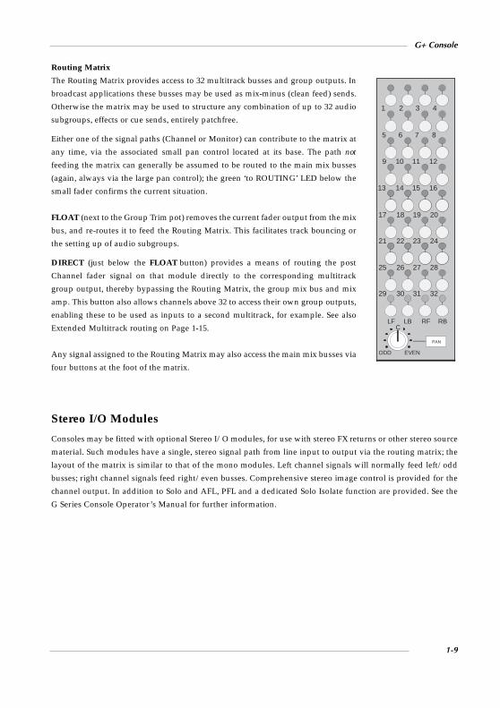
Routing Matrix
The Routing Matrix provides access to 32 multitrack busses and group outputs. In
broadcast applications these busses may be used as mix-minus (clean feed) sends.
Otherwise the matrix may be used to structure any combination of up to 32 audio
subgroups, effects or cue sends, entirely patchfree.
Either one of the signal paths (Channel or Monitor) can contribute to the matrix at
any time, via the associated small pan control located at its base. The path not
feeding the matrix can generally be assumed to be routed to the main mix busses
(again, always via the large pan control); the green ‘to ROUTING’ LED below the
small fader confirms the current situation.
FLOAT (next to the Group Trim pot) removes the current fader output from the mix
bus, and re-routes it to feed the Routing Matrix. This facilitates track bouncing or
the setting up of audio subgroups.
DIRECT (just below the FLOAT button) provides a means of routing the post
Channel fader signal on that module directly to the corresponding multitrack
group output, thereby bypassing the Routing Matrix, the group mix bus and mix
amp. This button also allows channels above 32 to access their own group outputs,
enabling these to be used as inputs to a second multitrack, for example. See also
Extended Multitrack routing on Page 1-15.
Any signal assigned to the Routing Matrix may also access the main mix busses via
four buttons at the foot of the matrix.
Stereo I/O Modules
Consoles may be fitted with optional Stereo I/O modules, for use with stereo FX returns or other stereo source
material. Such modules have a single, stereo signal path from line input to output via the routing matrix; the
layout of the matrix is similar to that of the mono modules. Left channel signals will normally feed left/odd
busses; right channel signals feed right/even busses. Comprehensive stereo image control is provided for the
channel output. In addition to Solo and AFL, PFL and a dedicated Solo Isolate function are provided. See the
G Series Console Operator’s Manual for further information.
C
PAN
ODD EVEN
LF LB RF RB
29 30 31 32
25 26 27 28
21 22 23 24
17 18 19 20
13 14 15 16
9 10 11 12
5 6 7 8
1 2 3 4
G+ Console
1-9

The Centre Section
The SL 4000 G+ centre section contains many master facilities, including the console’s master status selection,
main bus output, monitoring and metering controls, cue/aux send and echo return masters, talkback facilities,
a test oscillator and power rail indicators ( for the layout of centre section controls, see the foldout drawing at
the end of this guide).
Main Outputs
Channels assigned to the console’s main mix busses (LF, RF. LB, RB)
feed mix amps in the centre section. Main output control is via the
Master Fader (with accompanying AutoFade function) in conjunction
with the Quad Compressor (see right). This famous soft-knee
compressor has achieved unparalleled popularity in the world’s top
recording studios. With a little overpatching, the compressor may be
made available for use during tracking — access is via the Pre and
Post VCA Insert Sends and Returns provided on the patchbay.
The compressor is also available from SSL in a 1U rack-mounting
Logic FX package.
The main bus outputs, plus derived stereo and mono outputs, are
normalled via the patchbay and distributed to machine inputs via the
console’s connector panel.
Metering
Metering facilities will vary according to specification. As standard, the console is equipped with moving-coil
VU meters for each I/O module, and eight mechanical VU meters (alternatively PPMs, with a choice of scales)
above the centre section, dedicated to LF, RF, LB, RB, Left, Right, Mono and Phase for the main busses. A stereo
audio phasescope, metering the main Left and Right outputs, is also provided as standard. Meters for the
Auxiliary Sends and Studio Loudspeaker outputs are fitted above the patchbay.
According to selections made on the ‘QUAD METERS’ buttons, the meters can be selected to meter the DESK
OUTPUT, the EXTERNAL SOURCE matrix or whichever is being monitored — FOLLOW MONITOR.
Optionally, mechanical PPM or 250-segment Plasma Bargraph meters may have been provided for the channels
and/or main outputs. Bargraph meters are switchable between VU and PPM scale characteristics and also
provide a 3rd octave, 15 band, stereo, spectrum analysis display. A group of nine buttons controls these
functions from the centre section.
AAAA
AAAA
AAAA
7.5
AAAA
+15
0
AAAA
-15 +15THRESHOLD
ATTACK-mS
RATIO
MAKE-UP
RELEASE-S
2 4 10
.1
.3 .6 1.2
Auto
0
IN
QUAD COMPRESSOR
.1
.31 3
10
30
AAAAAAA
0
48 12
16
20
dBCOMPRESSION
G Series Shortform Guide
1-10

Monitoring
Comprehensive monitoring facilities are provide to the lower right of the
centre section. For stereo applications, the control room loudspeakers
normally monitor the LF and RF output busses in STEREO mode.
Alternatively all four busses may be monitored on a pair of loudspeakers
by selecting STEREO and QUAD simultaneously. On consoles
configured for surround mixing, the QUAD button is redesignated LCRS.
In either configuration, MONO provides a mixed feed of all four busses.
If EXTERNAL TO MONITORS is selected, any source in the matrix
above (CUE STEREO to 4 TRK 2) may be monitored. The patchbay
provides inputs for up to five stereo and three 4-channel sources.
The monitor output may be dimmed, when the DIM button is pressed,
by a level set on the associated DIM level control. Final monitor output
level is set on the large rotary MONITOR switch, unless MINI 1 or MINI
2 have been selected, in which case level is set on the rotary MINI LS
control. Monitor outputs may be cut with the appropriate ‘MONITOR
CUTS’ button above the Quad Compressor.
Studio Loudspeakers
The vertical row of buttons to the left of the EXTERNAL TO MONITOR
source selector presents a number of sources (notably including QUAD
BUS), that may be fed to a pair of studio loudspeakers on selection of
EXTERNAL TO STUDIO. Level to the speakers is controlled by the SLS
pot to the left. This output may have talkback injected (see above). SLS
output meters are provided above the patchbay.
Note that, to prevent howlround, selection of EXTERNAL TO
STUDIO is prohibited in Record Status and Status Lock (see Page
1-13), though this can be overriden by an internal link.
MINI LS
54
321
0
678
910
MINI1
MINI2
DIM
CUT
DIMlevel
MONO
STEREO
MONITORMATRIX
MONITORS
QUAD
60
40
35
30
25
20
15
10
5
0
∞
MONITOR
5
01
2
3
46
78
9
1011
AAAAAA
60
40
35
30
25
20
15
10
5
0
∞
EXTERNALTO
STUDIO
EXTERNALTO
MONITORS
DISC
4 TRK1
QUADBUS
4 TRK1
4 TRK2
DISC
G+ Console
1-11

Solo/AFL
The SOLO buttons on each channel normally provide a destructive solo-in-place function. Selecting the AFL
button in the centre section forces the SOLO buttons to provide an After Fader Listen function. AFL signals
replace the default feed to the monitors at a level set by the pot above the AFL button. AFL is automatically
selected when Status Lock is enabled (see Page 1-13).
Large and small fader solo cut busses can be linked to act simultaneously by selecting SOLO LINK (fitted to
the upper right of the computer keyboard panel). This is useful when sources to the mix are feeding the inputs
to both Channel and Monitor signal paths.
Cue/Auxiliary Sends and Echo Returns
The G+ auxiliary sends system provides one stereo and four mono busses fed from controls on the I/O
modules. Master level controls for these busses (each with a push/push On/Off switch) plus LF and HF
equalisation, are provided near the top the centre section.
The sends may be used as clean feeds, FX device feeds, or as headphone outputs. Clean feeds and feeds to FX
devices should be patched from the ‘ECHO SEND’ or ‘LOCAL AUX SEND’ (see below) outputs on the
patchbay, or connected via the console connector panel. Six meters are fitted above the patchbay to display the
output levels.
The system provides three stereo outputs (Cue Sends) for use as headphone feeds. Cue Sends L and R are fed
from the stereo auxiliary bus. Cue Sends 1L and 1R, and 2L and 2R are derived from the mono auxiliary busses
1 and 2. Insert points are provided on the patchbay. Any source selected on the External to Studio selectors may
be fed in stereo to the headphones, simply by turning up the CUES pot next to the SLS pot. If QUAD TO CUES
(to the left of the Master Fader) is selected, any existing cue feeds are replaced with the console’s main output.
This provides a quick and simple way of feeding the main mix to headphones.
Two sets of master send controls are provided; normally all sends pass via a single set of controls at the top of
the main centre section module. SPLIT buttons on the LOCAL AUX SENDS (fitted to the left of that panel)
enable sends from modules to the left of the centre section to be isolated from those to the right; these feed a
set of dedicated outputs on the patchbay.
Four Stereo Echo Returns, fitted below the auxiliary send master controls, may be used to return FX device
outputs or any other stereo or mono source to the main mix busses via dedicated pan and level controls. Each
return is fitted with AFL and CUT buttons, and routing switches to enable the return source to be fed back onto
the Cue/Aux busses.
G Series Shortform Guide
1-12

Talkback
A group of nine ‘COMMUNICATIONS’ buttons are provided at the foot of the module. Along with the
microphone fitted between the CUES and SLS pots, and the level controls at the top of the centre section, these
provide talkback to the three Cue outputs, individually or simultaneously. OMNI talks to all Cues, the studio
loudspeakers, and supplies a slate talkback (with 30Hz tone) to the multitrack groups and main desk outputs.
An externally connected listen mic (return talkback) may be fed to the Mini loudspeakers and/or the
multitrack groups and main desk outputs. The two Listen Mic inputs are fitted with a single built-in
compressor; a post-compressor output, that can provide an interesting effect when recording guitars, for
example, is supplied on the patchbay.
If the AUTOCUE function is selected, the normally momentary CUES talkback button will latch on. The button
remains latched until any machine interfaced to the master tape remote buttons in the centre section goes into
Play (optionally, Record). The button then relatches as soon as the machine enters Stop, Fast Forward or
Rewind, thus enabling immediate communication with the headphones. If used without due caution, this may
lead to severe embarrassment!
A RED LIGHT button provides a isolated contact closure for interface to an external relay; the circuit can be
optionally driven from tape machine play or record tallies.
Status Lock
STATUS LOCK is an extremely useful facility situated in the group of Master Status buttons. On selection, it
inhibits the following functions, which could be dangerous if activated during recording, or in a broadcast
on-air situation:
Status buttons - Record, Replay, Mix, Fader Reverse, and Master Channel Input Flip
Oscillator On
Omni Talkback
Listen Mic to Tape
AutoCue
Solo in Place (AFL automatically selected)
Studio Loudspeaker Outputs
Optionally, the Red Light may be switched on in Status Lock.
Oscillator
The GROUPS button feeds tone, via the slate bus, to the 32 multitrack Group Outputs. QUAD BUS feeds tone
to the main mix bus outputs. The cal. position on the level control may be preset to local requirements. House
tone, or an external signal generator, may be injected onto the slate bus via the patchbay. The oscillator feed to
bus outputs is inhibited in Status Lock (see above).
Power rail indicators are fitted above the oscillator. If any of these is not lit, seek technical help!
G+ Console
1-13
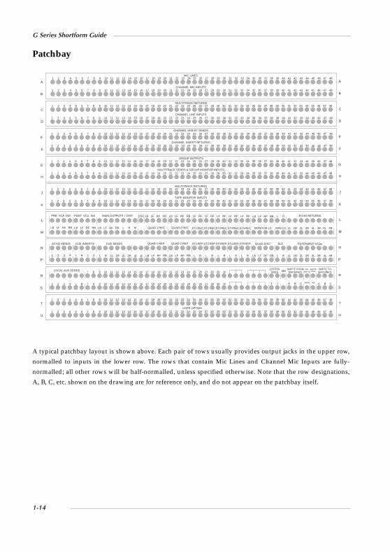
Patchbay
A typical patchbay layout is shown above. Each pair of rows usually provides output jacks in the upper row,
normalled to inputs in the lower row. The rows that contain Mic Lines and Channel Mic Inputs are fully-
normalled; all other rows will be half-normalled, unless specified otherwise. Note that the row designations,
A, B, C, etc. shown on the drawing are for reference only, and do not appear on the patchbay itself.
MIC LINES
CHANNEL MIC INPUTS
MULTITRACK RETURNS
CHANNEL LINE INPUTS
CHANNEL INSERT SENDS
CHANNEL INSERT RETURNS
GROUP OUTPUTS
MULTITRACK SENDS & GROUP MONITOR INPUTS
MULTITRACK RETURNS
TAPE MONITOR INPUTS
A
B
C
D
E
F
G
H
J
K
A
B
C
D
E
F
G
H
J
K
1 2 3 4 5 6 7 8 9 10 11 12 13 14 15 1716 18 19 20 21 22 23 24 25 26 27 28 29 30 31 32 33 34 35 36 37 38 39 40 41 42 43 44 45 46 47 48
1 2 3 4 5 6 7 8 9 10 11 12 13 14 15 1716 18 19 20 21 22 23 24 25 26 27 28 29 30 31 32 33 34 35 36 37 38 39 40 41 42 43 44 45 46 47 48
ECHO SENDS
1 2 3 4
CUE INSERTS
L R 1 2
QUAD 1 REP QUAD 2 REP
LB LF RF RB LB LF RF RB
ST1 REP ST2 REP ST3 REP ST4 REP ST5 REP
L R L R L R L R L R
QUAD DISC
LB LF RF RB
SLS
L R
PATCHABLE VCAs
1L 1R 2L 2R 3L 3R 4L 4R
CUE SENDS
Ø ØL R 1L 1R 2L 2R
N
P
N
P
PRE VCA INS POST VCA INS MAIN OUTPUTS + DIST OSC
LB LF RF RB L R M QUAD 1 REC QUAD 2 REC ST1RECLB LF RF RB LB LF RF RB ST2RECST3REC ST4RECST5REC
LF RF LF RF LF RF LF RF LF RFLB LF RF RB LB LF RF RB LB LF RF RB
MONITOR LS MINI LS
L R ECHO RETURNS
1L 1R 2L 2R 3L 3R 4L 4R
L
M
L
M
SMPTE FROMMACHINES
A B C
SMPTESMPTE SMPTE TO
MACHINES
READ INS A B C
LOCAL AUX SENDS
1 2 3 4 L R
LISTENMICS MD
1 2
R
S
T
U
R
S
T
U
SSLGEN
1 2 3 4 5 6 7 8 9 10 11 12 13 14 15 1716 18 19 20 21 22 23 24 25 26 27 28 29 30 31 32 33 34 35 36 37 38 39 40 41 42 43 44 45 46 47 48
1 2 3 4 5 6 7 8 9 10 11 12 13 14 15 1716 18 19 20 21 22 23 24 25 26 27 28 29 30 31 32 33 34 35 36 37 38 39 40 41 42 43 44 45 46 47 48
7 8 9 10 11 12 13 14 15 1716 18 19 20 21 22 23 24 25 26 27 28 29 30
7 8 9 10 11 12 13 14 15 1716 18 19 20 21 22 23 24 25 26 27 28 29 30
1 2 3 4 5 6 7 8 9 10 11 12 13 14 15 1716 18 19 20 21 22 23 24 25 26 27 28 29 30 31 32 33 34 35 36 37 38 39 40 41 42 43 44 45 46 47 48
1 2 3 4 5 6 7 8 9 10 11 12 13 14 15 1716 18 19 20 21 22 23 24 25 26 27 28 29 30 31 32 33 34 35 36 37 38 39 40 41 42 43 44 45 46 47 48
1 2 3 4 5 6 7 8 9 10 11 12 13 14 15 1716 18 19 20 21 22 23 24 25 26 27 28 29 30 31 32 33 34 35 36 37 38 39 40 41 42 43 44 45 46 47 48
1 2 3 4 5 6 7 8 9 10 11 12 13 14 15 1716 18 19 20 21 22 23 24 25 26 27 28 29 30 31 32 33 34 35 36 37 38 39 40 41 42 43 44 45 46 47 48
1 2 3 4 5 6 7 8 9 10 11 12 13 14 15 1716 18 19 20 21 22 23 24 25 26 27 28 29 30 31 32 33 34 35 36 37 38 39 40 41 42 43 44 45 46 47 48
1 2 3 4 5 6 7 8 9 10 11 12 13 14 15 1716 18 19 20 21 22 23 24 25 26 27 28 29 30 31 32 33 34 35 36 37 38 39 40 41 42 43 44 45 46 47 48
1 2 3 4 5 6 7 8 9 10 11 12 13 14 15 1716 18 19 20 21 22 23 24 25 26 27 28 29 30 31 32 33 34 35 36 37 38 39 40 41 42 43 44 45 46 47 48
1 2 3 4 5 6 7 8 9 10 11 12 13 14 15 1716 18 19 20 21 22 23 24 25 26 27 28 29 30 31 32 33 34 35 36 37 38 39 40 41 42 43 44 45 46 47 48
USER OPTION
G Series Shortform Guide
1-14

Options
Custom Switch Functions
According to customer requirements, a number of standard SSL options may be implemented on the centre
section master module, or to the right of the keyboard panel, as indicated by suitably engraved button caps.
Common options include Solo Isolate and/or Fader Reverse Inhibit on specific bays, or even the right hand
side of the console, enabling split-console style operation.
Patchable Stereo VCAs
Four automated faders to control stereo VCAs may be installed under the centre section master module.
Accessed via the patchbay, these can be used to control and automate echo returns, auxiliary sends or even a
pair of main bus outputs. Each fader has a CUT and AFL function.
Extended Multitrack Routing
Consoles fitted with 48 or more I/O modules are supplied as standard with ‘Group Cross Normalling’. This
enables Groups 1-24 to feed Group Outputs 1-24 and 25-48 simultaneously, and thus provides full access to a
48-track machine from the Routing Matrix.
For additional flexibility, consoles may be fitted with Group Cross Linking; this also provides access to 48 tracks
but in a different manner: multitrack busses 1-24 feed the group mix amps (and trims) in modules 1 and 25, (49,
65,...) 2 and 26 (50, 66, ...) etc, thereby providing most of the benefits of conventional 48 track routing.
User-selectable Options (via internal switches and links), include:
Record tally — selectable to operate on track record or track readied.
Track record — selectable to operate in record status only.
Group and Tape monitor inputs — in ‘SuperCue’ mode can be set to give unity gain or a 3dB drop (default) on
each input whilst summed.
Channel Insert — can be set to follow EQ.
Channel VCA solo isolate — may not be enabled when SUBGP is selected.
G+ Console
1-15

Appendix A — Signal Processor Routing
Here are just a few of the many routing possibilities that are available for signal processing on the G+
Input/Output module:
G Series Shortform Guide
1-16
AAAAAAAAAAAAAAAAAAAAAAAAAAAAAAAAAAAA
CHANNEL
MONITOR
SmallFaderAA
LargeFader
AAA
10
5
0
5
10
20
30
40
50
ALINE
M IC
AFLIP
SUB GP
TAPE
G RO UPEQUALISER to
PRE
IN
IN
PRE
DYNAMICS to
CHOUT
AACHIN
MON
AA
A
FLTDYNS-C
CH
A
MON
SPLIT
FILTERS INSERT
IN PRE
INSERT
DYNS-C
CH
AAAAAAAAAAAAAAAAAAAAAAAAAAAAAAAAAAAAAAAAAAAAA
CHANNEL
MONITOR
SmallFader
AA
LargeFaderAAA10
5
0
5
10
20
30
40
50ALINE
M ICAFLIP
SUB GP
TAPE
G RO UPEQUALISER toPRE
IN
IN
PRE
DYNAMICS to
CHOUT
A
CHIN
MON
A
A
FLTDYNS-C
CH MON
SPLIT
FILTERS INSERT
IN PRE
INSERT
DYNS-C
CH
AAAAAAAAAAAAAAAAAAAAAAAAAAAAAAAAAAAAAAAAAAAAA
CHANNEL
MONITOR
SmallFaderAAA
LargeFaderAAA
10
5
0
5
10
20
30
40
50
ALINE
M IC
AA
FLIP
SUB GP
TAPE
G RO UPEQUALISER to
INSERT
PRE
IN
IN
PRE
DYNAMICS to
A
CHOUT
CHIN
MON
A
AA
FLTDYNS-C
CH
AA
MON
SPLIT
FILTERS INSERT
IN PRE
INSERT
DYNS-C
CH
AAAAAAAAAAAAAAAAAAAAAAAAAAAAAAAAAAAA
CHANNEL
MONITOR
SmallFaderAA
LargeFader
AA
10
5
0
5
10
20
30
4050
ALINE
M IC
AFLIP
SUB GP
TAPE
G RO UPEQUALISER to
PRE
IN
IN
PRE
DYNAMICS to
CHOUT
AACHIN
MON
AA
FLTDYNS-C
CH
A
MON
SPLIT
FILTERS INSERT
IN PRE
INSERT
DYNS-C
CH
SIGNAL PROCESSOR PATHPROCESSOR SWITCHING

G+ Console
1-17
AAAAAAAAAAAAAAAAAAAAAAAAAAAAAAAAAAAA
CHANNEL
MONITOR
SmallFaderAA
LargeFader
AAA
10
5
0
5
10
20
30
40
50
ALINE
M IC
AFLIP
SUB GP
TAPE
G RO UPEQUALISER toPRE
IN
IN
PRE
DYNAMICS to
ACH
OUTCHIN
MON
A
FLTDYNS-C
CH MON
SPLIT
FILTERS INSERT
IN PRE
INSERT
MON
DYNS-C
CH
AAAAAAAAAAAAAAAAAAAAAAAAAAAAAAAAAAAAAAAAAAAAA
CHANNEL
MONITOR
SmallFader
AA
LargeFaderAAA10
5
0
5
10
20
30
4050A
LINE
M ICAFLIP
SUB GP
TAPE
G RO UPEQUALISER to
PRE
IN
IN
PRE
DYNAMICS to
A
CHOUT
CHIN
MON
A
FLTDYNS-C
CH
AMON
SPLIT
FILTERS INSERT
IN PRE
INSERT
DYNS-C
CH
AAAAAAAAAAAAAAAAAAAAAAAAAAAAAAAAAAAAAAAAAAAAA
CHANNEL
MONITOR
SmallFaderAAA
LargeFaderAAA
10
5
0
5
10
20
30
40
50
ALINE
M IC
AA
FLIP
SUB GP
TAPE
G RO UPEQUALISER to
INSERT
PRE
IN
IN
PRE
DYNAMICS to
CHOUT
CHIN
MON
A
FLTDYNS-C
CH
AA
MON
SPLIT
FILTERS INSERT
IN PRE
INSERT
DYNS-C
CH
AAAAAAAAAAAAAAAAAAAAAAAAAAAAAAAAAAAA
CHANNEL
MONITOR
SmallFaderAA
LargeFader
AA10
5
0
5
10
20
30
40
50
ALINE
M IC
AFLIP
SUB GP
TAPE
G RO UPEQUALISER to
INSERT
PRE
IN
IN
PRE
DYNAMICS to
AA
CHOUT
CHIN
MON
FLTDYNS-C
CH
A
MON
SPLIT
FILTERS INSERT
IN PRE
INSERT
MON
DYNS-C
CH
SIGNAL PROCESSOR PATHPROCESSOR SWITCHING

Appendix B — 611G I/O Module Specifications
Microphone Amplifier (82E291)
Gain: Variable from +4dB to +70dB in 6dB steps
Input Impedance: 1.54kΩHeadroom: > +24dBu @ +4dB gain, at onset of clipping
> +27dB @ all other gain settings
Frequency Response: +0.0dB/-0.4dB from20Hz to 20kHz
Equivalent Input Noise: < -95dBu @ minimum gain
< -127dBu @ maximum gain
Line Amplifier (82E291)
Gain: -20dB to +20dB continuously variable with detent at unity gain
Input Impedance: > 30kΩ Balanced
> 20kΩ Unbalanced
Headroom: > +26.5dB at onset of clipping
Frequency Response: +0.0dB/-0.3dB from 20 Hz to 20 kHz
Equivalent Input Noise: < -95dBu
Dynamics Section
Compressor/Limiter
Ratio/Slope: Variable from 1 to infinity (limit)
Threshold: Variable from +10dB to -20dB
Attack Time: Normally auto-sensing, switchable to 1ms
Release: Variable from 0.1 to 4 seconds
Expander/Gate
Range: Variable from 0 to 40dB
Threshold: Variable from -30dB to +10dB
Attack time: Normally auto-sensing, switchable to 1ms
Release: Variable from 0.1 to 4 seconds
G Series Shortform Guide
1-18

G-Series Four Band Equaliser (82E292)
Two bands shelving with slope enhancement to increase selectivity; two bands wide ranging parametric with
action over a frequency band that varies with gain (variable ‘Q’ with gain). High and low pass filters also
provided with filter out switching.
Mid Bands
Freq Ranges HMF: 610Hz to 6.2kHz
or 1.8kHz to 18kHz switchable with HMF x3 button
LMF: 200Hz to 2.1kHz
or 50Hz to 500Hz switchable with LMF x3 button
Gain range > ±20dB
‘Q’ 0.5 to 3 (may also vary with gain)
Shelving Bands
Freq Range HF: 2kHz to 16kHz
LF: 30Hz to 450Hz
Gain Range ±17dB
Headroom > +26.0 dBu at onset of clipping
Noise < -86dBu
‘Classic’ E-Series Four Band Equaliser (82E242)
Two bands switchable bell/shelving; two bands parametric with action over a constant frequency band at all
gains (constant ‘Q’ with gain). High and low pass filtering with ‘filter out’ switch.
Mid Bands
Freq Ranges HMF: 600Hz to 7kHz
LMF: 200Hz to 2.5kHz
Gain Range Q @ 3: ±18dB
Q @ 0.5: ±15dB
‘Q’ 0.5 to 3
High and Low Bands
Freq Range HF: 1.5kHz to 16kHz
LF: 30Hz to 450Hz
Gain Range Bell: ±18dB
Shelving: ±16.5dB
Headroom > +26.0 dBu at onset of clipping
Noise < -82dBu
G+ Console
1-19

Filters (82E292 and 82E242)
Freq Ranges High Pass: 15Hz to 350Hz (-3dB point)
Low Pass: 3kHz to 20kHz (-3dB point)
Slopes High Pass: 18dB/Octave
Low Pass: 12dB/Octave
More detailed information may be found in the G+ Console Performance Specification.
Contact your local SSL representative to obtain a copy.
G Series Shortform Guide
1-20

G Series Computer
Introduction
The G Series computer is a logical and relatively simple command-based processor that allows the operator to
work with minimum distraction. It is internationally popular, and as such, a grasp of the fundamental
processes should open many studio doors for the competent operator.
In this guide, the dedicated command keys such as LIST, GOTO, PLAY etc. are shown in bold uppercase
letters (on-screen messages and console buttons are similarly indicated). QWERTY keyboard entered
commands such as LABEL, BEGIN etc. are in plain uppercase. User entries like timecodes, Cue names, Mix
names etc. are shown in parenthesis (name). Spaces are indicated by an underscore _. the EXECUTE key is
indicated as [EX]. For example:
GOTO CUE (name) [EX]
The four basic functions of a G Series Computer system are:
• Project data management (‘housekeeping’): Information relating to each session, such as Track Lists, Cues,
Total Recall Setups, Mixes, Notes, etc., can be created, displayed and stored.
• External machine transport control: Employing data from the session lists: locating, cueing, cycling, and the
rehearsal and execution of programmed drop-ins (minimising destructive errors).
• Total Recall (TR) — if fitted: The position of every knob and switch on each I/O module is stored, together
with fader positions and VCA group assignments. These settings can later be recalled to reset any
TR-equipped G/E Series console, anywhere in the world.
• Automated mixing: Extensive dynamic fader and mute automation facilitates the production, editing and
manipulation of large and complex mixes, on and off-line. Mixes can be joined, and data copied between
channels, from point to point in time, if required.
UltimationG Series automation can be supplemented by the Ultimation moving fader system which, by incorporating a
dual signal path circuit, combines the positional feedback of moving faders with the trim control of VCAs, all
within the familiar framework of G Series software. The fader motors may be turned on or off according to
taste; with motors on, the audio path is through the faders themselves, bypassing the VCAs.
G Series Command ReferenceA list of all the most commonly used computer commands is provided at the end of this section. The list is
based on the G Series Computer Reference Card, a handy pocket-sized guide that may also be downloaded
from our web site.
G Series Computer
2-1

Timecode
To synchronise automation data with the audio source, timecode (LTC) must be fed to the computer’s timecode
reader from the master audio machine. Two timecode formats, SMPTE (30fps or 29.97 drop frame) and EBU (25
fps), can be read from a striped track on traditional multitrack tape machines, or taken from the built-in
timecode track/output on digital devices; the reader may also handle 24fps (FILM) timecode. The reader input
is designated READ on the SSL patchbay.
Using the ‘Setup’ menu, the computer must be set to receive the required standard. Type:
SETUP [EX]
Y [EX]
S [EX] (this opens the ‘Session’ menu page)
Set Timecode frames per second to 24, 25 or 30. Use 30 for 29.97 non drop frame; if the timecode is 29.97 drop
frame select 30 and set Using drop frame? to YES.
Press END repeatedly to exit the menus.
The computer reads timecode whenever the transport is in forward motion at play speed, and displays the
value on a location counter; when shuttling at high speed, the computer automatically interrogates the
machine's tach pulses. On returning to standard forward motion, the computer checks the timecode and
updates it's clock to compensate for any slippage, if necessary.
Times are entered in the following format: Hours:Minutes:Seconds.Frames (eg. 12:34:56.12).
Abbreviated entries, made by omitting leading zeros and colons, are recognised by the system. For example:
.18 for 18 frames only
34. for 0 minutes 34 seconds 0 frames
4: for 4 minutes 0 seconds 0 frames
4:: for 4 hours 0 minutes 0 seconds 0 frames
An example of a short locate command would be GOTO 4:34 [EX]
When valid timecode is being received by the system, its position will be shown in the top right of the screen.
Beneath it should be a solid indication showing EBU, SMPTE, DF TC or FILM.. Any errors are shown by the
following indications:
Flashing SMPTE, EBU, DF TC or FILM: System is incorrectly set for this type of timecode
Flashing smpte, ebu, df tc or film: System must be reset to this type of timecode in the Setup menu
SMPTE?, EBU?, DF TC? or FILM?: Incorrect speed/Tach rate. Wrong master machine in Setup menu
SMPTE*, EBU*, DF TC* or FILM* No tach
G Series Shortform Guide
2-2

Striping a Tape
The G Series Computer has an integral timecode generator. However, where audio material on one machine is
to be synchronised with another, a video machine for example, all elements of the system must be locked to the
same sync source, and any recorded timecode must be provided by a LTC generator locked to the same sync
source.
In isolated circumstances, eg. where a multitrack tape is to stay within the facility, the SSL generator can be
activated by typing STRIPE [EX] and following the on-screen prompts. The timecode generated is dependent
upon the frame rate set in the ‘Session’ menu (see opposite).The generator output is available on the patchbay
under SMPTE GEN.
Data Storage
The G Series Computer uses a dual 3.5" floppy disk drive unit, located in the processor rack, designed to use
HD (High Density, 1.44MB) disks. The system software is stored on the ‘Program Disk’, which is loaded into
the left-hand P drive. Session information is stored on the ‘Reel Disk’ in the right-hand R drive. A single floppy
disk represents a ‘Reel’ (traditionally of tape), as against the earlier Bernoulli data cartridges which could be
subdivided into a number of different Reels.
Floppy disks must be formatted prior to use:
Place a disk into the Reel (R) drive, type FORMAT [EX], and follow the on-screen instructions. Press M for Mini
Floppy, followed by R for the Reel Disk. After the warnings and prompts, formatting will begin; this takes
about one minute. When completed, type LABEL [EX] to initialise the disk. This will produce a blank ‘List’
page, ready for use (see over the page).
G Series Computer
2-3
DATA CARTRIDGE
REELREEL REEL DISC
TITLE TITLE TITLE TITLE TITLE TITLE TITLE
etc
CUES TRACKS NOTES TR SETUPS MIXES EVENTS
etc

The information on this page (which may be called up at
any time by entering LIST [EX]), is for operator reference
only, except the tape speed and sample rate. The tape speed
must be set correctly to allow the computer to correctly
calculate tach pulses when a tape is spooling; for example,
to set the tape speed for 30ips type SP_30 [EX].
To change any other information on this page, type the
first two letters of the required field (except artist which
must be ART_), add a space and then the desired text.
For example: to enter the artist as ‘BETTY SWANK’, type
ART_BETTY SWANK [EX]
To enter the client as ‘T & A RECORDS’, type CL_T & A
RECORDS [EX]. Should you wish to preserve the names for all future Reel Disks as a default, type ALTER [EX].
To create TITLEs see below under Project Management.
Computer Control
The computer is controlled from a panel located in the centre of the console (see drawing provided at the end
of this guide). At the bottom right of this panel are five computer status buttons: MIX ON-OFF, FADER
STATUS, LARGE-SMALL, TAPE ENABLE, and RECORD ENABLE. To the left of these are the master
transport remotes, for manual control of the multitrack. The TAPE ENABLE button enables the computer to
control an external (tape) machine.
Communication with the computer is generally made via the lower dedicated command keyboard (LIST,
GOTO, PLAY etc.). These commands cannot be duplicated on the QWERTY keyboard. Command keys are
used to form simple English phrases in a basic command-line instruction. The G Series Computer allows
abbreviations, thereby eliminating numerous keystrokes, and interprets keys according to the context in which
they are used. Furthermore, the system prompts the engineer through the less common procedures and, should
a mistake be made, the computer will respond with the message I don’t understand, (adding the assistant’s
name from List page).
The upper alphanumeric keyboard is provided for the entry of specific words, especially names not found on
the dedicated keyboard. The function keys located above are commonly used to store frequently entered, or
long command lines. The dedicated numeric keypad is for the entry of timecodes and numbered locate points.
All command entries must be concluded by pressing the EXECUTE key; this informs the computer that the
command line has been completed, and the command should now be performed. To escape from any
command, or abort any command proceeding and delete the last command given, press the CANCEL key (note
that CANCEL does not need to be followed by EXECUTE, and is not detected when using the REPEAT key).
G Series Shortform Guide
2-4
59:28.22
* * Solid State Logic * *7:42 pm 24 OCT 2002
reel : BETTY SWANK drive B
4046 sectorcreated 24 OCT 2002
artist : BETTY SWANK client : T & A RECORDSproducer : JUSTIN CASEengineer : MARK TIMEassistant : ERIC RACE
eq : AESnr : SRspeed : 30 sample rate :
####
List

Project Management
There are a number of different lists in which details about the session are stored; the primary one of these is
the LIST [EX] page which stores basic project information, including the tape speed and timecode offset
settings (see opposite). All information relating to cues, mixes and setups (Total Recall) is stored under named
‘Titles’. A Title usually represents a song, or section of a recording, within a project.
The Title List is called up by entering LIST TITLE [EX]. It shows the names of all the titles (songs or sections),
complete with start (From) and end (To) times. This data is built up and stored on the Reel disk over the course
of initial tracking sessions.
Creating a New Title
Cue the machine to the beginning of the song or take
(having previously devised a source of timecode). Enter
NAME TITLE (song title) FROM HERE [EX], and the
TITLE page will be automatically displayed. Play or spool
the machine, and at the end of the song or take, enter
TITLE TO HERE [EX], causing the end (To) time to
appear in the list. You can change the To and From times
later by entering TITLE FROM (or TO) (time) [EX].
Your new TITLE will be displayed with From and To
times (as shown right).
Current Item
Notice that the new Title has a square cursor next to it. This means it is the current item. Whenever an item in
a list is stored, named or specified (as the subject of a command, except COPY) it becomes the current item,
until any other item from the same list is chosen. IF you enter a command line without a given name, the
computer will automatically choose the current item. For example, if the command PLAY TITLE [EX] is
entered, the computer will locate and play the Title with the cursor next to it. The same principle extends to all
other lists within that Title, such the Cue List, the Mix List, etc.
To select a different Title, Cue, Mix, etc. and make it current, issue a command including its name, eg. GOTO
TITLE (name) [EX]. To save time, and when working with any list, you can enter just the initial letter of a name.
In the example above, there are two Titles: ‘Groove That Tube’ and ‘Fast Muzak’. To select the latter Title,
GOTO TITLE F [EX] would be sufficient. Should you have two or more list items beginning with the same
letter, add sequential letters to the command until the computer can differentiate.
G Series Computer
2-5
0:49.06
###
List title
client: T & A RECORDS reel: BETTY SWANK
title from to
GROOVE THAT TUBEFAST MUZAK
0:49.067:02.05
6:12.0511:21.17

Basic Autolocator Functions
Ensure TAPE ENABLE is pressed for all control via computer locate functions.
GOTO will locate to a specified timecode value or TITLE, CUE etc and stop, eg. GOTO CUE INTRO [EX]
PLAY will locate to the specified item and play, eg, PLAY MIX 1 [EX]
HERE [EX] creates a volatile location point in memory. You can return to the mark using either GOTO [EX] or
PLAY [EX]
To hear a track several times over, enter CYCLE TITLE [EX]; the multitrack will roll to the beginning of the
Title, play it, and rewind, repeating the procedure until instructed to do otherwise.
More elaborate commands can be composed, always in common-sense English, such as: CYCLE TITLE FROM
HERE [EX] which plays from the current location to the end of the Title, then rewinds to the current location
and repeats the sequence until told to stop.
Cues
A Cue List enables the division of Titles into subsections (verses, choruses, etc) and the identification of
locations such as instrumental breaks.
To list the Cues (if any have been created): LIST CUE [EX]
Cue points can be generated in two ways: enter NAME CUE (name) [EX], or, to save keystrokes, the NAME
key need not be used — CUE (name) [EX] will do the same. If you use just CUE [EX], the Cues will be created
with a computer generated 1*, 2*, 3* etc., name. The timecode reference of a Cue will be the instant the [EX]
key is pressed. Using the REPEAT key enables Cues to be rapidly produced on-the-fly.
Cues can be renamed thus: CUE (name) NAME (new name) [EX]
Useful Tip: If you name the Cues VERSE 1, VERSE 2 etc, then the computer will need V_1, V_2 etc. to
differentiate between them, as in PLAY CUE V_1 [EX]. But, if you name them 1 VERSE, 2 VERSE etc. then the
computer only needs to differentiate between the numbers, as in PLAY CUE 1 [EX].
A Cue can be shifted in time: CUE (name) TO (time) [EX]. A block of Cues can be shifted in time: REVISE CUE
FROM (time 1) TO (time 2) TO (time 3) [EX]. This can be useful if you are recording another version of a track
but using the same Cues, or the original timecode reference has changed.
All Cues can be shifted in time: REVISE CUE FROM CUE (1st Cue) TO CUE (last Cue) TO TIME [EX]. You
might use this if you have placed all your Cues at the exact event points, and now want to create a certain
amount of global ‘preroll’.
G Series Shortform Guide
2-6

Track Lists
Each Title can have its own Track List, which can be written, added to or changed at any time.
Create a Track List by entering NAME TRACK [EX], and use the arrow keys to navigate the cursor around the
list. With the cursor on an appropriate line, enter the track name using the QWERTY keyboard. To transfer the
information to the Reel Disk for permanent storage, you must press the END key, as track names are only held
in RAM until you do so.
LIST CUE [EX] displays the Cue List, and LIST TRACK [EX] the Track List etc; alternatively, from the TITLE
List, use the arrow keys to cycle through the lists associated with the current Title.
Notes Pages
Four Notes Pages are available for each Title. Enter: TITLE LIST [EX] and enter whatever text you wish. Press
END to store the Notes on the Reel Disk.
Bar/Beat Locating
To set the option for a bars and beats timecode display, type:
SETUP [EX]
Y [EX] for the Setup menu
S [EX] for the Session Page
Scroll to Display Time and type BARS.
Press END to exit from the menus.
The Bar/Beat count will be displayed in the top right of all screens, in the Large Time display (selected by the
LARGE/SMALL button), and in Cue Lists. All other times such as Title From and To times, and Mix times will
be shown as timecode values until a tempo map is programmed. Times may be still be entered in timecode
format when the Bar/Beat option is selected. The time display may be toggled between Bars/Beats and
timecode by entering BB[EX]. Note that there will be no Bar/Beat count until a Tempo Map has been set up.
To program the Tempo Map enter TITLE LIST [EX] to access the Notes Page, followed by SETUP to generate
a display similar to this:
Each line, with contiguous From and To times, represents
a section of the Title where a differing time signature or
tempo exists. Up to 16 sections may be entered.
Set the From time using the normal timecode format or
TITLE, HERE, CUE X etc. Press [EX] or the right arrow
key to enter the To time in the same way. Once entered,
this value will also appear in the From column for the next
section.
G Series Computer
2-7
From TempoTo Time Sig
4:22.15????????????????????????????????????????????????
120.5 4/41:05.034:22.15
????????????????????????????????????????????
1:05.03
When finished entering mapPress END

Tempo rates can be entered either directly or by using the ‘tap’ function: first enter a tempo of 0 (zero), followed
by [EX]. Now tap the required tempo, in time to the track, on any computer key with the exception of [EX], and
the tempo will be displayed on the screen. Once satisfied that the displayed figure is the correct tempo, press
the [EX] key. This exits the tap entry mode and enters the tempo value into the field. The permissible tempo
range is 40-400 BPM, and can include up to one decimal place. The Time Signature is entered as, for example,
3 [EX] 4 [EX], or 7 [EX] 8 [EX], to result in the display of 3/4 or 7/8.
By pressing the TRACK key, the Time Sig column will flip to show the Bar value of any To times entered. The
time display at top right of all screens may be toggled between the Bar/Beats count and timecode by entering
BB [EX]. If the external machine is not moving, the position display will not change until the timecode value
changes or you select another screen display. Similarly, the Cue List will need to be redrawn by pressing the
LARGE/SMALL button twice and all Cue points will then be shown with Bar/Beat values. Any times may
now be entered in Bars format by typing the bar value followed by the # key [EX]. Since the # key on the G
Series QWERTY keyboards is SHIFT-3, it may be useful to program one of the function keys with # [EX],
although values may still be entered in timecode format when the Bar/Beat option is selected.
Programmed Drop-Ins
The G Series Computer can control record enabling of an external machine as well as the transport functions.
This allows the computer to be used to rehearse and perform drop-ins (punch-ins). The relevant button is
RECORD ENABLE (next to TAPE ENABLE.).
Drop-in programming is as simple as dropping in manually. With a fully interfaced machine, track arm the
designated track(s) for Record, using the channel Record button(s) (via READY GROUP or READY TAPE —
see the G Series Console Guide).
Make sure that the RECORD ENABLE button is off. Roll the tape, press DROP-IN [EX] at the drop-in point.
At the drop-out point, press [EX] again. The screen will display the drop-in and drop-out times, and the
accuracy can be checked by entering PLAY DROP-IN [EX]. Any adjustments to the timings can be made (see
below), and once satisfied select the RECORD ENABLE button. Now when the drop-in is played, the system
will actually perform the operation, switching the chosen tracks in and out of record at the programmed times.
Some other useful drop-in commands:
DROP-IN FROM (timecode, cue) TO (timecode, cue) [EX] sets the drop-in and drop-out times.
DROP-IN + (or - ) (time) [EX] nudges the drop-in time.
DROP-IN END + (or -) (time) [EX] nudges the drop-out time.
DROP-IN FROM (time) [EX] defines the start and clears the drop-out time for indefinite recording.
Drop-ins can be used as locate targets in PLAY FROM, CYCLE and GOTO commands, in the same way as Cues.
G Series Shortform Guide
2-8

Copying Information
Stored data can be freely copied from the current area to a different one on the same Reel, or onto another Reel
Disk altogether, or to alternative media such as 8” floppy disc or Data Cartridge.
A copy command line always starts with COPY, usually followed by specification of the source data, then TO,
ending with specification of the destination. Or, if the current Reel and/or Title are the destination for the data,
the specification of the source data is followed by FROM, followed by the current location of the same data.
Alternatively, to copy information to the current Reel or Title, enter COPY followed by the source Reel name,
Title name and information identity. This type of command enables Lists (complete), Titles, Notes, Mixes etc.,
to be copied. See the G Series Computer Reference Card for examples.
Mixing
The G Series Computer provides automation of the following controls: Large Faders, Large Fader Cuts, Group
Faders and Cuts, Master Fader, and Patchable VCAs (if fitted).
Before you start mixing, it is important that you understand some fundamental principles. The most important
of these is that the faders and cuts are, in Absolute write status, united. In other words, when you drop a fader
into write in Absolute by pressing its status button, you are also dropping its associated cut into write. Various
statuses to aid the mixing process are provided, and some of these separate the faders and cuts. Experienced
operators use the G Series Computer in different ways, according to their personal preferences. However, if this
is your first experience of G Series automation, we recommend as a general rule that you write the cuts first,
before any fader moves. Once you are satisfied with the cuts, you can use Play Cuts Only status and write the
fader moves, knowing that your cuts are saved and protected.
A button in the centre section of the console — SOLO CUTS TO COMPUTER (G+ consoles only), forces the
mix system to see the channel cuts generated by soloing a channel, which would otherwise not be written to
the mix. On E/G Series consoles, the group solos are ‘automated’ in that the cuts they generate to each other
are read by the computer; to facilitate this, IP (Immediate Pickup — see Page 2-13) must be enabled for the
relevant group faders.
Mix information is stored in conjunction with SMPTE/EBU timecode data from the master audio machine
(there is no independent timing track within the computer). Each fader move or cut is written, together with
the time stamp, initially to RAM. At the operator’s discretion the mix data is then saved onto the Reel Disk for
permanent storage. There is no limit to the number of mixes stored for any single Title except the allocated disk
space.
If there is insufficient space on the disk, the message Reel full, Unsaved mix in memory will appear. The mix
is held in RAM until another Reel Disk is loaded. If necessary, a new disk can be formatted, labelled and a Title
created to store the mix in — the mix will stay safely in RAM until END [EX] is entered.
The MIX ON-OFF button on the computer keyboard panel instructs the computer to enter automated mixing
mode; the single button on each fader (together with two associated LED indicators) defines the fader and cut
statuses; the FADER STATUS (FADER STATUS MASTER on E Series consoles) button , aka FSM, switches all
faders statuses globally, sets the master fader status and the Fader Status Lock facility.
G Series Computer
2-9

Mix Statuses
There are three principal mix statuses: Absolute (UA), Trim and Replay. In Absolute, fader levels and cuts are
written exactly as made by the operator. In Trim, the existing (Absolute) levels may be adjusted by the value of
the trim fader movement. The true fader position is no longer relevant (except in terms of the gain or trim
values, determined by the logarithmic scale). See below for more details.
Replay is simply used to play back Absolute and/or Trim mix data.
Two more advanced statuses — Revise Cuts (RC) and Play Cuts Only — can be used to modify mix data for
faders and the cuts independently.
New Mix
The mix system employs two fundamental processes: New Mix where a completely original mix is created, and
Update Mix where a revised mix version is generated by making adjustments to an existing mix.
You will, of course, have set up a basic ‘monitor’ balance before you begin to dynamically automate the mix.
As mentioned above, it is a good idea to write the cuts before you begin refining the fader balance. Ensure that
you have a Title in which to save your mix; an accurate Cues List is also useful, as cues can be used in mix locate
commands.
Two methods may be used to create a New Mix:
Press the MIX ON/OFF key (puts MIX ENABLED in the top right hand corner of the screen), followed by a
locate command, such as GO TO TITLE [EX], which will instruct the system to locate to the beginning of the
Title, and set up for a New Mix.
Alternatively, with the track at an appropriate spot, type SETUP MIX [EX], which will activate the mix system
(MIX ENABLED ) and set up for a new mix from the current location.
In both cases, the monitor will display the message: You
may adjust status now. Press EXECUTE to continue (see
left).
All faders will be automatically set to Absolute status as
indicated by the red abs LEDs. Only two statuses —
Absolute and Manual — are accessible during a New Mix,
because there is no previously stored data to Trim. By
pressing the fader status button once, individual channels
may be switched to Manual status, enabling movements
to be monitored, but not written as mix data. The FSM key
cycles all channels through the two statuses prior to
mixing.
Press [EX] (not the PLAY button, as the computer is now controlling the external machine) and start mixing.
The message MIX ENABLED becomes MIX RUNNING, and the fader levels will be displayed as bargraphs
on the screen. These levels may also be shown on the console meters by selecting the FADERS TO METERS
function in the console centre section.
G Series Shortform Guide
2-10
client: T & A RECORDS reel: BETTY SWANK
title from to
GROOVE THAT TUBEFAST MUZAK
0:49.067:02.05
6:12.0511:21.17
0:49.06
ATPVIP
READY
MIX ENABLED
You may adjust statusnow. Press EXECUTE to continue
** new mix **
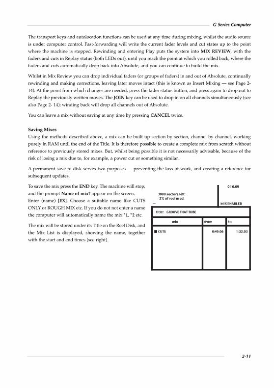
The transport keys and autolocation functions can be used at any time during mixing, whilst the audio source
is under computer control. Fast-forwarding will write the current fader levels and cut states up to the point
where the machine is stopped. Rewinding and entering Play puts the system into MIX REVIEW, with the
faders and cuts in Replay status (both LEDs out), until you reach the point at which you rolled back, where the
faders and cuts automatically drop back into Absolute, and you can continue to build the mix.
Whilst in Mix Review you can drop individual faders (or groups of faders) in and out of Absolute, continually
rewinding and making corrections, leaving later moves intact (this is known as Insert Mixing — see Page 2-
14). At the point from which changes are needed, press the fader status button, and press again to drop out to
Replay the previously written moves. The JOIN key can be used to drop in on all channels simultaneously (see
also Page 2- 14); winding back will drop all channels out of Absolute.
You can leave a mix without saving at any time by pressing CANCEL twice.
Saving Mixes
Using the methods described above, a mix can be built up section by section, channel by channel, working
purely in RAM until the end of the Title. It is therefore possible to create a complete mix from scratch without
reference to previously stored mixes. But, whilst being possible it is not necessarily advisable, because of the
risk of losing a mix due to, for example, a power cut or something similar.
A permanent save to disk serves two purposes — preventing the loss of work, and creating a reference for
subsequent updates.
To save the mix press the END key. The machine will stop,
and the prompt Name of mix? appear on the screen.
Enter (name) [EX]. Choose a suitable name like CUTS
ONLY or ROUGH MIX etc. If you do not not enter a name
the computer will automatically name the mix *1, *2 etc.
The mix will be stored under its Title on the Reel Disk, and
the Mix List is displayed, showing the name, together
with the start and end times (see right).
G Series Computer
2-11
mix
CUTS
0:10.09
MIX ENABLED
3988 sectors left: 2% of reel used.
title: GROOVE THAT TUBE
from to
0:49.06 1:32.03

Update Mixes
Once a Mix List exists, any of the saved mixes can be
specified, and edited on-line as an Update Mix. Update
Mixes are created by placing a copy of the stored mix in
RAM, to become the reference mix to be modified. In this
way, saved mixes are always securely retained, unless
deliberately deleted.
Entering a locate command that refers to a named mix,
such as GOTO MIX (name) [EX] (unless the required mix
is the current item, in which case the name can be
omitted), sets up for an Update Mix. The screen will look
similar to that shown left.
Mix Options in an Update Mix
Before starting an Update Mix, you can select from a complete range of statuses. The five choices can be used
either singly or combined. To select them, either type the first letter or positional number (as shown below). It
is not necessary to press [EX]. Your selection will be indicated on-screen by a square cursor, next to the
abbreviation of that status, in the ‘Mix Options’ box.
Update Absolute (UA: U or 1) — Unavailable in a New Mix. Faders drop into Absolute instead of Trim when
selected. See notes on Trim below.
Play Cuts Only (UA + RC: U & R or 1 & 2 ) — Unavailable in a New Mix. The faders will be in Absolute, with
cuts in either Trim or Replay (dependent on whether Edit Cuts in Play Cuts Only is set to Yes or No on the
Mix Page of the Engineers Setup Menu); fader levels may be changed while the cuts play out unaffected.
Revise Cuts (RC: R or 2) — Unavailable in a New Mix. A two stage process, designed to edit cuts in a more
sophisticated fashion than is possible in Trim. The fader remains in Trim, while the fader status button toggles
the cut between Absolute and Replay — WRITE CUTS and READ CUTS. Fader LEDs will indicate either mode,
(see the Fader Status LED table at the end of this guide).
Autotakeover (AT: A or 3) — Can be used in a New or Update Mix, with Trim or Absolute. Normally, when a
fader is dropped out of write, the level will jump back to the previous written replay level. With AT selected,
when a fader is dropped out, one of the LEDs will flash to show the direction in which to move the fader to
match the replay level. When it matches this level, the fader will automatically drop out of write and back into
Replay. In this way level jumps can be avoided as the operator decides the fade rate between one level and
another.
Preview (PV: P or 4) — Can be used in a New or Update Mix. Preview can be used to rehearse moves, and then
selectively write them to the mix. With PV selected, pressing a fader status button will drop the fader into a
preview mode of the current active write status, as indicated by the flashing LED(s). Any new moves may now
be monitored, while the written mix level remains unaffected. Additionally, the audition and currently written
levels may be compared by toggling the FSM key (displayed on-screen by PREVIEW ON/PREVIEW OFF).
When the desired level is found, the fader status button or JOIN key can be pressed, and any faders in preview
mode will drop into write.
G Series Shortform Guide
2-12
mix
0:47.06Updating CUTS UARCATPVIP MIX ENABLED
READYYou may adjust statusnow. Press EXECUTE to continue
title:
from to
CUTS 0:49.06 1:32.03
GROOVE THAT TUBE

Immediate Pickup (IP: I or 5) — Can be used in a New or Update Mix. When selected, as soon as a fader or
cut is moved/pressed, the channel will drop into write as determined by current selections in the Mix Options
box. With PV and IP selected, moving a fader or switching a cut will put them into Preview mode to audition
new levels, until the status button is pressed to drop them into write. Note that, on consoles fitted with
Ultimation™, IP only has an application in MOTORS OFF.
Level Match
When using the rollback features described above, it may be necessary to physically match a fader level or cut
state, before dropping into write, in order to prevent any undesired level jumps. (On consoles fitted with
Ultimation™ — see below — the fader motors automatically set faders to the correct replay level.)
Pressing the MIX key selects ‘Level Match’ mode, and a LEVEL MATCH legend appears on-screen. The faders
are now disconnected from the mix system and their LEDs illuminate to indicate the match state (it is probably
best, but not essential, to stop the machine at this stage, as you may well be attempting to chase a moving audio
target). Both LEDs on solid indicate that the fader and cut are matched; a flashing green LED means move the
fader up, a flashing red LED indicates that you should move it down; both LEDs flashing indicate the cut
button is inverted. Having set the faders/cuts as required, press the MIX key again to disable Level Match.
Drop the faders that need to be rewritten into Absolute by pressing their fader status buttons.
Using Ultimation™
On consoles fitted with Ultimation, the fader motors can be toggled on/off by typing MO [EX]. When they are
on, MTR will show in the top right of the screen. In Motors On mode, audio passes through the fader itself,
bypassing the VCA, and giving a ‘cleaner’ signal path. In Motors Off the signal passes through the VCA, as in
a normal VCA-equipped console.
If the first mix pass is experimental, (to find rough levels, to be written from the start) after rolling back to the
top, Ultimation faders will reset themselves to their original positions on moving forward again. To avoid this,
turn the fader motors off before rewinding.
In a new mix, in Motors On and Mix Review, to drop a fader into write, simply touch the fader knob; it will
automatically switch from Replay to Absolute.
Dropping out may be achieved in one of two ways, dependent on whether ‘Snap’ mode is currently selected.
Snap mode is toggled by typing SO [EX]); appropriate legends appear top right of the screen.
SNAP ON — The yellow Alt LED lights when the fader is touched; the fader will drop out to Replay as soon
as you remove your finger from the fader.
SNAP OFF — The Alt LED remains off while the fader is held, indicating that the fader will continue writing
until the fader status button is pressed to drop it back into Replay.
Note that the system defaults to SNAP OFF on boot up. If Snap On is currently selected, but an extended move
is necessary, pressing the fader status button will keep the fader in Absolute until the button is pressed again.
G Series Computer
2-13

The Trim Concept
A fader in Trim status always modifies the existing data (ie. the reference mix) by any amount within the range of
the channel VCA. For example, at Cue A the fader is trimmed up by 5dB, down again by 3dB at Cue B, and
switched back to Replay at Cue C; all the previous moves will be retained and played back, but 5dB higher
from Cue A, and just 2dB higher from Cue B to Cue C. If you rewind, and drop the channel back into Trim at
Cue B until Cue C, the previous Trim will be overwritten, and therefore lost — it is not possible to Trim a Trim.
With both VCA and Ultimation systems, when faders are in Trim, audio passes through the channel VCA. The
fader remains free of motor control, allowing delicate moves to be made without concern for accommodating
the ballistics of a moving fader, or chasing a moving target. Additional cuts may be made in Trim, and existing
ones overwritten. For more extensive editing, you should use Revise Cuts. Faders selected to Trim at the head
of a mix are disconnected, allowing them to be renulled to a convenient position.
All the previously discussed tools are available for use with Trim, including Immediate Pickup direct from
Replay.
The Join/Revise Concept
REVISE and JOIN switch faders in Mix Review from Replay back to their write status. These functions only
differ when faders are in Trim (including faders in Revise Cuts).
REVISE — any difference between the fader position and current mix levels will be ignored. When Trim faders
are revised from Replay into write there are no level jumps, as the fader null is recalculated at this point. Thus,
Trim faders may be moved freely to any convenient position whilst in Replay.
JOIN — returns all faders to write as before, but with a level change, the degree of which is determined by any
fader movement made in Mix Review, relative to the last level written before rollback.
Individual channels in Mix Review may be dropped from Replay back into Trim by pressing their faders status
buttons; generally this effects a REVISE dependant on a user option (Selected trim faders will Join in Mix
Review - Yes/No, found in the Mix Page of the Engineers Setup Menu).
Outside rollback (ie. in Mix Running), individual faders switched from Replay to Trim will Revise.
Insert Mixing
New mix moves are written into a separate one-shot buffer memory location, overwriting previous moves,
while the reference mix is stored in RAM. You can therefore choose whether to return to the previous pass level
(the buffer), or the reference mix when switching from a write status back to Replay. The choice, known as
‘Insert Mixing On/Off’, can be selected on the Mix page of the Setup Menu, via the option Insert Mixing
Yes/No.
New Mixes are always Insert Mixes as there is no reference mix to switch to. With the option set to Yes, the
system returns to playing the last pass much like drop-ins on a multitrack. With the option set to No, the system
always returns to the reference mix being updated, losing any subsequent moves made in the previous pass.
G Series Shortform Guide
2-14

Additional Mix Options
Status Retention
Pressing the COPY button at the head of a mix stores all the channels’ statuses, allowing the rapid build-up of
different statuses while progressing through subsequent Update Mixes. Also, in an Update Mix, channels can
be locked in the status they are in at the point of rollback, by pressing the COPY key.
Timed Joins/Revisions
Global drop-in times to return to switch from Replay in Mix Review can be pre-programmed, eg. AT (TIME)
JOIN [EX].
Safe Set
At any point in a mix, selected faders may be made ‘Safe’ by either typing SA at the beginning of a mix, or SAFE
[EX] during the mix, and pressing the required fader status buttons.
The first press (red LED) switches the channel to ‘Safe Manual’ — any changes to faders or cuts affect only the
monitoring, leaving the current mix information intact. The fader is effectively disconnected from the mix
system, so any automation data will not play back.
The second press switches to ‘Safe Replay’ (green LED) — any moves made will neither be heard nor will they
affect the mix data. However, the mix data will play back as usual. This is useful for printing a final mix when
you want to avoid accidental adjustments. If you touch an Ultimation fader that is in Safe Replay, and the fader
motors are on, then that fader will drop into Safe Manual.
Track Copy/Swap Mode
Written mix information can be copied or swapped between channels, only at the start of an Update Mix. At the
start of a mix (MIX READY) press the TRACK key, and toggle between TRACK COPY and TRACK SWAP
using the FSM key. In either case, press the fader status button of the channel to be copied/swapped from, and
then, following the screen prompt, press the status button of the channel to be copied/swapped to. DELETE
will clear the selection to allow you to start again. Once the copy/swap has taken place, the information is held
in RAM; to ave it to the mix, press the END key.
Status Help
A useful feature when learning the system, ‘Status Help’ can be called up at any point during the mixing
process. Enable Help at the head of a mix by pressing the H key; in a mix type HELP [EX]. The fader LEDs will
be switched off. Now, if you select a channel by pressing its fader status button, its current status will be shown
on the screen. Disable Help by repeating the command, and the display will track the selected fader’s status
on-screen as it is switched. Clear that fader’s Help display by re-enabling Status Help, and deselecting the
channel.
G Series Computer
2-15

Software Control Groups
Up to fifteen software control groups can be set up with any fader slaved to any other fader, with any number
of faders in each group; it is not possible for a fader to belong to more than one group. Each slave fader can be
one of five types, which determines its reaction in response to changes on the master; mixed types can exist
within a single group. The slave types are: Slave Fader and Cut, Slave Fader Only, Slave Cut Only, Slave Cut
Inverted, and Slave Status Only.
Software Groups act only on the mix playback. Using the Group Merge command will write grouping data into
the mix, directly onto the slave faders (allowing this data to be edited), and the group is dissolved.
To set up a software group press PRESET and follow the on-screen instructions.
Off-line Mix Facilities
Off-line Mix Trim
The levels of mix moves on selected faders can be adjusted by a specified value, over a defined section. The
command uses the REVISE key. Eg. REVISE MIX (name) +5 [EX] will trim the whole mix up by +5dB. REVISE
MIX (name) +1 FROM (time 1) TO (time 2) [EX] will trim the mix by +1db between the two times. The mix
outside these times will not be affected.
Off-line Mix Join
Stored mixes can be combined in a number of ways, by section and/or selected channels, to form a composite
mix. Enter the required command and follow the on-screen prompts; the options allow cuts to be separated
from the faders. Some examples:
Butt Join: JOIN (mix B) TO (mix A) AT (time)
Insert Join: JOIN (mix B) TO (mix A) FROM (time) TO (time)
Time Shift Join: JOIN (mix A) FROM (time) TO (time) TO (Mix A) FROM (time)
G Series Shortform Guide
2-16

Total Recall (TR)
Total Recall scans and records the positions of all the I/O modules’ front panel controls, faders and
thumbwheels as a single snapshot called a ‘Setup’, stored under the current Title. Recalling a Setup provides a
graphic representation of the selected channel on an external RGB monitor.
To create a Setup, enter NAME SETUP (name) [EX]. Press the fader status buttons on any channels set to I -
‘Independent’, that are to be included, and hit [EX] again. The Setup is now saved and will appear in the LIST
SETUP [EX] list.
To recall a Setup, type PLAY SETUP (Name) [EX]. The RGB display is divided into four sections, with the
channel number and group assignment displayed at the bottom of the screen. Press any channel’s fader status
buttons to display that channel on the RGB monitor.
For rotary controls, the RGB display shows the stored settings in black and highlights any misaligned controls
in white. Resetting a control until the two lines match makes the highlight disappear. Switches are highlighted
white when incorrectly set, press them to match their stored positions; those incorporated within rotary
controls are highlighted to the side of the control graphic (except the large fader Solo Isolate switches,
incorporated in the Group Trim control, which are indicated on the large fader Solo button). The small fader’s
stored position is shown by a black horizontal line.
The on-board monochrome monitor displays the TR instructions page. The console’s fader LEDs will be in
Level Match, indicating the fader positions stored in the Setup. Pressing the T key, causes the red status LEDs
to light on any channels or groups with incorrectly set thumbwheels; once checked, END will return the system
to Level Match.
AutoScan can be used to rapidly scan some or all the channel settings. Press the A key and follow the
instructions on-screen. Once a channel’s settings have been restored, the computer will automatically display
the next unmatched channel
The LARGE/SMALL key enables specific areas of the module to be displayed in an enlarged form, and will
automatically track to that section of the module when a control is operated.
Useful Tip: TR Setups can use a lot of disk space. Instead of taking a fresh Setup each time, you can simply
update an existing Setup by using REVISE SETUP (name) [EX]. The computer will then store only the
differences between the named Setup and the current console settings.
G Series Computer
2-17

LED Reference Table for Fader Statuses
New MixNo LED Manual/Replay
Red LED, solid Absolute
Red LED, slow flashing Preview Absolute
Update MixNo LED Replay/Safe
Red LED, solid Absolute
Green LED, solid Trim
Red LED solid + green LED flashing Play Cuts Only
Green LED + red LED, solid Revise Cuts Write
Green LED solid + red LED flashing Revise Cuts Read
Red LED, slow flashing Preview Absolute
Green LED, slow flashing Preview Trim
Red LED slow flashing
+ green LED flashing Preview Play Cuts Only
Green LED slow flashing
+ red LED, solid Preview Revise Cuts
Red LED, fast flashing Direction indicators
Green LED, fast flashing for Autotakeover
Ultimation OnlyYellow LED Snap On mode
All LEDs lit Fader stall
G Series Shortform Guide
2-18

G Series Computer
2-19
DATA CARTRIDGE AND DISK DRIVESBEGIN EX .................................. Re-loads program FORMAT EX .............................. Formats new Data Cartridge (DC) (5 mins)
or 3.5"Reel Disk (1 min).A must!LABEL EX .................................. Sets choice of REEL size if using DC or
‘labels’ Reel Disk as required. Essential! ALTER EX .................................. Stores current List page info for further
transfer to REELS and Reel DisksLOAD EX ................................... Loads the default floppyFLOPPY EX ................................ Makes 8" disk current Reel DiskMINI EX ..................................... Makes 3.5" disk current Reel DiskDI EX .......................................... Displays remaining current Reel space
SIGN_ .................EX............. Changes Program start sign on message HERE EX .................................... Makes a NOW cue point for use in locate
command lines. ? HERE EX ................................. Displays current timecode value SET_CL EX ................................. Sets Time and Date clock TI EX ........................................... Displays clock DELETE (whatever) EX ........... Whatever must be specified. The item
name of the TITLE, MIX etc may be abbreviated as usual
SETUP EX .................................. Accesses Setup Menu (customising pages)
Time as referred to here by a) Last time specified TIME can be: .............................. b) Timecodes hh:mm:ss.ff or hhmmssff
c) Feet' Frames d) TITLE, MIX, CUE, HERE, DROP-IN
(t) indicates a specific value of time i.e. . 6(6 frames), 3. (3 secs) etc.
GENERAL
Flashing SMPTE, EBU, DF TC System is set (incorrectly) for this type of or FILM ............................ timecode. Solid display when set correctly
Flashing smpte, ebu, df tc System needs to be reset to this type of or film ............................... timecode in Setup Menu
SMPTE?, EBU?, DF TC? or FILM? Wrong Speed/Tach rate. Wrong Master machine selected in Setup Menu
SMPTE*, EBU*, DF TC* or FILM* No Tach ???? .............................................. Synchroniser gone awayLARGE/SMALL key ................ Toggles large display of current timecode
or Sync page with current page display SMPTE, EBU or STRIPE EX .... To generate timecode. Set type in Setup MenuOFF_TIME EX ........................... Sets up REEL/Reel Disk offset OFF_: .......................................... Cancels REEL/Reel Disk offset SP_30 (or 15) EX ........................ Changes Speed on List page. (MUST be
correct for current Master machine)
TIMECODE
TITLE LIST EX SETUP ........... Displays Tempo Map nnn.n EX .................................... With cursor in Tempo column, defines
tempo in the range 40-400 BPM0 EX ............................................ Enables entry of Tempo by tapping any
key (not EX). Hit EX to enter value3 EX 4 EX, 7 EX 8 EX etc. .......... Enters time signatureTRACK key ............................... Displays Bar value of ‘To’ timesGOTO nn# EX .......................... Locates to Bar nnBB EX .......................................... Toggles display of Bar/Beats and TimecodeDELETE key .............................. Hit twice to delete entire Tempo Map
BAR/BEATS
TAPE CONTROL
NB. The REEL key replaces the SEQUENCE key used on E Series keyboards
NAME REEL Name EX ........... Creates and names REEL on the current DC.NAME REEL (A) or (B) Name EX . Creates a REEL on a specific driveREEL Name EX ......................... Makes that REEL current REEL (A) or (B) Name EX ....... Makes that REEL and that DC current REEL (A) or (B) Name ............. Lists TITLES on REEL ‘Name’ and makes
TITLE EX ......................... first TITLE on list currentREEL X TITLE A EX ................ Makes Title A on REEL X current DELETE REEL Name EX ........ Deletes the named REEL. Fairly lethal! REEL X NAME Y EX ............... Renames REEL X
NB.When defining DC with (A) or (B) the brackets must be entered in command line.
(LIST) REEL EX ........................ Displays REEL List (LIST) REEL (A) or (B) EX ...... Lists REELS on DC in A or B drive LIST EX ...................................... Displays Information page of
current REEL or Reel Disk (LIST) TITLE, TRACK
or MIX etc EX ................. Gives a list of the specified itemTITLE LIST EX ......................... Accesses Notes Pages for reading or writing NAME TRACK (n) EX ............ Enables TRACK List entriesLeft/Right cursor keys ............ Scan through CUES, MIX, SYNC PRESET,
TR SETUP, TRACK, NOTES pagesUp/Down cursor keys ............ Give alternative information associated
with TITLE, MIX and TR SETUP lists
NAME TITLE (FROM TIME) (TO TIME) EX ................. Enters new TITLE
NAME TITLE (Name) Enters new TITLE starting at current time TO TIME EX .................... and ending at TIME
TITLE (Name) FROM TIME EX Changes TITLE start time (and re-sorts list)TITLE (Name) TO TIME EX .. Changes TITLE end time TITLE END TIME EX .............. As above TITLE END EX ......................... Clears TITLE end timeTITLE (Name) NAME Renames title. Same syntax used for
(New Name) EX .............. cues, mixes etc.
LISTS
GOTO (TIME) EX or If TIME is not entered, the last specifiedPLAY (TIME) (TO TIME) EX .. target is assumed
HERE EX .................................... Sets a NOW target for GOTO EX, PLAY EX etc. or Mix data changes
PLAY FROM TIME (TOTIME) EX ......................... Plays for ever if TO time is not specified
CYCLE ((FROM TIME) Cycles from last locate target if FROM TO TIME) EX .................. TIME is not specified
PLAY CYCLE EX ...................... Reinstates an interrupted cycleCYCLE EX ................................. Cycles to NOW from the last specified locate target
+/- (t) EX .................................... Overrides Setup Menu default time valueof +/- keys
+/- EX ......................................... Locates and plays+/- GOTO EX ........................... Locates and parks+/- CYCLE EX .......................... Locates and cyclesQ EX ......................................... Toggles the option to locate the machine
to target without preroll
REELS
G Series Command Reference

G Series Shortform Guide
2-20
CUE EX ...................................... Defines CUE point at current time,computer numbered
CUE Name AT TIME EX ......... Defines a named CUE point at TIMECUE (Name) TO TIME EX ...... Changes time of CUE point (and re-sorts list) CUE (Name) +/- (t) EX ........... Nudges cue time by one frame if it is not specifiedREVISE CUE FROM CUE X Re-sorts Cue List so that CUE X is now at
TO CUE Y TO TIME EX .... TIME and subsequent Cues on the list up to Y are time shifted accordingly
DELETE ALL CUE, MIXSETUP etc EX ................. Deletes all items on the specific list
DELETE CUE 1 CUE 2 CUE 3 etc EX ................... For selective multiple deletions
DELETE TITLE LIST EX ........ Deletes all Notes in current TITLE
LISTS (cont)
DROP-INSNB. On SL 4000/6000/8000 Series systems, Drop-ins will be REHEARSEDon monitor if desk TRACK READY is set but RECORD ENABLE is NOTset. To Drop-in for real, set RECORD ENABLE.
DROP-IN EX ............................. Plays and sets Drop-in for indefinite recording DROP-IN EX..........EX .......... Sets Drop-in and out times on the flyDROP-IN FROM TIME
TO TIME EX .................... Sets Drop-in and out times DROP-IN END EX .................. Clears Drop-out time DROP-IN AT TIME EX ........... Resets Drop-in time but not Drop-outtimeDROP-IN TO TIME EX .......... As above DROP-IN (END) +/-(t) EX .... Changes Drop-in or out times by one
frame or specified time (t)LIST DROP-IN EX .................. Displays Drop-in and out times GOTO DROP-IN EX ............... Guess what !PLAY DROP-IN FROM
TIME EX ........................... Plays Drop-in from TIME CYCLE DROP-IN (FROM
TIME) EX ......................... For multiple Drop-in rehearsalAT TIME DROP-IN EX ........... Locates and drops in at TIME for
indefinite recording AT DROP-IN EX ...................... As PLAY DROP-IN but clears Drop-out time +/-(t) DROP-IN EX ................. Locates and drops in at time set by +/- keysPLAY FROM DROP-IN EX .... Locates but does not perform the Drop-in
NAME SETUP (Name) EX (EX) Stores complete scan of desk REVISE SETUP (Name) EX (EX) Changes existing Setup to current settings PLAY SETUP (Name) EX ........ Runs Total Recall and displays Setup LIST SETUP EX ....................... Lists Total Recall Setups ! LARGE/SMALL Key .............. Zooms in on section of display
TOTAL RECALL
PRINTERPRINT ........................................ Prints screendumps if this feature
enabled in Setup Menu Otherwise:
PRINT TITLE EX ..................... Prints every List in the current TITLE PRINT MIX, CUE,
SETUP etc EX .................. Prints that list from current TITLE PRINT TITLE LIST EX ........... Prints Notes Pages from current TITLE
COPYING INFORMATIONWARNING
G Series and Ultimation mixes are not backwards compatible with E Seriessoftware.
Stored information can be copied from the current area to another area orcopied from another area to the current area or between two other areas asrequired e.g:
NB. Omit (A) or (B) from command lines if copying within the same DC
COPY ALL EX ........................... Copies Program Disk or any floppy to floppy
COPY REEL EX ........................ Specifically copies Reel Disk to anotherfloppy
COPY CUSTOM EX ................. Copies custom Setup parameters to newProgram Disk
BACKUP EX .............................. Makes copy of DC in drive A to DCin drive B
COPY FLOPPY TO REEL ....... Copies 8" Reel Disk to a REEL(A/B) Name EX
COPY REEL (A) Name TO Copies REEL to 8" Reel Disk if there’s FLOPPY EX ...................... room!
COPY REEL (A) Name TOREEL (B) Name EX ....... Copies REEL and renames it
COPY TITLE Name TOREEL (A/B) Name EX ... Copies TITLE to another REEL
COPY TITLE Name TO Copies TITLE on current REELMINI EX ........................... to 3.5" Reel Disk
COPY TITLE 1 FROM REEL Copies TITLE 1 from REEL X to (A/B) X EX ...................... current REEL
COPY MIX 1 FROMTITLE X EX ..................... Copies Mix 1 to current TITLE
COPY REEL X TITLE 1 Copies Mix from another REEL to MIX 3 EX ......................... current TITLE
Total Recall SETUPS are copied in the same way as Mixes.Substitute SETUP for MIX.
COPY CUE FROM (REEL Replaces CUE list in current TITLE Name) TITLE 1 EX ......... with TITLE 1 CUE list
COPY CUE TO TITLE 1 EX ... Current CUE list overwrites CUElist in TITLE 1
BEWARECopying a Cue list to a Title will overwrite any existing Cue list for that Title. If
the destination Title specified does not exist, you have the option to create it.
Track lists are copied in the same way as Cue lists - substitute TRACK forCUE. (This facility replaces NAME TRACK FROM TITLE). Substitute SYNCPRESET for CUE to copy Sync Presets. Substitute LIST for CUE to copyNotes Pages and Bar/Beat Tempo Map.

G Series Computer
2-21
Although SSL offer both VCA-based G Series and G Series with Ultimationmoving faders, almost all of the mix commands are common to both systems.Any differences mostly apply to default fader status and status indication.Please note that this card does not cover the G Series moving fader systemfitted to SL5000M consoles.
All G Series mix systems operate in two basic modes - New Mixes where anoriginal mix is created from scratch and Update Mixes where a mix,previously created and stored on disk, is edited.
NEW MIXESSETUP MIX EX ........................ Enables mix system, and starts mix here MIX ON/OFF key ..................... Followed by any locate command,
enables mix from locate target
Mix Options
1. UA UPDATE ABSOLUTE*2. RC REVISE CUTS3. AT AUTOTAKEOVER4. PV PREVIEW5. IP IMMEDIATE PICKUP
UA + RC = PLAY CUTS ONLY
The above may be selected or de-selected at the start of, or during a mix, bytyping either the associated number (1, 2, etc.) or the first letter (U, A,etc.) ofthe required control name. Selected controls are indicated by a blot on thescreen display. Any selected controls may be cleared down (to Setup Menustandard) at any time by typing 0 (zero). Note that controls 1 and 2 are notavailable in a New Mix and are therefore not displayed.
MIXING
FADER STATUSChanges to fader status at the head of, or during a mix may be madeindividually using fader status buttons. Across the board changes at the headof a mix are made using the Fader Status Master key (FSM).
ABSOLUTE Red LED PREVIEW ABSOLUTE Flashing red LEDMANUAL (See SAFE MODE) No LEDsREPLAY No LEDsTRIM Green LEDPREVIEW TRIM Flashing Green LEDTRIM (Fader) READ CUTS Green + flashing Red LED TRIM (Fader) WRITE CUTS Green + Red LEDABS (Fader) READ CUTS (UA + RC) Red + flashing Green LED
NB. On Ultimation systems only, the yellow alt LED indicates SNAP ON mode; all LEDs flashing indicate a fader stall.
Fader Status Cycles in a New Mix
CONTROL READY MIX RUNNING MIX REVIEW
None ABS ABS REPLAYMANUAL ABS
PV ABS ABS REPLAYP/VIEW ABS P/VIEW ABS* P/VIEW ABS*
ABS ABS ABS
PV+AT ABS ABS REPLAYP/VIEW ABS P/VIEW ABS* P/VIEW ABS*
ABS ABS ABSAUTOTAKEOVER
Autotakeover allows faders to be switched to REPLAY automatically whenthe fader crosses the previous pass level of the mix being edited.
* Toggle between PREVIEW ON (current fader levels) and PREVIEW OFF (written levels) using the FADER STATUS MASTER (FSM) key.
On non-moving fader systems, with IP selected, faders and cuts switch fromREPLAY to ABS, or PREVIEW ABS, on touch in MIX REVIEW.
Ultimation Systems Only
The yellow alt LED indicates SNAP ON mode when lit. In SNAP ON, touchthe fader to write, take finger off to return to Replay; individual faders maybe switched to SNAP OFF by pressing their fader status buttons. In SNAPOFF, touch fader to write, use fader status button to return to Replay. AllLEDs flashing indicate fader stall.
SO EX .......................................... Toggles SNAP ON/OFFMO EX ........................................ Toggles MOTORS ON/OFF. (period key) ............................. Displays current state of
MOTORS ON/OFF
UPDATE MIXESSETUP MIX HERE EX ............ Sets up for Update of current mix here SETUP MIX Name EX ............ Sets up for Update of mix ‘Name’GOTO MIX (Name) EX .......... Locates and parks at start of Update mixPLAY MIX (Name) EX ............. Locates and starts Update mix PLAY FROM MIX (Name) EX Locates to start of selected mix,
plays past end of selected mixGOTO/PLAY/CYCLE MIX
(Name)FROM TIME(TO TIME) EX ................. Creates an mix with updated section but
at least as long as the mix being updated
Fader Status Cycles in an Update Mix
Default starting status in an Update Mix can be set in the Mix Options Pageof the Setup Menu. The following table assumes Replay has been selected.
CONTROL READY MIX RUNNING MIX REVIEW
None REPLAY REPLAY REPLAYTRIM TRIM TRIM ABS REPLAY REPLAY

G Series Shortform Guide
2-22
MIX COMMANDS (all systems)END ............................................ Stops mix and asks for name CANCEL (twice) ....................... Cancels current mixLARGE/SMALL key ................ Toggles bargraphs with current page
display if bargraphs are enabledFSM key ..................................... Toggles ‘Status Locked’ mode, except
when faders are in a Preview status or theFSM key is assigned to the Master Fader
Other Status Controls
UA, RC or UA + RC will allow faders to be switched to ABS, READ/WRITECUTS or ABS FADER READ CUTS from any previous status, at any pointbefore or during the mix, by using the status buttons or the Fader StatusMaster key at the head of the mix only.
IP sets faders and cuts to the appropriate status e.g. ABS, WRITE CUTS etc.immediately on moving the fader in MIX REVIEW. With Ultimation,channels only switch when the state of a cut is changed.
PV allows faders to be selected to a PREVIEW of the update status selected.PREVIEW ON/OFF can be toggled during the mix, with the FSM key and canalso be used in MIX REVIEW to selectively JOIN faders to the mix - see JOINand REVISE.
AT allows faders to be switched to REPLAY automatically when the fadercrosses the reference level of the mix being updated. Autotakeover is notavailable with RC (REVISE CUTS mode) as this mode is specifically designedto toggle READ/WRITE CUTS status.
MIXING (cont)
MIX ............................................. Selects LEVEL MATCH. (Choose faderswith buttons or all with FSM if LocalFader Level Match = YES in Setup Menu)
JOIN or REVISE ...................... Enables MIX RUNNING from MIXREVIEW on all channels. With PV selected, only channels in Preview status
AT TIME JOIN (REVISE) EX Specifies end of rollback AT TIME EX .............................. Switches faders to preview levels at TIME-(t) JOIN/REVISE EX................. Rolls back by value of - key plus run-up
time and JOINS/REVISES at target timedetermined by the - key
HERE EX .................................... Sets/Updates current JOIN/REVISEpoint
enabling AT EX or AT JOIN EXcommands. Also Sets/Updatescurrent locate target
COPY (Head of Mix only) ...... Stores current fader status for startingfurther Update mixes until Mix System isdisabled with MIX ON/OFF key
FROM EX .................................. Logs current fader statuses TO EX ......................................... Restores statuses logged with FROM EXBA EX ......................................... Toggles bargraph display on or off* key ............................................ Switches through name of mix, sectors
used, FSM assignment, Master Faderstatus, Insert Mixing on/off and Mix Options Box selection
PRESET ...................................... Accesses/clears Software GroupSetup menu
? MIX or ? END MIX EX ........ Displays mix start or end time with frames? END MIX- MIX EX ............... Displays length of mix
MIX COMMANDS (continued)MIX ............................................. Selects LEVEL MATCH. (Choose faders
with buttons or all with FSM if LocalFader Level Match = YES in Setup Menu)
JOIN or REVISE ...................... Enables MIX RUNNING from MIXREVIEW on all channels. With PV selected, only channels in Preview status
AT TIME JOIN (REVISE) EX Specifies end of rollback AT TIME EX .............................. Switches faders to preview levels at TIME-(t) JOIN/REVISE EX................. Rolls back by value of - key plus run-up
time and JOINS/REVISES at target timedetermined by the - key
HERE EX .................................... Sets/Updates current JOIN/REVISEpoint
enabling AT EX or AT JOIN EXcommands. Also Sets/Updatescurrent locate target
COPY (Head of Mix only) ...... Stores current fader status for startingfurther Update mixes until Mix System isdisabled with MIX ON/OFF key
FROM EX .................................. Logs current fader statuses TO EX ......................................... Restores statuses logged with FROM EXBA EX ......................................... Toggles bargraph display on or off* key ............................................ Switches through name of mix, sectors
used, FSM assignment, Master Faderstatus, Insert Mixing on/off and Mix Options Box selection
PRESET ...................................... Accesses/clears Software GroupSetup menu
? MIX or ? END MIX EX ........ Displays mix start or end time withframes? END MIX- MIX EX ............... Displays length of mix MF EX ......................................... Makes FSM the Master Fader status
selectorHELP EX .................................... Enables STATUS HELPSAFE EX ..................................... Enables SAFE SETTRACK (in mix READY only) Enables TRACK COPY/SWAP mode.
Use FSM to choose COPY or SWAPSL (in mix READY only)............. Toggles ‘Status Locked’ mode. Do not hit
EX after SL unless you want to start the mix!
SOFTWARE CONTROL GROUPSUp to 15 separate software groups, with any number of faders in each group,may be set up at any time – out of a mix or during mixing i.e. Mix Ready,Running or Review. Select the Group Setup Menu with the PRESET key.Up/Down cursor keys select slave type, Left/Right keys select groupnumber. Select faders with fader status buttons - Master first (red LED)followed by slaves (green LED). RUB key clears current group. To exit menupress PRESET again. Group information is ‘monitor only’ until merged withmix data by using the COPY key when group menu is on the screen and thegroup to be merged is current. Once merged, groups are dissolved.

G Series Computer
2-23
MIXING (cont)
OFF-LINE CUTSSETUP PRESET MIX Enables off-line Cut creation without
(AT TIME) EX .................. running tape machine
To display and edit cut data for individual faders enter LIST Fnn EX for ChannelFader nn. Use Vn for Groups, Sn for Patchable VCAs and M1 for the Master fader.Move cursor to time column to enter EDIT MODE. Then:
GOTO, PLAY, CYCLE keys ...... Locate to and play eventsREVISE key ................................ Toggles cut/uncut stateJOIN key ..................................... Inserts new cut event on the line aboveDELETE key ............................... Deletes current cut event (for ever!)COPY key ................................... Enables the same event to be modified on
multiple channelsEND key ...................................... With cursor in the Cue column, saves
edited cuts as a Mix to disk
OFF-LINE CREATION AND JOINING OF MIXESREVISE MIX Name ±n.n Initiates a trim of ±n.n dB for the specified
(FROM TIME TO TIME) EX time.REVISE MIX Name TO G EX Copies G Series or Ultimation mix for use
with earlier G 2.12 software. E Series andG2.12 mixes are automatically convertedfor use with Ultimation and current G Series
REVISE MIX Name FROMTIME TO TIME EX .............. Creates a shortened mix from mix ‘Name’
REVISE MIX Name FROM Creates a new mix from (a section of) MixTIME TO TIME ‘Name’ and time shifts it to start at the TO TIME EX ......................... second TO time
JOIN (MIX) B TO (MIX) A Off-line Butt join resulting in Mix AAT TIME EX ......................... followed by Mix B
JOIN (MIX) B TO (MIX) A Off-line Insert join resulting in Mix AFROM TIME TO TIME EX ..... followed by Mix B followed by Mix AJOIN (MIX) A FROM
TIME TO TIME TO Time shifts portion of Mix A and(MIX) A FROM TIME EX .. inserts it back into Mix A
JOIN (MIX) A FROMTIME TO (MIX) B FROMTIME TO TIME EX .............. As above with different mixes
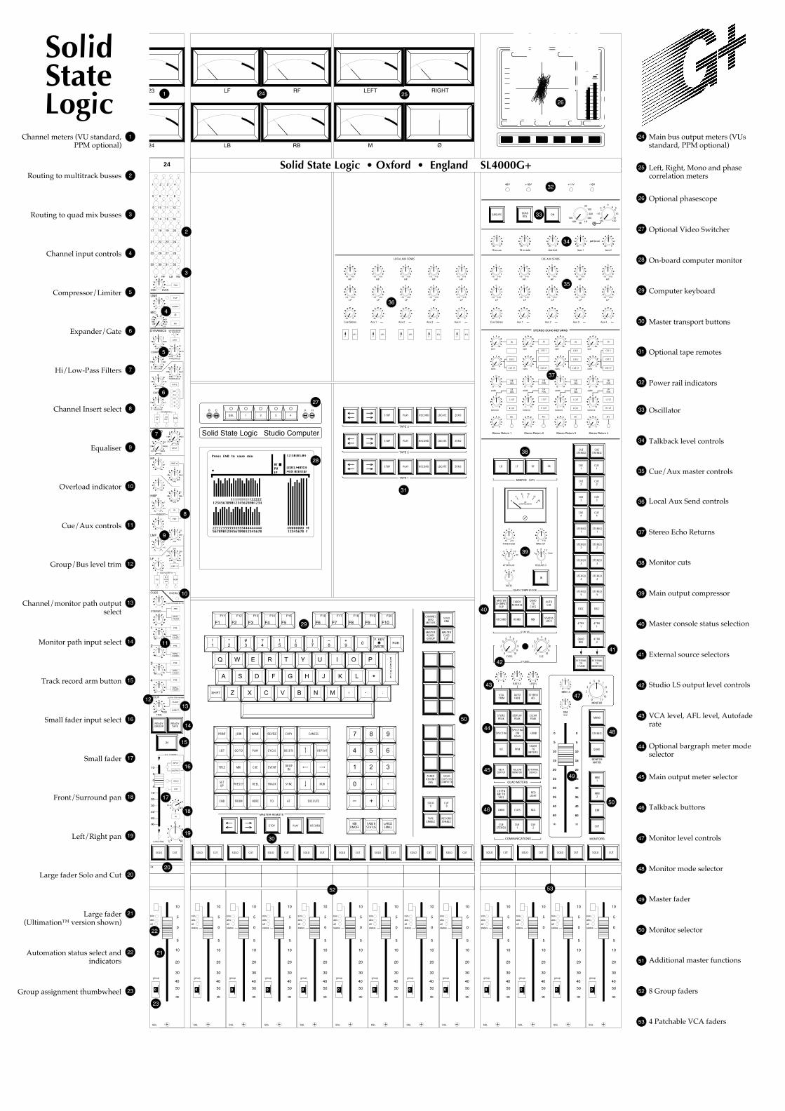
RBLB
LF RF
SSL 1 2 3 4
B C V H
C
MS
0¥
L R
C
balance
L CUT
R CUT
AFL
F/BPAN
L/RPAN
width
C
MS
0¥
L R
C
balance
L CUT
R CUT
AFL
F/BPAN
L/RPAN
width
C
MS
0¥
L R
C
balance
L CUT
R CUT
AFL
F/BPAN
L/RPAN
width
C
MS
10
5
0
5
10
20
30
50
¥
group
trim
abs
status
40
0
alt
SSL
10
5
0
5
10
20
30
50
¥
group
trim
abs
status
40
0
alt
SSL
10
5
0
5
10
20
30
50
¥
group
trim
abs
status
40
0
alt
SSL
10
5
0
5
10
20
30
50
¥
group
trim
abs
status
40
0
alt
SSL
543
2
10
67
8
910
543
2
10
67
8
910
MINI LS
54321
0
6789
10
CUE2
CUE1
CUESTEREO
M.D.CUESOMNI
REDLIGHT
LISTENMIC TOTAPE
SOLO CUT SOLO CUT SOLO CUT SOLO CUT
0
C
-20 +20
FLIP
SUBGP
¯
48v
LINE
MIC
PAN
ODD EVEN
+4 +70
LF RF LB RB
29 30 31 32
25 26 27 28
21 22 23 24
17 18 19 20
13 14 15 16
9 10 11 12
5 6 7 8
1 2 3 4
°
°
°
60
GROUP
FLOAT
DIRECT
INPUT
OUTPUT
SOLO
CUT
from CHANNEL
to ROUTING
C
L R
0dB-30
10
5
0
5
10
20
30
°
40
PRE
SMALLFADER
3
PRE
SMALLFADER
4
PRE
SMALLFADER
2
°
PRE
SMALLFADER
1°
PRE
SMALLFADER
STEREO
L R
READYTAPE
READYGROUP
24
SOLO CUT
pull for Solo Isolate
F
S
IN
TRIM
C
GATE
CHIN
CHOUT
MON
SPLIT
HMF x3
INSERT
IN
PRE
¸LMF 3
CHFLTDYNS/C
MON
EQUALISER to
DYNAMICS to
EXPAND
FILTERS
HF
HMF
LMF
LF
C
CUES OVERLOAD
push for busses 25 - 32
LINK
DYNAMICS
COMPRESS
101622
2834 40
5258
64
1 °
2
3 8
20
5
RATIO
RELEASE
THRESHOLD
pull RELEASEfor fast attack
+10 -20
+5
0 -10
-15
-5
.1 4
.15
.2 1
2
.4
F
THRESHOLD-30 +10
-25
-20 +4
+5
-12
0 40
5
10 30
35
20
RANGE
RELEASE.1 4
.15
.2 1
2
.4
F
20
14
10
6
3
OUT 350
20
70 200
300
120OUT 3
12
8 4
3.5
5
Hz
kHz
Ð +
Ð +
Ð +
Ð +
0
0
0
0
1.5 16
2
5 10
14
8
kHz
.6 7
.8
1.5 4.5
6
3
kHz
.2 2.5
.3
.8 1.5
2
1
kHz
30 450
50
100 300
200
Hz
3
2 1
.5
1.5
3
2 1
.5
1.5
10
5
0
5
10
20
30
50
¥
group
trim
abs
status
40
0
alt
24
SSL
Z X C V B N M , . :
A S D F G H J K L *
Q W E R T Y U I O P
!1
"2
#3
?4
EXECUTE
F1
F11
F2
F12
F3
F13
F4
F14
F5
F15
F6
F16
F7
F17
F8
F18
F9
F19
F10
F20
MASTERREADYGROUP
MASTERCUESCUT
TAPEENABLE
RECORDENABLE
SOLO CUT SOLO CUT SOLO CUT SOLO CUT SOLO CUT SOLO CUT SOLO CUT SOLO CUT
STOP PLAY RECORD
MASTER REMOTE
!5
(6
)7
Ð8
+9 0
F. KEY
WRITERUB
SHIFT
PRINT JOIN NAME REVISE COPY CANCEL
LIST GO TO PLAY CYCLE DELETE REPEAT
TITLE MIX CUE EVENT DROPIN
SETUP PRESET REEL TRACK SYNC RUB
END FROM HERE TO AT EXECUTE
MIXON/OFF
FADERSTATUS
LARGESMALL
7 8 9
4 5 6
1 2 3
0
Ð + CUT0
CHANNELINTO
METERS
SOLOLINK
,
¬¬
®®
FADERREV INH
RHS
SOLOCUTS TO
COMPUTER
10
5
0
5
10
20
30
50
¥
group
trim
abs
status
40
0
alt
SSL
10
5
0
5
10
20
30
50
¥
group
trim
abs
status
40
0
alt
SSL
10
5
0
5
10
20
30
50
¥
group
trim
abs
status
40
0
alt
SSL
10
5
0
5
10
20
30
50
¥
group
trim
abs
status
40
0
alt
SSL
10
5
0
5
10
20
30
50
¥
group
trim
abs
status
40
0
alt
SSL
10
5
0
5
10
20
30
50
¥
group
trim
abs
status
40
0
alt
SSL
10
5
0
5
10
20
30
50
¥
group
trim
abs
status
40
0
alt
SSL
10
5
0
5
10
20
30
50
¥
group
trim
abs
status
40
0
alt
SSL
MINI1
MINI2
DIM
CUT
FOLLOWMONITOR
DIMlevel
MONO
STEREO
MONITORMATRIX
MONITORSCOMMUNICATIONS
QUAD
STOREPEAK
DISPLAYPEAK
CLEARPEAK
+20dBSPECTRA
ONSOLO
SPECTRA
PPMVU
60
40
35
30
25
20
15
10
5
0
¥
MONITOR
5
01
2
3
46
7
8
9
1011
FADERTO
METERS
EXTERNALSOURCE
60
40
35
30
25
20
15
10
5
0
¥
DESKOUTPUT
VCATRIM
AUTOFADE
LEVEL
STEREOAFL
RATE-S
QUAD METERS
MASTERCH INPUT
FLIP
FADERREVERSE
RECORD REMIX MIX STATUSLOCK
CUES
QUADTO
CUES
AUTOCUE
SLS
STUDIO
STATUS
EXTERNALTO
STUDIO
EXTERNALTO
MONITORS
STEREO1
STEREO2
STEREO3
STEREO4
STEREO5
DISC
4 TRK1
QUADBUS
STEREO1
STEREO2
STEREO3
STEREO4
STEREO5
4 TRK1
4 TRK2
DISC
7.5
+15
0
-15 +15
THRESHOLD
ATTACK-mS
RATIO
MAKE-UP
RELEASE-S
2 4 10
.1
.3 .6 1.2
Auto
0
IN
QUAD COMPRESSOR
MONITOR CUTS
.1
.31 3
10
30
LF RBLB RF
0
48 12
16
20
dBCOMPRESSION
Stereo Return 4Stereo Return 3Stereo Return 2Stereo Return 1
CUE-AUX SENDS
0
-15 +15
0
-15 +15
0
-15 +15
0
-15 +15
0
-15 +15LF LF LF LF LF
0
-15 +15
0
-15 +15
0
-15 +15
0
-15 +15
0
-15 +15HF HF HF HF HF
0¥ 0¥ 0¥ 0¥ 0¥Cue Stereo Aux 1 Aux 2 Aux 3 Aux 4
0¥
0¥
L R
¥off
C
spin
cans
balance
IN
CUE 2
CUE ST
L CUT
R CUT
AFL
0¥
¥offspin
cans
IN
CUE 2
CUE ST
CUE 1
0¥
¥offspin
cans
IN
CUE 2
CUE ST
CUE 1
STEREO ECHO RETURNS
0¥
¥offspin
cans
IN
CUE 1
CUE ST
F/BPAN
L/RPAN
width
48V +18V +11V -18V
05
10
+20
-10
-550
100
220
440
1K10K3K
15Kcal.
0¥ 0¥ 0¥ 0¥ 0¥TB to cans TB to studio slate level listen 1 listen 2
pull to cut
ONQUADBUS
GROUPS
24
IIIINNNNFFFFOOOO 22220000ddddBBBBOOOOUUUUTTTT UUUUTTTTIIIILLLL SSSSPPPPEEEECCCCTTTT PPPPPPPPMMMM
++++11112222
––––11118888
––––22224444
––––33330000
––––33336666
––––44442222
++++6666
TTTTEEEESSSSTTTT
––––6666
––––11112222
++++9999
––––1111
++++1111
0000
MMMMOOOONNNNOOOO
++++SSSS ----SSSS
RRRRLLLL
AAAANNNNAAAALLLLOOOOGGGG OOOOVVVVRRRR 0000
M
LEFT RIGHT
Solid State Logic • Oxford • England SL4000G+
CUESTEREO
CUE1
CUE2
CUE3
CUE4
CUESTEREO
CUE1
CUE2
CUE3
CUE4
Solid State Logic Studio Computer
123456789012345678901234111111111122222
222223333333333444444444 VVVVVVVV M12345678 F567890123456789012345678
Press END to save mix 12:30:03.04
ATPVIP
LEVELMIX REVIEW
MATCH
STOP PLAY RECORD¬¬
®® LOCATE ZERO
TAPE 3
STOP PLAY RECORD¬¬
®® LOCATE ZERO
TAPE 2
STOP PLAY RECORD¬¬
®® LOCATE ZERO
TAPE 1
26
SOLO0
¯24
23
LOCAL AUX SENDS
0
-15 +15
0
-15 +15
0
-15 +15
0
-15 +15
0
-15 +15LF LF LF LF LF
0
-15 +15
0
-15 +15
0
-15 +15
0
-15 +15
0
-15 +15HF HF HF HF HF
0¥ 0¥ 0¥ 0¥ 0¥Cue Stereo Aux 1 Aux 2 Aux 3 Aux 4
AFL AFLAFL AFL AFL
2
3
4
5
1
Expander/Gate
Routing to multitrack busses
Routing to quad mix busses
Channel input controls
Compressor/Limiter
Channel meters (VU standard, PPM optional)
Hi/Low-Pass Filters
Channel Insert select
Equaliser
Overload indicator
Cue/Aux controls
Group/Bus level trim
Channel/monitor path output select
Monitor path input select
Track record arm button
Small fader input select
Small fader
Front/Surround pan
Left/Right pan
Large fader Solo and Cut
Large fader(Ultimationª version shown)
Automation status select and indicators
6
2
3
4
5
1
7
8
9
10
11
12
13
14
15
16
17
18
19
20
21
22
23Group assignment thumbwheel
6
7
8
9
10
11
1213
14
15
17
16
18
19
20
21
22
23
25
27
28
29
30
32
33
34
35
37
38
39
40
41
42
43
44
47
45
46
49
48
50
29 Computer keyboard
Left, Right, Mono and phase correlation meters
24
25
26
27
28
Optional phasescope
Optional Video Switcher
On-board computer monitor
Main bus output meters (VUs standard, PPM optional)
30 Master transport buttons
31
32
Optional tape remotes
Power rail indicators
33
34
Oscillator
Talkback level controls
35
36
Cue/Aux master controls
Stereo Echo Returns37
38 Monitor cuts
Main output compressor39
40 Master console status selection
External source selectors41
42 Studio LS output level controls
VCA level, AFL level, Autofade rate
43
44 Optional bargraph meter mode selector
Main output meter selector45
46 Talkback buttons
Monitor level controls47
Monitor mode selector48
49 Master fader
Monitor selector50
Additional master functions51
8 Group faders52
4 Patchable VCA faders
50
52 53
24
StateLogic
Solid
31
36
53
Local Aux Send controls

REC
+
-
+
-
CH OUT
GROUP MONITORINPUTS
EQ F
EQ F
EQ F
DYN
S/C
DYN
S/C
DYN
S/C
VCA PRE Insert
A
B
DYN
S/C
D
FLIP ¯
SPLIT CH IN
IN
PRE
F
IN
CH
F
FLTDYNS/C
AFL
CUT
COMPUTER RETURN
AFL BUS
GROUP OUTPUTS(MTR SENDS)
VCA POST Insert
A
MICTRIM
+4 Ñ +70dB
LINETRIM
-20 Ñ +20dB
+48VPHANTOM
POWER
MIC INPUTS
LINE INPUTS(MTR RETURN)
TAPE MONITORINPUTS
READYTAPE
SUB GP
READYGROUP
MASTERREADYGROUP
STEREO LINK
LINK
CH IN
MON MON
CH OUT
INPUTOUTPUT
OUTPUT
CUT
OVERLOAD+20dBu
CHANNEL INSERT
CUT
VC
A G
RO
UP
DC
LARGE FADER
COMPUTER SEND
COMPUTER RETURN
CHANNEL VCA
VCA DC LEVEL(to METER SEL)
VCA FADERSELECT
SMALL FADERSELECT
CHANNELINPUT
SELECT
MONITORINPUT
SELECT
CH
AN
NE
L IN
TO
ME
TE
R
METERINPUT
SELECT
SUPER CUESELECT
VCA DC LEVEL
CHANNEL INTO METER D
CHANNEL METER
CHANNELIN TO
METERS
MULTITRACKBUS
SELECT
CHANNELFADERSELECT
PAN
ODD/EVENPAN
QUADBUS
SELECT
FLOAT
INFRONT/BACK
PAN
LEFT/RIGHTPAN
1
2
31
32
LF
LB
RF
RB
SOLO ISOLATE
DIRECT
GROUPTRIM
-30 Ñ 0dB
B
IN
L L
R
OUT
AUTO FADER
COMPRESSOR
COMPUTERRETURN
dBCOMPRESSION
COMPUTERSEND
QUADFADER
VCA
SLATE SIGNAL
MASTERCH INPUT
FLIP
SMALL
PRE
SMALL
PRE
SOLOSOLO
SOLOLINK
CUE PRESELECT
ON/OFF
ON/OFF
STEREORL
L CUT
R CUT
IN CUE 2
SPINLEVEL
CANSLEVEL
CUE ST
AFL
L/R PANRETURN
LEVELBALANCE
QUADPAN F/B PAN
R
COMP
LISTEN LEVEL 1
LISTEN LEVEL 2
LISTEN MIC 1
LISTEN MIC 2
LISTEN MICSIGNAL OUT
T.B. SIGNAL
SLATEOSCILLATOR
OSCILLATORAMPLIFIER
ON
M.D.
LISTENMIC TOTAPE
GROUPSQUADBUS
OMNI
M.D.
SLATESIGNAL
OUT
T.B. SIGNAL
EXTTO
S.L.S.
A.F.L.LEVEL
AFL
AFL
AFL
AFL
AFL
EQ
EQ
EQ
EQ
EQ
EQ
AUX 2
AUX 3
AUX 4
CUE ST
AUX 1
EQ
EQ
EQ
T.B. SIGNAL
QUADTO
CUES
CUEST.B. TOCANS
C
EXTTO
MONITOR
MONO
STEREO
QUAD
STEREOCUT LBCUT RB
QUADDIM
DIMLEVEL
MONITORLEVEL
MINI L.S.LEVEL
AFL
QUAD 1REC
QUAD 2REC
LF
RF
LB
RB
LF
RF
LB
RB
L
R
L
R
L
R
L
R
L
R
STEREO 1REC
STEREO 2REC
STEREO 3REC
STEREO 4REC
STEREO 5REC
LF
LB
RF
RB
MAINOUTPUTS
L
R
M
C
LISTEN MIC SIGNAL
SLATE SIGNAL
LISTENMIC
MINIL.S. 1
MINI L.S. 2L
MINI L.S. 2R
MONITOR L.S. LF
MONITOR L.S. RF
MONITOR L.S. LB
MONITOR L.S. RB
STEREO CUE L
STEREO CUE R
CUE 1 L
CUE 1 R
CUE 2 L
CUE 2 R
STEREO L
STEREO R
CUE 1
CUE 2
CUE 3
CUE 4
LOC
AL
AU
X S
EN
DS
CUE L
CUE R
CUE 1
CUE 2
LF ,
RF
AF
L
CUE AUX 1CUE AUX 2
AFL BUS
CUE STEREO L
LF LB RF
RB
L RC
UE
ST
ER
EO
AU
X 1
AU
X 2
AU
X 3
AU
X 4
LF , RF
STEREO 1REP
STEREO 2REP
STEREO 3REP
STEREO 4REP
STEREO 5REP
QUAD 1REP
QUAD 2REP
QUADDISC
AF
L
2L
2R
3L
3R
4L
4R
1L
1R
EC
HO
RE
TU
RN
S
82E33(1) 2x Talkback Amplifier
82E33(2) 2x Talkback Amplifier
82E30 (1a) Echo Return Card [ Note: 2x this circuit per card ]
82E35 (1) Echo Switch Card
82E30 (1b) Echo Return Card
82E35 (2) Echo Switch Card
82E30 (2a) Echo Return Card
82E35 (3) Echo Switch Card
82E30 (2b) Echo Return Card
82E35 (4) Echo Switch Card
82E34 Main and Slate Oscillator
OSC
CUE L
CUE R
AUX 1
L
R
LF
RF
LF
RF
82E29External Monitoring Buffers 82E23 External Monitor Matrix 82E24 Internal/External Monitor Select
82E25 Main Outputs
82E27 Computer Auto-Fade
82E31 Cue Patch Return
SL652G Split Cues
82E32 (2) Cue Mix Amplifier & EQ
82E32 (1) Cue Mix Amplifier & EQ
Status Line
CommandLine
M/TRKAUDIO
REMOTE
SL611G Total Recall Input/Output Module
SL 622G Stereo Patchable VCA (x4)
1 2 31 32
LF RF
LB RB
+-
+-
+-
+-
+-
+-
+-
+-
+-
+-
+-
+-
+-
+-
+-
+-
+-
+-
+-
+-
+-
+-
+-
+-
+-
+-
+-
+-
+-
+-
+-
+-
+-
+-
+-
+-
+-
+-
+-
+-
+-
+-
+-
+-
+-
+-
+-
+-
+-
+-
+-
+-
+-
+-
+-
+-
+-
+-
+-
+-
+-
+-
+-
+-
+-
+-
+-
+-
+-
+-
+-
+-
LF
RF
LB
RB
LF
RF
LB
RB
LF
RF
LB
RB
82E26 Quad Bus Mix Amplifier and Compressor
IDENTICAL FOR
AUX 2 - 4
82E22Monitor L.S. Output
SL4000G+ SERIES CONSOLEBLOCK SCHEMATIC
Solid State Logic
Drg. NoRev:Date:Design:Drawn:Ref:
T4000G.411.125 May 1994SSL JapanAH/DGSL4KG+.MD
+48V
© Solid State Logic
CUT
CUT
MON MON
INPUT
SMALL FADER
+
-
MIC
RC1
RC2
LINE
RC3
SG
RG4
TAPE
RG6
T+G
RG5
GROUP
RG10
TAPE
RG11
GROUP
RG12
VCA
RG17
CHAN IN
RG7
TAPE
RG9
T+G
RG8
GROUP
RG16c
RG15c
RG16b
RG15b
RV15
RV16
RG16a
RG15a
RG15d
RG16d
RC13
RC14
RG14
RG13
+-
RG2
SLATE
RG1
MIX
AA
RECORD MIXVCATO
MONITORRC1, RV15, RC13, RG15a, RG13 RC2, RV15, RG14, RG15a, RC14 RV16, RG16a, RC14, RG14
¥
¥
RC3
RC4
SLATE LEVEL
OSC TO......
OSCLEVEL
COMP
ENGINEER TALKBACK
PRODUCERTALKBACK
CU
E S
T L
CU
E S
T R
CU
E A
UX
1C
UE
AU
X 2
CU
E A
UX
3C
UE
AU
X 4
AC
AC
T.BTO
CUES
CUESTEREO
CUE1
CUE2
(OMNI)
9A
8A
9B
8B
9C
8C
9D
8D
9E
8E
9F
8F
1A4A
3A
4B
3B
4A, 4B8A to 8F
LF
RF
LB
RB
INTERNAL MONITOR
LF
LB
RF
RB
LF
LB
RF
RB+
LB LF RF RBMONITOR CUTS
TRIM
TRIM
TRIM
TRIM
CUE L
CUE R
AUX 1
L
R
LF
RF
LF
RF
82E338 (2)
82E338 (1)
ExternalMonitoring
Selectors (x2)
T.B. TOSTUDIO
STUDIO L.S.LEVEL
TALKBACK TO STUDIO (OMNI)
3A, 3B9A to 9F
STUDIO LS
EXTERNAL TO CUES
LEFT FRONT
RIGHT FRONT
LEFT BACK
RIGHT BACK
VC
A G
RO
UP
DC
COMPUTER SEND
L
R
CUE STEREO R
L R 1 2 3 4
ECHO SENDS
CUEINSERTS
DESK OUTPUT METERS
¯
M
ON/OFF
ON/OFF
POSTCOMP
MINI L.S. 1R
MINI L.S. 1L
MINIL.S. 2
ON/OFF
ON/OFF
ON/OFF
ON/OFF
ON/OFF