Embed Size (px)
Citation preview

X’Air Falcon (UK) Operators Manual Issue 1, AL0, April 2002
1
Raj Hamsa X’Air Falcon (UK)
Operators Manual
This manual applies to aircraft
G-_ _ _ _ Serial No.: BMAA/HB/_ _ _
Approving Authority
British Microlight Aircraft Association The Bullring Deddington
Banbury Oxon
OX15 0TT United Kingdom
by delegation from the United Kingdom Civil Aviation Authority
Importer Aircraft Kits and Spares are imported by:
The Wessex Light Aeroplane Company Limited 7 Fullands Avenue
Taunton TA1 3DE United Kingdom
This manual is a legal document which is approved for use with Raj - Hamsa X’Air Falcon microlight aircraft issued with a United Kingdom Homebuilt Permit to Fly. It must remain with the aircraft, and not be amended or altered without authority from either the BMAA or UK CAA. All pilots should read this manual before flying as pilot in command of the aircraft to which it refers. Approved for issue:-
Guy Gratton Chief Technical Officer British Microlight Aircraft Association
Paul Mulcahy Project Test Pilot
X’Air Falcon (UK) Operators Manual Issue 1, AL0, April 2002
2
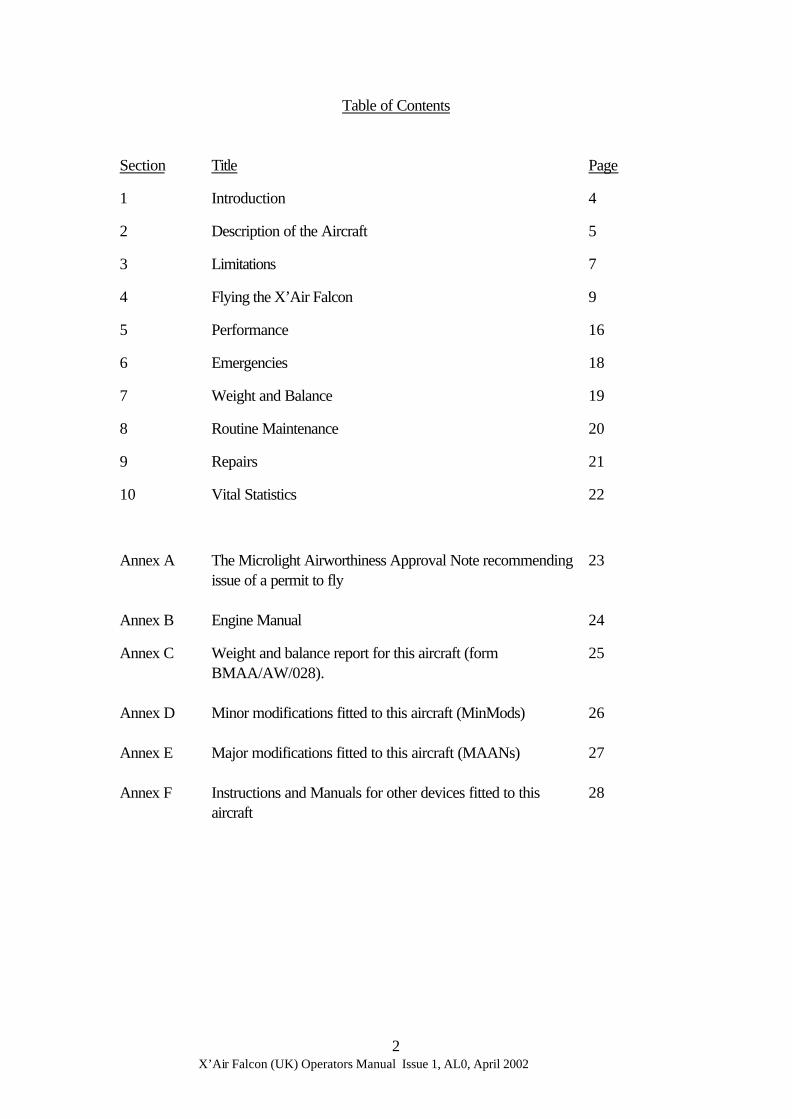
Table of Contents
Section Title Page
1 Introduction 4
2 Description of the Aircraft 5
3 Limitations 7
4 Flying the X’Air Falcon 9
5 Performance 16
6 Emergencies 18
7 Weight and Balance 19
8 Routine Maintenance 20
9 Repairs 21
10 Vital Statistics 22
Annex A The Microlight Airworthiness Approval Note recommending issue of a permit to fly
23
Annex B Engine Manual 24
Annex C Weight and balance report for this aircraft (form BMAA/AW/028).
25
Annex D Minor modifications fitted to this aircraft (MinMods)
26
Annex E Major modifications fitted to this aircraft (MAANs)
27
Annex F Instructions and Manuals for other devices fitted to this aircraft
28
X’Air Falcon (UK) Operators Manual Issue 1, AL0, April 2002
3
TABLE OF AMENDMENTS
Amendment No. Date incorporated Signed Initial Issue April 2002 -
X’Air Falcon (UK) Operators Manual Issue 1, AL0, April 2002
4
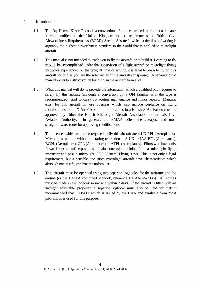
1 Introduction
1.1 The Raj Hamsa X’Air Falcon is a conventional 3-axis controlled microlight aeroplane, it was certified in the United Kingdom to the requirements of British Civil Airworthiness Requirements (BCAR) Section S issue 2; which at the time of writing is arguably the highest airworthiness standard in the world that is applied to microlight aircraft.
1.2 This manual is not intended to teach you to fly the aircraft, or to build it. Learning to fly should be accomplished under the supervision of a light aircraft or microlight flying instructor experienced on the type; at time of writing it is legal to learn to fly on this aircraft so long as you are the sole owner of the aircraft (or spouse). A separate build manual exists to instruct you in building an the aircraft from a kit.
1.3 What this manual will do, is provide the information which a qualified pilot requires to safely fly this aircraft (although a conversion by a QFI familiar with the type is recommended), and to carry out routine maintenance and minor repairs. Manuals exist for this aircraft for use overseas which also include guidance on fitting modifications to the X’Air Falcon; all modifications to a British X’Air Falcon must be approved by either the British Microlight Aircraft Association, or the UK Civil Aviation Authority. In general, the BMAA offers the cheapest and most straightforward route for approving modifications.
1.4 The licenses which would be required to fly this aircraft are a UK PPL (Aeroplanes)-Microlights, with or without operating restrictions. A UK or JAA PPL (Aeroplanes), BCPL (Aeroplanes), CPL (Aeroplanes) or ATPL (Aeroplanes). Pilots who have only flown larger aircraft types must obtain conversion training from a microlight flying instructor and pass a microlight GFT (General Flying Test). This is not only a legal requirement, but a sensible one since microlight aircraft have characteristics which although not unsafe, can bite the unfamiliar.
1.5 This aircraft must be operated using two separate logbooks, for the airframe and the engine (or the BMAA combined logbook, reference BMAA/AW/036). All entries must be made in the logbook in ink and within 7 days. If the aircraft is fitted with an in-flight adjustable propeller, a separate logbook must also be held for that; it recommended that CAP400, which is issued by the CAA and available from most pilot shops is used for this purpose.

X’Air Falcon (UK) Operators Manual Issue 1, AL0, April 2002
5
2 Description of the Aircraft
2.1 Ancestry. The X’Air Falcon is an enhanced X’Air developed by Raj Hamsa in India, based upon the French designed AX3 microlight. The AX3 itself was derived from an American 2-axis controlled ultralight aircraft, the “Weedhopper”. Compared to the earlier X’Air, this Falcon version of the aircraft has a shorter wingspan, 3-position flaps, fully cable-operated ailerons, wider doors, and a modified tail structure. The aircraft is also approved for higher speeds, permitting more powerful engines to be fitted than was possible with the earlier version.
2.2 Construction. The X’Air Falcon is of bolted tubular construction, with aerodynamic surfaces and the fuselage covered with 185 g/m² Dacron polyester fabric. The pod is made from a glass-fibre composite and the transparent windows and doors (if fitted) from “Lexan”. Techniques used are conventional for 3-axis microlights. Most aluminium components are coated with white epoxy paint.
2.3 Flying Controls.
2.3.1 Pitch control is through a conventional elevator controlled by twin control columns in the cockpit. The linkage between them consists of a series of levers and push rods.
2.3.2 Pitch trimming is through a trim tab fitted to one side of the elevator. This is controlled by a lever between the two seats, in the sense forward=nose-down, aft=nose-up. The lever and trim tab are linked by cables under tension through a series of pulleys and runners.
2.3.3 Roll control is through conventional 2/3 span ailerons, controlled by twin control columns in the cockpit. The two ailerons and two sticks are linked by a series of levers, cables and pulleys.
2.3.4 Yaw control is through a conventional rudder (note: this is unlike the AX3 which uses an all-flying fin), controlled by two sets of rudder pedals. Connection is by a series of levers, cables and pulleys.
2.3.5 Braking is effected by twin drum brakes, which provide both stopping and differential steering. These are operated by toe pedals from the left hand seat only. Connection between the brakes and the toe pedals is by Bowden cable.
2.3.6 The nosewheel is steerable and connected to the rudder mechanism in the same sense (push right, yaw right, turn right). Tyres are 4 ply 3.50” x 8” pneumatic.
2.3.7 Flaps are fitted along the inboard 1/3 span of the wing. These may be placed at 0° (up), 21° and 35° (down). The flaps are operated using a handle above and between the pilots heads at the rear of the cabin, which also acts as a flap position indicator. This handle connects via pushrods to the flaps.

X’Air Falcon (UK) Operators Manual Issue 1, AL0, April 2002
6
2.4 Baggage Compartment
2.4.1 There is a small baggage compartment in the panel behind the seats in the cockpit. This is only intended for light items, and is placarded to a maximum of 3kg (6 ½lb). Any load exceeding this can potentially put the aircraft outside it’s permitted CG limits, or cause damage to the aircraft in the event of a hard landing.
X’Air Falcon (UK) Operators Manual Issue 1, AL0, April 2002
7
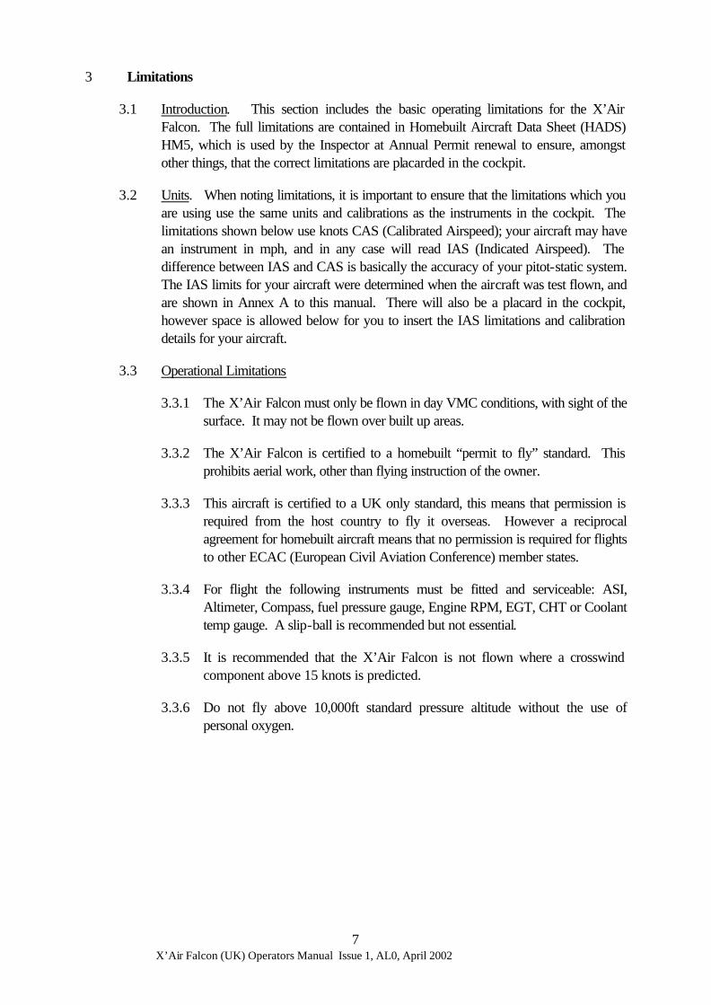
3 Limitations
3.1 Introduction. This section includes the basic operating limitations for the X’Air Falcon. The full limitations are contained in Homebuilt Aircraft Data Sheet (HADS) HM5, which is used by the Inspector at Annual Permit renewal to ensure, amongst other things, that the correct limitations are placarded in the cockpit.
3.2 Units. When noting limitations, it is important to ensure that the limitations which you are using use the same units and calibrations as the instruments in the cockpit. The limitations shown below use knots CAS (Calibrated Airspeed); your aircraft may have an instrument in mph, and in any case will read IAS (Indicated Airspeed). The difference between IAS and CAS is basically the accuracy of your pitot-static system. The IAS limits for your aircraft were determined when the aircraft was test flown, and are shown in Annex A to this manual. There will also be a placard in the cockpit, however space is allowed below for you to insert the IAS limitations and calibration details for your aircraft.
3.3 Operational Limitations
3.3.1 The X’Air Falcon must only be flown in day VMC conditions, with sight of the surface. It may not be flown over built up areas.
3.3.2 The X’Air Falcon is certified to a homebuilt “permit to fly” standard. This prohibits aerial work, other than flying instruction of the owner.
3.3.3 This aircraft is certified to a UK only standard, this means that permission is required from the host country to fly it overseas. However a reciprocal agreement for homebuilt aircraft means that no permission is required for flights to other ECAC (European Civil Aviation Conference) member states.
3.3.4 For flight the following instruments must be fitted and serviceable: ASI, Altimeter, Compass, fuel pressure gauge, Engine RPM, EGT, CHT or Coolant temp gauge. A slip-ball is recommended but not essential.
3.3.5 It is recommended that the X’Air Falcon is not flown where a crosswind component above 15 knots is predicted.
3.3.6 Do not fly above 10,000ft standard pressure altitude without the use of personal oxygen.

X’Air Falcon (UK) Operators Manual Issue 1, AL0, April 2002
8
3.4 Flight Limitations
3.4.1 Never exceed speed, Vne, is 85 kn CAS [ IAS]
3.4.2 Manoeuvring Speed, Va is 70 kn CAS [ IAS]
3.4.3 Flap Limiting speed, VF is 70 kn CAS [ IAS]
3.4.4 Maximum Bank angles are 60° either way.
3.4.5 Maximum Pitch attitudes are 45° nose-up, 30° nose-down.
3.4.6 Normal acceleration limits are +4 / -2g.
3.4.7 At least 55kg (121lbf / 8 stone 9lbf) must be in the cockpit for flight, no more than 90kg (198 lbf / 14 stone 2 lbf) may be carried in each seat.
3.4.8 Maximum Take-off weight is 450 kg.
3.4.9 Aerobatics and deliberate spinning are prohibited.
3.5 Engine Limitations
3.5.1 The limitations for the engine are contained in Annex B, they are also placarded in the cockpit.
IAS Calibration Card for X’Air Falcon G-_______
kn CAS (Calibrated)
30 35 VS
36 Best climb
angle
40 50 51 Best glide, Best
Climb, Approach
60 70 VA VFE
80 85 VNE
IAS (Indicated)
Unless all errors are less than 2 knots, a copy of this calibration card must be displayed in the cockpit near to the ASI

X’Air Falcon (UK) Operators Manual Issue 1, AL0, April 2002
9
4 Flying the X’Air Falcon
4.1 General.
4.2 Pre-Flight Inspection
4.2.1 Engine. Carry out an engine pre-flight inspection following the instructions contained in the Engine Manual at Annex B.
4.2.2 Aircraft. The following is a brief summary of the minimum pre-flight inspection, if you are unsure, it does no harm to increase the number of items on your inspection.
Inside the Cockpit • Ignition switches OFF • Parking brake (if fitted) ON • Condition of choke and choke cable • Condition and security of all flying controls. • Check condition of all instruments • Check harnesses are properly fitted and not frayed. • Check seats are secure. • Check sufficient fuel for the planned flight. • If the aircraft has not flown within 24 hrs, drain a small amount of fuel from
each drain tap using a standard tool and check for water. Starting from the port side, inspect :-
• The fuel hoses from the engine, and the fuel filter. • Condition of door and hinges (if fitted) • Fastenings of the leading edge tube between the two plates. • All of the tubes converging on the footrest. • The stainless steel wing-strut straps • Both wing-strut clevis pins and rings. • The port wing struts and jury struts. • The port wing leading edge • The port wing wingtip fairing
Walk around to the port wing trailing edge, inspect:- • The upper rear compression strut fitting • Compression tube fitting • Through the lower surface inspection panel, check the forward fittings of the
compression tube and drag wires. • Trailing edge attachment clevis pins. • All aileron hinges (nylon bushes should not be greased or oiled) • All clevis pins and wings, aileron cable fastening. • Move the aileron, confirm there is no freeplay between it and the other wing
aileron. • Check the flap structure and hinges ensuring no freeplay and symmetry with
the starboard flap. • Look over the upper and lower wing surfaces for any distortion or damage. • Check the security of the wing centre panel. • Condition of the tyre, undercarriage leg, drag strut and suspension spring.

X’Air Falcon (UK) Operators Manual Issue 1, AL0, April 2002
10
Walking back to the tail, check • All elevator linkages and the pushrod • Condition of all cables (carefully, a broken strand can be very sharp!) - note
that the rudder cables must cross • All clevis pins and rings. • Tension on the fuselage fabric. • Elevator attachment fittings. • Check for excessive freeplay between the elevators • Elevator and rudder hinges • Condition and attachment of the elevator trim tab. • Tension and condition of the tailplane fabric. • Rudder cable shackles • Rear fuselage section fastenings • Aileron and elevator pulley support plate. • Look forward from behind the tail, any airframe distortion should be visible
as an asymmetry.
Walk to the starboard side and check • Starboard elevator hinge • Upper elevator wire fastenings
Moving forward along the fuselage • Fuel filler cap is secure, vents clear, tanks securely attached. • Condition of the tyre, undercarriage leg, drag strut and suspension spring. • Look over the upper and lower wing surfaces for any distortion or damage. • Move the aileron, confirm there is no freeplay between it and the other wing
aileron. • All clevis pins and wings, aileron cable fastening. • All aileron hinges (nylon bushes should not be greased or oiled) • Check the flap structure and hinges ensuring no freeplay and symmetry with
the port flap. • Trailing edge attachment clevis pins. • Through the lower surface inspection panel, check the forward fittings of the
compression tube and drag wires. • Compression tube fitting • The upper rear compression strut fitting • Condition of door and hinges (if fitted)
Walk around to the front of the wing, inspect • The starboard wing wingtip fairing • The starboard wing leading edge • Fastenings of the leading edge tube between the two plates. • All of the tubes converging on the footrest. • The stainless steel wing-strut straps • Both wing-strut clevis pins and rings. • The wing struts and jury struts. • Condition of the pod, windscreen, nosewheel.

X’Air Falcon (UK) Operators Manual Issue 1, AL0, April 2002
11
4.3 Starting. The BMAA standard manual pre-start checks [STAIP] are recommended. The actual starting procedures for a particular engine are contained in Annex B to this manual. The STAIP checks are :- 4.3.1 Aircraft, Crew, Equipment, Secure. 4.3.2 Throttles full and free, and closed. 4.3.3 Area around and behind aircraft clear. 4.3.4 Ignition as required. 4.3.5 Pull, start the engine.
4.4 Taxiing. The aircraft will taxi on whatever course you wish without difficulty using a combination of throttle, toe-brakes and nosewheel steering. In strong winds, keep the stick slightly forward (to keep the nose down) and into wind. It is easiest to turn using the nosewheel steering (rudder pedals), but this can be supplemented for a very tight turn by using the toe brake on the side to which you are turning. The turning circle normally is around 20ft in diameter (at the aircraft centreline).
4.5 Take-off. Prior to take-off, it is recommended that the BMAA standard pre-take-off checks [CHIFTWAP, see below] are used, including a check to ensure that the parking brake (if fitted) is off. The pilot must ensure that the engine has been run successfully at take-off power prior to take-off, and has in any case run for several minutes and the choke is off. You should expect to use significant amounts of rudder to maintain a straight take-off run with a powerful engine fitted.
4.5.1 Controls full and free, Choke off 4.5.2 Harnesses and Helmets (if worn), secure. 4.5.3 Instruments all serviceable, reading correctly. Ignition checked for mag
drop and selected to both. 4.5.4 Fuel on, sufficient for the flight, filter clear of debris, pressure in limits. 4.5.5 Flaps confirm full and free operation, set as required for take-off (0° for
normal take-off, 21° for a short-field take-off). 4.5.6 Trim confirm full and free and set to take-off position. 4.5.7 Wind speed and direction checked, and suitable for safe take-off on selected
runway. 4.5.8 Approach to the selected runway clear of aircraft. 4.5.9 Power checked, and the pilot is satisfied that the aircraft can sustain take-off
power.
4.6 A flapless take-off is conventional. Set the pitch trim to 15°- 30° forward of vertical before take-off. Hold the aircraft straight using the rudder pedals, rotate at 36 kn CAS [ IAS] and the aircraft should fly-off at around 42 knots. It is not advisable to allow the speed below the best climb speed of 51 kn CAS [ IAS] during the climb-out. In crosswinds, the aircraft will feather into wind immediately it is airborne.
4.7 For a short-field take-off, set flaps to 21° and the pitch trim to the vertical position before take-off. Apply full power whilst holding the aircraft on the toe brakes. Release the brakes holding the stick aft to maintain a slightly tail low attitude. Climb at 36 kn CAS [ IAS] (VX) until reaching 200 feet and clear of obstacles, then accelerate to 51 kn CAS [ IAS] (VY) and retract flaps.

X’Air Falcon (UK) Operators Manual Issue 1, AL0, April 2002
12
4.8 Landing. Generally the X’Air Falcon should be landed from an approach speed of about 51 kn CAS [ IAS] with the pitch trimmer set to maintain this speed, although in turbulent conditions, handling can be improved by increasing this by 5-10 knots. Roundout should be initiated around 8-10 ft and hold-off 1-2ft above the runway. Until more detailed operating experience on the aircraft has been gained by the pilot, the pitch trimmer should be set in the vertical position during the pre-landing checks. It is important that speed is not allowed to decay below 42 kn CAS on the latter part of the approach in order to allow sufficient control authority for the flare.
4.9 Short-field Landing. A short field landing may be flown by selecting 35° of flap. Late selection of full flap is recommended thus ensuring a good view of the runway ahead. The pitch trimmer should be set approximately 30° aft of the cruise position before extending flaps. Once you are certain there is sufficient height to reach the landing point, select full flap and maintain an initial approach speed of 51 kn CAS [ IAS], this can be allowed to slow in the flare to 42 kn CAS [ IAS]. It is recommended that the aircraft is flown to the flare with some power left selected, this will increase the available pitch control without significantly increasing the landing distance. In the event of a go-around with full flap, select full power then immediately 21° of flap. Once a positive rate-of climb is established and the aircraft is at-least 200ft agl, it is safe to select 0° of flap and continue to climb out. Beware that it is relatively easy to strike your passenger in the face when operating the flap lever.
4.10 Landing in a Crosswind. Landing with even a small crosswind component can create a significant amount of drift on approach. However by using the crabbed approach technique, with an approach speed of around 60 kn CAS [ IAS], crosswind components of up to 15 knots may be handled without significant difficulty, although the pilot should expect to have to apply considerable concentration and should brief any passenger accordingly. About 20ft above the ground, the rudder should be used to straighten the aircraft, which will cause the into-wind wing to drop, although this may be resisted to some degree with the ailerons, a single wheel landing is inevitable on the into wind wheel. Crosswind components above 15 knots should not be attempted other than by experienced pilots fully familiar with the type.
4.11 During flight testing of the X’Air Falcon, the wing-down approach technique was also investigated. It was concluded that this technique is difficult and unpleasant to fly in the X’Air Falcon and is not recommended.
4.12 Cruise. If setup correctly, the X’Air Falcon should be able to trim at a desired cruise speed ±2 knots, by use of the pitch trimmer, with power set as required. Pilots used to open-cockpit microlights are reminded that the doors (if fitted) may allow the aircraft to be flown slightly out of balance and occasional checks on the slip-ball are worthwhile for efficient flight.

X’Air Falcon (UK) Operators Manual Issue 1, AL0, April 2002
13
4.13 Turning. Turning is conventional for this class of aircraft, with a moderate amount of rudder co-ordination required. The maximum permitted bank angle is 60°, for which quite high back-stick forces, and slightly increased power will be required to maintain a balanced turn. As with any other aircraft, the stall speed will increase with bank angle. However, the nearly full back stick required to stall the X’Air Falcon gives a good warning of the impending stall.
4.14 Flight in Turbulence. The X’Air Falcon has a higher wing-loading than most microlights and hence flies well in turbulence. In turbulence it is best to maintain a reasonably fast cruising speed, which will reduce the effects of gusts and crosswind components; however, do not fly above the manoeuvre speed of 70 kn CAS [ IAS] in turbulence. Below this speed the worst thing a gust can do to you is stall the wing or one of the control surfaces. Above that speed, it is possible for strong gusts to overstress the aircraft.
4.15 Stalling.
4.15.1 A stall can only result from an excessive angle of attack. An aeroplane can be made to stall at any airspeed while being flown in any attitude and configuration. The graph below shows the aircraft stalling speed at standard conditions (1kn/s deceleration, wings level, idle power) at various weights. Stalling speed does not change much with flap setting – although it can be a little lower than predicted at aft CG (especially with full flaps). However, note that this is in knots CAS, and the ASI may under-read considerably at low speeds (see Annex A) giving a much lower apparent stalling speed. Stalling speed may increase slightly with forward CG.
X'Air Falcon Stalling speed with weight
25
27
29
31
33
35
37
300 320 340 360 380 400 420 440
Weight, kgf
Sta
ll sp
eed,
kn
CA
S
X’Air Falcon (UK) Operators Manual Issue 1, AL0, April 2002
14
4.15.2 Standard Stall Recovery. As soon as the stall is recognised:
• Apply full power while easing the control column gently forward. Be ready to counter the effects of power.
• At a safe airspeed proceed into a climb or recover to straight and level flight.
4.15.3 Wings Level, Power Off. The aircraft can safely be stalled at a deceleration
rate of up to 5 kn/s. The pitch attitude does not change much up to the stall. There is little or no pre-stall buffet. Stall is normally marked by full aft stick and the aircraft descending at about 500 fpm or more (what is commonly referred to as ‘mush’). There is normally no stall-break, although a gentle pitch break can be seen with the combination of rapid deceleration rate and aft CG. Rapid deceleration will also cause a higher nose-up attitude at the stall. Recovery is swift upon centralising the stick and applying power. Height loss between stall and recovery, if well executed is around 50ft if power is used. Do not try to recover with power alone, this will pull the nose up into a deeper stall and can cause undemanded wing rocking.
4.15.4 Wings Level, Power On. Characteristics are similar to the power-off stall, however increased power gives a higher nose-up attitude and associated greater pitch break at the stall. Recovery is standard.
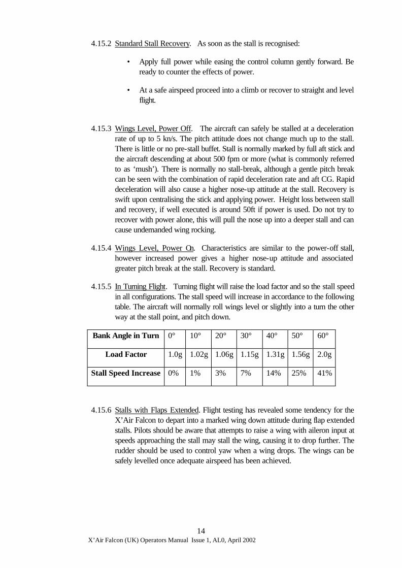
4.15.5 In Turning Flight. Turning flight will raise the load factor and so the stall speed in all configurations. The stall speed will increase in accordance to the following table. The aircraft will normally roll wings level or slightly into a turn the other way at the stall point, and pitch down.
Bank Angle in Turn 0° 10° 20° 30° 40° 50° 60°
Load Factor 1.0g 1.02g 1.06g 1.15g 1.31g 1.56g 2.0g
Stall Speed Increase 0% 1% 3% 7% 14% 25% 41%
4.15.6 Stalls with Flaps Extended. Flight testing has revealed some tendency for the X’Air Falcon to depart into a marked wing down attitude during flap extended stalls. Pilots should be aware that attempts to raise a wing with aileron input at speeds approaching the stall may stall the wing, causing it to drop further. The rudder should be used to control yaw when a wing drops. The wings can be safely levelled once adequate airspeed has been achieved.

X’Air Falcon (UK) Operators Manual Issue 1, AL0, April 2002
15
4.16 Aerobatics. Aerobatics are not permitted in this aircraft.
4.17 Departures from Controlled Flight.
4.17.1 The Spin. Deliberate spinning of the X’Air Falcon is prohibited. However, it is possible through mishandling of the aircraft to inadvertently enter a spin, either through stalling the aircraft in a turn, or by failing to keep the rudder pedals straight at the point of stall. Flight test has shown that this aircraft is extremely spin resistant and will immediately exit from an unintentional spin simply by placing the controls in the central position. An unintentional spin can be recognised by low indicated airspeed, a slow rate of roll and consistent yaw in the same direction followed by a tendency for the aircraft to pitch about 45° nose down. The aircraft has no tendency to violent gyrations and will respond immediately to:
THROTTLE - IDLE CONTROLS - CENTRALISE The aircraft will lose less than 200ft if immediate recovery action is taken, but can lose up to 500 ft if the condition is permitted to develop for one complete turn. When the aircraft has recovered from a spin, it will usually enter a spiral dive. You have full and normal control over the aeroplane during the spiral dive, but it is important to recover from this attitude without either pulling too much g, or exceeding Vne.
4.17.2 Other Departures. Other departures from controlled flight are likely either to
be due to damage to the aircraft, or hazardous flying conditions. In either case, land as soon as possible and examine the aircraft, particularly the flying controls, for any damage.
X’Air Falcon (UK) Operators Manual Issue 1, AL0, April 2002
16
5 Performance.
5.1 The following data were obtained in the original UK prototype, G-BZWC fitted with a 85hp Rotax 912 engine and 68inch Duc Windspoon 3-blade propeller. Changes from this data for your particular aircraft will be at Annex A. When using the data for planning purposes, apply sensible safety factors, such as are contained in CAA Safety Sense leaflet 7B (aircraft performance), part of which is reproduced here by kind permission of the CAA.
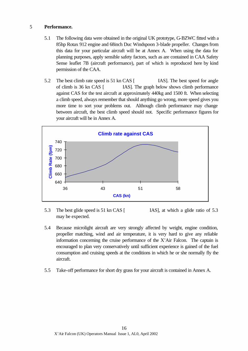
5.2 The best climb rate speed is 51 kn CAS [ IAS]. The best speed for angle of climb is 36 kn CAS [ IAS]. The graph below shows climb performance against CAS for the test aircraft at approximately 440kg and 1500 ft. When selecting a climb speed, always remember that should anything go wrong, more speed gives you more time to sort your problems out. Although climb performance may change between aircraft, the best climb speed should not. Specific performance figures for your aircraft will be in Annex A.
Climb rate against CAS
640
660
680
700
720
740
36 43 51 58
CAS (kn)
Clim
b R
ate
(fp
m)
5.3 The best glide speed is 51 kn CAS [ IAS], at which a glide ratio of 5.3 may be expected.
5.4 Because microlight aircraft are very strongly affected by weight, engine condition, propeller matching, wind and air temperature, it is very hard to give any reliable information concerning the cruise performance of the X’Air Falcon. The captain is encouraged to plan very conservatively until sufficient experience is gained of the fuel consumption and cruising speeds at the conditions in which he or she normally fly the aircraft.
5.5 Take-off performance for short dry grass for your aircraft is contained in Annex A.
X’Air Falcon (UK) Operators Manual Issue 1, AL0, April 2002
17
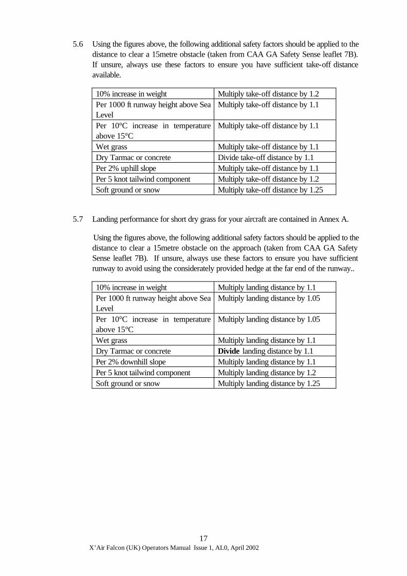
5.6 Using the figures above, the following additional safety factors should be applied to the distance to clear a 15metre obstacle (taken from CAA GA Safety Sense leaflet 7B). If unsure, always use these factors to ensure you have sufficient take-off distance available.
10% increase in weight Multiply take-off distance by 1.2 Per 1000 ft runway height above Sea Level
Multiply take-off distance by 1.1
Per 10°C increase in temperature above 15°C
Multiply take-off distance by 1.1
Wet grass Multiply take-off distance by 1.1 Dry Tarmac or concrete Divide take-off distance by 1.1 Per 2% uphill slope Multiply take-off distance by 1.1 Per 5 knot tailwind component Multiply take-off distance by 1.2 Soft ground or snow Multiply take-off distance by 1.25
5.7 Landing performance for short dry grass for your aircraft are contained in Annex A.
Using the figures above, the following additional safety factors should be applied to the distance to clear a 15metre obstacle on the approach (taken from CAA GA Safety Sense leaflet 7B). If unsure, always use these factors to ensure you have sufficient runway to avoid using the considerately provided hedge at the far end of the runway..
10% increase in weight Multiply landing distance by 1.1 Per 1000 ft runway height above Sea Level
Multiply landing distance by 1.05
Per 10°C increase in temperature above 15°C
Multiply landing distance by 1.05
Wet grass Multiply landing distance by 1.1 Dry Tarmac or concrete Divide landing distance by 1.1 Per 2% downhill slope Multiply landing distance by 1.1 Per 5 knot tailwind component Multiply landing distance by 1.2 Soft ground or snow Multiply landing distance by 1.25

X’Air Falcon (UK) Operators Manual Issue 1, AL0, April 2002
18
6 Emergencies
6.1 Engine Failure Before Take-Off. Close throttle, apply brake, switch off.
6.2 Engine Failure After Take-Off (EFATO). Lower nose to establish an approach speed of at least 51 kn CAS [ IAS] land straight ahead or near to straight ahead, DO NOT ATTEMPT TO TURN BACK from below 500ft. If appropriate select 35° of flap to allow the aircraft to be landed ahead in a shorter distance.
6.3 Engine Failure In Flight. Lower nose, maintain 51 kn CAS [ IAS] best glide speed, select a landing site, make emergency radio call if time permits, as time permits check for possible reasons for engine failure and attempt re-start (e.g. ignition switches, fuel cock, lack of fuel pressure), if field is flat land into wind, otherwise uphill. Apply braking only if it is essential to stop within the distance available, and never before all 3 wheels are on the ground.
6.4 Engine Fire in Flight. Close fuel cock, open throttle fully, make emergency call if time permits, treat as engine failure in flight. Vacate aircraft as soon as possible after landing.
6.5 Fire in the cockpit. Close all ventilation, switch off all electrical devices (not the ignition unless there is an engine fire also), land immediately and vacate the aircraft.
6.6 Emergency Landing on Water. Try to land into wind with as high a nose-up attitude as possible. Before impact, pilot and passenger must be prepared to release their harnesses, it may also be beneficial to release the doors before impact. If wearing lifejackets, do not inflate them until outside the aircraft. Note that it is very hard to judge height above water.
6.7 Emergency Landing in Trees. Ensure harness(es) tight, try for low bushy trees as far as possible. Try to impact with as steep a nose-up attitude as possible.
6.8 Inadvertent Flight in Hail or heavy rain. Turn carb heat on (if fitted), reduce power to avoid propeller damage, fly out of the weather as soon as possible.
6.9 Inadvertent Flight in Icing Conditions. Turn carb heat on (if fitted), fly out of conditions as soon as possible, land as soon as possible.
6.10 Use of Ballistic Parachute (if fitted). Tighten harnesses, fuel cock OFF, ignition OFF, pull handle, make emergency radio call if radio carried. [Note, if a BRS is fitted to this aircraft, the BRS manual will be annexed to this manual.]

X’Air Falcon (UK) Operators Manual Issue 1, AL0, April 2002
19
7 Weight and Balance.
7.1 So long as it is kept within the placarded operating limits, and no unapproved modifications have been made since construction (including the alteration of ballast), the X’Air Falcon can be flown with any permitted fuel, pilot and passenger weights without falling outside of its permitted CG limits. However, pilots should be aware that stick forces and displacements will become lighter with aft CG (typically a lightweight pilot and full fuel) and heavier with forward CG (typically low fuel, pilot and passenger). Flying outside of the permitted CG limits at either extreme is potentially dangerous.
7.2 The X’Air Falcon CG datum is at the mainwheel axle centreline. Measurements are in inches and kg.
7.3 The moment arms of the seats, fuel tank(s) and other items are shown in the Weight and CG report at Annex C.
7.4 The X’Air Falcon will have been weighed when first built, and must be re-weighed at intervals as laid down by the BMAA and CAA (typically every 5 years or when it is modified or repaired).
7.5 Weighing should be carried out by a BMAA 3-axis inspector or Technical Team member. A copy of the W&CG report must be retained in this manual at Annex C. Also at each weighing, details of the weighing must be entered in the aircraft logbook. Full instructions on how to weigh a microlight aircraft are contained in BMAA technical information leaflet TIL 012, and specifically for the X’Air Falcon in HADS HM5.
7.6 The aircraft is fitted with a small baggage compartment behind the seats. This is limited to 3kg, and so long as no load greater than this is placed in there, the aircraft’s handling will remain safe. If this load is exceeded, then the aircraft could become dangerously outside it’s aft CG limit.

X’Air Falcon (UK) Operators Manual Issue 1, AL0, April 2002
20
8 Routine Maintenance.
8.1 Below are the service intervals to be followed for the airframe, for engine maintenance see Annex B.
8.2 It is also permitted for the pilot to adjust the stick position (using the locating holes in front of the seat) and small aileron adjustments may be made at the aileron wire turnbuckles if the aircraft has a natural turn.
L = Lubricate, V = Inspect and replace / repair as required. Item monthly /
50hrs 6 monthly / 150 hrs
annually / 300 hrs
every 3yrs / 900 hrs
Fabric tension, tighten on lacing as required1
V V V V
Fabric condition V V Tyre Pressure (22 psi) V V V V Tyre wear V V V V Brake wear V V V V Front shocks V V V V Main gear shocks V V V V Aileron cables and pulleys2 L L V L V L Flap push rods and joints L L VL VL Throttle and choke cables L L V L V L All cockpit control joints L L V L V L Elevator push rod joints L L V L V L All wiring and hoses V V V Primer bulb V V V Fuel tank V V V Rudder hinges and linkages L V L V L V L Trim tab hinges and linkages L V L V L V L All primary structure and fastenings V V
1 It is vital that under-wing tensioning straps on the wing undersurface are not-overtightened. This can cause the sail to tear. If through mishandling the sail is overtightened and damage results, refer to chapter 9. 2 Nylon Bushes on the aileron hinges should not be greased or oiled
X’Air Falcon (UK) Operators Manual Issue 1, AL0, April 2002
21
9 Repairs
9.1 General. Repairs should either be carried out as described below, or to a scheme approved by the BMAA. After repairs, you should always obtain a “second inspection” from a qualified pilot or (preferably) BMAA inspector after making any repair, who should sign in the logbook that they have inspected the repair and consider it safe. Where this is not possible, draw the repair to the attention of your inspector at the next permit renewal who should oversign your own entry.
9.2 Sail Repairs. Sail (flexible surface) repairs must be carried out in accordance with BMAA Technical Information Leaflet TIL 015.
9.3 Repairs to tubular structure, springs, pulleys, cables, bolts, nuts, etc. Any damaged such parts must not be repaired and the aircraft must not be flown once the damage has been identified. Identical replacement parts must be fitted before any further flight, and their installation inspected and signed-off in the logbook by a BMAA inspector. The invoice (legally referred to as the certificate of conformity) for the parts fitted must kept with the aircraft logbook. If it is not possible to obtain replacement parts, consult the BMAA Technical Office for advice.
9.4 Repairs to the Engine. These should be carried out in accordance with the maintenance manual for the engine fitted.
9.5 Repairs to Instruments. Microlight aircraft instruments are not usually repairable and should be replaced.
9.6 Repairs to Fuel Hose. Any fuel hose which is found to be cracked or damaged must not be repaired. Replace it with at least automotive quality (preferably aircraft or fire-retardant boat use) re-enforced rubber fuel hose. It is not advised that transparent fuel hose is used, and PVC hose must not be used with fuel under any circumstances. Take care not to over-tighten cable ties used to secure hose, since this can cause a flow restriction.
9.7 Damaged Wiring. Replace with fireproof or fire resistant wiring of the same or higher current rating, secured in the original manner.
9.8 Repairs to Batteries. (If fitted), a damaged battery must be replaced and all surrounding structure thoroughly inspected for acid damage.
9.9 Repairs to Tyres. An inner tube puncture may be repaired. If there is damage to the tyres which shows the inner canvas, replace the tyre in question.
9.10 Damage to the Fuel Tank. The fuel tank should be drained and removed from the aircraft. If the tank is judged to be repairable, a layered glass-fibre repair may be made and then inspected by a BMAA Inspector qualified for composites, who must also conduct a 1.5psi pressure test to ensure that the tank does not leak. If the tanks become impossible to see the fuel level through, either the starboard tank must be replaced with a new item, or a separate fuel gauge may be fitted (which must be approved by BMAA modification).
X’Air Falcon (UK) Operators Manual Issue 1, AL0, April 2002
22
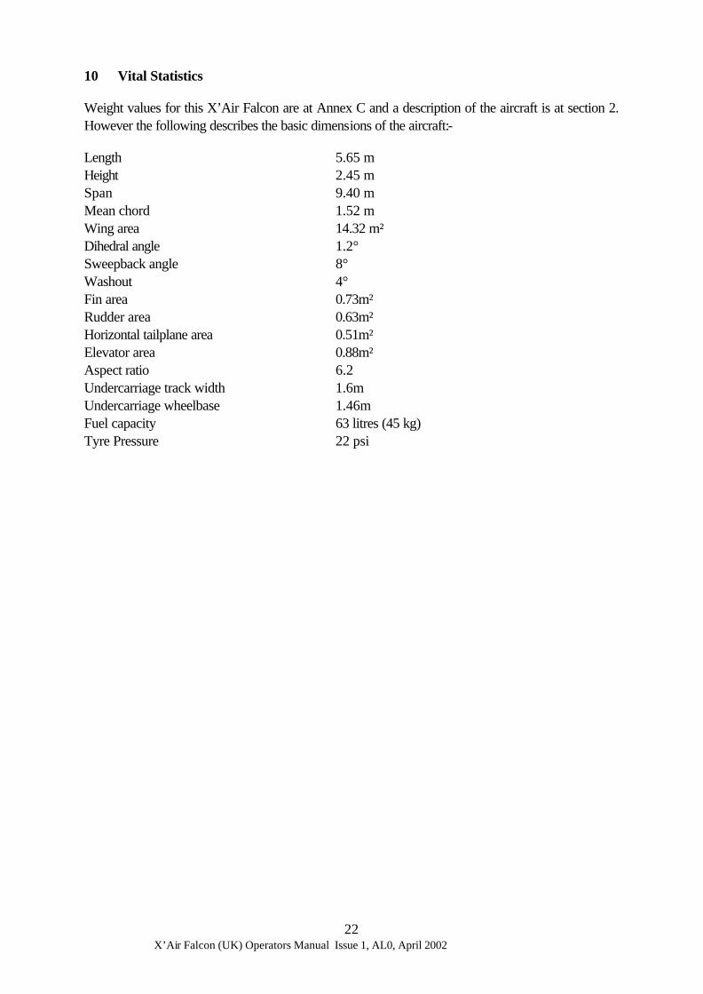
10 Vital Statistics
Weight values for this X’Air Falcon are at Annex C and a description of the aircraft is at section 2. However the following describes the basic dimensions of the aircraft:-
Length 5.65 m Height 2.45 m Span 9.40 m Mean chord 1.52 m Wing area 14.32 m² Dihedral angle 1.2° Sweepback angle 8° Washout 4° Fin area 0.73m² Rudder area 0.63m² Horizontal tailplane area 0.51m² Elevator area 0.88m² Aspect ratio 6.2 Undercarriage track width 1.6m Undercarriage wheelbase 1.46m Fuel capacity 63 litres (45 kg) Tyre Pressure 22 psi

X’Air Falcon (UK) Operators Manual Issue 1, AL0, April 2002
23
ANNEX A
MAAN RECOMMENDING ISSUE OF A PERMIT TO FLY
The approval MAAN for this aircraft is to follow this page.

X’Air Falcon (UK) Operators Manual Issue 1, AL0, April 2002
24
ANNEX B
ENGINE MANUAL
The operators and maintenance manual for the engine fitted to this aircraft is to follow this page.

X’Air Falcon (UK) Operators Manual Issue 1, AL0, April 2002
25
ANNEX C
WEIGHT AND BALANCE REPORT
Forms BMAA/AW/028 completed for this aircraft are to follow this page.
X’Air Falcon (UK) Operators Manual Issue 1, AL0, April 2002
26
ANNEX D
MINOR MODIFICATIONS FITTED TO THIS AIRCRAFT SINCE INITIAL PERMIT ISSUE
Minor modification approval sheets are to follow this page
Minmod No. Description Sign and date incorporated
X’Air Falcon (UK) Operators Manual Issue 1, AL0, April 2002
27
ANNEX E
MAJOR MODIFICATIONS FITTED TO THIS AIRCRAFT SINCE INITIAL PERMIT ISSUE
BMAA MAANs and CAA AANs (other than the original approval MAAN) are to follow this page.
MAAN / AAN No.
Issue Description Sign and date incorporated

X’Air Falcon (UK) Operators Manual Issue 1, AL0, April 2002
28
ANNEX F
INSTRUCTIONS AND MANUALS FOR OTHER DEVICES FITTED TO THIS AIRCRAFT
No. Description Issue or date
Approval Mod No., or original equipment
F1 F2 F3 F4 F5 F6 F7 F8 F9 F10 F11 F12 F13 F14 F15 F16 F17