Embed Size (px)
Citation preview

PART NUMBER 6T70-ZIP QUICK GUIDE
Separator Plate
6T70 (Gen. 1) Lower Valve Body
6T70 (Gen. 1) Upper Valve Body
1
1
1
2
4
5
1
1
1
3
16
NOTE: Drill and aluminum plugs for this step not shown.
CAUTIONCAUTIONCAUTIONCAUTION
CAUTION!: Ensure shuttle valve is installed with blind bore facing
inboard and rounded, closed end facing the end plug. 8*
NOTE: Reference pages 2, 3 and 4 in the technical booklet for installation details. *Patent Pending
7 Replace nine OE checkballs.
©2016 Sonnax Industries, Inc. 6T70-ZIP-Guide 06-17-16
800-843-2600 • 802-463-9722 • F: 802-463-4059 • www.sonnax.com Page 1
GM 6T70 (GEN. 1), 6T75 (GEN. 1)ZIP KIT®
Parts are labeled here in order of installation. See other side of sheet for details on Zip Kit contents.
installation Diagram
In addition to general rebuilding tips and technical information, the technical booklet included in this kit contains vacuum testing and additional repair options for higher mileage units or for repairing specific complaints which are beyond the scope of this kit.

GM 6T70 (GEN. 1), 6T75 (GEN. 1) ZIP KIT® Quick Guide
Step Replace Seven OE End Plugs
Place O-ring into end plug groove. Lubricate with Sonnax Slippery Stick O-LUBE and roll on bench to size.
Packaging Pocket 1
• End Plug (7) • O-Rings (11) 4 extra
Step Replace OE Isolator Valve & Spring
Place one O-ring into plug groove and one O-ring into isolator valve goove. Lubricate with Sonnax Slippery Stick O-LUBE and roll on bench to size.
Packaging Pocket 2
• End Plug • Valve • Spring • O-Rings (3) 1 extra
Step Replace OE TCC Regulator Apply Valve Bore Lineup
Remove and discard all OE components except the end clip. Save OE end clip for reuse.
CAUTIONCAUTIONCAUTIONCAUTION
CAUTION: Ensure shuttle valve is installed with blind bore facing inboard and rounded, closed end facing the end plug.
Packaging Pocket 3
• TCC Regulator Apply Valve • Spring • Shuttle Valve• End Plug • O-Rings (2) 1 extra
Step Replace OE Actuator Feed Limit (AFL) Valve Lineup
Remove and discard OE valve and spring. Keep outboard OE retainer for reuse. Install Sonnax sleeve and valve as illustrated. Secure sleeve into bore by installing Sonnax clip into sleeve groove at inboard port. Install Sonnax spring and secure all components into the bore with OE retainer.
Packaging Pocket 4
• Sleeve • Valve • Spring • Clip
1
2
3
CAUTIONCAUTIONCAUTIONCAUTION
4
Step Replace OE 4-5-6 Accumulator Piston & Springs
Remove and discard OE piston and springs. Keep OE retainer for reuse. Place O-ring into piston groove. Lubricate with Sonnax Slippery Stick O-LUBE and roll on bench to size.
Packaging Pocket 5
• Accumulator Piston • Large Spring • Small Spring• O-Rings (2) 1 extra
Step Block AFL Balance PortDrill indicated separator plate orifice with included .062" dia. drill. Remove any burrs. Insert .062" dia. aluminum plug into drilled hole and peen in place on both sides of plate. Ensure plate will sit flush on both castings. Replace OE checkballs.
Packaging Pocket 6
• Drill (.062" dia.) • Aluminum Plugs (2) 1 extra
Step Replace OE CheckballsPackaging Pocket 7
• Checkballs, .250" dia. (9)
Step Replace OE Pressure Switch Laminate Discs & Seals
Reference pages 2, 3 and 4 in the technical booklet for installation details.
Packaging Pockets 8–10
• Seals (5) 1 Extra • Laminate Discs (5) 1 Extra • Seal Installer* • Piston* • Plunger*• Laminate Installation Tool*
*NOTE: These components are patent pending.
5
6
7
8
Zip Kit Contents & Installation Steps
©2016 Sonnax Industries, Inc. 6T70-ZIP-Guide 06-17-16
800-843-2600 • 802-463-9722 • F: 802-463-4059 • www.sonnax.com Page 2

Valve Body ID & Tech TipsAdaptive LearningThe 6T70 and 6T75 is equipped with several adaptive learning strategies. After valve body service the existing adaptive values will need to be erased. Then, a “Fast Learn” process should be performed. Reference GM Material for proper “Fast Learn” process.
Clutch Apply Chart
Gear1-2-3-4 Clutch
3-5 Clutch
4-5-6 Clutch
2-6 Clutch
Low & Reverse Clutch
Low & Reverse One-Way Clutch
Park X
Reverse X X
Neutral X
1st Breaking X X Holding
Driv
e
1st X Holding
2nd X X
3rd X X
4th X X
5th X X
6th X X
Figure 2
Solenoid Apply Chart
Gear
Solenoid
Shift Solenoid 1
Shift Solenoid 2
1-2-3-4 PC Solenoid 5 NL
2-6 PC Solenoid 4 NL
3-5 Rev. PC Solenoid 2 NH
Low Reverse 4-5-6 PC
Solenoid 3 NHPark X X X
Reverse X X X
Neutral X X X
1st Breaking X X X X
Driv
e
1st X X
2nd X X X
3rd X X X
4th X X X
5th X X X
6th X X X
Figure 3
KEY: X = On/Applied
Figure 16T70 (Gen. 1) Mechatronic Assembly
TEHCM
Zip Kit Instructions1. Valve Body Removal from Case
a. Disconnect shift position switch.
b. Disconnect input speed sensor (ISS).
c. Disconnect output speed sensor (OSS).
d. Remove four control valve body 80mm bolts (yellow). Position TCU spring retainer to the side.
e. Remove the remaining seven control valve bolts (Figure 4).
f. Remove TEHCM assembly.
g. Remove solenoid filter plate (Figure 6) from the back of the TEHCM assembly. Discard and replace, as the seals take a set and will leak if reused.
h. Remove the ten control valve body bolts (Figure 7).
i. Remove manual shaft detent assembly.
j. Remove control valve body from transmission.
2. Disassembly (Figure 8)Remove the eight control valve body assembly bolts.
3. InstallationInstall Zip Kit parts as shown on diagram of separate quick guide sheet included in this Zip Kit. Sonnax recommends vacuum testing critical wear areas not covered by this kit to determine whether additional Sonnax parts are required (see page 5 & 6).
4. Reassembly Reassemble valve body and reinstall the eight control valve body assembly bolts (Figure 8). Tighten to 106 in-lb (Figure 5).
5. Valve Body Reinstall to Casea. When reinstalling the manual shaft detent assem-
bly, ensure proper alignment with the lever. Contact with the valve body can cause improper engagement with the lever (Figure 7).
b. Reinstall the control valve body and manual shaft detent assembly into the transmission using 10 bolts (Figure 7). Hand tighten, then tighten in the indicated sequence to 106 lb-in (Figure 5).
c. Install new solenoid filter plate (Figure 6).d. Reinstall TEHCM assembly and TCU spring
retainer.
GM 6T70 (GEN. 1), 6T75 (GEN. 1)ZIP KIT®
PART NUMBER 6T70-ZIP INSTALLATION & TESTING BOOKLET
©2016 Sonnax Industries, Inc. 6T70-ZIP-Booklet 06-17-16
800-843-2600 • 802-463-9722 • F: 802-463-4059 • www.sonnax.com Page 1

GM 6T70 (GEN. 1), 6T75 (GEN. 1) ZIP KIT® Installation & Testing Booklet
06-17-16 6T70-ZIP-Booklet ©2016 Sonnax Industries, Inc.
Page 2 800-843-2600 • 802-463-9722 • F: 802-463-4059 • www.sonnax.com
TIME TESTED • INDUSTRY TRUSTED
Figure 66T70 (Gen. 1) Filter Plate
Figure 76T70 (Gen. 1) Valve Body
4 102
7
58
13
6
9
Figure 86T70 (Gen. 1) Valve Body
5. Valve Body Reinstall to Case, continued
e. Reinstall and hand tighten the 11 bolts, then tighten in the indicated sequence to 106 in-lb (Figure 4).
f. Reconnect shift position switch.g. Reconnect intput speed sensor (ISS).h. Reconnect output speed sensor (OSS).
Figure 4
1
2
346
58
10
911
7
Output Speed Sensor Connector
TEHCM
TCU TCU Spring RetainerShift Position Switch Connector
Input Speed Sensor Connector
Installing Sonnax Pressure Switch Rebuild Kit NOTE: Before installing kit, test switches to verify proper electrical operation. Kit repairs laminate disc and seal failures only; it will not rectify electrical breakdown.
1. Testing Switchesa. Locate 5-pin pressure switch terminals (Figure 9). Ground
pin is all the way to the left; moving to the right, each pin is power supply for an individual switch (Figure 10). Place negative ohmmeter lead on ground pin and positive lead on a power supply pin. At rest, each switch should read between .5 and 10 ohms. Depressing switch with pencil eraser should result in O.L. reading.
b. If testing is successful, proceed with kit installation.
6T70 Disassembly & Reassembly BoltsBolt Color Code Bolt Length Torque
Orange 35mm
106 in-lb
Green 42mm
Pink 55mm
Blue 64mm
Red 95mm
Yellow 80mm
Figure 5

GM 6T70 (GEN. 1), 6T75 (GEN. 1) ZIP KIT®
©2016 Sonnax Industries, Inc. 6T70-ZIP-Booklet 06-17-16
800-843-2600 • 802-463-9722 • F: 802-463-4059 • www.sonnax.com Page 3
TIME TESTED • INDUSTRY TRUSTED
2. Remove OE Seals & Discs a. Using small screwdriver, remove OE switch seals
and discard (Figure 11).
b. Using small pick, gently remove OE laminate discs and discard (Figure 12).
c. With laminate disc removed, OE plastic piston is exposed; piston is easily removed with pick for cleaning (Figure 13). Using low air pressure (30psi), blow any debris out of switch cavities. Clean and reinstall piston.
3. Installation & Assemblya. Gently form Sonnax laminate disc
into inverted “U” shape and insert into bottom of switch cavity. Leading edge of laminate disc should slide into small groove at bottom of switch bore (Figures 14, 15 & 16).
b. Insert Sonnax laminate installation tool over disc with “heel” toward top of switch bore and “toe” tucked under groove at bottom of bore (Figures 17
& 18).
c. Gently press down on disc with tool ‘foot’ and rotate tool 360⁰ until all of laminate disc edge is secure under bore groove (Figure 19).
Figure 9
Figure 10
Ground Pin
Individual Switch Power Supply
Figure 14 Figure 16
Figure 12
Remove laminate disc.
Figure 11
Remove seal.
Figure 15
Insert under groove.
Figure 17
Toe
Heel
Figure 18
Tuck toe under bore groove.
Heel
Figure 19
Rotate tool foot around bore groove.
Figure 13
Remove piston, clean cavity, reinstall piston.

GM 6T70 (GEN. 1), 6T75 (GEN. 1) ZIP KIT® Installation & Testing Booklet
06-17-16 6T70-ZIP-Booklet ©2016 Sonnax Industries, Inc.
Page 4 800-843-2600 • 802-463-9722 • F: 802-463-4059 • www.sonnax.com
TIME TESTED • INDUSTRY TRUSTED
Figure 20
Ensure disc is centered, edges under bore groove. CORRECT
Figure 21
INCORRECT
Figure 29Figure 27
Figure 30 Figure 31
CORRECT
Figure 32
INCORRECT
Figure 28
PressPistonDown
Piston
Seal Installer
Figure 24
Figure 22
Piston
Seal Installer
Drop piston into seal installer.
Figure 25Seal Plunger
Figure 26
Push
3. Installation & Assembly, continued
d. Ensure laminate disc is centered, covering entire bore opening without gaps (Figures 20 & 21).
e. Install Sonnax piston into Sonnax seal installer as indicated (Figures 22 & 23).
f. Lubricate all sides of Sonnax seal. Insert seal flush into seal installer (Figure 24).
g. Push seal into seal installer assembly using Sonnax seal plunger until plunger bottoms seal in tool (Figures 25 & 26).
h. Insert piston/seal installer assembly into switch bore (Figure 27).
i. While holding seal installer in place, push piston downward (Figures 28, 29
& 30). The seal installer will rise out of bore as seal sets into place.
j. Inspect installed seal to ensure flush fit (Figures 31 & 32).
Figure 23
Seal Installer
Piston
Piston will bottom out in seal installer.
Seal
Piston
Seal Installer
Seal

GM 6T70 (GEN. 1), 6T75 (GEN. 1) ZIP KIT®
©2016 Sonnax Industries, Inc. 6T70-ZIP-Booklet 06-17-16
800-843-2600 • 802-463-9722 • F: 802-463-4059 • www.sonnax.com Page 5
TIME TESTED • INDUSTRY TRUSTED
Critical Wear Areas & Vacuum Test Locations NOTE: OE valves are shown in rest position and should be tested in rest position unless otherwise indicated. Test locations are pointed to with an arrow. Springs are not shown for visual clarity. Low vacuum reading indicates wear and Sonnax parts noted for replacement. For specific vacuum test information, refer to individual part instructions included in kits and available at www.sonnax.com.
Upper Valve Body • 6T70 (Gen. 1)
20
25
15
0
10
5
30VACUUMTEST
Plug port on back.
3-5 Reverse Clutch Regulator Valve• Burnt 3-5 Reverse clutch • Delayed Reverse• 3rd & 5th Shift complaints • 2-3 & 4-5 Shift flareReplace with Sonnax Part No.124740-26K (1.35 Ratio) Requires F-124740-TL26 & VB-FIX124740-21K (1.83 Ratio) Requires F-124740-TL21 & VB-FIX
TCC Regulator Apply Valve• No TCC/slip, soft apply• Harsh TCC applyReplace with Sonnax Part No.124740-24K Requires F-124740-TL24 & VB-FIX
Plug port on back.
2-6 Clutch Regulator & Gain Valve• Burnt 2-6 clutch• 2nd & 6th Shift complaints• 1-2 & 5-6 Shift flareReplace with Sonnax Part No.124740-17K Requires F-124740-TL17 & VB-FIX
Isolator Valve• Low line pressure• Slipping/Burnt clutches• Soft shifts/applyReplace with Sonnax Part Nos.124740-16 (Spring Only)124740-03K* (Isolator Valve Kit)
TCC Control Valve• Incorrect TCC apply/release• Transmission overheat• Low/No cooler/lube flowReplace with Sonnax Part No. 124740-14K Requires F-124740-TL14 & VB-FIX
Clutch Select Solenoid Valve #3• Various shift complaints• Shift related trouble codes
Plug port on back.
L/R Overdrive Clutch Regulator Valve• Burnt L/R and/or 4-5-6 clutch• 4-5-6 Shift complaints• Delayed Reverse• 3-4 Shift flare
Plug port on back.
Clutch Select Solenoid Valve #2• Various shift complaints• Shift related trouble codes
Pressure Regulator Valve• High/Low line pressure• Slipping/Burnt clutches• Harsh/Soft shifts/apply• Transmission overheat• Low/No cooler/lube flowReplace with Sonnax Part No.124740-12K Requires F-124740-TL12 & VB-FIX
O-Ringed End Plug Kit• Burnt clutches/brakes• Various shift complaints
NOTE: Vacuum test end plugs at outboard port while sealing bore opening with thumb.
Replace with Sonnax Part No.124740-02K* NOTE: Several Locations = *Part numbers with an asterisk (*) are included in this Zip Kit.

GM 6T70 (GEN. 1), 6T75 (GEN. 1) ZIP KIT® Installation & Testing Booklet
06-17-16 6T70-ZIP-Booklet ©2016 Sonnax Industries, Inc.
Page 6 800-843-2600 • 802-463-9722 • F: 802-463-4059 • www.sonnax.com
TIME TESTED • INDUSTRY TRUSTED
Critical Wear Areas & Vacuum Test Locations NOTE: OE valves are shown in rest position and should be tested in rest position unless otherwise indicated. Test locations are pointed to with an arrow. Springs are not shown for visual clarity. Low vacuum reading indicates wear and Sonnax parts noted for replacement. For specific vacuum test information, refer to individual part instructions included in kits and available at www.sonnax.com.
Lower Valve Body • 6T70 (Gen. 1)
20
25
15
0
10
5
30VACUUMTEST
Actuator Feed Limit Valve• Harsh shifts • Low clutch pressure• No/Slipping shifts• Solenoid coresReplace with Sonnax Part No.124740-01 Requires
F-104740-TL12 & VB-FIX
Plug port on back.
4-5-6 Clutch Boost Valve• Burned 4-5-6 clutch• 4-5-6 Shift complaints• 3-4 FlareReplace with Sonnax Part No.144740-23 Requires
F-144740-TL22 & VB-FIX
4-5-6 Clutch Accumulator Piston• Harsh 3-4• 3-4 Flare• Burned 4-5-6 clutchReplace with Sonnax Part No.124740-04K*
Plug port on back.
1-2-3-4 Clutch Boost Valve• Burned 1-2-3-4 clutch• Delayed Forward• 1-2-3-4 Shift complaintsReplace with Sonnax Part No.144740-23Requires F-144740-TL22 & VB-FIX
1-2-3-4 Clutch Regulator Valve• Burned 1-2-3-4 clutch• Delayed Forward• 1-2-3-4 Shift complaints
Plug port on back.
3-5 Reverse Clutch Boost Valve• Burned 3-5 Reverse clutch• Delayed Reverse• 3rd & 5th Shift complaints• 2-3 & 4-5 Shift flareReplace with Sonnax Part No.144740-23 Requires F-144740-TL22 & VB-FIX
*Part numbers with an asterisk (*) are included in this Zip Kit.
GM 6T70 (GEN. 1), 6T75 (GEN. 1) ZIP KIT®
©2016 Sonnax Industries, Inc. 6T70-ZIP-Booklet 06-17-16
800-843-2600 • 802-463-9722 • F: 802-463-4059 • www.sonnax.com Page 7
TIME TESTED • INDUSTRY TRUSTED
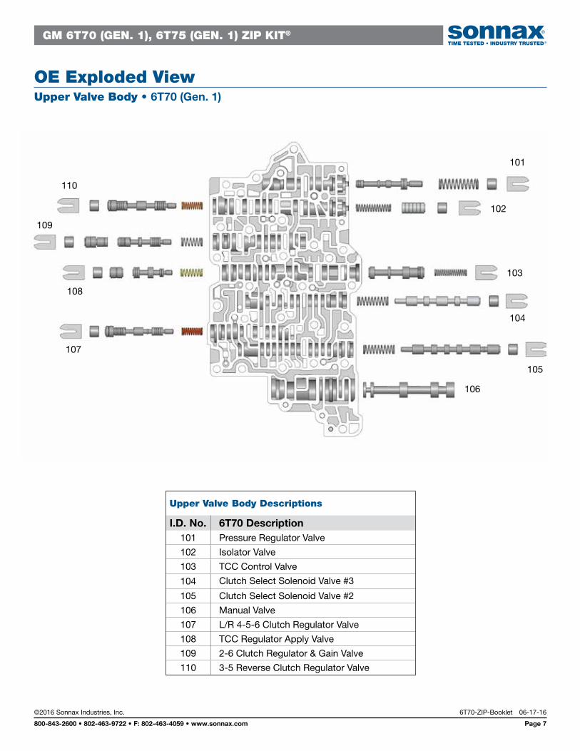
OE Exploded ViewUpper Valve Body • 6T70 (Gen. 1)
Upper Valve Body Descriptions
I.D. No. 6T70 Description101 Pressure Regulator Valve
102 Isolator Valve
103 TCC Control Valve
104 Clutch Select Solenoid Valve #3
105 Clutch Select Solenoid Valve #2
106 Manual Valve
107 L/R 4-5-6 Clutch Regulator Valve
108 TCC Regulator Apply Valve
109 2-6 Clutch Regulator & Gain Valve
110 3-5 Reverse Clutch Regulator Valve
110
101
109
102
108
107
106
105
104
103

GM 6T70 (GEN. 1), 6T75 (GEN. 1) ZIP KIT® Installation & Testing Booklet
06-17-16 6T70-ZIP-Booklet ©2016 Sonnax Industries, Inc.
Page 8 800-843-2600 • 802-463-9722 • F: 802-463-4059 • www.sonnax.com
TIME TESTED • INDUSTRY TRUSTED
OE Exploded ViewLower Valve Body • 6T70 (Gen. 1)
Lower Valve Body Descriptions
I.D. No. 6T70 Description201 4-5-6 Clutch Accumulator Piston
202 1-2-3-4 Clutch Boost Valve
203 1-2-3-4 Clutch Regulator Valve
204 4-5-6 Clutch Boost Valve
205 Actuator Feed Limit Valve
206 3-5 Reverse Clutch Boost Valve
201
206
202
205
204
203