Embed Size (px)
Citation preview
Copyright 2003 Carrier Corporation Form FX4B-2PD
ProductData
FX4BDirect Expansion
Fan Coilwith Puron® Refrigerant
Sizes 018, 030 thru 060
Air Handling Technology At Its Finest
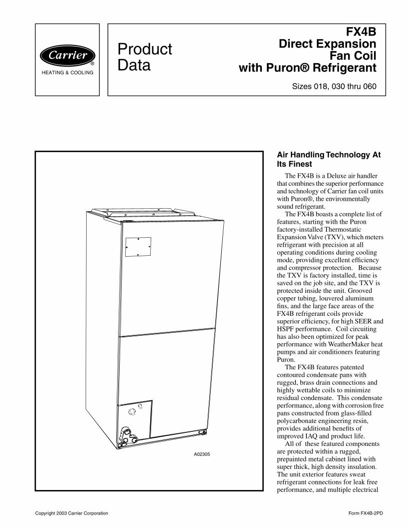
The FX4B is a Deluxe air handler that combines the superior performance and technology of Carrier fan coil units with Puron®, the environmentally sound refrigerant.
The FX4B boasts a complete list of features, starting with the Puron factory-installed Thermostatic Expansion Valve (TXV), which meters refrigerant with precision at all operating conditions during cooling mode, providing excellent efficiency and compressor protection. Because the TXV is factory installed, time is saved on the job site, and the TXV is protected inside the unit. Grooved copper tubing, louvered aluminum fins, and the large face areas of the FX4B refrigerant coils provide superior efficiency, for high SEER and HSPF performance. Coil circuiting has also been optimized for peak performance with WeatherMaker heat pumps and air conditioners featuring Puron.
The FX4B features patented contoured condensate pans with rugged, brass drain connections and highly wettable coils to minimize residual condensate. This condensate performance, along with corrosion free pans constructed from glass-filled polycarbonate engineering resin, provides additional benefits of improved IAQ and product life.
All of these featured components are protected within a rugged, prepainted metal cabinet lined with super thick, high density insulation. The unit exterior features sweat refrigerant connections for leak free performance, and multiple electrical
A02305
2
entry for both high and low voltage service, for quality appearance in all installation applications.
Further versatility of the FX4B is made possible by the multipoise
(horizontal left and right, upflow and downflow) design which makes Carrier fan coils the benchmark for the industry.
Environmentally Sound operation;
high levels of efficiency; quality appearance; ease of installation; reliable, compressor-protecting performance: That’s the FX4B — in a class all of its own.
Features
Environmentally Sound Refrigerant Technology
•
Puron®, chlorine-free, non-ozone depleting refrigerant
•
Thermostatic Expansion Valve (TXV) designed to maximize performance with Puron
Energy Efficient Operation
•
12.00 to 13.00 SEER with the industry’s first Puron Heat Pump
•
3-speed motors for flexible, efficient airflow performance
Airflow and Sound Technology
• Logarithmic spiral blower housings for high blower efficiency and quiet operation• Diffuser air discharge section for high airflow efficiency and quiet, smooth operation• High duct static capability with the high speed tap• Unique cabinet design that meets new stringent regulations for air leakage. Meets requirements of a 2% cabinet leakage rate
when tested at 1.0 inches of static pressure
Condensate Control and Disposal Technology
• Minimal standing water - less microbial growth for improved IAQ and reduced condensate line clogging and related condensate leakage
• Condensate fittings relocated away from turbulent airflow patterns at the blower entrance for improved condensate control performance
• Overflow feature for slope coil units allows condensate to exit the unit without damage to the product under clogged primary and secondary line conditions
• Tested for condensate disposal at conditions much more severe than those required by ARI• Primary and secondary drain connections to comply with HUD• All pans constructed of glass-filled polycarbonate engineering resin material• High density, 1 inch thick cabinetry insulation with vapor barrier• Cabinet construction features innovations designed to reduce cabinet sweating• Prepainted galvanized sheet metal cabinet
Heat Transfer Technology
• Grooved copper tubing• Lanced sine wave aluminum fins• Discreet refined counterflow refrigerant circuitry • Bi-flow hard shut-off TXV metering device
Quality Assisting, Ease of Installation and Service Features
• All units multipoise • Provision made for suspending from roof or ceiling joists• Modular cabinet on 060 unit• Sweat connections for leak free service• Multiple electrical entry on for application flexibility (high and low voltage)• Inspection plate on A-coil models for quick coil cleanliness inspection• Cabinet construction features innovations designed to prevent cabinet sweating
Controls and Electrical Features
• Blower-off delay built in (defeatable) • Easy plug connection for quick installation of accessory heater packages• 40 VA 208/230 volt transformer• Replaceable 5-amp blade-type auto fuse protects against transformer secondary short
Filter Features
• Factory supplied filter, cleanable polyester filter media• Filter “springs” out for easy access - no tools required• Newly improved filter rack area (bottom flange size increased for improved filter positioning)• Newly improved filter rack area - filter door insulation added for an improved air seal
3
MANUFACTURER
CERTI
FIE
DT
OA
RI A
SCOMPLYING WITH
ARI S
TA
ND
AR
D24
0
UNITARYHE
AT PUMP
EQ
UIP
ME
NT
®
MANUFACTURER
CERTI
FIE
DT
OA
RI A
SCOMPLYING WITH
ARI S
TA
ND
AR
D21
0
UNITARY
AIR
CONDITIONING
EQ
UIP
ME
NT
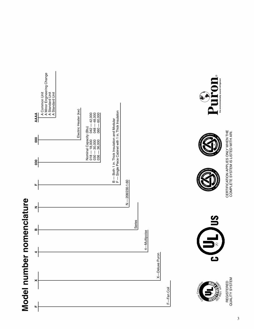
Mo
del
nu
mb
er n
om
encl
atu
re
FX
4B
NF
030
000
AA
AA
A C
omm
on U
nit
A M
inor
Eng
inee
ring
Cha
nge
A S
tand
ard
Uni
tA
Sta
ndar
d U
nit
Ele
ctric
Hea
ter
(kw
)
Nom
inal
Cap
acity
(B
tu)
018
— 1
8,00
004
2 —
42,
000
030
— 3
0,00
004
8 —
48,
000
036
— 3
6,00
006
0 —
60,
000
B —
Bot
h 1
in. T
hick
Insu
latio
n an
d M
odul
arF
— S
ingl
e P
iece
Cab
inet
with
1 in
. Thi
ck In
sula
tion
N —
208
/230
-1-6
0
Ser
ies
4—M
ultip
oise
X—
Del
uxe
Pur
on
F—
Fan
Coi
l
CE
RT
IFIC
ATIO
N A
PP
LIE
S O
NLY
WH
EN
TH
EC
OM
PLE
TE
SY
ST
EM
IS L
IST
ED
WIT
H A
RI.
RE
GIS
TE
RE
DQ
UA
LIT
Y S
YS
TE
M
4
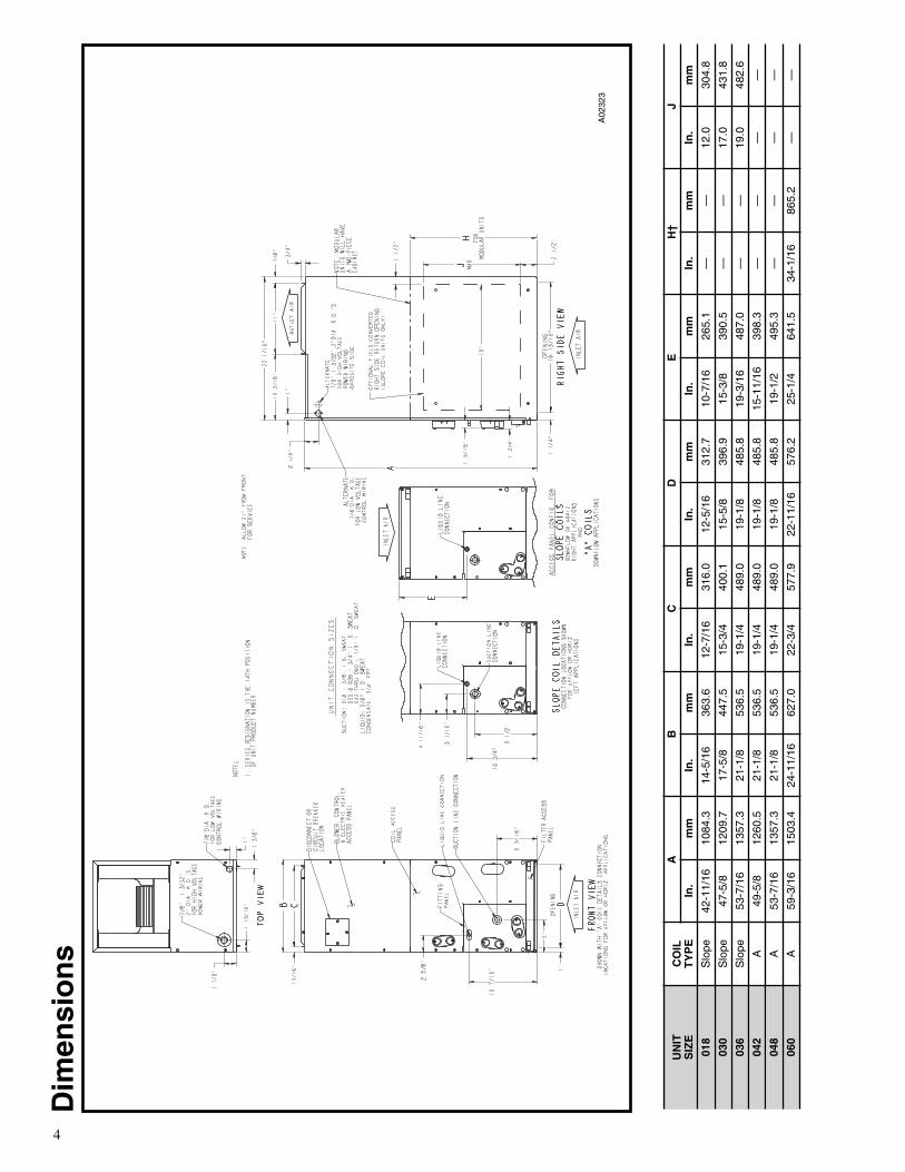
Dim
ensi
on
s
A02
323
UN
ITS
IZE
CO
ILT
YP
E
AB
CD
EH
†J
In.
mm
In.
mm
In.
mm
In.
mm
In.
mm
In.
mm
In.
mm
018
Slo
pe42
-11/
1610
84.3
14-5
/16
363.
612
-7/1
631
6.0
12-5
/16
312.
710
-7/1
626
5.1
——
12.0
304.
8
030
Slo
pe47
-5/8
1209
.717
-5/8
447.
515
-3/4
400.
115
-5/8
396.
915
-3/8
390.
5—
—17
.043
1.8
036
Slo
pe53
-7/1
613
57.3
21-1
/853
6.5
19-1
/448
9.0
19-1
/848
5.8
19-3
/16
487.
0—
—19
.048
2.6
042
A49
-5/8
1260
.521
-1/8
536.
519
-1/4
489.
019
-1/8
485.
815
-11/
1639
8.3
——
——
048
A53
-7/1
613
57.3
21-1
/853
6.5
19-1
/448
9.0
19-1
/848
5.8
19-1
/249
5.3
——
——
060
A59
-3/1
615
03.4
24-1
1/16
627.
022
-3/4
577.
922
-11/
1657
6.2
25-1
/464
1.5
34-1
/16
865.
2—
—
5
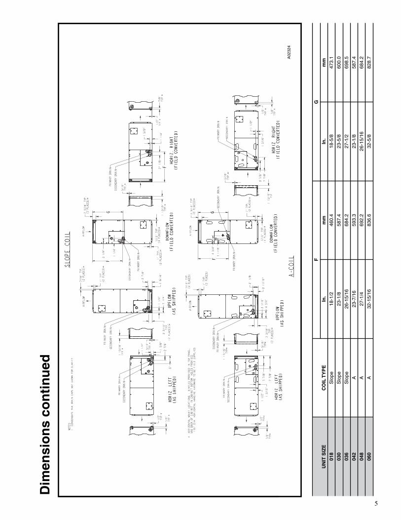
Dim
ensi
on
s co
nti
nu
ed
A02
324
UN
IT S
IZE
CO
IL T
YP
E
FG
In.
mm
In.
mm
018
Slo
pe18
-1/2
460.
418
-5/8
473.
1
030
Slo
pe23
-1/8
587.
423
-5/8
600.
0
036
Slo
pe26
-15/
1668
4.2
27-1
/269
8.5
042
A23
-7/1
659
3.3
23-1
/858
7.4
048
A27
-1/4
692.
226
-15/
1668
4.2
060
A32
-15/
1683
6.6
32-5
/882
8.7
6
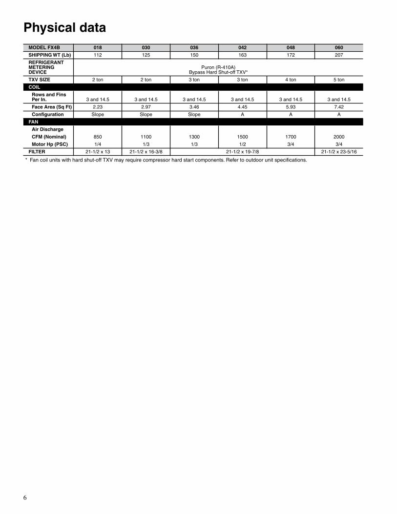
Physical data
* Fan coil units with hard shut-off TXV may require compressor hard start components. Refer to outdoor unit specifications.
MODEL FX4B 018 030 036 042 048 060
SHIPPING WT (Lb)
112 125 150 163 172 207
REFRIGERANT METERING DEVICE
Puron (R-410A)Bypass Hard Shut-off TXV*
TXV SIZE
2 ton 2 ton 3 ton 3 ton 4 ton 5 ton
COIL
Rows and Fins Per In.
3 and 14.5 3 and 14.5 3 and 14.5 3 and 14.5 3 and 14.5 3 and 14.5
Face Area (Sq Ft)
2.23 2.97 3.46 4.45 5.93 7.42
Configuration
Slope Slope Slope A A A
FAN
Air Discharge
CFM (Nominal)
850 1100 1300 1500 1700 2000
Motor Hp (PSC)
1/4 1/3 1/3 1/2 3/4 3/4
FILTER
21-1/2 x 13 21-1/2 x 16-3/8 21-1/2 x 19-7/8 21-1/2 x 23-5/16
7
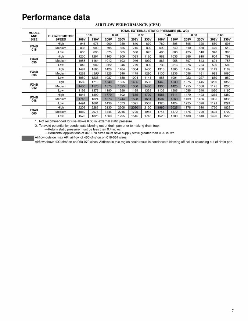
Performance data
AIRFLOW PERFORMANCE (CFM)
1. Not recommended for use above 0.60 in. external static pressure.2. To avoid potential for condensate blowing out of drain pan prior to making drain trap:
—Return static pressure must be less than 0.4 in. wc—Horizontal applications of 048-070 sizes must have supply static greater than 0.20 in. wc
Airflow outside max ARI airflow of 450 cfm/ton on 018-054 sizesAirflow above 400 cfm/ton on 060-070 sizes. Airflows in this region could result in condensate blowing off coil or splashing out of drain pan.
MODELANDSIZE
BLOWER MOTOR SPEED
TOTAL EXTERNAL STATIC PRESSURE (IN. WC)0.10 0.20 0.30 0.40 0.50 0.60
208V 230V 208V 230V 208V 230V 208V 230V 208V 230V 208V 230V
FX4B018
High 945 975 900 930 840 870 780 805 695 725 560 595Medium 835 900 795 855 745 800 690 740 610 650 470 510
Low 605 695 575 665 530 625 485 580 425 510 340 395
FX4B030
High 1230 1291 1163 1209 1083 1120 982 1036 886 918 804 799Medium 1055 1164 1012 1103 946 1039 863 958 797 843 691 757
Low 846 982 822 946 779 890 733 816 676 734 590 589
FX4B036
High 1497 1565 1428 1484 1364 1430 1313 1365 1234 1280 1149 1189Medium 1262
1390
1225 1340 1179 1280 1130 1236 1058 1161 993 1080Low 1080 1236 1037 1180 1004 1141 958 1091 923 1027 860 959
FX4B042
High 1580 1710 1540 1655 1495 1595 1440 1530 1375 1445 1290 1355Medium 1400 1570 1375 1525 1350 1480 1305 1425 1255 1360 1175 1280
Low 1195 1375 1180 1350 1165 1325 1135 1285 1085 1240 1020 1160
FX4B048
High 1846 1890 1779 1802 1685 1709 1586 1611 1479 1493 1365 1380Medium 1745 1824 1673 1744 1598 1661 1507 1560 1409 1466 1305 1335
Low 1494 1661 1438 1573 1395 1507 1320 1424 1225 1320 1121 1224
FX4B060
High 2205 2285 2130 2205 2050 2120 1960 2025 1875 1930 1790 1825Medium 1880 2075 1845 2015 1795 1945 1745 1870 1675 1790 1595 1700
Low 1570 1825 1560 1795 1545 1745 1520 1700 1480 1640 1420 1565

8
Performance data continued
MINIMUM CFM AND MOTOR SPEED SELECTION
*Indicates medium speed (blue). All other motor speeds at low tap.
FACTORY-INSTALLED FILTER STATIC PRESSURE DROP (IN. WC)
ELECTRIC HEATER STATIC PRESSURE DROP (IN. WC)
018, 030, 036
The airflow performance data was developed using fan coils with 10-kw electric heaters (2 elements) in the 018, 030, and 036 size units and 15-kw heaters (3 elements) in the 042 through 060 size units. For fan coils with heaters of a different number of elements, the external available static at a given CFM from the curve may be corrected by adding or subtracting available external static pressure as indicated above.
AIR DELIVERY PERFORMANCE CORRECTION COMPONENT PRESSURE DROP
(IN. WC)
AT INDICATED AIRFLOW (DRY-TO-WET COIL)
NOTE:
Subtract the above pressure drop corrections from unit airflow data when that component or condition is used. The remaining external static pressure will be available for the duct system.
FAN COIL SIZESFX
HEATER KW
3 5 8 9 10 15 18 20 24 30
018
700 700 700 — 700 775* — — — —
030
— 875 875 — 875 875 — 1060 — —
036
— 1050 970 970 970 920 — 1040 — —
042
— — 1225 1225 1225 1225 1225 1225 — —
048
— — 1400 1400 1400 1400 1400 1400 1400 1400
060
— — 1750 1750 1750 1750 1750 1750 1750 1750
UNITSIZE
CFM
600 800 1000 1200 1400 1600 1800 2000
018
0.044 0.750 0.110 — — — — —
030
— 0.048 0.072 0.100 — — — —
036
— — 0.072 0.100 0.130 — — —
042
— — — 0.070 0.092 0.120 — —
048
— — — — 0.092 0.120 0.152 —
060
— — — — — 0.086 0.105 0.130
HEATERELEMENTS KW
EXTERNAL STATIC PRESSURE
CORRECTION
0
0 +.02
1
3, 5 +.01
2
8, 10 0
3
9, 15 –.02
4
20 –.04
UNITSIZE
CFM
500 600 700 800 900 1000 1100 1200 1300 1350
018
0.035 0.051 0.066 0.080 0.091 — — — — —
030
— — — 0.051 0.063 0.073 0.081 — — —
036
— — — — — 0.073 0.081 0.091 0.098 0.102
UNITSIZE
CFM
1200 1300 1400 1500 1600 1700 1800 1900 2000
042
0.075 0.083 0.091 0.098 — — — — —
048
— — 0.066 0.073 0.080 0.086 0.091 — —
060
— — — — 0.030 0.034 0.039 0.044 0.053
042–060
HEATERELEMENTS KW
EXTERNAL STATIC PRESSURE
CORRECTION
0
0 +.04
2
8, 10 +.02
3
9, 15 0
4
20 –.02
6
18, 24, 30 –.10

9
Performance data continued
GROSS COOLING CAPACITIES (MBH)
See notes on pg. 10.
UNIT
EVAPORATOR AIR
CFM ANDBF
COIL REFRIGERANT TEMPERATURE (°F)*
35 40 45 50 55
Evaporator Air — Entering Wet-Bulb Temp (°F)
72 67 62 72 67 62 72 67 62 72 67 62 72 67 62
FX4B018
600 39 33 27 36 29 23 31 24 18 27 19 15 21 14 12
0.05 19 20 22 17 19 20 15 16 17 13 14 15 11 12 12
700 42 35 29 38 31 25 34 27 20 29 21 17 23 16 14
0.06 20 22 24 18 20 22 17 18 20 15 16 17 13 14 14
875 47 39 32 42 35 28 38 30 23 32 24 20 26 18 17
0.08 22 25 28 21 23 26 19 21 23 17 19 20 15 16 17
FX4B030
700 53 44 35 48 38 29 42 32 23 36 25 19 28 17 16
0.17 25 27 28 23 24 25 20 22 22 18 19 19 15 15 16
875 60 50 40 55 44 34 48 37 27 41 29 23 32 20 19
0.20 28 31 33 26 28 30 23 25 27 21 22 23 17 19 19
1050 66 55 44 60 49 38 53 41 31 45 33 27 36 23 22
0.23 31 35 38 29 32 35 26 29 31 23 26 27 20 22 22
1125 68 57 46 62 50 40 55 43 33 47 34 28 37 24 23
0.24 32 36 40 30 33 36 27 30 32 24 27 28 21 23 23
FX4B036
800 59 48 38 53 42 32 46 35 24 39 27 20 30 18 16
0.20 28 29 31 25 27 28 22 23 24 19 20 20 16 16 16
1000 68 56 45 61 49 37 54 41 29 45 32 25 35 22 20
0.22 32 34 37 29 31 33 26 28 28 23 24 25 19 20 20
1200 75 62 49 68 54 42 60 45 34 50 36 29 40 25 23
0.25 35 39 42 32 36 38 29 32 33 26 28 29 22 23 23
1400 80 67 54 73 59 46 64 49 38 54 39 32 43 28 27
0.27 38 43 47 35 39 43 32 36 37 28 32 32 24 26 27
FX4B042
1000 69 57 46 62 50 39 54 42 31 45 33 25 35 23 20
0.05 33 35 37 30 32 33 26 28 29 23 24 25 19 20 20
1200 77 63 51 69 55 44 61 47 35 51 37 29 39 26 24
0.07 36 39 42 33 36 38 29 32 34 26 28 29 22 23 24
1350 82 68 55 74 59 46 65 50 38 54 39 31 42 28 26
0.08 39 43 46 35 39 41 32 35 37 28 30 31 23 26 26
1530 87 72 59 79 64 50 69 53 41 58 42 34 46 30 28
0.09 41 46 50 38 42 45 34 38 40 30 33 34 26 28 28
FX4B048
1200 83 69 56 75 61 48 66 52 39 56 41 32 45 30 26
0.05 39 43 46 36 39 42 32 35 37 28 31 32 24 26 26
1400 90 75 61 82 66 53 72 57 43 61 45 36 49 33 30
0.06 42 47 51 39 43 47 35 39 42 31 34 36 27 29 30
1600 95 79 65 87 71 56 77 60 47 66 48 40 52 36 33
0.07 45 51 55 42 47 51 38 42 46 34 38 40 29 32 33
1750 99 83 68 90 74 59 80 63 50 69 51 42 55 37 35
0.08 47 53 59 44 49 54 40 45 49 36 40 42 31 34 35
FX4B060
1300 91 74 60 81 65 51 72 55 41 60 44 31 48 31 26
0.03 43 46 48 39 41 43 35 37 38 30 32 31 25 27 26
1600 104 85 69 94 76 59 83 64 47 70 51 38 55 37 31
0.05 49 53 57 45 49 51 40 44 45 35 38 38 30 32 31
1750 109 91 73 99 80 63 87 68 51 74 54 41 58 39 33
0.05 52 57 61 47 52 55 43 47 49 38 41 41 32 35 33
2000 117 97 80 106 86 68 94 74 56 80 59 45 64 43 38
0.06 56 62 67 51 57 61 46 51 54 41 45 45 35 39 38
10
* Saturated suction leaving evaporator coil.
Sensible Heat Capacity (1000 Btuh)Gross Cooling Capacity (1000 Btuh)
BF
— Bypass Factor
NOTES:
1. Contact manufacturer for cooling capacities at conditions other thanshown in table.
2. Formulas:Leaving db = entering db —
Leaving wb = wb corresponding to enthalpy of air leaving coil (h
lwb
)
h
lwb
= h
ewb
—
where h
ewb
= enthalpy of air entering coil.3. Direct interpolation is permissible. Do not extrapolate.
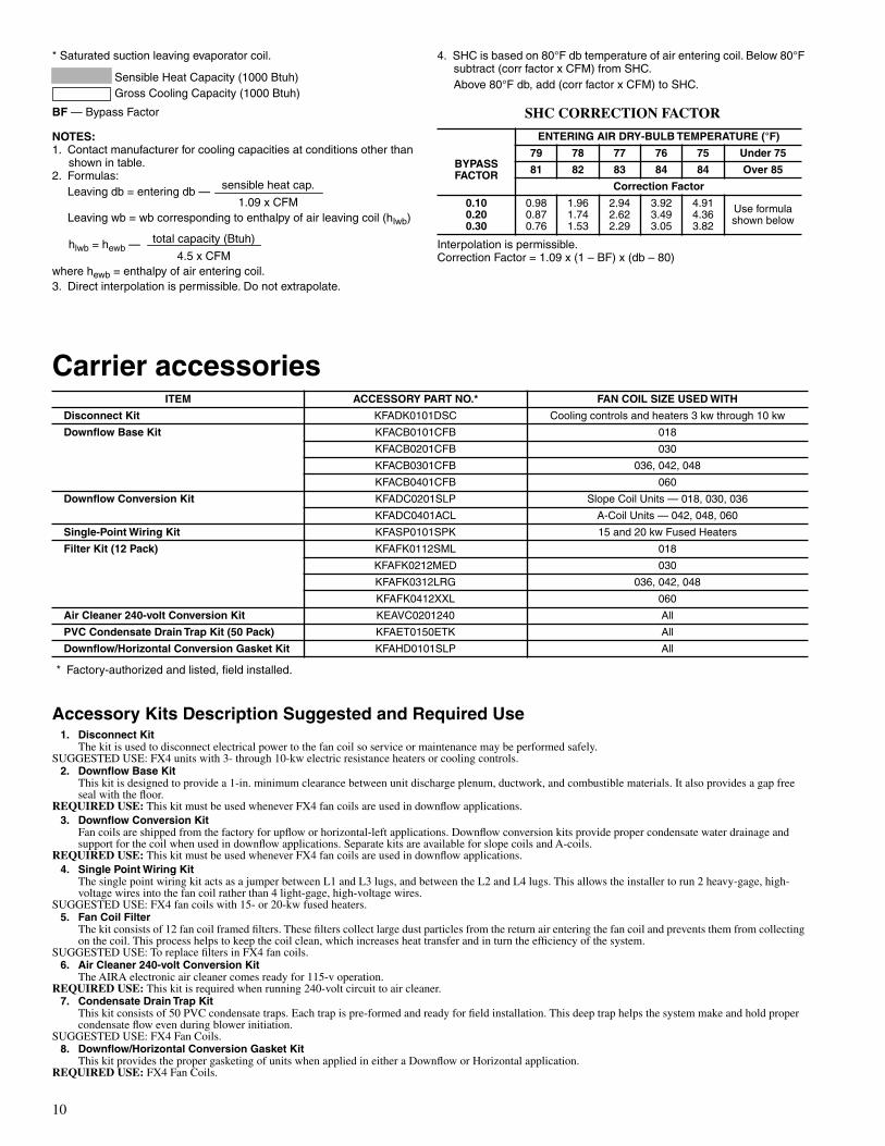
Carrier accessories
* Factory-authorized and listed, field installed.
Accessory Kits Description Suggested and Required Use
1. Disconnect Kit
The kit is used to disconnect electrical power to the fan coil so service or maintenance may be performed safely. SUGGESTED USE: FX4 units with 3- through 10-kw electric resistance heaters or cooling controls.
2. Downflow Base Kit
This kit is designed to provide a 1-in. minimum clearance between unit discharge plenum, ductwork, and combustible materials. It also provides a gap free seal with the floor.
REQUIRED USE:
This kit must be used whenever FX4 fan coils are used in downflow applications.
3. Downflow Conversion Kit
Fan coils are shipped from the factory for upflow or horizontal-left applications. Downflow conversion kits provide proper condensate water drainage and support for the coil when used in downflow applications. Separate kits are available for slope coils and A-coils.
REQUIRED USE:
This kit must be used whenever FX4 fan coils are used in downflow applications.
4. Single Point Wiring Kit
The single point wiring kit acts as a jumper between L1 and L3 lugs, and between the L2 and L4 lugs. This allows the installer to run 2 heavy-gage, high-voltage wires into the fan coil rather than 4 light-gage, high-voltage wires.
SUGGESTED USE: FX4 fan coils with 15- or 20-kw fused heaters.
5. Fan Coil Filter
The kit consists of 12 fan coil framed filters. These filters collect large dust particles from the return air entering the fan coil and prevents them from collecting on the coil. This process helps to keep the coil clean, which increases heat transfer and in turn the efficiency of the system.
SUGGESTED USE: To replace filters in FX4 fan coils.
6. Air Cleaner 240-volt Conversion Kit
The AIRA electronic air cleaner comes ready for 115-v operation.
REQUIRED USE:
This kit is required when running 240-volt circuit to air cleaner.
7. Condensate Drain Trap Kit
This kit consists of 50 PVC condensate traps. Each trap is pre-formed and ready for field installation. This deep trap helps the system make and hold proper condensate flow even during blower initiation.
SUGGESTED USE: FX4 Fan Coils.
8. Downflow/Horizontal Conversion Gasket Kit
This kit provides the proper gasketing of units when applied in either a Downflow or Horizontal application.
REQUIRED USE:
FX4 Fan Coils.
ITEM ACCESSORY PART NO.* FAN COIL SIZE USED WITH
Disconnect Kit
KFADK0101DSC Cooling controls and heaters 3 kw through 10 kw
Downflow Base Kit
KFACB0101CFB 018
KFACB0201CFB 030
KFACB0301CFB 036, 042, 048
KFACB0401CFB 060
Downflow Conversion Kit
KFADC0201SLP Slope Coil Units — 018, 030, 036
KFADC0401ACL A-Coil Units — 042, 048, 060
Single-Point Wiring Kit KFASP0101SPK 15 and 20 kw Fused Heaters
Filter Kit (12 Pack) KFAFK0112SML 018
KFAFK0212MED 030
KFAFK0312LRG 036, 042, 048
KFAFK0412XXL 060
Air Cleaner 240-volt Conversion Kit KEAVC0201240 All
PVC Condensate Drain Trap Kit (50 Pack) KFAET0150ETK All
Downflow/Horizontal Conversion Gasket Kit KFAHD0101SLP All
sensible heat cap.
1.09 x CFM
total capacity (Btuh)
4.5 x CFM
4. SHC is based on 80°F db temperature of air entering coil. Below 80°F subtract (corr factor x CFM) from SHC.Above 80°F db, add (corr factor x CFM) to SHC.
SHC CORRECTION FACTOR
Interpolation is permissible.Correction Factor = 1.09 x (1 – BF) x (db – 80)
ENTERING AIR DRY-BULB TEMPERATURE (°F)
BYPASS FACTOR
79 78 77 76 75 Under 75
81 82 83 84 84 Over 85
Correction Factor
0.100.200.30
0.980.870.76
1.961.741.53
2.942.622.29
3.923.493.05
4.914.363.82
Use formula shown below
11
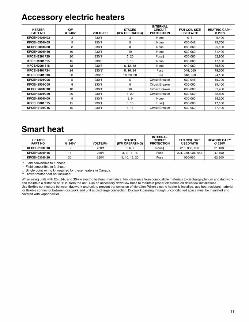
Accessory electric heaters
Smart heat
* Field convertible to 1 phase.† Field convertible to 3 phase.‡ Single point wiring kit required for these heaters in Canada.** Blower motor heat not included.
When using units with 20-, 24-, and 30-kw electric heaters, maintain a 1-in. clearance from combustible materials to discharge plenum and ductwork and maintain a distance of 36 in. from the unit. Use an accessory downflow base to maintain proper clearance on downflow installations.Use flexible connectors between ductwork and unit to prevent transmission of vibration. When electric heater is installed, use heat resistant material for flexible connector between ductwork and unit at discharge connection. Ductwork passing through unconditioned space must be insulated and covered with vapor barrier.
HEATERPART NO.
KW @ 240V VOLTS/PH
STAGES(KW OPERATING)
INTERNALCIRCUIT
PROTECTIONFAN COIL SIZE
USED WITHHEATING CAP.**
@ 230V
KFCEH0401N03 3 230/1 3 None 018 9,400
KFCEH0501N05 5 230/1 5 None 030-048 15,700
KFCEH0801N08 8 230/1 8 None 030-060 25,100
KFCEH0901N10 10 230/1 10 None 030-060 31,400
KFCEH3201F20 20 230/1 5, 20 Fuse‡ 030-060 62,800
KFCEH1601315 15 230/3 5, 15 None 036-060 47,100
KFCEH2001318 18 230/3 6, 12, 18 None 042-060 56,500
KFCEH3401F24 24 230/3* 8, 16, 24 Fuse 048, 060 78,300
KFCEH3501F30 30 230/3* 10, 20, 30 Fuse 048, 060 94,100
KFCEH2401C05 5 230/1 5 Circuit Breaker 030-048 15,700
KFCEH2501C08 8 230/1 8 Circuit Breaker 030-060 25,100
KFCEH2601C10 10 230/1 10 Circuit Breaker 030-060 31,400
KFCEH3301C20 20 230/1 5, 20 Circuit Breaker 030-060 62,800
KFCEH2901N09 9 230/1† 3, 9 None 030-060 28,200
KFCEH3001F15 15 230/1 5, 15 Fuse‡ 030-060 47,100
KFCEH3101C15 15 230/1 5, 15 Circuit Breaker 030-060 47,100
HEATERPART NO.
KW @ 240V VOLTS/PH
STAGES(KW OPERATING)
INTERNALCIRCUIT
PROTECTIONFAN COIL SIZE
USED WITHHEATING CAP.**
@ 230V
KFCEH0101H10 9 230/1 3, 6, 9 None‡ 018, 030, 036 31,400
KFCEH0201H15 15 230/1 3, 8, 11, 15 Fuse 024, 030, 036, 048 47,100
KFCEH0301H20 20 230/1 5, 10, 15, 20 Fuse 030-060 62,800
12
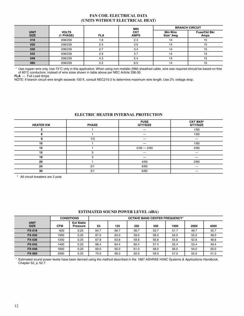
FAN COIL ELECTRICAL DATA(UNITS WITHOUT ELECTRICAL HEAT)
* Use copper wire only. Use 75°C only in this application. When using non-metallic (NM) sheathed cable, wire size required should be based on that of 60°C conductors, instead of wire sizes shown in table above per NEC Article 336-30.
FLA — Full Load AmpsNOTE: If branch circuit wire length exceeds 100 ft, consult NEC215-2 to determine maximum wire length. Use 2% voltage drop.
ELECTRIC HEATER INTERNAL PROTECTION
* All circuit breakers are 2 pole.
ESTIMATED SOUND POWER LEVEL (dBA)
* Estimated sound power levels have been derived using the method described in the 1987 ASHRAE HVAC Systems & Applications Handbook, Chapter 52, p. 52.7.
UNITSIZE
VOLTS(1 PHASE) FLA
MINCKT
AMPS
BRANCH CIRCUIT
Min WireSize* Awg
Fuse/Ckt BkrAmps
018 208/230 1.8 2.3 14 15
030 208/230 2.4 3.0 14 15
036 208/230 2.7 3.4 14 15
042 208/230 2.9 3.7 14 15
048 208/230 4.3 5.4 14 15
060 208/230 5.2 6.5 14 15
HEATER KW PHASEFUSE
QTY/SIZECKT BKR*QTY/SIZE
5 1 — 1/60
8 1 — 1/60
9 1/3 — —
10 1 — 1/60
15 1 2/30 — 2/60 2/60
15 3 — —
18 3 — —
20 1 4/60 2/60
24 3/1 6/60 —
30 3/1 6/60 —
UNITSIZE
CONDITIONS OCTAVE BAND CENTER FREQUENCY*
CFMExt Static Pressure 63 125 250 500 1000 2000 4000
FX-018 600 0.25 64.7 60.7 56.7 53.7 51.7 49.7 45.7
FX-030 1000 0.25 67.0 63.0 59.0 56.0 54.0 52.0 48.0
FX-036 1200 0.25 67.8 63.8 59.8 56.8 54.8 52.8 48.8
FX-042 1400 0.25 68.4 64.4 60.4 57.4 55.4 53.4 49.4
FX-048 1600 0.25 69.0 65.0 61.0 58.0 56.0 54.0 50.0
FX-060 2000 0.25 70.0 66.0 62.0 59.0 57.0 55.0 51.0

13
Ele
ctri
c h
eate
r el
ectr
ical
dat
a SMA
RT
HE
AT
EL
EC
TR
ICA
L D
AT
A
FIE
LD
MU
LT
IPO
INT
WIR
ING
OF
24-
AN
D 3
0-K
W S
ING
LE
PH
ASE
†F
ield
con
vert
ible
to 1
pha
se, s
ingl
e or
mul
tiple
sup
ply
circ
uit.
‡F
ield
con
vert
ible
to 3
pha
se.
**In
clud
es b
low
er m
otor
am
ps o
f lar
gest
fan
coil
used
with
hea
ter.
††C
oppe
r w
ire m
ust b
e us
ed.
If ot
her
than
unc
oate
d (n
on-p
late
d), 7
5°C
am
bien
t, co
pper
wire
(so
lid w
ire fo
r 10
AW
G a
nd s
mal
ler,
stra
nded
wire
for
larg
er th
an 1
0 A
WG
) is
use
d, c
onsu
lt ap
plic
able
tabl
es o
f the
Nat
iona
l Ele
ctric
Cod
e
(AN
SI/N
FPA
70)
.‡‡
Leng
th s
how
n is
as
mea
sure
d 1
way
alo
ng w
ire p
ath
betw
een
unit
and
serv
ice
pane
l for
a v
olta
ge d
rop
not t
o ex
ceed
2%
.**
*H
eate
rs a
re In
telli
gent
Hea
t cap
able
whe
n us
ed w
ith th
e F
K, F
V fa
n co
ils a
nd c
orpo
rate
2-s
peed
pro
gram
mab
le th
erm
osta
t (T
STA
TC
CP
2S01
-B),
The
rmid
ista
t™ C
ontr
ol (
TS
TAT
CC
PR
H01
-B),
or
Com
fort
Zon
e II.
NO
TE
S:
1.F
or fa
n co
il si
zes
018,
030
, and
036
.2.
For
fan
coil
size
s 04
2-06
0 an
d al
l FK
4D, F
V4B
siz
es.
3.S
ingl
e ci
rcui
t app
licat
ion
of F
15 a
nd F
20 h
eate
rs r
equi
res
sing
le-p
oint
wiri
ng k
it ac
cess
ory
HE
AT
ER
PAR
T N
O.
KW
PH
AS
EIN
TE
RN
AL
CIR
CU
ITP
RO
TE
CT
ION
HE
AT
ER
AM
PS
208/
230V
BR
AN
CH
CIR
CU
IT
Min
Am
pac
ity
208/
230V
**M
in W
ire
Siz
e (A
WG
) 20
8/23
0V††
Min
Gn
d W
ire
Siz
e20
8/23
0VM
ax F
use
/Ckt
Bkr
Am
ps
208/
230V
Max
Wir
e L
eng
th20
8/23
0V (
Ft)
‡‡
Sin
gle
Cir
cuit
Du
al C
ircu
itS
ing
leC
ircu
it
Du
al C
ircu
itS
ing
leC
ircu
it
Du
al C
ircu
itS
ing
leC
ircu
it
Du
al C
ircu
itS
ing
leC
ircu
it
Du
al C
ircu
itS
ing
leC
ircu
it
Du
al C
ircu
it
240v
208v
L1,
L2
L3,
L4
L1,
L2
L3,
L4
L1,
L2
L3,
L4
L1,
L2
L3,
L4
L1,
L2
L3,
L4
L1,
L2
L3,
L4
KF
CE
H04
01N
033
2.3
1N
one
10.9
/12.
0—
—15
.9/1
7.3
——
12/1
2—
—12
/12
——
20/2
0—
—67
/68
——
KF
CE
H05
01N
051
53.
81
Non
e18
.1/2
0.0
——
26.0
/28.
4—
—10
/10
——
10/1
0—
—30
/30
——
66/6
6—
—
KF
CE
H05
01N
052
53.
81
Non
e18
.1/2
0.0
——
31.2
/33.
5—
—8/
8—
—10
/10
——
35/3
5—
—85
/88
——
KF
CE
H24
01C
051
53.
81
Ckt
Bkr
18.1
/20.
0—
—26
.0/2
8.4
——
10/1
0—
—10
/10
——
30/3
0—
—66
/66
——
KF
CE
H24
01C
052
53.
81
Ckt
Bkr
18.1
/20.
0—
—31
.2/3
3.5
——
8/8
——
10/1
0—
—35
/35
——
85/8
8—
—
KF
CE
H08
01N
088
6.0
1N
one
28.9
/32.
0—
—44
.7/4
8.5
——
8/8
——
10/1
0—
—45
/50
——
59/6
0—
—
KF
CE
H25
01C
088
6.0
1C
kt B
kr28
.9/3
2.0
——
44.7
/48.
5—
—8/
8—
—10
/10
——
45/5
0—
—59
/60
——
KF
CE
H29
01N
09**
*‡9
6.8
1N
one
32.8
/36.
0—
—49
.5/5
3.5
——
8/6
——
10/1
0—
—50
/60
——
54/8
7—
—
96.
83
Non
e18
.8/2
0.8
——
32.0
/34.
5—
—8/
8—
—10
/10
——
35/3
5—
—83
/85
——
KF
CE
H09
01N
1010
7.5
1N
one
36.2
/40.
0—
—53
.8/5
8.5
——
6/6
——
10/1
0—
—60
/60
——
78/8
0—
—
KF
CE
H26
01C
1010
7.5
1C
kt B
kr36
.2/4
0.0
——
53.8
/58.
5—
—6/
6—
—10
/10
——
60/6
0—
—78
/80
——
KF
CE
H30
01F
15**
*15
11.3
1F
use
54.2
/59.
936
.2/4
0.0
18.1
/20.
076
.3/8
3.4
53.8
/58.
522
.7/2
5.0
4/4
6/6
10/1
08/
810
/10
10/1
080
/90
60/6
025
/25
88/8
978
/80
75/7
6
KF
CE
H31
01C
15**
*15
11.3
1C
kt B
kr—
36.2
/40.
018
.1/2
0.0
—53
.8/5
8.5
22.7
/25.
0—
6/6
10/1
0—
10/1
010
/10
—60
/60
25/2
5—
78/8
075
/76
KF
CE
H16
0131
515
11.3
3N
one
31.3
/34.
6—
—47
.7/5
1.8
——
8/6
——
10/1
0—
—50
/60
——
56/9
0—
—
KF
CE
H20
0131
818
13.5
3N
one
37.6
/41.
5—
—55
.5/6
0.4
——
6/6
——
10/8
——
60/7
0—
—76
/77
——
KF
CE
H32
01F
20**
*20
15.0
1F
use
72.3
/79.
936
.2/4
0.0
36.2
/40.
098
.9/1
08.4
53.8
/58.
545
.3/5
0.0
3/2
6/6
8/8
8/6
10/1
010
/10
100/
110
60/6
050
/50
85/1
0978
/80
59/5
9
KF
CE
H33
01C
20**
*20
15.0
1C
kt B
kr—
36.2
/40.
036
.2/4
0.0
—53
.8/5
8.5
45.3
/50.
0—
6/6
8/8
—10
/10
10/1
0—
60/6
050
/50
—78
/80
59/5
9
KF
CE
H34
01F
24†*
**24
18.0
3F
use
50.1
/55.
4—
—71
.2/7
7.8
——
4/4
——
8/8
——
80/8
0—
—94
/95
——
2418
.01
Fus
e86
.7/9
5.5
——
116.
9/12
7.9
——
1/1
——
6/6
——
125/
150
——
115/
116
——
KF
CE
H35
01F
30†*
**30
22.5
3F
use
62.6
/69.
2—
—86
.8/9
5.0
——
3/3
——
8/8
——
90/1
00—
—97
/98
——
3022
.51
Fus
e10
9.0/
120.
0—
—14
4.8/
158.
5—
—0/
00—
—6/
6—
—15
0/17
5—
—11
7/15
0—
—
HE
AT
ER
PAR
T N
O.
KW
PH
AS
EIN
TE
RN
AL
CIR
CU
ITP
RO
TE
CT
ION
HE
AT
ER
AM
PS
208/
230V
BR
AN
CH
CIR
CU
IT
Min
Am
pac
ity
208/
230V
**M
in W
ire
Siz
e (A
WG
) 20
8/23
0V††
Min
Gn
d W
ire
Siz
e20
8/23
0VM
ax F
use
/Ckt
Brk
Am
ps
208/
230V
Max
Wir
e L
eng
th20
8/23
0V (
Ft)
‡‡
Sin
gle
Cir
cuit
Du
al C
ircu
itS
ing
leC
ircu
it
Du
al C
ircu
itS
ing
leC
ircu
it
Du
al C
ircu
itS
ing
leC
ircu
it
Du
al C
ircu
itS
ing
leC
ircu
it
Du
al C
ircu
itS
ing
leC
ircu
it
Du
al C
ircu
it
240v
208v
L1,
L2
L3,
L4
L1,
L2
L3,
L4
L1,
L2
L3,
L4
L1,
L2
L3,
L4
L1,
L2
L3,
L4
L1,
L2
L3,
L4
KF
CE
H01
01H
1010
7.5
1N
one
32.5
/35.
9—
—44
.0/4
8.3
——
8/8
——
10/1
0—
—45
/50
——
60/6
1—
—
KF
CE
H02
01H
1515
11.3
1F
use
54.2
/59.
939
.7/4
3.9
14.4
/16.
073
.2/8
0.3
49.7
/54.
923
.4/2
5.4
4/4
8/6
10/1
08/
810
/10
10/1
080
/90
50/6
025
/30
92/9
253
/85
73/7
4
KF
CE
H03
01H
2020
15.0
1F
use
72.3
/79.
936
.2/4
0.0
36.2
/40.
097
.2/1
06.7
52.0
/56.
845
.3/5
0.0
3/2
6/6
8/8
8/6
10/1
010
/10
100/
110
60/6
050
/50
87/1
1181
/82
93/9
3
HE
AT
ER
PA
RT
NO
.K
WP
HA
SE
HE
AT
ER
AM
PS
208/
230V
MIN
AM
PA
CIT
Y20
8/23
0V**
MIN
WIR
E S
IZE
(A
WG
)20
8/23
0V††
MIN
GN
D
WIR
E S
IZE
208/
230V
MA
X F
US
E/C
KT
BK
R A
MP
S20
8/23
0VM
AX
WIR
E L
EN
GT
H20
8/23
0V (
FT
)‡‡
240V
208V
L1,
L2
L3,
L4
L5,
L6
L1,
L2
L3,
L4
L5,
L6
L1,
L2
L3,
L4
L5,
L6
L1,
L2
L3,
L4
L5,
L6
L1,
L2
L3,
L4
L5,
L6
KF
CE
H34
01F
24†*
**24
18.0
1 28
.9/3
2.0
28.9
/32.
028
.9/3
2.0
44.7
/48.
536
.2/4
0.0
36.2
/40.
08/
88/
88/
810
/10
45/5
040
/40
40/4
059
/60
73/7
373
/73
KF
CE
H35
01F
30†*
**30
22.5
1 36
.2/4
0.0
36.2
/40.
036
.2/4
0.0
53.8
/58.
545
.3/5
0.0
45.3
/50.
06/
68/
88/
810
/10
60/6
050
/50
50/5
078
/80
59/5
959
/59

14
Matched system
A02331
ELECTRONICAIR CLEANER
COMFORT VENTILATOR
COMFORT ZONE IIEQUIPMENT CONTROLLER
™
HEAT PUMP
HUMIDIFIER FAN COIL

15
Copyright 2003 Carrier Corporation • Indianapolis, IN 46231 9-03
Manufacturer reserves the right to discontinue, or change at any time, specifications or designs without notice and without incurring obligations.
Book 1 4 Page 16 Catalog No. 02FX-4B2 Printed in U.S.A. PC 101 Form FX4B-3PD
Tab 3d 2e Replaces: FX4B-2PD