Embed Size (px)
Citation preview

TECHNOLOGY DEMONSTRATION TEST PLAN
PROJECT 4 TASK 2: D&D SUPPORT FOR TECHNOLOGY INNOVATION, DEVELOPMENT,
EVALUATION AND DEPLOYMENT
FX2 Advanced Fogging Technology
January 16, 2015
Submitted by:
Leonel Lagos Ph.D., PMP® Applied Research Center
Florida International University 10555 W. Flagler Street, EC2100
Miami, FL 33174
Prepared for:
U.S. Department of Energy Office of Environmental Management
Cooperative Agreement No. DE-EM0000598
FIU-ARC-2014-800000440-02c-225 FX2 Advanced Fogging Test Plan
TABLE OF CONTENTS
1.0 INTRODUCTION AND PROBLEM STATEMENT .................................................. 1
2.0 TECHNOLOGY DESCRIPTION ................................................................................ 3
3.0 TEST OBJECTIVES AND METHODOLOGY ........................................................... 5
4.0 PERFORMANCE MEASUREMENT AND DATA COLLECTION ........................ 14
5.0 ROLES AND RESPONSIBILITIES .......................................................................... 15
6.0 DEMONSTRATION SCHEDULE ............................................................................ 17
7.0 DOCUMENTATION ................................................................................................. 19
8.0 HEALTH AND SAFETY ........................................................................................... 20
9.0 WASTE DISPOSITION ............................................................................................. 21
10.0 REFERENCES ......................................................................................................... 22

FIU-ARC-2014-800000440-02c-225 FX2 Advanced Fogging Test Plan
1
1.0 INTRODUCTION AND PROBLEM STATEMENT
In discussions with representatives from the Savannah River National Lab (SRNL), the
requirement for an advanced fogging technology that could better address potential
airborne contaminants than existing products and technologies was identified. The
deactivation and decommissioning challenges being faced by the SRS 235-F Project have
precipitated a requirement for more advanced fogging technologies in the areas of capture
coating fogging agents themselves, as well as the delivery mechanisms for their
dispersion. In several of the older processing facilities, it is well known that
contamination, in some cases substantial contamination, is evident throughout the exhaust
ductwork due to the years of processing in glove boxes, etc. Large accumulations of
radioactive dust and lint are present that have the potential to become airborne from
disposal site exhumation, laundry facilities, exhaust ventilation ducting and exhaust
stacks, all of which pose significant risk and critical concern.
There have been previous attempts at applying a coating to capture the high levels of
airborne contamination with varying degrees of success in various facilities across the
DOE enterprise. On occasion, these attempts have not been successful in penetrating and
causing adherence of contaminated lint and dust to the ductwork and other surfaces. As a
result, the contamination was not fixed and ultimately became airborne when it was
disturbed. Also, traditional methods of capturing this contamination have been very labor
intensive by placing a worker in the area to spray a coating and exposing personnel to the
hazard. Likewise, spraying a coating in an area with penetrations, such as auxiliary piping
and other equipment, usually does not fix contamination that is “shadowed” by such
items. Further complicating the issue, some coatings, such as glycerin, leave a residue
that is slippery and could cause a secondary potential hazard, while using excessive
amounts of water to control dust presents a radiological waste issue. Thus, an improved
capture coating and delivery mechanism was identified as a need to resolve these
contamination issues. (1)
In response, FIU has focused its efforts on identifying, testing, evaluating, and enhancing
innovative fogging technologies in support of the SRS 235-F project. The SRS 235-F
facility was constructed in the 1950’s as part of the weapons complex materials
production and fabrication. The building is approximately 24,000 ft2 per floor totaling
48,000 ft2. The blast resistant, two-level, windowless structure was built to meet NPH
PC-3 seismic and wind design criteria. The facility was built on a reinforced concrete
slab foundation with 14-inch thick exterior walls constructed of double-reinforced
concrete. The 235-F building has three separate ancillary facilities: 291-2F (stack), 292-
2F (sand filter fan house), and 294-2F (sand filter) plus an underground concrete tunnel
connecting 235-F to the sand filter. Major modifications to the facility began in the mid-

FIU-ARC-2014-800000440-02c-225 FX2 Advanced Fogging Test Plan
2
1970s to support the new Pu-238 fuel mission for NASA. The most significant quantities
of residual contamination remaining in 235-F building are found in the Plutonium Fuel
Form (PuFF), Plutonium Experimental Facility (PEF), Old Metallography Lab (OML),
and Actinide Billet Line (ABL) facilities.
A research initiative started and further developed at Idaho National Laboratory (INL) on
a new contamination capture coating and fogging agent, currently dubbed FX2, has been
highlighted as having tremendous potential in addressing the airborne contaminant
problem at SRS 235-F and throughout the DOE enterprise. This fogging fixative contains
a sticky base and surfactant that behaves similar to a gas upon dispersion and can be
introduced into targeted spaces at low pressure and low velocity to increase its
penetration into hard-to-reach areas. It then captures and fixes radioactive materials,
metals and other contamination in place. Furthermore, recent tests conducted at INL
demonstrated that the FX2 agent could be adequately dispersed via commercial-off-the-
shelf (COTS) fogging delivery systems, thereby potentially diminishing the requirement
for specially designed equipment that in turn reduces costs. The technology improves
safety during nuclear facility decommissioning by assuring that contamination does not
spread or expose workers during decontamination operations. Through extensive
coordination via phone, email, and site visits, FIU is overseeing a collaborative testing
and evaluation effort with SRNL and INL to advance the development, and eventual field
deployment, of the FX2 Advanced Fogging Technology in a radioactive contaminated
environment. It is an integrated approach designed to reduce technical risks, improve
safety, and limit uncertainty within D&D operations.
The majority of the FX2 technology demonstration will occur at the FIU Testing
Facilities in Miami, Florida, starting on or about 30 Mar – 3 Apr 2015, or until the test
objectives outlined in this document have been satisfactorily achieved. The purpose and
intent of this FIU technology evaluation is to subject the FX2 fogging agent to the next
phase of testing, consistent with ASTM universally accepted standards where applicable,
in order to more completely characterize the agent in the areas of flash / ignition point,
burn rate, and ability to provide for the control of airborne particulate contamination to
levels appropriate for accomplishing contamination-sensitive activities. If the necessary
site-specific geometry data is provided with sufficient lead time and deemed feasible,
FIU will conduct the tests in a mockup that duplicates the desired SRNL dimensions and
geometries where the agent is most likely to be deployed in a hot technology
demonstration to address real-world, radioactive decontamination scenarios. All findings
from the demonstration will be published as an ARC technical report and a technology
fact sheet will also be developed. FIU will provide these reports to DOE EM as a project
deliverable and for further dissemination.
FIU-ARC-2014-800000440-02c-225 FX2 Advanced Fogging Test Plan
3
2.0 TECHNOLOGY DESCRIPTION
Potential fogging technologies were researched via: (1) FIU D&D technology databases
(D&D KM-IT), (2) Internet search, (3) subject matter experts, and (4) professional
conferences and forums. Based on that research, the FX2 Advanced Fogging agent and
COTS delivery system employed by INL appeared to be a very viable, cost effective
method to mitigate airborne contamination hazards that would potentially be encountered
at the SRS 235-F Project. Additionally, it provides a unique opportunity to demonstrate
and further the development of an effort that has shown some strong, initial promise. The
description of the technologies outlined below is extracted from an INL Advanced
Fogging Technologies report drafted in 2014.
Fogging Agent: The FX2 fogging agent is a proprietary mixture of water, latex paint
(LTX), glycerin (GLY) and sodium lauryl sulfate (SLS) optimized to penetrate dusty
contaminants and bind them into a film. Initial development of an acceptable fogging
agent began in 2006, when a DOE Small Business Innovative Research (SBIR) grant
resulted in the development of a conceptual advanced capture coating fog system. This
coating was shown to be superior at reducing airborne contamination and “fixing” it in
place compared to the few other commercial fogging agents.
During FY-2014, the INL built upon those initial findings and further refined the fogging
agent mixture, resulting in a solution that optimized effectiveness in addressing potential
airborne contaminants and produced superior results to the 2006 effort. The initial
objective of the solution development was to achieve a fogged capture coating which
would allow for easy application, unmanned operation and flow through facilities and
equipment. The solution had to “knock down” and fix existing airborne particulates, as
well as penetrate through the surface layer of dust and “freeze” the dusty contaminants,
fixing them to the substrate. This new coating demonstrated better penetration of the lint
and dust, and an ability to stabilize potentially respiratory particles. All of the additives
are common materials, found in paint and shampoo for example, and none are considered
harmful (beyond being irritants in higher concentrations). The solutions are aqueous and
generally clean up with soap and water. Based on the laboratory tests that compared
wetness, stickiness, dustiness and penetration, several coatings showed improved
performance over the conventional glycerin fogging technique.
Stationary Fogging Delivery System: The set of experiments conducted by the INL
also validated the approach of using an inexpensive, unsophisticated fogger and a
portable blower to control the buildup of fog. Previously it was thought that testing the
FX2 Fogging Agent would require more sophisticated equipment. However, a fogger that
produced the proper droplet size was commercially available at an inexpensive price.

FIU-ARC-2014-800000440-02c-225 FX2 Advanced Fogging Test Plan
4
Though different configurations and techniques of employment will be tested, FIU will
employ the Cyclone Fogger by Curtis Dyna-Fog (see Figure 1). The fogger contains an
ultra-low volume (ULV) nozzle that can subject the FX2 Fogging Agent to fewer than 20
microns and produces a flow rate of .07 liters per minute. The capacity of the tank is one
gallon (3.8 liters). The Cyclone Ultra-Flex weighs approximately 10 lbs. and
approximately 16 lbs. with a full tank.
Input Power: 110/120 V AC, 8.5 amps, 50/60 Hz
(models 3000, 3000-1),
210/250 V AC, 4.2 amps, 50/60 Hz
(models 3004, 3004-1).
Adjustable flow rate: 0-5 gal/h. (0-19 L/h.)
Particle Size: 5-30 microns.
Tank capacity: 1 gal. (3.8 L).
Length: 54 in. (137 cm).
Width: 8 in. (20.2 cm).
Height: 14.5 in. (36.5cm).
Weight empty: 10.5 lbs. (4.8 kg.)
Shipping data: L x W x H: 27 in. x 12 in. x 17 in.
(68cm x 30 cm x 43 cm)
Weight: 16 lbs. (7.26 kg.),
Volume: 3.2 cubic feet.
(0.09 cubic meter).
Option: 36 inch (91 cm) flex hose.
Figure 1. Cyclone Fogger by Curtis Dyna-Fog

FIU-ARC-2014-800000440-02c-225 FX2 Advanced Fogging Test Plan
5
3.0 TEST OBJECTIVES AND METHODOLOGY
There are four (4) primary test objectives associated with this Test Plan: 1) Test and
evaluate the FX2 fogging agent’s capacity to “knock down” and fix airborne particulates,
as well as coat and fix loose surrogate contamination with the potential to go airborne,
both within and outside the direct line-of-sight of the dispersion nozzle and using various
surface types (eg: metal, plastic, wood, etc) in differing geometries; 2) Determine the
ignitability of the FX2 Fogging Agent during stationary application; 3) Determine the
shielding abilities of the FX2 Fogging Agent against an alpha emitter source; and 4)
Determine the ignition / flash point and burn rate characteristics of the FX2 Fogging
Agent.
3.1: Evaluate FX2 Fogging Agent in Controlling (ie: Knocking Down and Fixing)
Potential Airborne Particulates, Both Line of Sight and Non-Line of Sight, on
Various Surfaces in Varied Geometries
1) This represents the primary objective for the Test Plan, and is intended to: 1) Confirm
previous findings related to FX2’s capacity to satisfactorily fix contaminants on
various surfaces in varying geometries; 2) Evaluate FX2’s capacity to knock down
and fix suspended airborne particulates in varying geometries; and 3) Evaluate FX2’s
overall fogging ability to satisfactorily coat both line of sight and non-line of sight
contaminants in varying geometries. FIU will utilize their hot cell mockup facility
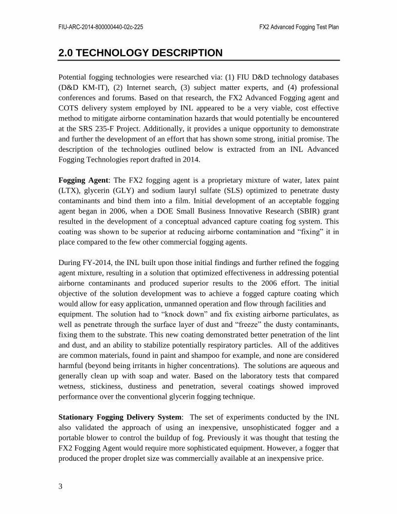
and create three (3) separate dimensions / geometries as outlined in the below figures.
These dimensions / geometries will be created in sequential order, starting with the
smallest configuration (Figure 2) and progressing to the larger ones (Figures 3-4).
Dividers constructed from plywood and/or fire retardant canvas will be used to create
the desired dimensions, with careful attention paid to making the best use of the
existing structure (ie: window, entry portholes, etc). This will ensure optimization of
the existing structure and facilitate attaching the fogger and ventilation systems for
remote application of the FX2 agent, while also allowing for easier visibility during
the conduct of the respective tests. Appropriate measures will be taken to ensure the
designs are adequately sealed for maximum effectiveness of the experiments. INL
tested the FX2 agent using the Dyna Fogger depicted above in a small make shift tent
that was approximately 2.5m x 2.5m x 2m (~8’x8’x6’) with adequate results, and
assessed that the Dyna Fogger delivery system may be able to uniformly disperse the
FX2 agent in a room as large as 6m x 6m x 3m (~18’x18’x10’). The dimensions to be
tested by FIU are all larger than the test dimensions used by INL during their
experiment, but generally fall within the range of the assessed effective area size. The
three scenarios that FIU will implement (FIU mockup) are as follow:
Scenario 1 is 10’x10’x10’(show in Figure 2)

FIU-ARC-2014-800000440-02c-225 FX2 Advanced Fogging Test Plan
6
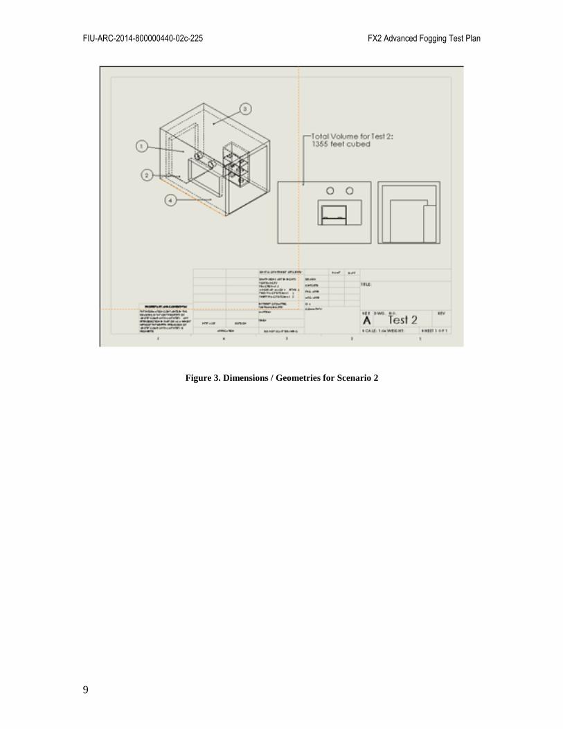
Scenario 2 is 10’x15’x10’ (shown in Figure 3)
Scenario 3 is 10’x20’x10’ (shown in Figure 4)
**NOTE: As previously stated, if provided by SRNL on or about 16 January 2015,
FIU could replicate the desired dimensions and geometries associated with any
potentially planned “hot demo” of the FX2 fogging agent in a radioactive
environment. This will allow for a rehearsal of the hot demo in a cold environment
before the actual event.
2) Petri dishes and coupons will be placed in the designated locations as outlined in the
below figures for each of the three dimensions / geometries tested. The petri dishes
will contain talcum powder / lint to simulate contaminants with the potential to
become airborne, and the coupons will consist of polypropylene cloth/batting
coupons cut into 10 cm squares. Additionally, a 3-shelved utility shelf will be placed
in each of the three configurations, with talcum powder placed on small platforms /
plates made of various materials (ie: glass, metal, brick, wood, stainless steel, and
concrete). The intent is to evaluate how well the FX2 agent fixes contaminants to
different material surfaces. Finally, no less than two of these samples will be placed
in non-line of sight configurations in order to evaluate the fogging agent’s ability to
sufficiently coat the entire surface area (Figure 5).
3) The FX2 fogging agent will be prepared according to INL’s technical specifications
and application instructions. It is anticipated that INL will have 1-2 representatives
present and assisting with the execution of certain components of the Test Plan.
4) The Dyna Fogger and associated equipment will be configured outside the test tent in
the mockup in order to simulate dispersing the FX2 agent remotely through the
designated portholes and/or windows for each of the three test diagrams. As each
diagram / design offers a few alternatives, some latitude will be granted in
experimenting with different set-ups to determine which configurations afford the
greatest uniform coverage.
5) Prior to the application of the FX2 agent via the Dyna Fogger, FIU will conduct some
baseline testing of airborne particulates in the hot cell mock up during the testing of
geometry / dimension scenario #1. Utilizing either the HandiLaz Mini Particle
Counter or Lasair III Portable Counter manufactured by Particle Measuring Sytems,
an airborne particulate measurement will be conducted with the environment “as is”,
and then another measurement taken after dispersing an aerosol. This will be done a
few times using the same pattern to get an approximate baseline, with and the results
captured and documented in accordance with Appendix 3.
6) Once there is general consensus that a workable airborne particulate baseline has been
established, progression to the next phase will commence. The aerosol will be
dispersed into the environment, the particulates counted, and then the FX2 agent will
be remotely applied to the hot cell mockup by the Dyna Fogger for a designated time

FIU-ARC-2014-800000440-02c-225 FX2 Advanced Fogging Test Plan
7
period. Time duration for running the fogger for the initial test will be 15 minutes
based on feedback received during the INL tests, but since FIU will be using different
/ larger dimensions, necessary latitude will be provided to determine optimum
duration times for uniformly dispersing the FX2 agent given the respective
dimensions.
7) Upon completion of the remote application of the FX2 agent by the Dyna Fogger, an
airborne particulate measurement will be taken approximately five (5) minutes after
there is no visible fog and the results captured and documented, once again, in
accordance with Appendix 3 (As noted previously, some latitude will be required in
order to determine the optimal “waiting period” to achieve the best results for the
airborne particulate measurement).
8) To measure effectiveness in terms of area covered, reduction of dustiness, coverage
over the surface and penetration of the fog into the surface of the batting coupon, the
petri dishes and coupons will be removed, allowed to sufficiently dry, and examined.
Based on previous tests conducted by INL this drying process ranged from 1-3 days.
Dustiness will be qualitatively evaluated by the ability of the talcum powder to be
“fixed” (encapsulated) after fogging and remain immobile when being rubbed and
inverted. Penetration of the fog will be judged by the relative depth the fog penetrated
into the central portion of the batting coupon. The evaluation of this portion of the test
will be performed by microscopic analysis. The results for each dish, material,
coupon, line of sight and non-line of sight apparatus, etc will be documented and
recorded.
9) This general sequence will be applied during all three test scenarios associated with
the various dimensions / geometries (Note, the airborne particulate test will only be
conducted during scenario #1). It is currently planned to run each scenario a total of
three (3) times.
FIU-ARC-2014-800000440-02c-225 FX2 Advanced Fogging Test Plan
8
Figure 2. Dimensions / Geometries for Scenario 1
FIU-ARC-2014-800000440-02c-225 FX2 Advanced Fogging Test Plan
9
Figure 3. Dimensions / Geometries for Scenario 2

FIU-ARC-2014-800000440-02c-225 FX2 Advanced Fogging Test Plan
10
Figure 4. Dimensions / Geometries for Scenario 3

FIU-ARC-2014-800000440-02c-225 FX2 Advanced Fogging Test Plan
11
Figure 5. Utility Shelf Configuration
3.2: Determine the Ignitability of the FX2 Fogging Agent
In discussions with INL representatives, it was highlighted that significant costs were
incurred during the recent testing of the FX2 agent in order to ensure fire compliance
standards of the facility were met. Despite literature searches indicating private
manufacturing regularly conducted similar application activities with airborne
particulate suppressants with as low as 30% water, there was a lack of empirical data
supporting the fire resistant qualities of the FX2 agent (approximately 70% water
content). The next series of tests are designed to better characterize FX2’s qualities in
the areas of ignitability, flash point, and burn rate per ASTM D93, ASTM E84, and
ASTM 1354 standards where applicable.
1) A small amount of the FX2 Fogging Agent will be placed in a mist bottle and sprayed
in the vicinity of several types of flame / heat sources. Observations will be recorded
and documented.
FIU-ARC-2014-800000440-02c-225 FX2 Advanced Fogging Test Plan
12
2) Pending the results of step 1 above, various types of flame / heat sources will be
placed in the hot cell mockup while the FX2 fogging agent is being dispersed during
the application process.
3) All testing will be video recorded, and observations documented.
3.3: Determine Shielding Properties of FX2 Fogging Agent Against Alpha Sources
Though widely recognized and accepted that the FX2 agent was not designed to
provide shielding against radiation, there was general concurrence among the various
stake holders that it would be of value to test its shielding ability against an alpha
source. Therefore, this component has been incorporated into the Test Plan as such.
However, it is dependent on approval by the FIU Radiation Safety Officer (RSO) and
final approval by the FIU Radiation Control Committee (RCC).
Two options for this component are being considered. Option 1 is to conduct a small
scale test as outlined below in the approved FIU labs for handling radioactive
materials. Option 2 would be to transition and incorporate the experiment outside in
the hot cell mock up during test scenario #1.
1) An alpha emitter / point source will be measured using a calibrated Geiger-Muller
Counter, Pancake-type, Model 2241-3 from Ludlum Measurements. The radioactive
source will be Polonium-210 with a disk diameter of 25mm, disk thickness of
4.45mm, and radioactive source diameter of 2-3mm (Note, these sources will need to
be approved for purchase by the RSO, or alternative sources selected based on the
RSO’s input).
2) The FX2 agent will then be applied to the point source, be allowed to sufficiently dry,
and then measured again by the Geiger counter. Recordings and observations will be
documented and changes, if any, noted.
3) This process will be repeated three (3) times in order to assess the impact increased
coverage and thickness of the FX2 agent may have on the point source. Recordings
and observations will be documented and changes, if any, noted.
4) If the results in the laboratory prove promising, and if approved by the RCC, then
FIU will deploy one (1) alpha emitter point source during test scenario #2 in the FIU
hot cell mockup. The same procedures will be followed and all recordings and
observations will be documented.
5) In all instances, radioactive sealed sources will be disposed of in strict accordance
with FIU’s Radiation Waste Disposal policy, specified in the Radiation Safety
Manual for the Department of Environmental Health & Safety & Risk Management
Services. This department is located in room CSC 162, contact info: (305) 348-2621,
[email protected]/~ehs.

FIU-ARC-2014-800000440-02c-225 FX2 Advanced Fogging Test Plan
13
3.4: Determine the Ignition Point and Burn Rate of the FX2 Fogging Agent
1) FIU will prepare the FX2 fogging agent in accordance with established procedures by
the testing facility and as outlined in Appendix 1, and send to the designated private
sector laboratory certified to conduct ignition point testing to ASTM D93 standards.
2) If the requisite equipment is available within the FIU laboratory infrastructure,
independent ignition point testing will be conducted internally in accordance with
established protocols and the results documented, compared, and reported.
3) FIU will prepare the FX2 fogging agent in accordance with established procedures
outlined in Appendix 2 and send to the designated private sector laboratory certified
to conduct burn rate testing to ASTM 1354 standards.
4) If the requisite equipment is available within the FIU laboratory infrastructure,
independent flash point and burn rate testing will be conducted internally in
accordance with established protocols and the results documented, compared, and
reported as outlined in the Appendices.

FIU-ARC-2014-800000440-02c-225 FX2 Advanced Fogging Test Plan
14
4.0 PERFORMANCE MEASUREMENT AND DATA COLLECTION
The majority of the field data collection tables are outlined in the designated appendices
and manufacturer manuals for the various types of equipment outlined within this Test
Plan. They will be modified to support the specific tests here within to include the
airborne particulate test and shielding from an alpha emitter test. In the instance of the
flash point and burn rate series of tests, the contracted company will submit universally
accepted ASTM standard reports to support their findings, and will be included in the
final overall report.
The performance of the fog in all other areas not already addressed will be assessed
relative to the following characteristics; (i) ability to fix the dust / lint on the various
materials, (ii) penetration into / encapsulation of the substance (eg: lint, coupon, talcum
powder, etc) and (iii) coverage.
Fixing / dust retention will be assessed by measuring the amount of the given substance
that is re-suspended after spraying the surface with a commercial air duster for a period
of 3 – 5 seconds. Dust re-suspension will be measured using a commercially available
portable dust counter (MET ONE HHPC 6+ or similarly capable apparatus), following
the manufacturer's operating manual.
Fog penetration will be measured as maximum, and minimum distance to which the fog
penetrates into a permeable object (e.g. felt coupon, sponge) using a microscope. Surface
coverage will be assessed by the ability of a permeable object to repel water after
treatment.
Fog coverage will be measured by two methods, area covered as well as
thickness/volume of material deposited. The area covered will be determined by taking a
photograph of the sample coupon and using the ImageJ® software to measure the total
area of the coupon covered by the FX2 agent. This technique has demonstrated superb
potential with other projects where measuring area covered by an adhesive was
necessary. Investigating its application in this particular series of tests shows tremendous
promise. The thickness/volume of the agent deposited will be determined by weighing
the coupon both before and after applying the fog. The difference in the weight will be
the mass of the FX2 agent deposited and from which the volume will be calculated.

FIU-ARC-2014-800000440-02c-225 FX2 Advanced Fogging Test Plan
15
5.0 ROLES AND RESPONSIBILITIES
The Applied Research Center (ARC) at FIU uses its state-of-the-art facilities to conduct
research and development, testing, evaluation, and validation for new and innovative
technologies to support DOE and industry. ARC’s headquarters, laboratories, and
technology demonstration facilities are part of FIU’s Engineering Center, a 243,000-
square-foot building that occupies 38 acres in Miami, FL. ARC facilities include
numerous specialized laboratories and facilities, including the outdoor technology
assessment site that will be the location of this technology demonstration. The majority of
the technology demonstration will be conducted under standard non-nuclear conditions.
However, if approved by the RCC, there will be a radioactive component integrated into
the Test Plan as outlined above.
The hot cell mock-up at the outdoor technology assessment facility for this technology
demonstration represents a typical DOE site facility hot cell in size, construction
materials, and points of access. It is approximately 10-ft wide x 20-ft long x 10-ft high
and has an entry point at one end as well as a window in the side. The construction of the
wall is poured concrete with plexiglass installed over the window. The three test
scenarios will be built within the current hot cell facility to accommodate the 3 dimension
sets mentioned in previous sections of the test plan.
ARC evaluators will be present at all times for the duration of the technology
demonstrations to record performance data and take photographs and videos during the
technology’s operation. During the demonstration, ARC evaluators will gather data
concerning the technology’s operation, performance, maintenance, health and safety,
cost, benefits, and limitations.
The following outlines FIU’s role and responsibilities:
1) ARC will provide all utilities and services, such as water, power, phone, and sanitation
at the work location.
2) Proper trash and hazardous waste disposal of items generated during the
demonstration.
3) Receiving and storage of FX2 fogging agent, Dyna-Fogger(s), and associated
equipment from INL.
4) Hot cell mockup and configuration and tent construction as needed for the
demonstrations. This includes all material support.
5) Supply the alpha point sources / emitters.
6) Coordinate and fund flash point and burn rate ASTM standard testing of FX2 fogging
agent with a designated vendor.

FIU-ARC-2014-800000440-02c-225 FX2 Advanced Fogging Test Plan
16
7) Supply all equipment outlined in this Test Plan necessary to successfully conduct the
requisite experiments other than those highlighted in the INL section below.
8) Documenting and publishing all standard, requisite reports associated with technology
demonstrations within the DOE enterprise.
9) Provide all equipment needed to support data collection. All data collection equipment
will be calibrated as per vendor’s standards and guidance.
The following outlines INL’s roles and responsibilities:
1) Review and approve the FX2 Demonstration Test Plan.
2) Prepare and ship to FIU sufficient quantities of the FX2 fogging agent to conduct a
minimum of 3 x test runs per scenario given the specific dimensions and area volumes
(~25 gallons).
3) Ship to FIU the Dyna Fogger(s) and associated equipment necessary to disperse the
FX2 agent within the mockups.
4) Provide previous data / data collection forms from earlier tests at INL in order to assist
in confirming a baseline in scenario #1 and for reference in drafting the final report.
5) If at all feasible, provide a representative to participate in the actual test execution
from 30 Mar – 3 Apr 2015.
6) Review draft and final versions of the technology report document.
7) Review and approve the technology demonstration fact sheet.
The following outlines SRNL’s roles and responsibilities:
1) Review and approve the FX2 Demonstration Test Plan.
2) If at all feasible, provide a representative to participate in the actual test execution
from 30 Mar – 3 Apr 2015.
3) Review draft and final versions of the technology report document.
4) Review and approve the technology demonstration fact sheet.

FIU-ARC-2014-800000440-02c-225 FX2 Advanced Fogging Test Plan
17
6.0 DEMONSTRATION SCHEDULE
This test plan will be conducted on or about 30 Mar – 3 Apr 2015. Results will be
reported in a draft report by April 20, 2015. The final results will be documented in a
Technology Demonstration Evaluation Report by May 13, 2015.
Major events associated with the Program of Action and Milestones (POAM) are
contained below:
09 Jan: Draft Test Plan completed and distributed to stakeholders (INL, SRNL,
DOE EM-13)
16 Jan: Obtain comments and revision from stakeholders (INL, SRNL, DOE
EM-13)
21 Jan: FIU issues final test plan
22 Jan: Final decision on airborne particle counter and/or dust counter made and
equipment ordered
23 Jan: Alpha emitter point sources ordered
23 Jan: Coordination to secure support from other FIU Departments with
measuring coverage tests (eg: photo color differentiation software and weighing
of coupons)
23 Jan: Formal quotes for outsourcing flash point and burn rate tests received,
decision made, and contract initiated
23 Jan: Designs for 3 x test tents completed and approved
30 Jan: Power requirements at hot cell mockup test site confirmed
6 Feb: Materials for constructing test tents inside hot cell mockup purchased (eg:
PVC pipe, plywood, fire retardant canvass, tape, ventilation materials (filers,
hoses, etc), plastic coverings, clean up supplies, etc)
6 Feb: Tools secured for modifying hot cell mockup
13 Feb: INL representative(s) complete flight, hotel, and rental car reservations to
Miami (if intent remains to participate)
13 Feb: SRNL representative(s) complete flight, hotel, and rental car reservations
to Miami (if intent remains to participate)
13 Feb: INL ships determined quantities of FX2 agent (~25 gallons) and Dyna
Fogger(s) plus associated components to FIU
20 Feb: Hot cell mockup prepared and ready for test site modifications
20 Feb: All other materials required for Test Plan execution secured / purchased
(ie: Petri dishes, utility shelf, talcum powder, etc)

FIU-ARC-2014-800000440-02c-225 FX2 Advanced Fogging Test Plan
18
27 Feb: Coupon preparation for flash point and burn rate tests completed IAW
company’s established protocols and sent to company for tests, analysis, and test
results
6 Mar: Hot cell modifications with tent constructed for Scenario 1 (baselining)
completed
13 Mar: Frames for tents to support Scenarios 2 and 3 constructed
13 Mar: All training on instrumentation completed
13 Mar: ARC internal dress rehearsal / walk thru completed, issues identified (ie:
identification of missing equipment, final approvals and paperwork, etc)
30 Mar: INL and SRNL representative(s) arrive Miami
31 Mar: ARC, INL, and SRNL dress rehearsal completed and issues identified
and resolved
1 Apr: Day 1 of Testing – Objectives for Day 1 are completion of Test Objective
3.2 (Ignitability of FX2 Agent); Test Objective 3.4 (Shielding Against Alpha
Emitter); and the first series (ie: Testing of FX2 in Geometry #1) of Test
Objective 3.0.1
2 Apr: Day 2 of Testing – Objectives for Day 2 are completion of second series
(ie: Testing of FX2 in Geometry #2) of Test Objective 3.1
3 Apr: Day 3 of Testing – Objectives for Day 3 are completion of third series (ie:
Testing of FX2 in Geometry #3) of Test Objective 3.1
4 Apr: INL and SRNL participant(s) return
6 Apr: Test results and official reports on FX2 flash point and burn rate tests
received
20 Apr: Draft report submitted for review
13 May: Final report submitted

FIU-ARC-2014-800000440-02c-225 FX2 Advanced Fogging Test Plan
19
7.0 DOCUMENTATION
The data generated by the demonstration as well as the information on the planning and
conducting of the tests will be assembled and documented in a Technology
Demonstration Evaluation Report. The report will summarize the tests, test results, and
lessons learned and provide recommendations for further development. In addition, any
changes to the test plan will require approval from the project manager and will be
clearly documented and included in the Technology Demonstration Evaluation Report.
Also FIU-ARC will develop a Technology Demonstration Fact Sheet.
All documents and technology information will be posted in the D&D Knowledge
Management Information Tool (KM-IT).

FIU-ARC-2014-800000440-02c-225 FX2 Advanced Fogging Test Plan
20
8.0 HEALTH AND SAFETY
All activities will be subject to general health and safety procedures established by FIU
and ARC. Operators will perform all tasks in compliance with OSHA guidelines, obeying
all personal protective equipment requirements. Potential hazards include exposure to the
FX2 fogging agent and aerosol product, exposure to heat/flame during ignitability testing,
slips on wet flooring, trip hazards, injuries due to broken glass or plastic parts, pinches or
punctures while dealing with equipment, and possible back injury while moving heavy
objects or equipment. Appropriate precautions will be taken to protect the health and
safety of everyone involved in the demonstration. Any safety concerns that arise will be
corrected in a timely manner. Access to the test area will be administratively controlled
and briefings will be conducted with all site visitors to ensure that health and safety
issues are understood and that safe practices will be followed during the course of the
demonstration. Finally, if the RSO recommends and the RCC approves integration of the
alpha emitter point sources, then all activities involving those sources will be conducted
in strict accordance with the Radiation Safety Manual for the Department of
Environmental Health & Safety & Risk Management Services. This department is located
in room CSC 162, contact info: (305) 348-2621, [email protected]/~ehs.

FIU-ARC-2014-800000440-02c-225 FX2 Advanced Fogging Test Plan
21
9.0 WASTE DISPOSITION
Based on the project test plan, the only anticipated waste streams from the technology
demonstration activities are non-regulated, non-hazardous solid wastes. The test site is a
non-radiological area and therefore, any generated waste would not be classified as a
radiological low-level waste. All solid waste generated in conjunction with this
demonstration shall be disposed of in a manner that complies with local ordinances and
environmental law. The management of any unanticipated solid waste will be in
accordance with FIU waste management procedures.
That said, if the FIU RSO concurs with, and the FIU RCC approves, then the alpha point
source emitter component will be integrated into the Test Plan as outlined in Section 3.4
above. In all instances, radioactive sealed sources will be disposed of in strict accordance
with FIU’s Radiation Waste Disposal policy, specified in the Radiation Safety Manual
for the Department of Environmental Health & Safety & Risk Management Services.
This department is located in room CSC 162, contact info: (305) 348-2621,
[email protected]/~ehs.
FIU-ARC-2014-800000440-02c-225 FX2 Advanced Fogging Test Plan
22
10.0 REFERENCES
1. “Fixation of Radiological Contamination; International Collaborative Development”,
Rick L. Demmer, March 2013, Idaho National Laboratory, Idaho Falls, Idaho
http://www.inl.gov
2. “Pilot Scale Advanced Fogging Demonstration Advanced Fogging Technologies –
EM-13, INL/NNL Collaboration”, Rick Demmer, Don Fox, Kip Archibald, Idaho
National Laboratory, Idaho Falls, Idaho
3. “National Labs Integrate Technologies to Trap Contaminants, Protect Workers”, Idaho
National Laboratory News Release, November 15, 2012, Idaho Falls, Idaho
4. Radiation Safety Manual, Florida International University, April 2005, Miami, Fl
5. Radiation Safety Manual for the Department of Environmental Health & Safety & Risk
Management Services


![Advanced Material Technology±MT[0-33-3].pdf · Material Technology Technology. Advanced Material Technology Advanced Material Technology. 3.4-16. Advanced Material Technology. Advanced](https://img.dokumen.tips/doc/110x75/5ebad08215a94a1265211c82/advanced-material-mt0-33-3pdf-material-technology-technology-advanced-material.jpg)