Embed Size (px)
Citation preview

FACULDADE DE ENGENHARIA DA UNIVERSIDADE DO PORTO
FV-RAD
A Practical Framework for
Rapid Application Development
Luís Filipe Ferreira
FINAL VERSION
Project Report
Master in Informatics and Computer Engineering
Supervisor: Prof. Ademar Aguiar
July, 2009


FV-RAD
A Practical Framework for
Rapid Application Development
Luís Filipe Ferreira
Project Report
Master in Informatics and Computer Engineering
Approved in oral examination by the committee:
Chair: Prof. António C. Coelho
____________________________________________________
External Examiner: Prof. João Miguel Fernandes
Internal Examiner: Prof. Ademar Aguiar
16 July, 2009

i
Abstract
The way conceptual models are used today within application development
depends heavily on the level of detachment between model and implementation. This
model-implementation gap has an impact on model detail and its maintenance effort. In
an environment where new requirements tend to be added while a project is evolving it
is often very difficult to manage this gap.
Typical roundtrip based approaches were able to tighten this gap at the cost of
merging implementation detail in the model structure. They also imposed an additional
effort on keeping those changes synchronized with implementation changes. Recent
generative methodologies like Model-Driven Software Development (MDSD)
overcome this problem by a forward only generative process directed by highly abstract
Domain Specific Languages (DSLs), but they also have its drawbacks. They impose a
delay between model changes and application execution that could inhibit model
experimentation.
Other approaches like Adaptive Object Modelling (AOM) focus on reducing the
model-implementation gap by embedding the model within the implementation that is
responsible for its run-time interpretation. Changes occurring in the model are
immediately perceived by the application and have a direct impact on its behaviour.
This dissertation is about building an AOM based framework for model embedded
applications and applying it to specific domains. This framework (FV-RAD), based on a
subset of UML class models, should provide instant model based prototyping of
application requirements and its progressive refinement throughout the development
process. It should also allow additional code attachments, extending its global
functionality and "filling the holes" where the framework lacks in grasp.
Two practical examples, one of them in the field of public transportation, are also
provided as a demonstration of the framework's capabilities.

ii
Resumo
Actualmente, a forma como os modelos conceptuais são utilizados para o
desenvolvimento de aplicações depende largamente da ligação entre o modelo e a
implementação. Esta lacuna entre modelo e implementação tem um impacto sobre o
nível de detalhe e esforço de manutenção do modelo. Num ambiente de constante
mudança onde novos requisitos tendem a ser adicionados à medida que um projecto
evolui, torna-se muitas vezes difícil gerir esta lacuna.
Abordagens típicas como a engenharia roundtrip mostraram-se capazes de reduzir
esta lacuna mas ao custo da imposição de detalhes de implementação na estrutura do
modelo. Revelaram igualmente um esforço adicional na manutenção do sincronismo
entre as alterações no modelo e aquelas resultantes da implementação. As metodologias
generativas mais recentes como o Software Dirigido por Modelo (Model-Driven
Software Development) são capazes de ultrapassar estes problemas através de um
processo de geração de sentido único (forward only) dirigido por linguagens de
modelação orientadas ao domínio (Domain Specific Languages) de um grande grau de
abstracção, mas também têm as suas desvantagens. Elas impõem uma demora entre as
alterações no modelo e a execução da aplicação que pode ser inibidora relativamente à
modelação experimental.
Outras abordagens como a Modelação por Objectos Adaptativa (AOM – Adaptive
Object Modelling) incidem na redução da lacuna modelo-implementação pela
incorporação do modelo na implementação que é responsável pela sua interpretação em
tempo de execução. As alterações no modelo são imediatamente percebidas pela
aplicação onde exercem impacto comportamental directo.
Esta dissertação aposta na construção de um framework prático baseado em
técnicas adaptativas, para aplicações de modelo embebido, e na sua aplicação em
domínios específicos. Este framework, baseado num subconjunto dos modelos de
classes do UML, deverá permitir a prototipagem automática dos requisitos da aplicação
e o seu refinamento progressivo através do processo de desenvolvimento. Deverá
igualmente permitir a anexação de código à implementação, estendendo a sua
funcionalidade global e "tapando os buracos" onde o framework se revela mais
limitado.
Dois exemplos práticos, um deles no domínio dos transportes públicos, são também
fornecidos como forma de demonstrar o potencial deste framework.
iii
Acknowledgements
The implementation of this framework is a result of a deep interest in model
oriented development and its practical application and integration in software
development processes.
First I would like to thank OPT for giving me the opportunity to complete and
apply this framework to real projects of relevant importance to the company. Special
thanks to Sara Silva who has played an important contribute for the implementation of
the user interface layer and the persistence mechanism. My thanks also go to Prof.
Teresa Galvão who has been a source of encouragement to finally finish this
dissertation, and for taking the time to review its contents. I could not finish paying my
tributes to OPT without mentioning Fernando Vieira, my colleague in arms, without
whom life at OPT would be a lonely path, we’ve had similar ways at OPT and I really
hope he finishes his thesis soon, as I’m keeping an extra bottle of champagne closed.
I would like to thank Prof. Ademar Aguiar for the update in state of the art
technologies, for the help on organizing the contents of this thesis and for the deep
encouragement to proceed without goal deviations. I also would like to thank Prof.
Augusto Sousa for understanding a busy life in the software industry and for the help
with the burocratic aspects of completing this thesis.
At last, but not the least, my loving gratitude to my wife Olga and my son David,
for the weekends I haven’t been able to be a present husband and father, for Olga’s
support and patience in replacing my time near David, and for providing me with the
best part of my life…
Luís Filipe Ferreira
iv
Contents
1 Introduction .............................................................................................................. 1
1.1 Methodologies and RAD .................................................................................... 1
1.2 Development at OPT .......................................................................................... 2
1.3 Motivation and Goals ......................................................................................... 3
1.4 Thesis Statement ................................................................................................. 5
1.5 Thesis Outline ..................................................................................................... 5
2 Modelling and Development ................................................................................... 7
2.1 Modelling ............................................................................................................ 7
2.1.1 The Need for Models ................................................................................ 7
2.1.2 Metamodelling .......................................................................................... 8
2.2 Software Reuse ................................................................................................... 9
2.3 Development with Models ................................................................................ 10
2.3.1 Detached Modelling ................................................................................ 10
2.3.2 Executable Modelling ............................................................................. 10
2.3.3 Design-Time Modelling .......................................................................... 11
2.3.4 Run-Time Modelling ............................................................................... 11
2.4 Generative Programming .................................................................................. 12
2.5 Model-Driven Software Development ............................................................. 14
2.5.1 Domain Architecture ............................................................................... 16
2.5.2 Application Development ....................................................................... 16
2.5.3 Model Driven Architecture ..................................................................... 17
2.5.4 Architecture Centric MDSD ................................................................... 18
2.6 Software Factories ............................................................................................ 18
2.6.1 Product Line Development ..................................................................... 19
2.6.2 Product Development .............................................................................. 21
2.7 Adaptive Object Modelling .............................................................................. 22
2.7.1 AOM Design Patterns ............................................................................. 22
2.7.2 Extended Architecture ............................................................................. 24
2.7.3 Developing AOM applications ............................................................... 25
2.7.4 Advantages of AOM ............................................................................... 26
2.7.5 Disadvantages of AOM ........................................................................... 26

2.8 Comparison on Model Oriented Approaches ................................................... 26
3 The FV-RAD Framework ..................................................................................... 28
3.1 Introduction ...................................................................................................... 28
3.2 AOM versus FV-RAD ...................................................................................... 31
3.3 Modelling Artefacts .......................................................................................... 31
3.4 Technical Goals ................................................................................................ 32
4 FV-RAD Implementation ...................................................................................... 33
4.1 Architecture ...................................................................................................... 33
4.2 Metadata Interfaces ........................................................................................... 34
4.3 Base Implementation and Data Types .............................................................. 37
4.4 Model Interpretation ......................................................................................... 39
4.4.1 Interpretation Goals ................................................................................. 39
4.4.2 Models and Worlds ................................................................................. 39
4.4.3 The Metamodel ....................................................................................... 40
4.4.4 Implementation ....................................................................................... 42
4.5 User Interface and Prototyping ......................................................................... 45
5 FV-RAD in Action ................................................................................................. 49
5.1 Use Cases .......................................................................................................... 49
5.2 Demonstration .................................................................................................. 50
5.2.1 Model Definition ..................................................................................... 50
5.2.2 Model Implementation ............................................................................ 53
5.2.3 Extending the Model ............................................................................... 54
5.2.4 Prototype Invocation ............................................................................... 56
5.2.5 Testing and Persistence ........................................................................... 58
5.3 Applying FV-RAD to “Bus Planner” ............................................................... 59
6 Conclusions ............................................................................................................. 64
6.1 Goal Analysis ................................................................................................... 65
6.2 Future Work ...................................................................................................... 67
References ...................................................................................................................... 69
Appendix A - Metadata Interfaces .............................................................................. 72
Appendix B - Model Interpretation Interfaces .......................................................... 75
Appendix C - Prototype Demonstration ..................................................................... 79
Appendix D – Bus Planner Model Definition ............................................................. 82

List of Figures
Figure 2.1 - The four metalevels of OMG ................................................................ 8
Figure 2.2 - Software reuse, from past to present ..................................................... 9
Figure 2.3 - Mapping between problem space and solution space (adapted from
[Czarnecki'04])...................................................................................... 13
Figure 2.4 - Generative programming and related fields (extracted from
[Czarnecki'04])...................................................................................... 14
Figure 2.5 - MDSD, from model to code (extracted from [WebVölter]) ................ 15
Figure 2.6 - MDSD Core Concepts (extracted from [WebVölter]) ........................ 16
Figure 2.7 - A generative architecture (extracted from [WebVölter]) .................... 17
Figure 2.8 - MDA specialization on MDSD (extracted from [WebVölter]) ........... 18
Figure 2.9 - A layered grid with different viewpoints for categorizing models
(extracted from [GreenfieldShort'03]) .................................................. 20
Figure 2.10 - A Software Schema (extracted from [GreenfieldShort'03]) .............. 21
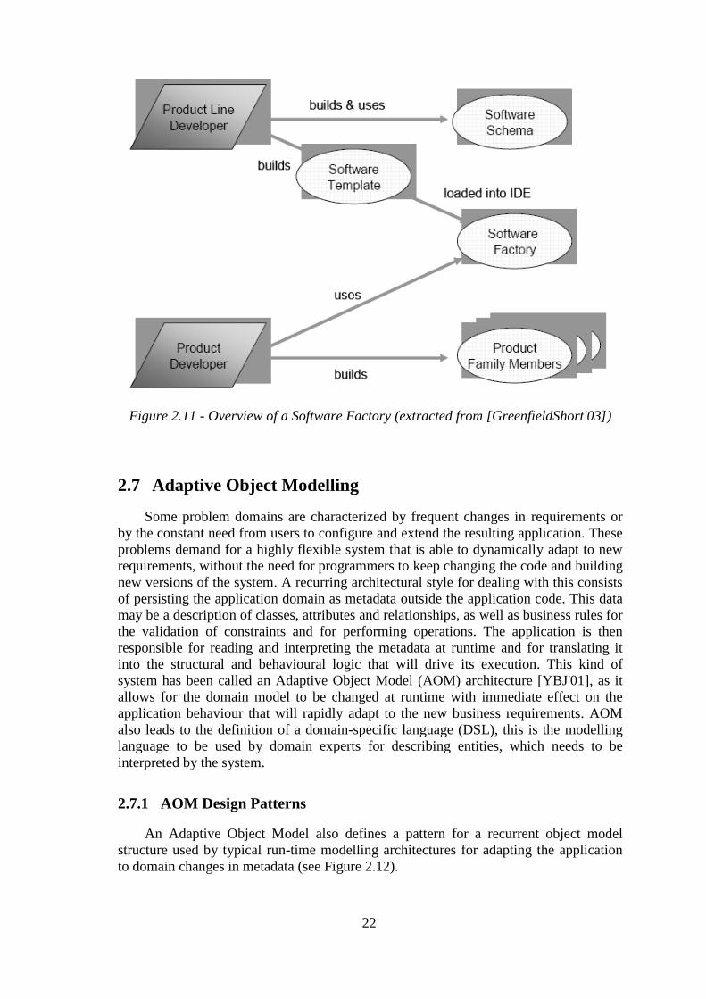
Figure 2.11 - Overview of a Software Factory (extracted from
[GreenfieldShort'03]) ............................................................................ 22
Figure 2.12 - AOM Common Structure (extracted from [YBJ'01]) ........................ 23
Figure 2.13 - AOM Extended Architecture (adapted from [WebAOM]) ............... 24
Figure 2.14 - AOM Application (extracted from [YBJ'01] ..................................... 25
Figure 3.1 - Typical application structure ............................................................... 29
Figure 3.2 - The importance of models ................................................................... 29
Figure 4.1 - Architecture of the FV-RAD framework ............................................ 33
Figure 4.2 - Metadata base interface definitions ..................................................... 35
Figure 4.3 - Base implementation of metadata Interfaces ....................................... 38
Figure 4.4 - Base definition of data types ............................................................... 38
Figure 4.5 - Models and Worlds .............................................................................. 40
Figure 4.6 - FV-RAD UML based Metamodel ....................................................... 41
Figure 4.7 - Model interpretation Interfaces ........................................................... 42
Figure 4.8 - Transaction based collections .............................................................. 44
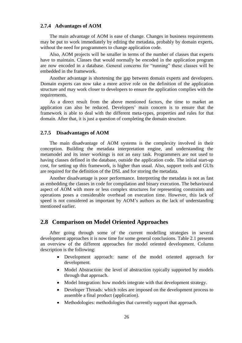
Figure 4.9 - Concrete classes for model interpretation ........................................... 45
Figure 4.10 - Prototype editing architecture ............................................................ 48
Figure 5.1 -The "Company" model ......................................................................... 51
Figure 5.2 - Defining the "Employee"entity type.................................................... 53

Figure 5.3 - Defining the "degreeType" enumeration ............................................. 54
Figure 5.4 - Extending a "DomainWorld"............................................................... 54
Figure 5.5 - The "Employee" extended entity type ................................................ 55
Figure 5.6 - Prototype invocation ............................................................................ 56
Figure 5.7 - Prototype main window ....................................................................... 56
Figure 5.8 - Running the "Company" prototype ..................................................... 57
Figure 5.9 - FV-RAD's Domain Log ....................................................................... 58
Figure 5.10 - FV-RAD's documents (".FVX") ........................................................ 59
Figure 5.11 - BusPlanner application ...................................................................... 60
Figure 5.12 - BusPlanner model diagram................................................................ 61
Figure 5.13 - FV-RAD and Association Classes ..................................................... 62
Figure 5.14 – Converting a N-N directed Association Class .................................. 62
Figure 5.15 - BusPlanner transformed model adaptation ........................................ 63

List of Tables
Table 2.1 - Comparing Model Oriented Approaches .............................................. 27
Table 4.1 - FV-RAD components and assemblies .................................................. 34
Table 4.2 – Field boolean classifiers ....................................................................... 36
Table 5.1 - "Company" model definition ................................................................ 52

ix
Abbreviations
AOM Adaptive Object Modelling
AOSD Aspect Oriented Software Development
API Application Programming Interface
CASE Computer Aided Software Engineering
DSL Domain Specific Language
FV-RAD Field Values based Rapid Application Development
GIST Gestão Integrada de Sistemas de Transportes
GSD Generative Software Development
GP Generative Programming
GUI Graphical User Interface
J2EE Java 2 Enterprise Edition
MDA Model Driven Architecture
MDD Model Driven Development
MDE Model Driven Engineering
MDSD Model Driven Software Development
WWW World Wide Web
WPF Windows Presentation Foundation
MOF Meta-Object Facility
OCL Object Constraint Language
OMG Object Management Group
OO Object Oriented
OPT Optimização e Planeamento de Transportes, SA
ORM Object Relational Mapping
PDM Platform Dependent Model
PIM Platform Independent Model
PSM Platform Specific Model
RAD Rapid Application Development
RUP Rational Unified Process
SF Software Factories
SQL Structured Query Language
UI User Interface

x
UML Unified Modelling Language
VB Visual Basic
VS Visual Studio
XMI XML Metadata Interchange
XML Extended Markup Language
XP Extreme Programming

1
1 Introduction
Software development is still a growing business with an increased history in
applying new methodologies for its production. It is however strange to notice that, after
all this time, it generally still comes down to the manual writing of thousands or
millions of lines of code. In an era where the human error factor has been largely
compensated through the use of automation based processes and redundant quality
systems, it is discouraging to observe how such archaic, low level, error prone processes
are still the most applied practices in IT. The price is still being paid and it is reflected
in software quality and in deadlines that keep meeting failure.
Software development is slowly raising its abstraction level, and releasing humans
from the tedious repetitive tasks of low level programming. It is now time to relax our
finger tips and embrace the next paradigm in software development by applying finger
toes, to our models…
1.1 Methodologies and RAD
Early application development methodologies were typically devised as a waterfall
like model [Royce'87], where a series of disciplined and well defined phases take place
from requirement analysis and application design to the final implementation stages.
These more rigorous approaches were intended to minimize the cost of possible future
changes by predicting all system requirements and translating those into a big well
thought design up front.
The problem is that, in more evolving environments, where requirements tend to be
added or changed more frequently, it may happen that by the time the “final” design has
reached its implementation phase, the system has lost its utility by failing to comply
with the latest requirements. This is especially true when customers are only able to
decide on their actual needs by interacting with some sort of early version of a system
prototype.
Although predictive methodologies are still in use, more recent approaches to
development have progressively become more adaptive to changing requirements.
Application development has evolved into a more iterative and incremental process (ex.
2
RUP [JBR'99]). The idea was to minimize the time between gathering requirements and
producing the first or the next software release, being it an intermediate prototype or a
specific application component.
Some methodologies, like Rapid Application Development (RAD), presented by
James Martin in 1991 [Martin'91], have set changing requirements as their stepping
stone to development. RAD encouraged the rapid production of application prototypes
in short successive development cycles, supported by CASE tools, as a way for the
developer to validate and gain immediate feedback on customer’s requirements.
The formal methodology as described by James Martin is no longer practiced, but
its principles are still in use. Current Agile Software Development methodologies (ex.
SCRUM [SchwaberBeedle'02], XP [BeckAndres'05]) share a lot of those principles by
reducing the time between picking the next priority requirements and releasing the next
software version to a minimum, and thus bringing developers and stakeholders closer
together in the development process.
Although somehow lost in its original form RAD has now assumed a new broader
meaning. Whenever software automation tools or frameworks are in place, the RAD
acronym rises as the buzzword of choice which generally translates into speeding up the
time from requirement or design changes to implementation results.
1.2 Development at OPT
OPT (Optimização e Planeamento de Transportes, SA) is the company providing
the organizational context for this dissertation. Its mission is to provide excellence in
innovative and optimized systems for transport planning, management and public
information.
OPT is the joint result of two different sorts of expertise, one related to operational
research techniques in the field of transportation and optimization of resources, and
another dedicated to software development. The core product of the company is the
GIST system, a client-server modular system which allows for public transport
companies to plan their offer and manage their resources in an optimized way. Major
companies in Portugal use this system in a daily basis to manage their vehicle fleets and
drivers. There are other important products at OPT and the company is also very
committed to several projects related to public information.
Another important project OPT is involved with is the development of a light
version of the GIST system (GIST Light - Public Transport Planner). This version is
intended for smaller public transport companies and for research purposes within the
academic community. The idea is to provide a simple document based application that
provides a useful decision support system for the management of vehicle and driver
schedules.
Depending on the type of project OPT has different strategies for the development
process. Basically, there is a more strict documentation oriented process following
several standards that is applied to larger projects with several stakeholders, and there is
another more agile milestone oriented process that is used for instance in smaller
projects where requirements aren’t clearly defined upfront, or long projects whose
duration is an important factor for getting requirements outdated.
Although different development methodologies are used, there is a set of common
aspects that these share:
Even in larger projects some agility is always in place, in the sense that

3
requirements are rarely set up-front and development is always done in
several iterations and oriented towards the next highest priority
requirements.
Extensive use of evolving prototypes for validating, finding new
requirements, and demonstrating progress.
Modelling is detached from implementation; no software automation tools
are used.
Resort to UML class diagrams in design phase as the top modelling artefact.
Object oriented models like UML class diagrams are also used as the
preferred mean to discuss conceptual issues.
A huge effort of the development process is spent either on programming
the same recurring patterns repeatedly or trying to put these patterns in a
generic library that is used extensively throughout the project. These
patterns extend from functional logic to user interface and persistence.
The choice of which programming patterns to use, most of the times, could
be easily inferred by analysing the conceptual model, along with some
additional configuration detail.
1.3 Motivation and Goals
The aforementioned aspects of the development process at OPT have set the
prelude to the urging need of a tool that would easily and rapidly translate the modelling
effort involved in the conceptual design of applications into some form of usable
"material" like a functional library or a prototype. This "material" could be used for
testing or demonstration purposes and it would still play an important role as a design
proofing tool. However, the real impact in productivity should be achieved by using it
as the foundation backbone for the remaining development effort, by allowing it to
integrate smoothly with the implementation in an evolving way.
In a nutshell, for the modelling effort to become more profitable and provide added
value to each model, it should be able to answer some of the needs that arose from the
development process at OPT. These needs extend from requirements and design issues
to every aspect of the implementation process like functional logic, user interface and
persistence:
Requirements
Validating and gathering requirements within stakeholders through the use
of rapid prototypes.
Design
Testing the consistency of design models.
Using models to discuss and verify the impact of design decisions.
Base the implementation in design models.
Functional Logic
Rapid transition from model to model-aware domain library.
Attaching functionality to models by integration with implementation tools.
4
Overcoming model semantic limitations.
Running a model for testing purposes.
User Interface
Raise intelligence level on current UI frameworks by making them model-
aware.
Automatic generation of model based user interface for prototyping.
Persistence
Generating persistence schemas
Automatic model based persistence.
The answer to these needs called upon the development of the framework in the
scope of this thesis. It should be able to at least tackle some of the challenges that were
being proposed. Being an inner development at OPT meant that, besides facilitating a
better knowledge of its workings and use, there was an additional advantage that it
could be tailored to fit company specific needs.
The "GIST Light" project described earlier, particularly a more limited pre-release
version called "Bus Planner", finally triggered the will for this framework. The fact that
it is a single user flat-file based application somehow limited the scope for the initial
aim of the intended framework, reducing the risk for project dispersion.
Being a RAD framework that would rely on the description of entity Fields and
allow the control of their changing Values, it was decided to name it "FV-RAD" (it
seems all RAD related acronyms had been used up). It could stand as well for "Flat-file
Version", "Fast Velocity", or “Framework Version", just take your pick.
Having decided on the needs and boundaries that would define the initial scope of
this thesis, it was now time to have a clear understanding of what would be its main
goals and constraints:
Goals
To build a framework that allows for the integration of an application's
conceptual model within its implementation, thus becoming model-aware.
To demonstrate and test design models by rapidly producing executable
prototypes.
To allow for prototypes to evolve until a final release is reached, by
progressively refining its functionality with the implementation tools (ex:
code extensions).
To spread the framework across all aspects of the implementation process:
functional logic, user interface, and persistence.
To apply this framework to a real project.
Constraints
Models are based on a subset of UML class diagrams.
Only single user flat-file based persistence should be supported.

5
1.4 Thesis Statement
Software conceptual models are currently used in various ways. They might be
totally detached from the implementation and used solely for design planning purposes,
or they might somehow integrate with the implementation throughout the development
process. This gap between model and implementation is also reflected on the structure
and level of detail provided by these models. In an environment with frequent evolving
requirements, a high level of detachment generally imposes a low level of detail so that
the effort on keeping these models up-to-date is reduced; highly detailed models would
tend to limit model usage to an initial design baseline.
The bottom line is that a low level of interaction between model and
implementation adds little value to each model. Shortening this gap and providing
model usage and integration through all the development process, is one of the
challenges we face today. Doing it in a way that smoothly integrates with the
technology and tools provided by the implementation process of a specific organization,
is another challenge that is faced in the scope of this thesis.
The statement of this thesis is that, by embedding the model in the implementation,
through the use of a framework inspired on Adaptive-Object-Modelling techniques and
supported by a simple configuration process, we are able not just to make the
implementation model-aware but also to adjust and close model semantics to a
particular implementation technology. The bridge is established between highly abstract
constructs provided by models and low level control provided by specific
implementation tools. The advantages are obvious; the model-implementation gap is
shortened in a way most suitable to developer needs. Models will have a direct impact
on application development results and the organization will benefit from their added
value and use.
Also, by providing an initial "raw" implementation of the model, through the
framework's interpretation of the model's domain, and by adding an intelligent User-
Interface library that is model-aware and some type of persistence mechanism (ex:
XML), all main aspects of an application spectrum should be covered, and the ability to
provide a fully working prototype should be acquired. The application core will be
centred on the execution of its domain model. Translating requirements into working
prototypes will be effortless, and final project outcome will be reached through the
progressive refinement of implementation details. This refinement process should
extend model semantics and provide additional functionality by "filling the holes"
where the framework lacks its grasp.
The framework hereby described is not intended to be a complete environment but
rather a simple practical tool, suited and familiar to a particular development process,
and inspired on premises that resemble the initial RAD goals established by James
Martin.
1.5 Thesis Outline
The first chapter gives an introduction on RAD, modelling, and how modelling
integrates the development process. It proceeds by putting these in the perspective of the
hosting company and identifying the needs that originated this work. Finally the
motivation and goals that led to this thesis are presented and concludes with the thesis
statement.

6
Chapter 2 gives a state of the art analysis of modelling strategies and model
oriented development. Special emphasis is put in generative software development and
AOM. These approaches are finally classified and compared in the last section.
Chapters 3 and 4 present the framework (FV-RAD) developed by the author in the
scope of this thesis. After an initial contextualization, with specific technical goals and
limitations intended for the first release (chapter 3), main technical issues are described
in detail for the full understanding of the framework’s architecture.
Chapter 5 gives a practical approach to using the developed framework. Use case
considerations are explained initially. Examples are presented in the scope of a simple
demonstration and the “Bus Planner" project currently under development at OPT
(modelling issues).
Chapter 6 presents final results and conclusions, and discusses the next steps for
evolving the framework.
Finally, some references and appendixes are provided as support for the reader of
this thesis.

7
2 Modelling and Development
Modelling is an integral part of almost every development process in use today. As
methodologies evolve, models are getting closer to the problem space rather than
imposing a specific solution. Future trends are becoming directed towards finding the
best modelling languages and architectures for solving general purpose or specific
domain oriented problems. It is thus important to situate models in the current
development context and analyse how current approaches deal with the gap between
highly abstract modelling languages and low level platform oriented implementation
assets.
2.1 Modelling
2.1.1 The Need for Models
Design models play an important role in software development. Whether of a
general purpose nature like UML based models [BRJ'05, RJB'05] or custom built to suit
a particular software domain like DSLs [DKVCzarneckiEisenecker'00, '00], they
capture system variability into design abstractions that are used as the baseline for the
implementation process. They also provide a way of formalizing requirements into
structural and behavioural constructs that define system concepts, functional logic, and
constraints. Other important characteristics of software models are presented next:
Models resume a reality or a solution to a problem.
Models are able to define a conceptual plan (master plan).
Models may translate design choices and direct the implementation of software.
Models define a common language for discussing and understanding problems
and solutions.
Models are succinct, they don't have to draw the whole picture but rather
synthesise the main structural and behavioural aspects of a system. Also, a small
set of related modelling constructs has the ability to pass a lot of information

8
through their huge semantical power. In a rough way, models allow the
definition of very much with very little; this particularly applies to graphical
modelling.
Models are independent from implementation technology. A decrease in
abstraction implies an additional weight in complexity and detail as you get
closer to specific implementation technology.
Models for design purposes must be computational as they can be tested and
simulated; this also means they must be syntactically and semantically consistent
(unambiguous).
As methodologies evolved from more predictive to more adaptive, the importance
of models, as a way to rapidly translate design into prototypes or into implementation
was considerably more demanding. Stakeholders want to be able to see results from the
early stages of the development process in order to validate their compliance to
requirements, and developers want to continuously probe for costumer needs. The
highly synthetic and semantical power of models supported by the right set of tools
allows just for that to happen.
2.1.2 Metamodelling
Metamodels are models used for defining model structure. They are important in
the context of the specification of the UML standard for modelling, which uses MOF
(Meta Object Facility) as the meta-metamodel for the definition of the meta-models that
give support to the UML specification [OMG'09]. Metamodelling can be seen as a
multi-level structure where each level describes instances from the previous level. The
OMG (Object Management Group) has 4 metalevels, M0 for final instances (objects),
M1 for the models with classes describing the objects, M2 for the metamodels with
classifiers describing the models, and finally M3 for the meta-metamodels that describe
metamodels (see Figure 2.1) .
Figure 2.1 - The four metalevels of OMG

9
Metamodels are also used for the construction of Domain Specific Languages
(DSLs), by describing the abstract syntax of such languages (graphical or textual). They
will be used as the basis for model-validation, model-to-model and model-to-code
transformations in the context of generative methodologies (see sections 2.4, 2.5 and
2.6). They are also used for the definition of tools and frameworks that are able to adapt
to the respective domain (see section 2.7).
2.2 Software Reuse
Software reuse is about increasing the level of productivity in software
development [ClementsNorthrop'02]. It’s been quite some time since subroutines were
the only way of software reuse. From then, successive evolutionary steps have raised
the level of software productivity and progressively reduced the need to write code (see
Figure 2.2), although still not enough to satisfy the market demand for more and higher
quality software.
Figure 2.2 - Software reuse, from past to present
Object oriented programming [Meyer'97], component based development
[SGM'03], object oriented frameworks [FayadSchmidt'97, Johnson'92, Lewis'95], and
the study and classification of important design patterns [GoFFowler'03, '95] have all
been important breakthroughs for software reuse. The combined use of these and other
emerging technologies like aspect-oriented programming [Laddad'03], at different
abstraction layers, and a clear shift towards a paradigm for design reuse, through
modelling and development of software production lines, has led to the current state of
the art in software reuse through generative software development methodologies
[Czarnecki'04] (also see sections 2.4, 2.5 and 2.6).

10
Models have never been as important for software reuse as they are today. As the
level of abstraction for software development raises, modelling artefacts like Domain
Specific Languages (DSLs) provide the ideal mean of expressing these abstractions and
for translating these into a reusable architecture. The emphasis is no longer on
composing an architecture from general components and frameworks, but rather on
generating an architecture from DSL based configurations, isolating the developer from
the cross-cutting concerns that are part of the architecture’s infrastructure.
Adaptive Object Modelling (AOM) techniques [YBJ'01] have also been an
important part in software reuse by empowering the user/developer to make run-time
changes to the application by editing models based on general purpose DSLs. These
models are interpreted at run-time by specialized frameworks, allowing the application
to easily adapt to new requirement changes without the need for extra coding or
compilation (see section 2.7).
The market demand for more and higher quality software is still far from being
fulfilled, but recent generative, adaptive technology trends and others open a new
window for the future, where models and model oriented development will definitely
play an important role.
2.3 Development with Models
In this section, a comparison is made between different model oriented strategies in
development methodologies. This analysis is made from the perspective of dealing with
the model-implementation gap and its impact on model usage.
2.3.1 Detached Modelling
In this strategy models are totally detached from the implementation.
This is still one of the most used model based development strategies. Models are
particularly useful at the beginning of the development process in order to guide the
implementation process and they are used as a reference there upon. Unless it is a
critical system or a big project with few evolving requirements where a more detailed
specification is needed, these models should be kept simple in order to illustrate main
system functionality and to reduce the effort on keeping the models updated as
requirements evolve.
2.3.2 Executable Modelling
This strategy is based in executable models that embed the implementation.
Some tools allow the definition of models for every aspect of the development
process, from functional logic to user interface and persistence. These general purpose
tools may even include some kind of high level programming language like OCL
(Object Constraint Language) [RichtersGogolla'99] to detail model constraints or
operations. Although these tools are considerably powerful, the problem is that they
lack flexibility in low level control of technology. The conceptual and technological gap
between existing modelling and implementation technologies has prevented good
support for true integration between high level modelling and low level implementation
constructs. Combining the power of a high level modelling and low level
implementation technology into a single fully integrated development tool (no code

11
generation) is still a challenge to be overcome. An interesting attempt has been done by
[RFBO'01] trying to devise an architecture for a UML virtual machine. There’s also a
trend on applying UML virtual machines for MDA [MellorBalcer'02].
Another important aspect is that these are general purpose one size fits all abstract
modelling languages (as opposed to DSLs), not oriented to a specific domain, which
means there will be a semantic gap between these models and the domain.
2.3.3 Design-Time Modelling
Roundtrip Engineering
This strategy tries to synchronize the models with the implementation.
This is typically achieved through code generation and reverse engineering
techniques (roundtrip engineering). Unless there is a deep integration of modelling tools
within the development environment and its libraries, the effort put on synchronizing
implementation code with modelling constructs, particularly after initial code generation
phases, may be discouraging. When the programmer starts adding additional code and
manually changes the implementation, it will be difficult to decide whether this code
should be reflected in the model or kept "hidden" within the implementation. Even
small things like changing the name of an attribute or adding a parameter may have to
be synchronized, adding an additional overhead to the development effort. Models may
end up being too much detailed and their abstraction level reduced in order to comply to
a specific development environment and programming language. CASE tools typically
explore this kind of modelling orientation [KSSSZ'02] (which is probably also why
their success has been quite disappointing).
Generative Development
This strategy generates the implementation from models. Manual written code is
added but no reverse-engineering is allowed [Czarnecki'04].
Generative software development generates all infrastructure code from DSL based
models. These are highly abstract modelling languages that try to match a particular
domain in the problem space (see sections 2.4, 2.5 and 2.6). By being domain oriented
and more focused on the problem rather than on the solution, they are isolated from the
specific platform where the implementation is due, thus ensuring better independence
from technology variation or evolution. This high degree of abstraction also means that
reverse engineering is practically impossible, as it would impose a level of
implementation based detail on models (from the solution space) that is contradictory to
its goals.
Some tools may focus on full code generation, but the aim is to provide code
generation for the entire domain architecture infrastructure and add code to fill the gaps
where the models or the generator are unable to cope with.
Generative methodologies are also directed toward the implementation of software
production lines for given software system families.
2.3.4 Run-Time Modelling
In this strategy the model is embedded in the implementation. The implementation
is model aware, and directed by the interpretation of the model.

12
This scenario is a good trade-off between the high level abstraction of a model and
low level control of implementation technology. The abstraction level of the model is
not compromised because the model doesn't have to be aware of the implementation
technology but rather the opposite. By embedding the model, the decision on how the
implementation attaches to its structure and behaviour is left to the implementation
itself. As such it opens the possibility for the rising of tools and frameworks that
manage this integration process. These may go from simple user interface gadgets, to
more complex entity life-cycle management frameworks with prototyping capabilities
and full support for model semantics.
Adaptive Object Modelling [YBJ'01] (see section 2.7) provides an approach with
an architectural style for this kind of methodology and the framework developed within
this thesis follows some of its principles and inspiration.
2.4 Generative Programming
Generative Programming (GP) [Czarnecki'04], has been the inspiration behind
some of the most advanced approaches to modelling and development in use today like
Model-Driven Software Development and Software Factories which will be presented
later (sections 2.5 and 2.6).
It became popular mainly through Krzystztof Czarnecki’s and Ulrich Eisenecker’s
book on Generative Programming [CzarneckiEisenecker'00], who defined GP as
follows:
Generative Programming is a software engineering paradigm based on modeling
software system families such that, given a particular requirements specification, a
highly customized and optimized intermediate or end-product can be automatically
created on demand from elementary, reusable implementation components by means of
configuration knowledge.
The main focus in GP is software reuse. It advocates that traditional forms of reuse
like Object Oriented Programming, Frameworks, Components and even Design
Patterns, have been unable per se to deliver the promise of software reuse. A shift of
paradigm is needed towards modelling and developing software system families rather
than individual systems. GP is a system-family approach (also known as product-line
engineering) which exploits the commonalities among systems of a given problem
domain and manages its variabilities through a systematic approach. The creation of a
system-family member is automatically generated from system specifications that are
able to express those variabilities in one or more textual or graphical domain-specific
languages (DSLs). The emphasis is on the configuration of the problem space and its
automated transformation to the solution space through the use of domain-oriented
modelling languages, rather than developing and composing individual components into
a final application from the start (see Figure 2.3).

13
Figure 2.3 - Mapping between problem space and solution space (adapted from
[Czarnecki'04])
Typical GP systems separate development into two processes, domain engineering
and application engineering. Domain engineers define the structure of the DSLs needed
to tackle a particular domain, and produce the necessary reusable assets (components,
generators, analysis and design models, user documentation, etc.) that will be used by
application engineers to transform their DSL specifications into implementation
abstractions like elementary components connected through some glue generated code.
The transformation in Figure 2.3 can be viewed recursively. Someone’s problem
space may be someone else’s solution space, thus several transformations may be
chained together to produce a final solution. At the same time several problem related
spaces may map into the same solution space (ex: different aspects of a problem
represented using different DSLs). Also the same problem space may produce results in
several solution spaces. These related spaces and transformations end up producing a
graph that corresponds to the idea of a network of domains [Neighbors'80] where the
solution space of a domain exposes a DSL that is implemented by transformations to
other DSLs in other domain implementations.
The mapping from problem to solution space may also benefit from an aspect-
oriented approach [Laddad'03] [WebAOSD] that will allow for the composition of
components in the solution space into well encapsulated aspect based modules. This
isolates the application developer from the cross-cutting concerns that will be part of the
domain infrastructure.

14
Figure 2.4 - Generative programming and related fields (extracted from
[Czarnecki'04])
Figure 2.4 shows a perspective on how GP’s related fields intersect with the
problem-mapping-solution spaces. For the current status on GP you may consult
Krzystztof’s web site on [WebCzarneckiHelsen].
2.5 Model-Driven Software Development
Model-Driven Software Development (MDSD) [StahlVölter'06], also known as
Model-Driven Development (MDD) and Model-Driven Engineering (MDE), is a
horizontal approach to modelling based on Domain Specific Languages (DSLs), model
transformations and generative techniques. It has a strong orientation towards domain
related aspects of software development rather than programming or computational
ones. The emphasis is on the engineering principles that lead to the enhancement of
development efficiency, quality, maintainability and reusability. This is achieved
through the automation of all redundant artefacts that repeatedly populate and define an
application’s infrastructure. Redundancy is delegated to a generative software
architecture that knows all the construction principles and programming models from
the various layers and aspects of a specific domain and is able to compose and assemble
a domain related application from its building blocks. Infrastructure code is generated
from formal models using one or more transformation steps (model-to-model or model-
to-code, see Figure 2.5). Cross-cutting implementation aspects will be centred in one
place, for example in the transformation rules, just like infrastructure bugs. This
separation of concerns [Laddad'03] promises better software maintainability by
avoiding redundancy and by isolating technological changes. Additional application
domain specific code is then added through protected code areas or using well known
design patterns [Frankel'03].

15
Figure 2.5 - MDSD, from model to code (extracted from [WebVölter])
Complexity is managed through highly abstract, problem oriented, modelling
languages (DSLs) for the programming and configuration of various system aspects.
This means that modelling artefacts will be focused more in the problem rather than the
solution and are isolated as possible from its platform implementation. This level of
abstraction imposes a forward only generative process, since the semantic gap between
models and implementation code is just too high to allow reverse engineering.
MDSD clearly separates the development of the domain architecture infrastructure
from the development of the domain related application. This separation defines the
assignment of team roles as domain architects and application developers within a
MDSD project.
Figure 2.6 presents a classified overview of the core concepts involved in MDSD.
These concepts are centred around three important aspects: the DSLs that define a
specific domain in the problem space for a given software family, the models built on
those DSLs by application developers, and the transformation between these models
and the target platform. These aspects will be further detailed in the next subsections.

16
Figure 2.6 - MDSD Core Concepts (extracted from [WebVölter])
2.5.1 Domain Architecture
Building a domain architecture [Evans'04] demands a deep knowledge of a
particular domain and may be figured as a two step process. The first step should be the
domain analysis and manual generation (modelling and coding) of a reference
model/implementation where all best practices and development patterns have been put
to use, and where all required frameworks and supporting technologies (platform) have
been set. The second step should derive the domain architecture from this reference
model/implementation, not just in terms of the meta-models and domain specific
languages that define the abstract and concrete syntax and semantics of the reference
domain models, but also the transformation process and rules that will eventually result
in the static code that defines the domain infrastructure on which application developers
will build upon.
The resulting artefacts will be the meta-models and DSLs that will comprise the
domain related aspects of that software system family, the templates and model
transformations that will direct the generative process, and the support frameworks and
material that will be the base of the semantically rich platform on which applications are
built. These artefacts are not end pieces of a first phase waterfall based development
process but rather a continuous work in progress from domain architects that, just like
their application developer counter-parts, should have an iterative and incremental
approach to implementing and improving the architecture.
Once architectures, models, and transformations have been defined, they can be
used in the sense of a software production line for the production of diverse software
system families. This is the manufacturing orientation of MDSD. As we can see, the
focus is more directed towards finding the right development methodology for a given
domain related problem through a specific platform rather than implementing a generic
development environment as a one for all process.
2.5.2 Application Development
In MDSD, application developers are released from the tedious task of having to
program the same constructs over and over again whenever they build a new domain

17
related application or whenever they incrementally add a new feature to it. The domain
architecture is devised by architects and it will formalize and support that domain.
Application developers may use the reference model/implementation as an orientation
guide, and may concentrate on what they do best, designing the application by
modelling it using the DSLs defined in the domain architecture, and coding the
remaining domain specific logic (business logic) that was left out of the static
generation process. Figure 2.7 shows a simple generative architecture used by
application developers to devise a solution starting from a model written in a particular
DSL and integrating manually written code to fill application specific aspects left out of
the infrastructure. The resulting artefacts will be the DSL models, generated static code,
and extended domain logic code that could not be expressed using the DSL.
Figure 2.7 - A generative architecture (extracted from [WebVölter])
2.5.3 Model Driven Architecture
Model-Driven Architecture (MDA) [Frankel'03] is a standardization initiative from
the OMG (Object Management Group) with respect to model-driven development. It
does not cover the entire MDSD spectrum but may be regarded as a specialization of
MDSD (see Figure 2.8). The primary motivations were interoperability (through
standardization) and portability (platform independence) of software system.
MDA uses MOF (Meta Object Facility) as the meta-metamodel, for the definition
of metamodels. As expected from the OMG, UML plays a central role in MDA which
recommends the use of UML profiles [FuentesValecillo'04] as a concrete syntax for a
DSL. OMG has even made some adaptations in the context of UML 2.0 to ensure it all
fits well. OCL expressions are used to specify static semantics.
A domain model in MDA can be independent from platform (PIM - Platform
Independent Model) or platform specific (PSM - Platform Specific Model).
Transformations may occur between models (recommended) or directly from PIM-to-
code. Platforms are also described via a metamodel. PDMs (Platform description
Models) are used in order to enable transformation to platform specific models. OMG’s
QVT (Query/View/Transformation) is expected to be the standard used for model-to-
model transformations by defining the conversion process between source and target
metamodels.
Another objective of many MDA representatives is to provide a foundation for
executable UML models [MellorBalcer'02], whether they are interpreted by a UML
virtual machine or completely compiled to a target platform through model
transformations. By using general purpose models to be directly executed on a lower-

18
level platform we are in fact raising the abstraction level of a programming language
based on models, meaning there will be a semantic gap between this language and a
specific domain.
Basically, MDA instantiates MDSD with a set of standards that clearly define the
mapping of a model to an existing platform.
Figure 2.8 - MDA specialization on MDSD (extracted from [WebVölter])
2.5.4 Architecture Centric MDSD
Architecture centric MDSD (AC-MDSD) is a specialization of MDSD that
conceptually overlaps with MDA. The aim is to provide an architecture oriented domain
(ex: architecture for client-server business applications) by generating the architecture
infrastructure for that domain from specialized DSLs called design languages. These
languages are usually based on UML profiles and contain architectural concepts that are
as abstract as possible.
The generation process will typically create an implementation framework that
contains the architectural infrastructure code (the skeleton). This is usually achieved
through single-step model-to-code transformations based on templates. Manually
written code is then added to the implementation in protected areas or through suitable
design patterns to complete a finished product (application).
Design languages, templates and target platform will constitute the generative
architecture for supporting a given software system family.
2.6 Software Factories
The concept of “software factories” was introduced by Microsoft
[GreenfieldShort'03] [GreenfieldShort'04] to define a broad approach whose final intent
is the industrialization of software development. This intent should provide the means
through which application assembly becomes more cost effective through systematic
reuse of development assets and processes. Microsoft’s vision encompasses the

19
establishment of software supply chains focusing on the mass customization of software
products.
By looking at the complete product-line engineering process, sometimes referred as
“doing product lines the Microsoft way”, software factories are much wider in scope
than MDSD. In fact, model-driven development is one of the main cornerstones on
which software factories rely and they share much of its concepts and techniques. The
convergence of software product lines, component-based development and model-
driven development, and the integration of these into a cohesive approach that supports
new IDE oriented tools and practices are the key ideas that thrive from the innovation
axis of software factories.
As in MDSD [StahlVölter'06], software factories have two essential roles in the
development process, one more directed towards the product line development that
culminates in the production of a software factory, and another that uses the software
factory for the development of a software product or product family.
2.6.1 Product Line Development
A software product line separates the commonalities and known forms of variation
of a specific product family in order to automate their development
[ClementsNorthrop'02, CzarneckiEisenecker'00, Parnas'76].
The product line developer will start by defining a set of DSLs for that product
family. A simple factory could be based on a framework that addresses a specific
domain, and the DSL would reflect the variability points in the framework to be filled
through code generation. However, it is not always possible to build a framework for
the implementation of a highly abstract DSL. In that case, progressive transformations
to less abstract models may be needed before producing the executables. When models
stack like this it becomes useful to categorize them as a layered grid. That is the next
step in the product line development.
The layered grid for categorizing models has columns to represent specific
concerns like presentation, business, persistence, deployment, etc. The rows represent
decreasing levels of abstraction like conceptual, logical and implementation layer. Each
cell will represent a viewpoint from which software can be specified (see Figure 2.9).
By positioning the DSLs within the grid and defining the mappings between the
cells where partial or full automation is supported, a graph of viewpoints is produced
that will describe the set of specifications and transformations needed to produce a
software product. This graph is called a “software schema”. Figure 2.10 presents a
simple software schema instantiating the viewpoints for the layered grid in Figure 2.9
for the production of web based business applications.

20
Figure 2.9 - A layered grid with different viewpoints for categorizing models (extracted
from [GreenfieldShort'03])
After the software schema is defined, production assets must be built, like editing
tools and automation tools for transforming models, and processes used for describing
the use of implementation assets. All these assets will be used by product developers to
implement product family members, and will be collected into an artefact called a
“software template”.
A software factory is finally reached when a software template is plugged into an
existing IDE (like Visual Studio), all assets will be integrated as an automated product
line where software product customization and assembly may take its place.
Software factories may also be used to produce other software templates that will
integrate other software factories of more specialized family members. This opens the
way for the formation of automated supply chains for full customization of software
family members.

21
Figure 2.10 - A Software Schema (extracted from [GreenfieldShort'03])
2.6.2 Product Development
By using a software factory (see Figure 2.11), product developers will be provided
with all the necessary editors, tools, and specifications to rapidly assemble family
members. After configuring the software factory appropriately, they will build DSL
based models for each viewpoint within the “software schema” and there will be tools
for translating those into lower abstraction models or into executables. Final results will
be reached through progressive refinement of the models and through framework
completion of specific member details, until all the software schema is fully populated
on every existent viewpoint. At times, a bottom up approach may be used, by generating
the necessary test components upfront that will be used for testing the various pieces of
the working product as development progresses.
22
Figure 2.11 - Overview of a Software Factory (extracted from [GreenfieldShort'03])
2.7 Adaptive Object Modelling
Some problem domains are characterized by frequent changes in requirements or
by the constant need from users to configure and extend the resulting application. These
problems demand for a highly flexible system that is able to dynamically adapt to new
requirements, without the need for programmers to keep changing the code and building
new versions of the system. A recurring architectural style for dealing with this consists
of persisting the application domain as metadata outside the application code. This data
may be a description of classes, attributes and relationships, as well as business rules for
the validation of constraints and for performing operations. The application is then
responsible for reading and interpreting the metadata at runtime and for translating it
into the structural and behavioural logic that will drive its execution. This kind of
system has been called an Adaptive Object Model (AOM) architecture [YBJ'01], as it
allows for the domain model to be changed at runtime with immediate effect on the
application behaviour that will rapidly adapt to the new business requirements. AOM
also leads to the definition of a domain-specific language (DSL), this is the modelling
language to be used by domain experts for describing entities, which needs to be
interpreted by the system.
2.7.1 AOM Design Patterns
An Adaptive Object Model also defines a pattern for a recurrent object model
structure used by typical run-time modelling architectures for adapting the application
to domain changes in metadata (see Figure 2.12).

23
Figure 2.12 - AOM Common Structure (extracted from [YBJ'01])
This meta-model is based on a set of smaller design patterns, and will be
responsible for loading the metadata, interpreting it, and changing the application
behaviour and integrity rules, accordingly.
The TypeObject pattern [JohnsonWoolf'97] is used to decouple instances (objects)
from their classes (types) so that those classes may be implemented as instances. It
allows for classes to be created dynamically at run-time without the need for
recompilation. This pattern is used in Figure 2.12 to separate an Entity from its
EntityType and a Property from its PropertyType .
Entities have attributes which are implemented through the Property pattern
[JosephYoder'98]. This pattern enables individual objects to augment their state by
providing mechanisms for accessing, altering, adding, and removing properties or
attributes at run-time. This can be done using a dictionary, vector or lookup table. Each
property within a given entity will refer to its type and hold a particular value for that
type.
Associating Properties to Entities at each abstraction level (instances and types) by
combining the TypeObject and Property patterns forms a square shaped pattern like the
one shown on the left side of the picture. This pattern, called TypeSquare, is a very
common theme in many AOM architectures. It shows that an EntityType defines a set
of Property Types, one for each Property of the Entities assigned to that EntityType.
The patterns presented till now are more directed towards a structural description
of the domain, but the behavioural aspect of AOM is also a very important issue. The
Strategy pattern [GoF'95] is used to define the behaviour of Entity Types. Basically, a
Strategy is an object that represents an algorithm. Strategies are represented in the
model as RuleObjects [Arsanjani'01]. These Rules may be used for validating purposes
by enforcing constraints or for implementing operations on Entity methods. This pattern
might also be used to validate Properties through their PropertyType. A Rule may be a
simple primitive rule (PrimRule) or may be a composition of other rules
(CompositeRule). Rules can be built up at run-time to represent a particular workflow
process or a validation procedure. Lookup tables, grammar-oriented approaches
[Arsanjani'01], workflow architectures [Manolescu'00], or other approaches may be
used for defining rules.
Relationships, also known as Associations or Accountabilities, are properties that
refer to other entities. These could be implemented by deriving the Property class into
Attribute and Association sub-classes. However, Entity-Relationship modelling in

24
AOM usually separates attributes from relationships. A way to do this is to use the
Property pattern twice, one for simple attributes and other for associations. Associations
(AccountabilityType) would then refer to the Entity Types involved on the relationship.
Other important design patterns for building adaptable systems, used in conjunction
with the above, are Composer, Interpreter and Builder [GoF'95]. Composer is used for
building dynamic tree like structures for types and rules while Interpreter and Builder
are used for building the structures from the metadata and for their run-time
interpretation.
2.7.2 Extended Architecture
Figure 2.13 shows an extended version of the AOM architecture adapted from the
AOM site [WebAOM].
Figure 2.13 - AOM Extended Architecture (adapted from [WebAOM])
The right side, related to information that is persisted in the metadata store,
highlights the structural (classes, attributes and relationships) and behavioural aspects
that define the Knowledge level of the system with available Types and Rules. The
Operational level (at the left) represents all instances assigned to those Types and on
which the Rules are to be applied. This level is related to application data that is
typically persisted in a specific domain database.
The above architecture is still a general reference for an AOM architecture from
which new concepts may build upon. A new architecture could for instance be able to
support component modelling where each component would aggregate some classes
from a generic domain to be reused in similar applications [CDLM'05].

25
2.7.3 Developing AOM applications
Developing AOM applications involves several activities:
Defining the business entities, their properties, rules and relationships. This
is where the domain experts take an important role.
Developing an engine for instantiating and manipulating those entities. This
activity typically implies building a framework for reading and interpreting
at run-time the metadata that was defined in the previous activity. This is
one of the more important and complex activities in this process. However
the difficult part is doing it for the first time. After that, the acquaintance
with the design patterns is established, and it is just about reusing the same
architecture. This framework may also include other aspects of the dynamic
adaptation to requirements like User Interface automation. An AOM always
involves the development of some kind of framework. The alternative is to
use an existing one, if it exists.
Developing tools for creating, editing and storing the metadata descriptions
that will be loaded an interpreted in run-time.
Figure 2.14 presents a typical architecture for an AOM application. Metadata is
stored in XML files. These files are parsed and interpreted at run-time by using the
Interpreter and Builder patterns mentioned earlier. Metadata is then structured for a
specific component responsible for instantiating and manipulating the domain objects
through their type descriptions (entity types). These objects (entities) may then be
persisted to a database.
Figure 2.14 - AOM Application (extracted from [YBJ'01]
26
2.7.4 Advantages of AOM
The main advantage of AOM is ease of change. Changes in business requirements
may be put to work immediately by editing the metadata, probably by domain experts,
without the need for programmers to change application code.
Also, AOM projects will be smaller in terms of the number of classes that experts
have to maintain. Classes that would normally be encoded in the application program
are now encoded in a database. General concerns for “running” these classes will be
embedded in the framework.
Another advantage is shortening the gap between domain experts and developers.
Domain experts can now take a more active role on the definition of the application
structure and may work closer to developers to ensure the application complies with the
requirements.
As a direct result from the above mentioned factors, the time to market an
application can also be reduced. Developers’ main concern is to ensure that the
framework is able to deal with the different meta-types, properties and rules for that
domain. After that, it is just a question of completing the domain structure.
2.7.5 Disadvantages of AOM
The main disadvantage of AOM systems is the complexity involved in their
conception. Building the metadata interpretation engine, and understanding the
metamodel and its inner workings is not an easy task. Programmers are not used to
having classes defined in the database, outside the application code. The initial start-up
cost, for setting up this framework, is higher than usual. Also, support tools and GUIs
are required for the definition of the DSL and for storing the metadata.
Another disadvantage is poor performance. Interpreting the metadata is not as fast
as embedding the classes in code for compilation and binary execution. The behavioural
aspect of AOM with more or less complex structures for representing constraints and
operations poses a considerable overhead on execution time. However, this lack of
speed is not considered as important by AOM’s authors as the lack of understanding
mentioned earlier.
2.8 Comparison on Model Oriented Approaches
After going through some of the current modelling strategies in several
development approaches it is now time for some general conclusions. Table 2.1 presents
an overview of the different approaches for model oriented development. Column
description is the following:
Development approach: name of the model oriented approach for
development.
Model Abstraction: the level of abstraction typically supported by models
through that approach.
Model Integration: how models integrate with that development strategy.
Developer Threads: which roles are imposed on the development process to
assemble a final product (application).
Methodologies: methodologies that currently support that approach.

27
Table 2.1 - Comparing Model Oriented Approaches
Development
Approach
Model
Abstraction
Model
Integration
Developer
Threads Methodologies
Detached Modelling
High - Application developer
Traditional development
Executable Modelling
High
(general purpose)
Model aware Application developer
Executable UML (MDA),
UML virtual machines
Roundtrip Engineering
Low
Model-to-code.
Code-to-model
(reverse eng.)
Application developer
CASE tools
Generative Development
Very High
(DSLs)
Model-to-model,
Model-to-code
(reverse eng.)
Domain architecture developer
(product line),
Application developer
GP,
MDSD,
Software factories
Run-time Modelling
High Model aware
Framework developer,
Domain expert
AOM

28
3 The FV-RAD Framework
After introducing the motivation and goals that led to this project (Chapter 1) and a
brief analysis on the current state of the art in model oriented development (Chapter 2),
it is now time to present and contextualize the framework that was developed in the
scope of this thesis.
3.1 Introduction
Application development is typically structured around three important issues (see
Figure 3.1):
Application Logic. For executing the application domain in compliance
with the established UI and Persistence mechanism. This also defines the
platform environment on which the application is implemented. Currently
the main development platforms are “.Net” (with support for different
language flavours) or Java based (ex: J2EE). The logic will typically have a
separate component for the Domain, UI and Persistence aspects of the
application.
User Interface (UI). For allowing the users to interact with the application,
enter input data and obtain required outputs. It might be a simple console
based interface, a desktop graphical interface, a complex web oriented
interface, or another type of user interface.
Persistence mechanism. For keeping important data stored for use and
persisted through different application sessions. It might be a
relational/transactional database like ORACLE or SQL Server, an object-
relational framework like Hibernate or OpenAccess, a simple file based
“load/save” mechanism, or other.

29
Figure 3.1 - Typical application structure
Models play an important role in the development process (see section 2.1). In a
way they act as the Master Plan that directs the implementation process (see Figure 3.2).
As so, if a model is complete enough, we should be able to obtain an implementation, or
at least a running prototype based on its definition.
Figure 3.2 - The importance of models
It would be interesting to have a tool that would be able, for a given model and
target platform, to produce an implementation or a skeleton that could be extended with
some additional logic (optional) to make it fully functional. We could call that tool from
an OO language with statements like the following:

30
Implementation = UserTools.BuildApplication(
Model,
TargetPlatform {LogicType, UIType, PersistenceType}
) + [LogicExtensions];
Generative methodologies (see Chapter 2) try to accomplish that by generating all
the application code for a given software system family based on a highly abstract
domain oriented model, to which some manually written code (logic extensions) may be
added for producing the final application. Although the models should be platform
independent (based on DSLs), the domain architecture is typically generated with a
particular platform in mind:
Implementation = UserTools.BuildAppForDomainAndPlatform(
Model
) + [CodeExtensions];
In an environment where requirements are constantly changing and model
experimentation is considered an important asset (ex: interaction with stakeholders), it
would be interesting to be able to run the application directly from the model without
the need to setup a development environment or having to wait for final compilation.
Logic extensions would be supplied in binary format (libraries). The logic platform
would have to be established, as the tool itself would be built around it:
UserTools.RunApplication(
Model,
UIType, PersistenceType, [LibraryExtensions]
);
The run-time environment provided by the FV-RAD framework that was
implemented in the scope of this thesis is based on this approach. General goals were
described in section 1.3, and section 3.4 details the technical goals behind the
development of this framework.
In order to simplify the development of an initial version, the UI has been targeted
at Windows Forms while Persistence has been targeted at XML based files:
UserTools.RunWinFormsXMLBasedApplication(
Model,
[LibraryExtensions]
);

31
3.2 AOM versus FV-RAD
FV-RAD is a run-time modelling framework that fits nicely with the AOM
approach described in section 2.7 which has also been a source of inspiration for its
development. They both have a metadata based infrastructure which defines a model
that is interpreted at run-time, and they both share some of the patterns used in the
design of their metamodels like the TypeObject, Property and TypeSquare patterns.
There are however some main differences or variations from AOM’s privileged
architecture:
FV-RAD’s metadata is more oriented towards structure rather than
behaviour. This doesn’t mean that patterns like Strategy couldn’t be used
for rules on operations and constraints. But in this implementation,
behavioural aspects are delegated towards code extensions that define the
operations on entities and the constraints on values, entities and domain.
FV-RAD shortens the distance between model and implementation (model-
implementation gap) by embedding associations in fields, rather than
having a general Accountability type to define the associations separately
from the properties that characterize the entities (which AOM privileges).
By sharing associations with fields, the semantic gap between the model
and the implementation technology (objects using fields to reference other
objects) is shortened which facilitates the interpretation process. However,
it is still possible to get the inverse field from the other side of the
association, although inverse field synchronization is not yet implemented.
Fields in FV-RAD benefit from the extension mechanism which means that
there might not be a state for that field but, instead, its value is obtained
through a calculation process. Also, by setting a value to a field we might
be changing the state of several other fields through some procedure. This is
similar to Properties in “.Net”.
FV-RAD is focused in modelling a “full domain”, not just a segment of a
domain. The concept of a DomainWorld, which is an instance of a
DomainModel, has been added to fill this premise. DomainWorlds manage
all their internal state, including the state of their entities. Any changes to a
World may be verified and cancelled (like an object oriented transaction).
Also, some mechanisms are provided for automatic entity life-cycle
management (reference counts).
3.3 Modelling Artefacts
There are currently several modelling artefacts available. These may go from
general purpose modelling languages like UML to domain specific languages (DSLs)
like the ones used in generative methodologies. FV-RAD has adapted a variation on
UML class-association diagrams as its modelling language. The reasons behind this
choice are the following:
General purpose. Being general purpose oriented, the choice of a widely
used modelling standard like UML became obvious.

32
Wide acceptance. UML class diagrams are the most used modelling
artefact in the hosting company (OPT) and most probably in other
companies in the world.
Added value. Although UML has several modelling artefacts for different
purposes (use case diagrams, sequence diagrams, activity diagrams, etc),
class diagrams end up being the conceptual design central models where
structure and behaviour are gathered in a cohesive scope with more added
value to the application designer.
Prototyping. Focused on defining structural and behavioural elements,
UML class diagrams are easily prone to design prototyping and validation.
3.4 Technical Goals
We have already stated the main general goals that motivated this project. In this
section we present specific technical goals for the development of the FV-RAD
framework:
Focused on run-time adaptation of UML class-association based diagrams.
Providing an interface for the definition of general purpose metadata.
Providing a base implementation for the metadata interfaces, including the
definition of base data types for the definition of entity fields.
Providing an engine for the run-time interpretation of models based on the
metadata.
Creating intelligent User Interfaces based on the knowledge of metadata.
Creating User Interface automatisms for the execution of model based
prototypes.
User Interfaces will be implemented for Windows desktop.
Persistence will be implemented through XML based files.

33
4 FV-RAD Implementation
The choice of target platform as “Microsoft .Net C#” is not only a technical based
choice. It reflects the hosting company’s development culture that is currently more
cantered in Microsoft’s tools and also the experience of the author of this thesis.
Microsoft, with Visual Studio, also has very good support for the development of user
interfaces, which eases the burden on the implementation of the user interface
infrastructure. Although several compromises have been made in order to fulfil project
deadlines, these were carefully planned so as to minimize the impact on the
framework’s evolution.
4.1 Architecture
The architecture of the FV-RAD framework presented in Figure 4.1, reflects the
pursue of the technical goals presented in section 3.4.
Components have been layered according to a bottom up approach that starts with
the definition of the metadata and ends up with the execution of UI automated model
based prototypes. Below each title is the name of the “.Net” assembly where each
component is located.
Figure 4.1 - Architecture of the FV-RAD framework

34
The components that make up this architecture are described in Table 4.1, and will
be explained in greater detail in the following sections.
Table 4.1 - FV-RAD components and assemblies
METADATA INTERFACES
(Opt.FieldValues)
Definition of the abstract interfaces needed for
representing the metadata (ex: IEntityType,
IField, IFieldType).
METADATA BASE
IMPLEMENTATION
(Opt.FieldValues.Base)
Provides a base implementation of the
metadata interfaces including an initial set of
base data types for typifying fields (ex: FTInt,
FTString, FTEnum, FTReference).
MODEL INTERPRETATION
(Opt.FieldValues.Changes)
Extends the metadata interfaces with
additional interfaces needed to support the
interpretation of domain models (ex:
IDomainModel, IElementType,
IDomainWorld, IElement).
Grows on the base implementation of metadata
interfaces to provide an implementation of the
new interfaces.
Manages state changes to domain data. It also
provides an extension mechanism for
providing additional functionality with code.
METADATA BASED UI
(Opt.FieldValues.Gui.Base)
Provides an increased level of abstraction to
UI widgets by making them aware of the
metadata interfaces used for viewing and
editing meta-based data (ex: FieldTypeEditor,
FVListView).
UI PROTOTYPING
(Opt.FieldValues.Gui)
Uses metadata based widgets to provide full
UI automation for the execution of prototypes
that use the “model interpretation” component
for running models (ex: ElementEditor,
ElementsList, ElementEditorForm,
FVPrototype).
4.2 Metadata Interfaces
The Metadata Interfaces component is about providing a set of abstract interfaces
for the definition of metadata. The fact that these are not concrete implementations
ensures isolation from the specific implementation one might provide and allows for the
development of additional metadata based applications and tools not fully domain
oriented.

35
Figure 4.2 shows a diagram with the main interfaces provided by this component.
A recurring feature in these interfaces and others that will be provided later is the use of
Label properties for textual descriptions of some elements; the purpose is to establish a
bridge with other UI oriented components without the need for additional resource
mapping utilities.
Figure 4.2 - Metadata base interface definitions
Here’s a description of the main interfaces:
IEntityType Used for describing an entity type. It has a list of fields which may be
fetched by field name or by a field index (“GetField”). Fetching with an
index allows for speeding up access to field values in case they are stored in
an array like data structure.
There’s also the possibility of creating named views on that entity. A view
is a list of field names (these might also be composed field names like
“Employee.Department”) used to access a subset of the entity’s data. Views
are fetched through “GetView(viewName)” and each entity type has a
default view that may be fetched when no arguments are used with
“GetView()”.
Entity operations are still not supported in this version, although an
IOperation interface has been assigned for that purpose.
IField Entity field descriptors. The field is identified by a short name “Name”
property and there’s a textual description of the field name in the “Label”
property. There may also be a default value assigned to that field (“Default”

36
property). Each field has a specified data type (“FieldType” property).
There is also a set of additional boolean classifiers that are presented in
Table 4.2.
In the future, reference fields in binary associations will provide an inverse
reference to the field which presents the role on the other side of the
association (see IReference).
IFieldType
Used for describing field data types. These are also very important for UI
automation purposes where there will typically be a mapping from a field
type to a specific UI widget for the edition of field values. Field types may
be primitive (ex: Int or String), references to one or several entity elements
(“IsReference == true”) or enumerations (“IsEnum == true”). There is also
a validation procedure for field values of this type (“Validate”).
IReference
Used for describing reference field types, which are the associations in
UML class diagrams. References may be single (one element), unordered
(collection) or ordered (list).
A reference points to the EntityType of its elements (“RefType” property).
Although not represented in the diagram, a reference also has an optionally
assigned “IReferencePicker” which is used for returning elements that may
be added to the reference field (automation purposes).
The “IsChild” property is very important for the automated management of
the life cycle of entities. It allows the implementation of UML composition
qualifiers in associations (composite aggregation) and denotes a
containment relationship between father and child (referenced) types.
Shared aggregation is still not supported.
Association cardinality will be implemented in the next version.
IEnum, IEnumItem
Allows the definition of enumerated data types.
IFieldValues
This is an important interface used for getting and setting field values in
entity elements. In a way FV-RAD owes its name to this interface. Field
values may be fetched by field name or field index (performance) and
generics are used to typify input and output values.
IFilter
This is a simple utility interface not present in the diagram that applies a
filter to an entity element and returns a boolean to assert that the element
verifies it or not.
Appendix A shows the code for the all the interfaces hereby described.
Table 4.2 – Field boolean classifiers
IsStatefull This indicates if this is a field with an assigned state value (true)
or if it should behave like a “.Net” inferred property, and have
an associated procedure for getting and setting a value (false).

37
IsKeyField This isn’t quite the Key meaning we’re used to, as the field or
set of fields (might be used in more than one field for the same
entity type) that uniquely identifies an entity. Instead it is used
to define the default field(s) to be presented when referencing
this entity type (more UI oriented).
IsPersistent States if the value of this field is to be persisted in a database
(true) or session oriented (false).
AllowNull The field allows Null values.
AllowWrite Permission to set values on this field (true) as it could be
internally assigned (false).
AllowRead Permission to get values from this field (true) as these could be
only accessed internally (false).
IsUnique Not implemented. Could be used to ensure the uniqueness of
some fields for this entity type (no two entities with the same
values for these fields).
IsUniqueInParent Not implemented. In a composite association this could be used
to ensure the uniqueness of some fields for child entities with
the same parent container (no two entities with the same values
for these fields in the same parent container).
4.3 Base Implementation and Data Types
This component (Metadata Base Implementation) gives a base implementation for
the Metadata Interfaces described previously. Figure 4.3 shows the main classes for
this component including a base implementation for entity types (“EntityType”), fields
(“Field”) and the filtering utility (“Filter”).
As we can see, there is also a singleton static class (“FT”) for accessing the
implementation of the base data types used to define entity fields (ex: “FT.Date()”). It is
possible through this class to define general enumeration types and additional domain
types (like ORACLE domains). These data types are presented in more detail in Figure
4.4.

38
Figure 4.3 - Base implementation of metadata Interfaces
Figure 4.4 - Base definition of data types

39
4.4 Model Interpretation
The Model Interpretation component provides additional interfaces and
implementations that grow on the previous components and provide the foundation for
the interpretation of models. Interpretation here means applying the definition of a
model to create and make changes to data in a model based domain. This data that
makes-up an instance of a given domain model is designated a World or a
“DomainWorld”.
4.4.1 Interpretation Goals
The main goals devised for the interpretation engine were the following:
Interpretation of a DSL based on UML class diagrams
Single inheritance support
Composite associations management
Management of entities state and life-cycle
Support for Object Oriented Transactions (only one level)
Referential Integrity management (through reference counts)
Creation of an event log with all changes to data
Ability to define behaviour and constraints through code extensions
Persistence of data in XML files
4.4.2 Models and Worlds
Figure 4.5 presents a general perspective of the interpretation engine. The
metamodel (model that defines the models which are instances of the metamodel) has
been implicitly defined in code through the classes (which for this purpose are the meta-
classes) that make the interpretation component (see section 4.4.3). An explicit
implementation (defining a model with the structure of the metamodel) has not been
completed yet, that would allow for loading and saving the models itself in the same
XML based format used to store model instances data (worlds).
Models are instances of the metamodel. They provide a base implementation of
entity types called ElementTypes (FV-RAD’s classes) for characterizing entity instances
in the real world. They have fields that define how entities are structured and related and
how they might behave (through code extensions). In a way models define how worlds
may transit from a given state to the next.
Worlds are instances of models and they must comply with their model definition
structural and behavioural constraints. Descriptions of real-world entities are provided
in the form of Elements which are instances of ElementTypes that have an instantiated
value for each of its fields. World data may be saved in a XML based file (“.fvx”).

40
Figure 4.5 - Models and Worlds
4.4.3 The Metamodel
FV-RAD’s metamodel (see Figure 4.6) is a model that defines the structure of FV-
RAD’s models. The interpretation component has a class (or interface) for each of the
elements presented in this metamodel.
AOM’s TypeSquare pattern is used twice, once for DomainModel-ElementTypes vs
DomainWorld-DomainElements, and another for ElementType-Fields vs.
DomainElement-FieldValues. In other words, DomainWorld-DomainElement-
FieldValue are instances of DomainModel-ElementType-Field. Instances may be
changed through the abstract interface Changeable (“IChangeable” in code), and the
model elements control how these changes may occur.
ElementTypes may inherit and extend their definition from other types (BaseType
1-N association), Multiple inheritance (N-N) is not supported yet.
Fields have type definitions called FieldTypes. These types may describe a
relationship between ElementTypes through a Reference field type that points to the
referenced ElementType. This relationship may be a composite aggregation
(IsComposite, “IsChild” in code) which defines a containment association between
element types.
In the case of a binary association (which is maintained both ways), the Field used
for the reference may also indicate the inverse field in the ElementType of the other side
to allow for automatic management of synchronized references (not implemented).
Explicit operations although represented (Operation) have not yet been
implemented.

41
Figure 4.6 - FV-RAD UML based Metamodel

42
4.4.4 Implementation
The implementation process started by the definition of new abstract interfaces able
to comply with the intended metamodel that was previously shown. These interfaces
grow on the metadata interfaces to provide the needed structure for model interpretation
(see Figure 4.7).
Figure 4.7 - Model interpretation Interfaces

43
Appendix B provides the code for the interfaces hereby provided. Here’s a general
description on each one of those interfaces:
IChangeable
Provides the ability to make changes to domain data (meaning domain
worlds, elements, and field values). This is the base interface for object
oriented transaction processing.
IState
Represents a changeable state of a set of field values. It also allows fetching
previous field values (prior to changes).
IDomainModel
A domain model. It has a name, a version, and a set of element types. Also
enables the creation of new DomainWorlds.
IElementType
Element types support inheritance through a BaseType, they have labels for
user interface purposes, and their instances may be persistent or not
(“IsPersistent”).
Another important property is the “IsHomeType” boolean classifier. If we
imagine a compositional data tree that holds all the elements of a domain
world, this property indicates that this is a home type, meaning that
instances of this type are located in the root of that composition tree. In
terms of user interface this means that access to those instances would be
provided in a root menu. In future versions this will be an inferred property
(by looking at the “IsChild” boolean classifier in associations).
IDomainWorld
Holds all the data from a domain model instance. It allows for the creation,
changing, and deleting of domain element instances whose life cycle it
manages. It also has events for controlling all changes that occur in its data.
IElement
An instance of an ElementType. It has operations for changing its state.
Collection based fields (associations) are changed by adding or removing
elements. The “Parent” is used for holding the parent element in a
composite association where the parent object fully manages the life-cycle
of its children (see the “IsChild” property).
IDomainElement
A domain element is an instance of an ElementType that belongs to a
DomainWorld. There are properties for managing this entity’s life-cycle
within that World, like saying if it is a new element, or if it has been
changed or deleted within the current transaction.
In order to allow for object oriented transactions (verify, confirm or cancel
changes), a specific mechanism was devised to allow for a DomainWorld (and its
DomainElements) to get back to their previous state (when evoking
“CancelChanges()”). This mechanism implied that collection field values also had to
present a mechanism for recovering their previous state. This led to the implementation
of new collection types that were devised for that purpose whose associated set of
collection interfaces is presented in Figure 4.8. The last level of inheritance in these
interfaces is needed for creating collections of elements with concrete implementations
of the IElement interface.

44
Figure 4.8 - Transaction based collections
Figure 4.9 presents the concrete implementation classes for some of the interfaces
discussed earlier that make up the interpretation engine. An important issue regarding
these classes is the implementation of a mechanism for life-cycle management of
domain elements (see “Parent” and “RefCount” properties in DomainElement). When
deleting a model element this basically works like this:
A domain element is deleted by executing the statement
“world.RemoveElement(domElement);”
Recursively, by looking at the “IsChild” property of all its reference fields
(associations), all its children are also removed (and their children’s
children, and so on).
At some point the operation is confirmed by executing the statement
“world.ConfirmChanges()”.
At this point all deleted instances (and other) are verified to check if there
are references from existing elements pointing to them. This referential
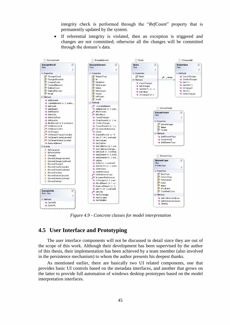
45
integrity check is performed through the “RefCount” property that is
permanently updated by the system.
If referential integrity is violated, then an exception is triggered and
changes are not committed; otherwise all the changes will be committed
through the domain’s data.
Figure 4.9 - Concrete classes for model interpretation
4.5 User Interface and Prototyping
The user interface components will not be discussed in detail since they are out of
the scope of this work. Although their development has been supervised by the author
of this thesis, their implementation has been achieved by a team member (also involved
in the persistence mechanism) to whom the author presents his deepest thanks.
As mentioned earlier, there are basically two UI related components, one that
provides basic UI controls based on the metadata interfaces, and another that grows on
the latter to provide full automation of windows desktop prototypes based on the model
interpretation interfaces.

46
The textual descriptions used in the UI are obtained through the “Label” (and
“PluralLabel”) properties provided on these interfaces.
FieldTypes are used as a mean to associate a basic UI gadget to a data type.
Basically there is a mapping mechanism between FieldTypes and UI gadgets for the
visualization and edition of field instances of that data type.
Some of the existing controls are the following (a short image layout of each
control is also provided after each description):
Field Editors
Used for editing field values. They are composed of a label and a FieldType
based control. This includes a Combo Box based control for enumerations
and for choosing single element references.
Multi Field Editors
Used for editing several field values in a single panel.
List Editors
Used for editing lists of domain elements. There will be buttons to access
every child (composite) and referenced collection fields on a selected
element. These are also available in the form of grids that allow for in-cell
edition of field values (each cell is a FieldType based control).
Collection Selectors
Used for adding, removing, and ordering elements in a collection field. The
ReferencePicker mentioned earlier (section 4.2) is used to populate the

47
“Available” elements list.
DomainElement editors with Tabbed Panels
Used for editing the data of a domain element.
The first tab is a general purpose multi field editor for basic fields and there
is an additional tab for each collection field (composite or referenced).
All these controls are resizable and have properties for defining the geometrical
adaptation to their containers. For each of them there’s a possibility of choosing the
actual fields to be used in visualization or for editing. Composed fields are allowed, for
instance, we could say we want the “Department.Boss.Name” field presented in an
Employees list. All field properties of the IField interface are used to present data
accordingly either while editing a single element or an element list.
The difference between composite and reference collection fields is that the first
allows the creation and removal of elements on the collection (see List Editors) and the
latter only allows for adding and removing existing elements from the collection (see
Collection Selectors).
These controls are also available within full working prototype oriented forms. One
of the basic problems on using these forms is that domain changes (in the model
interpretation layer) are single level. This means that there is no way for a “OK/Cancel”
form to call another “Ok/Cancel” based form, since the DomainWorld will only support
cancelling on the first form (otherwise, cancellation on the second form would also
cancel operations on the first form). This has led to the cautious use of edition modes in
those forms particularly with the choice of “Ok/Cancel” and “Close” based forms. The
latter provide operations that are directly committed when “Cancel” is not allowed. The
final prototype editing architecture is presented in Figure 4.10.

48
Figure 4.10 - Prototype editing architecture

49
5 FV-RAD in Action
5.1 Use Cases
FV-RAD, on its current state, may be partially or fully applied, depending on usage
goals. Three typical use cases have been identified:
Generic database applications These applications typically persist their data in a relational database.
Referential integrity is directly supported on the database. Here the
metadata interfaces and their base implementation components may be used
together with the metadata based user interface component. Reporting,
filtering, data import/export, and general user interface development will
benefit from a higher level of abstraction to allow for faster implementation
and run-time configuration.
OPT is using these components for the development of the next version of
the GIST system.
Document persisted applications
These are the applications that benefit the most from this framework. Full
model interpretation may be used to manage the entire domain’s data. Full
user interface automation is used initially to provide working prototypes
that progressively get refined with manual or metadata based user interface
controls for a better user experience and for overcoming the framework’s
limitations.
OPT is using these components for the development of a flat-file light
version of GIST, called GIST Light, and a pre-release more limited version
called “Bus Planner” (see section 5.3).
Prototyping
Prototyping, whether for design validation purposes or as a mean to rapidly
provide initial working versions of an application to be tested near the
stakeholders, fits neatly with the framework’s goals. Full use of the
framework is applied for this purpose.
The lack of a modelling file format (models still have to be defined in code)
is currently the biggest limitation for this intent and is the next priority in

50
the framework’s development (by reusing its own data format). After this is
done, sharing a prototype will be as easy as putting a Model file and its
instance (a World file) in an email (an additional library with binary domain
extensions may also be sent) and sending it to the stakeholder. The
stakeholder only has to own a copy of the prototype execution environment.
He can make run-time changes to the model and returns its suggestions also
in the form of a running prototype.
As the framework grows to support other types of application structure and
persistence mechanisms, as well as new user interface paradigms, the spectrum of
application may broaden to provide a general purpose model oriented run-time
environment for the development of adaptive applications.
5.2 Demonstration
In this section, a brief demonstration of building a running prototype is provided
based on a specific model definition (Company model). All the code for this
demonstration is provided in Appendix C. The steps for building the prototype are the
following:
Model definition
Model implementation
Extending the model
GUI invocation (prototype execution)
Testing (persistence in XML - “.FVX”)
5.2.1 Model Definition
The Company model is presented in Figure 2.1. A Company may have several
departments and employees. Each Department has several Employees and an Employee
may only work in a single Department. An Employee may be assigned for managing
one or more Departments’ activities. Each Employee may have several Degrees of some
type. The types allowed are “basic”, “high school”, “graduation”, “bachelor”, “post-
graduation”, “masters” and “Phd”. Degrees are contained in the structure of an
Employee (composite).

51
Figure 5.1 -The "Company" model
Composite associations are important indications in the model as they provide the
means for managing the life-cycle of entities (removing an Employee implies removing
its Degrees and a Degree is created directly in the Employee that contains it).
The definition of this model may then be presented as a tabular description of all
the entity types and their fields, like the one in Table 5.1. This data is the basis for the
implementation of this model in FV-RAD.
As we can see there is a clear distinction between basic fields and the fields
responsible for describing the associations. The latter have additional columns for
describing the association roles they are involved in.
The Name field in the Employee should be the result of the concatenation of the
firstName and lastName fields. As so it must be declared as a stateless field (IsStatefull
= false).

52
Table 5.1 - "Company" model definition

53
5.2.2 Model Implementation
Because a textual DSL has not still been devised for the definition of the models,
the data definition presented previously in tabular format is not directly perceived by the
framework. As so, it must be programmed in code with the help of the Model
Interpretation component. Figure 5.2 presents the definition of the Employee type.
There are additional elements for giving textual designations on entities and fields.
These will be used in the UI automation process. The “IsHomeType” property for
indicating a root type is described in section 4.4.4 (in IElementyType). Root types will
be accessed from the initial window of the prototype.
Fields only have to define the boolean classifiers that differ from the defaults. We
can see that the Name field is classified as not persistent (“p-“) neither statefull (“s-“)
nor writeable (“w-“) and that it is a key field (“k+”). The “c+” classification of the
degrees field collection indicates that this is a composite reference containing all the
child elements created within.
// Company Model Definition
// Element Types
...
ElementType employeeType
= new ElementType("employee", "Funcionário", "Funcionários");
employeeType.IsHomeType = true;
model.AddElementType(employeeType);
...
// Employee
// Fields
elemType = employeeType;
elemType.AddField(new Field("firstName", FT.String(20), "Primeiro Nome"));
elemType.AddField(new Field("lastName", FT.String(20), "Ultimo Nome"));
elemType.AddField(new Field("birthDate", FT.Date(), "", DateTime.Now,
"Data Nascimento"));
elemType.AddField(new Field("Name", FT.String(), "p- s- w- k+", "Nome"));
elemType.AddField(new Field("degrees", FT.Collection(degreeType, "c+"),
"Habilitações"));
...
Figure 5.2 - Defining the "Employee"entity type
Enumerated field types like the one for enumerating the different types of degrees
(don’t confuse with the Degree element type), may be defined as follows:

54
// Degree Type enumeration
enumType = new FTEnum("degreeType");
enumType.AddItem("none", 0, "Nenhuma");
enumType.AddItem("basic", 1, "Básico");
enumType.AddItem("high school", 2, "Secundário");
enumType.AddItem("graduation", 3, "Licenciatura");
enumType.AddItem("post-graduation", 4, "Pós-graduação");
enumType.AddItem("masters", 5, "Mestrado");
enumType.AddItem("Phd", 6, "Doutoramento");
FT.AddEnum(enumType);
Figure 5.3 - Defining the "degreeType" enumeration
Subsequent references to this enumeration type may be accessed through the
“enumType” variable or through “FT.Enum(“degreeType”)”. Remaining model
definition is presented in Appendix C.
5.2.3 Extending the Model
Model code extensions will be explained through the implementation of the
Employee’s Name field. FV-RAD does not have a modelling language for describing
behaviour like for instance saying that “Name = firstName + „ „ + lastName”. As so this
will have to be implemented in code. The implementation is provided by overriding the
method used for accessing field values (“Get<T>(…)” method), in “employee” entities.
To do that, one must ensure that there is a specific class for the entities where this
method will be overridden. Since a DomainWorld only instantiates DomainElement
generic objects one must force it to instantiate “Employee” classes whenever they are
created, and that is done by overriding the “NewElement(…)” method of a sub-class of
DomainWorld called “CompanyWorld” that manages all Company entity instances (see
Figure 5.4).
public class CompanyWorld : DomainWorld
{
public CompanyWorld()
: base(Company.Model)
{
}
public override IDomainElement NewElement(
IElementType elementType, string key)
{
switch (elementType.Name)
{
case "employee":
return new Employee(key);
default:
return base.NewElement(elementType, key);
}
}
}
Figure 5.4 - Extending a "DomainWorld"

55
We may now proceed to define a “Employee” class for overriding the “Get”
method that accesses field values and imposing the calculation of the Name field (see
Figure 5.5).
public class Employee : DomainElement
{
public static int firstNameIndex;
public static int lastNameIndex;
public static int NameIndex;
static Employee()
{
firstNameIndex = Company.EmployeeType.GetIndex("firstName");
lastNameIndex = Company.EmployeeType.GetIndex("lastName");
NameIndex = Company.EmployeeType.GetIndex("Name");
}
public Employee(string key)
: base(Company.EmployeeType, key)
{
}
public override T Get<T>(int fieldIndex)
{
object result;
if (fieldIndex == NameIndex)
{
// "Name" calculation
result = FirstName + " " + LastName;
}
else
{
return base.Get<T>(fieldIndex);
}
return (T)result;
}
public string Name
{
get { return this.Get<string>(NameIndex); }
}
public string FirstName
{
get { return this.Get<string>(firstNameIndex); }
set { this.Set<string>(firstNameIndex, value); }
}
public string LastName
{
get { return this.Get<string>(lastNameIndex); }
set { this.Set<string>(lastNameIndex, value); }
}
}
Figure 5.5 - The "Employee" extended entity type
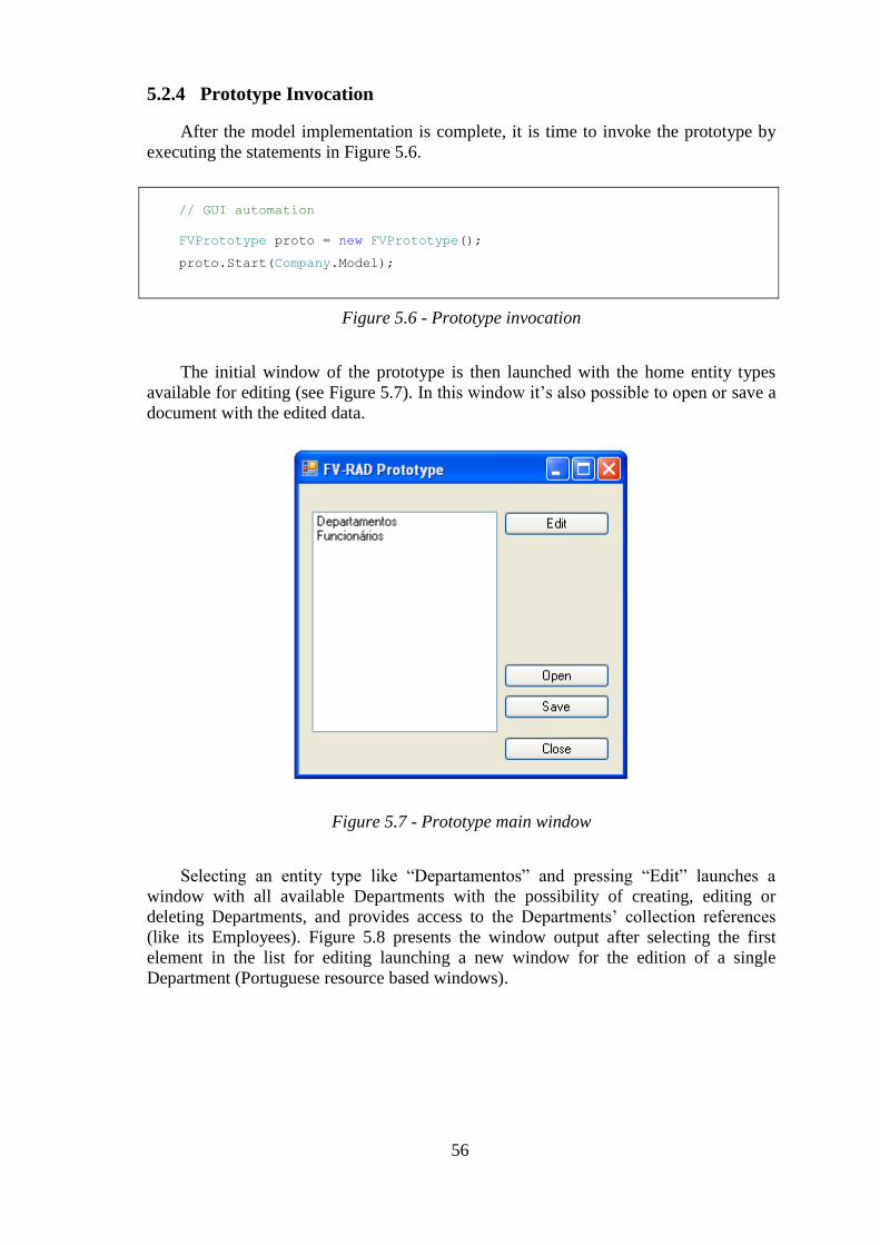
56
5.2.4 Prototype Invocation
After the model implementation is complete, it is time to invoke the prototype by
executing the statements in Figure 5.6.
// GUI automation
FVPrototype proto = new FVPrototype();
proto.Start(Company.Model);
Figure 5.6 - Prototype invocation
The initial window of the prototype is then launched with the home entity types
available for editing (see Figure 5.7). In this window it’s also possible to open or save a
document with the edited data.
Figure 5.7 - Prototype main window
Selecting an entity type like “Departamentos” and pressing “Edit” launches a
window with all available Departments with the possibility of creating, editing or
deleting Departments, and provides access to the Departments’ collection references
(like its Employees). Figure 5.8 presents the window output after selecting the first
element in the list for editing launching a new window for the edition of a single
Department (Portuguese resource based windows).

57
Figure 5.8 - Running the "Company" prototype
The prototype is able to generate a log of all object oriented transactions with the
changes that occurred in the entities. For instance, when opening a new “.FVX”
document for this domain, a load operation is executed for the creation of all data from
the document within the DomainWorld in a single transaction. The output for this log is
presented in Figure 5.9. As you can see there is also an indication of reference count
changes on every entity.
World changes BEGIN.
['department:1' initialized]
Created 'department:1'
['department:2' initialized]
Created 'department:2'
['department:3' initialized]
Created 'department:3'
['employee:1' initialized]
Created 'employee:1'
['degree:1' initialized]
Created 'degree:1'
[Add 'degree:1' to 'employee:1'.degrees]
['degree:1' ref 1]
['degree:2' initialized]
Created 'degree:2'
[Add 'degree:2' to 'employee:1'.degrees]
['degree:2' ref 1]
['employee:2' initialized]
Created 'employee:2'
['degree:3' initialized]

58
Created 'degree:3'
[Add 'degree:3' to 'employee:2'.degrees]
['degree:3' ref 1]
['degree:4' initialized]
Created 'degree:4'
[Add 'degree:4' to 'employee:2'.degrees]
['degree:4' ref 1]
['employee:3' initialized]
Created 'employee:3'
['employee:4' initialized]
Created 'employee:4'
['employee:5' initialized]
Created 'employee:5'
['employee:6' initialized]
Created 'employee:6'
['employee:7' initialized]
Created 'employee:7'
[Set 'department:1'.manager to 'employee:7']
['employee:7' ref 1]
[Add 'employee:6' to 'department:1'.employees]
['employee:6' ref 1]
[Add 'employee:7' to 'department:1'.employees]
['employee:7' ref 2]
World changes CONFIRM.
Figure 5.9 - FV-RAD's Domain Log
5.2.5 Testing and Persistence
Testing the prototype is an important task. Code tests may be implemented just as
any other application by calling the model interpretation engine and experimenting with
the entities. Other tests may be UI centred and the persistence mechanism plays an
important role by providing an easy way to transport domain data across the
stakeholders. The “.fvx” XML based files generated by FV-RAD are also very readable
by direct edition in a text or XML editor allowing for direct manipulation of the data.
Figure 5.10 presents the document contents for the domain data that generated the log in
Figure 5.9. XML schema generation isn’t yet supported by FV-RAD.
<?xml version="1.0" encoding="utf-8"?>
<company version="1.0.0">
<department key="department:1" name="Marketing" manager="employee:7">
<notes>Relações públicas e gestão de campanhas.</notes>
<employees>
<ref key="employee:6" />
<ref key="employee:7" />
</employees>
</department>
<department key="department:2" name="Operações">
<notes>Planeamento da actividade produtiva</notes>
<employees />
</department>
<department key="department:3" name="Comercial">
<notes>Planeamento da actividade de vendas</notes>
<employees />
</department>
<employee key="employee:1" firstName="Luís" lastName="Ferreira" birthDate="1968-10-

59
16">
<degrees>
<degree key="degree:1" designation="Engenharia de Sistemas e Informática"
degreeType="graduation" />
<degree key="degree:2" designation="Informática" degreeType="post-
graduation" />
</degrees>
</employee>
<employee key="employee:2" firstName="Fernando" lastName="Vieira" birthDate="1971-
03-28">
<degrees>
<degree key="degree:3" designation="Matemática e Ciências da Computação"
degreeType="graduation" />
<degree key="degree:4" designation="Informática" degreeType="post-
graduation" />
</degrees>
</employee>
<employee key="employee:3" firstName="Sara" lastName="Silva" birthDate="0001-01-
01">
<degrees />
</employee>
<employee key="employee:4" firstName="João" lastName="Castro" birthDate="0001-01-
01">
<degrees />
</employee>
<employee key="employee:5" firstName="Sara" lastName="Meireles" birthDate="0001-01-
01">
<degrees />
</employee>
<employee key="employee:6" firstName="Lurdes" lastName="Ribeiro" birthDate="0001-
01-01">
<degrees />
</employee>
<employee key="employee:7" firstName="Manuela Ribeiro" birthDate="0001-01-01">
<degrees />
</employee>
</company>
Figure 5.10 - FV-RAD's documents (".FVX")
5.3 Applying FV-RAD to “Bus Planner”
FV-RAD has been successfully applied to the “Bus Planner” project at OPT (see
Figure 5.11). The discussion on this implementation will be centred on the model
transformations that took part in the model definition process. The resulting model
definition data is presented in tabular form in Appendix D.
This is an application that allows a Bus Company to manage its resources, namely
in terms of the trips offered to the public and the lines (routes) they are assigned to, the
bus duties needed to fill those trips, and the driver duties needed for driving those buses.
The full model is presented in Figure 5.12. It has been sectioned in two parts, one for
modelling the transport network and another for trip and resource scheduling purposes,
so the classes that join those two segments appear twice.

60
Figure 5.11 - BusPlanner application
The model presented has some features that cannot be directly implemented with
FV-RAD’s framework, which are the following (base knowledge of UML class
diagrams is assumed):
Association Classes
These are classes that characterize associations. In fact these classes are
associations with modelled structure and behaviour. They are not directly
supported by FV-RAD. Examples are the LinePath and PathNode
association classes.
Shared Aggregation
This is the general case of aggregation where several parent container
objects may share the same contained child object. Only composite
aggregation is supported in FV-RAD. Examples are the BusDuty and
DriverDuty being able to share WorkBlock instances.
Binary Associations
These are associations that are to be implemented both ways. FV-RAD is
still not able to automatically synchronize references in both roles of the
association. An example is the N-N Trip-WorkBlock association that needs
Trip.WorkBlocks and WorkBlock.Trips role fields synchronized at all times.

61
Figure 5.12 - BusPlanner model diagram

62
The association classes are dealt by a simple transformation process by converting
the N-N directed association class C in Figure 5.13.
A B**
C
Figure 5.13 - FV-RAD and Association Classes
Class C is then converted into a class whose elements are contained (composite) in
the source class A and where those elements point to single B instances, although
several Cs may point to the same B (see Figure 5.14).
A C B* 1*
Figure 5.14 – Converting a N-N directed Association Class
Shared aggregation may be transformed into composite aggregation by a
transformation process that tries to find a compatible parent class for WorkBlock going
up the composition hierarchy. In this case the most suitable class is Schedule. The next
step is putting WorkBlocks contained in Schedules, instead of DriverDuty and BusDuty
where the aggregation construct is transformed into regular references.
Implemented binary associations must have the synchronization process managed
with code extensions, so that when an element is added or removed in one side the
opposite reference must be added or removed in the other side of the association.
The transformation process has to be processed case by case taking FV-RAD’s
limitations into consideration. The resulting transformed diagram for this model is
presented in Figure 5.15 and its conversion to tabular data is presented in Appendix D.
BusPlanner has benefited from FV-RAD with increased development speed and
early deployment of initial prototypes that were progressively refined till final release.
UI data manipulation was not the only benefit provided by FV-RAD. Automatic
persistence of data and the ability to use data change events for controlling the update of
the graphical representation presented in Figure 5.11 were also important gains that
allowed for the rapid development of this application.
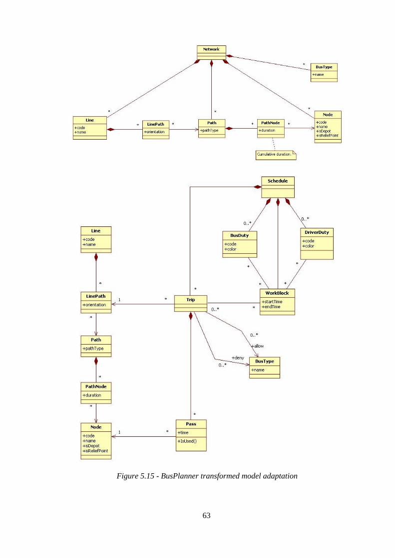
63
Figure 5.15 - BusPlanner transformed model adaptation

64
6 Conclusions
Models are becoming the most important artefacts in software development. Their
integration in the development process is a fundamental aspect of current software
methodologies. It is the next step in raising the abstraction level on development tools
and languages.
There are currently several important trends in model oriented development from
which the following two have been highlighted in this thesis:
One that uses design-time generative software methodologies to build the
application or to generate reusable assets for building a family of domain
related applications. This is based in highly abstract Domain Specific
Languages that provide an ideal mean for domain experts to express a
problem and for developers to build the infrastructure that generates the
solution.
Other that uses adaptive methodologies for interpreting metadata based
models at run-time and providing the means for rapid changes to a model
aware application through its model definition.
FV-RAD fits the latter with a general purpose approach for interpreting an
adaptation of UML class based models. It has a broad scope by covering important
aspects as domain logic, persistence and user interface. It also flavours several use
cases, from a platform that allows for an increased level of UI automation and utilities
based on metadata, to a complex full automation prototype provider for running models
with optional code extension mechanisms. These mechanisms are used for overcoming
its limitations and for refining an application till final release is reached.

65
6.1 Goal Analysis
Initial goals were ambitious and there were high expectations which have been
more than partially fulfilled. Several accomplishments have been realized in this
project:
Layered architecture A general layered architecture has been devised for metadata based
applications, for the run-time interpretation of UML class based models,
and for running fully automated prototypes. The architecture has been set
upon abstract interfaces for making the API as general as possible and a
base implementation has also been provided.
Metadata based applications
By being able to support intermediate metadata based UI automation and
metadata based utilities it has proven to be a valuable platform for general
purpose applications. These may be client server applications based on a
relational database that don’t need full model running capabilities, like the
GIST system whose next version is being developed using this approach.
Document based applications
Flat file persisted applications are a natural candidate for using this
framework. They may start with a rough full prototype draft
implementation, with automated user interface and persistence, and they get
progressively refined with model changes and code extensions for
achieving final results. The “BusPlanner” project at OPT has clearly
benefited from this rapid approach.
Running prototypes
Running model based prototypes is a good way of testing design options
and concepts. FV-RAD provides the means for running these models
without the need of a development environment or application setup, which
is ideal for sharing these prototypes with the stakeholders. It also provides
automatic persistence with a portable XML based format (“.FVX”) that
may be easily edited or exchanged over email.
In House
Although its commercial exploration is an option, the fact that this is a inner
development gives OPT a firsthand knowledge of its benefits and
limitations and the ability to make it fit for its own needs.
Model learning platform
One important aspect of using this framework which has been noted at OPT
it is its ability to be used as an academic tool for teaching about conceptual
models in application design. By running a model based prototype the
student is rapidly able to analyse the impact of his modelling decisions on
the final application.
Also there have been some problems and limitations, some of which have already
been stated. These have somehow affected the ease of use and also have prevented a
broader spectrum of appliance for this framework:
Modelling format and tools
The lack of a modelling format for persisting models is one of the main
drawbacks of this version. This is particularly harmful for prototyping

66
purposes, as it imposes the need to code the model definition using the
framework which for a first-time user means learning the framework’s API.
Also a tool for building these models or for importing a base model
definition in a standard format (ex: XMI – XML Metadata Interchange) and
adapting them for its use would also be of great value. Currently OPT
defines models with StarUML (open source), then produces a transformed
version with the same tool after which there is an Excel template where this
definition is put in tabular format before being implemented in FV-RAD.
Complexity
Learning to use the framework’s API, depending on the use scope, may
take a while. The learning curve is particularly higher with respect to code
extensions. This may be a problem, especially with a first time use team for
a short time constrained project. This is however compensated with rapid
development gains after the framework has been tackled.
Performance
Performance is not a concern when using the basic layer for metadata based
applications. However it is an important factor when using the full model
interpretation engine to manage data. For instance, field values are stored as
objects, their state is replicated for managing changes (ex: cancelling
changes), and entity lifecycle is managed manually besides the regular
garbage collection process of the implementation platform. For
performance constrained applications this might be an important limitation.
Database persistence
There is currently no support for database persistence, particularly multi-
user databases. These applications may only benefit from the basic
metadata layer. In fact, although the model interpretation API tried not to
compromise the future addition of this feature, it has never been intended
for first releases. Model interpretation is currently directed toward in-
memory processing of domain data that is persisted in flat-files.
Changes are already being made to overcome some o these and other limitations,
these include a partial rewrite of the user interface layers for automation and
prototyping (for WPF – Windows Presentation Foundation).
It is also important to distinguish this framework from current object-relational
technology (there’s been some confusion). Object relational tools (ex: Hibernate,
OpenAccess, etc.) provide direct mapping of class instances (objects) to relational
databases. Besides the obvious fact that FV-RAD does not currently support database
persistence, the substantial fact still remains that ORM frameworks work at the
implementation level by facilitating changes to data in objects, which get synchronized
with the database. These objects follow an already determined class structure. FV-RAD
works at a higher level of abstraction (the model), where the implementation platform is
a secondary concern and higher semantic constructs like composition and field
classification may be applied. Another example of this is the proliferation of label
descriptions for supporting things like UI automation and reporting tools. Also, FV-
RAD is about run-time adaptation of applications to new requirements which in ORM
tools may only be directed towards the mapping mechanism (a new field can’t be added
by changing the mapping file unless it has also been added to the class in code and re-
compiled).

67
6.2 Future Work
FV-RAD is still an evolving framework with several limitations and a growing
prospect. It is already being used in some projects at OPT and there are several
improvements being prepared for the next releases:
Explicit metamodel
Explicitly defining FV-RAD’s metamodel using its own modelling schema
is an almost finished task. It will allow for the execution of a prototype
describing a model and for reusing the same persistence format for models
and domain data.
Visual DSL
A visual DSL for describing FV-RAD’s models would be an extremely
helpful tool that would ease the learning curve for the execution of
prototypes.
Schema generation
Currently, data is saved to a XML file (“.FVX”) whose structure depends
on the model. It would be nice to also generate a XML schema for the
automatic validation of data for that model.
Multi-level changes
Only single level transactions are currently supported. Multi-level
transactions would be of great interest particularly for UI automation, as
several levels of “OK/Cancel” data editors would be easily supported.
Undo / Redo
Document based applications typically have an Undo/Redo feature. In FV-
RAD it should be based on the ability to undo or redo full transactions.
Binary associations
Binary associations have to be managed through code extensions. A feature
that would allow for automatic synchronization of references in both roles
of these associations would be very welcome.
Shared aggregation support
Only composite aggregation is currently supported. Shared aggregation
native support would bypass the need for additional model transformations.
Unique fields and indexes
These would provide for additional data validation and improve system
performance in more complex operations.
Improved UI support
The UI layers are already being improved. There is still no support for
inheritance in the UI prototypes and WPF support is being implemented.
Web based support would also be of great value.
Model conversion
As prototypes evolve, all the domain data from previous model versions
may be lost, unless the framework is prepared for learning the differences
between consecutive versions for automatic data conversion.
Behavioural constructs
As typical of AOM systems it would be of great value the support for
behavioural constructs at the model level that would overcome the need for
code extensions in some validation and operational procedures.

68
An interesting vision for the future is one where the developer only has to send two
data files (model and domain data) to enable the stakeholder to test and validate or
suggest changes to the prototype. Another way to do this would be loading the model in
a web site that would be ready to provide an automatic web based UI for model
execution and sharing between the stakeholders.
In the long run more ambitious trends could be followed:
Multi-user database support
The run-time automation of multi-user model based prototypes is a complex
task. For that reason it has been excluded from the first release. Changes to
the modelling structure would most surely have to occur to make this
possible. The potential gains however are huge. Even more when those
prototypes could be refined to become production releases. Combined with
a web user interface, full web application support could be a reality not far
from reach.
Cloud computing
Running models in the cloud is a very ambitious plan that is far from being
accomplished. Cloud computing is a new technology waiting to be explored
and still limited in terms of data support. If this support could be provided
through a higher level of abstraction through general purpose model based
data support, then building a web service could be as easy as defining a
model, implementing some extensions, and executing it in the cloud. These
domain oriented data services could be provided together with an additional
UI automated or partially automated layer for full application support.
These are just some speculating ideas. The baseline is that by raising the level of
abstraction through the use of model oriented technologies the possibilities are
immense. The model-implementation gap gets shorter to a point where the
implementation is merged with the model. This merging process may be directed by the
implementation or by the model itself (model embedded or implementation embedded).
Application development gets faster as things like data management, persistence and
user interface get fully or partially automated, with the possibility of being further
refined by using lower level implementation technology. Quality is improved as cross
cutting concerns get implanted in this infrastructure, and a higher level of response to
requirement changes is provided by the early deployment of working prototypes that
may be validated and even changed by the stakeholders.

69
References
[Arsanjani'01] Arsanjani, A., Grammar-Oriented Object Design: Creating Adaptive
Collaborations and Dynamic Configurations with Self-Describing Components
and Services, in Proceedings of the 39th International Conference and
Exhibition on Technology of Object-Oriented Languages and Systems
(TOOLS39). 2001, IEEE Computer Society.
[Arsanjani'01] Arsanjani, A., Rule Pattern Language 2001: A Pattern Language for
Adaptive Manners and Scalable Business Rule Design and Construction, in
Proceedings of the 39th International Conference and Exhibition on Technology
of Object-Oriented Languages and Systems (TOOLS39). 2001, IEEE Computer
Society.
[BeckAndres'05] Beck, K. and Andres, C., Extreme programming explained :
embrace change. 2nd ed. 2005, Boston, MA: Addison-Wesley. xxii, 189 p.
[BRJ'05] Booch, G., Rumbaugh, J., and Jacobson, I., The unified modeling
language user guide. 2nd ed. 2005, Upper Saddle River, NJ: Addison-Wesley.
xviii, 475 p.
[ClementsNorthrop'02] Clements, P. and Northrop, L., Software product lines :
practices and patterns. The SEI series in software engineering. 2002, Boston:
Addison-Wesley. xxx, 563 p.
[CDLM'05] Crous, T., Danzfuss, T., Liebenberg, A., and Moolman, A., Adaptive
object modelling using the .NET framework, in.NET Technologies 3rd
International Conference. 2005.
[CzarneckiEisenecker'00] Czarnecki, K. and Eisenecker, U., Generative
programming : methods, tools, and applications. 2000, Boston: Addison
Wesley. xxvi, 832 p.
[Czarnecki'04] Czarnecki, K., Overview of generative software development, in
In Proceedings of Unconventional Programming Paradigms (UPP) 2004, 15-17
September, Mont Saint-Michel, France, Revised Papers. 2004, Springer-Verlag.
p. 313-328.
[DKV'00] Deursen, A. v., Klint, P., and Visser, J., Domain-specific languages: an
annotated bibliography. SIGPLAN Not., 2000. 35(6): p. 26-36.
[Evans'04] Evans, E., Domain-driven design : tackling complexity in the heart of
software. 2004, Boston: Addison-Wesley. xxx, 529 p.
[FayadSchmidt'97] Fayad, M. and Schmidt, D. C., Object-oriented application
frameworks. Commun. ACM, 1997. 40(10): p. 32-38.

[Fowler'03] Fowler, M., Patterns of enterprise application architecture. The
Addison-Wesley signature series. 2003, Boston: Addison-Wesley. xxiv, 533 p.
[Frankel'03] Frankel, D., Model driven architecture : applying MDA to enterprise
computing. 2003, New York: Wiley. xxii, 328 p.
[FuentesValecillo'04] Fuentes, L. and Valecillo, A., An introduction to UML profiles.
The European journal for the Informatics Professional, 2004(April): p. 6-13.
[GoF'95] Gamma, E., Helm, R., Johnson, R., and Vlissides, J., Design patterns:
elements of reusable object-oriented software. Addison-Wesley Professional
Computing Series. 1995, Reading, MA [etc.]: Addison Wesley. XV, 395.
[GreenfieldShort'03] Greenfield, J. and Short, K., Software factories: assembling
applications with patterns, models, frameworks and tools, in Companion of the
18th annual ACM SIGPLAN conference on Object-oriented programming,
systems, languages, and applications. 2003, ACM: Anaheim, CA, USA.
[GreenfieldShort'04] Greenfield, J. and Short, K., Software factories : assembling
applications with patterns, models, frameworks, and tools. 2004, Indianapolis,
IN: Wiley Pub. xxix, 666 p.
[JBR'99] Jacobson, I., Booch, G., and Rumbaugh, J., The unified software
development process. The Addison-Wesley object technology series. 1999,
Reading, Mass: Addison-Wesley. xxix, 463 p.
[JohnsonWoolf'97] Johnson, R. and Woolf, B., Type object, in Pattern languages of
program design 3. 1997, Addison-Wesley Longman Publishing Co., Inc. p. 47-
65.
[Johnson'92] Johnson, R. E., Documenting frameworks using patterns, in OOPSLA
'92: conference proceedings on Object-oriented programming systems,
languages, and applications. 1992, ACM: Vancouver, British Columbia,
Canada. p. 63-76.
[JosephYoder'98] Joseph, B. F. and Yoder, J., Metadata and Active Object-Models,
in Dept. of Computer Science, Washington University Department of Computer
Science. 1998.
[KSSSZ'02] Kollman, R., Selonen, P., Stroulia, E., Systä, T., and Zundorf, A., A study
on the current state of the art in tool-supported UML-based static reverse
engineering, in Ninth Working Conference on Reverse Engineering. 2002. p.
0022.
[Laddad'03] Laddad, R., AspectJ in action : practical aspect-oriented programming.
2003, Greenwich, CT: Manning. xxx, 481 p.
[Lewis'95] Lewis, T. G., Object-oriented application frameworks. 1995, Greenwich:
Manning. viii, 344 p.
[Manolescu'00] Manolescu, D., Micro-Workflow: A Workflow Architecture
Supporting Compositional Object-Oriented Software Development. 2000,
University of Illinois at Urbana-Champaign.
[Martin'91] Martin, J., Rapid application development. 1991: Macmillan Publishing
Co., Inc. 788.
[MellorBalcer'02] Mellor, S. J. and Balcer, M. J., Executable UML : a foundation
for model-driven architecture. 2002, Boston ; San Francisco ; New York:
Addison-Wesley. xxxiv, 368 p.
[Meyer'97] Meyer, B., Object-oriented software construction. 2nd ed. 1997, Upper
Saddle River, N.J.: Prentice Hall PTR. xxvii, 1254 p.

[Neighbors'80] Neighbors, J. M., Software construction using components. 1980,
University of California, Irvine. p. 217.
[OMG'09] OMG, OMG Unified Modeling Language (OMG UML) - Infrastructure
and Superstructure specification. 2009, Version 2.2.
[Parnas'76] Parnas, D., On the design and development of program families. IEEE
Transactions on Software Engineering, 1976(March).
[RichtersGogolla'99] Richters, M. and Gogolla, M., Validating UML models and OCL
constraints. Lecture notes in computer science, 1999. 1939/2000: p. 265-277.
[RFBO'01] Riehle, D., Fraleigh, S., Bucka-Lassen, D., and Omorogbe, N., The
architecture of a UML virtual machine, in Proceedings of the 16th ACM
SIGPLAN conference on Object-oriented programming, systems, languages, and
applications. 2001, ACM: Tampa Bay, FL, USA.
[Royce'87] Royce, W. W., Managing the development of large software systems:
concepts and techniques, in Proceedings of the 9th international conference on
Software Engineering. 1987, IEEE Computer Society Press: Monterey,
California, United States.
[RJB'05] Rumbaugh, J., Jacobson, I., and Booch, G., The unified modeling
language reference manual. 2nd ed. The Addison-Wesley object technology
series. 2005, Boston: Addison-Wesley. xx, 721 p.
[SchwaberBeedle'02] Schwaber, K. and Beedle, M., Agile software development with
Scrum. Series in agile software development. 2002, Upper Saddle River, NJ:
Prentice Hall. xvi, 158 p.
[StahlVölter'06] Stahl, T. and Völter, M., Model-driven software development :
technology, engineering, management. 2006, Chichester, England ; Hoboken,
NJ: John Wiley. xvi, 428 p.
[SGM'03] Szyperski, C., Gruntz, D., and Murer, S., Component software : beyond
object-oriented programming. 2nd ed. Addison-Wesley component software
series. 2003, London ; Boston, MA: Addison-Wesley.
[WebAOM] Adaptive Object Models and Meta Modeling. Available from:
http://www.adaptiveobjectmodel.com
[WebAOSD] Aspect-Oriented Software Association, aosd.net. Available from:
http://aosd.net
[WebVölter] Web and Völter, M., Model-Driven Software Development Tutorial.
[WebCzarneckiHelsen] A Taxonomy and Categorization of Model Transformation
Approaches. Available from: http://www.swen.uwaterloo.ca/~kczarnec/
[YBJ'01] Yoder, J. W., Balaguer, F., and Johnson, R., Architecture and design of
adaptive object-models. SIGPLAN Not., 2001. 36(12): p. 50-60.

72
Appendix A - Metadata Interfaces
This is the code for FV-RAD’s metadata interfaces described in section 4.2.
namespace Opt.FieldValues
{
/// <summary>
/// The set of fields that describe an element's typed interface.
/// </summary>
public interface IEntityType
{
int FieldCount { get; }
IField GetField(string fieldName);
IField GetField(int fieldIndex);
int GetIndex(string fieldName);
IEnumerable<IField> Fields { get; }
IEnumerable<string> GetView(); // Default view
IEnumerable<string> GetView(string viewName);
}
/// <summary>
/// An element's external or internal (statefull) data field.
/// </summary>
public interface IField
{
/// <summary>
/// Field name used to identify it in the element.
/// </summary>
string Name { get; }
/// <summary>
/// Field name used to label user interface elements.
/// </summary>
string Label { get; }
/// <summary>
/// Field data type.
/// </summary>
IFieldType FieldType { get; }
/// <summary>
/// Default value when a new element is created.
/// </summary>
object Default { get; }

73
/// <summary>
/// External read permission.
/// </summary>
bool AllowRead { get; }
/// <summary>
/// External write permission
/// </summary>
bool AllowWrite { get; }
/// <summary>
/// Should this field be saved when persisting data in a file
/// or database.
/// </summary>
bool IsPersistent { get; }
/// <summary>
/// Is this field part of its element internal state.
/// </summary>
bool IsStatefull { get; }
/// <summary>
/// Is "null" an allowed value?
/// </summary>
bool AllowNull { get; }
bool IsKeyField { get; }
//bool IsUnique { get; }
//bool IsUniqueInParent { get; }
//
//int ReverseFieldIndex { get; } // Binary associations.
}
public interface IFieldType
{
string Name { get; }
Type Type { get; }
object Default { get; }
/// <summary>
/// Is this field type a reference to one or several elements.
/// </summary>
bool IsReference { get; }
bool IsEnum { get; }
void Validate(object value); // Throws exception on error.
}
/// <summary>
/// Describes a field type used to reference one or several
/// elements.
/// </summary>
/// <remarks>
/// A typical association between two element types.
/// </remarks>
public interface IReference
{
IEntityType RefType { get; }
bool IsChild { get; } // Aggregation (composition)
//bool IsSharedChild { get; } // False => Composition,
// // True => Shared aggregation.
bool IsElement { get; }
bool IsCollection { get; }
bool IsList { get; }
IReferencePicker Picker { get; } // Fetches elements that may be picked
// to be added.
//// Cardinality
//int MinCount { get; }
//int MaxCount { get; }
}
public interface IEnum
{

74
IEnumerable<IEnumItem> EnumItems { get; }
IEnumItem GetItem(string name);
IEnumItem GetItem(int value);
}
public interface IEnumItem
{
string Name { get; }
int Value { get; }
string Label { get; }
}
/// <summary>
/// This is the interface that every element should implement to get or set its
/// field values.
/// </summary>
public interface IFieldValues
{
T Get<T>(string fieldName);
T Get<T>(int fieldIndex);
void Set<T>(string fieldName, T value);
void Set<T>(int fieldIndex, T value);
}
public interface IFilter
{
bool Verify(IFieldValues element);
}
}

75
Appendix B - Model Interpretation
Interfaces
This is the code for the model interpretation interfaces described in section 4.4.4.
namespace Opt.FieldValues.Changes
{
/// <summary>
/// Generic interface used to control and cancel changes to something.
/// </summary>
public interface IChangeable
{
bool IsChanged();
/// <summary>
/// Verifies and confirms changes.
/// Throws an exception if confirmation is not possible.
/// </summary>
void ConfirmChanges();
void CancelChanges();
/// <summary>
/// Verifies if confirmation is possible.
/// </summary>
/// <returns>
/// Returns true if the changes made may be confirmed without
/// Error.
/// </returns>
bool VerifyChanges();
}
public interface IState: IFieldValues, IChangeable
{
bool IsChanged(string fieldName);
bool IsChanged(int fieldIndex);
T GetOld<T>(string fieldName);
T GetOld<T>(int fieldIndex);
IList GetValues();
IEnumerable<IStateChange> GetChanges();
int CountChanges();
}
/// <summary>
/// A Model defines the type of Elements (ElementType) and rules that associated

76
/// Worlds may have.
/// </summary>
public interface IDomainModel
{
string Name { get; }
string Version { get; }
IElementType GetElementType(string typeName);
IEnumerable<IElementType> ElementTypes { get; }
IDomainWorld CreateWorld();
}
/// <summary>
/// An ElementType is a repository of Fields. Some fields may be inherited
/// by a single base Element Type (multiple inheritance not supported yet.
/// </summary>
public interface IElementType: IEntityType
{
string Name { get; }
string Label { get; }
string PluralLabel { get; }
bool IsPersistent { get; }
int StateFieldCount { get; }
IElementType BaseType { get; }
bool IsHomeType { get; }
bool Inherits(IElementType superType);
IEnumerable<int> GetReferenceIndexes();
IEnumerable<int> GetCollectionIndexes();
}
/// <summary>
/// A World is a repository of Elements that follows a specific Model
/// </summary>
public interface IDomainWorld : IChangeable
{
IDomainModel Model { get; }
IEnumerable<IDomainElement> CreatedElements { get; }
IEnumerable<IDomainElement> DeletedElements { get; }
IEnumerable<IDomainElement> ChangedElements { get; }
IDomainElement GetElement(string key);
string GetNewKey(string typeName);
IEnumerable<IDomainElement> GetElements(string typeName);
IDomainElement CreateElement(IElementType elementType);
IDomainElement CreateElement(string key); // Assumes the Key has type
// information. Use carefully
IDomainElement CreateElement(IElementType elementType, string key); // Calls
// "NewElement"
// "NewElement" Requires "AddElement" after to accept the element.
IDomainElement NewElement(IElementType elementType); // Generates the key.
IDomainElement NewElement(string key); // Assumes the key has type
// information. Use carefully
IDomainElement NewElement(IElementType elementType, string key); //
// IMPORTANT: Override to instantiate to user classes
//// Can't override both, only one may be used to instantiate user classes
//IDomainElement NewElement(IElementType elementType, int id); //
// // IMPORTANT: Override to instantiate to user classes
// Operations (changes to world)
void AddElement(IDomainElement element);
bool RemoveElement(IDomainElement element);
void ChangeElement(IDomainElement element);
// EVENTS
event WorldEventHandler Changed;
event WorldEventHandler BeforeConfirm;
event WorldEventHandler BeforeCancel;
event ElementEventHandler ElementCreateConfirmed;
event ElementEventHandler ElementDeleteConfirmed;

77
event ElementEventHandler ElementChangeConfirmed;
event ElementEventHandler ElementCreateCanceled;
event ElementEventHandler ElementDeleteCanceled;
event ElementEventHandler ElementChangeCanceled;
event ElementEventHandler ElementCreated;
event ElementEventHandler ElementDeleted;
event ElementEventHandler ElementChanged;
}
/// <summary>
/// An Element is a repository of Field Values that comply to a
/// specific Element Type.
/// </summary>
public interface IElement: IFieldValues, IChangeable
{
string GetKey();
IElementType ElementType { get; }
IElement Parent { get; }
bool IsPersistent { get; }
IEnumerable<IStateChange> GetChanges();
IEnumerable<ICollectionChange> GetCollectionChanges();
bool IsChanged(string fieldName);
T GetOld<T>(string fieldName);
IElement GetElement(string fieldName, string key);
IElement GetElement(string fieldName, int listIndex);
IElement GetElement(string fieldName);
void AddElement(string fieldName, IElement element);
void AddElement(string fieldName, IElement element, int listIndex);
void MoveElement(string fieldName, int fromIndex, int toIndex);
bool RemoveElement(string fieldName, IElement element);
void RemoveElement(string fieldName, int listIndex);
void ClearElements(string fieldName);
IEnumerable<IElement> GetElements(string fieldName);
ICollection<IElement> GetCollection(string fieldName);
IEnumerable<ICollectionChange> GetCollectionChanges(string collFieldName);
IList<IElement> GetList(string fieldName);
int GetCount(string fieldName);
int GetCount(string fieldName, string key);
IElement CreateElement(string fieldName);
bool IsChanged(int fieldIndex);
T GetOld<T>(int fieldIndex);
IElement GetElement(int fieldIndex, string key);
IElement GetElement(int fieldIndex, int listIndex);
IElement GetElement(int fieldIndex);
void AddElement(int fieldIndex, IElement element);
void AddElement(int fieldIndex, IElement element, int listIndex);
void MoveElement(int fieldIndex, int fromIndex, int toIndex);
bool RemoveElement(int fieldIndex, IElement element);
void RemoveElement(int fieldIndex, int listIndex);
void ClearElements(int fieldIndex);
IEnumerable<IElement> GetElements(int fieldIndex);
ICollection<IElement> GetCollection(int fieldIndex);
IEnumerable<ICollectionChange> GetCollectionChanges(int collFieldIndex);
IList<IElement> GetList(int fieldIndex);
int GetCount(int fieldIndex);
int GetCount(int fieldIndex, string key);
IElement CreateElement(int fieldIndex);
}
/// <summary>
/// A DomainElement is an Element that belongs to a World (DomainWorld).
/// </summary>
public interface IDomainElement : IElement
{
IDomainWorld World { get; }
bool IsNew { get; }
bool IsDeleted { get; }
bool IsDetached { get; }
bool VerifyCreate();
bool VerifyDelete();

78
bool Delete();
}
}

79
Appendix C - Prototype Demonstration
This is the code for the Company demonstration example shown in section 5.2
(Department-Employee).
using Opt.FieldValues.Base;
using Opt.FieldValues.Changes;
using Opt.FieldValues.Gui;
...
namespace Opt.FieldValues.Demo
{
public static class Company
{
public static IDomainModel Model;
public static IElementType DepartmentType;
public static IElementType EmployeeType;
public static IElementType DegreeType;
static Company()
{
Model = new CompanyModel();
DepartmentType = Model.GetElementType("department");
EmployeeType = Model.GetElementType("employee");
DegreeType = Model.GetElementType("degree");
}
}
public class CompanyModel : DomainModel
{
public CompanyModel()
: base("company")
{
// Company Model Definition
// Element Types
ElementType departmentType
= new ElementType("department", "Departamento", "Departamentos");
departmentType.IsHomeType = true;
this.AddElementType(departmentType);
ElementType employeeType
= new ElementType("employee", "Funcionário", "Funcionários");
employeeType.IsHomeType = true;
this.AddElementType(employeeType);
ElementType degreeType
= new ElementType("degree", "Habilitação", "Habilitações");

80
this.AddElementType(degreeType);
// Fields by Element Type
ElementType elemType;
FTEnum enumType;
// Department
// Fields
elemType = departmentType;
elemType.AddField(new Field("name", FT.String(40), "Nome"));
elemType.AddField(new Field("manager", FT.Element(employeeType), "n+",
"Responsável"));
elemType.AddField(new Field("notes", FT.String(), "Notas"));
elemType.AddField(new Field("employees", FT.Collection(employeeType),
"Funcionários"));
// Employee
// Fields
elemType = employeeType;
elemType.AddField(new Field("firstName", FT.String(20), "Primeiro Nome"));
elemType.AddField(new Field("lastName", FT.String(20), "Ultimo Nome"));
elemType.AddField(new Field("birthDate", FT.Date(), "", DateTime.Now,
"Data Nascimento"));
elemType.AddField(new Field("Name", FT.String(), "p- s- w- k+", "Nome"));
elemType.AddField(new Field("degrees", FT.Collection(degreeType, "c+"),
"Habilitações"));
// Degree
// Degree Type enumeration
enumType = new FTEnum("degreeType");
enumType.AddItem("none", 0, "Nenhuma");
enumType.AddItem("basic", 1, "Básico");
enumType.AddItem("high school", 2, "Secundário");
enumType.AddItem("graduation", 3, "Licenciatura");
enumType.AddItem("post-graduation", 4, "Pós-graduação");
enumType.AddItem("masters", 5, "Mestrado");
enumType.AddItem("Phd", 6, "Doutoramento");
FT.AddEnum(enumType);
// Fields
elemType = degreeType;
elemType.AddField(new Field("designation", FT.String(50), "Designação"));
elemType.AddField(new Field("degreeType", FT.Enum("degreeType"),
"Tipo de Habilitação"));
}
public override IDomainWorld CreateWorld()
{
return new CompanyWorld();
}
}
public class CompanyWorld : DomainWorld
{
public CompanyWorld()
: base(Company.Model)
{
}
public override IDomainElement NewElement(IElementType elementType, string key)
{
switch (elementType.Name)
{
case "employee":
return new Employee(key);
default:
return base.NewElement(elementType, key);
}
}
}
public class Employee : DomainElement

81
{
public static int firstNameIndex;
public static int lastNameIndex;
public static int NameIndex;
static Employee()
{
firstNameIndex = Company.EmployeeType.GetIndex("firstName");
lastNameIndex = Company.EmployeeType.GetIndex("lastName");
NameIndex = Company.EmployeeType.GetIndex("Name");
}
public Employee(string key)
: base(Company.EmployeeType, key)
{
}
public override T Get<T>(int fieldIndex)
{
object result;
if (fieldIndex == NameIndex)
{
// "Name" calculation
result = FirstName + " " + LastName;
}
else
{
return base.Get<T>(fieldIndex);
}
return (T)result;
}
public string Name
{
get { return this.Get<string>(NameIndex); }
}
public string FirstName
{
get { return this.Get<string>(firstNameIndex); }
set { this.Set<string>(firstNameIndex, value); }
}
public string LastName
{
get { return this.Get<string>(lastNameIndex); }
set { this.Set<string>(lastNameIndex, value); }
}
}
...
static void Main()
{
// GUI automation
FVPrototype proto = new FVPrototype();
proto.Start(Company.Model);
}
...
}

82
Appendix D – Bus Planner Model
Definition
Tabular definition of BusPlanner’s model from section 5.3.

83

84